Renishaw plc RMP60 probe for machine tools User Manual RMP60 cover for WEB pmd
Renishaw plc probe for machine tools RMP60 cover for WEB pmd
UserManual.wiki
>
Renishaw plc
>
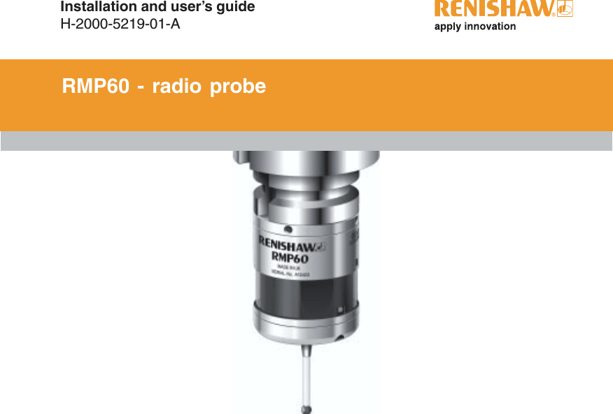
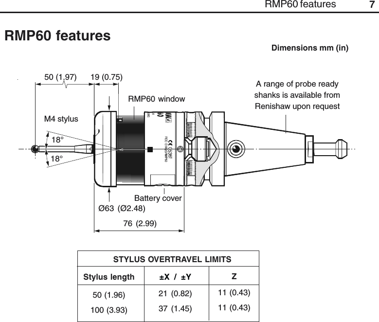
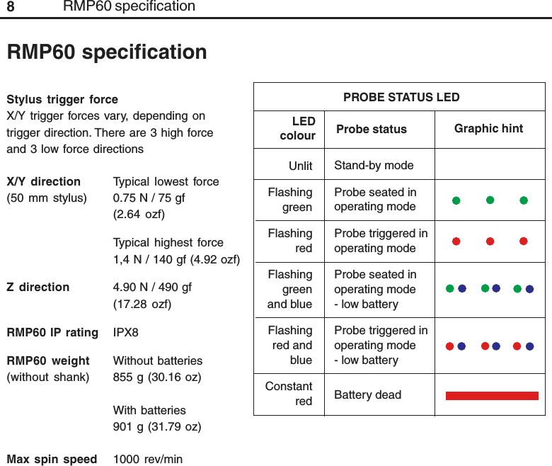
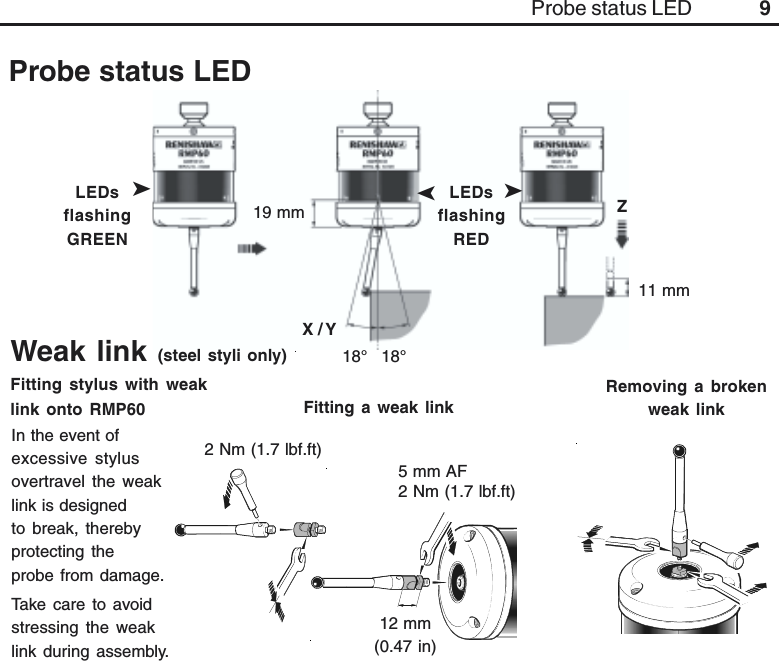
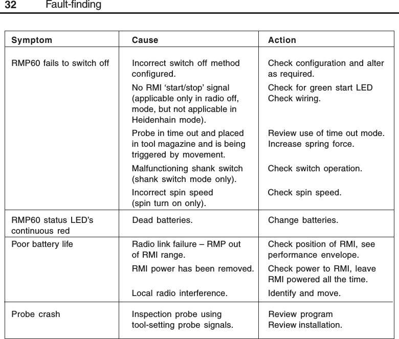
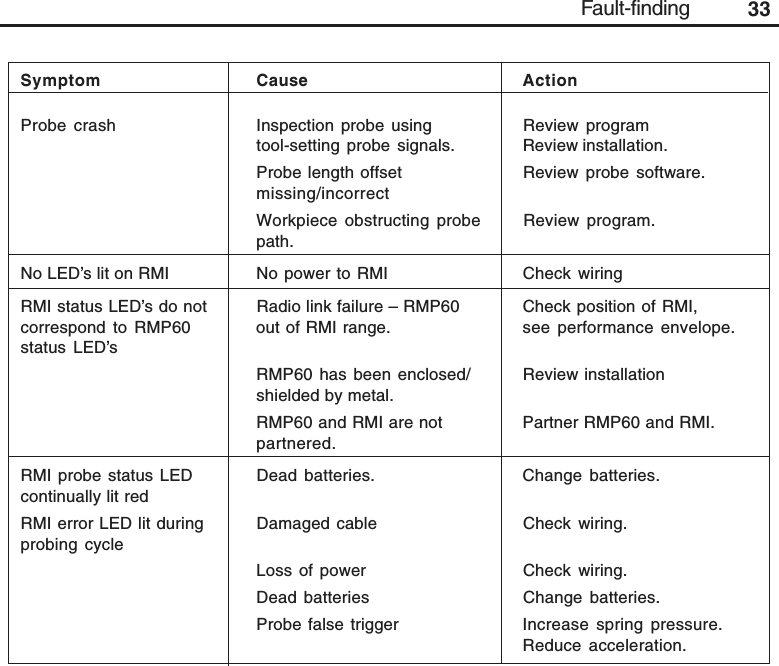
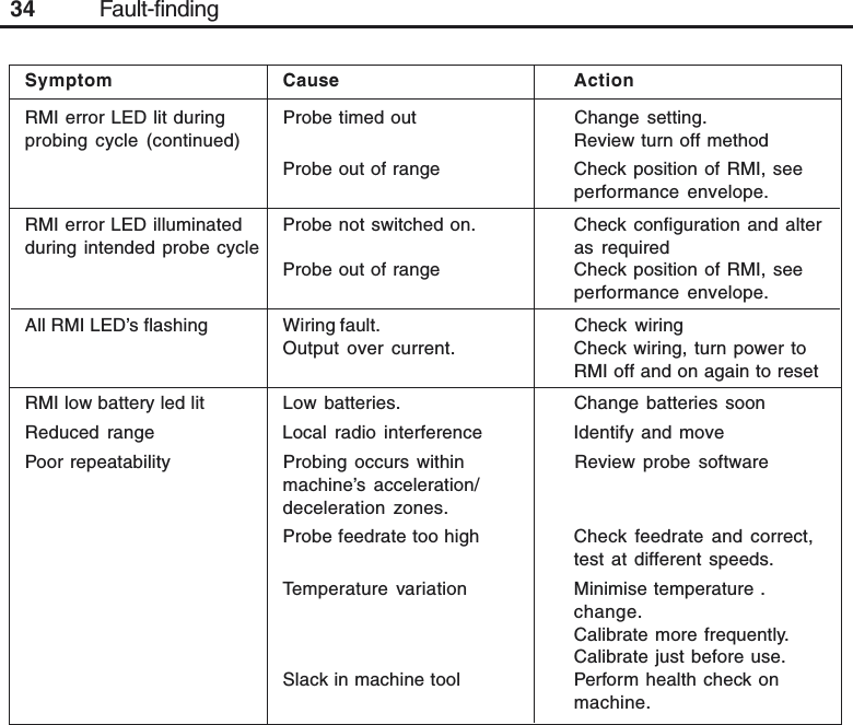
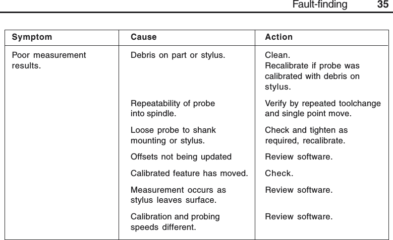
RMP60 User Manual
USER GUIDE
Navigation menu
Upload a User Manual
Namespaces
Wiki Guide
HTML
PDF
Info
Views
User Manual
Discussion / Help
Navigation