Renishaw plc RMP60 probe for machine tools User Manual RMP60 cover for WEB pmd
Renishaw plc probe for machine tools RMP60 cover for WEB pmd
USER GUIDE
Installation and user’s guide
H-2000-5219-01-A
RMP60 - radio probe
© 2003 Renishaw. All rights reserved.
Renishaw® is a registered trademark
of Renishaw plc.
This document may not be copied
or reproduced in whole or in part,
or transferred to any other media or
language, by any means, without the
prior written permission of Renishaw.
The publication of material within this
document does not imply freedom
from the patent rights of Renishaw plc.
Renishaw Part no: H-2000-5219-01-A
Issued: 08.2003
Disclaimer
Considerable effort has been made to ensure
that the contents of this document are free from
inaccuracies and omissions. However, Renishaw
makes no warranties with respect to the
contents of this document and specifically
disclaims any implied warranties. Renishaw
reserves the right to make changes to this
document and to the product described herein
without obligation to notify any person of such
changes.
Trademarks
All brand names and product names used in this
document are trade names, service marks,
trademarks, or registered trademarks of their
respective owners.

1
EC DECLARATION OF CONFORMITY
Renishaw plc declare that the product: -
Name: RMP60
Description: Radio machine probe
has been manufactured in conformity with the following standard: -
BS EN 61326:1998/ Electrical equipment for measurement, control and
laboratory use - EMC requirements.
Immunity to annex A - industrial locations.
Emissions to class A (non-domestic) limits.
and that it complies with the requirements of directive (as amended): -
89/336/EEC - Electromagnetic compatibility
The above information is summarised from the full EC declaration of
conformity. A copy is available from Renishaw on request.

2
Warranty
Equipment requiring attention under warranty
must be returned to your supplier. No claims
will be considered where Renishaw equipment
has been misused, or repairs or adjustments
have been attempted by unauthorised persons.
Changes to equipment
Renishaw reserves the right to change
specifications without notice.
CNC machine
CNC machine tools must always be operated
by competent persons in accordance with
manufacturers instructions.
Installation and user’s guide
Care of the probe
Keep system components clean and treat the
probe as a precision tool.
Patent notice
Features of products shown in this guide,
and of related products, are the subject of the
following patents and/or patent applications:
EP 0652413
US 4599524
US 5,279,042
JP 3,126,797
WO 02/063235
WO 03/021182
Installation and user’s guide

3
Contents
Typical probe system with radio
transmission .................................................... 4
System performance ...................................... 5
Operating envelope ......................................... 6
RMP60 features .............................................. 7
RMP60 specification ....................................... 8
Probe status LED ............................................ 9
Weak link stem ................................................ 9
Modes of operation ....................................... 10
Reviewing current probe settings ................ 12
Configuration using trigger logic ................... 13
System setup/establishing
RMP60/RMI partnership ............................... 15
RMP60 batteries ........................................... 17
Battery life expectancy ................................. 19
RMP60/shank mounting ............................... 21
Stylus on-centre adjustment ......................... 22
Stylus trigger force adjustment ..................... 23
Probe moves ................................................. 24
Software requirements .................................. 26
Typical probe cycles ..................................... 27
Diaphragm replacement ................................ 29
Fault finding .................................................... 31
Appendix 1 RMI ........................................... 36
Parts list ......................................................... 38
Contents
4
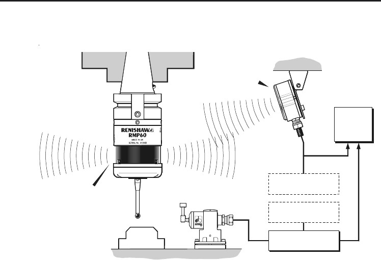
Typical probe system with radio transmission
A workpiece set-up and inspection probe
is in effect another tool in the system.
A probing cycle may be included at any
stage of the machining process.
Typical probe system with radio transmission
CNC machining centre spindle
Typical tool setting probe
C N C
machine
control
Optional - PSU3
power supply unit
RMI
mounting bracket
Interface unit
Cable Optional - PSU3
power supply unit
Workpiece
RMI
Interface
Probe data signals are transmitted via radio link
to the RMI and on to the machine control. The
RMI converts probe signals into an acceptable
form for the machine control.
RMP60
inspection probe
Stylus
Probe status LEDs

5
Operating envelope
Surfaces within the machine may increase the
signal transmission range.
Coolant and swarf residue accumulating on the
RMP60 and RMI may have a detrimental effect
on transmission performance. Wipe clean as
often as is necessary to maintain unrestricted
transmission.
When operating, do not touch with your hand,
either the RMI cover or the probe glass window,
as this will change the performance.
Operation in extremes of temperature will result
in some reduction in range.
RMI position
To assist finding the optimum position of the RMI
during system installation, a signal strength
indication LED is available on the RMI interface.
RMI signal strength is displayed on an RMI
multi-coloured LED.
System performance
System performance
Environment
RMP60
RMI
PSU3
Storage
Normal
operating
Temperature
-10 °C to 70 °C
(14 °F to 158 °F)
5 °C to 50 °C
(41 F° to 122 °F)
Probe repeatability
Maximum 2 Sigma (28) Value
Repeatability of 1,0 µm (40 µ in) is valid for
test velocity of 480 mm/min (1.57 ft/min) at
stylus tip, using stylus 50 mm (1.97 in) long.
6Operating envelope
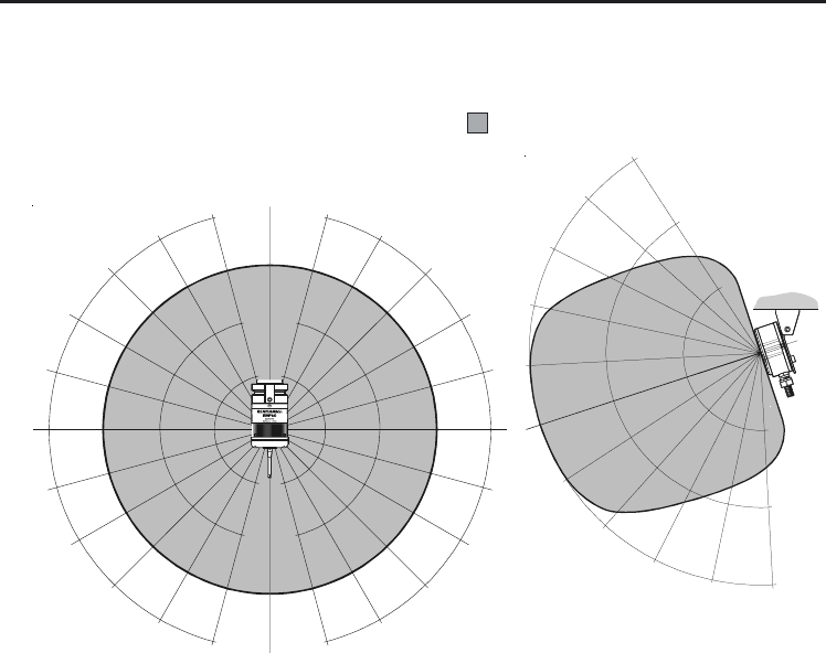
Operating envelope
RMP60 probe + RMI
RMP60 and RMI must be within each others
operating envelope shown.
Range metres (feet)
OPERATING AND SWITCH ON/OFF
90°
75°
60°
45°
30°
15°
0°
15°
30°
45°
60°
75° 90° 75°
60°
45°
30°
15°
0°
15°
45°
60°
75°
75°
60°
45°
30°
30°
45°
60° 75°
10 (33)
15 (49)
5 (16)
5
(16)
10
(33)
15
(49)
10 10
(33) (33)
15 15
(49) (49)
15°
5
(1 6)
7
RMP60 features
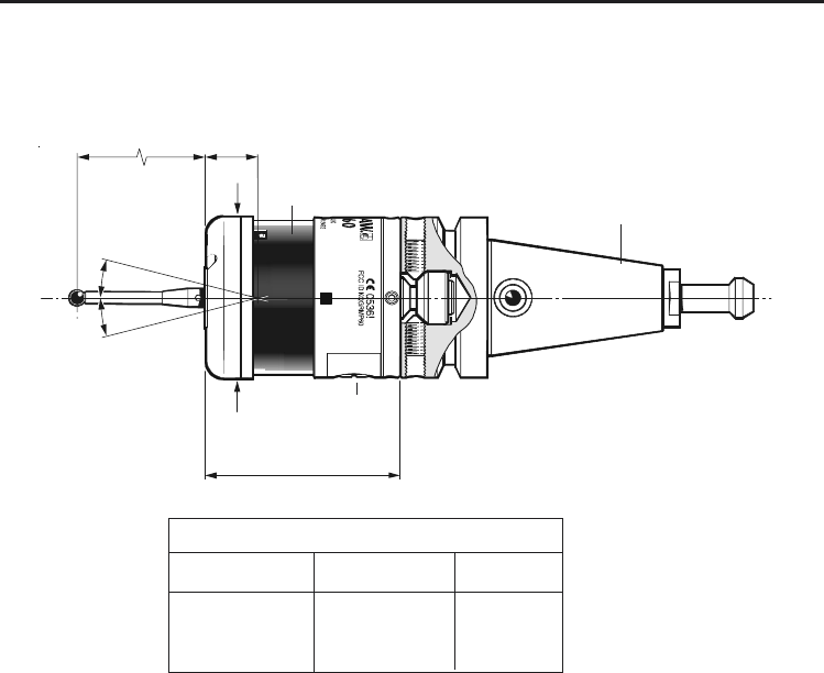
Dimensions mm (in)
RMP60 features
STYLUS OVERTRAVEL LIMITS
Stylus length
50 (1.96)
100 (3.93)
±X / ±Y
21 (0.82)
37 (1.45)
Z
11 (0.43)
11 (0.43)
A range of probe ready
shanks is available from
Renishaw upon request
18°
18°
19 (0.75)
Ø63 (Ø2.48)
50 (1.97)
76 (2.99)
M4 stylus
RMP60 window
Battery cover

8
RMP60 specification
RMP60 specification
Stylus trigger force
X/Y trigger forces vary, depending on
trigger direction. There are 3 high force
and 3 low force directions
X/Y direction Typical lowest force
(50 mm stylus) 0.75 N / 75 gf
(2.64 ozf)
Typical highest force
1,4 N / 140 gf (4.92 ozf)
Z direction 4.90 N / 490 gf
(17.28 ozf)
RMP60 IP rating IPX8
RMP60 weight Without batteries
(without shank) 855 g (30.16 oz)
With batteries
901 g (31.79 oz)
Max spin speed 1000 rev/min
PROBE STATUS LED
Probe status Graphic hint
LED
colour
Unlit
Flashing
green
Flashing
red
Flashing
green
and blue
Flashing
red and
blue
Constant
red
Stand-by mode
Probe seated in
operating mode
Probe triggered in
operating mode
Probe seated in
operating mode
- low battery
Probe triggered in
operating mode
- low battery
Battery dead
9
Probe status LED
Z
X / Y
19 mm
11 mm
18° 18°
LEDs
flashing
GREEN
➤
➤
➤
Probe status LED
Weak link (steel styli only)
Fitting stylus with weak
link onto RMP60
Removing a broken
weak link
5 mm AF
2 Nm (1.7 lbf.ft)
12 mm
(0.47 in)
2 Nm (1.7 lbf.ft)
In the event of
excessive stylus
overtravel the weak
link is designed
to break, thereby
protecting the
probe from damage.
Take care to avoid
stressing the weak
link during assembly.
LEDs
flashing
RED
Fitting a weak link

10
The RMP60 probe can be in one of three modes:
1. Stand-by mode - The RMP60 is waiting for
a switch-on signal .
2. Operating mode - Activated by one of the
switch on methods described on this page.
In this mode and the RMP60 is now ready
for use.
3. Configuration mode - The trigger-logic
configuration method allows a number of
RMP60 set-up options to be configured by
triggering the RMP60, including the switch-off
options described on page 25.
Modes of operation
Modes of operation
RMP60 switch-on
RMP60 power on/off
Switch-on options are configurable
- see page 13.
Three switching methods can be used.
1. Radio start
Radio switch-on is commanded by
M code.
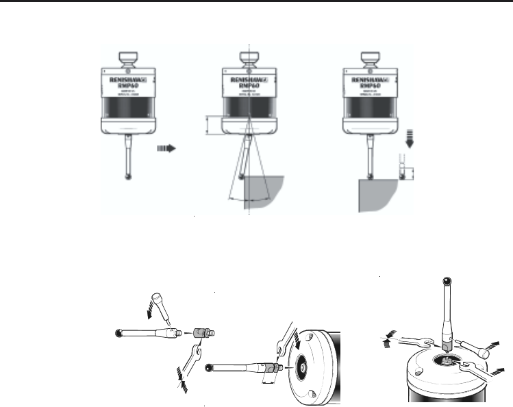
2. Spin start
Spin at 650 rev/min for 1 sec minimum
(maximum 6 sec)
3. Shank switch
Note:
RMP60 will be turned on after 1 sec in all
modes.

11
Modes of operation
RMP60 switch-off
Switch-off options are programmable
Three switching methods can be used.
1. Radio stop
Radio switch off is commanded by a
M code.
(Only applies when radio turn on is
selected).
A timer automatically switches the probe off
after 90 min from last trigger if not turned off
by M-code.
2. Timer off (time out)
(Only applies when radio on/spin on
mode is selected).
The RMP60 will time out (12, 33 or
134 sec) after the last probe trigger or
reseat.
3. Spin stop
(Only applies when spin on mode is
selected).
A timer switch automatically swiches
the probe off after 90 min from last
trigger off, if not spun off.
4. Shank switch
(Only applies when shank on mode is
selected).
Note:
After being turned on, the RMP60 must be
on for a minimum of 1 sec (7 sec for spin
off) before being turned off.
12
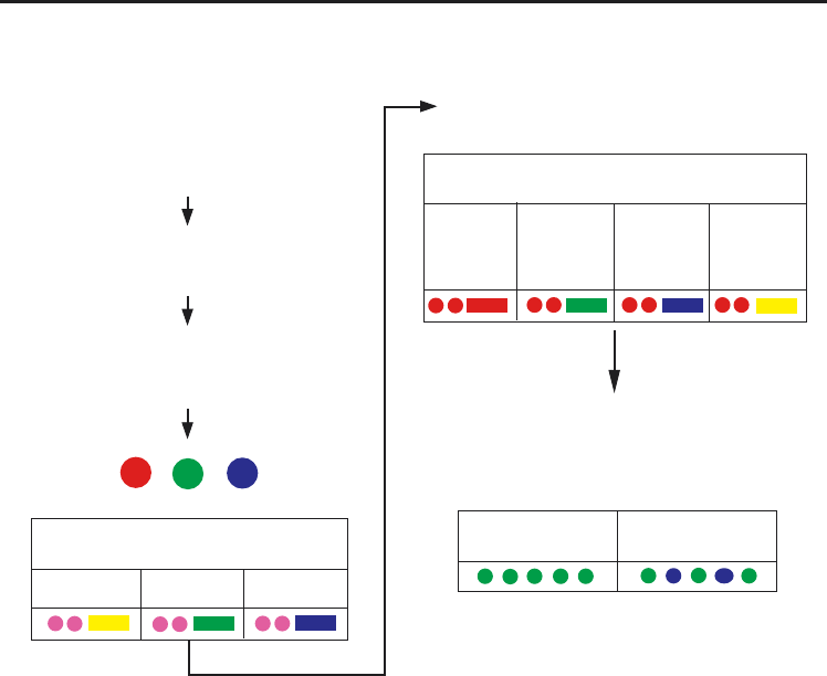
Reviewing current probe settings
START
Batteries removed from probe
Insert batteries: note the LED sequence,
which follows the form below
START UP SEQUENCE
Settings review
LED TEST SEQUENCE
The probe LEDs will always begin with
a colour test
START UP SEQUENCE COMPLETE
The battery status will be displayed and after
10 s the probe will return to stand-by mode
Reviewing current probe settings
SWITCH ON METHOD setting
SWITCH OFF METHOD setting
Note This menu will be omitted if shank
turn on has been selected
RADIO ON SHANK ON SPIN ON
RADIO
or
SPIN
Short
timeout
12 sec
Medium
timeout
33 sec
Long
timeout
134 sec
BATTERY
GOOD
BATTERY
LOW
13
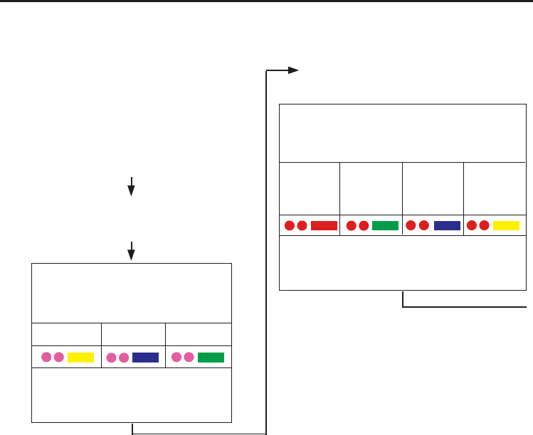
Configuration using trigger logic
START
Remove batteries from probe.
Hold stylus deflected and insert batteries.
Release the stylus only after 15 seconds.
The current probe settings review
sequence, detailed on page 12 will
always be displayed first.
CONFIGURATION MODE
after 15 seconds
continued on next page
Configuration using trigger logic
SWITCH OFF METHOD menu
Deflect the stylus (>0.5 sec) to
cycle between options
Note This menu will be omitted if shank
turn on has been selected
Once the desired switch off option is
selected deflect the stylus for at least
4 sec to move onto next menu
SWITCH ON METHOD menu
Deflect the stylus (>0.5 sec) to
cycle between options
Once the desired switch on option
is selected deflect the stylus for at
least 4 sec to move onto next menu
RADIO ON SPIN ON SHANK ON
RADIO
or
SPIN
Short
timeout
12 sec
Medium
timeout
33 sec
Long
timeout
134 sec
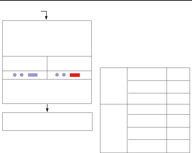
14 Configuration using trigger logic
Switch on
method
Switch off
method
Settings record table
It is recommended that settings are reviewed
after programming. See ‘Reviewing current
probe settings’.
Always keep a record of probe settings
following any programming. These will
be needed should the probe be replaced.
Radio
Shank
Spin
Radio/spin
Short time out
12 sec
Medium time out
33 sec
Long time out
134 sec
from previous page
ACQUISITION MODE menu
Deflect the stylus (>0.5 sec)
to cycle the option on or off
(Note: Once the RMI has been acquired, the
RMP60 will only show acquisition mode off)
ACQUISITION MODE
OFF
ACQUISITION MODE
ON
Once configuration is complete, leave the
RMP60 in triggered for 20 sec to save
configuration and go to stand-by.
Return to
SWITCH ON METHOD menu

15
Setup is done by using the RMP60 trigger logic
and powering on the RMI at a particular time
during the process.
Trigger logic is a method that allows user
configuration of the options available in the
RMP60. Trigger logic uses a sequence of
RMP60 triggering and battery insertion
followed by further RMP60 triggering.
This leads the user through a series of choices
allowing selection of the required options.
Reviewing of choices made can be made by
battery insertion alone. See pages 12 and 13 for
full details of reviewing probe settings and
configuration using trigger logic.
1. Use trigger logic to set RMP60 turn on/ off
modes as desired.
2. Use trigger logic to access RMP60
acquisition mode (light blue flashes, 2 short
1 long).
System setup/establishing RMP60-RMI partnership.
RMP60-RMI partnership
3. Power on the RMI.
4. Wait until RMI signal led flashes green.
5. Trigger the probe (min 0.1 sec max 2 sec)
RMP60 will flash 2 x turquoise short,
followed by 1 red long and repeat until
acquistion occurs.
6. RMI pattern will change to red & yellow
flashing when it acquires the RMP.
7. Allow ~10 seconds for both RMP60 and
RMI to timeout all RMP60 LEDs off and RMI
signal LED off. The system is then ready for
use.
Warning
When holding the RMP60 do NOT wrap
a hand, or anything else, around the
glass window.
!
continued on next page

16
Note.
When the RMP60 and RMI become partners the
RMI records the RMP60 serial number. It is not
possible for an RMI to be partners with more
than one RMP60.
It is possible for an RMP60 to be partners with
more than one RMI, but the system will not
work correctly if more than one partner RMI is
powered on at any one time.
RMP60-RMI partnership

17
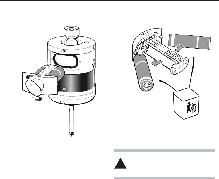
RMP60 batteries
Replacing batteries
Only use specified batteries.
Clean and dry RMP60 with a cloth or paper towel
before removing battery cover. Where the
RMP60 has been exposed to coolant, it is
recommended that the area around the battery
cover is cleaned.
To access the RMP60 batteries, remove the
battery cover by rotating the securing screw
30° anticlockwise and withdraw battery cassette.
Take care to avoid damaging the cover gasket.
When inserting the batteries, ensure they are
loaded as shown (see next page).
If one or more batteries are incorrectly loaded
the probe will not respond.
RMP60 batteries
Do not mix new and used batteries or battery
types, as this will result in reduced life and
damage to the batteries.
Always ensure that the cover gasket and mating
surfaces are clean and free from damage, before
reassembly.
18
DO NOT leave exhausted batteries in probe
DO NOT allow coolant or debris to enter the
battery compartment
DO check for correct battery polarity
RMP60 batteries
Please dispose of exhausted batteries
in accordance with local regulations.
Do not dispose of batteries in fire.
!
Batteries 2 x AA
+
-
+
-
Battery cover

19
Battery life expectancy
Alkaline - Two AA type (see page 20).
Typical battery reserve life
Using the standard alkaline battery at 5 % usage,
typically the probe will continue to operate for
approximately 2 weeks after a low battery
warning is first indicated.
Battery life expectancy
Two
AA type
STAND-BY
LIFE
(days - max)
STAND-BY
LIFE
(days - max)
5% USAGE
72 minutes/day
(days - max)
CONTINUOUS
USE
Alkaline 1,538 115 384 95 144
5% USAGE
72 minutes/day
(days - max)
Replace the batteries as soon as is
practicable.
When inserting new batteries the RMP60 will
flash to show current configuration (page 12).
In order to achieve stated radio stand-by life,
the RMP60 must be in range of powered
partner RMI.
SHANK/SPIN TURN ON RADIO TURN ON
(hours - max)
BATTERY

20 Battery life expectancy
The standard batteries are AA alkaline.
Alternative batteries are lithium thionyl
chloride (3.6 V), NiCad or NiMh.
For applications requiring maximum battery
life, a high capacity lithium thionyl chloride type is
essential.
Sources for lithium thionyl chloride batteries
Please use these specified part numbers only
Supplier Part number
RS 596-602, 201-9438,
Radio Shack 23-037
Manufacturer Part number
Saft LS 14500
Sonnenschein SL 760/S
Tadiran TL-5903/S, TL-2100/S
Xeno XL-060F
Low battery indicators
The low battery warning will be signalled by the
alternate blue flashing of probe status LED
when the end of the usable battery life is
approaching. Simultaneously, the low battery
LED on the RMI will be lit.
Dead battery indicators
When the battery voltage drops below the
threshold where performance can be
guaranteed, the RMP60 probe status LED
will change to constant red.
Battery specification
The RMP60 requires two identical AA size
batteries, individually rated at a voltage of
between 1.2 V and 3.6 V.
21
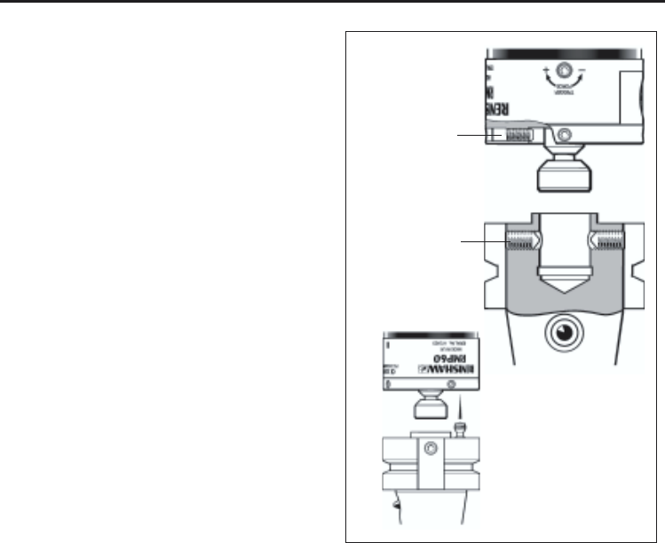
RMP60/shank mounting
RMP60/shank mounting
Note :
1. DURING ADJUSTMENT CARE SHOULD
BE TAKEN NOT TO ROTATE THE RMP60
RELATIVE TO THE SHANK.
2. IF A RMP60/SHANK UNIT IS ACCIDENTALLY
DROPPED, IT SHOULD BE CHECKED FOR
ON-CENTRE POSITION.
3. DO NOT HIT OR TAP THE PROBE TO
ACHIEVE ON-CENTRE ADJUSTMENT.
Stage 1 RMP60/shank mounting
If the RMP60 does not have a shank switch,
please proceed from note 3.
1. Remove plug from rear of RMP60 using pliars.
2. Place bobbin into shank.
3. Fully slacken four screws A.
4. Grease two screws B, and fit into shank.
5. Fit RMP60 onto the shank, and visually
position centrally.
6. Tighten screws B to 6-8 Nm (4.4- 5.9 lb.ft)
(Partially tighten screws B to 2 - 3 Nm
(1.47 - 2.2 lbf.ft), if RMP60 is to be on-centre
adjusted).
7. The RMP60 assembly is ready for use.
B
A
Bobbin
Switch
22
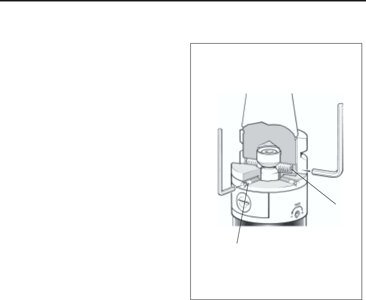
Stylus on-centre adjustment (if required)
Stylus on-centre adjustment
Stage 2 On-centre adjustment
8. Each of the four screws A will move the
probe relative to the shank, in the X or Y
direction as pressure is applied.
Tighten individually, backing off after
each movement.
9. When the stylus tip run-out is less than
20 µm, fully tighten screws B to 6 - 8 Nm
(4.4 - 5.9 lbf.ft).
10. For final centering use screws A to move
the RMP60, progressively slackening on
one side and tightening the opposite screw,
as the final setting is approached, using
two hexagon keys.
Tip run out of 5 µm (0.0002 in) should
be achievable.
11. It is important that all four screws A are
tight or tightened to 1,5 - 3,5 Nm
(1.1 - 2.6 lbf.ft) once the final setting
has been achieved.
2,5 mm AF
4 mm AF
A
B
23
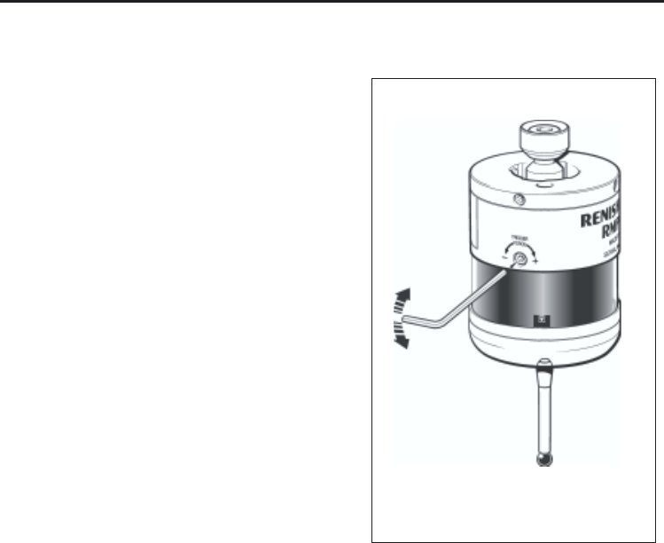
Stylus trigger force adjustment
Stylus trigger force adjustment
Spring force within the probe causes the
stylus to sit in one unique position, and return to
this position following each stylus deflection.
Stylus trigger force is set by Renishaw. The user
should only adjust trigger force in special
circumstances e.g. excessive machine vibration
or insufficient force to support the stylus
weight.
To adjust trigger force, and turn the adjusting
screw anticlockwise to reduce force (more
sensitive) or clockwise to increase force
(less sensitive). A stop prevents damage, which
could be caused by overtightening the adjusting
screw.
2 mm AF
Reduce
force
Increase
force

24
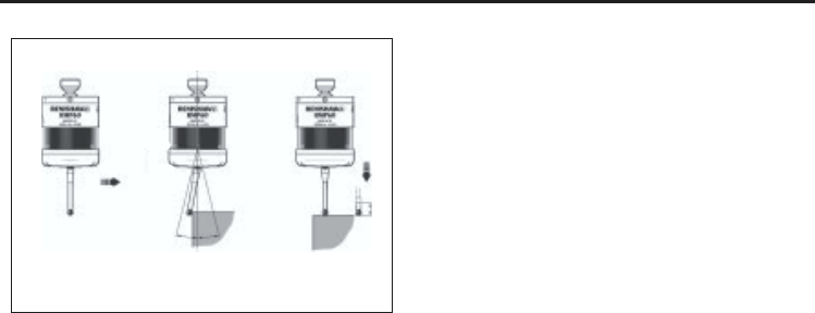
Probe moves
Probe trigger
A probe trigger signal is generated when the
probe’s stylus is driven against a surface.
The machine control records the contact
position and instructs machine motion to stop.
To ensure a trigger signal, drive the probe
against the workpiece to a target beyond the
expected surface, but within the limits of stylus
overtravel. After the probe stylus touches the
surface, reverse clear of the surface.
Single and double touch probing
If the probe operating sequence is based on a
single touch, then the probe is returned to its
start point following a measuring move.
On some types of controller, it is desirable to
use a two touch method, as poor accuracy and
repeatability can result at higher feed rates.
With a double touch sequence the first move finds
the surface quickly. Then the probe is backed off
to a position clear of the surface, before making
the second touch at a slower feed rate, thereby
recording the surface position at a higher
resolution.
Probe measuring speed
The probe system transmission delay time is
small and constant. It does not normally limit the
probing speed, because it is cancelled out during
calibration of the probe on the machine tool.
High probing speeds are desirable, however if
used, a probing velocity must be chosen which
allows the machine to stop within the limits of
stylus overtravel, and measuring capability of
the machine.
Probe moves
25
Calibrating a system
Calibration should be done in the following
circumstances:
1. Before the system is used
2. When a new stylus is used.
3. To allow for machine thermal growth.
4. Poor relocation repeatability of the probe
holder with machine spindle.
It is important that calibration cycles are run at
the measuring cycle feed rate to cancel out
system errors.
Calibration measurements should be made in
every measuring direction to provide complete
calibration data for the measuring cycles.
Probe interface signals
1. Error signal delay
A delay of 28 ms maximum for the RMI, will
elapse between an error occurring and the
output indicating error.
2. Probe signal delay
There is a nominal delay of 10 ms with a
variation of ±10 µs for an interface, from the time
the probe actually operates, to the RMI interface
outputting a probe change of state.
Probing cycles are available from Renishaw
X/Y
Z
X/Y
Probe moves

26
Verify your software
Does your software have suitable calibration
routines which compensate for stylus on-centre
errors? If not, you must set the probe stylus
on-centre mechanically.
Note: Machining centre applications :
When using probe styli which are not on spindle
centre, spindle orientation repeatability is
important to avoid probe measurement errors.
Software requirements
Probing cycles and features are machine
software dependant. Good software will allow the
following functions :
●Simple to use cycles
●Update a tool offset
●If an out of tolerance is found, either
generate an alarm stop, or set a flag for
corrective action
●Update work co-ordinate systems for
positioning
●Print data in the form of an inspection
report to an external PC / printer
●Set tolerances on features
Software requirements
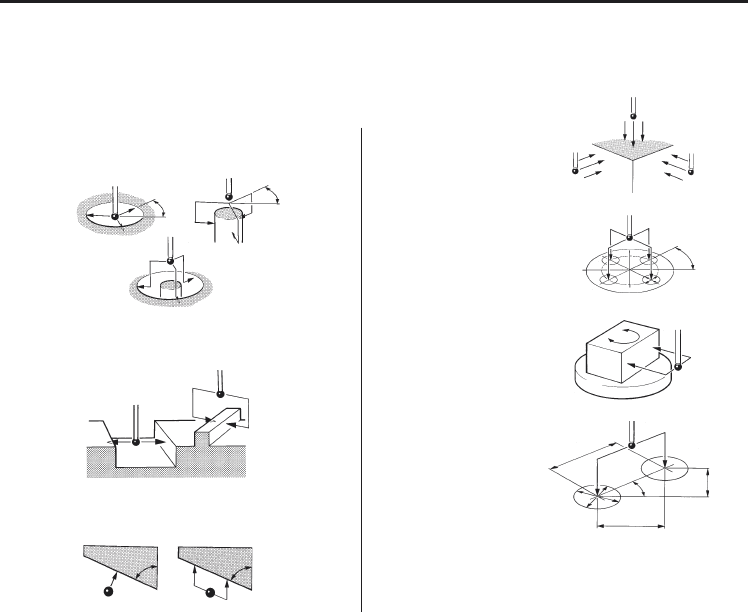
Inspection cycle features
Simple to use canned cycles for standard
features :
Bore/boss. Web/pocket. Single surface.
Simple to use canned cycles for optional
features :
Angle measurement.
Vector 3 point bore/boss.
Vector single surface.
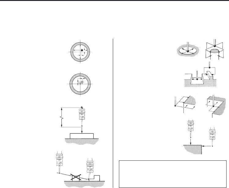
27
Probe length calibration
Typical probe cycles for machining centres
Simple to use canned cycles for basic features
Stylus ball radius
calibration
Inspection probe
collision protection
Internal and external
corner find
Web and pocket
measure
Inspection
Bore and boss measure
XYZ single surface
position
Inspection probe
calibration
Probe XY offset
calibration
Inspection print-out
COMPONENT No. 1
OFFSET NO. NOMINAL TOLERANCE DEVIATION FROM COMMENTS
DIMENSION NOMINAL
99 1.5000 .1000 .0105
97 200.0000 .1000 .2054 OUT OF TOL
Typical probe cycles for machining centres
28
Inspection
Bore and boss (three point)
Stock allowance
Typical probe cycles for machining centres
Simple to use canned cycles for additional features
Angled web and pocket measure 4th axis measure
Bore and boss on PCD
Feature-to-feature
measure
Angled surface measure
Typical probe centres for machining centres
Macro software for use with the RMP60 is
available from Renishaw for the majority of major
controller types, please see Parts list (page 39).

29
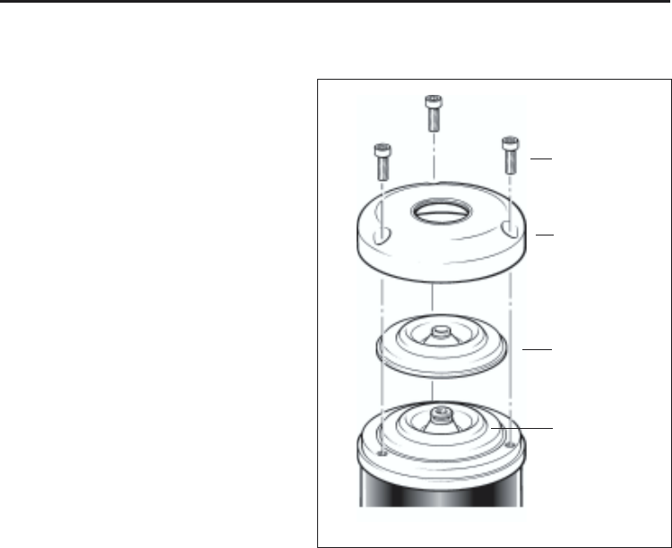
Diaphragm replacement
Diaphragm replacement
RMP60 DIAPHRAGMS
The probe mechanism is protected
from coolant and debris by two diaphragms.
These provide adequate protection under
normal working conditions.
The user should periodically check the
outer diaphragm, for signs of damage. If this
is evident replace the outer diaphragm.
The user must not remove the inner
diaphragm. If damaged, return the probe to
your supplier for repair.
OUTER DIAPHRAGM INSPECTION
1. Remove the stylus.
2. Undo three M3 front cover screws
and remove the front cover
3. Inspect outer diaphragm for damage.
4. To remove outer diaphragm, grip
the edge and pull upwards.
INNER DIAPHRAGM INSPECTION
5. Inspect inner diaphragm for damage.
If damaged return the probe to your
supplier.
DO NOT REMOVE INNER DIAPHRAGM
AS WARRANTY WILL BE VOIDED.
30
M3 screw
2.5 mm AF
1 Nm
(0.74 lbf.ft)
Cover
Outer
diaphragm
OUTER DIAPHRAGM REPLACEMENT
6. Fit new diaphragm over centre.
7. Locate outer edge of diaphragm to rest
on outer edge of inner diaphragm.
8. Refit front cover and M3 screws.
9. Refit stylus and re-calibrate probe.
Diaphragm replacement
Inner
diaphragm

31
Fault finding - If in doubt, consult your probe supplier.
Fault-finding
Symptom Cause Action
RMP60 fails to switch on Dead batteries Change batteries
Batteries incorrectly Check/change batteries
inserted
Probe out of range Check position of RMI, see
(does not apply to spin-on performance envelope.
or shank-on modes)
No RMI ‘start/stop’ signal Check for green start LED
(only applicable in Check wiring
radio-on mode)
No power to RMI Check wiring
(does not apply to spin-on
or shank-on modes)
Incorrect spin speed Check spin speed.
(spin turn-on only)
Malfunctioning shank switch Check switch operation
(shank switch mode only)
Incorrect switch off method Check configuration and alter
configured as required

32 Fault-finding
Symptom Cause Action
RMP60 fails to switch off Incorrect switch off method Check configuration and alter
configured. as required.
No RMI ‘start/stop’ signal Check for green start LED
(applicable only in radio off, Check wiring.
mode, but not applicable in
Heidenhain mode).
Probe in time out and placed Review use of time out mode.
in tool magazine and is being Increase spring force.
triggered by movement.
Malfunctioning shank switch Check switch operation.
(shank switch mode only).
Incorrect spin speed Check spin speed.
(spin turn on only).
RMP60 status LED’s Dead batteries. Change batteries.
continuous red
Poor battery life Radio link failure – RMP out Check position of RMI, see
of RMI range. performance envelope.
RMI power has been removed. Check power to RMI, leave
RMI powered all the time.
Local radio interference. Identify and move.
Probe crash Inspection probe using Review program
tool-setting probe signals. Review installation.

33
Fault-finding
Symptom Cause Action
Probe crash Inspection probe using Review program
tool-setting probe signals. Review installation.
Probe length offset Review probe software.
missing/incorrect
Workpiece obstructing probe Review program.
path.
No LED’s lit on RMI No power to RMI Check wiring
RMI status LED’s do not Radio link failure – RMP60 Check position of RMI,
correspond to RMP60 out of RMI range. see performance envelope.
status LED’s
RMP60 has been enclosed/ Review installation
shielded by metal.
RMP60 and RMI are not Partner RMP60 and RMI.
partnered.
RMI probe status LED Dead batteries. Change batteries.
continually lit red
RMI error LED lit during Damaged cable Check wiring.
probing cycle
Loss of power Check wiring.
Dead batteries Change batteries.
Probe false trigger Increase spring pressure.
Reduce acceleration.

34
Symptom Cause Action
RMI error LED lit during Probe timed out Change setting.
probing cycle (continued) Review turn off method
Probe out of range Check position of RMI, see
performance envelope.
RMI error LED illuminated Probe not switched on. Check configuration and alter
during intended probe cycle as required
Probe out of range Check position of RMI, see
performance envelope.
All RMI LED’s flashing Wiring fault. Check wiring
Output over current. Check wiring, turn power to
RMI off and on again to reset
RMI low battery led lit Low batteries. Change batteries soon
Reduced range Local radio interference Identify and move
Poor repeatability Probing occurs within Review probe software
machine’s acceleration/
deceleration zones.
Probe feedrate too high Check feedrate and correct,
test at different speeds.
Temperature variation Minimise temperature .
change.
Calibrate more frequently.
Calibrate just before use.
Slack in machine tool Perform health check on
machine.
Fault-finding

35Fault-finding
Symptom Cause Action
Poor measurement Debris on part or stylus. Clean.
results. Recalibrate if probe was
calibrated with debris on
stylus.
Repeatability of probe Verify by repeated toolchange
into spindle. and single point move.
Loose probe to shank Check and tighten as
mounting or stylus. required, recalibrate.
Offsets not being updated Review software.
Calibrated feature has moved. Check.
Measurement occurs as Review software.
stylus leaves surface.
Calibration and probing Review software.
speeds different.
36
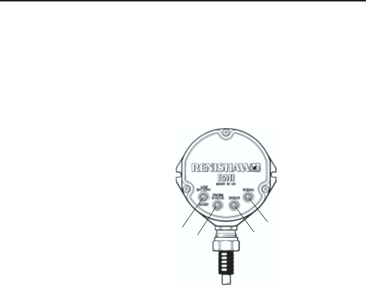
Appendix 1
RMI (RADIO MACHINE INTERFACE)
The RMI is fully described in User's guide H-2000-5220
Appendix 1
A visual indication of system status is provided by light emitting diodes (LED's).
Status is continuously updated and indication is provided for
START, LOW BATTERY, PROBE STATUS, ERROR, SIGNAL STRENGTH
KEEP THE
FRONT COVER
CLEAN
3
14
LED LIGHT SIGNALS
1. Low battery
Red: Battery is low.
Green: M code Start/Stop in
progress.
Yellow: Battery low and M code
Start/stop in progress.
Off: Battery is OK (and no
M code start/stop in
progress).
2. Probe status
Red: Probe triggered or unknown
status.
Green: Probe is seated.
2

37
Appendix 1
3. Error
Red Error, other outputs may
be incorrect.
Off: No Error.
4. Signal
Green Full signal strength.
Yellow Medium signal strength.
Red: Low signal strength, radio
link may fail.
Off No signal detected.
Green/off Flashing: RMI is acquisition
mode, and can acquire a
partner RMP.
Red/yellow Flashing: RMI has (just)
acquired a new partner RMP.
Notes.
1. The probe status LED will always be
illuminated when power is present, there
is no power present LED/light.
2. All the indicators report the status of the
partner RMP. If there is no partner in range,
or the partner is off then the probe status
and error LEDs will be red and the other
LEDs will be off.
3. When the RMI is powered it will enter the
acquire partner mode which will be indicated
by the flashing. After a short time (~12 secs)
it will switch to its normal (passive) mode
listening for its partner.
4. The conditions shown by the low battery,
probe status and error LEDs are the same
as those present on the electrical signal
outputs.

38
RMP60 A-4113-0001 RMP60 probe with batteries, tool kit and User’s guide
(set to radio on/radio off).
RMP60 A-4113-0002 RMP60 probe with batteries, tool kit and User’s guide
(set to radio on/time off).
RMP60 A-4113-0003 RMP60 probe with batteries, tool kit and User’s guide
(set to spin on/spin off).
RMP60 A-4113-0004 RMP60 probe with batteries, tool kit and User’s guide
(set to spin on/time off).
RMP60 A-4113-0005 RMP60 probe with batteries, tool kit and User’s guide
(set to shank switch).
Battery P-BT03-0005 AA batteries - Alkaline - supplied as standard with probe
(two required).
Battery P-BT03-0008 AA batteries - Lithium thionyl chloride (two required).
Stylus A-5000-3709 PS3-1C ceramic stylus 50 mm long with Ø6 mm ball.
Weak link A-2085-0068 Weak link (Part no. M-2085-0069 (x 2) and
5 mm AF spanner.
Parts list - Please quote the Part no. when ordering equipment.
Parts list
Type Part no. Description

39
Parts list
Type Part no. Description
TK A-4038-0208 Probe tool kit comprising: Ø1.98 mm stylus tool,
2.0 mm AF hexagon key, 2,5 mm AF hexagon key (x 2),
4 mm AF hexagon key, shank grub screws (x 2),
weak link and 3 mm AF spanner.
Diaphragm kit M-4038-0138 RMP60 outer diaphragm.
Battery cover A-4038-0218 RMP60 battery casette assembly.
Bobbin A-4038-0056 Bobbin for shank switch.
RMI A-4113-0050 RMI complete with 15 m (49.2 ft) cable.
Mtg brkt A-2033-0830 Mounting bracket with fixing screws, washers and nuts.
PSU3 A-2019-0018 PSU3 power supply unit 85-264 V input.
Styli — For complete listing please see Renishaw Styli guide.
Part no. H-1000-3200.
Software — For complete list of Renishaw software for machine tools
please see Data sheet. Part no. H-2000-2289.
Shanks — For complete listing please see Renishaw Data sheet
H-2000-2011

Renishaw plc
New Mills, Wotton-under-Edge,
Gloucestershire, GL12 8JR
United Kingdom
T+44 (0)1453 524524
F+44 (0)1453 524901
Euk@renishaw.com
www.renishaw.com
For worldwide contact details,
please visit our main website at
www.renishaw.com/contact
*H-2000-5219-01-A*