Renishaw plc RMP60V2 sensor for machine tools User Manual H 2000 5219 05 A RMP60 UG EN cvr
Renishaw plc sensor for machine tools H 2000 5219 05 A RMP60 UG EN cvr
User Manual
Installation and user’s guide
H-2000-5219-05-A
RMP60 - radio machine probe
© 2006 Renishaw. All rights reserved.
This document may not be copied
or reproduced in whole or in part,
or transferred to any other media or
language, by any means, without the
prior written permission of Renishaw.
The publication of material within this
document does not imply freedom
from the patent rights of Renishaw plc.
Renishaw Part no: H-2000-5219-05-A
Issued: 01.06
Disclaimer
Considerable effort has been made to ensure
that the contents of this document are free
from inaccuracies and omissions. However,
Renishaw makes no warranties with respect
to the contents of this document and specifically
disclaims any implied warranties. Renishaw
reserves the right to make changes to this
document and to the product described herein
without obligation to notify any person of such
changes.
Trademarks
RENISHAW® and the probe emblem used in
the RENISHAW logo are registered trademarks
of Renishaw plc in the UK and other countries.
apply innovation is a trademark of Renishaw
plc.
RENISHAW® is a registered trademark of
Renishaw plc in the UK and other countries.
All brand names and product names used in this
document are trade names, service marks,
trademarks, or registered trademarks of their
respective owners.

1
Contents
EC declaration of conformity ........................... 2
FCC declaration ............................................... 3
Safety ............................................................... 3
Installation and User’s guide ........................... 4
Typical probe system with
radio transmission ........................................... 5
System performance ....................................... 6
Operating envelope ......................................... 8
RMP60 dimensions ......................................... 9
Stylus weak link ............................................. 10
Operating mode ............................................. 11
Probe settings................................................ 12
Multiple probe mode ...................................... 14
Reviewing current probe settings .................. 16
Changing probe settings ............................... 18
RMP60-RMI partnership................................ 22
RMP60 batteries ............................................ 24
Battery life expectancy .................................. 26
RMP60 shank mounting ................................ 28
Stylus on-centre adjustment.......................... 29
Stylus trigger force and adjustment .............. 30
Diaphragm replacement ................................ 31
RMP60M system ........................................... 33
RMP60M dimensions .................................... 34
RMP60M screw torque values ...................... 35
Fault finding ................................................... 36
Parts list ......................................................... 41
Probe settings record table .......................... 44
Contents

2
EC DECLARATION OF CONFORMITY
Renishaw plc declares that the product:
Name: RMP60/RMP60M
Description: Radio machine probe
has been manufactured in conformity with the following standard:
BS EN 61326:1998/ Electrical equipment for measurement,
control and laboratory use - EMC requirements.
Immunity to annex A - industrial locations.
Emissions to class A - (non-domestic) limits.
and that it complies with the requirements of directive (as amended):
89/336/EEC Electromagnetic compatibility
The above information is summarised from the full EC declaration
of conformity. A copy is available from Renishaw on request.
Radio approvals

3
FCC DECLARATION (USA)
FCC Section 15.19
This device complies with Part 15 of the FCC rules.
Operation is subject to the following two conditions:
1. This device may not cause harmful interference.
2. This device may accept any interference
received, including interference that may cause
undesired operation.
FCC Section 15.105
This equipment has been tested and found to
comply with the limits for a Class A digital device,
pursuant to Part 15 of the FCC rules. These limits
are designed to provide reasonable protection
against harmful interference when the equipment
is operated in a commercial environment.
This equipment generates, uses , and can radiate
radio frequency energy and, if not installed and
used in accordance with the instruction manual, may
cause harmful interference to radio communications.
Operation of this equipment in a residential area is
likely to cause harmful interference, in which case
you will be required to correct the interference at
your own expense.
FCC Section 15.21
The user is cautioned that any changes or
modifications not expressly approved by Renishaw
plc, or authorised representative could void the
user’s authority to operate the equipment.
SAFETY
Information for the user
Beware of unexpected movement. The user
should remain outside of the full working
envelope of probe head/extension/probe
combinations.
Handle and dispose of batteries in according to
the manufacturers recommendations. Use only
the recommended batteries. Do not allow the
battery terminals to contact other metallic
objects.
In all applications involving the use of machine
tools or CMMs, eye protection is recommended.
Refer to the machine supplier’s operating
instructions.
Information for the machine supplier
It is the machine supplier’s responsibility to
ensure that the user is made aware of any
hazards involved in operation, including those
mentioned in Renishaw product documentation,
and to ensure that adequate guards and safety
interlocks are provided.
Under certain circumstances the probe signal
may falsely indicate a probe seated condition.
Do not rely on probe signals to stop the
machine’s movement.

4
Warranty
Equipment requiring attention under warranty
must be returned to your supplier. No claims
will be considered where Renishaw equipment
has been misused, or repairs or adjustments
have been attempted by unauthorised persons.
Changes to equipment
Renishaw reserve the right to change
specifications without obligation to change
equipment previously sold.
CNC machine
CNC machine tools must always be operated
by competent persons in accordance with
manufacturers instructions.
Installation and user’s guide
Care of the probe
Keep system components clean and treat
the probe as a precision tool.
Patent notice
Features of products shown in this guide,
and of related products, are the subject of the
following patents and/or patent applications:
Installation and user’s guide
EP 0390342
EP 0652413
EP 0695926
EP 1373995
EP 142550
EP 1457786
EP 2,945,709
JP 3,126,797
JP 2004-522,961
JP 2004-279,417
JP 2005-502,035
US 5,040,931
US 5,212,872
US 5,279,042
US 5,669,151
US 6,941,671 B2
US 2003-01799097
WO 2004-057552
WO 2004-090467
5
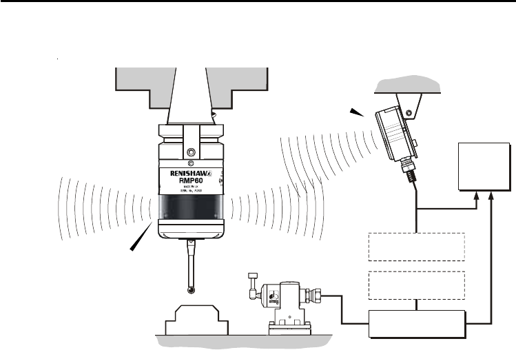
Typical probe system with radio transmission
A workpiece set-up and inspection probe is
in effect another tool in the system. A probing
cycle may be included at any stage of the
machining process.
Typical probe system with radio transmission
CNC machining centre spindle
Typical tool setting probe
C N C
machine
control
Optional
power supply unit
RMI
mounting bracket
Interface unit
Cable Optional
power supply unit
Workpiece
RMI
interface
Probe data is transmitted from the RMP60
(or RMP60M) to the RMI via the radio link.
The RMI converts probe signals into a form
compatible with the machine CNC control.
RMP60
inspection probe
Stylus
Probe status LEDs

6
Operating envelope
Radio transmission does not require line-of sight
and will pass through very small gaps and
machine tool windows. This allows easy
installation, either inside or outside the machine
enclosure.
Coolant and swarf residue accumulating on the
RMP60/M and RMI may have a detrimental
effect on transmission performance. Wipe clean
as often as is necessary to maintain unrestricted
transmission.
When operating, do not touch either the RMI
cover or the probe glass window with your hand,
as this will affect the performance.
Operation in extremes of temperature will result
in some reduction in range.
RMI position
The probe system should be positioned so that
the optimum range can be achieved over the full
travel of the machine axes. Always face the front
System performance
RMP60 and RMP60M have identical user options and radio performance
System performance
Note: RMP60/M in radio-on configuration
The RMP60/M has a built-in hibernate mode
(battery saving mode) that saves battery life
when the RMI is unpowered in radio-on
(radio-off or time-off) configurations.
The RMP60/M goes into hibernate 30 seconds
after the RMI is unpowered (or the RMP60 is
out of range).
When in hibernate, the RMP60/M checks for a
powered RMI every 30 seconds. If found, the
RMP60/M goes from hibernate to standby,
ready for radio-on.
cover of the RMI in the general direction of the
machining area and the tool magazine, ensuring
both are within the operating envelope.
To assist in finding the optimum position of the
RMI, the signal quality is displayed on an RMI
signal LED.

7
Probe repeatability
Maximum 2 Sigma (2σ) value.
Repeatability of 1.0 µm (40 µ in) is valid for a
test velocity of 480 mm/min (1.57 ft/min) at the
stylus tip, using a stylus 50 mm (1.97 in) long.
RMP60 IP rating IPX8
RMP60 weight (without shank)
Without batteries 855 g (30.16 oz)
With batteries 901 g (31.79 oz)
RMP60M weight (without shank)
Without batteries 690 g (24.34 oz)
With batteries 736 g (25.95 oz)
Max spin speed
RMP60 1000 rev/min
RMP60M Dependent on configuration
RMP60
RMP60M
RMI
Storage
Normal
operating
System performance
Environment
Temperature
-10 °C to 70 °C
(14 °F to 158 °F)
5 °C to 50 °C
(41 F° to 122 °F)
8Operating envelope
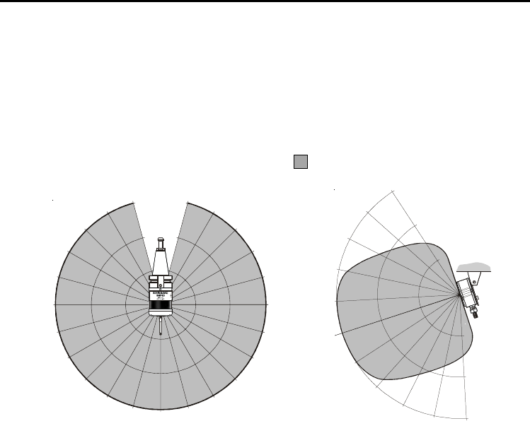
Operating envelope
RMP60 probe + RMI
RMP60 and RMI must be within each other’s
operating envelope. The operating envelope
shows line-of-sight performance, however radio
transmission does not require line-of-sight as
long as any reflected radio path is less than
the 15 m (49.2 ft) system operating range
Range metres (feet)
OPERATING AND SWITCH ON/OFF
Always face the front cover of the RMI in the
general direction of the machining area and
the tool magazine, ensuring both are within
the operating envelope.
75°
60°
45°
30°
15°
0°
15°
30°
45°
60° 75° 90° 75°
60°
45°
30°
15° 0°
15°
45°
60°
75° 75°
60°
45°
30°
30°
45° 60° 75°
10 (33)
15 (49)
5 (16)
5 (16)
10 (33)
15 (49)
15°
0°
15°
30°
5
(16)
10
(33)
15
(49)

9
RMP60 dimensions
RMP60 dimensions dimensions mm (in)
STYLUS OVERTRAVEL LIMITS
Stylus length
50 (1.96)
100 (3.93)
±X / ±Y
21 (0.82)
37 (1.45)
Z
11 (0.43)
11 (0.43)
A range of probe
ready shanks
are available
from Renishaw
18°
18°
19 (0.75)50 (1.97)
M4 stylus
RMP60 window
Battery cassette Shank switch
(optional)
Ø63 (Ø2.48)
76 (2.99)
Bobbin
alignment dot
Status LEDs
10 Stylus with weak link
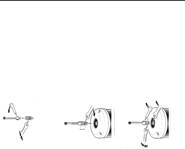
Stylus weak link
Must be used with steel styli.
Removing a broken weak link
For optimum metrology performance, do not use
the weak link with ceramic or carbon fibre styli.
Fitting stylus with weak link onto RMP60
In the event of excessive stylus overtravel,
the weak link is designed to break, thereby
protecting the probe from damage.
Take care to avoid stressing the weak link
during assembly.
Fitting a weak link
12 mm
(0.47 in)
5 mm AF
2 Nm (1.7 lbf.ft)
2 Nm (1.7 lbf.ft)
11
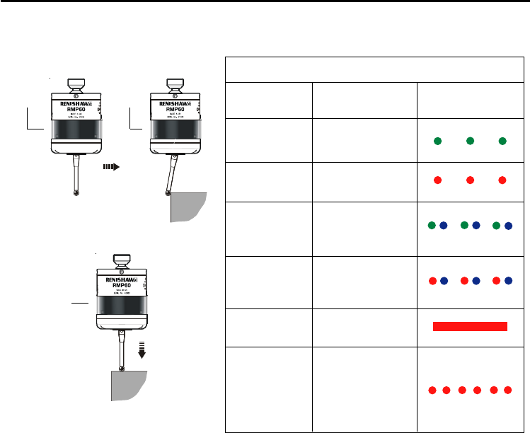
Operating mode
Operating mode
PROBE STATUS LEDs
Probe status Graphic hint
LED colour
Flashing
green
Flashing
red
Flashing
green
and blue
Flashing
red and
blue
Constant
red
Rapid
flashing
red
Probe seated in
operating mode
Probe triggered in
operating mode
Probe seated in
operating mode
- low battery
Probe triggered in
operating mode
- low battery
Battery dead
Extremely dead
alkaline batteries
or unsuitable
lithium thionyl
chloride batteries
Z
X / Y
LEDs
flashing
green
➤➤
LEDs
flashing
red
➤
LEDs
flashing
red

12 Probe settings
The RMP60 probe can be in one of three modes:
Stand-by mode - The RMP60 is waiting for a
switch on signal.
Operating mode - Activated by one of the
switch on methods described on this page.
In this mode the RMP60 is now ready for use.
Configuration mode - The trigger logic
configuration method allows the following
settings to be configured.
Switch-on / switch-off methods
The following switch on / switch off options
can be configured:
1. Radio on / Radio off
2. Radio on / Timer off
3. Spin on / Spin off
4. Spin on / Timer off
5. Shank switch on / Shank switch off
Probe settings
Note:
The RMP60 will be switched on after 1 second
in all modes.
After being switched on, the RMP60 must be
on for 1 second minimum (7 seconds for spin
start) before being switched off.

13
Probe settings
Radio on
Radio switch on when
commanded by an M code.
Spin on
Spin at 650 rev/min for
1 second minimum (6 seconds
maximum).
Shank switch on
Radio off
Radio switch off when commanded by an M code.
A timer automatically switches the probe off after 90 minutes
from the last trigger if not turned off by an M code.
Timer off (time out)
Time out will occur (12, 33 or 134 seconds) after the last probe
trigger or reseat.
Spin off
Spin at 650 rev/min for 1 second minimum (6 seconds
maximum).
A timer automatically switches the probe off after 90 minutes
from the last trigger if not spun.
Timer off (time out)
Time out will occur (12, 33 or 134 seconds) after the last probe
trigger or reseat.
Shank switch off
Switch-on method Switch-off methods available

14
RMP60 can be user configured using trigger
logic to allow multiple RMP60s to be used
with a single RMI.
Multiple probe mode
Multiple probe mode
Note:
Radio turn on cannot be used in multiple probe
mode.
To allow multiple probes/single RMI in close
proximity, 16 choices of ‘mode-on’ colours are
available – each representing a different
machine tool installation. The choices are
shown on the next page and in ‘Changing
probe settings’.
All probes on a single RMI machine should be
set to the same ‘mode-on’ colour choice; any
multiple probes on adjacent machines should
all be set to an alternative ‘mode-on’ colour
choice. Multiple probe mode will not appear in
the configuration of the probe if radio turn on
has been selected.
Note:
Any number of RMP60s set to ‘mode-off’ can
be used alongside RMP60s set to ‘Multiple
probe mode’.
Only one of the multiple probes per machine
will need partnering as, by configuring multiple
probes to a single ‘mode-on’ choice, all probes
have the same identification. The probe to be
partnered, is partnered after selection of
multiple probe on in ‘Changing probe settings’.
There is no limit to the number of probes that
can be used with a single RMI as long as they
all have the same ‘mode-on’ colour choice.
All RMP60s are factory-set to ‘mode off’.
The addition of further probe(s) into a single
probe installation requires all probes to be
re-configured to the same multiple probe
‘mode-on’ choice and the repartnering of
one of the probes to the installed RMI.
The addition of further probes (or replacements)
into a multi probe installation is achieved simply
by reconfiguration to the same ‘mode-on’
colour choice.
15
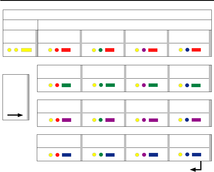
MULTIPLE PROBE MODE
MACHINE 3 MACHINE 4
Multiple mode settings table
MODE OFF
MACHINE 1 MACHINE 2
MODE ON
MACHINE 7 MACHINE 8
MACHINE 5 MACHINE 6
MACHINE 11 MACHINE 12
MACHINE 9 MACHINE 10
Deflect
stylus
< 4 sec
to cycle
to next
setting
MACHINE 15 MACHINE 16
MACHINE 13 MACHINE 14
Return to MODE OFF
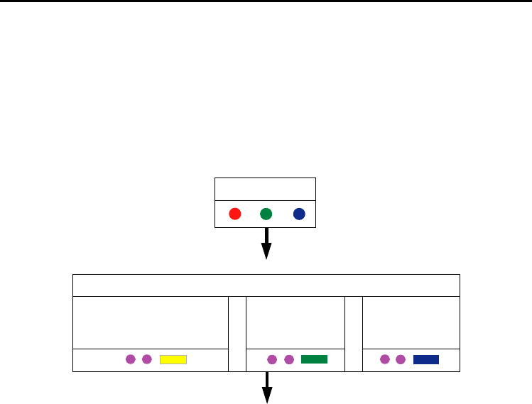
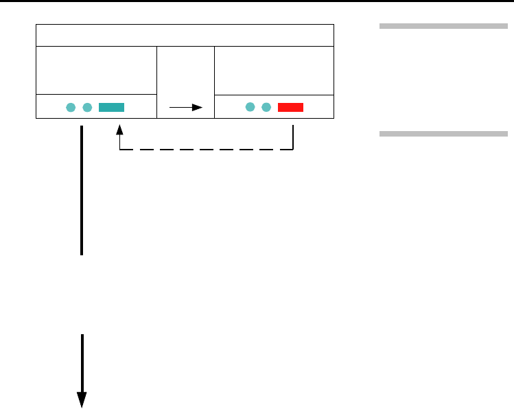
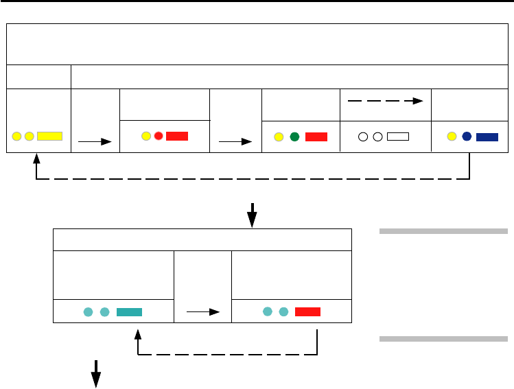
16 Reviewing current probe settings
Reviewing current probe settings
1. Insert batteries, or if already inserted remove
for 5 seconds and replace.
2. DO NOT deflect the stylus when reviewing
settings.
3. The LEDs will show the following sequence.
RADIO ON
(omitted if Multiple Probe
Mode was selected)
SWITCH-ON METHOD
LED CHECK
oror
SPIN ON
SHANK ON
continued on next page
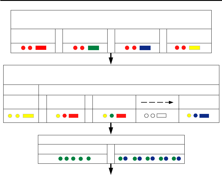
17
SHORT TIME OUT
12 sec
SWITCH-OFF METHOD
(omitted for shank-on)
oror
RADIO OFF
or SPIN OFF
or
MEDIUM TIME OUT
33 sec LONG TIME OUT
134 sec
BATTERY STATUS
BATTERY GOOD
or
BATTERY LOW
PROBE IN STAND-BY MODE (after 5 sec)
MULTIPLE PROBE MODE (omitted for radio-on)
(see ‘Multiple probe mode’ to view all 16 choices)
MACHINE 16
MODE OFF
MACHINE 1 MACHINE 2
MODE ON
Reviewing current probe settings
or or

18
Changing probe settings
1. Insert the batteries, or if already inserted,
remove for 5 seconds and replace.
2. Deflect the stylus and hold deflected until
5 red flashes occur at end of the review
sequence.
Changing probe settings
3. The probe will now be in the configuration
mode and the current switch on method will
flash. The probe settings can be changed as
shown below.
Note:
If battery power is low then each of the
5 red flashes will be followed by a blue flash.
See ‘Probe settings’ for further details.
Note:
Settings are saved as they are changed
Probe settings can be configured using the
trigger logic.
4. To exit the trigger logic at any point, leave
the stylus undeflected for over 20 seconds.
5. Settings record table
For quick reference, Renishaw suggest
that you record your settings in the table
at the back of this guide.
These settings will be needed if the probe
is replaced.

19
Deflect
stylus
< 4 s
Changing probe settings
TO CHANGE SWITCH-OFF METHOD
(omitted if shank turn on was selected)
RADIO
or
SPIN
MEDIUM
TIME OUT
33 s
SHORT
TIME OUT
12 s
Deflect stylus < 4 seconds
Deflect
stylus
< 4 s
Deflect
stylus
< 4 s
LONG
TIME OUT
134 s
Deflect
stylus
< 4 s
TO CHANGE SWITCH-ON METHOD
RADIO ON
(omitted if Multiple Probe
Mode was selected)
SPIN ON
SHANK ON
Deflect stylus < 4 seconds
Deflect stylus > 4 seconds
Deflect
stylus
< 4 s
Deflect stylus > 4 seconds
20 Changing probe settings
Note: After the RMI
has been acquired, the
RMP60 will only show
Acquistion Mode Off.
See RMP60 - RMI
partnership.
Deflect
stylus
< 4 s
ACQUISTION MODE
ACQUISITION MODE
OFF ACQUISITION MODE
ON
Deflect stylus < 4 seconds
Cease triggering here, unless the
multiple probe mode is required
in which case
Deflect stylus > 4 seconds
21
MULTIPLE PROBE MODE
(see “Multiple probe mode” to view all 16 choices)
MODE OFF
MACHINE 1
MODE ON
Deflect stylus > 4 seconds
Deflect
stylus
< 4 s
Return to
TO CHANGE SWITCH-ON METHOD
Deflect
stylus
< 4 s
MACHINE 16MACHINE 2
Deflect stylus < 4 seconds
Note: After the RMI
has been acquired, the
RMP60 will only show
Acquistion Mode Off.
See RMP60 - RMI
partnership.
Deflect
stylus
< 4 s
ACQUISTION MODE
ACQUISITION MODE
OFF ACQUISITION MODE
ON
Deflect stylus < 4 seconds
Changing probe settings
Deflect stylus
> 4 seconds

22
System setup is achieved using trigger logic and
powering on the RMI.
Trigger logic is a method that allows user
configuration of the options available in the
RMP60. Trigger logic uses a sequence of
RMP60 triggering and battery insertion followed
by further RMP60 triggering.
This leads the user through a series of choices,
allowing selection of the required options.
Reviewing of choices can be made by battery
insertion alone. See Reviewing probe settings.
To partner an RMP60 and RMI
Partnering is only required during initial system
set-up. Further partnering is only required if
either the RMP60 or RMI is changed.
Partnering will not be lost by reconfiguration
of probe settings or when changing batteries.
Partnering can take place anywhere within the
operating envelope.
RMP60-RMI partnership
RMP60-RMI partnership
1. Use trigger logic to access the RMP60
configuration mode.
2. Configure the turn on method (if not
configured).
3. Configure the turn off method (if not
configured).
4. Enter the acquisition mode by deflecting
the stylus.
5. Remain in ‘Acquisition Mode Off’ by not
releasing the stylus. This allows time to get
the RMI ready for partnering.
6. Power on the RMI.
7. Watch the RMI signal LED; after a couple
of seconds the LED will repeatedly flash on
and off green. This is the start of a 10
second interval in which the RMI is in
acquisition mode.
continued on next page

23
RMP60-RMI partnership
Note
To check that turn on and off settings have not
accidentally been changed, remove and insert
batteries to review the current probe settings.
Note
When holding the RMP60, do NOT wrap a
hand, or anything else, around the glass
window.
Note
When the RMP60 and RMI become partners
the RMI records the RMP60 identity. It is not
possible for an RMI to be partnered with more
than one RMP60 in ‘Standard Mode’ - see
Multiple Probe Mode.
It is possible for an RMP60 to be partnered
with more than one RMI, but the system will
not function correctly.
8. Release the RMP60 stylus and trigger it a
couple of times. This causes the RMP60 to
go into (and out of) acquisition mode.
9. The RMI signal LED will change to
repeatedly flashing red and yellow (for the
remainder of the 10 second interval),
indicating a successful partnering.
10. Leave the RMP60 for 20 seconds to go
into standby.
11. The system is ready to use.

24
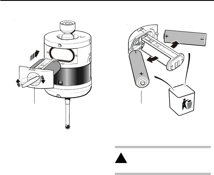
RMP60 batteries
Replacing batteries
Only use specified batteries.
Clean and dry the RMP60 with a cloth or paper
towel before removing the battery cover. Where
the RMP60 has been exposed to coolant, it is
recommended that the area around the battery
cover is cleaned.
To access the RMP60 batteries, remove the
battery cover by rotating the securing screw 30°
anticlockwise and withdraw the battery cassette.
Take care to avoid damaging the cover gasket.
When inserting the batteries, ensure they are
loaded as shown (see next page).
If one or more batteries are incorrectly loaded
the probe will not respond.
RMP60 batteries
Do not mix new and used batteries or battery
types, as this will result in reduced life and
damage to the batteries.
Always ensure that the cover gasket and mating
surfaces are clean and free from damage before
reassembly.
25
DO NOT leave exhausted batteries in probe
DO NOT allow coolant or debris to enter
the battery compartment
DO check for correct battery polarity
RMP60 batteries
Please dispose of exhausted batteries
in accordance with local regulations.
Do not dispose of batteries in fire.
!
Batteries 2 x AA
+
-
+
-
Battery cassette

26
Battery life expectancy
Typical battery life
Using standard alkaline batteries at 5 % usage,
typically the probe will continue to operate for
approximately 1 week after a low battery
warning is first indicated.
Replace the batteries as soon as is practicable.
Battery life expectancy
Two
AA type
STAND-BY
LIFE
(days - typical)
STAND-BY
LIFE
(days - typical)
5% USAGE
72 min/day
(days - typical)
CONTINUOUS
USE
Alkaline 650 100 130 65 140
5% USAGE
72 min/day
(days - typical)
After batteries are inserted into the RMP60,
the LEDs will indicate the current settings.
In order to achieve the stated radio turn-on life
(stand-by or 5% usage), the RMP60 must
be in range of its powered partner RMI.
SHANK/SPIN TURN ON RADIO TURN ON
(hours - typical)
BATTERY
LTC 1,300 200 260 130 280
LTC (Lithium Thionyl Chloride)

27
Battery life expectancy
Sources for lithium thionyl chloride
batteries
Please use these specified part numbers only
Supplier Part number
RS 596-602, 201-9438,
Radio Shack 23-037
Manufacturer Part number
Saft LS 14500
Sonnenschein SL 760/S
Tadiran TL-5903/S, TL-2100/S
Xeno XL-060F
Low battery indicator
The low battery warning will be signalled by
the alternate blue flashing of the probe status
LED when the end of the usable battery life
is approaching. Simultaneously, the low battery
LED on the RMI will be lit.
Dead battery indicator
When the battery voltage drops below the
threshold where performance can no longer
be guaranteed, the RMP60 probe status LED
will change to constant red, followed by flashing
red.
Battery specification
The RMP60 requires two identical AA size
batteries, individually rated at a voltage of
between 1.2 V and 3.6 V.
The standard batteries are AA alkaline.
Alternative batteries are lithium thionyl
chloride (3.6 V), Nickel Cadmium (NiCd) or
Nickel Metal Hydride (NiMh).
Rechargeable batteries: either Nickel Metal
Hydride (NiMh) or Nickel Cadmium (NiCd)
can be used. Expect a battery life of
approximately 50% of alkaline figures.
For applications requiring maximum battery
life, a high capacity lithium thionyl chloride
type is essential.
28 RMP60 shank mounting
B
A
Bobbin
RMP60 shank mounting
Stage 1 RMP60 shank mounting
If the RMP60 is not to be used with a shank
switch, proceed from step 3.
1. Remove the plug from the rear of the
RMP60 using pliers.
2. Place the bobbin into the shank.
3. Fully slacken the four screws A.
4. Grease the two screws B, and fit into the
shank.
5. Fit the RMP60 onto the shank, and visually
position it central relative to the shank.
6. Partially tighten screws B to 2 - 3 Nm
(1.5 - 2.2 lbf.ft).
(If the RMP60 is NOT to be on-centre adjusted,
fully tighten screws B to 6-8 Nm (4.4 - 5.9 lbf ft).
The RMP60 assembly is ready for use.
For on-centre adjustment, complete steps 7-10
(see next page).
Note :
1. During adjustment, care should be taken
NOT to rotate the probe relative to the shank,
as damage to the shank switch bobbin may
occur (if fitted).
2. If a probe on a shank is accidentally
dropped, it should be checked for on-centre
position.
3. Do NOT hit or tap the probe to achieve
on-centre adjustment.
Shank switch
(optional)
Probe to shank alignment dot
(used when bobbin is fitted)
Rear plug
29
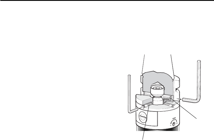
Stylus on-centre adjustment (if required)
Stylus on-centre adjustment
Stage 2 On-centre adjustment
7. Each of the four screws A will move the
probe relative to the shank, in the X or Y
direction, as pressure is applied.
Tighten individually, backing off after each
movement.
8. When the stylus tip run-out is less than
20 µm, fully tighten screws B to 6 - 8 Nm
(4.4 - 5.9 lbf.ft).
9. For final centering, use screws A to move
the RMP60, progressively slackening on one
side and tightening the opposite screw, as
the final setting is approached, using two
hexagon keys.
Tip run out of 5 µm (0.0002 in) should be
achievable.
10. It is important that all four screws A are tight
or tightened to 1.5 - 3.5 Nm (1.1 - 2.6 lbf.ft)
once the final setting has been achieved.
2.5 mm AF
4 mm AF
A
B
SHANK
PROBE
30
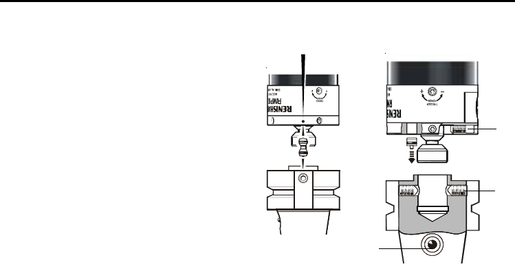
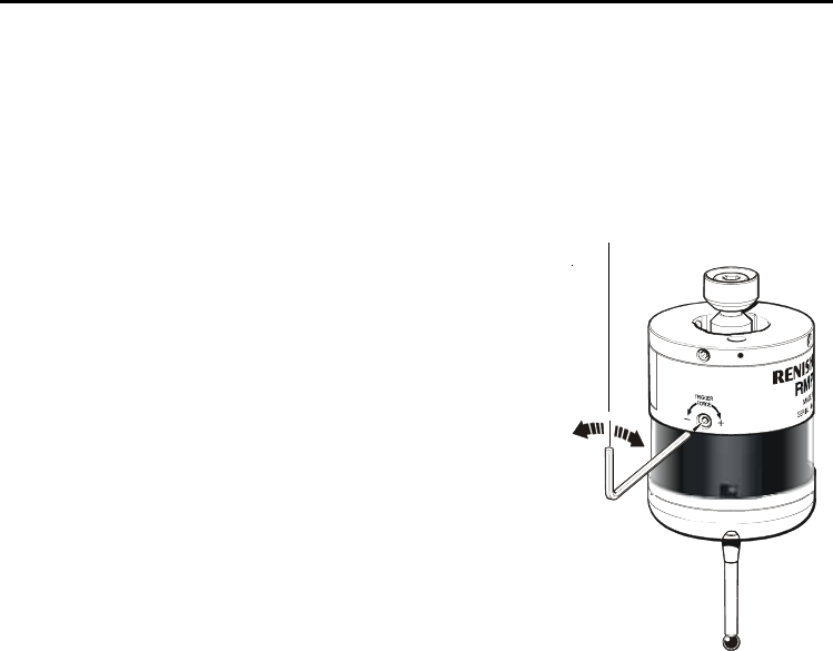
Stylus trigger force and adjustment
Stylus trigger force and adjustment
Spring force within the probe causes the stylus to sit in a unique
position, and return to this position following each stylus deflection.
Stylus trigger force is set by Renishaw. The user should only
adjust the trigger force in special circumstances, e.g. excessive
machine vibration or insufficient force to support the stylus weight.
To adjust the trigger force, turn the adjusting screw anticlockwise
to reduce force (more sensitive) or clockwise to increase
force (less sensitive). A stop prevents damage, which
could be caused by over-tightening the adjusting screw.
2 mm AF
Reduce
force
Increase
force
Stylus trigger force
Z direction
5.30 N / 530 gf (18.69 ozf)
X/Y direction (50 mm stylus)
X/Y trigger forces vary, depending on trigger direction.
There are 3 high force and 3 low force X/Y directions:
Factory setting for low force direction = 0.75 N / 75 gf (2.6 ozf)
Factory setting for high force direction = 1.4 N / 140 gf (4.9 ozf)
Maximum setting for low force direction = 2 N / 200 gf (7.0 ozf)
Maximum setting for high force direction = 3.5 N / 350 gf (12.3 ozf)
Minimum setting for low force direction = 0.5N / 50 gf (1.7 ozf)
Minimum setting for high force direction = 0.9 N / 90 gf (3.2 ozf)

31
Diaphragm replacement
Diaphragm replacement
RMP60 DIAPHRAGMS
The probe mechanism is protected from coolant
and debris by two diaphragms. These provide
adequate protection under normal working
conditions.
The user should periodically check the outer
diaphragm for signs of damage. If this is evident,
replace the outer diaphragm.
The user must not remove the inner diaphragm.
If damaged, return the probe to your supplier.
OUTER DIAPHRAGM INSPECTION
1. Remove the stylus.
2. Undo the three M3 front cover screws and
remove the front cover.
3. Inspect the outer diaphragm for damage.
4. To remove the outer diaphragm, grip by the
outer edge and pull off.
INNER DIAPHRAGM INSPECTION
5. Inspect the inner diaphragm for damage.
If damaged return the probe to your supplier.
DO NOT REMOVE THE INNER DIAPHRAGM
AS THE WARRANTY WILL BE VOID.
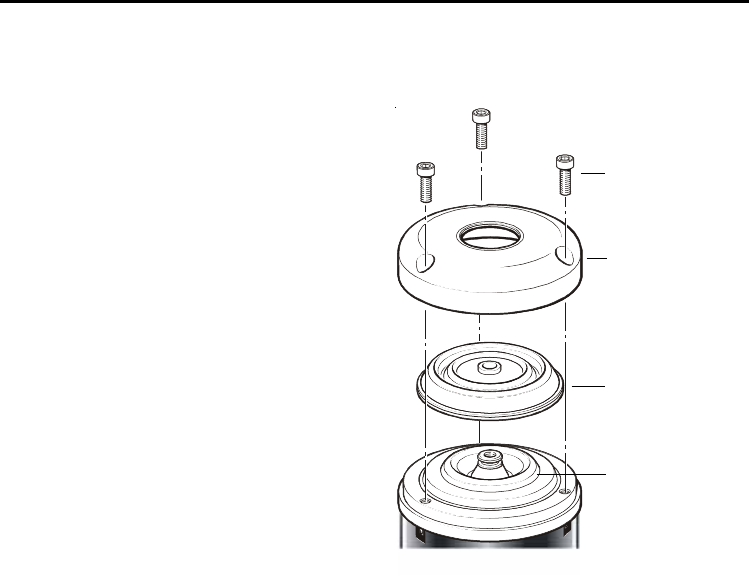
32 Diaphragm replacement
M3 screw
2.5 mm AF
1 Nm
(0.74 lbf.ft)
Cover
Outer
diaphragm
OUTER DIAPHRAGM REPLACEMENT
6. Fit the new diaphragm over centre.
7. Locate the outer edge of the diaphragm to
rest on the outer edge of the inner
diaphragm.
8. Refit the front cover and the M3 screws.
9. Refit the stylus and re-calibrate the probe.
Inner
diaphragm
33
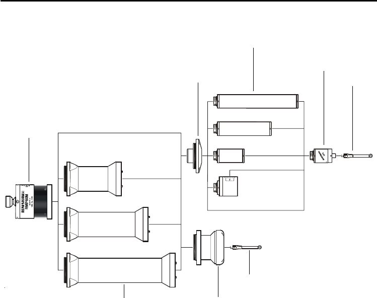
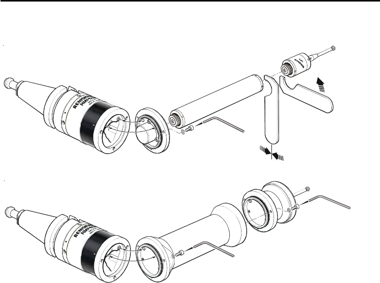
RMP60M system
RMP60M system
RMP60M is a special modular version
of RMP60. It enables probe inspection
of part features inaccessible to RMP60,
by fitting selected adaptors and
extensions as shown.
RMP60M
module
RMP60M extension
RMP60M
LP2 adaptor
RMP60M probe module
LPE extension bar
MA4 90°
adaptor
LP2 probe
M4
stylus
M4 stylus
see parts list
34
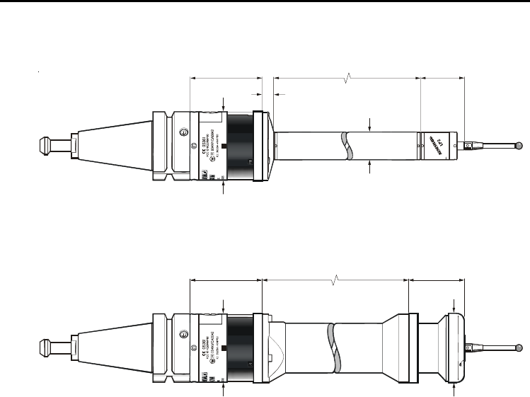
RMP60M dimensions
RMP60M dimensions
dimensions mm (in)
66,25
(2.61)
12,50 (0.49)
Ø63,00
(Ø2.48)
Ø25,00
(Ø0.98)
40,75
(1.60)
66,25
(2.61)
50,00 / 100,00 / 150,00
(1.97) / (3.94) / (5.91)
50,50
(1.99)
Ø63,00
(Ø2.48)
Ø63,00
(Ø2.48)
100,00 / 150,00 / 200,00
(3.94) / (5.91) / (7.88)
35
RMP60M screw torque values
2,6 Nm
(1.92 lbf.ft)
2,6 Nm
(1.92 lbf.ft)
2,6 Nm
(1.92 lb. ft)
10 Nm - 12 Nm
(7.37 lbf.ft - 8.84 lbf.ft)
RMP60M screw torque values

36 Fault-finding
Fault finding - If in doubt, consult your probe supplier.
Dead batteries.
Batteries incorrectly
inserted.
Probe out of range
No RMI ‘start/stop’ signal
(radio-on mode only)
Incorrect spin speed
(spin switch on only).
Malfunctioning shank switch
(shank switch mode only).
Incorrect switch on method
configured.
Incorrect Multiple Probe Mode
setting configured
RMP60 in hibernate mode
(radio-on mode only).
RMP60 fails to switch on. Change batteries.
Check/change batteries.
Check position of RMI,
see Operating envelope.
Check RMI for green start LED.
Check spin speed.
Check switch operation.
Check configuration and alter
as required.
Check configuration and alter
as required.
Ensure probe is in range
and wait up to 30 seconds.
Check position of RMI,
see Operating envelope.
Sympton Cause Action

37
Fault-finding
RMP60 fails to switch off.
RMP60 status LEDs
continuous red.
Poor battery life.
Incorrect switch off method
configured.
No RMI ‘start/stop’ signal
(radio on mode only)
Probe in time out mode and
placed in tool magazine and is
being triggered by movement.
Malfunctioning shank switch
(shank switch mode only).
Incorrect spin speed
(spin switch on only).
Dead batteries.
Radio link failure – RMP out
of RMI range.
RMI power has been removed.
Local radio interference.
Check configuration and alter as
required.
Check RMI for green start LED.
Review use of time out mode.
Increase spring force.
Check switch operation.
Check spin speed.
Change batteries.
Check position of RMI,
see Operating envelope.
Check power to RMI, leave
RMI powered all the time.
Identify source and move it
away from the RMP60 and RMI.
Symptom Cause Action

38 Fault-finding
Probe crash.
RMP60 status LEDs do
not correspond to RMI
status LEDs.
RMP60 probe status
LED continually lit red.
Review program.
Review installation.
Review probe software.
Review program.
Check position of RMI,
see Operating envelope.
Review installation.
Partner RMP60 and RMI.
Change batteries.
Inspection probe using
tool setting probe signals.
Probe length offset
missing/incorrect.
Workpiece obstructing probe
path.
Radio link failure – RMP60
out of RMI range.
RMP60 has been
enclosed/shielded by metal.
RMP60 and RMI are not
partnered.
Dead batteries.
Symptom Cause Action

39Fault-finding
RMI error LED lit during
probing cycle.
RMI error LED illuminated
during intended probe cycle.
RMI low battery LED lit.
Reduced range.
Poor repeatability.
Symptom Cause Action
Probe timed out.
Probe out of range.
Probe not switched on.
Probe out of range.
Low batteries.
Local radio interference.
Probing occurs within
machine’s acceleration/
deceleration zones.
Probe feedrate too high.
Temperature variation.
Wear in machine tool.
Change setting.
Review turn off method.
Check position of RMI,
see Operating envelope.
Check configuration and
alter as required.
Check position of RMI,
see Operating envelope.
Change batteries soon.
Identify and move.
Review probe software.
Check feedrate and correct,
test at different speeds.
Minimise temperature change.
Calibrate more frequently.
Calibrate just before use.
Perform health check on
machine.

40 Fault-finding
Poor measurement
results.
Symptom Cause Action
Debris on part or stylus.
Repeatability of probe
into spindle.
Loose probe to shank
mounting or stylus.
Offsets not being updated.
Calibrated feature has moved.
Measurement occurs as
stylus leaves surface.
Calibration and probing
speeds different.
Clean and recalibrate.
Verify by repeated toolchange
and single point move.
Check and tighten as
required, recalibrate.
Review software.
Check.
Review software.
Review software.

41
RMP60 A-4113-0001 RMP60 probe with batteries, tool kit and user’s guide
(set to radio on/radio off).
Battery P-BT03-0005 AA batteries - Alkaline - supplied as standard with probe
(two required).
Battery P-BT03-0008 AA batteries - Lithium thionyl chloride (two required).
Stylus A-5000-3709 PS3-1C ceramic stylus 50 mm long with Ø6 mm ball.
Weak link kit A-2085-0068 Weak link (Part no. M-2085-0069 (x 2) and
5 mm AF spanner.
TK A-4038-0304 Probe tool kit comprising: Ø1.98 mm stylus tool,
2.0 mm AF hexagon key 2.5 mm AF hexagon key (x 2),
4 mm AF hexagon key, shank grub screws (x 2),
weak link and 5 mm AF spanner.
Diaphragm kit A-4038-0302 RMP60 outer diaphragm.
Battery cassette A-4038-0300 RMP60 battery cassette assembly.
Cassette seal A-4038-0301 Battery cassette housing seal.
Parts list - Please quote the Part no. when ordering equipment.
Parts list
Type Part no. Description

42
Bobbin A-4038-0303 Bobbin for shank switch.
RMI A-4113-0050 RMI, side exit, with 15 m (49.2 ft) cable, tool kit and
User’s guide.
Mtg brkt A-2033-0830 Mounting bracket with fixing screws, washers and nuts.
Styli — For complete listing, please see Renishaw Styli guide.
Part no. H-1000-3200.
Software — For complete listing of Renishaw software for machine,
tools please see data sheets. Part no. H-2000-2289 and
H-2000-2298.
Shanks — For complete listing, please see Renishaw data sheet
H-2000-2011.
Parts list
Type Part no. Description

43Parts list
Type Part no. Description
RMP60M module A-4113-1003 RMP60M module with batteries, tool kit and User’s guide.
(set to radio on/radio off).
Extension L100 A-4038-1010 RMP60M extension - 100 mm long.
Extension L150 A-4038-1027 RMP60M extension - 150 mm long.
Extension L200 A-4038-1028 RMP60M extension - 200 mm long.
Probe module A-4038-1002 RMP60M probe module assembly.
RMP60M/LP2 A-4038-0212 RMP60M LP2 adaptor assembly
LPE1 A-2063-7001 LPE1 extension bar - 50 mm long.
LPE2 A-2063-7002 LPE2 extension bar - 100 mm long.
LPE3 A-2063-7003 LPE3 extension bar - 150 mm long.
MA4 A-2063-7600 MA4 90° adaptor assembly.

Switch-on method
Switch-off method
Multiple probe mode
Radio on
Shank on
Spin on
Radio or spin
Short timeout
12 seconds
Medium timeout
33 seconds
Long timeout
134 seconds
Off (factory set)
On (machine number)
RMP60 serial no.
--------------------------------------------------------------------------
Probe settings record table ✔ tick 44

Renishaw plc
New Mills, Wotton-under-Edge,
Gloucestershire, GL12 8JR
United Kingdom
T+44 (0)1453 524524
F+44 (0)1453 524901
Euk@renishaw.com
www.renishaw.com
For worldwide contact details,
please visit our main web site at
www.renishaw.com/contact
*H-2000-5219-05*