Renishaw plc RTS RTS Radio Tool Setter User Manual Manual
Renishaw plc RTS Radio Tool Setter Manual
Contents
- 1. Manual
- 2. Manual QSG
Manual

RTS radio tool setter
Installation guide
H-5646-8504-01-A (BETA SITE VERSION)

Renishaw part no: H-5646-8504-01-A
First issued: BETA SITE VERSION
© 2011 Renishaw plc. All rights reserved.
This document may not be copied or reproduced
in whole or in part, or transferred to any other
media or language, by any means, without the
prior written permission of Renishaw plc.
The publication of material within this document
does not imply freedom from the patent rights of
Renishaw plc.

Contents
Contents
Before you begin .................................................. 1.1
Before you begin ............................................................1.1
Disclaimer ..............................................................1.1
Trademarks .............................................................1.1
Warranty ................................................................1.1
Changes to equipment .....................................................1.1
CNC machines ...........................................................1.1
Care of the probe .........................................................1.1
Patents .................................................................1.2
EC declaration of conformity ...................................................1.3
WEEE directive .............................................................1.3
FCC declaration (USA) .......................................................1.3
Radio approval .............................................................1.4
Safety ....................................................................1.5
Information to the user .....................................................1.5
Information to the machine supplier / installer ...................................1.5
Information to the equipment installer .........................................1.5
Equipment operation ......................................................1.5
RTS basics ...................................................... 2.1
Introduction ................................................................2.1
Getting started .............................................................. 2.1
System interface ............................................................2.1
Trigger Logic™ .............................................................2.1
Modes of operation ..........................................................2.1
Configurable settings ......................................................... 2.2
Enhanced trigger filter .....................................................2.2
Acquisition mode .........................................................2.2
Switch-on ...............................................................2.2

RTS installation guide
ii
Contents
Operation .................................................................. 2.3
Software routines .........................................................2.3
Achievable set-up tolerances ................................................2.3
Recommended rotating tool feed rates ........................................2.3
RTS dimensions ............................................................2.4
RTS specification ...........................................................2.5
Typical battery life ......................................................... 2.5
System installation ................................................ 3.1
Installing the RTS with an RMI .................................................3.1
Operating envelope .......................................................3.1
Installing the RTS with an RMI-Q ...............................................3.2
Operating envelope .......................................................3.2
Performance envelope when using the RTS with an RMI/RMI-Q .......................3.3
RTS – RMI/RMI-Q positioning ...............................................3.3
Performance envelope .....................................................3.3
Preparing the RTS for use ..................................................... 3.4
Fitting the stylus, break stem and captive link ...................................3.4
Installing the batteries .....................................................3.5
Mounting the RTS on a machine table .........................................3.6
Stylus level setting ........................................................3.7
Square stylus only ........................................................3.9
Calibrating the RTS .........................................................3.13
Why calibrate a probe? ...................................................3.13
Trigger Logic™ ................................................... 4.1
Reviewing the current probe settings ............................................4.1
Changing the probe settings ...................................................4.2
RTS – RMI/RMI-Q partnership .................................................4.3
Operating mode ............................................................. 4.4
Probe status LEDs ........................................................4.4
Maintenance ...................................................... 5.1
Maintenance ...............................................................5.1
Cleaning the probe ..........................................................5.1
Changing the batteries .......................................................5.2
Battery types ...............................................................5.3
Routine maintenance ........................................................5.4
Inspecting the inner diaphragm seal .............................................5.5
Fault finding ...................................................... 6.1
Parts list ......................................................... 7.1

1.1
Before you begin
Disclaimer
RENISHAW HAS MADE CONSIDERABLE
EFFORTS TO ENSURE THE CONTENT OF THIS
DOCUMENT IS CORRECT AT THE DATE OF
PUBLICATION BUT MAKES NO WARRANTIES
OR REPRESENTATIONS REGARDING
THE CONTENT. RENISHAW EXCLUDES
LIABILITY, HOWSOEVER ARISING, FOR ANY
INACCURACIES IN THIS DOCUMENT.
Trademarks
RENISHAW® and the probe emblem used in the
RENISHAW logo are registered trademarks of
Renishaw plc in the UK and other countries.
apply innovation and Trigger Logic are
trademarks of Renishaw plc.
All other brand names and product names used
in this document are trade names, service marks,
trademarks, or registered trademarks of their
respective owners.
Warranty
Equipment requiring attention under warranty
must be returned to your equipment supplier.
No claims will be considered where Renishaw
equipment has been misused, or where
repairs or adjustments have been attempted by
unauthorised persons. Prior consent must be
obtained in instances where Renishaw equipment
is to be substituted or omitted. Failure to comply
with this requirement will invalidate the warranty.
Changes to equipment
Renishaw reserves the right to change equipment
specifications without notice.
CNC machines
CNC machine tools must always be operated by
fully trained personnel in accordance with the
manufacturer's instructions.
Care of the probe
Keep system components clean and treat the
probe as a precision tool.
Before you begin

RTS installation guide
1.2
Before you begin
Patents
Features of the RTS probe, and other similar
Renishaw probes, are the subject of one or more
of the following patents and/or patent applications:
CN CN100466003C
CN CN101287958A
CN CN101482402A
EP 0652413
EP 0695926
EP 0967455
EP 1373995
EP 1425550 B
EP 1457786
EP 1576560
EP 1701234
EP 1734426
EP 1804020
EP 1931936
EP 1988439
EP 2214147
EP 2216761
IN 2004/057552
IN 2004/057552
IN 2007/028964
IN 215787
JP 2004-279,417
JP 2004-522,961
JP 2008-203270
JP 2009-507240
JP 3,126,797
JP 4237051
JP 4398011
JP 4575781
TW 200720626
US 2006/0215614A1
US 5,279,042
US 5,669,151
US 6,275,053 B1
US 6,941,671 B2
US 7145468B2
US 7285935
US 7486195
US 7665219
1.3
Before you begin
C
FCC declaration (USA)
FCC Section 15.19
This device complies with Part 15 of the FCC
rules.
Operation is subject to the following two
conditions:
1. This device may not cause harmful
interference.
2. This device may accept any interference
received, including interference that may
cause undesired operation.
FCC Section 15.21
The user is cautioned that any changes or
modifications not expressly approved by
Renishaw plc, or authorised representative could
void the user’s authority to operate the equipment.
EC declaration of conformity
Renishaw plc hereby declares that the RTS is in
compliance with the essential requirements and
other relevant provisions of Directive 1999/5/EC.
Contact Renishaw plc at www.renishaw.com/rts
for the full EC declaration of conformity.
WEEE directive
The use of this symbol on Renishaw products
and/or accompanying documentation indicates
that the product should not be mixed with
general household waste upon disposal. It is the
responsibility of the end user to dispose of this
product at a designated collection point for waste
electrical and electronic equipment (WEEE) to
enable reuse or recycling. Correct disposal of
this product will help to save valuable resources
and prevent potential negative effects on the
environment. For more information, please contact
your local waste disposal service or Renishaw
distributor.

RTS installation guide
1.4
Before you begin
Radio approval
Europe:
USA:
Japan:
China:
Canada:
Australia:
New Zealand:
Switzerland:
Norway:

1.5
Before you begin
Safety
Information to the user
The RTS is supplied with two non-rechargeable AA
alkaline batteries. Once the charge in these batteries
is depleted, please dispose of them in accordance
with your local environmental and safety laws. Do
not attempt to recharge these batteries.
Please ensure replacement batteries are of the
correct type and are fitted with the correct polarity
in accordance with the instructions in this manual,
and as indicated on the product. For specific
battery operating, safety and disposal guidelines,
please refer to the battery manufacturers'
literature.
• Ensure that all batteries are inserted with
the correct polarity.
• Do not store batteries in direct sunlight or
rain.
• Do not heat or dispose of batteries in a fire.
• Avoid forced discharge of the batteries.
• Do not short-circuit the batteries.
• Do not disassemble, pierce, deform or apply
excessive pressure to the batteries.
• Do not swallow the batteries.
• Keep the batteries out of the reach of
children.
• Do not get batteries wet.
If a battery is damaged, exercise caution when
handling it.
The RTS has a glass window. Handle with care if
broken to avoid injury.
Information to the machine supplier/
installer
It is the machine supplier's responsibility to ensure
that the user is made aware of any hazards
involved in operation, including those mentioned
in Renishaw product literature, and to ensure
that adequate guards and safety interlocks are
provided.
Under certain circumstances, the probe signal
may falsely indicate a probe seated condition. Do
not rely on probe signals to halt the movement of
the machine.
Information to the equipment installer
All Renishaw equipment is designed to comply
with the relevant EC and FCC regulatory
requirements. It is the responsibility of the
equipment installer to ensure that the following
guidelines are adhered to, in order for the product
to function in accordance with these regulations:
• any interface MUST be installed in a
position away from any potential sources
of electrical noise, i.e. power transformers,
servo drives etc;
• all 0V/ground connections should be
connected to the machine "star point" (the
"star point" is a single point return for all
equipment ground and screen cables).
This is very important and failure to adhere
to this can cause a potential difference
between grounds;
• all screens must be connected as outlined in
the user instructions;
• cables must not be routed alongside high
current sources, i.e. motor power supply
cables etc, or be near high speed data lines;
• cable lengths should always be kept to a
minimum.
Equipment operation
If this equipment is used in a manner not specified
by the manufacturer, the protection provided by
the equipment may be impaired.

RTS installation guide
1.6
Before you begin
This page left intentionally blank

2.1
Introduction
The RTS is a tool setter with radio transmission
suitable for use on small to large machining
centres, or where line-of-sight between probe and
receiver is difficult to achieve.
The RTS forms part of Renishaw’s family of new
generation radio transmission probes. It has been
designed to comply with worldwide standards
and operates in the 2.4 GHz band. It delivers
interference-free transmission through the use of
FHSS (Frequency Hopping Spread Spectrum).
This allows many systems to operate in the same
machine shop without risk of cross-interference.
All RTS settings are configured using Trigger
Logic™. This technique enables the user to
review and subsequently change probe settings
by deflecting the stylus whilst observing the LED
indication.
Getting started
A multicolour LED provides visual indication of
selected probe states:
• trigger filter setting;
• tool setter status - triggered or seated;
• battery condition.
Batteries are inserted or removed as shown in
Section 5, "Maintenance" page 5.2.
On insertion of the batteries, the LED will begin
to flash (see Section 4, "Trigger Logic™" page
4.1).
System interface
The RMI and RMI-Q are combined antenna,
interface and receiver units used to communicate
between the RTS and the machine controller.
Trigger Logic™
All RTS settings are configured using the Trigger
Logic™ technique.
Trigger Logic™ (see Section 4, "Trigger
Logic™") is a method that allows the user to
view and select all available mode settings in
order to customise a probe to suit a specific
application. Trigger Logic™ is activated by battery
insertion and uses a sequence of stylus deflection
(triggering) to systematically lead the user through
the available choices to allow selection of the
required mode options.
Current probe settings can be reviewed by
simply removing the batteries for a minimum of
5 seconds, and then replacing them to activate
the Trigger Logic™ review sequence.
Modes of operation
The RTS can be in one of three modes:
Standby mode: where the RTS is awaiting a
switch-on signal.
Operational mode: activated by the switch-on
method described on the next page, the RTS is
ready for use.
Configuration mode: where Trigger Logic™ may
be used to configure the following probe settings.
RTS basics

RTS installation guide
2.2
RTS basics
Configurable settings
Enhanced trigger filter
Probes subjected to high levels of vibration or
shock loads may trigger without having been
contacted. The enhanced trigger filter improves
the probe’s resistance to these effects.
When the filter is enabled, a constant nominal
6.7 ms delay is introduced to the probe output.
It may be necessary to reduce the approach
speed to allow for the increased stylus overtravel
during the extended time delay. The RTS is factory
set to Enhanced trigger filter off.
Acquisition mode
System set-up is achieved using Trigger Logic™
and powering on the RMI or RMI-Q.
Partnering is only required during initial system
set-up. Further partnering is only required if either
the RTS or RMI/RMI-Q is changed.
Partnering will not be lost by reconfiguration of
probe settings or when changing batteries.
Partnering can take place anywhere within the
operating envelope.
Switch-on
When the RTS is used with an RMI the turn-on
time is 1.0 second. When the RTS is used with an
RMI-Q the turn-on time can be configured, in the
RMI-Q, to either 0.5 seconds or 1.0 second. For
best battery life, select 1.0 second turn-on time.
A timer automatically switches the probe off
90 minutes after the last trigger if not turned
off by an M code.
NOTE: After being switched on, the RTS must be
on for 1.0 second minimum before being switched
off.
2.3
RTS basics
Operation Recommended rotating tool feed rates
Cutters should be rotated in reverse to the
cutting direction. Renishaw tool setting software
calculates speeds and feeds automatically using
the following information.
First touch – machine spindle rev/min
Rev/min for the first move against the probe
stylus:
Diameters below 24 mm, 800 rev/min is used.
Diameters from 24 mm to 127 mm, rev/min is
calculated using a surface speed of 60 m/min
(197 ft/min).
Diameters above 127 mm, 150 rev/min is used.
First touch – machine feed rate
The feedrate (f) is calculated as follows:
f = 0.16 × rev/min f units mm/min (diameter set)
f = 0.12 × rev/min f units mm/min (length set)
Second touch – machine feed rate
800 rev/min, 4 mm/min (0.16 in/min) feedrate.
The tool is driven in the machine Z axis for tool
length measurements and broken tool detection.
Rotating tools are set in the machine’s X and Y
axes for tool radius offsets.
Screw adjusters allow the stylus to be aligned with
the machine’s axes.
Software routines
Software routines for tool setting are available
from Renishaw for various machine controllers
and are described in data sheet H-2000-2289.
In addition, data sheet H-2000-2298 lists available
Renishaw software programs. Both data sheets
can be downloaded from www.renishaw.com/
inspectionplus.
Achievable set-up tolerances
The tolerances to which tools can be set depend
upon the flatness and parallelism of the stylus tip
setting. A value of 5 µm (0.0002 in) front to back
and side to side is easily achievable over the flat
portion of the stylus tip, and 5 µm (0.0002 in)
parallelism is easily achievable with the axes of a
square tip stylus. This setting accuracy is sufficient
for the majority of tool setting applications.
Stylus
ZX/Y
Rotate tool in reverse direction
for diameter setting
X
Y
RTS installation guide
2.4
RTS basics
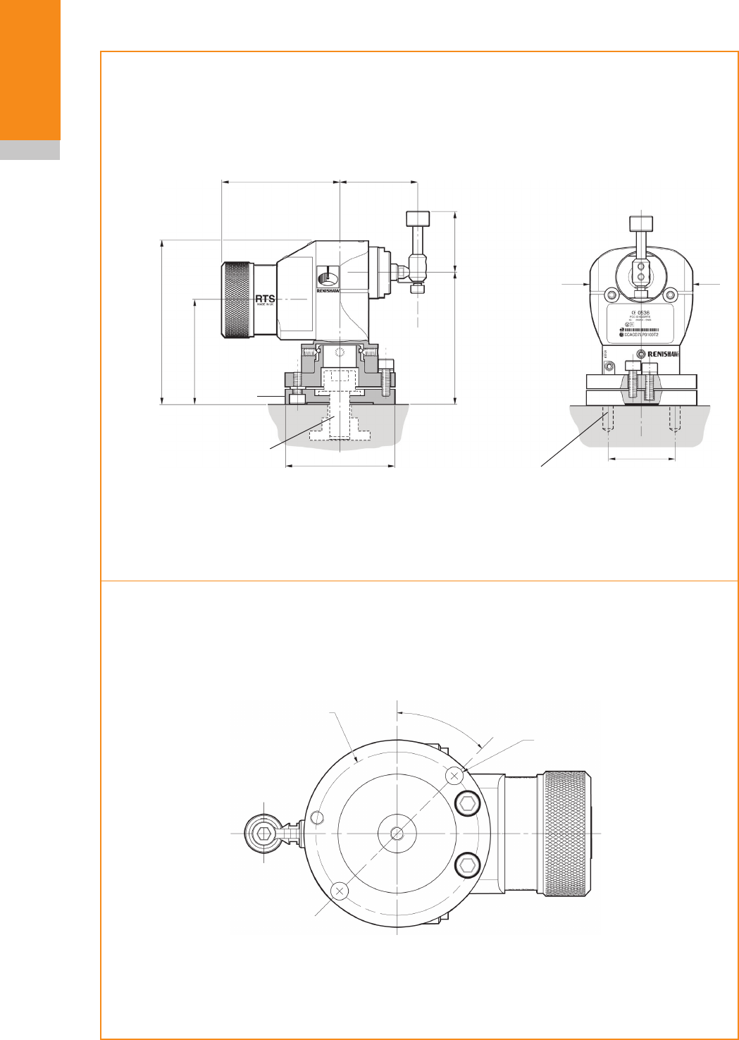
RTS dimensions
Dimensions given in mm (in)
Machining details for dowel pins
Machine table
Ø62.5 (2.46)
33 (1.30)
with square
and disc
stylus
44 (1.73)
Base
Ø54 (2.125)
Ø54 (2.125)
93.25 (3.67)
57.00 (2.24)
74.50 (2.93)
60
(2.36)
Two holes for dowel pins
6.13 (0.24)
5.95 (0.23)
equi-spaced on Ø54 (2.125) PCD at 45° to RTS axis
Øx 13 (0.51) deep MIN
Cap head bolt and T nut
M10/M12 (Ø0.50) MAX
Typical bolt length 30 (1.18)
supplied by user
66.05 (2.60)
M/C bed holes for dowel pins
6.13 (0.24)
5.95 (0.23) x 13 (0.51) deep MIN
45°
2 off Ø6 mm dowel pin holes
2.5
RTS basics
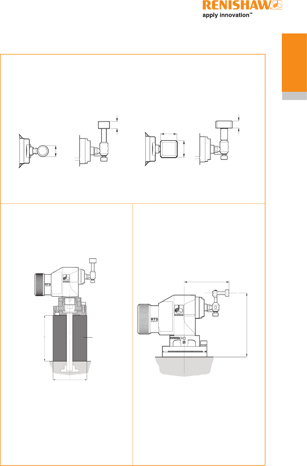
RTS dimensions (continued)
Ø65 (2.56)
Cranked horizontal stylus adaptor kit
Disc and square stylus
70.0 (2.76)
95.7 (3.77)
76.5 (30.12) shown
Typical bolt length 110 (4.3)
or
125.5 (4.94)
Typical bolt length 150 (5.9)
Raising block
Raising block
19.05 (0.75)
8 (0.31)
8 (0.31)
19.05 (0.75)
Disc stylus
Ø12.7 mm × 8 mm (Ø0.5 in × 0.31 in)
Tungsten carbide 75 Rockwell C
Square stylus
19.05 mm x 19.05 mm (0.75 in x 0.75 in)
Ceramic 75 Rockwell C
Ø12.7 (Ø0.5)

RTS installation guide
2.6
RTS basics
* Probe module results valid as tested with a 35 mm (1.38 in) straight stylus and a velocity of 480 mm/min (1.57 ft/min).
§ Specification using 50 mm (1.97 in) straight stylus.
RTS specification
Principal application Tool setting on CNC machining centres
Overall dimensions Length with disc stylus 116.40 mm (4.58 in)
Length with square stylus 119.58 mm (4.71 in)
Width 62.50 mm (2.46 in)
Height with disc and square
stylus
107.50 mm (4.23 in)
Weight (with disc stylus) With batteries
Without batteries
870 g (30.69 oz)
820 g (28.92 oz)
Transmission type Frequency hopping spread spectrum (FHSS) radio
Radio frequency 2400 MHz to 2483.5 MHz
Switch-on methods Radio M code
Switch-off methods Radio M code
Operating range Up to 15 m (49.2 ft)
Receiver/interface RMI or RMI-Q (combined antenna, interface and receiver unit)
Sense directions Omni-directional ±X, ±Y, +Z
Uni-directional
repeatability
1.0 µm (0.00004 µin) 2 sigma*
Stylus trigger force 1.3 N to 2.4 N/130 gf to 240 gf (4.5 ozf to 8.5 ozf) depending on the
sense direction. §
Stylus overtravel XY plane
+Z plane
± 3.5 mm (0.14 in)
6 mm (0.24 in)
Environment IP rating IPX8 (EN/IEC60529)
Storage temperature -25 °C to +70 °C (+13 °F to +158 °F)
Operating temperature +5 °C to +55 °C (+41 °F to +131 °F)
Battery types 2 x AA 1.5 V alkaline or 2 x AA 3.6 V Lithium Thionyl Chloride
Battery reserve life Approximately one week after a low battery warning is first given.
Typical battery life See table below
Low battery indication Blue flashing LED in conjunction with normal red or green probe
status LED
Dead battery indication Constant or flashing red
Battery type Standby life 5% usage
(72 minutes/day) Continuous use
Alkaline 270 days maximum 175 days maximum 540 hours
Lithium Thionyl Chloride 600 days maximum 400 days maximum 1,410 hours
Typical battery life
3.1
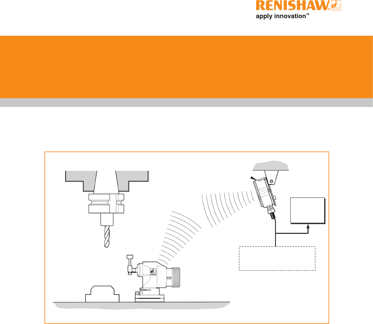
Installing the RTS with an RMI
CNC machining
centre spindle
RMI
interface RMI mounting
bracket
CNC
machine
control
Power supply
RTS probe
Cable
Workpiece
Stylus
System installation
Operating envelope
Radio transmission does not require line-of-
sight between the probe and transmitter and will
pass through very small gaps and machine tool
windows. This allows easy installation, either
inside or outside the machine enclosure, so long
as the probe and transmitter are kept within the
performance envelope specified and that the RMI
signal LED remains on at all times.
Coolant and swarf residue accumulating on the
RTS and RMI may have a detrimental effect
on transmission performance. Wipe clean as
often as is necessary to maintain unrestricted
transmission.
When in operation, do not touch either the RMI
cover or the RTS glass window with your hand as
this can also affect transmission performance.
Some reduction in range may result when
operating in temperatures of 0 °C to +5 °C
(+32 °F to +41 °F) and +50 °C to +60 °C
(+122 °F to +140 °F).
RTS installation guide
3.2
System
installation
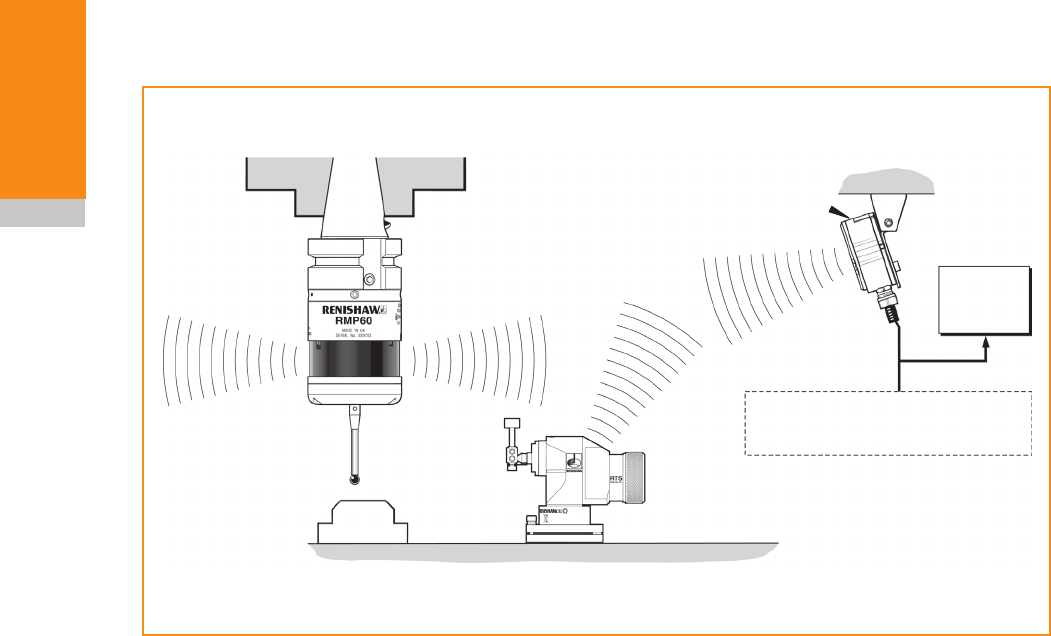
Installing the RTS with an RMI-Q
CNC machining
centre spindle
Typical inspection
probe
RMI-Q
interface Mounting
bracket
CNC
machine
control
Power supply
RTS probe
Cable
Workpiece
Stylus
Operating envelope
Radio transmission does not require line-of-
sight between the probe and transmitter and will
pass through very small gaps and machine tool
windows. This allows easy installation, either
inside or outside the machine enclosure, so long
as the probe and transmitter are kept within the
performance envelope specified and that the RMI
signal LED remains on at all times.
Coolant and swarf residue accumulating on the
RTS and RMI-Q may have a detrimental effect
on transmission performance. Wipe clean as
often as is necessary to maintain unrestricted
transmission.
When in operation, do not touch either the RMI-Q
cover or the RTS glass window with your hand as
this can also affect transmission performance.
Some reduction in range may result when
operating in temperatures of 0 °C to +5 °C
(+32 °F to +41 °F) and +50 °C to +60 °C
(+122 °F to +140 °F).
3.3
System
installation
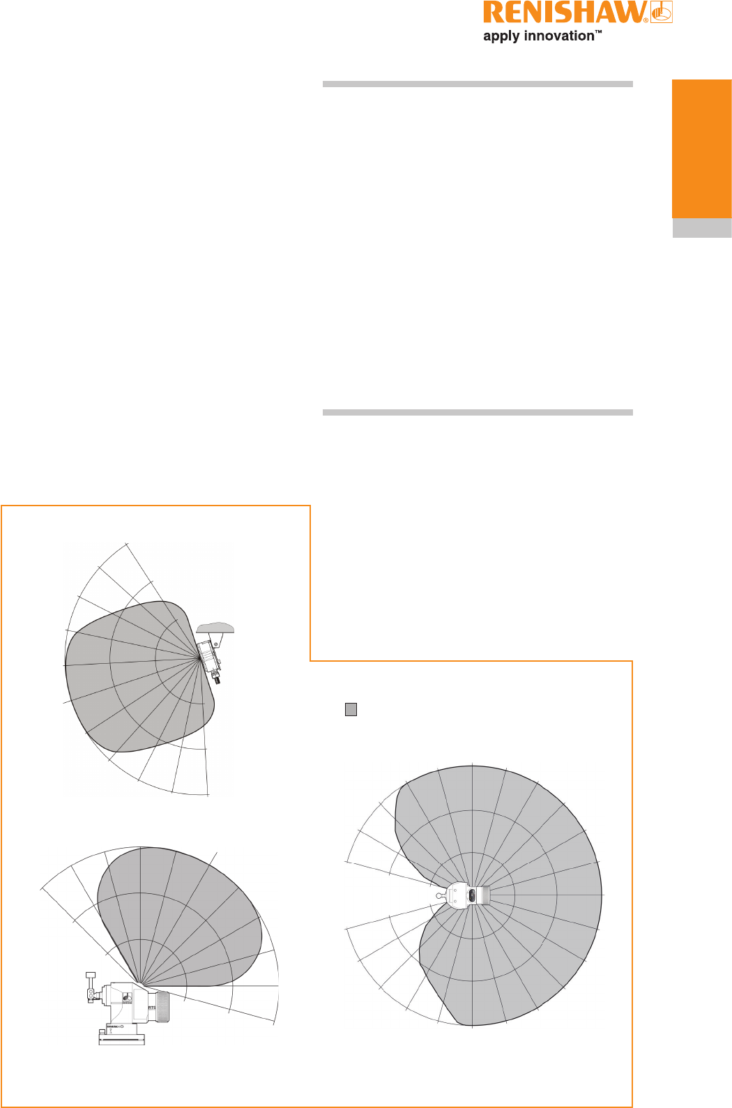
Performance envelope when
using the RTS with an RMI/RMI-Q
RTS - RMI/RMI-Q positioning
The probe system should be positioned so that
the optimum range can be achieved over the full
travel of the machine's axes. Always face the front
cover of the RMI/RMI-Q in the general direction
of the machining area and the tool magazine,
ensuring both are within the performance
envelope shown below. To assist in finding the
optimum position of the RMI/RMI-Q, the signal
quality is displayed on an RMI/RMI-Q signal LED.
Ensure that the signal LED indicates a green or
yellow (good) signal strength when the RTS is
operating or in stand-by mode (see following note
regarding 'hibernate mode').
NOTE: RMI/RMI-Q installation with RTS.
RTS has a built-in hibernate mode (battery saving
mode) that saves battery life when the RMI/RMI-Q
is unpowered. The RTS goes into hibernate mode
30 seconds after the RMI/RMI-Q is unpowered
(or the RTS is out of range). When in hibernate
mode, the RTS checks for a powered RMI/RMI-Q
every 30 seconds. If found, the RTS goes from
hibernate mode to stand-by mode, ready for an
M code. If the RTS goes out of range, for example
if the RTS is fitted to a pallet which is removed
from the machine, once the RTS is back in range
the system will automatically re-synchronise
within 30 seconds (worst case). Allowance must
be made within the machine controller program for
this.
Performance envelope
The RTS and RMI/RMI-Q must be within each
other's performance envelope as shown below.
The performance envelope shows line-of-sight
performance, however radio transmission does
not require this providing a reflected path (of less
than 15 m (49.2 ft)) is available.
0°
15°
15°
75°
75°
60°
60°
45°
45°
30°
30°
10 (33)
10 (33)
15 (49)
15 (49)
5 (16)
5 (16)
RTS SIDE VIEW
0°
15°
75°
60°
45°
30°
30°
45°
60° 75°
10 (33)
15 (49)
5 (16)
5 (16)
10 (33)
15 (49)
15°
RMI/RMI-Q
RTS TOP VIEW
5
(16)
10
(33)
15
(49)
75°
60°
45°
30°
15° 0° 15°
30°
30°
45°
60°
75°
90° 90°
75°
60°
45°
15°
45°
60°
75°
0°
15°
30°
Range metres (feet)
OPERATING AND SWITCH ON/OFF
RTS installation guide
3.4
System
installation
1
2
3
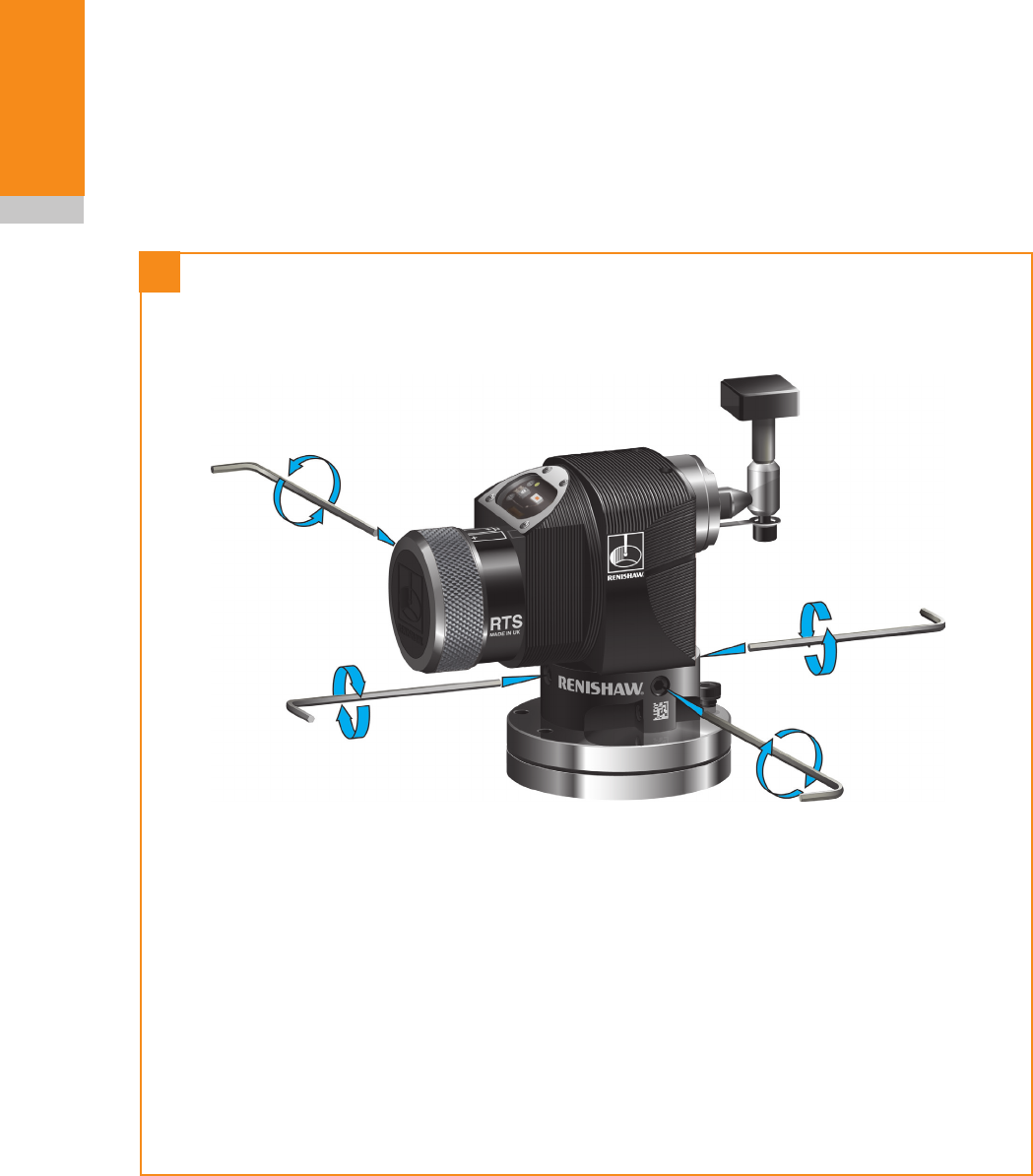
Preparing the RTS for use
Fitting the stylus, break stem and
captive link
5 mm AF (thin)
2.6 Nm
(1.92 lb.ft)
2 mm AF
1.1 Nm
(0.81 lb.ft)
2 mm AF
1.1 Nm
(0.81 lb.ft)
3 mm AF
2.6 Nm
(0.92 lb.ft)
Support bar
Break stem
Stylus
Captive link
Stylus weak link break stem
A stylus weak link break stem is incorporated
in the stylus mounting. This protects the probe
mechanism from damage in the event of
excessive stylus overtravel or a collision.
Captive link
In the event of the break stem breaking, the
captive link ties the stylus to the probe, which
prevents the stylus falling into the machine.
NOTE: Always hold the support bar in position
to counteract twisting forces and avoid over-
stressing the stylus break stem.
3.5
System
installation
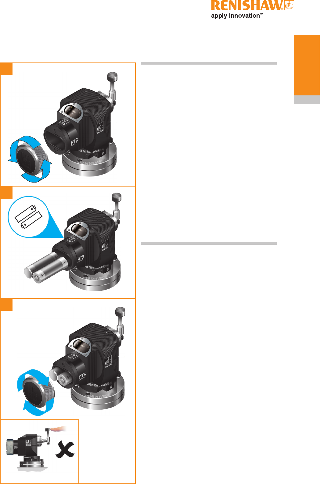
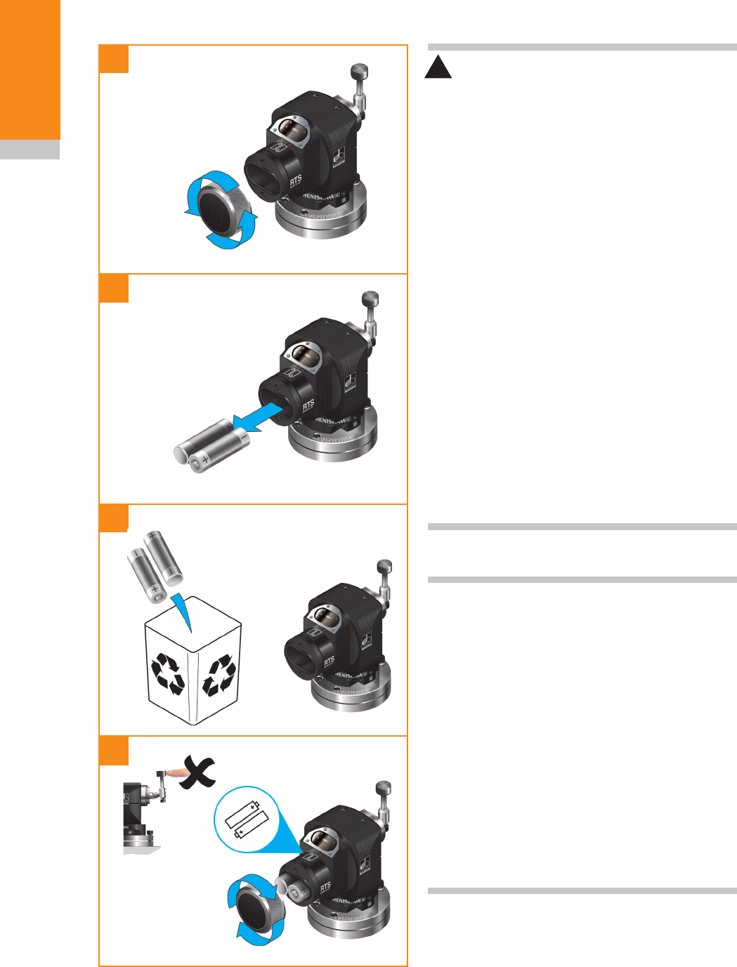
Installing the batteries
NOTES:
See Section 5, "Maintenance" for a list of
suitable battery types.
If dead batteries are inadvertently inserted into
the probe, the LED will remain a constant red
(for details, see Section 4, "Trigger Logic™"
page 4.4).
Ensure the product is clean and dry before
inserting batteries.
Do not allow coolant or debris to enter the battery
compartment.
When inserting batteries, check that the battery
polarity is correct.
After inserting the batteries, the LED will display
the current probe settings (for details, see
Section 4, "Trigger Logic™" page 4.1).
1
2
3
RTS installation guide
3.6
System
installation
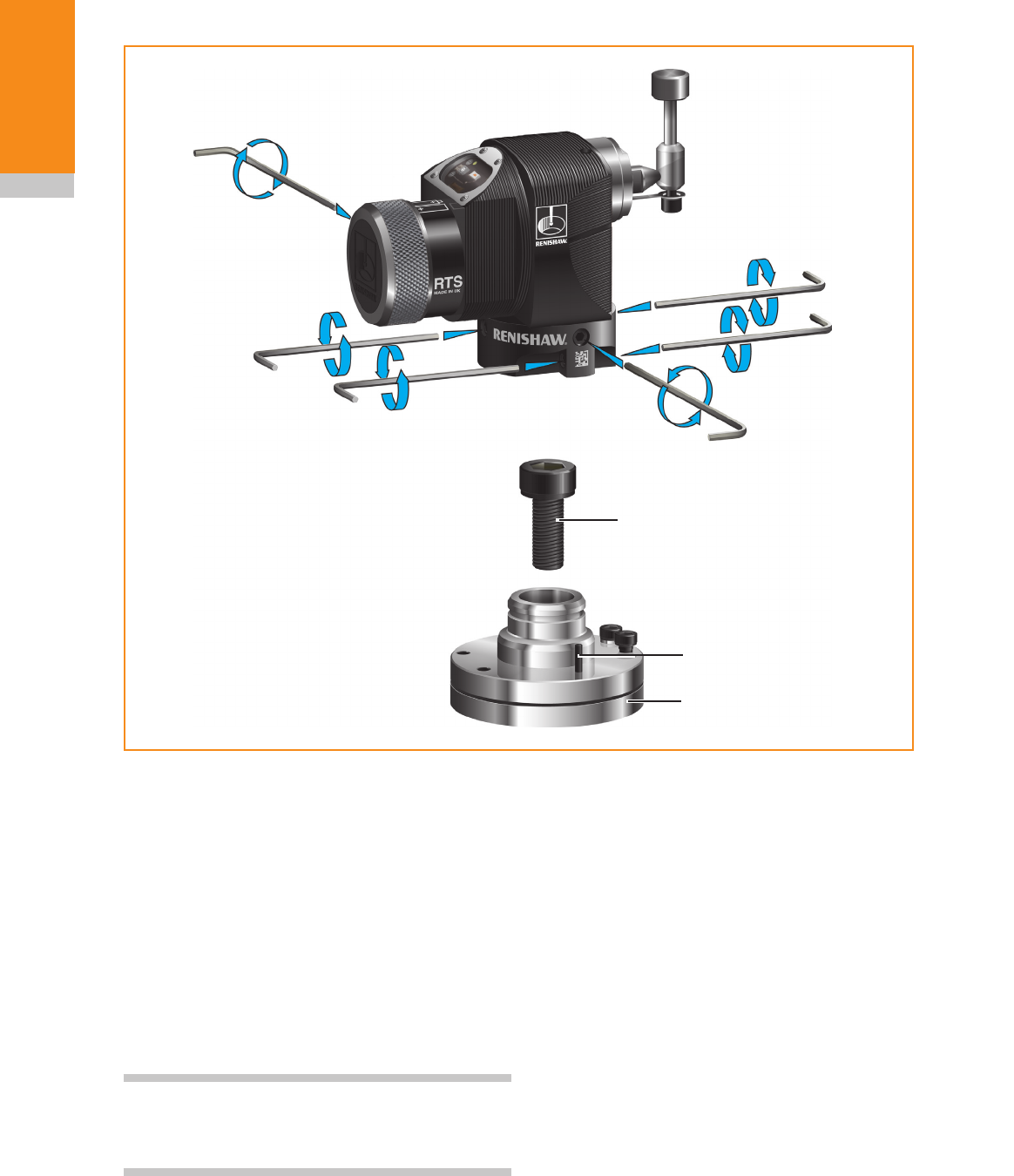
Mounting the RTS on a machine table
1. Select a position for the RTS on the
machine table. Position to minimise the
possibility of collision and ensure the radio
window faces towards the receiver.
2. Separate the base from the body by
slackening four screws 1 and two screws 2
using a 2.5 mm AF hexagon key.
3. Fit the cap head bolt and T nut (not supplied
by Renishaw) and tighten to secure the
base to the machine table.
NOTE: A smaller washer should be fitted for a
smaller bolt by disassembling and separating the
base plates.
4. Refit the body onto the base and tighten
screws 1 and 2. If a square stylus is
fitted, and fine rotational adjustment is
required, see "Square stylus only",
"Coarse rotational adjustment" and "Fine
rotational adjustment" pages 3.9 - 3.12
before tightening screws 2.
5. Fit the stylus. See "Fitting the stylus,
break stem and captive link" page 3.4.
Dowel pins (shown on page 2.4)
Two locating pins (supplied in the tool kit) may be
fitted on installations where there is a requirement
to remove and remount the tool setter.
To fit the dowel pins, drill two holes in the machine
table to correspond with the two probe base holes.
Place the dowel pins in the holes and refit the
probe base.
2.5 mm AF
1.1 Nm
(0.81 lb.ft)
2.5 mm AF
1.1 Nm
(0.81 lb.ft)
Locating pin
Base
M10 / M12 bolt and T nut
(not supplied)
1
1
1
1
2
2

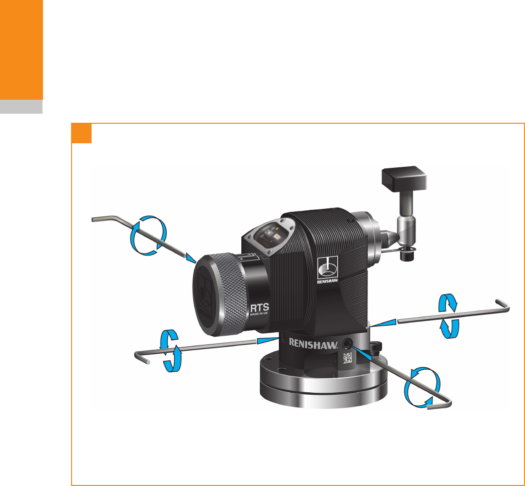
3.7
System
installation
2.5 mm AF
1.1 Nm
(0.81 lbf.ft)
Probe module
Stylus level setting
The top surface of the stylus must be set level,
front to back and side to side.
Side to side level adjustment
Side to side level adjustment is obtained by
alternately adjusting the grub screws provided,
which causes the probe module to rotate and
change the stylus level setting.
When a level stylus surface is obtained, tighten
the grub screws.
1

RTS installation guide
3.8
System
installation
Adjusting / locking screw
4 mm AF
5.1 Nm (3.76 lbf.ft)
Height adjusting
screw
4 mm AF
Stylus level setting (continued)
Front to back level adjustment
To raise the front
Slacken locking screw 2 and adjust height
adjusting screw 1 until the stylus is level. Then
fully tighten screw 2.
To lower the front
Keep slackening height adjusting screw 1 and
adjusting/locking screw 2 until the stylus is level.
Then fully tighten screw 2.
2
1
2

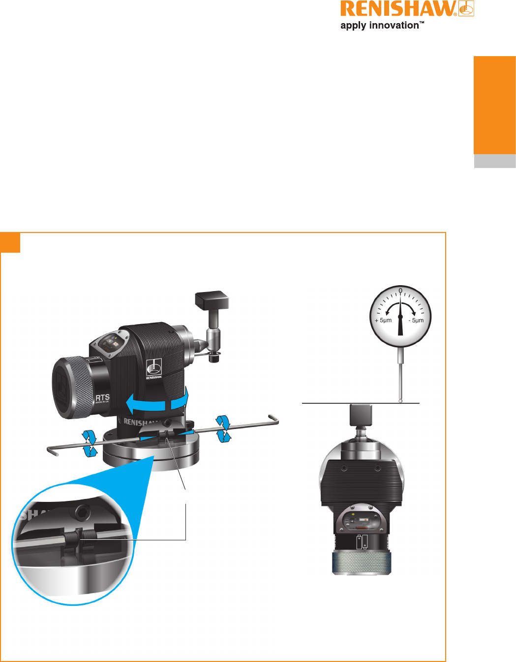
3.9
System
installation
Square stylus only
Square stylus rotational adjustment allows the
stylus to be aligned with the machine axes.
Coarse rotational adjustment
Slacken grub screw 1 and rotate the stylus by
hand to obtain alignment, then fully tighten the
grub screw.
NOTE: Always hold the support bar in position
to counteract twisting forces and avoid over-
stressing the stylus break stem.
2 mm AF
1.1 Nm
(0.81 lbf.ft)
Support bar
Stylus break stem
with captive link
3
1
4
RTS installation guide
3.10
System
installation
Square stylus only (continued)
Fine rotational adjustment
Slacken the four body locking screws 1.
1
1
1
1
3.11
System
installation
5
Locating pin
Square stylus only (continued)
Fine rotational adjustment (continued)
Opposing grub screws 2 are tightened against
a locating pin fixed to the base. By alternately
slackening and re-tightening these grub screws,
fine rotational adjustment of the stylus is achieved.
Then tighten the grub screws.
2.5 mm AF
1.1 Nm
(0.81 lbf.ft)
2
2
6
2.5 mm AF
0.8 Nm
(0.6 lbf.ft)
1
1
1
1
RTS installation guide
3.12
System
installation
Square stylus only (continued)
Fine rotational adjustment (continued)
Tighten the four body locking screws 1.

3.13
System
installation
Calibrating the RTS
Why calibrate a probe?
A probe is just one component of the
measurement system which communicates with
the machine tool. Each part of the system can
introduce a constant difference between the
position that the stylus touches, and the position
that is reported to the machine. If the probe is
not calibrated, this difference will appear as an
inaccuracy in the measurement. Calibration of the
probe allows the probing software to compensate
for this difference.
During normal use, the difference between the
touch position and the reported position does not
change but it is important that you calibrate your
probe in the following circumstances:
• when a probe system is to be used for the
first time;
• when a new stylus is fitted to the probe;
• when it is suspected that the stylus has
become distorted or that the probe has
crashed;
• at regular intervals to compensate for
mechanical changes of your machine tool.
When your probe is assembled and mounted
on the machine table, it is necessary to align
the stylus faces with the machine axes to avoid
probing errors when setting tools. It is worth taking
care with this operation – you should try to get the
faces aligned to within 0.010 mm (0.0004 in)
for normal use. This is achieved by manually
adjusting the stylus with the adjusting screws
provided, and using a suitable instrument such as
a DTI clock mounted in the machine spindle.
When the probe has been correctly set up on
the machine, it is time to calibrate the probe.
Calibration cycles are available from Renishaw
for this task. The purpose is to establish the probe
stylus measuring face trigger point values under
normal measuring conditions.
Calibration should be run at the same speed as
probing.
The calibration values are stored in macro
variables for computation of the tool size during
tool setting cycles.
Values obtained are axis trigger positions
(in machine co-ordinates). Any errors due to
machine and probe triggering characteristics
are automatically calibrated out in this way.
These values are the electronic trigger positions
under dynamic operating conditions, and
not necessarily the true physical stylus face
positions.
NOTE:
Poor repeatability of probe trigger point values
indicates that either the probe/stylus assembly
is loose or a machine/probe fault exists. Further
investigation is required.

RTS installation guide
3.14
System
installation
This page left intentionally blank
4.1
Trigger Logic™
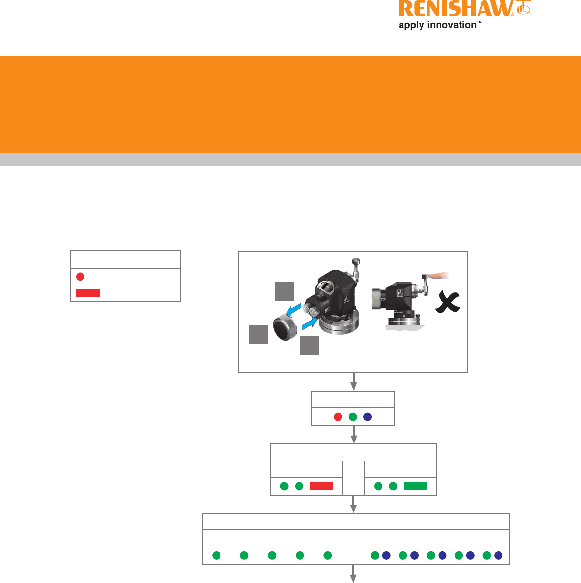
Reviewing the current probe settings
Probe in standby mode
Key to the symbols
LED short flash
LED long flash
> 5 s
1
23
LED check
Enhanced trigger filter
Off
or
On
Battery status
Battery good
or
Battery low
RTS installation guide
4.2
Trigger Logic™
New settings
complete
Return to
‘Enhanced trigger filter’
Insert batteries or, if already installed, remove for
5 seconds and replace. Following the LED check,
immediately deflect the stylus and hold deflected
until five red flashes have been observed (if the
battery power is low then each of the five red
flashes will be followed by a blue flash).
Keep the stylus deflected until the 'Enhanced
trigger filter' menu is displayed, then release the
stylus. The probe is now in configuration mode
and Trigger Logic™ is activated.
Changing the probe settings
Key to the symbols
LED short flash
LED long flash
Deflect the stylus.
Wait less than 4
seconds before
moving to next
menu option.
Deflect the stylus.
Wait more than 4
seconds before
moving to next
menu.
To exit, leave the
stylus untouched
for more than 20
seconds.
Deflect the stylus and hold deflected until after
the battery status has been displayed at the
end of the review sequence.
> 5 s
1
2
3
LED check
NOTE: To partner an RTS with an RMI/RMI-Q
please see "RTS – RMI/RMI-Q partnership"
page 4.3. Once acquisition has been successful,
the RTS will revert to "Acquisition mode off".
Battery status
Battery good
or
Battery low
Enhanced trigger filter
Off On
Acquisition mode
Acquisition mode
off
Acquisition mode
on
4.3
Trigger Logic™
RTS – RMI/RMI-Q partnership
System set-up is achieved using Trigger Logic™
and powering on the RMI/RMI-Q. Partnering is
only required during initial system set-up. Further
partnering is only required if either the RTS or
RMI/RMI-Q is changed.
Partnering will not be lost by reconfiguring the
probe settings or when changing batteries.
Partnering can take place anywhere within the
operating envelope.
In configuration mode, configure the probe
settings as required until you reach the
"Acquisition mode" menu, which defaults to
"Acquisition mode off".
Deflect the stylus to select 'Acquisition
mode on'. Ensure this is done within
10 seconds of the RMI/RMI-Q signal
LED flashing green.
SIGNAL LED
RMI/RMI-Q
in acquisition mode
3
3
The probe is in stand-by
and the system is ready
for use.
New partner RMP acquired
SIGNAL LED
> 20 s
Acquisition mode
off
Acquisition mode
Acquisition mode
on
Switch on the RMI/RMI-Q
NOTE: Once in ‘Acquisition
mode off’, ensure the next two
steps are completed within
20 seconds.
< 4 s
RTS installation guide
4.4
Trigger Logic™
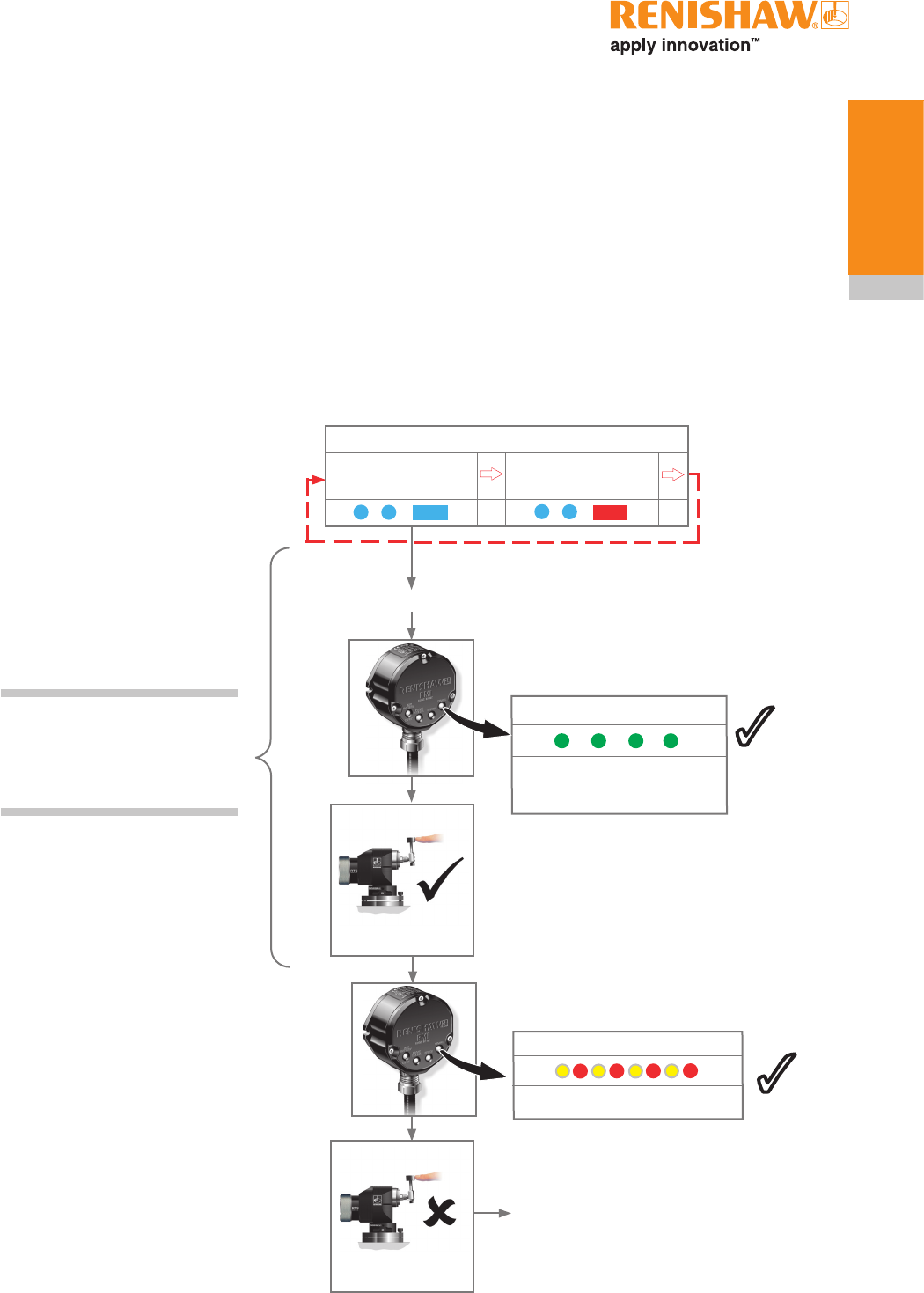
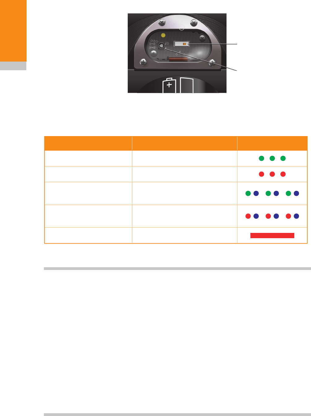
Operating mode
Multicoloured
probe status LED
LED colour Probe status Graphic hint
Flashing green Probe seated in operating mode
Flashing red Probe triggered in operating mode
Flashing green and blue Probe seated in operating mode -
low battery
Flashing red and blue Probe triggered in operating mode
- low battery
Constant red Battery dead
Antenna
Probe status LEDs
NOTES:
Due to the nature of Lithium Thionyl Chloride batteries, if a 'low battery' LED sequence is ignored
or overlooked, then it is possible for the following sequence of events to occur:
1. When the probe is active, the batteries discharge until battery power becomes too low for the
probe to operate correctly.
2. The probe stops functioning, but then re-activates as the batteries recover sufficiently to
provide the probe with power.
3. The probe begins to run through the LED review sequence, see page 4.1.
4. Again, the batteries discharge and the probe ceases to function.
5. Again, the batteries recover sufficiently to provide the probe with power and the sequence
repeats itself.

Maintenance
You may undertake the maintenance routines
described in these instructions.
Further dismantling and repair of Renishaw
equipment is a highly specialised operation,
which must be carried out at authorised
Renishaw Service Centres.
Equipment requiring repair, overhaul or attention
under warranty should be returned to your
supplier.
Cleaning the probe
Wipe window of probe with a clean cloth to
remove machining residue. This should be
done on a regular basis to maintain optimum
transmission.
5.1
Maintenance
RTS installation guide
5.2
Maintenance
CAUTIONS:
Do not leave exhausted batteries in the probe.
When changing batteries, do not allow coolant or
debris to enter the battery compartment.
Ensure product is clean and dry before inserting
batteries.
When changing batteries, check that the battery
polarity is correct.
Take care to avoid damaging the battery
compartment gasket.
Only use specified batteries (page 5.3).
Please dispose of exhausted batteries in
accordance with local regulations. Never dispose
of batteries in a fire.
Further battery safety information is available on
page 1.5.
Changing the batteries
1
2
4
3
!
NOTES:
Do not mix new and used batteries or battery
types as this will result in reduced life and
damage to the batteries.
Always ensure that the gasket and mating
surfaces are clean and free from dirt before
reassembly.
After removing old batteries wait more than
5 seconds before inserting new batteries.
If dead batteries are inadvertently inserted into
the probe then the LEDs will remain a constant
red.
5.3
Maintenance
H AA (1.5 V) Alkaline × 2 supplied with probe
All AA alkaline batteries
AA (3.6 V) Lithium Thionyl Chloride (LTC) × 2 (optional type)
Minamoto: ER14505, ER14505H
RS: 596-602, 201-9438,
324-6748
Radio shack: 55025148
Saft: LS14500, LS14500C
Tadiran: SL-360/S, SL-760/S,
SL-860/S,
TL-5903/S, TLH-5903/S
Tekcell: SS-AA11
Xeno: XL-060F
Maxell: ER6C
Minamoto: ER14505S
Tadiran: SL-560/S,
TL-4903/S
H AA battery types are also designated as LR6 or MN1500.
3
3
Battery types
RTS installation guide
5.4
Maintenance
Routine maintenance
The probe is a precision tool and must be
handled with care.
Ensure the probe is firmly secured to its
mounting.
The probe requires minimal maintenance as it is
designed to operate as a permanent fixture on
CNC machining centres, where it is subject to a
hot chip and coolant environment.
1. Do not allow excessive waste material to
build up around the probe.
2 Swarf accumulating on the transmission
window will have a detrimental effect on
transmission performance, see page 5.1.
3. Keep all electrical connections clean.
4. The probe mechanism is protected by an
outer metal eyelid seal and an inner flexible
diaphragm seal.
Approximately once a month, inspect the probe
inner diaphragm seal, see page 5.5. If it is
pierced or damaged please contact Renishaw.
The service interval may be extended or reduced
depending on experience.
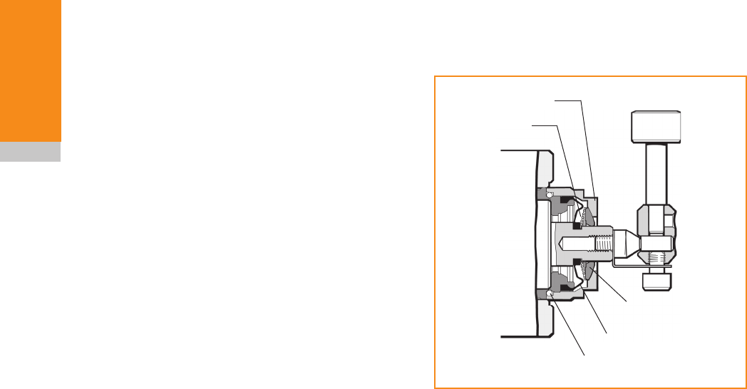
Spring
Front cover
O ring
Inner diaphragm seal
Metal eyelid seal
Probe
module
5.5
Maintenance
Inspecting the inner diaphragm
seal
1. Remove the stylus/break stem assembly
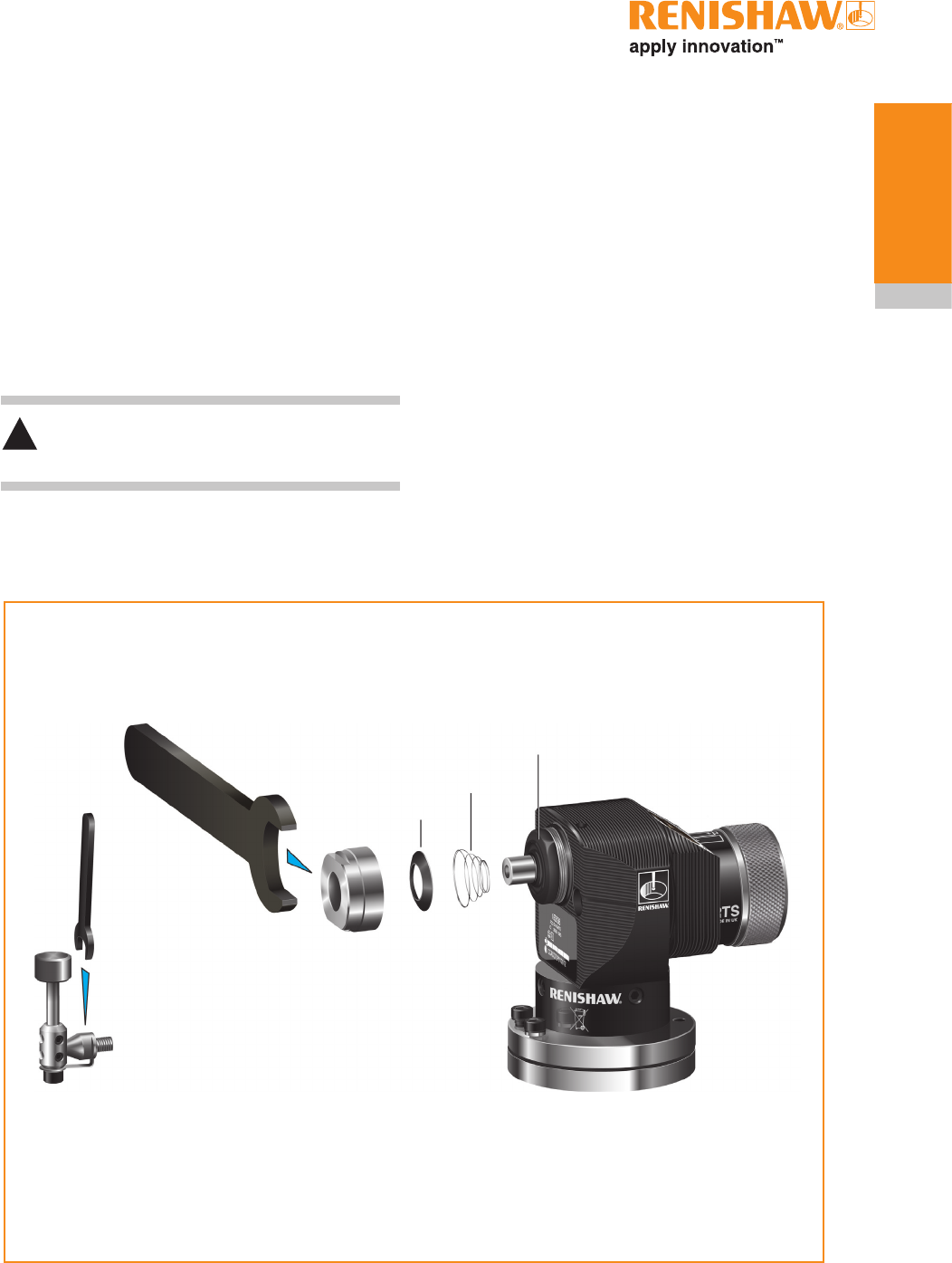
using the 5 mm AF spanner.
2. Use a 24 mm or 15/16 in spanner to remove
the probe’s front cover. This will expose
the metal eyelid seal, spring and the inner
diaphragm seal. Remove the metal eyelid
and spring.
CAUTION:
Loose components may fall out.
Front cover
Inner diaphragm seal
Metal eyelid seal
Spring
Spanner
24 mm or 15/16 in
3 Nm
(1.47 lbf.ft)
Stylus and break stem assembly
Spanner
5 mm AF
2.6 Nm
(1.92 lbf.ft)
!
3. Wash inside the probe, using clean coolant.
(DO NOT use sharp objects to clean out
debris).
4. Inspect the diaphragm seal for signs of
piercing or damage. In the event of damage,
return the probe to your supplier for repair, as
coolant entering the probe mechanism could
cause the probe to fail.
5. Refit the spring and metal eyelid (the spring’s
largest diameter is against the metal eyelid).
6. Refit the remaining components.

RTS installation guide
5.6
Maintenance
This page left intentionally blank

Symptom Cause Action
Probe fails to power up
(no LEDs illuminated or
fails to indicate current
probe settings).
Dead batteries. Change batteries.
Wrong batteries. Change batteries.
Batteries inserted incorrectly. Check battery insertion/polarity.
Probe fails to switch on. Dead batteries. Change batteries.
Batteries inserted incorrectly. Check battery insertion.
Probe out of range. Check position of RMI/RMI-Q, see
operating envelope.
No RMI/RMI-Q "start/stop"
signal.
Check RMI/RMI-Q for green start
LED.
RTS in hibernation mode. Ensure probe is in range and wait
up to 30 seconds, then resend
switch-on signal.
Check position of RMI/RMI-Q, see
operating envelope.
Machine stops
unexpectedly during a
probing cycle.
Radio link failure/RTS out of
range.
Check interface/receiver and
remove obstruction.
RMI receiver/machine fault. Refer to receiver/machine user’s
guide.
Dead batteries. Change batteries.
Probe unable to find target
surface.
Check that part is correctly
positioned and that stylus has not
broken.
False probe trigger. Enable enhanced trigger filter.
Spindle crashes into
probe
Tool length offset incorrect. Review offsets.
In cases where there is more
than one probe on a machine,
incorrect probe activated.
Review interface wiring or part
program.
6.1
Fault finding

Symptom Cause Action
Poor probe repeatability
and/or accuracy.
Debris on part or stylus. Clean part and stylus.
Loose probe mounting on
machine bed or loose stylus.
Check and tighten as appropriate.
Excessive machine vibration. Enable enhanced trigger filter.
Eliminate vibrations.
Environmental or physical
change caused an error in
calibrated offset.
Review probing software.
Calibration and probing speeds
not the same.
Review probing software.
Measurement occurs as stylus
leaves surface.
Review probing software.
Measurement occurs within
the machine’s acceleration and
deceleration zone.
Review probing software and
probe filter settings.
Probing speed too high. Perform simple repeatability trials
at various speeds.
Temperature variation causes
machine and workpiece
movement.
Minimise temperature changes.
Machine tool faulty. Perform health checks on
machine tool.
RTS status LEDs do
not correspond to RMI
status LEDs.
Radio link failure – RTS out of
RMI/RMI-Q range.
Check position of RMI/RMI-Q, see
operating envelope.
RTS has been enclosed/shielded
by metal.
Remove from obstruction.
RTS and RMI/RMI-Q are not
partnered.
Partner RTS and RMI/RMI-Q.
RTS installation guide
6.2
Fault finding

Symptom Cause Action
RMI/RMI-Q error LED lit
during probing cycle.
Probe not switched on or probe
timed out.
Change setting. Review turn off
method.
Probe out of range. Check position of RMI/RMI-Q, see
operating envelope.
RMI/RMI-Q low battery
LED lit.
Low batteries. Change batteries soon.
Reduced range. Local radio interference. Identify and remove.
Probe fails to switch off. Incorrect switch-off method
configured.
Check configuration and alter as
required.
No RMI/RMI-Q 'start/stop' signal. Check RMI/RMI-Q for green start
LED.
Probe in timeout mode and
placed in tool magazine and is
being triggered by movement.
Use shorter timeout setting or use
different switch-off mode.
Probe goes into Trigger
Logic™ configuration
mode and cannot be
reset.
Probe trigger function is
damaged.
Return to Renishaw.
6.3
Fault finding

RTS installation guide
6.4
Fault finding
This page left intentionally blank

7.1
Parts list
Type Part number Description
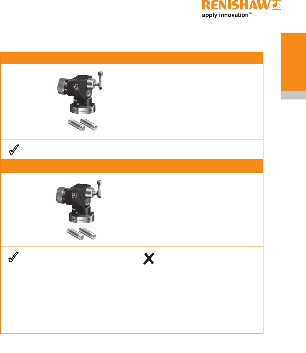
RTS A-5646-0001 RTS probe with disc stylus, AA alkaline batteries, tool kit and
quick-start guide. Set to trigger filter off.
Disc stylus A-2008-0382 Disc stylus (tungsten carbide, 75 Rockwell C)
Ø12.7 mm (Ø0.5 in).
Square stylus A-2008-0384 Square tip stylus (ceramic tip, 75 Rockwell C)
19.05 mm x 19.05 mm (0.75 in x 0.75 in).
Break stem kit A-5003-5171 Stylus protection kit comprising: break stem (x1),
captive link (x1), support bar (x1), M4 screw (x2),
M4 grub screw (x3), hexagon keys: 2.0 mm (x1), 3.0 mm (x1)
and spanner 5.0 mm (x1).
Stylus holder kit A-2008-0389 Stylus holder kit comprising stylus holder and screws.
AA battery P-BT03-0005 AA Alkaline batteries (pack of two).
AA battery P-BT03-0008 AA Lithium Thionyl Chloride (LTC) batteries (pack of two).
Battery cap A-5401-0301 RTS battery cap assembly.
Seal A-4038-0301 Battery housing seal.
Tool kit A-5401-0300 Tool kit comprising : break stem (x1), captive link (x2),
support bar (x1), M4 screw (x2), M4 grub screw (x3),
Spirol pin (x2), hexagon keys: 2.0 mm (x1), 2.5 mm (x1),
3.0 mm (x1), 4.0 mm (x1) and spanner 5.0 mm (x1).
RMI A-4113-0050 RMI – side exit – with 15 m (49.2 ft) cable, tool kit and user's
guide.
RMI-Q A-5687-0050 RMI-Q – side exit – with 15 m (49.2 ft) cable, tool kit and
user’s guide.
Mounting bracket A-2033-0830 Mounting bracket with fixing screws, washers and nuts.
Publications. These can be downloaded from our web site at www.renishaw.com
RTS A-5646-8500 Quick-start guide: for rapid set-up of the RTS probe, includes
CD with installation guides.
Styli H-1000-3200 Technical specification: Styli and accessories.
Software features H-2000-2289 Data sheet: Probe software for machine tools – illustrated
features.
Software list H-2000-2298 Data sheet: Probe software for machine tools – list of
programs.
RMI H-2000-5220 Installation and user's guide: RMI – radio machine interface.
RMI-Q H-5687-8500 Quick-start guide: for rapid set-up of the RMI-Q, includes CD
with installation guide.

RTS installation guide
7.2
Parts list
This page left intentionally blank

Renishaw plc
New Mills, Wotton-under-Edge,
Gloucestershire, GL12 8JR
United Kingdom
T +44 (0)1453 524524
F +44 (0)1453 524901
E uk@renishaw.com
www.renishaw.com
For worldwide contact details,
please visit our main website at
www.renishaw.com/contact
*H-5646-8504-01*
© 2011 Renishaw plc Issued BETA SITE ONLY VERSION Part no. H-5646-8504-01-A