Repeater Technologies OC80002 Distributed Antenna Systems User Manual Manual
Repeater Technologies Inc Distributed Antenna Systems Manual
Contents
- 1. users manual
- 2. Revised manual page to include rf exposure statement
Revised manual page to include rf exposure statement
2-2
The RF cable must have an SMA male connector for the connection to the Remote Transceiver. If the
antenna has a different RF connector, say, N or TNC, an RF adapter must be used. Plug in the transmit
(downlink) fiberoptic cable connector into the OPTICAL IN on the Remote Transceiver and the receive
(uplink) fiberoptic cable connector into the OPTICAL OUT (Green) on the Remote Transceiver.
From the initial network design, the output power required from each Remote Transceiver should be
known. This can be preset before power is turned on by turning the Output Power adjustments on each
Remote Transceiver. From the maximum output power rating for each Remote Transceiver, the power can
be reduced in 2 dB using the indented potentiometer.
Turn the power on to the Remote Transceivers and on the Hub Shelf. Proper operation of the optical
system is indicated by a green Node Function LED on each of the Hub Transceiver Plug-Ins that is
connected to an active Remote Transceiver. All other alarm indicators should be OFF. A yellow LED at
the plug-in or at the Remote Transceiver indicates that the optical loss in that path is > 4 dB and is,
therefore, out of the range of the guaranteed specification.
Before connecting the Hub Shelf to the BTS or Repeater, check that the RF transmit power from the
source (BTS or repeater) is within the safe operating range of the OFFICECELL and that it is at the level
required for proper noise and distortion performance according to the network design (see Table 1).
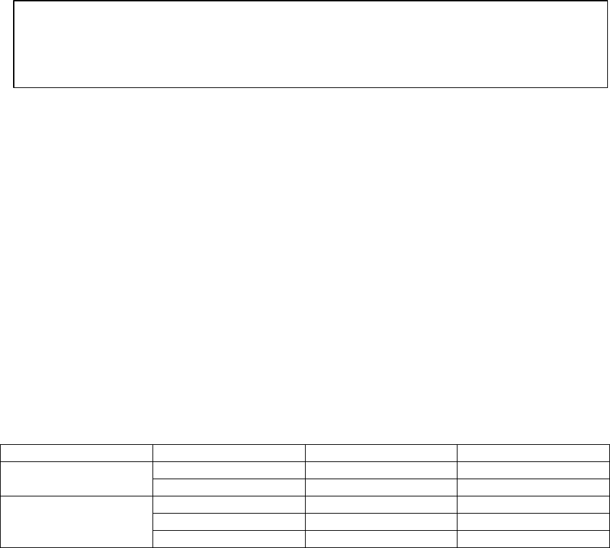
Table 1. Transmit (Downlink) Input RF Levels/carrier
GSM (05.05) TDMA (IS-136) CDMA (IS-95)
+12 dBm, 1 carrier +11 dBm, 2 carriers +3 dBm, 1 carrier800MHz/900MHz
Power P1 (2 dB gain) +4 dBm, 2 carriers +8 dBm, 4 carriers 0 dBm, 2 carriers
+8 dBm, 1 carrier +3 dBm, 4 carriers -2 dBm, 1 carrier
-1 dBm, 2 carriers 0 dBm, 8 carriers -5 dBm, 2 carriers
GSM1800/1900MHz,
800MHz/GSM900
Power P2 (14 dB gain) -4 dBm, 4 carriers -3 dBm, 10 carriers -8 dBm, 4 carriers
Connect the RF cables between the BTS or repeater and the Hub Shelf. The Remote Transceivers and the
plug-ins have been calibrated at the factory and the optical loss compensation in each Remote Power
Supply and plug-in automatically equalizes the gain in each link so that the specified link gain is always
met. The system is now operational and no further adjustment is necessary.
IMPORTANT NOTE! to comply with FCC RF Exposure compliance requirements, the following
antenna installation and device operating configurations must be satisfied:
Any antenna connected to this device must result in an ERP < 1.5W(800 and 900MHz) or < 3.0W
(1800MHz and 1900MHz)! and must be mounted such that there is at least 20centimeter spacing
from the antenna structure and a human body.