Repeater Technologies OC80002 Distributed Antenna Systems User Manual users manual
Repeater Technologies Inc Distributed Antenna Systems users manual
Contents
- 1. users manual
- 2. Revised manual page to include rf exposure statement
users manual

OfficeCell Manual, Rev. E3
Operating Manual
OfficeCell
Distributed Antenna System
ii

iii
Table of Contents
1 LINK DESCRIPTION........................................................................................................................................1-1
1.1 CAUTIONS AND WARNINGS...........................................................................................................................1-1
1.2 GENERAL DESCRIPTION.................................................................................................................................1-1
1.2.1 Basic Principles ..................................................................................................................................1-2
1.2.2 Functional Description .......................................................................................................................1-3
1.3 SPECIFICATIONS............................................................................................................................................1-7
2 INSTALLATION ...............................................................................................................................................2-1
2.1 GENERAL PROCEDURE...................................................................................................................................2-1
2.2 INSTALL FIBEROPTIC CABLES ........................................................................................................................2-4
2.2.1 Minimizing Optical Reflections ..........................................................................................................2-4
2.2.2 Cleaning Optical Connectors..............................................................................................................2-5
2.3 SYSTEM ALARMS ..........................................................................................................................................2-6
2.4 HUB SHELF AND REMOTE POWER SUPPLY BATTERY CHARGE MONITORING AND BATTERY REPLACEMENT....2-6
2.4.1 Replacing the Hub Shelf Battery.........................................................................................................2-6
2.4.2 Replacing the Remote Power Supply Battery .....................................................................................2-7
2.5 INSTALLATION CHECKLIST............................................................................................................................2-7
2.5.1 Inspect Received Items........................................................................................................................2-7
2.5.2 Recommended Tools............................................................................................................................2-8
2.6 INSTALLING THE HUB SHELF..........................................................................................................................2-8
2.7 INSTALLING THE REMOTE TRANSCEIVERS......................................................................................................2-9
3 MONITORING AND TROUBLESHOOTING...............................................................................................3-1
3.1 FIELD SUPPORT NUMBERS .............................................................................................................................3-1
3.2 TROUBLESHOOTING TIPS...............................................................................................................................3-2
iv

1-1
1 Link Description
1.1 Cautions and Warnings
Throughout this manual, these terms appear which highlight the care that should be exercised to ensure
personal safety and proper operation of the equipment.
WARNING: Warning statements identify conditions or practices
that could result in injury or loss of life.
CAUTION: Caution statements identify conditions or practices
that could result in damage to this product or other property.
NOTE: this equipment has been tested and found to comply with the limits for a Class B digital
device, pursuant to Part 15 of the FCC rules. These limits are designed to provide reasonable
protection against harmful interference in a residential installation. This equipment generates, uses
and can radiate radio frequency energy and if not installed and used in accordance with the
instructions, may cause harmful interference to radio communications. However, there is no
guarantee that interference will not aoccur in a particular installation. If this equipment does cause
harmful interference to radio or television reception, which can be determined by turning the
equipment off and on, the user is encouraged to try to correct the interference by one or more of the
following measures:
- Reorient or relocate the receiving antenna
- Increase the separation between the equipment and receiver
- Connect the equipment into an outlet on a circuit different from that to which the receiver is
connected
- Consult the dealer or an experienced radio/TV technician for help.
CAUTION: any modifications to this device not expressly
authorized by Repeater Technologies, Inc. could void the user’s
authority to operate this device.
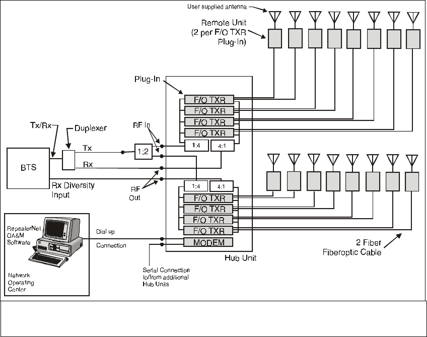
1.2 General Description
The OFFICECELL Fiberoptic Distributed Antenna System provides extended coverage of cellular and PCS
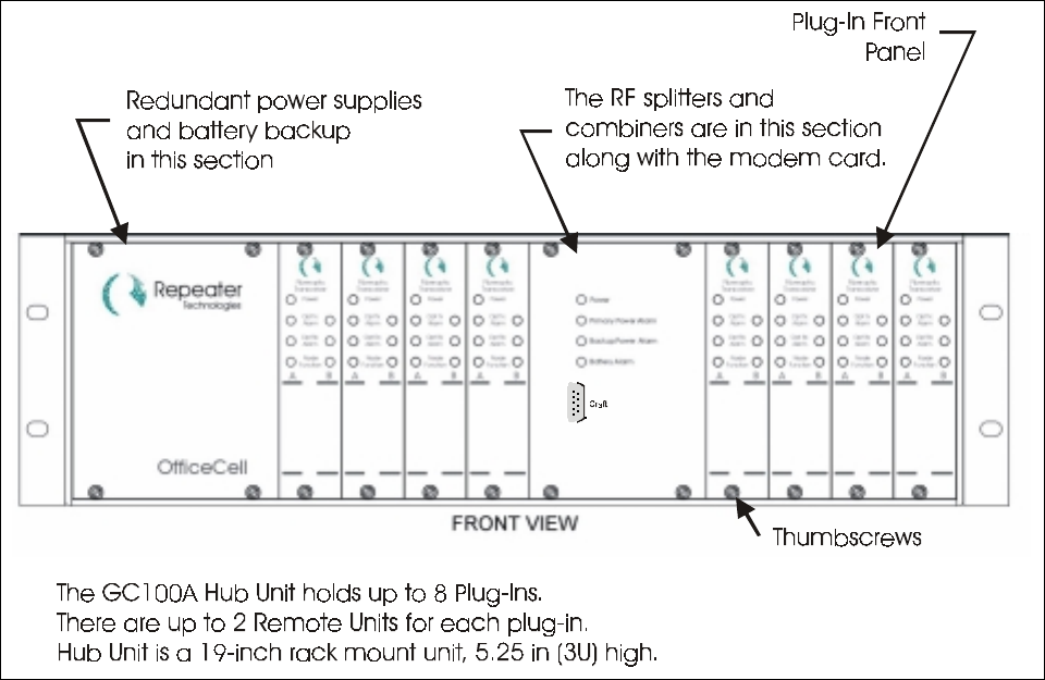
networks throughout buildings and campus environments. The Hub Shelf is the HUB SHELF which is a 3U
(5.25 inch) high, 19 inch wide rack-mounted chassis. The HUB SHELF holds up to 8 HUB TRANSCEIVER
Plug-Ins. The Hub Shelf is located in a communications equipment room in the building and is connected to
the cellular/PCS base station or repeater via hardline connection. The Hub Shelf may also be connected to
the radios of a wireless PBX. Each Hub Shelf is configured with up to eight HUB TRANSCEIVER plug-in
cards. Each card is connected to up to two Remote Transceivers. The REMOTE TRANSCEIVER Units are
1-2
distributed throughout the building as necessary to provide coverage. The Remote Transceivers are mounted,
generally, above the suspended ceiling but may be mounted near the ceiling inside the room if need be. The
aesthetic and low-profile design of the Remote Power Supply makes it relatively unobtrusive. The plastic
cover may even be removed and/or painted to match the décor. Each REMOTE TRANSCEIVER is
connected to Hub Shelf via two singlemode optical fibers. Each REMOTE TRANSCEIVER has one RF port
which is connected to a user-supplied indoor coverage antenna. This port may also be routed through an N-
way RF splitter to provide coverage from a number N antennas for the one Remote Transceiver. This reduces
the output power and sensitivity at that Remote Transceiver but, in some cases, this could be the most cost-
effective way to provide unifirm coverage. The REMOTE TRANSCEIVER is powered by +12 to 24 VDC
which can be supplied by the customer or by the Remote Power Supply. This is a universal AC power supply
with battery backup and is installed with the REMOTE TRANSCEIVER on a wall mounting bracket supplied
with the unit. If DC power is supplied by the customer, it can be distributed from a power supply at the Hub
location using the conductor pairs in a composite fiber/conductor cable. The DC connector utilized at the
Remote Transceiver can accommodate up to 14 AWG wire.
The OFFICECELL design is very versatile but certain options are available that target specific signal types
and applications. In addition to the single band versions, there is an 800 MHz/1900 MHz dual band and a
GSM900/GSM1800 dual band option. There is also a high power 800MHz and GSM900 option. This option
provides a +22 dBm single carrier output for GSM900 or, for 800 MHz, 10 carriers of IS-136 at +10
dBm/carrier or +12 dBm for single carrier CDMA. The system performance is specified for 4 dB optical
loss.
OFFICECELL installation and setup is very simple. First, standard telcom grade singlemode fiberoptic cable
that is most suitable for the site is installed. The cable installer can terminate the cable on site easily with the
OptoClip optical connectors. The Plug-Ins and Remote Transceivers of a given type are completely
interchangeable. The OptoClip plugs directly into the Remote Transceiver at one end. The other end plugs
into an optical patch panel or directly into the Hub Shelf via an OptoClip-to-SC/UPC adapter. If the patch
panel is used, OptoClip-to-SC/UPC jumpers must be used to connect the HUB SHELF to the patch panel.
Built-in optical loss compensation automatically equalizes the gain in both the transmit and receive paths so
the transmit RF power is known for a given input RF power and the receive path sensitivity is optimized. The
only adjustment available is a manual setting for the static transmit power at the Remote Transceiver which
may be used to optimize coverage, if necessary. This is a one time adjustment during set up.
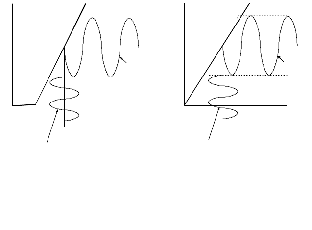
1.2.1 Basic Principles
The OFFICECELL
operation is based on an
analog RF fiberoptic link.
The principles are
illustrated in Figure 1.
Input RF signals are
converted to light by
direct intensity
modulation of a
semiconductor laser. This
modulated light is
transmitted over optical
fiber and detected by a
semiconductor PIN
photodiode. The
photodiode converts
optical power to
electrical current. This
current is AC coupled
Figure 0. Laser diode and photodiode characteristics illustrating the
o
p
eration of an analo
g
fibero
p
tic link.
I
bias
I (mA) I (mA)
P (mW)
out
I
th
RF
Input
RF
Output (ac coupled
to remove dc component)
Optical
Output
Opti ca
l
Input
P (mW)
in
LASER DIODE
CHARACTERISTIC PHOTODIODE
CHARACTERISTIC
1-3
and passed through a load to recover the RF signal.
The basic RF loss in this link is determined by the inefficiencies of the conversions of RF to optical and
back. The fiber also contributes an RF loss equal to twice the optical loss. This is because the photodiode
converts optical power to electrical current and RF power is proportional to the square of the current. So,
for 1 km of fiber with a loss of 0.4 dB/km (this is typical at 1310 nm wavelength) the optical loss is 0.4 dB
and the contribution to the RF loss is 0.8 dB. In a real installation, two optical connectors will add
approximately 0.5 dB of optical loss.
The laser and, to a much lesser degree, the photodiode, add noise and distortion to the RF signal. This RF
performance is characterized just as any RF link in terms of dB loss, noise figure, third order intercept, etc.
The fiber path itself can contribute noise and distortion. In the OFFICECELL, the laser used is a Fabry-Perot
(FP) laser instead of a Distributed Feedback (DFB). The DFB has a single spectral component. The FP laser
has multiple spectral components which can contribute noise and distortion for longer fiber runs. For the
distances used in the OFFICECELL, this effect is not significant. Also, optical backscattering back into the
laser from less than perfect connections can cause additional noise and distortion. The FP lasers used in the
OFFICECELL are much less sensitive to this than are DFB lasers. DFB lasers are also considerably more
expensive. However, if optical reflections are severe enough from a bad connection, the resulting optical
reflection may cause performance degradation. To minimize this, SC/UPC optical connectors with a return
loss > 50 dB are used at the Hub Shelf and OptoClip connectors with a return loss of > 60 dB are used at the
Remote Transceiver. Following standard practices in cleaning of the removable optical connectors (see
procedure outlined below) will keep the connections in spec and will avoid the problems of performance
degradation.
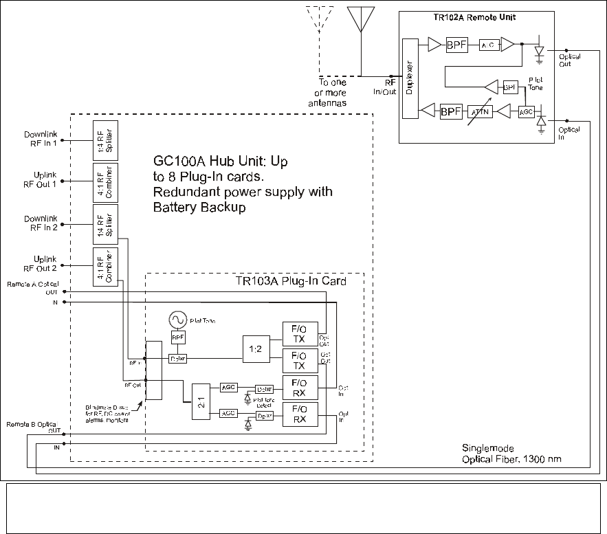
1.2.2 Functional Description
The OFFICECELL Fiberoptic Antenna System connects to the mobile coverage RF ports of a repeater or
Figure 2. System Block Diagram
1-4
base station as an extended coverage antenna. The Hub Shelf mounts in a standard 19 inch rack close to the
repeater or base station transmit and receive RF ports. These RF connections are made via the RF connectors
on the rear panel. Inside the chassis, the transmit signal is split and routed to the Hub Transceiver Plug-Ins.
Each plug-in is a fiberoptic transceiver. The Hub Shelf holds up to eight plug-ins. Each plug-in interfaces
with up to two Remote Transceivers by way of fiberoptic connections on the Hub Shelf rear panel.
The HUB TRANSCEIVER Plug-Ins are connected to the Remote Transceivers via singlemode fiber at 1310
nm wavelength. Separate fibers are needed for the transmit and receive signals. SC/UPC optical connectors
(SC/PC snap-in connectors with an “ultra-polish”) are used at the Hub Shelf. These connectors are used
because they are compatible with the optical blindmate connectors used on the HUB TRANSCEIVER Plug-
Ins. The bulkhead connectors are polished to a return loss of > 50 dB.
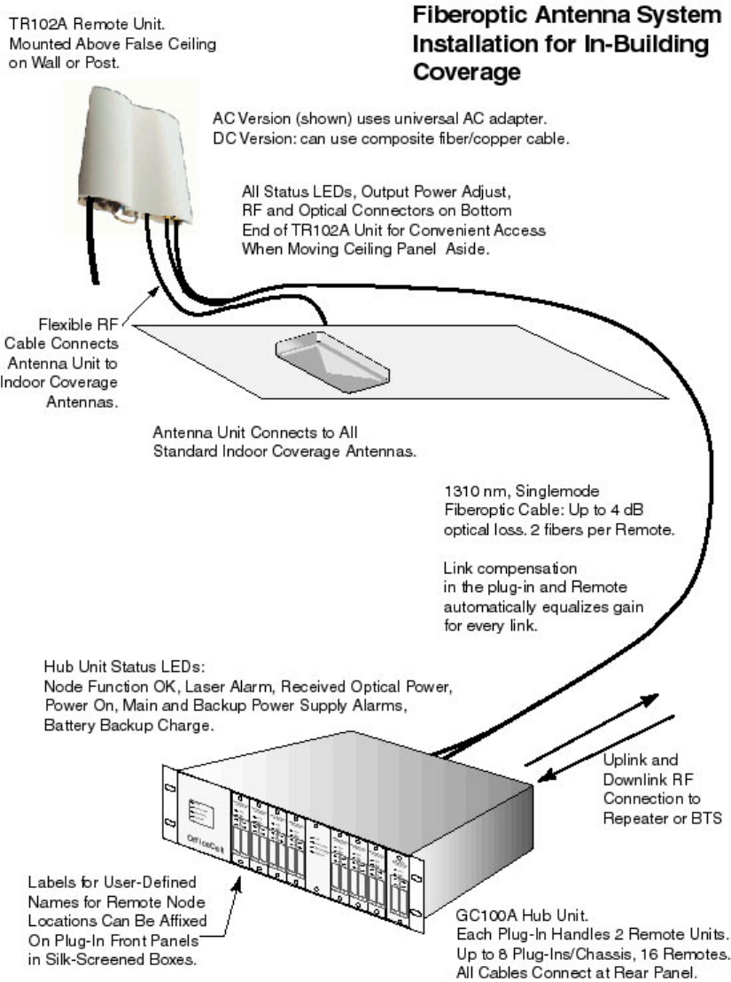
The Remote Transceiver is a fiberoptic transceiver that connects to an external indoor coverage antenna.
Depending on coverage and cost requirements, an RF splitter may be used to connect the Remote Transceiver
to two or more antennas. The Remote Transceiver uses field-installable OptoClip II optical connectors. The
Remote Transceiver optical output is the green connector. The REMOTE TRANSCEIVER units are generally
mounted above the false ceiling on a bulkhead or post. Each REMOTE TRANSCEIVER is connected to an
indoor coverage antenna by way of a customer-supplied flexible RF cable. Some indoor antennas are
available with flexible RF cable pigtails and an SMA connector termination. These units are distributed
throughout the building or campus as necessary to get full coverage. After installation, the transmit power
from each Antenna Unit may be adjusted manually by way of an potentiometer on the unit. This is
Figure 3. OfficeCell RF Path Block Diagram.
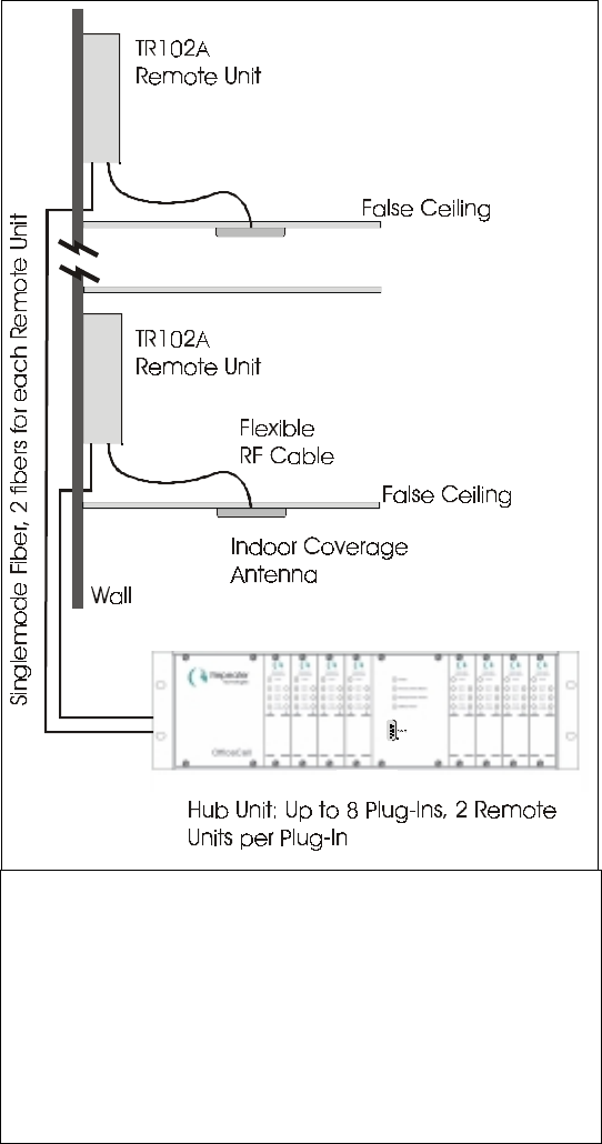
1-5
Figure 4. The Remote Transceivers are normally mounted
above the false ceiling but may be mounted in the room.
Each Remote Power Supply is connected to the Hub Shelf
via 2 singlemode fibers. The Remote Power Supply is
connected to a user-supplied antenna via flexible RF cable.
The Remote Transceivers may be powered using the
optional universal Remote Power Supply with battery
backup, or using a central power supply that distributes DC
power along with the fiber over a composite fiber/conductor
potentiometer indented in 2 dB steps. This is a one time adjustment. For dual band units, there is a separate
adjustment for each band.
Several versions of the REMOTE TRANSCEIVER are available that are optimized for specific formats such
as DAMPS, GSM900, GSM1800, etc. Dual band versions are available; one providing simultaneous
coverage for GSM900 and GSM1800 and one for PCS1900 and 800 MHz. In these versions, a single RF port
feeds a dual band antenna.
The block diagram of the OFFICECELL Fiberoptic Antenna System is shown in Figures 2 and 3. The input
transmit RF signal is split eight ways in the Hub Shelf. Each of these signals is routed to a Hub Transceiver
Plug-In where it is split in two and each path modulates the optical output of a solid state laser diode. This
optical output is routed through a
singlemode optical fiber to one Remote
Transceiver. The photodiode in the
REMOTE TRANSCEIVER detects this
optical signal and outputs a proportional
electrical current. This current is ac
coupled and passed through a load to
recover the RF signal. The RF signal is
amplified, filtered and output to the
antenna. The output RF signal path
includes a variable attenuator to adjust
the output level for optimum coverage.
The RF subcarrier is detected at the
photodiode output. This level is used by
the transmit AGC to set the downlink
gain. The subcarrier is also amplified and
inserted into the uplink path. This signal
is detected at the Hub Shelf Plug-In for
the uplink AGC and Node Function
Alarm. A failure of any amplifier in the
downlink path in the Remote Transceiver,
shuts off the subcarrier in the return path
which, in turn, triggers the Node Function
Alarm at the Hub.
The receive or uplink RF signal from the
antenna is filtered and amplified then
routed to the Remote Transceiver laser.
A fast ALC is included in this path which
prevents RF overdrive damage to the
laser while recovering fast enough to
minimize blocking for TDMA and GSM
signals. The laser output in the Remote
Transceiver is then modulated by the
receive RF signal and is transmitted
through another singlemode optical fiber
back to the Hub Shelf Plug-In. Each of the
two photodiodes in the Hub Transceiver
Plug-In recovers the RF signals from
each of two Remote Transceivers. The
pilot tone on each signal is split off and
detected. This is used for the Node
Function alarm. This LED is normally
green and turns red if the pilot tone is not
detected. This alarm also appears at the
1-6
Hub Shelf rear panel DB37 connector as a TTL level critical alarm. It would also be reported to the NOC or
service technician by the modem card depending on how the user configured the system alarms.
The receive RF signal from each photodiode is combined in the HUB TRANSCEIVER Plug-In. These
combined outputs are combined again in the and output to the rear panel RF uplink connectors. The Hub Shelf
is divided into two halves. The RF signals from each half are combined and routed to separate rear panel N
connectors. The combined uplink signals from one half can be routed to the BTS main receive port while the
other RF output is routed to the BTS receive diversity port. This method provides an overall 3 dB system
sensitivity improvement compared to routing all of the uplink signals into one receive port (see Figure 2).
Alternatively, both outputs may be combined and routed to a single BTS receive port.
1-7
1.3 Specifications
Description
This specification defines the uplink and downlink performance of the OfficeCell Fiberoptic Antenna System.
The terminal equipment consists of the Remote Transceiver and the Hub Transceiver Plug-In. The latter is
installed in the Hub Shelf. This system meets and exceeds the requirements for GSM900, GSM1800 and
GSM1900 Class M3 micro-BTS as well as IS-136 TDMA and IS-95 CDMA for wireless PBX, in-building
and campus coverage applications.
There are four frequency options for the OfficeCell: 850 MHz (AMPS), GSM900, GSM1800 and PCS1900.
There are two downlink output power options: the P1 power option meets GSM 900 micro-BTS M3
requirements and is available for the 850MHz and 900MHz versions only. The P2 power option meets
micro-BTS M3 requirements for 1800MHz and 1900MHz. For 850MHz and 900MHz, the High Power meets
GSM micro-BTS power class M1 requirements and IS-136 in-building requirements for +20 dBm composite
power. All of these system standards specifications are met for optical loss of up to 4 dB.
RF Parameters (up to 4 dB optical loss)
Uplink
Frequency Range 850 MHz 824 - 849 MHz
GSM900 890 - 915 MHz
GSM1800 1710 - 1785 MHz
PCS1900 1850 - 1910 MHz
Amplitude Flatness
824 – 849, 890 - 915 MHz; Full band ± 1.5 dB
(Any 15 MHz band) ± 1.0 dB
1710 – 1785, 1850 - 1910 MHz; Full band ± 2.5 dB
(Any 15 MHz band) ± 1.0 dB
Noise Figure ≤ 13 dB
Low Noise Option ≤ 7 dB
Input Third Order Intercept (IIP3), 2 carriers, -43 dBm/carrier ≥ -15 dBm
Low Noise Option ≥ -25 dBm
Link Gain (with external 20 dB attenuator; 30 dB attenuator with Low Noise Option)
824 - 915 MHz 4 ± 1 dB
1710 - 1910 MHz 4 ± 1 dB
Uplink Input ALC
Input RF Threshold - 25 dBm
Low Noise Option -35 dBm
Range 30 dB
Response Time < 5 µsec w/o ringing
Gain Stability ± 1 dB
Input/Output Impedance 50 Ω
Input/Output VSWR ≤ 2 : 1
Downlink
Frequency Range 850 MHz 869 - 894 MHz
GSM900 935 - 960 MHz
GSM1800 1805 - 1880 MHz
PCS1900 1930 - 1990 MHz
Amplitude Flatness

1-8
869 – 894, 935 - 960 MHz; Full band ± 2.5 dB
(any 15 MHz band) ± 1.0 dB
1805 – 1880, 1930 - 1990 MHz; Full band ± 2.5 dB
(any 15 MHz band) ± 1.0 dB
Output Noise ≤ -92 dBm/Hz
Output Third Order Intermodulation Product
(Interfering CW carrier 30 dB below main carrier,
for single carrier at max output power) ≤ -38 dBm
2 Equilevel Carriers at +17 dBm/carrier ≤ -42 dBc
Output Power, Maximum (dBm)
Std Single Carrier 2 Equilevel Carriers
(Power/Carrier)
GSM +14 +5
IS-136 +12 +9
P1
CDMA +4 +1
GSM +22 +13
IS-136 +20 +17
P2
CDMA +12 +9
Output Power Range ≥ 12 dB user adjustable (in 2 dB
increments at TR102 Remote
Transceiver)
Input Power Threshold for Input Power Protect 8.5 to 11.5 dBm
Attenuation Step for Input Power Protect 10 dB
Gain at Maximum Output Power (output attenuator set at min)
Output Power Option P1 2 ± 1 dB
Output Power Option P2 14 ± 1 dB
Gain Stability ± 1 dB
Input/Output Impedance 50 Ω
Input/Output VSWR ≤ 2 : 1
General
Loop back Carrier Frequency 99 MHz ± 10 MHz
Optical Parameters
Wavelength 1310 ± 20 nm
Output Power
Remote Transceiver 1.8 mW
Hub Transceiver Plug-In 1.8 mW
Optical Connector
Hub Shelf SC/UPC, > 50 dB return loss
Remote Transceiver Optoclip II®, > 55 dB return loss
Fiber Singlemode
Absolute Maximum Ratings
RF Input Power
Uplink +5 dBm
Low Noise Option -5 dBm
Downlink +26 dBm total
Photodiode Input Optical Power +2.3 mW
1-9
Electrical
Remote Transceiver +12 V to +24 V, 12 W (single
band), 20 W (dual band)
Remote Power Supply 100 to 240 VAC, 47 – 63 Hz
Hub Transceiver Plug-In 6 W
Hub Shelf 100 - 240 VAC, 47 - 63 Hz
1-10
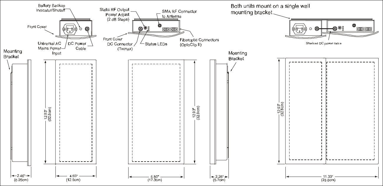
Mechanical
Remote Transceiver See outline drawing below
1-11
Hub Shelf Plug-In (HUB TRANSCEIVER) Plug-in card with 5.06” H x 1.2” W front
panel for HUB SHELF Chassis.
Hub Shelf (HUB SHELF) 19”, 3U (5.25”) H, 15.75” D rack mount
1-12

1-13
Alarms and Monitors
Remote Transceiver
Description
Power On (Green LED)
Laser Optical Power Low Alarm (active if laser output < 90% of factory set point:
Red Front panel LED)
Received Optical Power Low Warning (active if optical loss > 4.2 dB: Yellow
front panel LED)
Transmit Amplifier Failure Alarm (active if any amplifier in transmit path fails as
detected by bias current: Red LED. Also causes shutoff of subcarrier in uplink path
which triggers Node Function Alarm at plug-in.)
Hub Transceiver Plug-In Node Function (loopback carrier detect:
Front panel LED; normally Green, Red if RF
subcarrier level drops more than 10 dB)
Received Optical Power Low Warning
(active if optical loss > 4.2 dB: Yellow front
panel LED, normally OFF)
Laser Optical Power Low Alarm (active if
laser optical output power drops 10%): Red
Front panel LED, normally OFF)
Hub Shelf
LEDs Power On (Green, Normally ON)
Main Power Alarm (Red Front panel LED;
normally OFF)
Backup Power Alarm (Red Front panel LED;
normally OFF)
Battery Alarm (Yellow front panel LED,
active if battery backup charge is low;
normally OFF)
Alarms, Rear Panel DB-37 (See Table) Critical Alarms: these include all Node
Function Alarms and the Main and Backup
Power Supply Alarms.
Summary Contact Closure Alarm: active if
any alarm is active in chassis or plug-ins.
RepeaterNet Any critical alarm prompts the system to dial up
Remote Power Supply NOC. This is configured at
installation with a laptop computer via the front panel
Craft interface. Dial up connection is made with RJ-11
interface on rear panel. The system may also be polled
through dial up connection to get status of all alarms
and warnings.
Craft Interface (Front Panel) Used to set up RepeaterNet interface.
Includes setting telephone number of master Hub Shelf
as well as the NOC or service pager. Also configures
Hub Shelf as master or slave. Master provides dial up

1-14
connection for itself and daisy-chained slave units.
Connection to slave units via RJ-45 jacks on rear.
DB-37 Pin Signal name Type Sense
1 1-A Node Function Alarm TTL Active Low
2 2-A Node Function Alarm TTL Active Low
3 3-A Node Function Alarm TTL Active Low
4 4-A Node Function Alarm TTL Active Low
5 5-A Node Function Alarm TTL Active Low
6 6-A Node Function Alarm TTL Active Low
7 7-A Node Function Alarm TTL Active Low
8 8-A Node Function Alarm TTL Active Low
9 Master P.S. Alarm TTL Active Low
10 Battery Alarm TTL Active Low
11 n.c.
12 n.c.
13 n.c.
14 n.c.
15 RTN
16 RTN
17 RTN
18 n.c.
19 n.c.
20 1-B Node Function Alarm TTL Active Low
21 2-B Node Function Alarm TTL Active Low
22 3-B Node Function Alarm TTL Active Low
23 4-B Node Function Alarm TTL Active Low
24 5-B Node Function Alarm TTL Active Low
25 6-B Node Function Alarm TTL Active Low
26 7-B Node Function Alarm TTL Active Low
27 8-B Node Function Alarm TTL Active Low
28 Back-up Power Supply Alarm TTL Active Low
29 n.c.
30 n.c.
21 n.c.
32 n.c.
33 n.c.
34 Summary Alarm N.C. Relay contact Connect to Common if O.K.
35 Summary Alarm Common Relay contact
36 Summary Alarm N.O. Relay contact Open if O.K.
37 n.c.

1-15
Environmental
Operating (ETSI EN 300 019-1-3)
Temperature Range +5 to +45ΕC
Rate of Temperature Change 0.5 °C/minute
Relative Humidity 5 to 85% RH, non-
condensing
Storage and Transportation
(ETSI 300 019-1-1 STORAGE, class 1.2)
(ETSI 300 019-1-2 TRANSPORTATION, class 2.3)
Temperature Range -40 to +70°C
Rate of Temperature Change 0.5°C/minute
Relative Humidity 10 to 100%
Vibration (Storage)
Vibration Test (Transportation)
Shock Test (Transportation)
Drop Test (Transportation)
Free Fall 30 - 40 0.4 1 on each face or 2 in normal attitude
Free fall 40 - 50 0.3 1 on each face or 2 in normal attitude
Regulatory UL, CSA, FCC Type
Acceptance for 800 MHz
and PCS versions.
CE Mark for GSM900 and
GSM1800 versions
PARAMETER FREQUENCY RANGE SEVERITY DURATION
(Hz) Vel; mm/s Accel; m/s2
Sinusoidal 5 – 62 5.0 3x5 sweep cycles
Sinusoidal 62 - 200 2 3x5 sweep cycles
PARAMETER FREQUENCY RANGE SEVERITY DURATION
(Hz) ASD: m2/s3Rolloff: dB/oct
Random 5 – 20 0.96 3 x 10 mins
Random 20 - 500 -3 3 x 10 mins
PARAMETER SHOCK SPECTRUM SEVERITY DURATION
(Hz) Accel: m/s2Number ms
Shock (m≤100kg) Half Sine 400 500 in each of
6 directions
or
1000 in
normal
attitude
6
PARAMETER MASS DROP HEIGHT NUMBER OF DROPS
(kg) (m)
Free Fall < 30 0.5 1 on each face or 2 in normal attitude
2-1
2 Installation
2.1 General Procedure
Before installing and, in fact, before even receiving the OfficeCell units, one can have the fiberoptic cables
installed and tested. The network planning has been completed which has determined the type, number and
location of Remote Transceivers needed for optimum coverage and capacity.
Install and check the fiberoptic cables first. Use any high quality, telcom grade singlemode fiberoptic cable.
The OptoClip II optical connectors are installed easily on site (contact Molex or Huber+Suhner for
installation kits and training for the OptoClip II). General practice is to terminate the fiberoptic cables at a
patch panel near the Hub Shelf. In this case, optical jumper cables will be needed to make the connection
between the patch panel and the Hub Shelf. These jumpers will be terminated with an OptoClip II connector
at one end and an SC/UPC at the other.
! Make sure to specify SC/UPC, not SC/PC. The standard SC/PC has an optical return loss < 27 dB
which can cause degradation of the system noise performance. SC/UPC specifies an “ultra” polish for
a return loss > 50 dB.
During this process, label each cable at each end to indicate whether it is transmit or receive and which
Remote Transceiver it is associated with. It is good practice to pull one or two additional fiber pairs to each
Remote Transceiver to allow for future expansion. Next, mount the Hub Shelf in the rack and connect the
fiberoptic cables. Do not connect the RF cables yet.
Mount the Remote Transceivers. Install the wall mounting brackets first. For mounting above a false ceiling,
orient the bracket so that the end of the Remote Transceiver with the connectors is pointing downwards.
When mounting inside the room, place the Remote Transceiver near the ceiling with the connectors pointing
upwards. This permits the most aesthetic routing of the cables. The plastic cover on the Remote Transceiver
may be removed by loosening the four screws on the back of the Unit. This permits the user to paint the cover
to match the room décor. If the REMOTE TRANSCEIVER is to be installed with the Remote Power Supply,
install the two mounting brackets next to each other linking them with the connector piece supplied with the
power supply mounting bracket. This will give the most aesthetic mounting with the proper spacing for an
easy DC power connection. Orient the bracket so that the threaded tab will be at the same end as the
connectors on the REMOTE TRANSCEIVER. Place the REMOTE TRANSCEIVER so that the rear panel
studs slide into the keyhole slots on the mounting bracket. Secure the unit by tightening the captive
thumbscrew on the REMOTE TRANSCEIVER to the threaded hole in the mounting bracket. The Remote
Power Supply installs in the same way. For the Remote Power Supply, if the red NO AC LED is on, press the
reset switch located next to the AC power connector which turns off the battery backup (when the mains is
not connected). For AC powered units, connect the AC power cords to the building mains according to local
building electrical codes. Connect DC power to the REMOTE TRANSCEIVER by connecting the shielded
cable with the twinax termination to the DC input connector on the REMOTE TRANSCEIVER.
Mount the indoor coverage antenna to the ceiling or wall as needed and connect it to the Remote Transceiver
with a flexible RF cable. The RF cable must have an SMA male connector for the connection to the Remote
Transceiver. If the antenna has a different RF connector, say, N or TNC, an RF adapter must be used. Plug in
the transmit (downlink) fiberoptic cable connector into the OPTICAL IN on the Remote Transceiver and the
receive (uplink) fiberoptic cable connector into the OPTICAL OUT (Green) on the Remote Transceiver.
From the initial network design, the output power required from each Remote Transceiver should be known.
This can be preset before power is turned on by turning the Output Power adjustments on each Remote

2-2
Transceiver. From the maximum output power rating for each Remote Transceiver, the power can be reduced
in 2 dB using the indented potentiometer.
Turn the power on to the Remote Transceivers and on the Hub Shelf. Proper operation of the optical system
is indicated by a green Node Function LED on each of the Hub Transceiver Plug-Ins that is connected to an
active Remote Transceiver. All other alarm indicators should be OFF. A yellow LED at the plug-in or at the
Remote Transceiver indicates that the optical loss in that path is > 4 dB and is, therefore, out of the range of
the guaranteed specification.
Before connecting the Hub Shelf to the BTS or Repeater, check that the RF transmit power from the source
(BTS or repeater) is within the safe operating range of the OFFICECELL and that it is at the level required
for proper noise and distortion performance according to the network design (see Table 1).
Table 1. Transmit (Downlink) Input RF Levels/carrier
GSM (05.05) TDMA (IS-136) CDMA (IS-95)
+12 dBm, 1 carrier +11 dBm, 2 carriers +3 dBm, 1 carrier800MHz/900MHz
Power P1 (2 dB gain) +4 dBm, 2 carriers +8 dBm, 4 carriers 0 dBm, 2 carriers
+8 dBm, 1 carrier +3 dBm, 4 carriers -2 dBm, 1 carrier
-1 dBm, 2 carriers 0 dBm, 8 carriers -5 dBm, 2 carriers
GSM1800/1900MHz,
800MHz/GSM900
Power P2 (14 dB gain) -4 dBm, 4 carriers -3 dBm, 10 carriers -8 dBm, 4 carriers
Connect the RF cables between the BTS or repeater and the Hub Shelf. The Remote Transceivers and the
plug-ins have been calibrated at the factory and the optical loss compensation in each Remote Power Supply
and plug-in automatically equalizes the gain in each link so that the specified link gain is always met. The
system is now operational and no further adjustment is necessary.
2-3
2-4
2.2 Install Fiberoptic Cables
Once the location for each of the Remote Transceivers has been determined, the fiberoptic cable can be
installed between the Hub Shelf and these locations. The cable length can be up to 5 km.
You need to know the following:
Optical Fiber Singlemode, 1310nm wavelength
Optical Loss Good quality fiber should have an optical loss of <
0.4 dB/km at 1310nm. There will be additional optical
loss due to connectors and splices but there should be
no more than about 0.5 dB loss through a connector
mating (optical connections are sexless) and less
through a splice.
Optical Connectors OptoClip II® connectors. These connectors are easily
installed on site. Contact Molex or Huber+Suhner for
installation kits and training. The Hub Shelf uses
SC/UPC connectors so an OptoClip-to-SC/UPC
adapter must be used. Alternatively, connect the Hub
Shelf to an OptoClip patch panel using optical jumpers
with an OptoClip termination at one end and an
SC/UPC termination at the other. IMPORTANT
NOTE: MAKE SURE TO USE AN SC/UPC
TERMINATION: THIS CONNECTOR IS AN
“ULTRA-POLISHED” CONNECTOR WITH AN
OPTICAL RETURN LOSS > 50 dB. A STANDARD
SC/PC TERMINATION HAS A HIGH RETURN
LOSS AND WILL DEGRADE LINK NOISE AND
LINEARITY PERFORMANCE.
Once the cable has been installed, the installer should check the quality of the optical path using an Optical
Time Domain Reflectometer (OTDR). This will check the optical path loss and the magnitude and location of
any reflections. The total return loss should be > 45 dB.
While checking the cables in this way, it is useful to label each cable near the connector as to which Remote
Transceiver it is for and whether it is for the transmit or receive path. Labelling the cable in this way permits
complete interconnection during installation with the system powered off. Otherwise, the Remote
Transceivers will have to be installed with the Hub Shelf power on with all fiberoptic cables connected to it.
This allows the installer to check which fiber is transmit by using an IR sensitive card (see Recommended
Tools).
2.2.1 Minimizing Optical Reflections
As discussed in the Functional Description, optical reflections can degrade the noise and linearity of a
fiberoptic link. In particular, reflections that reach the laser can be a problem. Keep all discrete reflections to
> 45 dB. For the Hub Shelf, the SC/UPC connectors are polished to a return loss >50 dB. At the Remote
Transceivers, the OptoClip connectors have a return loss of > 55 dB.
2-5
2.2.2 Cleaning Optical Connectors
Optical reflections from a discontinuity such as a poor connector interface appear on an RF spectrum
analyzer trace as stable variations in the noise floor amplitude that are periodic with RF frequency. If the
reflection is bad enough, it could impact the system performance. By far, the most common cause for a large
discrete reflection is a dirty optical connector. Remember that the optical aperture at the tip of the fiberoptic
connector is only 9 :m in diameter. A bit of dust or oil from a finger can easily interfere with or block this
light. Fortunately, it very easy to clean the connector. The procedures are indicated in the Figure. Be sure to
use the correct procedure for the given connector. When disconnected, cap the SC/UPC connector to keep it
clean and prevent scratching the tip of the ferrule. The OptoClip is “self-capping”.
Figure1. Keeping the tip of the optical connectors clean is a simple way to ensure optimum system
p
erformance.
2-6
2.3 System Alarms
The OfficeCell has three ways of indicating alarms.
1. LEDs: the Hub Shelf and the Remote Transceiver have status indicators for power on and alarm
conditions.
2. Hub Shelf Rear Panel DB37 Connector: The “critical” alarms are available here as TTL levels.
In addition, three pins provide a contact closure summary alarm (see Alarms in the
specifications).
3. Modem connection: The system status may be monitored locally with a computer through the
front panel Craft port. The main purpose of this port is to set the system initially. This includes
specifying which alarms are critical, setting the local system telephone number and specifying
the action to be taken when there is a critical alarm (dial up the NOC or a service technician’s
pager). With the RepeaterNet OA&M software, up to 5000 systems can be Remote Power
Supplyly monitored.
Using the alarms provided, the cause of a critical failure can be determined with high confidence. For
instance, if the Node Function alarm is associated with a Plug-In laser alarm, the Plug-In has failed and must
be replaced. If the Node Function alarm is associated with a Received Optical Power Low at the Plug-In,
either the Remote Transceiver laser has failed or the fiberoptic cable has been broken or damaged. The
service technician would come with a replacement Remote Transceiver. If, upon inspecting the Remote
Power Supply in question, the LEDs indicate no failure, the fiber path would have to be inspected. This
should be relatively easy to track down since damage would have to be associated with some other work
going on at the site or someone had deliberately disconnected the optical cable from the unit. Finally, a Node
Function alarm not associated with any other alarm at the Hub Shelf would indicate a failure of the Remote
Transceiver downlink amplifier chain. This would be confirmed by inspection of the Remote Power Supply
in question for that particular LED. The complete troubleshooting matrix is given at the end of this manual
and can be used to program the OA&M software to recommend the proper action to be taken.
2.4 Hub Shelf and Remote Power Supply Battery Charge Monitoring and
Battery Replacement
Both the Hub Shelf and the Remote Power Supply have a battery backup. While connected to mains power,
the battery is kept charged by a charging circuit. Once AC mains power is first connected, the charging circuit
waits 48 hours before starting the battery test circuit. This circuit checks to open circuit battery voltage every
ten seconds. Once the circuit detects the battery voltage drops below approximately 12 Volts, the BATT
LOW alarm is activated. At the beginning of life, the battery provides approximately 15 to 20 minutes of
system backup. At end of life, the backup time is about 8 to 10 minutes. It is expected that the batteries
should be replaced every 1.5 to 2 years.
2.4.1 Replacing the Hub Shelf Battery
The battery must be replaced with the AC mains power off.
1. Turn off the AC mains power (rear panel switch)
2. Disconnect AC mains power cable

2-7
3. Press the BATT OFF switch on the rear panel to switch off the battery power to the Hub Shelf
4. Pull the Hub Shelf out of the rack from the front on the chassis rack mount slides. Be careful not
to pull on rear panel cable assemblies, especially the fiberoptic cables.
5. Remove the Hub Shelf top cover.
6. Locate the battery on the left behind the power supplies.
7. Remove the battery bracket by loosening the screws. Lift off the bracket.
8. Disconnect the battery terminal wires by pulling them off.
9. Lift the battery out.
10. Install the replacement battery by reversing the process.
2.4.2 Replacing the Remote Power Supply Battery
The battery must be replaced with the AC mains power off.
1. Disconnect the AC mains power cable.
2. Press the BATT OFF switch on the power supply to switch off the battery power.
3. Disconnect the DC power connector from the Remote Transceiver.
4. Loosen the thumbscrew that secures the power supply to the mounting bracket.
5. Slide the power supply housing so as to release from the mounting bracket keyhole slots.
6. Remove the smaller cover on the back of the housing (the far end from the connectors).
7. Lift out the battery and pull off the terminal wires.
8. Install the replacement battery by reversing the process.
2.5 Installation Checklist
Once the fiberoptic cable has been installed properly, the OfficeCell installation and set up is simple.
2.5.1 Inspect Received Items
Packing List Checklist (as applicable)
!Hub Shelf w/mounting hardware and AC power cord
! Hub Transceiver Plug-In (s); these are installed in the chassis unless they are spares
! Plug-In Termination Cards: these are plug-ins behind blank front panels installed on unused slots.
They provide 50Ω RF terminations to the internal RF splitters and combiners ensuring a balanced
load.
! Two 1:2 RF splitter/combiners (supplied with the Hub Shelf)
! Remote Transceiver (s): These will be in a separate box.
! Remote Power Supplies (not included if user is supplying DC power to REMOTE
TRANSCEIVER).
! Mounting Brackets for REMOTE TRANSCEIVER and REMOTE POWER SUPPLY. Included with
REMOTE TRANSCEIVER and REMOTE POWER SUPPLY.
!1 Operating Manual
Inspect all received items thoroughly. If any item has been damaged during shipping, report it to
the shipping company and to Repeater Technologies in the U. S. at 408-747-1946. Also, contact the
factory immediately if any item is missing.
2-8
2.5.2 Recommended Tools
!OptoClip II installation kit
!Fiberoptic Connector Cleaning Kit: For the SC/UPC: cotton swabs, alcohol, For the OptoClip:
OptoClip cleaning tool
!IR sensitive card: used to detect active laser port and active fiber. (eg. Quantex Model Q-42-R)
!Small screwdriver or Adjustment Tool for transmit output power potentiometer
! Screwdriver for mounting chassis in rack and Remote Transceivers on the wall
! 4 #6 panhead or M3.5 mounting screws for each Remote Transceiver.
! Appropriate screws, washers and mounting hardware for rack mounting the Hub Shelf.
2.6 Installing the Hub Shelf
The Hub Shelf mounts in a standard 19 inch rack close to the RF source (BTS or repeater). The chassis
should be supported at the sides as well as from the front flanges. The HUB SHELF 3U high chassis is
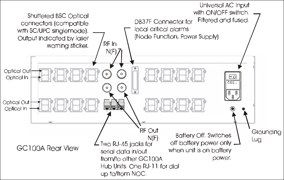
available with rails. Before turning on the AC (or DC) power to the chassis, connect the fiberoptic cables at
the rear panel.
During installation of the fiberoptic cables, each fiber should have been labelled as to which Remote
Transceiver it is to be connected to and whether it is for transmit or receive. The transmit or downlink fibers
are connected to the optical outputs on the rear panel. These are the red connectors with the laser light
warning labels. Make sure that the connectors used are associated with an active plug-in installed in the
chassis.
For ease of installation, the cable has been terminated with the OptoClip optical connector. The optical
RF
IN RF
IN
RF
OUT RF
OUT
Alarms
OI
The cable clam
p
s at each corner
of the rear panel ease cable
management and help protect
the optical connectors from undue
strain.
The minimum bend radius of
the fiber is 2 inches (5 cm). Do
n
o
t
k
i
n
k
t
h
e
f
i
b
e
r
.
The optical connector for the
transmit (downlink) path
is red with the laser warning
label. The black connector
is for the receive path.
Figure 0. Connecting Fiberoptic Cables to Hub Shelf.

2-9
connectors for the Hub Shelf are SC/UPC so an OptoClip-to-SC/UPC adapter must be used. Alternatively,
use optical jumpers with an SC/UPC termination at one end and an OptoClip at the other to connect the Hub
Shelf to an optical patch panel (recommended). First, clean the tip of the connector on the cable according to
the procedures in 2.2.2 above. Lift the spring loaded cover on the Hub Shelf rear panel connector and push in
the SC/UPC cable connector until firmly seated (the connector may or may not “click” into place; do not push
too hard). You may want to use the cable clamps located on the four corners of the rear panel to manage and
protect the cables.
The front panel of each Plug-In has two 1.75” x 0.5” (4.4 cm x 1.3 cm) outlines labelled A and B which can
be used to affix standard “address” size labels (Avery 5167) to designate which Remote Transceiver is
connected to that path.
Do not connect the RF cables yet.
If more than one Hub Shelf is being used, connect the SERIAL DATA ports together using CAT-5 jumpers
with RJ-45 connectors. The two SERIAL DATA ports on the rear panel are coonected together; two are
provided to permit the use of simple jumpers when daisy-chaining several units.
Connect the LINE port to a POTS telephone jack for the dial-up modem connection.
If it is being used, connect the chassis to the local OA&M interface by way of the 37 pin D-Sub connector on
the rear panel of the Hub Shelf (see section 2.3: System Alarms).
Turn on the chassis power. Powering up the chassis will “light up” the fiber allowing those installing the
Remote Transceivers to identify the transmit and receive cables using an IR sensitive card (see
Recommended Tools) to see which fiber is emitting light. The fiber emitting light at the Remote Transceiver
end is the transmit path and is connected to the OPTICAL IN connector on the Remote Transceiver (after
proper cleaning; see section 2.2.2).
If the transmit RF signal from the BTS or repeater is to be routed to all the plug-ins in both sides of the Hub
Shelf, connect the external 1:2 RF splitter supplied with the Hub Shelf to both RF IN ports on the rear panel.
If the receive RF signals from all of the plug-ins in both halves of the Hub Shelf are to be routed to a single
receive port on the BTS or repeater, connect the other 2:1 RF combiner to both of the RF OUT ports on the
rear panel. If one of the RF OUT ports is to be connected to the BTS or repeater receive diversity port, do
not connect the RF combiner.
Connect the RF OUT to the BTS or repeater receive port(s).
Before connecting the RF transmit cables from the BTS or repeater to the RF IN of the Hub Shelf, verify that
the BTS or repeater RF output power levels are consistent with the desired output power at the Remote
Power Supply and will not overdrive or damage the OfficeCell Plug-Ins. Connect the BTS or repeater RF
transmit cables to the Hub Shelf.
2.7 Installing the Remote Transceivers
Each Remote Transceiver is mounted above the false ceiling against the wall with the connectors pointing
down for easy access. In an area with no false ceiling, it can be mounted in the room near the ceiling with the
connectors pointing up. This permits a more aesthetic routing of the cables in the wall-ceiling corner. The
REMOTE TRANSCEIVER is connected to the Hub Shelf with a singlemode fiberoptic cable with a
maximum optical loss of 4 dB, including connectors and patch panels.
! The minimum bend radius of the fiber is 2 inches (5 cm). Be careful not to kink the fiber.
2-10
To mount the Remote Transceiver, first install the mounting bracket. Two mounting brackets are available.
One is smaller and accomodates a single Remote Transceiver. The other, larger bracket accomodates one
Remote Transceiver and one Remote Power Supply. The bracket is attached to a wall or bulkhead using #6
pahhead or M3.5 screws. The Remote Transceiver (and Power Supply, if applicable) are mounted on the
bracket by inserting the rear panel studs into the keyhole slots in the bracket. Each Unit is secured to the
bracket by threading the captive thumscrew (located at the connector end of the unit) into the threaded hole in
the tab on the bracket. See the figures below for more detail.
The Remote Transceiver takes +15 to +24 VDC power through a field-installable Molex connector. If the
Remote Power Supply is being used, the DC connection is provided by simply plugging in the DC cable from
the REMOTE POWER SUPPLY to the REMOTE TRANSCEIVER. The REMOTE POWER SUPPLY should
be powered through a sheilded AC power cable installed according to local building codes.
For DC versions , the terminals can take wires 18 AWG to 14 AWG. The choice will depend on the voltage
used and the distance from the power supply (see Specification, Electrical).
Next, install the indoor coverage antenna according to the manufacturer’s instructions. Connect the antenna to
the Remote Transceiver RF SMA connector using a flexible RF cable with VSWR < 1.5 : 1 at the frequencies
in use.
! RF SMA connectors should be tightened with a torque wrench set to 8 in-lbs. Do not
overti
g
hten!
Figure 3. Mounting the Remote Transceiver: Mounting Bracket.
Any antenna connected to this device must result in an ERP < 1.5W(800 and 900MHz) or <
3.0W
(
1
800
MH
z
and
1
900
MH
z)!

2-11
Connect the optical cable. The fiber for the transmit (downlink) path connects to the OPTICAL IN connector.
The fiber for the receive (uplink) path connects to the OPTICAL OUT connector (Green with laser DANGER
label). The fibers should be labelled accordingly during installation of the fiberoptic cables. If not, they can
be identified by turning the Hub Shelf power on with the plug-ins and fiberoptic cables installed. Then, use
an IR sensitive card (see Recommended Tools) to detect the light emitted from the transmit fiber. Point the
optical connector on each fiber at the card to see which fiber is emitting light (you see a glowing spot on the
card). This is the fiber for the transmit path. The other is for the receive path.
Knowing the desired output power level from each Remote Transceiver as determined by the network design,
the Output RF Power can be preset before the system is powered up. Given the rated maximum power from
the Remote Transceiver, the antenna gain an the loss in the RF cable, the output RF power is maximum when
the Output Power adjustment is set at 0. The static output power can be reduced by turning the adjustment.
The adjustment is indented and each indent changes the output power by 2 dB.
Once all connections have been made, turn on the AC power (or DC power, depending on the option used) to
Hub Shelf and Remote Transceivers. Before connecting the transmit RF input from the source, check that the
level is that needed for optimum signal to noise and distortion as determined in the network design (see Table
1 above). Connect the RF cables to the Hub Shelf.
WARNING: Do not look directly into the end of the fiberoptic connector. Laser light
is
invisible
and
can
cause
eye
damage.
! To prevent damage to the Hub Shelf plug-ins, do not exceed the maximum ratings for RF input to
the
H
ub
Shelf
!
3-1
3 Monitoring and Troubleshooting
3.1 Field Support Numbers
The tips given below should help pinpoint most link problems. Often, problems are a result of a poor optical
interface which is easily fixed by properly seating a connector or cleaning the connector. There are no user
serviceable parts in the OFFICECELL. Faulty units must be returned to Repeater Technologies Inc. for repair
or replacement. For technical support call 800-938-1901 in the U. S. or 408-747-1946.

3-2
3.2 Troubleshooting Tips
Alarms Probable Cause Action*
Node Function 1. Remote Transceiver Downlink Tx
amplifier chain failure
2. Pilot tone oscillator malfunction
3. Pilot tone detector malfunction
1. If Remote Transceiver Rcvd
Opt Pwr LED is OFF, this
indicates downlink amplifier
chain failure: replace Remote
Transceiver.
2. Repair/replace failed Plug-In
3. Repair/replace failed Plug-In
1. Node Function
2. Received Opt Pwr
Low (Remote
Transceiver)
1. Problem in downlink fiber path:
optical loss too high: fiber run is
too long, connector not seated
properly, damaged or in need of
cleaning, damaged splice
2. Remote Transceiver photodiode
failure
1. Check Rcvd Optical
Power LED at Remote
Transceiver. If active
(Yellow), disconnect
downlink fiber and check
optical output with light
sensitive card. If no light
detected, inspect fiber
path, esp. any connector
recently disconnected.
Inspect for proper
seating. Clean
connectors. If necessary,
disconnect fiber from
OFFICECELLand check
fiber path with OTDR to
locate problem.
2. If fiber is OK, indicates
Remote Transceiver
photodiode failure:
replace Remote
Transceiver.
1. Node Function
2. Received Opt Pwr
Low (Plug-In)
1. Remote Transceiver laser failure
2. Problem in uplink fiber path:
optical loss too high: fiber run is
too long, connector not seated
properly, damaged or in need of
cleaning, damaged splice
3. Plug-In photodiode failure
1. Check Laser Alarm in
Remote Transceiver. If
active (Red), replace
Remote Power Supply.
2. If not, inspect fiber path,
esp. any connector
recently disconnected.
Inspect for proper
seating. Clean
connectors. If necessary,
disconnect fiber from
OFFICECELLand check
fiber path with OTDR to
locate problem.
3. Replace Plug-In

3-3
1. Node Function
2. Received Opt Pwr
Low
3. Laser Pwr Low (both
Hub Shelf Plug-In and
Remote Transceiver)
Failing or failed Plug-In laser Replace Plug-In
Laser Pwr Low (Hub
Shelf Plug-In) Failing laser Replace unit Hub Shelf Plug-In
1. Laser Pwr Low (either
in Hub Shelf Plug-In or
Remote Transceiver)
2. Received Opt Pwr
Low (opposite end)
Failing laser Repair/replace unit (Hub Shelf
Plug-In or Remote Transceiver)
Received Opt Pwr Low
(Hub Shelf Plug-In) 1. Failed/failing laser in Remote
Transceiver
2. Optical loss too high, link may not
be operating within
specifications. Fiber path may be
too long. Problem in fiber path:
connector not seated properly,
damaged or in need of cleaning,
damaged splice
1. Inspect Remote
Transceiver for Laser
Alarm LED on (Red). If
so, replace Remote
Transceiver
2. Inspect fiber path, esp.
any connector recently
disconnected. Inspect for
proper seating. Clean
connectors. If necessary,
disconnect fiber from
system and check fiber
path with OTDR to
locate problem.
Hub Shelf: Main Power
Alarm Main Power Supply Failure (voltage
dropped more than 1 V from +15V) Replace Main Power Supply
Hub Shelf: Backup
Power Supply Alarm Backup Power Supply Failure (voltage
dropped more than 1 V from +15V) Replace Backup Power Supply
Battery Alarm 1. During battery only operation this
would be normal after unit has been on
for 10 to 20 minutes. Should go off
after main power is restored and
battery charges up.
2. If main and/or backup power supplies
are OK, this indicates battery or
recharging circuit failure
1. No Problem
2. Replace Chassis
* All repairs of OFFICECELL components must be performed by the factory