Repeater Technologies OC80002 Distributed Antenna Systems User Manual users manual
Repeater Technologies Inc Distributed Antenna Systems users manual
UserManual.wiki
>
Repeater Technologies
>
OC80002 User Manual
>
users manual
Contents
1.
users manual
2.
Revised manual page to include rf exposure statement
users manual
Navigation menu
Upload a User Manual
Namespaces
Wiki Guide
HTML
PDF
Info
Views
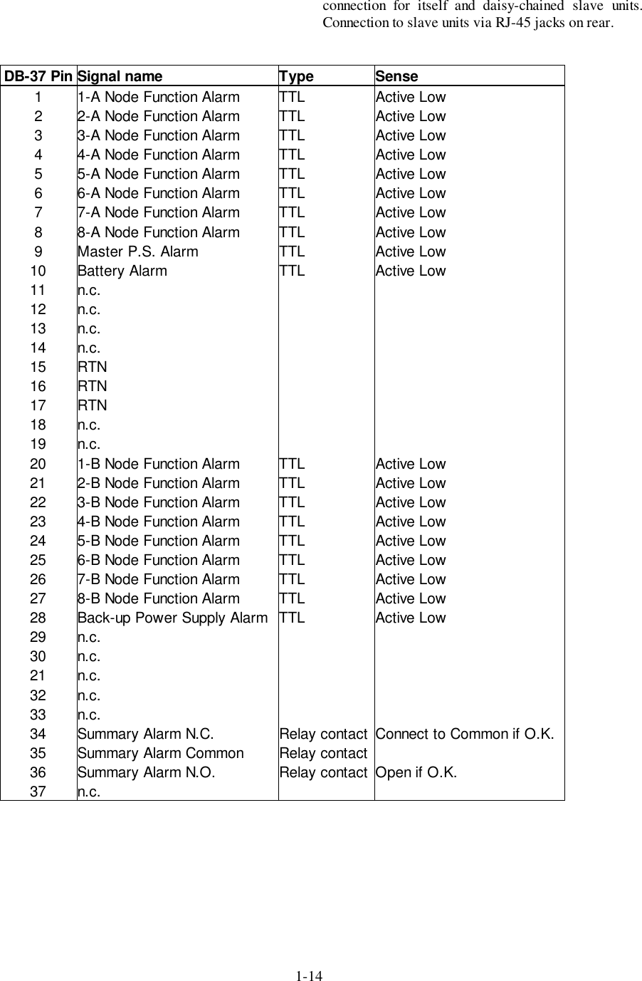
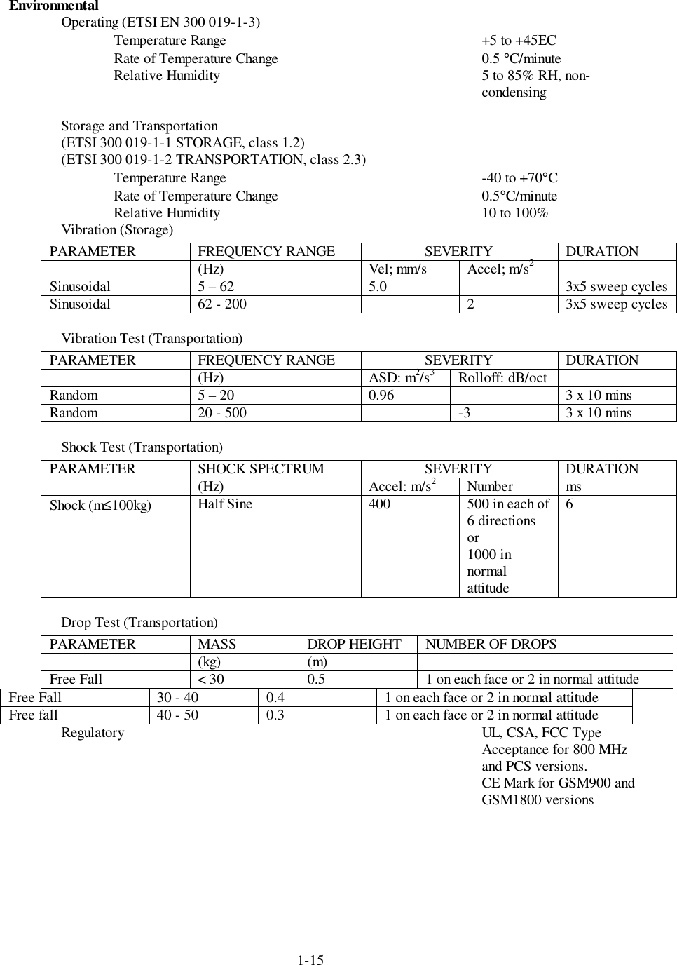
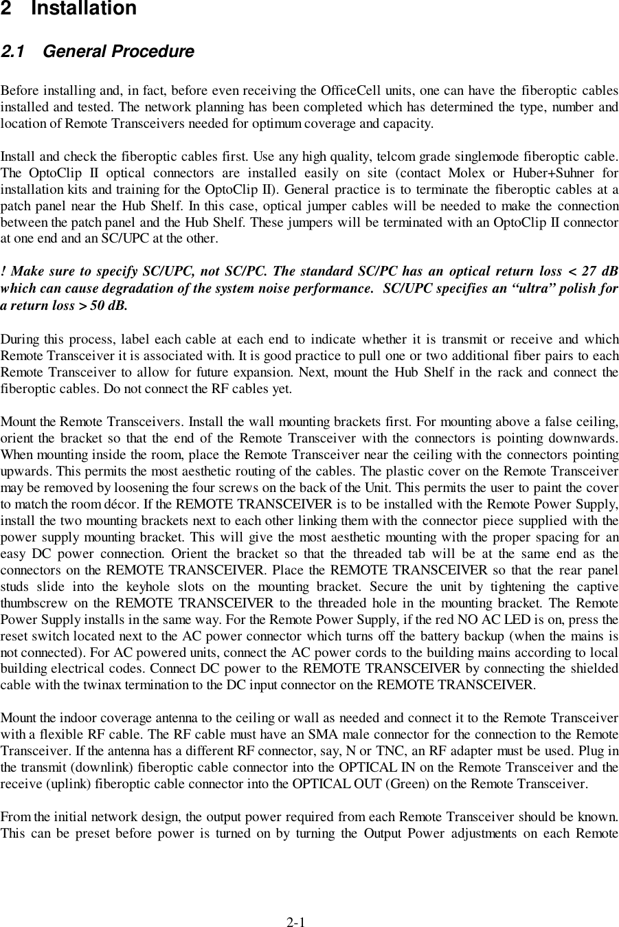
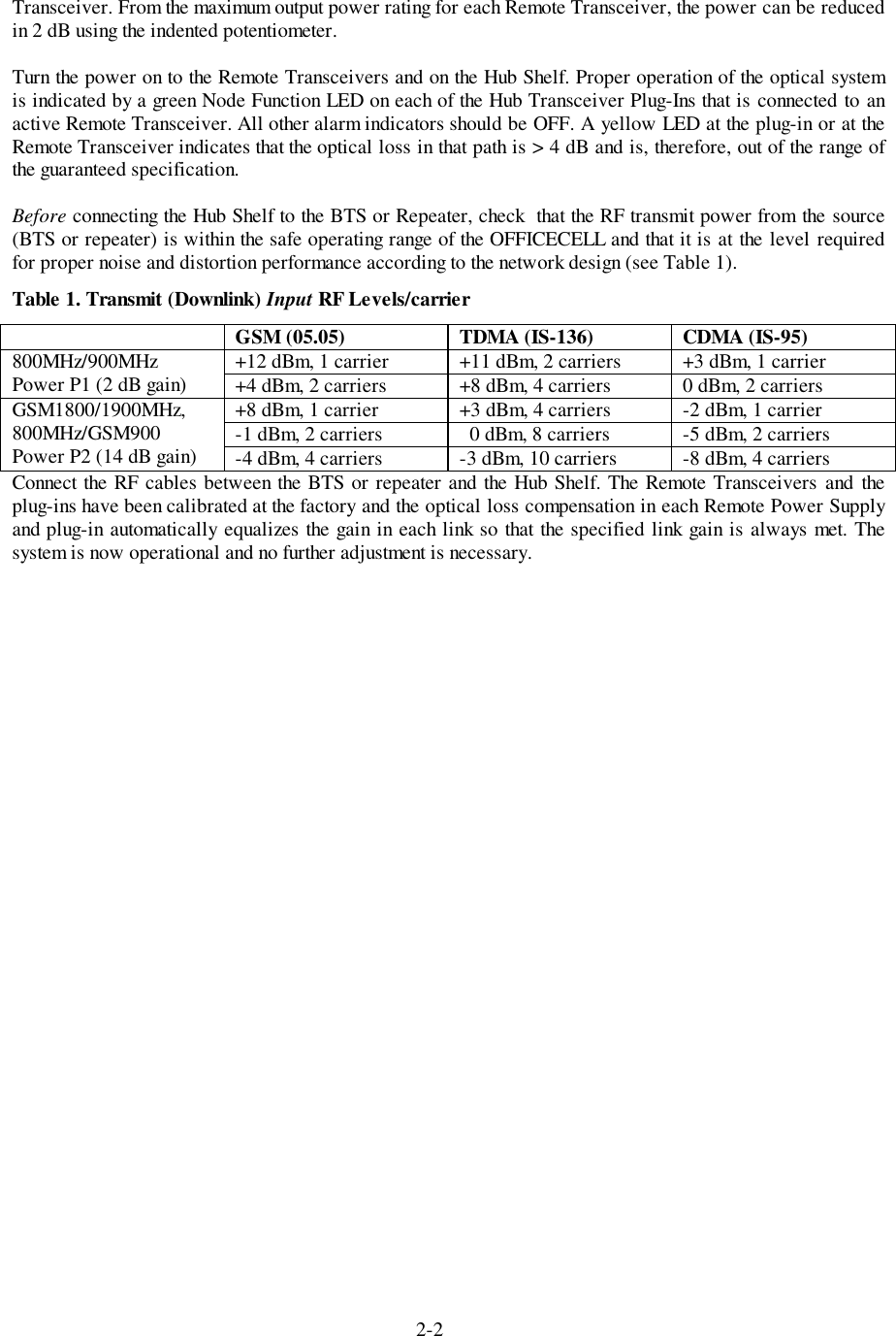
User Manual
Discussion / Help
Navigation