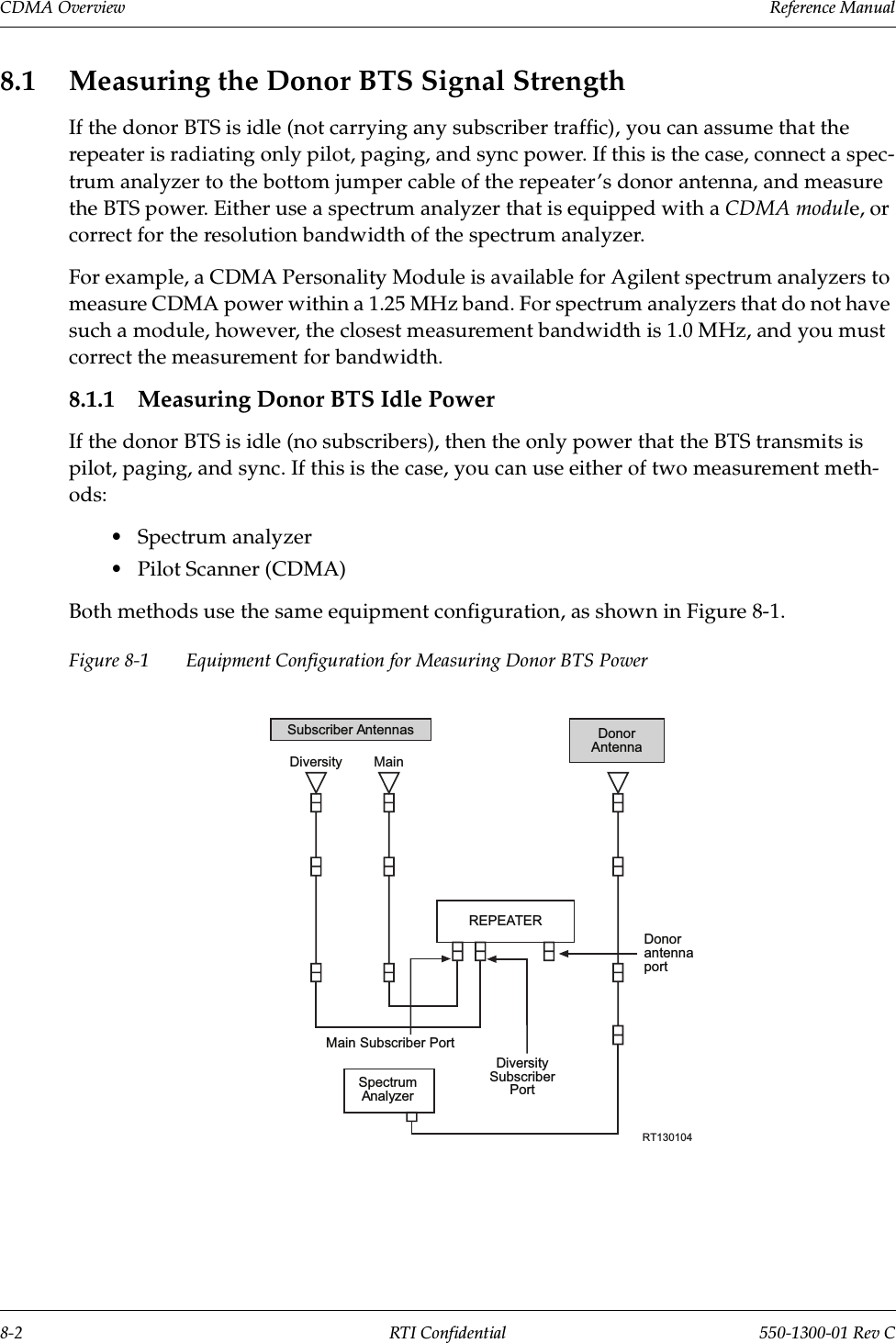
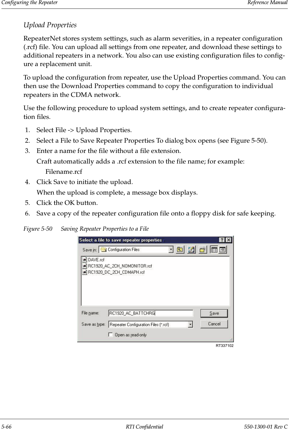
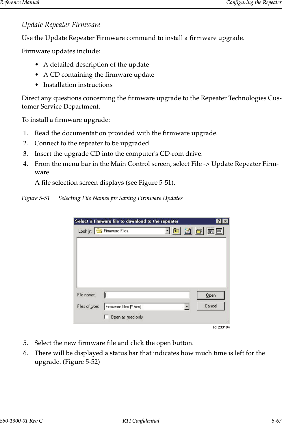
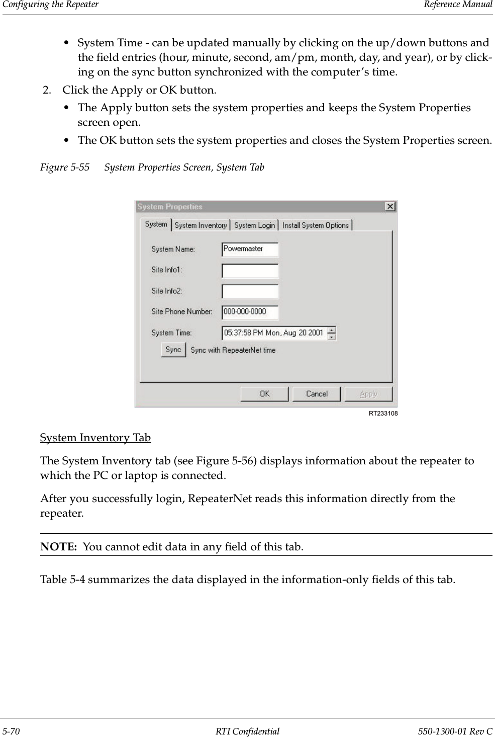
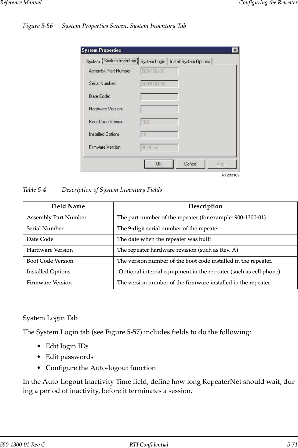
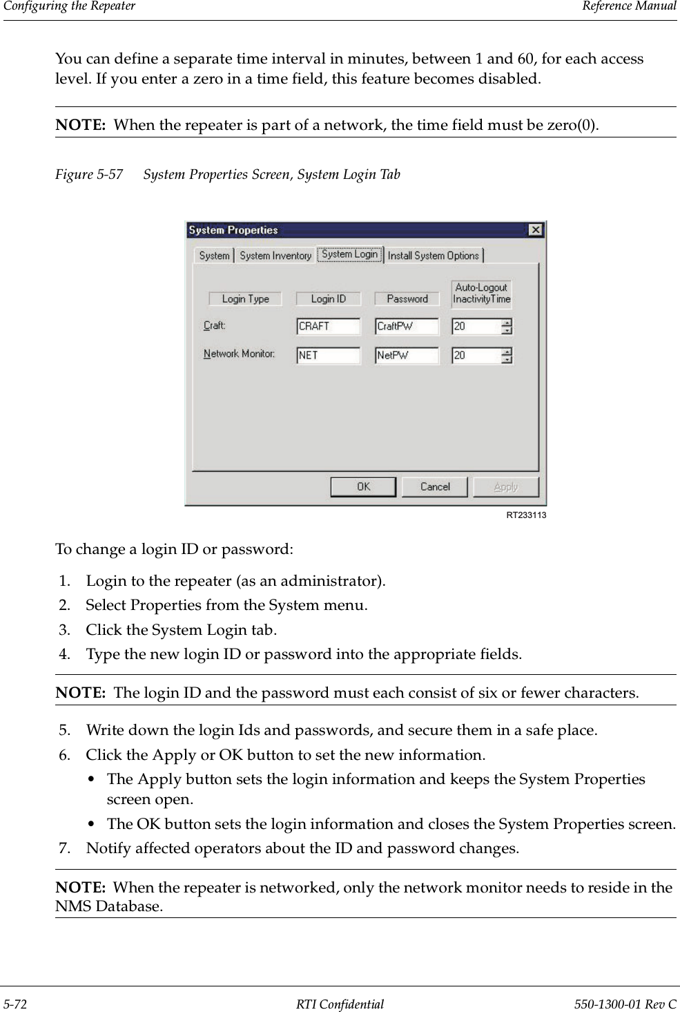
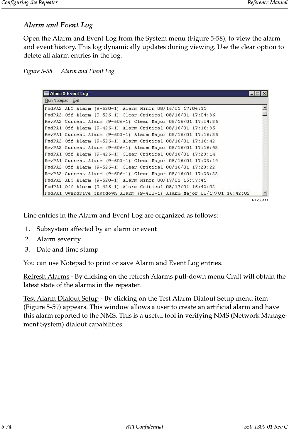
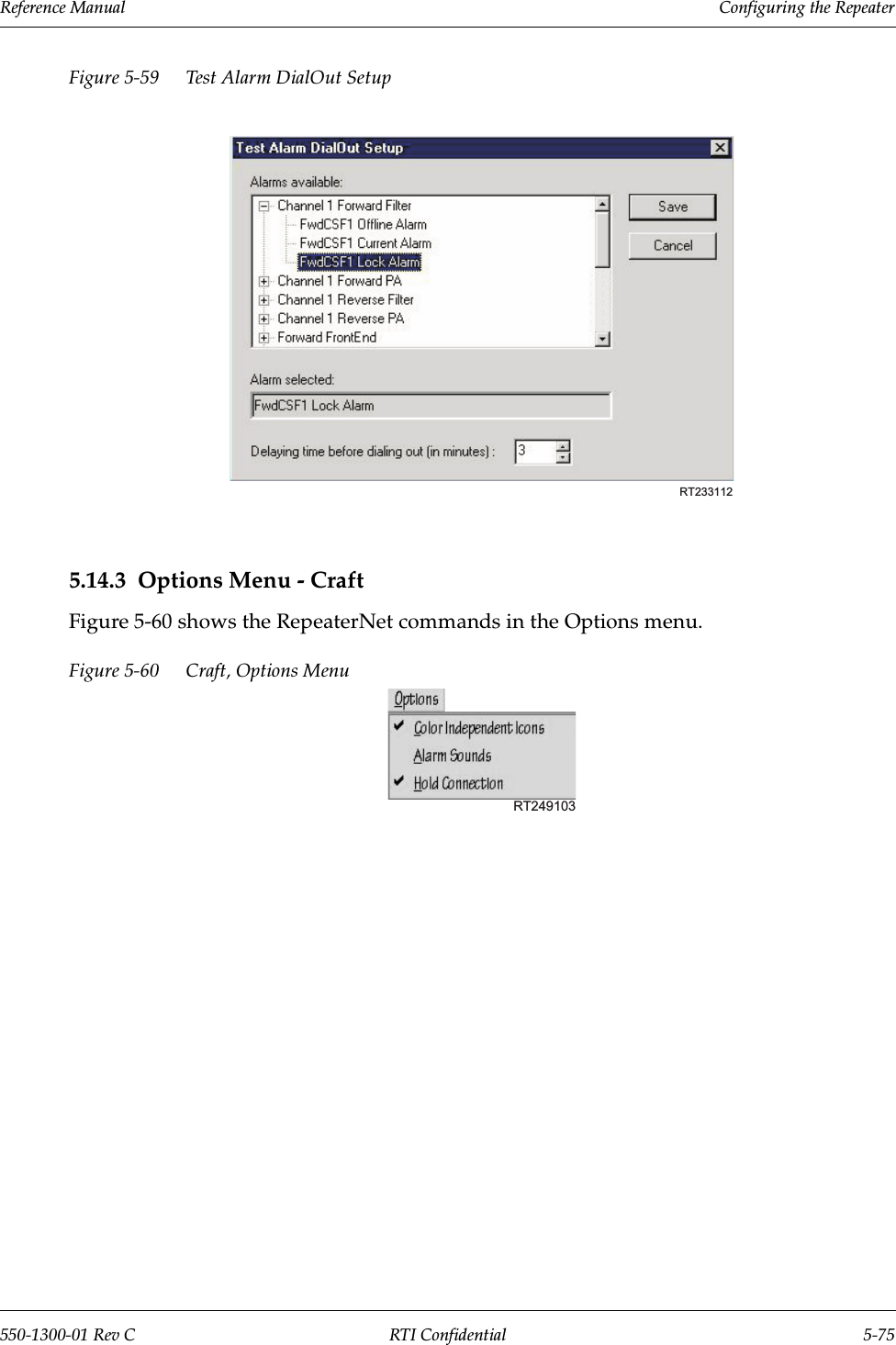
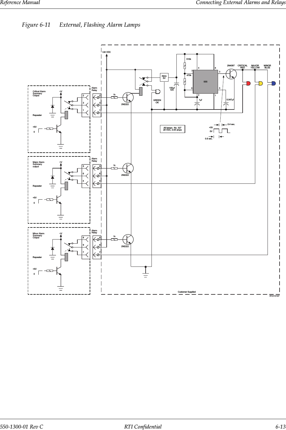
Repeater Technologies RC1930C PCS Repeater Amplifier User Manual Exhibit 7 Manual
Repeater Technologies Inc PCS Repeater Amplifier Exhibit 7 Manual
UserManual.wiki
>
Repeater Technologies
>
RC1930C User Manual
Users manual
Navigation menu
Upload a User Manual
Namespaces
Wiki Guide
HTML
PDF
Info
Views
User Manual
Discussion / Help
Navigation

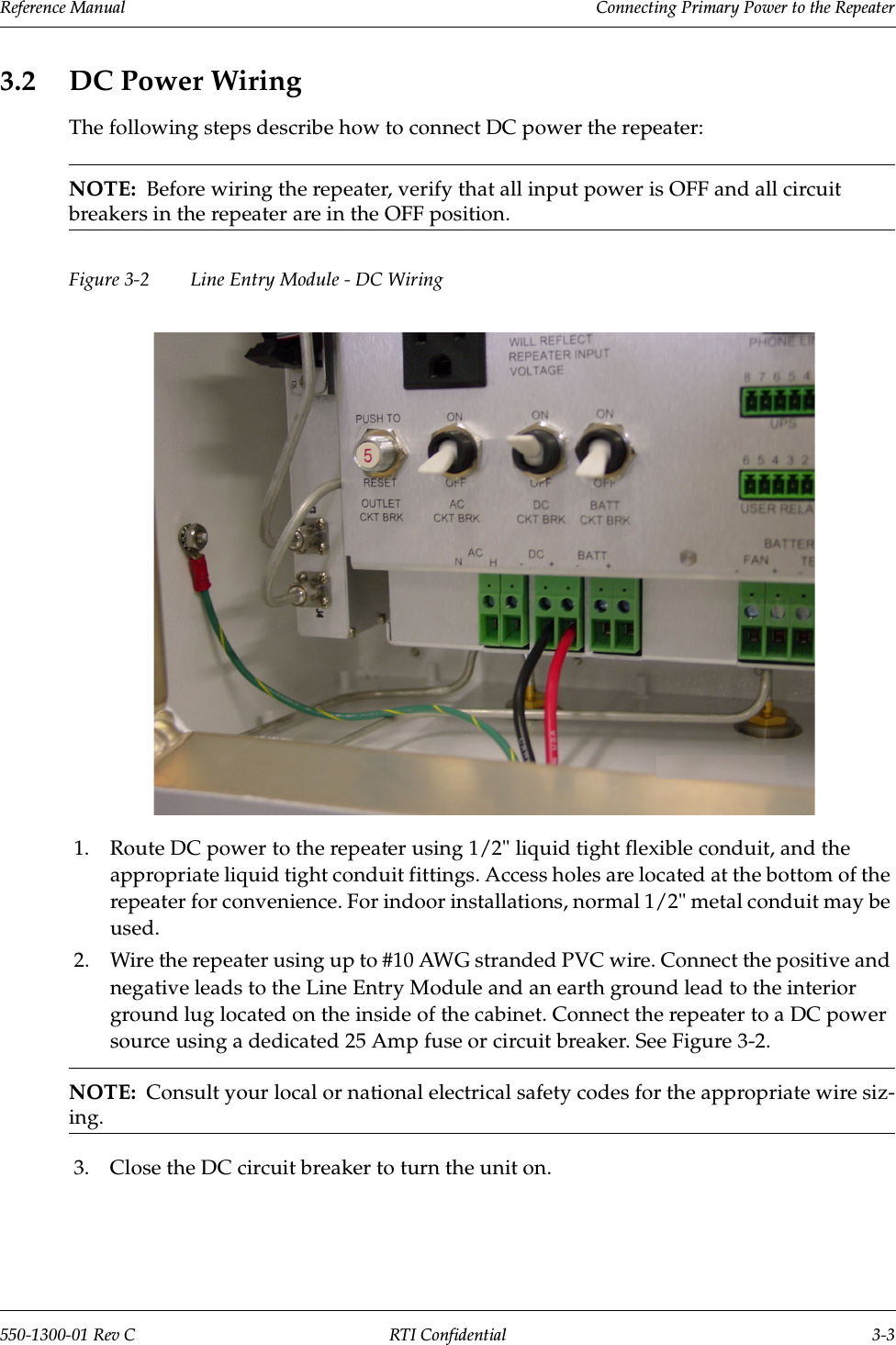

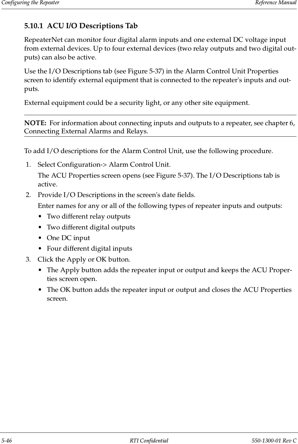
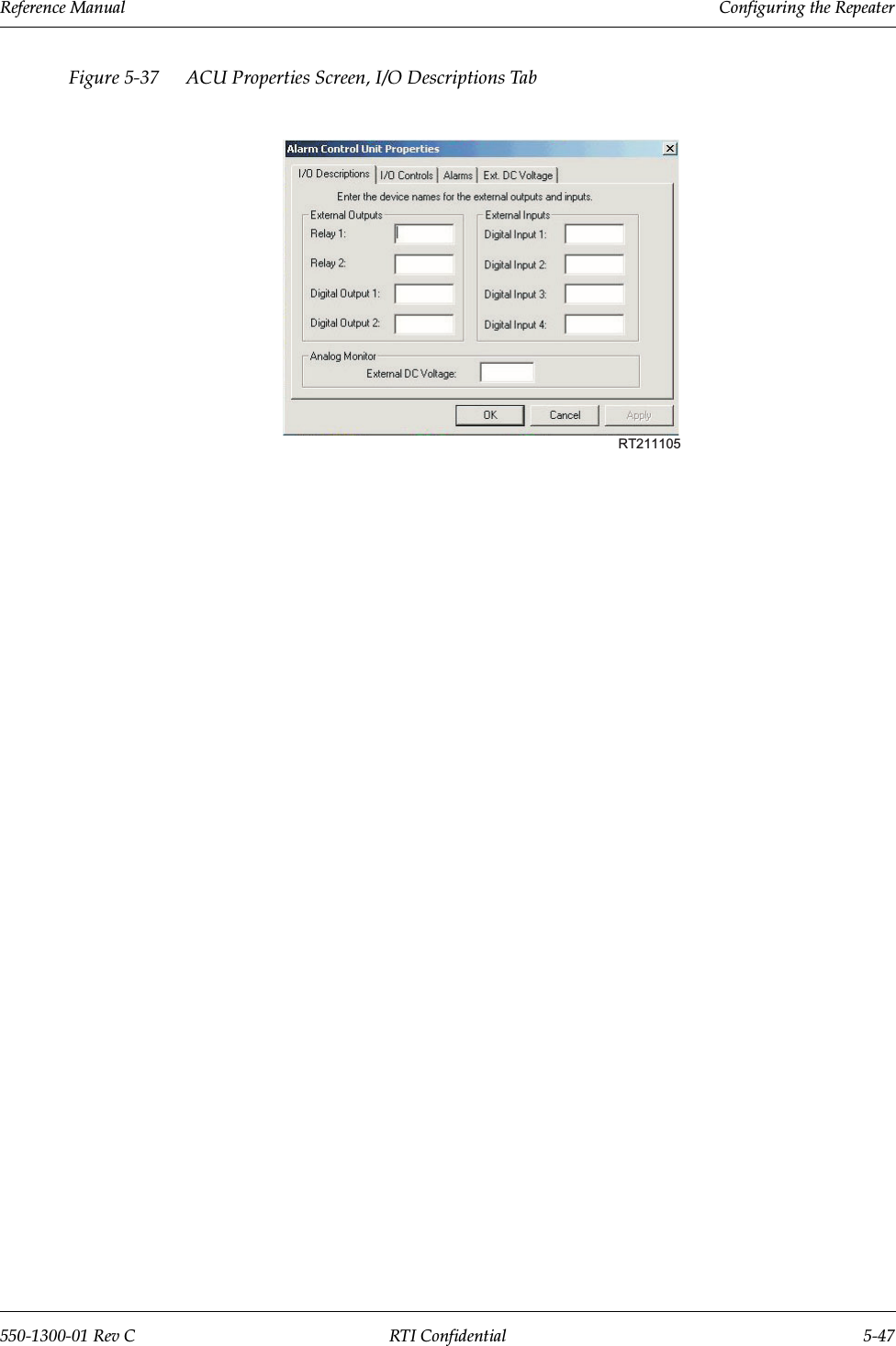
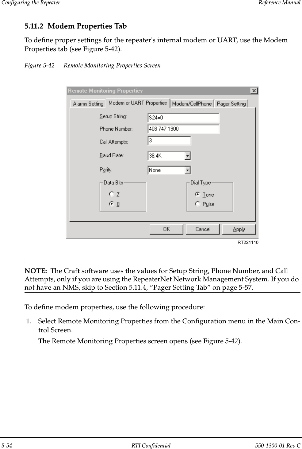
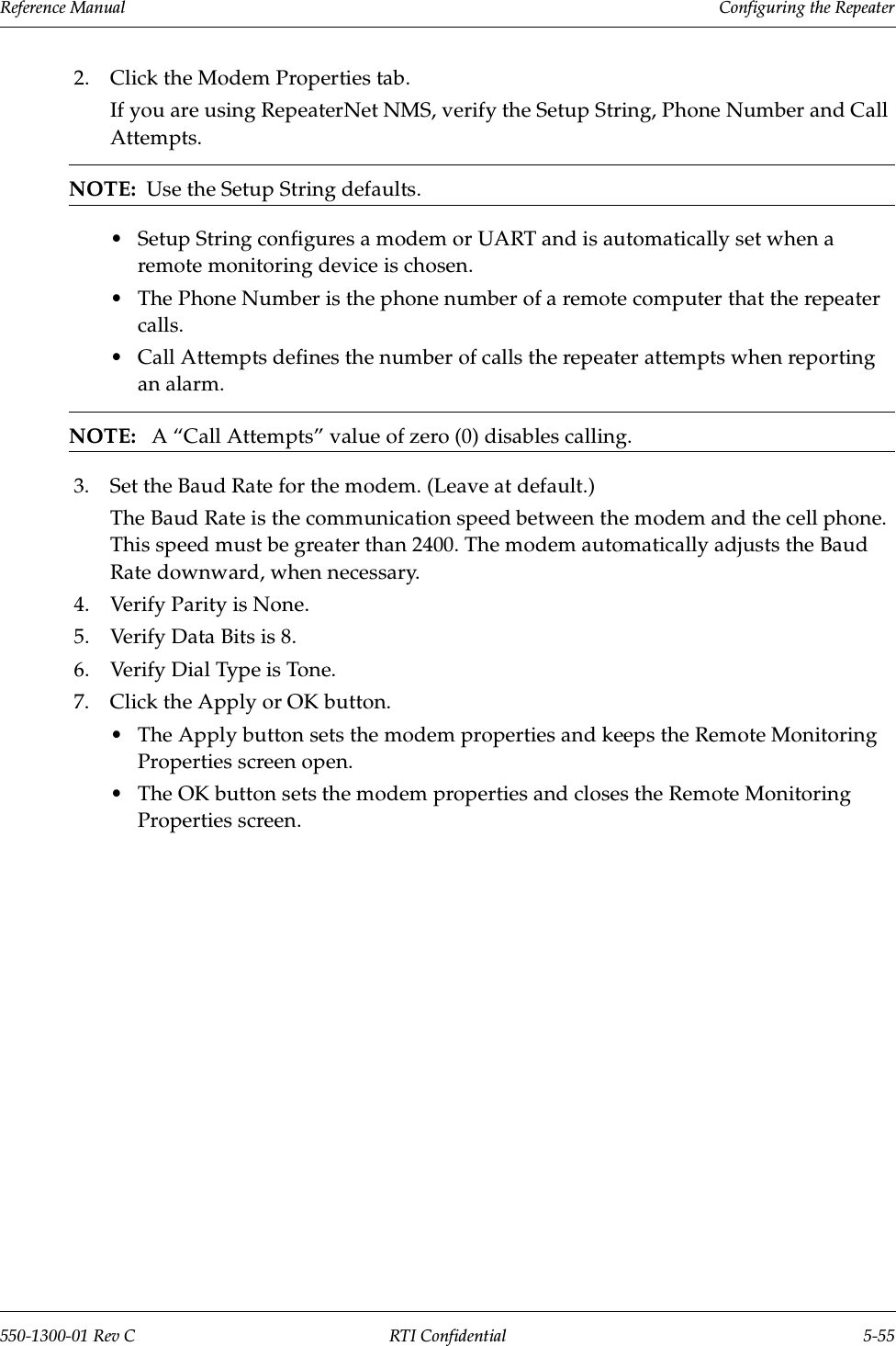
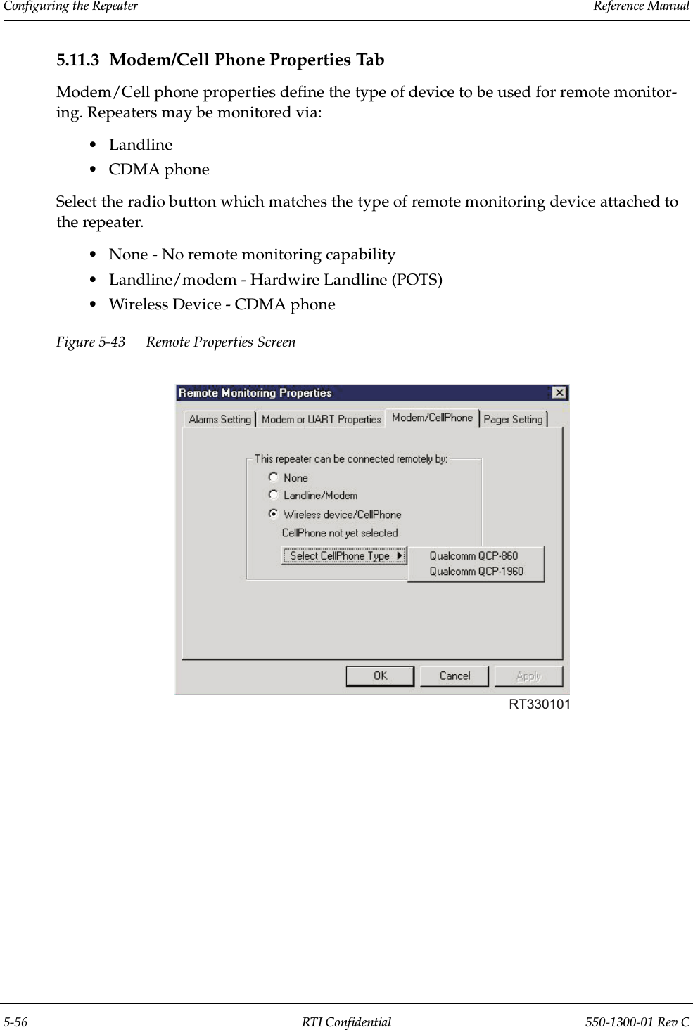

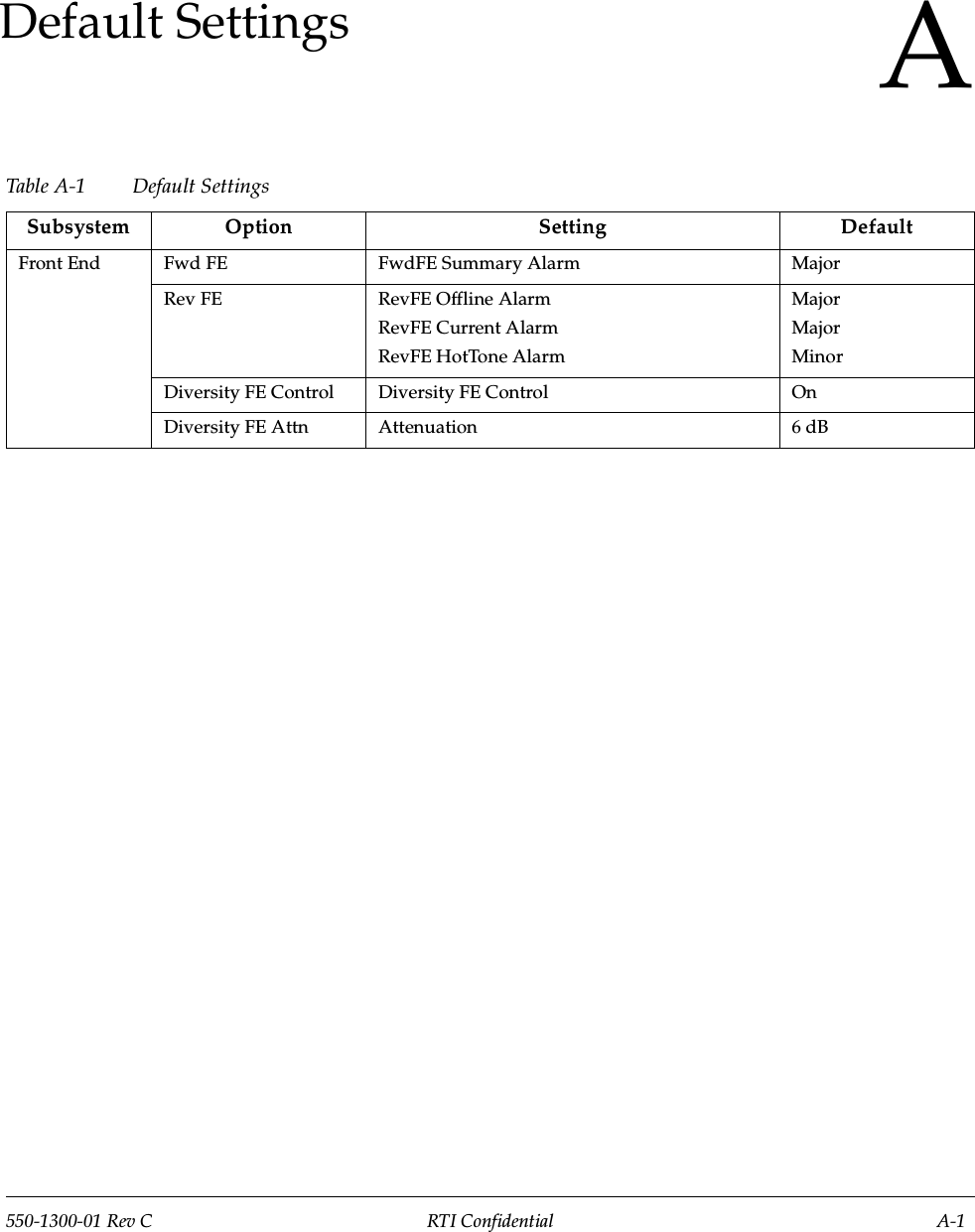
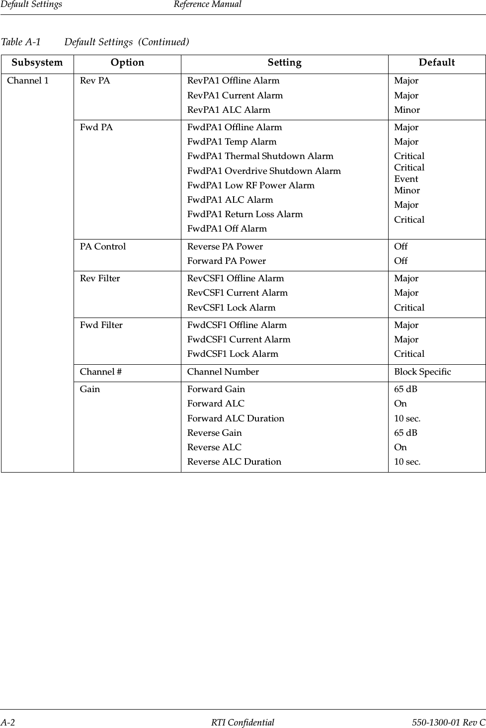
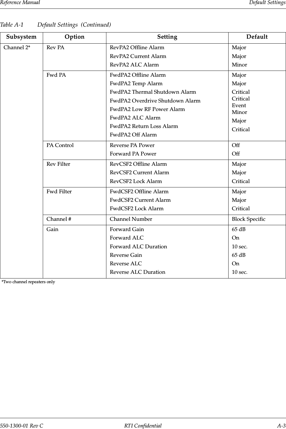
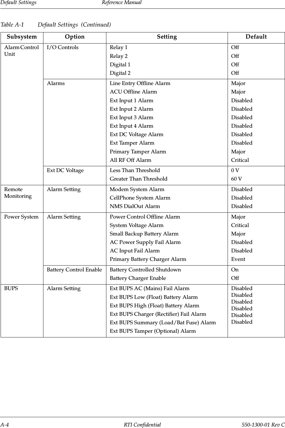
![Reference Manual Final Testing and Optimization550-1300-01 Rev C RTI Confidential 7-37.1.3 Channel Search Window Width for Reverse Link AccessThe mobile station searches the forward link TOA probability space for new pilot offsets. A similar search process occurs at the base station.The base station modem chip (CSM) also contains a searcher. Both the access channel and the traffic channel use this searcher to determine the TOA of the mobile's energy. Because the access channel does not know how far an originating mobile is from the base station, it must search the entire TOA probability space associated with the cell's maximum radius.For example, if the cell has a maximum radius of 20 chips, then the searcher must search the range of relative TOA, from near zero chip delay (for very close mobiles), to delays as great as 40 chips.NOTE: The round trip delay is the important variable, because the mobile is "phase locked" to the PN sequence of the down-link (forward link) path. Also, the TOA (round-trip delay) of the base station is twice the one-way delay.The cell radius plays a central role in determining the required width for the access-chan-nel search window. Most CDMA network manufacturers derive all of the required search window parameters from a simple parameter, called Cell_Radius or something similar. Usually, if you set this parameter to the maximum cell radius, the Method Of Repeater Engineering (M.O.R.E.) automatically calculates and updates all corresponding parame-ters (such as preamble size, PROBE_RAN_N, and so on).NOTE: You must set this parameter properly. An incorrect setting can limit the range of access to the base station via the repeater.The setting for this parameter is simply the sum of the donor link radius, the repeater delay in miles, and the maximum repeater coverage range as shown in the following equation:Cell_Radius(miles) = Donor_Path_Length(miles)+[Repeater_Delay(µs)]*0.186+Repeater_Radius(miles)If the equipment manufacturer does not provide a Cell Radius type parameter, or if you need more information on this subject, please contact the Repeater Technologies Applica-tion Engineering Group.](https://usermanual.wiki/Repeater-Technologies/RC1930C/User-Guide-241511-Page-147.png)