Repeater Technologies RC1930C PCS Repeater Amplifier User Manual Exhibit 7 Manual
Repeater Technologies Inc PCS Repeater Amplifier Exhibit 7 Manual
Users manual
550-1300-01
Revision C
April 2002
Reference Manual
• RC19-1X10 Network Repeater
•RC19-1X15 Network Repeater
• RC19-2X10 Network Repeater
•RC19-2X15 Network Repeater

R e f e r e n c e M a n u a l
ii RTI Confidential 550-1300-01 Rev C
© 2002 Repeater Technologies, Inc. All rights reserved.
All figures, tables, and text in this manual are the property of Repeater Technologies, Inc.
(RTI).
This manual provides product, ordering, installation, testing, maintenance, and applica-
tion information for this product. This information is confidential; any unauthorized
duplication, distribution, or electronic transfer of the materials to anyone, other than to
Repeater Technologies’ authorized employees, is forbidden.
By accepting this Reference Manual from Repeater Technologies, you agree to hold, in
strictest confidence, the materials and information herein, and not to use or to disclose
this information to any person, firm, or corporation, without the express written permis-
sion of Repeater Technologies. “Confidential Information” refers to any Repeater Tech-
nologies proprietary information, technical data, know-how, product plans, products,
services, designs, drawings, hardware configuration information, and tables featured in
this manual.
This manual assumes that the installation will be performed by a qualified engineer.
Repeater Technologies, Network Repeater, and RepeaterNet are trademarks of RTI.
Microsoft and Windows are registered trademarks of Microsoft Corporation. Other
brands and their products are trademarks or registered trademarks of their respective
holders.
FCC Identifiers: EK2RC1920C, TBD
Industry Canada
Certificate Nos. 15054, TBD
Certification Nos. 2884332351, TBD
Repeater Technologies, Inc.
Corporate Headquarters (8 a.m. to 5p.m. Pacific Standard Time, Monday-Friday)
1150 Morse Avenue
Sunnyvale, CA 94089 USA
(408) 747-1900
(888) 747-1515 (USA and Canada only)
Fax+1 408 747-0375
Customer Service (7 days a week, 24 hours per day)
(408) 747-1946
(888) 747-1515 (USA and Canada only)
www.repeaters.com

Reference Manual
550-1300-01 Rev C RTI Confidential iii
Change Record
Revision/Issue Date Description of Change Affected Pages
Issue 1 10/09/01 Initial draft. ALL
Issue 2 12/01/01 Revise document. ALL
Revison A 1/18/02 Production release. ALL
Revision B 3/7/02 Revise document. ALL
Revision C 4/9/02 Add RC19-1X15 and RC19-2X15 Models ALL

R e f e r e n c e M a n u a l
iv RTI Confidential 550-1300-01 Rev C

Reference Manual Table of Contents
550-1300-01 Rev C RTI Confidential v
Table of Contents
Chapter 1 Unpacking and Inventory
1.0 Receiving and Inspecting the Repeater ..................................................... 1-1
1.1 Equipment Required for Installation ......................................................... 1-2
Chapter 2 Mounting the Repeater
2.0 Installation Overview................................................................................... 2-1
2.1 Mounting the Repeater ................................................................................ 2-3
Chapter 3 Connecting Primary Power to the Repeater
3.0 Introduction ................................................................................................... 3-1
3.1 AC Power Wiring.......................................................................................... 3-2
3.2 DC Power Wiring.......................................................................................... 3-3
3.3 Wiring an External Back-up Power Supply .............................................. 3-4
3.4 Grounding...................................................................................................... 3-9
Chapter 4 Installing Antennas
4.0 Moisture Protection for Antenna Connections......................................... 4-1
4.1 Antenna Configurations .............................................................................. 4-3
4.2 Antenna Cables ............................................................................................. 4-9
4.3 Lightning Protection..................................................................................... 4-9
4.4 Back-Beam Antennas and Directional Couplers .................................... 4-11
4.5 Measuring Antenna Isolation.................................................................... 4-11
4.6 Sweeping Antenna Cables......................................................................... 4-15
Chapter 5 Configuring the Repeater
5.0 RepeaterNet Craft Software ........................................................................ 5-1
5.1 Minimum System Requirements ................................................................ 5-1
5.2 Installation Procedure .................................................................................. 5-2
5.3 Configuring the Repeater Connection ....................................................... 5-3
5.4 Starting Craft ................................................................................................. 5-6
5.5 Craft Main Control Screen........................................................................... 5-7
5.6 Status Reporting............................................................................................ 5-8
5.7 Configuring Repeater Properties/Alarm Severities .............................. 5-27
5.8 Front End Properties .................................................................................. 5-30

Table of Contents Reference Manual
vi RTI Confidential 550-1300-01 Rev C
5.9 Channel1 and Channel2 Properties.......................................................... 5-33
5.10 Alarm Control Unit Properties.................................................................. 5-45
5.11 Remote Monitoring Properties.................................................................. 5-52
5.12 Power System Properties ........................................................................... 5-60
5.13 Back-up Power System (BUPS) Properties.............................................. 5-62
5.14 RepeaterNet Menu Commands ................................................................ 5-64
Chapter 6 Connecting External Alarms and Relays
6.0 Overview ........................................................................................................ 6-1
6.1 Back-up Power System (BUPS) Monitoring.............................................. 6-3
6.2 User Controlled Inputs and Outputs ......................................................... 6-3
6.3 User Controlled Relays ................................................................................ 6-8
6.4 Alarm Controlled Relays ........................................................................... 6-11
Chapter 7 Final Testing and Optimization
7.0 Link Engineering Considerations............................................................... 7-1
7.1 System Timing Issues ................................................................................... 7-1
7.2 Drive Testing Requirements........................................................................ 7-6
Chapter 8 CDMA Overview
8.0 Introduction ................................................................................................... 8-1
8.1 Measuring the Donor BTS Signal Strength ............................................... 8-2
Chapter 9 Technical Specifications
9.0 Specifications ................................................................................................. 9-1
9.1 Ordering Information................................................................................... 9-4
9.2 Technical Services ......................................................................................... 9-6
9.3 Customer Support......................................................................................... 9-6
Appendix A Default Settings
Appendix B Glossary

Reference Manual List of Figures
550-1300-01 Rev C RTI Confidential vii
List of Figures
Chapter 2 Mounting the Repeater
Figure 2-1 Typical Repeater Installation..................................................................... 2-2
Figure 2-2 Rear Mounting Bracket .............................................................................. 2-3
Figure 2-3 Guide Bolt and Slot..................................................................................... 2-5
Figure 2-4 Pole Mounting Hardware .......................................................................... 2-8
Figure 2-5 Pole Mount - Side View ............................................................................. 2-9
Chapter 3 Connecting Primary Power to the Repeater
Figure 3-1 Line Entry Module - AC Wiring .............................................................. 3-2
Figure 3-2 Line Entry Module - DC Wiring .............................................................. 3-3
Figure 3-3 Simplified BUPS-25/80 Block Diagram, RTI P/N 250-1011-07............ 3-5
Figure 3-4 Front Panel of the BUPS-25/80 Charger-Rectifier ................................. 3-7
Figure 3-5 Wiring Connections from the Repeater to a BUPS-25/80..................... 3-8
Figure 3-6 Location of External Ground Lug............................................................. 3-9
Figure 3-7 Typical System Ground ........................................................................... 3-10
Chapter 4 Installing Antennas
Figure 4-1 N-Type Antenna Connectors, Looking Up From the Bottom of the
Repeater Cabinet ........................................................................................ 4-2
Figure 4-2 RF Connector Cable with Vapor Wrap.................................................... 4-2
Figure 4-3 Dual Polarized Subscriber Antenna Configuration ............................... 4-4
Figure 4-4 Two Vertically Polarized Subscriber Antennas...................................... 4-5
Figure 4-5 Back-Beam Antenna Configuration ......................................................... 4-6
Figure 4-6 Non-Diversity Antenna Configuration.................................................... 4-7
Figure 4-7 Dual Direction Antenna Configuration ................................................... 4-8
Figure 4-8 Lightning Arrestor, Grounding, and Repeater RF Cabling ................ 4-10
Figure 4-9 Equipment Setup for Measuring Antenna Isolation............................ 4-12
Figure 4-10 Antenna Isolation Measurement - Equipment Configuration ........... 4-13
Chapter 5 Configuring the Repeater
Figure 5-1 Startup Screen.............................................................................................. 5-2
Figure 5-2 Starting the RepeaterNet Administrator ................................................. 5-3
Figure 5-3 RepeaterNet Admin.................................................................................... 5-3
Figure 5-4 RepeaterNet Admin, Login Setting shown ............................................. 5-4
Figure 5-5 RepetaerNet Craft Start-up Window ....................................................... 5-6
Figure 5-6 Craft Main Control Screen ......................................................................... 5-7
Figure 5-7 Forward Front End Status Window ....................................................... 5-10
Figure 5-8 Forward Channel Select Filter (CSF) Status .......................................... 5-11
Figure 5-9 Forward Power Amplifier (FPA) Status ................................................ 5-12
Figure 5-10 FPA Measurement .................................................................................... 5-13

List of Figures Reference Manual
viii RTI Confidential 550-1300-01 Rev C
Figure 5-11 Reverse Power Amplifier (RPA) Status ................................................. 5-14
Figure 5-12 RPA Measurement.................................................................................... 5-15
Figure 5-13 Reverse CSF Status.................................................................................... 5-16
Figure 5-14 RFE Status .................................................................................................. 5-17
Figure 5-15 RFE Measurement..................................................................................... 5-18
Figure 5-16 Alarm Control Unit (ACU) Status .......................................................... 5-19
Figure 5-17 ACU Measurement ................................................................................... 5-20
Figure 5-18 Remote Monitoring Status....................................................................... 5-21
Figure 5-19 Power System Status ................................................................................ 5-22
Figure 5-20 Power System Voltages display here ..................................................... 5-23
Figure 5-21 Power System Primary Battery ............................................................... 5-24
Figure 5-22 Primary Test Tab ....................................................................................... 5-25
Figure 5-23 BUPS Status................................................................................................ 5-26
Figure 5-24 Craft Pull-down menus............................................................................ 5-27
Figure 5-25 Front End Properties Screen, Forward FE Tab ..................................... 5-30
Figure 5-26 Front End Properties Screen, Reverse FE Tab....................................... 5-31
Figure 5-27 Front End Properties Screen, Diversity FE Tab .................................... 5-32
Figure 5-28 Channel Properties Screen, Reverse PA Tab......................................... 5-33
Figure 5-29 Channel Properties Screen, Forward PA Tab ....................................... 5-35
Figure 5-30 Channel Properties Screen, Channel PA Tab........................................ 5-37
Figure 5-31 Channel Properties Screen, Reverse Filter Tab..................................... 5-38
Figure 5-32 Channel Properties Screen, Channel Forward Filter Tab.................... 5-40
Figure 5-33 Channel Properties Screen, Channel # Tab ........................................... 5-42
Figure 5-34 Channel Properties Screen, Channel Gain Tab ALC On..................... 5-44
Figure 5-35 Channel Properties Screen, Channel Gain Tab ALC Off .................... 5-44
Figure 5-36 Alarm Control Unit................................................................................... 5-45
Figure 5-37 ACU Properties Screen, I/O Descriptions Tab..................................... 5-47
Figure 5-38 ACU Properties Screen, I/O Controls Tab............................................ 5-48
Figure 5-39 ACU Properties Screen, Alarms Tab...................................................... 5-50
Figure 5-40 ACU Properties Screen, External DC Voltage Tab............................... 5-51
Figure 5-41 Modem Properties Screen ........................................................................ 5-52
Figure 5-42 Remote Monitoring Properties Screen ................................................... 5-54
Figure 5-43 Remote Properties Screen ........................................................................ 5-56
Figure 5-44 Remote Monitoring Properties, Pager Settings .................................... 5-58
Figure 5-45 Power System Properties Screen, Alarm Setting.................................. 5-60
Figure 5-46 Power System Properties Screen, Battery Control Enable .................. 5-61
Figure 5-47 BUPS Properties Screen............................................................................ 5-63
Figure 5-48 Craft, File Menu ........................................................................................ 5-64
Figure 5-49 Downloading Repeater Configuration Files ......................................... 5-65
Figure 5-50 Saving Repeater Properties to a File....................................................... 5-66
Figure 5-51 Selecting File Names for Saving Firmware Updates ........................... 5-67
Figure 5-52 Firmware Download Window................................................................ 5-68
Figure 5-53 Download Completion Window ............................................................ 5-68
Figure 5-54 Craft, System Menu Pull-down Menu ................................................... 5-69
Figure 5-55 System Properties Screen, System Tab .................................................. 5-70
Figure 5-56 System Properties Screen, System Inventory Tab ................................ 5-71
Figure 5-57 System Properties Screen, System Login Tab ....................................... 5-72
Figure 5-58 Alarm and Event Log ............................................................................... 5-74
Figure 5-59 Test Alarm DialOut Setup ....................................................................... 5-75
Figure 5-60 Craft, Options Menu................................................................................. 5-75
Figure 5-61 Craft, Help Menu ...................................................................................... 5-77

Reference Manual List of Figures
550-1300-01 Rev C RTI Confidential ix
Figure 5-62 About Screen.............................................................................................. 5-77
Chapter 6 Connecting External Alarms and Relays
Figure 6-1 Digital Input Circuit - Typical................................................................... 6-3
Figure 6-2 Monitoring a Tower Hazard Light........................................................... 6-4
Figure 6-3 Typical DC Monitoring .............................................................................. 6-5
Figure 6-4 User-Controlled Digital Output - Typical ............................................... 6-6
Figure 6-5 Switching an Intrusion Alarm On and Off, Using Digital Output
Number 2 ..................................................................................................... 6-7
Figure 6-6 Typical Relay Output ................................................................................. 6-8
Figure 6-7 Controlling a Lamp, Using Relay Output Number 2 ............................ 6-9
Figure 6-8 Controlling a Fan or Blower, Using Relay Output Number 1............ 6-10
Figure 6-9 Alarm Summary Relay Output - Typical .............................................. 6-11
Figure 6-10 Critical Alarm Summary Relay, Controlling an External LED .......... 6-12
Figure 6-11 External, Flashing Alarm Lamps ............................................................ 6-13
Chapter 8 CDMA Overview
Figure 8-1 Equipment Configuration for Measuring Donor BTS Power............... 8-2

List of Figures Reference Manual
x RTI Confidential 550-1300-01 Rev C

Reference Manual List of Tables
550-1300-01 Rev C RTI Confidential xi
List of Tables
Chapter 1 Unpacking and Inventory
Table 1-1 Required Installation Equipment ............................................................. 1-2
Table 1-2 Accessory Kit Inventory P/N 091-1300-01.............................................. 1-3
Chapter 2 Mounting the Repeater
Table 2-1 Pole Mounting Kit (P/N 091-0215-01) ..................................................... 2-7
Table 2-2 Banding Kit (P/N 5653K12) ...................................................................... 2-7
Chapter 3 Connecting Primary Power to the Repeater
Table 3-1 Input Power Specifications ........................................................................ 3-1
Chapter 5 Configuring the Repeater
Table 5-1 Alarm Icons.................................................................................................. 5-9
Table 5-2 Configuration Menu ................................................................................. 5-28
Table 5-3 Alarm Severity Numbers......................................................................... 5-58
Table 5-4 Description of System Inventory Fields ................................................ 5-71
Table 5-5 Description of Color Independent Icons ............................................... 5-76
Chapter 6 Connecting External Alarms and Relays
Table 6-1 Input/Output Pin Descriptions ................................................................ 6-2
Chapter 9 Technical Specifications
Table 9-1 PCS Frequencies.......................................................................................... 9-1
Table 9-2 RF Characteristics ....................................................................................... 9-1
Table 9-3 Mechanical Characteristics ........................................................................ 9-2
Table 9-4 Noise Figure................................................................................................. 9-2
Table 9-5 Additional Characteristics ......................................................................... 9-2
Table 9-6 Alternate Power Options ........................................................................... 9-2
Table 9-7 RepeaterNet Alarm, Monitoring, and Control ....................................... 9-2
Table 9-8 Inputs and Outputs..................................................................................... 9-3
Table 9-9 LED Indicators............................................................................................. 9-3
Table 9-10 Electrical Characteristics ............................................................................ 9-3
Table 9-11 Spare Parts and Accessory Items.............................................................. 9-4
Table 9-12 Contents of Accessory Kit.......................................................................... 9-5
Appendix A Default Settings
Table A-1 Default Settings .......................................................................................... A-1

List of Tables Reference Manual
xii RTI Confidential 550-1300-01 Rev C

550-1300-01 Rev C RTI Confidential 1-1
1
Unpacking and Inventory
1.0 Receiving and Inspecting the Repeater
When you receive a repeater from Repeater Technologies, Inc. (RTI), immediately do the
following:
1. Unpack the repeater.
2. Inventory the contents against the packing list and note any missing items.
3. Inspect for shipping damage, especially for damage that might have been hidden by
the packaging. Pay particular attention to the following:
•Bent or dented sheet metal
•Loose or broken components
•Damaged or bent connectors
•Damaged or broken wiring or coaxial cables
•Missing or damaged contents of the accessory kit
•Missing or damaged optional equipment ordered with the repeater unit.
If any items are missing or damaged, perform all of the following steps:
1. Report any missing or damaged items by writing them on the shipping waybill.
2. Ask the delivery agent to sign the waybill for verification of the loss or damage.
3. Notify the transfer (shipping) company as soon as possible.
4. Submit a damage report to the shipping carrier.
5. Inform customer service at 1-800-938-1901.
NOTE: Save the original shipping carton and packing materials to reuse for any future
transport of the repeater unit. For example, a repeater might be moved to a new loca-
tion in a PCS network, or a damaged repeater might need to be returned to RTI.
Repeater must be transported with backplate. Packaging must be original or warranty
may be affected.

Unpacking and Inventory Reference Manual
1-2 RTI Confidential 550-1300-01 Rev C
1.1 Equipment Required for Installation
Table 1-1 lists required installation equipment RTI does not provide with a repeater.
These standard tools should be readily available from local suppliers of telephone, elec-
tronic, and/or computer equipment.
NOTE: Installing an RTI repeater requires a site plan. These documents define the
intended parameters of the cellular/PCS network project, including the repeater’s cov-
erage area, gain settings, and antenna location. If necessary, consult a network admin-
istrator for more information.
Table 1-1 Required Installation Equipment
Equipment Function
Site Plan/Network Engineering documentation Correctly configure the repeater to operate in the PCS/
Cellular network.
1/8 inch Small Flat Blade Screwdriver Use for AC input power and external alarm plugs.
Voltmeter, Fluke 75 or equivalent VOM Test voltage and power polarity.
Spectrum Analyzer and/or power meter Test RF power output.
RF Signal Generator (≥ 2 GHz) Test antenna isolation.
Pilot scanner (optional) Measure donor base station receive power.
Type N (m) 50-ohm Termination, 20 W (3 ea.) Terminate antenna ports during off-air testing.
Mounting Hardware Mount repeater, antennas and coax cables.
Electrical Wiring Equipment (as needed) Connect external power to Repeaters.
Laptop Computer (Win95, 98, ME, NT, 2000) Configure, control and monitor the repeater through
the RepeaterNet Craft port.
Pole Mounting Tightening/Crimping Tool (for
pole mounting only)
Mount the repeater to a pole and secure pole mounting
straps.
Coax Jumper Cables Type N (male to male) calibration cables for Test
Equipment (length depends upon application).
Frequency Domain Reflectometer (Feed Line
Sweep Tester) Anritsu Site Master or equiva-
lent
Test Coax/Feed Line and Connector VSWR.
Directional coupler (2 each) –30 dB coupled
port
Test repeater power output.

Reference Manual Unpacking and Inventory
550-1300-01 Rev C RTI Confidential 1-3
Table 1-2 Accessory Kit Inventory P/N 091-1300-01
Part Number Description Quantity
129-0008-01 Hex Bit, Pin-In Socket, 7/32” 1
519-1200-03 Craft Software 1
187-0713-02 Cable Assembly, Comp (2M) 2X D-Sub 9-Pin, Male/Female - straight through 1
023-1262-01 Shipping Container Label 1
550-1300-01 Repeater Reference Manual, Printed 1

Unpacking and Inventory Reference Manual
1-4 RTI Confidential 550-1300-01 Rev C

550-1300-01 Rev C RTI Confidential 2-1
2
Mounting the Repeater
2.0 Installation Overview
RTI repeaters are designed for indoor or outdoor installation, and can be mounted on
either a wall or a pole. The unit's compact cabinet simplifies installation, and its aestheti-
cally-acceptable design means that it conforms to zoning standards in many locations.
NOTE: Two people are recommended for mounting the repeater.
NOTE: Only qualified service or technical personnel should install the repeater.
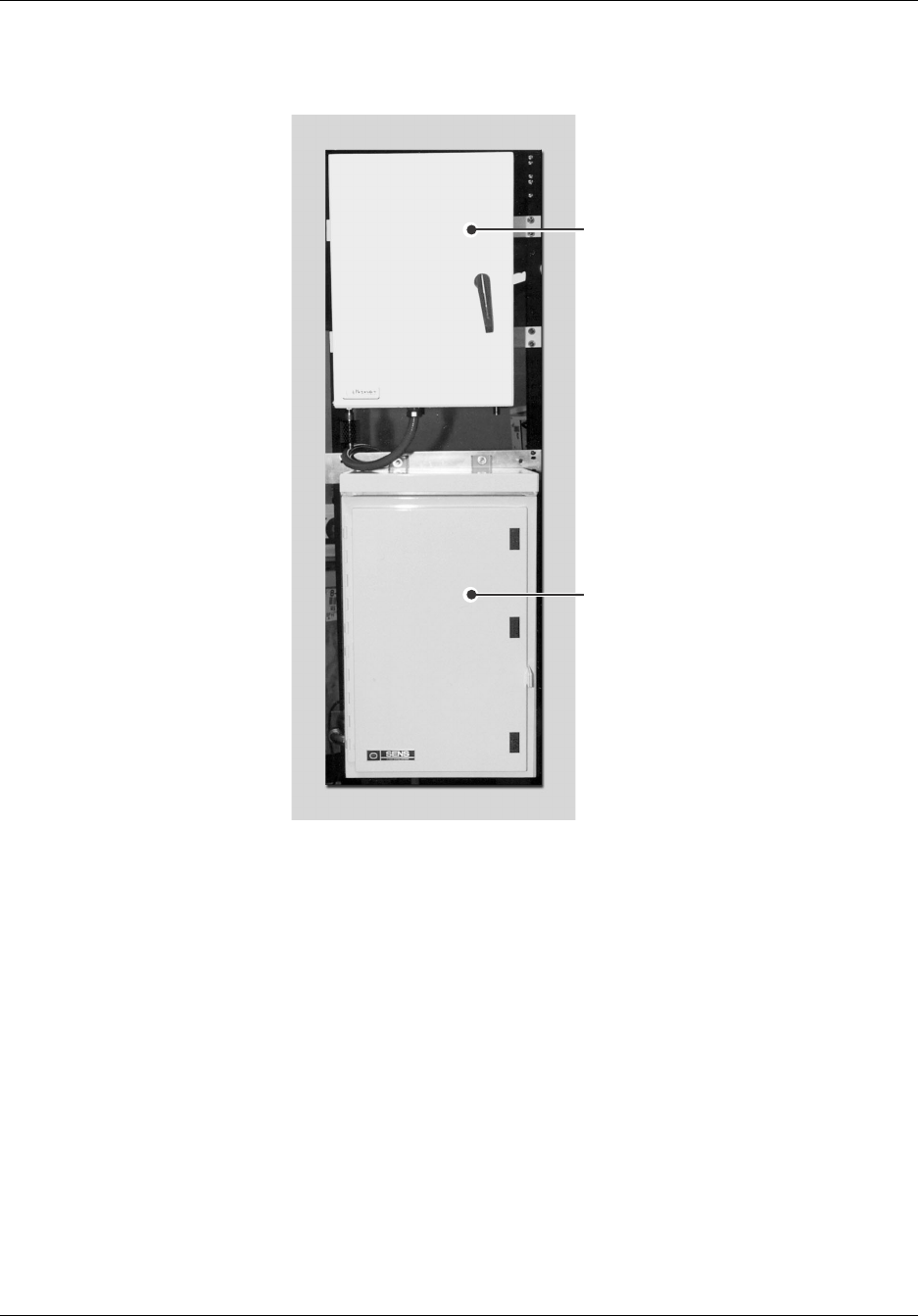
Figure 2-1 shows a typical repeater installation with a Back-Up Power System (BUPS).
NOTE: RTI Repeaters are not intended for mobile operation and should be placed in a
fixed location.
Mounting the Repeater Reference Manual
2-2 RTI Confidential 550-1300-01 Rev C
Figure 2-1 Typical Repeater Installation
RT227103
BUPS
Repeater
Reference Manual Mounting the Repeater
550-1300-01 Rev C RTI Confidential 2-3
2.1 Mounting the Repeater
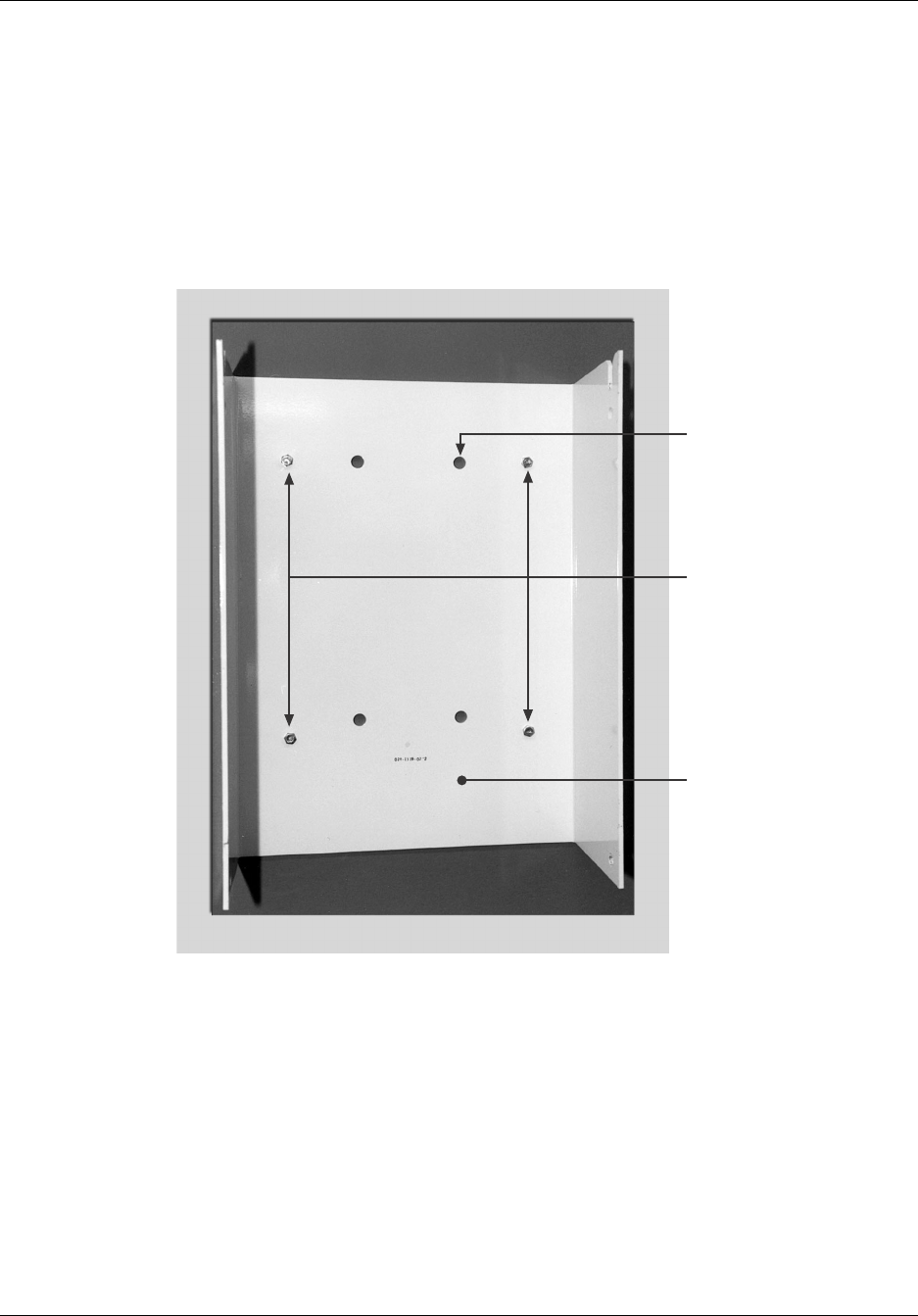
Figure 2-2 illustrates the bracket for mounting the repeater. In both the wall-mounting
and pole-mounting installation instructions that follow, this bracket is detached from the
repeater and attached to the wall or pole. The repeater is then inserted into the bracket.
Figure 2-2 Rear Mounting Bracket
Mount any antennas, antenna cabling, and BUPS equipment (if used) before mounting
and wiring the repeater.
RT199104
Mounting
Bracket
Lug Bolts
(4 positions,
user supplied)
Pole Mount Hole Pattern
(4 positions, for use
with the Pole Mounting Kit
P/N 091-0215-01)

Mounting the Repeater Reference Manual
2-4 RTI Confidential 550-1300-01 Rev C
2.1.1 Wall Mounting
Customer supplied hardware for wall-mounting a repeater includes the following:
•Four(4) lag (hexagonal-head) bolts
•Four(4) flat washers
•Four(4) split-lock washers
To mount the repeater on a wall:
1. Separate the rear mounting bracket from the repeater by removing the security bolts
and washers.
To do this, use either a ratchet or a 1/4" hex driver, and the 7/32" pin-in-socket driver
that is provided in the accessory kit.
2. Using the mounting hardware (hex-head lag bolts, split-lock washers, and flat wash-
ers), secure the bracket to a wall.
3. To set the repeater into the bracket, align the top of the repeater cabinet just above the
top of the mounting bracket so that the mounting bracket will fit inside the left and
right walls of the repeater cabinet.
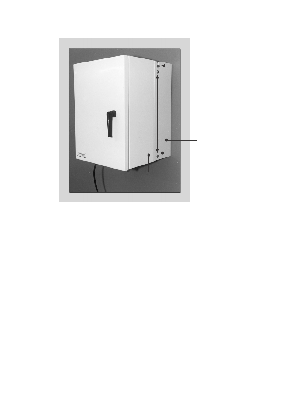
4. Slide the repeater cabinet downward so that the guide bolt (on the repeater cabinet)
slips into the guide slot (on the mounting bracket), as shown in Figure 2-3.
5. Replace the security bolts and washers that were removed in Step 1.
Reference Manual Mounting the Repeater
550-1300-01 Rev C RTI Confidential 2-5
Figure 2-3 Guide Bolt and Slot
RT199101
Guide Pins
Tamper Proof
Fasteners
Mounting Bracket
Repeater Assembly
Install Padlock for
Additional Security

Mounting the Repeater Reference Manual
2-6 RTI Confidential 550-1300-01 Rev C
2.1.2 Pole Mounting
NOTE: Two people are recommended for pole-mounting the repeater.
RTI offers optional pole-mounting equipment that you can order with the repeater.
Pole installation requires the following materials:
•Pole mounting kit (available from RTI). See Table 2-1.
•Banding kit (purchased separately; available from McMaster-Carr) for mounting
the repeater on a concrete or metal pole. See Table 2-1.
•Class A - Pole Line Hardware for bolting the Pole Mounting Bracket to a wood
pole.
•Class A - Pole Line Hardware is a telephone term. It specifies bolts and screws
that have a heavy electro-galvanized plating so they do not rust. This type of rug-
ged hardware typically is available from telephone equipment distributors such
as Graybar Electric, ALLTEL Supply, Spring-North Supply, PowerTel Supply, and
so on. The same type of hardware is also available from antenna suppliers and
from tower erector companies.
The Pole Mounting Channel is designed so that the repeater is squarely mounted on the
pole and does not wobble.
When mounting the repeater onto a concrete or metal pole, use the Banding Kit. You ordi-
narily would not drill a mounting hole through the center of a concrete pole. Similarly,
because metal poles might have cables running up the center, drilling is not recom-
mended. In both cases, banding is preferred over drilling.
However, wood telephone-type poles are easier to drill, so you can use lag screws or
through-pole bolts to fasten the pole-mounting channel.
Table 2-1 describes the Pole Mounting and Banding Kits. Because the Banding Kits
includes 100 feet of band, you do not need to purchase a separate kit with every repeater.
The banding kit is available from McMaster Carr Supply Co, Los Angeles, CA USA, tele-
phone# (562)692-5911.

Reference Manual Mounting the Repeater
550-1300-01 Rev C RTI Confidential 2-7
Table 2-1 Pole Mounting Kit (P/N 091-0215-01)
Table 2-2 Banding Kit (P/N 5653K12)
To mount the repeater to a pole:
1. Separate the rear mounting bracket from the repeater by removing the security bolts
and washers.
Use either a ratchet or a 1/4" hex driver, and the 7/32" pin-in-socket driver that is
provided in the accessory kit.
2. Using the hardware provided with the accessory kit, secure the rear mounting
bracket to the two(2) pole brackets - see Figure 2-4 and Figure 2-5.
3. Insert the four plugs provided, into the four outer holes in the rear mounting bracket.
4. Position the rear mounting bracket (the bracket that has an attached pole channel)
against the pole and hold it in place.
5. While one person holds the rear mounting bracket in place, the second person
installs the steel bands that hold the bracket against the pole.
Consult the manufacturer's instructions (included with the Banding Kit) for this pro-
cedure.
Quantity Item
1 Pole Mounting Channel
4Bolts
4Split-Lock Washers
4Flat Washers
4 Tapered Plug, .312D Hole
Quantity Item
1 Tightening-Crimping Tool
100 ft. 3/4-inch, Type 201 Stainless Steel Band
100 Stainless Steel Buckles
25 Stainless Steel Scru-Locket Buckles
1Carrying Case
Mounting the Repeater Reference Manual
2-8 RTI Confidential 550-1300-01 Rev C
Figure 2-4 Pole Mounting Hardware
6. To set the repeater into the bracket, align the top of the repeater cabinet just above the
top of the mounting bracket so that the mounting bracket will fit inside the left and
right walls of the repeater cabinet.
7. Slide the repeater cabinet downward so that the guide bolt (on the repeater cabinet)
slips into the guide slot (on the mounting bracket), as shown in Figure 2-3.
8. Replace the security bolts and washers that were removed in Step 1.
Two 7/8 dia. holes for
3/4 lag of thru-pole bolts
Pole
Mounting
Channel
4 x Plug
4 x Flat Washer
4 x Lock Washer
4 x Bolt RT130116
Reference Manual Mounting the Repeater
550-1300-01 Rev C RTI Confidential 2-9
Figure 2-5 Pole Mount - Side View
Pole
Mounting
Channel
Repeater
Mounting
Bracket
Lifting
Assist
Hole 3/4 Thru-pole
Bolts with Flat
Washers and
Locking Aero Nut
Banding
Straps
Pole or Mast
RT130117

Mounting the Repeater Reference Manual
2-10 RTI Confidential 550-1300-01 Rev C

550-1300-01 Rev C RTI Confidential 3-1
3
Connecting Primary Power to the
Repeater
3.0 Introduction
Primary power connects to the repeater through the bottom of the cabinet.
Table 3-1 shows the specifications for the input power.
Table 3-1 Input Power Specifications
CAUTION: This system requires either AC or DC power to operate. Do not connect both
AC and DC at the same time as it will damage the system.
ATTENTION: Ce système requiert une alimontation CA ou CD pour operer. Ne pas
brancher le CA et le CD simultanément leci porrait endommager le système.
NOTE: RTI recommends using a 15 Amp circuit for AC powered systems and a 25 Amp
circuit for DC powered systems.
Type Power Specification
Alternating Current 115/230 Volt AC Auto-ranging, 47 to 63 Hz
(Operating Range: 100 to 240 Volt AC)
RC-1X10 260 Watts, typical
RC-1X15 330 Watts, typical
RC-2X10 400 Watts, typical
RC-2X15 470 Watts, typical
Direct Current 24 Volt DC, -3/+6 Volts
RC-1X10 9.0 Amps, typical
RC-1X15 11.0 Amps, typical
RC-2X10 13.0 Amps, typical
RC-2X15 15.0 Amps, typical
Connecting Primary Power to the Repeater Reference Manual
3-2 RTI Confidential 550-1300-01 Rev C
3.1 AC Power Wiring
The following steps describe how to connect AC power to the repeater:
NOTE: Before wiring the repeater, verify that all input power is OFF and all circuit
breakers in the repeater are in the OFF position.
Figure 3-1 Line Entry Module - AC Wiring
1. Route AC power to the repeater using 1/2" liquid tight flexible conduit, and the
appropriate liquid tight conduit fittings. Access holes are located at the bottom of the
repeater for convenience. For indoor installations, normal 1/2" metal conduit may be
used. See Figure 3-1.
2. Wire the repeater using #14 AWG or larger stranded PVC wire. Connect the neutral
and hot leads to the Line Entry Module and the ground lead to the interior ground
lug located on the inside of the cabinet. Connect the repeater to an AC power source
using a dedicated 15 Amp fuse or circuit breaker.
NOTE: Number 14 gauge wire complies with most local and national electrical codes
because the Repeater Power Switch is also a magnetic circuit breaker which limits current
to a maximum of 15 Amps. Consult your local or national electrical safety codes for the
appropriate wire sizes.
3. Close the AC circuit breaker to turn the repeater on.
Reference Manual Connecting Primary Power to the Repeater
550-1300-01 Rev C RTI Confidential 3-3
3.2 DC Power Wiring
The following steps describe how to connect DC power the repeater:
NOTE: Before wiring the repeater, verify that all input power is OFF and all circuit
breakers in the repeater are in the OFF position.
Figure 3-2 Line Entry Module - DC Wiring
1. Route DC power to the repeater using 1/2" liquid tight flexible conduit, and the
appropriate liquid tight conduit fittings. Access holes are located at the bottom of the
repeater for convenience. For indoor installations, normal 1/2" metal conduit may be
used.
2. Wire the repeater using up to #10 AWG stranded PVC wire. Connect the positive and
negative leads to the Line Entry Module and an earth ground lead to the interior
ground lug located on the inside of the cabinet. Connect the repeater to a DC power
source using a dedicated 25 Amp fuse or circuit breaker. See Figure 3-2.
NOTE: Consult your local or national electrical safety codes for the appropriate wire siz-
ing.
3. Close the DC circuit breaker to turn the unit on.

Connecting Primary Power to the Repeater Reference Manual
3-4 RTI Confidential 550-1300-01 Rev C
3.3 Wiring an External Back-up Power Supply
A typical Back-up Power Supply (BUPS) consists of a charger/rectifier, and has 24-Volt
batteries floated across the charger/rectifier output.
Figure 3-3 shows the block diagram of a BUPS available from RTI.
•The RTI BUPS-25/80 rectifier supplies up to 25 Amperes of continuous current at
24 Volts DC.
•Two internal batteries are sized to provide 80 Amp-Hours of service without AC
power.
•The backup times for the different models are listed below:
RC19-1X10 9 Hours
RC19-1X15 7 Hours
RC19-2X10 6 Hours
RC19-2X15 5 Hours
CAUTION: Risk of explosion if battery is replaced by incorrect type.
ATTENTION: Risque d’explosion si le modèle de pile n’est pas utiliser recommandé.
For more details about the RTI BUPS, see the RTI BUPS-25/80 Operation Manual, Docu-
ment Number 550-1011-01.
Reference Manual Connecting Primary Power to the Repeater
550-1300-01 Rev C RTI Confidential 3-5
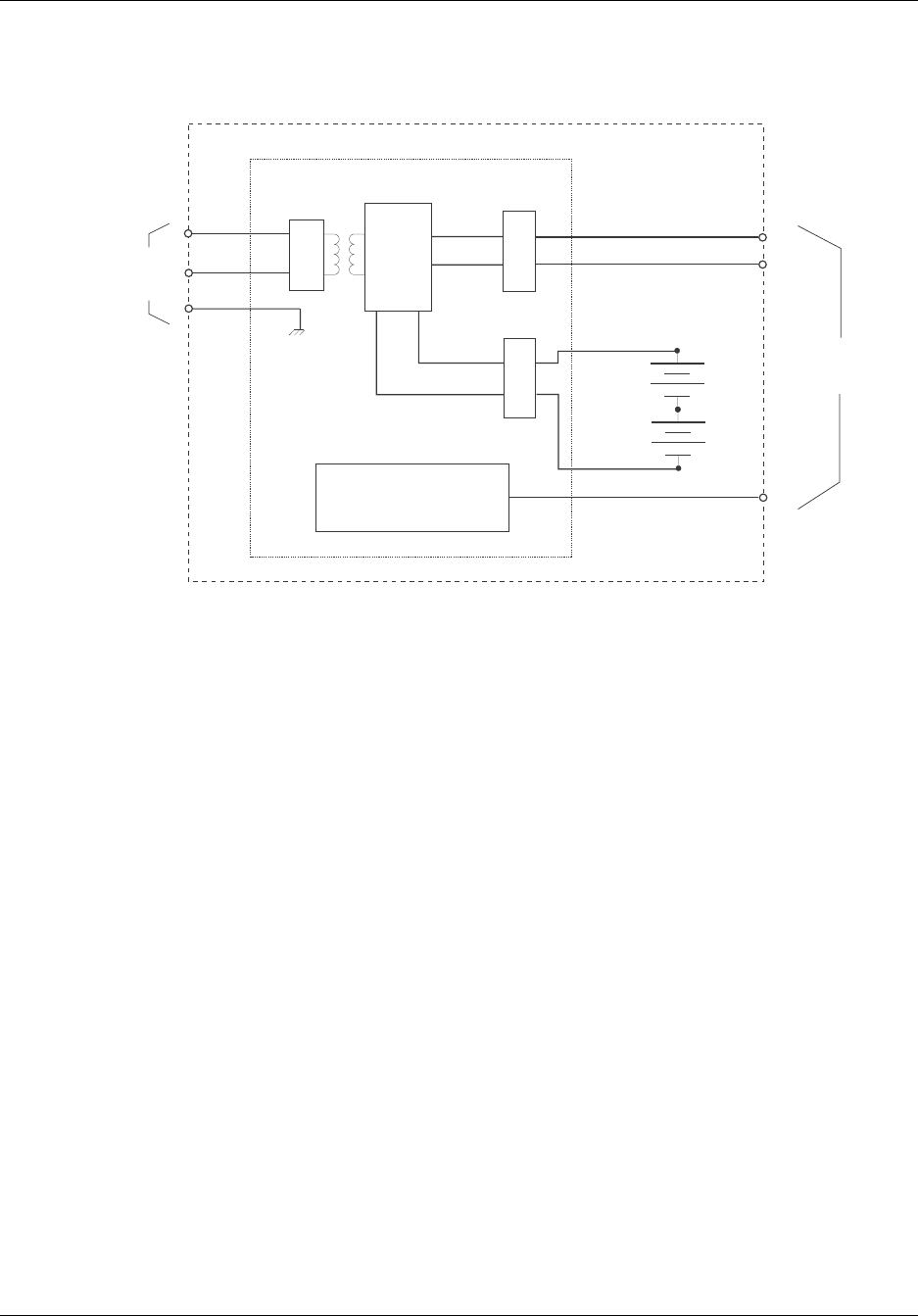
Figure 3-3 Simplified BUPS-25/80 Block Diagram, RTI P/N 250-1011-07
Rectifier / Charger
Ckt Bkr Ckt Bkr
Ckt Bkr
Two
12 Volt
Batteries
Monitors and Alarm Circuitry with
Indicators and Relay Outputs
Current
and
Voltage
Regulation
Circuit
115/230
VAC
(switchable)
To
Repeater
24
Volts
Alarms
RT116901

Connecting Primary Power to the Repeater Reference Manual
3-6 RTI Confidential 550-1300-01 Rev C
The following steps describe how to power a BUPS and connect it to a repeater:
NOTE: Before wiring the repeater, verify that all input power is OFF and all circuit
breakers in the repeater and BUPS are in the OFF position.
1. Route AC power to the BUPS using 1/2" liquid tight flexible conduit, and the appro-
priate liquid tight conduit fittings. Access holes are located at the bottom of the
repeater for convenience. For indoor installations, normal 1/2" metal conduit may be
used.
2. Wire the BUPS using #10 AWG or larger stranded PVC wire. Connect the neutral, hot
and ground leads to the rectifier front panel. Figure 3-4 shows the front panel of the
BUPS Charger-Rectifier. Connect the BUPS to an AC power source using a dedicated
15 Amp fuse or circuit breaker. Typical BUPS-25/80 input voltage and current speci-
fications are:
115 Volts AC @ 10 Amps
230 Volts AC @ 5 Amps
3. Install the two 12-volt Gel Cell batteries.
4. Use the wires provided with the BUPS to connect the batteries to the rectifier.
5. Verify the battery voltage at the BUPS Rectifier terminal block, using a multi-meter.
The multi-meter should read approximately 25 to 27 Volts.
6. Wire the BUPS to the repeater as shown Figure 3-5. The RTI BUPS-25/80 includes the
1/2" Liquidtight flexible steel conduit, the power and alarm wiring, and the neces-
sary Liquidtight conduit fittings to connect the BUPS to the repeater.
7. Close the BUPS AC Input circuit breaker.
8. Close the BUPS Charger circuit breaker.
9. Close the Battery circuit breaker.
10. Verify the voltage using the BUPS Test Terminals. The multi-meter should read
approximately 27 Volts.
11. Close the repeater DC circuit breaker.
12. Observe the Repeater load in Amps using the BUPS Load Test Terminals. Under nor-
mal conditions, the load should be approximately 9 - 15 Amps depending on the
repeater model. Reference Table 3-1
Reference Manual Connecting Primary Power to the Repeater
550-1300-01 Rev C RTI Confidential 3-7
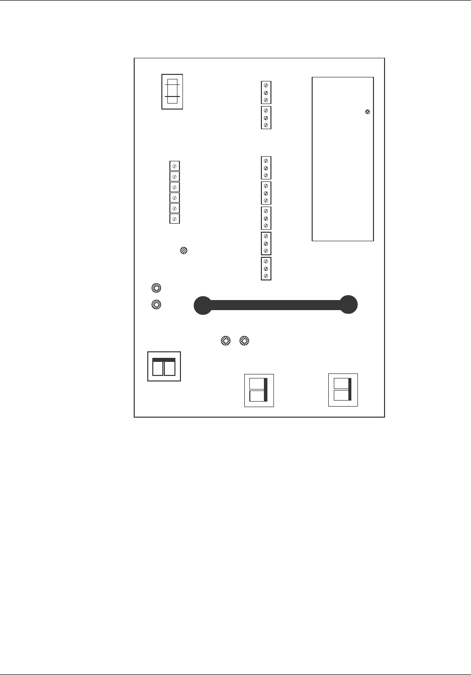
Figure 3-4 Front Panel of the BUPS-25/80 Charger-Rectifier
ON ON
ON ON
ON ON
Charger
Breakers Battery
Breakers
-+
-
+
GND
COM
OK
FAIL
COM
OK
FAIL
COM
OK
FAIL
COM
OK
FAIL
COM
OK
FAIL
COM
OK
FAIL
COM
OK
FAIL
OPTION
SUMM
HIGH
DC
VOLT
LOW
DC
VOLT
+
+
-
-
AC Input
Breakers
DC Volts DC Amps
1mV/Amp
BATT
LOAD
AC
Input CHGR
FAIL
AC
FAIL
GRD
FAIL
L
N
N/C
Input
Voltage
Select
Alarm LEDs
Option Shut Down Load Disc Float
Hi DC Low DC Boost
Chgr Fail AC Fail
RT117902
Lamp Test
Connecting Primary Power to the Repeater Reference Manual
3-8 RTI Confidential 550-1300-01 Rev C
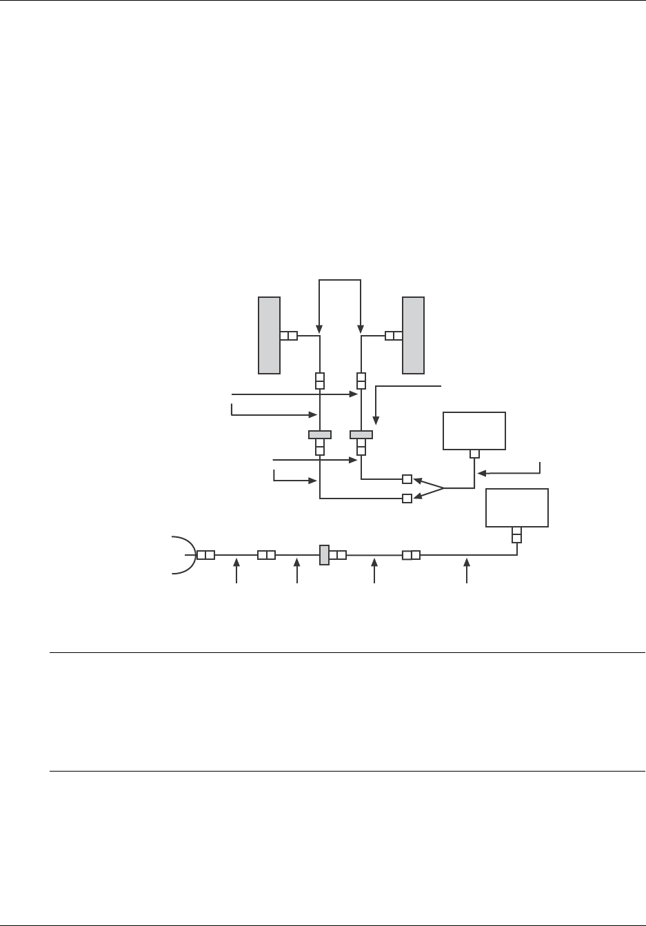
Figure 3-5 Wiring Connections from the Repeater to a BUPS-25/80
REPEATER TERMINAL BLOCK
IN/OUT
Tie back Leads if door
alarm is not available,
and disable Ext.
Tamper Alarm
BUPS 25/80
CHARGER TERMINAL
BLOCK
BLK
RED
COM
OK
OK
COM
FAIL
FAIL
FAIL
FAIL
COM
COM
COM
OK
OK
OK
BLK
BLK
BLK
SUMM
OPTION
HIGH
DC
VOLT
LOW
DC
VOLT
FAIL
CHGR
AC
GRN
WHT
BLK
BLU
YEL
BRN
BLK
FAIL
FAIL
FAIL
COM
OK
COM
OK
FAIL
FAIL
GRD
Door - future
BATT
LOAD
Two
Batteries
+
+
-
-
L
N
AC
INPUT
GRD
LUG
117/220 VAC
Neutral
Ground
6 1/2 Liquidtight Flex Conduit
1 - Digital Output 1
2 - Digital Output 2
3 - DC Voltage Input (Monitor)
4 - Digital Input 1
5 - Digital Input 2
6 - Digital Input 3
7 - Digital Input 4
1 - External Tamper Alarm (Secondary Door Alarm)
2 - BUPS Tamper Input (External Input Alarm)
3 - BUPS AC Fail Input (External Alarm)
4 - BUPS Low Battery Voltage Input (External Input Alarm)
5 - BUPS High Battery Voltage Input (External Input Alarm)
6 - BUPS Charger Fail Input (External Input Alarm)
7 - BUPS Summary Normally Closed (External Input Alarm)
8 - BUPS Summary Com (Protected Ground)
8 Ft. Belden 8743m 22 AWG Solid, 6 Twisted Pairs, PVC Insulation, 150V
80 deg., Jacket cut back 4, conductor ends stripped back 1/4, Grd. Lug
and terminated in single yellow #10 spade terminal, (Part of RTI Part No.
187-0188-01, Power & Alarm Cable Assembly, included with the RTI
BUPS-25/80 product).
Legend:
#22 AWG
#10 AWG
#10 AWG Spade Term.
#6 AWG Spade Term.
#10-12 AWG Pin Term.
Stripped-back and Tinned
DC
INPUT
+
-
Chassis Ground and
-24 Volts DC are
common in repeater
8 Ft. Royal W0781, 10 AWG, Stranded, PVC Insulation, 300V -60 C, repeater ends
stripped back 0.3 and tinned, BUPS ends stripped-back and terminated with #10 Spade
Term. (part of RTI P/N 187-0188-01, BUPS Power & Alarm Cable Assembly, included
with the RTI BUPS-25/80 product).
RT130165
Repeater to BUPS-25/80 Wiring
BUPS
GRD
LUG

Reference Manual Connecting Primary Power to the Repeater
550-1300-01 Rev C RTI Confidential 3-9
3.4 Grounding
Connecting input power to the repeater includes installing the standard electrical service
grounds. However, you must also make sure that the repeater and any associated equip-
ment is properly grounded to a water pipe or earth ground. For more information about
grounding repeaters, consult the RTI Application Note titled Installation Standards for
Ground Requirements, Document Number 650-0002-01, Rev. 2.
The repeater cabinet includes one external ground lug as shown in Figure 3-6.
1. Connect number 6 AWG minimum solid copper wire to the repeater ground lug.
2. Carefully dress the wire along cabinet, and the mounting surface, to the Repeater
Grounding System or the Ground Rod.
NOTE: When dressing the ground wire, and forming it around corners, avoid making
sharp bends in the wire. Use a generous radius for each wire bend.
3. Connect the ground wire to a suitable earth ground - for example, to a copper
ground rod, copper pipe, grounded steel building frame, or similar ground point. -
see Figure 3-7
4. Ground all other cabinets, enclosures, antennas, and coaxial cables used for installa-
tion, to reduce any damage from a lightning strike or power surge.
Figure 3-6 Location of External Ground Lug
RT199105
Exterior Ground
Attachment Point
Copper Ground
(6 AWG min)

Connecting Primary Power to the Repeater Reference Manual
3-10 RTI Confidential 550-1300-01 Rev C
Figure 3-7 Typical System Ground
System
Standard Ground Rod,
1/2 - inch diameter
8 feet minimum
(soil type is a factor in
grounding depth
requirements)
RT130118

550-1300-01 Rev C RTI Confidential 4-1
4
Installing Antennas
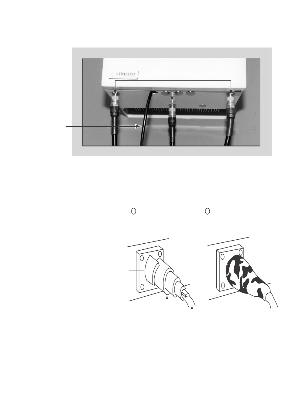
4.0 Moisture Protection for Antenna Connections
NOTE: This should be done after the repeater has been fully configured, functionally set-
up and further work is not required.
The bottom of the repeater cabinet has N-type (7/16" DIN is optional) connections for
donor and subscriber antennas, as shown in Figure 4-1. RTI recommends that before
installing the repeater and connecting it to the antennas, you apply a tar-like Vapor Wrap,
to seal these antenna connections against rain or other water sources (See Figure 4-2).
1. Wrap the threads of the N-type antenna connectors, with electrical tape. This protects
the connector threads from the sticky Vapor Wrap substance.
2. Thoroughly coat the outside of the electrical tape with the Vapor Wrap putty.
3. Wrap another layer of electrical tape over the Vapor Wrap to seal the Vapor Wrap
into place.
After you complete this procedure for all N-type antenna connectors, moisture should
not adversely affect the connections between the repeater cabinet, and the donor and sub-
scriber antennas.
Installing Antennas Reference Manual
4-2 RTI Confidential 550-1300-01 Rev C
Figure 4-1 N-Type Antenna Connectors, Looking Up From the Bottom of the Repeater Cabinet
Figure 4-2 RF Connector Cable with Vapor Wrap
RT199103
External
Power
RF Connections to Repeater Assembly
RT206102
Coax
Seal Material
Connector
The Sealing Material will
bond to the connector and
Coax Cable providing a
moisture barrier
2
Wrap Material around the
connector and onto the
Coax as shown
1

Reference Manual Installing Antennas
550-1300-01 Rev C RTI Confidential 4-3
4.1 Antenna Configurations
RTI repeaters can use any one of following antenna configurations:
•Donor antenna, and one dual polarized subscriber antenna (see Figure 4-3)
•Donor antenna, and two vertically polarized subscriber antennas (see Figure 4-4)
•Donor antenna, and two dual polarized subscriber antennas-back beam configu-
ration (see Figure 4-5)
•Donor antenna, and one vertically polarized subscriber antenna (see Figure 4-6)
•Donor antenna, and two dual polarized subscriber antennas-dual direction con-
figuration (see figure Figure 4-7)
NOTE: When included in a CDMA network, an RTI repeater can use a back-beam
antenna, to transmit energy from the repeater, back towards the donor base station. A
back-beam antenna increases the allowable distance between the donor BTS and the
repeater site.
Installing Antennas Reference Manual
4-4 RTI Confidential 550-1300-01 Rev C
Figure 4-3 Dual Polarized Subscriber Antenna Configuration
To Lightning Arrestor Assembly
Feeder Cable
(Donor)
Top Jumper
Cable (Donor)
Donor
Antenna
Feeder Cable
(Tx/Main Receive)
Subscriber
Antenna
(Dual Polarized)
18 - 20
Top Jumper Cable
(Tx2/Rx Diversity)
Feeder Cable
(Diversity Receive)
RT295904
-45º Port
+45º Port
Top Jumper Cable
(Tx1/Rx Main Receive)
Reference Manual Installing Antennas
550-1300-01 Rev C RTI Confidential 4-5
Figure 4-4 Two Vertically Polarized Subscriber Antennas
To Lightning Arrestor Assembly
Feeder Cable
(Donor)
Top Jumper
Cable (Donor)
Donor
Antenna
Feeder Cable
(Tx1/Rx Main Receive)
Top Jumper Cable
(Tx/Main Receive)
Tx/Rx
Main Antenna
Vertically
Polarized
Antennas
Rx Diversity
Antenna
18 - 20
Top Jumper Cable
(Tx2/Rx Diversity)
Feeder Cable
(Diversity Receive)
RT295901
Installing Antennas Reference Manual
4-6 RTI Confidential 550-1300-01 Rev C
Figure 4-5 Back Beam Antenna Configuration
To Lightning Arrestor Assembly
Feeder Cable
(Donor)
Top Jumper
Cable (Donor)
Donor
Antenna
Feeder Cable
(Tx1/Rx Main Receive)
Back-Beam
Antenna
(Dual Polarized)
Main-Beam
Antenna
(Dual Polarized)
18 - 20
Top Jumper Cable
(Main Beam
Diversity Receive)
Feeder Cable
(Diversity Receive)
RT295902
ca. 4ft.
-45º Port
+45º Port
-45º Port
+45º Port
Top Jumper Cable
(Main-Beam Tx
/Main Receive)
Direct Port
Coupled Port
Coupler
Coupler
Direct Port
Coupled Port
Top Jumper Cable
(Back Beam Tx Main Receive)
Top Jumper Cable
(Back-Beam Diversity Receive)
Reference Manual Installing Antennas
550-1300-01 Rev C RTI Confidential 4-7
Figure 4-6 Non-Diversity Antenna Configuration
To Lightning Arrestor Assembly
Feeder Cable
(Donor)
Top Jumper
Cable (Donor)
Donor
Antenna
Feeder Cable
(Tx1/Rx Main Receive)
Top Jumper Cable
(Tx/Main Receive)
Tx/Rx
Main Antenna
Vertically
Polarized
Antenna
RT199106
Installing Antennas Reference Manual
4-8 RTI Confidential 550-1300-01 Rev C
Figure 4-7 Dual Direction Antenna Configuration
To Lightning Arrestor Assembly
Feeder Cable
(Donor)
Top Jumper
Cable (Donor)
Donor
Antenna
Direction 1
Antenna
(Dual Polarized)
Direction 2
Antenna
(Dual Polarized)
18 - 20
Top Jumper Cable
(Rx Div 1)
Feeder Cable
(Rx Div 1)
RT295903
ca. 4ft.
-45º Port
+45º Port
-45º Port
+45º Port
Top Jumper Cable
(Rx Div 2)
Top Jumper Cable
(Tx 1/Rx Main 1)
Feeder Cable
(Tx 2/Rx Main 2)
Top Jumper Cable
(Tx 2/Rx Main 2)
Feeder Cable
(Rx Div 2)
Feeder Cable
(Tx 1/Rx Main 1)

Reference Manual Installing Antennas
550-1300-01 Rev C RTI Confidential 4-9
4.2 Antenna Cables
A repeater uses the same type of RF cabling as a base station does. Usually, the top and
bottom jumper cables are made from flexible, 1/2" air dielectric coaxial cable, and the
feeder lines are made from 7/8" to 1-5/8" foam dielectric coaxial cable.
Diversity repeater configurations (see Figure 4-3, Figure 4-4, and Figure 4-5) require
three(3) RF lines:
•One for the donor antenna
•One for the main subscriber antenna
•One for the diversity subscriber antenna
4.3 Lightning Protection
RTI strongly recommends installing lightning arrestors on all feeder cables to the
repeater. A direct lightning strike can damage any electronic equipment. Damage
resulting from a lightning strike is not covered under the RTI manufacturer's warranty,
whether or not you use lightning arrestors. However, using lightning arrestors can min-
imize the risk of damaging a repeater, and of losing cellular phone coverage, during light-
ning storms.
Use lightning arrestors that attach directly to the large-diameter feeder cables, and not to
the repeater itself. Do not use screw-on lightning arrestors, because they attach to the
repeater's antenna terminals. Shunt the lightning to the ground, as far away from the
repeater as possible.
For additional lightning protection of the power and telecommunication lines, please
contact RTI.
Installing Antennas Reference Manual
4-10 RTI Confidential 550-1300-01 Rev C
Figure 4-8 shows a typical repeater installation, using coaxial lightning arrestors on the
feeder lines. For safety and operational dependability, RTI also recommends attaching all
antennas to the repeater site's single point ground.
Figure 4-8 Lightning Arrestor, Grounding, and Repeater RF Cabling
Transcient
Surge/Lightning
Protection
Repeater Site
Earth Ground
(Minimum 6 AWG
Copper Wire)
Repeater
Cabinet
Lightning Arresters
(Customer supplied)
To Service
Interconnection
(Power, Phone)
RT204102

Reference Manual Installing Antennas
550-1300-01 Rev C RTI Confidential 4-11
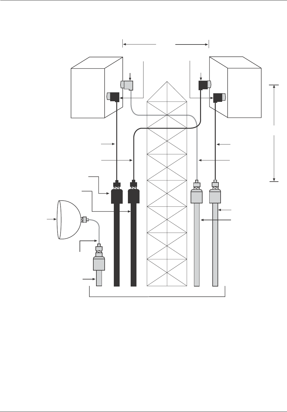
4.4 Back-Beam Antennas and Directional Couplers
A back-beam antenna transmits a portion of the repeater's power back toward the donor
base station (BTS). This technique is helpful on long rural routes, where two repeaters are
cascaded. In suburban or rural areas, this type of antenna can provide additional signal
capability, in the area between the donor BTS and the repeater site.
As shown in Figure 4-5, power from the repeater is applied to a directional coupler (or
power divider), which divides the power proportionately to both the main-beam and
back-beam antennas. These couplers are available in several power division ratios:
•50/50
•60/40
•75/25
•80/20
•90/10
These ratios represent the percentage of total power that the repeater channels either to
the direct port (the higher number) or the coupled port (the lower number). For example,
if the repeater uses a 75/25 coupler, the repeater sends 75% of its power to the main-beam
subscriber antenna, and the remaining 25% to the back-beam antenna.
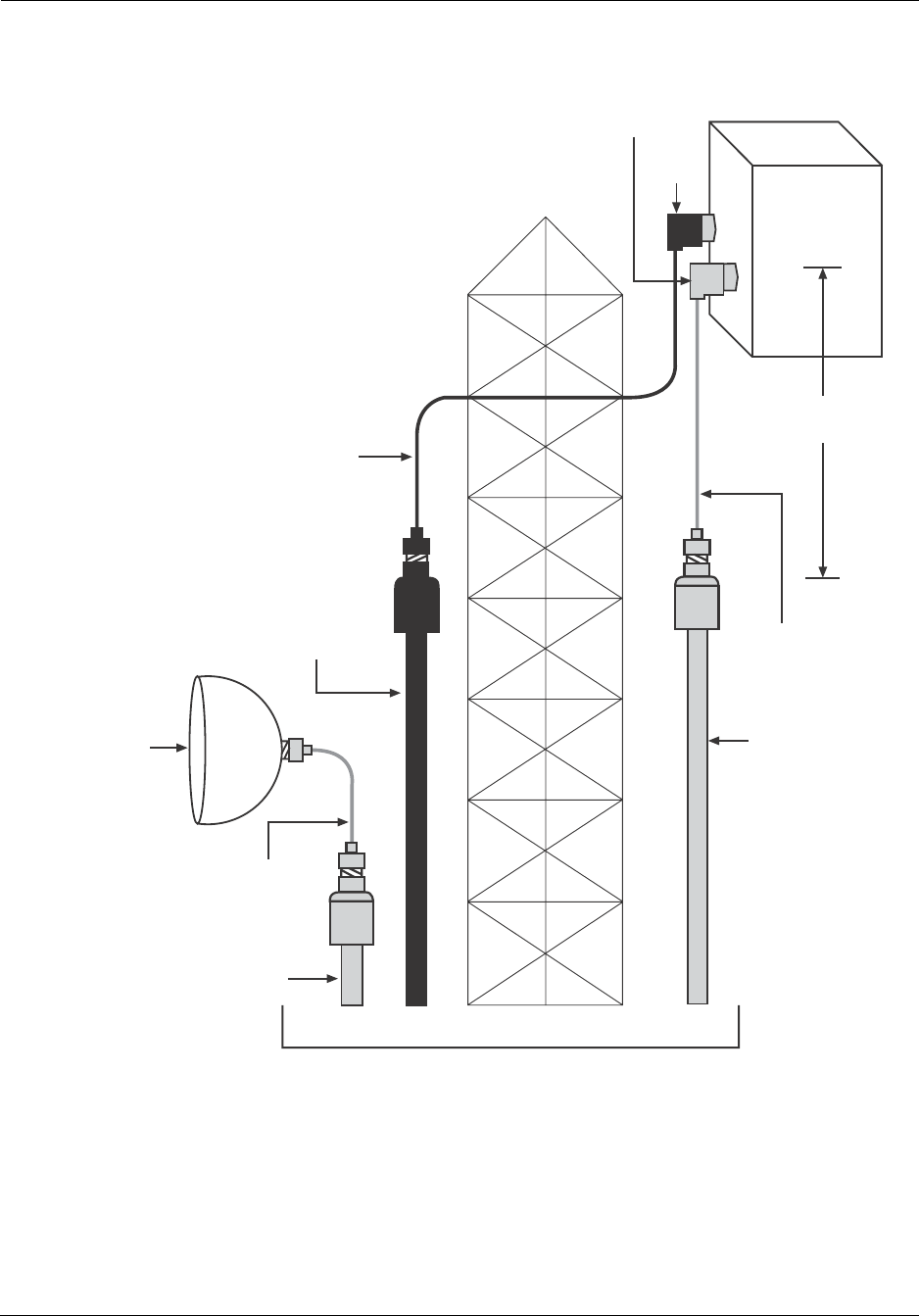
4.5 Measuring Antenna Isolation
Measure the actual isolation between the antennas, to ensure that the donor (base station)
antenna is sufficiently isolated from the subscriber (mobile) antenna. See Figure 4-9 and
Figure 4-10.
WARNING: This is a crucial step in all repeater installations.
If the isolation is not sufficient, the repeater might oscillate, or it might operate with less
gain (signal amplification). In the first case, the repeater can introduce spurious emissions
into the network. The second case, reduces the range of the repeater's coverage area.
Installing Antennas Reference Manual
4-12 RTI Confidential 550-1300-01 Rev C
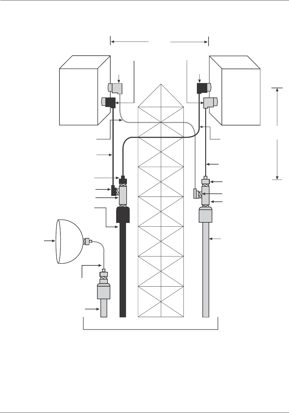
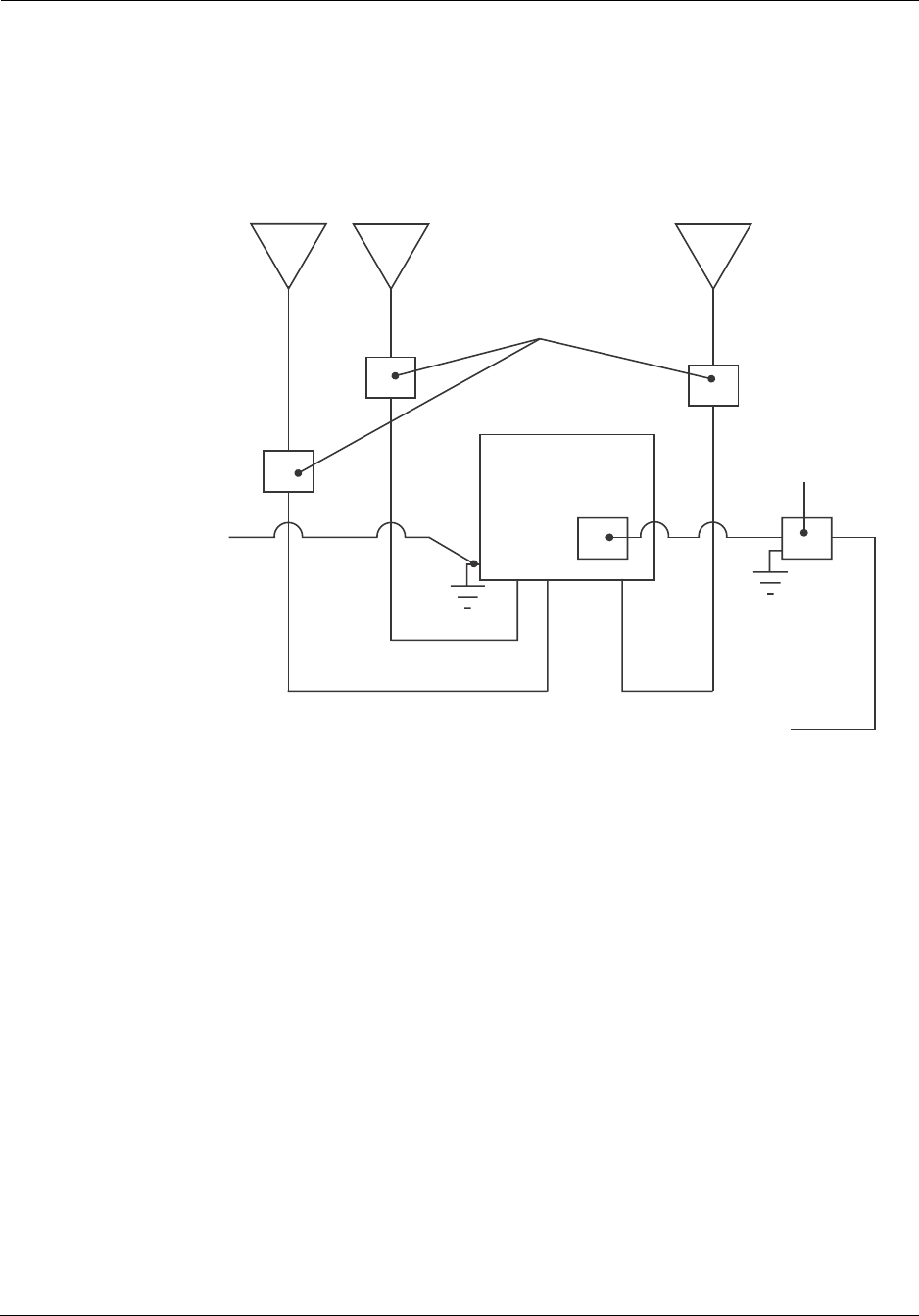
Figure 4-9 Equipment Setup for Measuring Antenna Isolation
Measuring antenna isolation requires a signal generator and a spectrum analyzer. The
generator transmits a signal from the donor antenna, and the spectrum analyzer mea-
sures the same signal as the subscriber antenna receives it. Figure 4-9 shows the equip-
ment set-up for each antenna configuration.
Dual-polarized Back-beam
Subscriber Antenna
Dual-polarized
Subscriber antenna
Dual-polarized Main-beam
Subscriber Antenna
B: Full Reveive Diversity
with Main and Back-Beam Subscriber Antennas
A: Full Receive Diversity
with Main-Beam Subscribe Antenna Only
Vertically Polarized
Subscriber antenna
Diversity Subscriber
Antenna
Main Rx/Tx
Subscriber Antenna
Spectrum
Analyzer
Signal
Generator
Donor
Antenna
Vertical
Polarization
Spectrum
Analyzer
Signal
Generator
Donor
Antenna
Vertical
Polarization
C: Non-Diversity Receive
with Single Vertically Polarized Subscriber Antenna
D: Full Receive Diversity
with Two Vertically Polarized Subscriber Antennas
Spectrum
Analyzer
Signal
Generator
Donor
Antenna
Vertical
Polarization
Spectrum
Analyzer
Signal
Generator
Donor
Antenna
Vertical
Polarization
AB
- 45º Port
+ 45º Port
- 45º Port
+ 45º Port
RT130108
Reference Manual Installing Antennas
550-1300-01 Rev C RTI Confidential 4-13
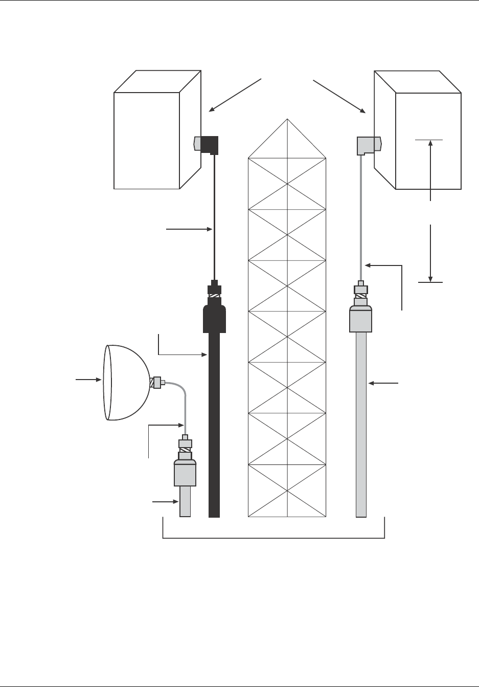
Figure 4-9 shows four simplified setups. They show only the overall configuration for
measuring antenna isolation. Isolation must take into account all cables that will be
attached when the repeater is in operation. You must measure isolation with all jumpers
and feeder lines in place. The only other cables present, that are not part of the actual iso-
lation measurement, should be the one from the signal generator, and the one to the spec-
trum analyzer. Figure 4-10 shows all cables and equipment in place for measuring actual
antenna isolation. Isolation should be measured as close as possible to the carrier fre-
quency but not in the carrier itself.
Figure 4-10 Antenna Isolation Measurement - Equipment Configuration
NOTE: If the repeater uses a back-beam antenna, you must measure antenna isolation
from both ports of both antennas (four measurements). If the repeater uses only one
antenna, only two isolation measurements are needed: one from the left port, and one
from the right port, of the subscriber antenna.
In all cases, measure antenna isolation with all cables, connectors, and lightning arrestors
in place. Record all measurements for future reference.
The equation for antenna isolation is
ISO = PGEN - LC-GEN + LC-SA - PSA
Top Jumper
Cables
Back-Beam
Antenna
Main-Beam
Antenna
Feeder
Cables
Lightning Arrestors
Bottom Jumper
Cables
Spectrum
Analyzer
Signal
Generator
Donor Antenna
Top
Jumper
Cable
Feeder
Cable
Bottom
Jumper
Cable
LC-SA
RT130109
LC-GEN

Installing Antennas Reference Manual
4-14 RTI Confidential 550-1300-01 Rev C
Where:
Where:
NOTE: A signal level of -88 dBm is stronger than a level of -90 dBm.
In this example, the usable antenna isolation is 88 dB.
ISO = Isolation in dB between the antennas
PGEN = Output level of the signal generator (dBm)
LC-GEN = Loss of the signal generator cable (dB)
LC-SA = Loss of the spectrum analyzer cable
PSA = Power indicated on the spectrum analyzer (dBm)
This equation holds true for one donor antenna, and for one vertically-polarized sub-
scriber antenna. For a dual-polarized antenna, the equation becomes:
ISO = PGEN - LC-GEN + LC-SA - MAX(PSA(L), PSA(R))
PSA(L) = Spectrum analyzer level measured on the left antenna port.
PSA(R) = Spectrum analyzer level measured on the right antenna port.
The stronger of the two readings represents the actual isolation available. For example:
PGEN = 0 dBm
LC-GEN = 1.0 dB
LC-SA = 1.0 dB
PSA(L) = -90 dBm
PSA(R) = -88 dBm
ISO = 0 - MAX(-90 or -88) = 88 dB

Reference Manual Installing Antennas
550-1300-01 Rev C RTI Confidential 4-15
4.6 Sweeping Antenna Cables
RTI recommends sweeping all RF cables for the repeater, using a network analyzer or a
time-domain reflectometer. This procedure is similar to the sweeping required for a nor-
mal base station. At a minimum, record the following data, for each cable or cable assem-
bly:
•Return Loss (dB): the ratio of power transmitted to, versus reflected from, the
cable.
•Voltage Standing Wave Ratio (VSWR): a factor in measuring the cable's imped-
ance.
•Insertion Loss (dB): the ratio of power delivered with the cable, versus without
the cable.
•Distance (in feet or meters) from one end of the cable, to a detected fault.
CAUTION: If the sweep finds any faults, correct them before placing the repeater into
service.

Installing Antennas Reference Manual
4-16 RTI Confidential 550-1300-01 Rev C

550-1300-01 Rev C RTI Confidential 5-1
5
Configuring the Repeater
5.0 RepeaterNet Craft Software
The RepeaterNet Craft Software provides configuration management and alarm monitor-
ing capabilities for individual repeaters from RTI. It also dynamically manages repeater
maintenance sessions in real time through one of the following connections:
•Direct Connection - A laptop computer with a direct connection to the repeaters -
a technician can visit repeater sites and connect to a repeater directly, using the
serial port on the laptop.
•Remote Connection (optional) - A laptop or desktop computer with a modem
connection to the repeater - a technician can use the modem to connect to a
repeater, without visiting the physical repeater site.
The Craft software can operate under either Windows 95, 98, ME, Windows NT4, or Win-
dows 2000. The Craft user interface varies, depending on the model of repeater that the
software is configured for monitoring.
5.1 Minimum System Requirements
Craft system requirements include:
•Pentium 120 MHz, running Windows 95, 98, ME, Windows NT4, or Windows
2000, with 32 Mb of memory
•If you are using the Craft system with Windows 95, you must use the Microsoft
Service Pack 1 Update (Version 4.00.950 A) or later releases.
•If you are using the Craft system with WindowsNT, you must use the Microsoft
Service Pack 3 Update or later.
•Approximately 10 Mb of free disk space
•Modem (if a modem connects the laptop to the repeater)
NOTE: RTI repeaters are compatible with Rockwell Chip Set certified for modems oper-
ating at 56k or below. US Robotics modems are not supported.

Configuring the Repeater Reference Manual
5-2 RTI Confidential 550-1300-01 Rev C
If the PC or laptop uses a fax program, such as Microsoft Fax, make sure that the Auto
Answer feature is disabled. See Appendix B, Troubleshooting (Problem 7) for how to dis-
able Auto Answer for Microsoft Fax.
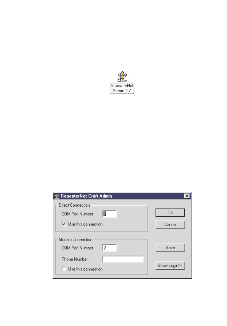
5.2 Installation Procedure
The Craft software is distributed on a CD-rom. To install this software, use the following
procedure.
1. Insert CD into the rom drive.
If auto run is enabled, program will self start.
Figure 5-1 Startup Screen
2. Click Install Craft 2.7.
Accept defaults.
Upon completion, you will have shortcuts to Craft Administrator and Craft Software on
the desktop. See Figure 5-2.
RT205101
Reference Manual Configuring the Repeater
550-1300-01 Rev C RTI Confidential 5-3
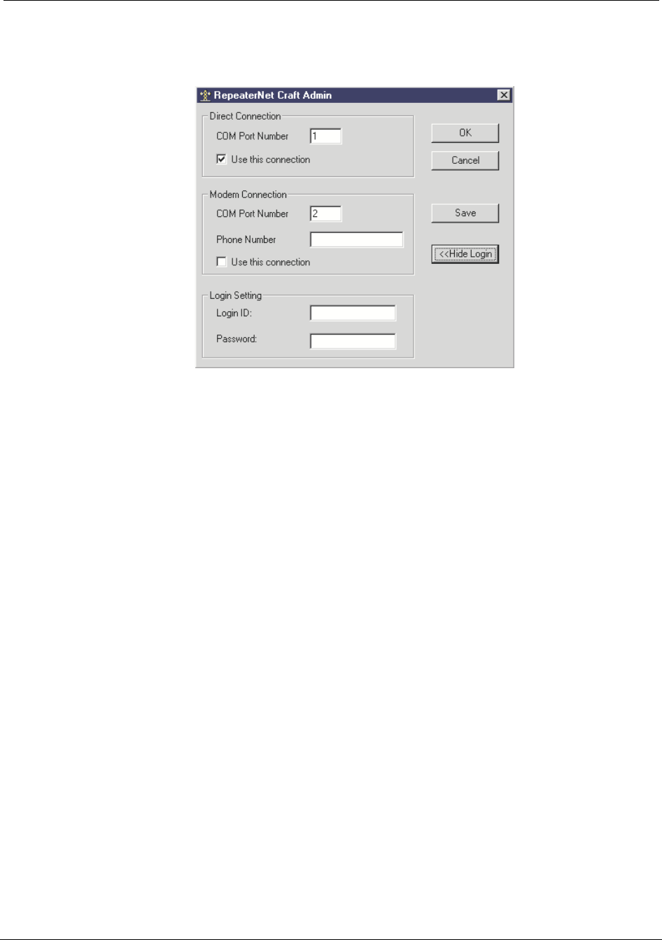
5.3 Configuring the Repeater Connection
You must use Craft Admin to configure the connection to the repeater before you can
access the Craft software.
Double Click on the RepeaterNet Admin icon from the desktop. See Figure 5-2.
Figure 5-2 Starting the RepeaterNet Administrator
When you invoke the Administrator, RepeaterNet displays the window shown in
Figure 5-3.
You can save both Direct and Dial-Out (Modem) configurations, but you must assign a
unique COM Port Number to each. Also, you can check Use this connection for only one
of the configurations. The Craft software uses the selected connection to connect to the
repeater.
You can also access and save the appropriate Craft login password by clicking on the
Show Login button. (See Figure 5-4).
Figure 5-3 RepeaterNet Admin
RT330105
RT222121
Configuring the Repeater Reference Manual
5-4 RTI Confidential 550-1300-01 Rev C
Figure 5-4 RepeaterNet Admin, Login Setting shown
RT221111

Reference Manual Configuring the Repeater
550-1300-01 Rev C RTI Confidential 5-5
For example, you might do the following:
1. Assign the connection type as Direct through an available port.
2. Check the Use this connection box to make this the default configuration.
3. Click on the Save button.
Next, you can save a Modem configuration to another Com port, such as Com Port 2:
1. Assign a Com Port Number that corresponds to the Com port assigned to the PC’s
modem.
2. Check the Use this connection box to make this the default configuration.
3. Click on the Save button.
4. Click on OK to exit RepeaterNet Admin.

Configuring the Repeater Reference Manual
5-6 RTI Confidential 550-1300-01 Rev C
5.4 Starting Craft
Double-click on the Craft icon.
The window in Figure 5-5 displays.
Craft connects to the repeater and displays the Craft Main Control screen for the repeater
as shown in Figure 5-6.
NOTE: The defaul login ID and password have been left blank. See section 5.14.2, Sys-
tem Menu - Craft, for information on changing these values.
Figure 5-5 RepetaerNet Craft Start-up Window
RT330104
RT131103
Reference Manual Configuring the Repeater
550-1300-01 Rev C RTI Confidential 5-7
5.5 Craft Main Control Screen
The Craft Main Control screen provides access to all monitor and control functions of the
Network Repeater (NR).
The Craft main control screen will appear when you launch Craft and it will retrieve the
alarms and properties from your repeater.
Main Control screen icons (shown in Figure 5-6) provide access to both subsystem status
screens and report alarms. Some icons may not appear for various hardware configura-
tion.
The Craft main control screen is used to report status from the repeater sub systems.
NOTE: This can take several minutes depending on the connection speed.
Figure 5-6 Craft Main Control Screen
Forward Front End
Channel 1 Forward
Channel Select Filter
Channel 2 Forward
Channel Select Filter
Channel 1 Reverse
Power Amplifier
Channel 2 Reverse
Power Amplifier
Alarm Control Unit
Remote
Monitoring
Power Supply Back-up
Power Supply
(BUPS)
Connection Indicator
(green=connected,
red=not connected)
Channel 2 Reverse
Channel Select Filter
Channel 1 Reverse
Channel Select Filter
Reverse Front End
Channel 1 Forward
Power Amplifier
Channel 2 Forward
Power Amplifier
RT222122

Configuring the Repeater Reference Manual
5-8 RTI Confidential 550-1300-01 Rev C
5.6 Status Reporting
After configuring the repeater, you can use the subsystem Status screens to monitor and
control repeater system functions. For example, when a repeater alarm triggers, the
appropriate subsystem icon for the type of alarm changes appearance, and starts blink-
ing.
1. Click on the subsystem icon for the type of alarm that triggered.
The appropriate status screen opens. The icon stops blinking and the audible alarm
stops. This acknowledges that you are aware of the alarm condition. However, the
icon remains the color of the alarm condition.
2. Fix the problem that triggered the alarm.
After you clear the alarm condition the display of the icon reverts to normal.
The display of the Forward PA and Reverse PA icons indicate the operational status of the
Power Amplifiers. If a PA is Off, a circle with a slash is displayed over the associated icon.
If a subsystem is not installed in the repeater, Craft displays that subsystem as disabled.
For example, if a repeater does not have the remote monitoring option installed, the
remote monitor icon is light gray.
RT228101

Reference Manual Configuring the Repeater
550-1300-01 Rev C RTI Confidential 5-9
5.6.1 Alarm Status Reporting on the Main Control Screen
RepeaterNet uses a color system to report subsystem alarm status on the Main Control
screen. Table 5-1 shows the meanings of the colors, and of any corresponding color-inde-
pendent icons.
Table 5-1 Alarm Icons
When an alarm is triggered, the icon color of the affected subsystem changes, from green
(normal), to the color of the alarm definition, and the icon blinks.
RepeaterNet also offers two optional alarm features:
The Color Independent Icons feature is provided for operators who are unable to distin-
guish color.
If an individual subsystem triggers more than one alarm, the Main Control Screen reports
the higher-severity alarm, in both the color and color-independent icons.
For example, if both a major and a minor Reverse PA alarm trigger, a yellow subsystem
icon is reported. If you clear the major alarm while the minor alarm remains active, a blue
subsystem icon is reported.
When a subsystem alarm triggers, click the icon (to open the status screen). This action
terminates the icon blinking feature, and silences the audible alarm. However, icon color
continues to report, and a color-independent icon (if applicable) continues to display
until you clear the condition that triggered the alarm.
Subsystem Alarm Statue Icon Color Color Independent Icon Action
Normal - No Alarm Green N/A N/A
Critical Alarm Red X through icon Call Out
Major Alarm Yellow Back slash through icon Call Out
Minor Alarm Blue Dotted line slash through
icon
Call Out
Event White None None
Disabled Dark Gray* N/A None
System Not Available Light Gray N/A N/A
* If all alarms in a subsystem are disabled or set to event severity, the icon color is dark gray.
Configuring the Repeater Reference Manual
5-10 RTI Confidential 550-1300-01 Rev C
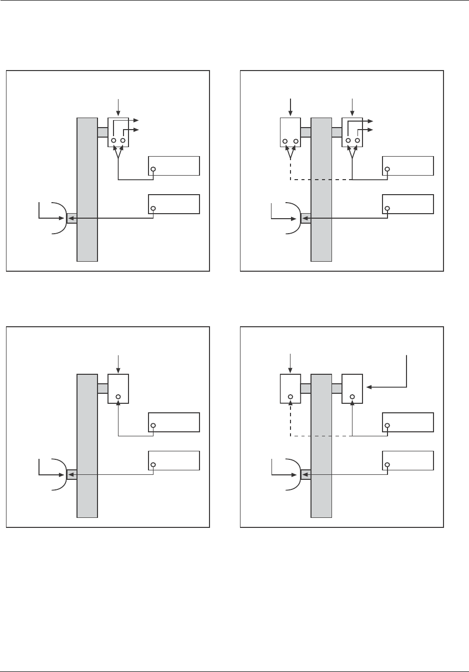
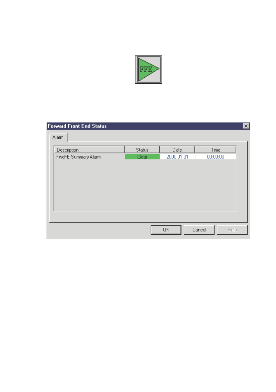
Forward Front End (FFE) Status Reporting
By clicking on the Forward Front End (FFE) icon you will bring up the FFE Alarm Status
display shown in Figure 5-7:
Figure 5-7 Forward Front End Status Window
This display shows the status of the following alarms:
FwdFE Summary Alarm - This alarm activates when the forward front end is drawing
either too much or too little current.
RT222123
RT221103
Reference Manual Configuring the Repeater
550-1300-01 Rev C RTI Confidential 5-11
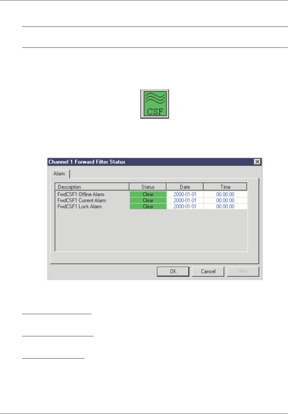
Forward Channel Select Filter (CSF) Channel 1 and 2 Status Reporting
NOTE: The alarm status and monitoring points are the same for both Forward CSF icons
with the exception of the labeling of channel 1 versus channel 2.
By clicking on the Forward Channel Select Filter (CSF) icon you will bring up the CSF
Alarm Status display shown in Figure 5-8:
Figure 5-8 Forward Channel Select Filter (CSF) Status
This display shows the status of the following alarms:
FwdCSF Offline Alarm - This alarm activates when the ACU cannot communicate to the
CSF through the serial bus.
FwdCSF Current Alarm - This alarm activates when the CSF is drawing either too much
or too little current.
FwdCSF Lock Alarm - This alarm activates when the phase locked loops that control the
CSF up / down conversion circuitry lose lock. This alarm causes the CSF frequency to
become unstable, so in order to prevent spurious outputs from the repeater the power
amplifier associated with this CSF is shut down, therefore turning off the channel.
RT222124
RT221102
Configuring the Repeater Reference Manual
5-12 RTI Confidential 550-1300-01 Rev C
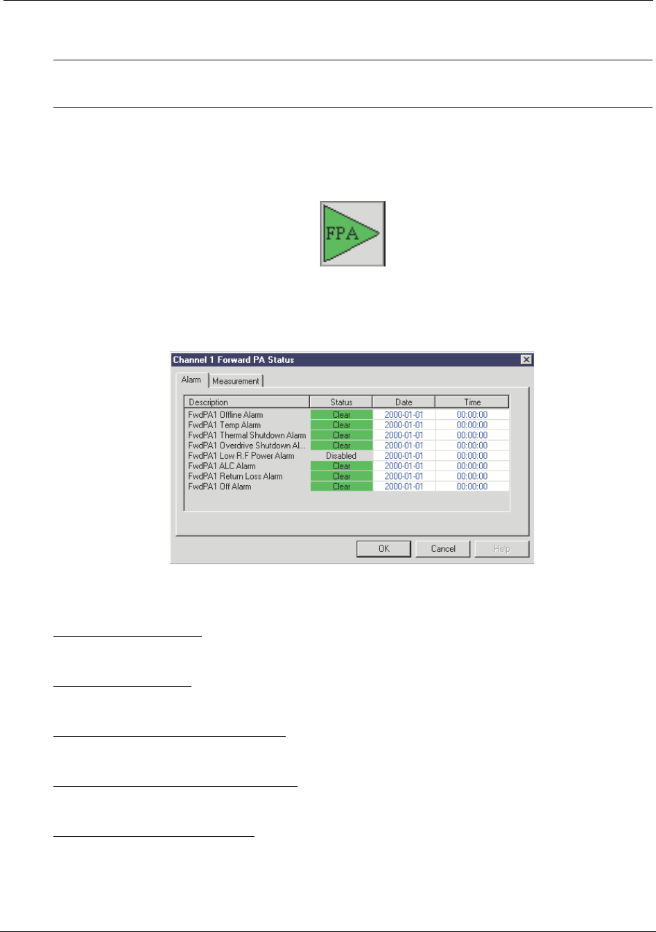
Forward Power Amplifier (FPA) Status Reporting
NOTE: The alarm status and monitoring points are the same for both FPA icons with the
exception of the labeling of channel 1 versus channel 2.
By clicking on the FPA icon you will bring up the FPA Alarm Status display shown in
Figure 5-9:
Figure 5-9 Forward Power Amplifier (FPA) Status
This display shows the status of the following alarms:
FwdPA Offline Alarm- Indicates that the ACU cannot communicate with the FPA over
the serial bus
FwdPA Temp Alarm- Indicates that the FPA is getting too hot and will shut itself off if the
condition causing the overheating is not rectified.
FwdPA Thermal Shutdown Alarm- Indicates that the FPA has been shut off (disabled)
due to over heating conditions.
FwdPA Overdrive Shutdown Alarm- Indicates the FPA has been shut down due to an
over drive condition.
FwdPA Low RF Power Alarm- Indicates that the forward power level coming out of the
FPA has been low for a preset amount of time (default is 5 minutes, but is adjustable by
RT222125
RT221101
Reference Manual Configuring the Repeater
550-1300-01 Rev C RTI Confidential 5-13
the user). This indicates either a problem in the FPA, repeater, or the base station feeding
the repeater.
FwdPA ALC Alarm- Indicates that the forward gain of the repeater has been reduced in
order to compensate for an RF over drive condition in the FPA.
FwdPA Return Loss Alarm- Indicates that a high VSWR condition exists on the output
port of the FPA. This could either be caused by internal hardware or external antenna
connections.
FwdPA Off Alarm - Indicates the forward PA has been shut off.
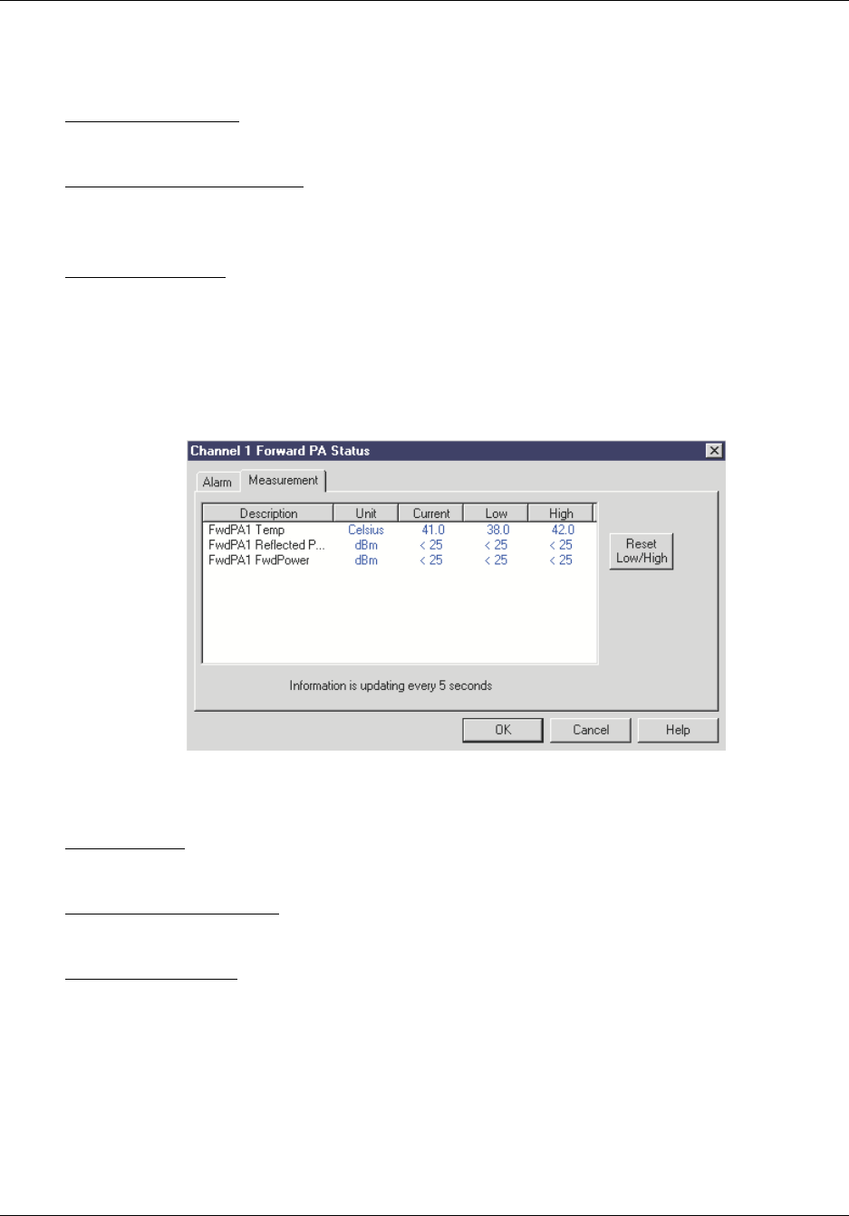
By pressing on the Measurement tab the measurement status window will be displayed
as shown in Figure 5-10:
Figure 5-10 FPA Measurement
This window displays the following measurement data from the FPA:
FwdPA Temp - The temperature of the forward PA is displayed in degrees Celsius. Cur-
rent, Low and High values are displayed.
FwdPA Reflected Power - The reflected power at the output of the repeater is displayed
in dBm. Current, Low and High values are displayed.
FwdPA Fwd Power - The output power of the FPA is displayed in dBm. Current, Low
and High values are displayed.
There is also a reset Low/High values button that will clear the minimum and maximum
displays.
RT222101
Configuring the Repeater Reference Manual
5-14 RTI Confidential 550-1300-01 Rev C
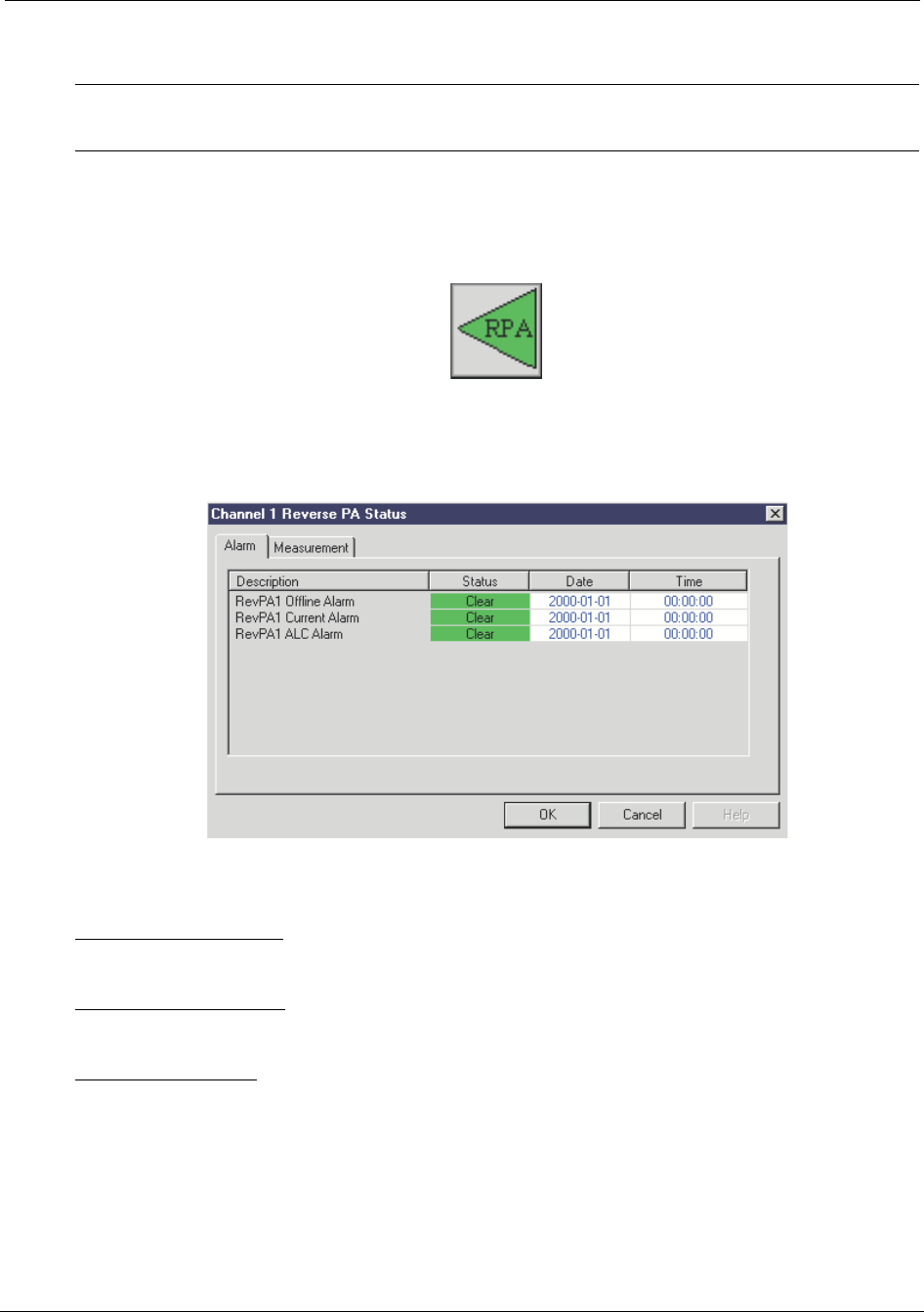
Reverse Power Amplifier (RPA) Status Reporting
NOTE: The alarm status and monitoring points are the same for both FPA icons with the
exception of the labeling of channel 1 versus channel 2.
By clicking on the Reverse Power Amplifier (RPA) icon you will bring up the RPA Alarm
Status display shown in Figure 5-11:
Figure 5-11 Reverse Power Amplifier (RPA) Status
This display shows the status of the following alarms:
RevPA Offline Alarm - Indicates that the ACU cannot communicate with the RPA over
the serial bus.
RevPA Current Alarm - This alarm activates when the RPA is drawing either too much or
too little current.
RevPA ALC Alarm - Indicates that the reverse gain of the repeater has been reduced in
order to compensate for an RF over drive condition in the RPA.
By pressing on the Measurement tab the measurement status window will be displayed
as shown in Figure 5-12:
RT222126
RT222102
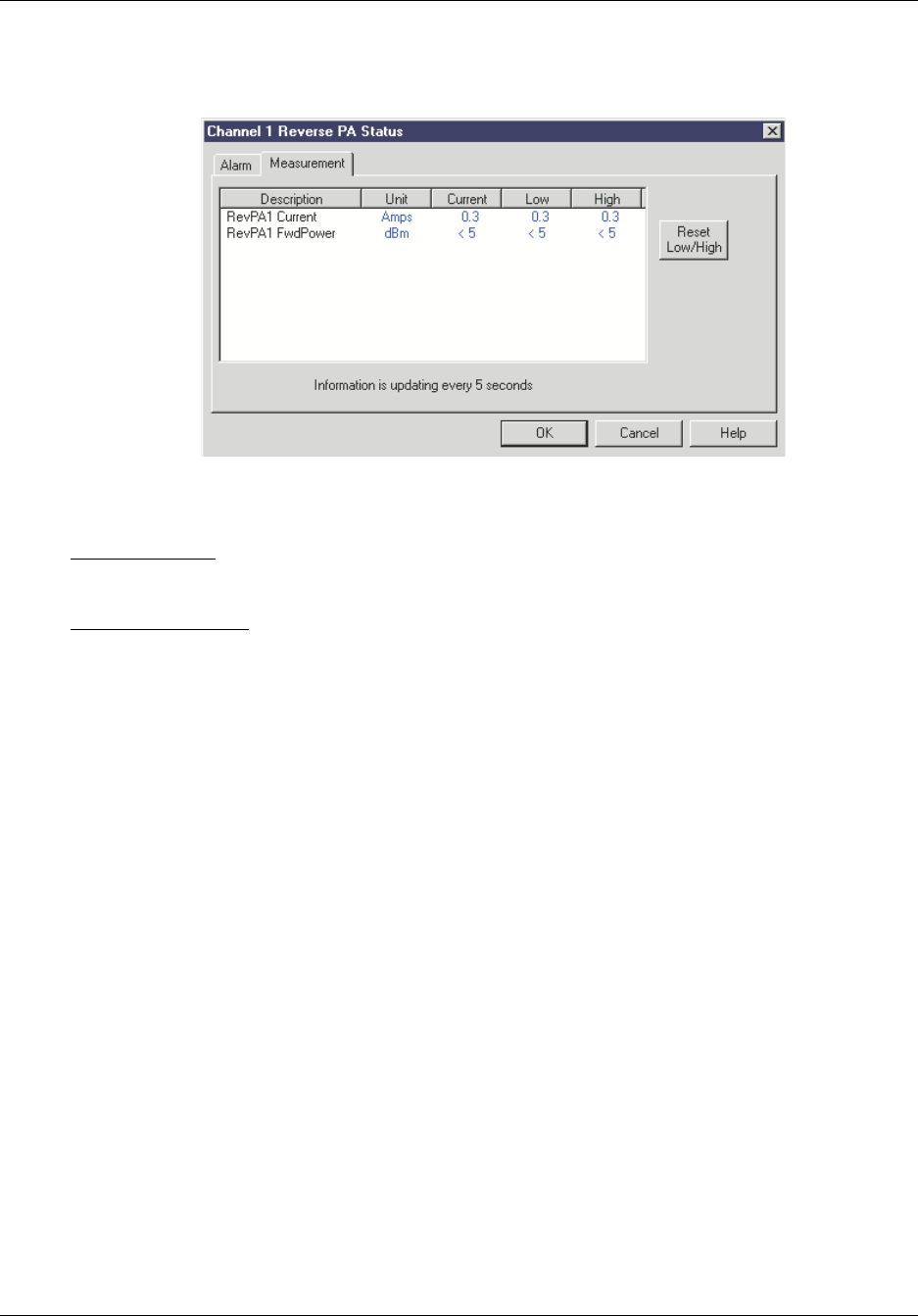
Reference Manual Configuring the Repeater
550-1300-01 Rev C RTI Confidential 5-15
Figure 5-12 RPA Measurement
This window displays the following measurement data from the RPA:
RevPA Current - The RPA current is displayed in Amps. Current, Low and High values
are displayed.
RevPA Fwd Power - The output power of the RPA is displayed in dBm. Current, Low and
High values are displayed.
There is also a reset Low/High values button that will clear the minimum and maximum
displays.
RT222103
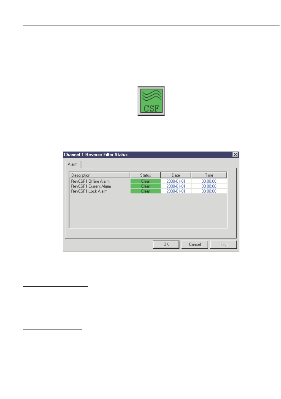
Configuring the Repeater Reference Manual
5-16 RTI Confidential 550-1300-01 Rev C
Reverse Channel Select Filter (CSF) Channel 1 and 2 Status Reporting
NOTE: The alarm status and monitoring points are the same for both Reverse CSF icons
with the exception of the labeling of channel 1 versus channel 2.
By clicking on the Reverse Channel Select Filter (CSF) icon you will bring up the CSF
Alarm Status display shown in Figure 5-13:
Figure 5-13 Reverse CSF Status
This display shows the status of the following alarms:
RevCSF Offline Alarm - This alarm activates when the ACU cannot communicate to the
CSF through the serial bus.
RevCSF Current Alarm - This alarm activates when the CSF is drawing either too much
or too little current.
RevCSF Lock Alarm: This alarm activates when the phase locked loops that control the
CSF up / down conversion circuitry lose lock. This alarm causes the CSF frequency to
become unstable, so in order to prevent spurious outputs from the repeater the power
amplifier associated with this CSF is shut down, therefore turning off the channel.
RT222127
RT222104
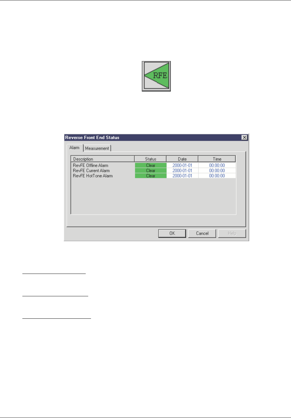
Reference Manual Configuring the Repeater
550-1300-01 Rev C RTI Confidential 5-17
Reverse Front End (RFE) Status Reporting
By clicking on the Reverse Front End (RFE) icon you will bring up the RFE Alarm Status
display shown in Figure 5-14:
Figure 5-14 RFE Status
This display shows the status of the following alarms:
RevFE Offline Alarm - This alarm activates when the ACU cannot communicate to the
RFE through the serial bus.
RevFE Current Alarm - This alarm activates when the reverse front end is drawing either
too much or too little current.
RevFE HotTone Alarm - This alarm activates when the reverse signal power level is too
strong, and is being attenuated to protect the repeater from possible damage.
By pressing on the Measurement tab the measurement status window will be displayed
as shown in Figure 5-15:
RT222128
RT222105
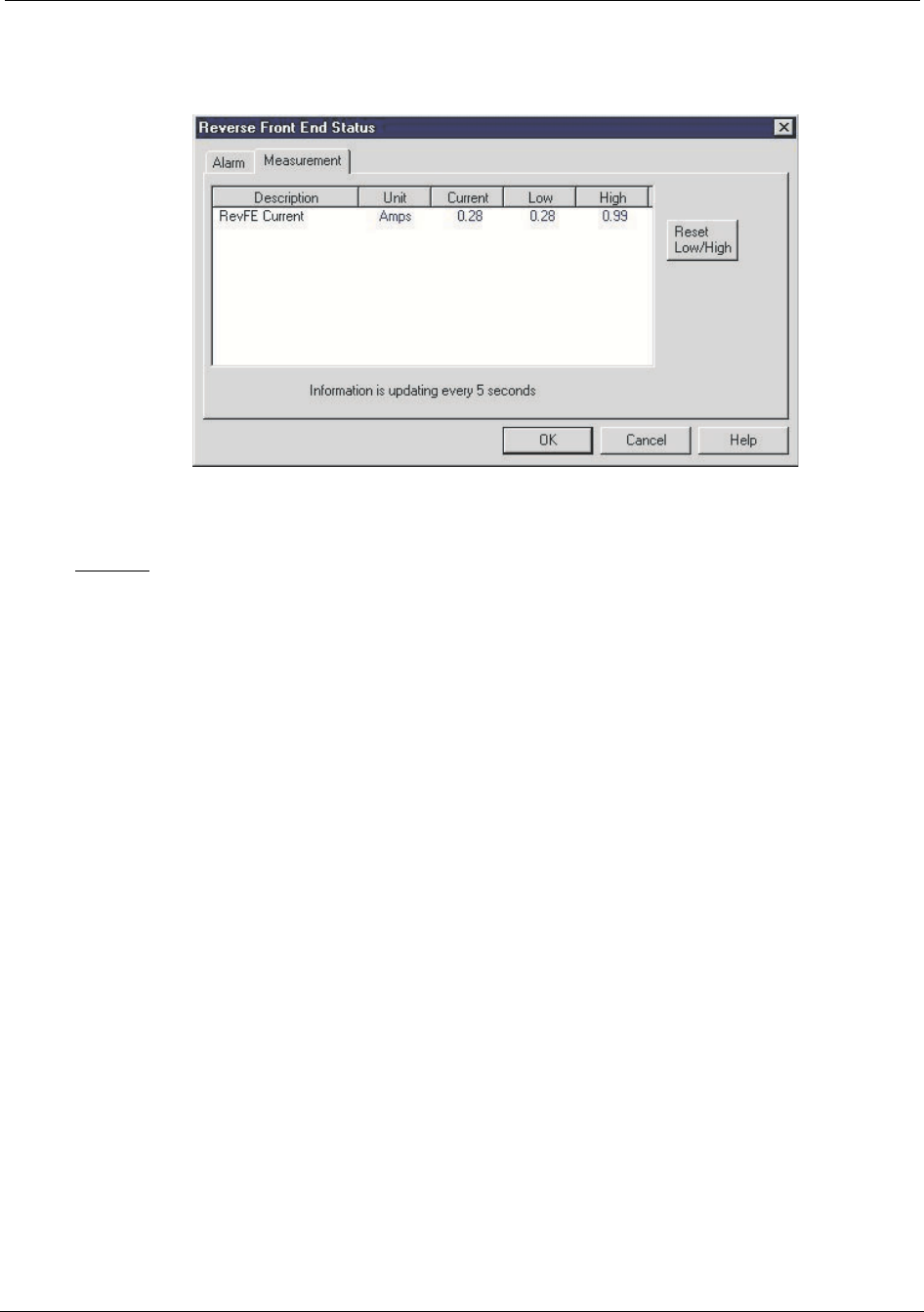
Configuring the Repeater Reference Manual
5-18 RTI Confidential 550-1300-01 Rev C
Figure 5-15 RFE Measurement
This window displays the following measurement data from the RFE module:
Current - The RFE current is displayed in Amps. Current, Low and High values dis-
played.
There is also a reset Low/High values button that will clear the minimum and maximum
displays.
RT286101
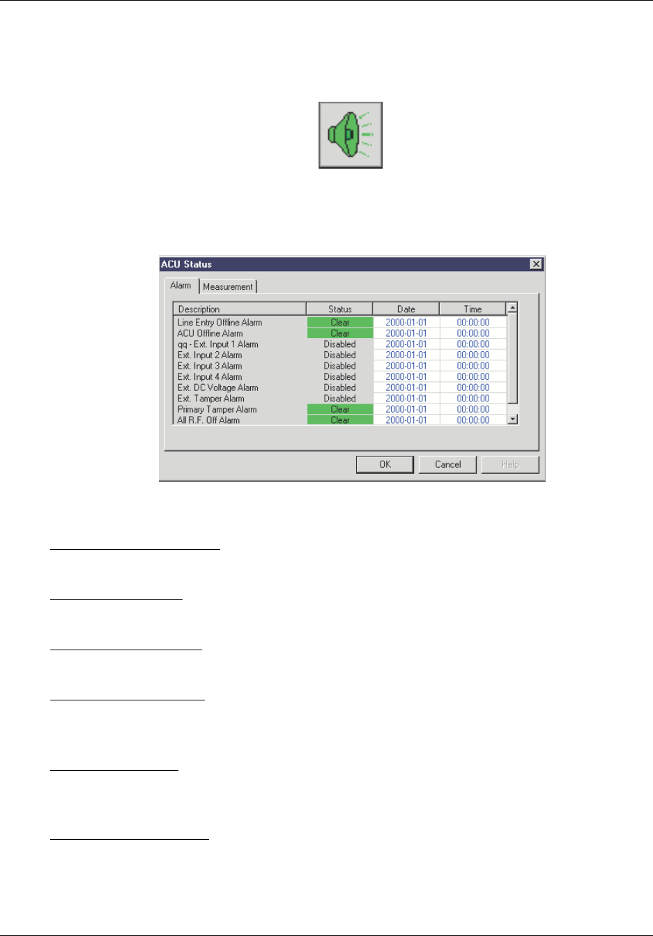
Reference Manual Configuring the Repeater
550-1300-01 Rev C RTI Confidential 5-19
Alarm Control Unit (ACU) Status Reporting
By clicking on the Alarm Control Unit (ACU) icon you will bring up the RFE Alarm Sta-
tus display shown in Figure 5-16:
Figure 5-16 Alarm Control Unit (ACU) Status
This display shows the status of the following alarms:
Line Entry Offline Alarm - Indicates the ACU cannot communicate with the line entry
module over the serial bus.
ACU Offline Alarm - Indicates the ACU cannot communicate with its own I/O processor
over the serial bus. Probably means that the bus is inoperative or shorted out.
Ext. Input 1 - 4 Alarms - Indicates that one of the 4 external input alarms are active. These
alarms are user configured to communicate with devices external to the repeater.
Ext. DC Voltage Alarm - Indicates the voltage applied to this interface is out of the range
specified by the user. This alarm is meant to monitor an external DC voltage supply and
alarm on an out of range condition specified by the user.
Ext. Tamper Alarm - Indicates that a tamper switch external to the repeater (storage closet
door, system enclosure, base station door,…) has been opened indicating an entry into a
restricted area. The default alarm state is disabled.
Primary Tamper Alarm - Indicates someone has opened the repeater door.
RT222129
RT222107
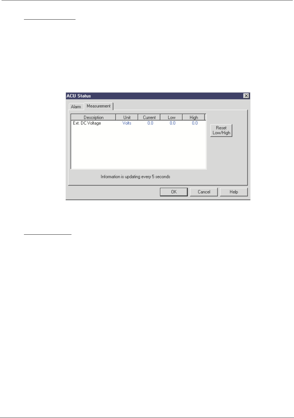
Configuring the Repeater Reference Manual
5-20 RTI Confidential 550-1300-01 Rev C
All RF Off Alarm - Indicates that the main power to the repeater has failed and the unit is
now running on the small back up battery. All the RF modules have been disabled and
there is no RF power being transmitted by the repeater.
By pressing on the Measurement tab the measurement status window will be displayed
as shown in Figure 5-17:
Figure 5-17 ACU Measurement
This window displays the following measurement data from the ACU module:
Ext. DC Voltage - The external DC voltage being monitored is displayed in volts. Current,
Low and High values are displayed. There is a reset Low/High values button that will
clear the minimum and maximum displays.
RT222108
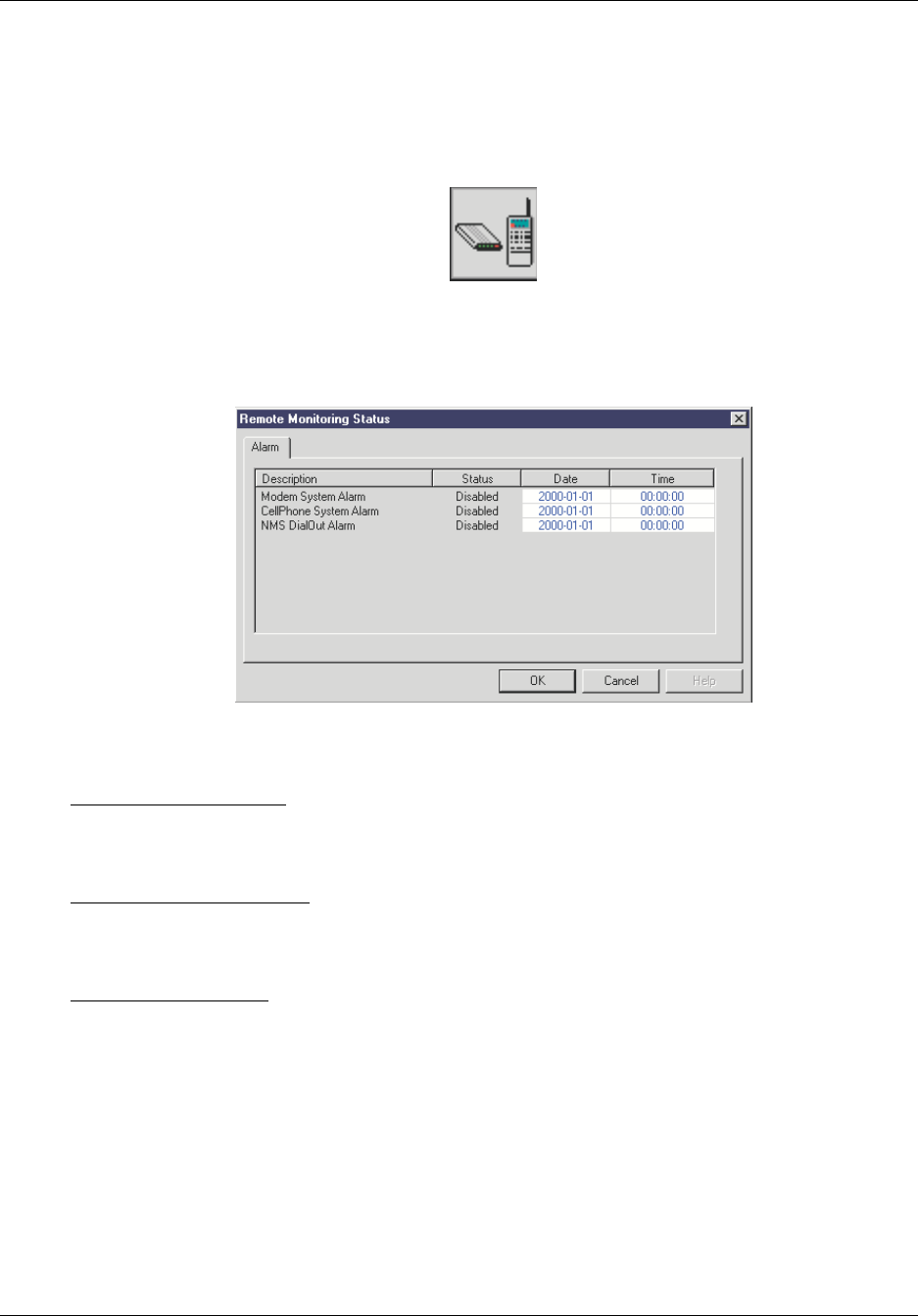
Reference Manual Configuring the Repeater
550-1300-01 Rev C RTI Confidential 5-21
Remote Monitoring Status Reporting
By clicking on the Remote Monitoring icon you will bring up the Remote Monitoring
Alarm Status display shown in Figure 5-18:
Figure 5-18 Remote Monitoring Status
This display shows the status of the following alarms:
Modem System Alarm - Indicates that the ACU cannot communicate with or configure
the attached modem. This alarm is only active if the repeater has been provisioned with a
modem.
CellPhone System Alarm - Indicates the ACU cannot communicate with or configure the
attached cell phone. This alarm is only active if the repeater has been provisioned with a
cell phone.
NMS DialOut Alarm - Indicates that the ACU has been unable to dial out an alarm to the
Network Management system. This alarm is only active if the repeater has been provi-
sioned with a monitoring kit and has had the NMS dial out options configured.
RT222130
RT222109
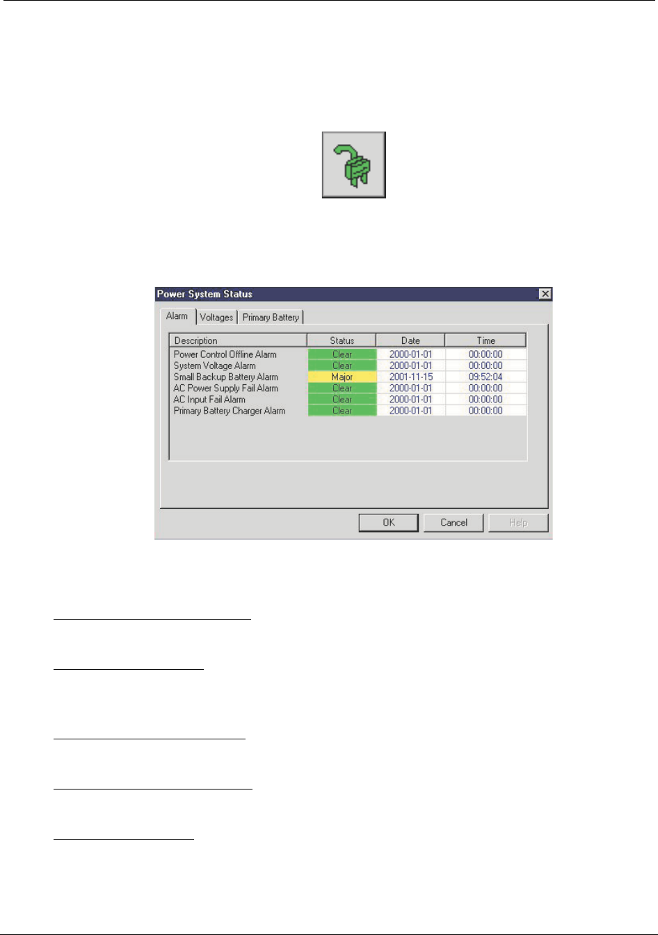
Configuring the Repeater Reference Manual
5-22 RTI Confidential 550-1300-01 Rev C
Power System Status Reporting
By clicking on the Power System icon you will bring up the Remote Monitoring Alarm
Status display shown in Figure 5-19:
Figure 5-19 Power System Status
This display shows the status of the following alarms:
Power Control Offline Alarm - Indicates the ACU cannot communicate with the power
control system over the serial bus.
System Voltage Alarm - Indicates the DC power rail inside the repeater (provided by the
user on a DC powered system) has gone under 20 VDC or over 32 VDC (outside the spec-
ified limits).
Small Backup Battery Alarm - Indicates the small back up battery (located on the door of
the repeater) has failed the load test and needs to be replaced.
AC Power Supply Fail Alarm - DC output failure alarm from the AC/DC power supply.
Only active in AC powered systems.
AC Input Fail Alarm - AC input voltage failure alarm from the AC power source. Only
active in AC powered systems.
RT222131
RT330102
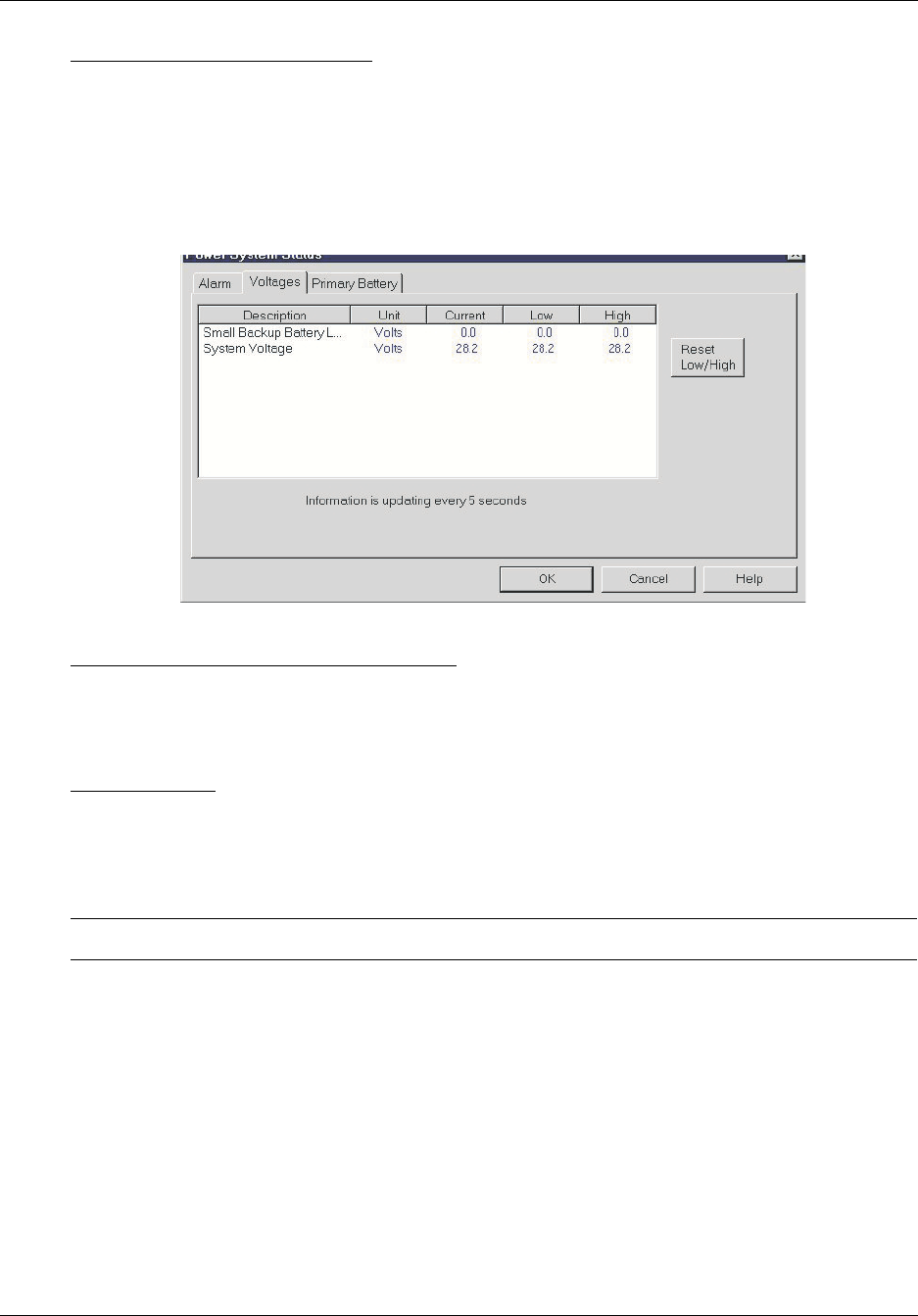
Reference Manual Configuring the Repeater
550-1300-01 Rev C RTI Confidential 5-23
Primary Battery Charger Alarm - Indicates that the primary battery (large batteries
located outside of the repeater) charging circuit has failed and is no longer charging the
batteries.
By clicking on the Voltages tab (Figure 5-20) the following measurements are displayed:
Figure 5-20 Power System Voltages display here
Small Back-up Battery Load Test Voltage - The results from a one minute load test per-
formed on the small back-up battery is displayed in volts. The load test is run every hour
(to prevent discharging the battery) and should show a result of over 11.5 VDC if the bat-
tery is good. Current, Low and High values are displayed.
System Voltage - The repeater’s internal DC bus is displayed in volts. Current, Low and
High values are displayed.
There is a reset Low/High values button that will clear the minimum and maximum dis-
plays.
NOTE: May be up to 700 mV lower than the voltage at the terminal block.
RT337101
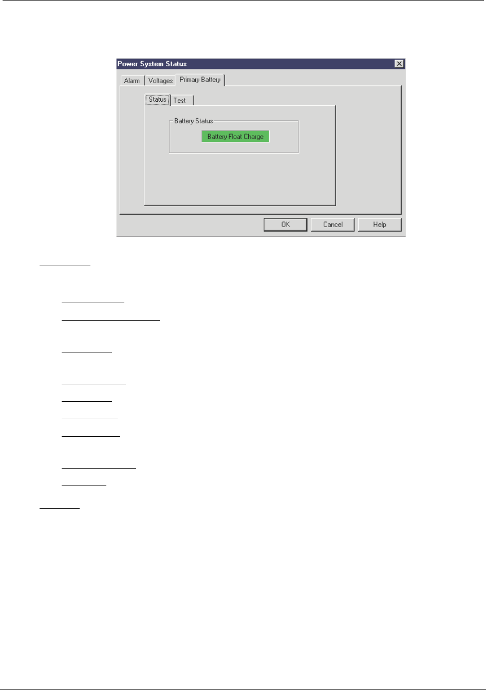
Configuring the Repeater Reference Manual
5-24 RTI Confidential 550-1300-01 Rev C
Figure 5-21 Power System Primary Battery
Status Tab - This shows the current state of the primary battery charger circuit. The states
are as follows:
Start Charge - initial state where the charger is checking the state of battery.
Battery Fast Charge - The charger is providing up to 2 Amps of current into the bat-
teries.
Transition - The charger has reached the top of the charging voltage range during fast
charge and is cutting back the current to a float charge level.
Maintenance - Float charge level.
Discharge - Repeater is operating on battery supplied power.
Over Temp - Charger has been disabled due to the batteries being too hot.
Open Relay - Battery charger has been disabled due to either an open relay or open
circuit breaker to the battery.
Charger Failed - Charger was unable to charge the batteries.
Disabled - Battery charger is disabled.
Test Tab - This tab allows the user to run a load test on the external batteries. The load test
takes 24 hours to perform. The test opens the circuit to the battery for 24 hours and allows
the battery's internal resistance to bleed off the charging voltage then measures the bat-
tery voltage to determine how much capacity the battery still has.
RT222112
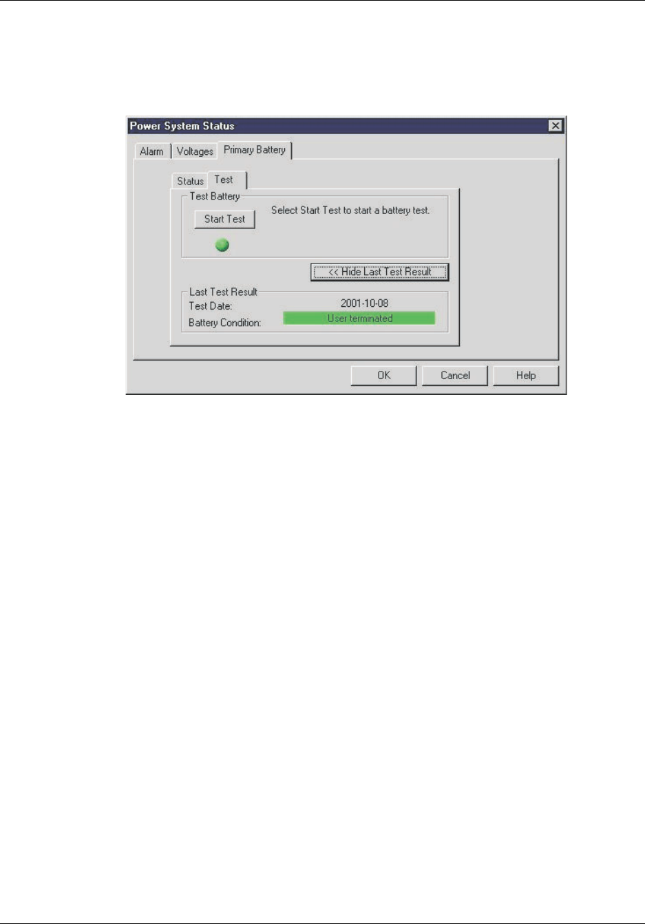
Reference Manual Configuring the Repeater
550-1300-01 Rev C RTI Confidential 5-25
By clicking on the Primary Battery tab the following screen is displayed:
Figure 5-22 Primary Test Tab
RT286103
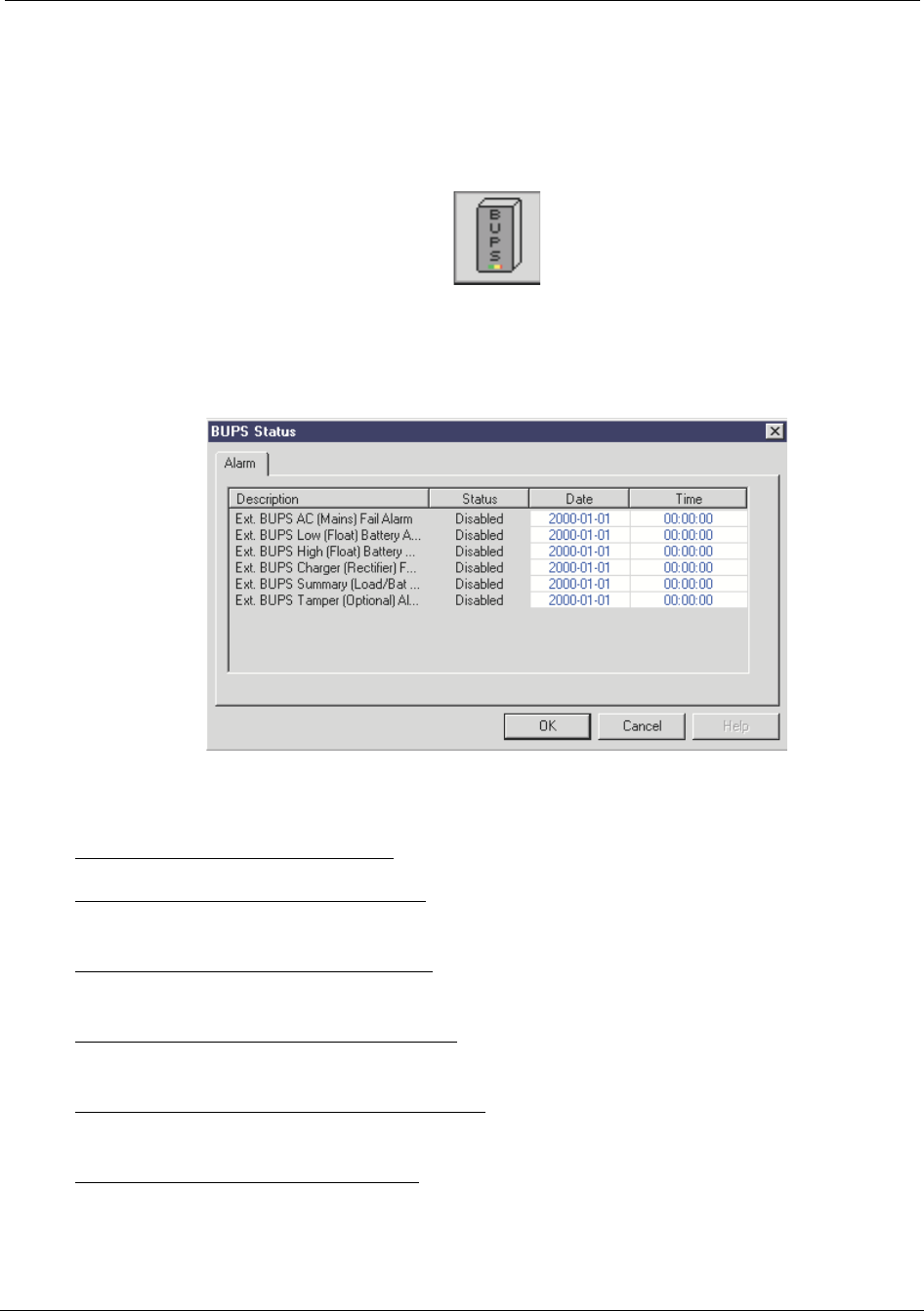
Configuring the Repeater Reference Manual
5-26 RTI Confidential 550-1300-01 Rev C
External Back Up Power System (BUPS) Status Reporting
By clicking on the BUPS icon you will bring up the BUPS Status display shown in
Figure 5-23:
Figure 5-23 BUPS Status
This display shows the status of the following alarms:
Ext. BUPS AC (Mains) Fail Alarm - Indicates the external BUPS has lost AC power
Ext. BUPS Low (Float) Battery Alarm - Indicates the external BUPS has dropped down to
a low float voltage on the batteries.
Ext. BUPS High (Float) Battery Alarm - Indicates the external BUPS has reached the high
float voltage on the batteries.
Ext. BUPS Charger (Rectifier) Fail Alarm - Indicates the external BUPS rectifier circuit has
failed.
Ext. BUPS Summary (Load/Battery) Alarm - Indicates an alarm has activated in the
external BUPS.
Ext. BUPS Tamper (Optional) Alarm - Indicates the door to the external BUPS is open.
RT222132
RT222114
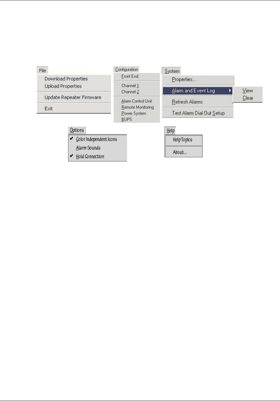
Reference Manual Configuring the Repeater
550-1300-01 Rev C RTI Confidential 5-27
5.7 Configuring Repeater Properties/Alarm Severities
Craft Pull-down menus are used to configure the repeater.
Figure 5-24 Craft Pull-down menus
All RTI repeaters are shipped with PAs (Power Amplifiers) turned Off. In this condition,
the PA Off indicator (a circle with a slash through it) is displayed over each PA subsystem
icon (FPA and RPA) in the Craft Main Control Screen. Keep each repeater's PA turned Off,
until you have adjusted the gain for that repeater.
The appearance of the Main Control Screen (and the available menus) might vary from
that shown in Figure 5-6 and on the following pages, depending on the repeater hard-
ware configuration.
RT249105

Configuring the Repeater Reference Manual
5-28 RTI Confidential 550-1300-01 Rev C
5.7.1 Subsystem Configuration
To configure the repeater, select the subsystem Properties screens from the Craft Configu-
ration menu.
Table 5-2 lists the choices in the Configuration menu.
Table 5- 2 Con f igur at ion Menu
Menu Selection Description Section
Front End Configures the Forward, Reverse,
and Diversity front ends
See “Front End Properties” .
Channel 1 Configures repeater channel 1. See “Channel1 and Channel2 Properties” .
Channel 2 Configures repeater channel 2. See “Channel1 and Channel2 Properties” .
Alarm Control Unit Configures ACU. See “Alarm Control Unit Properties” .
Remote Monitoring Configures Internal Modem/UART
and External cell phone.
See “Remote Monitoring Properties” .
Power System Configures input, battery, and
internal power.
See “Power System Properties” .
BUPS Configure Back-up Power System
(BUPS).
See “Back-up Power System (BUPS) Prop-
erties” .

Reference Manual Configuring the Repeater
550-1300-01 Rev C RTI Confidential 5-29
Use the subsystem Properties screens to configure the repeater.
To open a Properties screen, select one of the following subsystems from the Configura-
tion menu:
•Front End
•Channel 1
•Channel 2
•Alarm Control Unit
•Remote Monitoring
•Power System
•BUPS
The Properties screens display tabs that are specific to each subsystem. You can conduct
two types of repeater settings:
1. Redefine alarm severity
The levels of alarm severity are:
•Critical
•Major
•Minor
•Event
•Disabled
The Critical, Major, and Minor alarm levels are consistent with normal telecommuni-
cations definitions, and are ranked in that order. When an alarm is defined as an
event it will be logged in the error log, but will not cause the repeater to dial the NMS
or page a technician. When an alarm is disabled it is as if the alarm does not exist in
the system at all.
2. Specify operational settings for the repeater.
Some subsystem Properties screens include tabs for redefining alarm severity, and
for specifying operational settings. Others have a single tab, for redefining alarm
severity.
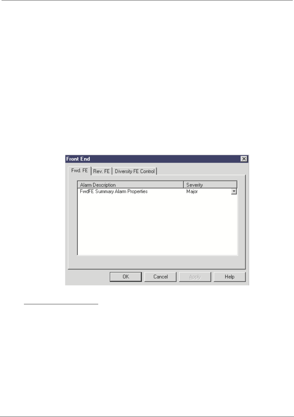
Configuring the Repeater Reference Manual
5-30 RTI Confidential 550-1300-01 Rev C
5.8 Front End Properties
The Front End Properties screen configures the Front End subsystems. This screen
includes tabs that set the alarm severity for:
•Forward FE
•Reverse FE
and a configuration tab in order to turn on or off the:
•Diversity FE
5.8.1 Forward FE Tab
The Forward FE tab (see Figure 5-25) sets the alarm severity of the Forward FE alarm.
Figure 5-25 Front End Properties Screen, Forward FE Tab
FwdFE Summary Alarm - This alarm activates when the forward front end is drawing
either too much or too little current.
To redefine the alarm severity for the Forward FE subsystem:
1. Click the down arrow next to the alarm field to select a new alarm severity.
2. Click the Apply or OK button to change the alarm severity.
•The Apply button changes the alarm severity and keeps the Channel Properties
screen open.
•The OK button changes the alarm severity and closes the Channel Properties
screen.
RT222115
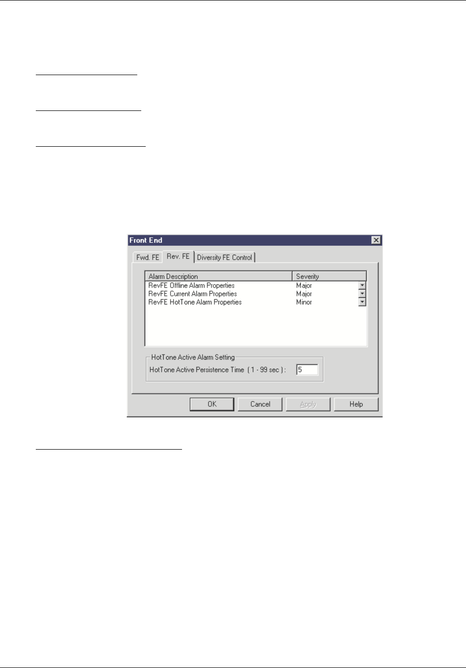
Reference Manual Configuring the Repeater
550-1300-01 Rev C RTI Confidential 5-31
5.8.2 Reverse FE Tab
The Reverse FE tab (see Figure 5-26) sets the alarm severity of the Reverse FE alarms.
RevFE Offline Alarm - This alarm activates when the ACU cannot communicate to the
RFE through the internal serial bus.
RevFE Current Alarm - This alarm activates when the reverse front end is drawing either
too much or too little current.
RevFE HotTone Alarm - This alarm activates when the reverse signal power level is too
strong, and is being attenuated to protect the repeater from possible damage.
Figure 5-26 Front End Properties Screen, Reverse FE Tab
HotTone Active Alarm Setting - Sets the duration in seconds for how long the HotTone
condition needs to exist before the repeater declares an alarm.
To redefine the alarm severity for the Reverse FE subsystem:
1. Click the down arrow next to the alarm field to select a new alarm severity.
2. Click the Apply or OK button to change the alarm severity.
•The apply button changes the alarm severity and keeps the Channel Properties
screen open.
•The OK button changes the alarm severity and closes the Channel Properties
screen.
RT222116
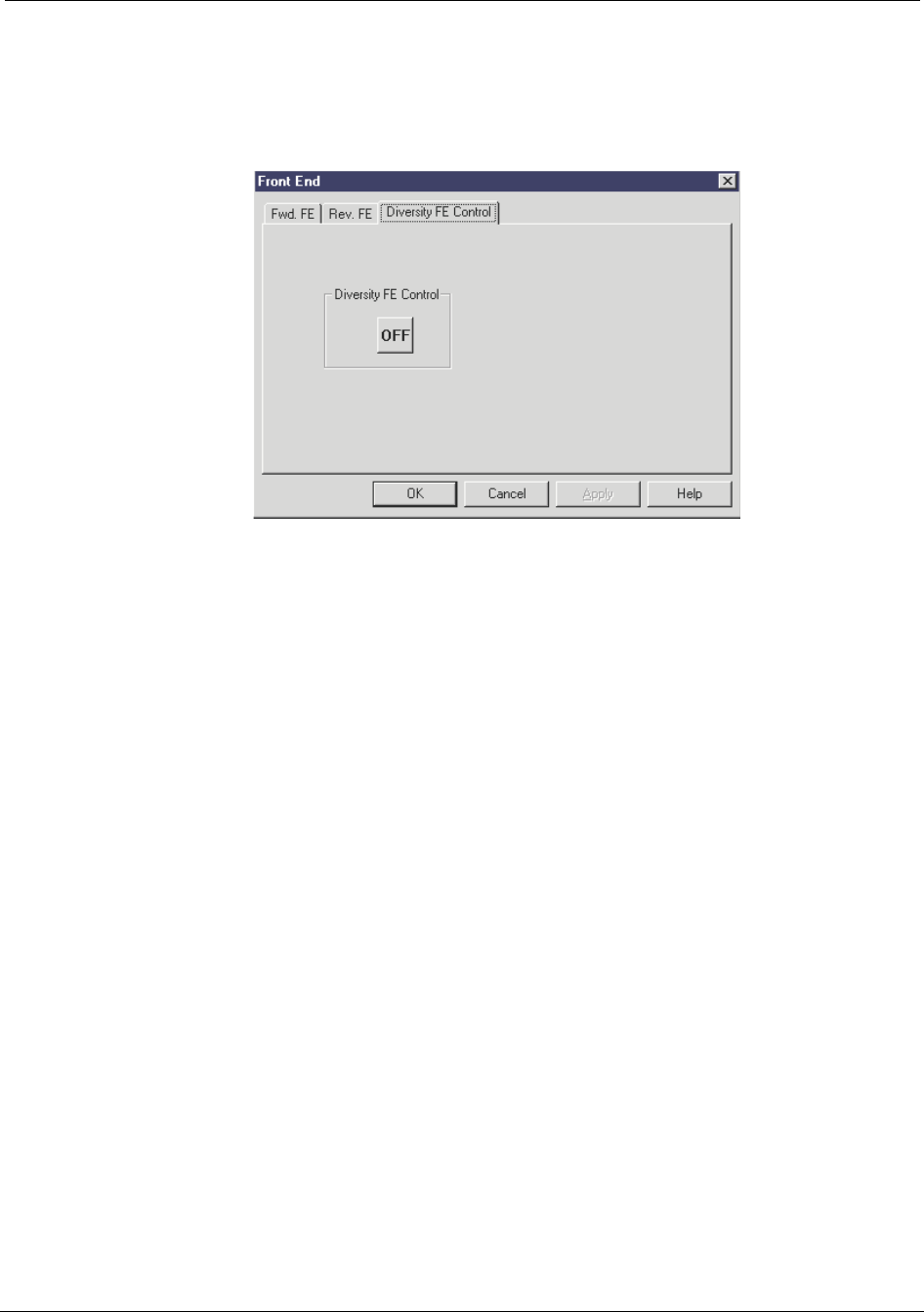
Configuring the Repeater Reference Manual
5-32 RTI Confidential 550-1300-01 Rev C
5.8.3 Diversity FE Control Tab
The Diversity FE tab (see Figure 5-27) allows you to turn the Diversity FE on or off.
Figure 5-27 Front End Properties Screen, Diversity FE Tab
RT222117
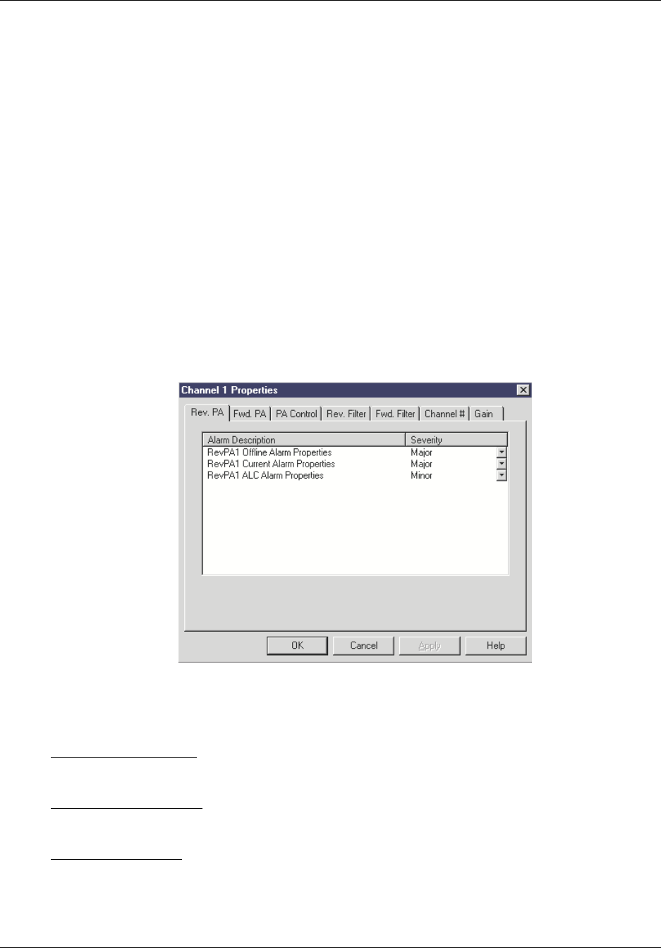
Reference Manual Configuring the Repeater
550-1300-01 Rev C RTI Confidential 5-33
5.9 Channel1 and Channel2 Properties
From the Main Control screen menu bar, select Channel 1 or Channel 2 to open a Channel
Properties screen. Channel properties include:
•Reverse PA
•Forward PA
•PA C ontrol
•Reverse Filter
•Forward Filter
•Channel #
•Gain
5.9.1 Channel Reverse PA Tab
Figure 5-28 Channel Properties Screen, Reverse PA Tab
The Reverse PA tab sets the alarm severity for the following types of Reverse Power
Amplifier alarms (see Figure 5-28):
RevPA Offline Alarm - Indicates that the ACU cannot communicate with the RPA over
the serial bus.
RevPA Current Alarm - This alarm activates when the RPA is drawing either too much or
too little current.
RevPA ALC Alarm - Indicates that the reverse gain of the repeater has been reduced in
order to compensate for an RF over drive condition in the RPA.
RT222118

Configuring the Repeater Reference Manual
5-34 RTI Confidential 550-1300-01 Rev C
To redefine an alarm severity for the Reverse PA subsystem:
1. Click the down-arrow next to an Alarm field to select a new alarm severity.
2. Click the Apply or OK button to change the alarm severity.
•The Apply button changes the alarm severity and keeps the Channel Properties
screen open.
•The OK button changes the alarm severity and closes the Channel Properties
screen.
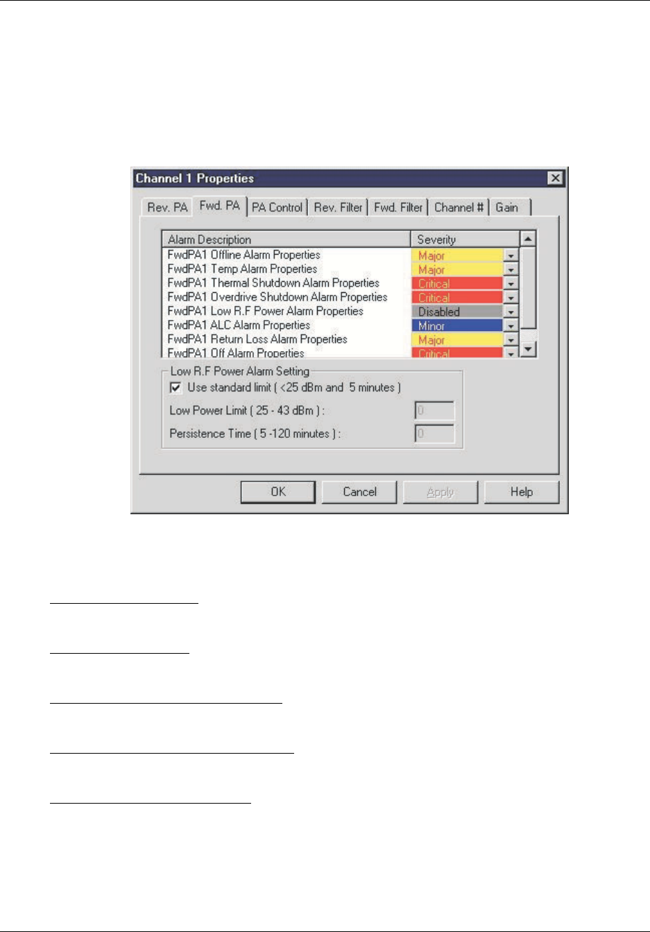
Reference Manual Configuring the Repeater
550-1300-01 Rev C RTI Confidential 5-35
5.9.2 Channel Forward PA Tab
The Forward PA tab (see Figure 5-29) sets the alarm severity for the following types of
Forward PA alarms:
Figure 5-29 Channel Properties Screen, Forward PA Tab
FwdPA Offline Alarm - Indicates that the ACU cannot communicate with the FPA over
the serial bus.
FwdPA Temp Alarm - Indicates that the FPA is getting too hot and will shut itself off if
the condition causing the overheating is not rectified.
FwdPA Thermal Shutdown Alarm - Indicates that the FPA has been shut off (disabled)
due to over heating conditions.
FwdPA Overdrive Shutdown Alarm - Indicates the FPA has been shut down due to an
over drive condition.
FwdPA Low RF Power Alarm - Indicates that the forward power level coming out of the
FPA has been low for a preset amount of time (default is 5 minutes, but is adjustable by
the user). This indicates either a problem in the FPA, repeater, or the base station feeding
the repeater.
RT286104

Configuring the Repeater Reference Manual
5-36 RTI Confidential 550-1300-01 Rev C
FwdPA ALC Alarm - Indicates that the forward gain of the repeater has been reduced in
order to compensate for an RF over drive condition in the FPA.
FwdPA Return Loss Alarm - Indicates that a high VSWR condition exists on the output
port of the FPA. This could either be caused by internal hardware or external antenna
connections.
FwdPA Off Alarm - Indicates that the forward PA is off.
To redefine an alarm severity for the Forward PA subsystem:
1. Click the down-arrow next to an Alarm field to select a new alarm severity.
2. Click the Apply or OK button to change the alarm severity.
•The Apply button changes the alarm severity and keeps the Channel Properties
screen open.
•The OK button changes the alarm severity and closes the Channel Properties
screen.
Low RF Power Alarm Setting - Allows a user to adjust the low RF Power Alarm in order
to make it useful in the network. This alarm will monitor the forward power out of the
repeater and alarm if it is below the low power limit for the persistence time.
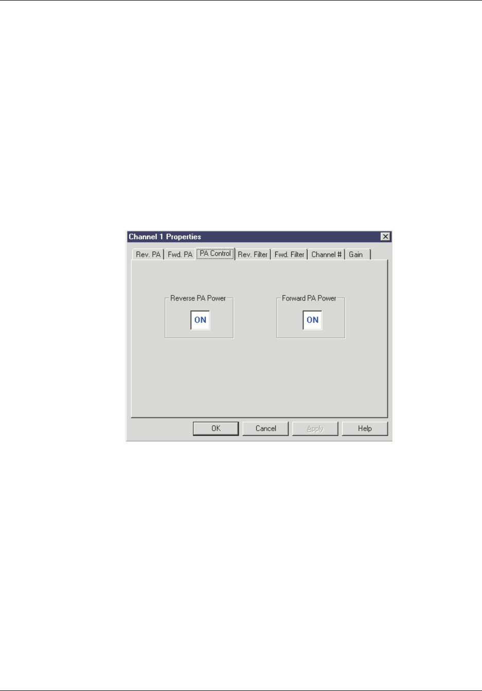
Reference Manual Configuring the Repeater
550-1300-01 Rev C RTI Confidential 5-37
5.9.3 Channel PA Control Tab
The PA Control tab provides a switch to turn PA power On or Off (see Figure 5-30).
1. Click on the Reverse PA Power box, or the Forward PA Power box to change the on
or off state of the PA.
The icon toggles between On and Off.
2. Click on the Apply or OK button for the setting to take effect.
•The Apply button changes the PA value and keeps the Channel Properties screen
open.
•The OK button changes the PA value and closes the Channel Properties screen.
Figure 5-30 Channel Properties Screen, Channel PA Tab
RT222120
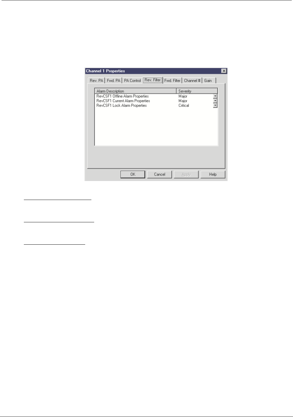
Configuring the Repeater Reference Manual
5-38 RTI Confidential 550-1300-01 Rev C
5.9.4 Channel Reverse Filter Tab
The Channel Reverse Filter tab sets the alarm severity for the following alarms:
Figure 5-31 Channel Properties Screen, Reverse Filter Tab
RevCSF Offline Alarm - This alarm activates when the ACU cannot communicate to the
CSF through the serial bus.
RevCSF Current Alarm - This alarm activates when the CSF is drawing either too much
or too little current.
RevCSF Lock Alarm: This alarm activates when the phase locked loops that control the
CSF up/down conversion circuitry lose lock. This alarm causes the CSF frequency to
become unstable, so in order to prevent spurious outputs from the repeater the power
amplifier associated with this CSF is shut down, therefore turning off the channel.
RT221122

Reference Manual Configuring the Repeater
550-1300-01 Rev C RTI Confidential 5-39
To redefine an alarm severity for the Reverse Filter subsystem:
1. Click the down-arrow next to an Alarm field to select a new alarm severity:
2. Click the Apply or OK button.
•The Apply button changes the alarm severity setting and keeps the Channel Prop-
erties screen open.
•The OK button changes the alarm severity setting and closes the Channel Proper-
ties screen.
NOTE: The Channel Reverse Filter tab is similar to the Channel Forward Filter tab,
shown in Figure 5-32.
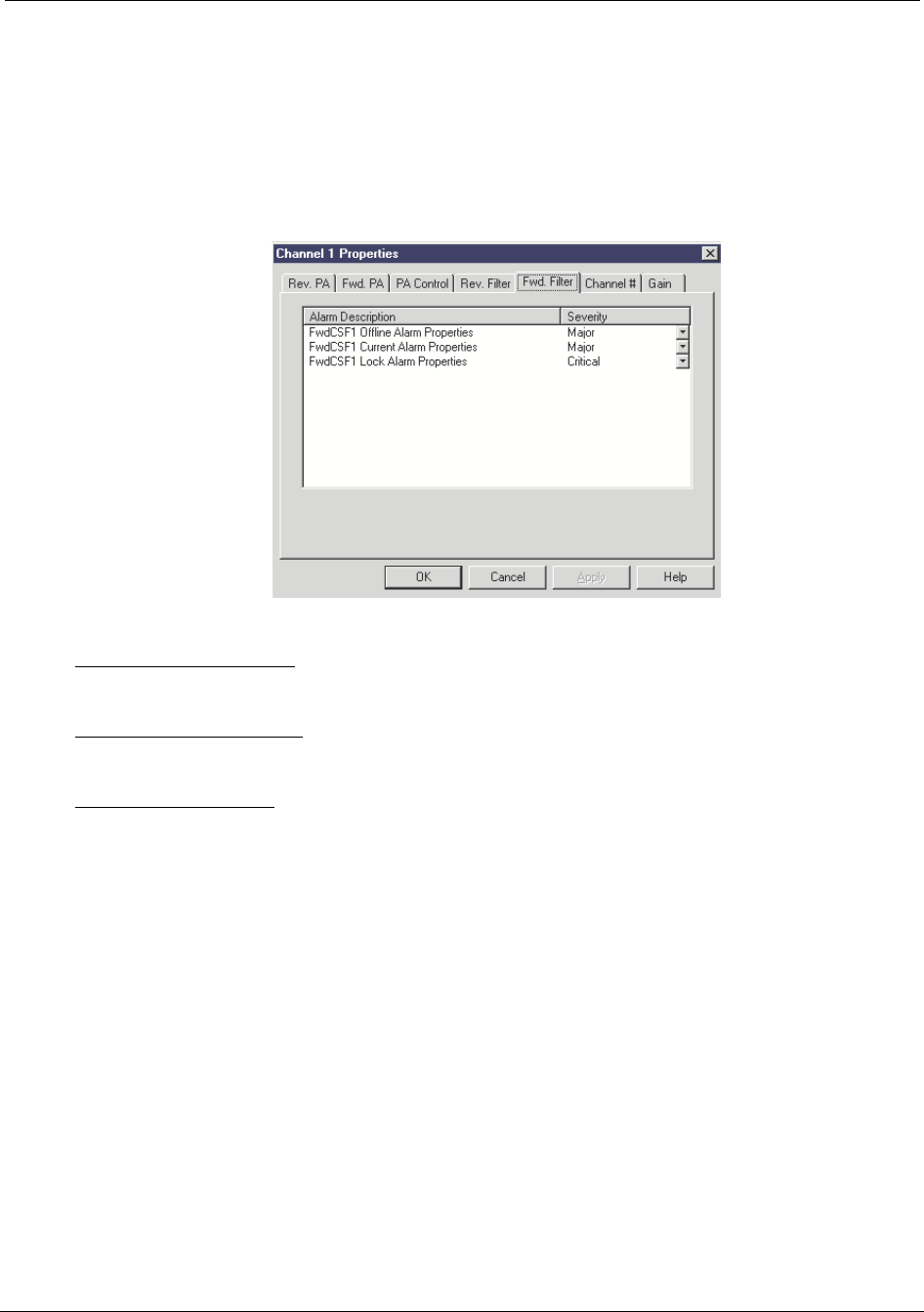
Configuring the Repeater Reference Manual
5-40 RTI Confidential 550-1300-01 Rev C
5.9.5 Channel Forward Filter Tab
The Channel Forward Filter tab (see Figure 5-32) sets the alarms severity for the follow-
ing alarms:
Figure 5-32 Channel Properties Screen, Channel Forward Filter Tab
FwdCSF Offline Alarm - This alarm activates when the ACU cannot communicate to the
CSF through the serial bus.
FwdCSF Current Alarm - This alarm activates when the CSF is drawing either too much
or too little current.
FwdCSF Lock Alarm: This alarm activates when the phase locked loops that control the
CSF up / down conversion circuitry lose lock. This alarm causes the CSF frequency to
become unstable, so in order to prevent spurious outputs from the repeater the power
amplifier associated with this CSF is shut down, therefore turning off the channel.
RT221121

Reference Manual Configuring the Repeater
550-1300-01 Rev C RTI Confidential 5-41
To redefine an alarm severity for the Forward Filter subsystem:
1. Click the down-arrow next to an Alarm filed to select a new alarm severity:
2. Click the Apply or OK button.
•The Apply button changes the alarm severity setting and keeps the Channel Prop-
erties screen open.
•The OK button changes the alarm severity setting and closes the Channel Proper-
ties screen.
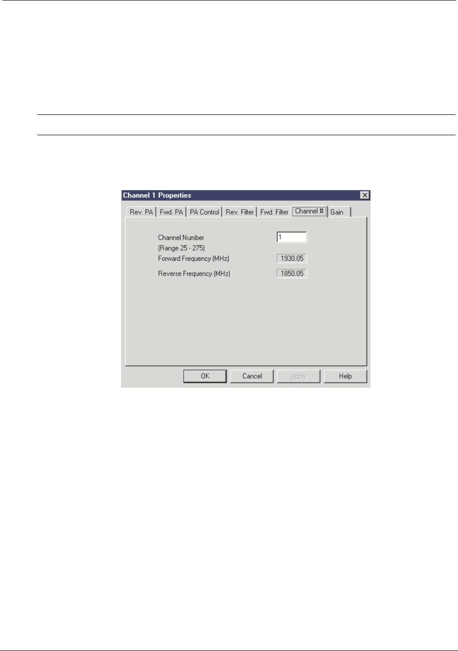
Configuring the Repeater Reference Manual
5-42 RTI Confidential 550-1300-01 Rev C
5.9.6 Channel # Tab
The Channel # tab (see Figure 5-33) sets the operating channel, for either Channel 1 or
Channel 2.
After you select a channel, the Channel Properties screen displays the corresponding fre-
quencies.
NOTE: Consult your RF engineer, or the system Site Plan, for the proper channel setting.
Figure 5-33 Channel Properties Screen, Channel # Tab
RT221120

Reference Manual Configuring the Repeater
550-1300-01 Rev C RTI Confidential 5-43
5.9.7 Channel Gain Tab
The RepeaterNet software detects the configuration of the repeater, and displays the
applicable gain range on the Gain tab (see Figure 5-34). You can adjust the Forward and
Reverse gain for the selected channel.
The adjustable gain range depends on the type of repeater, and the power level of the
repeater's power amplifiers. RepeaterNet limits your choice of gain adjustments to selec-
tions that are valid for the specific repeater type and power level.
NOTE: Carefully balance the gain in any repeater application to ensure proper hand-off
and system operation.
To adjust Forward PA or Reverse PA gain:
1. Select Configuration -> Channel 1 or Configuration -> Channel 2 to open the Chan-
nel Properties screen.
2. Click the Gain tab (see Figure 5-34).
3. Press, hold and drag the mouse across the horizontal sliders to define forward and
reverse gains.
NOTE: Gain is adjustable in 1 dB increments.
The gain value box (centered under each slider) displays the selected gain.
4. Click the Apply or OK button.
•The Apply button changes the gain setting and keeps the Channel Properties
screen open.
•The OK button changes the gain setting and closes the Channel Properties screen.
NOTE: The ALC setting needs to be turned off in order to adjust the gain. Turn the ALC
settings to off, adjust the gain, then turn it back on.
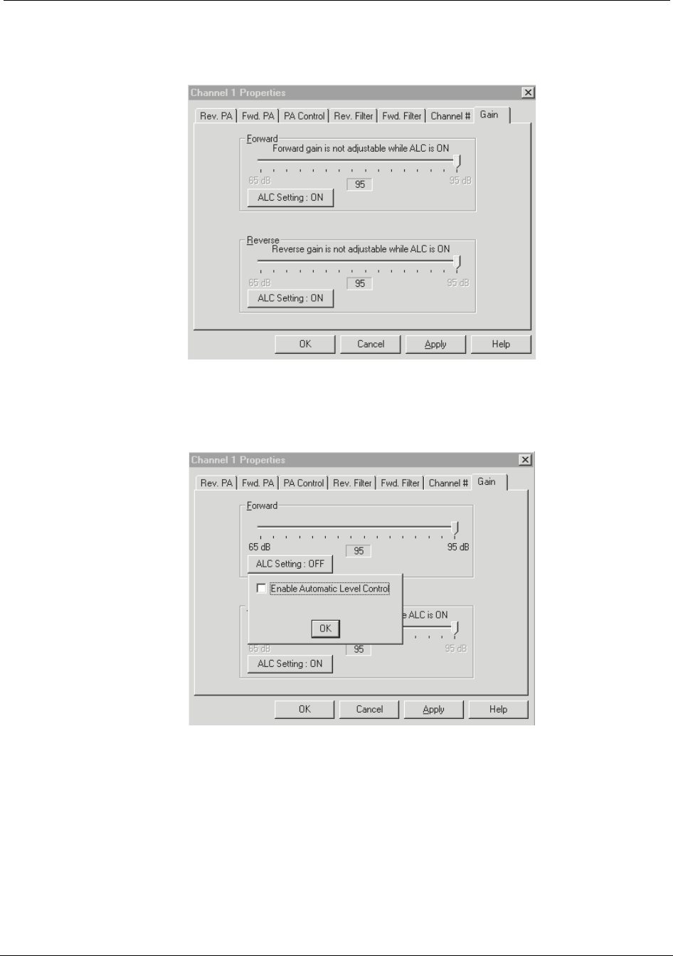
Configuring the Repeater Reference Manual
5-44 RTI Confidential 550-1300-01 Rev C
Figure 5-34 Channel Properties Screen, Channel Gain Tab ALC On
Figure 5-35 Channel Properties Screen, Channel Gain Tab ALC Off
RT221117
RT221118
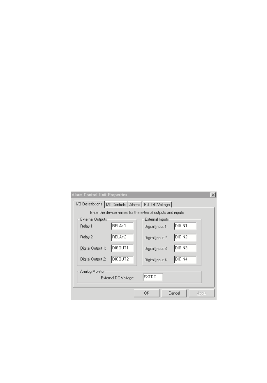
Reference Manual Configuring the Repeater
550-1300-01 Rev C RTI Confidential 5-45
5.10 Alarm Control Unit Properties
The Alarm Control Unit (ACU) subsystem provides alarm and control functions for the
repeater. The ACU monitors all repeater subsystems, and reports the status of a sub-
system, either to a directly-connected device, or to remote devices (through a dial-up
modem connection).
In addition to monitoring the repeater system, the ACU contains a number of external
inputs and outputs for monitoring and controlling external devices.
To monitor and control a repeater's alarms:
1. Select Alarm Control Unit from the Configuration menu, in the Main Control Screen.
The Alarm Control Unit Properties screen opens.
2. Select one of the following ACU tabs:
•I/O Descriptions
•I/O Control, Alarms
•Alarms
•Ext.DC Voltage
Figure 5-36 Alarm Control Unit
RT221116

Configuring the Repeater Reference Manual
5-46 RTI Confidential 550-1300-01 Rev C
5.10.1 ACU I/O Descriptions Tab
RepeaterNet can monitor four digital alarm inputs and one external DC voltage input
from external devices. Up to four external devices (two relay outputs and two digital out-
puts) can also be active.
Use the I/O Descriptions tab (see Figure 5-37) in the Alarm Control Unit Properties
screen to identify external equipment that is connected to the repeater's inputs and out-
puts.
External equipment could be a security light, or any other site equipment.
NOTE: For information about connecting inputs and outputs to a repeater, see chapter 6,
Connecting External Alarms and Relays.
To add I/O descriptions for the Alarm Control Unit, use the following procedure.
1. Select Configuration-> Alarm Control Unit.
The ACU Properties screen opens (see Figure 5-37). The I/O Descriptions tab is
active.
2. Provide I/O Descriptions in the screen's date fields.
Enter names for any or all of the following types of repeater inputs and outputs:
•Two different relay outputs
•Two different digital outputs
•One DC input
•Four different digital inputs
3. Click the Apply or OK button.
•The Apply button adds the repeater input or output and keeps the ACU Proper-
ties screen open.
•The OK button adds the repeater input or output and closes the ACU Properties
screen.
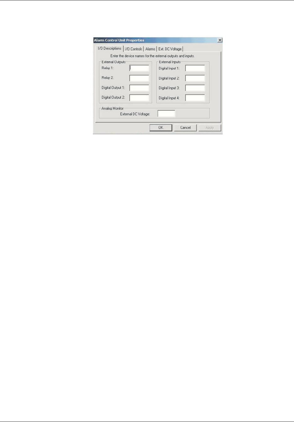
Reference Manual Configuring the Repeater
550-1300-01 Rev C RTI Confidential 5-47
Figure 5-37 ACU Properties Screen, I/O Descriptions Tab
RT211105
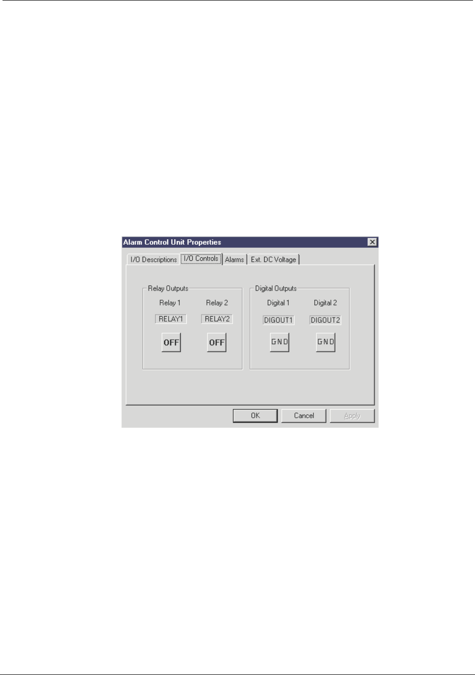
Configuring the Repeater Reference Manual
5-48 RTI Confidential 550-1300-01 Rev C
5.10.2 ACU I/O Controls Tab
The I/O Controls tab (see Figure 5-38) turn the 2 relay outputs and 2 digital outputs On
or Off.
1. Toggle the relay outputs either On or Off or the Digital Outputs to GND or Open Sta-
tus.
2. Click the Apply or Ok button.
•The Apply button turns the selected outputs either On or Off and keeps the ACU
Properties screen open.
•The OK button turns the selected outputs either On or Off and closes the ACU
Properties screen.
Figure 5-38 ACU Properties Screen, I/O Controls Tab
RT221115

Reference Manual Configuring the Repeater
550-1300-01 Rev C RTI Confidential 5-49
5.10.3 ACU Alarms Setting Tab
The Alarms tab (see Figure 5-39) redefines alarm severity for the ACU subsystem.
1. Click the down-arrow next to an Alarm field to select a new alarm severity:
NOTE: Alarm settings for External Input 1 through External Input 4 are default to Dis-
abled.
2. Click the Apply or OK button.
•The Apply button changes the alarm severity and keeps the ACU Properties
screen open.
•The OK button changes the alarm severity and closes the ACU Properties screen.
You can set the following alarms:
•Line Entry Offline Alarm - Indicates the ACU cannot communicate with the line
entry module over the serial bus.
•ACU Offline Alarm - Indicates the ACU cannot communicate with its own I/O
processor over the serial bus. Probably means that the bus is inoperative or
shorted out.
•Ext. Input 1 - 4 Alarms - Indicates that one of the 4 external input alarms are
active. These alarms are user configured to communicate with devices external to
the repeater.
•Ext. DC Voltage Alarm - Indicates the voltage applied to this interface is out of the
range specified by the user. This alarm is meant to monitor an external DC voltage
supply and alarm on an out of range condition specified by the user.
•Ext. Tamper Alarm - Indicates that a tamper switch external to the repeater (stor-
age closet door, system enclosure, base station door,…) has opened indicating an
entry into a restricted area. The default alarm state is disabled.
•Primary Tamper Alarm - Indicates the repeater door has been opened.
•All RF Off Alarm - Indicates that the main power to the repeater has failed and the
unit is now running on the small back up battery. All the RF modules have been
disabled and there is no RF power being transmitted by the repeater.
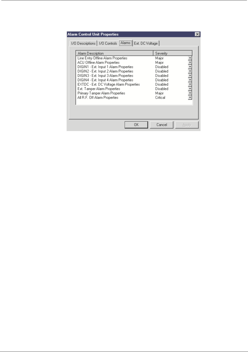
Configuring the Repeater Reference Manual
5-50 RTI Confidential 550-1300-01 Rev C
Figure 5-39 ACU Properties Screen, Alarms Tab
RT221114
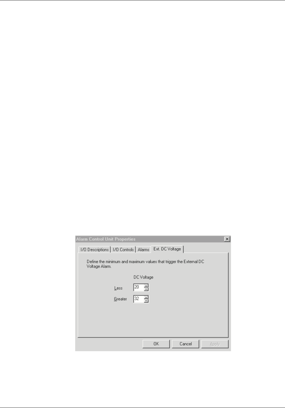
Reference Manual Configuring the Repeater
550-1300-01 Rev C RTI Confidential 5-51
5.10.4 External DC Voltage Alarm Threshold Tab
RepeaterNet can monitor an external DC voltage power source (a battery) from a range of
0 to 60 volts, in 1 volt increments. In addition to monitoring the voltage level, you can
define upper and lower limits for the voltage. Exceeding these limits activates the DC
voltage alarm in the ACU subsystem.
Use the Ext. DC Voltage tab to monitor the voltage of a user-supplied DC power source
used to power external site equipment. An alarm triggers if the voltage fluctuates outside
of a defined operating range.
To define an operating range for DC voltage:
1. Select Configuration -> Alarm Control Unit.
The ACU Properties screen opens.
2. Click the Ext. DC Voltage tab (see Figure 5-40).
3. Define (type in or arrow-click) the normal operating range for the DC power source,
in the Less Than and Greater Than data fields.
4. Click the Apply or OK button.
•The Apply button turns the selected outputs either On or Off and keeps the ACU
Properties screen open.
•The OK button turns the selected outputs either On or Off and closes the ACU
Properties screen.
Figure 5-40 ACU Properties Screen, External DC Voltage Tab
RT221113
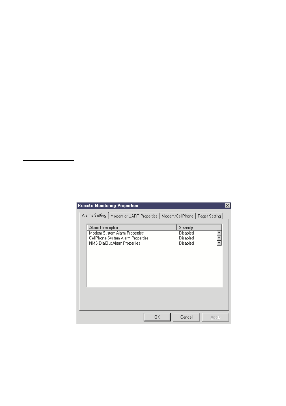
Configuring the Repeater Reference Manual
5-52 RTI Confidential 550-1300-01 Rev C
5.11 Remote Monitoring Properties
From the menu bar in the Main Control Screen, select Configuration -> Remote Monitor-
ing.
The Remote Monitoring Properties screen opens (see Figure 5-41). This screen has four
tabs:
Alarm Setting Tab - Sets the alarm severity for:
•Modem System Alarm
•Cell Phone System Alarm
•NMS Dial Out Alarm
Modem or UART Properties Tab - Defines the port settings for the internal modem or
UART.
Modem/Cell Phone Properties Tab - Defines the type of remote access for the Repeater.
Pager Setting Tab - Configures a pager, which is notified when an alarm (of a specified
severity level) occurs.
Figure 5-41 Modem Properties Screen
RT221112

Reference Manual Configuring the Repeater
550-1300-01 Rev C RTI Confidential 5-53
5.11.1 Alarm Setting Tab
Use the Alarms tab to redefine an alarm severity for the repeater's Remote Monitoring
system (see Figure 5-41).
•Modem System Alarm - Indicates that the ACU cannot communicate with or con-
figure the attached modem. This alarm is only active if the repeater has been pro-
visioned with a modem.
•CellPhone System Alarm - Indicates the ACU cannot communicate with or con-
figure the attached cell phone. This alarm is only active if the repeater has been
provisioned with a cell phone.
•NMS DialOut alarm - Indicates that the ACU has been unable to dial out an alarm
to the Network Management system. This alarm is only active if the repeater has
been provisioned with a monitoring kit and has had the NMS dial out options
configured.
1. Click the down-arrow next to an Alarm field to select a new alarm severity:
2. Click the Apply or OK button.
•The Apply button changes the alarm severity and keeps the Modem Properties
screen open.
•The OK button changes the alarm severity and closes the Modem Properties
screen.
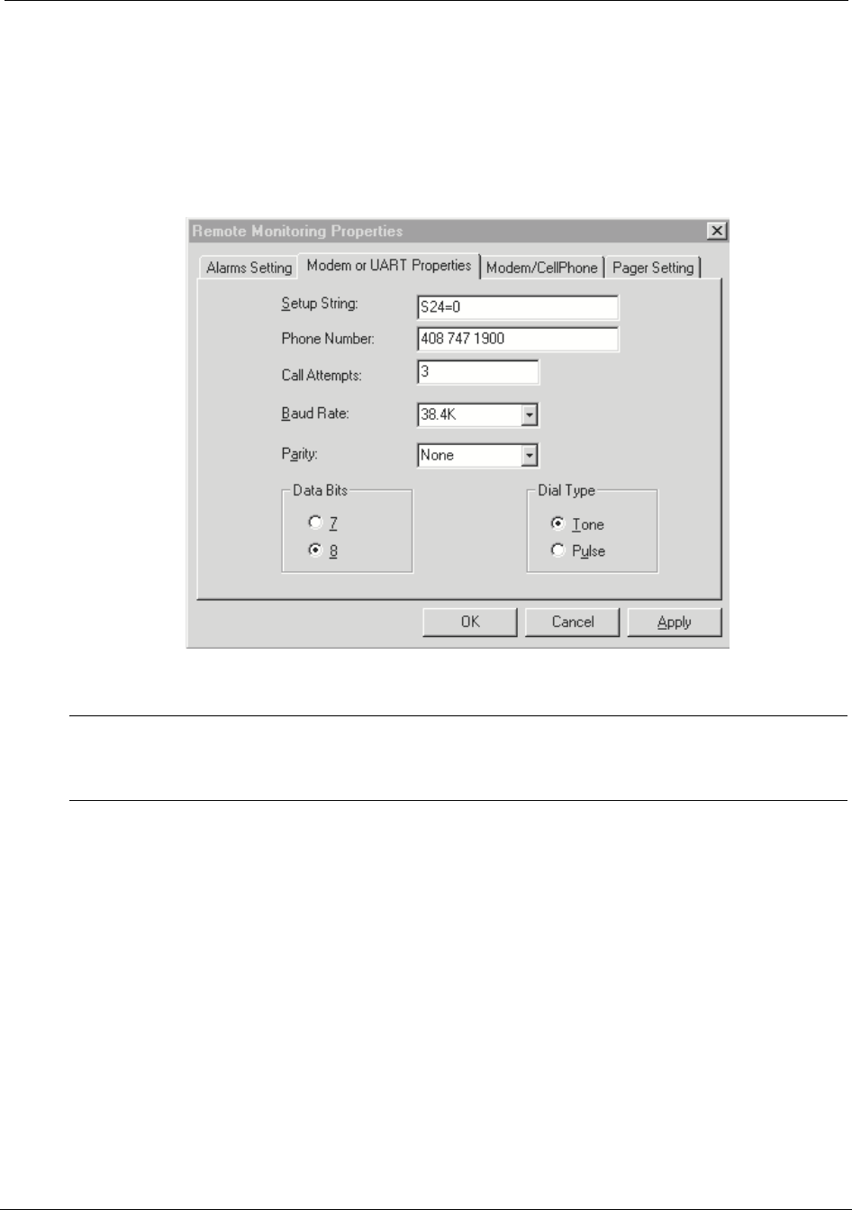
Configuring the Repeater Reference Manual
5-54 RTI Confidential 550-1300-01 Rev C
5.11.2 Modem Properties Tab
To define proper settings for the repeater's internal modem or UART, use the Modem
Properties tab (see Figure 5-42).
Figure 5-42 Remote Monitoring Properties Screen
NOTE: The Craft software uses the values for Setup String, Phone Number, and Call
Attempts, only if you are using the RepeaterNet Network Management System. If you do
not have an NMS, skip to Section 5.11.4, “Pager Setting Tab” on page 5-57.
To define modem properties, use the following procedure:
1. Select Remote Monitoring Properties from the Configuration menu in the Main Con-
trol Screen.
The Remote Monitoring Properties screen opens (see Figure 5-42).
RT221110

Reference Manual Configuring the Repeater
550-1300-01 Rev C RTI Confidential 5-55
2. Click the Modem Properties tab.
If you are using RepeaterNet NMS, verify the Setup String, Phone Number and Call
Attempts.
NOTE: Use the Setup String defaults.
•Setup String configures a modem or UART and is automatically set when a
remote monitoring device is chosen.
•The Phone Number is the phone number of a remote computer that the repeater
calls.
•Call Attempts defines the number of calls the repeater attempts when reporting
an alarm.
NOTE: A “Call Attempts” value of zero (0) disables calling.
3. Set the Baud Rate for the modem. (Leave at default.)
The Baud Rate is the communication speed between the modem and the cell phone.
This speed must be greater than 2400. The modem automatically adjusts the Baud
Rate downward, when necessary.
4. Verify Parity is None.
5. Verify Data Bits is 8.
6. Verify Dial Type is Tone.
7. Click the Apply or OK button.
•The Apply button sets the modem properties and keeps the Remote Monitoring
Properties screen open.
•The OK button sets the modem properties and closes the Remote Monitoring
Properties screen.
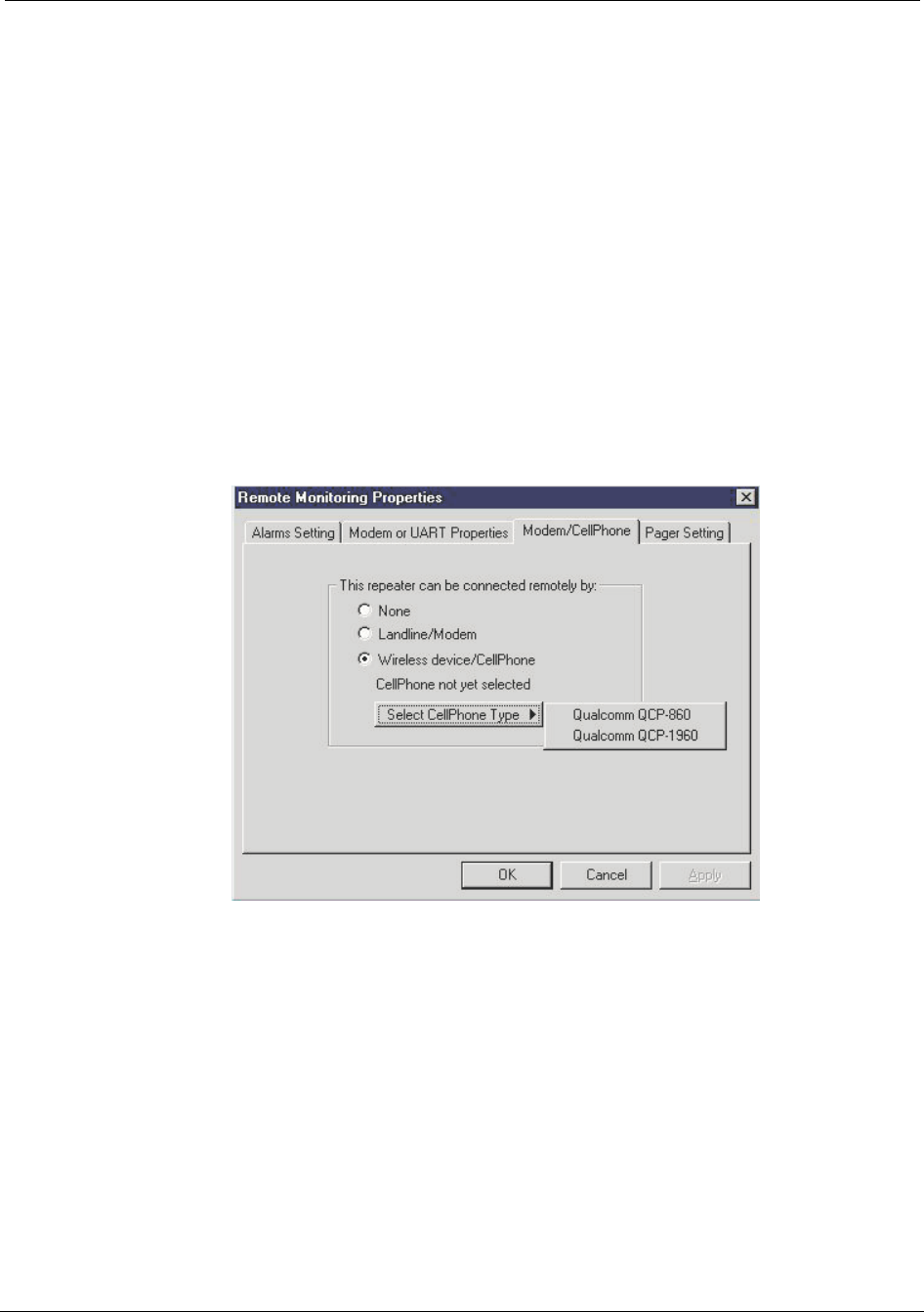
Configuring the Repeater Reference Manual
5-56 RTI Confidential 550-1300-01 Rev C
5.11.3 Modem/Cell Phone Properties Tab
Modem/Cell phone properties define the type of device to be used for remote monitor-
ing. Repeaters may be monitored via:
•Landline
•CDMA phone
Select the radio button which matches the type of remote monitoring device attached to
the repeater.
•None - No remote monitoring capability
•Landline/modem - Hardwire Landline (POTS)
•Wireless Device - CDMA phone
Figure 5-43 Remote Properties Screen
RT330101

Reference Manual Configuring the Repeater
550-1300-01 Rev C RTI Confidential 5-57
5.11.4 Pager Setting Tab
The Pager Setting tab allows the Repeater to dial a pager when an alarm occurs. It also
assigns a specified minimum severity level to the alarm. Table 5-3 describes the Alarm
Severity settings.
NOTE: Use the most basic service for the pager.
RepeaterNet generates a page if the summary alarm severity is greater than or equal to
the selected Minimum Severity setting. The page format consists of the repeater number,
followed by the severity level. For example:
1920-2
where 1920 is the repeater number and 2 is the severity level of the alarm.
If RepeaterNet detects a change in the current alarm severity, it does the following:
•If you set the Minimum Severity to Major, the RepeaterNet software generates a
page with a severity of 2.
•If the RepeaterNet software detects a Critical alarm, it generates a new page with
a severity of 3.
•If you clear the Major alarm, but the Critical alarm remains, the RepeaterNet soft-
ware generates a new page with a severity level of 1, indicating that the Critical
alarm remains.
•If you then clear the Critical alarm, the RepeaterNet software generates a page
with a severity of 0.
•If the RepeaterNet software detects a Minor or Event alarm, it does not generate a
page.
NOTE: Repeater pager function dials a specified number. When the remote connection
answers it goes off hook. The repeater outputs the alarm and disconnects. It is a one-way
communication.
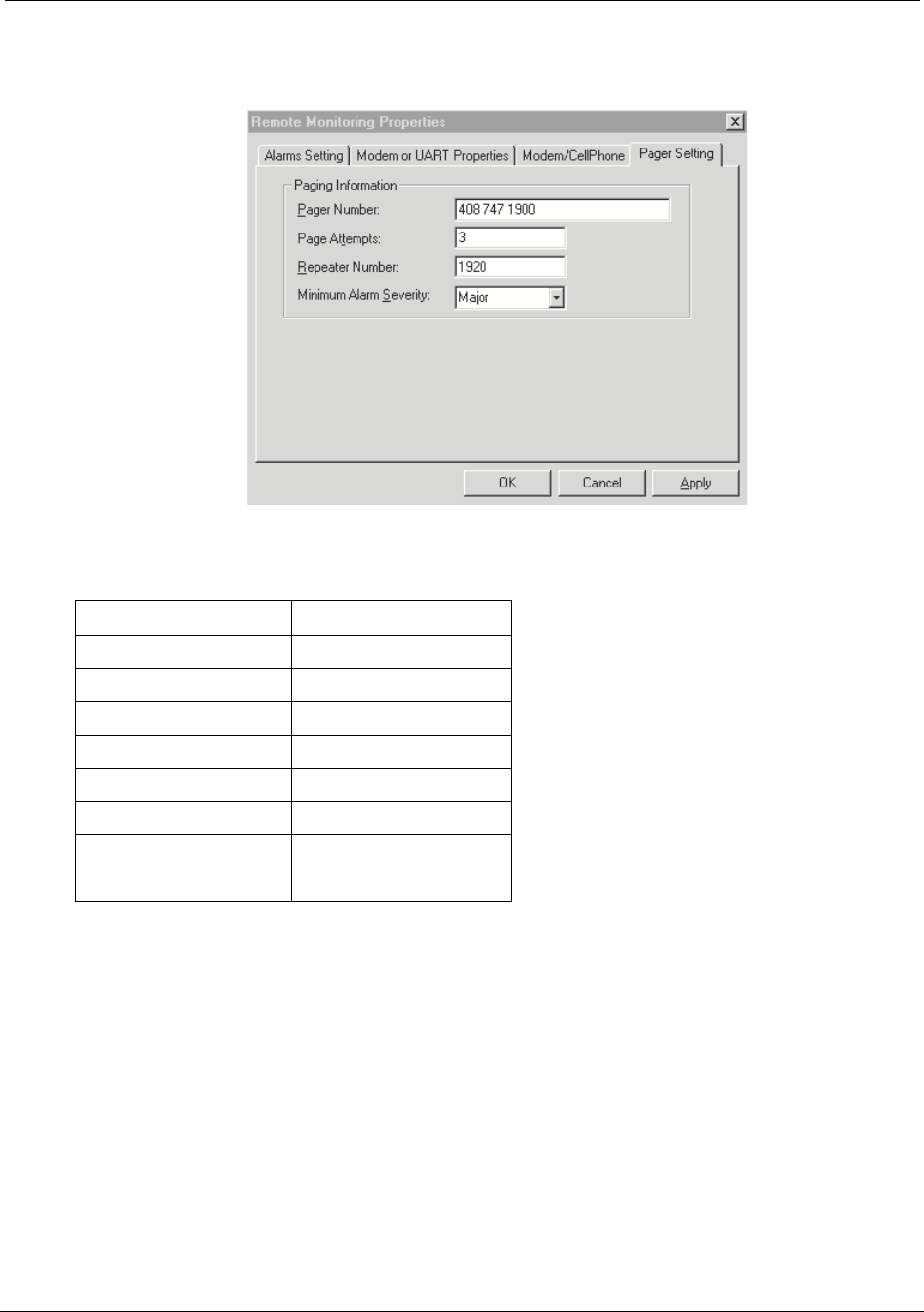
Configuring the Repeater Reference Manual
5-58 RTI Confidential 550-1300-01 Rev C
Figure 5-44 Remote Monitoring Properties, Pager Settings
Table 5-3 Alarm Severity Numbers
Use the following procedure to set a pager.
1. Click on the Pager Setting tab of the Remote Monitoring Properties screen.
2. Enter the Pager Number.
The Pager Number is the phone number the repeater will dial. This phone number
must include the networking access number (example 9), 1 and the area code (if
needed).
Normally, several commas must follow the phone number. Each comma generates a
delay of one second. Generally, a pager company requires about three seconds to pick up
the line, and allows a maximum of five seconds before they drop the connection.
Alarm Type Severity Number
No Alarms 0
Critical Alarm 1
Major Alarm 2
Critical + Major 3
Minor Alarm 4
Critical + Minor 5
Major + Minor 6
Critical + Major + Minor 7
RT221108

Reference Manual Configuring the Repeater
550-1300-01 Rev C RTI Confidential 5-59
A good delay setting is five seconds - that is, add five commas. For example:
9 1 408 555-1212,,,,,
NOTE: RepeaterNet ignores any characters used for clarity, such as spaces, dashes, and
parentheses.
3. Enter the number of times RepeaterNet should attempt to dial the pager number
(Page Attempts). The repeater will page the number of times specified.
Example: If attempts is set to one, the repeater will page once, if set to three, then three
attempts will be made.
NOTE: A value of zero (0) in this field disables paging.
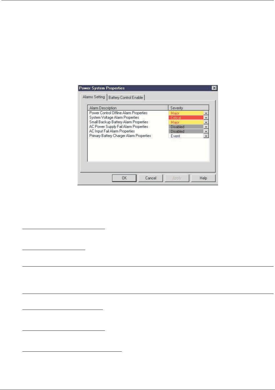
Configuring the Repeater Reference Manual
5-60 RTI Confidential 550-1300-01 Rev C
5.12 Power System Properties
From the Configuration menu in the Main Control screen, select Power System.
The Power System Properties screen opens (see Figure 5-45). This screen provides access
to initial configuration settings for the power subsystem.
Figure 5-45 Power System Properties Screen, Alarm Setting
Use the Alarm Setting tab to redefine alarm severity for the power systems.
The Alarm Setting tab sets the alarm severity for the following alarms:
Power Control Offline Alarm - The ACU cannot communicate with the power control
module.
System Voltage Alarm - The internal system voltage of the repeater is out of it’s specified
range.
NOTE: The internal battery does not provide power for RF components. The repeater
cannot provide RF coverage during a power failure without a Back-up Power System
(BUPS).
Small Backup Battery Alarm - Indicates the small backup battery (located on the door of
the repeater) has failed the load test and needs to be replaced.
Power Supply AC Fail Alarm - The AC/DC converter is no longer providing DC current.
Disable this alarm in DC power systems.
Power Supply AC Input Fail Alarm - The input AC voltage is too low (or off). Disable this
alarm in DC powered systems.
RT286106
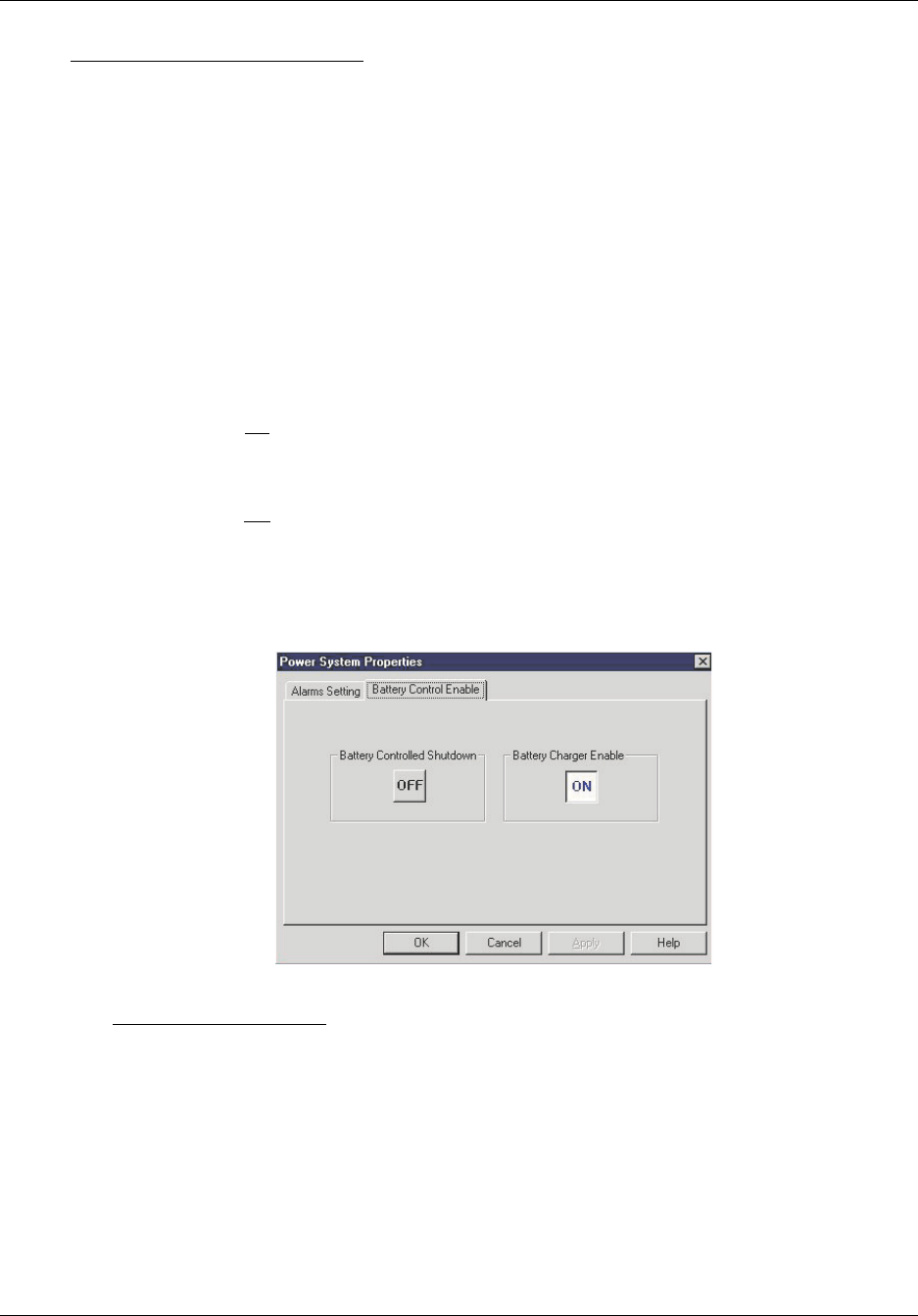
Reference Manual Configuring the Repeater
550-1300-01 Rev C RTI Confidential 5-61
Primary Battery Charge Alarm - The internal BUPS cannot charge the large external bat-
teries. Disable this alarm if the Primary Battery Charger option is not installed.
1. Click the down-arrow next to an Alarm field to select a new alarm severity:
2. Click the Apply or OK button.
•The Apply button changes the alarm severity setting and keeps the Power System
Properties screen open.
•The OK button changes the alarm severity setting and closes the Power System
Properties screen.
Use the Battery Alarm Control Enable Tab to turn on or off the battery backup features.
1. The battery controlled shutdown affects how the repeater turns off due to a power
failure.
When turned on, the repeater will use the small backup battery to power the ACU
and remote monitoring kit during a power failure. This is the normal setting for the
repeater.
When turned off, the battery will not be discharged. This position is intended for use
while the repeater is being stored and not to be used for normal operations.
Figure 5-46 Power System Properties Screen, Battery Control Enable
2. Battery Charge Enable - The button turns on and off the primary battery charger
function for the externally mounted batteries.
RT330103

Configuring the Repeater Reference Manual
5-62 RTI Confidential 550-1300-01 Rev C
5.13 Back-up Power System (BUPS) Properties
The BUPS Properties screen provides the configuration settings of alarms for the optional
Back-up Power Supply (BUPS), which is external to the repeater.
1. From the menu bar in the Main Control screen, select Configuration -> BUPS.
The BUPS Properties screen opens (see Figure 5-47).
2. Use the Alarm Setting tab to redefine an alarm severity for the back-up power sys-
tems.
The Alarm Setting tab sets the alarm severity for the following alarms:
Ext. BUPS AC (Mains) Fail Alarm - Indicates that the input power to the BUPS has failed.
Depending on which BUPS model is installed at the repeater site, the BUPS will then pro-
vide 40 or 80 amp-hours of backup power for the repeater, before shutdown. The AC
source powers the charger.
Ext. BUPS Low (Float) Battery Alarm Properties - Indicates that the battery voltage for the
BUPS is below operating tolerances, and the BUPS cannot power the repeater.
Ext. BUPS High (Float) Battery Alarm Properties - Indicates that the battery voltage of the
BUPS is above operating tolerances, and the BUPS cannot power the repeater.
Ext. BUPS Charger (Rectifier) Fail Alarm - Indicates that the internal charger of the BUPS
has failed, and the BUPS is unable to recharge its batteries.
Ext. BUPS Summary (Load/Battery) Alarm - Indicates that one or more of the BUPS
alarms have triggered.
Ext. BUPS Tamper (Optional) Alarm - Indicates that the door of the BUPS is open. (Not
currently used.)
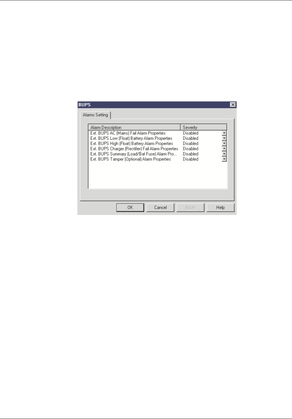
Reference Manual Configuring the Repeater
550-1300-01 Rev C RTI Confidential 5-63
3. Click the down-arrow next to an Alarm field to select a new alarm severity:
4. Click the Apply or OK button.
•The Apply button changes the alarm severity setting and keeps the BUPS Proper-
ties screen open.
•The OK button changes the alarm severity setting and closes the BUPS Properties
screen.
Figure 5-47 BUPS Properties Screen
RT221105

Configuring the Repeater Reference Manual
5-64 RTI Confidential 550-1300-01 Rev C
5.14 RepeaterNet Menu Commands
This section describes commands that you can run from the menu bar in the RepeaterNet
Main Control screen.
5.14.1 File Menu - Craft
From the Main Control screen, open the File menu. Figure 5-48 shows the RepeaterNet
commands in this menu.
Figure 5-48 Craft, File Menu
Download Properties
Use the Download Properties command to download a previously saved configuration
file or a master configuration file used on several repeaters in a network:
•Restore repeater configuration settings. Restoring overwrites existing configura-
tion settings. Use this option if you previously used the Upload Properties com-
mand to store repeater configuration settings.
Use the following procedure to download settings to a repeater, from a repeater configu-
ration file.
1. From the Craft Main Control File menu, select Download Properties.
2. Select the appropriate file to download to the repeater. (See Figure 5-49).
Select open.
3. Click on the Open button to proceed with the download.
The writing properties to repeater dialog box will open. Progress bar indicates status
of download. When the download is complete, a confirmation message box displays.
RT131139
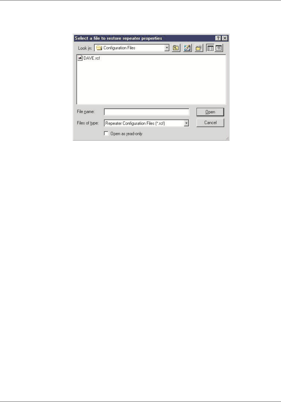
Reference Manual Configuring the Repeater
550-1300-01 Rev C RTI Confidential 5-65
Figure 5-49 Downloading Repeater Configuration Files
RT233103
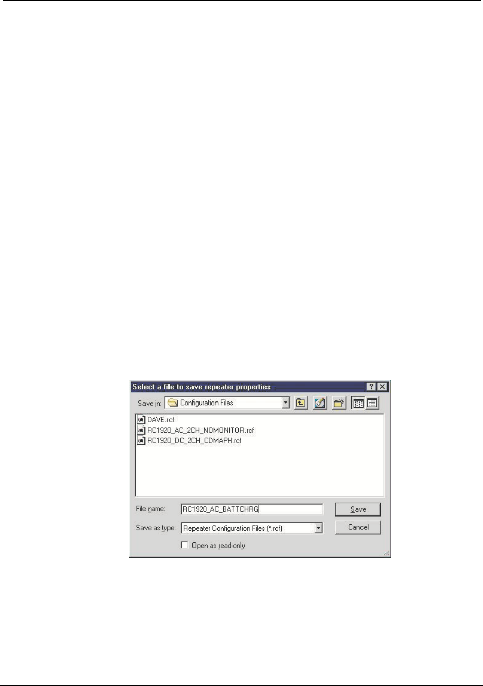
Configuring the Repeater Reference Manual
5-66 RTI Confidential 550-1300-01 Rev C
Upload Properties
RepeaterNet stores system settings, such as alarm severities, in a repeater configuration
(.rcf) file. You can upload all settings from one repeater, and download these settings to
additional repeaters in a network. You also can use existing configuration files to config-
ure a replacement unit.
To upload the configuration from repeater, use the Upload Properties command. You can
then use the Download Properties command to copy the configuration to individual
repeaters in the CDMA network.
Use the following procedure to upload system settings, and to create repeater configura-
tion files.
1. Select File -> Upload Properties.
2. Select a File to Save Repeater Properties To dialog box opens (see Figure 5-50).
3. Enter a name for the file without a file extension.
Craft automatically adds a .rcf extension to the file name; for example:
Filename.rcf
4. Click Save to initiate the upload.
When the upload is complete, a message box displays.
5. Click the OK button.
6. Save a copy of the repeater configuration file onto a floppy disk for safe keeping.
Figure 5-50 Saving Repeater Properties to a File
RT337102
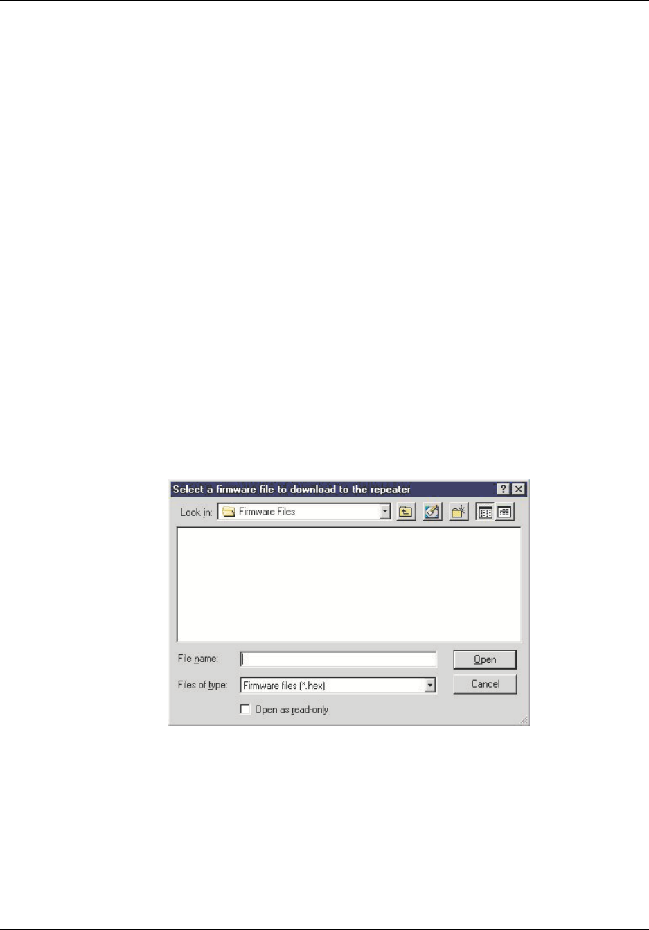
Reference Manual Configuring the Repeater
550-1300-01 Rev C RTI Confidential 5-67
Update Repeater Firmware
Use the Update Repeater Firmware command to install a firmware upgrade.
Firmware updates include:
•A detailed description of the update
•A CD containing the firmware update
•Installation instructions
Direct any questions concerning the firmware upgrade to the Repeater Technologies Cus-
tomer Service Department.
To install a firmware upgrade:
1. Read the documentation provided with the firmware upgrade.
2. Connect to the repeater to be upgraded.
3. Insert the upgrade CD into the computer's CD-rom drive.
4. From the menu bar in the Main Control screen, select File -> Update Repeater Firm-
ware.
A file selection screen displays (see Figure 5-51).
Figure 5-51 Selecting File Names for Saving Firmware Updates
5. Select the new firmware file and click the open button.
6. There will be displayed a status bar that indicates how much time is left for the
upgrade. (Figure 5-52)
RT233104
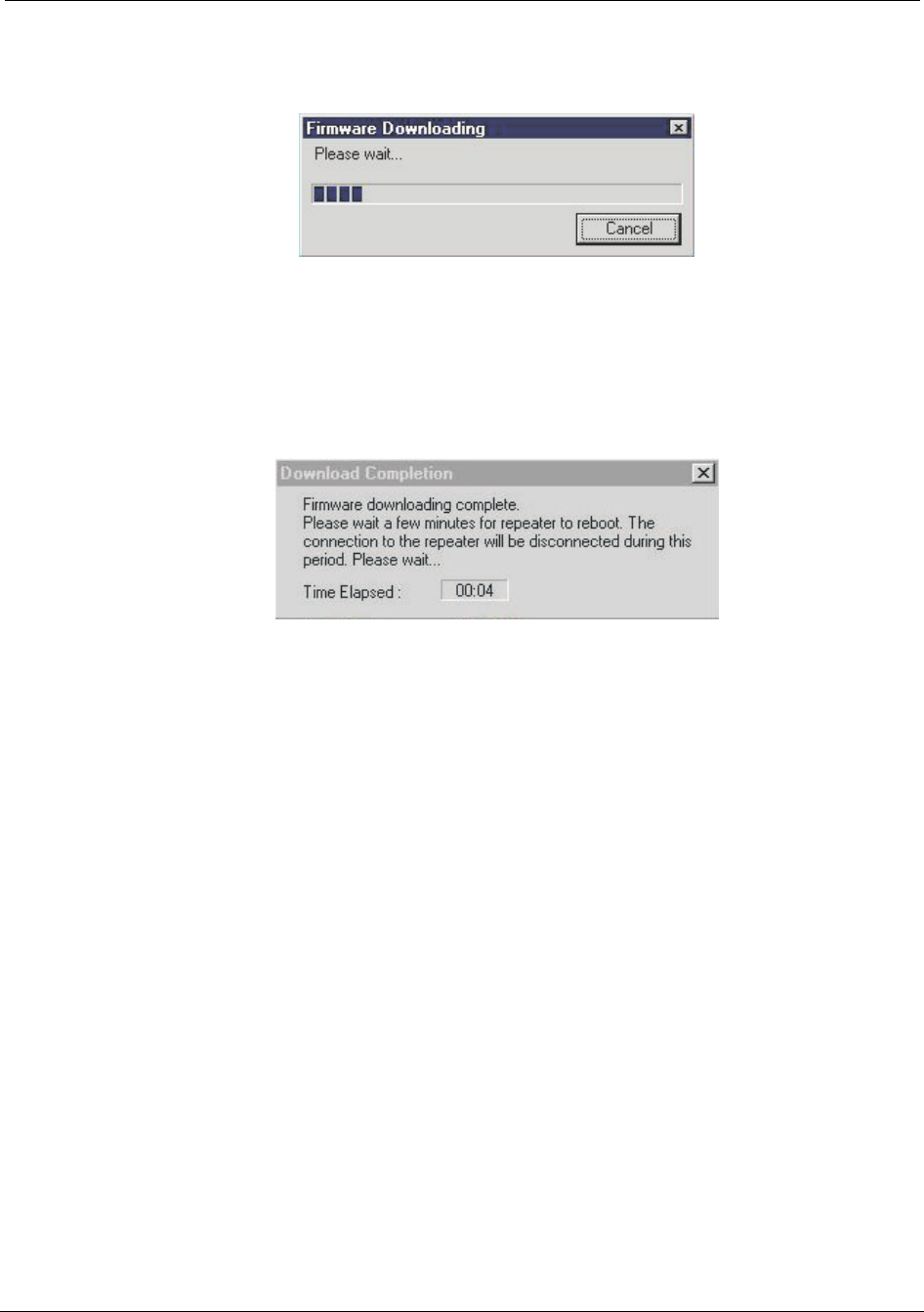
Configuring the Repeater Reference Manual
5-68 RTI Confidential 550-1300-01 Rev C
Figure 5-52 Firmware Download Window
7. When the firmware upgrade is complete the repeater will reboot. Craft will display
Figure 5-53.
Figure 5-53 Download Completion Window
8. When all is complete Craft will display the dialog box stating that the upgrade is
completed. Click okay.
Exit
The Exit command ends an active session in the RepeaterNet software.
RT233106
RT233105

Reference Manual Configuring the Repeater
550-1300-01 Rev C RTI Confidential 5-69
5.14.2 System Menu - Craft
This section describes commands in the System menu, as shown in Figure 5-54.
Figure 5-54 Craft, System Menu Pull-down Menu
Properties
Select Properties from the System menu.
The System Properties screen opens.
System Tab
The System tab includes data fields for storing site-specific information (see Figure 5-55):
•The system name (name of the repeater)
•Brief site information (such as network name, or a city location)
•The repeater phone number, if the repeater has a modem option
•The system time and date
Entering summary data (on the System tab) is optional, but RTI recommends entering
this data.
To record system data:
1. Type the required information in each data field:
•System (Repeater) Name - up to 12 characters
•During automatic reporting, the repeater name displays in the title bar of the
Main Control screen, identifying the selected repeater.
•Site Information, Field 1 - up to 14 characters. Typically, identifies the cell phone
network (optional)
•Site Information, Field 2 - up to 14 characters. Typically, identifies the repeater
location (optional).
•Site Phone Number - phone number of the repeater, up to 12 characters (optional)
RT233107
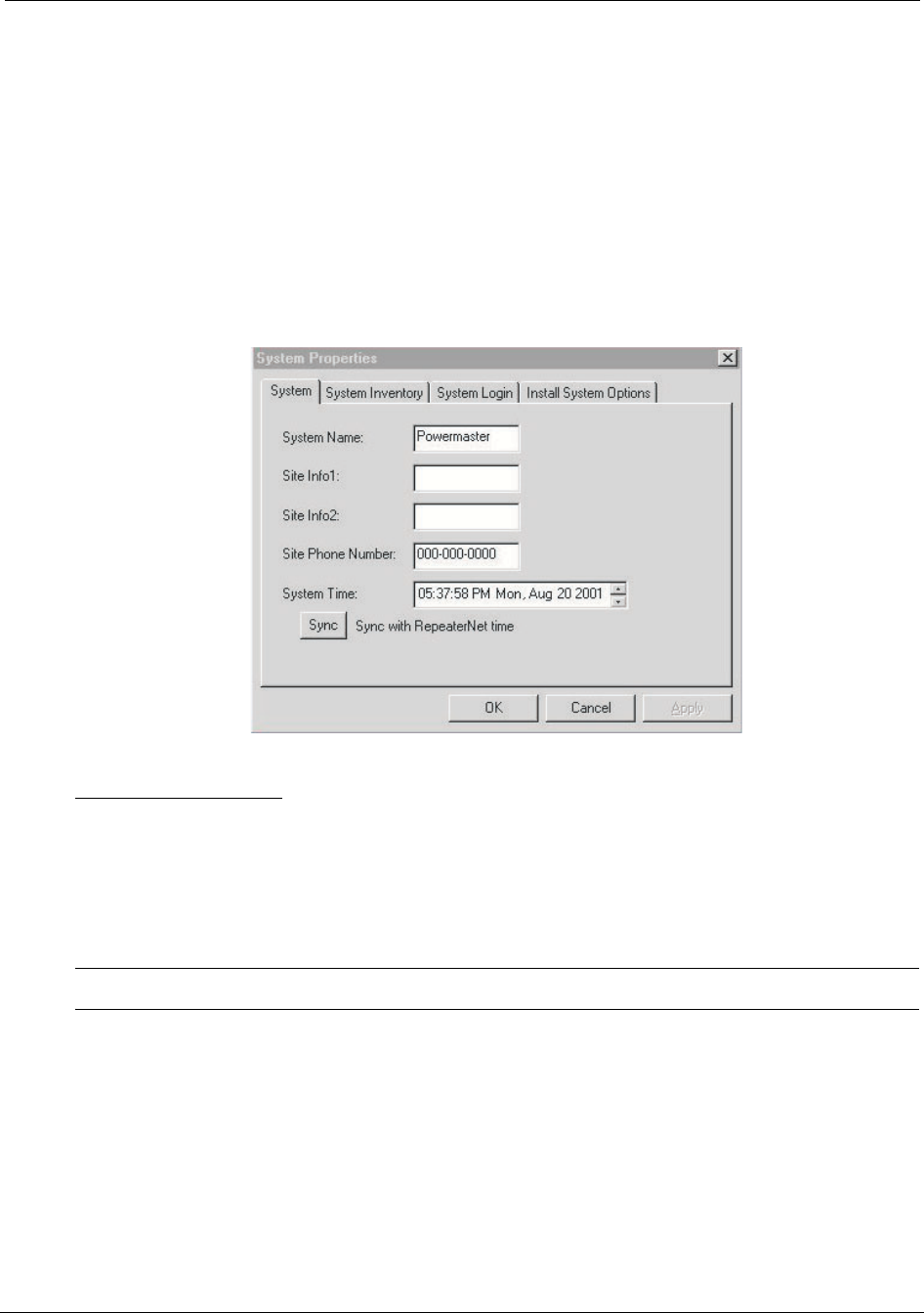
Configuring the Repeater Reference Manual
5-70 RTI Confidential 550-1300-01 Rev C
•System Time - can be updated manually by clicking on the up/down buttons and
the field entries (hour, minute, second, am/pm, month, day, and year), or by click-
ing on the sync button synchronized with the computer’s time.
2. Click the Apply or OK button.
•The Apply button sets the system properties and keeps the System Properties
screen open.
•The OK button sets the system properties and closes the System Properties screen.
Figure 5-55 System Properties Screen, System Tab
System Inventory Tab
The System Inventory tab (see Figure 5-56) displays information about the repeater to
which the PC or laptop is connected.
After you successfully login, RepeaterNet reads this information directly from the
repeater.
NOTE: You cannot edit data in any field of this tab.
Table 5-4 summarizes the data displayed in the information-only fields of this tab.
RT233108
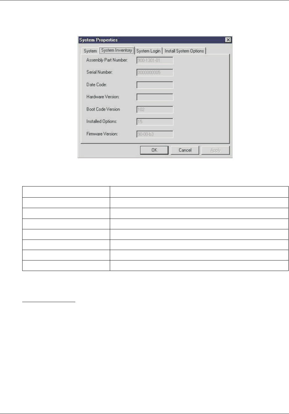
Reference Manual Configuring the Repeater
550-1300-01 Rev C RTI Confidential 5-71
Figure 5-56 System Properties Screen, System Inventory Tab
Table 5-4 Description of System Inventory Fields
System Login Tab
The System Login tab (see Figure 5-57) includes fields to do the following:
•Edit login IDs
•Edit passwords
•Configure the Auto-logout function
In the Auto-Logout Inactivity Time field, define how long RepeaterNet should wait, dur-
ing a period of inactivity, before it terminates a session.
Field Name Description
Assembly Part Number The part number of the repeater (for example: 900-1300-01)
Serial Number The 9-digit serial number of the repeater
Date Code The date when the repeater was built
Hardware Version The repeater hardware revision (such as Rev. A)
Boot Code Version The version number of the boot code installed in the repeater.
Installed Options Optional internal equipment in the repeater (such as cell phone)
Firmware Version The version number of the firmware installed in the repeater
RT233109
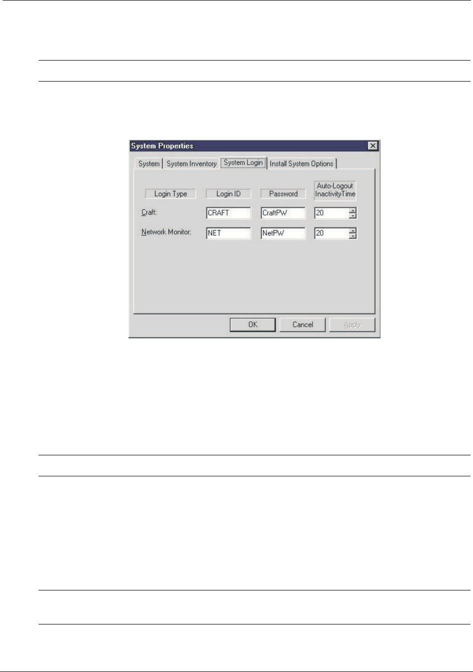
Configuring the Repeater Reference Manual
5-72 RTI Confidential 550-1300-01 Rev C
You can define a separate time interval in minutes, between 1 and 60, for each access
level. If you enter a zero in a time field, this feature becomes disabled.
NOTE: When the repeater is part of a network, the time field must be zero(0).
Figure 5-57 System Properties Screen, System Login Tab
To change a login ID or password:
1. Login to the repeater (as an administrator).
2. Select Properties from the System menu.
3. Click the System Login tab.
4. Type the new login ID or password into the appropriate fields.
NOTE: The login ID and the password must each consist of six or fewer characters.
5. Write down the login Ids and passwords, and secure them in a safe place.
6. Click the Apply or OK button to set the new information.
•The Apply button sets the login information and keeps the System Properties
screen open.
•The OK button sets the login information and closes the System Properties screen.
7. Notify affected operators about the ID and password changes.
NOTE: When the repeater is networked, only the network monitor needs to reside in the
NMS Database.
RT233113

Reference Manual Configuring the Repeater
550-1300-01 Rev C RTI Confidential 5-73
Initial System Install
The Install Systems Option Tab allows a user to enable optional features to the repeater
given the proper options password.
•Secondary Channel - Enables the second channel in the repeater
•Diversity - Enables the diversity option
•Battery Charger - Enables the internal BUPS feature to charge external batteries
•Monitoring Kit - Enables the remote monitoring (cell phone, landline) options.
NOTE: Without the proper passwords a user will not be able to install these options.
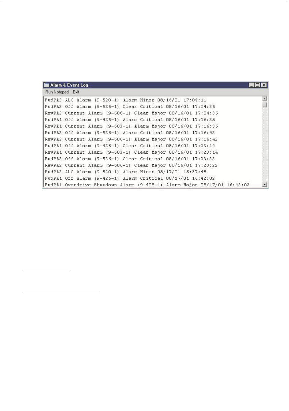
Configuring the Repeater Reference Manual
5-74 RTI Confidential 550-1300-01 Rev C
Alarm and Event Log
Open the Alarm and Event Log from the System menu (Figure 5-58), to view the alarm
and event history. This log dynamically updates during viewing. Use the clear option to
delete all alarm entries in the log.
Figure 5-58 Alarm and Event Log
Line entries in the Alarm and Event Log are organized as follows:
1. Subsystem affected by an alarm or event
2. Alarm severity
3. Date and time stamp
You can use Notepad to print or save Alarm and Event Log entries.
Refresh Alarms - By clicking on the refresh Alarms pull-down menu Craft will obtain the
latest state of the alarms in the repeater.
Test Alarm Dialout Setup - By clicking on the Test Alarm Dialout Setup menu item
(Figure 5-59) appears. This window allows a user to create an artificial alarm and have
this alarm reported to the NMS. This is a useful tool in verifying NMS (Network Manage-
ment System) dialout capabilities.
RT233111
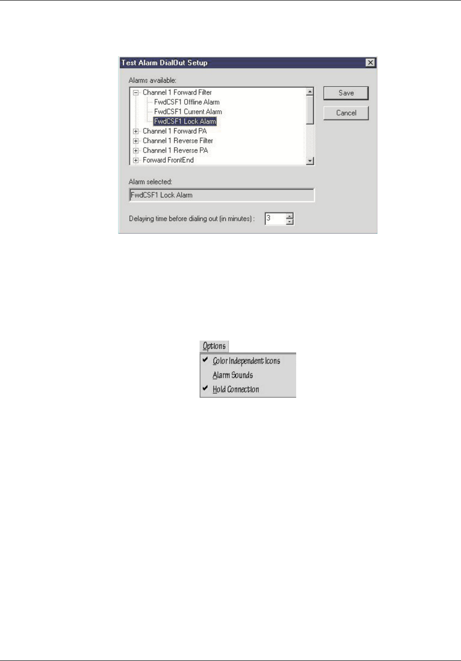
Reference Manual Configuring the Repeater
550-1300-01 Rev C RTI Confidential 5-75
Figure 5-59 Test Alarm DialOut Setup
5.14.3 Options Menu - Craft
Figure 5-60 shows the RepeaterNet commands in the Options menu.
Figure 5-60 Craft, Options Menu
RT233112
RT249103

Configuring the Repeater Reference Manual
5-76 RTI Confidential 550-1300-01 Rev C
Color Independent Icons
Color Independent Icons are special graphic indicators, designed to assist operators who
are unable to distinguish colors. As part of the alarm reporting system, Color Indepen-
dent Icons display on the Main Control screen for a Critical, Major, or Minor alarm.
By default, the Color Independent Icons feature is Off.
From the Main Control screen menu bar, select Options -> Color Independent Icons, to
turn On this feature. Table 5-5 describes each of the color-independent icons.
Table 5-5 Description of Color Independent Icons
Alarm Sounds
The Alarm Sounds feature allows an intermittent audible alarm to activate, when a sub-
system triggers an alarm.
By default, the Alarm Sounds feature is Off.
From the Main Control screen menu bar, select Options -> Alarm Sounds, to turn On this
feature.
To silence an audible alarm, either click a subsystem icon (to open the Status screen), or
clear the alarm.
Hold Connection
The hold connection option causes Craft to re-dial the repeater 5 times if the phone line
connection is lost.
Alarm Type Color Independent icon Symbol
Critical X through the subsystem icon X
Major Back slash (\) through the subsystem icon. \
Minor Dotted-line back slash through subsystem icon \ (Dotted)
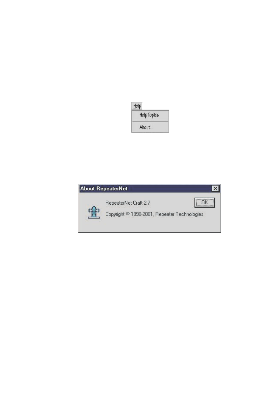
Reference Manual Configuring the Repeater
550-1300-01 Rev C RTI Confidential 5-77
5.14.4 Help Menu - Craft
RepeaterNet on-line help provides quick access to information related to the operation of
the repeater. Figure 5-61 shows the Help menu.
•To open RepeaterNet Help, select Help -> Help Topics.
•To learn about the version of Craft, installed, select About… from the Help menu
of any program window.
Figure 5-61 Craft, Help Menu
Figure 5-62 shows a typical about screen. Clicking on okay makes the screen go away.
Figure 5-62 About Screen
RT249104
RT286107

Configuring the Repeater Reference Manual
5-78 RTI Confidential 550-1300-01 Rev C

550-1300-01 Rev C RTI Confidential 6-1
6
Connecting External Alarms and
Relays
6.0 Overview
This chapter describes how to connect external alarms and relays.
•Use the connector labeled UPS to wire alarms from the Back-Up Power Supply
(BUPS) to the repeater.
•Use the connector labeled IN/OUT for digital inputs to custom external alarms,
or for digital outputs to remotely-controlled devices at the repeater site.
•The connector labeled USER RELAY provides two independently-controlled dry
contact relays, each with standard 1C contact sets. RepeaterNet software can use
these relays to control devices at the repeater site.
•The connector labeled ALARM RELAY provides three independent relays, each
with contact sets in standard 1C form (SPDT). Each relay is driven by specific
summary alarms that the repeater generates. For example, one relay might acti-
vate whenever the repeater generates a critical alarm. Similarly, a second relay
might activate whenever the repeater generates a major alarm, and a third might
activate on a minor alarm
Table 6-1 lists all of the input and output connections, pin numbers, and functions, for all
repeater's external alarm connectors.
NOTE: The ground reference for IN/OUT and BUPS inputs and/or outputs is the chas-
sis ground terminal.

Connecting External Alarms and Relays Reference Manual
6-2 RTI Confidential 550-1300-01 Rev C
Table 6-1 Input/Output Pin Descriptions
Connector Pin # Signal Name Function
UPS 1 External Tamper Input Secondary Door Open
2 BUPS Tamper Input External Input Alarm
3 BUPS AC Fail Input External Input Alarm
4 BUPS Low Battery Voltage Input External Input Alarm
5 BUPS High Battery Voltage Input External Input Alarm
6 BUPS Charger Failure Input External Input Alarm
7 BUPS Summary External Input Alarm
8GND GND
In/Out 1 Digital Output 1 Low Active
2 Digital Output 2 Low Active
3 DC Voltage Input (Ext) 0-60 V Input Voltage
4 Digital Input 1 External Input Alarm
5 Digital Input 2 External Input Alarm
6 Digital Input 3 External Input Alarm
7 Digital Input 4 External Input Alarm
User Relay 1 User 1 NO Normally Open
2 User 1 NC Normally Closed
3 User 1 COM Common
4 User 2 NO Normally Open
5 User 2 NC Normally Closed
6 User 2 COM Common
Alarm Relay 1 Critical Relay NO Normally Open
2 Critical Relay NC Normally Closed
3 Critical Relay COM Common
4 Major Relay NO Normally Open
5 Major Relay NC Normally Closed
6 Major Relay COM Common
7 Minor Relay NO Normally Open
8 Minor Relay NC Normally Closed
9 Minor Relay COM Common
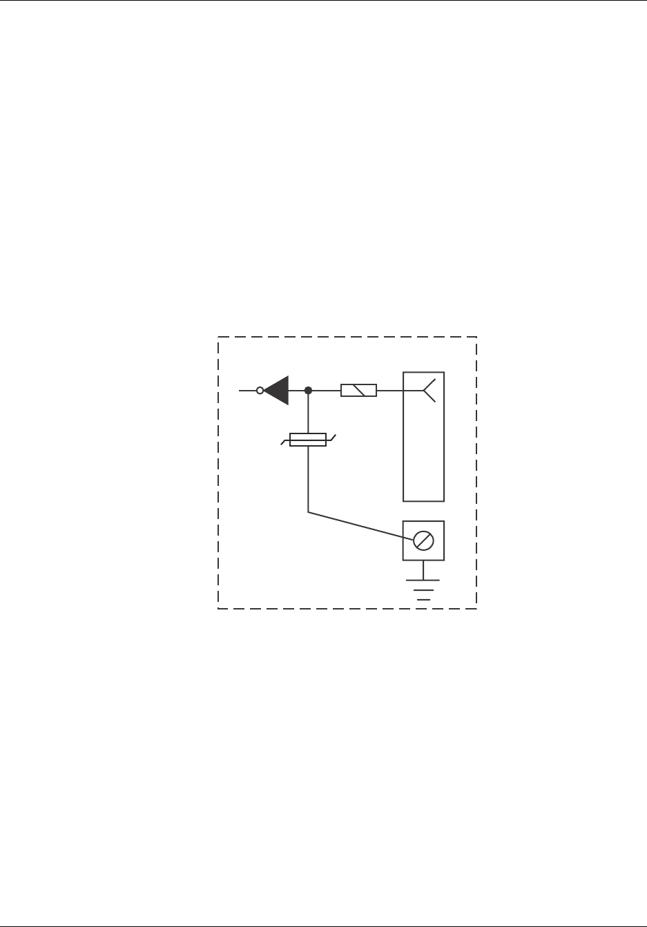
Reference Manual Connecting External Alarms and Relays
550-1300-01 Rev C RTI Confidential 6-3
6.1 Back-up Power System (BUPS) Monitoring
Refer to section 3.3 for information on connecting external alarms from a BUPS.
6.2 User Controlled Inputs and Outputs
6.2.1 Digital Inputs
You can use the four digital inputs to monitor equipment or events that are external to the
repeater. You can control and process these external alarms through the RepeaterNet soft-
ware.
Figure 6-1 shows the basic circuit for the external alarm inputs. The digital inputs are
accessible through the IN/OUT connector on the Line Entry Module.
Figure 6-1 Digital Input Circuit - Typical
One of the most common external alarms, at a base station or a repeater site, is the failure
of a tower hazard warning light. This light, used for warning aircraft of the existence of a
tower, must be replaced immediately if it fails. Figure 6-2 shows how the external digital
alarm inputs can monitor a tower light.
4
RT213108
Repeater
Varistor
100 Ohm
(+)
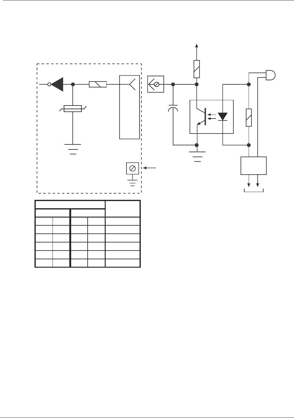
Connecting External Alarms and Relays Reference Manual
6-4 RTI Confidential 550-1300-01 Rev C
Figure 6-2 Monitoring a Tower Hazard Light
Do not exceed the following specifications when connecting digital inputs:
6.2.2 Analog Input
The repeater has one analog input, to monitor an external DC voltage. The monitoring
range is from 0 to 60 volts, with a resolution of 250 mV.
Input Voltage for Logic 0 <0.3 Volts
Input Voltage for Logic 1 >4.0 Volts
Maximum Input Voltage 5.0 Volts
Minimum Input Voltage 0.0 Volts
Maximum Input Current 8 mA
200
250
5000.5 20W 1.0 10W
100
150
LAMP SIZE
(WATTS)
50
1.0 10W 1.8 10W
1.2 10W 2.7 5W
1.5 5W 3.3 5W
2.2 5W 4.7 5W
3.9 2W 8.2 2W
115 VAC
VALUE FOR R1 (Ohms)
220 VAC
4
RT213109
Repeater
Varistor
100 Ohm
(+)
Digital Alarm Input No. 1
Chassis Ground Terminal
115 - 220 VAC 47 - 63 Hz
Tower
Warning
Light
Lamp
Control
R1
+5 VDC (MAX)
1k
0.25 Watt
+
1000mF
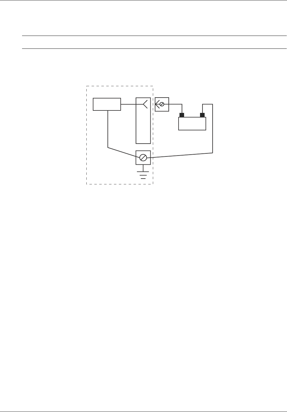
Reference Manual Connecting External Alarms and Relays
550-1300-01 Rev C RTI Confidential 6-5
1. Connect the positive lead to pin 3 of the In/Out connector as shown in Figure 6-3.
2. Connect the negative lead to the repeater's chassis-ground terminal.
CAUTION: Do not allow any input to exceed the 60-Volt limit.
Figure 6-3 Typical DC Monitoring
6.2.3 Digital Outputs
The repeater includes two digital outputs, each with one lead for an open-collector-tran-
sister. When the RepeaterNet software sets one of these digital output switches to On, the
repeater sends a voltage of zero with 20 mA current.
Figure 6-4 depicts the output circuitry of each user-controlled digital output.
VOL 0.6 V maximum
lOL 20 mA
VOH 4.20 V minimum
lOH -3 mA
3
RT213110
Repeater
(+)
A/D
Converter
DC Voltage
+-
In/Out Connector
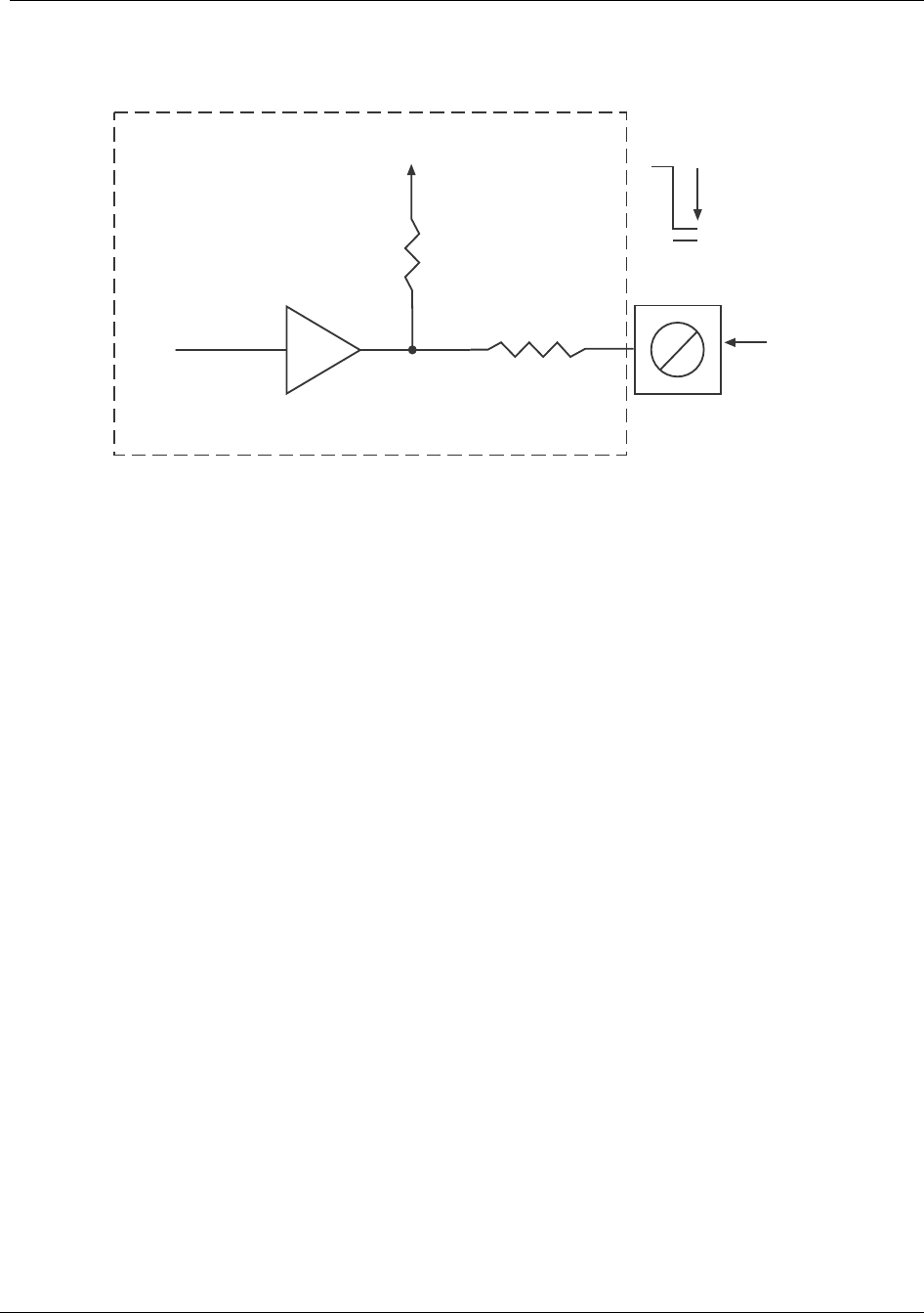
Connecting External Alarms and Relays Reference Manual
6-6 RTI Confidential 550-1300-01 Rev C
Figure 6-4 User-Controlled Digital Output - Typical
Figure 6-5 shows a typical application for a digital output.
Refer to the Alarm Control Status Screen in Chapter 5, Configuring the Repeater, for
instructions about activating digital outputs.
100 Ohms
35-120
k Ohms
VCC
Connector
In/Out
Pin 1 or 2
RT212116
VCC
1.0V
0V
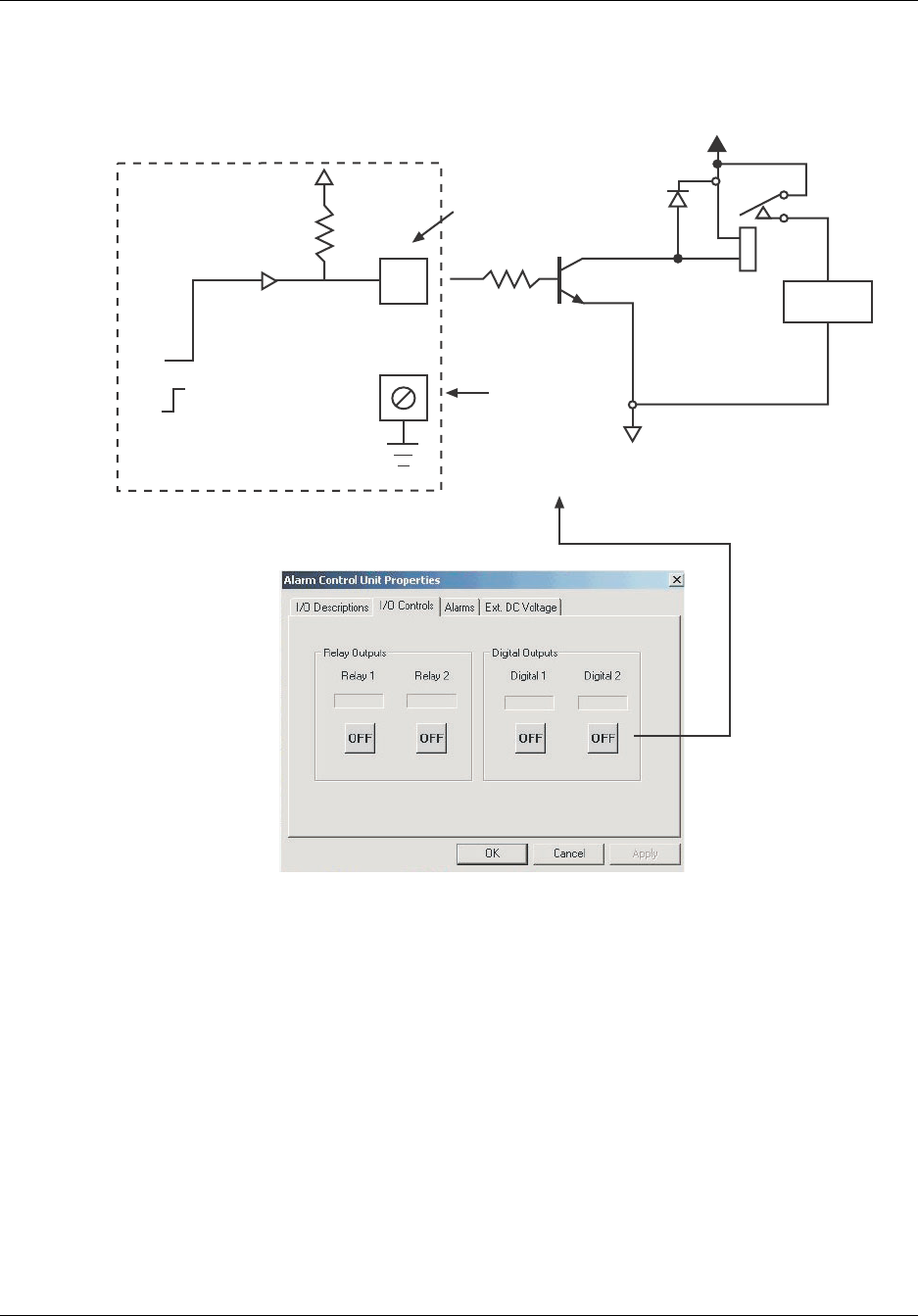
Reference Manual Connecting External Alarms and Relays
550-1300-01 Rev C RTI Confidential 6-7
Figure 6-5 Switching an Intrusion Alarm On and Off, Using Digital Output Number 2
RT213101
5V
0V
Chassis Ground
Terminal
+
-
VCC
Intrusion
Alarm
Repeater
1N4001
2N2222
4.7 k Ohm
Connector In/Out
(Pin 2)
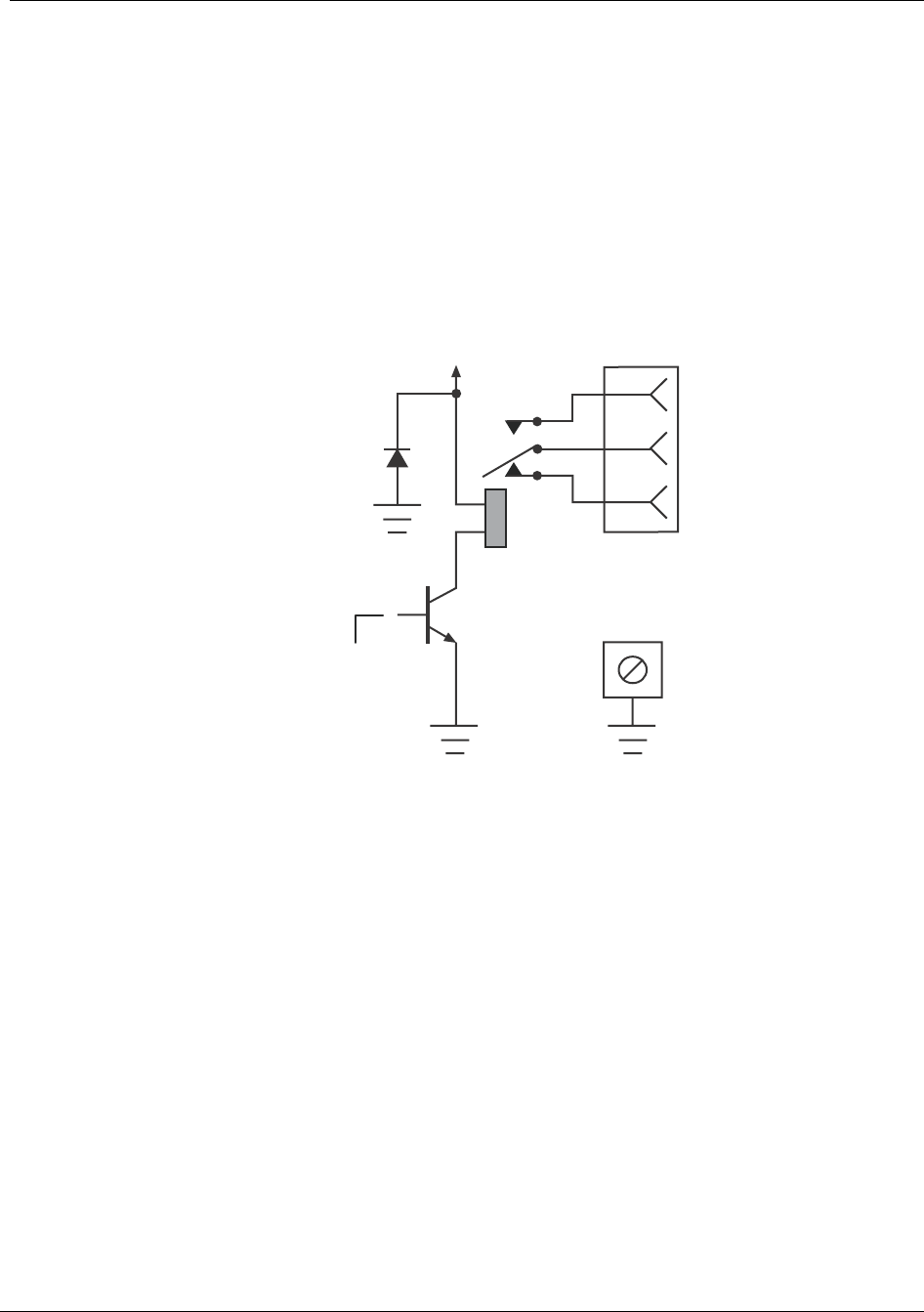
Connecting External Alarms and Relays Reference Manual
6-8 RTI Confidential 550-1300-01 Rev C
6.3 User Controlled Relays
The repeater provides two user-controlled relay outputs with form C contacts (SPDT).
These relays respond to user commands through the RepeaterNet or Craft software, sim-
ilar to those described above for digital outputs. When the RepeaterNet software sets one
of these relay switches to On, the transistor saturates, and energizes the relay. Figure 6-6
shows the relay in the energized or On state.
Figure 6-6 Typical Relay Output
The maximum switching characteristics for each of the user-controlled relays are:
Figure 6-7 shows a circuit that uses user-controlled relay output number 2 to control a
lamp at the repeater site.
Figure 6-8 shows a circuit that uses user-controlled relay output number 1 to control a fan
or blower at the repeater site.
Maximum current 30 VDC @ 2 Amperes or 125 VAC @ 0.5 Amps rms
Maximum switching voltage 220 VDC
+V
Repeater
+5V
0Chassis
Ground
Terminal
NO
NC
User Relay
RT213102
COM
Pin 2 or 5
Pin 1 or 4
Pin 3 or 6
Connector
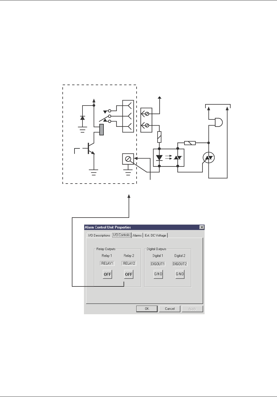
Reference Manual Connecting External Alarms and Relays
550-1300-01 Rev C RTI Confidential 6-9
Figure 6-7 Controlling a Lamp, Using Relay Output Number 2
+5V
0
4
6
5110 - 220 VAC 47 - 63 Hz
+24V
6
4100 Watt
Lamp
180 Ohm
G
MT2
61
2.2k
24 MT1
Chassis Ground Terminal
RT213103
+V
User Relay 2
Connecting External Alarms and Relays Reference Manual
6-10 RTI Confidential 550-1300-01 Rev C
Figure 6-8 Controlling a Fan or Blower, Using Relay Output Number 1
110 - 220 VAC 47 - 63 Hz
Chassis Ground Terminal
RT213104
+5V
0
1
3
2
3
1
+V
FAN
OR
BLOWER
(50W max)
User Relay 1
Reference Manual Connecting External Alarms and Relays
550-1300-01 Rev C RTI Confidential 6-11
6.4 Alarm Controlled Relays
You can use the alarm control relay contacts to activate external alarms or other equip-
ment in the event of a repeater alarm.
Whenever the repeater generates an alarm, it also generates a summary alarm for that
severity. For example, if the repeater generates a critical alarm, it also generates a critical
summary alarm. The repeater generates similar summary alarms for major and minor
alarms.
Each summary alarm is connected to a relay. Figure 6-9 shows the basic internal circuit.
When the repeater generates an alarm, the transistor saturates and energizes the relay as
shown in Figure 6-9.
Figure 6-9 Alarm Summary Relay Output - Typical
Figure 6-10 shows the critical alarm summary output relay, which is controlling an exter-
nal, dual-color (green/red) LED. Normally, the relay is open, and the green LED is biased
on. When an alarm occurs, the relay closes, and the LED turns red.
+V
Repeater
+5V
0
NO
COM
NC
RT213105
2, 5, or 8
3, 6, or 9
1, 4, or 7
Connecting External Alarms and Relays Reference Manual
6-12 RTI Confidential 550-1300-01 Rev C
Figure 6-10 Critical Alarm Summary Relay, Controlling an External LED
Figure 6-11 shows circuitry that connects all alarm summary relays to external lamps,
through a flasher. This circuit provides an external indication of any internal alarm in the
repeater.
+V
Repeater
+5V
0
1
3
2
RT213106
Critical Alarm
Summary Output 2
3
1
Chassis Ground Terminal
Red Green
+V
Alarm Relay Connector
Reference Manual Connecting External Alarms and Relays
550-1300-01 Rev C RTI Confidential 6-13
Figure 6-11 External, Flashing Alarm Lamps
+V
Repeater
+5V
0
4
6
5
RT213107
Major Alarm
Summary
output
+V
Repeater
+5V
0
7
9
8
Minor Alarm
Summary
Output
+V
Repeater
+5V
0
1
3
2
Critical Alarm
Summary
Output
2N2222
1k
2N2222
1k
2N2222
1k
4
6
5
1
3
2
+24 VDC
7
9
8
GREEN
OK
REG
5V
100mf
10V
1mf
21
470k
510k
48
7
2N4097
3
56
CRITICAL
RED
MAJOR
YELLOW
MINOR
BLUE
0.047mf
0.4 sec.
+5V
0V
0.6 sec.
All lamps: No. 327
28 VDC, 0.04 amps
555
Customer Supplied
Alarm
Relay
Alarm
Relay
Alarm
Relay

Connecting External Alarms and Relays Reference Manual
6-14 RTI Confidential 550-1300-01 Rev C

550-1300-01 Rev C RTI Confidential 7-1
7
Final Testing and Optimization
7.0 Link Engineering Considerations
7.0.1 Ensuring Adequate Isolation for a Repeater Application
Compare the maximum forward and reverse gain settings, to the available isolation.
• If the available isolation is at least 15 dB higher than the maximum gain setting, then
the repeater will operate with good stability.
• If the isolation is less than 15 dB higher than the maximum gain setting, then some
oscillation might result.
For CDMA systems, pre-oscillation begins at about 15 dB margin over gain, and becomes
very problematic at about 10 dB margin-over-gain. Therefore, you should strictly follow
the 15 dB margin-over-gain rule.
7.1 System Timing Issues
7.1.1 Worst-case Position for Active Search Window Width
This process estimates the required width setting for the active search window, to ensure
that the repeater properly covers a transition zone (between the base station and the
repeater).
The typical value required for SRCH_WIN_A=8. This value is more than sufficient for
most applications, where the repeater is less than three miles from the donor site, and the
repeater radius is two miles or less.
For additional information regarding system timing issues, call RTI.

Final Testing and Optimization Reference Manual
7-2 RTI Confidential 550-1300-01 Rev C
7.1.2 Worst-case Position for Neighbor Search Window Width
This process estimates the required width setting for the neighbor search window, to
ensure that the repeater properly covers a soft hand-off zone (between the base station
and the repeater).
The worst-case position is wherever the greatest differential delay exists, between the cell
that the mobile uses for timing and a hand-off candidate cell.
NOTE: This relationship is symmetrical and reciprocal for neighboring cells, if those
cells are candidates for the donor sector. That is, the neighbor cells also need wider search
windows.
Wider search windows can search the TOA (Time Of Arrival) of the specific pilot that is
associated with the donor sector (the pilot is accessible via the repeater).
The following equation calculates the differential delay:
Where:
The typical process is:
1. Determine the place where the differential delay is greatest and where a mobile is
likely to be operating.
2. Calculate the differential delay.
This worst-case differential delay determines the SRCH_WIN_N parameter setting.
The typical value required for SRCH_WIN_N (for repeater operation in the transition
zone) is about ± 40 chips. This corresponds to SRCH_WIN_N = 9. This value is more than
sufficient for most applications where the repeater is less than three miles from the donor
site and the repeater radius is two miles or less.
∆(Chips) = D+R+S-N(Chips)
∆(Chips) = Differential_Delay(Chips)
D = Donor_Path_Length(Chips)
R = Repeater_Delay(Chips)
S = Subscriber_Path_Length(Chips)
N = Neighbor_Path_Length(Chips)

Reference Manual Final Testing and Optimization
550-1300-01 Rev C RTI Confidential 7-3
7.1.3 Channel Search Window Width for Reverse Link Access
The mobile station searches the forward link TOA probability space for new pilot offsets.
A similar search process occurs at the base station.
The base station modem chip (CSM) also contains a searcher. Both the access channel and
the traffic channel use this searcher to determine the TOA of the mobile's energy. Because
the access channel does not know how far an originating mobile is from the base station,
it must search the entire TOA probability space associated with the cell's maximum
radius.
For example, if the cell has a maximum radius of 20 chips, then the searcher must search
the range of relative TOA, from near zero chip delay (for very close mobiles), to delays as
great as 40 chips.
NOTE: The round trip delay is the important variable, because the mobile is "phase
locked" to the PN sequence of the down-link (forward link) path. Also, the TOA (round-
trip delay) of the base station is twice the one-way delay.
The cell radius plays a central role in determining the required width for the access-chan-
nel search window. Most CDMA network manufacturers derive all of the required search
window parameters from a simple parameter, called Cell_Radius or something similar.
Usually, if you set this parameter to the maximum cell radius, the Method Of Repeater
Engineering (M.O.R.E.) automatically calculates and updates all corresponding parame-
ters (such as preamble size, PROBE_RAN_N, and so on).
NOTE: You must set this parameter properly. An incorrect setting can limit the range of
access to the base station via the repeater.
The setting for this parameter is simply the sum of the donor link radius, the repeater
delay in miles, and the maximum repeater coverage range as shown in the following
equation:
Cell_Radius(miles) =
Donor_Path_Length(miles)+[Repeater_Delay(
µ
s)]*0.186+Repeater_Radius(miles)
If the equipment manufacturer does not provide a Cell Radius type parameter, or if you
need more information on this subject, please contact the Repeater Technologies Applica-
tion Engineering Group.

Final Testing and Optimization Reference Manual
7-4 RTI Confidential 550-1300-01 Rev C
7.1.4 Setting Radius of Traffic Channel Search Window
The new base station must acquire the reverse traffic channel during a soft hand-off
attempt. The search process is similar to the one that the access channel performs during
initial system access.
The Primary Base Station (initial base station) receives the Pilot PN Phase information in
the Pilot Strength Measurement Message. You can use this information to estimate the
Time of Arrival (TOA) at the new base station. This can significantly reduce the acquisi-
tion time of the reverse traffic channel. Due to the dynamic nature of the mobile propaga-
tion environment, and the delay associated with hand-off processing, the search window
must be wider than a single-point Time of Arrival (TOA) set. Typically, the reverse traffic
channel search window centers around the estimated TOA, and its width depends on
two factors:
•The accuracy of the TOA estimate.
•The maximum expected variation of the TOA during hand-off processing.
If the CDMA equipment manufacturer uses the Pilot PN Phase to estimate the TOA at the
neighbor base station, then the search window width needs to be only a few tens-of-chips
wide (± 20 chips). This is typically the case; however, some manufacturers might not use
the Pilot PN Phase data to estimate the TOA.
If the TOA estimate is not available for the neighboring base station, then you must run a
complete search of all possible Times of Arrival, just as you do during the access channel
search process. In this case, the search process takes longer, and therefore the hand-off is
slower. The required width of he search window, used in this process, depends on the
TOA of the mobile's energy at the new base station.

Reference Manual Final Testing and Optimization
550-1300-01 Rev C RTI Confidential 7-5
The equation that calculates the TOA is similar (but not identical to) setting the neighbor
search window:
Where:
After calculating the worst-case TOA, you can set the search window width accordingly.
7.1.5 Updating an MTSO Data Base Using New Timing Parameters
After you determine all of the parameters, you can update both the Mobile Telephone
Switching Office (MTSO) data base, and the repeater data base, using the proper parame-
ters. Do not perform this update until you are ready to activate the repeater.
TOA
(Chips)
= D+R+S+N(Chips)
TOA(Chips) = Differential_Delay(Chips)
D = Donor_Path_Length(Chips)
R = Repeater_Delay(Chips)
S = Subscriber_Path_Length(Chips)
N = Neighbor_Path_Length(Chips)

Final Testing and Optimization Reference Manual
7-6 RTI Confidential 550-1300-01 Rev C
7.2 Drive Testing Requirements
7.2.1 Collecting Data
To ensure proper repeater operation, drive test all of the following areas:
•Repeater Coverage area
•Transition zone between the donor base station coverage area and the repeater
coverage area
•Soft hand-off zones between the repeater and adjacent cell sites
For CDMA networks, RTI recommends that you accumulate data for both the forward
and reverse link, at the same time. Usually, this requires invoking "call trace," or some
similar function within the switch. Once invoked, the switch logs the test call by time
stamp. You can later correlate this to the forward link data.
This method helps you to more-accurately analyze the link balance and identify areas of
high RFER and/or high Mobile_TX parameters.
7.2.2 Collection Equipment
•The minimum equipment required for drive testing is:
•CDMA phone
•Serial data cable
•Laptop or notebook computer, running collection software
•GPS receiver
This equipment is available from a variety of sources, such as:
•Qualcomm, Incorporated
•Agilent
•Grayson
•LCC, Inc.
•Berkeley Veritronics
Analyzing the drive test results might require a change in network timing parameters,
and/or adjustment of the repeater subscriber antenna. That is, you must optimize
repeater, using the same methods as you use for a base station.

550-1300-01 Rev C RTI Confidential 8-1
8
CDMA Overview
8.0 Introduction
In a CDMA (IS95) network, the dynamic RF power output of a Base Transceiver Station
(BTS) depends on the number of subscribers assigned to the BTS.
The IS-95 specification, for CDMA networks, describes four different channel types, all
contained within the forward channel:
•One pilot channel (measures power and performs initial synchronization)
•One sync channel (passes parameters during initial synchronization)
•0 to 6 paging channels (passes parameters during operation)
•0 to 62 traffic channels
The total number of channels cannot exceed 64.
Usually, a portion of the base station’s total power is assigned to the pilot channel, the
paging channel, and the sync channel. The traffic channels use the remaining power. For
example, within an IS-95 network, the power allocations usually adhere to the following
convention:
The remaining 72-77% of the BTS power is available for communications traffic channels.
For each repeater installed into a CDMA network, you must determine the received
power level from the donor BTS, so that you can accurately set the repeater gain. If you
do not know the received power level, or if you use an inaccurate value, then the repeater
might become over driven, and it might enter into an alarm condition.
Pilot Channel Power: 15 – 20%, depending on the requirements of the specific
equipment manufacturer or service provider
Paging Channel Power: 6%
Sync Channel Power: 2%
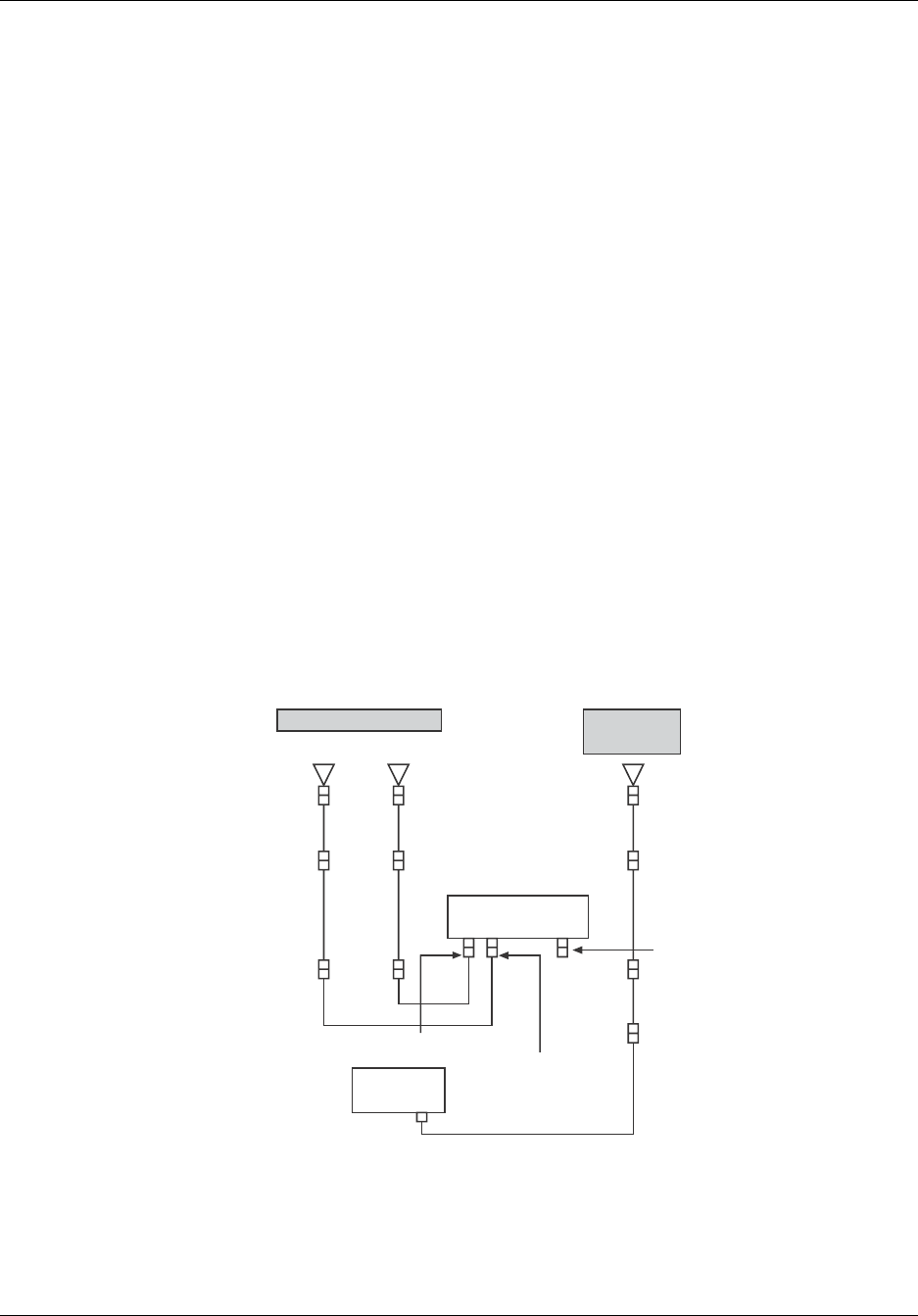
CDMA Overview Reference Manual
8-2 RTI Confidential 550-1300-01 Rev C
8.1 Measuring the Donor BTS Signal Strength
If the donor BTS is idle (not carrying any subscriber traffic), you can assume that the
repeater is radiating only pilot, paging, and sync power. If this is the case, connect a spec-
trum analyzer to the bottom jumper cable of the repeater’s donor antenna, and measure
the BTS power. Either use a spectrum analyzer that is equipped with a CDMA module, or
correct for the resolution bandwidth of the spectrum analyzer.
For example, a CDMA Personality Module is available for Agilent spectrum analyzers to
measure CDMA power within a 1.25 MHz band. For spectrum analyzers that do not have
such a module, however, the closest measurement bandwidth is 1.0 MHz, and you must
correct the measurement for bandwidth.
8.1.1 Measuring Donor BTS Idle Power
If the donor BTS is idle (no subscribers), then the only power that the BTS transmits is
pilot, paging, and sync. If this is the case, you can use either of two measurement meth-
ods:
•Spectrum analyzer
•Pilot Scanner (CDMA)
Both methods use the same equipment configuration, as shown in Figure 8-1.
Figure 8-1 Equipment Configuration for Measuring Donor BTS Power
Subscriber Antennas Donor
Antenna
Diversity Main
REPEATER
Spectrum
Analyzer
Main Subscriber Port
Diversity
Subscriber
Port
Donor
antenna
port
RT130104

Reference Manual CDMA Overview
550-1300-01 Rev C RTI Confidential 8-3
Measurement Using a Spectrum Analyzer
Use the following procedure with a spectrum analyzer, to measure power from the Donor
BTS to the repeater.
1. Connect the spectrum analyzer to the output end of the bottom jumper cable on the
repeater donor antenna, as shown in Figure 8-1.
2. Ensure that the donor BTS is idle (no subscribers), and that only the pilot, paging and
sync channels are active.
NOTE: If the spectrum analyzer does not have a CDMA measurement module, skip to
step 4.
3. If the spectrum analyzer has a CDMA measurement module or capability, configure
the analyzer to measure the CDMA signal. Then record the signal strength, and skip
to step 5.
4. If the spectrum analyzer does not have a CDMA measurement module, proceed as
follows:
a. Configure the spectrum analyzer for a resolution bandwidth of 1.0 MHz, and for a
video resolution of 30 kHz.
b. Set Video averaging to ON.
c. Note and record the signal strength.
d. To correct the reading for a 1.25 MHz bandwidth, add 0.9 dB to the reading. For
example, if the spectrum analyzer indicates –55 dBm, the corrected reading is
-54.1 dBm (-54 dBm, for all practical purposes).
5. Move the antenna for maximum signal strength.
8.1.2 Measuring donor BTS Loaded Power
If the donor BTS is active (carrying subscriber traffic), you cannot use a spectrum ana-
lyzer to obtain an accurate measurement of the donor BTS signal strength. In this case,
you must use a Pilot Scanner and measure Pilot power directly.
Measurement Using a Pilot Scanner
1. Configure equipment as shown in Figure 5-1, but substitute a pilot scanner for the
spectrum analyzer.
2. Configure the pilot scanner to measure ONLY the pilot channel of the donor BTS.
3. Move the antenna for maximum signal strength.

CDMA Overview Reference Manual
8-4 RTI Confidential 550-1300-01 Rev C

550-1300-01 Rev C RTI Confidential 9-1
9
Technical Specifications
9.0 Specifications
Table 9-1 PCS Frequencies
Table 9-2 RF Characteristics
Block Bandwidth Reverse Link
(Mobile Tx)
Forward Link
(Base Tx)
A 15 MHz 1850-1865 1930-1945
B 15 MHz 1870-1885 1950-1965
C 7.5/15 MHz 1895-1910 1975-1990
D 5 MHz 1865-1870 1945-1950
E 5 MHz 1885-1890 1965-1970
F 5 MHz 1890-1895 1970-1975
Link RF Output Power at the Antenna Port Gain Frequency
Range
Channel 1 Channel 2
Forward RC19-1X10 +40.0 dBm
RC19-1X15 +41.8 dBm
RC19-2X10 +40.0 dBm
RC19-2X15 +41.8 dBm
RC19-2X10 +40.0 dBm
RC19-2X15 +41.8 dBm
65-95 dB Block Specific
Main +18 dBm +18 dBm 65-95 dB Block Specific
Diversity +18 dBm +18 dBm 65-95 dB Block Specific

Technical Specifications Reference Manual
9-2 RTI Confidential 550-1300-01 Rev C
Table 9-3 Mechanical Characteristics
Table 9-4 Noise Figure
Table 9-5 Additional Characteristics
Table 9-6 Alternate Power Options
Table 9-7 RepeaterNet Alarm, Monitoring, and Control
Size Weight Temperature
RC19-1X10 16"(W) x 21(H)" x 16"(D)
RC19-1X15 20"(W) x 30(H)" x 16"(D)
RC19-2X10 16"(W) x 21(H)" x 16"(D)
RC19-2X15 20"(W) x 30(H)" x 16"(D)
RC19-1X10 70 lbs.
RC19-1X15 107 lbs.
RC19-2X10 74 lbs.
RC19-2X15 111 lbs.
-40° to 55° C Ambient
Reverse Link (Independent Main &
Diversity Paths)
Reverse Link (Combined Main & Diver-
sity Paths)
3.2 dB typical
6.7 dB typical (Dual Direction option)
7.0 dB typical
10.5 dB typical (Dual Direction Option
Waveform
Quality Factor (ρ)
Spurious
Response
Channel
Bandwidth
Group Delay Maximum
Input Signal
VSWR
>0.96 Per TIA-95D &
IS-2000
<1.25 MHz <2 µsec forward &
reverse main links
+10 dBm <1.8:1
<4 µsec diversity
link
Type Descrip tion
BUPS 5 - 9 hours of backup power without AC
Solar Power Photovoltaic (PV) with regulated charging batteries
Hybrid Solar and TEG PV with thermal electric propane generation assistance
Hybrid Solar and MG PV with propane or diesel generation assistance
Access Options GUI Functions
• RS-232 (local)
• POTS (dial-up)
• Wireless Modem (CDMA)
• Craft - Win95/98/NT/2000/ME
•NMS - WinNT
•Fault Notification
• Interrupt Reporting
• Definable Threshold
• Remote Control: Gain,
Channel, PA On/Off

Reference Manual Technical Specifications
550-1300-01 Rev C RTI Confidential 9-3
Table 9-8 Inputs and Outputs
Table 9-9 LED Indicators
Table 9-10 Electrical Characteristics
Local I/O Type
Critical Alarm Form C Relay
Major Alarm Form C Relay
Minor Alarm Form C Relay
Remote Control Relay (2) Form C Relay
Digital Input (4) Open Collector TTL
Digital Output (4) Open Collector TTL
External Voltage Monitor Analog
BUPS Monitor 6 Alarms
LED Color
System Ready Green
Critical Alarm Red
Major Alarm Red
Minor Alarm Red
Voltage Current (Typical) Lightning Protection Connectors
100 to 264 VAC RC19-1X10 2.2 Amps @ 115 VAC
RC19-1X15 2.9 Amps @ 115 VAC
RC19-2X10 3.5 Amps @ 115 VAC
RC19-2X15 4.1 Amps @ 115 VAC
• Internal - All inter-
face cables
• RF - Type N (f)
22 to 32 VDC RC19-1X10 9.0 Amps @ 24 VDC
RC19-1X15 11.0 Amps @ 24 VDC
RC19-2X10 13.0 Amps @ 24 VDC
RC19-2X15 15.0 Amps @ 24 VDC
•External - Optional

Technical Specifications Reference Manual
9-4 RTI Confidential 550-1300-01 Rev C
9.1 Ordering Information
The tables that follow provide information about ordering from RTI; specifically:
•Ordering Considerations
•Repeater Configurations and Part Numbers
•Optional Equipment Available from Repeater Technologies
•Back-up Power Systems (BUPS)
•Accessory Kit Items
When ordering, specify a shipping destination and a billing address. Repeater Technolo-
gies will return an order acknowledgment and the scheduled shipping date. Each ship-
ment includes an equipment list, showing the equipment ordered, and the equipment
shipped. This list includes details about system equipment options. Contact the Repeater
Technologies Sales Department for ordering information.
Table 9-11 Spare Parts and Accessory Items
Description Part Number
Antennas* Call for information
Connectors Call for information
Coaxial Cable Call for information
AC Power Cord 103-0137-01
Pole Mounting Kit 091-0215-01
McMaster-Carr ¾-inch Banding Kit Part No. 5653K12, McMaster-Carr Supply Co.,
Los Angeles, CA, USA, Tel.# (562) 692-5911
Internal Lead Acid Back-Up Battery 149-1028-01
PC Interface Cable DB9, 9-pin, and Serial
Straight Through Male-to-Female
187-0713-02
BUPS-25/80 (AC Power System) for RC19-1X10
or RC19-2X10
250-1011-07
BUPS-25/80 (AC Power System) for RC19-1X15
or RC19-2X15
TBD
Surge Protector - N(M) to N(F) Lightning Call RTI
Operations Manual (Hard Copy) 550-1300-01
Alarm, Power, and Button Plugs (7/8”) 126-0062-01
Conduit Fitting 137-0447-01
Back Mounting Plate 020-1339-02
Stainless Steel 3/8” Locking Washer 125-0059-07
Stainless Steel 3/8” x 1" Flat Washer 125-0068-07

Reference Manual Technical Specifications
550-1300-01 Rev C RTI Confidential 9-5
To select a BUPS (Back-up Power System) for the repeater application, match the repeater
with the amount of back-up time required. See appropriate BUPS manual.
Table 9-12 Contents of Accessory Kit
Stainless Steel Pin-in-Head Security Bolts 125-0212-13
Stainless Steel Hex Head Bit Pin-in-Head, 7/32” 129-0008-01
RepeaterNet Craft Software 519-1200-03
BUPS Power & Alarm Cable Assy (Kit) 187-0188-01
*Typical antennas include parabolic reflectors, corner reflectors, circular, linear, directional co-linears, cross or
slant polarization, log periodic array, or Yagi.
Quantity Item
1 each PC Interface Cable DB9, Serial Straight Through Male-to-Female
1 each Hex bit, Pin-in-Socket, 7/32”
1 each Operations Manual (Hard Copy)
1 each RepeaterNet Craft Software
Table 9-11 Spare Parts and Accessory Items (Continued)
Description Part Number

Technical Specifications Reference Manual
9-6 RTI Confidential 550-1300-01 Rev C
9.2 Technical Services
Repeater Technologies offers technical services to supplement the manpower resources of
its customers. RTI will provides quotations for the following services upon request:
•Site and Construction surveys
•Network Design
•Design Verification
•Training
•Installation
•Accessories (antenna, coaxial cabling, etc.)
•Alignment and Optimization
9.3 Customer Support
Repeater Technologies, Inc.
Corporate Headquarters (8 a.m. to 5 p.m. Pacific Standard Time, Monday-Friday)
1150 Morse Avenue
Sunnyvale, CA 94089 USA
Customer Service (7 days a week, 24 hours per day)
(408) 747-1946
(800) 747-1515 (USA and Canada only)
www.repeaters.com

550-1300-01 Rev C RTI Confidential A-1
A
Default Settings
Table A-1 Default Settings
Subsystem Option Setting Default
Front End Fwd FE FwdFE Summary Alarm Major
Rev FE RevFE Offline Alarm
RevFE Current Alarm
RevFE HotTone Alarm
Major
Major
Minor
Diversity FE Control Diversity FE Control On
Diversity FE Attn Attenuation 6 dB

Default Settings Reference Manual
A-2 RTI Confidential 550-1300-01 Rev C
Channel 1 Rev PA RevPA1 Offline Alarm
RevPA1 Current Alarm
RevPA1 ALC Alarm
Major
Major
Minor
Fwd PA FwdPA1 Offline Alarm
FwdPA1 Temp Alarm
FwdPA1 Thermal Shutdown Alarm
FwdPA1 Overdrive Shutdown Alarm
FwdPA1 Low RF Power Alarm
FwdPA1 ALC Alarm
FwdPA1 Return Loss Alarm
FwdPA1 Off Alarm
Major
Major
Critical
Critical
Event
Minor
Major
Critical
PA Control Reverse PA Power
Forward PA Power
Off
Off
Rev Filter RevCSF1 Offline Alarm
RevCSF1 Current Alarm
RevCSF1 Lock Alarm
Major
Major
Critical
Fwd Filter FwdCSF1 Offline Alarm
FwdCSF1 Current Alarm
FwdCSF1 Lock Alarm
Major
Major
Critical
Channel # Channel Number Block Specific
Gain Forward Gain
Forward ALC
Forward ALC Duration
Reverse Gain
Reverse ALC
Reverse ALC Duration
65 dB
On
10 sec.
65 dB
On
10 sec.
Table A-1 Default Settings (Continued)
Subsystem Option Setting Default

Reference Manual Default Settings
550-1300-01 Rev C RTI Confidential A-3
Channel 2* Rev PA RevPA2 Offline Alarm
RevPA2 Current Alarm
RevPA2 ALC Alarm
Major
Major
Minor
Fwd PA FwdPA2 Offline Alarm
FwdPA2 Temp Alarm
FwdPA2 Thermal Shutdown Alarm
FwdPA2 Overdrive Shutdown Alarm
FwdPA2 Low RF Power Alarm
FwdPA2 ALC Alarm
FwdPA2 Return Loss Alarm
FwdPA2 Off Alarm
Major
Major
Critical
Critical
Event
Minor
Major
Critical
PA Control Reverse PA Power
Forward PA Power
Off
Off
Rev Filter RevCSF2 Offline Alarm
RevCSF2 Current Alarm
RevCSF2 Lock Alarm
Major
Major
Critical
Fwd Filter FwdCSF2 Offline Alarm
FwdCSF2 Current Alarm
FwdCSF2 Lock Alarm
Major
Major
Critical
Channel # Channel Number Block Specific
Gain Forward Gain
Forward ALC
Forward ALC Duration
Reverse Gain
Reverse ALC
Reverse ALC Duration
65 dB
On
10 sec.
65 dB
On
10 sec.
Table A-1 Default Settings (Continued)
Subsystem Option Setting Default
*Two channel repeaters only

Default Settings Reference Manual
A-4 RTI Confidential 550-1300-01 Rev C
Alarm Control
Unit
I/O Controls Relay 1
Relay 2
Digital 1
Digital 2
Off
Off
Off
Off
Alarms Line Entry Offline Alarm
ACU Offline Alarm
Ext Input 1 Alarm
Ext Input 2 Alarm
Ext Input 3 Alarm
Ext Input 4 Alarm
Ext DC Voltage Alarm
Ext Tamper Alarm
Primary Tamper Alarm
All RF Off Alarm
Major
Major
Disabled
Disabled
Disabled
Disabled
Disabled
Disabled
Major
Critical
Ext DC Voltage Less Than Threshold
Greater Than Threshold
0 V
60 V
Remote
Monitoring
Alarm Setting Modem System Alarm
CellPhone System Alarm
NMS DialOut Alarm
Disabled
Disabled
Disabled
Power System Alarm Setting Power Control Offline Alarm
System Voltage Alarm
Small Backup Battery Alarm
AC Power Supply Fail Alarm
AC Input Fail Alarm
Primary Battery Charger Alarm
Major
Critical
Major
Disabled
Disabled
Event
Battery Control Enable Battery Controlled Shutdown
Battery Charger Enable
On
Off
BUPS Alarm Setting Ext BUPS AC (Mains) Fail Alarm
Ext BUPS Low (Float) Battery Alarm
Ext BUPS High (Float) Battery Alarm
Ext BUPS Charger (Rectifier) Fail Alarm
Ext BUPS Summary (Load/Bat Fuse) Alarm
Ext BUPS Tamper (Optional) Alarm
Disabled
Disabled
Disabled
Disabled
Disabled
Disabled
Table A-1 Default Settings (Continued)
Subsystem Option Setting Default

550-1300-01 Rev C RTI Confidential B-1
B
Glossary
This glossary defines communications industry acronyms, symbols, and terms. Hard-
ware-related and software-related acronyms are also included. Because this glossary sup-
plements all operations manuals from Repeater Technologies, not all items listed here
necessarily appear in this manual.
AAmp or Amps.
ACU Alarm Control Unit.
ALC Automatic Level Control.
AMPS Advanced Mobile Phone System.
API Application Programming Interface.
Back-beam A back-beam antenna transmits energy backward, towards the donor BTS. This increases the
allowable distance between the donor BTS and repeater sites in CDMA networks.
BNC Bayonet Naval Connector. Type of connector.
BTS Base Transceiver Station.
BUPS Back-Up Power Supply.
CDMA Code Division Multiple Access.
C/E Carrier-to-Echo Ratio.
C/I Carrier-to-Interface Ratio. The ratio between the mean signal level of the desired radio signal,
and the signals from other (interfering) sources. Typically expressed in dB.
CPC Circular Plastic Connector.
CRC Cyclical Redundancy Check.
CSM Cell Site Modem.
DAMPS Digital Advanced Mobile Phone System (equivalent of TDMA).

Glossary Reference Manual
B-2 RTI Confidential 550-1300-01 Rev C
Darlington Pair Two transistors, arranged so that the emitter of one drives the base of the other, and connects
the collectors together. The result is an increase in gain compared to a single transistor,
because the gains of the two transistors are multiplied together. The trade-off for this
increased gain is reduced speed, because of the very high gain's effect on the collector-to-base
capacitance. You can use this pair of transistors as a single transistor: common emitter, emit-
ter follower, and so on.
dB Decibel or decibels.
dBC Decibels, referenced to the carrier level.
dBi Decibels, referenced to an isotropic antenna.
dBm Decibels, referenced to one milliwatt.
DF, DFB Distributed Feedback (Laser).
Donor An antenna that communicates between a repeater and a BTS.
DSN Data Source Name. A name that represents the database file (or connection).
DVM Digital Voltmeter.
EM Electromagnetic.
EMI Electromagnetic Interference.
ERP Effective Radiated Power.
F/B Front-to-Back Ratio.
FCC Federal Communications Commission (USA).
FE Front End.
FIFO First In First Out.
Forward Direction Direction of transmission from the base station, through the repeater, and on to Mobile or
hand-held units. Downlink transmission.
Forward Gain Gain setting for Forward (downlink) transmissions.
FRU Field Replaceable Unit
FSK Frequency-Shift Keying.
Gain The amount of signal amplification between the repeater input and output.
GSM Global System for Mobile Communications, or Groupe Speciale Mobile.
GUI Graphical User Interface.
Hand-off On a cellular system, the act of transferring a call in progress, from one cell or sector to
another. Typically also involves changing to a different voice channel.
HBW Horizontal Beam Width of an antenna.
Hot Tone A large RF signal at the input of the repeater which is not under control of the BTS.
HPP Half Power Point of an antenna.
IF Intermediate Frequency.

Reference Manual Glossary
550-1300-01 Rev C RTI Confidential B-3
IM Intermodulation.
IMD Intermodulation Distortion.
LED Light-Emitting Diode.
LNA Low Noise Amplifier.
LO Local Oscillator.
LOS Line-Of-Sight.
Microcell Any small, low-power cell site.
M.O.R.E. Method Of Repeater Engineering. Controls signal noise and gain between the base trans-
ceiver station (BTS) and the repeater.
Morphology The structure (layout) of the repeater coverage area. Morphology factors include natural sig-
nal-path obstructions (trees and hills), man-made obstacles (buildings and billboards), dis-
tance between the repeater and the base station, number of cell-phone users within the
repeater coverage area, and coverage inside buildings and tunnels.
MPRL Maximum Power Radiation Limit of an antenna.
MSC Mobile Switching Center (equivalent to MTSO).
MTSO Mobile Telephone Switching Office (equivalent to MSC).
Multipath Radio propagation between a transmitter and receiver, where the received signal contains
multiple rays. Each ray has undergone one or more reflections and/or refractions. Cellular
coverage is usually multipath, especially in high-density city areas.
NIM Noise Injection Margin. The amount of noise (dB) that a repeater injects into the CDMA air
interface.
NR Network Repeater.
ODBC Open DataBase Connectivity. An Application Programming Interface (API) in Windows, that
lets a programmer abstract a program from a database.
OLE Object Linking and Embedding. Integrates applications, and permits copying objects from
one application to another. Uses the first application’s editing techniques, when editing a
copied object in the second application.
OTU Optical Transceiver Unit.
PA Power Amplifier.
Paging Channel Passes parameters over a CDMA network, during operation.
PEP Peak Envelope Power.
Pilot Channel Measures power and performs initial synchronization over a CDMA network.
PLL Phase Locked Loop.
PSTN Public Switched Telephone Network.
QCCB Quick-Connect Connecting Block.
RBS Radio Base Station. See also BTS.

Glossary Reference Manual
B-4 RTI Confidential 550-1300-01 Rev C
Reverse Direction Direction of transmission from the Mobile or portable, through the repeater, and on to the
BTS. Uplink transmission.
Reverse Gain Gain setting for Reverse (uplink) transmissions.
RF Radio Frequency.
RFI Radio Frequency Interference.
RMA Returned Materials Authorization. Issued before you return a repeater to RTI for upgrading.
ROT Rise Over Thermal. The amount of increase in noise level (dB) at the BTS, that the repeater
creates.
RPE Radiation Pattern Envelope. Defines the attenuation of side-lobe energy from an antenna.
RSL Receive Signal Level.
RSA Rural Service Area.
RSSI Receive Signal-Strength Indicator.
RTI Repeater Technologies, Inc.
RX Receive.
SID System ID. A five-digit number that the FCC assigns for system identification.
Simulcast The process of transmitting the same signal from two or more sites simultaneously.
SMA Sub Miniature A (a type of connector).
SMB Sub Miniature B (a type of connector).
Subscriber An antenna that communicates between a repeater, and either a cellular phone or another
repeater.
Sync Channel Passes parameters during initial synchronization of a CDMA network.
TDMA Time Division Multiple Access (equivalent to DAMPS).
Traffic Channel Carries communications traffic over a CDMA network.
TSA Traffic Service Area.
TX Tra nsmit.
UCU Universal Control Unit.
UHF Ultra High Frequency.
UPS Uninterruptable Power Supply. The BUPS is a type of UPS.
VVolt or Volt s.
VA C Voltage, Alternating Current.
VDC Voltage, Direct Current.

Reference Manual Glossary
550-1300-01 Rev C RTI Confidential B-5
Voco d er Avocoder, or voice coder, divides speech signals into various bands of the audio spectrum,
compresses and encrypts the resulting audio segments, and transmits the digitized speech
over a cellular (wireless) network. The cellular phone (receiver) decrypts, decompresses, and
reassembles the transmitted audio segments, to sound like normal (analog) speech again.
VSWR Voltage Standing Wave Ratio.
WWatt or Watts.
XPD Cross Polarization.

Glossary Reference Manual
B-6 RTI Confidential 550-1300-01 Rev C