Respironics 1017226 Sleep Diagnosis System User Manual
Respironics Inc. Sleep Diagnosis System
User Manual

The Alice® 5 system is covered by the following patent: U.S. Patent No. 6,425,861.
The information contained in this document is the property of Respironics, Inc. Except as
specifically authorized in writing by Respironics, the holder of this document (1) shall keep all
information contained herein confidential and shall protect same in whole or in part from disclo-
sure and dissemination to all third-parties, and (2) shall use same for operation and maintenance
purposes only.
All information contained in this document is subject to change without notice. Respironics
reserves the right to make changes to equipment design or program components, as progress in
engineering, manufacturing methods, or other circumstances may warrant.
Alice®, Respironics®, and the Respironics logo are registered trademarks of Respironics, Inc.
All other trademarks are owned by their respective companies.
© 2004 Respironics, Inc. All rights reserved.

Table of Contents
i
Table of Contents
Chapter 1: Introduction...............................................................................................................1-1
1.1 Alice 5 System Contents ...............................................................................................1-2
1.2 Warnings and Cautions ..................................................................................................1-4
1.2.1 Warnings ..............................................................................................................1-4
1.2.2 Cautions ..............................................................................................................1-5
1.3 Intended Use ..................................................................................................................1-6
1.4 Hardware Component Overview ...................................................................................1-7
1.4.1 Data Flow through the Alice 5 Components .......................................................1-7
1.4.2 Alice 5 Base Station ............................................................................................ 1-9
1.4.2.1 Base Station Rear Panel ..........................................................................1-11
1.4.3 Headbox ..............................................................................................................1-14
1.5 Symbol Key ...................................................................................................................1-16
1.5.1 Headbox Symbols ...............................................................................................1-16
1.5.2 Base Station Back Panel Symbols ......................................................................1-17
1.5.3 Base Station Control Panel Symbols ..................................................................1-18
1.6 Acronyms and Definitions .............................................................................................1-18
1.7 Contacting Customer Service ........................................................................................1-21
Chapter 2: Alice 5 Equipment Setup ..........................................................................................2-1
2.1 Before You Begin ..........................................................................................................2-2
2.2 Setting Up Your Network ..............................................................................................2-2
2.2.1 Network Setup Examples .................................................................................... 2-2
2.2.2 Using a Point-to-Point Setup ...............................................................................2-5
2.2.2.1 Map Your Facility’s Network Setup ........................................................2-6
2.2.3 Using a Wired Network Setup ............................................................................2-7
2.2.4 Using an Access Point Infrastructure Network ...................................................2-8
2.2.5 Connecting the Alice 5 Hardware Components ..................................................2-10
2.3 Integrating Alice 3 and Alice 4 Devices into your Alice 5 Network .............................2-16
2.4 Adding Accessories .......................................................................................................2-17
2.4.1 Installing Video Cameras and/or Video Servers .................................................2-17
Chapter 3: Software Installation and Setup ................................................................................3-1
3.1 Alice Sleepware Software Installation ..........................................................................3-2
3.2 Adding Alice Devices ....................................................................................................3-6
3.2.1 Adding an Alice 5 Device ...................................................................................3-6

ii
Alice
®
5 Setup and User’s Guide
Chapter 4: Running Data Acquisitions .......................................................................................4-1
4.1 Overview .......................................................................................................................4-1
4.2 Patient Setup ..................................................................................................................4-2
4.2.1 Attaching EEG Electrodes ..................................................................................4-3
4.2.2 Attaching ECG Electrodes ..................................................................................4-6
4.2.3 Attaching Chest and Abdomen Effort Sensors ....................................................4-8
4.2.4 Attaching the EOG and EMG Electrodes ...........................................................4-9
4.2.4.1 EOG Electrodes .......................................................................................4-9
4.2.4.2 Leg EMG Electrodes ...............................................................................4-9
4.2.4.3 Chin EMG Electrodes .............................................................................4-9
4.2.5 Attaching the Airflow Sensor ..............................................................................4-10
4.3 Starting an Acquisition ..................................................................................................4-11
4.3.1 Check Your Cable Connections .......................................................................... 4-11
4.3.2 Check Your Equipment Performance .................................................................. 4-12
4.3.2.1 Check Impedance Using the Alice Sleepware ........................................4-12
4.3.2.2 Check Calibration ................................................................................... 4-13
4.3.3 Starting an Acquisition ........................................................................................4-15
4.2.4 Stopping an Acquisition ......................................................................................4-16
Chapter 5: Understanding Channels ...........................................................................................5-1
5.1 Headbox Channels .........................................................................................................5-2
5.2 Base Station Auxiliary Channels ................................................................................... 5-10
5.2.1 Display Properties of Auxiliary Input Channels .................................................5-10
Graphic Display Type .........................................................................................5-11
Grapho-Numeric Display Type ...........................................................................5-11
Numeric Display Type ........................................................................................5-12
5.2.2 Base Station Auxiliary Channel Descriptions .....................................................5-12
5.3 Therapy Device Channels ............................................................................................. 5-14
5.4 Derived Channels ..........................................................................................................5-17
Chapter 6: Cleaning and Maintenance .......................................................................................6-1
6.1 Base Station, Headbox, and Patient Cable ....................................................................6-1
6.2 Sensors .......................................................................................................................... 6-2
6.2.1 EEG Electrodes ...................................................................................................6-2
6.2.2 ECG Sensors .......................................................................................................6-2
6.2.3 Airflow Sensors ...................................................................................................6-2
6.2.4 Snore, Actimeter, and Body Position Sensors .....................................................6-2
6.2.5 Effort Belts ..........................................................................................................6-2
Chapter 7: Troubleshooting ........................................................................................................7-1
Chapter 8: Specifications ............................................................................................................8-1
8.1 Device Size ....................................................................................................................8-1
8.2 Classifications and Ratings ........................................................................................... 8-2
8.3 Disposal .........................................................................................................................8-3
Appendix A: EMC Information ..................................................................................................A-1
Guidance and Manufacturer’s Declaration - Electromagnetic Emissions ................... A-1
Guidance and Manufacturer’s Declaration - Electromagnetic Immunity ....................A-2

1–1
Introduction
CHAPTER
1
Introduction
The Alice® 5 Setup and User’s Guide contains instructions on how to set up your Alice 5 equip-
ment so you can successfully run your sleep studies. It provides detailed information on:
•Alice 5 equipment setup
•Alice Sleepware software installation
•Alice 5 equipment user instructions
Refer to the following Alice manuals for additional information:
•The Alice® Sleepware™ User’s Guide contains information on how to use the diagnostic
software and describes the reporting features within Sleepware.
•The Respironics Diagnostic Accessory Guide contains information about additional
accessories you can use with your Alice system.
Electronic copies of the user’s guides are available on the Alice Sleepware Software CD-ROM in
PDF format.

1–2
Alice
®
5 Setup and User’s Guide
1.1 Alice 5 System Contents
The Alice 5 system contains the following hardware components, shown in Figure 1–1:
Figure 1–1 Alice 5 Package Contents
Base Station
Headbox
AC Power Supply
AC Power Cord
Speakers
Microphone
(Note: Style may vary from
the one shown here.)
Patient Cable
Headbox
Mounting
Bracket
Headbox
Shoulder Strap
Mouse Pad
Alice 5 Setup and
User's Guide
Headbox Pouch
(for use with the
Shoulder Strap)

1–3
Introduction
You may want to purchase additional accessories with your Alice 5 system. The following is a
general list of accessories available. For a complete list, contact Respironics Customer Service or
your Respironics representative.
• Computer workstations • Computer monitors
• Laptop computers • Ethernet cards
• Computer speakers • Network switches
•Computer microphones • Cables
•Effort sensors • Oximeter sensors
• Oximeter probes • Cannula
•ECG Leads • Video (web-server, cameras)
• Additional User Guides
Note: For more details on the accessories available, see the Respironics Diagnostic Acces-
sory Guide.
Note: It is recommended that you purchase the computer equipment you will use with the
Alice system through Respironics to ensure the performance of the Alice Sleepware
software. Customers do have the option of procuring their own equipment, but
Respironics cannot guarantee the performance of Alice Sleepware on systems not
tested by Respironics. For recommended computer specifications, see the Alice
Sleepware software packaging.
Note: Computers used with the Alice 5 system must be UL 1950, IEC 60950, or EN 60950
approved.
Note: The style of the microphone, speakers, and some accessories such as the video camera
may differ from the ones shown in illustrations in this manual.

1–4
Alice
®
5 Setup and User’s Guide
1.2 Warnings and Cautions
Caution: US federal law restricts this device to sale by or on the order of a licensed
healthcare practitioner. This product should be used only under the supervision of
a physician.
1.2.1 Warnings
The following warnings indicate the possibility of injury to the patient or the operator.
•Be aware of signal interference, which can occur from external sources. Electronic
signals are required for the Alice 5 to function. Even though the system contains methods
and techniques that can provide protection from external sources of interference, you
should operate the system as follows:
–Do not plug sensor lead wires into electrical outlets. Lead wire contact with electrical
outlets presents a serious shock hazard.
–Place the system components on a sturdy and level surface. Do not place the base
station on carpeting.
–Do not use the Alice 5 system within three feet of oxygen tanks or oxygen tents.
–Do not operate the Alice 5 system in any explosive situation where flammable or
explosive sources are operational and in use.
–If you suspect that the system is not working properly, do not attempt to service it.
Contact your equipment provider or Respironics for assistance.
–Always unplug the components from all electrical power sources (AC) when
cleaning the system or any of its accessories. To remove AC power, unplug the
power supply cord from the mains outlet.
–Do not connect telephone equipment to the auxiliary inputs.
•If a patient has a cardiac pacemaker, consult with the patient’s physician prior to perform-
ing the study.
•The Alice 5 device and its accessories are not protected against the effect of cardiac
defibrillation. Remove all patient leads (applied parts) before performing cardiac defibril-
lation.
•Do not use the Alice 5 system in a Magnetic Resonance Imaging (MRI) environment or
in close proximity to a high emissions source.
•Do not touch the base station and the patient simultaneously, as this may create an
electrical shock hazard.
•Periodically inspect the electrical cords, cables, and the power supply device for damage
or signs of wear. Discard and replace any damaged parts before using.

1–5
Introduction
•Make sure that any wires attached to the patient are routed to reduce the likelihood of
strangulation.
•Pins of connectors identified with the ESD warning symbol should not be touched.
Connections should not be made to these connectors unless ESD precautionary proce-
dures are used. Precautionary procedures include methods to prevent buildup of electro-
static discharge (e.g., air conditioning, humidification, conductive floor coverings, and
non-synthetic clothing), discharging one’s body to the frame of the equipment or system
or to earth or a large metal object, and bonding oneself by means of a wrist strap to the
equipment or system, or to earth.
•The conductive parts of electrodes and associated connectors, including the neutral
electrode, should not contact other conductive parts, including earth.
•Do not use during high frequency surgical procedures or electrosurgery.
1.2.2 Cautions
The following cautions indicate the possibility of damage to the device.
•For all equipment used with the Alice 5 system, follow all of the manufacturer’s recom-
mendations and instructions. Be sure to read, understand, and follow the instructions in
this manual and others that come with the system and its components. If you don’t have a
manual, ask the equipment distributor or manufacturer for one.
•Operation of the Alice system may be adversely affected by:
–electromagnetic fields exceeding the level of 10 V/m in the test conditions of EN
60601-1-2
–the operation of high frequency (diathermy) equipment
–defibrillators, or short wave therapy equipment
–radiation (e.g., x-ray, CT)
–magnetic fields (e.g., MRI)
•Synthetic fabric from draperies or rugs can also cause interference due to static electric-
ity. Touching an inanimate object (e.g., wall, crib) before handling the patient or the
system often prevents static build-up problems.
•Strong transmitter signals from TV, radio, airport, police, fire, and ambulance stations
could be received and interpreted as heart and/or breath signals. If you are located less
than one mile from any of these sources, ask Respironics Customer Service to assist you
in determining whether your system will operate properly.
•Do not soak or immerse the base station or headbox in any liquid.
•Never use an extension cord with the Alice 5 system. Always operate the device using a
properly grounded AC power outlet. If you are unsure whether a power outlet is properly
grounded, contact an electrician for assistance.

1–6
Alice
®
5 Setup and User’s Guide
•Do not place liquids on or near the Alice 5 system. If liquids are spilled on the equipment,
discontinue use until it can be determined that the device can be safely operated. Contact
Respironics for assistance.
•Do not operate the Alice 5 system during electrical storms. Information could be lost or
damaged.
•Do not drop components of the Alice 5 system. If any of the devices are dropped,
discontinue use until it can be determined that the device is fully operational. Contact
Respironics for assistance.
•Report problems with any of the components of the Alice 5 system. If the system is not
working properly, contact Respironics immediately for service.
•Use only accessories that have been approved by Respironics.
1.3 Intended Use
The Alice 5 system is a single-patient use, polysomnography system that is intended to record,
display, and print physiological information for clinicians or physicians. These parameters are
presented graphically on a computer screen for diagnostic review, similar in application to the
use of a traditional paper-based polygraph recorder. The device will be used in hospitals, institu-
tions, sleep center or clinics, or other test environments where adults or infant patients require the
documentation of various sleep or other physiological disorders.
This device does not provide alarms and is not intended for use as an automated apnea monitor. It
is not for continuous monitoring.
The Alice 5 equipment collects the data from sensors placed on a patient and delivers the data to
a computer running the Sleepware application. The Alice Sleepware application is a Windows-
based software program designed to monitor, display, process, and download polysomnographic
data recorded with the Alice 5 equipment.
Note: For information about using Microsoft Windows, refer to your Microsoft documenta-
tion. For more information about Alice Sleepware, refer to the Alice Sleepware User’s
Guide.

1–7
Introduction
1.4 Hardware Component Overview
The Alice 5 equipment consists of the base station, headbox, polysomnographic sensors, and
auxiliary input devices.
The base station and headbox record, amplify, filter, and digitize various physiologic inputs. It
may collect up to 55 channels of data. The base station stores the data locally on an internal hard
disk until it is sent over a wired or wireless ethernet connection to a computer running the Alice
Sleepware application. Sleepware can display live or pre-recorded data in a resolution consistent
with the computer hardware specifications. Sound and video of the patient are available, and an
intercom feature allows you to communicate with the patient remotely.
The base station can also interface directly with several auxiliary input devices (e.g., EtCO2
monitors, etc.).
The two main components of your Alice 5 system are the base station and headbox. You can add
additional hardware components, such as video cameras, if needed. See Chapter 2 for informa-
tion on how to set up video cameras. For information on additional Alice 5 accessories, refer to
the Respironics Diagnostic Accessory Guide.
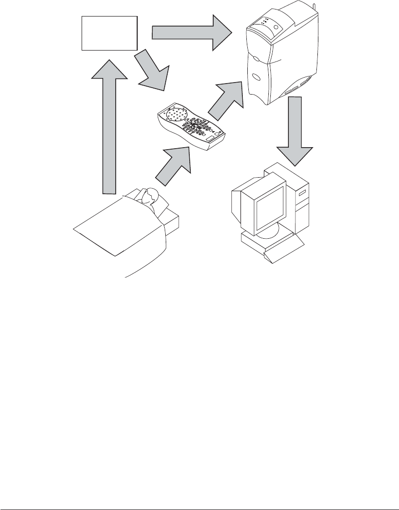
1.4.1 Data Flow through the Alice 5 Components
The flow of the data through the Alice 5 system is as follows: From the patient, the sensors pick
up physiologic events. Sensor cables carry the signal to the Alice 5 headbox or to an auxiliary
device.
If the data then gets carried to the Alice 5 base station via the headbox, the signal is amplified
and treated before being transformed from analog to digital format. If the signal is sent to the
base station via an auxiliary input, it is not amplified by the base station because it was already
amplified and conditioned in the auxiliary unit.
The signals are digitized and stored in the base station. If configured, they are then sent from the
base station to the computer running the Alice Sleepware diagnostic application.
Figure 1–2 illustrates the flow of data during an Alice 5 acquisition.
1–8
Alice
®
5 Setup and User’s Guide
Base Station
Headbox
Auxiliary
Device
(optional)
Computer Running
Alice Sleepware
Patient with
Sensors
Attached
Ethernet Connection
Figure 1–2 Data Flow During an Alice 5 Acquisition
1–9
Introduction
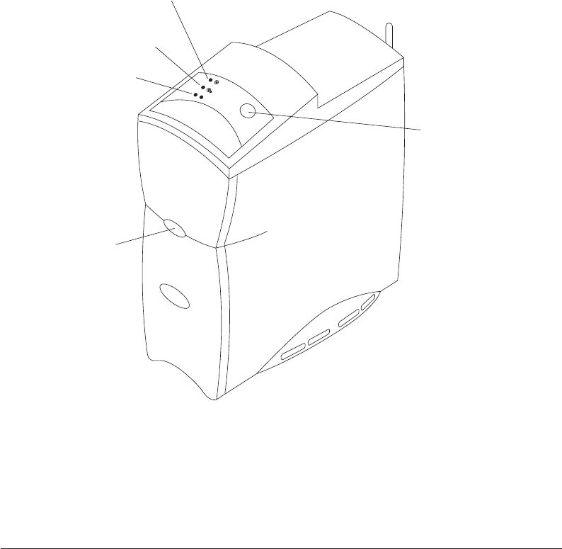
1.4.2 Alice 5 Base Station
The Alice 5 base station is a completely self-contained data collection device that is capable of
gathering and storing information without the use of an outside computer.
The base station should be placed on a flat, stable surface close enough to allow for easy connec-
tion to the headbox. The device should also be placed within easy access to an external AC power
source that is properly grounded.
Figure 1–3 shows the base station and its control panel.
Ready LED
Record LED
Audio/Video LED
Record Start/Stop
Button
Infrared
Transceiver
Figure 1–3 Alice 5 Base Station

1–10
Alice
®
5 Setup and User’s Guide
The control panel at the top of the base station has three LEDs:
1. Ready – The top LED is the power indicator and has the following states:
•Green – Indicates that power has been applied to the base station and it is ready for
operation.
•Yellow – Indicates that power has been applied to the base station, but it is not ready for
operation.
•Off – Indicates that power has not been supplied to the device.
2. Record – The center LED is the acquisition indicator and has the following states:
•Green – Indicates that a study is being recorded and there are no errors on the base station
or the headbox.
•Flashing Yellow – Indicates that the headbox has been disconnected while a study is in
progress. In this state, the base station records zeros until the headbox is reconnected.
•Off – Indicates that data is not being captured or recorded (i.e., a study is not in progress).
3. Audio/Video – The bottom LED is the camera/microphone recording indicator and has the
following states:
•Green – Indicates that video and/or sound is active or being recorded.
•Off – Indicates that video and sound are not active or being recorded.
In addition to the LEDs above, the control panel also includes the following button:
•Record Start/Stop – You can use this button to start or stop a data acquisition directly
from the base station. If you start an acquisition at the base station, the name and ID of
the previous patient is used, and the default configuration is recorded. For more informa-
tion on data acquisitions, see Chapter 4.
Note: Data acquisitions can also be started from a computer running Alice Sleepware. When
starting acquisitions from a computer, you can enter specific patient information.
The Infrared Transceiver on the front of the base station (shown in Figure 1–3) allows the base
station to communicate with a laptop computer. If you are using a laptop that does not have a
wireless card, the laptop can still communicate with the base station if it has infrared (IRDA)
capability.
1–11
Introduction
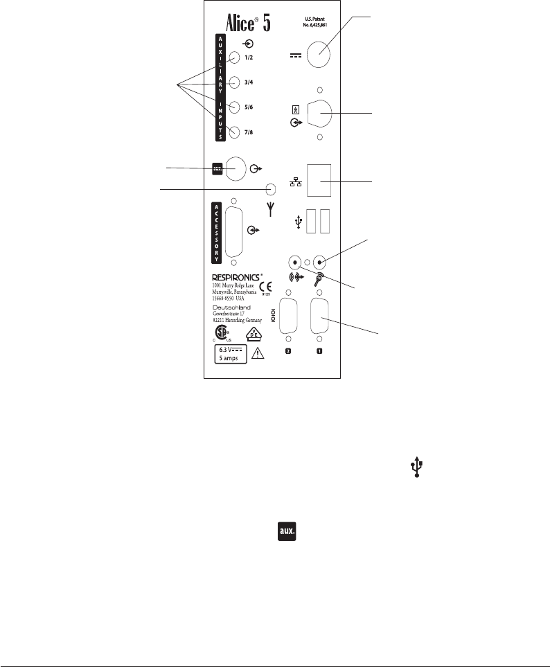
1.4.2.1 Base Station Rear Panel
Figure 1–4 shows the base station’s rear panel and its connections.
Power Supply
Headbox
Speakers
Microphone
Auxiliary Inputs
Ethernet
Connection
Antenna
COM 1 Serial Port
(for Respironics
therapy devices)
BNC Analog
Signal Connector
Figure 1–4 Base Station Rear Panel
Note: All other connections on the rear panel, including USB ports ( ), the Accessory port,
and the Com 2 Serial Connection port are not currently used.
Note: Do not connect a video camera to the port on the back of the base station. This is
a BNC analog signal connector, not a video input connector.
1–12
Alice
®
5 Setup and User’s Guide
On the back of the base station, there are two LEDs located on the ethernet connection ( ):
Network Present and Network Traffic. These LEDs function for both wired and wireless net-
works.
1. Network Traffic LED – The bottom LED has the following states:
•Flashing Green – Indicates that there is traffic on the network.
•Off – Indicates that there is no traffic on the network.
2. Network Present LED – The top LED has the following states:
•Flashing Yellow – Indicates that the only connection is to a wireless network.
•Green – Indicates that the network is a wired network.
•Off – Indicates that a network is not present.
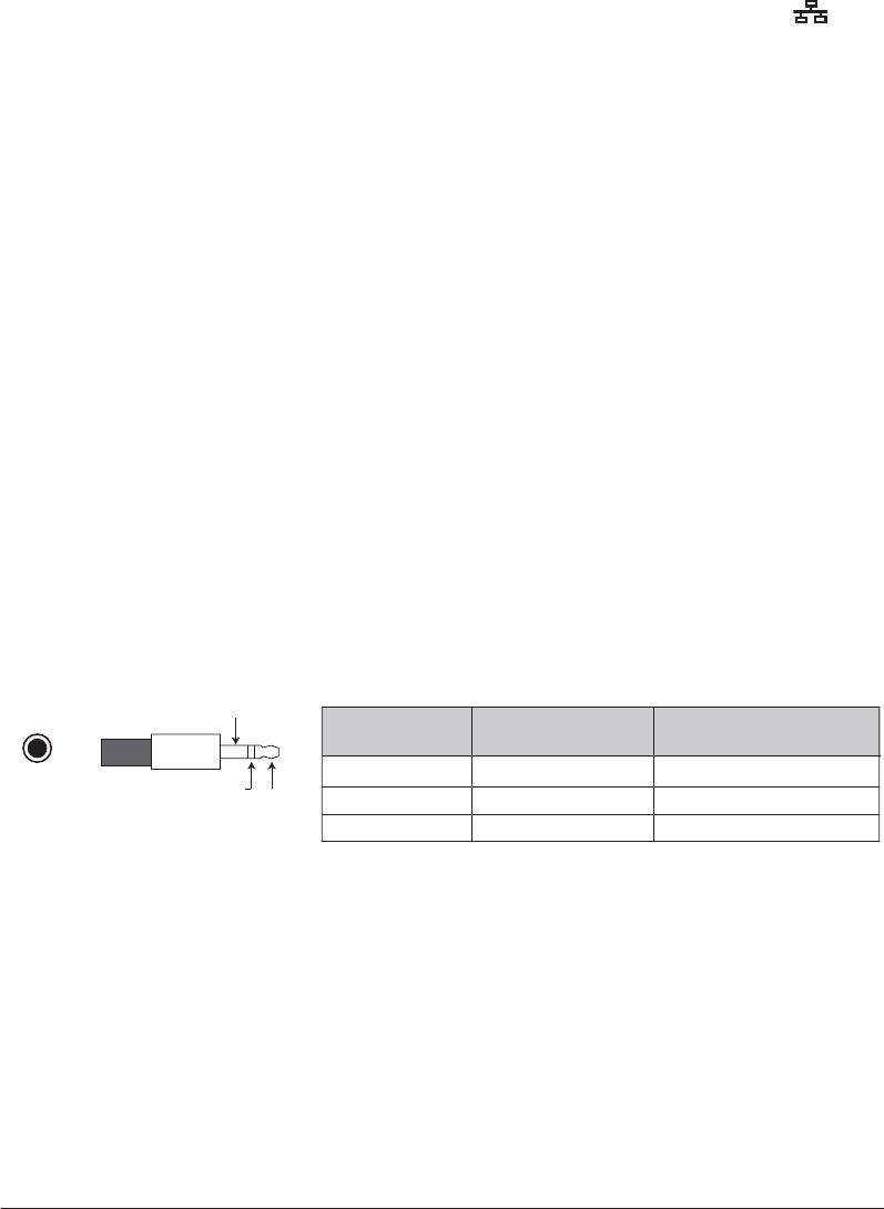
Auxiliary Input Ports
You can connect additional external medical devices using the auxiliary inputs on the back of the
base station. There are four ports available, but you can use a channel splitter to attach two
devices to each input. See the Respironics Diagnostic Accessory Guide for additional information
on using a channel splitter with the Alice 5.
The following table contains the pin-out information for the auxiliary input ports. The table is
specific to auxiliary inputs 1 and 2, but you can use the same information for the remaining
inputs (3/4, 5/6, etc.), respectively.
Pin Number Pin Name Input/Output/Power
1 Tip
2 Ring
3 Sleeve
Aux 2 Input (even)
Aux 1 Input (odd)
Rtn
In
In
GND
3.5 mm
Plug
(3)
Sleeve
(2)
Ring (1)
Tip
Auxiliary Ports 1 and 2

1–13
Introduction
Serial Connection Port
You can connect Respironics CPAP or bi-level therapy devices to the Com 1 serial port on the
back of the base station. The following table contains the proper pin-out information for the serial
connection port.
Note: Contact Respironics Customer Service for a list of the therapy devices that are
compatible with Alice 5.
12345
6789
Pin Number Pin Name Input/Output/Power
1
2
3
4
5
6
7
8
9
CD
RxD
TxD
DTR
GND
DSR
RTS
CTS
RI
In
In
Out
Out
GND
In
Out
In
In
1–14
Alice
®
5 Setup and User’s Guide
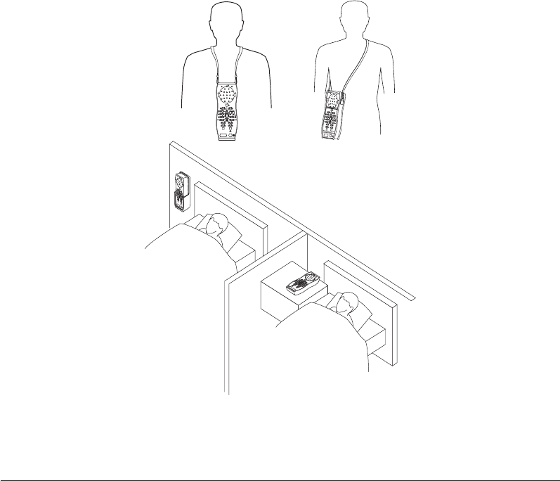
1.4.3 Headbox
The Alice 5 headbox combines the neurological inputs and cardio-respiratory inputs into a single
device. These signals are then sent to the Alice 5 base station. You can place the headbox in
several different locations:
•On a table or stand beside the patient’s head.
•In the headbox mounting bracket attached to the wall behind the patient’s head.
•Attached to a carrying strap that the patient can wear around the neck. This option is
useful if the patient needs to get up during the study so the connectors do not need
removed.
•In the headbox pouch attached to a shoulder strap worn over the patient’s shoulder.
Figure 1–5 illustrates the options for headbox placement.
Figure 1–5 Headbox Placement Options
1–15
Introduction
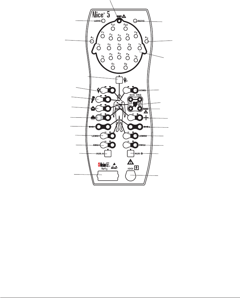
Figure 1–6 shows the Alice 5 headbox and defines the connections.
Serial Connection
to the base station
Oximeter
Connection
Auxiliary Input Auxiliary Input
Spare EMG Spare EMG
Leg EMG Leg EMG
Actimeter Actimeter
Abdominal Effort Belt Body Position Sensor
Chest Effort Belt
Snore Sensor
Thermistor Flow Sensor
Pressure-Based
Flow Sensor
Chin EMG
ECG/EKG
EEG
A1 Reference
Electrode
Left EOG Right EOG
A2 Reference
Electrode
Ground Connection*
Ground Connection*
Figure 1–6 Alice 5 Headbox
* Note: Although there are two ground (GND) connections, you can only use one ground
connection at a time. You cannot use both simultaneously.
Note: For EEG inputs, connect the left reference electrode to the A1 input jack on the left
side of the device. Connect the right reference electrode to the A2 input jack on the
right side of the device.
See Chapter 4 for more information on connecting sensors to the headbox.
1–16
Alice
®
5 Setup and User’s Guide
1.5 Symbol Key
The following symbols appear on the Alice 5 base station and headbox.
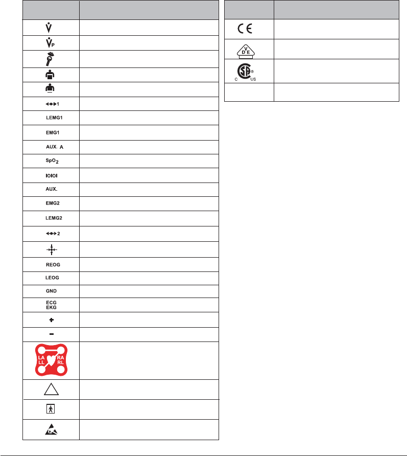
1.5.1 Headbox Symbols
Thermistor Flow Sensor
Pressure Based Flow Sensor
Chest Effort Belt
Abdominal Effort Belt
Actimeter Sensor
Leg EMG Sensor
Spare EMG Sensor
Auxiliary Input Sensor
Oximeter Sensor
Serial Connection to Base Station
Auxiliary Input Sensor
Spare EMG Sensor
Leg EMG Sensor
Actimeter Sensor
Body Position Sensor
Right EOG Sensor
Left EOG Sensor
Ground
Left Arm Sensor
Electrocardiogram Sensor
Left Leg Sensor
Right Arm Sensor
Right Leg Sensor
Positive
Negative
Snore Sensor (Vibration Sensor)
Type BF Applied Part
Symbol Description
!
Attention, consult accompanying documents
B
Electrostatic Discharge
European CE Declaration of Conformity
Notified Body Approval for
Standards Compliance
Canadian/US Certification
0123
IPX1 Drip Proof Equipment
Front
Symbol Description
Back
1–17
Introduction
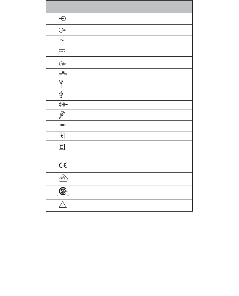
1.5.2 Base Station Back Panel Symbols
!Attention, consult accompanying documents
European CE Declaration of Conformity
Notified Body Approval for Standards Compliance
Canadian/US Certification
0123
Input
Input/Output (on back panel) (connect to headbox)
USB Port
(connector)
Connect Speaker (out)
Serial Connection to PC or CPAP
Connect Microphone (in)
Ambient Sound Recording and /or Intercom
Antenna
Network
Output
DC Power
Type BF Applied Part
Symbol Description
IPX0
Ordinary Equipment Rating
Class II (Double Insulated)
AC Power

1–18
Alice
®
5 Setup and User’s Guide
1.5.3 Base Station Control Panel Symbols
Ready
(When green - Power is supplied, and the acquisition is ready to start)
(When yellow - Power is supplied, but acquisition setup is not complete)
Recording
(When green - Acquisition is proceeding without errors)
(When flashing yellow - Acquisition setup is not complete)
Record Start/Stop Button
Audio/Video
(When green - Video / Audio is being recorded and/or the intercom is active)
Symbol Description
1.6 Acronyms and Definitions
The following terms and acronyms appear in this manual:
Acquisition A collection of polysomnographic data that has been acquired
during a patient study.
Ad-Hoc Network An Ad-hoc Wireless Local Area Network (WLAN) is a group of
devices, each with a WLAN adaptor, connected as an independent
wireless LAN.
Alice Sleepware The Respironics software application that runs via the Windows
operating system and that receives and analyzes physiologic data
from Alice equipment.
Alice Sleepware Starter Bar The component of the Alice Sleepware that appears at the top of
the computer screen and is used during equipment setup for
configuration and during data acquisitions to view settings or
control the optional microphone and camera.
Base Station Part of the Alice system equipment used to store
polysomnographic data collected by the Alice headbox. This data
can then be copied/moved to a computer for use with the Alice
Sleepware software.
BiPAP Bi-Level Positive Airway Pressure
CA Central apnea – A temporary cessation of airflow accompanying a
cessation of respiratory effort.

1–19
Introduction
CPAP Continuous Positive Airway Pressure
Configuration The set of channels used to acquire polysomnographic data.
ECG Electrocardiogram – A recording of cardiac electrical activity. In
sleep testing, this channel is used to assess heart rate and rhythm.
EEG Electroencephalogram – A recording of electrical brain activity.
With the EMG and EOG, the EEG is one of three basic variables
used to score wake and sleep and to identify sleep stages. The EEG
is the primary variable for sleep staging.
EMG Electromyelogram – A recording of muscle electrical activity. The
chin EMG is measured by surface electrodes, and along with the
EEG and EOG, it is one of the three basic variables used to score
wake and sleep and to identify sleep stages.
EOG Electrooculogram – A recording of voltage changes resulting from
shifts in position of the eye. Along with the EEG and EMG, the
EOG is one of the three basic variables used to score wake and
sleep and to identify sleep stages.
EPAP Expiratory Positive Airway Pressure
EtCO2End tidal carbon dioxide, as detected by an end tidal CO2 monitor-
ing device.
Generic Channels Channels whose data the Alice 5 does not have an auto-scoring
algorithm for. Generic channels need definition regarding their
presentation (display). Generic channels usually have as their
source an auxiliary device connected to an auxiliary input on the
Alice headbox. Generic channels may be displayed as numbers or
graphs. There are three display types for generic channels:
Graphic, Grapho-Numeric, and Numeric.
Graphic Display Type One of three display types for generic channels. A graphic display
type is assigned when a channel’s data is most useful to the
clinician when displayed as a graph (waveform) rather than a
number, and the data points of the curve are not clinically useful.
In other words, the curve, not its data points, are important.
Grapho-Numeric Display Type
One of three display types for generic channels. A grapho-numeric
display type is assigned when a channel’s data is most useful to the
clinician when displayed as a graph (waveform) and the data points
are also meaningful.
Headbox A bedside remote amplifier that is part of the Alice system and is
used to collect physiologic data from sensors placed on the
patient’s body.

1–20
Alice
®
5 Setup and User’s Guide
Infrastructure Network An integrated wireless and wired LAN is called an infrastructure
configuration.
IPAP Inspiratory Positive Airway Pressure
IR Infrared
LAN Local Area Network
LED Light Emitting Diode
MAC Address Media Access Control address. This is a unique hardware address
that identifies a device on a network. It is assigned by the manufac-
turer and cannot be changed. This address can usually be found on
the device packaging.
Montage A montage (as distinguished from an acquisition configuration) is a
way to display re-referenced EEG and EOG data during or after an
acquisition. Each acquired EEG channel measures the difference in
electrical potential between a given (active) electrode and a
reference. The montage tool recombines EEG/EOG data in order to
display the difference in potential between any two electrodes.
Numeric Display Type One of the three display types for generic channels. A numeric
display type is assigned when the data is most useful to the
clinician when displayed as a number, rather than a waveform.
OSA Obstructive Sleep Apnea – A temporary cessation of airflow
without an accompanying cessation of respiratory effort.
pH A measure of the acidity or alkalinity of a fluid. In sleep, this
generally refers to a measure of the acidity of fluid in the esopha-
gus, detected by an esophageal pH probe.
PLM Periodic limb movement, indicated by the change in leg muscle
tone as detected by the difference in electrical potential of two leg
EMG leads.
Polysomnography Recording of multiple channels of physiologic data during sleep.
PSG Polysomnography
PTT Pulse Transit Time
REM Rapid Eye Movement – The stage of sleep with the highest brain
activity, characterized by enhanced brain metabolism and vivid
hallucinations, imagery, and dreams. During the REM stage,
resting muscle activity is suppressed and there is a high awakening
threshold to nonsignificant stimuli.
SpO2Arterial oxygen saturation level via pulse oximetry.

1–21
Introduction
Wi-Fi Wireless Fidelity; generically refers to any type of 802.11 network.
Any devices tested and approved as “Wi-Fi Certified” by the Wi-Fi
Alliance are certified as interoperable with each other.
1.7 Contacting Customer Service
If you need product support, call the Respironics Customer Service department at 1-800-345-
6443 (US or Canada only) and 1-724-387-4000.
Additionally, you may contact Respironics Customer Service at the following email address:
service@respironics.com

1–22
Alice
®
5 Setup and User’s Guide

2–1
Alice 5 Equipment Setup
CHAPTER
2
Alice 5 Equipment Setup
This chapter describes how to connect the hardware components included with the Alice 5
system. It contains graphics illustrating the connections as well as detailed step-by-step instruc-
tions.
There are several possible ways to set up your Alice 5 system:
•Wired point-to-point setup, where wired devices communicate directly with each other
(e.g., base station to computer).
•Wired network setup, where a switch is used to connect multiple devices to a Local
Area Network (LAN).
•Wireless ad-hoc setup, a wireless networking framework in which devices communicate
directly with each other, without the use of an access point.
•Wireless Access Point Infrastructure network setup, where a device acts as a commu-
nication hub for users of a wireless device to connect to a wired LAN.
This chapter provides general instructions on how to set up each of these systems. The examples
provided are suggested ways of positioning the equipment. You may alter the component setup as
needed.

2–2
Alice
®
5 Setup and User’s Guide
2.1 Before You Begin
Before you set up your Alice 5 system, keep the following information in mind:
•Map out your facility’s layout in advance so you know what type of equipment, cables,
and accessories you will need.
•Determine whether you will be setting up a wired or wireless network for Alice 5. If you
will have a wired network with multiple devices connected, you will need a switch.
•Respironics recommends that you set up the Alice system on its own network, indepen-
dent of your facility’s network(s). System performance may be better on an independent
network.
•Your cabling requirements will change depending on whether you use a point-to-point
setup or a network setup. You will need a CAT-5 Crossover cable for a point-to-point
setup, while a network setup requires a standard CAT-5 Patch cable.
•The Alice 5 system does not support the Dynamic Host Configuration Protocol (DHCP),
a protocol for assigning dynamic IP addresses to devices on a network. You must assign
static IP addresses to your Alice 5 devices and to the computers you are running the Alice
Sleepware software on, as well as to any network video cameras or servers you use. See
Chapter 3, Software Installation and Setup, for additional information.
2.2 Setting Up Your Network
This section describes how to install your system using wired or wireless networks.
2.2.1 Network Setup Examples
This section provides example illustrations of various setups that are commonly used when
configuring Alice 5 networks. There are many possible configurations, but these will help you
understand some of the basic connections and how the IP addresses are set up. The different
wired and wireless setups are described in greater detail in Sections 2.2.2 – 2.2.4.
Note: It’s recommended that you first map your network setup before proceeding with the
equipment installation instructions later in this chapter and the software installation
described in Chapter 3. You will need to determine what your network configuration is
and what equipment you’ll be using (if you’ll need a switch, a video server, etc.) before
you start setting everything up.

2–3
Alice 5 Equipment Setup
Example 1
192.168.1.1
192.168.1.2
Network
Switch
Alice 5
Base Station
Workstation
192.168.1.1 192.168.1.2
Alice 5
Base Station
Workstation
- CAT-5 Patch Cable
C5P
C5P
C5P
C5X
- CAT-5 Crossover Cable
C5X
Figure 2–1 Basic Wired Network Setup Using a Switch or a Crossover Cable
Note: The IP addresses shown in Figures 2–1 through 2–4 are only examples. You will need
to assign IP addresses that are appropriate for your facility’s network.
Example 2
Alice 5
Base Station
Workstation
Video Server
Video Camera
192.168.1.1
192.168.1.2
192.168.1.3
Network
Switch
- CAT-5 Patch Cable
C5P
C5P
C5P
C5P
Figure 2–2 Wired Network with Video Server and Camera
2–4
Alice
®
5 Setup and User’s Guide
Example 3
Alice 5
Base Station
Workstation
Video Server
Video Camera
169.254.1.11
192.168.1.2
192.168.1.3
169.254.1.2
C5X
- CAT-5 Crossover Cable
C5X
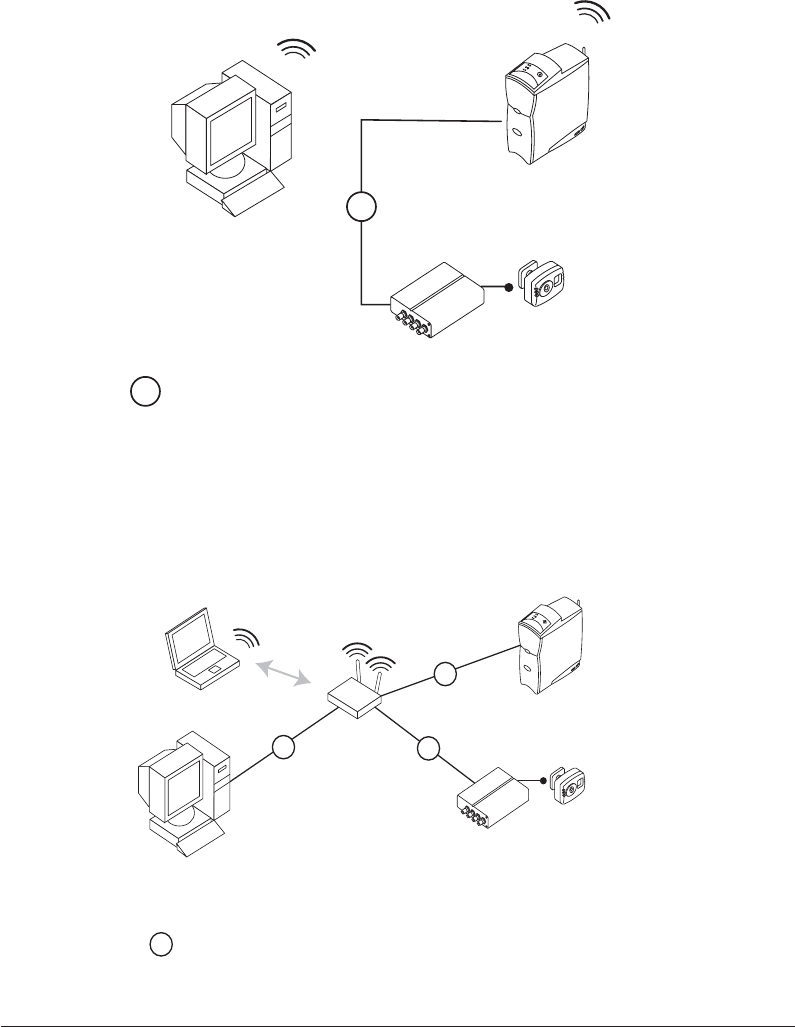
Figure 2–3 Network Setup with Wireless Desktop
Example 4
Alice 5
Base Station
Video Server
Video Camera
192.168.1.11
192.168.1.2
192.168.1.3
Laptop
Wireless
Access Point
192.168.1.1
192.168.1.100
Workstation
- CAT-5 Patch Cable
C5P
C5P C5P
C5P
Figure 2–4 Access Point Infrastructure Network Setup
2–5
Alice 5 Equipment Setup
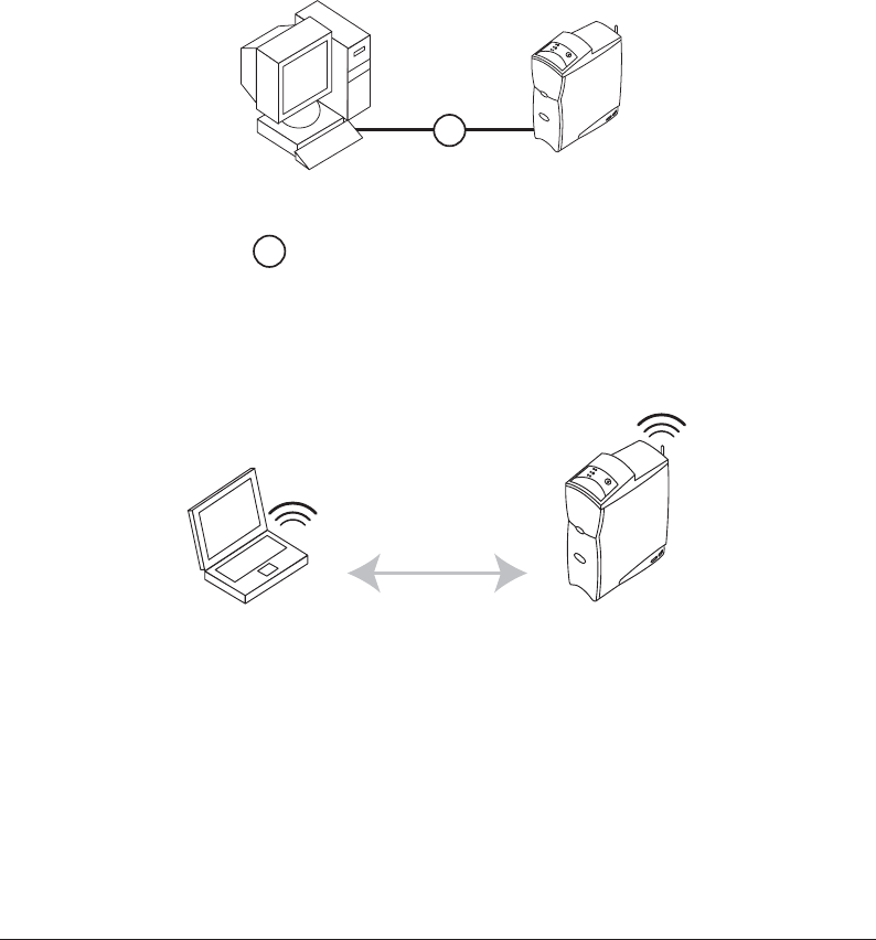
2.2.2 Using a Point-to-Point Setup
If you plan to connect the Alice 5 base station directly to the computer you will be using to view
data, you may want to use a point-to-point wired setup or an ad-hoc wireless setup to install the
equipment.
Figures 2–5 and 2–6 show point-to-point and ad-hoc setup connections. In Figure 2–5, one
desktop computer is directly connected to an Alice 5 device using a CAT-5 crossover ethernet
cable.
Workstation Alice 5
Base Station
C5X
- CAT-5 Crossover Cable
C5X
Figure 2–5 Wired Point-to-Point Setup
In Figure 2–6, a laptop is connected to the Alice 5 device wirelessly via an ad-hoc setup.
Alice 5
Base Station
WIFI
Connection
Laptop
w/WIFI Card
Figure 2–6 Wireless Ad-Hoc Setup

2–6
Alice
®
5 Setup and User’s Guide
2.2.2.1 Map Your Facility’s Network Setup
You can use the space on this page to map out your facility’s network configuration and the IP
addresses for each piece of equipment.
2–7
Alice 5 Equipment Setup
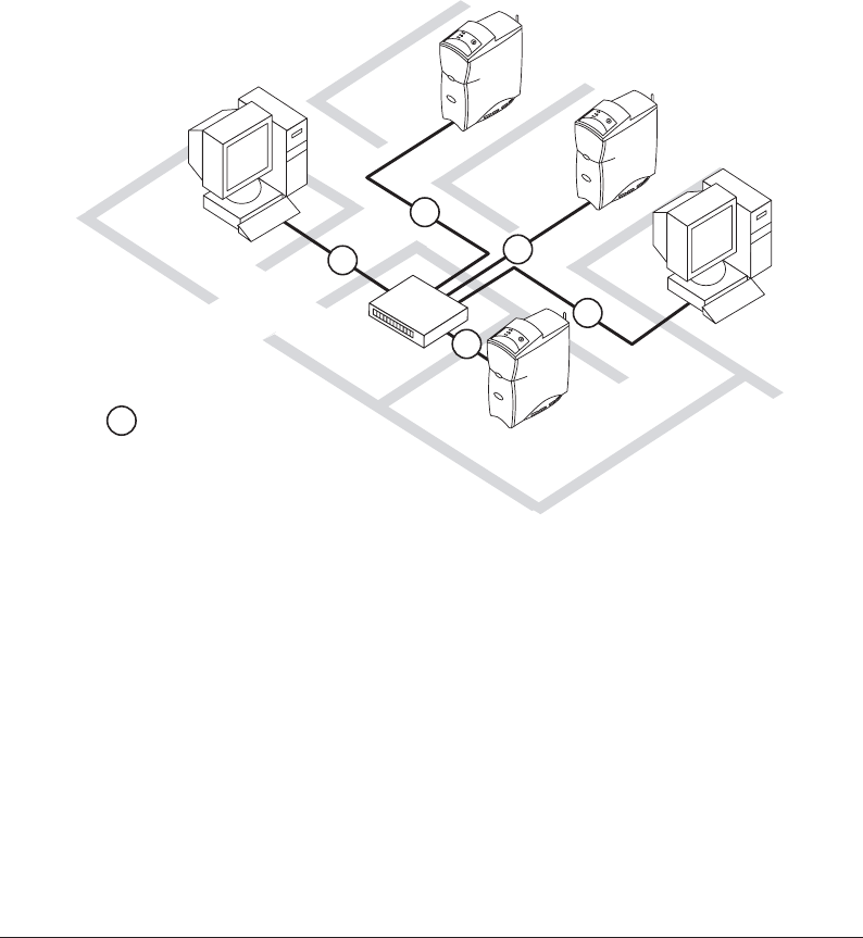
2.2.3 Using a Wired Network Setup
If you plan to have several patient rooms and several Alice 5 systems or computers, you may
want to set your equipment up using a wired network setup. Figure 2–7 provides an example.
Note:Refer to IEC 60601-1-1 for definition of the patient environment.
Control Room
Bedroom 1
Bedroom 2
Bedroom 3
Network
Switch
Workstation
- CAT-5 Patch Cable
C5P
C5P
C5P
C5P
C5P
C5P
Figure 2–7 Wired Network Setup
2–8
Alice
®
5 Setup and User’s Guide
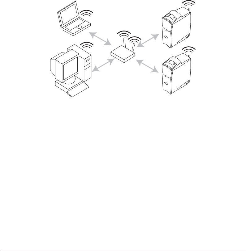
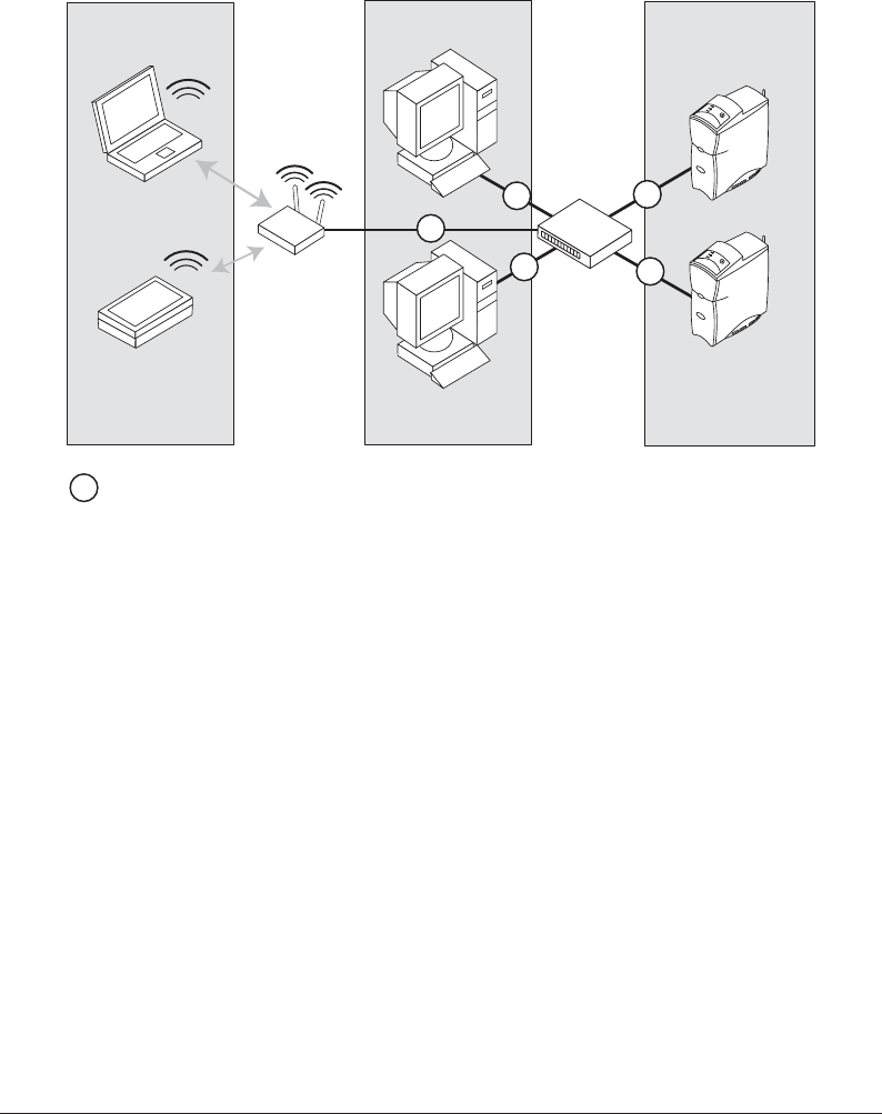
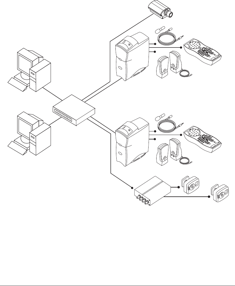
2.2.4 Using an Access Point Infrastructure Network
If you plan to have multiple patient rooms with several Alice 5 systems and computers and you
want to connect a portion or all of your network wirelessly, you can use an Access Point Infra-
structure network. Figures 2–8 and 2–9 show examples of possible setups.
Figure 2–8 shows a network in which multiple computers are connected to multiple Alice 5
devices through a wireless access point.
Laptop
w/WIFI Card
Alice 5
Base Station
Alice 5
Base Station
Wireless
Access Point
Workstation
w/WIFI Card
Figure 2–8 Access Point Infrastructure Network Setup – Example 1
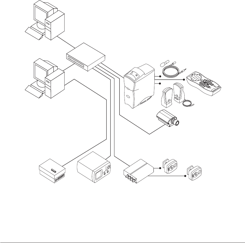
Figure 2–9 shows a network in which multiple computers are connected to an Access Point
wirelessly, but the Alice 5 devices are connected to the network switch using ethernet cables, and
the switch is connected to the Access Point using an ethernet cable.
2–9
Alice 5 Equipment Setup
Laptop
w/WIFI Card
Wireless
Access Point
Base Station
Base Station
Network
Workstation
Workstation
Switch
Bedrooms
Wireless Devices Control Rooms
Tablet PC
- CAT-5 Patch Cable
C5P
C5P
C5P C5P
C5P C5P
Figure 2–9 Access Point Infrastructure Network Setup – Example 2
2–10
Alice
®
5 Setup and User’s Guide
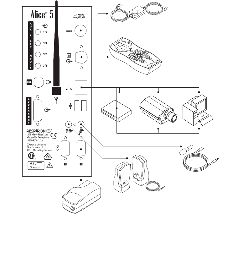
Power Supply
Headbox
Speakers
Respironics
Therapy Device*
Microphone
Video Camera*Network Switch* Workstation*
* Additional equipment not included with your Alice 5 System
2.2.5 Connecting the Alice 5 Hardware Components
Once you have determined which type of setup you will be using (point-to-point, ad-hoc, wired
network, or access point infrastructure network), you can connect your Alice 5 equipment.
Figure 2–10 provides a detailed illustration of how different devices and cables are connected to
the back panel of the base station. The steps that follow refer to many of the connectors shown in
Figure 2–10.
Figure 2–10 Base Station Back Panel
2–11
Alice 5 Equipment Setup
Complete the following steps to set up your Alice 5 hardware. Refer to Figure 2–12 for a detailed
example of how the final room setup might look.
1. If you haven’t already done so, unpack your computer and set it up according to the instruc-
tions supplied with it.
2. Unpack your Alice 5 system and make sure that all of the components are included.
3. Make sure that the base station is placed on a flat, stable surface close enough to allow for
easy connection to the headbox. The base station should also be placed within easy access to
an external AC power supply that is properly grounded.
4. Place the headbox on a table or stand above and behind the patient’s head, beside the patient’s
pillow, or on a nearby hook using the carrying strap supplied with your system. Or, use the
mounting bracket to mount the headbox on a wall.
5. Connect the power cord to the AC power supply.
6. Plug the pronged end of the power cord into a wall outlet.
Caution: Never use an extension cord with the Alice 5 system. Always operate the device
using a properly grounded AC power outlet. If you are unsure whether a power
outlet is properly grounded, contact an electrician for assistance.
7. Connect the power supply’s cord into the Power Connector port ( ) on the back of the
base station.
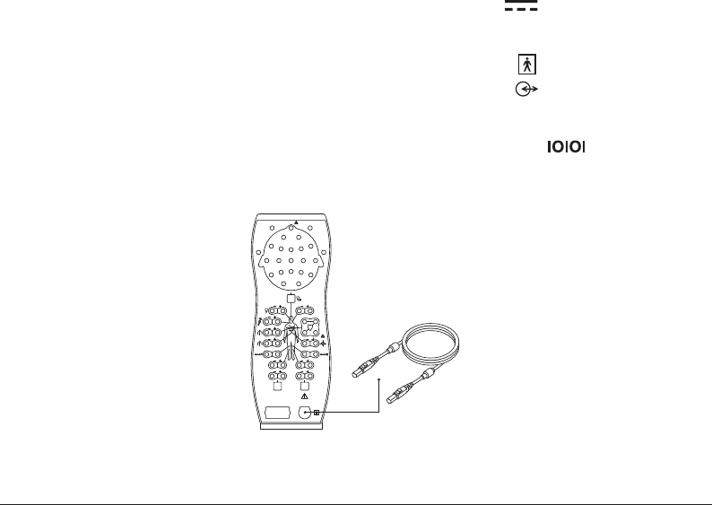
8. Plug one end of the Patient Cable into the headbox connector port ( ) on the back of the
base station.
9. Plug the remaining end of the Patient Cable into the Serial Connection ( ) on the head-
box (as shown in Figure 2–11).
Patient
Cable
Figure 2–11 Patient Cable Connection

2–12
Alice
®
5 Setup and User’s Guide
Note: The ends of the Patient Cable are interchangeable. It does not matter which end you
plug into the base station and which end you plug into the headbox.
10. Follow Step A for point-to-point wired setups, Step B for wired network setups, or Step C for
ad-hoc or access point infrastructure setups.
A. For Point-to-Point Wired Setups:
–Plug a CAT-5 crossover cable into the Network port ( ) on the back of the base
station.
–Then, plug the remaining end of the cable to your computer’s network interface
connector.
B. For Wired Network Setups:
–Plug a standard CAT-5 Patch cable into the Network port ( ) on the back of the
base station.
–Then, plug the remaining end of the cable into an ethernet connection. For example,
if you have set up your network switch in your control room, you can run the CAT-5
Patch cables from the base stations in each patient room to the ethernet connectors
on the switch, so that all base stations are plugged into the same network.
–To connect your computer to the network, plug a CAT-5 Patch cable into your
computer’s network interface connector, and plug the other end of the cable into an
ethernet connection (e.g., a connector on a switch).
C. For Wireless Ad-hoc or Access Point Infrastructure Setups:
–Plug a standard CAT-5 Patch cable into the Network port ( ) on the back of the
base station.
–Then, plug the remaining end of the cable into an ethernet connection.
Note: In Step C, although you are configuring a wireless setup, you still need to perform this
step when initially setting up your Alice 5 system. For network security reasons, the
wireless feature is disabled when you first receive your Alice 5 device. In order to
enable the wireless feature, you must first set up the device as a wired connection to
allow your device to be seen on the network. Then, after you enable the wireless
feature via the Sleepware software, remove the ethernet cable. Once the wireless
feature is enabled, the system uses the wireless antenna attached to the Antenna
connector ( ) on the back of the base station to transmit data.
11. If you are using a microphone for intercom/ambient sound recording, plug the male end of the
Microphone cable into the Microphone connector ( ) on the back of the base station. Plug
the remaining end of the Microphone cable into the microphone you are using on the patient.

2–13
Alice 5 Equipment Setup
Note: Once you install Sleepware and add your Alice devices (as described in Chapter 3),
you can enable the audio feature by right-clicking on the Room button located on the
Starter bar and selecting Audio/Video Settings from the drop-down menu. See Section
2.4, Adding Accessories, for instructions on setting the audio and video settings.
12. If you are using speakers with your system, connect the green, male end of the Speaker cable
into the Speaker Connector ( ) on the back of the base station. Connect the other end of
the cable directly into any basic-powered PC computer speaker.
Note: If the technician is in a control room separate from the sleep lab, the speakers and
microphone allow the technician to speak directly with the patient from the control
room. The speakers and microphone work in the same one-way format as an intercom.
Once you’ve installed the speakers, if you want to change the volume, you can adjust the
volume control on the speakers or you can use the volume control setting on your computer.
13. To connect a Respironics therapy device (CPAP, Bi-Level, etc.) to the Alice 5 system, connect
the serial connector end of the therapy device’s Communications Cable into the Com 1 Serial
Connection port ( ) on the back of the base station. Connect the remaining end of the
Communications Cable to the port on the back of the therapy device or to the Sleeplink card,
if applicable. This allows you to control the therapy device directly through the Alice 5
system. Refer to the therapy device’s manual for connection information.
14. If desired, you can connect additional external medical devices, produced by other manufac-
turers, using the Auxiliary Input connectors on the back of the base station. Refer to these
devices’ manuals for additional information.
Note: All other connectors on the base station (USB ports, Accessory ports, the Auxiliary
channel, and the Com 2 Serial Connection port) are not currently used.
15. Install the Alice Sleepware software using the instructions found in Chapter 3.
2–14
Alice
®
5 Setup and User’s Guide
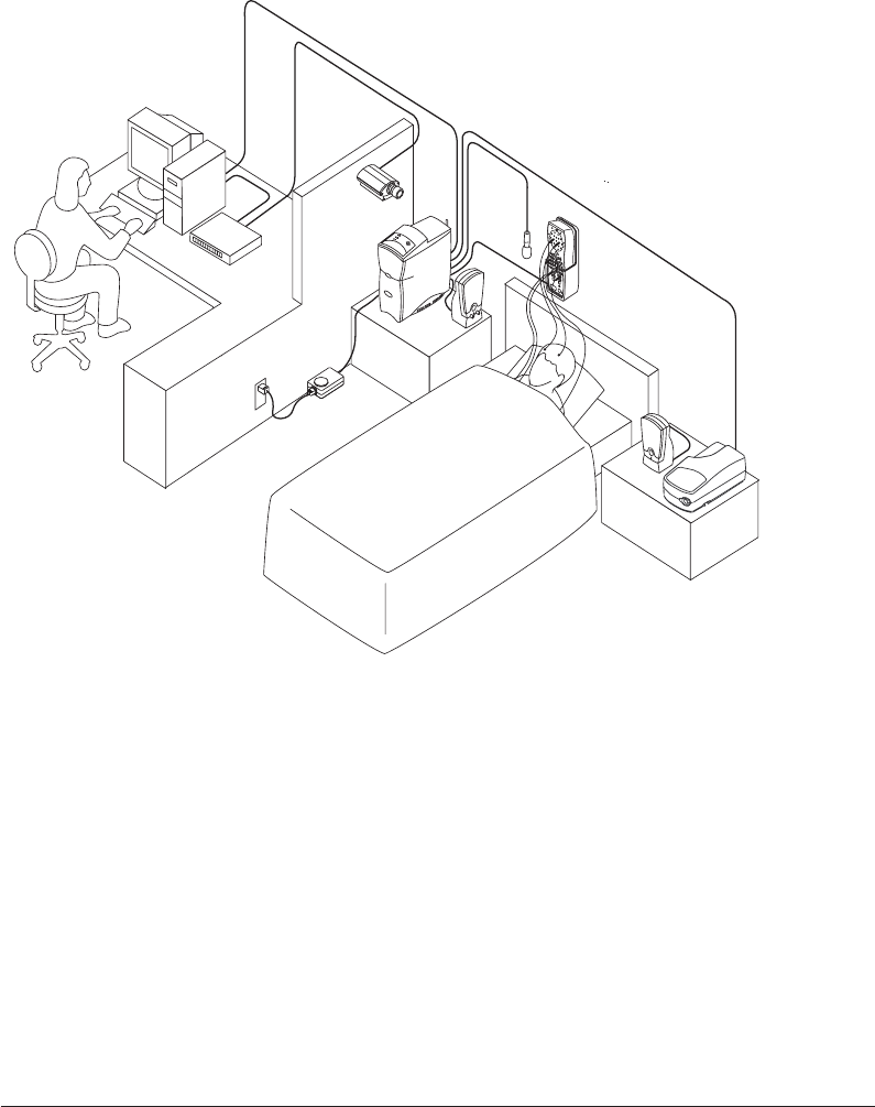
Figures 2–12 and 2–13 provide a more detailed example of how a network setup may look.
Power
Supply
Headbox
Speakers
Microphone
Base
Station
Video
Camera*
Network
Switch*
Workstation*
Respironics
Therapy Device*
* Additional equipment not included with your Alice 5 System
Figure 2–12 Detailed Wired Network Setup – Single Bedroom
2–15
Alice 5 Equipment Setup
Wo rkstation*
Wo rkstation Headbox
Speakers
Microphone
Headbox
Speakers
Microphone
Base Station 2
Base Station 1
BEDROOM 1
BEDROOM 2
CONTROL ROOM
Video Camera*
Network
Switch*
Video Server* Video Cameras*
* Additional equipment not included with your Alice 5 system.
Figure 2–13 Detailed Wired Network Setup – Multiple Bedrooms
2–16
Alice
®
5 Setup and User’s Guide
2.3 Integrating Alice 3 and Alice 4 Devices
into your Alice 5 Network
You can connect Alice 3 and Alice 4 devices to your network and use them in combination with
Alice 5 devices and Alice Sleepware.
Figure 2–14 illustrates how these devices might be incorporated into your network.
Workstation
Workstation
Video ServerAlice 4
Base Station
Alice 3 (Calvin)
Base Station Video Cameras
Headbox
Speakers
Microphone
Base Station 2
BEDROOM
CONTROL ROOM
Video Camera
Network
Switch
Figure 2–14 Sample Network Containing Alice 3 and Alice 4 Devices

2–17
Alice 5 Equipment Setup
2.4 Adding Accessories
There are many additional accessories you can use with the Alice 5 system. See the Respironics
Diagnostic Accessory Guide for details on the many accessories available.
This section provides instructions on how to set up video cameras and video servers with the
Alice 5.
2.4.1 Installing Video Cameras and/or Video Servers
You may want to install video cameras and/or video servers to use with your Alice system. There
are a few setup options when using video cameras with the Alice 5 system:
•Connect a video camera directly to the base station if your Alice 5 equipment is commu-
nicating with your computer through a wireless interface.
•Connect a video camera to a switch on your network.
•Connect multiple video cameras (up to four) to a video server that is connected to your
network’s switch or hub. You must be using a network switch with your Alice 5 system to
use a video server.
Note: If your computer is wired to the base station, or if you are using a network switch that
is wired to the base station, you cannot connect a camera directly to the Alice 5
device.
Note: See the Respironics Diagnostic Accessory Guide to determine what video server is
compatible with the Alice 5 System and to order video cameras if needed. Refer to the
instructions included with your video server for more detailed product information.
Decide which option you want to use, and then follow the installation instructions below.
1. Connect your video equipment to the Alice 5 system using one of the following three configu-
rations:
a. If you are connecting a video camera directly to the base station, connect a CAT-5
crossover cable to the network connector on the video camera, and connect the other end
of the cable to the Network port ( ) on the back of the base station.
b. If you are connecting a video camera to your network switch, connect a CAT-5 patch
cable to the network connector on the video camera, and connect the other end of the
cable to one of the ports on your switch.
c. If you are connecting one or more video cameras to a video server:
–Connect a CAT-5 patch cable to the network connector on the rear panel on the video
server, and then connect the other end of the cable to an ethernet connection on your
switch.

2–18
Alice
®
5 Setup and User’s Guide
–If your camera has a BNC connector on it, connect a coaxial video cable to one of
the video inputs (BNC connectors) on the front panel of the video server, and
connect the other end of the cable to the BNC connector on the camera. Repeat this
step if you are adding more than one camera.
Video Inputs
(BNC Connectors)
Network
Connector
Figure 2–15 Video Server Front and Rear Panel Connections
Note: If your camera does not have a BNC connector and has a standard phono-type RCA
connector instead, you will need a BNC-to-RCA converter to connect the camera to the
video server.
2. Note the serial number on your video camera or on the bottom of the video server if you are
using the server. You need to know this to set the IP address.
Note: If you are using a video server, you only need to assign the server an IP address, not
the cameras. However, if you are connecting a camera directly to the base station or to
a switch, assign an IP address to the camera.
Note: The serial number on the video equipment is the same as the MAC/Ethernet address
you will enter in step 3 below (e.g., 00408c100086 = 00-40-8c-10-00-86).
3. From a computer on your network, assign the video camera or video server (depending on
your setup) a unique IP address:
•From your Windows operating system, start a DOS window by going to Start>Run and
typing cmd in the text box that appears. Click OK to access DOS.
•Type the following command in the window that appears:

2–19
Alice 5 Equipment Setup
Syntax:
arp -s <Video Camera or Server IP address> <MAC/Ethernet address>
For example:
arp -s 172.21.1.200 00-40-8c-10-00-86
•Press Enter, and on the next line, type the following command:
Syntax:
ping -t <Video Camera or Server IP address>
For example:
ping -t 172.21.1.200
4. You will now see “Request timed out” messages repeatedly appearing in the window.
Note: If the “Request Timed Out” messages do not appear, and the message “Destination
Host Unreachable” appears instead, then the video equipment is not accessible on
your subnet. Refer to Chapter 7, Troubleshooting, for information on how to resolve
this problem.
5. Connect the power supply to the video camera or server.
Note: If you connected the power supply before entering the DOS commands, unplug it and
reconnect it at this time.
6. Approximately 25 seconds after connecting the power supply, the message
“Reply from <Video Camera or Server IP address>” appears. If using the video server, make
sure the power indicator on the front panel of the server is permanently lit and that the
network indicator flashes intermittently.
Note: If you do not receive the “Reply from...” message, refer to Chapter 7, Troubleshooting,
for information on how to correct the problem.
7. Exit ping. The installation is complete, and you are ready to access the video camera(s) from
your browser.
Note: The remaining steps in this section explain how to enable video through Alice Sleep-
ware once you have installed the software. For instructions on software installation,
see Chapter 3.
2–20
Alice
®
5 Setup and User’s Guide
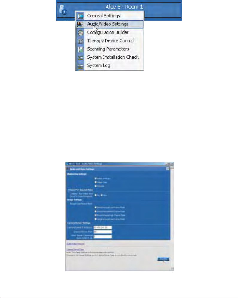
8. To enable the video feature through Alice Sleepware, go to your Starter Bar, right-click on the
Room button, and select Audio/Video Settings from the drop-down menu, as shown in Figure
2–16.
Figure 2–16 Accessing the Audio/Video Settings
9. Choose your multimedia and image settings in the screen shown in Figure 2–17.
10. In the Camera/Server settings, type in the IP address of the video camera or video server and
the port number that the video camera is connected to (Port # 1-4 if using the video server).
Note: The Camera/Server Port number will always be 80.
Note: See the Alice Sleepware User’s Guide for more information on these settings and for
details on how to view and save video, etc.
.
Figure 2–17 Audio/Video Settings Screen

2–21
Alice 5 Equipment Setup
Note: After you have enabled the settings, the Audio/Video icon ( )will appear on your
Room button, and you can right-click on it to access the screen shown in Figure 2–17
if you want to modify your audio/video settings.
The video will appear on your screen.
Note: If the video does not appear after you have completed all of the steps above, refer to
Chapter 7, Troubleshooting, for information on how to resolve the problem.

2–22
Alice
®
5 Setup and User’s Guide

3–1
Software Installation and Setup
CHAPTER
3
Software Installation and Setup
Once you have installed your Alice 5 equipment, you will need to install the Alice Sleepware
software on your computer(s). This chapter describes how to install the software and how to add
a device so your computer can communicate with your Alice system. When adding a device, you
can specify whether you are connecting through a wired or wireless interface.
Before installation, please note the following:
1. You must be logged onto the computer as “administrator” to install the software.
2. If one or more restricted users will be running Alice Sleepware, the permissions on the
installation directory must be opened so that everyone has both read and write access to
all applicable files.
Note: When you change access permissions on a folder, Windows will prompt you with a
choice between applying changes to “this folder only” or to “this folder, subfolders,
and files.” Choose the second option to apply changes to all of the folders/files.
3. If acquisition data will be shared by multiple restricted users, or if the user recording the
data and the user scoring the data are two different restricted users, then the permissions
on all data locations must be opened so everyone has read and write access.
After installation is complete, if multiple restricted users will be using the software, you will also
need to complete the following steps:
4. Create all of the data locations needed (see the Alice Sleepware User’s Guide).
5. As administrator, change the security rights attached to the following folders: c:\alice5 (or
the directory where the software has been installed), c:\al5_data, (and c:\al4_data or
c:\al3_data if you have acquisition data in those locations) and any other data locations
you’ve created, to allow all users full control of these directories.
Note: After installation is complete, you can change the user type back to “restricted” on the
computer if necessary.

3–2
Alice
®
5 Setup and User’s Guide
3.1 Alice Sleepware Software Installation
Complete the following steps to install the Alice Sleepware software.
Note: It is recommended that you close all other software programs before installing the
Alice Sleepware software.
1. Insert the Sleepware CD into your computer’s CD drive.
2. In the first screen, shown in Figure 3–1, select Install Software.
Note: The version numbers shown on the screens in this manual are for example only. Your
software version may differ from the one shown here.
Figure 3–1 Alice Sleepware Start-Up Screen
The Installation Wizard automatically launches.
Note: You can also select View Documentation on this screen to access a list of available
Alice Sleepware and Alice 5 manuals. These manuals are available in PDF format on
the CD. You must have Adobe® Acrobat® Reader to view the manuals.

3–3
Software Installation and Setup
3. In the next screen, select one or both of the following items if they apply to you, as shown in
Figure 3–2.
•Alice Sleepware (required) – This item must be selected (it is automatically checked).
•Auto-launch Alice Starter – Check this box if you want the Alice Starter to automati-
cally launch upon logging in. If you do not check this box, you will have to manually
open the Starter bar by either double-clicking the Alice Starter icon on your desktop, or
right-clicking on the icon in the lower right corner of your screen and then selecting
Launch Alice Starter from the menu options.
Figure 3–2 Software Installation Startup Screen
4. Click the Next button.
3–4
Alice
®
5 Setup and User’s Guide
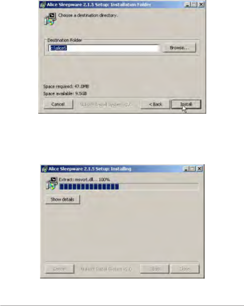
5. Specify the directory where you want the software program to be installed (or use the default
directory shown), and click Install, as shown in Figure 3–3.
Figure 3–3 Installation Directory Screen
A progress bar appears, indicating that the installation is in process, as shown in Figure 3–4.
Figure 3–4 Installation Progress Screen

3–5
Software Installation and Setup
After the installation is complete, the following software shortcut icons are automatically
placed on your desktop for easy access to the software:
Figure 3–5 Sleepware Shortcut Icons
Additionally, if you selected the option to automatically launch the Alice Starter, the Alice
Sleepware starter bar appears at the top of your screen, as shown in Figure 3–6. The Starter
bar is a toolbar that you can use during equipment setup for configuration and during data
acquisitions to view settings or control the optional microphone and camera.
Figure 3–6 Alice Sleepware Starter Bar
Note: If the Alice Sleepware software did not install properly, refer to Chapter 7, Trouble-
shooting for help resolving this problem.
3–6
Alice
®
5 Setup and User’s Guide
3.2 Adding Alice Devices
Through the Alice Sleepware software, you can add Alice 3, 4, or 5 devices. This section de-
scribes how to add Alice 5 devices. For instructions on how to add an Alice 3 or 4 device, refer to
the Alice Sleepware User’s Guide.
3.2.1 Adding an Alice 5 Device
Note: The Alice 5 system does not support the Dynamic Host Configuration Protocol
(DHCP), a protocol for assigning dynamic IP addresses to devices on a network. Yo u
must assign a static IP address to your Alice 5 device.
To add an Alice 5 device, complete the following steps:
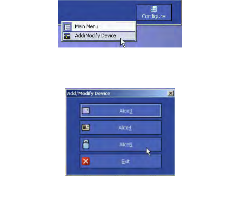
1. Left-click on the Configure button on the Alice Sleepware starter bar, and select Add/Modify
Device as shown in Figure 3–7.
Figure 3–7 Add/Modify Device
2. The Add/Modify Device menu appears, as shown in Figure 3–8. Select Alice 5.
Figure 3–8 Add/Modify Device Menu

3–7
Software Installation and Setup
3. A list of Alice 5 devices that are configured to communicate with your computer appears. If
there are no Alice devices currently configured, the list will be empty, as shown in
Figure 3–9.
Figure 3–9 List of Configured Alice Devices
Click Add to configure an Alice 5 device.

3–8
Alice
®
5 Setup and User’s Guide
4. The Alice 5 Configuration Wizard appears as shown in Figure 3–10. Click Next.
Figure 3–10 Alice 5 Configuration Wizard – Main Screen
5. The Preparing Your PC screen appears, as shown in Figure 3–11.
Figure 3–11 Preparing Your PC Screen
3–9
Software Installation and Setup
Note: If you set up a device on your network with a specific IP address and then later change
the IP address of that same device, you must return to the Add/Modify screens and
reconfigure the device using its new IP address; otherwise, the device will no longer be
found on the network.
If you want to update your settings, click the Edit buttons to the right of the fields and do the
following:
•In the Computer Description field, type in a name for your computer so the Alice
Sleepware software can identify your computer on the network. You should choose a
name that will help you easily identify the computer on the network when you are trying
to set up Alice devices to communicate with that particular computer.
•The Select IP Address for Your PC field will already be filled in if the software has
detected an IP address for your computer. If several IP addresses are included, choose the
address that you want your computer to use to communicate with the Alice 5 device.
If more than one address appears and you are not sure which address is correct, complete
the steps below to find your computer’s IP address:
a. On your computer, go to Start > Control Panel and double-click on Network
Connections.
Note: If you are using Windows 2000 or the Windows Classic theme in Windows XP, you will
need to go to Start>Settings>Control Panel in the above step.
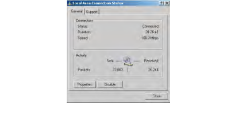
b. Double-click on Local Area Connection (or Wireless Network Connection if you
are on a wireless network) to access the following screen:
Figure 3–12 Local Area Connection Status Screen

3–10
Alice
®
5 Setup and User’s Guide
c. Select the Support tab to view your computer’s IP address, as shown in Figure 3–13.
Figure 3–13 Local Area Connection Status – Support Tab
d. Click Close and then select this address in the Select IP Address for Your PC field
on the Preparing Your PC screen. Click Next.

3–11
Software Installation and Setup
6. The Alice 5 Connection Mode screen appears, as shown in Figure 3–14. Specify whether
your Alice 5 device is connected through its wired or wireless interface, and then click Next.
Figure 3–14 Alice 5 Connection Mode Screen
Attention! On this screen, you are specifying the type of connection from the base station to
the network, not the connection from the computer to the network.
To help determine if your network is wired or wireless, consider the following:
•If your base station is wirelessly connected to the access point, is your access point
connected to the network switch via an ethernet cable? If so, you must choose the wired
network option. Even though your base station is connected to the access point
wirelessly, the access point is then connected to the rest of the network via a wired
connection.
•If all of the devices in your network are wirelessly connected to the access point, choose
the wireless network option (see Figure 2–8 for an example illustrating this setup).
Note: If you are still not sure whether your network is wired or wireless, contact your
network administrator.

3–12
Alice
®
5 Setup and User’s Guide
Note: Refer to Chapter 2 for additional information on wired and wireless network setups.
The Select an Alice 5 device screen appears, as shown in Figure 3–15.
Figure 3–15 Search for Alice 5 devices Screen
7. Select the Alice 5 device that you want to add. The list shows all devices that are available.
Highlight the device and click Next to continue the installation process.
Note: If you are installing a new device or are not sure which device to choose from the list,
find the serial number on the back panel of your Alice 5 base station, and then choose
the device in the list that has that same serial number.
What if My Device Isn’t Listed?
If you cannot find your Alice 5 device in the list provided in Figure 3–15, you will need to place
a check mark by the statement “I did not find the device I want to add, the serial number is not
listed in the above list,” and click Next.

3–13
Software Installation and Setup
The screen shown in Figure 3–16 appears if you are connecting the Alice 5 device through a
wired interface.
Alice 5 - Room 1
192 168 12
Next
Figure 3–16 Alice 5 Device Network Settings Screen – Wired
•Type in a unique name for the Alice 5 base station in the first field. This name will help
you identify the base station on the network.
•In the TCP/IP Address field, type in the unique IP address of the Alice 5 base station you
are adding.
•Click Next and go to Step 9.
3–14
Alice
®
5 Setup and User’s Guide
If you are connecting the Alice 5 device through a wireless interface, when you place a check
mark by the statement “I did not find the device I want to add, the serial number is not listed in
the above list,” in Figure 3–15 and click Next, the screen shown in Figure 3–17 appears.
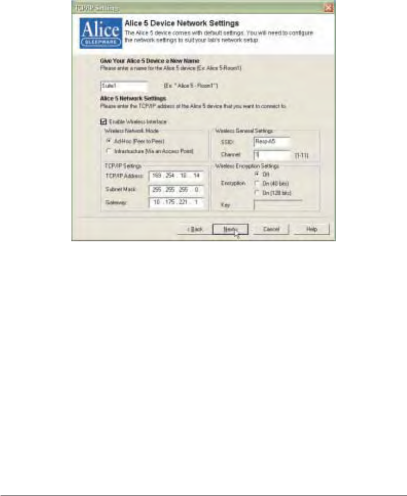
Figure 3–17 Alice 5 Device Network Settings Screen – Wireless
•Type in a unique name for the Alice 5 base station in the first field. This name will help
you identify the base station on the network.
•Check the Enable Wireless Interface box to enable wireless. The wireless setting is
disabled by default when the base station is shipped, so you must check this box in order
to configure the base station’s wireless interface.
•Select Ad-Hoc if you are using a direct, peer-to-peer network, or select Infrastructure
(Via an Access Point) if your network is connected via a wireless access point.
•In the Wireless General Settings, type in the Service Set Identifier (SSID). This is the
unique name shared among all points in a wireless network. The SSID is required if your
Alice 5 base station is connected through a wireless interface. It is case sensitive and
must not exceed 32 characters. Make sure this setting is the same for all points in your
wireless network.

3–15
Software Installation and Setup
•If you selected Ad-Hoc for the wireless network mode, you will need to select the
Channel you are using in the Wireless General Settings. All devices on the network must
share the same channel in order to function correctly. There are 11 possible channels that
you can choose from. Similar to channels on a telephone, you can choose a channel that
does not have much traffic on it to ensure that the wireless connection speed is as fast as
possible. Enter any number from 1-11. If you are not sure what channel to choose,
contact your network administrator.
Note: If you select Infrastructure for the wireless network mode, you will not need to select
a channel. The Channel field will be grayed out.
•In the TCP/IP Address field, type in the unique IP address of the Alice 5 base station you
are adding.
•Select the desired Wireless Encryption setting. You can choose from three levels of
encryption: Off (no encryption), On (64 bits), or On (128 bits).
Off means that there is no security for the data being transferred on the wireless network
between the base station and the computer.
On (64-bit) encryption allows you to enter a 10-character key in the Key field. The
longer or more complicated the key, the more security the encryption may achieve.
On (128-bit) encryption allows you to enter a 26-character key in the Key field, which
provides even greater network security.
•If you’ve enabled encryption, type in the appropriate key (10 characters for 64-bit
encryption or 26 characters for 128-bit encryption). The key can consist of any number
ranging from 0 to 9 and/or any letter ranging from A to F.
•Click Next and go to Step 9.

3–16
Alice
®
5 Setup and User’s Guide
8. If your device appeared in the list of devices on the screen shown in Figure 3–15, after you
highlight the device you want to add and click Next, the screen shown in Figure 3–18
appears. This screen will be different depending on whether you specified that you have a
wired or wireless network on the screen shown in Figure 3–14. If you specified that the Alice
5 is connected through a wired interface, the screen shown in Figure 3–18 appears. If you
specified that the Alice 5 is connected through a wireless interface, the screen shown in Figure
3–19 appears. Follow the instructions for the screen that applies to you.
The screen in Figure 3–18 appears when you are configuring the Alice 5 device’s wired
interface.
Figure 3–18 Alice 5 Device Wired Network Settings
•In the first field, type in a unique name for the Alice 5 base station. This name will help
you identify the base station on the network.

3–17
Software Installation and Setup
•In the Alice 5 Network Settings fields, type in the TCP/IP address, subnet mask, and
gateway information for the Alice 5 device so your computer will be able to fully
communicate with the device on the network.
a. In the TCP/IP Address field, type in the unique TCP/IP address for your Alice 5
device. The Alice 5 device, like your computer, needs to be connected to your
lab or hospital’s computer network in order to exchange data with the computers
on that network.
Note: If you set up your Alice 5 network on its own subnet, you may not need to change the
device’s IP address to a unique address. Each Alice 5 device has its own unique wired
and wireless IP address based on the serial number on the device, so changing the
device’s IP address will not be necessary if you use this type of configuration.
Note:If you do not know the TCP/IP address for your Alice 5 device, contact your network
administrator.
b. Type in the correct Subnet Mask for your Alice 5 device. A subnet mask is like a
filter that is applied to a message’s destination IP address. Its objective is to
determine whether the local network is the destination network. On TCP/IP
networks, subnets consist of all devices whose IP addresses have the same
prefix.
Note: If you do not know what subnet you are on, contact your network administrator.
c. If your Alice 5 device is not on the same subnet as your computer, you need to
enter the correct Gateway address in the Gateway field. Enter the IP address of
your network’s Gateway (such as a router), which is used to allow for contact
between multiple networks. If your network does not have a Gateway, then leave
this field blank.
Note: If you do not know the correct Gateway address, contact your network administrator.

3–18
Alice
®
5 Setup and User’s Guide
The screen in Figure 3–19 appears if you are configuring the Alice 5 device’s wireless
interface.
Figure 3–19 Alice 5 Device Wireless Network Settings
•In the first field, type in a customized name for your Alice 5 device so you and your
colleagues can easily identify the device on your network in the future.
•If you want to connect your device through a wireless interface, check the Enable
Wireless Interface box. The wireless setting is disabled by default when the base
station is shipped, so you must check this box in order to configure the base station’s
wireless interface.
•Select Ad-Hoc if you are using a direct, peer-to-peer network, or select Infrastruc-
ture (Via an Access Point) if your network is connected via a wireless access point.
•The Alice 5 device comes with default TCP/IP settings. You should change these
settings to suit your network.
a. In the TCP/IP Address field, type in the unique TCP/IP address for your Alice 5
device. The Alice 5 device, like your computer, needs to be connected to your
lab or hospital’s computer network in order to exchange data with the computers
on that network.

3–19
Software Installation and Setup
Note: If you set up your Alice 5 network on its own subnet, you may not need to change the
device’s IP address to a unique address. Each Alice 5 device has its own unique wired
and wireless IP address based on the serial number on the device, so changing the
device’s IP address will not be necessary if you use this type of configuration.
Note:If you do not know the TCP/IP address for your Alice 5 device, contact your network
administrator.
b. Type in the correct Subnet Mask for your Alice 5 device. A subnet mask is like a
filter that is applied to a message’s destination IP address. Its objective is to
determine whether the local network is the destination network. On TCP/IP
networks, subnets consist of all devices whose IP addresses have the same
prefix.
Note: If you do not know what subnet you are on, contact your network administrator.
c. If your Alice 5 device is not on the same subnet as your computer, you need to
enter the correct Gateway address in the Gateway field. Enter the IP address of
your network’s Gateway (such as a router), which is used to allow for contact
between multiple networks. If your network does not have a Gateway, then leave
this field blank.
Note: If you do not know the correct Gateway address, contact your network administrator.
•If you are using the device on a wireless network, set your Wireless Encryption
settings and general settings.
a. The Service Set Identifier (SSID) is the unique name shared among all points in
a wireless network. The SSID is required if your Alice 5 base station is con-
nected through a wireless interface. It is case sensitive and must not exceed 32
characters. Make sure this setting is the same for all points in your wireless
network.
Note: Contact your network administrator if you do not know the correct SSID.
b. If you selected Ad-Hoc for the wireless network mode, you will need to select
the Channel you are using in the Wireless General Settings. All devices on the
network must share the same channel in order to function correctly. There are 11
possible channels that you can choose from. Similar to channels on a telephone,
you can choose a channel that does not have much traffic on it to ensure that the
wireless connection speed is as fast as possible. Enter any number from 1-11. If
you are not sure what channel to choose, contact your network administrator.

3–20
Alice
®
5 Setup and User’s Guide
Note: If you select Infrastructure for the wireless network mode, you will not need to select
a channel. The Channel field will be grayed out.
c. You can choose from three levels of encryption: Off (no encryption), On (64
bits), or On (128 bits).
Off means that there is no security for the data being transferred on the wireless
network between the base station and the computer.
On (64-bit) encryption allows you to enter a 10-character key in the Key field.
The longer or more complicated the key, the more security the encryption may
achieve.
On (128-bit) encryption allows you to enter a 26-character key in the Key field,
which provides even greater network security.
d. If you’ve enabled encryption, type in the appropriate key (10 characters for 64-
bit encryption or 26 characters for 128-bit encryption). The key can consist of
any number ranging from 0 to 9 and/or any letter ranging from A to F.
Note: All points in your wireless network must use the same key to utilize encryption.
•Click Next once you are finished updating your settings.

3–21
Software Installation and Setup
The Acquisition Data Recipient screen appears, as shown in Figure 3–20.
Figure 3–20 Acquisition Data Recipient Screen
9. Select where you want to store your data, and then click Next.
•Select Option 1 to store the data on your computer.
•Select Option 2 if you do not want the data stored on this computer. The data will be
stored on the base station, unless you run this wizard again on a different computer and
designate that computer as the data recipient.
Note: If you want data from the Alice 5 device to be sent to another computer, you must run
this Wizard on another computer in the network and choose Option 1 for that com-
puter.

3–22
Alice
®
5 Setup and User’s Guide
10. If the wireless interface is disabled (because you did not check the Enable Wireless Interface
box in Figure 3–19), the Wireless Interface Disabled screen appears, as shown in Figure 3–21.
Figure 3–21 Wireless Interface Disabled Screen
This screen indicates that the wireless interface on the Alice 5 device is currently disabled. To
enable the wireless interface, you will need to edit the device properties by clicking on the
Edit button in the Alice 5 Add/Modify Device dialog box. See the Alice Sleepware User’s
Guide for more information.
Note: This screen will not appear if the wireless interface has been enabled.
11. Click Finish to complete the process of adding a device.
12. The Alice 5 Device List screen appears, displaying the devices that are configured on your
computer. The device you just added should appear in the list, as shown in Figure 3–22.

3–23
Software Installation and Setup
Figure 3–22 Alice 5 Device List Screen
Additionally, once the device is successfully added, a Room button appears in your Alice
Sleepware starter bar, indicating the device’s status, as shown in Figure 3–23.
Figure 3–23 Alice 5 Device Status Indicator
Note: You can also edit devices through the Alice 5 Configuration Wizard and delete or view
device properties through the Add/Modify Device screens. For more information, refer
to the Alice Sleepware User’s Guide.

3–24
Alice
®
5 Setup and User’s Guide

4–1
Data Acquisition
CHAPTER
4
Running Data Acquisitions
This chapter describes how to set up the patient so the data you need will be properly recorded,
and instructs you on how to start and stop an acquisition. See Chapter 5 for information on the
channels that can be recorded, and see the Alice Sleepware User’s Guide for detailed instructions
on using the software.
4.1 Overview
The Alice Sleepware software allows you to view and score data acquisitions while an acquisi-
tion is in progress. It can also download and organize the data after an acquisition has been
recorded. Data acquisitions are sorted by patient identity (e.g., name and ID number), thus
providing tracking of patient recording history. Multiple acquisitions performed on one patient
may be easily located within the database.
Using Alice Sleepware, you can view raw waveform data in various time and montage formats. A
detailed view of the recording can be seen by scrolling through the data. You may select the
channels displayed on the screen and the color of the raw data, and print any raw data screen or
groups of screens. Global patterns or trends for the recording may be viewed via the use of
1-hour or 10-hour summary screens. You can view video of the patient while they sleep, and you
can save streaming video or snapshots along with the sleep data.
Alice Sleepware automatically detects physiologic events such as apnea, hypopnea, snoring,
periodic limb movements, heart rate, arrhythmia, pH, and arousal. Events may also be distin-
guished according to their context (e.g., an apnea with an associated heart rate or saturation
decrease). Alice Sleepware also recognizes a number of neurological events for staging adult
sleep and cardio-respiratory patterns or activity for staging infant sleep.

4–2
Alice
®
5 Setup and User’s Guide
You can validate detected events, add additional events, remove events, or change the event type,
duration, or position of a detected event. Based upon the validation, Alice Sleepware computes
relevant statistical values. The values may be displayed in a report format that is user-
configurable. You can print the reports immediately or display them for on-screen review. You
can also design custom report formats using the custom report feature.
4.2 Patient Setup
Note:Only trained personnel should use the Alice 5 system.
Once you have installed your Alice 5 equipment and the Alice Sleepware software, you are ready
to begin collecting data. You will need to attach the appropriate patient sensors from the headbox
to the patient to acquire the data you need.
Note: The Alice system supports the placement of EEG sensors using 10-20 Electrode
Placement standards only. The 10-20 Electrode Placement standards were developed
to provide consistent application of EEG sensors for recording brain wave data. This
system is based on measurements from four standard points on the head: the nasion,
the inion, and the left and right periauricular points. You should mark and prepare
each position before actually applying the electrodes.
The age of the patient determines the acquisition type and the type of data collected. There are
two acquisition types:
•Infant – The patient age for this acquisition type is less than six months. During record-
ing of an Infant acquisition, the base station scores sleep using cardio-respiratory stability
and actimetry. Likewise, after recording, Alice Sleepware scores sleep using cardio-
respiratory stability and actimetry.
•Adult – The patient age for this acquisition type is six months or older. During recording
of an Adult acquisition, the base station doesn’t score sleep. After the recording, Alice
Sleepware scores sleep using EEG and EMG data (by default).
You can collect EEG data for Infant acquisition types, but Alice Sleepware does not use it to
score Pneumo sleep stages because EEG patterns are not fully developed until after humans reach
the age of six months.
The acquisition type is different from the sleep scoring method. After the recording, you can
determine (using Alice Sleepware) whether sleep is scored using Neuro or Pneumo sleep stages.
By default, the Alice Sleepware software associates adult acquisitions with Neuro sleep stages
and infant acquisitions with Pneumo sleep stages.
See Chapter 5, Understanding Channels, for information about the channels that the Alice 5
equipment supports. See Figures 1–4 and 1–6 for the locations to attach devices to the Alice 5
equipment. You can attach sensors to the patient in any order.

4–3
Data Acquisition
Left Frontal Polar EEG
Right Central EEG
Left Temporal EEG
Right Parietal EEG
Left Parietal EEG
Right Frontal Polar EEG
Right Frontal EEG
Left Anterior Temporal EEG
Site Description
Left Central EEG
Right Anterior Temporal EEG
Left Frontal EEG
Fp1
Fp2
F3
F4
F7
F8
C3*
C4*
P3
P4
T3
T4 Right Temporal EEG
T5 Left Posterior Temporal EEG
T6 Right Posterior Temporal EEG
A2* Right Reference (right ear)
A1* Left Reference (left ear)
Isoground
Ground
O1* Left Occipital EEG
O2* Right Occipital EEG
* Recommended by Rechtschaffen and Kales
Fz Frontal Zero EEG (mid-line)
Cz Central Zero EEG (mid-line)
Pz Parietal Zero EEG (mid-line)
Note: If you have sensors from auxiliary devices such a pH machines, oximeters, apnea
monitors, etc., follow the manufacturer’s instructions for attaching the sensors to the
patient.
4.2.1 Attaching EEG Electrodes
You should attach the EEG electrodes specified by your facility’s protocol and based on the
configuration you choose. Table 4–1 lists the typical EEG sites from which data is collected
during a sleep study.
Table 4–1 Typical EEG Sites for Collecting Data

4–4
Alice
®
5 Setup and User’s Guide
Complete the following steps to attach the EEG sensors to the patient:
1. Following the manufacturer’s recommendations, attach the EEG leads to the patient’s scalp
according to your facility’s procedures.
Note: Respironics recommends that you use standard gold-cup electrodes for all EEG
connections.
2. Decide whether you want to set the sensors up contralaterally or ipsilaterally. In the U.S.,
adult studies use a contralateral setup, while infant studies always use an ipsilateral setup. In
Europe, an ipsilateral setup is used.
•Ipsilateral setups: Plug the A1 reference electrode lead (on the left side of the patient’s
head) into the A1 input on the left side of the headbox, and plug the A2 reference
electrode lead (on the right side of the patient’s head) into the A2 input on the right side
of the headbox.
•Contralateral setups: Plug the A1 reference electrode lead (on the left side of the patient’s
head) into the A2 input on the right side of the headbox, and plug the A2 reference
electrode lead (on the right side of the patient’s head) into the A1 input on the right side
of the headbox.
3. Plug the main EEG electrode leads into the appropriate connectors on the Alice 5 headbox.
4. Place the Isoground electrode on the center of the patient’s forehead, and plug the lead into
the Isoground input on the Alice 5 headbox.
Caution: If you use an EEG Isoground, do not use the left ECG lead.
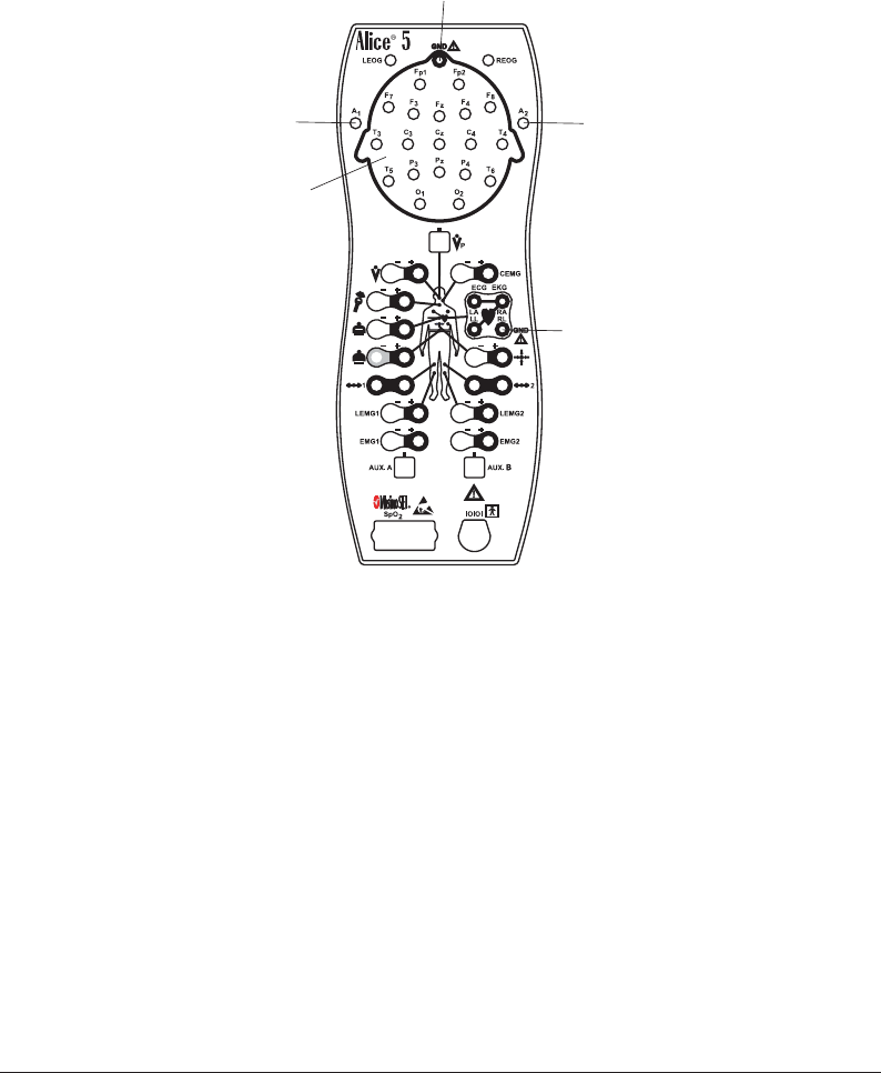
4–5
Data Acquisition
Figure 4–1 shows the locations of the EEG inputs on the Alice 5 headbox.
These are the inputs
for the main EEG
electrodes
(see Table 4–1
for details)
A2 Reference Electrode
Isoground
attaches here
A1 Reference Electrode
Isoground
attaches here
Figure 4–1 EEG Inputs on the Alice 5 Headbox

4–6
Alice
®
5 Setup and User’s Guide
4.2.2 Attaching ECG Electrodes
The Alice 5 system supports a single lead ECG or a 6-lead ECG. The single lead ECG uses two
or three wires from the headbox (the right leg is optional, depending on whether an EEG
Isoground is also used with the patient). The 6-lead ECG uses three or four wires from the
headbox (right leg optional), and Alice calculates the six channels by cross-referencing the
signals.
Table 4–2 lists the wire colors.
Table 4–2 ECG Standard Protocols
Lead II
Lead II
Type Lead Number
Lead I
RA (right arm) = White
LA (left arm) = Black
RL (right leg) = Green
Note: Do not connect the RL lead if you
are using an EEG Isoground.
Single Lead ECG
6-Lead ECG
Colors
North American Headbox (according to AAMI, AHA-Code, or US Code)
RA (right arm) = White
LA (left arm) = Black
RL (right leg) = Green
Note: Do not connect the RL lead if you
are using an EEG Isoground.
RA (right arm) = White
LL (left leg) = Red
International Headbox (according to IEC-Code or EU-Code)
Lead II RA (right arm) = Red
LA (left arm) = Yellow
RL (right leg) = Black
Note: Do not connect the RL lead if you
are using an EEG Isoground.
Single Lead ECG
Lead II
Lead I
6-Lead ECG RA (right arm) = Red
LA (left arm) = Yellow
RL (right leg) = Black
Note: Do not connect the RL lead if you
are using an EEG Isoground.
RA (right arm) = Red
LL (left leg) = Green
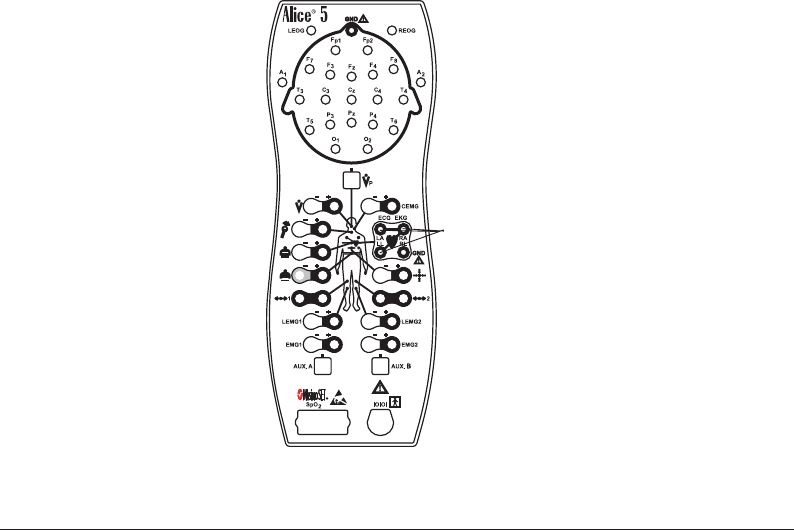
4–7
Data Acquisition
Complete the following steps to attach the ECG electrodes to the patient:
1. Refer to Table 4–2 and choose the standard protocol for your area.
2. Snap the ECG leads onto adhesive electrode patches.
3. Attach the patch for the right arm to the top right side of the patient’s chest, approximately
one inch (2.54 cm) below the collarbone.
4. Attach the patch for the left arm to the top left side of the patient’s chest, approximately one
inch (2.54 cm) below the collarbone. The green lead is for the ECG Ground. For a single-lead
ECG, you are finished with this procedure. If you are doing a 6-lead ECG, proceed to Step 5.
5. Attach the patch for the right leg on the patient’s right side at the lowest rib. Do not place the
patch forward toward the patient’s stomach; it should be placed directly on the patient’s side.
6. Attach the patch for the left leg on the patient’s left side at the lowest rib. Do not place the
patch forward toward the patient’s stomach; it should be placed directly on the patient’s side.
Caution: If you use an EEG Isoground, do not use the left ECG lead.
7. Plug the other ends of the ECG leads into the appropriate locations on the Alice 5 headbox,
shown in Figure 4–2.
ECG/EKG
Figure 4–2 ECG Inputs on the Alice 5 Headbox
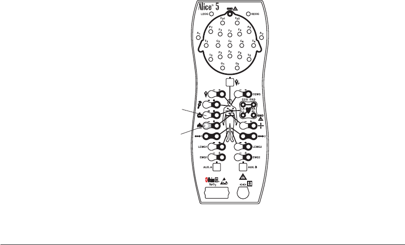
4–8
Alice
®
5 Setup and User’s Guide
4.2.3 Attaching Chest and Abdomen Effort Sensors
Complete the following steps to attach the chest and abdomen sensors to the patient:
Note: If you want to use another method for monitoring an infant’s breathing effort (for
example, an apnea monitor), follow the manufacturer’s guidelines for attaching the
sensors.
1. Place the chest effort belt around the patient’s chest so that the Velcro® is in the center of the
chest and the black fasteners are evenly aligned with the patient’s nipples. The connector
should hang straight in front of the patient.
2. Plug the lead into the Alice 5 headbox.
3. Place the abdominal belt around the patient’s stomach so that the vinyl part of the sensor is
directly over the navel and does not rotate around the torso. The fasteners on the belt should
be aligned with the patient’s hips. The connector should hang straight in front of the patient.
Warning: For infants, do not tighten the belt to the point of impeding the infant’s breathing.
Also, check the tension of the effort belts before and after feedings. As the infant
eats, his or her belly may expand and the belts may become uncomfortably tight.
4. Plug the lead into the Alice 5 headbox.
Figure 4–3 shows the chest and abdomen sensor locations on the headbox.
Abdominal
Effort Belt
Chest
Effort Belt
Figure 4–3 Chest and Abdomen Sensor Inputs on the Alice 5 Headbox
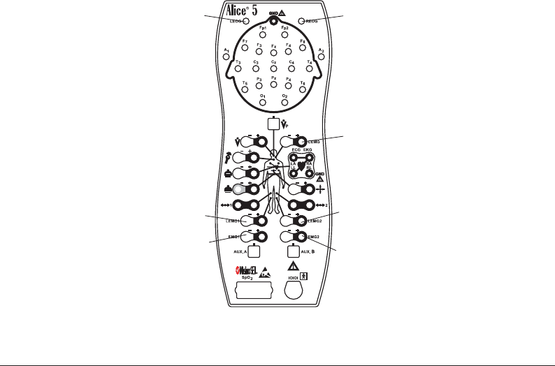
4–9
Data Acquisition
4.2.4 Attaching the EOG and EMG Electrodes
4.2.4.1 EOG Electrodes
Complete the following steps to attach the EOG electrodes to the patient.
1. Attach the EOG leads to the patient.
2. Plug the leads into the appropriate inputs on the headbox, as shown in Figure 4–4.
4.2.4.2 Leg EMG Electrodes
1. Place the Leg EMG leads on the patient according to your facility’s specifications. There
should be two leads on each limb to be monitored. Using only one lead per limb can result in
a faulty signal.
2. Plug the pair of leads for each limb into the appropriate inputs on the headbox, as shown in
Figure 4–4.
4.2.4.3 Chin EMG Electrodes
1. Attach the Chin EMG to the patient.
2. Plug the lead into the Chin EMG input on the headbox, as shown in Figure 4–4.
Spare EMG Spare EMG
Leg EMG Leg EMG
Left EOG
attaches here Right EOG
attaches here
Chin EMG
attaches here
Figure 4–4 EOG and EMG Inputs on the Alice 5 Headbox
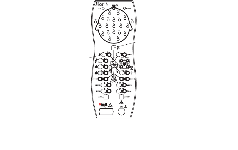
4–10
Alice
®
5 Setup and User’s Guide
4.2.5 Attaching the Airflow Sensor
Complete the following steps to attach the airflow sensor to the patient:
1. Make sure you have the proper size sensor for your patient; both adult and infant sizes are
available.
2. For the pressure-based sensor, position the nasal pressure cannula above the upper lip with the
cannula protruding slightly into the nostrils. Trim if necessary per the manufacturer’s guide-
lines.
3. For the thermistor sensor, position the sensor so that the flexible tabs fit under the nostrils.
Pinch the tabs back 90° so that they are comfortable, yet not touching the skin and not
protruding into the nares. The tabs bend out, away from the patient’s face. The logo on the
thermistor sensor is readable to the technician if the sensor is applied properly.
Caution: Use caution when placing the sensor on the patient. To avoid cuts or irritation to
the skin, do not place the sensor too close to the nares.
4. Drape the leads over the patient’s ears and connect the input to the Alice 5 headbox.
5. If desired, tape the leads to the patient’s cheeks to help hold the sensor in place.
Figure 4–5 shows the location of the airflow sensor inputs on the headbox.
Thermistor
Flow Sensor
Pressure-Based
Flow Sensor
Figure 4–5 Airflow Sensor Inputs on the Alice 5 Headbox

4–11
Data Acquisition
Note: You may have additional sensors from auxiliary devices such as pH machines,
oximeters, apnea monitors, etc. These can be connected to the auxiliary input ports on
the back of the Alice 5 base station. See Chapter 1 for more information about the
auxiliary input ports. Follow the manufacturer’s instructions for attaching these
sensors to the patient.
4.3 Starting an Acquisition
Before you start running an acquisition, you should review your cable connections and check
your equipment as specified below.
4.3.1 Check Your Cable Connections
Review your cable connections as described below before starting an acquisition.
1. Check the sensor connections.
Verify that each sensor is plugged into the appropriate connector on the Alice 5 headbox.
Refer to Figure 1–6 and Section 4.2, Patient Setup, for more information.
Verify that the Patient Cable is connected properly from the headbox to the base station. See
Figures 2–10 and 2–11.
2. Check the auxiliary device connections (if applicable).
Verify that each auxiliary device is connected to the base station using the auxiliary input
specified during the channel setup. See Chapter 5, Understanding Channels, for more
information.
3. Check the base station connections.
If you are using a wired network connection, make sure the ethernet cable is inserted into the
ethernet port on the back of the base station, as described in Chapter 2, Alice 5 Hardware
Setup. Use one of the following cables:
•CAT-5 Crossover Cable – Connects the base station directly to the computer running
Alice Sleepware software
•CAT-5 Patch Cable – Connects the base station to a switch or ethernet connector

4–12
Alice
®
5 Setup and User’s Guide
4.3.2 Check Your Equipment Performance
You should verify that the Alice 5 equipment is operating properly before starting an acquisition.
Check impedance and calibration by completing the following procedures.
4.3.2.1 Check Impedance Using the Alice Sleepware
The Alice 5 allows you to view impedance values at anytime during your study without impact-
ing the physiological data that is being recorded. You won’t lose any physiological signals when
viewing impedance. To check impedance, complete the following steps:
1. Set up the appropriate sensors.
Note: The impedance feature works for the EEG, EOG, ECG, and EMG channels.
2. Check all of the required cable connections as described in Section 4.3.1.
3. Start an acquisition as described in Section 4.3.3.
The Alice equipment begins capturing data from the sensors.
4. Click on the Imped. button while viewing the acquisition through Sleepware.
The Sleepware software continuously displays the impedance value for each channel. The
channel tabs to the left of each channel displayed indicate the impedance value by color:
•A red tab indicates a high impedance value (a poor connection).
•A dark green tab indicates a moderate impedance value (a fair connection).
•A light green tab indicates a low impedance value (a good connection).
Note: The channel label tab always indicates the impedance status, regardless of whether or
not you have pressed the Imped button. The actual impedance value is displayed when
you press Imped.
Note: The threshold values for impedance are user-configurable.
Note: The impedance values are also available for review after the acquisition is recorded.

4–13
Data Acquisition
5. Use the information in Table 4–3 to determine whether further action is needed.
Table 4–3 Electrode Impedance
Replace the electrode using your lab's procedures.
Consider changing the electrode using your lab's
procedures.
Impedance Recommended Action
None. The sensor has a good connection.
> 10 Ohms
Between 5k Ohms
and 10k Ohms
< 5k Ohms
4.3.2.2 Check Calibration
1. Set up the sensors as described in Section 4.2.
2. Connect all of the required cables and check the connections as described in Section 4.3.1.
3. Start an acquisition as described in Section 4.3.3.
The Alice equipment begins capturing data.
4. In the On-line View window that appears, click on the Calib. button in the toolbar to generate
a 100 mV signal on the ECG, EEG, EMG, and EOG channels. The Alice Sleepware displays
the calibration signal in the waveform.
5. Let the process run for at least 30 seconds, then click the button again.

4–14
Alice
®
5 Setup and User’s Guide
Check Bio-Calibration
1. Set up the sensors as described in Section 4.2.
2. Connect all of the required cables and check the connections as described in Section 4.3.1.
3. Start an acquisition, as described in Section 4.3.3.
The Alice 5 equipment begins capturing data.
4. Ask the patient to lie on his or her back with arms along the body, eyes closed, and breathing
regularly and gently. Test the sensors by asking the patient to follow the instructions in Table
4–4 below.
Table 4–4 Checking the Sensors
Without moving their head, have the patient close the eyelids and
slowly move the eyes right and left repeatedly for ten seconds.
Next, have the patient close the eyelids and slowly move the
eyes up and down for ten seconds.
Have the patient relax the jaw for five seconds, then contract the
jaw by biting for three seconds, then relax again. Repeat this
three or four times.
Sensor Action
Have the patient breathe at a steady rhythm for 15 seconds
while making a snoring sound during inspiration, or have the
patient count from 1 to 10.
EOG
Chin EMG
Microphone
Abdominal and chest
effort, thermistor or
pressure cannula
airflow.
Have the patient breathe through the nose at a steady rhythm for
five seconds, then repeat by breathing through the mouth.
Next, have the patient hold their breath for five seconds
and then release.
Leg EMG Have the patient contract a calf muscle for one second, then
relax for one second; repeat five times. Repeat for the other calf.
Have the patient point their toes, bend forward, hover, and
repeat.
EEGs Have the patient open the eyelids, relax, and look straight
ahead for ten seconds. Then, have the patient close the eyelids,
relax, and keep eyes facing straight ahead for ten seconds.
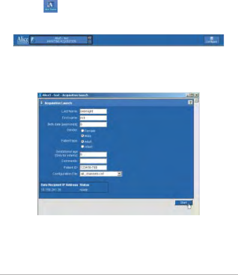
4–15
Data Acquisition
4.3.3 Starting an Acquisition
To start the data acquisition, complete the following steps:
1. Configure the Communication Settings for connection to the Alice 5 device you are using (see
the Alice Sleepware User’s Guide for instructions on configuration).
2. If the Alice Starter module is not already running on your computer, double-click on the Alice
Starter icon ( ) .
The name of your device appears in the Starter bar at the top of the computer screen, along
with the words “Awaiting Acquisition” as shown in Figure 4–6.
Figure 4–6 Starter Bar and Device Awaiting Acquisition
3. Click on the name of the device.
The Acquisition Launch screen appears as shown in Figure 4–7.
Figure 4–7 Acquisition Launch Screen
4. Click on Start to begin the acquisition.
The On-Line View screen appears, displaying all of the acquisition data. Green on the Alice
Starter bar and the On-Line View screen indicates that the connection is successful and the
acquisition is recording.

4–16
Alice
®
5 Setup and User’s Guide
Note: It is recommended that you start an acquisition through the Sleepware software.
However, if this is not available, you can press the Record Start/Stop button on the
base station. The Record LED is green while the base station records data.
Refer to the Alice Sleepware User’s Guide for additional information on starting acquisitions.
4.2.4 Stopping an Acquisition
To stop an acquisition, click the Stop button on the On-Line View screen in Sleepware.
Note: It is recommended that you stop an acquisition through the Sleepware software.
However, if this is not available, you can press the Record Start/Stop button on the
base station twice to stop the acquisition. The Record LED turns off when the base
station stops recording data.

5–1
Understanding Channels
CHAPTER
5
Understanding Channels
Channels refer to the different types of data collected by the auxiliary devices and sensors
connected to the patient. The set of channels used in any particular sleep study is referred to as a
configuration.
You can configure the channels based on the type of information you need to collect for the
study. Once you set up the patient and have the data coming in from the channels you configured,
you can use the Alice Sleepware to filter channels, create a montage, etc. Refer to the Alice
Sleepware User’s Guide for information on how to build configurations and create montages.
There are four types of Alice 5 channels:
•Headbox channels
•Base Station auxiliary channels
•Therapy device channels
•Derived channels
These are discussed in the sections that follow.
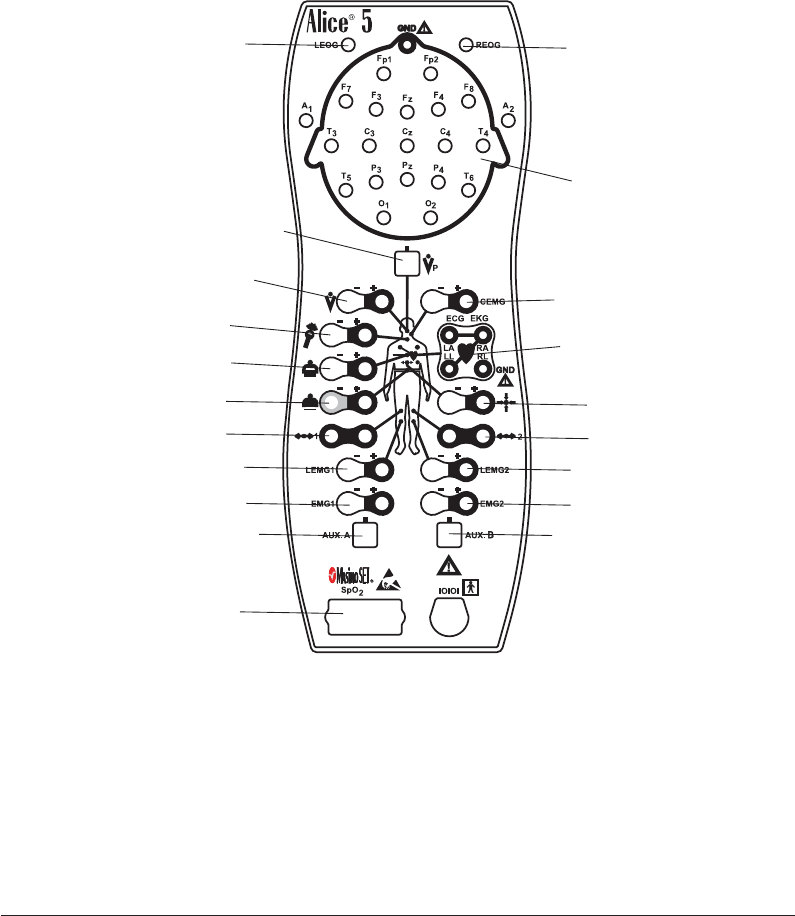
5–2
Alice
®
5 Setup and User’s Guide
5.1 Headbox Channels
The channels available on the Alice 5 headbox are shown in Figure 5–1.
Pleth/Pulse Rate/SpO2
channel (Oximeter)
Auxiliary Input Auxiliary Input
Spare EMG channel Spare EMG channel
Leg EMG channel Leg EMG channel
Actimeter channel Actimeter channel
Abdominal Effort channel Body Position channel
Chest Effort channel
Snore channel
Thermistor-Based
Airflow channel
Pressure-Based
Airflow channel
Chin EMG channel
ECG channels
EEG channels
EOG channel EOG channel
Figure 5–1 Headbox Channels

5–3
Understanding Channels
Table 5–1 provides the following information about each of the headbox channels:
•The Channel column lists the name of the channel.
•The Channel Quantity column tells how many inputs are available on the Alice 5
headbox for each channel.
•The Sample Size (in bits) column specifies the bit resolution for the channel being
acquired.
• The Recorded Frequency (in Hertz) column tells you how often the data is recorded per
second. Many channels have several frequency rates available. You can choose how often
you want these channels to record through the Alice Sleepware.
•The Range column specifies the range of values to which the data corresponds.
•The Units column specifies the unit of measure for each channel.
Table 5–1 Headbox Channels
2
Channel Channel
Quantity
Actimeter
Airflow
(pressure-based)
Sample
Size (bits)
Recorded
Frequency (Hz)
Range Units
81
1 8, 10, 12, 16 10, 100, 200 ±68.3 mV
Airflow
(thermistor-based) 112, 16 10, 100, 200 ±68.3 mV
Body Position 181 N/A N/A
ECG 2 (physical)
6 (computed - 2
phy./4 leads)
8, 10, 12, 16 200, 500 ±6.6 mV
EEG 19 10, 12, 16 100, 200 ±.33 µV
Effort, abdominal 1 12, 16 10, 100, 200 N/A N/A
Effort, chest 1 12, 16 10, 100, 200 N/A N/A
EMG, chin 1 10, 12, 16 100, 200 ±3.3 mV
EMG, leg 2 10, 12, 16 100, 200 ±3.3 mV
EMG, spare 2 8, 10, 12, 16 200 ±3.3 mV
EOG 2 8, 10, 12, 16 100, 200 ±3.3 mV
Snore 1 8, 10, 12, 16 200 ±18 mV
Pleth
(Masimo Oximeter) 116 100, 200 N/A N/A
Pulse Rate
(Masimo Oximeter) 1 8, 10, 12, 16 1 25 to 240 BPM
SpO2
(Masimo Oximeter) 110
1, 10, 100, 200 70 to 100 %
N/A N/A
Auxiliary Channels 212 10, 100, 200 ±1.65 V

5–4
Alice
®
5 Setup and User’s Guide
Each physical input channel is described in more detail below:
1Actimetry
The actimetry channel type is used to sense motion signals from the patient. Actimetry is one
of the channels by which the Alice Sleepware scores sleep in infant configurations, so it is a
necessary channel in an infant configuration. The channel may also be used in adult configu-
rations, but is usually not as important because EEG is available for scoring sleep.
With Alice 5, you can set customized parameters for this channel using the Alice Sleepware.
Please refer to Table 5–1 for a detailed description of actimetry channel features. After
customizing your configuration, you can use the Label function to enter a text description for
your configuration of up to eight characters.
2Airflow (Pressure-based or Thermistor-based)
The airflow channels are used to display data from a device that measures the patient’s
airflow. You can use the airflow sensor channel type by connecting a Respironics thermistor
or pressure cannula airflow sensor to the headbox.
Note: If you label this channel “Flow,” the Alice Sleepware can scan the data and automati-
cally score apneas and hypopneas. Refer to the Alice Sleepware User’s Guide for more
information.
You can customize parameters for this channel. Refer to Table 5–1 for a detailed description
of airflow channel features. After customizing your configuration, you can use the Label
function to enter a text description for your configuration of up to eight characters.
Note: Therapy device or auxiliary airflow channels are also available when you connect a
Respironics therapy device to the COM 1 serial port on the back of the base station, or
when you connect a third-party airflow sensor to an auxiliary input on the base
station. See Sections 5.2 and 5.3 for more information.

5–5
Understanding Channels
3Body Position
The body position channel tells you the orientation of the patient’s body in the bed. The body
position sensor can report five possible positions:
•Supine (patient is sleeping on their back)
•Prone (patient is sleeping on their stomach, facedown)
•Right side
•Left side
•Upright
You can select customized parameters for this channel. Please refer to Table 5–1 for a
detailed description of Body Position channel features. After customizing your configuration,
you can use the Label function to enter a text description for your configuration of up to eight
characters.
4ECG
The ECG channel type is used to display data from an electrocardiogram channel. To use this
channel, connect an ECG electrode to the ECG inputs on the headbox as needed. See Chapter
4 for additional information.
You can set customized parameters for this channel. Please refer to Table 5–1 for a detailed
description of ECG channel features. After customizing your configuration, you can use the
Label function to enter a text description for your configuration of up to eight characters.
Note: An auxiliary ECG channel is also available when connecting an ECG monitoring
device to one of the auxiliary inputs on the back of the base station. See Section 5.2 for
more information.
Note: The RR channel is used to display R-wave to R-wave data that Alice computes from the
ECG input signal. See Section 5.4 for more information about the RR channel.

5–6
Alice
®
5 Setup and User’s Guide
5EEG
The EEG channel type is used to display data from an electroencephalogram channel.
Note: The Alice system supports the placement of EEG sensors using 10-20 Electrode
Placement Standards only. For more information, see Chapter 4.
You can select customized parameters for this channel. Please refer to Table 5–1 for a detailed
description of EEG channel features. After customizing your configuration, you can use the
Label function to enter a text description for your configuration of up to eight characters.
Selecting the Reference Specification:
In the Alice Sleepware, you can specify whether you want to set the sensors up contralaterally
or ipsilaterally. In the U.S., adult studies use a contralateral setup, while infant studies always
use an ipsilateral setup. In Europe, an ipsilateral setup is used.
•Ipsilateral setups: Plug the A1 reference electrode lead (on the left side of the patient’s
head) into the A1 input on the left side of the headbox, and plug the A2 reference
electrode lead (on the right side of the patient’s head) into the A2 input on the right side
of the headbox. In Sleepware, for configurations referenced ipsilaterally (on the same
side of the head), you would specify A1 for the left channel’s reference electrode and A2
for the right channel’s reference electrode.
•Contralateral setups: Plug the A1 reference electrode lead (on the left side of the
patient’s head) into the A1 input on the right side of the headbox, and plug the A2
reference electrode lead (on the right side of the patient’s head) into the A2 input on the
right side of the headbox. In Sleepware, for configurations referenced contralaterally
(across the head), you would specify A1 for the right channel’s reference electrode and
A2 for the left channel’s reference electrode, thus producing channels like C3A2, O1A2,
etc.
Note: The Alice 5 base station defaults to a contralateral configuration.

5–7
Understanding Channels
6Effort – Abdominal and Chest (Respiration)
The respiration channel type is used to display chest and abdomen effort signals and trans-
thoracic impedance signals.
The Alice system provides two effort channels: thoracic effort and abdominal effort. Addi-
tional effort channels must be input using the auxiliary inputs. The Alice Sleepware scans all
effort channels to detect apneas on the airflow channel. The Alice system also allows you to
monitor trans-thoracic impedance, which can be acquired from an infant monitor or other
auxiliary device.
You can use the effort channel type by connecting the chest and abdominal effort belts to the
inputs on the headbox.
Note: Abdominal and chest effort auxiliary channels are also available if you connect a
third-party respiration measuring device to an auxiliary input on the rear of the base
station. See Section 5.2 for more information.
You can set customized parameters for this channel. After customizing your configuration,
you can use the Label function to enter a text description for your configuration of up to eight
characters.
7EMG (Chin and Spare)
The EMG channel type is typically used to display data for the chin EMG and the two spare
EMGs, but it can be used for any electromyogram channel.
Note: The Leg EMG channel type is described in #8, below.
You can select customized parameters for this channel. Please refer to Table 5–1 for a
detailed description of EMG channel features. After customizing your configuration, you can
use the Label function to enter a text description for your configuration of up to eight charac-
ters.
8EMG (Leg)
The leg EMG channel type is used to display data from limb movement detection channels.
If you use both leg EMG inputs, note that the single leg EMG channel combines the data from
both inputs.
You can select customized parameters for this channel. Please refer to Table 5–1 for a detailed
description of leg EMG channel features. After customizing your configuration, you can use
the Label function to enter a text description for your configuration of up to eight characters.

5–8
Alice
®
5 Setup and User’s Guide
9EOG
The EOG channel type is used to display data from an electrooculogram channel. You can
select customized parameters for this channel. After customizing your configuration, you
can use the Label function to enter a text description for your configuration of up to eight
characters.
10 Snore
The snore channel type is used to display data from a tracheal vibration sensor. This is
not a sound sensor. A typical use of this channel in sleep studies is to measure snoring.
The snore input is not calibrated.
You can select customized parameters for this channel. Please refer to Table 5–1 for a
detailed description of snore channel features. After customizing your configuration, you
can use the Label function to enter a text description for your configuration of up to eight
characters.
11 Pleth
The pleth channel type is used to display (as a waveform) changes in arterial blood flow
detected by the Masimo sensor.
You can select customized parameters for this channel. Please refer to Table 5–1 for a
detailed description of pulse channel features. After customizing your configuration, you
can use the Label function to enter a text description for your configuration of up to eight
characters.
12 Pulse Rate
The pulse rate channel type is used to display numerical data from the Masimo pulse
oximeter. To use the pulse rate channel type, connect a finger probe through a patient
interface cable to the oximeter connection on the headbox.
You can set customized parameters for this channel. Please refer to Table 5–1 for a
detailed description of pulse rate channel features. After customizing your configuration,
you can use the Label function to enter a text description for your configuration of up to
eight characters.

5–9
Understanding Channels
13 SpO2
The SpO2 channel type is used to display blood oxygen saturation data from the internal
oximeter or from an external device.
You can use the SpO2 channel type by connecting the Masimo oximeter sensor to the
oximeter connection on the headbox (see Figure 1–6).
Note: An SpO2 auxiliary channel is also available when you connect a third-party oximeter
to an auxiliary input on the back of the base station. See Section 5.2 for more informa-
tion.
You can set customized parameters for this channel. After customizing your configura-
tion, you can use the Label function to enter a text description for your configuration of
up to eight characters.
Conversion:
You can configure parameters for this channel type so that the input signal is displayed
correctly in the Alice Sleepware. See the Alice Sleepware User’s Guide for more informa-
tion.

5–10
Alice
®
5 Setup and User’s Guide
5.2 Base Station Auxiliary Channels
There are eight auxiliary input ports on the base station. You can use these ports to connect third-
party therapy or monitoring devices to the Alice 5. Depending on the auxiliary devices you use,
there are many possible auxiliary input channels available. Some of the key channels that you can
report on are described later in this section. See the instructions that came with your auxiliary
device for information on specific channels available for that device.
5.2.1 Display Properties of Auxiliary Input Channels
There are three display types for auxiliary input channels: Numeric, Graphic, or Grapho-
Numeric. These are used to display a signal from any device that has an analog output. Table 5.2
describes these generic display types. In the Sleepware software, you can choose which display
type you want to use depending on your channel configuration. Use this table to help you decide
which display type to use with a particular signal.
Table 5–2 Display Properties of Auxiliary Input Channels
Use This Channel Type... When...
Numeric
Appearance of Channel
The unit's measurements make
the most sense when viewed as
a number.
Number: The line of numbers
moves up and down as the values
increase or decrease.
Graphic
The unit's measurements make
the most sense when viewed as
a waveform. The points that
define the wave are representative
of the numerical value received.
Waveform: Use the reference
line tool in the Alice Sleepware to
display data values.
Note: The input signal cannot be
calibrated.
Grapho-Numeric
The unit's measurements make
the most sense when viewed as
a waveform, but each point that
defines the wave is a usable,
meaningful value.
Waveform, but the input signal
can be calibrated.
Use the reference line tool in the
Alice Sleepware to display data
values.

5–11
Understanding Channels
Each auxiliary channel display property is described in greater detail below.
Graphic Display Type
The graphic display type allows you to display any signal as a waveform. Examples of such
signals are airflow, effort, plethysmograph, etc. Generally, the graphic display type is designed to
produce a waveform for signals whose sample values are not given in meaningful units.
Because the graphic display type is multi-purpose, the Alice Sleepware cannot analyze the data
recorded on a channel using this display type. This differentiates the graphic display type from
standard channel types, such as the airflow channel. Both provide waveforms, but Alice can only
scan the standard channel type, not the channel using the graphic display.
See the Alice Sleepware User’s Guide for information on how to select the graphic display type
when viewing auxiliary channel data.
Grapho-Numeric Display Type
The grapho-numeric display type allows you to display any signal as a waveform, and also
allows you to calibrate the input signal by converting it to a specific number of units over a
defined voltage range.
Because the grapho-numeric display type is multipurpose, the Alice Sleepware cannot analyze
the data recorded on a channel using this display type. This differentiates the grapho-numeric
display type from standard channel types, such as the airflow channel. Both provide waveforms,
but Alice can only scan the standard channel type, not the channel using the grapho-numeric
display.
See the Alice Sleepware User’s Guide for information on how to select the grapho-numeric
display type when viewing auxiliary channel data.
Conversion:
You can configure parameters for this display type so that the input signal is displayed correctly
in the Alice Sleepware. See the Alice Sleepware User’s Guide for more information.

5–12
Alice
®
5 Setup and User’s Guide
Numeric Display Type
The numeric display type allows you to display a signal from an auxiliary device as a series of
numerical values. Examples of such devices are oximeters, EtCO2 monitors, pH units, CPAP or
bi-level devices, etc. Any device that has an analog output can be viewed using the numeric
display type, though some signals are better viewed as graphs.
Because the numeric display type is multipurpose, the Alice Sleepware cannot analyze the data
recorded on it. This differentiates the numeric display type from standard channel types, such as
the SpO2 channel. Both provide numerical data, but Alice can only scan the standard channel
type, not the channel using the numeric display type.
See the Alice Sleepware User’s Guide for information on how to select the numeric display type
when viewing auxiliary channel data.
Note: The default frequency for numerical data is 1 Hz, as this is the maximum frequency at
which the screen in the Alice Sleepware can display numerical data.
Conversion:
You can configure parameters for the numeric display type so that the input signal is displayed
correctly in the Alice Sleepware. See the Alice Sleepware User’s Guide for more information.
5.2.2 Base Station Auxiliary Channel Descriptions
Table 5.3 provides the following information about the auxiliary input channels available on the
base station:
•The Channel column lists the name of the channel.
•The Channel Quantity column tells how many inputs are available on the Alice 5
headbox for each channel.
•The Sample Size (in bits) column specifies the bit resolution for the channel being
acquired.
• The Recorded Frequency (in Hertz) column tells you how often the data is recorded per
second. Many channels have several frequency rates available. You can choose how often
you want these channels to record through the Alice Sleepware.
•The Range column specifies the range of values to which the data corresponds.
•The Units column specifies the unit of measure for each channel.
Table 5–3 Auxiliary Input Channels
8
Channel Channel
Quantity
Auxiliary Analog
Inputs
Sample
Size (bits)
Recorded
Frequency (Hz)
Range Units
12 grapho-numeric
10, 100, 200
numeric
1, 10, 100, 200
± 1.25 V

5–13
Understanding Channels
With the Alice 5, you have the capability to generate reports on several auxiliary channels,
including SpO2, CPAP, EPAP, IPAP, EtCO2, and pH. For information about the SpO2 channel, see
Section 5.1. For information about the CPAP, EPAP, and IPAP channels, see Section 5.3.
The EtCO2 and pH channels are described below.
Note: There are many other auxiliary channels available with the Alice 5 system, depending
on the auxiliary device you are using. Refer to the instructions packaged with the
auxiliary device for further information.
1EtCO2 (End Tidal CO2)
The EtCO2 channel is used to display an end tidal carbon dioxide signal from an EtCO2
monitor.
An EtCO2 monitor is an auxiliary device for the Alice system. Therefore, the signal must
be input via an auxiliary input on the rear of the base station (see Figure 1–4).
Note: In order to connect to Alice 5 equipment, an EtCO2 monitor must have an analog
output.
You can select customized parameters for this channel. After customizing your configura-
tion, you can use the Label function to enter a text description for your configuration of
up to eight characters.
Conversion:
You can configure parameters for this channel type so that the input signal is displayed
correctly in the Alice Sleepware. See the Alice Sleepware User’s Guide for more informa-
tion.
2pH
The pH channel type is used to display data from a pH measuring device.
Connect the pH channel signal to an auxiliary input on the back of the base station (see
Figure 1–4).
You can select customized parameters for this channel. After customizing your configura-
tion, you can use the Label function to enter a text description for your configuration of
up to eight characters.
Conversion:
You can configure parameters for this channel type so that the input signal is displayed
correctly in the Alice Sleepware. See the Alice Sleepware User’s Guide for more informa-
tion.

5–14
Alice
®
5 Setup and User’s Guide
5.3 Therapy Device Channels
If you are connecting a Respironics therapy device to the COM 1 serial port on the back of the
base station or a third-party therapy device to one of the auxiliary input ports on the base station,
several therapy device channels are available. This section describes the therapy device channels
that are available for reporting. Depending on the therapy device you are using, other channels
will be available as well. Refer to the instructions packaged with your therapy device for further
information.
The Alice 5 system is compatible with the following Respironics therapy devices:
•Aria LX
•BiPAP Pro
•Duet LX
•Harmony
•HeartPAP
•REMstar Auto
•REMstar Pro
•REMstar Pro with C-Flex
•Synchrony
•Virtuoso LX
Note: If your therapy device is not listed here, contact Respironics Customer Service
department to determine if it is compatible with the Alice 5 system.
The therapy device channels that are available for reporting are described below.
1CPAP
The CPAP channel type is used to display pressure signals from CPAP machines or Bi-level
pressure devices in CPAP mode. You can customize the CPAP channel type to accommodate
most CPAP machines. Although a generic Numeric display type can be used to record CPAP
pressure, using the CPAP channel type allows the Alice Sleepware to analyze the channel
and produce a CPAP summary report.
You can select customized parameters for this channel. After customizing your configuration,
you can use the Label function to enter a text description for your configuration of up to eight
characters.

5–15
Understanding Channels
You can use the CPAP channel type with either of the following configurations:
•Where a Respironics therapy device is connected to a serial port on the rear of the base
station (see Figure 1–4 for serial port location).
•Where a third party CPAP device is connected to an auxiliary input on the rear of the base
station (see Figure 1–4 for auxiliary port location).
Conversion:
When the base station receives the CPAP channel type through an auxiliary input, you can
configure parameters for the channel type so that the input signal is displayed correctly in the
Alice Sleepware. See the Alice Sleepware User’s Guide for more information.
2EPAP
The EPAP channel type is used to display bi-level positive airway pressure signals from bi-
level pressure devices. These devices sense, through the use of an integral transducer, if the
patient is either inhaling or exhaling. If the patient is exhaling, the bi-level pressure unit
supplies less airway pressure. The low pressure is called Expiratory Positive Airway Pressure
(EPAP). If the patient is inhaling, the bi-level pressure unit supplies more airway pressure.
The high pressure is called Inspiratory Positive Airway Pressure (IPAP).
You can use the EPAP channel type with either of the following configurations:
•Where a Respironics therapy device is connected to a serial port on the rear of the base
station (see Figure 1–4).
•Where a third-party bi-level pressure device is connected to an auxiliary input on the rear
of the base station (see Figure 1–4).
You can select customized parameters for this channel. After customizing your configuration,
you can use the Label function to enter a text description for your configuration of up to eight
characters.
Conversion:
When the base station receives this channel type through an auxiliary input, you can configure
parameters for the channel so that the input signal is displayed correctly in the Alice Sleep-
ware. See the Alice Sleepware User’s Guide for more information.

5–16
Alice
®
5 Setup and User’s Guide
3 IPAP
The IPAP channel type is used to display bi-level positive airway pressure signals from bi-
level pressure devices. These devices sense, through the use of an integral transducer, if the
patient is either inhaling or exhaling. If the patient is exhaling, the bi-level pressure device
supplies less airway pressure. The low pressure is called Expiratory Positive Airway Pressure
(EPAP). If the patient is inhaling, the bi-level pressure device supplies more airway pressure.
The high pressure is called Inspiratory Positive Airway Pressure (IPAP).
You can use the IPAP channel type with either of the following configurations:
•Connect a Respironics therapy device to a serial port on the back of the base station (see
Figure 1–4).
•Connect a third-party bi-level pressure device to an auxiliary input on the back of the
base station (see Figure 1–4).
You can select customized parameters for this channel. After customizing your configuration,
you can use the Label function to enter a text description for your configuration of up to eight
characters.
Conversion:
When the base station receives the IPAP channel type through an auxiliary input, you can
configure parameters for the channel so that the input signal is displayed correctly in the Alice
Sleepware. See the Alice Sleepware User’s Guide for more information.

5–17
Understanding Channels
5.4 Derived Channels
There are a few channels that can also be derived from the physical inputs and the auxiliary
inputs on the headbox and base station. These derived channels are described below.
1PTT (Pulse Transit Time)
The PTT channel uses the ECG channel and the Pleth waveform to measure the time it takes
between the R pulse on your ECG signal and the actual peak of the flow in your Pleth
waveform. It determines the time it takes between the heartbeat and the flow of blood at the
finger, as determined by the pulse oximeter.
There are three PTT channels:
•PTT (instantaneous value) – A calculation of the measured Pulse Transit Time.
•PTT mean – The average PTT measurement over a specified number of seconds.
•PTT variance – The difference between the current PTT measurement and the PTT mean.
2RR (RR Interval)
The RR channel measures the period of time between two consecutive R waves on the ECG.
An example of an RR Interval is shown in Figure 5–2.
Figure 5–2 RR Interval Example

5–18
Alice
®
5 Setup and User’s Guide

6–1
Cleaning and Maintenance
CHAPTER
6
Cleaning and Maintenance
This chapter describes how to clean the Alice 5 system equipment and sensors.
Follow these general guidelines when cleaning the sensors:
•Always unplug the components from all electrical power sources when cleaning the
system or any of its accessories.
•Follow the manufacturer’s instructions for cleaning and disinfecting any monitoring and
detecting equipment used with the Alice system.
•Unplug all sensors and cables from the Alice system equipment before cleaning.
The sections below provide specific instructions for cleaning the equipment.
6.1 Base Station, Headbox, and Patient Cable
Clean the Alice 5 base station, headbox, and patient cable with a soft, damp cloth between
patients. Make sure all parts are thoroughly dry before using.
Caution: Do not autoclave, gas, or pressure sterilize Alice 5 equipment. Do not soak or
immerse the equipment in any liquid.

6–2
Alice
®
5 Setup and User’s Guide
6.2 Sensors
When the sleep study is finished, you should clean the sensors after removing them from the
patient. Some sensors require special cleaning.
Note: Equipment purchased from other manufacturer’s may require different methods of
cleaning and disinfecting.
6.2.1 EEG Electrodes
Clean the EEG electrodes following the procedures used by your facility, in accordance with the
electrode manufacturer’s guidelines.
6.2.2 ECG Sensors
After one use, dispose of the stick-on ECG electrode patches. Clean the electrode lead wires with
a non-alcohol based disinfectant. Clean the ECG leads with a non-alcohol based cleaner.
6.2.3 Airflow Sensors
After one use, dispose of the cannula, but keep the pressure transducer. Clean the sensor and the
sensor cable with a non-alcohol based cleaner.
If using a thermistor airflow sensor, clean the sensor and the sensor cable with a non-alcohol
based cleaner.
6.2.4 Snore, Actimeter, and Body Position Sensors
Clean each of the sensors with a damp alcohol cloth or wipe.
Caution: Do not allow liquid to flow into the snore sensor.
6.2.5 Effort Belts
The effort sensors may be wiped clean with a mild disinfectant. The belts may be washed in light
detergent and water.
Note: Follow the manufacturer’s guidelines for cleaning sensors for any auxiliary devices
used with the Alice 5 system.

7–1
Troubleshooting
CHAPTER
7
Troubleshooting
This chapter describes problems you may experience with your Alice system and provides
possible solutions.
Refer to the following tables for help in dealing with hardware equipment and software installa-
tion problems you may experience, as well as issues with setting up accessories such as the video
cameras and video servers.
If your problem is still not resolved after following the solutions described in this section, contact
Respironics’ Customer Service for further assistance.

7–2
Alice
®
5 Setup and User’s Guide
Problem Solution
Base Station and Computer Equipment Issues
2. The base station's Ready LED is a
continuous yellow light and will not change to
green.
When you first plug in the device, the Ready LED will light up as yellow. This
indicates that power has been supplied to the device, but it's not yet ready
for use. Within 8 minutes, the light should change from yellow to green to
indicate that it's ready to use. If this does not occur, the Alice 5 will
automatically reboot and try again.
Unplug the base station and plug it back in. If the light still does not change
from yellow to green within 8 minutes, contact Respironics' Customer Service
to have the Alice 5 serviced.
3. I was running an acquisition when power to
my Alice 5 base station was lost due to a power
outage. What do I do? Will I lose any data?
The base station will automatically power up again when power is restored.
The only data you will lose is a maximum of 90 seconds of data prior to the
power loss plus the time during the power outage. The study automatically
resumes as soon as power is restored. However, the Audio/Video will not
automatically resume. You may temporarily lose your computed channels and
spectral analysis data, but these can be regenerated at the end of the study
through Sleepware.
4. The computer designated as the data
recipient lost power or crashed. If the data recipient computer crashes or loses power, you have a couple
options. If you have another computer on the same network, simply access
the Add/Modify Device menu in Sleepware from that computer and designate it
as your new data recipient.
Another option is to change the IP address of another computer on your
network to the same address that was used by the data recipient
computer that's no longer functioning. Once you give the new computer this
same IP address, the base station will recognize it as the data recipient and
will start sending data to the new computer.
5. The base station does not appear on the
network when I try to add a new device through
the Alice Sleepware.
There could be several causes for this. Check the following:
• Verify that the computer's network interface is running and that the computer
and base station are connected to the same network.
• Make sure the base station is plugged in and receiving power, and check
that the Ready LED on the base station is green.
• Check your network cabling to make sure you are using the correct cable
for your configuration. See Chapter 2 for details on what cable to use
(CAT-5 Crossover or CAT-5 Patch).
• If you are using a network router with your system, make sure the Alice 5
and the computer are on the same side of the router when you are adding the
device. If a network router is between the base station and the computer, the
protocol used between the two will not traverse the router. Another way to
resolve this is to temporarily connect the base station directly to the computer,
add the device, and then disconnect and set up your network as needed. Or,
if you know the IP address information for the device, you can manually enter
it in the Add Device wizard.
If the problem still occurs, contact Respironics' Customer Service for
further assistance.
1. I have connected my Alice 5 system as
instructed, but the base station's Ready LED
(which is the power indicator) does not light up.
Check your power cord and power supply connections to make sure they are
properly plugged in. If the problem persists, try plugging the device into a
different wall outlet. If the LED still doesn't light, you may have a faulty power
supply or power cord. Contact Respironics' Customer Service for additional help.
6. In Alice Sleepware, an error message
appears saying "The page cannot be displayed"
when you try to open a new page in the software.
Make sure your network is active. If so, check your computer's proxy
settings. The proxy server settings should be disabled on your computer.
To disable your proxy server settings, go to Control Panel>Internet Options
and click on the Connections tab. Click the LAN Settings button, and make
sure the Proxy server option is deselected.

7–3
Troubleshooting
Problem Solution
Software Installation and Wizard Issues
8. The software will not install on my computer.
Make sure your computer meets the specifications required to run the Alice
Sleepware software. If you do not have enough memory on your computer or
if the computer is not compatible, the software will not properly install. Refer to
the Alice Sleepware CD packaging for a list of required specifications, or
contact Respironics Customer Service for more information.
If your computer meets all specifications and you are still having trouble
installing the software, you may not be logged onto your computer as an
administrator. A screen resembling the following may appear:
9. When I try to select the Add/Modify Device
option from the Alice Starter Bar, the menu
item is grayed out and cannot be selected.
If you currently have an acquisition running, you cannot select the Add/Modify
Device option. To add or modify a device, stop the acquisition you are running,
or wait until the acquisition is complete.
Restricted users cannot install the Alice Sleepware software. Log back onto
your computer as an administrator, install the software, and then change the
privileges back to restricted, as described in Chapter 3 of this manual.
10. My computer is unable to communicate with
my wireless device, or I can't enable wireless on
my device.
You may have multiple interfaces on your computer or your interface may be
disabled. Make sure all interfaces are active on your computer.
Check your device settings, including the IP address, channel, encryption, etc.
If the wireless device settings do not match what you entered when adding
the device in Sleepware, you won't be able to communicate.
11. My computer is not receiving patient data
at the end of my acquisition. Did you specify that the computer be the data recipient when you added
the Alice 5 device? If not, go into the Add/Modify Device wizard and when
you get to the screen where you designate the data recipient, choose
Option 1 to specify that data be automatically sent to your computer.
7. The Alice 5 devices in my Starter Bar indicate
no signal.
Check all of the items mentioned in Troubleshooting Item #5.
If the problem is still not resolved, check to see if any new firewall software has
been added to the computer. If so, this may be causing a conflict with the
Alice Sleepware. Contact Respironics' Customer Service if the problem persists.

7–4
Alice
®
5 Setup and User’s Guide
Problem Solution
Video Camera /Video Server Issues
12. The video camera or server cannot be
accessed from the browser.
Refer to the instructions supplied with your video camera or video
server for information on how to troubleshoot these problems.
If the problem continues, contact Respironics' Customer Service for
additional assistance.
13. The power indicator on the video server is
not constantly lit.
14. The network indicator on the video server
displays red.
15. The status indicator on the video server is
flashing red rapidly.
16. I am getting video of the wrong room when
viewing video through Sleepware.
Check your Audio/Video settings in the Alice Sleepware. You may
have the wrong video camera port number specified. Select the port
number that the camera you want is connected to.
The Alice 5 system is only compatible with the Axis 2420 camera
and the Axis 2400/2401 video server with an analog camera.
If you are using the 2420 camera, the port number specified
should be port 1. If you are using the video server, port numbers 1-4
are possible, depending on which port your camera is connected
to on the server.

8–1
Specifications
CHAPTER
8
Specifications
8.1 Device Size
Base Station:
Dimensions – 13.5” L x 4.5” W x 12” H
Weight – Approximately 9 lbs.
Headbox:
Dimensions – 9.25” L x 4” W x 1.75” H
Weight – Approximately 3 lbs.

8–2
Alice
®
5 Setup and User’s Guide
8.2 Classifications and Ratings
Note: Auxiliary channels do not provide isolated inputs. Medical devices which are con-
nected to the auxiliary inputs on the base station must be Type BF applied parts and
must provide any necessary additional isolation from the base station.
Standards Compliance
The Alice 5 system is designed to conform to the following standards: IEC 60601-1, EN 60601-1,
UL 60601-1, CSA 22.2 No. 601.1, and AS 3200.1.0.
Classifications
The Alice 5 hardware is classified as follows:
•Type of Protection Against Electric Shock: Class I Equipment
•Degree of Protection Against Electric Shock: Type BF Applied part
•Degree of protection against harmful ingress of water:
–Base Station - IPX0 (Ordinary protection against the ingress of liquids)
–Headbox - IPX1 (Drip proof equipment)
•Mode of Operation: Continuous operation
•Not suitable for use in the presence of a flammable anaesthetic mixture with air, oxygen,
or nitrous oxide
Power Requirements
The base station is powered from a single external medical grade power supply unit: Model MW
116 Power Supply (Respironics Reorder Number 1019280)
•MW116 Input: 100 to 240 VAC, 50/60 Hz 1.0 A
Output: 6.3 VDC, 5.0 A
•Base Station Input: 6.3 VDC, 5.0 A
The headbox receives its power from the base station via a cable.
•Headbox Input: 8 VDC, 600 mA
Caution: Do not use any other power supply with the Alice 5 base station.

8–3
Specifications
Signal Input/Output
Do not connect any devices to the base station auxiliary inputs that have signal voltages greater
than ± 1.25 V. Also, do not connect any equipment to the base station that violates the unit
leakage current requirements.
Do not connect stereo equipment to the auxiliary inputs on the base station. These inputs are for
physiological information only.
Temperature and Storage Information
Operation Storage
Temperature:41° F (5° C) to 95° F (35° C) -4° F (-20 ° C) to 140° F (60° C)
Humidity:15% to 95% RH non-condensing 15% to 95% RH non-condensing
Atmospheric
Pressure: 70 to 102 kPa 70 to 102 kPa
SpO2 Range and Accuracy
Display: 1-100% (SpO2 display is functional saturation.)
Calibration: 70-100% ± 3% (±1 Std Dev)
Saturation (% SpO2)
•During No Motion Conditions – Neonates: 70% - 100% ±3 digits (± 1 Std Dev)
0 - 69% unspecified
•During Motion Conditions – Neonates: 70% - 100% ±3 digits (± 1 Std Dev)
0 - 69% unspecified
Recommended application time at a single site for SpO2 probes: 8 hours
Pulse Rate Accuracy: ± 4 beats
Pulse Rate Calibration: 25-240 BPM
Note: For additional information concerning the material of the Masimo probe and further
specifications, refer to the Masimo packaging and documentation supplied with the
probe.
8.3 Disposal
When necessary, dispose of the system components in accordance with local regulations.

A–1
EMC Information
APPENDIX
A
EMC Information
Guidance and Manufacturer’s Declaration -
Electromagnetic Emissions
This device is intended for use in the electromagnetic environment specified below. The user of
this device should make sure it is used in such an environment.
Emissions Test
RF emissions
CISPR 11
RF emissions
CISPR 11
Harmonic emissions
IEC 61000-3-2
Voltage fluctuations/
Flicker emissions
IEC 61000-3-3
Electromagnetic Environment -
Guidance
This device uses RF energy only for
its internal function. Therefore, its RF
emissions are very low and are not
likely to cause any interference in
nearby electronic equipment.
This device is suitable for use in all
establishments, including domestic
establishments and those directly
connected to the public low-voltage
power supply network.
Compliance
Group 1
Class B
Class A
Complies

A–2
Alice
®
5 Setup and User’s Guide
Guidance and Manufacturer’s Declaration -
Electromagnetic Immunity
This device is intended for use in the electromagnetic environment specified below. The user
of this device should make sure it is used in such an environment.
Immunity Test
Electrostatic
Discharge (ESD)
IEC61000-4-2
Electrical fast
Transient/burst
IEC 61000-4-4
Surge
IEC 61000-4-5
Voltage dips,
short interrup-
tions and voltage
variations on
power supply
input lines
IEC 61000-4-11
IEC 60601 Test
Level
+6 kV contact
+8 kV air
+2 kV for power
supply lines
+1 kV for input-
output lines
+1 kV differential
mode
+2 kV common
mode
<5%
U
T
(>95% dip in
U
T) for
0.5 cycle
40%
U
T
(60% dip in
U
T) for 5
cycles
70%
U
T (30% dip in
U
T) for 25 cycles
<5%
U
T (>95% dip in
U
T) for 5 sec
Compliance Level
+6 kV contact
+8 kV air
+2 kV for supply
mains
+1 kV for input/
output lines
+1 kV differential
mode
+2 kV for common
mode
<5%
U
T
(>95% dip in
U
T) for
0.5 cycle
40%
U
T
(60% dip in
U
T) for 5
cycles
70%
U
T (30% dip in
U
T) for 25 cycles
<5%
U
T (>95% dip in
U
T) for 5 sec
Electromagnetic
Environment -
Guidance
Floors should be wood,
concrete or ceramic
tile. If floors are cov-
ered with synthetic
material, the relative
humidity should be at
least 30%.
Mains power quality
should be that of a
typical home or hospital
environment.
Mains power quality
should be that of a
typical home or hospital
environment.
Mains power quality
should be that of a
typical home or hospital
environment. If the user
of the device requires
continued operation
during power mains
interruptions, it is
recommended that the
device be powered
from an uninterruptible
power supply or a
battery.
NOTE: UT is the a.c. mains voltage prior to application of the test level.
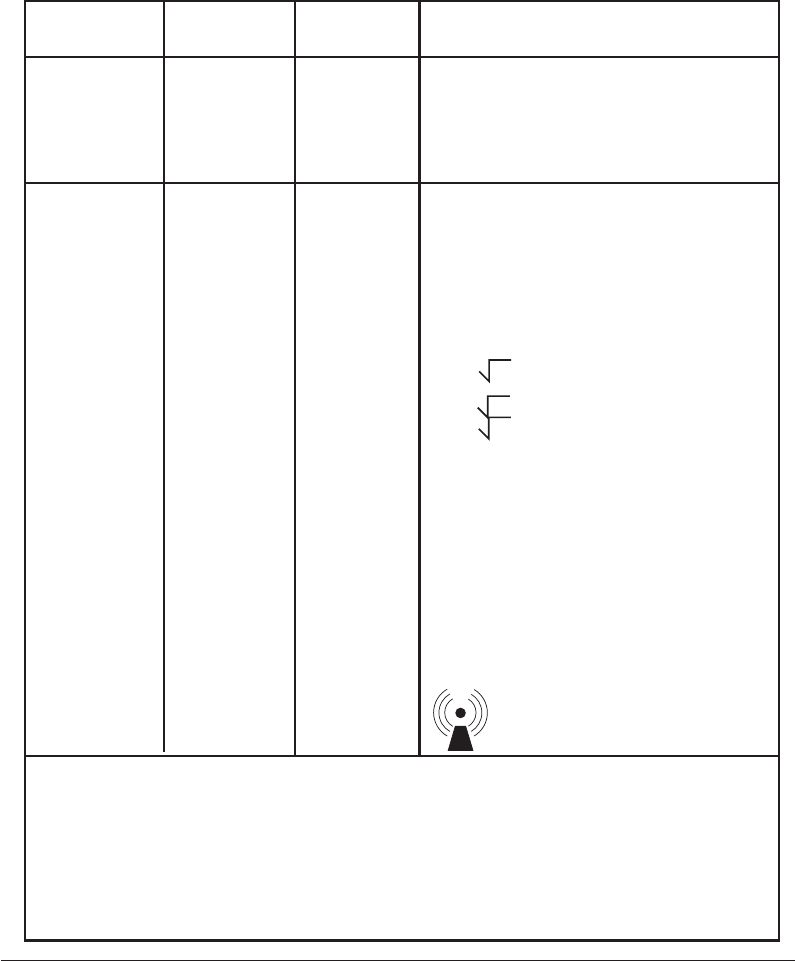
A–3
EMC Information
Immunity Test IEC 60601
Test Level Compliance
Level Electromagnetic Environment -
Guidance
Power frequency magnetic fields should be at
levels characteristic of a typical location in a
typical home or hospital environment.
Portable and mobile RF communications
equipment should be used no closer to any part
of the device, including cables, than the
recommended separation distance calculated
from the equation applicable to the frequency of
the transmitter.
Recommended separation distance
d = 1.2 P
d = 1.2 P 80 MHz to 800 MHz
d = 2.3 P 800 MHz to 2.5 GHz
where P is the maximum output power rating of
the transmitter in watts (W) according to the
transmitter manufacturer and d is the recom-
mended separation distance in meters (m).
Field strengths from fixed RF transmitters, as
determined by an electromagnetic site survey,a
should be less than the compliance level in each
frequency range.b
Interference may occur in the vicinity of
equipment marked with the following symbol:
3 A/m
3 Vrms
3 V/m
Power frequency
(50/60 Hz)
magnetic field
IEC 61000-4-8
Conducted RF
IEC 61000-4-6
Radiated RF
IEC 61000-4-3
3 A/m
3 Vrms
150 kHz to 80 MHz
3 V/m
80 MHz to 2.5 GHz
Guidance and Manufacturer’s Declaration -
Electromagnetic Immunity
This device is intended for use in the electromagnetic environment specified below. The user
of this device should make sure it is used in such an environment.
NOTE 1 At 80 MHz and 800 MHz, the higher frequency range applies.
NOTE 2 These guidelines may not apply in all situations. Electromagnetic propagation is affected by absorption and
reflection from structures, objects, and people.
aField strengths from fixed transmitters, such as base stations for radio (cellular/cordless) telephones and land mobile
radios, amateur radio, AM and FM radio broadcast and TV broadcast cannot be predicted theoretically with
accuracy. To assess the electromagnetic environment due to fixed RF transmitters, an electromagnetic site survey
should be considered. If the measured field strength in the location in which the device is used exceeds the
applicable RF compliance level above, the device should be observed to verify normal operation. If abnormal
performance is observed, additional measures may be necessary, such as re-orienting or relocating the device.
b Over the frequency range 150 kHz to 80 MHz, the field strengths should be less than 3 V/m.

A–4
Alice
®
5 Setup and User’s Guide
Rated Maximum
Power Output of
Transmitter
W
Separation Distance According to Frequency of Transmitter
m
0.01
Recommended Separation Distances between Portable
and Mobile RF Communications Equipment and This
Device
This device is intended for use in an electromagnetic environment in which radiated RF
disturbances are controlled. The customer or the user of this device can help prevent electro-
magnetic interference by maintaining a minimum distance between portable and mobile RF
communications equipment (transmitters) and this device as recommended below, according
to the maximum output power of the communications equipment.
0.1
1
10
100
150 kHz to 80 MHz
d
= 1.2 P
80 MHz to 800 MHz
d
= 1.2 P
800 MHz to 2.5 GHz
d
= 2.3 P
0.12
0.38
1.2
3.8
12
0.12
0.38
1.2
3.8
12
0.23
0.73
2.3
7.3
2.3
For transmitters rated at a maximum output power not listed above, the recommended separa-
tion distance d in meters (m) can be estimated using the equation applicable to the frequency
of the transmitter, where P is the maximum output power rating of the transmitter in watts (W)
according to the transmitter manufacturer.
Note 1: At 80 MHz and 800 MHz, the separation distance for the higher frequency range
applies.
Note 2: These guidelines may not apply in all situations. Electromagnetic propagation is
affected by absorption and reflection from structures, objects, and people.
Limited Warranty
Respironics, Inc. warrants that the system shall be free from defects of workmanship and
materials and will perform in accordance with the product specifications for a period of two (2)
years from the date of sale by Respironics, Inc. to the dealer. If the product fails to perform in
accordance with the product specifications, Respironics, Inc. will repair or replace – at its option
– the defective material or part. Respironics, Inc. will pay customary freight charges from
Respironics, Inc. to the dealer location only. This warranty does not cover damage caused by
accident, misuse, abuse, alteration, and other defects not related to material or workmanship.
Respironics, Inc. disclaims all liability for economic loss, loss of profits, overhead, or consequen-
tial damages which may be claimed to arise from any sale or use of this product. Some states do
not allow the exclusion or limitation of incidental or consequential damages, so the above
limitation or exclusion may not apply to you.
This warranty is given in lieu of all other express warranties. In addition, any implied warranties
– including any warranty of merchantability or fitness for the particular purpose – are limited to
two years. Some states do not allow limitations on how long an implied warranty lasts, so the
above limitation may not apply to you. This warranty gives you specific legal rights, and you
may also have other rights which vary from state to state.
To exercise your rights under this warranty, contact your local authorized Respironics, Inc. dealer
or contact Respironics, Inc. at:
1001 Murry Ridge Lane
Murrysville, Pennsylvania 15668-8550
1-724-387-4000