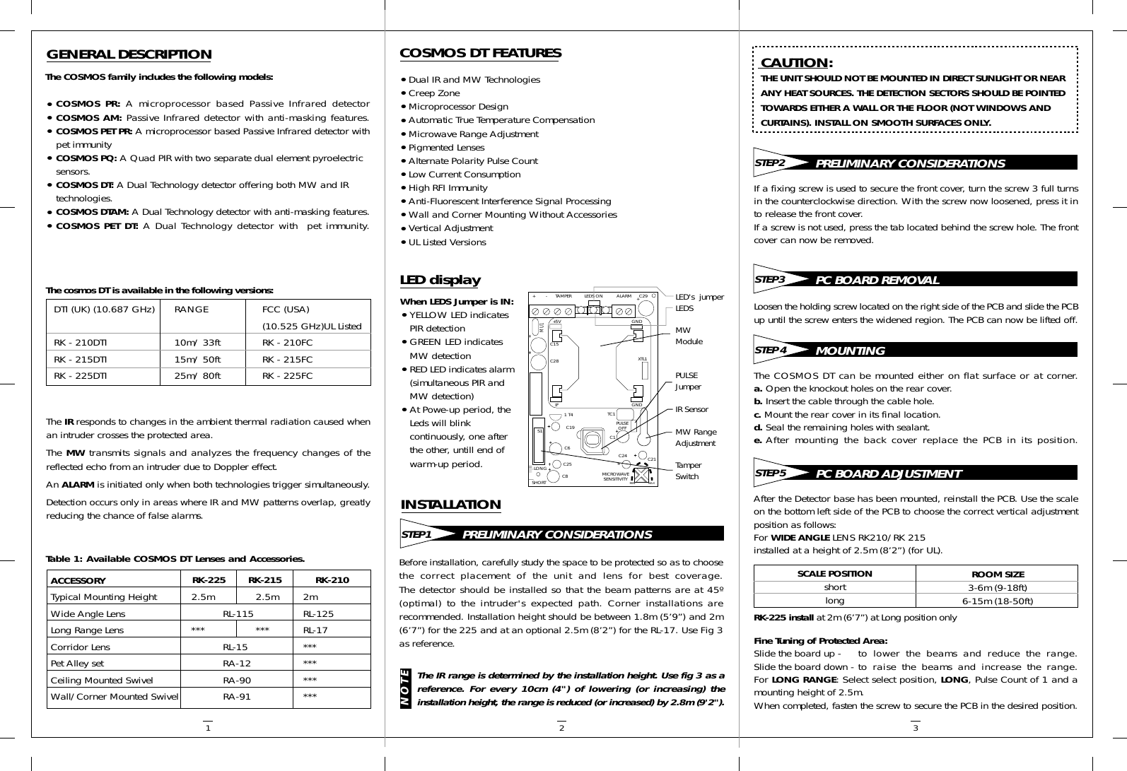
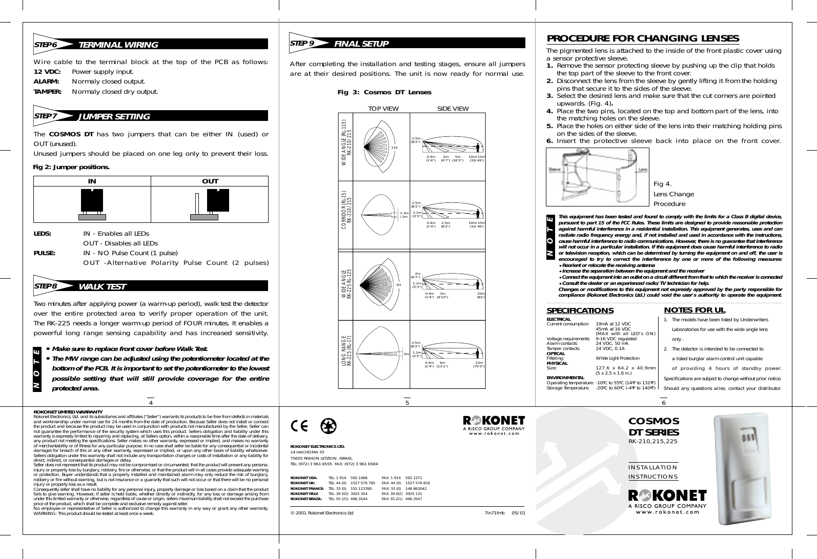
Risco CSMDTN Dual technology motion detector COSMOS DT User Manual with EUT description

Risco Ltd. Dual technology motion detector COSMOS DT with EUT description

Contents

with EUT description

PRELIMINARY CONSIDERATIONSSTEP 1GENERAL DESCRIPTIONThe COSMOS family includes the following models:•COSMOS PR: A microprocessor based Passive Infrared detector•COSMOS AM: Passive Infrared detector with anti-masking features.•COSMOS PET PR: A microprocessor based Passive Infrared detector withpet immunity•COSMOS PQ: A Quad PIR with two separate dual element pyroelectric sensors.•COSMOS DT: A Dual Technology detector offering both MW and IR technologies.•COSMOS DTAM: A Dual Technology detector with anti-masking features.•COSMOS PET DT: A Dual Technology detector with  pet immunity.The IR responds to changes in the ambient thermal radiation caused whenan intruder crosses the protected area.The MW transmits signals and analyzes the frequency changes of thereflected echo from an intruder due to Doppler effect.An ALARM is initiated only when both technologies trigger simultaneously.Detection occurs only in areas where IR and MW patterns overlap, greatlyreducing the chance of false alarms.The cosmos DT is available in the following versions:•Dual IR and MW Technologies•Creep Zone•Microprocessor Design•Automatic True Temperature Compensation•Microwave Range Adjustment•Pigmented Lenses•Alternate Polarity Pulse Count•Low Current Consumption•High RFI Immunity•Anti-Fluorescent Interference Signal Processing•Wall and Corner Mounting Without Accessories•Vertical Adjustment•UL Listed VersionsTable 1: Available COSMOS DT Lenses and Accessories.COSMOS DT FEATURESWhen LEDS Jumper is IN:•YELLOW LED indicates PIR detection•GREEN LED indicates MW detection•RED LED indicates alarm(simultaneous PIR and MW detection)•At Powe-up period, the Leds will blink continuously, one after the other, untill end of warm-up period.LED displayTAMPER+        - LEDS ON ALARM C29+MU1+5VIFGNDGNDS11 T4C19C6C25C8LONGSHORT MICROWAVESENSITIVITYMIN MAXC24 C21C1PULSEOFFTC1XTL1C28C15LED's  jumperLEDSMWModulePULSEJumperIR SensorMW RangeAdjustmentTamperSwitchBefore installation, carefully study the space to be protected so as to choosethe correct placement of the unit and lens for best coverage.The detector should be installed so that the beam patterns are at 45º(optimal) to the intruder's expected path. Corner installations arerecommended. Installation height should be between 1.8m (5’9”) and 2m(6’7”) for the 225 and at an optional 2.5m (8’2”) for the RL-17. Use Fig 3as reference.INSTALLATIONCAUTION:THE UNIT SHOULD NOT BE MOUNTED IN DIRECT SUNLIGHT OR NEARANY HEAT SOURCES. THE DETECTION SECTORS SHOULD BE POINTEDTOWARDS EITHER A WALL OR THE FLOOR (NOT WINDOWS ANDCURTAINS). INSTALL ON SMOOTH SURFACES ONLY.The IR range is determined by the installation height. Use fig 3 as areference. For every 10cm (4") of lowering (or increasing) theinstallation height, the range is reduced (or increased) by 2.8m (9'2").NOTEPRELIMINARY CONSIDERATIONSSTEP 2If a fixing screw is used to secure the front cover, turn the screw 3 full turnsin the counterclockwise direction. With the screw now loosened, press it into release the front cover.If a screw is not used, press the tab located behind the screw hole. The frontcover can now be removed.PC BOARD REMOVALSTEP 3Loosen the holding screw located on the right side of the PCB and slide the PCBup until the screw enters the widened region. The PCB can now be lifted off.MOUNTINGSTEP 4The COSMOS DT can be mounted either on flat surface or at corner.a. Open the knockout holes on the rear cover.b. Insert the cable through the cable hole.c. Mount the rear cover in its final location.d. Seal the remaining holes with sealant.e. After mounting the back cover replace the PCB in its position.PC BOARD ADJUSTMENTSTEP 5After the Detector base has been mounted, reinstall the PCB. Use the scaleon the bottom left side of the PCB to choose the correct vertical adjustmentposition as follows:For WIDE ANGLE LENS RK210/RK 215installed at a height of 2.5m (8’2”) (for UL).Fine Tuning of Protected Area:Slide the board up - to  lower the beams and reduce the range.Slide the board down - to  raise the beams and increase the range.For LONG RANGE: Select select position, LONG, Pulse Count of 1 and amounting height of 2.5m.When completed, fasten the screw to secure the PCB in the desired position.ACCESSORYTypical Mounting Height 2.5m 2.5m 2mWide Angle Lens RL-115 RL-125Long Range Lens *** *** RL-17Corridor Lens RL-15 ***Pet Alley set RA-12 ***Ceiling Mounted Swivel RA-90 ***Wall/Corner Mounted Swivel RA-91 ***RK-225 install at 2m (6’7”) at Long position onlySCALE POSITIONshortlongROOM SIZE3-6m (9-18ft)6-15m (18-50ft)DTI (UK) (10.687 GHz)RK - 210DTIRK - 215DTIRK - 225DTIRANGE10m/ 33ft15m/ 50ft25m/ 80ftFCC (USA)(10.525 GHz)UL ListedRK - 210FCRK - 215FCRK - 225FC1 2 3RK-225 RK-215 RK-210
TERMINAL WIRINGSTEP 6Wire cable to the terminal block at the top of the PCB as follows:12 VDC: Power supply input.ALARM: Normaly closed output.TAMPER: Normaly closed dry output.LEDS: IN - Enables all LEDsOUT - Disables all LEDsPULSE: IN - NO Pulse Count (1 pulse)OUT -Alternative Polarity Pulse Count (2 pulses)The COSMOS DT has two jumpers that can be either IN (used) orOUT (unused).Unused jumpers should be placed on one leg only to prevent their loss.JUMPER SETTINGSTEP 7WALK TESTSTEP 8Two minutes after applying power (a warm-up period), walk test the detectorover the entire protected area to verify proper operation of the unit.The RK-225 needs a longer warm-up period of FOUR minutes. It enables apowerful long range sensing capability and has increased sensitivity.TOP VIEW SIDE VIEWWIDE ANGLE (RL-115)RK-210/215CORRIDOR (RL-15)RK-210/215WIDE ANGLERK-225 RL-125LONG RANGERK-225 (RL-17)1101.3m/2m833m2.5m(8'2")0.4m(1'4") 4m(13'1") 23m(75'5")1.1m(3'3")2m(6'7")0.4m(1'4") 3m(9'10") 25m(82')1.1m(3'3")2.5m(8'2")0.4m(1'4") 2.5m(8'2") 10m/15m(33/49')1.1m(3'3")2.5m(8'2")0.4m(1'4") 2m(6'7") 5m(16'5") 10m/15m(33/49')FINAL SETUPSTEP 9After completing the installation and testing stages, ensure all jumpersare at their desired positions. The unit is now ready for normal use.The pigmented lens is attached to the inside of the front plastic cover usinga sensor protective sleeve.1. Remove the sensor protecting sleeve by pushing up the clip that holds the top part of the sleeve to the front cover.2. Disconnect the lens from the sleeve by gently lifting it from the holding pins that secure it to the sides of the sleeve.3. Select the desired lens and make sure that the cut corners are pointed upwards. (Fig. 4).4. Place the two pins, located on the top and bottom part of the lens, into the matching holes on the sleeve.5. Place the holes on either side of the lens into their matching holding pinson the sides of the sleeve.6. Insert the protective sleeve back into place on the front cover.ROKONET LIMITED WARRANTYRokonet Electronics, Ltd. and its subsidiaries and affiliates ("Seller") warrants its products to be free from defects in materialsand workmanship under normal use for 24 months from the date of production. Because Seller does not install or connectthe product and because the product may be used in conjunction with products not manufactured by the Seller, Seller cannot guarantee the performance of the security system which uses this product. Sellers obligation and liability under thiswarranty is expressly limited to repairing and replacing, at Sellers option, within a reasonable time after the date of delivery,any product not meeting the specifications. Seller makes no other warranty, expressed or implied, and makes no warrantyof merchantability or of fitness for any particular purpose. In no case shall seller be liable for any consequential or incidentaldamages for breach of this or any other warranty, expressed or implied, or upon any other basis of liability whatsoever.Sellers obligation under this warranty shall not include any transportation charges or costs of installation or any liability fordirect, indirect, or consequential damages or delay.Seller does not represent that its product may not be compromised or circumvented; that the product will prevent any persona;injury or property loss by burglary, robbery, fire or otherwise; or that the product will in all cases provide adequate warningor protection. Buyer understands that a properly installed and maintained alarm may only reduce the risk of burglary,robbery or fire without warning, but is not insurance or a guaranty that such will not occur or that there will be no personalinjury or property loss as a result.Consequently seller shall have no liability for any personal injury, property damage or loss based on a claim that the productfails to give warning. However, if seller is held liable, whether directly or indirectly, for any loss or damage arising fromunder this limited warranty or otherwise, regardless of cause or origin, sellers maximum liability shall not exceed the purchaseprice of the product, which shall be complete and exclusive remedy against seller.No employee or representative of Seller is authorized to change this warranty in any way or grant any other warranty.WARNING: This product should be tested at least once a week.ROKONET ELECTRONICS LTD.14 HACHOMA ST.75655 RISHON LETZION. ISRAEL.TEL: (972) 3 961 6555  FAX: (972) 3 961 65847in71fmb© 2001 Rokonet Electronics Ltd05/01TEL: 1 914TEL: 44 (0)TEL: 33 (0)TEL: 39 (02)TEL: 55 (21)FAX: 1 914FAX: 44 (0)FAX: 33 (0)FAX: 39 (02)FAX: 55 (21)ROKONET USA:ROKONET UK:ROKONET FRANCE:ROKONET ITALY:ROKONET BRAZIL:592 10681527 576 765155 1233903925 354496.3544592 12711527 576 816148 8630423925 131496.3547Fig 2: Jumper positions.PROCEDURE FOR CHANGING LENSESFig 4.Lens ChangeProcedureSPECIFICATIONSELECTRICALCurrent consumption: 19mA at 12 VDC45mA at 16 VDC(MAX with all LED's ON)Voltage requirements: 9-16 VDC regulatedAlarm contacts:  24 VDC, 50 mATamper contacts: 24 VDC, 0.1AOPTICALFiltering: White Light ProtectionPHYSICALSize: 127.6 x 64.2 x 40.9mm(5 x 2.5 x 1.6 in.)ENVIRONMENTALOperating temperature: -10ºC to 55ºC (14ºF to 131ºF)Storage Temperature: -20ºC to 60ºC (-4ºF to 140ºF)1. The models have been listed by Underwriters Laboratories for use with the wide angle lens only .2. The detector is intended to be connected to a listed burglar alarm control unit capable of providing 4 hours of standby power.Specifications are subject to change without prior notice.Should any questions arise, contact your distributor.NOTES FOR ULCOSMOSDT SERIESRK-210,215,225INSTALLATIONINSTRUCTIONSFig 3: Cosmos DT Lenses4IN OUTNOTE•Make sure to replace front cover before Walk Test.•The MW range can be adjusted using the potentiometer located at thebottom of the PCB. It is important to set the potentiometer to the lowestpossible setting that will still provide coverage for the entireprotected area.5 6This equipment has been tested and found to comply with the limits for a Class B digital device,pursuant to part 15 of the FCC Rules. These limits are designed to provide reasonable protectionagainst harmful interference in a residential installation. This equipment generates, uses and canradiate radio frequency energy and, if not installed and used in accordance with the instructions,cause harmful interference to radio communications. However, there is no guarantee that interferencewill not occur in a particular installation. If this equipment does cause harmful interference to radioor television reception, which can be determined by turning the equipment on and off, the user isencouraged to try to correct the interference by one or more of the following measures:•Reorient or relocate the receiving antenna•Increase the separation between the equipment and the receiver•Connect the equipment into an outlet on a circuit different from that to which the receiver is connected•Consult the dealer or an experienced radio/TV technician for help.Changes or modifications to this equipment not expressly approved by the party responsible forcompliance (Rokonet Electronics Ltd.) could void the user's authority to operate the equipment.NOTE

Navigation menu