Risco RK315DT Motion Detector User Manual 5IN315DT b
Risco Ltd. Motion Detector 5IN315DT b
UserManual.wiki
>
Risco
>
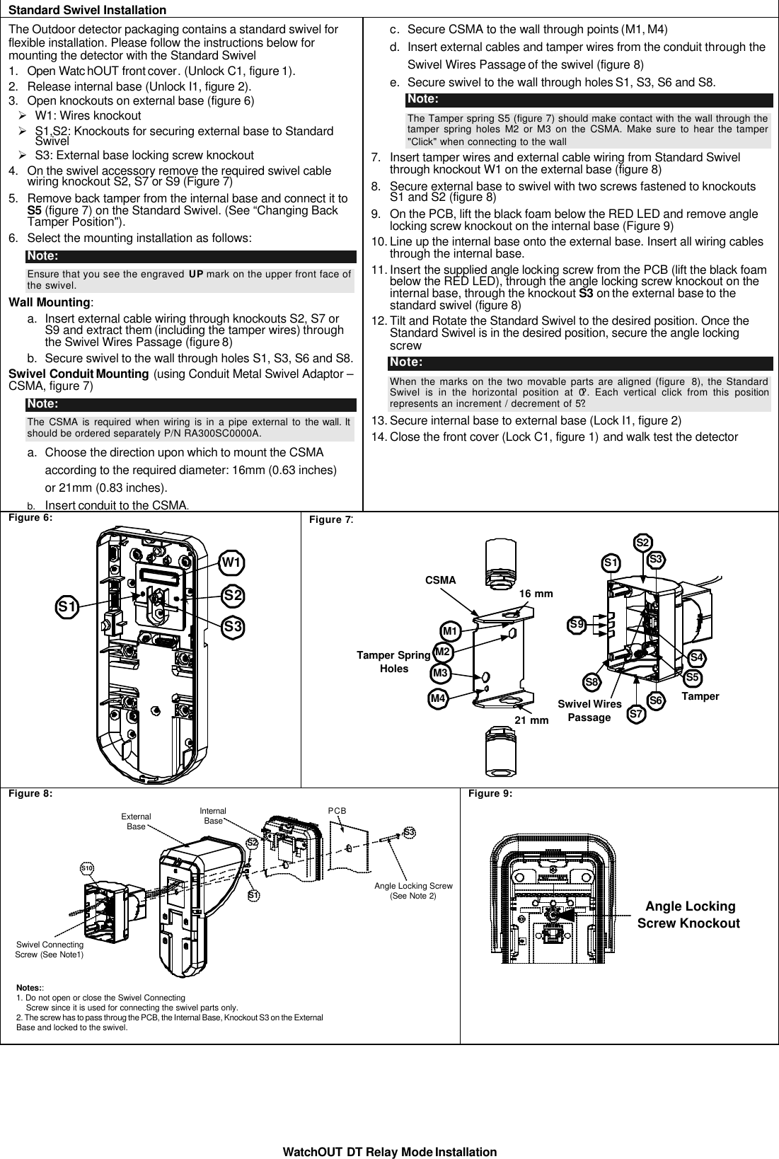
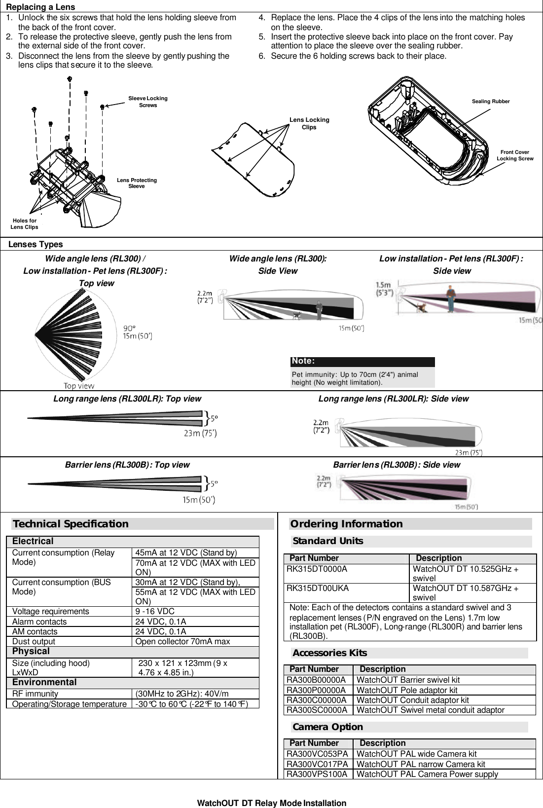
RK315DT User Manual
Users Manual
Navigation menu
Upload a User Manual
Namespaces
Wiki Guide
HTML
PDF
Info
Views
User Manual
Discussion / Help
Navigation