Users Manual
Dual Technology Outdoor Detector
R
Re
el
la
ay
y
M
Mo
od
de
e
I
In
ns
st
ta
al
ll
la
at
ti
io
on
n
I
In
ns
st
tr
ru
uc
ct
ti
io
on
ns
s
WatchOUT DT Relay Mode Installation
WatchOUT DT Relay Mode Installation
WatchOUT Dual Technology Outdoor Detector: Relay Mode Installation
Rokonet’s Dual Technology Outdoor detector, WatchOUT, is a unique detector with signal processing based on two Passive Infrared (PIR)
channels and two Microwave (MW) channels. The detector can operate as a regular relay detector connected to any control panel, or as a BUS
accessory when connected to Rokonet’s ProSYS control panel via the RS485 BUS, thus having unique remote control and diagnostic
capabilities.
The following instructions describe the installation of the WatchOUT in Relay mode. For detailed information regarding BUS mode installation
refer to BUS mode installation instructions (5IN315DTB)
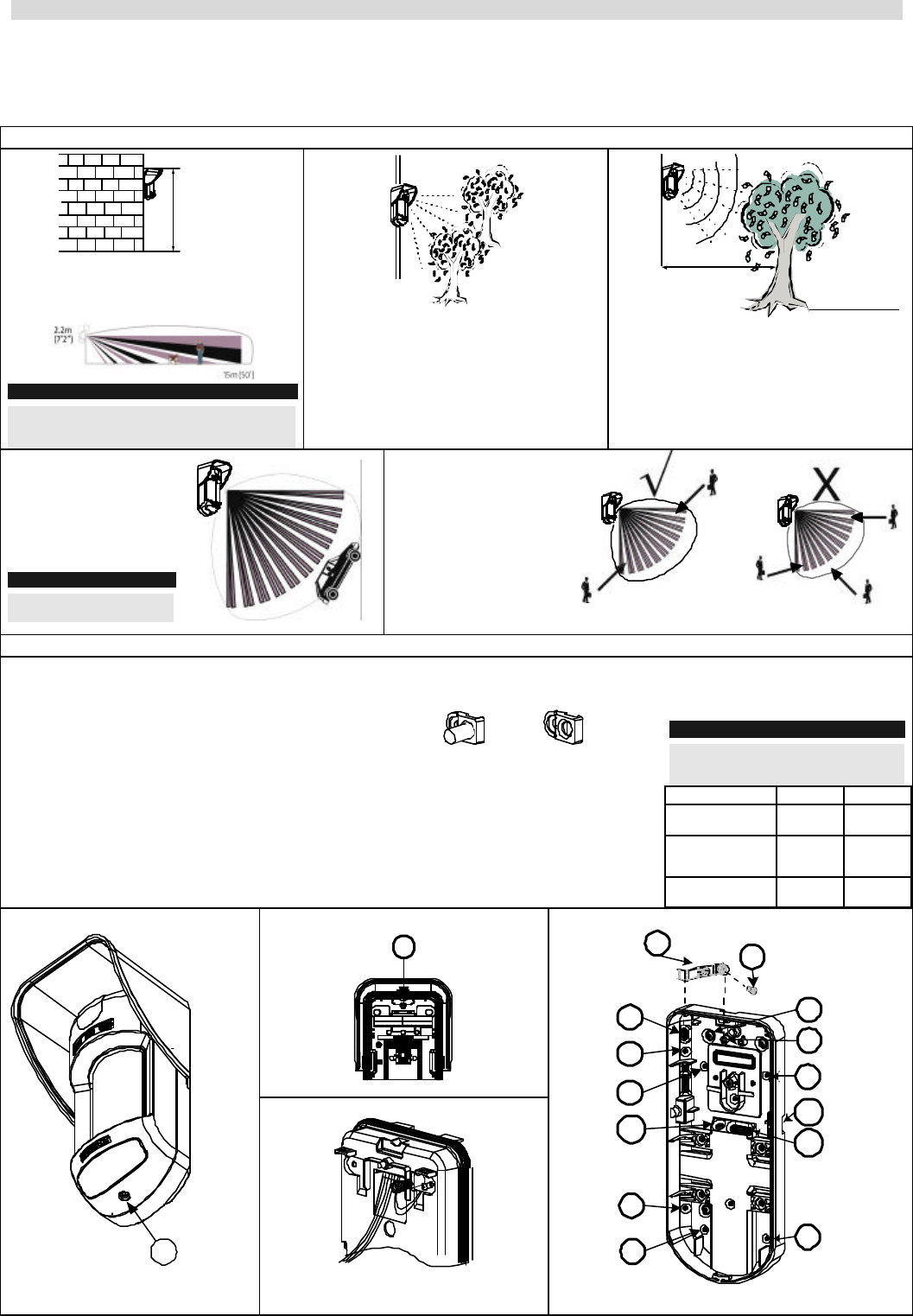
Mounting Considerations
1m - 2.7m
(3'3" - 8'9")
Optional Height: 1m – 2.7m (3'3"-8'9")
Typical Height: 2.2m (7'2")
Default Lens: Wide angle 15m (50') 90°
Note:
For low installations, below 1.7m (5'6") in which pet
immunity is required, use the supplied RL300F lens
(Low wall or fence installations)
If possible avoid pointing the detector to
moving objects (swaying trees, bushes etc)
Out of
Detection Range
Keep distance of
minimum 5m (16')
from moving objects
5m (16')
Ensure any objects do not obstruct the field of
view for both technologies. Pay attention to
growing trees or bushes , plants with big
moving leaves etc.
For installations with
extensive vehicle traffic or
targets beyond the
required detection range it
is recommended to adjust
the MW sensitivity and/or
to tilt the detector down.
Note:
Tilting the detector down may
reduce the pet immunity
For optimum detection,
select a location that is
likely to intercept an
intruder moving across
the coverage pattern at a
45° trajectory.
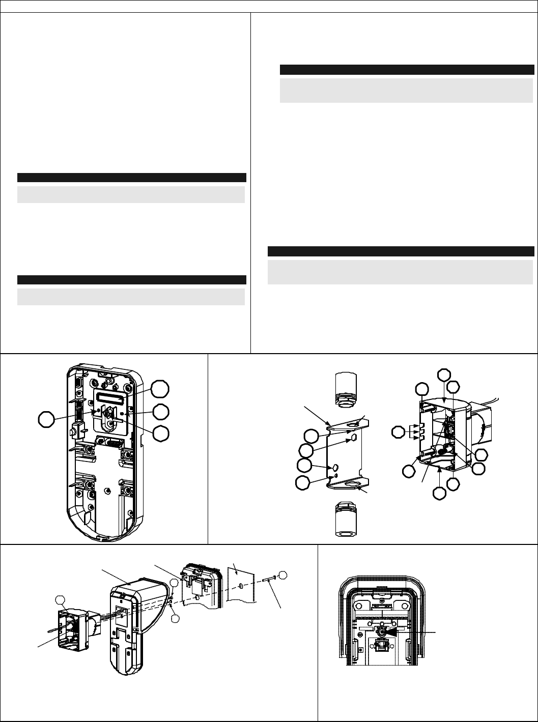
Wall Mount Installation
1. Open Watc hOUT front cover. (Unlock C1, figure 1).
2. Release internal base (unlock I1, figure 2).
3. Select mounting installation as follows:
Flat Mounting:
a. Open knockouts on external base (figure 3)
Ø B1-B4: Wall mounting knockouts .
Ø T1 : Back tamper knockout
Ø W2 / W3: Wire entry knockouts .
45° angle Mounting (Left side mounting)
a. Open knockouts on external base (figure 3)
Ø L1, L2 : Left mounting knockouts
Ø T3 : Left tamper knockout
Ø W2 / W3: Wire entry knockouts
b. Remove tamper spring
c. Replace tamper bracket 1 with supplied
flat tamper bracket 2.
1 2
d. Insert tamper lever B onto T5 and T3
and secure screw A (figure 3)
4. Insert external wires through external
base W2, W3. (figure 3)
5. Secure external base to the wall.
6. Insert external wires and tamper wires
through internal base. (figure 4)
7. Secure internal base to external base
(lock I1, figure 2).
8. Close the front cover (Lock C1,
figure 1) after wiring and setting
Dip switches.
9. Walk test the detector
Note:
For 45° right side installation use the
equivalent units on the external base as
follows:
Left Right
Mounting
Knockouts L1, L2 R1, R2
Tamper
spring
knockouts
T1,T3 T2,T4
Tamper
screw anchor T5 T6
Figure 2:
I1
Figure 1:
C1
Figure 4:
Figure 3:
Tamper
Lever
T1
T5
B2
W2
B3
B4
L2
W3
B1
L1
T3
A
B
W9
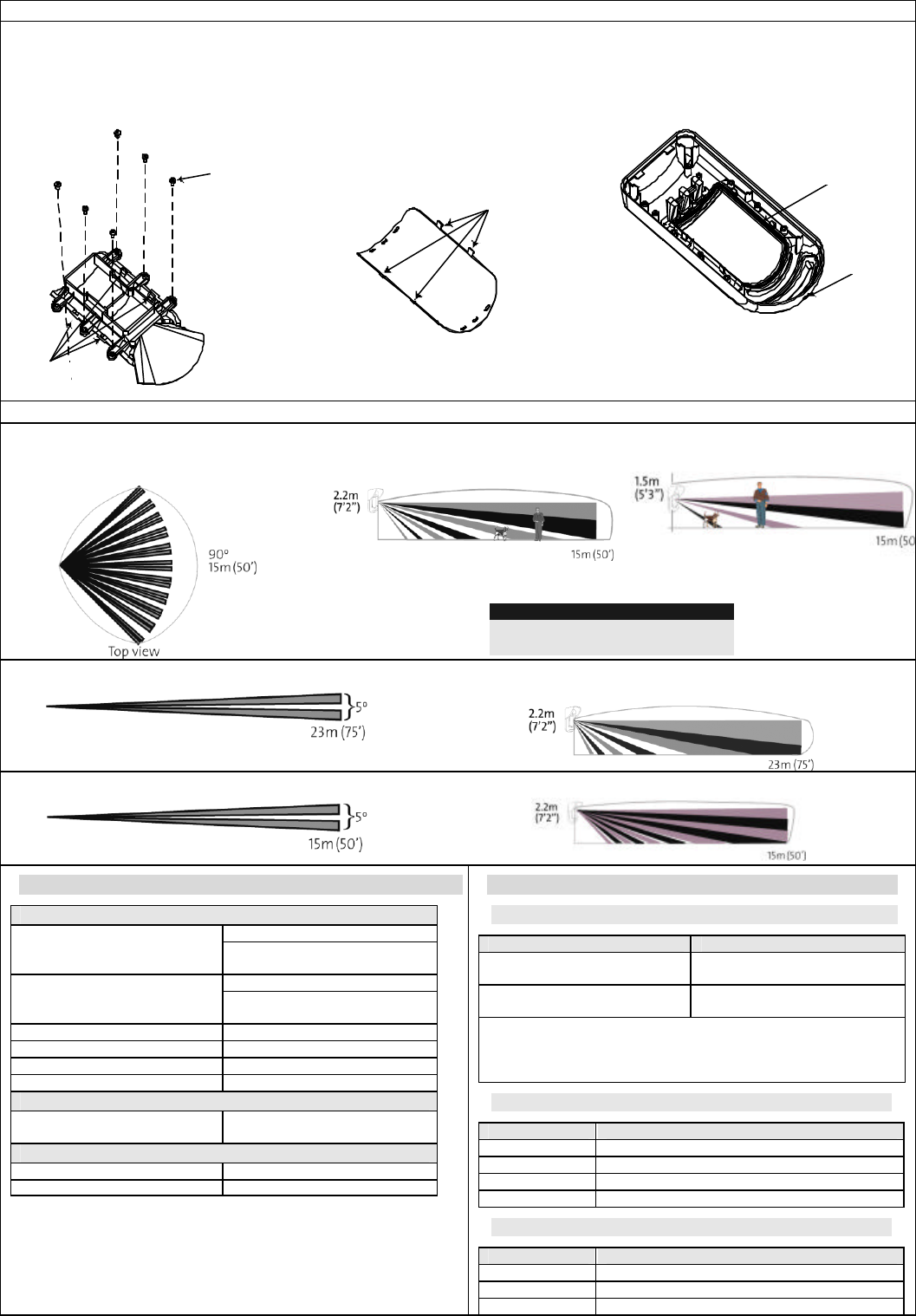
WatchOUT DT Relay Mode Installation
Changing Back Tamper position:
The back tamper is by default secured on the right side of the internal base (Rear
view). If you wish to move it to the left side (rear view), do the following (Figure 5):
1. Remove tamper screw 1 in order to release the tamper from position 7.
2. Ensure tamper spring 2 rests over tamper wire base 4.
3. Ensure plastic tamper bracket 3 rests over both 2 and 4.
4. Secure tamper screw 1 into 3 over position 6.
Notes:
1. Verify that you hear a "Click" when attaching the tamper spring to the wall
2. For pole installation the tamper can be moved to the bottom right-hand side of the internal base.
Figure 5:
Left Side
Tamper Right Side
Tamper
1
3
67
5
4
2
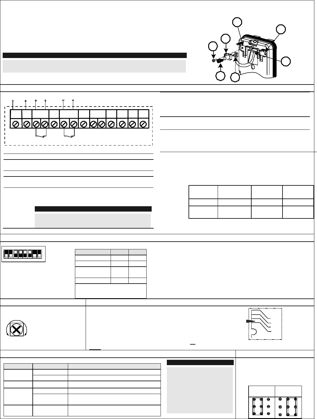
Terminal Wiring
+-SET/
UNSET
LEDs
ENABL
AM
YEL
FREE
ALARM TAMPER GREEN
FREE DUST TEST
12VDC
N.C N.C WatchOUT DT - PCB
+,- 12 VDC
ALARM N.C relay, 24VDC , 0.1A
FREE
YEL This terminal is a free pin that can be used to connect
wires and EOL resistors
TAMPER N.C relay, 24VDC , 0.1A
FREE
GREEN This terminal is a free pin that can be used to connect
wires and EOL resistors
AM Normally closed AM relay output (24VDC, 0.1A)
indicates Anti Masking alarm or any trouble in the
detector (Not including dust/ dirty lens).
Note:
When a vibration detector is installed and DP8 is defined as
Enabled this relay also opens momentarily when vibration
event occurs
LED
ENABL E
Used to remotely control the LEDs when DIP1 is set to
ON.
Enable: input is +12V OR no terminal connection
Disable: Connect the input to 0V
DUST N.O. collector max 70 mA. Indicates that the lens is dirty
and requires cleaning.
TEST Used to perform remote alarm testing to the detector by
applying 0 volts to this terminal.
Success: Alarm relay is momentary opened.
Failure: AM relay is opened
SET/
UNSET This input enables to control Anti-masking and LEDs
operation in accordance to the system status, Set (Arm) /
Unset (Disarm).
While the system is armed this feature prevents an
intruder from gaining knowledge of the detector’s status
and disables Anti-masking detection.
System
Status Input
Status AM
Relay
LEDs
Set (Arm) 0V Off Off
Unset
(Disarm) 12V or no
connection On* On**
* DIP7 is ON (Anti masking enabled)
** DIP1 is ON (LEDs enabled) and LEDs ENABLE input terminal is
enabled (+12V OR no terminal connection)
Dip switch Settings
1 2 3 4 5 6 7 8
ON Factory
Default
DIP 1: LEDs operation
On: LEDs enabled
Off: LEDs disabled
DIP 2-3: Detection Sensitivity
Sensitivity DIP2 DIP3
Low Off Off
Mid Off On
Normal
(Default) On Off
Maximum* On On
* In maximum sensitivity sway
recognition is disabled to achieve
maximum sensitivity
DIP 4: Alarm condition
On: PIR or MW
Off: PIR + MW
DIP 5: Detector's optics
On: Barrier / Long range
Off: Wide angle
DIP 6: Red LED /3 LED
On: Red LED only
Off: 3 LEDs
DIP 7: Anti masking operation
On: Enabled
Off: Disabled
DIP 8: Vibration detection (Only
when the vibration sensor is
installed)
On: Enabled
Off: Disabled
Microwave Adjustment Walk test
Adjust Microwave coverage area by
using the trimmer on the PCB
MIN MAX
Two minutes after applying power, walk test the protected area to verify
proper operation.
For installations on uneven surfaces slide the PCB inside the internal
base to the appropriate setting according to the desired height (1.0m,
1.5m, 2.2m, 2.7m) as printed on the bottom left corner of the PCB or
use the standard swivel accessory.
For reducing the detection range slide the PCB up or tilt the swivel
down.
1.00M
1.50M
2.20M
2.70M
PCB
LEDs Display Relay Mode / Bus Mode Jumper
LED State Description
Steady Indicates PIR detection
YELLOW Flashing Indicates AM (Anti mask) detection
GREEN Steady Indicates MW detection
Steady Indicates ALARM
RED Flashing Indicates malfunctioned communication
with ProSYS (BUS mode only)
All LEDs Flashing (One
after another) Unit initialization on power up.
Notes:
1. DIP-Switch 1 should be in ON
position to enable LED indications.
2. Only one LED is active at any
one time. For example, in the case
of both PIR and MW detection,
either the steady YELLOW LED or
the steady GREEN LED is
displayed (the first to detect),
followed by the Alarm RED LED
J-BUS jumper (located on the
PCB between the red and green
LEDs) is used to define the
detector’s mode of operation as
follows:
Relay
Mode BUS
Mode
WatchOUT DT Relay Mode Installation
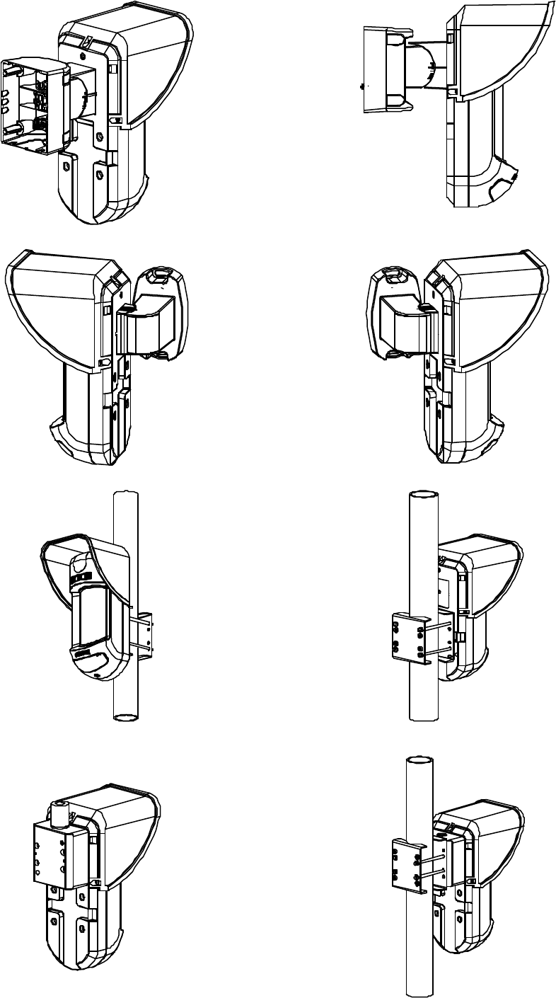
Standard Swivel Installation
The Outdoor detector packaging contains a standard swivel for
flexible installation. Please follow the instructions below for
mounting the detector with the Standard Swivel
1. Open Watc hOUT front cover. (Unlock C1, figure 1).
2. Release internal base (Unlock I1, figure 2).
3. Open knockouts on external base (figure 6)
Ø W1: Wires knockout
Ø S1,S2: Knockouts for securing external base to Standard
Swivel
Ø S3: External base locking screw knockout
4. On the swivel accessory remove the required swivel cable
wiring knockout S2, S7 or S9 (Figure 7)
5. Remove back tamper from the internal base and connect it to
S5 (figure 7) on the Standard Swivel. (See “Changing Back
Tamper Position").
6. Select the mounting installation as follows:
Note:
Ensure that you see the engraved UP mark on the upper front face of
the swivel.
Wall Mounting:
a. Insert external cable wiring through knockouts S2, S7 or
S9 and extract them (including the tamper wires) through
the Swivel Wires Passage (figure 8)
b. Secure swivel to the wall through holes S1, S3, S6 and S8.
Swivel Conduit Mounting (using Conduit Metal Swivel Adaptor –
CSMA, figure 7)
Note:
The CSMA is required when wiring is in a pipe external to the wall. It
should be ordered separately P/N RA300SC0000A.
a. Choose the direction upon which to mount the CSMA
according to the required diameter: 16mm (0.63 inches)
or 21mm (0.83 inches).
b. Insert conduit to the CSMA.
c. Secure CSMA to the wall through points (M1, M4)
d. Insert external cables and tamper wires from the conduit through the
Swivel Wires Passage of the swivel (figure 8)
e. Secure swivel to the wall through holes S1, S3, S6 and S8.
Note:
The Tamper spring S5 (figure 7) should make contact with the wall through the
tamper spring holes M2 or M3 on the CSMA. Make sure to hear the tamper
"Click" when connecting to the wall
7. Insert tamper wires and external cable wiring from Standard Swivel
through knockout W1 on the external base (figure 8)
8. Secure external base to swivel with two screws fastened to knockouts
S1 and S2 (figure 8)
9. On the PCB, lift the black foam below the RED LED and remove angle
locking screw knockout on the internal base (Figure 9)
10. Line up the internal base onto the external base. Insert all wiring cables
through the internal base.
11. Insert the supplied angle locking screw from the PCB (lift the black foam
below the RED LED), through the angle locking screw knockout on the
internal base, through the knockout S3 on the external base to the
standard swivel (figure 8)
12. Tilt and Rotate the Standard Swivel to the desired position. Once the
Standard Swivel is in the desired position, secure the angle locking
screw
Note:
When the marks on the two movable parts are aligned (figure 8), the Standard
Swivel is in the horizontal position at 0?. Each vertical click from this position
represents an increment / decrement of 5?.
13. Secure internal base to external base (Lock I1, figure 2)
14. Close the front cover (Lock C1, figure 1) and walk test the detector
Figure 6:
W1
S1 S2
S3
Figure 7:
21 mm
16 mm
Tamper Spring
Holes
CSMA
M1
M2
M3
M4 Tamper
Swivel Wires
Passage
S1
S2
S3
S4
S5
S6
S7
S8
S9
Figure 8:
S1
S10
External
Base
Internal
Base PCB
S3
Notes::
1. Do not open or close the Swivel Connecting
Screw since it is used for connecting the swivel parts only.
2. The screw has to pass throug the PCB, the Internal Base, Knockout S3 on the External
Base and locked to the swivel.
Swivel Connecting
Screw (See Note1)
S2
Angle Locking Screw
(See Note 2)
Figure 9:
Angle Locking
Screw Knockout
WatchOUT DT Relay Mode Installation
Replacing a Lens
1. Unlock the six screws that hold the lens holding sleeve from
the back of the front cover.
2. To release the protective sleeve, gently push the lens from
the external side of the front cover.
3. Disconnect the lens from the sleeve by gently pushing the
lens clips that secure it to the sleeve.
4. Replace the lens. Place the 4 clips of the lens into the matching holes
on the sleeve.
5. Insert the protective sleeve back into place on the front cover. Pay
attention to place the sleeve over the sealing rubber.
6. Secure the 6 holding screws back to their place.
Sleeve Locking
Screws
Lens Protecting
Sleeve
Holes for
Lens Clips
Lens Locking
Clips
Sealing Rubber
Front Cover
Locking Screw
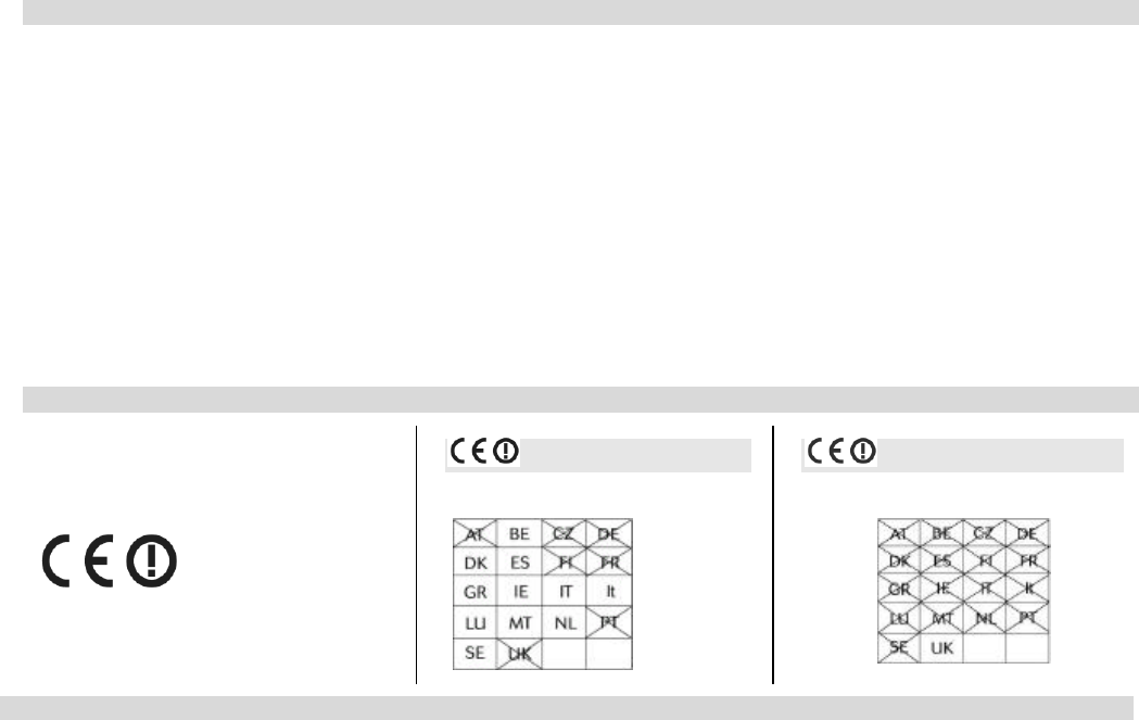
Lenses Types
Wide angle lens (RL300):
Side View
Low installation - Pet lens (RL300F) :
Side view
Wide angle lens (RL300) /
Low installation - Pet lens (RL300F) :
Top view
Note:
Pet immunity: Up to 70cm (2'4") animal
height (No weight limitation).
Long range lens (RL300LR): Top view
Long range lens (RL300LR): Side view
Barrier lens (RL300B): Top view
Barrier lens (RL300B): Side view
Technical Specification
Electrical
45mA at 12 VDC (Stand by) Current consumption (Relay
Mode) 70mA at 12 VDC (MAX with LED
ON)
30mA at 12 VDC (Stand by), Current consumption (BUS
Mode) 55mA at 12 VDC (MAX with LED
ON)
Voltage requirements 9 -16 VDC
Alarm contacts 24 VDC, 0.1A
AM contacts 24 VDC, 0.1A
Dust output Open collector 70mA max
Physical
Size (including hood)
LxWxD 230 x 121 x 123mm (9 x
4.76 x 4.85 in.)
Environmental
RF immunity (30MHz to 2GHz): 40V/m
Operating/Storage temperature -30°C to 60°C (-22°F to 140°F)
Ordering Information
Standard Units
Part Number Description
RK315DT0000A WatchOUT DT 10.525GHz +
swivel
RK315DT00UKA WatchOUT DT 10.587GHz +
swivel
Note: Each of the detectors contains a standard swivel and 3
replacement lenses (P/N engraved on the Lens) 1.7m low
installation pet (RL300F), Long-range (RL300R) and barrier lens
(RL300B).
Accessories Kits
Part Number Description
RA300B00000A WatchOUT Barrier swivel kit
RA300P00000A WatchOUT Pole adaptor kit
RA300C00000A WatchOUT Conduit adaptor kit
RA300SC0000A WatchOUT Swivel metal conduit adaptor
Camera Option
Part Number Description
RA300VC053PA WatchOUT PAL wide Camera kit
RA300VC017PA
WatchOUT PAL narrow Camera kit
RA300VPS100A
WatchOUT PAL Camera Power supply
WatchOUT DT Relay Mode Installation
FCC Note
This equipment has been tested and found to comply with the limits for a Class B digital device, pursuant to part 15 of the FCC Rules.
These limits are designed to provide reasonable protection against harmful interference in a residential installation. This equipment
generates uses and can radiate radio frequency energy and, if not installed and used in accordance with the instructions, may cause
harmful interference to radio communications. However, there is no guarantee that interference will not occur in a particular installation. If
this equipment does cause harmful interference to radio or television reception, which can be determined by turning the equipment on and
off, the user is encouraged to try to correct the interference by one or more of the following measures:
F Reorient or relocate the receiving antenna.
F Increase the separation between the equipment and the receiver.
F Connect the equipment into an outlet on to a different circuit from that to which the receiver is connected.
F Consult the dealer or an experienced radio/TV technician for help.
Changes or modifications to this equipment which are not expressly approved by the party responsible for compliance (Rokonet Electronics
Ltd.) could void the user's authority to operate the equipment.
FCC ID: JE4RK315DT Valid for P/N RK315DT0000A
RTTE Compliance Statement
Hereby, Rokonet Electronics Ltd, declares
that this equipment is in compliance with the
essential requirements and other relevant
provisions of Directive 1999/5/EC
Clarification
Table for P/N: RK315DT0000A
Clarification
Table for P/N: RK315DT00UKA
Rokonet Limited Warranty
Rokonet Electronics, Ltd. and its subsidiaries and affiliates ("Seller") warrants its products to be free from defects in materials and
workmanship under normal use for 24 months from the date of production. Because Seller does not install or connect the product and
because the product may be used in conjunction with products not manufactured by the Seller, Seller cannot guarantee the performance of
the security system which uses this product. Seller's obligation and liability under this warranty is expressly limited to repairing and replacing,
at Sellers option, within a reasonable time after the date of delivery, any product not meeting the specifications . Seller makes no other
warranty, expressed or implied, and makes no warranty of merchantability or of fitness for any particular purpose.
In no case shall seller be liable for any consequential or incidental damages for breach of this or any other warranty, expressed or implied, or
upon any other basis of liability whatsoever.
Seller's obligation under this warranty shall not include any transportation charges or costs of installation or any liability for direct, indirect, or
consequential damages or delay.
Seller does not represent that its product may not be compromised or circumvented; that the product will prevent any persona; injury or
property loss by burglary, robbery, fire or otherwise; or that the product will in all cases provide adequate warning or protection. Buyer
understands that a properly installed and maintained alarm may only reduce the risk of burglary, robbery or fire without warning, but is not
insurance or a guaranty that such will not occur or that there will be no personal injury or property loss as a result.
Consequently seller shall have no liability for any personal injury, property damage or loss based on a claim that the product fails to give
warning. However, if seller is held liable, whether directly or indirectly, for any loss or damage arising from under this limited warranty or
otherwise, regardless of cause or origin, sellers maximum liability shall not exceed the purchase price of the product, which shall be complete
and exclusive remedy against seller. No employee or representative of Seller is authorized to change this warranty in any way or grant any
other warranty.

WatchOUT DT Relay Mode Installation
USA
Tel. +1 305 592 3820
Fax. +1 305 592 3825
Email: sales@rokonetusa.com
ISRAEL
Tel. +972 (0)3 9637777
Fax. +972 (0)3 9616584
Email: info@rokonet.co.il
www.rokonet.com
UK
Tel. +44 (0)161 655 5500
Fax. +44 (0) 161 655 5501
Email: sales@riscogroup.co.uk
ITALY
Tel. +39 02 392 5354
Fax. +39 02 392 5131
Email: info@rokonet.it
SPAIN
Tel. +34 91 4902133
Fax. +34 91 4902134
Email: sales@rokonet.es
BRAZIL
Tel. +55 11 3661 8767
Fax. +55 11 3661 7783
Email: rokonet@rokonet.com.br
5IN315DT B
© Rokonet Electronics Ltd. 11/05