Rising Digital SECD-10IA-03 SECD-10IA-03 Display Screen User Manual
Shanghai Rising Digital Co.,Ltd. SECD-10IA-03 (S) Display Screen
User Manual

SECD‐10IA‐03User'sManual
|ShanghaiRisingDigitalCo.,Ltd.
SECD‐10IA‐03
User'sManualV1.0

SECD‐10IA‐03User'sManual
|ShanghaiRisingDigitalCo.,Ltd.
Summary
As a vehicle mounted display, SECD-10IA-03 can meet
human-machine interaction, wireless communication and
positioning, body control, video surveillance and other
requirements under construction machinery, special machinery
and other harsh conditions.

SECD‐10IA‐03User'sManual
|ShanghaiRisingDigitalCo.,Ltd.
Directories
Functionandcharacteristics......................................................................................1
1、 Integrationofdisplay,communication,controlandvideosurveillance.................1
2、pecialconfigurationprogramdevelopmentenvironment......................................1
3、 Adapttotheharshenvironment................................................................................1
4、SeamlessconnectionwithRisingremotemonitoringsystem.................................1
Externalinterfacefunctiondescription........................................................................2
1、 Externalcharacteristics..............................................................................................2
2、 34pinconnectorportdefinition................................................................................2
Installationofwiring..............................................................................................................3
1、 size................................................................................................................................3
2、 Installationmethod....................................................................................................3
Descriptionofproductparametersandenvironmentalindicators..............................3
Three:developmentanddebugging.....................................................................................5
1、hardwaredevelopmentplatform................................................................................5
2.、softwaredevelopmentenvironment.........................................................................5
Appendix........................................................................................................................6

SECD‐10IA‐03User'sManual
1|ShanghaiRisingDigitalCo.,Ltd.
Function and characteristics
1、 Integrationofdisplay,communication,controlandvideosurveillance
Show: 10.4 inch, resolution 600x800, industrial TFT LCD screen, resistance
touch control
Communication::
upport GPRS wireless communication, support GPS positioning,
Support CAN communication, 2 channel, compatible J1939/CANOpen/CAN2.0B
protocol
control:
2 AI_V (or AI_I), 2 Road AI_R, 2 Road TI, 4 road PWM (reusable DO)
Video:
Support 4, 4 single camera, segmentation, picture in picture display mode,
NTSC/PAL self recognition
2、 pecialconfigurationprogramdevelopmentenvironment
Man-machine interface: the DGUS configuration software is used to integrate
the common interface display controls.
Control communication: integration of LM Studio integrated development
environment to integrate common functional blocks
3、 Adapttotheharshenvironment
Can be used in cold and hot environment: -25 degree at low
temperature, 65 degree high temperature
Anti - back design of power supply, more than 37V self protection,
prevent burning
Strong vibration, dusty rain, lightning and other environment for
field operation
4、 SeamlessconnectionwithRisingremotemonitoringsystem
Supporttheremoteunlockingmachinetofacilitatethemanagementofcreditor'srights

SECD‐10IA‐03User'sManual
2|ShanghaiRisingDigitalCo.,Ltd.
External interface function description
1、 Externalcharacteristics
2、 34pinconnectorportdefinition
order name function remark
1 CAN2_HCANHigh
2 TI2
3 RSreset
4 +12VOUT12Vouput
5 CAN1_LCANLow
6 CAN1_HCANHigh
7 CAMRA2_V‐ CameranegativeofChannel2
8 GND
9 +5VOUT5Vouput
10 CAN2_LCANLow
11 T11
12 +12VOUT
13 CAMRA1_V+ CamerapositiveofChannel1
14 CAMRA1_V‐CameranegativeofChannel1
15 CAMRA2_V+ CamerapositiveofChannel1
16 CAMRA3_V‐CameranegativeofChannel5
17 SMI
18 AI_R1
19 AI_1
20 AI_2
21 CAMRA4_V+CamerapositiveofChannel4
22 CAMRA4_V‐ CameranegativeofChannel4
23 CAMRA3_V+CamerapositiveofChannel3
24 GNDGND
Pin connector
SECD‐10IA‐03User'sManual
3|ShanghaiRisingDigitalCo.,Ltd.
25 24VinPowerinputrange:12~36VDC
26 AI_R_2
27 PWM3Pwmoutput
28 PWM4Pwmoutput
29 PWM1Pwmoutput
30 PWM2 Pwmoutput
31 reserved
32 reserved
33 GND GND
34 +24Vin Powerinput
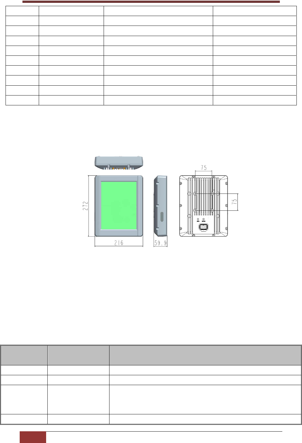
Installation of wiring
1、 size
2、 Installationmethod
4×M6 Screw (including a spring washer, a flat washer)
Description of product parameters and environmental
indicators
Serial
number Name detailed
1 Video input 4,PAL / NTSC signal
2 +12V OUT output 2
3 Signal
communication
CAN:1circuit,Rate of optional,ISO11898 CAN 2.0B、J1939
GSM:1circuit,
GPS link:1 circuit
4 display 10.4inch
SECD‐10IA‐03User'sManual
4|ShanghaiRisingDigitalCo.,Ltd.
resolution:800×600(3RGB)
TFT
5 touch 4Linear resistance touch
6 Conventional
parameters
kernel: TMS320F28335(32 bit DSP),FGPA(video)
Frequency:150MHZ
Power supply:12~36 V.DC
(Recommended voltage 24V.DC,36 V Do not work for a long time)
output voltage:12 V.DC,1A
Consumption of current:0.55 A.DC(24 V.DC)
Power waste:≤ 14W
Video display: pip, 4 division / single
7 work environment
working temperature:- 25 ~ 65 °C
Storage temperature:- 30 ~ 80 °C
Overvoltage protection:37.2 V
Anti vibration:4 - 300 HZ 10mm 5G
Impact resistance:50G 6ms & 11ms
Relative temperature:10%~95 %
Protection grade:IP65
8
Anti-interference
performance of
electrostatic
discharge
Power supply mode: air discharge + 15kV, contact discharge
+ 8kV
No electricity mode: air discharge + 25kV, contact discharge
8kV
9
ISO7637
anti-interference
capability
Power line: ISO7637 - 2 IV level
Signal line: conforming to ISO7637 -3
10 Anti surge grade IEC61000 – 4 – 5 IV
11 size 272 X 216 X 59.9(mm)

SECD‐10IA‐03User'sManual
5|ShanghaiRisingDigitalCo.,Ltd.
Three:developmentanddebugging
1、hardwaredevelopmentplatform
ConnectwiththecontrollerbyCANBus.SupportCAN2.0B,CanOpen,J1939protocol
TheLMUSBemulatorpluginPCbyUSBinterface.AndtheUSBemulatorisconnectwith
thedisplayscreenbyCAN‐bus.LMStudio(thesoftwaredevelopmentenvironment)canbesetup
inPC.Andthehardwaredevelopmentplatformiscompleted.

SECD‐10IA‐03User'sManual
6|ShanghaiRisingDigitalCo.,Ltd.
LMStudio(thesoftwaredevelopmentenvironment)canbesetupinPC.Theusercan
createproject,createpage,addthewidget,generatethescript,downloadprogram,program
debugger.
Appendix
《DGUSScreendevelopmentguide》
《LMProgrammingmanual》
5、The instructions on the camera:
1)Standard specification
This product can signal automatic identification both formats: NTSC, PAL. It is important
to note when replacing different format cameras, need to install the screen after power.
For multiple display, please ensure that the camera used for unified format.
2)Installation Angle
Installed the camera at a vertical angle , please make sure that it can achieve the best
effect of display. Actual situation, please according to the display effect the appropriate
2.、softwaredevelopmentenvironment
LMStudioistheplatformforsoftwareprojectmanagement,codeediting,codecompiling,
codedebugger,codedownloading.WecanuseLMlanguagetodevelopprogram.
UsercandevelopHMIbythewayofgraphicuserinterface(GUI).Weonlyneedtocreate
somewidgetinthedevelopmentenvironment.Thenattachthevaluetothewidgetparameter.
AndwritesomeLMscriptonthebackgroundprogram.GraphicalshowbyLMstudioGUI
moduleisthesametoonewhichisrunninginthedevice.

SECD‐10IA‐03User'sManual
7|ShanghaiRisingDigitalCo.,Ltd.
adjustments.
6、Matters needing attention:
besides controller shell with good grounding, all the sensors are connected to the
controller, the load, and so on input and output points must connect into a closed loop,
which all of the input and output must be connected with the controller corresponding
to;
GPRS 、GPS Antenna installation, pay attention to the antenna will tighten the joint
after use.
FCC Statement
Any Changes or modifications not expressly approved by the party responsible for
compliance could void the user’s authority to operate the equipment.
This device complies with part 15 of the FCC Rules. Operation is subject to the following two
conditions: (1) This device may not cause harmful interference, and
(2) This device must accept any interference received, including interference that may cause
undesired operation.
Note: This equipment has been tested and found to comply with the limits for a Class B digital device,
pursuant to part 15 of the FCC Rules. These limits are designed to provide reasonable protection
against harmful interference in a residential installation. This equipment generates, uses and can
radiate radio frequency energy and, if not installed and used in accordance with the instructions, may
cause harmful interference to radio communications. However, there is no guarantee that interference
will not occur in a particular installation. If this equipment does cause harmful interference to radio or
television reception, which can be determined by turning the equipment off and on, the user is
encouraged to try to correct the interference by one or more of the following measures:
—Reorient or relocate the receiving antenna.
—Increase the separation between the equipment and receiver.
—Connect the equipment into an outlet on a circuit different from that to which the receiver is
connected.
—Consult the dealer or an experienced radio/TV technician for help.
Antenna gain including cable loss must not exceed 4.95dBi in GSM850/GPRS850,2dBi in GSM1900/
GPRS1900 for the purpose of satisfying the requirements of CFR47 2.1091.The antenna(s) used for
this transmitter must be installed to provide a separation distance of at least 20 cm form all persons
and must not be co-located or operated in conjunction with any antenna or transmitter, except in
accordance with FCC multi-transmitter evaluation procedure.Compliance of this device in all final
product confiqurations is the responsibility of the Grantee.