Rising Digital SECD-5I0A Display screen User Manual
Shanghai Rising Digital Co.,Ltd. Display screen Users Manual
User Manual
SECD‐5I0A‐03 user manual
Shanghai Rising Digital Co.,Ltd.
SECD-5I0A-03&SECD-5I0A-03(S)
&SECD-5I0B-03(S)
USER MANUAL
Document
Number:
Dense level:
Version Number: V1.2

SECD‐5I0A‐03 user manual
CATALOG
One: Function....................................................................................................................................................1
1、Powerful function, good sharp.................................................................................................................................1
2、LM development environment.................................................................................................................................3
Two: Function definition.................................................................................................................................. 4
1、interface definition...................................................................................................................................................4
2、size............................................................................................................................................................................ 5
3、34 pin interface definition........................................................................................................................................5
Three: development and debugging................................................................................................................7
1、hardware development platform.............................................................................................................................7
2.、software development environment.......................................................................................................................7
3、example.................................................................................................................................................................... 8
3.1、graphic development........................................................................................................................................ 8
3.3、download the photos and program................................................................................................................ 11
Four: connect the controller...........................................................................................................................13

SECD‐5I0A‐03 user manual
1
One: Function
1、Powerful function, good sharp
control、display、GPS/GPRS/WIF communication
input and output signals,for sampling and controlling
good sharp:PAD sharp
1) Voltage input:
channel:6
signal:0〜5V.DC
precision:0.5%
resolution:0.025%
2) Resistance input :
channel:2
precision:0.5%
resolution:0.025%
3) Discrete input(low level):
channel:5
signal peak:0〜40V.DC
frequency:0Hz〜1KHz
4) Periodic input:
channel:1
signal peak:1.2〜36V.DC
range:10Hz〜70KHz

SECD‐5I0A‐03 USER MANUAL
2
precision:0.1%
5) PWM output:
channel:6
frequency:50〜2.55kHz
current:0〜1.5A
precision:1%
resolution:0.025%
features:overpressure、short circuit protection
6) Motordriveroutput:
channel:4(one stepper motor)
contact capacity:40V.DC 1.2A
frequency:0Hz〜130Hz
features:overpressure、short circuit protection
7) Digital output:
channel:6
contact capacity:36V.DC 1.8A
frequency:0Hz〜1KHz
8) Communication interface:
CAN:1circuit,Rate of optional,ISO11898 CAN 2.0B、J1939
Communications link:1circuit,4G/GSM
North American version‐frequency band LTE‐FDD B2/4/5/12/17,WCDMA B2/4/5,GSM 850/1900
The European version—frequency band LTE‐FDD B1/3/5/7/8/20,WCDMA B1/5/8,GSM

SECD‐5I0A‐03 USER MANUAL
3
850/900/1800/1900
The Chinese version—frequency band LTE‐FDD B1/3/8,LTE‐TDD B38/39/40/41,WCDMA B1,
TD‐SCDMA B34/39,GSM 900/1800
GPS link:1circuit
9) Display parameters:
resolution:640×480(3RGB)
10) Other indicators
kernel:ARM Contex‐M4(32bit)
proposed kernel:168MHz
duty cycle:≤5ms
power supply:9〜36V.DC(Under the recommended voltage 24 v DC 36 v can't work for a long time)
output voltage:5V.DC,0.75A
Current consumption:0.2A.DC(24V.DC)
Working temperature:‐20〜+65℃
Storage temperature:‐25〜+80℃
overvoltage protection:37.2V
high temperature protection:80℃
vibration level: 6.8g, 8.3‐400HZ
protection grade:IP65,all‐round protection
relative humidity:10%〜90%
overall dimensions:120mm×88mm×51.5mm
2、LM development environment
LM Studio development environment which is based on IEC61149

SECD‐5I0A‐03 USER MANUAL
4
LM Studio GUI module provide the graphic user interface(GUI)
Lots of function blocks which can be used to develop graphic and program quickly
Two: Function definition
1、interface definition

SECD‐5I0A‐03 USER MANUAL
5
2、size
4×M6 screws
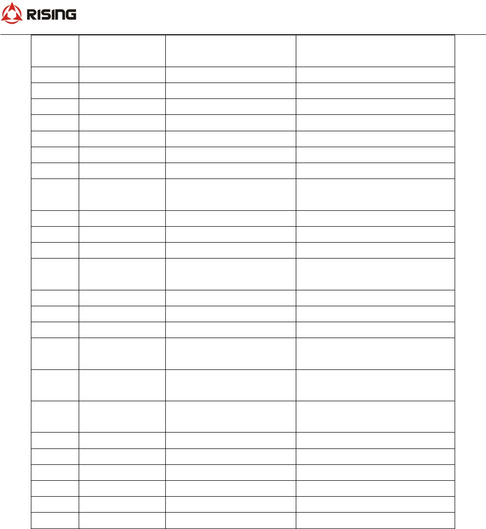
3、34 pin interface definition
NO NAME FUNCTION REMARK
1CAN_L CANLow Communicate with controller;
Program download and debug
2CAN_H CAN High
3 TI1 Periodic input
4 AI_V5 Analog input Active High
5 AI_V6 Analog input Active High
6 DI_L5 Digital input Active low
7 RS Reset Ground beyond 3s
8GND Ground
9 +5VOUT +5V Output
SECD‐5I0A‐03 USER MANUAL
6
10 PWM_1/DO_1 Pulse‐width
Modulation/Digital Output
11 A+ Moto A+
12 DI_L1 Digital Input Active low
13 DI_L2 Digital Input Active low
14 DI_L3 Digital Input Active low
15 DI_L4 Digital Input Active low
16 A‐Moto A‐
17 SMI The Ignition Signal
18 PWM_2/DO_2 Pulse‐width
Modulation/Digital Output
19 B+ Moto B+
20 B‐Moto B‐
21 AI_V1 Analog input Voltage type
22 PWM_6/DO_6 Pulse‐width
Modulation/Digital Output
23 AI_R1 Analog Input Resistance type
24 GND Ground
25 +24VIN Power Range:12~36VDC
26 PWM_3/DO_3 Pulse‐width
Modulation/Digital Output
27 PWM_4/DO_3 Pulse‐width
Modulation/Digital Output
28 PWM_5/DO_4 Pulse‐width
Modulation/Digital Output
29 AI_V2 Analog Input Voltage type
30 AI_V3 Analog Input Voltage type
31 AI_R2 Analog Input Resistance type
32 AI_V4 Analog Input Voltage type
33 GND Ground
34 +24VIN Power Range:12~36VDC

SECD‐5I0A‐03 USER MANUAL
7
Three: development and debugging
1、hardware development platform
The LM USB emulator plug in PC by USB interface. And the USB emulator is connect with the display screen
by CAN‐bus. LM Studio (the software development environment) can be setup in PC. And the hardware
development platform is completed.
2.、software development environment
LM Studio is the platform for software project management, code editing, code compiling, code debugger,
code downloading. We can use LM language to develop program.
User can develop HMI by the way of graphic user interface(GUI) . We only need to create some widget in the
development environment. Then attach the value to the widget parameter. And write some LM script on the
background program. Graphical show by LM studio GUI module is the same to one which is running in the
device.

SECD‐5I0A‐03 USER MANUAL
8
Figure 1 LM Studio setup
LM Studio (the software development environment) can be setup in PC. The user can create project,
create page, add the widget, generate the script, download program, program debugger.
3、example
3.1、graphic development
create a new project
add the GUI widget
generate GUI code
3.1.1 create a new GUI project
3.1.2 add the GUI widget
create the widgets in one page by the software development environment

SECD‐5I0A‐03 USER MANUAL
9
create an icon by the software development environment

SECD‐5I0A‐03 USER MANUAL
10
create the number by the software development environment
create a bar graph

SECD‐5I0A‐03 USER MANUAL
11
3.1.3 generate GUI code
Double –click the graphic, GUI code is generated automatically
3.3、download the photos and program
3.3.1 ready to start
1)create CODE,GUI file in the USB disk
CODE file ‐‐‐ copy the LM program and GUI program

SECD‐5I0A‐03 USER MANUAL
12
2)GUI file, create a new file —GUICFG.txt ,which is the configuration file。
GUICFG.txt
GUIType:n,n is the type of display screen:
1—4.3 inch;
2‐‐‐5.0 inch
3—7.0 inch
GUILib:V
3)GUI file: create the ICON file、LIB file、PHOTO file
LIB file‐‐‐libs,such as XXXX.DZK
PHOTO file‐‐‐photos,such as XXXX.bmp
ICON 文件夹‐‐icons,such as XXXX.bmp
3.3.2 Start to read photos, libs, and icons from the USB disk
1)USB disk is connect with the display screen USB interface
2)delay 5 seconds,it starts to read。

SECD‐5I0A‐03 USER MANUAL
13
Four: connect the controller
Connect with the controller by CANBus. Support CAN2.0B, CanOpen, J1939 protocol
