Ritron RIT19-450 UHF-FM PORTABLE TRANSCEIVER User Manual SPX400 UserManCoverDoc
Ritron Inc UHF-FM PORTABLE TRANSCEIVER SPX400 UserManCoverDoc
Ritron >
USERS MANUAL

ii
TYPE OF EXHIBIT: SPX-400 USERS MANUAL
FCC PART: 2.1033 (c)(3)
MANUFACTURER: RITRON, INC.
505 West Carmel Drive
Carmel, IN 46032
MODELS: SPX-400
FCC ID: AIERIT19-450
DATE: December 28, 2004
IC STANDARDS: RSP-100, Issue 8, Section 7.2(b)
INDUSTRY CANADA: 1084A-RIT19450
MODELS: SPX-400-CANADA
Included in this exhibit is a draft of the Users Manual for the Ritron Models SPX-400 UHF-FM Portable
Transceiver. A copy of this manual will be included with every radio.
This manual provides the end user with operating instructions.
Signed: _______________________________
Kevin G. Matson - Project Engineer
Preliminary Owner’s Manual
Models: SPX-200
SPX-400

Note: Please read this manual carefully to ensure you know how to properly operate the radio before use.
Package Contents
Carefully unpack and check that all items have been enclosed.
Radio & Antenna
Ni-MH battery pack (1350mAh) & belt clip
Desktop rapid charger (1350mAh) with adaptor
Hand strap
User’s manual
For product-related questions and comments, please contact:
RITRON, INC.
505 W. Carmel Drive Carmel, IN 46032
P.O. Box 1998 Carmel, IN 46032
Ph: (317)846-1201 Fax: (317)846-4978 Email:
ritron@ritron.com
Website: www.ritron.com
Contents
FCC Licensing Information
Safety and General Information
Getting Started
Radio Controls and Functions
Installing the Battery
Charging
Battery Meter
Swivel Belt Holster
Turning On/Off Your Radio
Operating Radio
Talk Range
Signal Strength Indicator/Channel Busy Monitor
User Programmable Features
1. TX/RX Frequency (from frequency table)
2. Select RX/TX Tone
3. 2-Tone Encode
Use and Care
Trouble shooting
RITRON, Inc Limited warranty

FCC Licensing Information
RITRON SPX Series professional two-way radios operate on radio frequencies that are regulated by the
Federal Communications Commission (FCC). In order to transmit on these frequencies, you are
required to have a license issued by the FCC. Application is made on FCC Forms 600 and 159.
Question regarding FCC license; contact the FCC at:
1-888-CALL-FCC
1-888-225-5322
Or: http://www.fcc.gov
Changes or modifications not expressly approved by Ritron, Inc. may void the user’s authority granted by
the FCC to operate this radio and should not be made. To comply with FCC requirements, transmitter
adjustments should be made only by or under the supervision of a person certified as technically qualified
to perform transmitter maintenance and repairs in the private land mobile and fixed services as certified
by an organization representative of the user of those services. Replacement of any transmitter
component (crystal, semiconductor, etc.) not authorized by the FCC equipment authorization for this radio
could violate FCC rules.
NOTE:
Use of this radio outside the country for distribution is subject to government regulations and may be
prohibited.
Safety and General Information
RF Operational Characteristics
Your radio contains a transmitter and a receiver. When it is ON, it receives and transmits radio
frequency (RF) energy. The SPX-200 VHF radios operate in the frequency range of 136-174 MHz, the
SPX-400 UHF radios operate in the frequency range of 400-470 MHz. When you communicate with the
SPX-200, the output power level is 1-5 watts, and with the SPX-400, the output power level is 1-4 watts
EXPOSURE TO RADIO FREQUENCY ENERGY
The SPX Series handheld radios generate RF electromagnetic energy during transmit mode. The
transmit mode is active when the PTT switch is depressed. This radio is designed for, and classified as,
“Occupational Use Only”, meaning that it must be used only during the course of employment by
individuals who are aware of the hazards and the ways to minimize such hazards. This series of radios
is NOT intended for use by the “General Population” in an uncontrolled environment.
When used as directed, this series of radios is designed to comply with the FCC’s RF exposure limits for
“Occupational Use Only”. In addition, they are designed to comply with the following Standards and
Guidelines:
• FCC OET Bulletin 65, Edition 97-01, Supplement C, Evaluating Compliance with FCC
Guidelines for Human Exposure to Radio Frequency Electromagnetic Fields.
• American National Standards Institute (C95.1-1992), IEEE Standard for Safety Levels with
Respect to Human Exposure to Radio Frequency Electromagnetic Fields, 3 kHz to 300 GHz.
• American National Standards Institute (C95.3-1992), IEEE Recommended Practice for the
Measurement of Potentially Hazardous Electromagnetic Fields-RF and Microwave.
To ensure that exposure to RF electromagnetic energy is within the FCC allowable limits for occupational
use, always adhere to the following guidelines:
• Use only the antenna(s) available from RITRON for these models. DO NOT attempt to
substitute any other antenna. DO NOT operate the radio without an antenna.
• Keep talk times as short and infrequent as possible. DO NOT depress the PTT button when not
actually wishing to transmit. These radios are equipped with an internal timer to limit
continuous transmit times. DO NOT exceed a 50% transmit duty cycle.
• When transmitting, hold the radio in front of the mouth at a distance of at least 4 inches. DO
NOT hold the radio in such a manner that the antenna is next to, or touching, exposed parts of
the body, especially the face or eyes while transmitting.
• In belt mounted applications, when transmitting, remove the radio from the belt and hold away
from the body at least 4 inches.

• When using external headset accessories, hold the unit away from the body at least 4 inches
while transmitting.
• DO NOT allow children to operate the radio.
Label (on the radio)
This radio complies with the FCC RF exposure
limits for Occupational Use Only.
Antenna Care
Use only the supplied or an approved replacement antenna. Unauthorized antennas, modifications,
or attachments could damage the radio and may violate FCC regulations.
Do not hold the antenna when the radio is “IN USE.” Holding the antenna affects the effective range.
Two-way Radio Operation
When using your radio as a traditional two-way radio, hold the radio in a vertical position with the
microphone two to three inches (5.0 to 7.5 cm.) away from the lips.
Approved Accessories
The following accessories can be used with the SPX Series portable.
1. RSM-3X Speaker/Microphone
2. AFS-150 Low Profile VHF antenna (SPX-200)
3. AFS-450 Low Profile UHF antenna (SPX-400)
Medical Devices
Pacemakers
The Advanced Medical Technology Association recommends that a minimum separation of 6 inches (15
centimeters) be maintained between a handheld wireless radio and a pacemaker. These
recommendations are consistent with the independent research by, and recommendations of the U.S.
Food and Drug Administration.
Persons with pacemakers should:
• ALWAYS keep the radio more than six inches (15 centimeters) from their pacemaker when the radio is
turned ON.
•DO not carry the radio in the breast pocket.
• Use the ear opposite the pacemaker to minimize the potential for interference.
• Turn the radio OFF immediately if you have any reason to suspect that interference is taking place.
Hearing Aids
Some wireless radios may interfere with some hearing aids. In the event of such interference, you may
want to consult your hearing aid manufacturer to discuss alternatives.
Other Medical Devices
If you use any other personal medical device, consult the manufacturer of your device to determine if it is
adequately shielded from RF energy. Your physician may be able to assist you in obtaining this
information.
Safety and General Use While Driving
Check the laws and regulations on the use of radios in the area where you drive.
Always obey them. When using your radio while driving, please:
• Give full attention to the driving on the road.
• Use hands-free operation
• Pull off the road and park before making or answering a call if driving.
Operational Warnings
For Vehicles with an Air Bag
Do not place a portable radio in the area over an air bag or in the air bag deployment area. Air bags
inflate with great force. If a portable radio is placed in the air bag deployment area and the air bag inflates,
the radio may be propelled with great force and cause serious injury to occupants of the vehicle.
Potentially Explosive Atmospheres
Turn off your radio prior to entering any area with a potentially explosive atmosphere, unless it is a radio
type especially qualified for use in such areas as “Intrinsically Safe.”
Do not remove, install, or charge batteries in such areas. Sparks in a potentially explosive atmosphere
can cause an explosion or fire resulting in bodily injury or even death.
Note: The areas with potentially explosive atmospheres referred to above include fueling areas such as
below decks on boats, fuel or chemical transfer or storage facilities, areas where the air contains
chemicals or particles, such as grain, dust or metal powders, and any other area where you would
normally be advised to turn off your vehicle engine. Areas with potentially explosive atmospheres are
often but not always posted.
Save these Instructions
1. Do not expose the charger to rain or snow.
2. Do not operate the charger if it has received a sharp blow, or has been dropped or damaged in any
way.
3. Do not disassemble the charger if it has received a sharp blow, or has been dropped or damaged in
any way.
4. Never alter the AC cord or plug provided with the unit. If plug will not fit the outlet, have proper outlet
installed by a qualified electrician. An improper condition can result in a risk of electric shock.
5. To reduce risk of damage to cord or plug, pull the plug rather than the cord when disconnecting
charger from AC receptacle.
6. To reduce the risk of electric shock, unplug the charger from the outlet before attempting any
maintenance or cleaning.
7. Use of an attachment not recommended or sold by Motorola may result in a risk of fire, electric shock,
or personal injury.
8. Make sure that the cord is located so that it will not be stepped on, tripped over, or subjected to
damage or stress.
Getting Started
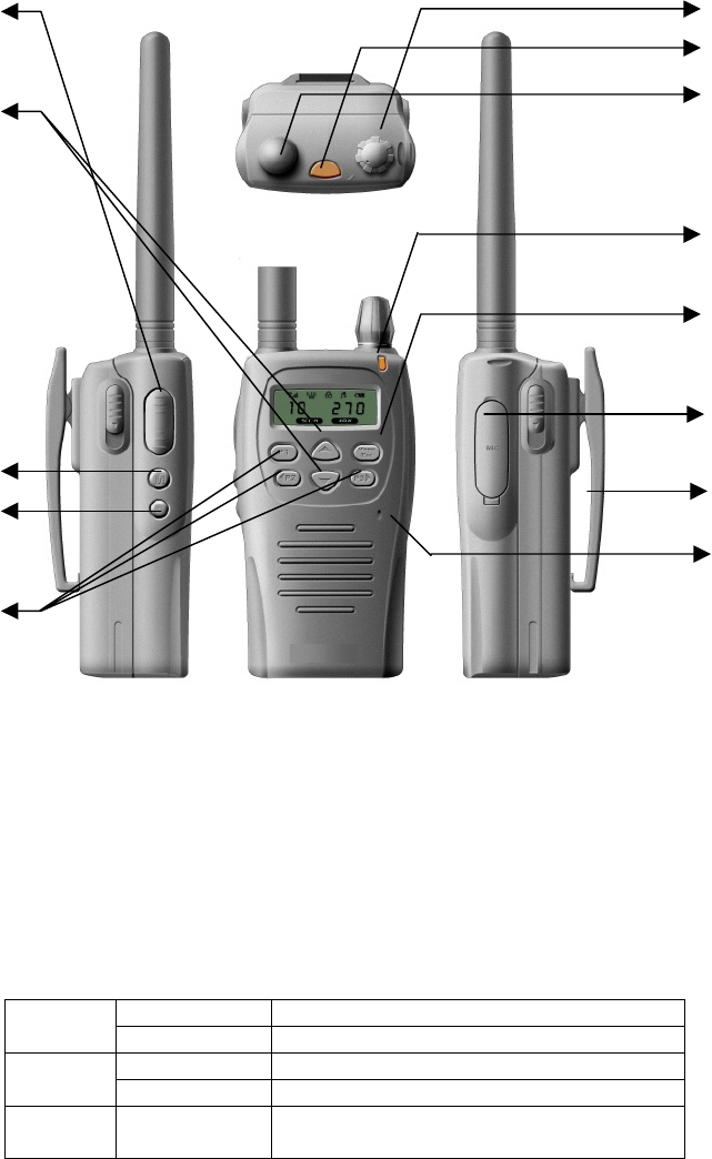
SPX Series Radio Controls
DESCRIPTION
1. Power switch / Use (Power) to: Turn power On/Off Adjust radio volume
2. Emergency button: Mode to enter Emergency Key
3. Antenna connector: Connect the supplied antenna here (SMA connector)
4. TX / RX / Battery Indicator
On Transmitting
Red Blinking Low battery
On Receiving, monitoring
Green Blinking Different sub-tone when receiving
Orange On Initializing, programming and
cloning
5. Menu button (Menu / Esc.)
6. Universal connector
Connect the external accessories (speaker / microphone, cloning cable & wall charger)
(optional)
7. Belt clip
8. MIC.
9
10
11
12
13
4
1
2
3
5
6
7
8
9. PTT (Push-to-Talk) Button
Hold down to transmit, release to receive.
10. Channel Select Button (Up & Down buttons)
Select the desired channel with pressing Up and Down button, pressing and holding down more than 1
second makes the channel moving fast
11. Monitor Button
Press to monitor. Holding down over 2 seconds keeps monitoring function on, and press shortly again or
PTT Button to stop.
12. Lamp
This key illuminates the LCD and keys on the front panel.
13. Programmable Keys
These keys may be programmed as “Hot Keys” for various features.
. .
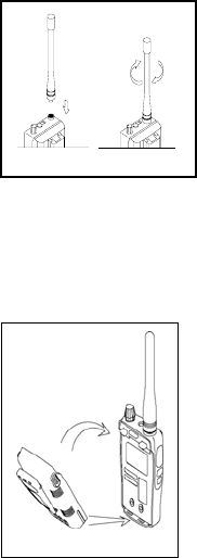
Installing Antenna:
z Place the antenna into the antenna connector on the top of left hand
side of the transceiver by holding the antenna at its base and turning
clockwise until secured.
Installing the Nickel-Metal Hydride Battery
Your radio is powered by a NiMH battery, which provides up to 8 hours of usage (based upon 5%
Transmit/ 5% Receive/ 90% Standby (standard duty cycle).
z Attach the battery matching the Ribbed Latch on the bottom of the radio.
z Position the battery by pushing the top back side of the battery.
z Securely snap the battery to the radio.
Charging with the charger
Charge the NiMH battery until the indication light turns green before using it for the first time, it will need
up to 3 hours to charge fully.
z Make sure the radio is off.
z Plug the charger into an electric outlet. The light on the charger will glow red to perform charging.
NOTE: If the radio is On while charging, additional time is required to charge the battery
z Use only the Charger supplied with the radio, or other SPX Series accessories.

Turning On/Off Your Radio
z Turn the knob on the top of the radio clockwise to turn the radio On. Turn the knob
counterclockwise to turn the radio Off.
z The radio beeps and the display briefly shows all features and display segments of your radio.
z The radio displays the current Channel and the Frequency assigned to that Channel or the
alpha-numeric name.
z You can set the volume by adjusting the knob on the top of the radio.
NOTE: Do not hold the radio too close to your ear when the volume is at a high setting.
z If the PASSWORD function is programmed, “PASSWORD” will display on the LCD when the
light power is turned on. To unlock the SPX Series, enter the correct password to activate.
z If the wrong password has been entered, “ERROR” will display on the LCD with radio remaining
locked with an error sound.
Volume Control
Rotate the Power On/Off Control Switch clockwise to increase the volume and counter clockwise to
reduce the volume. Rotate fully counter clockwise to turn transceiver off.
Operating Radio
To check Channel activity, press the monitor button: M. If you hear static, then the channel is clear
to use. Do not transmit if someone is speaking on the channel.
z Press and hold PTT and speak into the radio. To maximize clarity hold the radio 2 to 3
inches away from your mouth.
z To listen for messages, release PTT.
z The ICON will appear on the LCD. If the Busy Channel Lock Out (BCLO) function is
programmed, ”BC” will appears on the LCD with a alarm (--). If Time-Out-Timer function
is programmed, alarm () will be sound before 5 seconds of fixed time. After fixed
time, “TOT” will appears on the LCD and then, change to receiving mode.
NOTE: The transmit light on the front right of the radio flashes every three seconds when the radio
is On and is steady red when transmitting.
Signal Strength Indicator/Channel busy
The radio displays when there is activity on the channel and the transmit LED flashes every
second.
Receive
Choose the desired channel by pressing channel select button. The LED lights green when
receiving. If the signal doesn’t match the sub–tone programmed in your transceiver, the speaker will
be muted and the LED will flash green. The ICON will appear on the LCD.
Channel Select
Select the desired channel by pressing Up▲ and Down▼ scroll button. Pressing and holding down
more than 1 second will activate the channel to scroll faster with no sounds.
Key Lock On / Off
While holding the Menu Button, press P1 Button more than 3 seconds simultaneously to select the
key lock ON or OFF. The ICON appears on the LCD. This function prevents users from changing the
channel inadvertently.

User Programmable Features:
1. TX/RX Frequency
2. Select RX/TX Tone
3. 2-Tone Encode
User Program Mode
- To activate the Menu list for User Program Mode, you must press and hold the Menu/Esc button
while you turn on the radio.
- The up/down arrow buttons will allow you to select the desired channel, and the P2 and P3 buttons
will allow you to select the feature. The P1 button will be used to turn the feature On or Off, and the
Menu/Esc button will save the selection.
-Once all programming is complete, to exit User Program Mode, turn the radio off and then back on.
TX/RX Frequency List (Refer to Table 1):
1. The user will place radio in User Programming Mode as per previous instructions.
2. The user will select the "channel number" they wish to program using the Up/Down arrows.
3. The user will select “Frequency Table” using the P2 and P3 buttons. The feature will be selecte
d with the P1 button.
4 The user must will scroll through the list of frequencies with the 2 digit "code number" and "frequ
ency or alpha tag" displayed using the Up/Down arrows.
5. When the user selects a specific "code number" and enters the selection via the "menu/esc" key,
it will be assigned to the "channel number" (see step #2) the customer has selected.
6. When the user "exits" User programming mode, radio will only scroll through and display the num
ber of channels that the user has "programmed".
CTCSS/CDCSS Tones (Refer to Tables 2 and 3):
1. Once in User Program Mode, the channel number will be displayed.
2. The user will select a Channel Number with the Up/Down arrows, after 3 seconds the first feature of
the feature list will be displayed and the user can scroll through the feature list with the P2 or P3
buttons to find the CTCSS/CDCSS feature.
3. Once this feature is selected, pressing the P1 button will display the CTCSS/CDCSS list.
4. Using the Up/Down arrows the user can select a given code from the list.
5. Pressing the Menu/ESC button will save the selection for that Channel Number and bring the user
back to the feature list. The selected CTCSS/CDCSS code number will be used for both TX and RX
frequency.
2-Tone Encode:
1. Once in User Program Mode, the channel number will be displayed.
2. The user will select a Channel Number with the Up/Down arrows, after 3 seconds the first feature of
the feature list will be displayed and the user can scroll through the feature list with the P2 or P3
buttons to find 2-Tone Encode.
3. Once the feature is selected, pressing the P1 button will display the list, and using the Up/Down arrows
the user can select a given 2-Tone frequency pair from the list.
4. Pressing the Menu/ESC button will save the selection for that Channel Number and bring the user
back to the feature list.
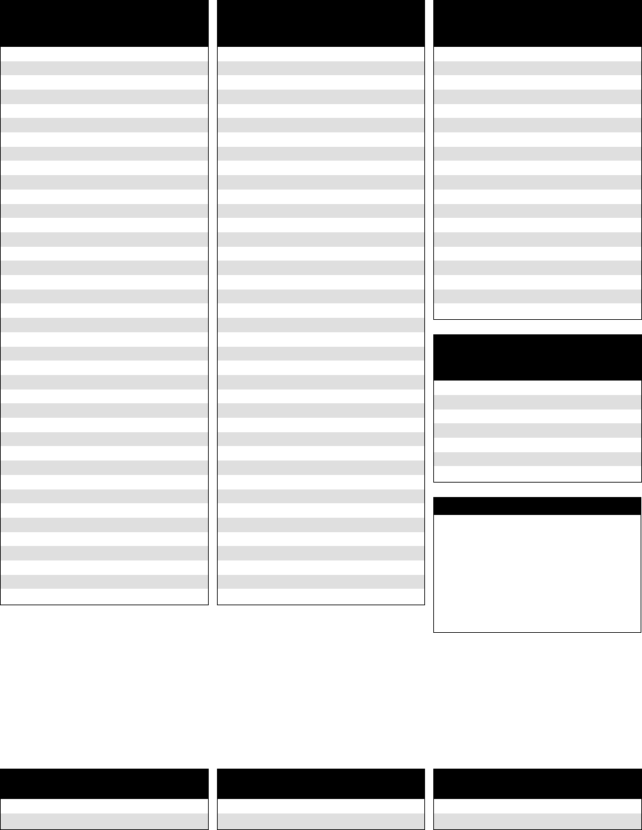
TABLE 1: PROGRAMMABLE FREQUENCY CODES...................
UHF Business Band
Code Frequency Color Dot BW
01 467.7625 J 25
02 467.8125 K 25
03 464.5500 Yellow Dot 25
04 464.5000 Brown Dot 25
05 467.8500 Silver Star 25
06 467.8750 Gold Star 25
07 467.9000 Red Star 25
08 467.9250 Blue Star 25
09 469.2625 25
10 462.5750 White Dot 25
11 462.6250 Black Dot 25
12 462.6750 Orange Dot 25
13 464.3250 25
14 464.8250 25
15 469.5000 25
16 469.5500 25
17 463.2625 25
18 464.9125 25
19 464.6000 25
20 464.7000 25
21 462.7250 25
22 464.5000 12.5
23 464.5500 12.5
24 467.7625 12.5
25 467.8125 12.5
26 467.8500 12.5
27 467.8750 12.5
28 467.9000 12.5
29 467.9250 12.5
30 461.0375 12.5
31 461.0625 12.5
32 461.0875 12.5
33 461.1125 12.5
34 461.1375 12.5
35 461.1625 12.5
36 461.1875 12.5
37 461.2125 12.5
38 461.2375 12.5
39 461.2625 12.5
UHF Business Band
Code Frequency Color Dot BW
40 461.2875 12.5
41 461.3125 12.5
42 461.3375 12.5
43 461.3625 12.5
44 462.7625 12.5
45 462.7875 12.5
46 462.8125 12.5
47 462.8375 12.5
48 462.8625 12.5
49 462.8875 12.5
50 462.9125 12.5
51 464.4875 12.5
52 464.5125 12.5
53 464.5375 12.5
54 464.5625 12.5
55 466.0375 12.5
56 466.0625 12.5
57 466.0875 12.5
58 466.1125 12.5
59 466.1375 12.5
60 466.1625 12.5
61 466.1875 12.5
62 466.2125 12.5
63 466.2375 12.5
64 466.2625 12.5
65 466.2875 12.5
66 466.3125 12.5
67 466.3375 12.5
68 466.3625 12.5
69 467.7875 12.5
70 467.8375 12.5
71 467.8625 12.5
72 467.8875 12.5
73 467.9125 12.5
74 469.4875 12.5
75 469.5125 12.5
76 469.5375 12.5
77 469.5625 12.5
VHF Business Band
Code Frequency Color Dot BW
03 151.625 Red Dot 25
04 151.955 Purple Dot 25
05 151.925 25
06 154.540 25
07 154.515 25
08 154.655 25
09 151.685 25
10 151.715 25
11 151.775 25
12 151.805 25
13 151.835 25
14 151.895 25
15 154.490 25
16 151.655 25
17 151.745 25
18 151.865 25
24 151.700 12.5
25 151.760 12.5
26 152.700 25
VHF MURS**
Code Frequency Color Dot BW
01 154.600 Green Dot 25
02 154.570 Blue Dot 25
19 151.820 MURS 12.5
20 151.880 MURS 12.5
21 151.940 MURS 12.5
22 154.600 MURS 12.5
23 154.570 MURS 12.5
Notes
** MURS frequencies do not
require an FCC license. All
other frequencies require an
FCC license.
• BW is the bandwidth in kHz.
• 12.5 kHz indicates a narrow
band channel, 25 kHz indicates
a wide band channel
CANADIAN FREQUENCY CODES ...........................................
Canada Models
UHF Business Band
Code Frequency Color Dot BW
01 458.6625 25
02 469.2625 25
Canada Models
VHF Business Band
Code Frequency Color Dot BW
01 151.055 25
02 151.115 25
British Columbia Models
VHF Business Band
Code Frequency Color Dot BW
01 154.100 25
02 158.940 25
TABLE 2: INTERFERENCE ELIMINATOR
PROGRAMMABLE QC TONE CODES......................................
Code Frequency
01 67.0
02 71.9
03 74.4
04 77.0
05 79.7
06 82.5
07 85.4
08 88.5
09 91.5
10 94.8
11 97.4
12 100.0
13 103.5
Code Frequency
14 107.2
15 110.9
16 114.8
17 118.8
18 123.0
19 127.3
20 131.8
21 136.5
22 141.3
23 146.2
24 151.4
25 156.7
26 162.2
Code Frequency
27 167.9
28 173.8
29 179.9
30 186.2
31 192.8
32 203.5
33 210.7
34 218.1
35 225.7
36 233.6
37 241.8
38 250.3
39 69.4
Code Frequency
40 159.8
41 165.5
42 171.3
43 177.3
44 No Tone
45 183.5
46 189.9
47 196.6
48 199.5
49 206.5
50 229.1
51 254.1
TABLE 3: DIGITAL INTERFERENCE ELIMINATOR
PROGRAMMABLE DQC TONE CODES.................................
Code
023
025
026
031
032
036
043
047
051
053
054
065
071
Code
072
073
074
114
115
116
122
125
131
132
134
143
145
Code
152
155
156
162
165
172
174
205
212
223
225
226
243
Code
244
245
246
251
252
255
261
263
265
266
271
274
306
Code
311
315
325
331
332
343
346
351
356
364
365
371
411
Code
412
413
423
431
432
445
446
452
454
455
462
464
465
Code
466
503
506
516
523
532
546
565
606
662
612
624
627
Code
631
632
645
654
664
703
712
723
731
732
734
743
754

Hot Keys
All Hot Key functions are PC programmable. All Hot Keys will have the option of “None” in their list of
options. The following is a list of functions that may be programmed for Hot Keys P1(short), P1(long),
P2(short), P2(long), P3(short0, and P3(long).
DTMF ANI – When the button is pressed momentarily (short) or for 3 seconds (long), the transmitter
will be activated and the DTMF digits that are programmed for that channel will be transmitted.
5 Tone ANI – When the button is pressed momentarily (short) or for 3 seconds (long), the transmitter
will be activated and the 5-Tone Code that is programmed for that channel will be transmitted.
Scan – When the button is pressed momentarily (short) or for 3 seconds (long), the unit will scan
according to the scan feature set-up. SCN icon will be displayed. To exit the scan feature, press
either Up/Down Channel Button. The SCN icon will not be displayed.
2-Tone Encode – When the button is pressed momentarily (short) or for 3 seconds (long), the
transmitter will be activated and the 2-Tone that is programmed for that channel will be
transmitted.
Weather Scan (VHF only) - When the button is pressed momentarily (short) or for 3 seconds (long),
the unit will scan the 7 U.S. weather frequencies. SCN icon will be displayed. If the unit stops
on the incorrect frequency, then a subsequent press will resume Weather Scan search for the
next active frequency in the list of 7 freqs. To exit the Weather Scan feature, press either
Up/Down Button. The SCN icon will not be displayed.
Key Lock – Pressing the button for Key Lock will disable all front panel buttons (including Menu/ESC
key) except for the button programmed for Key Lock. The lock icon will be displayed. Pressing
the button again will disable the function and the lock icon will not be displayed.
Talk Around – If using a repeater frequency, pressing the button for Talk Around will cause the radio to
transmit on the receive frequency when the PTT is pressed. The “T” icon will be displayed.
Pressing the button again will put the radio into normal operation and the “T” icon will not be
displayed.
TX Power – Pressing the button will alternately switch the power level from low to high power. “High
Power” or “Low Power” will be displayed momentarily. VHF: low power = 1 watt, high power = 5
watts, UHF: low power = 1 watt, high power = 4 watts.
None – A button that is programmed for “None” will have no effect when pressed.
PC Programmer
The following is a list of features that are PC programmable.
1. VOX
Internal Voice Operated Transmit allows you to operate in hands-free mode without pressing PTT.
When the VOX feature is enabled, the VOX ICON appears on LCD with “VOX LEVEL XX”. The
sensitivity level can be selected between 1(very sensitive) and 15 (less sensitive).
2. DTMF ANI
Once one of the “Hoy Keys” is selected for ANI operation, pressing that button will automatically
cause the radio to transmit the programmed ANI sequence up to XX characters.
3. 5-Tone ANI
Once one of the “Hoy Keys” is selected for 5-Tone ANI operation, pressing that button will
automatically cause the radio to transmit the programmed 5-Tone ANI sequence.
4. Scanning
Scan allows you to monitor other channels. When the radio detects activity, it stops scanning and
locks in on the active Channel. This allows you to talk and listen to the person transmitting without
changing channels.
Once one of the “Hoy Keys” is selected for SCAN operation, pressing that button will automatically
cause the radio to scan all channels programmed for scan.
Priority scan channel
One channel can be selected as a priority channel. When scanning or receiving, if there is
activity on the priority channel, the radio will automatically go to the priority channel until the
activity is finished.
5. TX power (1W or 4W/5W) per channel
TX output power can be to Low 1W or High 4W(UHF) or 5W(VHF). You can select low to extend
battery life or high to extend communication range.
6. Busy channel lockout
BCLO prevents users from transmitting if any activity is detected on the channel. If selected “BC” will
appear on the LCD.
7. Power Saving Control
If after a predetermined time the transceiver has not entered either transmit or receive mode, it will
automatically go into power save mode. This feature will further increase your duty cycle.
OFF: Power Saver is disabled
PSC-NORM: Normal mode
PSC-ENH: Enhance mode
8. Talk around
Once one of the “Hoy Keys” is selected for Talk-Around operation, pressing that button will
automatically cause the radio to transmit on the transmit frequency of the repeater system you are
using. A ”T” will appear on the LCD.
9. Squelch Level
You can program which levels you wish to set appropriate squelch level.
LEVEL 00: Loose, LEVEL 8: Standard, LEVEL 15: Tight
10. Large Font Display
Font size for the LCD can programmed or either “Small” or “Large”.
11. Select RX/TX Tone
QC, DQC, or NONE sub-audible sub-tones may be programmed for each channel.
12. Select RX/TX Frequency
Pre-selected table frequencies or custom RX and TX frequencies can be programmed for each
channel.
Additional Functions
1. LCD backlight
When you press Lamp button once, LCD backlight operates for 5 seconds
2. Low Battery Warning & Display
When the available capacity falls below 10%, the Battery ICON will flash with a warning sound. At
this time it is recommended that you either change or re-charge the battery pack as early as
possible. (Battery ICON indicates battery capacity)
3. Time–Out Timer (TOT)
This feature limits the amount of time you can continuously transmit on a channel. The time range
is programmable from 0~250 seconds. There will be a short pre–alert warning tone 4 seconds
prior to the end of the transmission, the transmission is then terminated and there will be a
constant alert tone until you release the PTT Button.

4. Cloning
You can clone data to other transceiver using the cloning cable.
To enter programming mode, While holding Monitor button, turn the Power switch at the same
time.
Use and Care
z Use a soft damp cloth to clean the exterior.
z Do not immerse in water.
z Do not use alcohol or cleaning solutions
SPECIFICATIONS
Model SPX-200 SPX-400
Frequency
Range
TX / RX
136-156MHz (L)
146-174MHz (H)
400-430MHz (L)
440-470MHz (H)
Dimension 110(H) x 50.5(W) x 37.5(D) mm
Weight (With Battery) 306g (0.71 lbs)
Operating Voltage DC 7.5V
Operating Temp. -30 ~ 60
Battery Life (5:5:90)
Hi power: 5 watts(VHF)
4 watts(UHF)
Low power: 1 watt
1350mAh Ni-MH : 8hrs
1350mAh Ni-MH : 11 hrs
Channels 128
Privacy Codes 38 QC, 83 DQC, INVERT 83 DQC
Band Width 12.5KHz /20 /25KHz programmable
Audio Power (16Ω) 500mW ((Min.) (5% Distortion)
z Specification is subject to change without prior notice
29roubleshooting
Troubleshooting Symptom Try This:
No Power
z Recharge or replace battery, reposition or replace
Message not transmitted
z Make sure PTT is completely pressed as you transmit.
z Recharge, replace and/or reposition batteries.
Limited talk range

z Steel and/or concrete structures, heavy foliage, buildings or vehicles decrease range. Check
for clear line of sight to improve transmission.
z Wearing radio close to body such as in a pocket or on a belt decreases range. Change
location of radio.
Message not received
z Confirm radios have the same Channel, Frequency, and QC/DQC tone.
z Recharge, replace and/or reposition batteries.
z Obstructions and operating indoors, or in vehicles, may interfere-- change location.
z Verify that the radio is not in Scan
Heavy static or interference
z Radios are too close, they must be at least five feet apart.
z Radios are too far apart or obstacles are interfering with transmission.
Low batteries
z Recharge or replace NiMH battery.
z Extreme operating temperatures affect battery life.
Charger light does not come on
z Check radio/battery is properly inserted and check battery/charger contacts to be sure they
are clean and charging pin is inserted correctly.
Symptom Try This:
Cannot activate VOX
z Feature not set and on. Sensitivity set to Level 1

RITRON,
INC.
L
IMITED
W
ARRANTY
........................................
WHAT THIS WARRANTY COVERS:
RITRON, INC. ("RITRON") provides the following warranty against defects in materials and/or workmanship in RITRON
Radios and Accessories under normal use and service during the applicable warranty period (as stated below). "Accessories"
means antennas, holsters, chargers, earphones, speaker/microphones and items contained in the programming and
programming/service kits.
WHAT IS COVERED FOR HOW LONG WHAT RITRON WILL DO
SPX Series Portable 1 year* During the first year after date of purchase,
RITRON will repair or replace the defective
product, at RITRON's option, parts and
labor included at no charge.
Accessories 90 days* *After date of purchase
WHAT THIS WARRANTY DOES NOT COVER:
• Any technical information provided with the covered product or any other RITRON products;
• Installation, maintenance or service of the product, unless this is covered by a separate written agreement with RITRON;
• Any products not furnished by RITRON which are attached or used with the covered product, or defects or damage from the
use of the covered product with equipment that is not covered (such as defects or damage from the charging or use of
batteries other than with covered product);
• Defects or damage, including broken antennas, resulting from:
- misuse, abuse, improper maintenance, alteration, modification, neglect, accident or act of God,
- the use of covered products other than in normal and customary manner or,
- improper testing or installation;
• Defects or damages from unauthorized disassembly, repair or modification, or where unauthorized disassembly, repair or
modification prevents inspection and testing necessary to validate warranty claims;
• Defects or damages in which the serial number has been removed, altered or defaced.
• Batteries if any of the seals are not intact.
IMPORTANT: This warranty sets forth the full extent of RITRON’s express responsibilities regarding the covered products, and
is given in lieu of all other express warranties. What RITRON has agreed to do above is your sole and exclusive remedy. No
person is authorized to make any other warranty to you on behalf of RITRON. Warranties implied by state law, such as implied
warranties of merchantability and fitness for a particular purpose, are limited to the duration of this limited warranty as it applies
to the covered product. Incidental and consequential damages are not recoverable under this warranty (this includes loss of use
or time, inconvenience, business interruption, commercial loss, lost profits or savings). Some states do not allow the exclusion
or limitation of incidental or consequential damages, or limitation on how long an implied warranty lasts, so the above limitations
or exclusions may not apply to you. Because each covered product system is unique, RITRON disclaims liability for range,

coverage, or operation of the system as a whole under this warranty.
WHO IS COVERED BY THIS WARRANTY: This warranty is given only to the purchaser or lessee of covered products
when acquired for use, not resale. This warranty is not assignable or transferable.
HOW TO GET WARRANTY SERVICE: To receive warranty service, you must deliver or send the defective product,
delivery costs and insurance prepaid, within the applicable warranty period, to RITRON, INC., 505 West Carmel Drive,
Carmel, Indiana 46032, Attention: Warranty Department. Please point out the nature of the defect in as much detail as
you can. You must retain your sales or lease receipt (or other written evidence of the date of purchase) and deliver it along with
the product. If RITRON chooses to repair or replace a defective product, RITRON may replace the product or any part or
component with reconditioned product, parts or components. Replacements are covered for the balance of the original
applicable warranty period. All replaced covered products, parts or components become RITRON’s property.
RIGHTS TO SOFTWARE RETAINED : Title and all rights or licenses to patents, copyrights, trademarks and trade
secrets in any RITRON software contained in covered products are and shall remain in RITRON. RITRON nevertheless grants
you a limited non-exclusive, transferable right to use the RITRON software only in conjunction with covered products. No other
license or right to the RITRON software is granted or permitted.
YOUR RIGHTS UNDER STATE LAW: This warranty gives you specific legal rights, and you may also have other rights
which vary from state to state.
Where This Warranty Is Valid: THIS WARRANTY IS VALID ONLY WITHIN THE UNITED STATES, THE DISTRICT OF
COLUMBIA AND PUERTO RICO.