Ritron RIT38-156 VHF-FM Callbox 2-Way Radio User Manual TABLE OF CONTENTS
Ritron Inc VHF-FM Callbox 2-Way Radio TABLE OF CONTENTS
UserManual.wiki
>
Ritron
>
RIT38 156 User Manual
Users Manual
Navigation menu
Upload a User Manual
Namespaces
Wiki Guide
HTML
PDF
Info
Views
User Manual
Discussion / Help
Navigation
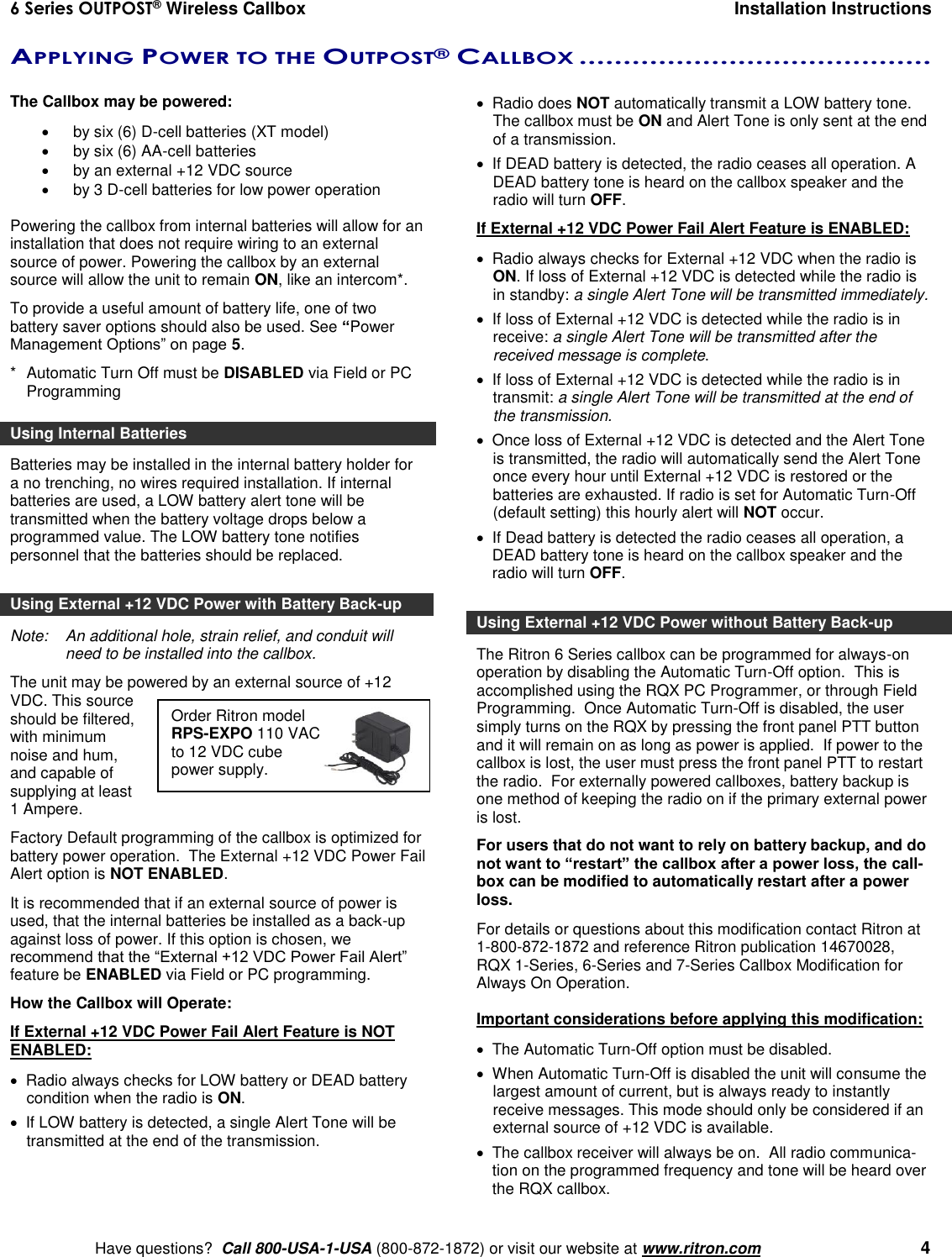
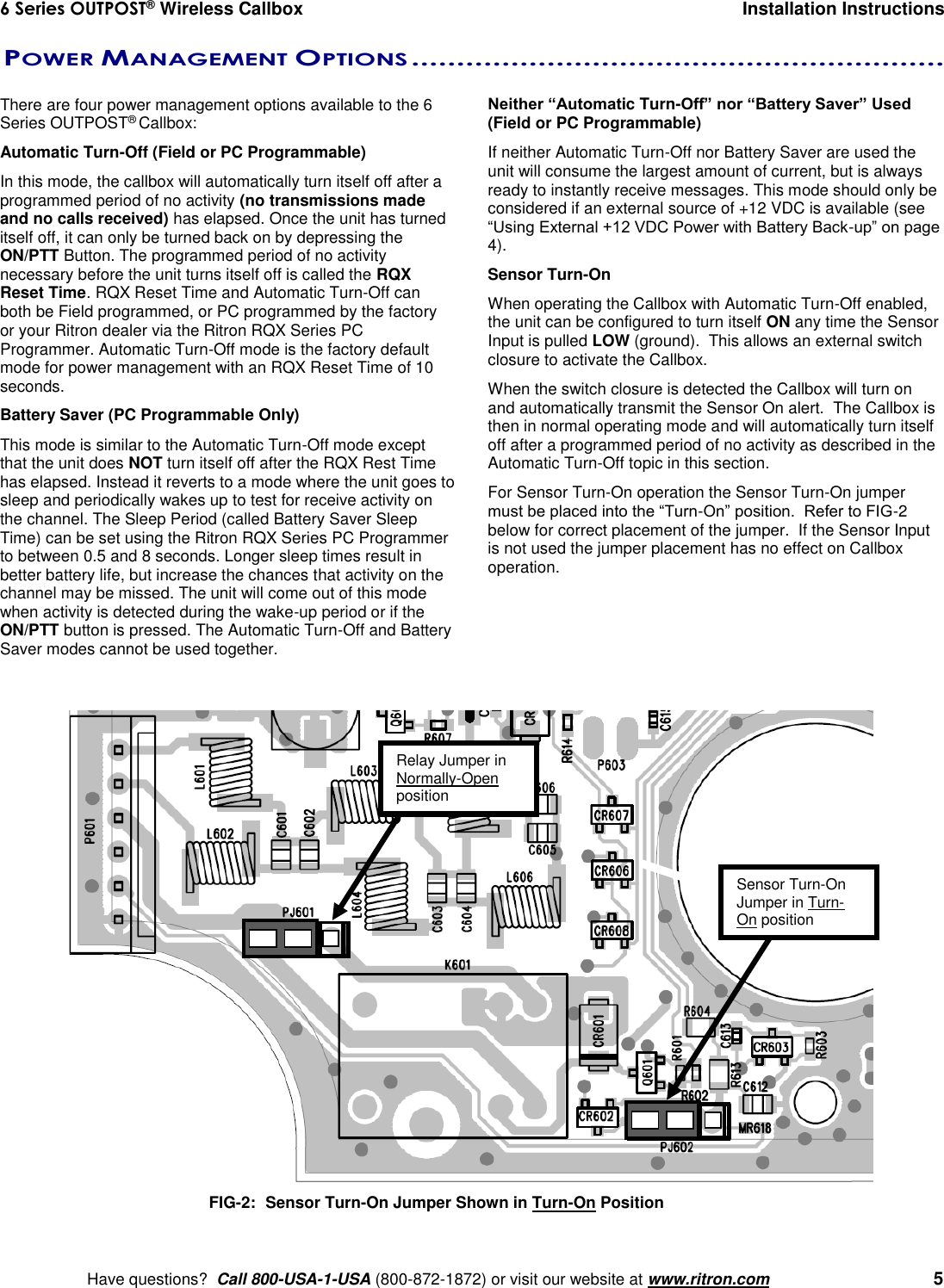
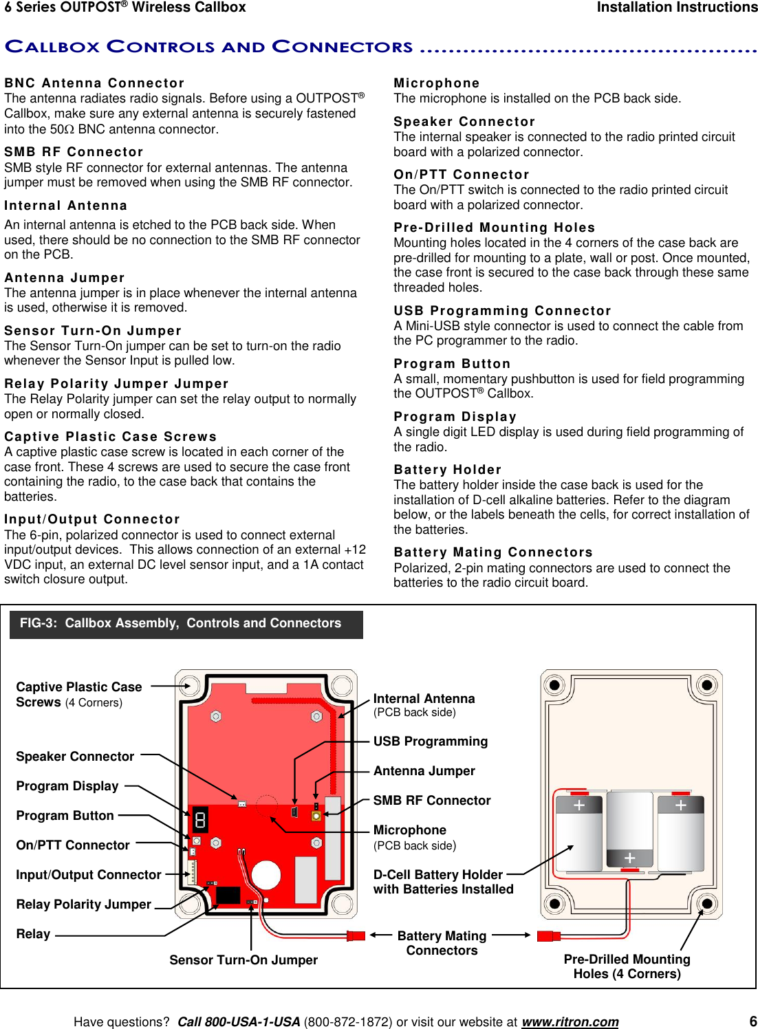
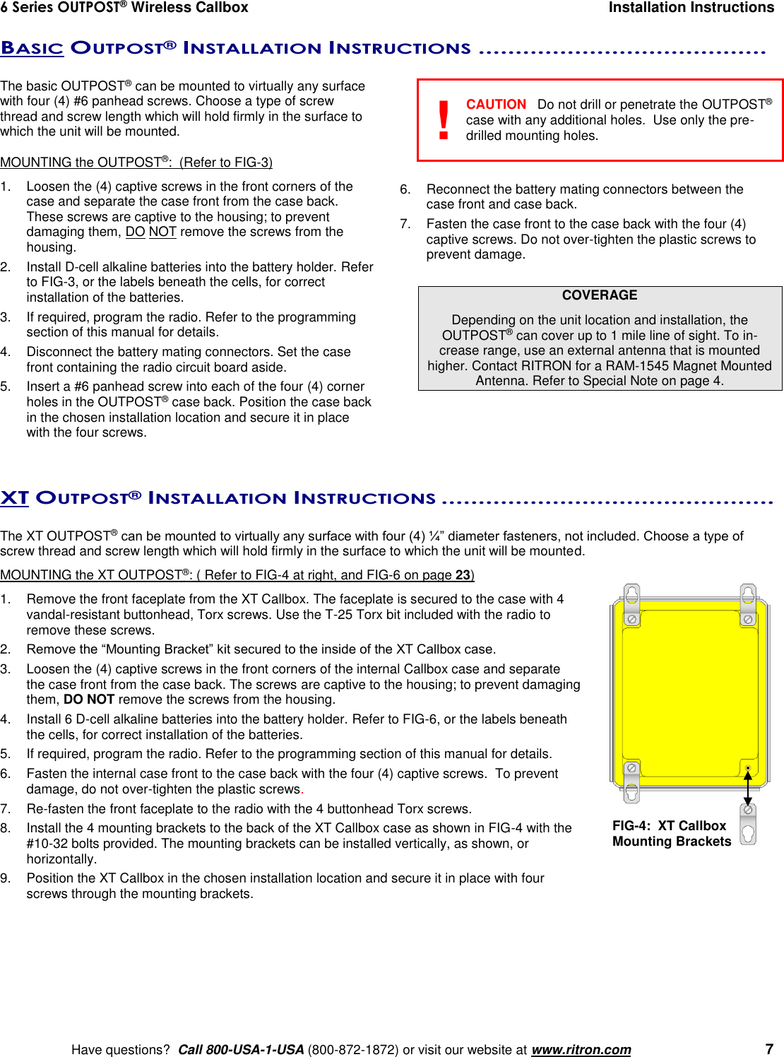
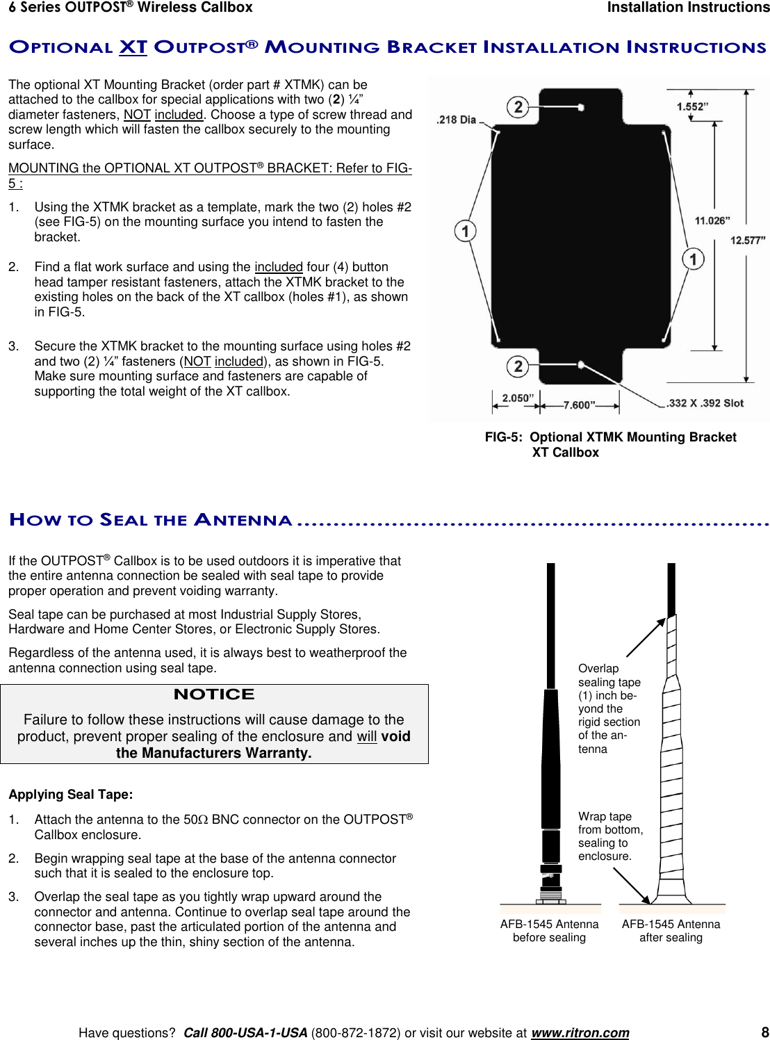
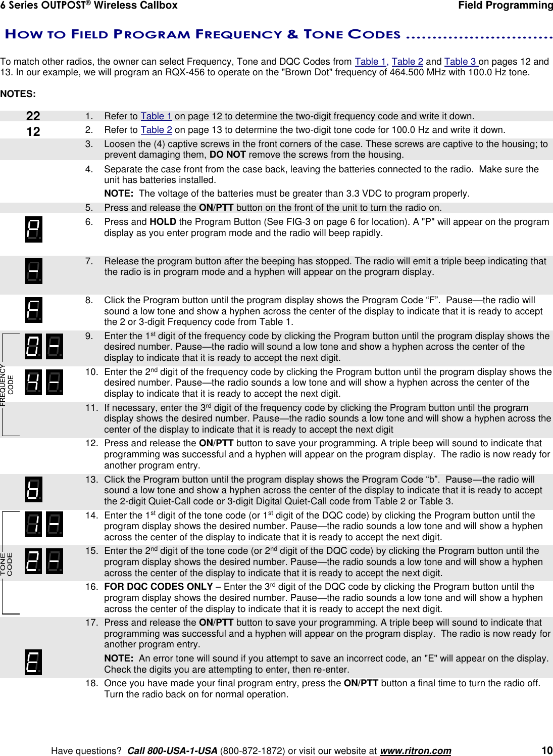
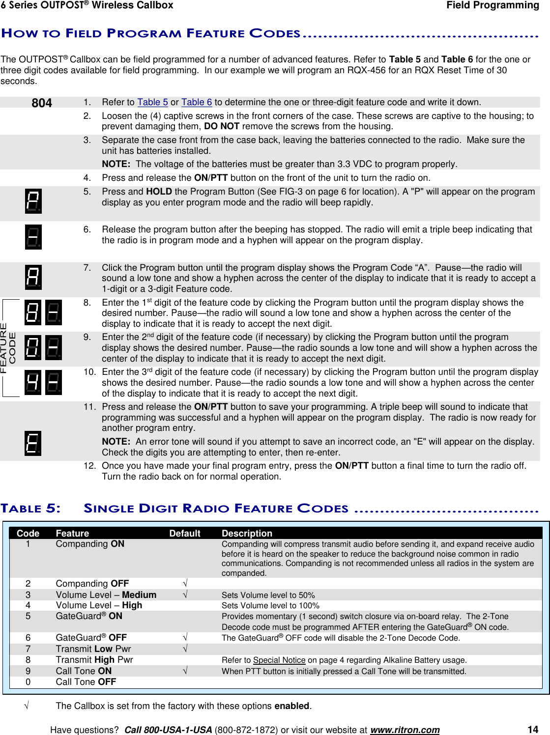
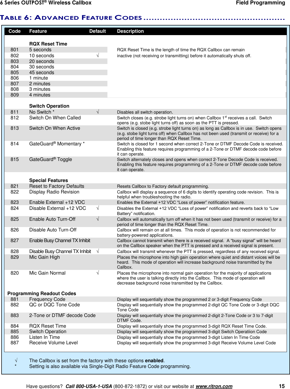
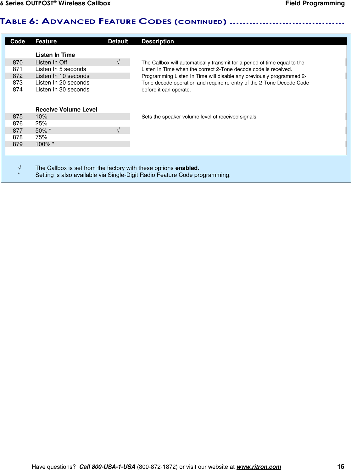
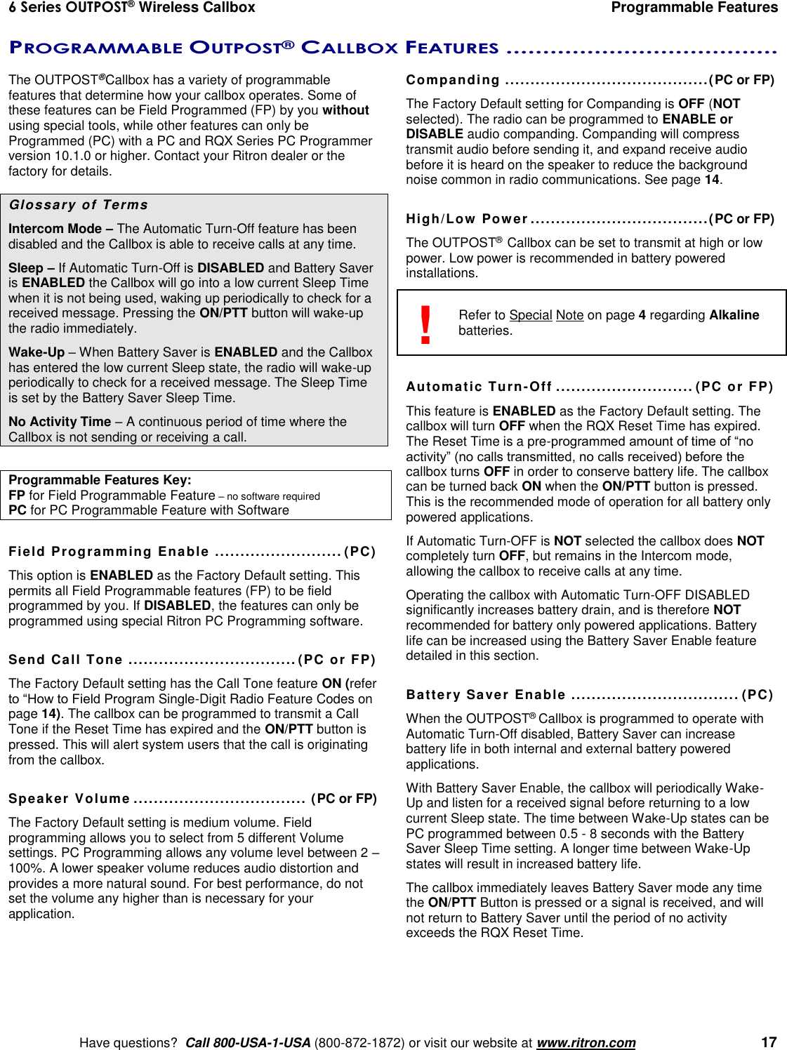
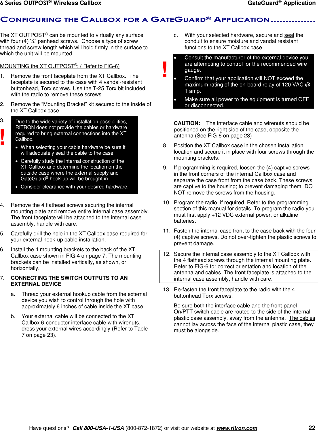
![6 Series OUTPOST® Wireless Callbox Field Programming Have questions? Call 800-USA-1-USA (800-872-1872) or visit our website at www.ritron.com 9 RQX FIELD PROGRAMMING OVERVIEW.................................................. Program Codes Table Codes Enter a 2-digit or 3-digit Frequency code from Table 1. Enter a 2-digit Quiet Call code from Table 2 or a 3-digit Digital Quiet Call code from Table 4. Enter a 2-digit, 2-Tone Paging code from Table 4 or Enter any 3 – 7-digit DTMF Code. Enter any 1-digit or 3-digit RQX Feature code from Tables 5 and 6 to: Enable or disable Companding. Enable or disable GateGuard® operation. Enable or disable Call Tone. Enable or disable External +12VDC operation. Enable or disable Automatic Turn-Off. Enable or disable Busy Channel TX Inhibit. Set microphone gain high or low. Set Listen In operation. Set RQX Reset Time. Set switch output operation. Reset RQX to Factory default programming. Enter the desired Speaker Volume Level as a 2–digit number from 05 – 99. Place the RQX Callbox into Program mode. Use PROGRAM button to scroll to one of the following Program Code characters: [F] [b] [C] [A] [U] Pause, a hyphen will appear on the display. Using the PROGRAM button, enter the desired Table Code. Press PTT button to save programming entry. Press PTT button a second time to Exit programming. or Proceed with next program entry.](https://usermanual.wiki/Ritron/RIT38-156/User-Guide-2365602-Page-11.png)