Riverbed Technology XR620 802.11ac 2x2 AP User Manual Xirrus AOS Xirrus
Xirrus, Inc. 802.11ac 2x2 AP Xirrus AOS Xirrus
Contents
User Manual

January 11, 2016
Release 7.6
Wireless Access Point
User’s Guide

All rights reserved. This document may not be reproduced or
disclosed in whole or in part by any means without the written
consent of Xirrus, Inc.
Part Number: 800-0022-001
(Revision T)
Wireless Access Points
XR and XD Series

Trademarks
is a registered trademark of Xirrus, Inc. All other trademarks and
brand names are marks of their respective holders.
Please see Legal Notices, Warnings, Compliance Statements, and Warranty and
License Agreements in “Notices (XR-1000 to XR-6000 Indoor Models)” on
page 561.
Xirrus, Inc.
2101 Corporate Center Drive
Thousand Oaks, CA 91320
USA
Tel: 1.805.262.1600
1.800.947.7871 Toll Free in the US
Fax: 1.866.462.3980
www.xirrus.com

Wireless Access Point
i
Table of Contents
List of Figures..................................................................................... xv
Introduction......................................................................................... 1
The Xirrus Family of Products ............................................................................... 1
Nomenclature .................................................................................................... 2
Why Choose the Xirrus Access Point? .................................................................. 3
Wireless Access Point Product Overview ............................................................ 4
XR Wireless AP Product Family ..................................................................... 5
XR-320 Wall Mounted 2-Radio Access Points ....................................... 5
XR-500 Series 2-Radio Access Points ...................................................... 6
XR-600 Series 2-Radio Access Points ...................................................... 7
XR-1000 Series 2-Radio Access Points .................................................... 8
XD4-130 4-Radio High Density Access Points ...................................... 9
XR-2006 Series 2- and 4-Radio High Density Access Points ............. 10
XR-2005 Series 2- and 4-Radio Access Points ...................................... 11
XR-4006 Series 4- to 8-Radio High Density Access Points ................. 12
XR-4000 Series 4- to 8-Radio High Density Access Points (not ending
in “6”) ................................................................................................. 13
XR-6000 Series 8- to 16-Radio High Density Access Points ............... 14
Enterprise Class Security ............................................................................... 14
Deployment Flexibility .................................................................................. 15
Power over Ethernet (POE) .................................................................... 16
Enterprise Class Management ...................................................................... 16
Key Features and Benefits ..................................................................................... 18
High Capacity and High Performance ........................................................ 18
Extended Coverage ......................................................................................... 18
Flexible Coverage Schemes .................................................................... 19
Non-Overlapping Channels .......................................................................... 20
SDMA Optimization ...................................................................................... 20
Fast Roaming ................................................................................................... 20
Ease of Deployment ........................................................................................ 20
Powerful Management ................................................................................... 20
Secure Wireless Access .................................................................................. 20

Wireless Access Point
ii
Applications Enablement .............................................................................. 21
Advanced Feature Sets .......................................................................................... 21
Xirrus Advanced RF Performance Manager (RPM) .................................. 21
Xirrus Advanced RF Security Manager (RSM) .......................................... 22
Xirrus Advanced RF Analysis Manager (RAM) ......................................... 23
Xirrus Application Control ............................................................................ 24
About this User’s Guide ........................................................................................ 25
Organization .................................................................................................... 25
Notes and Cautions ........................................................................................ 27
Screen Images .................................................................................................. 27
Product Specifications ........................................................................................... 27
Installing the Wireless AP............................................................... 29
Installation Prerequisites ...................................................................................... 29
Optional Network Components ................................................................... 31
Client Requirements ....................................................................................... 31
Planning Your Installation .................................................................................... 32
General Deployment Considerations .......................................................... 32
Coverage and Capacity Planning ................................................................. 34
Placement .................................................................................................. 34
RF Patterns ................................................................................................ 35
Capacity and Cell Sizes ........................................................................... 36
Fine Tuning Cell Sizes ............................................................................. 37
Roaming Considerations ........................................................................ 39
Allocating Channels ................................................................................ 39
Other Factors Affecting Throughput .................................................... 41
About IEEE 802.11ac ....................................................................................... 42
Up to Eight Simultaneous Data Streams — Spatial Multiplexing ..... 44
MIMO (Multiple-In Multiple-Out) ........................................................ 44
MU-MIMO (Multi-User Multiple-In Multiple-Out) ........................... 45
Higher Precision in the Physical Layer ................................................ 47
80 MHz and 160 MHz Channel Widths (Bonding) ............................ 48
802.11ac Data Rates ................................................................................. 49
ACExpress™ ............................................................................................ 50
802.11ac Deployment Considerations .......................................................... 50
Failover Planning ............................................................................................ 52
Switch Failover Protection ..................................................................... 54

Wireless Access Point
iii
Power Planning ............................................................................................... 55
Power over Ethernet ................................................................................ 55
Security Planning ........................................................................................... 56
Wireless Encryption ................................................................................ 56
Authentication ......................................................................................... 56
Meeting PCI DSS Standards ................................................................... 57
Meeting FIPS Standards ......................................................................... 57
Port Requirements .......................................................................................... 58
Network Management Planning .................................................................. 62
WDS Planning ................................................................................................. 63
Common Deployment Options .................................................................... 66
Installation Workflow ........................................................................................... 67
Installing Your Wireless AP ................................................................................. 69
Choosing a Location ....................................................................................... 69
Wiring Considerations ............................................................................ 69
Mounting and Connecting the AP .............................................................. 72
Dismounting the AP ....................................................................................... 72
Powering Up the Wireless AP .............................................................................. 72
AP LED Operating Sequences ...................................................................... 73
LED Boot Sequence ................................................................................. 73
LED Operation when AP is Running ................................................... 74
Zero-Touch Provisioning and Ongoing Management .................................... 75
XMS-Cloud Next Generation (XMS-9500-CL-x) ................................. 75
XMS-Enterprise ........................................................................................ 75
If you are not using XMS ........................................................................ 76
AP Management Interfaces .................................................................................. 76
User Interfaces ................................................................................................. 76
Using the Serial Port ....................................................................................... 78
Using the Ethernet Ports to Access the AP ................................................. 78
Starting the WMI ............................................................................................. 79
Logging In ........................................................................................................ 79
Licensing ................................................................................................................. 80
Performing the Express Setup Procedure ........................................................... 80
Securing Low Level Access to the AP .......................................................... 81
The Web Management Interface................................................... 85
Managing APs Locally or Using XMS ................................................................ 85

Wireless Access Point
iv
An Overview .......................................................................................................... 86
Structure of the WMI ............................................................................................. 87
User Interface ......................................................................................................... 89
Logging In ............................................................................................................... 92
Applying Configuration Changes ....................................................................... 93
Character Restrictions .................................................................................... 93
Viewing Status on the Wireless AP................................................ 95
Access Point Status Windows .............................................................................. 96
Access Point Summary ................................................................................... 96
Content of the Access Point Summary Window ................................. 97
Access Point Information ............................................................................. 102
Access Point Configuration ......................................................................... 103
Admin History .............................................................................................. 104
Network Status Windows ................................................................................... 104
Network ......................................................................................................... 105
Network Map ................................................................................................ 106
Content of the Network Map Window .............................................. 106
Spanning Tree Status .................................................................................... 109
Routing Table ................................................................................................ 110
ARP Table ...................................................................................................... 110
DHCP Leases ................................................................................................. 111
Connection Tracking/NAT ......................................................................... 111
CDP List ......................................................................................................... 112
LLDP List ....................................................................................................... 113
Network Assurance ...................................................................................... 113
Undefined VLANs ........................................................................................ 114
RF Monitor Windows .......................................................................................... 115
IAP Monitoring ............................................................................................. 116
Spectrum Analyzer .................................................................................... 117
Rogues ........................................................................................................... 120
Channel History ............................................................................................ 122
Radio Assurance ........................................................................................... 124
Station Status Windows ...................................................................................... 126
Stations ........................................................................................................... 127
Location Map ................................................................................................. 129
RSSI ................................................................................................................. 132

Wireless Access Point
v
Signal-to-Noise Ratio (SNR) ........................................................................ 134
Noise Floor ..................................................................................................... 135
Max by IAP .................................................................................................... 137
Station Assurance ......................................................................................... 138
Statistics Windows ............................................................................................... 139
IAP Statistics Summary ................................................................................ 139
Per-IAP Statistics ........................................................................................... 140
Network Statistics ......................................................................................... 142
VLAN Statistics ............................................................................................. 143
WDS Statistics ................................................................................................ 144
IDS Statistics .................................................................................................. 145
Filter Statistics ............................................................................................... 147
Station Statistics ............................................................................................ 147
Per-Station Statistics ..................................................................................... 149
Application Control Windows ........................................................................... 150
About Application Control ......................................................................... 150
Application Control ...................................................................................... 152
Stations (Application Control) .................................................................... 156
System Log Window ........................................................................................... 157
IDS Event Log Window ...................................................................................... 158
Configuring the Wireless AP........................................................ 161
Express Setup ........................................................................................................ 163
Network ................................................................................................................. 169
Interfaces ....................................................................................................... 170
Network Interface Ports ........................................................................ 171
Bonds and Bridging ...................................................................................... 173
DNS Settings .................................................................................................. 180
Cisco Discovery Protocol (CDP) Settings .................................................. 181
LLDP Settings ................................................................................................ 182
Services .................................................................................................................. 185
Time Settings (NTP) ..................................................................................... 186
NetFlow .......................................................................................................... 189
Wi-Fi Tag ....................................................................................................... 190
Location .......................................................................................................... 191
System Log ..................................................................................................... 193
About Using Splunk for Xirrus APs ................................................... 196

Wireless Access Point
vi
SNMP .............................................................................................................. 197
DHCP Server ................................................................................................. 200
Proxy Services ............................................................................................... 202
About Proxy Forwarding ..................................................................... 203
Proxy Forwarding for HTTPS .............................................................. 204
Summary of Proxy Forwarding Behavior on the AP ....................... 205
About Using a Proxy Client for Management Traffic ...................... 210
VLANs ................................................................................................................... 213
Understanding Virtual Tunnels .......................................................... 214
VLAN Pools ............................................................................................ 215
VLAN Management ..................................................................................... 216
Tunnels .................................................................................................................. 220
About Xirrus Tunnels ........................................................................... 220
Tunnel Management .................................................................................... 221
SSID Assignments ......................................................................................... 223
VLAN Assignments ...................................................................................... 224
Security .................................................................................................................. 225
Understanding Security ........................................................................ 226
Certificates and Connecting Securely to the WMI ............................ 229
Using the AP’s Default Certificate ...................................................... 230
Using an External Certificate Authority ............................................. 231
Admin Management .................................................................................... 231
Admin Privileges .......................................................................................... 233
Admin RADIUS ............................................................................................ 235
About Creating Admin Accounts on the RADIUS Server ............. 235
Management Control ................................................................................... 238
Access Control List ....................................................................................... 248
Global Settings .............................................................................................. 250
External Radius ............................................................................................. 254
About Creating User Accounts on the RADIUS Server .................. 255
Internal Radius .............................................................................................. 258
Active Directory ............................................................................................ 260
Rogue Control List ........................................................................................ 264
OAuth 2.0 Management ............................................................................... 265
SSIDs ...................................................................................................................... 268
Understanding SSIDs ............................................................................ 269
Understanding QoS Priority on the Wireless AP ............................. 271

Wireless Access Point
vii
High Density 2.4G Enhancement—Honeypot SSID ......................... 275
SSID Management ........................................................................................ 277
SSID List (top of page) .......................................................................... 278
SSID Limits and Scheduling ................................................................ 284
Web Page Redirect (Captive Portal) Configuration ........................ 287
Whitelist Configuration for Web Page Redirect .............................. 293
Web Page Redirect for Purple WiFi Venues ..................................... 294
WPA Configuration .............................................................................. 297
Authentication Service Configuration ............................................... 297
Active IAPs .................................................................................................... 298
Per-SSID Access Control List ...................................................................... 299
Honeypots ...................................................................................................... 300
Personal Wi-Fi ............................................................................................... 302
Groups ................................................................................................................... 304
Understanding Groups ......................................................................... 304
Using Groups ......................................................................................... 305
Group Management ..................................................................................... 306
Group Limits .......................................................................................... 309
IAPs ........................................................................................................................ 311
Understanding Fast Roaming .............................................................. 312
IAP Settings ................................................................................................... 313
Global Settings ............................................................................................. 319
Beacon Configuration ........................................................................... 321
Station Management ............................................................................. 322
Advanced Traffic Optimization .......................................................... 324
Global Settings .11an .................................................................................... 335
Global Settings .11bgn .................................................................................. 341
Global Settings .11n ...................................................................................... 347
Global Settings .11ac ..................................................................................... 350
Global Settings .11u ...................................................................................... 352
Understanding 802.11u ......................................................................... 352
Advanced RF Settings .................................................................................. 358
About Standby Mode ............................................................................ 358
RF Monitor .............................................................................................. 359
RF Resilience .......................................................................................... 360
RF Power and Sensitivity ..................................................................... 361
RF Spectrum Management ................................................................... 362

Wireless Access Point
viii
Station Assurance .................................................................................. 365
Hotspot 2.0 ..................................................................................................... 367
Understanding Hotspot 2.0 .................................................................. 367
NAI Realms .................................................................................................... 370
Understanding NAI Realm Authentication ....................................... 370
NAI EAP ......................................................................................................... 371
Intrusion Detection ....................................................................................... 373
DoS Attacks ............................................................................................ 374
Impersonation Attacks .......................................................................... 375
About Blocking Rogue APs .................................................................. 376
RF Intrusion Detection and Auto Block Mode .................................. 377
DoS Attack Detection Settings ............................................................. 379
Impersonation Detection Settings ....................................................... 379
LED Settings .................................................................................................. 380
DSCP Mappings ............................................................................................ 381
Roaming Assist .............................................................................................. 382
WDS ....................................................................................................................... 385
About Configuring WDS Links .................................................................. 385
Long Distance Links ..................................................................................... 387
WDS Client Links ......................................................................................... 387
Filters ..................................................................................................................... 391
Filter Lists ...................................................................................................... 392
Filter Management ....................................................................................... 395
Clusters .................................................................................................................. 401
Cluster Management ................................................................................... 401
Mobile .................................................................................................................... 406
AirWatch ........................................................................................................ 406
User Procedure for Wireless Access ................................................... 408
Using Tools on the Wireless AP................................................... 411
System Tools ......................................................................................................... 412
About Licensing and Upgrades ........................................................... 412
System ..................................................................................................... 414
Remote Boot Services ............................................................................ 416
Configuration Management ................................................................. 417
Diagnostics ............................................................................................. 421
Application Control Signature File Management ............................. 422

Wireless Access Point
ix
Web Page Redirect (Captive Portal) ................................................... 423
Network Tools ........................................................................................ 424
Progress Bar and Status Frame ............................................................ 426
CLI ......................................................................................................................... 426
API Documentation ............................................................................................. 428
Status/Settings ....................................................................................... 429
GET Requests ......................................................................................... 429
Trying a GET Request ........................................................................... 430
API Documentation Toolbar ................................................................ 432
Options .................................................................................................................. 433
Logout .................................................................................................................... 434
The Command Line Interface...................................................... 435
Establishing a Secure Shell (SSH) Connection ................................................. 435
Getting Started with the CLI .............................................................................. 437
Entering Commands .................................................................................... 437
Getting Help .................................................................................................. 437
Top Level Commands ......................................................................................... 440
Root Command Prompt ............................................................................... 440
configure Commands ................................................................................... 441
show Commands .......................................................................................... 445
statistics Commands ..................................................................................... 450
Configuration Commands .................................................................................. 452
acl .................................................................................................................... 452
admin .............................................................................................................. 453
auth ................................................................................................................. 454
cdp ................................................................................................................... 454
clear ................................................................................................................. 456
cluster ............................................................................................................. 458
contact-info .................................................................................................... 459
date-time ........................................................................................................ 460
dhcp-server .................................................................................................... 461
dns ................................................................................................................... 462
file .................................................................................................................... 463
filter ................................................................................................................. 467
Air Cleaner ............................................................................................. 468
group .............................................................................................................. 471

Wireless Access Point
x
hostname ........................................................................................................ 471
interface .......................................................................................................... 472
load ................................................................................................................. 473
location ........................................................................................................... 473
location-reporting ......................................................................................... 474
management .................................................................................................. 475
mdm ................................................................................................................ 477
more ................................................................................................................ 478
netflow ............................................................................................................ 479
no ..................................................................................................................... 480
quick-config ................................................................................................... 481
quit .................................................................................................................. 482
authentication-server ................................................................................... 482
reboot .............................................................................................................. 484
reset ................................................................................................................. 484
restore ............................................................................................................. 485
roaming-assist ............................................................................................... 486
run-tests .......................................................................................................... 487
security ........................................................................................................... 489
snmp ............................................................................................................... 490
ssid .................................................................................................................. 491
syslog .............................................................................................................. 492
tunnel .............................................................................................................. 493
uptime ............................................................................................................. 494
vlan .................................................................................................................. 494
wifi-tag ........................................................................................................... 495
Sample Configuration Tasks .............................................................................. 497
Configuring a Simple Open Global SSID .................................................. 498
Configuring a Global SSID using WPA-PEAP ......................................... 499
Configuring an SSID-Specific SSID using WPA-PEAP ........................... 500
Enabling Global IAPs ................................................................................... 501
Disabling Global IAPs .................................................................................. 502
Enabling a Specific IAP ................................................................................ 503
Disabling a Specific IAP ............................................................................... 504
Setting Cell Size Auto-Configuration for All IAPs .................................. 505
Setting the Cell Size for All IAPs ................................................................ 506
Setting the Cell Size for a Specific IAP ....................................................... 507

Wireless Access Point
xi
Configuring VLANs on an Open SSID ...................................................... 508
Configuring Radio Assurance Mode (Loopback Tests) .......................... 509
Appendices..................................................................................... 511
Appendix A: Quick Reference Guide ...........................................513
Factory Default Settings ...................................................................................... 513
Host Name ..................................................................................................... 513
Network Interfaces ....................................................................................... 513
Serial ........................................................................................................ 513
Gigabit 1 and Gigabit 2 ......................................................................... 514
Server Settings ............................................................................................... 514
NTP .......................................................................................................... 514
Syslog ...................................................................................................... 514
SNMP ...................................................................................................... 515
DHCP .............................................................................................................. 515
Default SSID .................................................................................................. 516
Security .......................................................................................................... 516
Global Settings - Encryption ............................................................... 516
External RADIUS (Global) .................................................................. 517
Internal RADIUS .................................................................................... 518
Administrator Account and Password ...................................................... 518
Management .................................................................................................. 518
Keyboard Shortcuts ............................................................................................. 519
Appendix B: FAQ and Special Topics ..........................................521
General Hints and Tips ....................................................................................... 521
Frequently Asked Questions .............................................................................. 522
Multiple SSIDs ............................................................................................... 522
Security ........................................................................................................... 524
VLAN Support .............................................................................................. 527
AP Monitor and Radio Assurance Capabilities ............................................... 529
Enabling Monitoring on the AP .......................................................... 529
How Monitoring Works ............................................................................... 529
Radio Assurance ........................................................................................... 530
Radio Assurance Options ..................................................................... 531
RADIUS Vendor Specific Attribute (VSA) for Xirrus ..................................... 532
Location Service Data Formats .......................................................................... 533

Wireless Access Point
xii
Euclid Location Server ................................................................................. 533
Non-Euclid Location Server ........................................................................ 533
Upgrading the AP Using the Boot Loader ....................................................... 537
Sample Output for the Upgrade Procedure: ............................................. 539
Appendix C: Notices (XD and XR500/600 Series Only) ..........543
Notices ................................................................................................................... 543
EU Directive 1999/5/EC Compliance Information ........................................ 549
Compliance Information (Non-EU) ................................................................... 556
Safety Warnings ................................................................................................... 557
Translated Safety Warnings ............................................................................... 558
Software License and Product Warranty Agreement ..................................... 559
Hardware Warranty Agreement ....................................................................... 559
Appendix D: Notices (XR-1000 to XR-6000 Indoor Models) ...561
Notices ................................................................................................................... 561
EU Directive 1999/5/EC Compliance Information ........................................ 566
Compliance Information (Non-EU) ................................................................... 573
Safety Warnings ................................................................................................... 575
Translated Safety Warnings ............................................................................... 576
Software License and Product Warranty Agreement ..................................... 578
Hardware Warranty Agreement ....................................................................... 578
Appendix E: Medical Usage Notices ...........................................579
Appendix F: Auditing PCI DSS ....................................................585
Payment Card Industry Data Security Standard Overview .......................... 585
PCI DSS and Wireless .......................................................................................... 586
The Xirrus AP PCI Compliance Configuration ............................................... 587
The pci-audit Command ..................................................................................... 588
Additional Resources .......................................................................................... 589
Appendix G: Implementing FIPS Security ..................................591
Securing the AP Physically ................................................................................. 591
Operator Required Actions .................................................................. 591
Applying Tamper Evident Seals ......................................................... 592
To implement FIPS 140-2, Level 2 using WMI ................................................. 593
To implement FIPS 140-2, Level 2 using CLI: .................................................. 596
To check if AP is in FIPS mode: ......................................................................... 596

Wireless Access Point
xiii
About FIPS Configuration .................................................................................. 597
Glossary of Terms.......................................................................... 599
Index................................................................................................ 611

Wireless Access Point
xiv

Wireless Access Point
List of Figures xv
List of Figures
Figure 1. Xirrus AP ..................................................................................................... 1
Figure 2. Wireless AP (XR Series) ............................................................................ 4
Figure 3. Wireless Coverage Patterns .................................................................... 15
Figure 4. XP8 - Power over Ethernet Usage .......................................................... 16
Figure 5. WMI: AP Status......................................................................................... 17
Figure 6. Layout of IAPs (XR-7630)........................................................................ 18
Figure 7. Coverage Schemes (XR-7230 shown)..................................................... 19
Figure 8. Wall Thickness Considerations .............................................................. 33
Figure 9. Unit Placement.......................................................................................... 34
Figure 10. Full (Normal) Coverage........................................................................... 35
Figure 11. Adjusting RF Patterns.............................................................................. 35
Figure 12. Custom Coverage ..................................................................................... 36
Figure 13. Connection Rate vs. Distance.................................................................. 36
Figure 14. Transmit Power......................................................................................... 37
Figure 15. Auto Cell Size Options............................................................................. 38
Figure 16. Overlapping Cells..................................................................................... 39
Figure 17. Allocating Channels Manually............................................................... 40
Figure 18. Spatial Multiplexing................................................................................. 44
Figure 19. MIMO Signal Processing......................................................................... 45
Figure 20. MU-MIMO with Four Antennas ............................................................ 46
Figure 21. Physical Layer Data Encoding................................................................ 47
Figure 22. Channel Bonding (Channels 36-64 shown)........................................... 49
Figure 23. Maximum 802.11ac Data Rates............................................................... 49
Figure 24. Port Failover Protection........................................................................... 52
Figure 25. Switch Failover Protection ..................................................................... 54
Figure 26. Port Requirements for XMS .................................................................... 58
Figure 27. WDS Link................................................................................................... 63
Figure 28. A Multiple Hop WDS Connection ......................................................... 64
Figure 29. WDS Failover Protection ......................................................................... 64
Figure 30. Installation Workflow .............................................................................. 67
Figure 31. AP Placement ............................................................................................ 69
Figure 32. LED Locations........................................................................................... 72
Figure 33. Network Interface Ports—XR-520 (left); XR-1000 Series (right) ........ 76
Figure 34. Network Interface Ports—XR-600 Series ............................................. 77

Wireless Access Point
xvi List of Figures
Figure 35. Network Interfaces—XR-2000 Series (left); XR-2005/2006 (right) .... 77
Figure 36. Network Interface Ports—XR-4000 Series ............................................ 77
Figure 37. Network Interface Ports—XR-6000 Series ............................................ 77
Figure 38. Web Management Interface .................................................................... 86
Figure 39. WMI: Frames............................................................................................. 89
Figure 40. WMI Header.............................................................................................. 90
Figure 41. WMI Command Log ................................................................................ 91
Figure 42. WMI: Utility Buttons................................................................................ 91
Figure 43. Logging In to the Wireless AP................................................................ 92
Figure 44. AP Summary ............................................................................................. 96
Figure 45. Disabled IAP (Partial View).................................................................... 99
Figure 46. IAP Cells .................................................................................................... 99
Figure 47. Network Assurance and Operating Status......................................... 100
Figure 48. AP Information ....................................................................................... 102
Figure 49. Show Configuration ............................................................................... 103
Figure 50. Admin Login History............................................................................. 104
Figure 51. Network Settings .................................................................................... 105
Figure 52. Network Map.......................................................................................... 106
Figure 53. Spanning Tree Status.............................................................................. 109
Figure 54. Routing Table.......................................................................................... 110
Figure 55. ARP Table ................................................................................................ 110
Figure 56. DHCP Leases........................................................................................... 111
Figure 57. Connection Tracking.............................................................................. 111
Figure 58. CDP List ................................................................................................... 112
Figure 59. LLDP List................................................................................................. 113
Figure 60. Network Assurance................................................................................ 113
Figure 61. Undefined VLANs.................................................................................. 114
Figure 62. RF Monitor — IAPs ................................................................................. 116
Figure 63. RF Monitor — IAPs ................................................................................. 116
Figure 64. RF Spectrum Analyzer........................................................................... 118
Figure 65. Intrusion Detection/Rogue AP List..................................................... 120
Figure 66. RF Monitor — Channel History............................................................. 122
Figure 67. RF Monitor — Channel History (Rotated) ........................................... 123
Figure 68. RF Monitor — Channel History (Text) ................................................. 123
Figure 69. Radio Assurance..................................................................................... 124
Figure 70. Stations..................................................................................................... 127
Figure 71. Location Map........................................................................................... 129

Wireless Access Point
List of Figures xvii
Figure 72. Controls for Location Map .................................................................... 130
Figure 73. Station RSSI Values ................................................................................ 132
Figure 74. Station RSSI Values — Colorized Graphical View ............................. 133
Figure 75. Station Signal-to-Noise Ratio Values................................................... 134
Figure 76. Station SNR Values — Colorized Graphical View.............................. 134
Figure 77. Station Noise Floor Values.................................................................... 135
Figure 78. Station Noise Floor Values — Colorized Graphical View................. 136
Figure 79. Max by IAP.............................................................................................. 137
Figure 80. Station Assurance ................................................................................... 138
Figure 81. IAP Statistics Summary Page................................................................ 139
Figure 82. Individual IAP Statistics Page .............................................................. 141
Figure 83. Network Statistics................................................................................... 142
Figure 84. VLAN Statistics....................................................................................... 143
Figure 85. WDS Statistics ......................................................................................... 144
Figure 86. IDS Statistics Page .................................................................................. 145
Figure 87. Filtered IDS Statistics ............................................................................. 146
Figure 88. Filter Statistics ......................................................................................... 147
Figure 89. Station Statistics ...................................................................................... 147
Figure 90. Individual Station Statistics Page......................................................... 149
Figure 91. Application Control ............................................................................... 152
Figure 92. Application Control (Pie Charts).......................................................... 154
Figure 93. Application Control (Station Traffic)................................................... 155
Figure 94. Stations (Application Control).............................................................. 156
Figure 95. System Log (Alert Level Highlighted) ................................................ 157
Figure 96. IDS Event Log ......................................................................................... 158
Figure 97. WMI: Express Setup............................................................................... 163
Figure 98. LEDs are Switched On........................................................................... 168
Figure 99. Network Interfaces................................................................................. 169
Figure 100. Network Settings .................................................................................... 170
Figure 101. Network Bonds and Bridging............................................................... 173
Figure 102. Bridging Traffic....................................................................................... 174
Figure 103. Port Modes (a, b)..................................................................................... 176
Figure 104. Port Modes (c, d)..................................................................................... 177
Figure 105. Mirroring Traffic..................................................................................... 179
Figure 106. DNS Settings............................................................................................ 180
Figure 107. CDP Settings............................................................................................ 181
Figure 108. LLDP Settings ......................................................................................... 182

Wireless Access Point
xviii List of Figures
Figure 109. Services..................................................................................................... 185
Figure 110. Time Settings (Manual Time)................................................................ 186
Figure 111. Time Settings (NTP Time Enabled)...................................................... 187
Figure 112. NetFlow.................................................................................................... 189
Figure 113. Wi-Fi Tag.................................................................................................. 190
Figure 114. Location.................................................................................................... 191
Figure 115. System Log .............................................................................................. 193
Figure 116. SNMP ....................................................................................................... 197
Figure 117. DHCP Management............................................................................... 200
Figure 118. Proxy Forwarding Example.................................................................. 203
Figure 119. Set up a Proxy Server on each Client (Windows) .............................. 206
Figure 120. Specify Proxy Servers (Windows)........................................................ 207
Figure 121. Set up a Proxy Server on each Client (Apple) .................................... 208
Figure 122. Specify Proxy Servers (Apple).............................................................. 209
Figure 123. Proxy Forwarding................................................................................... 210
Figure 124. Proxy Client for Management Traffic.................................................. 211
Figure 125. VLANs...................................................................................................... 213
Figure 126. VLAN Management............................................................................... 216
Figure 127. Tunnel Summary.................................................................................... 220
Figure 128. Tunnel Management .............................................................................. 221
Figure 129. Tunnel SSID Assignments..................................................................... 223
Figure 130. Tunnel VLAN Assignments.................................................................. 224
Figure 131. Security..................................................................................................... 225
Figure 132. Import Xirrus Certificate Authority..................................................... 230
Figure 133. Admin Management .............................................................................. 231
Figure 134. Admin Privileges.................................................................................... 233
Figure 135. Admin RADIUS...................................................................................... 236
Figure 136. Management Control ............................................................................. 238
Figure 137. Pre-login Banner ..................................................................................... 239
Figure 138. Management Transports........................................................................ 240
Figure 139. Management Modes............................................................................... 242
Figure 140. HTTPS (X.509) Certificate...................................................................... 245
Figure 141. External Certificate Authority .............................................................. 246
Figure 142. Access Control List................................................................................. 248
Figure 143. Global Settings (Security) ...................................................................... 250
Figure 144. External RADIUS Server ....................................................................... 254
Figure 145. Internal RADIUS Server ........................................................................ 258

Wireless Access Point
List of Figures xix
Figure 146. Active Directory Server ......................................................................... 261
Figure 147. Finding the Domain Name from Active Directory............................ 262
Figure 148. Rogue Control List ................................................................................. 264
Figure 149. OAuth 2.0 Management - Token List .................................................. 266
Figure 150. SSIDs......................................................................................................... 268
Figure 151. Four Traffic Classes................................................................................ 271
Figure 152. Priority Level—IEEE 802.1p (Layer 2)................................................. 272
Figure 153. Priority Level—DSCP (DiffServ - Layer 3) ......................................... 272
Figure 154. SSID Management.................................................................................. 277
Figure 155. SSID Management—Encryption, Authentication, Accounting ...... 281
Figure 156. WPR Internal Splash Page Fields (SSID Management)..................... 287
Figure 157. Customizing an Internal Login or Splash Page.................................. 292
Figure 158. Whitelist Configuration for WPR......................................................... 293
Figure 159. Purple WiFi Guest Access ..................................................................... 294
Figure 160. Setting Active IAPs per SSID ................................................................ 298
Figure 161. Per-SSID Access Control List................................................................ 299
Figure 162. Honeypot Whitelist ................................................................................ 301
Figure 163. Personal Wi-Fi......................................................................................... 302
Figure 164. Groups...................................................................................................... 304
Figure 165. Group Management ............................................................................... 306
Figure 166. IAPs........................................................................................................... 311
Figure 167. Source of Channel Setting ..................................................................... 311
Figure 168. IAP Settings ............................................................................................. 313
Figure 169. Global Settings (IAPs)............................................................................ 319
Figure 170. Multicast Processing .............................................................................. 324
Figure 171. Additional Optimization Settings........................................................ 330
Figure 172. Global Settings .11an.............................................................................. 335
Figure 173. Global Settings .11bgn ........................................................................... 341
Figure 174. Global Settings .11n................................................................................ 347
Figure 175. Global Settings .11ac .............................................................................. 350
Figure 176. 802.11u Global Settings.......................................................................... 353
Figure 177. Advanced RF Settings............................................................................ 358
Figure 178. Station Assurance (Advanced RF Settings) ........................................ 366
Figure 179. Hotspot 2.0 Settings................................................................................ 369
Figure 180. NAI Realms ............................................................................................. 370
Figure 181. NAI EAP .................................................................................................. 371
Figure 182. Intrusion Detection Settings.................................................................. 373

Wireless Access Point
xx List of Figures
Figure 183. LED Settings............................................................................................ 380
Figure 184. DSCP Mappings...................................................................................... 381
Figure 185. Roaming Assist ....................................................................................... 383
Figure 186. WDS.......................................................................................................... 385
Figure 187. Configuring a WDS Link....................................................................... 386
Figure 188. WDS Client Links ................................................................................... 387
Figure 189. Filters........................................................................................................ 391
Figure 190. Filter Lists ................................................................................................ 392
Figure 191. Filter Management ................................................................................. 395
Figure 192. Filter Category or Application.............................................................. 399
Figure 193. Clusters .................................................................................................... 401
Figure 194. Cluster Management.............................................................................. 402
Figure 195. Viewing Statistics in Cluster Mode...................................................... 404
Figure 196. AirWatch Settings................................................................................... 406
Figure 197. System Tools............................................................................................ 412
Figure 198. Remote Boot Services............................................................................. 416
Figure 199. Configuration Management.................................................................. 417
Figure 200. Saving the Diagnostic Log..................................................................... 421
Figure 201. Managing Application Control Signature files .................................. 422
Figure 202. Managing WPR Splash/Login page files............................................ 423
Figure 203. System Command (Ping)....................................................................... 424
Figure 204. Radius Ping Output................................................................................ 425
Figure 205. CLI Window............................................................................................ 426
Figure 206. API Documentation................................................................................ 428
Figure 207. API — GET Request Details ................................................................. 429
Figure 208. API — GET Request Response ............................................................. 431
Figure 209. API Documentation Toolbar................................................................. 432
Figure 210. WMI Display Options............................................................................ 433
Figure 211. Login Window ........................................................................................ 434
Figure 212. Logging In................................................................................................ 436
Figure 213. Help Window.......................................................................................... 438
Figure 214. Full Help .................................................................................................. 438
Figure 215. Partial Help.............................................................................................. 439
Figure 216. Air Cleaner Filter Rules ......................................................................... 469
Figure 217. Configuring a Simple Open Global SSID............................................ 498
Figure 218. Configuring a Global SSID using WPA-PEAP................................... 499
Figure 219. Configuring an SSID-Specific SSID using WPA-PEAP..................... 500

Wireless Access Point
List of Figures xxi
Figure 220. Enabling Global IAPs............................................................................. 501
Figure 221. Disabling Global IAPs............................................................................ 502
Figure 222. Enabling a Specific IAP.......................................................................... 503
Figure 223. Disabling a Specific IAP......................................................................... 504
Figure 224. Setting Cell Size Auto-Configuration for All IAPs............................ 505
Figure 225. Setting the Cell Size for All IAPs.......................................................... 506
Figure 226. Setting the Cell Size for a Specific IAP ................................................ 507
Figure 227. Configuring VLANs on an Open SSID................................................ 508
Figure 228. Configuring Radio Assurance Mode (Loopback Testing)................ 510
Figure 229. Sample output of pci-audit command................................................. 589
Figure 230. Tamper Evident Seal Application for Indoor Enclosure .................. 592
Figure 231. Tamper Evident Seal Application Close-up ....................................... 593
Figure 232. AP Information ....................................................................................... 594
Figure 233. Security - Management Control Window.......................................... 595

Wireless Access Point
xxii List of Figures

Wireless Access Point
Introduction 1
Introduction
This chapter introduces the Xirrus Family of Products, with an overview of its key
features and benefits.
z
“The Xirrus Family of Products” on page 1.
z
“Why Choose the Xirrus Access Point?” on page 3.
z
“Wireless Access Point Product Overview” on page 4.
z
“Key Features and Benefits” on page 18.
z
“Advanced Feature Sets” on page 21.
z
“About this User’s Guide” on page 25.
The Xirrus Family of Products
Figure 1. Xirrus AP
The Xirrus family of products includes the following:
z
Xirrus High Density Wireless Access Points
Xirrus APs are designed to provide distributed intelligence, integrated
switching capacity, application-level intelligence, increased bandwidth,
and smaller size. The radios support IEEE802.11 ac, a, b, g, and n clients,
and feature the capacity and performance needed to replace switched
Ethernet to the desktop. Modular radios allow you to increase the
number of radios, upgrade to more powerful radios, or even upgrade
later to future technologies like 802.11ac and 802.11ad as they are
introduced.

Wireless Access Point
2 Introduction
z
Xirrus Management System (XMS)
XMS is used for managing large wireless deployments from a centralized
Web-based interface. Xirrus offers XMS-Cloud—a software as a service
option for XMS, providing zero-touch provisioning and initial startup for
new AP deployments. XMS is capable of managing large numbers of APs,
including automated software and firmware upgrades for the network.
Another option is XMS, hosted on your own server. It manages all aspects
of your Xirrus wireless network. For customers using the XMS-9000-CL-x
Cloud-hosted version, all AP management is performed via the cloud.
For detailed information, refer to the XMS User’s Guide.
z
Xirrus-supplied Power over Ethernet (POE) Injectors and POE+
Switches
Xirrus offers 24- and 48-port enterprise-class L2+ gigabit managed access
switches with IEEE802.3at PoE+, four 1G/10G SFP+ ports, and stacking.
One-, two-, and eight-port POE injectors are also available for a range of
AP power requirements.
Nomenclature
Throughout this User’s Guide, Xirrus Wireless Access Points are referred to as
simply APs or APs. In some instances, the terms product and unit are also used.
When discussing specific products from the Xirrus family, the product name is
used (for example, XR-4830). The Wireless AP’s operating system is referred to as
the ArrayOS (AOS). The Web Management Interface for browser-based
management of the AP is referred to as WMI.
APs have very flexible radio capabilities — each of the radios may be
independently configured to support IEEE802.11a, 11b, 11g, or 11n clients or a
combination of client types. On APs featuring 802.11ac, this option is also
included. One radio may be assigned as the RF monitor radio, supporting
intrusion detection and prevention, self-monitoring, and other services. Radios
support both 2.4GHz and 5 GHz, and are named iap1, iap2, ... iapn.
The Xirrus Management System is referred to as XMS. The Power over Ethernet
system may be referred to as POE.

Wireless Access Point
Introduction 3
Why Choose the Xirrus Access Point?
The deployment of wireless is a necessity as businesses strive for greater
flexibility in the workplace and the need for employee mobility rises. The user
community is placing spiraling and often unanticipated demands on the wireless
network, with the rapid proliferation of devices such as iPads and wireless
enabled phones. Xirrus High Density APs have the capability to support the large
number of user devices present in today’s environments, with superior range and
coverage.
Wireless has come a long way in the past few years and now offers the
performance, reliability and security that Enterprise customers have come to
expect from their networks. The technology is being driven by these major IEEE
standards:
z
802.11ac
Operates in the 5 GHz range, using a number of advanced techniques to
achieve a maximum speed of 1.3 Gbps. These techniques include
improvements on the methods used for 802.11n, below.
z
802.11n
Uses multiple antennas per radio to boost transmission speed as high as
450Mbps, increasing throughput, range, and maximum number of users.
802.11n is backwards compatible with 802.11a/b/g.
z
802.11a
Operates in the 5 GHz range with a maximum speed of 54 Mbps.
z
802.11b
Operates in the 2.4 GHz range with a maximum speed of 11 Mbps.
z
802.11g
Supports a higher transmission speed of 54 Mbps in the 2.4 GHz range
and is backwards compatible with 802.11b.
Whether you have just a few users or many users, the Xirrus AP has the
scalability and flexibility to serve your needs.

Wireless Access Point
4 Introduction
See Also
Key Features and Benefits
Wireless Access Point Product Overview
The Xirrus Family of Products
Wireless Access Point Product Overview
The Wireless AP is a high capacity, multi-mode device designed with up to four
times the coverage and eight times the bandwidth and user density compared
with legacy thin access point wireless products. Its distributed intelligence
eliminates the use of separate controllers and their accompanying bottlenecks.
Each radio, with its directional high-gain antennas, can achieve up to 1.3 Gbps
throughput.
Figure 2. Wireless AP (XR Series)
The Wireless AP (regardless of the product model) is Wi-Fi® compliant and
simultaneously supports 802.11ac (on .11ac models), 802.11a, 802.11b, 802.11g, and
802.11n clients. The multi-state design allows you to assign radios to 2.4 GHz and
5 GHz bands (or both) in any desired arrangement. Integrated switching and
active enterprise class features such as VLAN support and multiple SSID
capability enable robust network compatibility and a high level of scalability and
system control. The Xirrus Management System (XMS) allows global
management of hundreds of APs from a central location.
Multiple versions of the AP with different numbers of IAPs support a variety of
deployment applications.

Wireless Access Point
Introduction 5
XR Wireless AP Product Family
XR-320 Wall Mounted 2-Radio Access Points
The XR-320 is a high performance Gigabit Wi-Fi wall access point with integrated
wired Gigabit switch designed for in-room connectivity. This AP, built to support
the latest 802.11ac Wi-Fi standards, is designed for multi-device wired and
wireless connectivity in hotel rooms, dormitories, hospital rooms, offices, and
similar locations. Using existing in-wall cabling, the XR-320 can deliver Wi-Fi
access, connectivity to multiple wired devices and pass through access for legacy
devices like POTS.
These models have omni-directional antennas rather than directional antennas.
The XR-320 runs a different operating system than ArrayOS, and the WMI and
CLI described in this book do not apply to the XR-320. This model should be
managed using XMS-Cloud.
Feature XR-320
No. radios: 802.11
a/b/g/n/ac/Monitor 2
Radio type 2x2
Integrated antennas 4
Integrated wireless switch ports 2
Gigabit Uplink Port 1
Wireless bandwidth 1.1 Gbps
Users supported 256

Wireless Access Point
6 Introduction
XR-500 Series 2-Radio Access Points
These Access Points have one Gigabit Ethernet port and two multi-state radios
(2.4GHz or 5GHz). They support 600Mbps total, connecting up to 240 users at one
time.
The Access Point provides flexibility for delivering wireless service in low-to-
medium user density scenarios, in challenging deployments in areas with high RF
attenuation, and in isolated or physically separated locations.
These models have an integrated controller, firewall, threat sensor, and spectrum
analyzer. Indoor units have omni-directional antennas rather than directional
antennas.
Feature XR-520
No. radios: 802.11
a/b/g/n/monitor 2
Radio type 2x2
Integrated omni-directional
antennas 4
Integrated wireless switch ports 2
Integrated RF spectrum analyzer,
threat sensors Yes
Gigabit Uplink Port 1
Wireless bandwidth 600 Mbps
Users supported 240

Wireless Access Point
Introduction 7
XR-600 Series 2-Radio Access Points
These Access Points provide robust wireless service in low-to-medium user
density scenarios. They have two Gigabit Ethernet ports and two multi-state
radios (2.4GHz or 5GHz), so that as more of your clients migrate to 802.11ac, you
can increase the number of radios operating at 5 GHz. Each of the XR-630’s two
3x3 802.11ac radios supports 1.3Gbps, connecting up to 240 users at one time with
2.6Gbps total Wi-Fi bandwidth.
These models have an integrated controller, firewall, threat sensor spectrum
analyzer, and application-level intelligence. They have omni-directional antennas
rather than directional antennas.
The XR-630 supports a unique feature that optimizes wireless performance by
automatically segmenting faster 802.11ac clients from slower Wi-Fi clients. Since
Wi-Fi is a shared medium, this separation ensures slower 802.11a/b/g/n clients
do not slow down 802.11ac clients and prevent them from achieving high
performance.
Note that the XH2-120 is an outdoor AP that is similar to the XR-620, except that it
uses customer-provided external antennas rather than integrated antennas. See
the Xirrus XH2-120 Quick Installation Guide for more information.
Feature XR-620 XR-630
No. radios: 802.11
ac/a/b/g/n/monitor 22
Radio type 2x2 3x3
Integrated omni-directional
antennas 46
Integrated wireless switch ports 2 2
Integrated RF spectrum analyzer,
threat sensors Yes Yes
Gigabit Uplink Ports 2 2
Wireless bandwidth 1.7 Gbps 2.6 Gbps
Users supported 240 240

Wireless Access Point
8 Introduction
XR-1000 Series 2-Radio Access Points
These APs include models with one Gigabit Ethernet port and two multi-state
radios (2.4GHz or 5GHz) that can support 300Mbps or 450Mbps, connecting up to
480 users at one time.
The Xirrus XR-1000 Series Wireless AP is a two slot chassis available in a two
multi-state (2.4GHz or 5GHz) radio configuration with up to 900Mbps of
bandwidth (up to 450 Mbps per radio). The XR-1000 provides flexibility for
delivering wireless service in low user density scenarios, challenging
deployments in areas with high RF attenuation, and in isolated or physically
separated locations. The elliptical-shaped coverage pattern produced by its
directional antennas is ideal for covering facilities with central hallways and
adjacent rooms commonly found in office buildings, hotels, and dormitories.
Like larger APs, these models integrate multi-state radios with high gain
directional antennas, an onboard multi-gigabit switch, controller, firewall, threat
sensor and spectrum analyzer, built on a modular chassis for future extensibility.
Feature XR-1220 XR-1230
No. radios: 802.11
a/b/g/n/monitor 22
Radio type 2x2 3x3
Integrated antennas 4 6
Integrated wireless
switch ports 22
Integrated RF spectrum
analyzer, threat sensors Yes Yes
Gigabit Uplink Port 1 1
Wireless bandwidth 600 Mbps 900 Mbps
Users supported 480 480

Wireless Access Point
Introduction 9
XD4-130 4-Radio High Density Access Points
These APs have two Gigabit Ethernet ports and four multi-state radios (2.4GHz or
5GHz) supporting 802.11ac and 802.11a/b/g/n. Each of the four 3x3 802.11ac
radios supports 1.3Gbps, connecting up to 780 users at one time with up to 5.2
Gbps total Wi-Fi bandwidth.
The Xirrus XD4-130 AP supports high-performance for medium density needs. It
integrates multi-state radios with high gain directional antennas, an onboard
multi-gigabit switch, controller, firewall, threat sensor and spectrum analyzer.
A unique feature optimizes wireless performance by automatically segmenting
faster 802.11ac clients from slower Wi-Fi clients. Since Wi-Fi is a shared medium,
this separation ensures slower 802.11a/b/g/n clients do not slow down 802.11ac
clients and prevent them from achieving high performance.
Feature XD4-130
No. radios: 802.11
ac/a/b/g/n/monitor 4
Radio type 3x3
Integrated antennas 12
Integrated wireless switch ports 4
Integrated RF spectrum analyzer,
threat sensors Yes
Gigabit Uplink Ports 2
Wireless bandwidth 5.2 Gbps
Users supported 780

Wireless Access Point
10 Introduction
XR-2006 Series 2- and 4-Radio High Density Access Points
These APs have two Gigabit Ethernet ports and two or four multi-state radios
(2.4GHz or 5GHz) supporting 802.11ac and 802.11a/b/g/n. Each of the XR-2436’s
four 3x3 802.11ac radios supports 1.3Gbps, connecting up to 512 users at one time
with up to 5.2 Gbps total Wi-Fi bandwidth.
The Xirrus XR-2006 Series has a four-slot chassis that allows you to purchase a
two-radio model and add more radios later as your needs grow. These models
support high-performance for medium to high density needs. Like larger XR APs,
these models integrate multi-state radios with high gain directional antennas, an
onboard multi-gigabit switch, controller, firewall, threat sensor and spectrum
analyzer on a modular chassis designed for extensibility.
A unique feature optimizes wireless performance by automatically segmenting
faster 802.11ac clients from slower Wi-Fi clients. Since Wi-Fi is a shared medium,
this separation ensures slower 802.11a/b/g/n clients do not slow down 802.11ac
clients and prevent them from achieving high performance.
Feature XR-2226 XR-2236 XR-2426 XR-2436
No. radios: 802.11
ac/a/b/g/n/monitor 2244
Radio type 2x2 3x3 2x2 3x3
Integrated antennas 4 6 8 12
Integrated wireless
switch ports 4444
Integrated RF spectrum
analyzer, threat sensors Yes Yes Yes Yes
Gigabit Uplink Ports 2222
Wireless bandwidth 1.7 Gbps 2.6 Gbps 3.4 Gbps 5.2 Gbps
Users supported 256 256 512 512

Wireless Access Point
Introduction 11
XR-2005 Series 2- and 4-Radio Access Points
These APs include models with one or two Gigabit Ethernet ports and two or four
multi-state radios (2.4GHz or 5GHz) that can support 300Mbps or 450Mbps,
connecting up to 960 users at one time.
The Xirrus XR-2005 Series Wireless AP has a four slot chassis available in a multi-
state (2.4GHz or 5GHz) radio configuration supporting up to 1.8Gbps of
bandwidth. These models support a range of low to high-performance
applications, including offices, hospitals, campuses and classrooms, and hotels.
Like larger XR APs, these models integrate multi-state radios with high gain
directional antennas, an onboard multi-gigabit switch, controller, firewall, threat
sensor and spectrum analyzer on a modular chassis designed for extensibility.
XR-2005 Series APs have no console port, but have two Gigabit ports, one of
which accepts POE+ power supplied by a Xirrus-supplied power injector or an
IEEE802.3at powered switch. Note that older XR-2000 Series APs ending in “0”
have one Gigabit POE port and a Console port.
Feature XR-2225 XR-2235 XR-2425 XR-2435
No. radios: 802.11
a/b/g/n/monitor 2244
Radio type 2x2 3x3 2x2 3x3
Integrated antennas 4 6 8 12
Integrated wireless
switch ports 4444
Integrated RF spectrum
analyzer, threat sensors Yes Yes Yes Yes
Gigabit Uplink Ports 2222
Wireless bandwidth 600 Mbps 900 Mbps 1.2 Gbps 1.8 Gbps
Users supported 480 480 960 960

Wireless Access Point
12 Introduction
XR-4006 Series 4- to 8-Radio High Density Access Points
These APs include models with two Gigabit Ethernet ports and four or eight
multi-state radios (2.4GHz or 5GHz) supporting 802.11ac and 802.11a/b/g/n.
Each of the XR-4836’s eight 3x3 802.11ac radios supports 1.3Gbps, connecting up
to 1024 users at one time with up to 10.4 Gbps total Wi-Fi bandwidth.
The Xirrus XR-4006 Series Wireless AP has an eight-slot chassis that allows you to
purchase a four-radio model and add more radios later as your needs grow. These
models support high-performance for high density needs, integrating multi-state
radios with high gain directional antennas, an onboard multi-gigabit switch,
controller, firewall, threat sensor and spectrum analyzer on a modular chassis
designed for extensibility.
A unique feature optimizes wireless performance by automatically segmenting
faster 802.11ac clients from slower Wi-Fi clients. Since Wi-Fi is a shared medium,
this separation ensures slower 802.11a/b/g/n clients do not slow down 802.11ac
clients and prevent them from achieving high performance.
Feature XR-4426 XR-4436 XR-4826 XR-4836
No. of radios: 802.11
ac/a/b/g/n/monitor 4488
Radio type 2x2 3x3 2x2 3x3
Integrated antennas 8 12 16 24
Integrated wireless switch
ports 8888
Integrated RF spectrum
analyzer, threat sensors Yes Yes Yes Yes
1 Gigabit Uplink Ports 2 2 2 2
Wireless bandwidth 3.5 Gbps 5.2 Gbps 6.9 Gbps 10.4 Gbps
Users supported 512 512 1024 1024

Wireless Access Point
Introduction 13
XR-4000 Series 4- to 8-Radio High Density Access Points (not ending in “6”)
These APs include models with two Gigabit Ethernet ports and four or eight
radios (IAPs), connecting up to 1920 users at one time and offering a maximum
wireless bandwidth of 3.6 Gbps (up to 450 Mbps per radio). Smaller models may
be upgraded to eight radios later when your needs change.
Feature XR-4420 XR-4430 XR-4820 XR-4830
Number of radios:
802.11a/b/g/n/monitor 4488
Radio type 2x2 3x3 2x2 3x3
Integrated antennas 8 12 16 24
Integrated wireless
switch ports 8888
Integrated RF spectrum
analyzer, threat sensors Yes Yes Yes Yes
1 Gigabit Uplink Ports 2 2 2 2
Wireless bandwidth 1.2 Gbps 1.8 Gbps 2.4 Gbps 3.6 Gbps
Users supported 960 960 1920 1920

Wireless Access Point
14 Introduction
XR-6000 Series 8- to 16-Radio High Density Access Points
These APs include models with four Gigabit Ethernet ports and up to sixteen
radios, connecting up to 3840 users at one time and offering a maximum wireless
bandwidth of 7.2 Gbps (up to 450 Mbps per radio). Smaller models may be
upgraded to sixteen radios later when your needs change. A 10 Gigabit modular
Ethernet expansion port (DVI connector) is available to meet high traffic
demands. It is used only with an optional Xirrus 10 Gig fiber optics adapter.
Enterprise Class Security
The latest and most effective wireless encryption security standards, including
Wireless Protected Access (WPA) and WPA2 with 802.11i Advanced Encryption
Standard (AES) are available on the Wireless AP. In addition, the use of an
embedded RADIUS server (or 802.1x with an external RADIUS server) ensures
user authentication — multiple APs can authenticate to the XMS, ensuring only
authorized APs become part of the wireless network. With the Xirrus Advanced
Feature XR-6820 XR-6830 XR-7620 XR-7630
Number of radios:
802.11a/b/g/n/monitor 881616
Radio type 2x2 3x3 2x2 3x3
Number of
integrated antennas 16 24 32 48
Integrated wireless switch
ports 16 16 16 16
Integrated RF spectrum
analyzer, threat sensors Yes Yes Yes Yes
1 Gigabit Uplink Ports 4 4 4 4
External 10 Gigabit Modular
Expansion Port 1111
Wireless bandwidth (Gbps) 2.4 3.6 4.8 7.2
Users supported 1920 1920 3840 3840

Wireless Access Point
Introduction 15
Feature Sets, intrusion detection and prevention, site monitoring, and RF
spectrum analysis are performed in the background by the AP automatically.
Deployment Flexibility
Xirrus’ unique multi-radio architecture (on all APs except the XR-500 Series)
generates 360 degrees of sectored high-gain 802.11a/b/g/n coverage that
provides extended range and the highest possible data rates for a large volume of
clients. Each sector can be adjusted automatically or manually, creating a pattern
of wireless coverage perfectly tailored to individual customer needs. For example:
Figure 3. Wireless Coverage Patterns
Figure 3 depicts the following two scenarios:
z
Full pattern coverage
All radios are activated with coverage spanning 360 degrees. If within
range, clients will always receive coverage regardless of their geographic
position relative to the AP. Radios may be assigned to 2.4 GHz and/or 5.0
GHz bands in any desired pattern.
z
Partial pattern coverage
If desired, the Wireless AP can be deployed close to an exterior wall. In
this case, half of all available radios have been deactivated to prevent
redundant signals from “bleeding” beyond the site’s perimeter wall. This
configuration may also be used in those cases where you want to restrict
wireless coverage to selected areas of the building’s interior.
outside wall
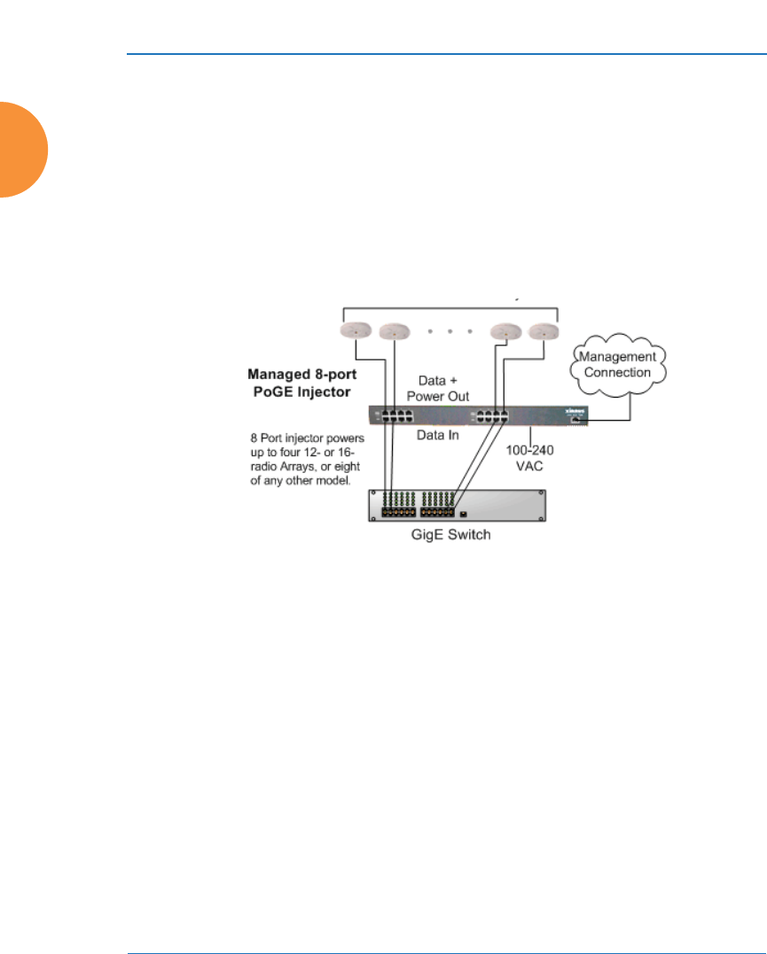
Wireless Access Point
16 Introduction
Power over Ethernet (POE)
Some smaller APs (XR-2000 models ending in “5” or “6”, and XR-500/600 Series)
are compatible with IEEE802.3af and/or IEEE802.3at PoE+, and may be
connected to appropriate powered switches. For example, the Xirrus XT-5024 and
XT-5048 are 24-and 48-port 802.3at POE+ managed switches. See the Installation
Guide for the AP for compatible injectors or powered switches.
POE modules provide power to APs over the same Cat 5e or Cat 6 cable used for
data. Managed modules provide the ability to control power using XMS.
Figure 4. XP8 - Power over Ethernet Usage
Specific models of the AP are compatible with specific POE modules.
Enterprise Class Management
The Wireless AP can be used with its default settings, or it can be initially
configured using zero touch cloud-based automated provisioning. Settings may
also be customized using the AP’s embedded WMI. The WMI enables easy

Wireless Access Point
Introduction 17
configuration and control from a graphical console, plus a full complement of
troubleshooting tools and statistics.
Figure 5. WMI: AP Status
In addition, a fully featured Command Line Interface (CLI) offers IT professionals
a familiar management and control environment. Simple Network Management
Protocol (SNMP) is also supported to allow management from an SNMP
compliant management tool, such as the optional XMS.
#For deployments of more than five APs, we recommend that you use the
cloud-based or enterprise version of XMS. XMS offers a rich set of features
for fine control over large deployments.
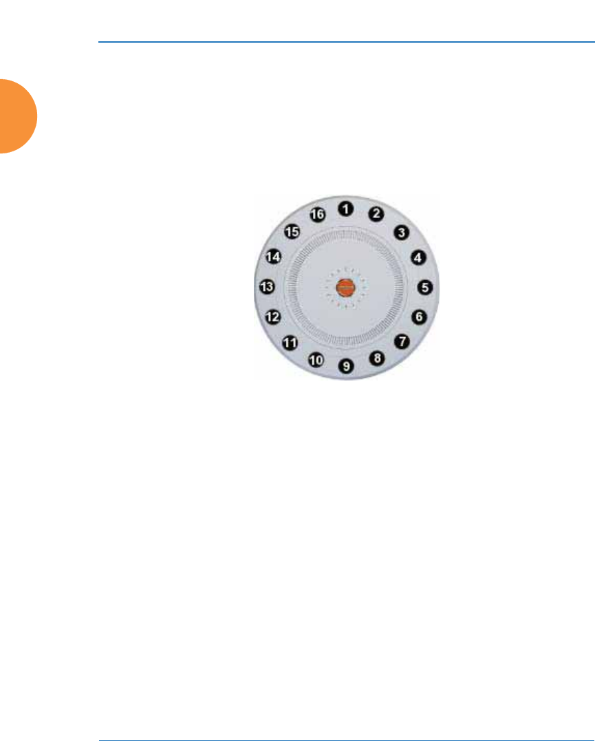
Wireless Access Point
18 Introduction
Key Features and Benefits
This section describes some of the key product features and the benefits you can
expect when deploying the Wireless AP (the XR-7630 product is used as an
example in this section).
High Capacity and High Performance
Figure 6. Layout of IAPs (XR-7630)
The XR-7630 version of the Wireless AP (Figure 6) enables wireless connectivity
and easily handles time-sensitive traffic such as voice. This model includes four
Gigabit uplink ports for connection to the wired network. Its sixteen IAPs (radios)
provide a maximum wireless capacity of 7.2 Gbps, which offers ample reserves
for the high demands of current and future applications. Of the sixteen IAPs,
fifteen operate as radios which may be set up to serve your choice of client
types — any or all of 802.11a/b/g/n (5 GHz or 2.4 GHz bands), providing
backwards compatibility with 802.11b and 802.11g.
In the recommended configuration, one IAP is configured in RF monitoring and
intrusion detection/prevention mode.
Extended Coverage
One XR-7630 solution enables you to replace fifteen access points (including one
omni-directional IAP for monitoring the network). Fifteen IAP radios with
integrated directional antennas provide increased wireless range and enhanced
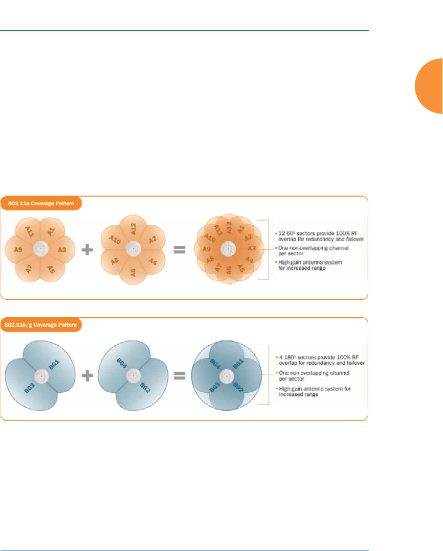
Wireless Access Point
Introduction 19
data rates in all directions. With a Wireless AP deployed, far fewer access points
are needed and wired-like resiliency is delivered throughout your wireless
network. Your Wireless AP deployment ensures:
z
Continuous connectivity if an IAP (radio) fails.
z
Continuous connectivity if an AP fails.
z
Continuous connectivity if a WDS link or switch fails.
z
Continuous connectivity if a Gigabit uplink or switch fails.
Flexible Coverage Schemes
Figure 7. Coverage Schemes (XR-7230 shown)
z
802.11a/n
Delivers 60° wireless coverage per IAP, with 6 dBi of gain.
z
802.11b/g/n
Delivers 180° wireless coverage, with 3 dBi of gain.

Wireless Access Point
20 Introduction
z
802.11a/b/g/n (monitor only)
Delivers 360° wireless coverage, with 2 dBi of gain.
Non-Overlapping Channels
Complete use of non-overlapping channels limits interference and delivers
maximum capacity. On the XR-7630, up to 16 non-overlapping channels are fully
utilized across the 5GHz and 2.4GHz spectrums.
SDMA Optimization
SDMA (Spatial Division Multiple Access) technology provides full 360° coverage
while allowing independent channel and power output customization. Also
supports fast inter-zone handoffs for time-sensitive applications and roaming.
Fast Roaming
Fast roaming utilizes the Xirrus Roaming Protocol ensuring fast and seamless
roaming capabilities between IAPs or APs at both Layer 2 and Layer 3.
Ease of Deployment
Xirrus XMS simplifies and speeds deployment of the wireless network by
automatically setting up each AP’s license, software image, and initial
configuration. When the AP is installed and has Internet connectivity, it contacts
Xirrus, which performs these initialization tasks.
Powerful Management
The XMS offers real time monitoring and management capabilities for the
wireless network.
Secure Wireless Access
Multiple layers of authentication and encryption ensure secure data
transmissions. The Wireless AP is 802.11i compliant with line-rate encryption
support for 40 and 128 bit WEP, WPA and WPA2 with TKIP and AES encryption.
Authentication is provided via 802.1x, including PEAP, EAP-TLS, EAP-TTLS,
EAP-SIM, EAP-GTC, EAP-AKA, EAP-AKA-Prime, and Lightweight Extensible
Authentication Protocol (LEAP) passthrough. Intrusion detection and prevention
provide proactive monitoring of the environment for threats.

Wireless Access Point
Introduction 21
Applications Enablement
The Wireless AP’s Quality of Service (QoS) functionality combined with true
switch capabilities enable high density video and Voice over Wireless LAN
deployments. Compliant with 802.1p and 802.1Q standards.
See Also
Wireless Access Point Product Overview
Power over Ethernet (POE)
Why Choose the Xirrus Access Point?
Advanced Feature Sets
The Wireless AP offers a family of powerful functionality packages, including the
RF Performance Manager (RPM), RF Security Manager (RSM), RF Analysis
Manager (RAM), and Application Control. These four packages are separately
licensed for operation on your AP. RPM, RSM, and RAM are automatically
included as part of all APs. Application Control is an optional feature.
Xirrus Advanced RF Performance Manager (RPM)
The Xirrus RPM optimizes the bandwidth usage and station performance of
wireless networks. Leveraging the multiple integrated access point (multi-radio)
design of the Xirrus Wireless AP, RPM manages the allocation of wireless
bandwidth to wireless stations across multiple RF channels. The result maximizes
overall network performance with superior flexibility and capacity.
Today's wireless infrastructure is faced with ever increasing numbers and
variations of wireless enabled clients, whether in the form of notebooks, tablets,
smart phones, IP phones, printers, projectors, cameras, RFID tags, etc. The advent
of higher speed wireless and its increased use of the 5GHz spectrum adds to the
number of variables today's wireless networks must accommodate. Backwards
compatibility with older clients is crucial, however their operation in a wireless
network can significantly hinder the performance of faster clients. As an example,
802.11b wireless stations communicate more than 10 times slower than 802.11n
stations.

Wireless Access Point
22 Introduction
With each of the AP’s multiple radios operating on a different channel, RPM
selects the ideal radio for each station. High-speed stations are grouped together
on radios with other high speed stations, while lower speed stations are combined
with other lower speed stations. This ensures optimal performance for high-speed
802.11ac stations without compromise.
The complete feature set of the RPM package includes:
z
Wireless Distribution System (WDS) for point-to-point communication
z
Wireless Mode per IAP
z
Sharp Cell technology
z
Wireless Data Rate Optimization
z
Wireless Traffic Shaping
z
Wireless Voice Call Admission Control
z
Fast Layer 2 and 3 Roaming
z
Standby Mode
Xirrus Advanced RF Security Manager (RSM)
The Xirrus RSM improves security and minimizes the risk in deploying 802.11
wireless networks. Leveraging an integrated 24/7 threat sensor and hardware-
based encryption/decryption in each AP, RSM secures the wireless network from
multiple types of threats. The result delivers uncompromised overall network
security with superior flexibility and performance.
Wireless networks face a number of potential security threats in the form of rogue
access points, ad-hoc clients, unauthorized clients, wireless-based attacks,
eavesdropping, etc. As “bring your own device” (BYOD) becomes ubiquitous in
enterprise networks, defending against these threats becomes more critical. With
the AP’s threat sensor radio scanning all channels in the 2.4GHz and 5GHz
spectrums, RSM searches for security threats and automatically mitigates them.
High performance encryption/decryption in the enterprise wireless network is a
must. The wireless network needs to support each client using the highest level of
encryption (WPA2 Enterprise/128 bit AES) and without degrading the overall
performance of the network. Xirrus incorporates hardware-based encryption/

Wireless Access Point
Introduction 23
decryption into each AP, delivering line-rate encryption at the edge of the
network instead of at a choke point within a centralized controller.
The complete feature set of the RSM package includes:
z
Wireless IDS/IPS (Intrusion Detection/Prevention System)
z
Wireless stateful firewall
z
User group policies
z
Authenticated guest access gateway
z
NAC integration
Xirrus Advanced RF Analysis Manager (RAM)
The RF Advanced Analysis Manager (RAM) tests and troubleshoots wireless
networks. The deployment of 802.11ac presents a set of unique challenges based
on technology differences with legacy 802.11a/b/g/n networks, both on the
wireless infrastructure and client side. Xirrus RAM equips each Wireless AP with
a powerful set of tools and features to optimally tune and verify an 802.11ac
installation, as well as give IT administrators the ability to troubleshoot issues
that may occur within the wireless environment.
802.11ac deployment will continue to evolve over the next several years with
additional performance and optional functions, along with an ongoing stream of
IEEE 802.11 amendments. This changing wireless landscape mandates that
appropriate tools are available to the user to analyze, optimize, and troubleshoot
their changing environments.
The distributed architecture of the AP enables the execution of powerful wireless
and networking analysis at the edge of the network where packets traverse the
wireless-to-wired boundary. The AP includes an embedded wireless controller
with the necessary computing and memory resources to provide these functions
securely at the network's edge.
The key elements of the RAM package include:
z
RF Analysis – An embedded Spectrum Analyzer leverages the dedicated
threat sensor radio in each Wireless AP to provide a continual view of
utilization, interference, and errors across all available wireless channels.

Wireless Access Point
24 Introduction
z
Packet Analysis – Integrated packet capture provides filterable views of
all traffic traversing on the wired and wireless interfaces of the AP.
z
Performance Analysis – Embedded traffic generation enables the
throughput of the AP’s wireless or wired interfaces to be analyzed.
z
Failure Recovery – Radio Assurance provides an automatic self-test and
self healing mechanism that ensures continuous system operation.
z
Netflow Support
z
Network Tools: ping, RADIUS ping, traceroute
Xirrus Application Control
The Application Control feature is available on APs to provide real-time visibility
of application usage by users across the wireless network. Network usage has
changed enormously in the last few years, with the increase in smart phone and
tablet usage stressing networks.
The AP uses Deep Packet Inspection (DPI) to determine what applications are
being used and by whom, and how much bandwidth they are consuming. These
applications are rated by their degree of risk and productiveness. The results are
presented to you both graphically and in tables. Filters can be used to implement
per-application policies that keep network usage focused on productive uses,
eliminating risky and non-business-oriented applications such as BitTorrent. You
can increase the priority of mission-critical applications like VoIP and WebEx. See
“Application Control Windows” on page 150 for more information.

Wireless Access Point
Introduction 25
About this User’s Guide
This User’s Guide provides detailed information and procedures that will enable
wireless network administrators to install, configure and manage the Wireless AP
so that end users can take full advantage of the product’s features and
functionality without technical assistance.
Organization
Topics and procedures are organized by function under the following chapter
headings:
z
Introduction
Provides a brief introduction to wireless technology, an overview of the
product, including its key features and benefits, and presents the product
specifications.
z
Installing the Wireless AP
Defines prerequisites for deploying and installing the AP and provides
instructions to help you plan and complete a successful installation.
z
The Web Management Interface
Offers an overview of the product’s embedded Web Management
Interface, including its content and structure. It emphasizes what you
need to do to ensure that any configuration changes you make are
applied, and provides a list of restricted characters. It also includes
instructions for logging in to the AP with your Web browser.
z
Viewing Status on the Wireless AP
Describes the status and statistics displays available on the AP using its
embedded Web Management Interface.
z
Configuring the Wireless AP
Contains procedures for configuring the AP using its embedded Web
Management Interface.
z
Using Tools on the Wireless AP
Contains procedures for using utility tools provided in the Web
Management Interface. It includes procedures for upgrading the system

Wireless Access Point
26 Introduction
firmware, uploading and downloading configurations and other files,
using diagnostic tools, and resetting the AP to its factory defaults.
z
The Command Line Interface
Includes the commands and the command structure used by the Wireless
AP’s Command Line Interface (CLI), and provides a procedure for
establishing a Telnet connection to the AP. This chapter also includes
some sample key configuration tasks using the CLI.
z
Appendix A: Quick Reference Guide
Contains the product’s factory default settings.
z
Appendix B: FAQ and Special Topics
Offers guidance to resolve technical issues, including general hints and
tips to enhance your product experience, and a procedure for isolating
problems within an AP-enabled wireless network. Also includes
Frequently Asked Questions (FAQs) and Xirrus contact information.
z
Appendix D: Notices (XR-1000 to XR-6000 Indoor Models)
Contains the legal notices and compliance statements for the AP. Please
read this section carefully.
z
Appendix C: Notices (XD and XR500/600 Series Only)
Contains the legal notices and compliance statements for the XD and
XR500 Series Access Points. Please read this section carefully if you are
using these models.
z
Appendix E: Medical Usage Notices
Provides compliance information for Xirrus devices with respect to the
requirements of IEC 60601-1-2.
z
Appendix F: Auditing PCI DSS
Discusses using AP features to assist in meeting security standards for
PCI DSS audits.
z
Appendix G: Implementing FIPS Security
Discusses meeting FIPS security standards with Xirrus devices.

Wireless Access Point
Introduction 27
z
Glossary of Terms
Provides an explanation of terms directly related to Xirrus product
technology, organized alphabetically.
z
Index
The index is a valuable information search tool. Use the index to locate
specific topics discussed in this User’s Guide. Simply click on any page
number in the index to jump to the referenced topic.
Notes and Cautions
The following symbols are used throughout this User’s Guide:
Screen Images
Some screen images of the Web Management Interface have been modified for
clarity. For example, an image may have been cropped to highlight a specific area
of the screen, and/or sample data may be included in some fields.
Product Specifications
Please refer to the Xirrus web site for the latest specifications for these APs—
www.xirrus.com.
#This symbol is used for general notes that provide useful supplemental
information.
!This symbol is used for cautions. Cautions provide critical information that
may adversely affect the performance of the product.

Wireless Access Point
28 Introduction

Wireless Access Point
Installing the Wireless AP 29
Installing the Wireless AP
The instructions for planning and completing a successful installation include the
following topics:
z
“Installation Prerequisites” on page 29.
z
“Planning Your Installation” on page 32.
z
“Installation Workflow” on page 67.
z
“Installing Your Wireless AP” on page 69.
z
“Powering Up the Wireless AP” on page 72.
z
“Zero-Touch Provisioning and Ongoing Management” on page 75.
z
“Performing the Express Setup Procedure” on page 80.
Installation Prerequisites
Wireless AP deployment requires the presence of hardware and services in the
host wired/wireless network, including:
z
Power Source
Xirrus APs are powered via Xirrus-supplied Power over Ethernet. POE
supplies power over the same Cat 5e or Cat 6 cable used for data, thus
reducing cabling and installation effort. POE power injector modules are
available in 1-, 2-, and 8-port configurations and are typically placed near
your Gigabit Ethernet switch. An AC outlet is required for each injector
module.
Some smaller APs are compatible with IEEE802.3af and/or IEEE802.3at,
and may be connected to appropriate powered switches. For example, the
Xirrus XT-5024 is a 24-port 802.3at PoE+ managed switch. See the
Installation Guide for the AP for compatible injectors or powered
switches.
z
Ethernet ports
You need at least one 100/1000 BaseT port to establish wired Gigabit
Ethernet connectivity. XR Series APs have different numbers of ports,

Wireless Access Point
30 Installing the Wireless AP
depending on the model (see “XR Wireless AP Product Family” on
page 5).
z
Secure Shell (SSH) utility
To establish secure remote command line access to the AP, you need a
Secure Shell (SSH) utility, such as PuTTY. The utility must be configured
to use SSH-2, since the AP will only allow SSH-2 connections.
z
Secure Web browser
Xirrus supports the latest version of the following Browsers: Internet
Explorer, Mozilla Firefox, Chrome, or Safari. A secure Web browser is
required for Web-based management of the AP. The browser must be on
the same subnet as the AP, or you must set a static route for management
as described in the warning above.
z
Serial connection capability
A serial port (console) is present on most XR-2000 models and all larger
XR series models. The Xircon utility can be used in place of a console
port—see the Xircon User’s Guide. To connect directly to the console port
on the AP, your computer must be equipped with a male 9-pin serial port
and terminal emulation software (for example, HyperTerminal). The
Xirrus AP only supports serial cable lengths up to 25’ per the RS-232
specification.
Use the following settings when establishing a serial connection:
!The AP’s Ethernet ports should be connected to an Ethernet switch, not an
Ethernet hub — if a hub is used, we recommend that you do not bond-pair
Ethernet ports.
Bits per second 115,200
Data bits 8
Parity None
Stop bits 1
Flow control None

Wireless Access Point
Installing the Wireless AP 31
Optional Network Components
The following network components are optional.
z
Xirrus Management System (XMS)
The optional XMS offers powerful management features for small or large
Wireless AP deployments.
Client Requirements
The Wireless AP should only be used with Wi-Fi certified client devices.
See Also
Coverage and Capacity Planning
Failover Planning
Planning Your Installation

Wireless Access Point
32 Installing the Wireless AP
Planning Your Installation
This section provides guidelines and examples to help you plan your Xirrus
Wireless AP deployment to achieve the best overall coverage and performance.
We recommend you conduct a site survey to determine the best location and
settings for each AP you install.
z
“General Deployment Considerations” on page 32
z
“Coverage and Capacity Planning” on page 34
z
“About IEEE 802.11ac” on page 42
z
“Failover Planning” on page 52
z
“Power Planning” on page 55
z
“Security Planning” on page 56
z
“Port Requirements” on page 58
z
“Network Management Planning” on page 62
z
“WDS Planning” on page 63
z
“Common Deployment Options” on page 66
General Deployment Considerations
The Array’s unique multi-radio architecture generates 360 degrees of sectored
high-gain 802.11a/b/g/n/ac coverage that provides extended range. (Note that
XR-500/600 Series radios are omni-directional rather than sectored.) The number,
thickness and location of walls, ceilings or other objects that the wireless signals
must pass through may affect the range. Typical ranges vary depending on the
types of materials and background RF (radio frequency) noise at your location. To
maximize wireless range, follow these basic guidelines:
1. Keep the number of walls and ceilings between the AP and your
receiving devices to a minimum — each wall or ceiling can reduce the
wireless range from between 3 and 90 feet (1 to 30 meters). Position your
devices so that the number of walls or ceilings is minimized.
#For optimal placement of APs, we recommend that a site survey be
performed by a qualified Xirrus partner.

Wireless Access Point
Installing the Wireless AP 33
2. Be aware of the direct line between each device. For example, a wall that
is 1.5 feet thick (half a meter) at 90° is actually almost 3 feet thick (or 1
meter) when viewed at a 45° angle. At an acute 2° degree angle the same
wall is over 42 feet (or 14 meters) thick. For best reception, try to ensure
that your wireless devices are positioned so that signals will travel
straight through a wall or ceiling.
Figure 8. Wall Thickness Considerations
3. Try to position wireless client devices so that the signal passes through
drywall (between studs) or open doorways and not other materials that
can adversely affect the wireless signal.
See Also
Coverage and Capacity Planning
Common Deployment Options
Installation Prerequisites
90° 45°
1.5 feet/
.5 m ~ 3 feet/
1 m
> 42 feet\
14 m
2°
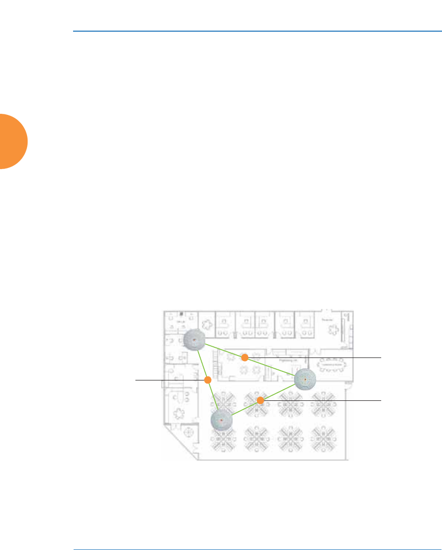
Wireless Access Point
34 Installing the Wireless AP
Coverage and Capacity Planning
This section considers coverage and capacity for your deployment(s), including
placement options, RF patterns and cell sizes, area calculations, roaming
considerations, and channel allocations.
Placement
Use the following guidelines when considering placement options:
1. The best placement option for the AP is ceiling-mounted within an open
plan environment (cubicles rather than fixed walls).
2. Keep the AP away from electrical devices or appliances that generate RF
noise. Because the AP is generally mounted on ceilings, be aware of its
position relative to lighting (especially fluorescent lighting) — we
recommend maintaining a distance of at least 3 to 6 feet (1 to 2 meters).
Figure 9. Unit Placement
3. If using multiple APs in the same area, maintain a distance of at least
100ft/30m between APs if there is direct line-of-sight between units, or at
least 50ft/15m if a wall or other barrier exists between units.
#XR-500/600 Series Integrated Access Points are omni-directional rather than
directional (sectored), and discussions involving sectored radios are not
applicable to these APs.
100 ft/ 30 m
100 ft/ 30 m
100 ft/
30 m

Wireless Access Point
Installing the Wireless AP 35
RF Patterns
The Wireless AP allows you to control — automatically or manually — the pattern
of wireless coverage that best suits your deployment needs. You can choose to
operate with full coverage, half coverage, or custom coverage (by enabling or
disabling individual sectors).
Full (Normal) Coverage
In normal operation, the AP provides a full 360 degrees of coverage.
Figure 10. Full (Normal) Coverage
Half Coverage
Figure 11. Adjusting RF Patterns
If installing a unit close to an exterior wall, you can deactivate half of the radios to
prevent redundant signals from “bleeding” beyond the wall and extending
service into public areas. The same principle applies if you want to restrict service
to an adjacent room within the site.
outside wall

Wireless Access Point
36 Installing the Wireless AP
Custom Coverage
Where there are highly reflective objects in proximity to the AP, you can turn off
specific radios to avoid interference and feedback.
Figure 12. Custom Coverage
Capacity and Cell Sizes
Cell sizes should be estimated based on the number of users, the applications
being used (for example, data/video/voice), and the number of APs available at
the location. The capacity of a cell is defined as the minimum data rate desired for
each sector multiplied by the total number of sectors being used.
Figure 13. Connection Rate vs. Distance
Figure 13 shows relative connection rates for 802.11n vs. 802.11a/g and 802.11b,
and the effect of distance on the connection rates. 802.11ac rates behave like
802.11n over distance—see Figure 23 for 802.11ac data rates). Wireless
environments can vary greatly so the actual rates may be different depending on
the specific network deployment.
object
reflective

Wireless Access Point
Installing the Wireless AP 37
Fine Tuning Cell Sizes
Adjusting the transmit power allows you to fine tune cell sizes. There are four
standard sizes — Small, Medium, Large, or Max (the default is Max). There is also
an Auto setting that automatically determines the best cell size, and a Manual
setting that allows you to choose your power settings directly.
Figure 14. Transmit Power
Auto Cell Size is an automatic, self-tuning mechanism that balances cell size
between APs to guarantee coverage while limiting the RF energy that could
extend beyond the organizational boundary. Auto Cell uses communication
between APs to dynamically set radio power so that complete coverage is
provided to all areas, yet at the minimum power level required. This helps to
minimize potential interference with neighboring networks. Additionally, APs
running Auto Cell automatically detect and compensate for coverage gaps caused
by system interruptions. To enable the Auto Cell Size feature, go to “RF Power
and Sensitivity” on page 361.
There are two ways of performing Auto Cell Size—by band (Multichannel Auto
Cell) or by channel (this is the default version). Auto Cell by channel adjusts the
size of two or more neighboring AP radios that are on the same channel (Figure 15
A and B). Multichannel Auto Cell adjusts cell sizes of neighboring radios on the
same band (2.4GHz or 5GHz) even if they are on different channels. A potential
application of Autocell by Band is depicted in Figure 15 B and C. In this example,
Large
Medium
Small
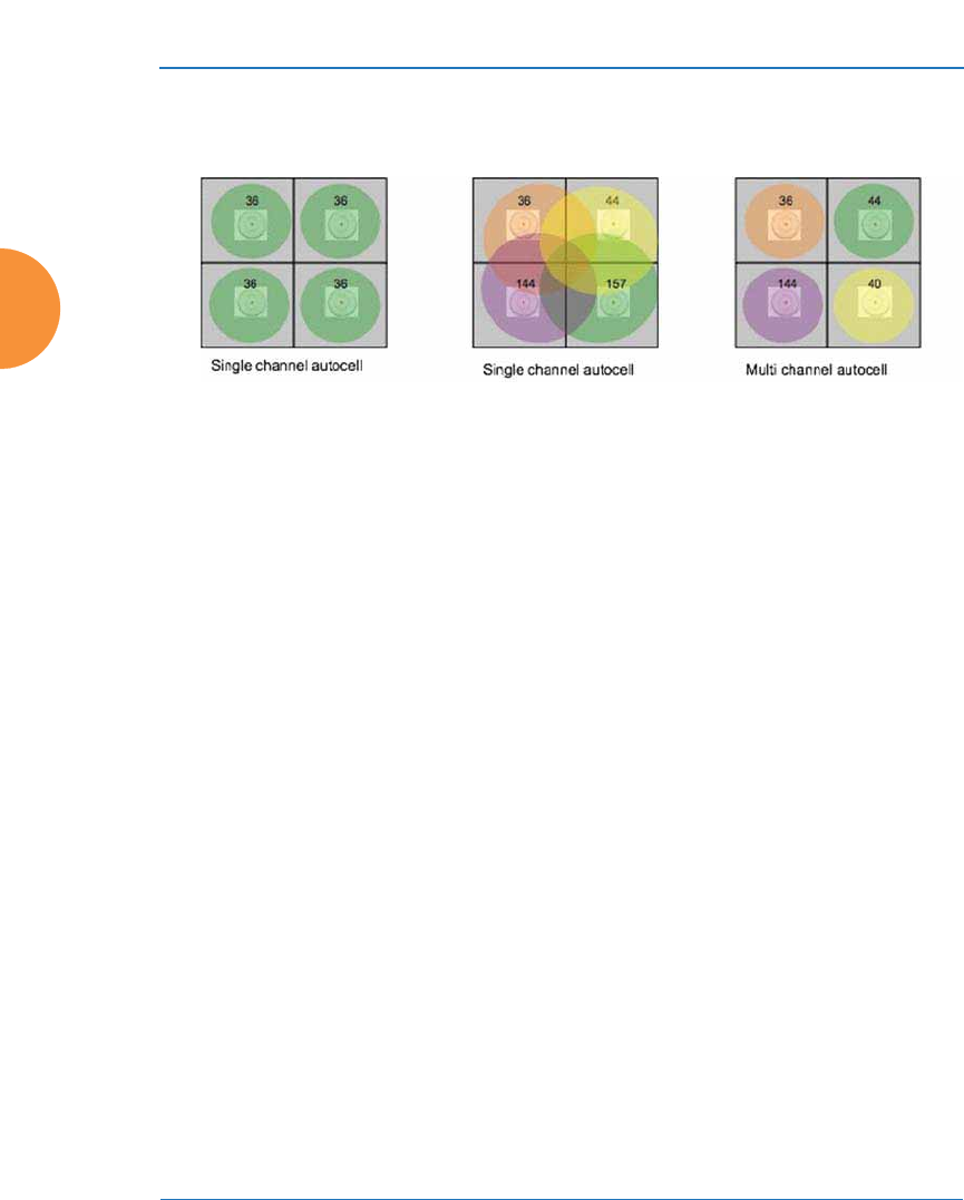
Wireless Access Point
38 Installing the Wireless AP
cell sizes are to be adjusted so that they are contained in each room. The goal is for
stations to associate to the AP located in the same room with them.
Figure 15. Auto Cell Size Options
Multichannel Auto Cell is configured by turning off Auto Cell by Channel in
“Procedure for Configuring Global 802.11an IAP Settings” on page 335 for the
5GHz band, and in “Procedure for Configuring Global 802.11b/g IAP Settings”
on page 342 for the 2.4GHz band. Note that Multichannel Auto Cell is run
separately for each band. Thus, to optimize cell size of both 2.4G and 5G, the
Auto Cell function should be run once for each of these pages. APs must be at
least 15 feet apart for Auto Cell to work properly.
If you are installing many units in proximity to each other, we recommend that
you use Auto Cell Size; otherwise, reduce the transmit power using manual
settings to avoid excessive interference with other APs or installed APs. See also,
“Coverage and Capacity Planning” on page 34.
Sharp Cell
This patented Xirrus RF management option automatically creates more
intelligently defined cells and improves performance by creating smaller, high-
throughput cells. By dynamically limiting each cell to a defined boundary (cell
size), the trailing edge bleed of RF energy is reduced, thus minimizing
interference between neighboring Wireless APs or other Access Points. To enable
the Sharp Cell feature, go to “RF Power and Sensitivity” on page 361.
ABC

Wireless Access Point
Installing the Wireless AP 39
Roaming Considerations
Cells should overlap approximately 10 - 15% to accommodate client roaming.
Figure 16. Overlapping Cells
Allocating Channels
Because the Wireless AP is a multi-channel device, allocating the best channels to
radios is important if peak performance is to be maintained.
Automatic Channel Selection
In the automatic mode, channels are allocated dynamically, driven by changes in
the environment. Auto Channel assignment is performed by scanning the
surrounding area for RF activity on all channels, then automatically selecting and
setting channels on the AP to the best channels available. This function is
typically executed when initially installing APs in a new location and may
optionally be configured to execute periodically to account for changes in the RF
environment over time. Auto Channel selection has significant advantages,
including:
#Note that Auto Channel normally assigns individual channels. However, if
you select Auto bond 5GHz channels on the Global Settings .11n page,
and have 40MHz channels set up prior to running Auto Channel, those
bonds will be preserved. 80MHz bonds will not be preserved.
ROAMING
10 - 15% overlap

Wireless Access Point
40 Installing the Wireless AP
z
Allows the AP to come up for the first time and not interfere with existing
equipment that may be already running, thereby limiting co-channel
interference.
z
More accurately tunes the RF characteristics of a wireless installation than
manual configuration since the radios themselves are scanning the
environment from their physical location.
z
May be configured to run periodically.
To set up the automatic channel selection feature, go to “Advanced RF Settings”
on page 358.
Manual Channel Selection
You can manually assign channels on a per radio basis, though manual selection
is not recommended (and not necessary).
Figure 17. Allocating Channels Manually
#To avoid co-channel interference, do not select adjacent channels for radios
that are physically next to each other.
Maintain channel separation

Wireless Access Point
Installing the Wireless AP 41
Other Factors Affecting Throughput
Throughput of the AP can be affected by many factors such as distance, number
of stations, obstacles, construction materials used at the site, etc. In addition,
features applied to traffic may have an effect. Performance may decrease as you
add increasing numbers of SSIDs, VLANs, and features such as Application
Control, encryption, management via XMS-Cloud, etc. XR-500/1000 Series
models are more prone to performance degradation since they have less memory
than other models.
See Also
Failover Planning
Installation Prerequisites

Wireless Access Point
42 Installing the Wireless AP
About IEEE 802.11ac
802.11ac is a continuation of the IEEE 802.11 standard. It multiplies the maximum
data rate—eventually, up to ten times the 802.11n maximum. Along with
increased data rates, it offers simultaneous transmission to multiple clients.
802.11ac will be rolled out in two phases. Wave 1 products currently available
support 80MHz channels and up to 3 data streams for a maximum data rate of 1.3
Gbps. Wave 2 and future products will add 160MHz channels and up to 8
streams, for a maximum data rate of 6.93Gbps.
Xirrus currently supports up to three streams (in units with 3x3 radios) and 80
MHz channels. Xirrus models that offer 802.11ac support this technology on all
IAPs, not just on one. IAPs are individually configurable to different modes or
groups of modes (such as 802.11a, 11b, 11g, and 11n). Xirrus optimizes 802.11ac
performance with ACExpress™, an innovation that intelligently separates fast
and slow devices on separate IAPs to maximize system performance.
The major advantages of 802.11ac are:
z
Faster speeds than 802.11n over the same coverage area, operating at up
to 1.3 Gbps in Wave 1 implementations. While the maximum distance
that a Wi-Fi signal can reach is unchanged with 802.11ac, multiple
antennas increase the data rate at every distance.
z
Operates only in the less congested 5 GHz spectrum, which offers
“cleaner” air and supports much greater capacity than the 2.4 GHz
spectrum still used by 802.11n.
z
Supports simultaneous communications to multiple clients on a single
channel with multi-user MIMO in future Wave 2 products.
z
Extends the techniques pioneered in 802.11n: more antennas, more spatial
streams and wider channels to improve throughput.
The techniques that 802.11ac uses to realize these performance improvements and
the expected results are discussed in:
z
“Up to Eight Simultaneous Data Streams — Spatial Multiplexing” on
page 44
z
“MIMO (Multiple-In Multiple-Out)” on page 44

Wireless Access Point
Installing the Wireless AP 43
z
“MU-MIMO (Multi-User Multiple-In Multiple-Out)” on page 45
z
“Higher Precision in the Physical Layer” on page 47
z
“80 MHz and 160 MHz Channel Widths (Bonding)” on page 48
z
“802.11ac Data Rates” on page 49
z
“ACExpress™” on page 50
It is important to consider 80 MHz and 160 MHz Channel Widths (Bonding) when
planning your deployment, since it contributes greatly to 802.11ac’s speed
improvements and because it is configured separately for each IAP. Your
selection of channel width in IAP Settings—40 MHz or 80 MHz or 20 MHz (if
bonding is turned off)—has a major effect on your channel planning. A global
setting is provided to enable or disable 802.11ac mode. See “Global Settings .11ac”
on page 350 to configure operation.
There are other factors to keep in mind when planning a roll-out of 802.11ac.
Please see “802.11ac Deployment Considerations” on page 50.
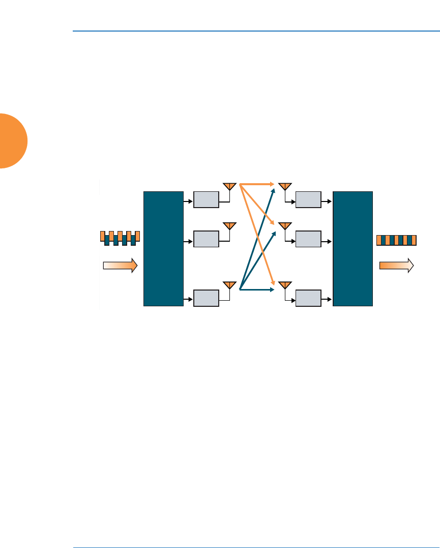
Wireless Access Point
44 Installing the Wireless AP
Up to Eight Simultaneous Data Streams — Spatial Multiplexing
Spatial Multiplexing transmits completely separate data streams on different
antennas (in the same channel) that are recombined to produce new 802.11ac data
rates. Previously used for 802.11n, the maximum number of streams for 802.11ac
has been increased to eight. Higher data rates are achieved by splitting the
original data stream into separate data streams. Each separate stream is
transmitted on a different antenna (using its own RF chain). MIMO signal
processing at the receiver can detect and recover each stream. Streams are then
recombined, yielding higher data rates.
Figure 18. Spatial Multiplexing
The date rate increases directly with the number of transmit antennas used. Note
that mobile devices in the near future will support up to three or four streams at
most, with many supporting less.
MIMO (Multiple-In Multiple-Out)
MIMO (Multiple-In Multiple-Out) signal processing is one of the core
technologies of 802.11n and 802.11ac. It mitigates interference and maintains
broadband performance even with weak signals.
Prior to 802.11n, a data stream was transmitted via one antenna. At the receiving
end, the antenna with the best signal was selected to receive data. MIMO signal
processing uses multiple antennas to send and receive data. It takes advantage of
multipath reflections to improve signal coherence and greatly increase receiver
sensitivity (Figure 19). Multipath signals were considered to be interference by
M
Rx 1
Rx 2
Rx
M
M
Transmitter
Data Stream Data Stream
Receiver
Tx 1
Tx 2
Tx
N
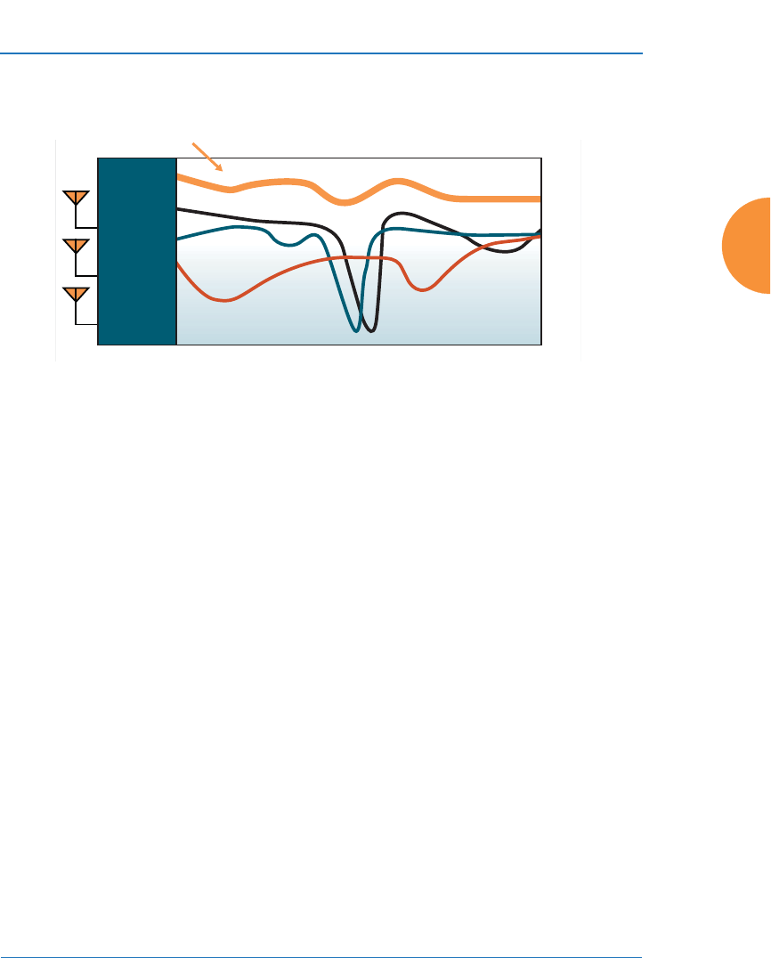
Wireless Access Point
Installing the Wireless AP 45
802.11a/b/g radios, and degraded performance. In 802.11n and 802.11ac, these
signals are used to enhance performance.
Figure 19. MIMO Signal Processing
802.11ac increases the number of antennas and spatial streams from a maximum
of four in 802.11n to a maximum of eight, contributing to much higher maximum
data rates (up to 6.93Gbit/s). The spatial streams can be concurrently allocated to
more than one receiving device when the AP operates in multi-user MIMO mode
(MU-MIMO, see the next section).
MU-MIMO (Multi-User Multiple-In Multiple-Out)
MU-MIMO (multi-user multiple-in/multiple-out) signal processing uses multiple
antennas on the transmitter and receiver operating on the same channel. With
spatial multiplexing in 802.11ac, up to 8 data streams may be concurrently
transmitted. MU-MIMO’s innovation allows the streams to be split between
multiple devices at once.
With 802.11n, whenever the IAP transmitted data, all of the traffic at any instant of
time was directed to a single client. As a consequence, if a set of devices included
a mix of fast and slow client clients, the fast traffic was often substantially delayed
by the transmission to slower clients. 802.11ac MU-MIMO works by directing
some of the spatial streams to one client and other spatial streams to other clients,
up to four at a time
For example, in the figure below, the transmitter has four antennas. Three are
transmitting to an 802.11ac laptop that has three antennas, while the remaining
Frequency Across Subcarriers
Attenuation
Antenna 1 Signal
MIMO Processed Signal
Antenna 2 Signal
Antenna 3 Signal
Receiver
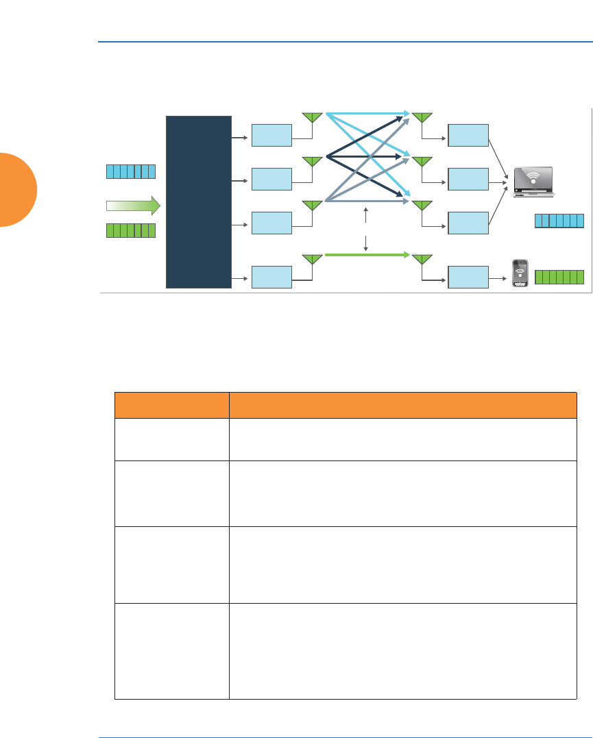
Wireless Access Point
46 Installing the Wireless AP
one is directed to a mobile phone. When a transmission is complete, the antennas
are reallocated.
Figure 20. MU-MIMO with Four Antennas
The table below illustrates how data streams might be allocated to multiple users
on an 802.11ac transmitter with multiple antennas.
# of AP Antennas Possible Combinations of Receiver Antennas
2 1 station w/ 2 antennas -or-
2 stations w/ 1 antenna
3 1 station w/ 3 antennas -or-
1 station w/ 2 antennas + 1 station w/ 1 antenna -or-
3 stations w/ 1 antenna
4 1 station w/4 antennas -or-
2 stations w/2 antennas -or-
1 station w/2 antennas + 2 stations w/1 antenna -or-
4 stations w/ 1 antenna
8 1 station w/ 8 antennas -or-
2 stations w/ 4 antennas -or-
1 station w/ 4 antennas + 2 stations w/ 2 antennas -or-
2 stations w/ 2 antennas + 4 stations w/1 antenna -or-
… many other combinations …
Spatial Streams
Rx 1
Rx 1
Rx 3
Data Stream
Data Stream
Data Stream
Tx 1
Tx 3
Rx 2Tx 2
Tx 4
Transmitter
(Access
Point)

Wireless Access Point
Installing the Wireless AP 47
Higher Precision in the Physical Layer
Wi-Fi utilizes several digital modulation techniques and automatically switches
between them to optimize for throughput or range. The basic unit of data
transmitted is called a symbol. The number of points in the modulation
constellation determines the number of bits of data conveyed with each symbol.
Figure 21. Physical Layer Data Encoding
802.11n uses 16 Quadrature Amplitude Modulation (QAM), which conveys
log2(16) = 4 bits per symbol and 64 QAM, which conveys 6 bits per symbol.
802.11ac adds 256 QAM which conveys 8 bits per symbol for a 33% increase in
throughput vs. the highest 802.11n data rate.
You may select the highest Modulation and Coding Scheme (MCS) level allowed
with 1, 2, or 3 Spatial Streams (see the Max MCS setting in “Procedure for
Configuring Global 802.11ac IAP Settings” on page 351). You may limit the
highest level of modulation to 64-QAM, or allow 256-QAM. It also determines the
coding scheme used for error correction. Higher MCS levels allocate fewer bits to
error correction, and thus more bits are used for data. The default value is MCS9,
the highest level.
256-QAM
I
Q
64-QAM
Q
+1
-1 +1 +3 +5 +7-3-5-7
+3
+5
+7
I
-7
-5
-3
-1
I
Q
Phase˚
Amplitude

Wireless Access Point
48 Installing the Wireless AP
The higher the MCS value, the higher the data rate, as shown in the table below.
Xirrus APs support MCS7 -MCS9. Higher MCS levels require higher signal-to-
noise ratios (i.e., a less noisy environment) and shorter transmission distances.
80 MHz and 160 MHz Channel Widths (Bonding)
Channel bonding increases data rates by combining two, four, or eight adjacent 20
MHz channels into one channel. This increases the data rate proportional to the
width of the bond.
Bonding is specified on the IAP Settings page for each IAP in terms of the primary
channel and the width of the bond. Be aware that Channel Bonding impacts
channel planning, since you are using multiple channels per IAP.
802.11ac allows creation of 20, 40, 80, or 160 MHz wide channels. The 160MHz
channel can also be a combination of two non-contiguous 80MHz channels
(80+80). Although channel bonding increases bandwidth, wider channels are
more susceptible to signal interference which may lead to reduced range and
poorer signal quality. Figure 22 is an example showing how Channels 36-64 may
MCS index value Modulation Code rate (R)
0BPSK1/2
1QPSK1/2
2QPSK3/4
3 16-QAM 1/2
4 16-QAM 3/4
5 64-QAM 2/3
6 64-QAM 3/4
7 64-QAM 5/6
8 256-QAM 3/4
9 256-QAM 5/6

Wireless Access Point
Installing the Wireless AP 49
be used: as eight 20 MHz channels; four 40 MHz channels; two 80 MHz channels;
or one 160 MHz channel. Xirrus currently supports channels up to 80 MHz wide.
Figure 22. Channel Bonding (Channels 36-64 shown)
802.11ac Data Rates
Figure 23. Maximum 802.11ac Data Rates
Frequency
Channel
Number 36
5150MHz
Channel Bandwidth
5250MHz
5350MHz
40 44 48 52 60
56 64
20MHz
40MHz
80MHz
160MHz
2-20MHz
bonded channels
2-40MHz
bonded channels
2-80MHz
bonded channels
UNII-1 UNII-2
Phase 1
Phase 2+
Maximum # Transmit Bandwidth #
Data Rate Antennas (MHz) Streams Modulation
293Mbps 1 40 1 64QAM
433Mbps 1 80 1 256QAM
867Mbps 2 80 2 256QAM
1.299Gbps 3 80 3 256QAM
1.730Gbps 4 80 4 256QAM
3.470Gbps 8 80 8 256QAM
867Mbps 1 160 1 256QAM
1.730Gbps 2 160 2 256QAM
3.470Gbps 8 160 4 256QAM
6.930Gbps 8 160 8 256QAM

Wireless Access Point
50 Installing the Wireless AP
IEEE 802.11ac data rates are dependent on the number of spatial streams obtained
through the use of MU-MIMO, 80 vs. 160MHz channel widths, the number of
transmit antennas, and the type of modulation. Figure 23 shows the maximum
data rate achievable at each level, with many additional lower rates occurring at
each level dependent on signal level, signal to noise ratio in the environment, etc.
Phase 1 802.11ac, first available in consumer products in 2012 and enterprise
products in 2013, supports up to 80MHz channels and up to 3 spatial streams for a
maximum data rate of 1.3Gbps.
Phase 2 and beyond products, expected starting in 2014, will add 160MHz
channels and up to 8 spatial streams for a maximum data rate of 6.9Gbps.
ACExpress™
Xirrus 802.11ac IAPs use ACExpress™ to optimize wireless performance by
automatically separating faster 802.11ac clients from slower Wi-Fi clients. Since
Wi-Fi is a shared medium, this separation ensures that slower 802.11a/b/g/n
clients do not starve the performance of 802.11ac clients. For example, the data
rate of an 802.11n client is less than 25% of the rate of an 802.11ac client, and thus
will take four times as much air time for a given amount of data. This takes
available bandwidth away from faster clients, reducing their performance
significantly. ACExpress intelligently separates clients by type onto different
radios, grouping fast clients separately from slow clients, thereby maximizing
performance for all. ACExpress is supported on all Xirrus 802.11ac products, and
may be enabled or disabled as part of the Load Balancing feature. See Step 26 on
page 331.
802.11ac Deployment Considerations
The theoretical data rates shown are just that, theoretical. For 802.11ac
deployments, numerous factors affect real-world performance. These are some
important considerations in the deployment of networks that include 802.11ac:
z
Wireless networks are not wired networks. Wired network users who
share a Gigabit network can expect to see bursts of up to 900Mbps,
depending on their hardware. Maximum Wi-Fi data rates are reduced by
signaling overhead and media contention. Most 802.11ac users will see

Wireless Access Point
Installing the Wireless AP 51
data rates less than 100Mbps as the effective bandwidth is shared among
all devices connecting to a given radio.
z
Migration to 802.11ac will take time. Older Wi-Fi technologies will
continue to be with us for years. In order for 802.11ac to provide
maximum data rates, it is important to keep interference from earlier Wi-
Fi standards at a minimum. For example, 802.11n devices operating in the
5GHz band can slow down 802.11ac devices to 300Mbps or 450Mbps
depending on the 2x2 or 3x3 MIMO technology used.
z
Infrastructures must be upgraded as well. The bandwidth required out
of 802.11ac APs will certainly exceed 1Gbps and may reach 10Gbps. The
links from the APs to the core network must keep pace with this need.
Centralized firewalls, LAN controllers, and authentication servers may
also reach their limits. Migration to a decentralized architecture, with
intelligence at the edge of the network may be a more scalable solution,
avoiding single points of failure.
z
More power. Multi-antenna APs handling 802.11ac speeds will likely
require more power. Power planning for your access switches should be
carefully considered.
z
A new site survey may be needed. Wireless networks established as
recently as a few years ago were probably designed for coverage and not
capacity. APs were placed so that there were no dead zones, without
considering future capacity needs. With the increasing use of mobile
devices, new site surveys that ensure enough bandwidth for anticipated
usage should precede deployment of 802.11ac APs.
z
Manage application usage. With 802.11ac, a range of applications are
now practical on mobile devices that were previously only used over
wired networks or on laptops. Uncontrolled use of Wi-Fi bandwidth can
cause wireless networks to quickly degrade. Network control elements
must control use of applications and prioritize critical applications.
z
Upgrading with 802.11ac radio modules. Xirrus offers modular APs that
enable you to evolve the capacity of your Arrays as your needs grow.
XI Series 802.11ac Wireless Access Points (APs) are offered in two models:
867 Mbps (2X2 MIMO) or 1300 Mbps (3X3 MIMO).

Wireless Access Point
52 Installing the Wireless AP
When you add IAPs to an AP or replace 802.11n IAPs with 802.11ac
modules, the Access Point determines its model number based on the
count and types of radios. For example, if you add four 1300 Mbps (3X3
MIMO) IAPs to an XR-4420, the AP will display its model number as XR-
4836 because it now has eight 3x3 IAPs including 802.11ac radios.
Failover Planning
This section discusses failover protection at the unit and port levels. To ensure
that service is continued in the event of a port failure, you can utilize two Gigabit
Ethernet ports simultaneously as a bonded pair (on APs with two or more Gigabit
ports).
Figure 24. Port Failover Protection
# Xirrus highly recommends that the upgraded Array have a radio count that
matches one of our standard Arrays (e.g., XR-4000 with 4 or 8 radios, XR-
2000 with 2 or 4). The Array may have more of one type of radio than
another. For example, an upgraded XR-4830 may have six 802.11n radios
and two 802.11ac radios, or vice versa.
Ethernet switch
Multiple port connections

Wireless Access Point
Installing the Wireless AP 53
In addition, the AP has full failover protection between the bonded-pair Gigabit
ports (see following table).
The Wireless AP Gigabit Ethernet ports actually support a number of modes:
z
802.3ad Link Aggregation
z
Load Balancing
z
Broadcast
z
Link Backup
z
Mirrored
For more details on Gigabit port modes and their configuration, please see
“Bonds and Bridging” on page 173.
Interface Bridges
Data?
Bridges
Management Traffic?
Fails Over
To: IP address
Gigabit port Yes Yes Bonded
port DHCP or static
Bonded
Gigabit port Yes Yes Bonded
port Same
Wireless Access Point
54 Installing the Wireless AP
Switch Failover Protection
To ensure that service is continued in the event of a switch failure, you can
connect APs having multiple Gigabit ports to more than one Ethernet switch (not
a hub).
Figure 25. Switch Failover Protection
See Also
Coverage and Capacity Planning
Installation Prerequisites
Network Management Planning
Planning Your Installation
Power Planning
Security Planning
#Gigabit Ethernet connections must be on the same subnet.
Ethernet switch Backup switch
Ethernet connections

Wireless Access Point
Installing the Wireless AP 55
Power Planning
All AP models support Power over Ethernet (POE) with an integrated splitter.
Power over Ethernet
To deliver power to the AP, you must use Xirrus-supplied Power over Ethernet
(POE) modules or powered switches that are compatible with your AP. They
provide power over Cat 5e or Cat 6 cables to the AP without running power
cables — see Figure 4 on page 16.
Specific models of the AP are compatible with specific PoGE modules. For details,
please see the Power over Gigabit Ethernet Installation and User Guide.
See Also
Coverage and Capacity Planning
Failover Planning
Network Management Planning
Security Planning
#When using Cat 5e or Cat 6 cable, power can be provided up to a distance of
100m.
Certain models (XR-500/600 Series and some XR-2000 models) also accept
IEEE802.3af and/or IEEE802.3at powered switch ports.

Wireless Access Point
56 Installing the Wireless AP
Security Planning
This section offers some useful guidelines for defining your preferred encryption
and authentication method. For additional information, see “Understanding
Security” on page 226 and the Security section of “Frequently Asked Questions”
on page 522.
Wireless Encryption
Encryption ensures that no user can decipher another user’s data transmitted
over the airwaves. There are three encryption options available to you, including:
z
WEP-40bit or WEP-128bit
Because WEP is vulnerable to cracks, we recommend that you only use
this for legacy devices that cannot support a stronger encryption type.
z
Wi-Fi Protected Access (WPA)
This is much more secure than WEP and uses TKIP for encryption.
z
Wi-Fi Protected Access (WPA2) with AES
This is government-grade encryption — available on most new client
adapters — and uses the AES–CCM encryption mode (Advanced
Encryption Standard–Counter Mode).
Authentication
Authentication ensures users are who they say they are. Users are authenticated
when they attempt to connect to the wireless network and periodically thereafter.
The following authentication methods are available with the Wireless AP:
z
RADIUS 802.1x
802.1x uses a remote RADIUS server to authenticate large numbers of
clients, and can handle different authentication methods (EAP-TLS, EAP-
TTLS, EAP-PEAP, and EAP-LEAP Passthrough). Administrators may
also be authenticated via RADIUS when preferred, or to meet particular
security standards.
z
Xirrus Internal RADIUS server
Recommended for smaller numbers of users (about 100 or less). Supports
EAP-PEAP only

Wireless Access Point
Installing the Wireless AP 57
z
Pre-Shared Key
Uses a pass-phrase or key that is manually distributed to all authorized
users. The same passphrase is given to client devices and entered into
each AP.
z
MAC Access Control Lists (ACLs)
MAC access control lists provide a list of client adapter MAC addresses
that are allowed or denied access to the wireless network, and can be
used in addition to any of the above authentication methods. ACLs are
good for embedded devices, like printers and bar-code scanners (though
MAC addresses can be spoofed). The AP supports 1,000 global ACL
entries. You may also define per-SSID access control lists, with up to 1000
entries each.
Meeting PCI DSS Standards
The Payment Card Industry (PCI) Data Security Standard (DSS) was developed
by major credit card companies. It lays out a set of requirements that must be met
in order to provide adequate security for sensitive data. The AP may be
configured to assist in satisfying PCI DSS standards. For details, please see
“Auditing PCI DSS” on page 585. Note that the license installed on the AP must
include the Advanced RF Security Manager (RSM) to support the PCI audit
command.
Meeting FIPS Standards
The Federal Information Processing Standard (FIPS) Publication 140-2 establishes
a computer security standard used to accredit cryptographic modules. The
standard is a joint effort by the U.S. and Canadian governments. To implement
Level 2 security requirements of FIPS Level 2 on the Wi-Fi AP, see “Implementing
FIPS Security” on page 591.
See Also
Failover Planning
Network Management Planning
Power Planning
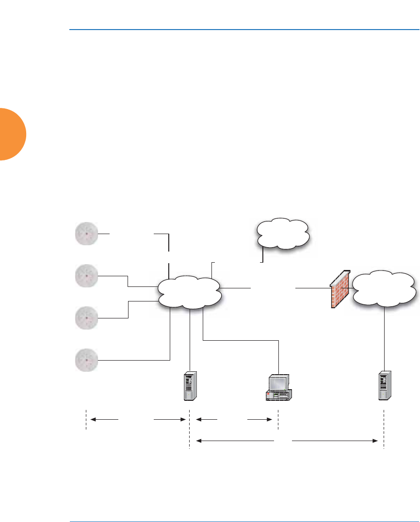
Wireless Access Point
58 Installing the Wireless AP
Port Requirements
A number of ports are used by various AP features and by the Xirrus
Management System (XMS). The Port Requirements table on page 59 lists ports
and the features that require them (XMS port requirements are included in the
table for your convenience). If you are using a feature, please make sure that the
ports that it requires are not blocked by firewalls or other policies, and that they
do not conflict with any other port assignments.
As an example, XMS port requirements are illustrated in Figure 26. XMS requires
ports 161, 162, and 443 to be passed between APs and the XMS server. Similarly,
port 9443 is required for communication between the XMS server and XMS
clients, and port 25 is typically used by the XMS server to access an SMTP server
to send email notifications.
Figure 26. Port Requirements for XMS
Firewall
XMS Server XMS Client*
L2 Switching
Infrastructure
SMTP Server*
Internal
Resources
External Network /
Internet
Ports:
9090, 9091
Ports:
161, 162, 443
SSID Traffic on
VLANs A, B, etc.
Management over
Native VLAN
Traffic from Arrays
VLAN B
Traffic from Arrays
VLAN A
Trunked 802.1q
VLAN Connection
Ports:
25
* XMS Client and SMTP Server may be internal or external resources.

Wireless Access Point
Installing the Wireless AP 59
The following table lists port requirements for the AP and for XMS, how the ports
are used, and whether they may be changed.
Port Application Peer Configurable
AP
icmp Ping XMS Server No
20 tcp
21 tcp FTP Client Yes
22 tcp SSH Client Yes
23 tcp Telnet Client Yes
25 tcp SMTP Mail Server No
69 udp TFTP TFTP Server No
123 udp NTP NTP Server No
161 udp SNMP XMS Server No
162 udp
SNMP Traphost Note -
Up to four Traphosts
may be configured.
XMS Server
Yes - but
required by
XMS
443 tcp HTTPS (WMI,WPR) Client Yes
514 udp Syslog Syslog Server No
1812, 1645
udp
RADIUS (some
servers use 1645) RADIUS Server Yes
1813, 1646
udp
RADIUS Accounting
(some servers still use
1646)
RADIUS Accounting
Server Yes
2055 udp Netflow Client Yes
5000 tcp Virtual Tunnel VTUN Server Yes
22610 udp Xirrus Roaming APs Yes
22612 udp Xircon (Console Utility) Admin Workstation Yes

Wireless Access Point
60 Installing the Wireless AP
XMS
icmp Ping APs No
22 tcp SSH APs Yes
25 tcp SMTP Mail Server Yes
123 udp NTP NTP Server No
161 udp SNMP APs No
162 udp SNMP Traphost 1 APs Via XMS
config file
443 tcp HTTPS APs No
514 udp Resident Syslog server Internal* Via XMS
config file
1099 tcp RMI Registry Internal* No
2000 tcp XMS Back-end Server Internal* No
3306 tcp MySQL Database Internal* No
8001 tcp Status Viewer Internal* No
8007 tcp Tomcat Shutdown Internal* During
installation
8009 tcp Web Container Internal* During
installation
9090 tcp XMS Webserver XMS client During
installation
9091 tcp XMS Client Server XMS client Via XMS
config file
9092 tcp XMS Client Server XMS client Via XMS
config file
9443 tcp XMS WMI SSL XMS web client Yes
* Internal to XMS Server, no ports need to be unblocked on other network devices
Port Application Peer Configurable

Wireless Access Point
Installing the Wireless AP 61
See Also
Management Control
External Radius
Services
VLAN Management

Wireless Access Point
62 Installing the Wireless AP
Network Management Planning
Network management can be performed using any of the following methods:
z
Centralized Web-based management, using the optional Xirrus
Management System (XMS). XMS-Cloud provides zero-touch
provisioning and ongoing management. XMS is hosted on a dedicated
Xirrus appliance or your own server. XMS manages large Wireless AP
deployments from a centralized Web-based interface and offers the
following features:
Globally manage large numbers of APs
Seamless view of the entire wireless network
Easily configure large numbers of APs
Rogue AP monitoring
Easily manage system-wide firmware updates
Monitor performance and trends
Aggregation of alerts and alarms
z
The AP’s Command Line Interface, using an SSH (Secure Shell) utility,
like PuTTY. The utility must be set up to use SSH-2, since the AP will only
allow SSH-2 connections.
z
Web-based management, using the AP’s embedded Web Management
Interface (WMI). This method provides configuration and basic
monitoring tools, and is good for small deployments (one or two units).
See Also
Failover Planning
Power Planning
Security Planning
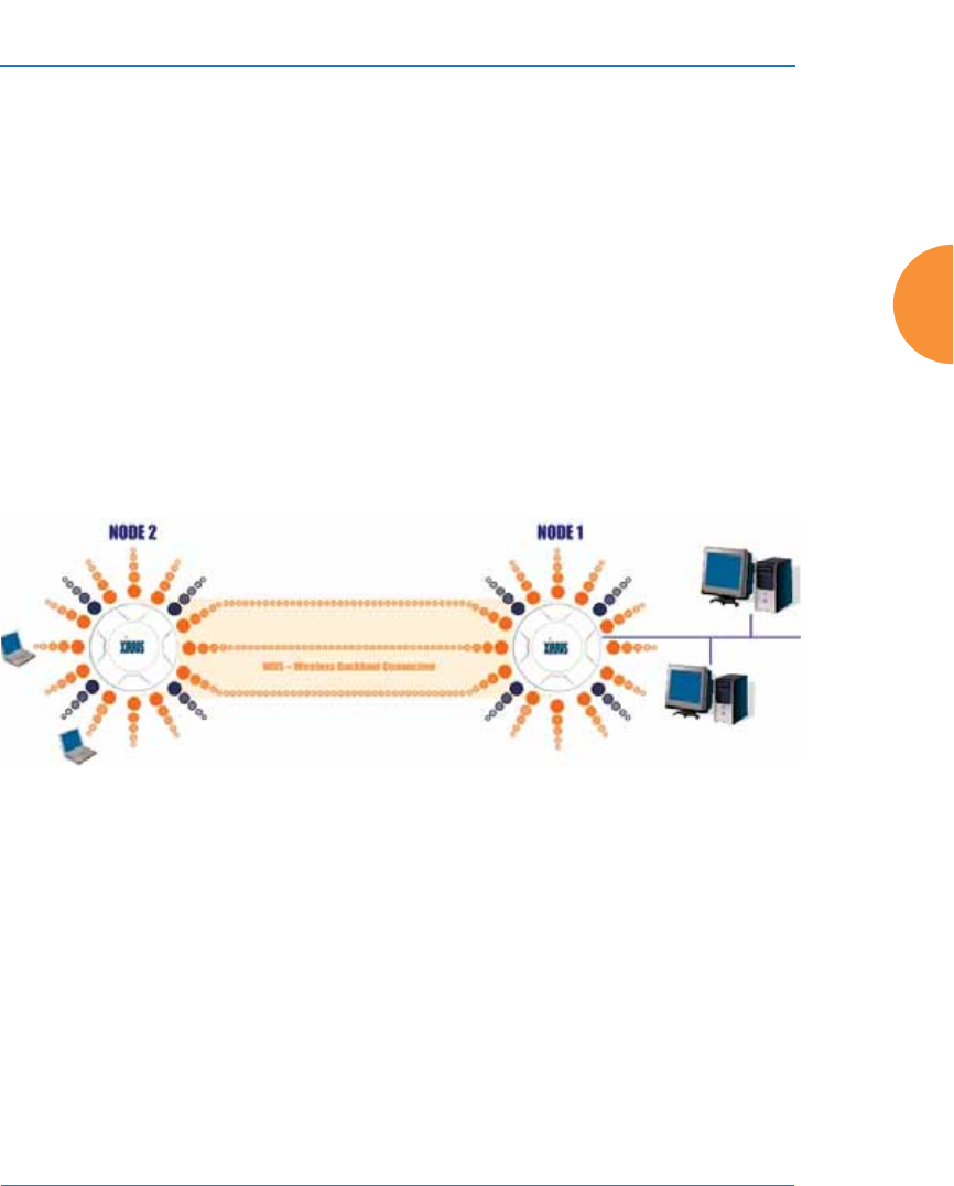
Wireless Access Point
Installing the Wireless AP 63
WDS Planning
WDS (Wireless Distribution System) creates wireless backhaul connections
between APs, allowing your wireless network to be expanded using multiple APs
without the need for a wired backbone to link them (see Figure 27). WDS features
include:
z
One to three IAPs may be used to form a single WDS link, yielding up to
1350 Mbps bandwidth per link. Up to three different WDS links may be
created on a single AP.
z
Automatic IAP load balancing
z
If desired, you may allow clients to associate to a BSS on the same radio
interface used for a WDS Host Link. This will take bandwidth from the
WDS link.
Figure 27. WDS Link
z
Multiple links per AP allow you to configure multi-hop connections.
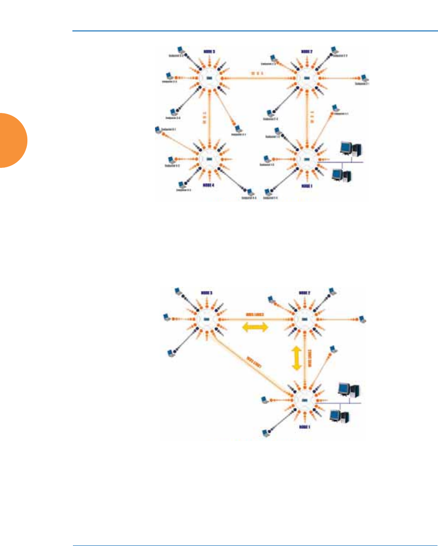
Wireless Access Point
64 Installing the Wireless AP
Figure 28. A Multiple Hop WDS Connection
z
Multiple WDS links can provide link redundancy (failover capability - see
Figure 29). A network protocol (Spanning Tree Protocol — STP) prevents
APs from forming network loops.
Figure 29. WDS Failover Protection

Wireless Access Point
Installing the Wireless AP 65
WDS links have a Host/Client relationship similar to the usual IAP/station
pattern for APs:
z
A WDS Client Link associates/authenticates to a host (target) AP in the
same way that stations associate to IAPs. The client side of the link must
be configured with the root MAC address of the target (host) AP.
z
A WDS Host Link acts like an IAP by allowing one WDS Client Link to
associate to it. An AP may have both client and host links.
WDS configuration is performed only on the client-side AP. See “WDS” on
page 385. Note that both APs must be configured with the same SSID name.

Wireless Access Point
66 Installing the Wireless AP
Common Deployment Options
The following table lists some typical and recommended deployment options for
a number of the features that have been discussed in this chapter.
See Also
Coverage and Capacity Planning
Network Management Planning
Planning Your Installation
Power Planning
Security Planning
Function Number of Wireless APs
One or Two Three or More
Power Power over Ethernet Power over Ethernet
UPS backup
(recommended)
Failover Recommended Highly recommended
VLANs Optional Optional use,
Can be used to put all APs
on one VLAN or map to
existing VLAN scheme
Encryption WPA2 with AES
(recommended)
PSK or 802.1x
WPA2 with AES
(recommended)
802.1x keying
Authentication Internal RADIUS server
EAP-PEAP
Pre-Shared Key
External RADIUS server
Management Cloud XMS or
Internal WMI
Internal CLI (via SSHv2)
Cloud XMS or
XMS (Enterprise-hosted)

Wireless Access Point
Installing the Wireless AP 67
Installation Workflow
This workflow illustrates the steps that are required to install and configure the
AP successfully. Review this flowchart before attempting to install the unit on a
customer’s network. Cloud XMS customers will skip the last two steps.
Figure 30. Installation Workflow
See Also
Coverage and Capacity Planning
Common Deployment Options
Determine the number of Arrays needed
Choose the location(s) for your Wireless Arrays
Install the mounting plate
Connect the cables and turn on the power
Verify that the Ethernet link and radio LEDs are functioning correctly
Review the Array Configuration
Run Ethernet cables for PoE
(<100m total distance from switch)
Log in to WMI

Wireless Access Point
68 Installing the Wireless AP
Failover Planning
Installation Prerequisites
Planning Your Installation
Power Planning
Wireless Access Point Product Overview
Security Planning
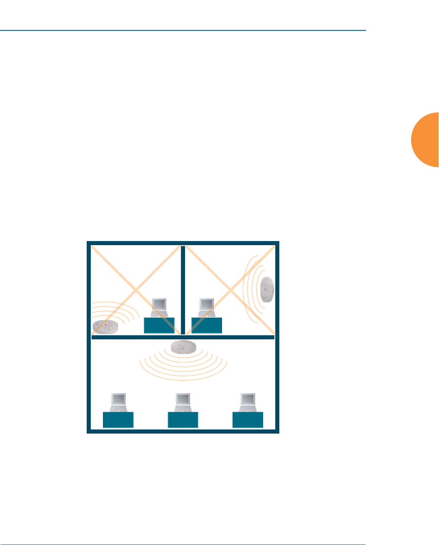
Wireless Access Point
Installing the Wireless AP 69
Installing Your Wireless AP
This section provides information about the physical installation of your Xirrus
Wireless AP. For complete instructions, please see the Installation Guide for your
model of AP or Access Point.
Choosing a Location
Based on coverage, capacity and deployment examples previously discussed,
choose a location for the AP that will provide the best results for your needs. The
Wireless AP was designed to be mounted on a ceiling where the unit is
unobtrusive and wireless transmissions can travel unimpeded throughout open
plan areas.
Choose a location that is central to your users (see the following diagram for
correct placement.
Figure 31. AP Placement
Wiring Considerations
Before using the Xirrus-supplied POE to distribute power, see “Power over
Ethernet (POE)” on page 16.
WR
ONG
CORRECT
R
ORRE
R
ORREC
WR
ONG
G
G
O
ON
R
O
R
ON
ON
R
O
R
ON

Wireless Access Point
70 Installing the Wireless AP
Once you have determined the best location for your Wireless AP, you must run
cables to the location for the following services:
Power
No separate power cable is required to the AP—Xirrus wireless APs use
POE (Power over Ethernet). See the Installation Guide for your AP model
for compatible power injectors or switches.
The total of all Cat 5e or Cat 6 cable segments from the Gigabit Ethernet
switch to the power injector and then to an AP POE port must be less
than 100m long. The AP must be connected to POE networks without
routing cabling to the outside plant, to ensure that cabling is not exposed
to lightning strikes or possible high voltage crossover.
Network
APs have at least one POE port to supply power and data over the same
cable. Many models have additional Gigabit ports, or even additional
POE ports. Please see the Installation Guide for your AP model for
detailed information about running cables to the AP and connecting it.
Some models also have a serial (console) port. The Serial cable may be up
to 25 feet long per the RS-232 specification.
#When the unit’s IP address is unknown or a network connection has not
been established, the serial cable is used for connecting directly with the
Command Line Interface (CLI) via HyperTerminal. When a network
connection is established, the AP can be managed from any of the available
network connections, either Gigabit 1 or Gigabit 2.
For models with no console port, such as the XR-500, XR-1000, and some
XR-2000 models, the Xircon utility may be used locally to set up an IP
address if necessary.

Wireless Access Point
Installing the Wireless AP 71
Important Note About Network Connections
See Also
Failover Planning
Installation Prerequisites
Installation Workflow
Mounting and Connecting the AP
Power over Ethernet (POE)
!The AP’s Ethernet ports should be plugged into an Ethernet switch, not an
Ethernet hub — if a hub is used, we recommend that you connect only one
Ethernet port.

Wireless Access Point
72 Installing the Wireless AP
Mounting and Connecting the AP
A detailed Installation Guide is available at support.xirrus.com that describes
mounting your AP. Please follow the provided instructions carefully. Data and
power connections to the AP are also detailed in the Installation Guide. Please
follow the cabling and connection instructions carefully.
Dismounting the AP
For all AP models, push up on the AP (i.e., push it against the mounting plate).
Then turn the AP to the left to remove it. This is similar to dismounting a smoke
detector.
Powering Up the Wireless AP
When powering up, the AP follows a specific sequence of LED patterns showing
the boot progress, and following a successful boot will provide extensive status
information.
Figure 32. LED Locations
AP LED settings may be altered or disabled entirely for diagnostic purposes or for
personal preference. Changes are made via the AP’s Command Line Interface or
the Web Management Interface — refer to “LED Settings” on page 380.
Ethernet Activity,
Status, and
Radio LEDs

Wireless Access Point
Installing the Wireless AP 73
AP LED Operating Sequences
Use the following tables to review the operating sequences of the AP’s LEDs.
z
“LED Boot Sequence” on page 73
z
“LED Operation when AP is Running” on page 74
LED Boot Sequence
The normal boot LED sequence is as follows:
AP Activity Status LED IAP LEDs
Power ON Blinking GREEN All OFF
Boot loader power ON
self-test
Blinking GREEN All ON
Image load from
compact FLASH
Blinking GREEN Spinning pattern (rotate all
to ON, then all to OFF)
Image load failure Blinking ORANGE All OFF
Hand off to ArrayOS Solid GREEN All OFF
System software
initialization
Solid GREEN Walking pattern — (LED
rotating one position per
second)
Up and running Solid GREEN ON for IAPs that are up:
OFF for IAPs that are down.
Green or orange per table on
the next page.
Behavior may be changed
using “LED Settings” on
page 380.

Wireless Access Point
74 Installing the Wireless AP
LED Operation when AP is Running
The normal LED operation when the AP is running is shown in the table below.
Note that behavior may be modified using “LED Settings” on page 380 or via the
CLI.
LED Status Reason
IAP LED is OFF IAP is down
IAP LED is solid ON IAP is up, but no associations and
no traffic
IAP LED heartbeat IAP is up, with stations associated
but no traffic
IAP LED flashing
Flashing at 10 Hz
Flashing at 5 Hz
Flashing at 2.5 Hz
IAP is up, passing traffic
Traffic > 1500 packets/sec
Traffic > 150 packets/sec
Traffic > 1 packet/sec
IAP LED is GREEN IAP is operating in the 2.4 GHz
band
IAP LED is ORANGE IAP is operating in the 5 GHz band
IAP LED flashing ORANGE to
GREEN at 1 Hz
The radio is in monitor mode
(standard intrude detect)
STATUS LED is GREEN *** AP is operational
GIG (Ethernet) LEDs are dual color
Ethernet LED is ORANGE
Ethernet LED is GREEN
Transferring data at 1 Gbps
Transferring data at 10/100 Mbps
*** NOTE: On an XR-2000 Series AP model ending in 5 or 6, there is a
combined GIG2/STS LED. If the GIG2 port is not connected, the LED behaves
as a Status LED. If the GIG2 port is connected, the LED behaves as a GIG2 LED.

Wireless Access Point
Installing the Wireless AP 75
See Also
Installation Prerequisites
Installation Workflow
Installing Your Wireless AP
LED Settings
Zero-Touch Provisioning and Ongoing Management
Most customers employ the Xirrus Management System (XMS) for the initial
setup and continuing management of Xirrus devices. XMS users can readily set
up their new devices for zero touch provisioning and ongoing maintenance via
the following platforms.
XMS-Cloud Next Generation (XMS-9500-CL-x)
XMS in the cloud performs zero touch provisioning as shown in this quick video
guide: www.xirrus.com/TV/Training/XMS-Cloud-Next-Generation. New APs
appear in XMS even before you receive your equipment. When the email arrives
with your login information, use XMS Cloud to specify the initial settings for your
APs. A Guided Tour will walk you through the basic steps of creating a profile
containing configuration settings, including creating SSIDs and firewall/
application control rules. Once a new, unlicensed AP is connected to a network
with DHCP and Internet connectivity, it will automatically contact Xirrus for
cloud-based zero touch provisioning per your settings. It will first install the latest
applicable license, and upgrade the AP to the latest software version as
appropriate.
XMS-Enterprise
(Also available as a cloud-deployed solution: XMS-9000-CL-x) This enterprise-
hosted platform automatically detects and provisions new Xirrus devices
deployed in your network via a zero touch provisioning approach similar to that
described above. Create and configure a default profile for newly added APs—
these new devices will automatically receive the configuration defined in your
default profile.

Wireless Access Point
76 Installing the Wireless AP
If you are not using XMS
If you are not using XMS, please proceed to the rest of this chapter to configure
your AP manually via the Express Setup menu option.
AP Management Interfaces
User Interfaces
With zero-touch setup provided by XMS, your Xirrus network is ready for use a
few minutes after deployment. We recommend that you use the XMS for ongoing
monitoring and fine-tuning of the network. (For XMS-E, you must set up a default
profile and discovery first, to find new APs).
To check the configuration of individual APs locally, AP settings may be viewed
or configured through the Command Line Interface (CLI) using SSH, or on a
browser with the Web Management Interface (WMI). You may use the CLI via the
serial management port (console—on all APs except the XR-500/600/1000 Series
and some XR-2000 models) or any of the Gigabit Ethernet ports. You can use the
WMI via any of the AP’s Ethernet ports.
Figure 33. Network Interface Ports—XR-520 (left); XR-1000 Series (right)
#If you are an XMS customer, we recommend that you manage your APs
completely by XMS. Wait five minutes after powering up the AP or Access
Point, then use XMS to view/manage this unit. If you change settings
directly on the AP, XMS may not sync up with these changes for up to 24
hours.
#Note that the AP must already be running ArrayOS release 6.5 or above to
support zero-touch provisioning.
Gigabit PoE (gig1)
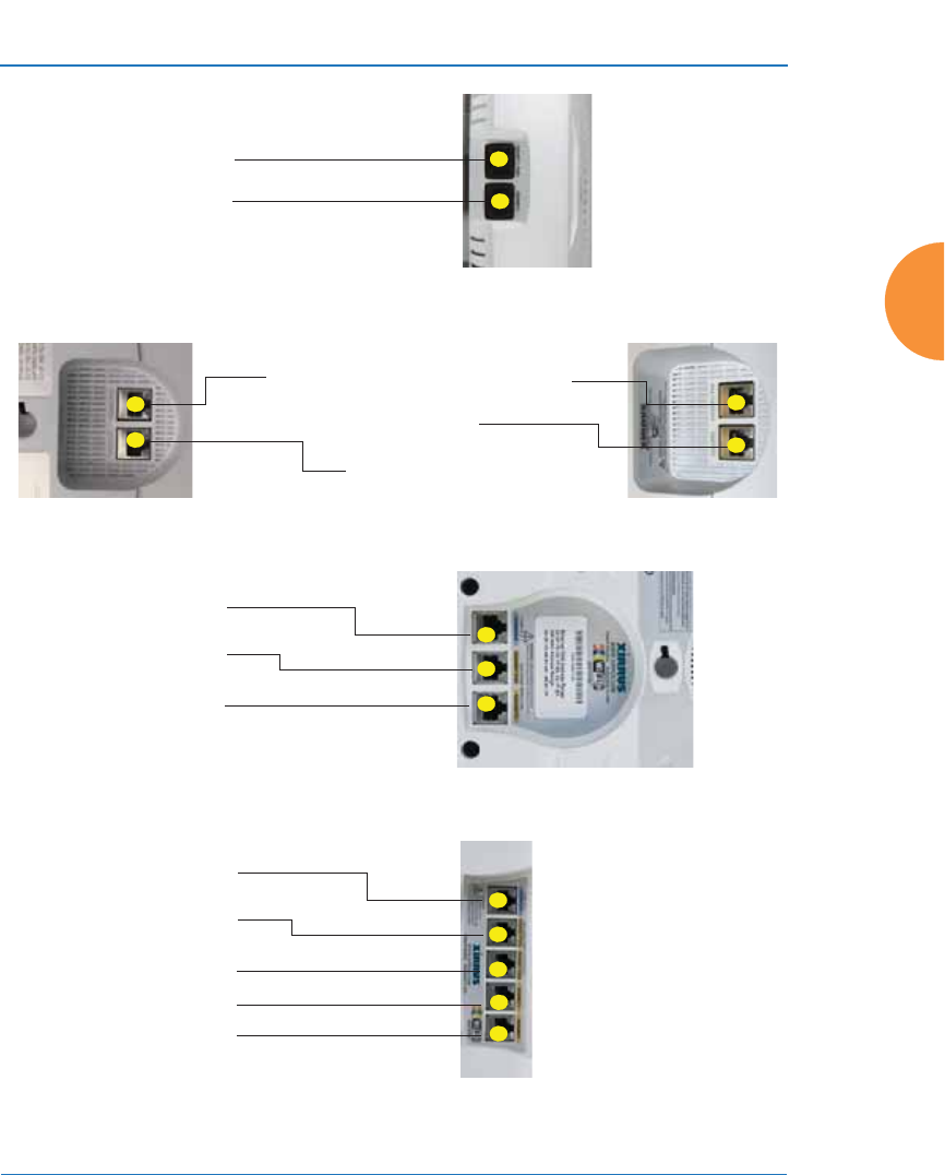
Wireless Access Point
Installing the Wireless AP 77
Figure 34. Network Interface Ports—XR-600 Series
Figure 35. Network Interfaces—XR-2000 Series (left); XR-2005/2006 (right)
Figure 36. Network Interface Ports—XR-4000 Series
Figure 37. Network Interface Ports—XR-6000 Series
Gigabit2 (gig2)
Gigabit1/PoE+ (gig1)
Gigabit1 PoE /Gigabit1 PoE+
Gigabit2
CONSOLE
Serial (Console)
Gigabit PoE (gig1)
Gigabit 2 (gig2)
Serial (Console)
Gigabit PoE1 (gig1)
Gigabit PoE2 (gig2)
Gigabit 3 (gig3)
Gigabit 4 (gig4)

Wireless Access Point
78 Installing the Wireless AP
Using the Serial Port
If using the serial port to make your connection, use serial settings of 8 bits, no
parity, no flow control, 1 stop bit (8N1) and a speed setting of 115200 baud. Use
the communication package of your choice. You may use the serial port to change
settings on the AP, even if the AP’s Gigabit interfaces are in XMS managed mode
(i.e., read-only mode, see “Managing APs Locally or Using XMS” on page 85).
Using the Ethernet Ports to Access the AP
By default, the AP's Ethernet interfaces use DHCP to obtain an IP address. If the
AP is booted and does not receive DHCP addresses on Gigabit Ethernet ports,
then both Gigabit1 and its bonded pair port (if any) will default to 10.0.2.1 with a
mask of 255.255.255.0.
If the AP is connected to a network that provides DHCP addresses, the IP address
can be determined by the following methods:
1. The simplest way to address the AP is using its default hostname which is
the AP’s serial number, found on the AP label and shipping container (for
example, XR40123091CACD). If your network provides DHCP and DNS,
then you can use this hostname.
2. Otherwise, examine the DHCP tables on the server and find the addresses
assigned to the AP (Xirrus MAC addresses begin with 00:0F:7D or
50:60:28 and are found on the AP label and shipping container).
3. Alternatively, you may query the AP using the CLI via the console port
(on all models except the XR-500/600/1000, and some XR-2000 models).
Log in using the default user name admin and password admin. Use the
show ethernet command to view the IP addresses assigned to each port.
#The Xircon utility may also be used to communicate with APs locally as an
alternative to using a serial connection to the console. This is especially
useful for the XR-500/600/1000 Series and some XR-2000 models, which do
not have a console port. See “Securing Low Level Access to the AP” on
page 81.

Wireless Access Point
Installing the Wireless AP 79
4. If the AP cannot obtain an IP address via DHCP, the factory default uses a
static IP address of 10.0.2.1 with a mask of 255.255.255.0 on its Gigabit
POE port.
To connect to the AP, you must set your laptop to be in the same subnet
as the AP: set your laptop’s IP address to be in the 10.0.2.xx subnet, and
set its subnet mask to 255.255.255.0. If this subnet is already in use on
your network, you may connect your laptop directly to the AP by
connecting the laptop to the power injector’s IN port temporarily (this
port may be called the SWITCH port or the DATA port on your injector).
Starting the WMI
Use this procedure to log in to the WMI on a Web browser.
1. Establish a network connection and open your Web browser.
2. Connect to the Wireless AP using its host name or IP address as described
in the previous section.
http://<hostname or IPaddress>
Logging In
Enter the default user name and password — the default user name is admin, and
the default password is admin.
See Also
Installation Workflow
Performing the Express Setup Procedure
Powering Up the Wireless AP
#Take care to ensure that your network is not using the 10.0.2.1 IP address
prior to connecting the AP to the network.

Wireless Access Point
80 Installing the Wireless AP
Licensing
When a newly deployed AP boots up, it automatically contacts Xirrus with its
serial number and MAC address and obtains its license key, software image, and
initial configuration from XMS. Any unlicensed AP running ArrayOS release 6.5
or above will update in this way after it boots up, if it has Internet connectivity
and if you are running XMS (you must have a default profile set up in XMS).
The AP’s license determines some of the features that are available on the AP. For
example, the Application Control feature on APs requires a license. When a new
AP first boots, it self-generates a license for its current software version. No
upgrades or licensed features will operate until the AP receives a license obtained
from Xirrus. The AP’s license is not installed at the factory.
If you need to enter the license manually, use the following procedure. It describes
entering the license key using the WMI. If you are using the XMS, you may use it
to manage and upgrade large numbers of licenses for the wireless network.
1. This procedure assumes that you have pointed a browser to the AP to
start WMI, and that you have logged in with the default username and
password above.
2. In the left hand frame, in the Configuration section, click Express Setup.
3. License Key: Enter the key License Activation Code (LAC) that was
provided for the AP. The key was provided to you in an email as an
attachment in the form of an Excel file (.xls). Enter the key exactly as it
appears in the file. Click the Apply button to apply the key.
4. Now you may verify the features provided by the key. In the Status
section of the left hand frame, click AP and then click Information. Check
the items listed in the License Features row.
Performing the Express Setup Procedure
The Express Setup procedure establishes global configuration settings that enable
basic AP functionality. Changes made in this window will affect all radios. If you
are not using XMS to perform your initial configuration, please see “Express

Wireless Access Point
Installing the Wireless AP 81
Setup” on page 163. Also see “Zero-Touch Provisioning and Ongoing
Management” on page 75.
See Also
Zero-Touch Provisioning and Ongoing Management
Installation Prerequisites
Installation Workflow
Logging In
Multiple SSIDs
Security
Securing Low Level Access to the AP
Most local management of the Xirrus AP is done via the WMI or CLI—see “The
Command Line Interface” on page 435. The AP also has a lower level interface:
XBL(Xirrus Boot Loader), which allows access to more primitive commands. You
won’t normally use XBL unless instructed to do so by Xirrus Customer Support.
For proper security, you should replace the default XBL login username and
password with your own, as instructed below. XBL has its own username and
password, separate from the ArrayOS Admin User and Password (used for
logging in to the WMI and CLI) that you may change on the Express Setup page
(see Step 5 on page 167).
Xirrus also provides the Xircon utility for connecting to Xirrus APs that are not
reachable via the normal access methods such as Secure Shell (SSH) or WMI and
that do not have a physical console port, or whose console port is not accessible.
Xircon discovers APs on your network subnet by sending IP/UDP broadcast
packets. Once an AP is discovered, Xircon can establish an encrypted console
session to the AP via the network even if the AP IP configuration is incorrect.
Xircon allows you to manage the AP using CLI, just as you would if connected to
the console port. Xircon also has an option for easily accessing XBL.
In normal circumstances Xirrus APs should be configured and managed through
SSH or via the WMI. A connection is established using either the AP hostname or
DHCP-assigned IP address, or via the other options described in “Using the
Ethernet Ports to Access the AP” on page 78. Xircon may be needed in special
circumstances as directed by Xirrus Customer Support for troubleshooting AP

Wireless Access Point
82 Installing the Wireless AP
problems or IP connectivity. (In this case, see the Xircon User Guide for detailed
information.)
Xircon access to the AP:
z
You may enable or disable all Xircon access to the AP as instructed in the
procedure below. There are also options to allow access only to CLI (i.e.,
ArrayOS access) or only to XBL.
z
Since some models do not have a console port, these models have Xircon
access to both XBL and CLI enabled by default. For APs that do not have
a console port, to avoid potentially being locked out of the AP, Xircon
should always be enabled at the XBL level at least.
z
On all other AP models (those with a console port), Xircon access to both
XBL and CLI is disabled by default. If Xircon is not going to be used to
access an AP, we recommend leaving Xircon access disabled.
Procedure for Securing Low Level AP Access
Use the following steps to replace the default XBL username and password, and
optionally to change the type of Xircon management access that is allowed. These
steps use CLI commands.
1. To access CLI via the WMI, click CLI under the Tools section on the left
(for detailed instructions see “CLI” on page 426). Skip to Step 4 on
page 83.
To access CLI via SSH, see “Establishing a Secure Shell (SSH)
Connection” on page 435. Then proceed to the next step.
!If you disable Xircon access to both XBL and CLI on models with no console
port, you must ensure that you do not lose track of the username and password
to log in to CLI/WMI! In this situation, there is no way to recover from a lost
password, other than returning the AP to Xirrus. If you have Xircon access to
XBL enabled, you can reset the password, but this recovery will require setting
the unit to factory defaults with loss of all configuration data.

Wireless Access Point
Installing the Wireless AP 83
2. At the login as prompt, log in to CLI using the username and password
that you set in Step 5 on page 167, or the default value of admin/admin if
you have not changed them.
login as: jsmith
jsmith@xr4012802207c's password:
Xirrus Wi-Fi AP
ArrayOS Version 6.1.2-3299
Copyright (c) 2005-2012 Xirrus, Inc.
http://www.xirrus.com
AP42#
3. Type configure to enter the CLI config mode.
AP42#configure
4. If Xircon access at the XBL level is to be allowed, use the following three
commands to change the XBL username and password from the default
values of admin/admin. In the example below, replace newusername
and newpassword with your desired entries. Note that these entries are
case-sensitive.
AP42#(config)#boot-env
AP42#(config-boot)#set username newusername
AP42#(config-boot)#set password newpassword
AP42#(config-boot)#save
Saving boot environment .... OK
AP42(config-boot)# exit
5. Enter the following commands if you wish to change Xircon access
permission:
AP42#(config)# management
AP42#(config-mgmt)# xircon <management-status>
AP42#(config-mgmt)# save
AP42#(config-mgmt)# exit
AP42#(config)#
<management-status> may be one of:
z
on—enables both CLI and XBL access
z
off—disables both CLI and XBL access
z
aos-only—enables only CLI (i.e. ArrayOS) access

Wireless Access Point
84 Installing the Wireless AP
z
boot-only—enables only XBL access
Note that there is a WMI setting for changing Xircon access, timeout
period, and the UDP port used. This may be used instead of CLI if you
wish. See “Management Control” on page 238. Note that you cannot
change the XBL username and password via the WMI.

Wireless Access Point
The Web Management Interface 85
The Web Management Interface
This topic provides an overview of the Xirrus Wireless AP’s embedded Web
Management Interface (WMI), used for establishing your network’s configuration
settings and wireless operating parameters. It also includes login instructions.
The following topics are discussed:
z
Managing APs Locally or Using XMS
z
An Overview
z
Structure of the WMI
z
User Interface
z
Logging In
z
Applying Configuration Changes
Managing APs Locally or Using XMS
For Xirrus deployments of any size, we recommend that you use XMS to manage
the network rather than directly managing each AP individually. You may change
settings directly on the AP—but be aware that XMS may not sync up with these
changes for up to 24 hours. All XMS versions automatically “rediscover” the
wireless network once a day by default, and XMS will fetch updated settings into
its database at that time. If you are an XMS-Cloud customer (XMS-9500-CL-x),
you may wish to use WMI or CLI directly on the wireless device to change
settings that may not be available in XMS-Cloud.
To immediately sync up XMS with changes that you have made to a particular
AP, you may go to the XMS Monitor > APs or Configure > APs page. Select the
AP, and click the Refresh button to update XMS with your changes on an AP.
This causes XMS to read the current configuration of the AP and update the XMS
database with these values.
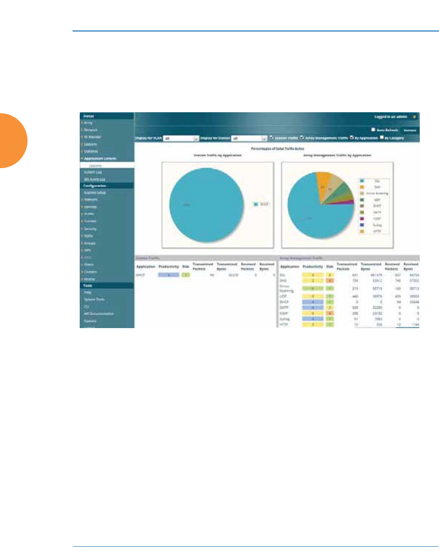
Wireless Access Point
86 The Web Management Interface
An Overview
The WMI is an easy-to-use graphical interface to your Wireless AP. It allows you
to configure the product to suit your individual requirements and ensure that the
unit functions efficiently and effectively.
Figure 38. Web Management Interface

Wireless Access Point
The Web Management Interface 87
Structure of the WMI
The content of the WMI is organized by function and hierarchy, shown in the
following table. Click on any item below to jump to the referenced destination.
Status Windows
Access Point Status Windows
Access Point Summary
Access Point Information
Access Point Configuration
Admin History
Network Status Windows
Network Map
Spanning Tree Status
Routing Table
ARP Table
DHCP Leases
Connection Tracking/NAT
CDP List
Network Assurance
RF Monitor Windows
IAP Monitoring
Spectrum Analyzer
Rogues
Channel History
Radio Assurance
Station Status Windows
Stations
Location Map
RSSI
Signal-to-Noise Ratio (SNR)
Noise Floor
Max by IAP
Station Assurance
Statistics Windows
IAP Statistics Summary
Per-IAP Statistics
Network Statistics
VLAN Statistics
WDS Statistics
IDS Statistics
Filter Statistics
Station Statistics
Per-Station Statistics
Application Control Windows
System Log Window
IDS Event Log Window

Wireless Access Point
88 The Web Management Interface
Configuration Windows
Express Setup
Network
Interfaces
Bonds and Bridging
DNS Settings
Cisco Discovery Protocol
(CDP) Settings
Services
Time Settings (NTP)
NetFlow
Wi-Fi Tag
Location
System Log
SNMP
DHCP Server
Proxy Services
VLANs
VLAN Management
Tunnels
Tunnel Management
SSID Assignments
Security
Admin Management
Admin Privileges
Admin RADIUS
Management Control
Access Control List
Global Settings
External Radius
Internal Radius
Active Directory
Rogue Control List
OAuth 2.0 Management
SSIDs
SSID Management
Active IAPs
Per-SSID Access Control List
Honeypots
Configuration Windows (cont’d)
Groups
Group Management
IAPs
IAP Settings
Global Settings
Global Settings .11an
Global Settings .11bgn
Global Settings .11n
Global Settings .11u
Global Settings .11ac
Advanced RF Settings
Hotspot 2.0
NAI Realms
NAI EAP
Intrusion Detection
LED Settings
DSCP Mappings
Roaming Assist
WDS
WDS Client Links
Filters
Filter Lists
Filter Management
Clusters
Cluster Management
Mobile
AirWatch
Tool Windows
System Tools
CLI
API Documentation
Options
Logout
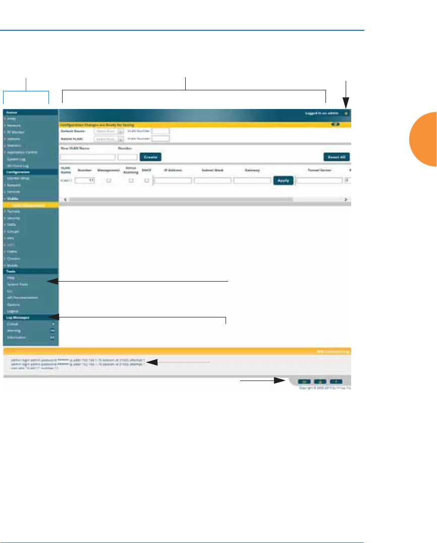
Wireless Access Point
The Web Management Interface 89
User Interface
Figure 39. WMI: Frames
The WMI has been designed with simplicity in mind, making navigation quick
and easy. In the following example, you’ll see that windows are divided into left
and right frames. (Figure 39 )
The left frame contains two main elements:
z
The menu is organized into three major sections (Status, Configuration,
Tools). Each has headings for major functions, such as Network, SSIDs,
Security, etc. Click a heading, such as Network, to display a page
Left frame Right frame Utilities
Log Message counters
Help
Command log
Utilities

Wireless Access Point
90 The Web Management Interface
showing a summary of its current configuration, as well as to show links
for all of its associated WMI pages.
z
Three Log Messages counters are located at the bottom of the menu. They
provide a running total of messages generated by the ArrayOS Syslog
subsystem during your session — organized into Critical, Warning, and
General messages. Click on a counter to display the associated Syslog
messages. Messages at the selected level or higher will be shown. For
more information, please see “System Log Window” on page 157.
The right frame has four main elements:
z
The header shows the AP type in the upper right corner, along with the
hostname (this defaults to the unit’s serial number) and IP address. The
Uptime shows the time since the AP was last rebooted.
Below this is the page title, and the user name you used to log in. On the
right, click the Utilities button for a drop-down menu that allows
you to Refresh Page, Save your changes, open the Help system, or
Logout. If you have any unsaved changes, the Save button is
displayed on the right, in the top bar.
Figure 40. WMI Header
z
The main window displays the status information or configuration page
that you requested. This is where you review the AP’s current status and
activity or enter changes if you wish.
#If you have added modular IAPs to your AP, note that its model number will
be automatically adjusted to reflect the count and types of IAPs currently
installed. See Upgrading with 802.11ac radio modules.
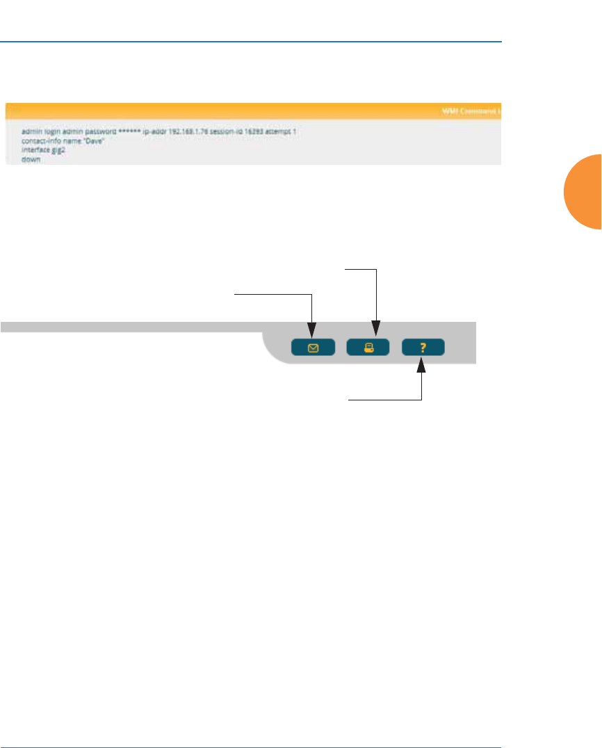
Wireless Access Point
The Web Management Interface 91
z
The Command Log shows the resulting commands for requests made
through the WMI.
Figure 41. WMI Command Log
z
Utility buttons are located at the bottom right of each window — a
Feedback button, a Print button and a Help button.
Figure 42. WMI: Utility Buttons
z
Click the Feedback button to generate a Web page that allows you to
submit your comments to Xirrus, Inc.
z
Click the Print button to open a print dialog to send a copy of the active
window to your local printer.
z
Click the Help button to access the AP’s online help system.
Submitting Your Comments
When submitting comments via the Feedback button ensure that you provide as
much detail as possible, including your contact information, the product model
number that the comment relates to, and the ArrayOS software version (if
known). When finished, click on the Submit button to submit your comment.
Print button
Help button
Feedback button

Wireless Access Point
92 The Web Management Interface
Note that WMI provides an option that allows you to change its behavior. You
may change:
z
Refresh Interval — the refresh interval, if automatic refresh is selected.
See “Options” on page 433 for more information.
Logging In
Use this procedure to log in to the WMI via your Web browser.
1. Establish a network connection and open your Web browser.
2. If your network supports DHCP and DNS, enter the AP’s default host
name in the browser’s URL. The default host name is simply the AP’s
serial number (for example, XR0823091CACD).
Otherwise, enter the AP’s IP address. This may be determined as
described in “Using the Ethernet Ports to Access the AP” on page 78.
3. The default login to the AP’s Web Management Interface is admin for
both the user name and password.
Figure 43. Logging In to the Wireless AP
#Some pages or individual settings are only available if the AP’s license
includes appropriate Xirrus Advanced Feature Sets. If a setting is
unavailable (grayed out), then your license does not support the feature. See
“About Licensing and Upgrades” on page 412.

Wireless Access Point
The Web Management Interface 93
Applying Configuration Changes
In most of the WMI configuration windows, your changes to settings are applied
to the AP as you make them. In most cases, there is no separate Apply button to
click to make the changes take effect. There are a few exceptions to this rule. In
these cases, a particular section of a page may have its own Apply Settings
button right below the settings.
In both cases described above, the changes that you have made are not saved to
the latest configuration file in the AP’s flash memory, so they will not be restored
after a reboot. Click the Save button (located on the upper right of each page)
in order to make sure that these changes will be applied after rebooting. This will
save the entire current configuration, not only the changes on current WMI page.
Character Restrictions
When inputting strings in the WMI (for example, assigning SSIDs, host name,
password, etc.), use common alphanumeric characters. Some of the fields in the
WMI will not accept special characters, so use of the following characters should
typically be avoided:
&<>' “ / \

Wireless Access Point
94 The Web Management Interface

Wireless Access Point
Viewing Status on the Wireless AP 95
Viewing Status on the Wireless
AP
These windows provide status information and statistics for your AP using the
product’s embedded Web Management Interface (WMI). You cannot make
configuration changes to your AP from these windows. The following topics have
been organized into functional areas that reflect the flow and content of the Status
section of the navigation tree in the left frame of the WMI.
z
“Access Point Status Windows” on page 96
z
“Network Status Windows” on page 104
z
“RF Monitor Windows” on page 115
z
“Station Status Windows” on page 126
z
“Statistics Windows” on page 139
z
“Application Control Windows” on page 150
z
“System Log Window” on page 157
z
“IDS Event Log Window” on page 158
Configuration and Tools windows are not discussed here. For information on
these windows, please see:
z
“Configuring the Wireless AP” on page 161
z
“Using Tools on the Wireless AP” on page 411
#If you have added modular IAPs to your AP, note that its model number will
be automatically adjusted to reflect the count and types of IAPs currently
installed. See Upgrading with 802.11ac radio modules.
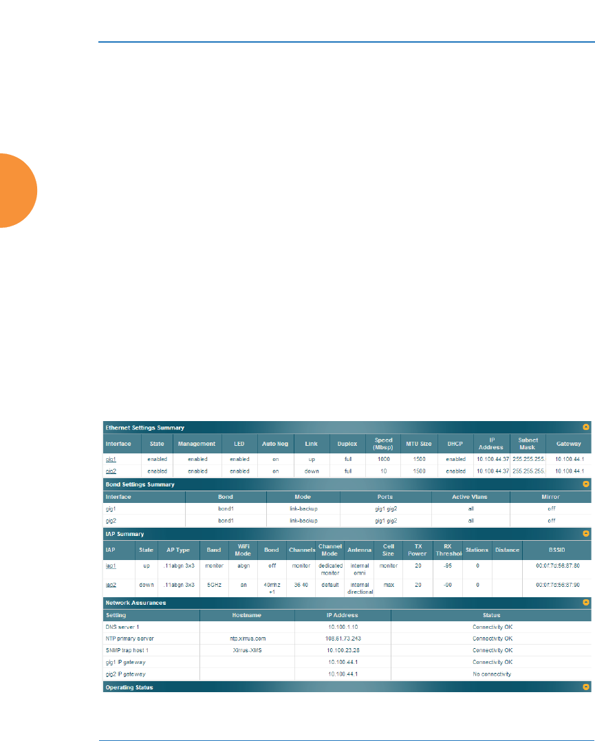
Wireless Access Point
96 Viewing Status on the Wireless AP
Access Point Status Windows
The following AP Status windows are available:
z
Access Point Summary — displays information on the configuration of all
AP interfaces, including IAPs.
z
Access Point Information — provides version/serial number information
for all AP components.
z
Access Point Configuration — shows all configuration information for
the AP in text format.
z
Admin History — shows all current and past logins since the last reboot.
Access Point Summary
This is a status only window that provides a snapshot of the global configuration
settings for all Wireless AP network interfaces and IAPs. You must go to the
appropriate configuration window to make changes to any of the settings
displayed here — configuration changes cannot be made from this window.
Clicking on an interface or IAP will take you to the proper window for making
configuration changes.
Figure 44. AP Summary

Wireless Access Point
Viewing Status on the Wireless AP 97
Content of the Access Point Summary Window
The Access Point Summary window is sub-divided into the Ethernet Interfaces
section and the Integrated Access Point (radio) section, providing you with the
following information:
z
Ethernet Settings Summary
This section provides information about network interface devices. To
make configuration changes to these devices, go to “Interfaces” on
page 170.
•Interface: Lists the network interfaces that are available on the AP.
•State: Shows the current state of each interface, either enabled or
disabled.
•Mgmt: Shows whether AP management traffic is allowed on this
interface.
•Auto Neg: Shows whether auto-negotiation is in use on this interface,
to determine settings for speed, parity bits, etc.
•LED: Shows whether LED display of interface status is enabled.
•Link: Shows whether the link on this interface is up or down.
•Duplex: Shows whether full duplex mode is in use.
•Speed: Shows the speed of this interface in Mbps.
•MTU Size: Shows the Maximum Transmission Unit size that has
been configured. This is the largest packet size (in bytes) that the
interface can pass along.
•DHCP: Shows whether DHCP on this port is enabled or disabled.
•IP Address: Shows the current IP address assigned to each network
interface device.
•Subnet Mask: Shows the subnet mask, which defines the number of
IP addresses that are available on the routed subnet where the AP is
located.
•Gateway: Shows the IP address of the router that the AP uses to
transmit data to other networks.

Wireless Access Point
98 Viewing Status on the Wireless AP
z
Bond Settings Summary
This section provides information about the relationship that has been
selected for the Gigabit ports. For detailed explanations and to make
configuration changes, see “Bonds and Bridging” on page 173.
•Bond: Lists all network bonds that have been configured.
•Mode: Shows the type of relationship that has been selected for the
Gigabit ports.
•Ports: Shows the Gigabit ports that are part of this bond.
•Port Mode: Shows the relationship that has been selected for the
Ethernet ports. See “Bonds and Bridging” on page 173 for details
•Active VLANs: Shows the VLANs that are active in this bond.
•Mirror: Shows whether mirroring is enabled on this bond.
z
IAP Section
This section provides information about the Integrated Access Points
(IAPs) that are contained within the AP. How many IAPs are listed
depends on which product model you are using. To make configuration
changes to these IAPs, go to “IAP Settings” on page 313.
•IAP: Lists the IAPs that are available on the AP.
•State: Shows the current state of each IAP, either up or down. IAPs
that are down are shown in RED. Figure 45 shows an example where
iap7 is down.
•AP Type: Shows the types of 802.11 clients supported by this IAP (11/
a/b/g/n) and the number of separate data streams transmitted and
received by the antennas of each IAP for 802.11n. For example, 3x3
means that the IAP supports three transmit chains and three receive
chains. See “Up to Eight Simultaneous Data Streams — Spatial
Multiplexing” on page 44.

Wireless Access Point
Viewing Status on the Wireless AP 99
Figure 45. Disabled IAP (Partial View)
•Channel: Shows which channel each IAP is using, and the channel
setting. To avoid co-channel interference, adjacent radios should not
be using adjacent channels. To make channel selections for a specific
IAP, go to “IAP Settings” on page 313.
•Wi-Fi Mode: Shows the 802.11 client types that the IAP has been
configured to support.
•Antenna: Shows which antenna is being used by each IAP.
•Cell Size: Indicates which cell size setting is currently active for each
IAP — small, medium, large, max, automatic, or manually defined by
you.
Figure 46. IAP Cells
The cell size of an IAP is a function of its transmit power and
determines the IAP’s overall coverage. To define cell sizes, go to “IAP
Settings” on page 313. For additional information about cell sizes and
the importance of planning for and defining the optimum cell sizes
for your AP, go to “Coverage and Capacity Planning” on page 34.
•Tx Power: Shows the transmit power for each IAP.
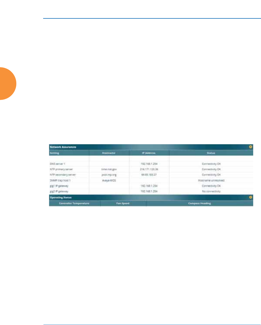
Wireless Access Point
100 Viewing Status on the Wireless AP
•Rx Threshold: Shows the receive threshold for each IAP.
•Stations: Informs you how many client stations are currently
associated with each IAP.
•WDS Link/Distance: The WDS Link on this radio (if any), and
whether the link has been set to support Long Distance Links. See
“WDS” on page 385.
•MAC Address/BSSID: Shows the MAC address for each IAP.
•Description: The description (if any) that you set for this IAP.
z
Network Assurance Section
This section shows the results of ongoing network assurance testing. This
is the same as information shown in “Network Assurance” on page 113.
Figure 47. Network Assurance and Operating Status
The AP checks connectivity to network servers that you have configured
(for example, DNS and NTP servers) on an ongoing basis. For each
Setting, this list shows the server’s Host Name (if any), IP Address, and
Status.
Network assurance must be enabled on the AP in order to perform these
connectivity tests and display this information. See “Management
Control” on page 238.
z
Operating Status Section
This section shows the AP controller board’s current internal
temperatures, current fan speed, and compass heading. (Figure 47)

Wireless Access Point
Viewing Status on the Wireless AP 101
Notice that the Compass Heading field will only show a value if the AP
model is one that includes a built-in compass. In order for this reading to
be correct, the AP must be mounted with iap1 facing north. If the AP does
not have an integrated compass, this field will just show a dash.
See Also
Management Control
Interfaces
Bonds and Bridging
IAP Settings
Network Assurance
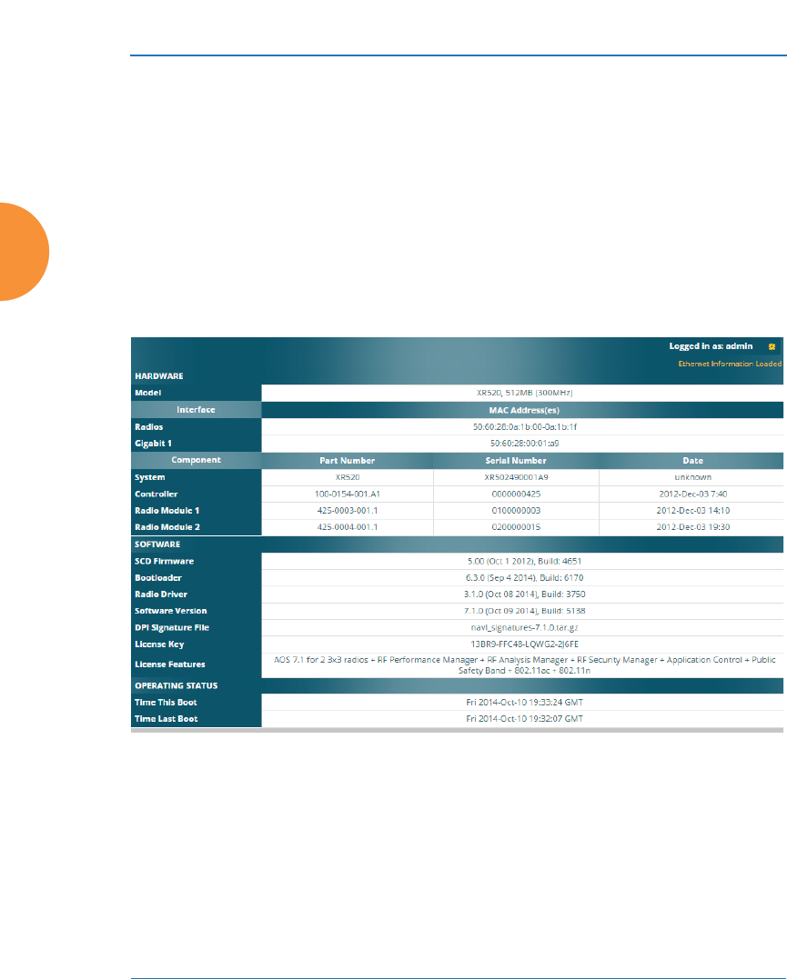
Wireless Access Point
102 Viewing Status on the Wireless AP
Access Point Information
This is a status only window that shows you the current firmware versions
utilized by the AP, serial numbers assigned to each module, MAC addresses,
licensing information, and recent boot timestamps. It will also show current
internal temperatures, fan speed, and compass heading if the AP model supports
these features.
Notice that the License Features row lists the features that are supported by your
AP’s license. See “About Licensing and Upgrades” on page 412 and “Advanced
Feature Sets” on page 21 for more information.
Figure 48. AP Information
You cannot make configuration changes in this window, but if you are
experiencing issues with network services, you may want to print the content of
this window for your records.
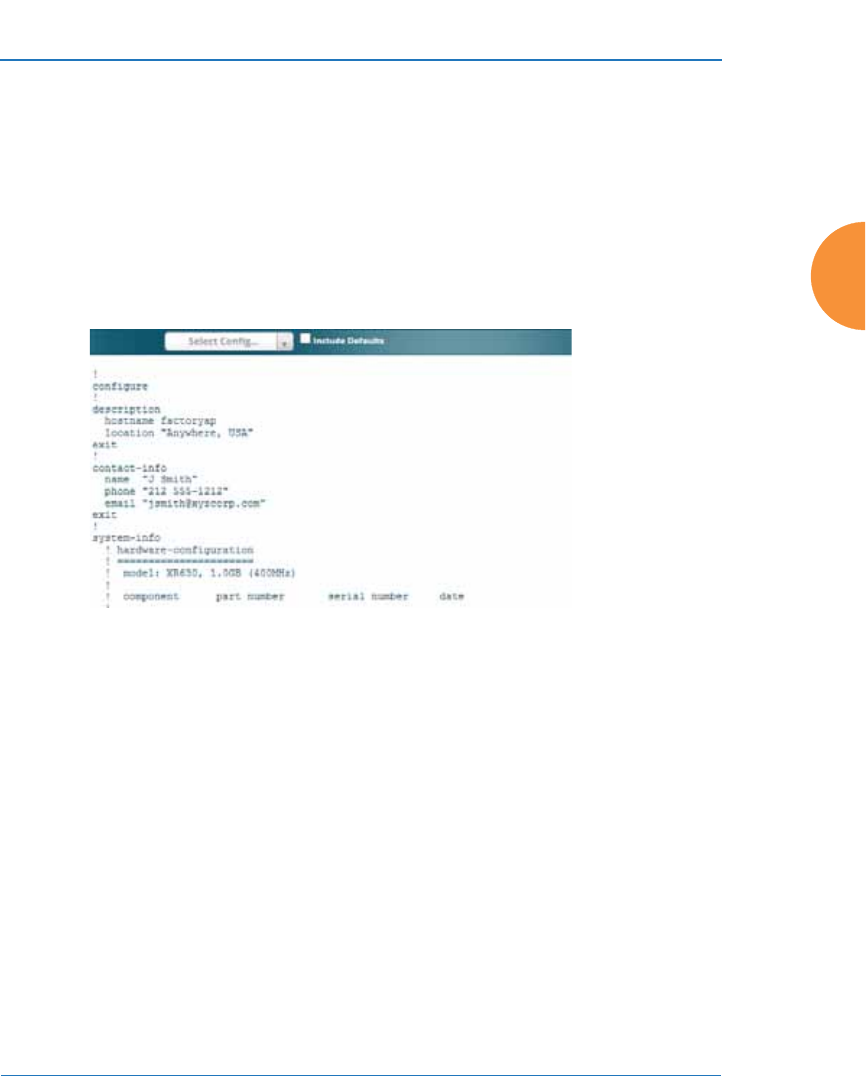
Wireless Access Point
Viewing Status on the Wireless AP 103
Access Point Configuration
This is a status only window that allows you to display the configuration settings
assigned to the AP, based on the following filter options:
z
Running — displays the current configuration (the one running now).
z
Saved — displays the saved configuration from this session.
z
Lastboot — displays the configuration as it was after the last reboot.
z
Factory — displays the configuration established at the factory.
Figure 49. Show Configuration
If you want to see just the differences between the Running, Saved, Lastboot, and
Factory configurations, you can do this by choosing a configuration option from
the Select Config pull-down menu then selecting an alternative configuration
option from the Select Diff pull-down menu.
To include the default configuration settings in the output, choose the
configuration then click the Include Defaults check box. If Include Defaults is
disabled, then only the changes from the default configuration are shown.
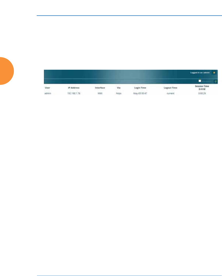
Wireless Access Point
104 Viewing Status on the Wireless AP
Admin History
It is useful to know who else is currently logged in to an AP while you're
configuring it, or who has logged in since the AP booted. This status-only
window shows you all administrator logins to the AP that have occurred since the
last reboot. To determine who is currently logged in, check which entries say
active in the Logout Time column.
Figure 50. Admin Login History
Network Status Windows
The following Network Status windows are available:
z
Network — displays a summary of network interface settings.
z
Network Map — displays information about this AP and neighboring
APs that have been detected.
z
Spanning Tree Status — displays the spanning tree status of network
links on this AP.
z
Routing Table — displays information about routing on this AP.
z
ARP Table — displays information about Address Resolution Protocol on
this AP.
z
DHCP Leases — displays information about IP addresses (leases) that the
AP has allocated to client stations.
z
Connection Tracking/NAT — lists connections that have been established
for client stations.
z
CDP List — lists neighboring network devices using Cisco Discovery
Protocol.
z
LLDP List — lists devices on the AP’s network that support the Link
Layer Discovery Protocol (LLDP).
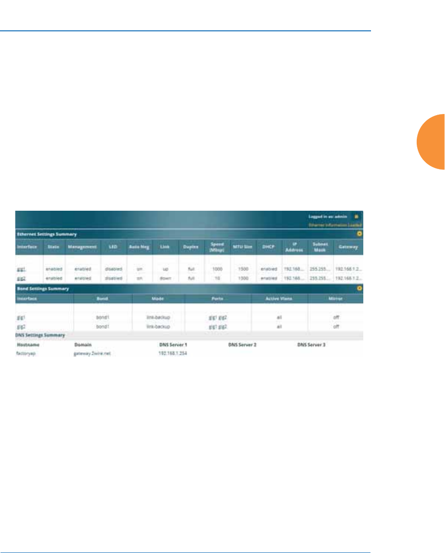
Wireless Access Point
Viewing Status on the Wireless AP 105
z
Network Assurance — shows results of connectivity tests for network
servers.
z
Undefined VLANs — shows VLANs present on an 802.1Q connection to
the AP, that are not configured in the AP's VLAN list.
Network
This window provides a snapshot of the configuration settings currently
established for AP’s wired interfaces. This includes the Gigabit interfaces and
their bonding settings. DNS Settings are summarized as well. You can click on
any item in the Interface or Bond columns to go to the associated configuration
window.
Figure 51. Network Settings
WMI windows that allow you to change or view configuration settings associated
with the network interfaces include:
z
“Interfaces” on page 170
z
“Bonds and Bridging” on page 173
z
“DNS Settings” on page 180
z
“Cisco Discovery Protocol (CDP) Settings” on page 181
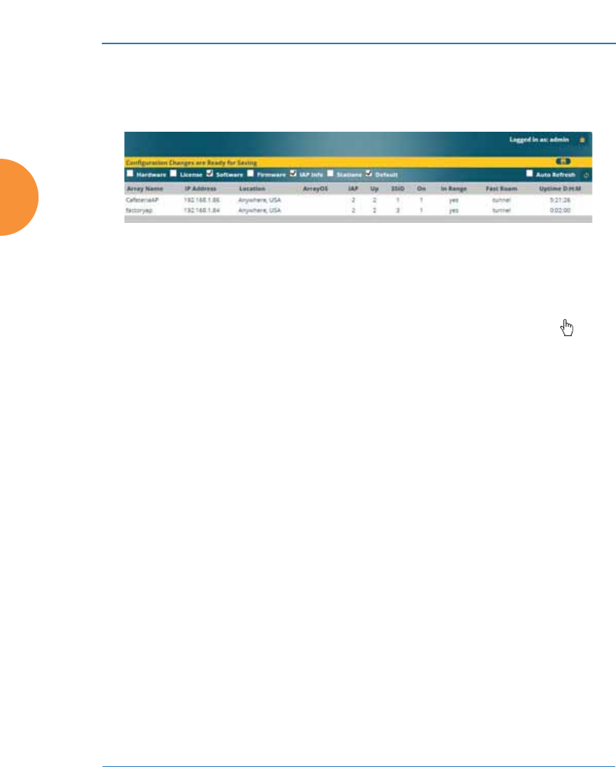
Wireless Access Point
106 Viewing Status on the Wireless AP
Network Map
This window offers detailed information about this AP and all neighboring APs,
including how the APs have been set up within your network.
Figure 52. Network Map
The Network Map has a number of options at the top of the page that allow you
to customize your output by selecting from a variety of information that may be
displayed. You may sort the rows based on any column that has an active column
header, indicated when the mouse pointer changes to the hand icon . Click
Refresh to update the information at any time. Click Auto Refresh to instruct the
AP to refresh this window automatically.
Content of the Network Map Window
By default, the network map shows the following status information for each AP:
z
Access Point Name: The host name assigned to the AP. To establish the
host name, go to “Express Setup” on page 163. You may click the host
name to access WMI for this AP.
z
IP Address: The AP’s IP address. You may click the address to access
WMI for this AP. If DHCP is enabled, the AP’s IP address is assigned by
the DHCP server. If DHCP is disabled, you must assign a static IP
address. To enable DHCP or to assign a static IP address for the AP, go to
“Express Setup” on page 163.
z
Location: The location assigned to the AP. To establish the location
information, go to “Express Setup” on page 163.
z
Array OS: The software version running on the AP.
z
IAP: The number of IAPs on the AP.

Wireless Access Point
Viewing Status on the Wireless AP 107
z
(IAP) Up: Informs you how many IAPs are currently up and running. To
enable or disable all IAPs, go to “Express Setup” on page 163. To enable
or disable individual IAPs, go to “IAP Settings” on page 313.
z
SSID: Informs you how many SSIDs have been assigned for the AP. To
assign an SSID, go to “SSID Management” on page 277.
z
(SSID) On: Informs you how many SSIDs are enabled. To enable or
disable SSIDs, go to “SSID Management” on page 277.
z
In Range: Informs you whether the AP is within wireless range of
another Wireless AP.
z
Fast Roam: Informs you whether or not the Xirrus fast roaming feature is
enabled. This feature utilizes the Xirrus Roaming Protocol (XRP) ensuring
fast and seamless roaming capabilities between IAPs or APs at both Layer
2 and Layer 3. To enable or disable fast roaming, go to “Global Settings”
on page 319.
z
Uptime (D:H:M): Informs you how long the AP has been up and running
(in Days, Hours and Minutes).
To see additional information, select from the following checkboxes at the bottom
of the page. This will show the columns described below.
Hardware
z
Model: The model number of each AP, plus the amount of RAM memory
and the speed of the processor.
z
Serial: Displays the serial number of each AP.
License
z
License: The license key of each AP.
z
Licensed Features: Lists the features enabled by the key.
Software (enabled by default)
z
Enable/disable display of the AP OS column.
Firmware
z
Boot Loader: The software version number of the boot loader on each AP.

Wireless Access Point
108 Viewing Status on the Wireless AP
z
SCD Firmware: The software version number of the SCD firmware on
each AP.
IAP Info (enabled by default)
z
Enable/disable display of the IAP/Up columns.
Stations
z
Stations: Tells you how many stations are currently associated to each
AP. To de-authenticate a station, go to “Stations” on page 127.
The columns to the right (H, D, W, and M) show the highest number of
stations that have been associated over various periods of time: the
previous hour, day, week, and month.
Default
z
Sets the columns displayed to the default settings. By default, only
Software and IAP Info are selected.
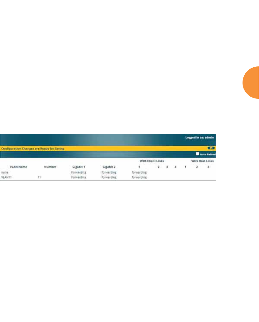
Wireless Access Point
Viewing Status on the Wireless AP 109
Spanning Tree Status
Multiple active paths between stations can cause loops in the network. If a loop
exists in the network topology, the potential exists for the duplication of
messages. The spanning tree protocol is a link management protocol that
provides path redundancy while preventing undesirable loops. For a wireless
network to function properly, only one active path can exist between two stations.
To facilitate path redundancy, the spanning tree protocol defines a tree that spans
all stations in the network and forces certain redundant data paths into a standby
(blocked) state. If one segment in the spanning tree becomes unreachable, the
spanning tree algorithm reconfigures the network topology and reestablishes the
link by activating the standby path. The spanning tree function is transparent to
client stations.
Figure 53. Spanning Tree Status
This window shows the spanning tree status (forwarding or blocked) for path
segments that terminate on the Gigabit ports and WDS links of this AP. You may
sort the rows based on the VLAN Name or Number columns by clicking the
column header. Click Refresh to update the information at any time. Click Auto
Refresh to instruct the AP to refresh this window automatically.
See Also
Network
Interfaces
Network Status Windows
VLANs
WDS
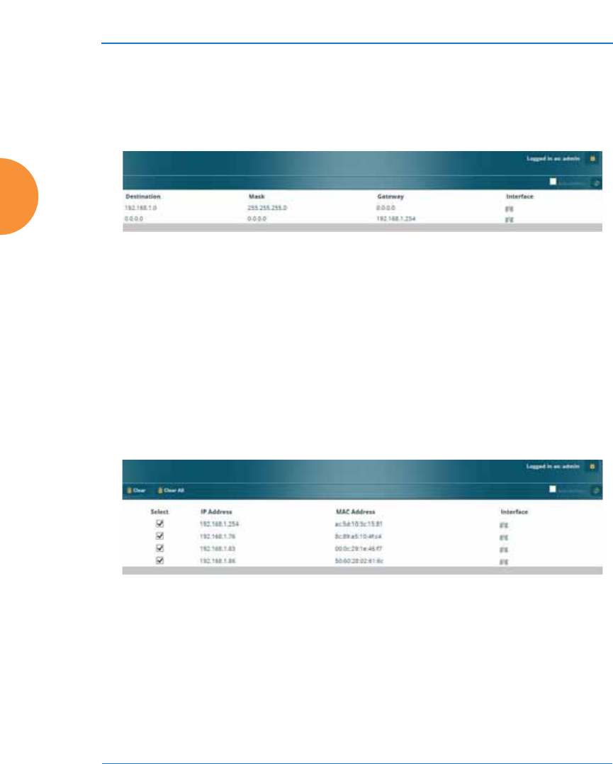
Wireless Access Point
110 Viewing Status on the Wireless AP
Routing Table
This status-only window lists the entries in the AP’s routing table. The table
provides the AP with instructions for sending each packet to its next hop on its
route across the network.
Figure 54. Routing Table
See Also
VLANs
Configuring VLANs on an Open SSID
ARP Table
This status-only window lists the entries in the AP’s ARP table. For a device with
a given IP address, this table lists the device’s MAC address. It also shows the AP
interface through which this device may be reached. The table typically includes
devices that are on the same local area network segment as the AP.
Figure 55. ARP Table
See Also
Routing Table
ARP Filtering
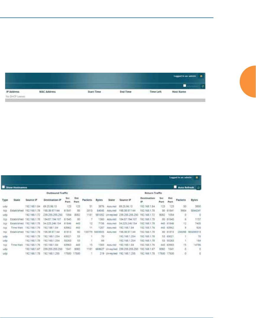
Wireless Access Point
Viewing Status on the Wireless AP 111
DHCP Leases
This status-only window lists the IP addresses (leases) that the AP has allocated to
client stations. For each, it shows the IP address assigned from one of the defined
DHCP pools, and the MAC address and host name of the client station. The start
and end time of the lease show how long the allocation is valid. The same IP
address is normally renewed at the expiration of the current lease.
Figure 56. DHCP Leases
See Also
DHCP Server
Connection Tracking/NAT
This status-only window lists the session connections that have been created on
behalf of clients. This table may also be used to view information about current
NAT sessions.
Figure 57. Connection Tracking
Click the Show Hostnames checkbox at the top of the page to display name
information (if any) for the source and destination location of the connection. The
Hostname columns will replace traffic statistics columns.
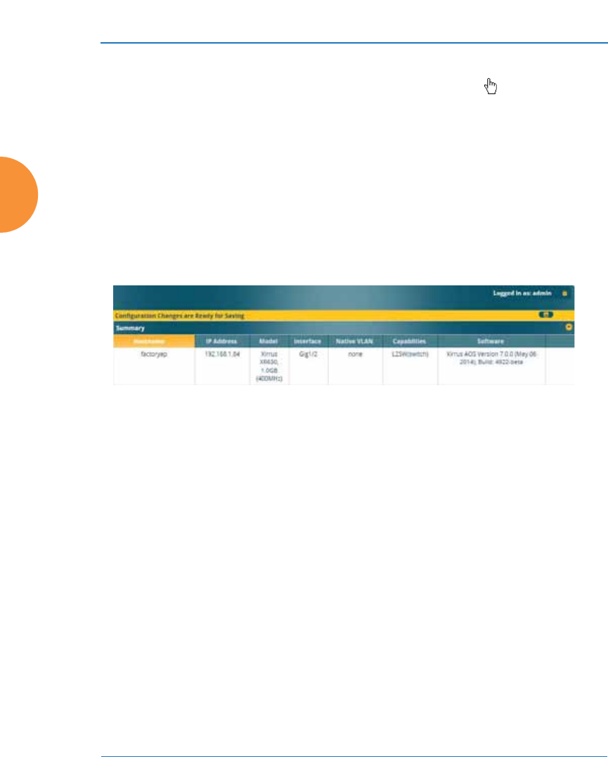
Wireless Access Point
112 Viewing Status on the Wireless AP
You may sort the rows based on any column that has an active column header,
indicated when the mouse pointer changes to the hand icon . Click Refresh to
update the information at any time. Click Auto Refresh to instruct the AP to
refresh this window automatically.
See Also
Filters
CDP List
This status-only window lists devices on the AP’s network that support the Cisco
Discovery Protocol (CDP).
Figure 58. CDP List
The AP performs discovery on the network on an ongoing basis. This list shows
the devices that have been discovered — Cisco devices and other devices on the
network that have CDP running. For each, it shows the device’s host name, IP
address, manufacturer and model name, the device interface that is connected to
the network (i.e., the port that was discovered), and the network capabilities of
the device (switch, router, supported protocols, etc.).
CDP must be enabled on the AP in order to gather and display this information.
For details and some restrictions, see “Cisco Discovery Protocol (CDP) Settings”
on page 181.
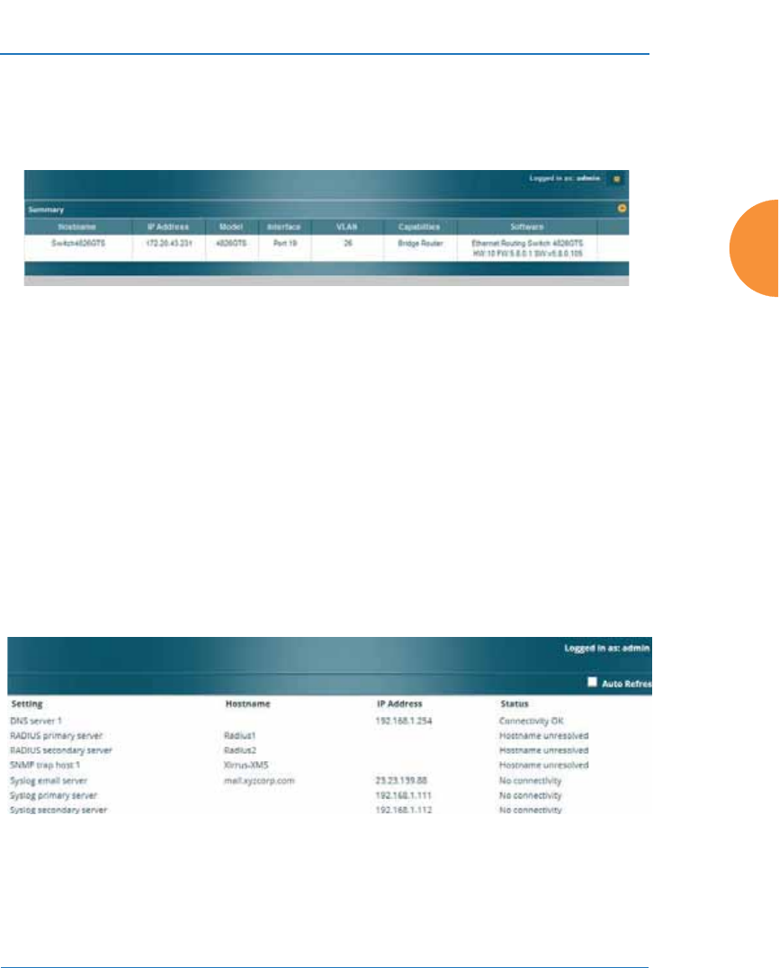
Wireless Access Point
Viewing Status on the Wireless AP 113
LLDP List
This status-only window lists devices on the AP’s network that support the Link
Layer Discovery Protocol (LLDP).
Figure 59. LLDP List
The AP performs discovery on the network on an ongoing basis. This list shows
the devices that have been discovered — devices on the network that have LLDP
running. For each, it shows the device’s host name, IP address, and model name,
the device interface that is connected to the network (i.e., the port that was
discovered), and the network capabilities of the device (switch, router, supported
protocols, etc.).
LLDP must be enabled on the AP in order to gather and display this information.
For details and some restrictions, see “LLDP Settings” on page 182.
Network Assurance
This status-only window shows the results of ongoing network assurance testing.
Figure 60. Network Assurance
The AP checks connectivity to network servers that you have configured (for
example, DNS and NTP servers) on an ongoing basis. For each server, this list
shows the server’s host name (if any), IP address, and status.

Wireless Access Point
114 Viewing Status on the Wireless AP
Network assurance must be enabled on the AP in order to perform these
connectivity tests and display this information. See “Management Control” on
page 238.
See Also
Management Control
Undefined VLANs
This status-only window lists VLANs that are detected on the AP’s trunk ports
(i.e., wired ports), but have not been configured on the AP. See “VLANs” on
page 213.
Figure 61. Undefined VLANs
This feature alerts you to the fact that an 802.1Q trunk to the AP has VLANs that
are not being properly handled on the AP. To reduce unnecessary traffic, only
VLANs that are actually needed on the AP should normally be on the trunk, e.g.,
the management VLAN and SSID VLANs. In some cases such as multicast
forwarding for Apple Bonjour you may want to extend other VLANs to the AP, in
order to forward Bonjour or other multicast packets (see “Advanced Traffic
Optimization” on page 324).
See Also
VLANs

Wireless Access Point
Viewing Status on the Wireless AP 115
RF Monitor Windows
Every Wireless AP includes an integrated RF spectrum analyzer as a standard
feature. The spectrum analyzer allows you to characterize the RF environment by
monitoring throughput, signal, noise, errors, and interference levels continually
per channel. This capability uses the assigned threat-sensor (monitor) radio. The
associated software is part of the ArrayOS.
The following RF Status windows are available:
z
IAP Monitoring — displays current statistics and RF measurements for
each of the AP’s IAPs.
z
Spectrum Analyzer — displays current statistics and RF measurements
for each of the AP’s channels.
z
Rogues — displays rogue APs that have been detected by the AP.
z
Channel History — charts ongoing statistics and RF measurements for
one selected channel over time.
z
Radio Assurance — displays counts of types of problems that caused each
IAP to reset.
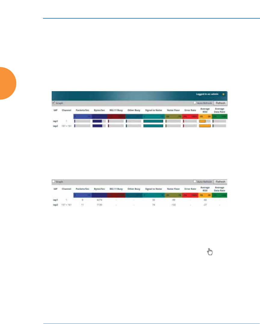
Wireless Access Point
116 Viewing Status on the Wireless AP
IAP Monitoring
The RF Monitor — IAP Monitoring window displays traffic statistics and RF
readings observed by each AP IAP (radio). Note that the data is an instantaneous
snapshot for the IAP — it is not an average or a cumulative total. To graph these
values over time for a particular channel, see “Channel History” on page 122. For
detailed information on the measurements displayed, please see “Spectrum
Analyzer Measurements” on page 119.
Figure 62. RF Monitor — IAPs
Figure 62 presents the data as a graphical display, enabled by selecting the Graph
checkbox on the upper left. If this option is not selected, data is presented as a
numerical table.
Figure 63. RF Monitor — IAPs
You may sort the rows based on any column that has an active column header,
indicated when the mouse pointer changes to the hand icon . Click Refresh to
update the information at any time. Click Auto Refresh to instruct the AP to
refresh this window automatically.

Wireless Access Point
Viewing Status on the Wireless AP 117
Spectrum Analyzer
Spectrum analysis on Wireless APs is a distributed capability that automatically
covers the entire wireless network, since a sensor is present in every unit. APs
monitor the network 24/7 and analyze interference anywhere in the network
from your desk. There’s no need to walk around with a device as with traditional
spectrum analyzers, thus you don’t have to be in the right place to find outside
sources that may cause network problems or pose a security threat. The AP
monitors all 802.11 radio bands (a/b/g/n), not just those currently used for data
transmission.
The RF Spectrum Analyzer window displays instantaneous traffic statistics and
RF readings for all channels, as measured by the AP’s monitor radio. This differs
from the RF Monitor-Radio Monitoring window, which displays values measured
by each IAP for its current assigned channel. For the spectrum analyzer, the
monitor radio is in a listen-only mode, scanning across all wireless channels. Each
channel is scanned in sequence, for a 250 millisecond interval per channel. The
spectrum analyzer window presents the data as a graphical display of vertical bar
graphs for each statistic as shown in Figure 64 (the default presentation), or
horizontally as bar graphs or numerical RF measurements. The measurements
displayed are explained in “Spectrum Analyzer Measurements” on page 119.
As an aid to viewing data for a particular channel, click the channel number. The
channel will be highlighted down the page (or across the page for a rotated view,
in both text and graph modes). Click additional channels to highlight them for
easy comparison. To remove the highlighting from a channel, click the channel
number again. Click Refresh to update the information at any time. Click Auto
Refresh to instruct the AP to refresh this window automatically.
#The RF measurements for this feature are obtained by the monitor radio. You
must have a radio set to monitor mode for any data to be available. See
“IAP Settings” on page 313.
#Spectrum Analysis is not available for APs or Access Points featuring
802.11ac IAPs.
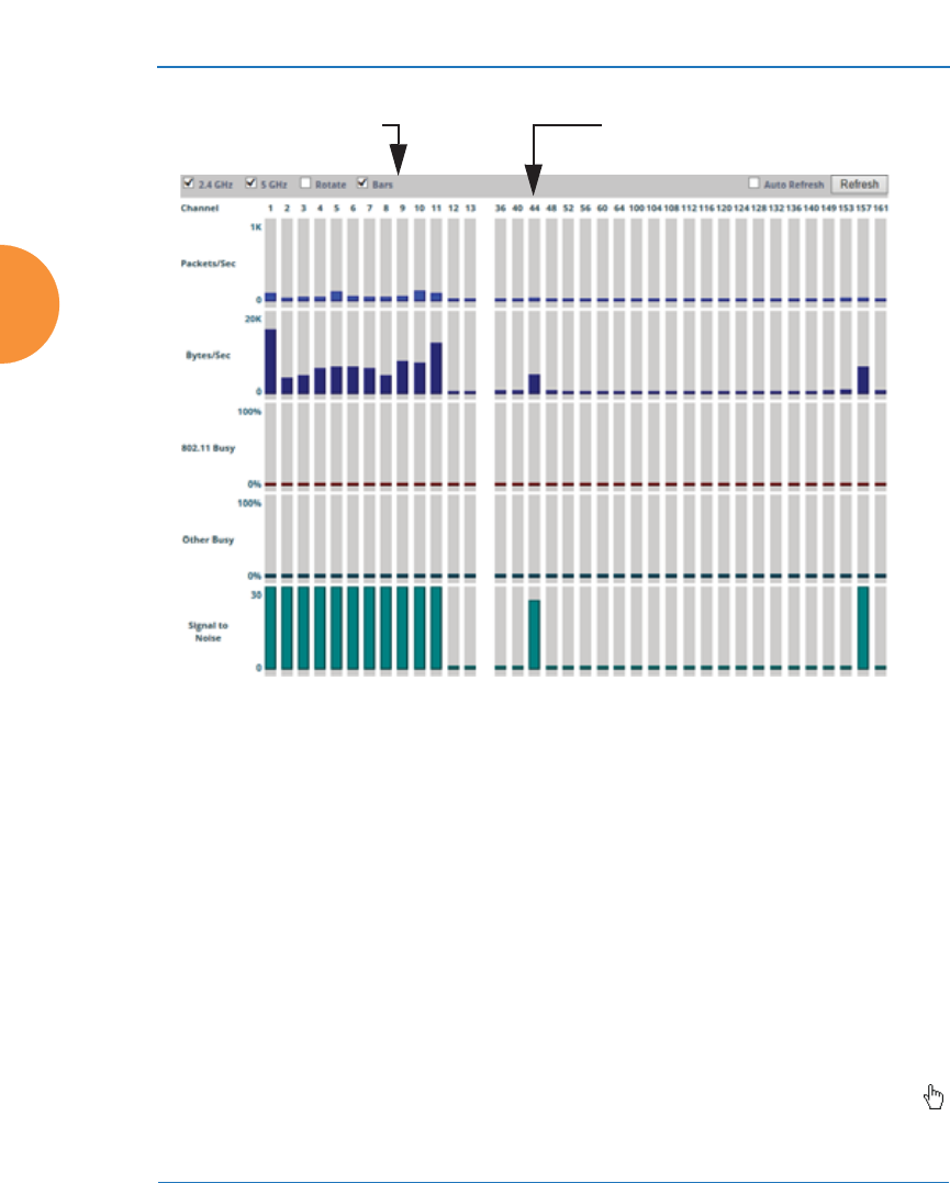
Wireless Access Point
118 Viewing Status on the Wireless AP
Figure 64. RF Spectrum Analyzer
The Spectrum Analyzer offers several display options:
z
To display horizontal bar graphs, click the Rotate checkbox at the bottom
of the data window.
z
In the rotated view, if you wish to view data as a numerical table, click the
Text checkbox. Click again to return to a graphical display. The text
option is only available in the rotated view.
z
When viewing a graphical display, click Bars to have the bar graphs
displayed against a gray background — you may find this easier on the
eyes. This operation is not available when Text is selected.
z
You may sort the rows based on any column that has an active column
header, indicated when the mouse pointer changes to the hand icon .
Sorting is only available in the rotated view.
Click Channel number to highlightSelect Display Options

Wireless Access Point
Viewing Status on the Wireless AP 119
z
At the bottom left of the frame, you may select whether to display only
2.4 GHz channels, 5 GHz channels, or both (the default is both). Note that
the data is an instantaneous snapshot — it is not an average or a
cumulative total.
Spectrum Analyzer Measurements
The spectrum analyzer displays the following information:
z
Packets/Sec: Total number of wireless packets per second on the channel,
both valid and errored packets.
z
Bytes/Sec: Total number of wireless bytes per second on the channel,
valid packets only.
z
802.11 Busy: Percentage of time that 802.11 activity is seen on the channel.
z
Other Busy: Percentage of time that the channel is unavailable due to
non-802.11 activity.
The total busy time (802.11 Busy plus Other Busy) will never total more
than 100%. The remaining time (100% minus total busy time) is quiet
time — the time that no activity was seen on the channel.
z
Signal to Noise: Average SNR (signal to noise ratio) seen on the channel,
calculated from the signal seen on valid 802.11 packets less the noise floor
level. A dash value “-“means no SNR data was available for the interval.
z
Noise Floor: Average noise floor reading seen on the channel (ambient
noise). A dash value “-“means no noise data was available for the
interval.
z
Error Rate: Percentage of the total number of wireless packets seen on the
channel that have CRC errors. The Error rate percentage may be high on
some channels since the monitor radio is set to receive at a very sensitive
level, enabling it to hear packets from devices at far distances.
z
Average RSSI: Average RSSI level seen on 802.11 packets received on the
channel. A dash value “-“means no RSSI data was available for the
interval.
z
Average Data Rate: Average data rate over time (per byte, not per packet)
seen on 802.11 packets received on the channel. A dash value “-“means
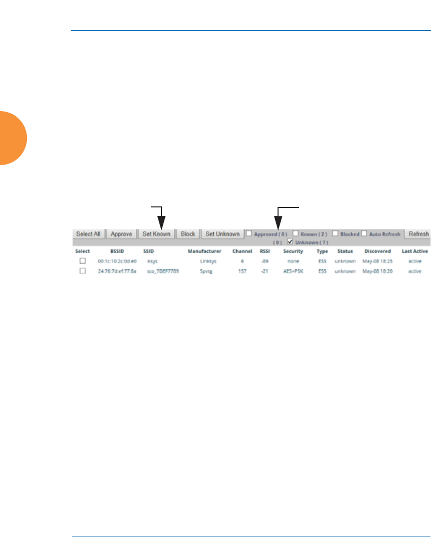
Wireless Access Point
120 Viewing Status on the Wireless AP
no data rate information was available for the interval. A higher date rate
(above 6 Mbps) typically indicates user data traffic on the channel.
Otherwise, the data rate reflects control packets at the lower basic rates.
Rogues
This window displays all detected access points, according to the classifications
you select from the checkboxes at the top — Blocked, Unknown, Known, or
Approved. This includes ad hoc access points (station-to-station connections). For
more information about intrusion detection, rogue APs, and blocking, please see
“About Blocking Rogue APs” on page 376.
Figure 65. Intrusion Detection/Rogue AP List
The Intrusion Detection window provides the easiest method for classifying
rogue APs as Blocked, Known, Approved, or Unknown. Choose one or more APs
using the checkbox in the Select column, then use the buttons on the upper left to
classify them with the following actions: Approve, Set Known, Block, or Set
Unknown.
You can sort the results based on the following parameters by clicking the desired
column header:
z
SSID
z
Security
z
BSSID
z
Type
z
Manufacturer
z
Status
z
Channel
z
Discovered
z
RSSI
z
Last Active
Select APs to DisplayClassify APs

Wireless Access Point
Viewing Status on the Wireless AP 121
You can refresh the list at any time by clicking on the Refresh button, or click in
the Auto Refresh check box to instruct the AP to refresh the list automatically.
See Also
Network Map
Rogue Control List
SSIDs
SSID Management
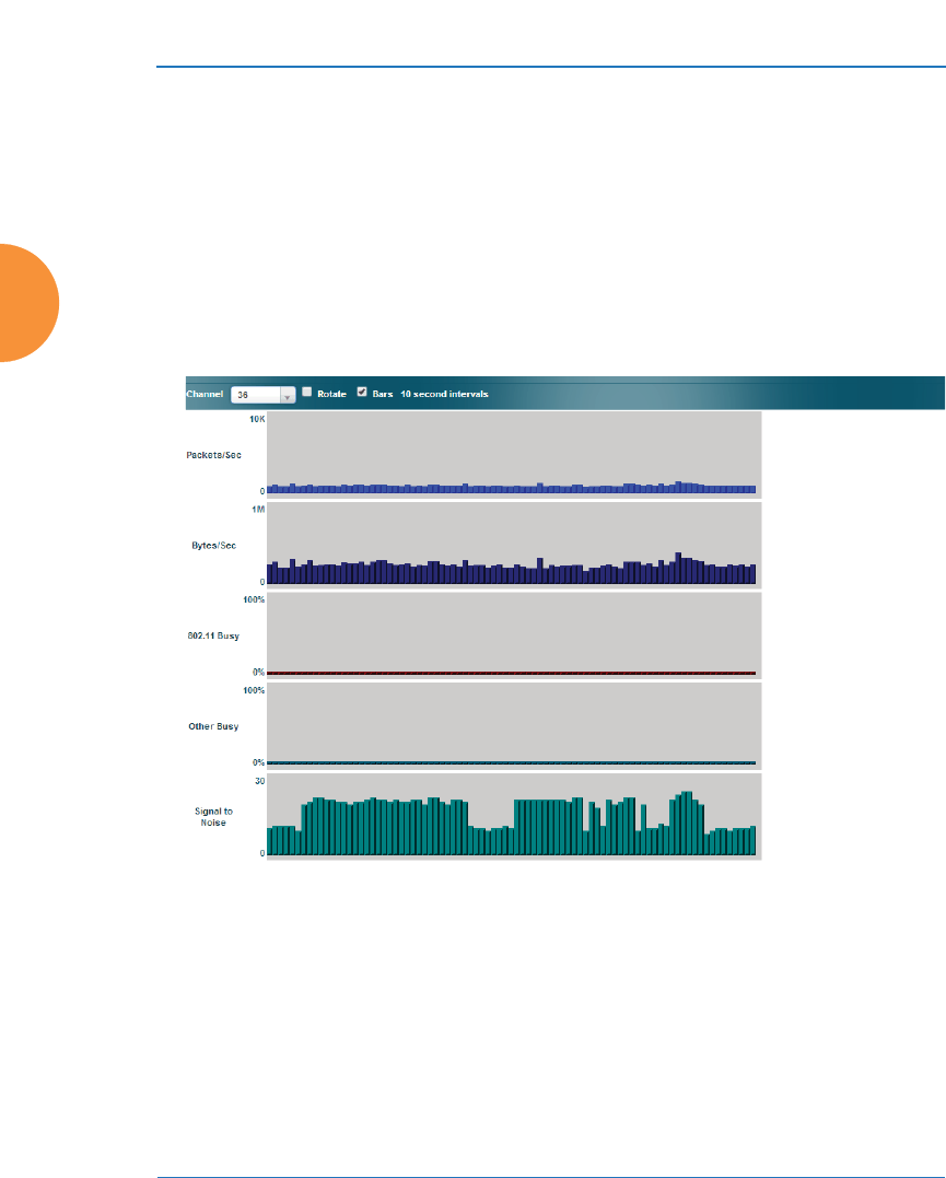
Wireless Access Point
122 Viewing Status on the Wireless AP
Channel History
The RF Monitor — Channel History window focuses on traffic statistics and RF
readings observed for just one channel that you select in the Channel field. A new
set of readings is added every 10 seconds for a 5 GHz channel, or every 5 seconds
for a 2.4 GHz channel. For descriptions of the measurements displayed, please see
“Spectrum Analyzer Measurements” on page 119.
Figure 66. RF Monitor — Channel History
Figure 66 presents the data in graphical form. New data appears at the left, with
older readings shifting to the right. To make the data appear as a bar chart, click
the Bar checkbox which will shade the background.
You also have the option of clicking the Rotate checkbox to give each statistic its
own column. In other words, the graph for each statistic will grow down the page
as new readings display at the top. (Figure 67)
#Channel History is not available for APs or Access Points featuring
802.11ac IAPs.
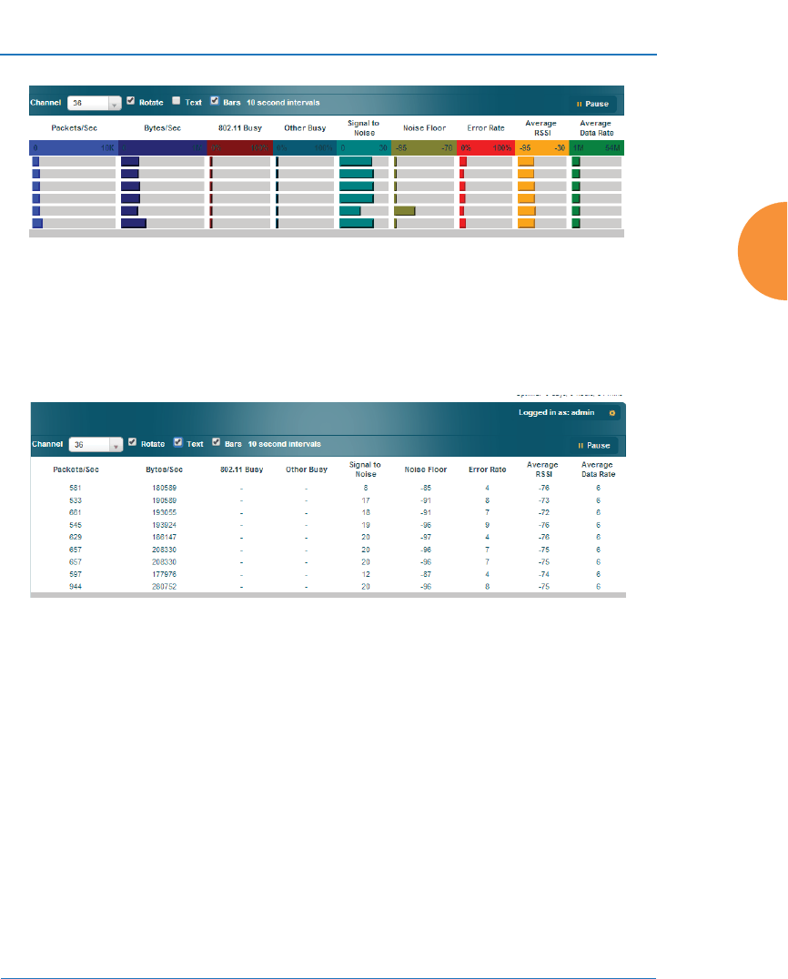
Wireless Access Point
Viewing Status on the Wireless AP 123
Figure 67. RF Monitor — Channel History (Rotated)
If you select Rotate and Text together, data is presented as a numerical table.
(Figure 68)
Click Pause to stop collecting data, or Resume to continue.
Figure 68. RF Monitor — Channel History (Text)

Wireless Access Point
124 Viewing Status on the Wireless AP
Radio Assurance
When Radio Assurance mode is enabled, the monitor radio performs loopback
tests on the AP’s radios. When problems are encountered, the AP can take various
actions to correct them by performing different levels of reset on the affected
radio. This window shows which resets, if any, have been performed on which
radios since the last reboot.
The AP’s response to radio problems is controlled by the Radio Assurance Mode
selected, as described in “RF Resilience” on page 360. If you have selected Failure
Alerts & Repairs (with or without reboots), then the AP can take corrective action
if a problem is detected. Note that radio assurance requires RF Monitor Mode to
be enabled in Advanced RF Settings to turn on self-monitoring functions. It also
requires a radio to be set to monitoring mode. For a detailed discussion of the
operation of this feature and the types of resets performed, see “Radio Assurance”
on page 530.
Figure 69. Radio Assurance
For each of the AP’s radios, this window shows the radio’s state, its type (IEEE
802.11 type, and antenna type—2x2 or 3x3), the assigned channel, and the selected
802.11 wireless mode. To the right, the table shows counts for the number of
times, if any, that radio assurance has performed each of the following types of
resets since the last reboot, as described in Radio Assurance:
z
Monitor
z
Beacon
z
Phy
z
MAC
z
System (i.e., reboot the AP)

Wireless Access Point
Viewing Status on the Wireless AP 125
See Also
IAPs
Xirrus Advanced RF Analysis Manager (RAM)
RF Resilience
Radio Assurance

Wireless Access Point
126 Viewing Status on the Wireless AP
Station Status Windows
The following Station Status windows are available:
z
Stations — this list describes all stations associated to the AP.
z
Location Map — displays a map showing the approximate locations of all
stations associated to the AP.
z
RSSI — for each associated station, this displays the Received Signal
Strength Indicator at each of the AP’s IAPs.
z
Signal-to-Noise Ratio (SNR) — for each associated station, this displays
the SNR at each of the AP’s IAPs.
z
Noise Floor — for each associated station, this displays the ambient noise
(silence) value at each of the AP’s IAPs.
z
Max by IAP — for each IAP, this shows the historical maximum number
of stations that have been associated to it over various periods of time.
z
Station Assurance — displays stations that are having connectivity
problems.

Wireless Access Point
Viewing Status on the Wireless AP 127
Stations
This window shows client stations currently visible to the AP. You may choose to
view only stations that have Associated to the AP, or include stations that are
Unassociated by selecting the appropriate buttons above the list. The list always
shows the MAC address of each station, its IP address, the SSID used for the
association, the Group (if any) that this station belongs to, its VLAN, its QoS, the
IAP used for the association, transmit and receive rates, the RSSI for each station,
and how long each association has been active (up time).
In the Link column, click the details button to jump to a detailed statistics
page for this station. Click to see Application Control information.
You may click other buttons above the list to show a number of additional
columns:
z
Identification: shows more identifying information for the station — its
User Name, Host Name, Manufacturer, Device Type, and Device Class
(for example, notebook, iPad, etc.).
z
Security: includes security settings used by the connection — Encryption
type, Cipher used, and Key Management used by the station.
z
Connection Info: shows the Band (5GHz or 2.4 GHz) used. Shows an
additional RF measurement that affects the quality of the connection:
SNR (signal to noise ratio).
z
Reset: click this button to return the display to showing just the default
columns.
Figure 70. Stations

Wireless Access Point
128 Viewing Status on the Wireless AP
You may sort the rows based on any column that has an active column header.
Click again to reverse the sort order. You may select one or more specific stations
and perform one of the following actions by clicking the associated button:
z
Deny Access: Sends a de-authentication frame to the selected station and
explicitly denies it access by adding its MAC address to the Deny List in
the Access Control List window. To permit access again, go to “Access
Control List” on page 248 and delete the station from the Deny list.
z
Deauthenticate: Sends a de-authentication frame to the selected station.
The station may re-authenticate.
Click on the Refresh button to refresh the station list, or click in the Auto Refresh
check box to instruct the AP to refresh this window automatically.
See Also
Access Control List
Station Status Windows
Station Statistics
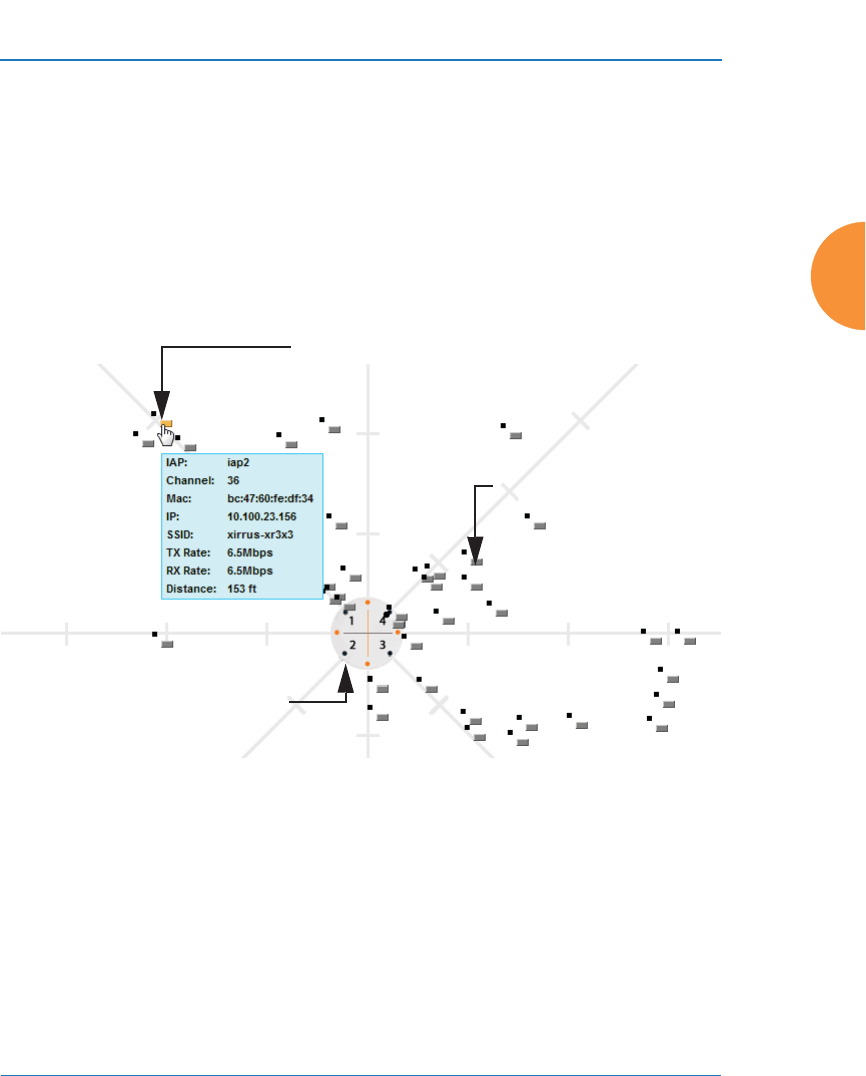
Wireless Access Point
Viewing Status on the Wireless AP 129
Location Map
The Location Map shows the approximate locations of stations relative to this AP.
The location of each station is computed based on the RSSI of its signal as received
by the AP. The distance is adjusted based on the environment setting that you
selected. You may display just the stations associated to this AP, unassociated
stations (shown in gray), or both. The station count is shown on the right, above
the map. You may also choose to display only 5 GHz stations (shown in orange)
or 2.4 GHz stations (shown in green), or both.
Figure 71. Location Map
The map and AP are shown as if you were looking down on the AP from above,
say from a skylight on the roof. Thus the positions of the radios are a mirror image
of the way they are typically drawn when looking at the face of the AP. Radios are
marked on the map to show the orientation of the AP.
A station is identified by the type of Preferred Label that you select: Netbios
Name, IP Address, MAC Address, or Manufacturer. If multiple stations are near
each other, they will be displayed slightly offset so that one station does not
Associated Stations
orange - 5 GHz
green - 2.4GHz
Unassociated Station
Hover mouse to
show details
AP

Wireless Access Point
130 Viewing Status on the Wireless AP
completely obscure another. You may minimize a station that is not of interest by
clicking it. There is also a Minimize All button.
You may replace the range-finder background image above with your own
custom image of the floor plan of the area served by the AP — see “Working with
the Custom Image” on page 132
Hover the mouse over a station to show detailed information. (Figure 71) For a
station that is associated to this AP, the details include:
z
The IAP, Channel, and SSID to which the station is associated.
z
The MAC and IP address and Netbios name of the station.
z
The TX Rate and RX Rate of this connection.
z
The approximate Distance of this station from the AP. The distance is
estimated using the received signal strength and your environment
setting. The environment determines the typical signal attenuation due to
walls and other construction that affect signal reception.
Controls and items displayed on the Location Map window
Figure 72. Controls for Location Map
#The Location Map has its own scroll bars in addition to the browser’s scroll
bars. If you narrow the browser window, the map’s scroll bar may be hidden.
Use the browser’s bottom scroll bar if you need to move it into view.
Stations
to display Environment
Setting
Replace background
Minimize stations
Reset display Rotate map
Zoom in
Zoom out
Scale
Station counts

Wireless Access Point
Viewing Status on the Wireless AP 131
z
Display Associated/Unassociated: Select whether to display stations that
are associated to the AP, stations that are not associated, or both.
z
Display 2.4 GHz/5 GHz: Select whether to display 802.11bgn stations, or
802.11an stations, or both.
z
Preferred Label: This field is located on the top of the window towards
the right. It shows the type of label to be displayed for stations: NetBIOS
is the default, else, an IP or MAC address will be used, in that order.
z
Auto Refresh: Instructs the AP to refresh this window automatically.
z
Refresh: Updates the stations displayed.
z
Custom Image: Use this feature to replace the default background image
with your own image of the floor plan of your location. Click the Browse
button and browse to the desired file on your computer. This may be
a .gif, .jpg, .jpeg., .png, .htm, or .html file. The scale of the file should be
100 feet per inch. Then click Upload (see below). For more information on
using the custom, image, see “Working with the Custom Image” on
page 132.
z
Upload: After browsing to the desired custom image, click the Upload
button to install it. The map is redisplayed with your new background.
No hash marks (for the map scale) are added to the image display.
z
Reset: Click this button to restore the map display to the factory settings.
All attributes are restored — including the stations selected for display, the
scale, the rotation, and the background map.
z
Rotate: Click this button to rotate the orientation of the entire map. It
rotates the map 45o counter-clockwise.
z
Enlarge: Click this button to enlarge (zoom in on) the map. The displayed
Scale is updated with the new scale for the map.
z
Reduce: Click this button to reduce (zoom out on) the map.
The displayed Scale is updated with the new scale for the map.
z
Environment: This field is located on the top right of the window. Select
the type of environment for this AP’s deployment: Indoor open (few
walls or obstructions), Indoor walled (typical wall or cubicle

Wireless Access Point
132 Viewing Status on the Wireless AP
construction), or Indoor dense (many walls or obstructions, or unusually
dense walls).
z
Scale: This view-only value shows the approximate distance represented
by each hash mark on the default map background.
z
Associated, Unassociated, Total Stations: These view-only values show
the station counts observed by the AP.
See Also
Station Status Windows
Working with the Custom Image
After you have uploaded a custom image (see Custom Image and Upload in
“Controls and items displayed on the Location Map window” on page 130), you
should move the display of the AP on your map to correspond with its actual
location at your site.
To move the AP on the map, simply click it, then drag and drop it to the desired
location. The AP will continue to follow the mouse pointer to allow you to make
further changes to its location. When you are satisfied with its location, click the
AP again to return to normal operation.
RSSI
For each station that is associated to the AP, the RSSI (Received Signal Strength
Indicator) window shows the station’s RSSI value as measured by each IAP. In
other words, the window shows the strength of the station’s signal at each radio.
You may choose to display Unassociated Stations as well with a checkbox at the
bottom of the window.
Figure 73. Station RSSI Values
By default, the RSSI is displayed numerically. You may display the relative
strength using color if you select Colorize Intensity, with the strongest signals
indicated by the most intense color. (Figure 73) If you select Graph, then the RSSI

Wireless Access Point
Viewing Status on the Wireless AP 133
is shown on a representation of the AP, either colorized or numerically based on
your selection. (Figure 74) The stations are listed to the left of the AP — click on a
station to show its RSSI values on the AP.
Figure 74. Station RSSI Values — Colorized Graphical View
In either graphical or tabular view, you may sort the rows based on any column
that has an active column header, indicated when the mouse pointer changes to
the hand icon . Click on the Refresh button to refresh the station list, or click in
the Auto Refresh check box to instruct the AP to refresh this window
automatically.
See Also
Station Status Windows
RF Monitor Windows
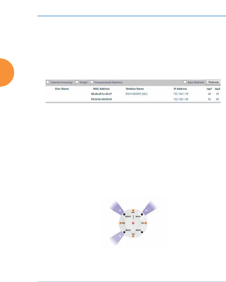
Wireless Access Point
134 Viewing Status on the Wireless AP
Signal-to-Noise Ratio (SNR)
For each station that is associated to the AP, the Signal-to-Noise Ratio (SNR)
window shows the station’s SNR value as measured by each IAP. In other words,
the window shows the SNR of the station’s signal at each IAP. The signal-to-noise
ratio can be very useful for determining the cause of poor performance at a
station. A low value means that action may need to be taken to reduce sources of
noise in the environment and/or improve the signal from the station.
Figure 75. Station Signal-to-Noise Ratio Values
You may choose to display Unassociated Stations as well with a checkbox at the
bottom of the window.
By default, the SNR is displayed numerically. (Figure 75) You may display
the relative value using color if you select Colorize Intensity, with the highest
SNR indicated by the most intense color. (Figure 76) If you select Graph, then
the SNR is shown on a representation of the AP, either colorized or numerically
based on your selection. The stations are listed to the left of the AP — click on a
station to show its SNR values on the AP.
Figure 76. Station SNR Values — Colorized Graphical View
In either graphical or tabular view, you may sort the rows based on any column
that has an active column header, indicated when the mouse pointer changes to
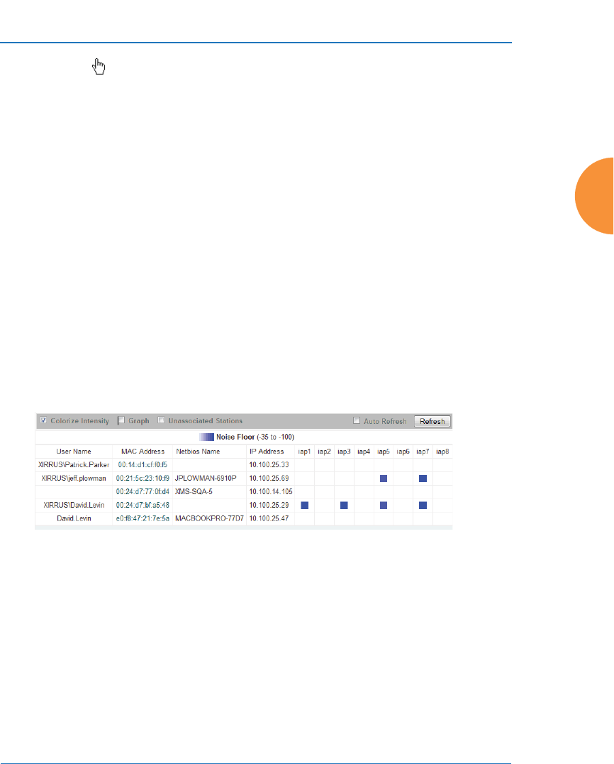
Wireless Access Point
Viewing Status on the Wireless AP 135
the hand icon . Click on the Refresh button to refresh the station list, or click in
the Auto Refresh check box to instruct the AP to refresh this window
automatically.
See Also
Station Status Windows
RF Monitor Windows
Noise Floor
For each station that is associated to the AP, the Noise Floor window shows
the ambient noise affecting a station’s signal as measured by each IAP. The noise
floor is the RSSI value when the station is not transmitting, sometimes called a
Silence value. In other words, the window shows the noise floor of the station’s
signal at each IAP. The noise floor value can be very useful for characterizing the
environment of a station to determine the cause of poor performance. A relatively
high value means that action may need to be taken to reduce sources of noise in
the environment.
Figure 77. Station Noise Floor Values
You may choose to display Unassociated Stations as well with a checkbox at the
bottom of the window.
By default, the noise floor is displayed numerically. (Figure 77) You may display
the relative value using color if you select Colorize Intensity, with the highest
noise indicated by the most intense color. If you select Graph, then the ambient
noise is shown on a representation of the AP, either colorized or numerically
based on your selection.(Figure 78) The stations are listed to the left of the AP —
click on a station to show its values on the AP.

Wireless Access Point
136 Viewing Status on the Wireless AP
Figure 78. Station Noise Floor Values — Colorized Graphical View
In either graphical or tabular view, you may sort the rows based on any column
that has an active column header, indicated when the mouse pointer changes to
the hand icon . Click on the Refresh button to refresh the station list, or click in
the Auto Refresh check box to instruct the AP to refresh this window
automatically.
See Also
Station Status Windows
RF Monitor Windows
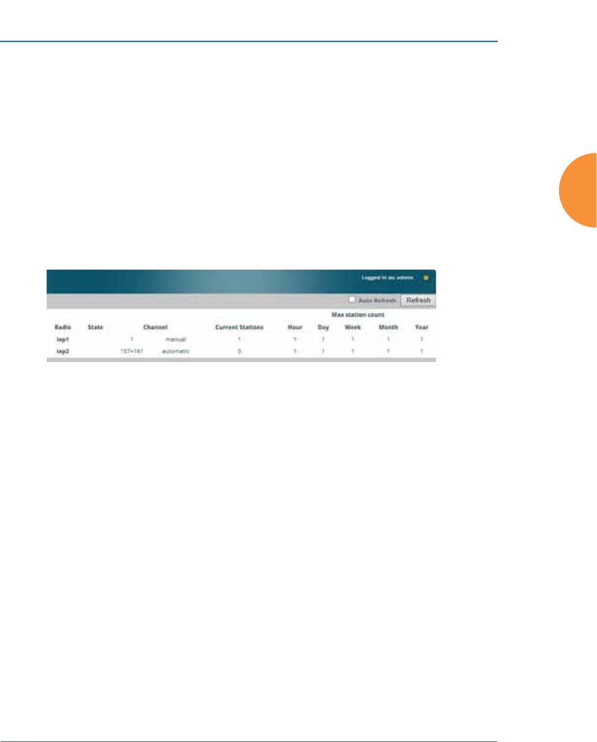
Wireless Access Point
Viewing Status on the Wireless AP 137
Max by IAP
This status-only window shows the maximum number of client stations that have
historically been associated to the AP. For each IAP, the list shows the IAP’s state
and channel number, the current number of stations associated, and the highest
number of stations that have been associated over various periods of time: hour,
day, week, month, and year. In other words, the Max Station Count shows the
“high water mark” over the selected period of time — the maximum count of
stations for the selected period, rather than a cumulative count of all stations that
have associated. This information aids in network administration and in planning
for additional capacity.
Figure 79. Max by IAP
You may click an IAP to go to the IAP Settings window. Click on the Refresh
button to refresh the station list, or click Auto Refresh to instruct the AP to refresh
this window automatically.
See Also
IAPs
Station Status Windows
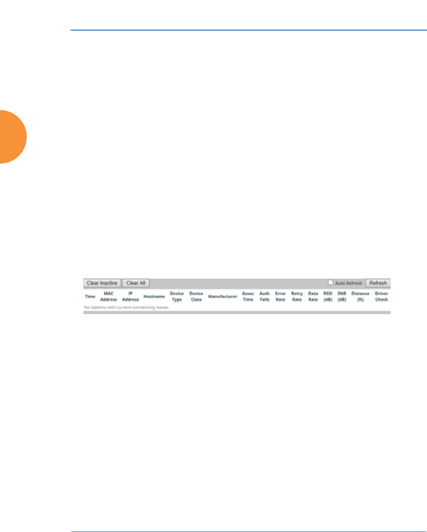
Wireless Access Point
138 Viewing Status on the Wireless AP
Station Assurance
Station assurance monitors the quality of the connections that users are
experiencing on the wireless network. This window shows client stations that
have had connectivity issues. You may enable or disable the station assurance
feature and set thresholds for the problems that it checks, such as excessive packet
retry or packet error rates, or stations that are unable to stay associated to the AP.
Please see “Station Assurance” on page 365 for more information about these
settings. When the AP detects that a station has reached the threshold value for
one or more of the issues checked, it adds the station to this page. In addition, an
event is triggered, a trap is generated, and a Syslog message is logged.
For each station, this list shows the MAC address, its IP address, its host name, its
device type, device class, and manufacturer. It also shows the values of the
various statistics that were monitored for problems as described in “Station
Assurance” on page 365: associated time, authentication failures, packet error
rate, packet retry rate, packet data rate, RSSI, signal to noise ratio (SNR), and
distance.
Figure 80. Station Assurance
You may click the Clear Inactive button to remove stations that are no longer
connected to the AP from the list. Click the Clear All button to remove all entries
and start fresh to add problem stations to the list as they are detected. Click on the
Refresh button to refresh the station list, or click Auto Refresh to instruct the AP
to refresh this window automatically.
See Also
IAPs
Station Status Windows
Station Assurance

Wireless Access Point
Viewing Status on the Wireless AP 139
Statistics Windows
The following AP Statistics windows are available:
z
IAP Statistics Summary — provides an overview of the statistical data
associated with all IAPs. Expands to show links for displaying detailed
statistics for individual IAPs.
z
Per-IAP Statistics — provides detailed statistics for an individual IAP.
z
Network Statistics — displays statistical data associated with each
network (Ethernet) interface.
z
VLAN Statistics — provides statistical data associated with your assigned
VLANs.
z
WDS Statistics — provides statistical data for all WDS client and host
links.
z
IDS Statistics — provides statistical data for intrusion detection.
z
Filter Statistics — provides statistical data for all configured filters.
z
Station Statistics — provides statistical data associated with each station.
IAP Statistics Summary
This is a status only window that provides an overview of the statistical data
associated with all IAPs. It also shows the channel used by each IAP. For detailed
statistics for a specific IAP, see “Per-IAP Statistics” on page 140. Click the Unicast
Stats Only checkbox on the lower left to filter the results, or clear the checkbox to
show statistics for all wireless traffic.
Figure 81. IAP Statistics Summary Page
You can Refresh the data (update the window with the latest information) or
Clear the data (reset all content to zero and begin counting again) at any time by

Wireless Access Point
140 Viewing Status on the Wireless AP
clicking on the appropriate button. You can also click in the Auto Refresh check
box to instruct the AP to refresh this window automatically.
See Also
System Log Window
Global Settings
Global Settings .11an
Global Settings .11bgn
IAPs
Per-IAP Statistics
This is a status only window that provides detailed statistics for the selected IAP.
Scroll the window down to see a breakout of the statistics by connection rate. For
a summary of statistics for all IAPs, see “IAP Statistics Summary” on page 139.
Use the Display Percentages checkbox at the upper left to select the output
format — check this option to express each statistic as a percentage of the total at
the top of the column, or leave it blank to display raw numbers.
Receive Error statistics include:
z
Total Retries: the count of packets that were sent more than once before
being received correctly.
z
CRC error: the count of packets that were corrupted on the air and were
dropped. Some level of CRC errors are expected in wireless networks.
Note that all IAPs operate in a mode where they are listening to
everything all the time, which means they will see many CRC errors.
z
Fragment Errors: the count of packets that were incomplete.
z
Encryption Errors: the count of packets that had encryption problems.
z
Duplicates: the count of packets that were received more than once. The
duplicate packets are dropped.
z
Dropped Packets: the count of packets that were dropped due to various
receive errors, including being received when all receive queues were
full. These packets are dropped after being received.
z
Overruns: indicate the number of times that First-In-First-Out (FIFO)
overflow errors occur.
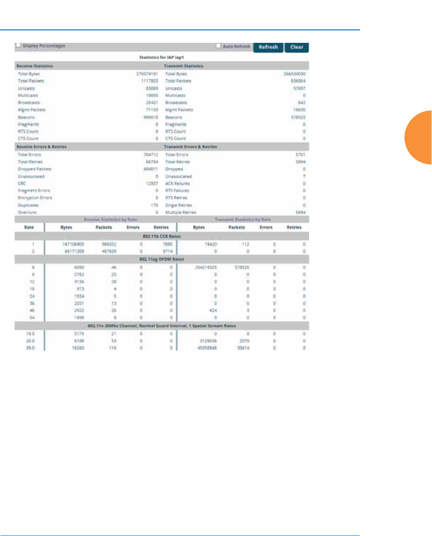
Wireless Access Point
Viewing Status on the Wireless AP 141
Figure 82. Individual IAP Statistics Page
You can Refresh the data (update the window with the latest information) or
Clear the data (reset all content to zero and begin counting again) at any time by
clicking on the appropriate button. You can also click in the Auto Refresh check
box to instruct the AP to refresh this window automatically.
See Also
System Log Window
Global Settings
Global Settings .11an
Global Settings .11bgn
IAPs
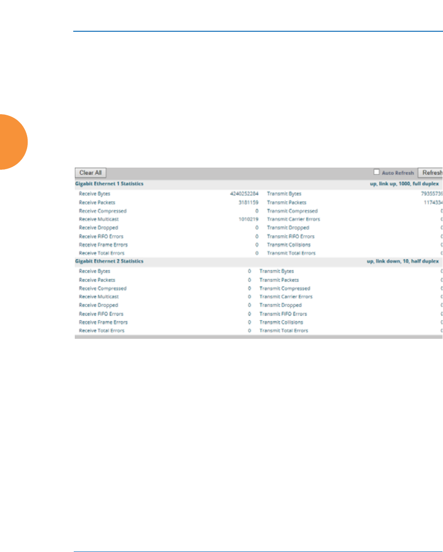
Wireless Access Point
142 Viewing Status on the Wireless AP
Network Statistics
This is a status only window that allows you to review statistical data associated
with each network (Ethernet) interface and its activity. You can Refresh the data
(update the window with the latest information) or Clear the data (reset all
content to zero and begin counting again) at any time by clicking on the
appropriate button. You can also click in the Auto Refresh check box to instruct
the AP to refresh this window automatically. If you are experiencing problems on
the AP, you may also want to print this window for your records
.
Figure 83. Network Statistics
See Also
DHCP Server
DNS Settings
Network
Interfaces
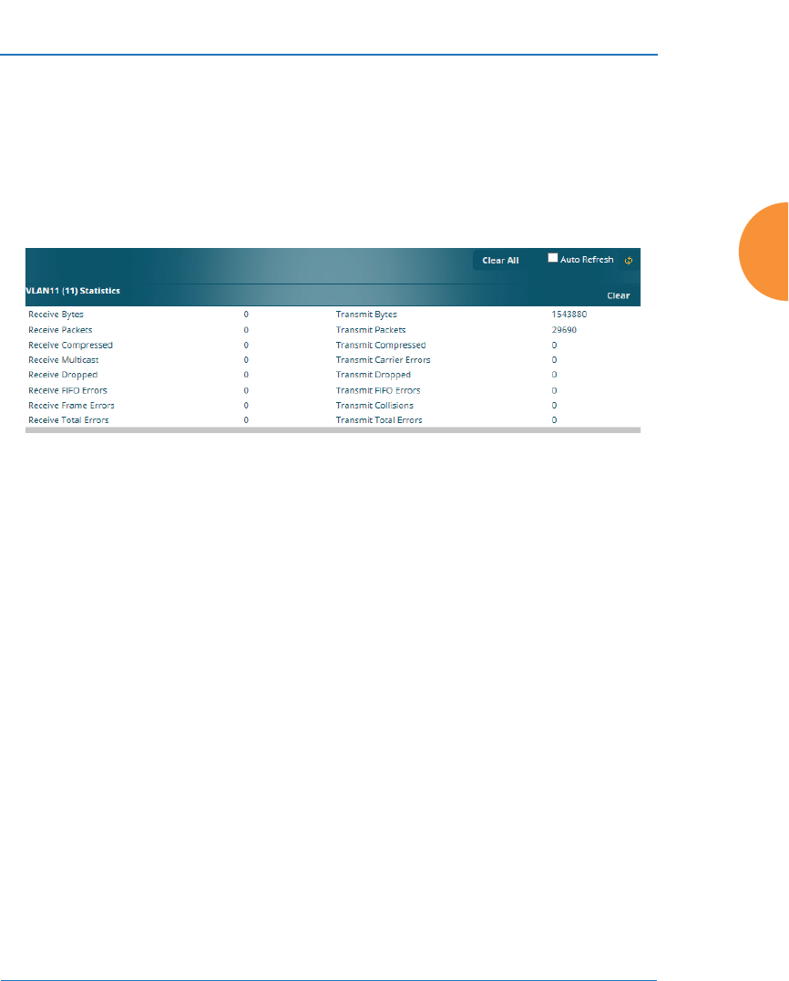
Wireless Access Point
Viewing Status on the Wireless AP 143
VLAN Statistics
This is a status only window that allows you to review statistical data associated
with your assigned VLANs. You can refresh the information that is displayed on
this page at any time by clicking on the Refresh button, or select the Auto Refresh
option for this window to refresh automatically. The Clear All button at the lower
left allows you to clear (zero out) all VLAN statistics.
Figure 84. VLAN Statistics
See Also
VLAN Management
VLANs
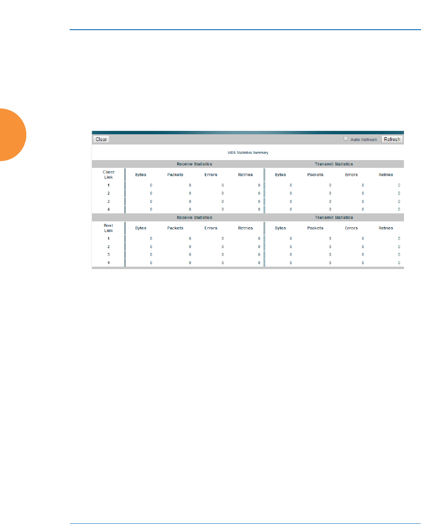
Wireless Access Point
144 Viewing Status on the Wireless AP
WDS Statistics
The main WDS Statistics window provides statistical data for all WDS client and
host links. To access data about a specific WDS client or host link, simply click on
the desired link in the left frame to access the appropriate window. You may also
choose to view a sum of the statistics for all client links, all host links, or all links
(both client and host links).
Figure 85. WDS Statistics
See Also
SSID Management
WDS
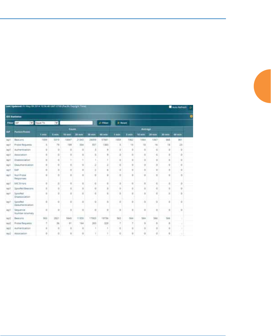
Wireless Access Point
Viewing Status on the Wireless AP 145
IDS Statistics
The Xirrus AP employs a number of IDS/IPS (Intrusion Detection System/
Intrusion Prevention System) strategies to detect and prevent malicious attacks on
the wireless network. This status-only window provides detailed intrusion
detection statistics for the selected IAP.
You must have Intrusion Detection Mode enabled to collect IDS statistics. See
“Intrusion Detection” on page 373. Information about IDS events is discussed in
the “IDS Event Log Window” on page 158.
Figure 86. IDS Statistics Page
Use the filter feature to show only information for a selected IAP or for selected
event types. Select the type of Filter: IAP to select IAPs, or Packet/Event to select
particular attack types. Select the type of string matching, for example, Begins
with or Contains. Then enter the string to be matched and click the Filter button.
For example, in Figure 87, the filter Packet/Event Contains assoc finds events that
include the string assoc in any position. If you have an AP with 12 IAPs, then IAP
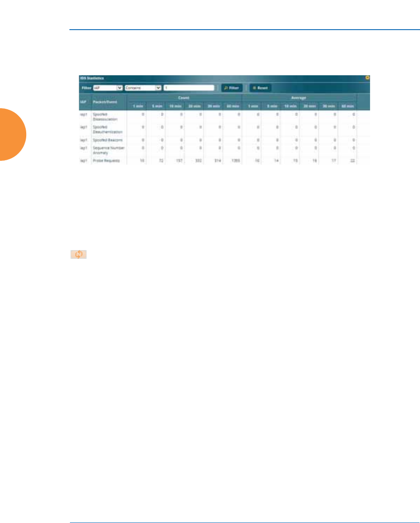
Wireless Access Point
146 Viewing Status on the Wireless AP
Contains 1 will show entries for iap1, iap10, iap11, and iap12. Click the Reset
button to return to showing all entries.
Figure 87. Filtered IDS Statistics
Many of the column headers may be clicked to sort the entries in ascending or
descending order based on that column. You can Refresh the data (update the
window with the latest information) at any time by clicking the Refresh button
on the upper right. You can also click in the Auto Refresh check box to
instruct the AP to refresh this window automatically.
See Also
Intrusion Detection
IDS Event Log Window
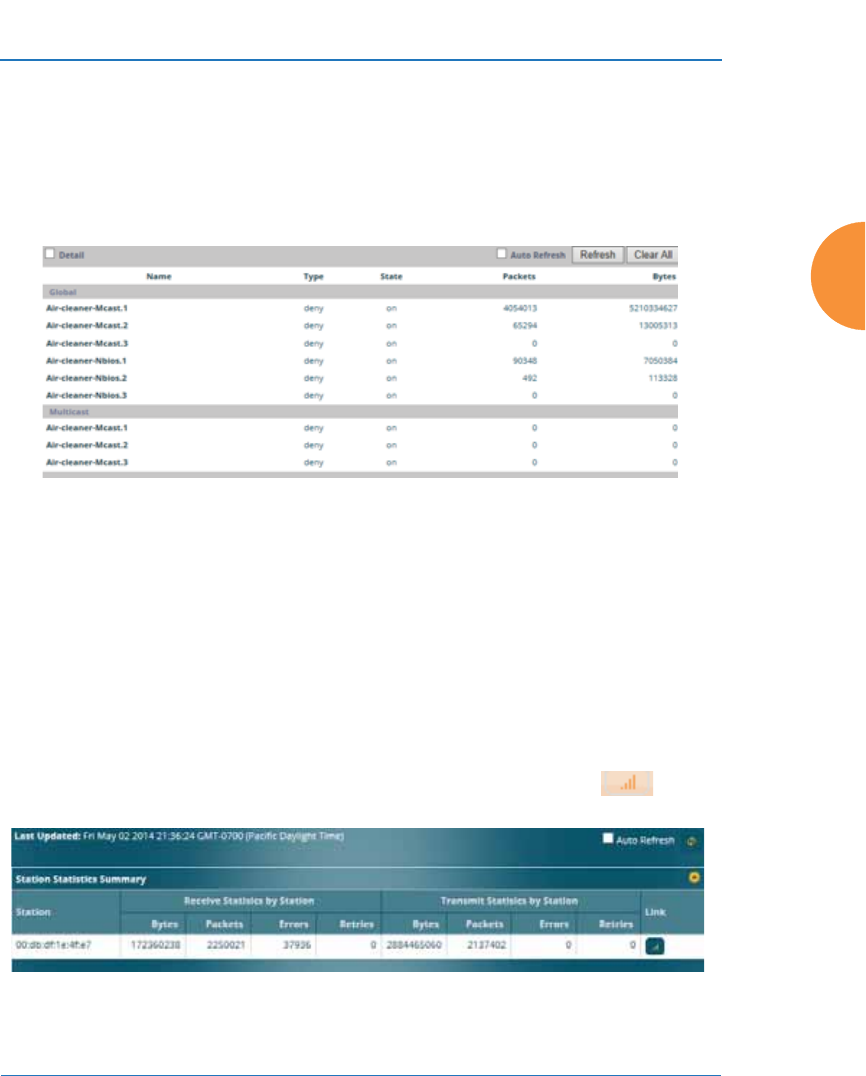
Wireless Access Point
Viewing Status on the Wireless AP 147
Filter Statistics
The Filter Statistics window provides statistical data for all configured filters. The
name, state (enabled — on or off), and type (allow or deny) of each filter is shown.
For enabled filters, this window shows the number of packets and bytes that met
the filter criteria. Click on a column header to sort the rows based on that column.
Click on a filter name to edit the filter settings.
Figure 88. Filter Statistics
See Also
Filters
Application Control Windows
Station Statistics
This status-only window provides an overview of statistical data for all stations.
Stations are listed by MAC address, and Receive and Transmit statistics are
summarized for each. For detailed statistics for a specific station, click the desired
MAC address in the Station column or click the details button in the
station’s Link column, and see “Per-Station Statistics” on page 149.
Figure 89. Station Statistics

Wireless Access Point
148 Viewing Status on the Wireless AP
Click on a column header to sort the rows based on that column. You can Refresh
the data (update the window with the latest information) at any time by clicking
the refresh button . You can also click in the Auto Refresh check box to
instruct the AP to refresh this window automatically.
See Also
Per-Station Statistics
Stations
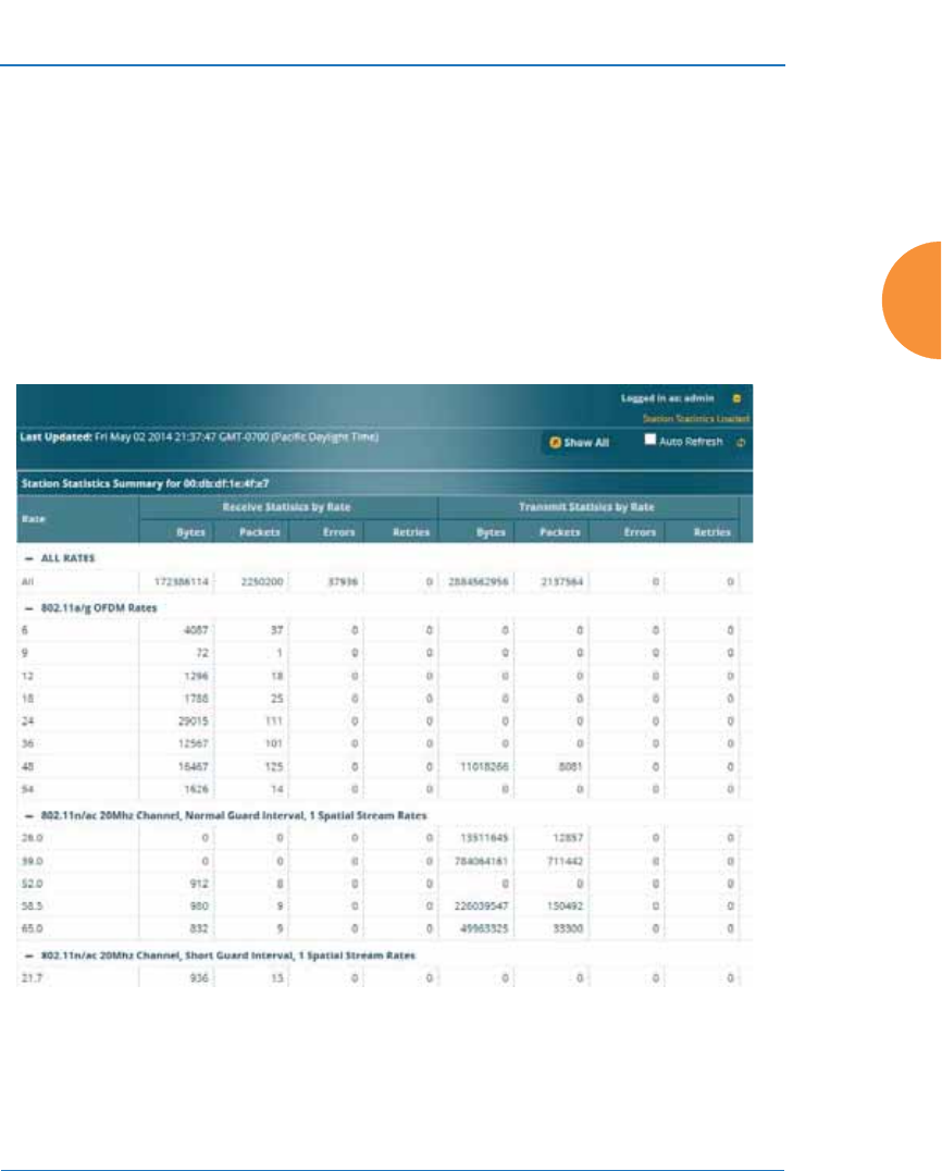
Wireless Access Point
Viewing Status on the Wireless AP 149
Per-Station Statistics
This window provides detailed statistics for the selected station. This window is
accessed from the Station Statistics window — click the MAC address of the
desired entry in the Station column to display its Per-Station Statistics window.
Receive and Transmit statistics are listed by Rate — this is the data rate in Mbps.
For a summary of statistics for all stations, see “Station Statistics” on page 147.
You can Refresh the data (update the window with the latest information) at any
time by clicking on the appropriate button. You can also click in the Auto Refresh
check box to instruct the AP to refresh this window automatically.
Figure 90. Individual Station Statistics Page
See Also
Station Statistics

Wireless Access Point
150 Viewing Status on the Wireless AP
Application Control Windows
The Application Control feature provides real-time visibility of application usage
by users across the wireless network. Network usage has changed enormously in
the last few years, with the increase in smart phone and tablet usage stressing
networks. Increasing traffic from legitimate business needs such as cloud- and
web-based applications, streaming media and VoIP must be handled with an
adequate quality of experience.
Application Control is discussed in the following topics:
z
About Application Control — an overview of this feature.
z
Application Control — displays information about applications running
on the wireless network.
z
Stations (Application Control) — displays a list of stations. Click one to
analyze application control information for only that station.
About Application Control
The AP uses Deep Packet Inspection (DPI) to determine what applications are
being used and by whom, and how much bandwidth they are consuming. These
applications are rated by their degree of risk and productiveness. Filters can be
used to implement per-application policies that keep network usage focused on
productive uses:
z
Usage of non-productive and risky applications like BitTorrent can be
restricted using Filters.
z
Traffic for mission-critical applications like VoIP and WebEx may be given
higher priority (QoS).
z
Non- critical traffic from applications like YouTube may be given lower
priority (QoS).
z
Traffic flows for specific applications may be controlled by sending them
into VLANs that are designated for that type of traffic.
#This feature is only available if the AP license includes Application
Control. See “About Licensing and Upgrades” on page 412.

Wireless Access Point
Viewing Status on the Wireless AP 151
Application Control can track application usage over time to monitor trends.
Usage may be tracked by AP, VLAN, or station. Many hundreds of applications
are recognized and grouped into a number of categories. The distributed
architecture of Xirrus APs allows Application Control to scale naturally as you
grow the network.
About Risk and Productivity
Application Control ranks applications in terms of their levels of risk and
productivity.
Productivity indicates how appropriate an application is for business purposes.
The higher the rating number, the more business-oriented an application is.
z
1—Primarily recreational
z
2—Mostly recreational
z
3—Combination of business and recreational purposes
z
4—Mainly used for business
z
5—Primarily used for business
Risk indicates how likely an application is to pose a threat to the security of your
network. The higher the rating number, the more risky an application is.
z
1—No threat
z
2—Minimal threat
z
3—Some risk - may be misused
z
4—High risk - may be malware or allow data leaks
z
5—Very high risk - threat circumvents firewalls or avoids detection
Keeping Application Control Current
Applications are recognized using a signature file which may be updated using
the System Tools page as new applications become popular (see “Application
Control Signature File Management” on page 422).
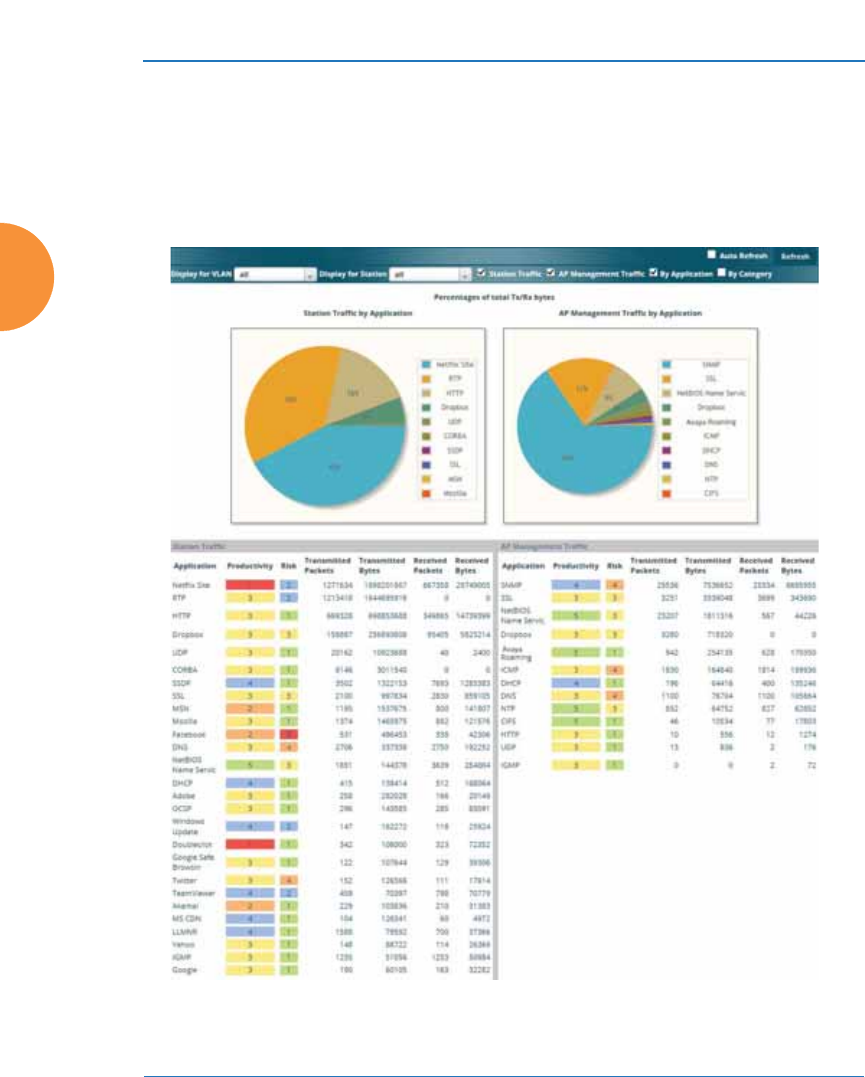
Wireless Access Point
152 Viewing Status on the Wireless AP
Application Control
This display-only window provides a snapshot of the application usage on your
AP. In order to view the Application Control window, the AP must have a license
that supports this feature, and you must have enabled the Application Control
option on the Filter Lists page (see “Filter Lists” on page 392).
Figure 91. Application Control

Wireless Access Point
Viewing Status on the Wireless AP 153
The Application Control window has three sections:
z
Selection Criteria allow you to choose the type of data to show, and to
filter for a single VLAN or station.
z
Pie Charts present a color coded at-a-glance view of the top ten
applications being used by the network.
z
Traffic Tables beneath the pie charts list the applications in use along
with traffic statistics. Unique Productivity and Risk ratings let you easily
assess the nature of applications in use, so that you can take action using
Filter Management.
Selection Criteria
At the top of the window, the options in the gray ribbon allow you to customize
the display with the following choices:
z
Display for VLAN: Use the drop-down list if you wish to select just one
VLAN to analyze, or leave the default value of all to see data from all
VLANs.
z
Display for Station: Use the drop-down list if you wish to select just one
station to analyze (stations are listed by their MAC address), or leave the
default value of all to see data from all stations. You may also use the
Stations window to select a station to display. See “Stations (Application
Control)” on page 156.
z
Station Traffic: Check this box if you wish to analyze traffic from stations,
listing the applications that they are using.
z
AP Management Traffic: Check this box if you wish to analyze
management traffic on this AP, including the load due to functions such
as Xirrus Roaming. Tracking traffic into the AP on the management side
can alert you to nefarious activity—and even to traffic on the wired
network that would best be blocked before it hits the AP. You may
display both station and AP management traffic, if you wish.
z
By Application: Check this box if you wish to analyze and list traffic by
what specific applications are in use, such as WebEx or BitTorrent.
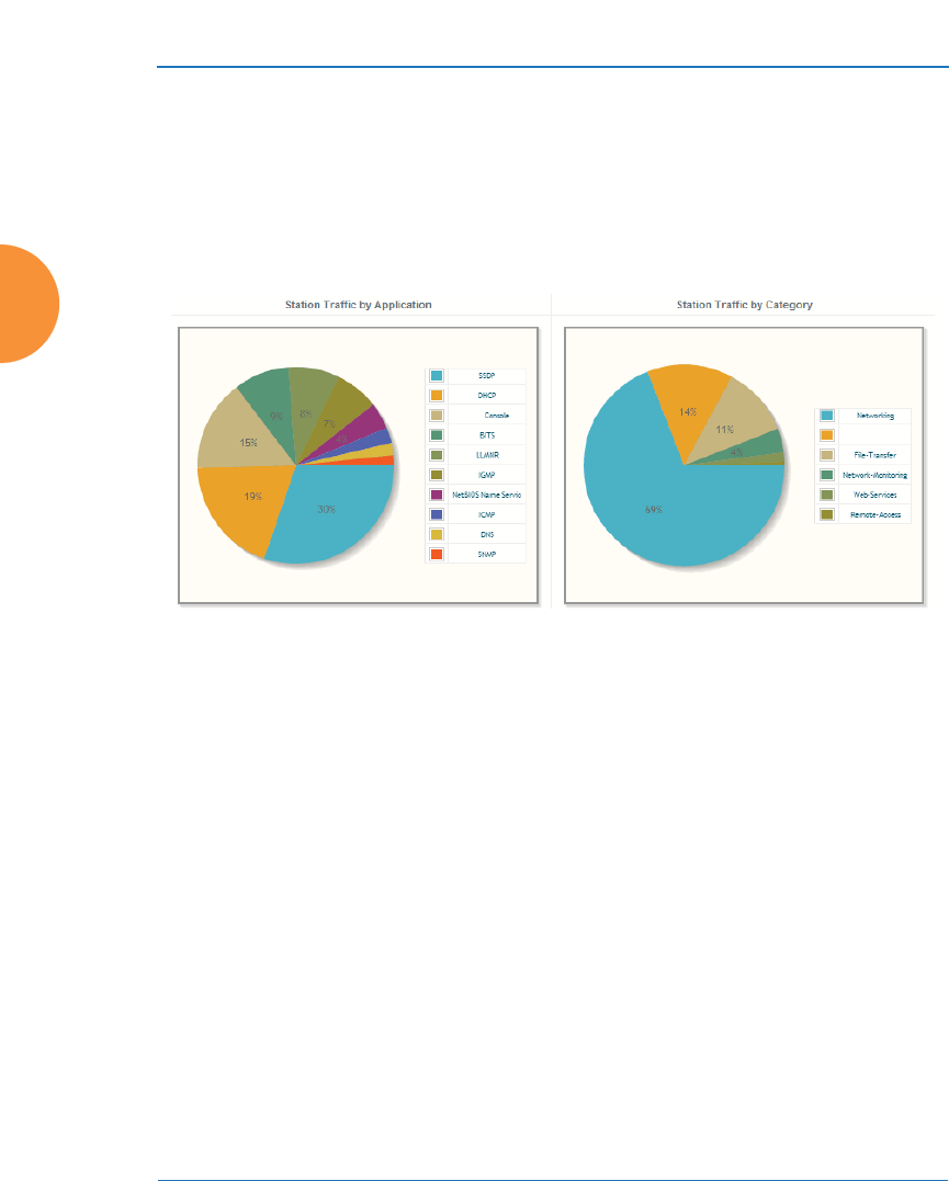
Wireless Access Point
154 Viewing Status on the Wireless AP
z
By Category: Check this box if you wish to analyze and list traffic by the
types of applications in use, such as Games or Collaboration.
z
Auto Refresh instructs the AP to periodically refresh this window
automatically. Use the Refresh button to refresh the window right now.
Pie Charts
Figure 92. Application Control (Pie Charts)
These charts provide a quick way to determine how your wireless bandwidth is
being used. There are charts for Station Traffic and/or AP Management Traffic,
depending on which checkboxes you selected. Similarly, there are charts for By
Application and/or By Category, depending on your selections. The top ten
applications or categories are listed, by percentage of bandwidth usage.

Wireless Access Point
Viewing Status on the Wireless AP 155
Traffic Tables
Figure 93. Application Control (Station Traffic)
These tables provide detailed information about how your wireless bandwidth is
being used. There are tables for Station Traffic and/or AP Management Traffic,
depending on which checkboxes you selected. Similarly, there are tables for By
Application and/or By Category, depending on your selections.
In addition to showing traffic statistics, there are two unique and highly useful
columns. Risk estimates the likelihood of an application causing problems for
your business, such as a file-sharing utility introducing viruses or exposing you to
legal problems. Risk is rated from 1 (low risk: for example, Google) to 5 (high risk:
for example, BitTorrent). Risky applications (rated at 4 or 5) are flagged for your
attention by highlighting the entry in pale red. Productivity estimates the value of
an activity to your business, from 1 (unproductive: for example, Y8 gaming) to 5
(productive: for example, WebEx).
You may click the heading of any column to sort based on that column. Click
again to sort in the reverse order. For instance, sort on Risk to find problem
applications, or sort on Productivity to find applications that should be given
increased or decreased handling priority.

Wireless Access Point
156 Viewing Status on the Wireless AP
When you find risky or unproductive applications consuming bandwidth on the
network, you can easily create Filters to control them. See “Filter Management”
on page 395. You may use filters to:
z
Block problematic traffic, such as BitTorrent or Y8.
z
Prioritize mission critical traffic—by increasing the QoS assigned to the
traffic. See “Understanding QoS Priority on the Wireless AP” on
page 271.
z
Lower the priority of less productive traffic—use filters to decrease the
QoS assigned to traffic for applications like YouTube and Facebook.
Stations (Application Control)
This status-only window shows client stations currently visible to the AP.
The MAC address in the first column is a link. Click on a selected station, and the
Application Control window opens with the Display for Station field set to that
station, to perform a detailed analysis of its application usage.
Figure 94. Stations (Application Control)
The rest of the fields and display options on this window (including the
Identification, Security, and Connection Info checkboxes) are as described in
“Stations” on page 127.
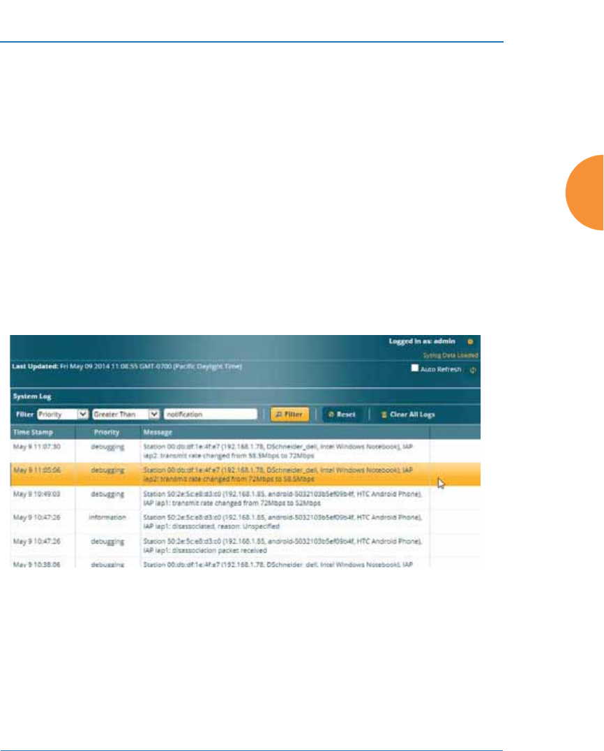
Wireless Access Point
Viewing Status on the Wireless AP 157
System Log Window
This is a status only window that allows you to review the system log, where
system alerts and messages are displayed. Although there are no configuration
options available in this window, you do have the usual choice of deciding how
the event messages are sorted by clicking in the column header for the desired
field (Time Stamp, Priority, or Message).
z
Time Stamp — sorts the list based on the time the event occurred.
z
Priority — sorts the list based on the priority assigned to the message.
z
Message — sorts the list based on the message category
The displayed messages may be filtered by using the Filter Priority option, which
allows control of the minimum priority level displayed. For example, you may
choose (under Services >System Log) to log messages at or above Debug level
but use Filter Priority to display only those at Information level and above.
Figure 95. System Log (Alert Level Highlighted)
Use the Highlight Priority field if you wish to highlight messages at the selected
priority level. Click on the Refresh button to refresh the message list, or click on
the Clear All button at the upper left to delete all messages. You can also click in
the Auto Refresh check box to instruct the AP to refresh this window
automatically.
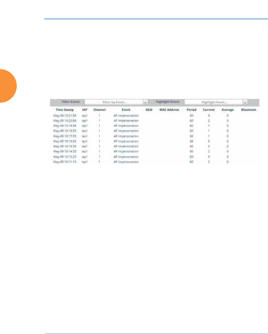
Wireless Access Point
158 Viewing Status on the Wireless AP
IDS Event Log Window
This status only window displays the Intrusion Detection System (IDS) Event log,
listing any detected attacks on your network. For descriptions of the types of
attacks detected, as well as the settings to fine-tune IDS on the AP, please see
“Intrusion Detection” on page 373.
The displayed messages may be filtered by using the Filter Event setting, which
allows you to select just one type of intrusion to display. For example, you may
choose to display only beacon flood attacks.
Figure 96. IDS Event Log
Use the Highlight Event field if you wish to highlight all events of one particular
type in the list. Click on a column header to sort the rows based on that column.
Click on the Refresh button to refresh the message list, or click the Auto Refresh
check box to instruct the AP to refresh this window automatically.
Although there are no configuration options available in this window, you do
have the usual choice of deciding how the event messages are sorted by clicking
in the column header for the desired field.
z
Time Stamp — the time that the event occurred.
z
IAP — the affected radio.
z
Channel — the affected channel.
z
Event — the type of attack, as described in Intrusion Detection.
z
SSID — the SSID that was attacked.
z
MAC Address — the MAC address of the attacker.

Wireless Access Point
Viewing Status on the Wireless AP 159
z
Period — the length of the window used to determine whether the count
of this type of event exceeded the threshold.
z
Current — the count of this type of event for the current period.
z
Average — the average count per period of this type of event.
z
Maximum — the maximum count per period of this type of event.

Wireless Access Point
160 Viewing Status on the Wireless AP

Wireless Access Point
Configuring the Wireless AP 161
Configuring the Wireless AP
The following topics include procedures for configuring the AP using the
product’s embedded Web Management Interface (WMI). Procedures have been
organized into functional areas that reflect the flow and content of the WMI. The
following WMI windows allow you to establish configuration parameters for
your AP, and include:
z
“Express Setup” on page 163
z
“Network” on page 169
z
“Services” on page 185
z
“VLANs” on page 213
z
“Tunnels” on page 220
z
“Security” on page 225
z
“SSIDs” on page 268
z
“Groups” on page 304
z
“IAPs” on page 311
z
“WDS” on page 385
z
“Filters” on page 391
z
“Clusters” on page 401
z
“Mobile” on page 406
After making changes to the configuration settings of an AP you must click the
Save button at the top of the configuration window, otherwise the changes
you make will not be applied the next time the AP is rebooted.
#If you are a customer using XMS-9000-CL-x, then APs are managed via the
Cloud, and local AP management interfaces are inaccessible.
#Some pages or individual settings are only available if the AP’s license
includes appropriate features. If a setting is unavailable (grayed out), then
your license or your AP model does not support the feature. See “About
Licensing and Upgrades” on page 412.

Wireless Access Point
162 Configuring the Wireless AP
This chapter only covers using the configuration windows on the AP. To view
status or use system tools on the AP, please see:
z
“Viewing Status on the Wireless AP” on page 95
z
“Using Tools on the Wireless AP” on page 411
#If you have added modular IAPs to your AP, note that its model number will
be automatically adjusted to reflect the count and types of IAPs currently
installed. See Upgrading with 802.11ac radio modules.
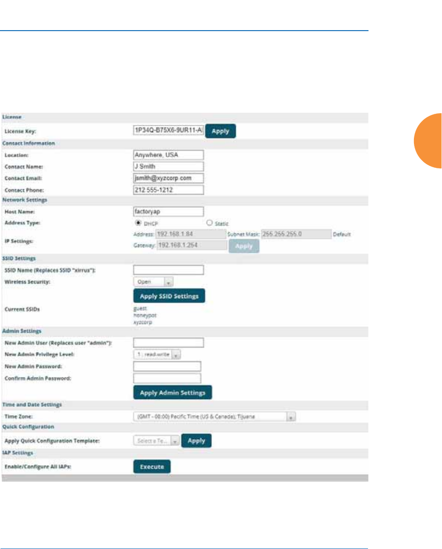
Wireless Access Point
Configuring the Wireless AP 163
Express Setup
Initial AP configuration via XMS sets items such as SSIDs and security, as
described in “Zero-Touch Provisioning and Ongoing Management” on page 75.
This page allows you to see many of these values, or change them locally.
Figure 97. WMI: Express Setup

Wireless Access Point
164 Configuring the Wireless AP
When finished, click the Save button if you wish to make your changes
permanent.
Procedure for Performing an Express Setup
1. License Key: An unlicensed AP will automatically contact Xirrus to
obtain its license, if it has Internet connectivity. If you need to enter a
license manually, enter it here. The factory installed license key is listed
here. See “Licensing” on page 80.
2. Configure the Contact Information settings.
a. Location: Enter a brief but meaningful description that accurately
defines the physical location of the AP. In an environment where
multiple units are installed, clear definitions for their locations are
important if you want to identify a specific unit.
b. Contact Name: Enter the name and contact information of the person
who is responsible for administering the AP at the designated
location.
c. Contact Email: Enter the email address of the admin contact you
entered in Step 3.
d. Contact Phone: Enter the telephone number of the admin contact you
entered in Step 3.
3. Configure the Network settings. Please see “Interfaces” on page 170 for
more information.
a. Host Name: Specify a unique host name for this AP. The host name is
used to identify the AP on the network. Use a name that will be
meaningful within your network environment, up to 64
alphanumeric characters. The default is the AP’s serial number.
b. Address Type: Choose DHCP to instruct the AP to use DHCP to
assign IP addresses to the AP’s Ethernet interfaces, or choose Static if
you intend to enter IP addresses manually. If you choose the Static IP
option, you must enter the following IP Settings:

Wireless Access Point
Configuring the Wireless AP 165
c. IP Settings: If you choose the Static IP addressing option, enter the
following:
•Address: Enter a valid IP address for this AP. To use a remote
connection (Web, SNMP, or SSH), a valid IP address must be
used.
•Subnet Mask: Enter a valid IP address for the subnet mask (the
default is 255.255.255.0). The subnet mask defines the number of
IP addresses that are available on the routed subnet where the AP
is located.
•Default Gateway: Enter a valid IP address for the default
gateway. This is the IP address of the router that the AP uses to
forward data to other networks.
•Click the Apply button for this interface when done making IP
changes.
4. SSID Settings: This section specifies the wireless network name and
security settings.
a. SSID Name is a unique name that identifies a wireless network. The
default SSID is xirrus. Entering a value in this field will replace the
this default SSID with the new name.
For additional information about SSIDs, go to the Multiple SSIDs
section of “Frequently Asked Questions” on page 522.
b. Wireless Security: Select the desired wireless security scheme (Open,
WEP or WPA). Make your selection from the choices available in the
pull-down list.
•Open — This option offers no data encryption and is not
recommended, though you might choose this option if clients are
required to use a VPN connection through a secure SSH utility,
like PuTTy.
#For improved security, you should also take the additional steps described in
“Securing Low Level Access to the AP” on page 81.

Wireless Access Point
166 Configuring the Wireless AP
•WEP (Wired Equivalent Privacy) — An optional IEEE 802.11
function that offers frame transmission privacy similar to a wired
network. WEP generates secret shared encryption keys that both
source and destination stations can use to alter frame bits to
avoid disclosure to eavesdroppers.
•WPA (Wi-Fi Protected Access) — A Wi-Fi Alliance standard that
contains a subset of the IEEE 802.11i standard, using TKIP or AES
as an encryption method and 802.1x for authentication. WPA is
the stronger of the two wireless security schemes.
•WPA2 (Wi-Fi Protected Access 2) — WPA2 is the follow-on
security method to WPA for wireless networks and provides
stronger data protection and network access control. It offers
Enterprise and consumer Wi-Fi users with a high level of
assurance that only authorized users can access their wireless
networks. Like WPA, WPA2 is designed to secure all versions of
802.11 devices, including 802.11a, 802.11b, 802.11g, and 802.11n,
multi-band and multi-mode.
•WPA-Both (WPA and WPA2) — This option makes use of both
WPA and WPA2.
For more information about security, including a full review of all
security options and settings, go to “Understanding Security” on
page 226.
c. WEP Encryption Key/WPA Passphrase: Depending on the wireless
security scheme you selected, enter a unique WEP key or WPA
passphrase. This field and the one below only appear if you select a
Wireless Security option other than Open.
d. Confirm Encryption Key/Passphrase: If you entered a WEP key or
WPA passphrase, confirm it here.
e. Click Apply SSID Settings when done.
f. Current SSIDs: This lists all of the currently defined SSIDs for you
(regardless of whether they are enabled or not).

Wireless Access Point
Configuring the Wireless AP 167
5. Admin Settings: This section allows you to change the default admin
username, password, and privileges for the AP. You may change the
password and leave the user name as is, but we suggest that you change
both to improve AP security.
a. New Admin User (Replaces user “admin”): Enter the name of a new
administrator user account. Be sure to record the new account name
and password, because the default admin user will be deleted! Note
that the AP also offers the option of authenticating administrators
using a RADIUS server (see “Admin Management” on page 231).
b. New Admin Privilege Level: By default, the new administrator will
have read/write privileges on the AP (i.e., the new user will be able
to change the configuration of the AP). If you wish the new account
to have different privileges, select the desired level from the drop-
down list. For more information about user privileges, please see
“Admin Privileges” on page 233. Take care to make sure to leave
yourself enough read/write privileges on at least one account to be
able to administer the AP.
c. New Admin Password: Enter a new administration password for
managing this AP. If you forget this password, you must reset the AP
to its factory defaults so that the password is reset to admin (its
default setting).
d. Confirm Admin Password: If you have entered a new administration
password, confirm the new password here.
e. Click Apply Admin Settings when done.
6. Time and Date Settings: System time is synchronized using NTP
(Network Time Protocol) by default. Use the drop-down list to select the
Time Zone.
7. Quick Configuration: This offers predefined configuration options such
as Classroom and High-Density that capture best practices from years of
field experience. If one of the options in the drop-down list is appropriate

Wireless Access Point
168 Configuring the Wireless AP
to your deployment, select it and click Apply. For example, the High-
Density option uses best practices to configure the AP for high density
settings such as lecture halls, convention centers, stadiums, etc.
8. IAP Settings:
Figure 98. LEDs are Switched On
Enable/Configure All IAPs: Click on the Execute button to enable and
auto configure all IAPs (a message displays the countdown time — in
seconds — to complete the auto-configuration task). When enabled, the
IAP’s LED is switched on.
9. Click the Save button at the upper right to make your changes
permanent, i.e., these settings will still be in effect after a reboot.
LED on
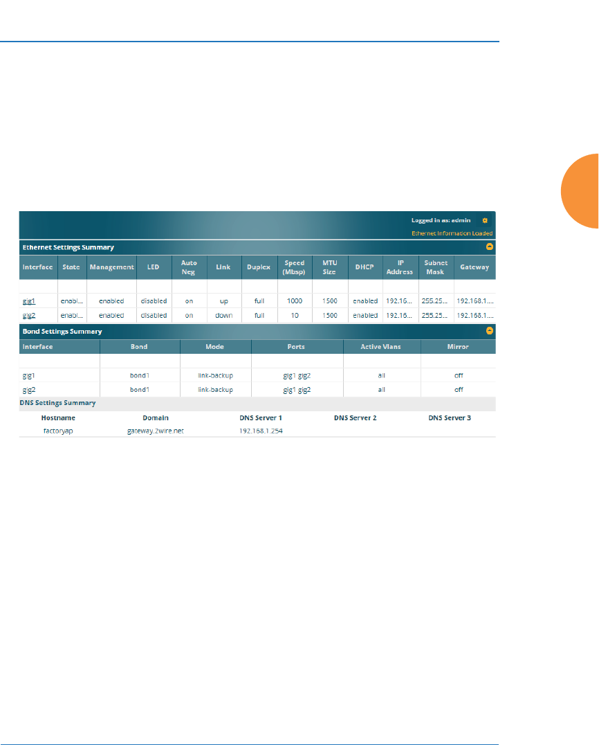
Wireless Access Point
Configuring the Wireless AP 169
Network
This is a status-only window that provides a snapshot of the configuration
settings currently established for the Ethernet interfaces. DNS Settings and other
settings are summarized as well. You must go to the appropriate configuration
window to make changes to any of the settings displayed here (configuration
changes cannot be made from this window). You can click on any item in the
Interface column to “jump” to the associated configuration window.
Figure 99. Network Interfaces
WMI windows that allow you to change or view configuration settings associated
with the network interfaces include:
z
“Interfaces” on page 170
z
“Bonds and Bridging” on page 173
z
“DNS Settings” on page 180
z
“Cisco Discovery Protocol (CDP) Settings” on page 181
z
“LLDP Settings” on page 182
See Also
DNS Settings
Interfaces
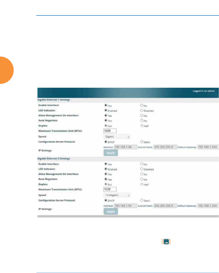
Wireless Access Point
170 Configuring the Wireless AP
Network Status Windows
Spanning Tree Status
Network Statistics
Interfaces
XR-500, XR-1000, and some XR-2000 Series APs have one Gigabit Ethernet
interface, while XR- 600, XR-4000 and some XR-2000 Series APs have two, and
XR-6000 Series models have four. This window allows you to establish
configuration settings for these interfaces.
Figure 100. Network Settings
When finished making changes, click the Save button if you wish to make
your changes permanent. When the status of a port changes, a Syslog entry is
created describing the change.

Wireless Access Point
Configuring the Wireless AP 171
Network Interface Ports
For the location of network interface ports on an AP, see the illustrations in “User
Interfaces” on page 76.
Procedure for Configuring the Network Interfaces
Configure the Gigabit network interfaces. The fields for each of these interfaces
are the same, and include:
1. Enable Interface: Choose Yes to enable this network interface, or choose
No to disable the interface.
2. LED Indicator: Choose Enabled to allow the LED for this interface to
blink with traffic on the port, or choose Disabled to turn the LED off.
The LED will still light during the boot sequence, then turn off. This
option is only available for the Gigabit interfaces.
3. Allow Management on Interface: Choose Yes to allow management of
this AP via the selected network interface, or choose No to deny all
management privileges for this interface.
4. Auto Negotiate: This feature allows the AP to negotiate the best
transmission rates automatically. Choose Yes to enable this feature, or
choose No to disable this feature — the default is enabled. If you disable
the Auto Negotiate feature, you must define the Duplex and Speed
options manually (otherwise these options are not available). Both sides
of the link must have the same values for the following settings, or the
connection will have errors.
a. Duplex: Full-duplex mode transmits data in two directions
simultaneously (for example, a telephone is a full-duplex device
because both parties can talk and be heard at the same time). Half-
duplex allows data transmission in one direction at a time only (for
example, a walkie-talkie is a half-duplex device). If the Auto-
#For improved security, you should also take the additional steps described in
“Securing Low Level Access to the AP” on page 81.

Wireless Access Point
172 Configuring the Wireless AP
Negotiate feature is disabled, you can manually choose Half or Full
duplex for your data transmission preference.
b. MTU: The Maximum Transmission Unit size. This is the largest
packet size (in bytes) that the interface can pass along.
c. Speed: If the Auto-Negotiate feature is disabled, you must manually
choose the data transmission speed from the pull-down list. For the
Gigabit interfaces the options are 10 Megabit or 100 Megabit. (Note
that 1000 Megabit speed can only be set by Auto-Negotiation.)
5. Configuration Server Protocol / IP Settings: Choose DHCP to instruct
the AP to use DHCP when assigning IP addresses to the AP, or choose
Static IP if you intend to enter IP addresses manually. If you select the
Static IP option you must specify the IP address, IP subnet mask and
default gateway.
a. Address: If you selected the Static IP option, enter a valid IP address
for the AP. To use any of the remote connections (Web, SNMP, or
SSH), a valid IP address must be established.
b. Subnet Mask: If you selected the Static IP option, enter a valid IP
address for the subnet mask (the default for Class C is 255.255.255.0).
The subnet mask defines the number of IP addresses that are
available on the routed subnet where the AP is located.
c. Default Gateway: If you selected the Static IP option, enter a valid IP
address for the default gateway. This is the IP address of the router
that the AP uses to send data to other networks. (You don’t need to
enter the gateway if it is on the same subnet as the AP.)
d. Click the Apply button for this interface when done making IP
changes.
6. When done configuring all interfaces as desired, click the Save button
if you wish to make your changes permanent.
See Also
Bonds and Bridging
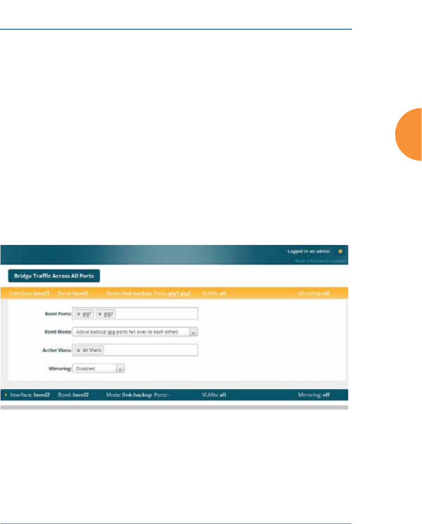
Wireless Access Point
Configuring the Wireless AP 173
DNS Settings
Network
Network Statistics
Spanning Tree Status
Bonds and Bridging
On models with more than one Gigabit port these ports may be bonded, i.e.
configured to work together in sets. For example, one port may provide active
backup or load balancing for another, or other options as described in this section.
XR-6000 Series APs have four Gigabit ports, and you may specify which ports are
bonded to work together as a pair. You may also select more than two ports to
work together in one group.
A special option lets you configure bridging between the Gigabit ports on an AP
that has two of these ports.
Figure 101. Network Bonds and Bridging
You may use the mirror option to have all the traffic that is ingressing and
egressing one bond be transmitted by the bond you are configuring. For example,
if you configure Bond2 to mirror Bond1, then all traffic going in and out of
Bond1’s Gigabit ports will be transmitted out of Bond2’s Gigabit ports. This way
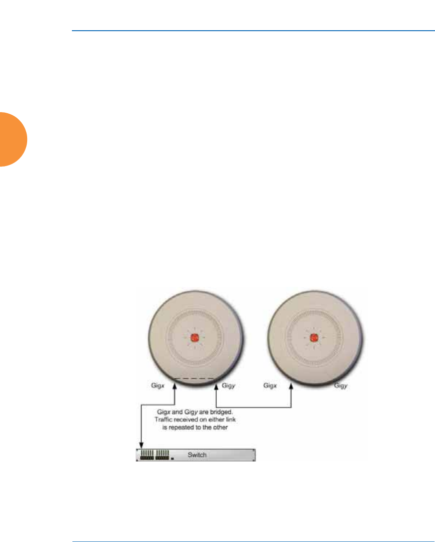
Wireless Access Point
174 Configuring the Wireless AP
of duplicating one bond’s traffic to another bond is very useful for
troubleshooting with a network analyzer.
Procedure for Configuring Network Bonds
Configure the bonding behavior of the Gigabit network interfaces. The fields for
each of these bonds are the same, and include:
1. Bridge Traffic Across All Ports: Click this for Layer 2 bridging between
all Gigabit ports. (Figure 102)
Figure 102. Bridging Traffic
#If a set of Gigabit ports have been bonded, the IP address, IP mask, IP
gateway, IP DHCP, and Management settings are shared between bonded
ports. Any changes you make to these settings on one member will be
reflected in the settings of the other members. Other settings may be
configured individually.
Bridging traffic

Wireless Access Point
Configuring the Wireless AP 175
Traffic received on Gigx is transmitted by Gigy; similarly, traffic received
on Gigy is transmitted by Gigx. The AP acts as a wired bridge—this
allows APs to be chained and still maintain wired connectivity.
When bridging is enabled, it configures the following bond settings for
each bond. Do not make any manual changes to these settings afterwards
if you wish to continue bridging.
•Bond Mode is set to Active Backup (the default value).
•Each port is in its own bond, by itself.
•Bond Mirror is Off.
•You will typically need to enable use of Spanning Tree manually, to
prevent network loops.
•Active VLANs is set to All.
A bridge between ports Gig1 and Gig2 sets Bond1 to contain only Gig1.
Bond2 contains only Gig2.
If you are bridging a chain of more than two APs, the endpoint AP is not
actually bridging. It can be left with the default settings—Bond1 is set to
Active Backup, and will contain Gig1 and Gig2.
Skip to Step 7 on page 179.
2. If you are not enabling bridging, configure the bonding behavior of the
Gigabit network interfaces as described in the following steps. The fields
for each of these bonds are the same.
3. Bond Mode: Select the desired behavior for a set of bonded Gigabit
Ethernet ports from the following options.
The modes below describe the relationship between a set of Gigabit
ports—for example, load balancing or active backup. Use the Bond Ports
field to select the ports that are bonded (set in Step 4). Two or more ports
#Each AP in a chain must have power supplied to its PoE port from a
compatible power injector or powered switch port. An AP does not supply
power to another AP.
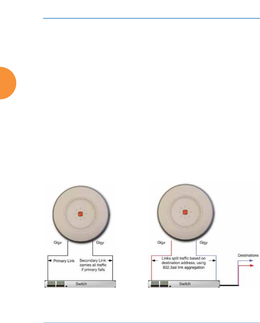
Wireless Access Point
176 Configuring the Wireless AP
may be bonded. You may also include just one single port in a bond—this
is useful for mirroring one Gigabit port to another port (Step c on
page 178). In APs that have four Gigabit ports, you have the option of
bonding three or four ports together. In this discussion, we call two ports
that are bonded Gigx and Gigy.
a. Active Backup (gig ports fail over to each other) — This mode
provides fault tolerance and is the default mode. Gigx acts as the
primary link. Gigy is the backup link and is passive. Gigy assumes
the IP properties of Gigx. If Gigx fails, the AP automatically fails over
to Gigy. When a failover occurs in this mode, Gigy issues gratuitous
ARPs to allow it to substitute for Gigx at Layer 3 as well as Layer 2.
See Figure 103 (a). You may include more than two ports in the bond
with Active Backup to provide additional fault tolerance. For
example, if you have three Gigabit ports configured in a bond, if the
first two ports in the bond were to go down, the AP would fail over
traffic to the third Gigabit port.
Figure 103. Port Modes (a, b)
(a) Active backup (b) Aggregate using 802.3ad
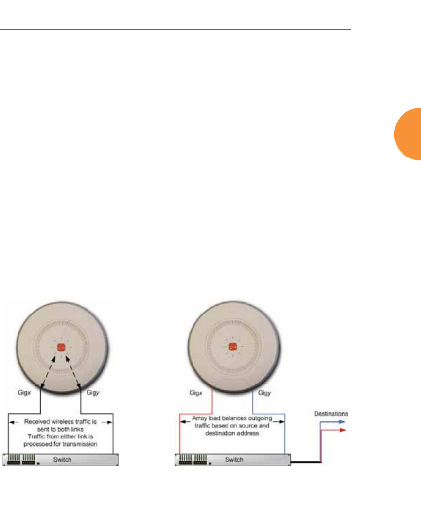
Wireless Access Point
Configuring the Wireless AP 177
b. Aggregate Traffic from gig ports using 802.3ad — The AP sends
network traffic across all member Gigabit ports to increase link speed
to the network. These ports act as a single logical interface, using a
load balancing algorithm to balance traffic across the ports. For non-
IP traffic (such as ARP), the last byte of the destination MAC address
is used to do the calculation. If the packet is a fragment or not TCP or
UDP, the source and destination IP addresses are used to do the
calculation. If the packet is TCP or UDP over IP then the source IP
address, destination IP address, source port number and destination
port number are all used to do the calculation. The network switch
must also support 802.3ad. If a port fails, the connection degrades
gracefully — the other port still transmits. See Figure 103 (b).
c. Transmit Traffic on all gig ports — Transmits incoming traffic on all
Gigabit ports. Any traffic received on Gigabit ports is sent to the
onboard processor. This mode provides fault tolerance. See
Figure 104 (c).
Figure 104. Port Modes (c, d)
(c) Transmit on all ports
(d) Load balance traffic

Wireless Access Point
178 Configuring the Wireless AP
d. Load balance traffic between gig ports — This option provides
trunking, similar to option (b) — Aggregate Traffic from gig1 & gig2
using 802.3ad, but it does not use 802.3ad and it uses a different load
balancing algorithm to determine the outgoing Gigabit port. The
outgoing port used is based on an exclusive OR of the source and
destination MAC address. Like option (b), this mode also provides
load balancing and fault tolerance. See Figure 104 (d).
4. Bond Ports: Select the ports to be members of this bond for the behavior
specified by Bond Mode. By default, Bond1 contains Gig1 and Gig2. You
may also set up a bond with a single port, for example, if you wish to
mirror one Gigabit port to another. In APs that have four Gigabit ports,
you also have the option of bonding three or four ports together.
When you check off a port to be a member of a bond, that port is
automatically removed from any other bonds that contain it.
5. Active VLANs: Active VLANs shows the VLANs that you have selected
to be passed through this port. Create and manage the list of VLANs that
are allowed to be passed through this port. Traffic will be dropped for
VLANs that are not in this list. The default setting is to pass All VLANs.
a. To add a VLAN to the list of allowed VLANs, click this field and
select the desired VLAN from the drop-down list. To allow all
VLANs (current or future) to be passed, select All VLANs.
b. To allow only the set of currently defined VLANs (see “VLANs” on
page 213) to be passed, select All Current VLANs. Essentially, this
“fixes” the Active VLANs list to contain the currently defined
VLANs, and only this set, until you make explicit changes to the
Active VLANs list. If you create new VLANs, they will not be passed
unless you take action to add them to the list.
c. To remove a VLAN from the list of allowed VLANs, click the X before
its name.
6. Mirroring — Specify one of the active bonds (Bondx) that is to be
mirrored by this bond (Bondy). (Figure 105) All wireless traffic received
on the AP is transmitted out both Bondx and Bondy. All traffic received
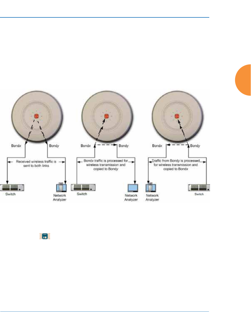
Wireless Access Point
Configuring the Wireless AP 179
on Bondx is passed on to the onboard processor as well as out Bondy. All
traffic received on Bondy is passed on to the onboard processor as well as
out Bondx. This allows a network analyzer to be plugged into Bondy to
capture traffic for troubleshooting, while the bonded ports provide
network connectivity for data traffic.
If each bond contains just one port, then you have the simple case of one
port mirroring another.
Figure 105. Mirroring Traffic
7. When done configuring bonds and bridging as desired, click the Save
button if you wish to make your changes permanent.
See Also
Interfaces
DNS Settings
Network
Network Statistics
Spanning Tree Status
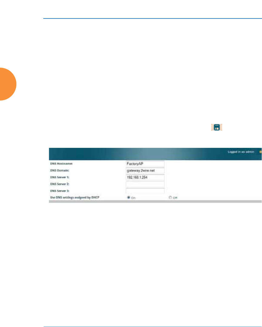
Wireless Access Point
180 Configuring the Wireless AP
DNS Settings
This window allows you to establish your DNS (Domain Name System) settings.
The AP uses these DNS servers to resolve host names into IP addresses. The AP
also registers its own Host Name with these DNS servers, so that others may
address the AP using its name rather than its IP address. An option allows you to
specify that the AP’s DNS servers will be assigned via a DHCP server on the
wired network.
Note that the DNS servers defined here are not used by wireless clients — servers
for stations associated to the AP are defined along with DHCP pools. See “DHCP
Server” on page 200. At least one DNS server must be set up if you want to offer
clients associating with the AP the ability to use meaningful host names instead of
numerical IP addresses. When finished, click the Save button if you wish to
make your changes permanent.
Figure 106. DNS Settings
Procedure for Configuring DNS Servers
1. DNS Host Name: Enter a valid DNS host name.
2. DNS Domain: Enter the DNS domain name.
3. DNS Server 1: Enter the IP address of the primary DNS server.
4. DNS Server 2 and DNS Server 3: Enter the IP address of the secondary
and tertiary DNS servers (if required).
5. Use DNS settings assigned by DHCP: If you are using DHCP to assign
the AP’s IP address, you may turn this option On. The AP will then
obtain its DNS domain and server settings from the network DHCP
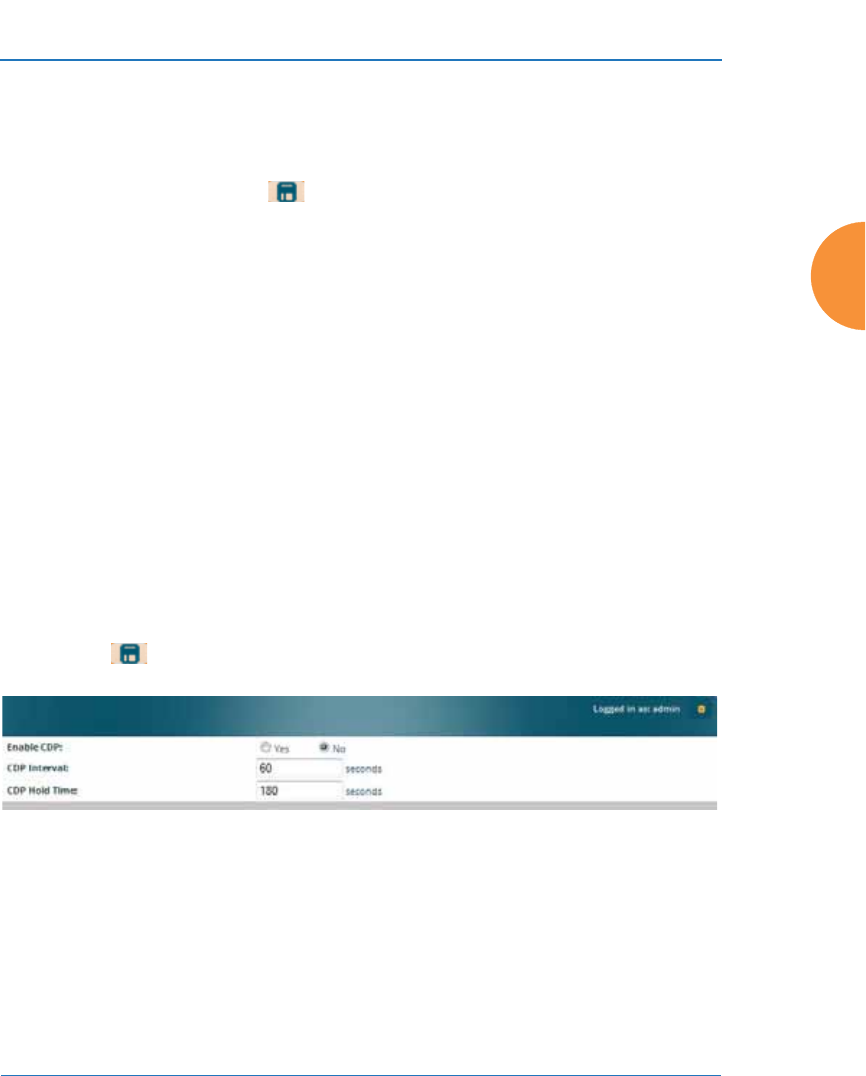
Wireless Access Point
Configuring the Wireless AP 181
server that assigns an IP address to the AP, rather than using the DNS
Server fields above. You may also configure that DHCP server to assign a
host name to the AP.
6. Click the Save button if you wish to make your changes permanent.
See Also
DHCP Server
Network
Interfaces
Network Statistics
Spanning Tree Status
Cisco Discovery Protocol (CDP) Settings
CDP is a layer 2 network protocol used to share information (such as the device
manufacturer and model, network capabilities, and IP address) with other
directly connected network devices. Wireless APs can both advertise their
presence by sending CDP announcements, and gather and display information
sent by neighbors (see “CDP List” on page 112).
This window allows you to establish your CDP settings. When finished, use the
Save button if you wish to make your changes permanent.
Figure 107. CDP Settings
Procedure for Configuring CDP Settings
1. Enable CDP: When CDP is enabled, the AP sends out CDP
announcements of the AP’s presence, and gathers CDP data sent by
neighbors. When disabled, it does neither. CDP is disabled by default.
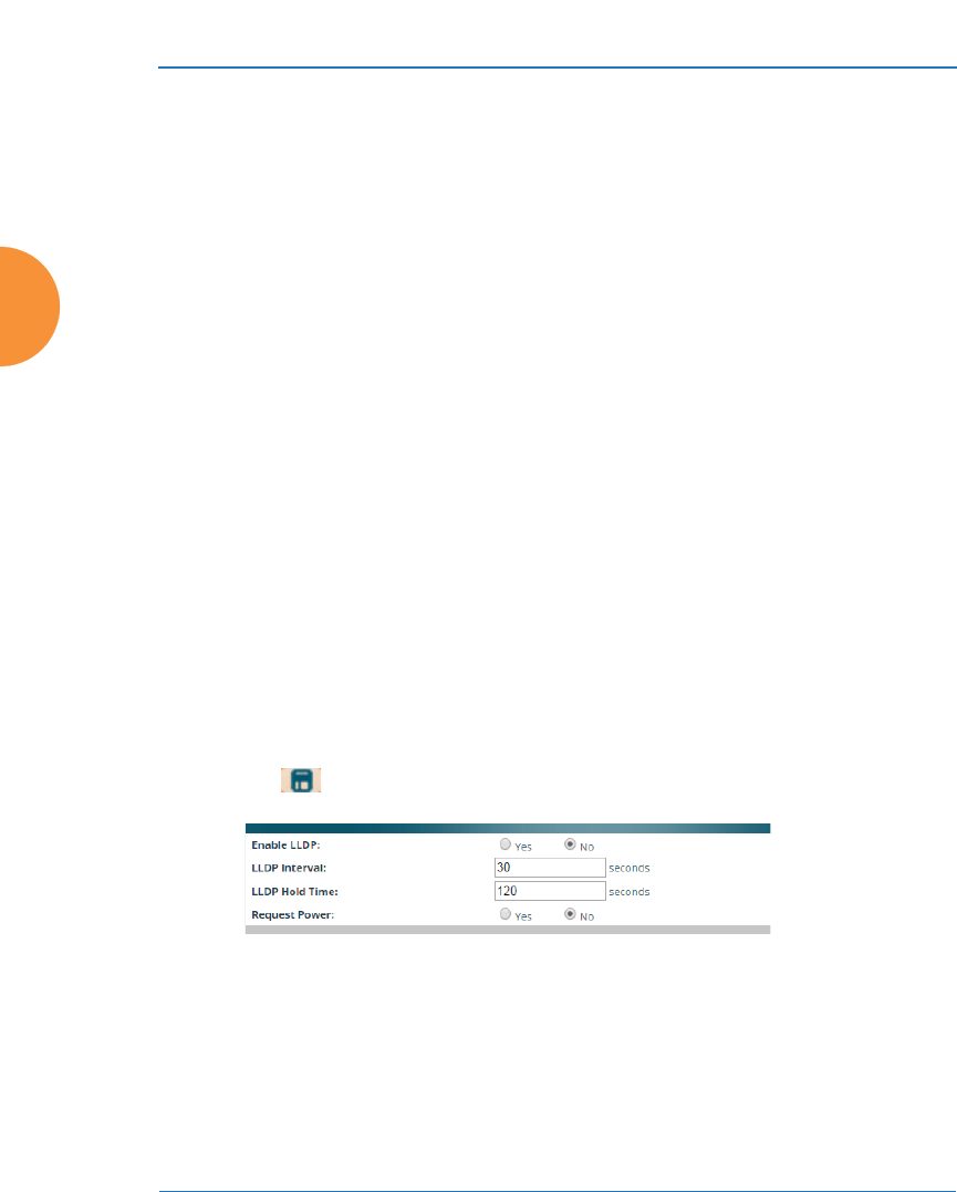
Wireless Access Point
182 Configuring the Wireless AP
2. CDP Interval: The AP sends out CDP announcements advertising its
presence at this interval. The default is 60 seconds.
3. CDP Hold Time: CDP information received from neighbors is retained
for this period of time before aging out of the AP’s neighbor list. Thus, if a
neighbor stops sending announcements, it will no longer appear on the
CDP List window after CDP Hold Time seconds from its last
announcement. The default is 180 seconds.
See Also
CDP List
Network
Interfaces
Network Statistics
LLDP Settings
Link Layer Discovery Protocol (LLDP) is a Layer 2 network protocol used to share
information (such as the device manufacturer and model, network capabilities,
and IP address) with other directly connected network devices. APs can both
advertise their presence by sending LLDP announcements, and gather and
display information sent by neighbors (see “LLDP List” on page 113).
This window allows you to establish your LLDP settings. When finished, use the
Save button if you wish to make your changes permanent.
Figure 108. LLDP Settings

Wireless Access Point
Configuring the Wireless AP 183
Procedure for Configuring LLDP Settings
1. Enable LLDP: When LLDP is enabled, the AP sends out LLDP
announcements of the AP’s presence, and gathers LLDP data sent by
neighbors. When disabled, it does neither. LLDP is disabled by default.
2. LLDP Interval: The AP sends out LLDP announcements advertising its
presence at this interval. The default is 30 seconds.
3. LLDP Hold Time: LLDP information received from neighbors is retained
for this period of time before aging out of the AP’s neighbor list. Thus, if a
neighbor stops sending announcements, it will no longer appear on the
LLDP List window after LLDP Hold Time seconds from its last
announcement. The default is 120 seconds.
4. Request Power: You must enable LLDP before enabling this feature. If
Request Power is set to Yes and LLDP discovers a device port that
supplies power to this AP (on a powered switch, for example), the AP
checks that the port is able to supply the peak power that is required by
this AP model. The Request Power feature does this by requesting this
peak power (in watts) from the PoE source, and it expects the PoE source
to reply with the amount of power allocated. If the AP does not receive a
response confirming that the power allocated by the PoE source is equal
to or greater than the power requested, then the AP issues a Syslog
message and keeps the radios down for ten minutes. The radios may be
enabled manually after this—see “IAP Settings” on page 313.
Using this feature provides a more graceful way of handling an
underpowered situation on a Wi-Fi device. When the radios are turned
off, XMS can notify you, rather than having to hunt down an intermittent
problem. This feature is disabled by default.
Request Power is available on XR-500/600 and XR-2000 models. It is
especially useful for XR-2000 models ending in 5 or 6 (except for the XR-
2435/2436), since these models draw PoE+ power levels. Some of these
models use Request Power to draw higher power than the IEEE 802.3at
maximum of 25.5W. Requested levels are:

Wireless Access Point
184 Configuring the Wireless AP
XR-2225/2226 (two 2x2 radios) = 22.5W
XR-2235/2236 (two 3x3 radios) = 26.1W
XR-2425/2426 (four 2x2 radios) = 30W
Note that Request Power is not available on the XR-2435/2436.
Additionally, it is not available on certain other APs, including these
XR Series models: XR-1000, XR-4000, XR-6000, XR-7000.
See Also
LLDP List
Network
Interfaces
Network Statistics
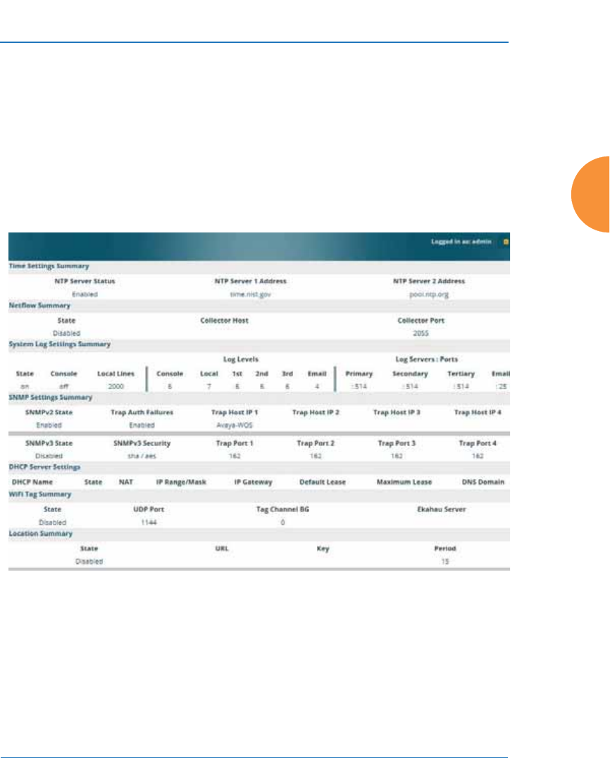
Wireless Access Point
Configuring the Wireless AP 185
Services
This is a status-only window that allows you to review the current settings and
status for services on the AP, including DHCP, SNMP, Syslog, and Network Time
Protocol (NTP) services. For example, for the DHCP server, it shows each DHCP
pool name, whether the pool is enabled, the IP address range, the gateway
address, lease times, and the DNS domain being used. There are no configuration
options available in this window, but if you are experiencing issues with network
services, you may want to print this window for your records.
Figure 109. Services
The following sections discuss configuring services on the AP:
z
“Time Settings (NTP)” on page 186
z
“NetFlow” on page 189
z
“Wi-Fi Tag” on page 190
z
“Location” on page 191
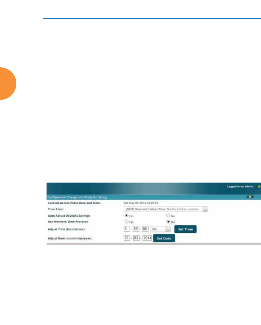
Wireless Access Point
186 Configuring the Wireless AP
z
“System Log” on page 193
z
“SNMP” on page 197
z
“DHCP Server” on page 200
z
“Proxy Services” on page 202
Time Settings (NTP)
This window allows you to manage the AP’s time settings, including
synchronizing the AP’s clock with a universal clock from an Network Time
Protocol (NTP) server. We recommend that you use NTP for proper operation of
SNMP in XMS, since a lack of synchronization will cause errors to be detected.
Synchronizing the AP’s clock with an NTP server also ensures that Syslog time-
stamping is maintained across all units.
It is possible to use authentication with NTP to ensure that you are receiving
synchronization from a known source. For example, the instructions for
requesting a key for the NIST Authenticated NTP server are available at
http://www.nist.gov/pml/div688/grp00/upload/ntp_instructions.pdf.
The AP allows you to enter optional authentication information.
Figure 110. Time Settings (Manual Time)
Procedure for Managing the Time Settings
1. Current AP Date and Time: Shows the current time.
2. Time Zone: Select the time zone you want to use (normally your local
time zone) from the pull-down list.
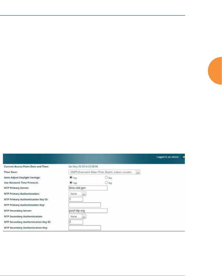
Wireless Access Point
Configuring the Wireless AP 187
3. Auto Adjust Daylight Savings: Check this box to have the system adjust
for daylight savings automatically, else leave it unchecked (default).
4. Use Network Time Protocol: Select whether to set time manually or use
NTP to manage system time.
5. Setting Time Manually
a. Adjust Time (hrs:min:sec): If you are not using NTP, use this field if
you want to adjust the current system time. Enter a revised time
(hours, minutes, seconds, am/pm) in the corresponding fields. Click
Set Time to apply the changes.
b. Adjust Date (month/day/year): If you are not using NTP, use this
field if you want to adjust the current system date. Enter a revised
date (month, day and year) in the corresponding fields. Click Set
Date to apply the changes.
6. Using an NTP Server
a. NTP Primary Server: If you are using NTP, enter the IP address or
domain name of the NTP server.
Figure 111. Time Settings (NTP Time Enabled)

Wireless Access Point
188 Configuring the Wireless AP
b. NTP Primary Authentication: (optional) If you are using
authentication with NTP, select the type of key: MD5 or SHA1. Select
None if you are not using authentication (this is the default).
c. NTP Primary Authentication Key ID: Enter the key ID, which is a
decimal integer.
d. NTP Primary Authentication Key: Enter your key, which is a string
of characters.
e. NTP Secondary Server: Enter the IP address or domain name of an
optional secondary NTP server to be used in case the AP is unable to
contact the primary server. You may use the authentication fields as
described above if you wish to set up authentication for the
secondary server.
See Also
Express Setup
Services
SNMP
System Log
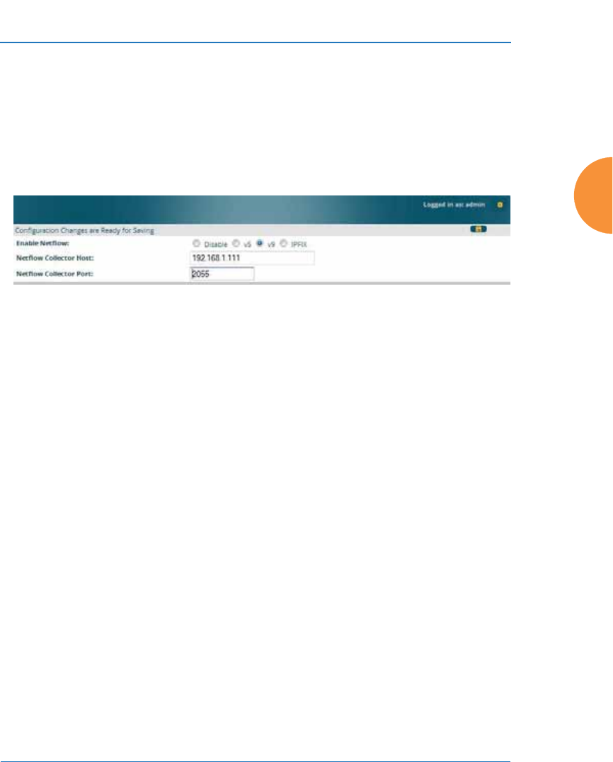
Wireless Access Point
Configuring the Wireless AP 189
NetFlow
This window allows you to enable or disable the sending of NetFlow information
to a designated collector. NetFlow is a proprietary but open network protocol
developed by Cisco Systems for collecting IP traffic information. When NetFlow
is enabled, the AP will send IP flow information (traffic statistics) to the
designated collector.
Figure 112. NetFlow
NetFlow sends per-flow network traffic information from the AP. Network
managers can use a NetFlow collector to view the statistics on a per-flow basis
and use this information to make key decisions. Knowing how many packets and
bytes are sent to and from certain IP addresses or across specific network
interfaces allows administrators to track usage by various areas. Traffic flow
information may be used to engineer networks for better performance.
Procedure for Configuring NetFlow
1. Enable NetFlow: Select one of the Netflow versions to enable NetFlow
functionality: v5, v9, or IPFIX. Internet Protocol Flow Information Export
(IPFIX) is an IETF protocol (www.ietf.org) performing many of the same
functions as Netflow. Choose Disable if you wish to disable this feature.
2. NetFlow Collector Host (Domain or IP): If you enabled NetFlow, enter
the domain name or IP address of the collector.
3. NetFlow Collector Port: If you enabled NetFlow, enter the port on the
collector host to which to send data.
#If you select IPFIX, 64 bit counters are supported starting with Release 7.1.
IPFIX uses IF-MIB, whose ifXTables support 64 bit counters.
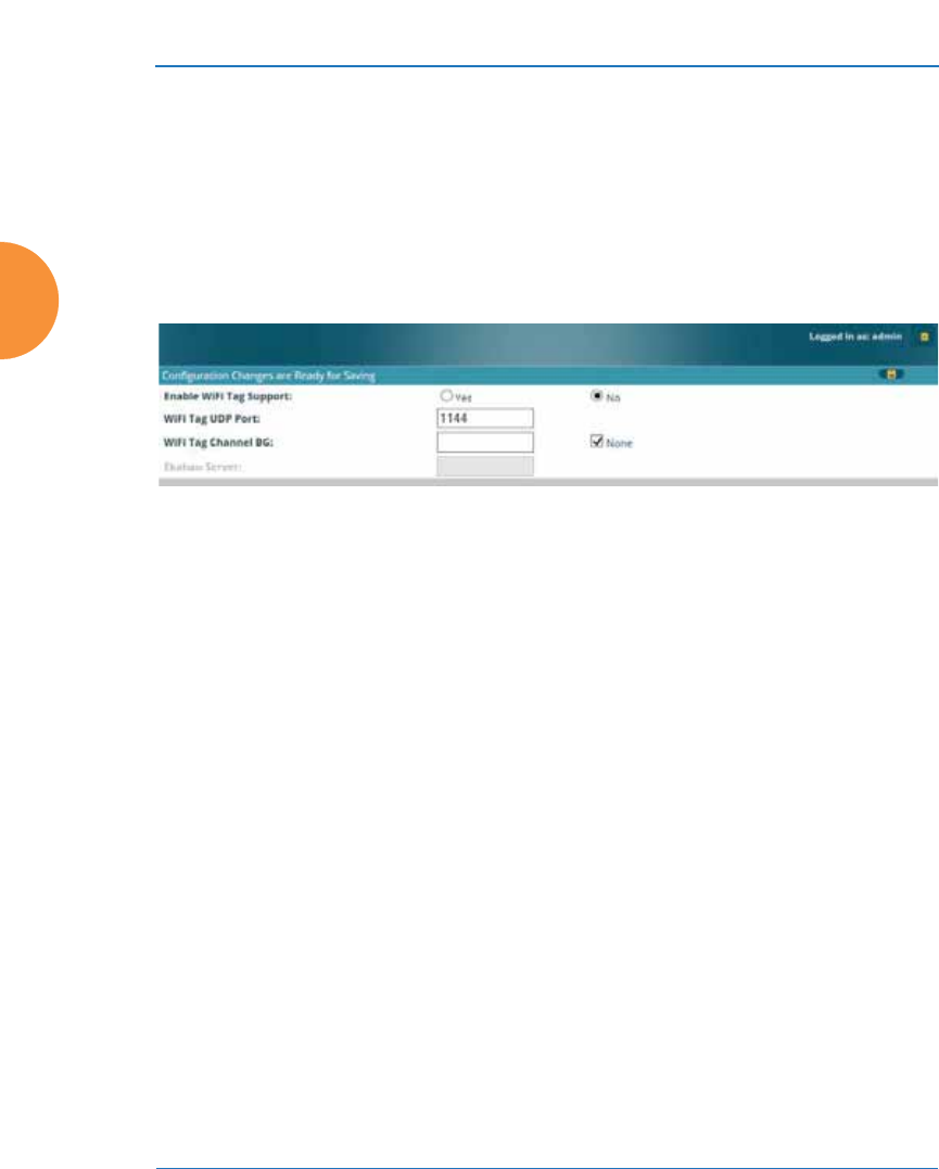
Wireless Access Point
190 Configuring the Wireless AP
Wi-Fi Tag
This window enables or disables Wi-Fi tag capabilities. When enabled, the AP
listens for and collects information about Wi-Fi RFID tags sent on the designated
channel. These tags are transmitted by specialized tag devices (for example,
AeroScout or Ekahau tags). A Wi-Fi tagging server then queries the AP for a
report on the tags that it has received. The Wi-Fi tagging server uses proprietary
algorithms to determine locations for devices sending tag signals.
Figure 113. Wi-Fi Tag
Procedure for Configuring Wi-Fi Tag
1. Enable Wi-Fi Tag: Choose Yes to enable Wi-Fi tag functionality, or choose
No to disable this feature.
2. Wi-Fi Tag UDP Port: If Wi-Fi tagging is enabled, enter the UDP port that
the Wi-Fi tagging server will use to query the AP for data. When queried,
the AP will send back information on tags it has observed. For each, the
AP sends information such as the MAC address of the tag transmitting
device, and the RSSI and noise floor observed.
3. Wi-Fi Tag Channel BG: If you enabled Wi-Fi tagging, enter the 802.11
channel on which the AP will listen for tags. The tag devices must be set
up to transmit on this channel. Only one channel may be configured, and
it must be an 802.11b/g channel in the range of Channel 1 to 11.
4. Ekahau Server: If you enabled Wi-Fi tagging and you are using an
Ekahau server, enter its IP address or hostname. Ekahau Wi-Fi Tag
packets received by the AP will be encapsulated as expected by Ekahau,
and forwarded to the server.
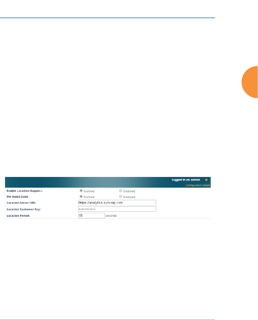
Wireless Access Point
Configuring the Wireless AP 191
Location
The AP offers an integrated capability for capturing and uploading visitor
analytics data, eliminating the need to install a standalone sensor network. This
data can be used to characterize information such as guest or customer traffic and
location, visit duration, and frequency. Use this Location window to configure the
AP to send collected data to an analytics server, such as Euclid.
When Location Support is enabled, the AP collects information about stations,
including the station ID and manufacturer, time and length of the visit and related
time interval statistics, and signal strength and its related statistics. Data collected
from stations comprises only basic device information that is broadcast by Wi-Fi
enabled devices. Devices that are only detected are included, as well as those that
actually connect to the AP. Multiple data points may be sent for a station— data is
sent for each IAP that sees a probe request from the station. The AP sending the
data also sends its own ID so that the server knows where the visitors were
detected. Data messages are uploaded via HTTPS, and they are encrypted if a
Location Customer Key has been entered. Data is sent as JSON (JavaScript Object
Notation) objects, as described in “Location Service Data Formats” on page 533.
Figure 114. Location
Procedure for Configuring Location
1. Enable Location Support: Choose Enabled to enable the collection and
upload of visitor analytic data, or choose Disabled to disable this feature.
2. Per Radio Data: Choose Enabled to enable the collection and upload of
visitor analytic data on a per-radio basis, or choose Disabled to disable
this feature.

Wireless Access Point
192 Configuring the Wireless AP
3. Location Server URL: If Location Support is enabled, enter the URL of
the location/analytics server. If this URL contains the string euclid, then
the AP knows that data is destined for a Euclid location server.
For a Euclid analytics server, use the URL that was assigned to you as a
customer by Euclid. The AP will send JSON-formatted messages in the
form required by Euclid via HTTPS.
For any other location analytics server, enter its URL. The AP will send
JSON-formatted messages in the form described in “Location Service
Data Formats” on page 533.
4. Location Customer Key: (optional) If a Location Customer Key has been
entered, data is sent encrypted using AES with that key.
5. Location Period: If you enabled Location Support, specify how often data
is to be sent to the server, in seconds.
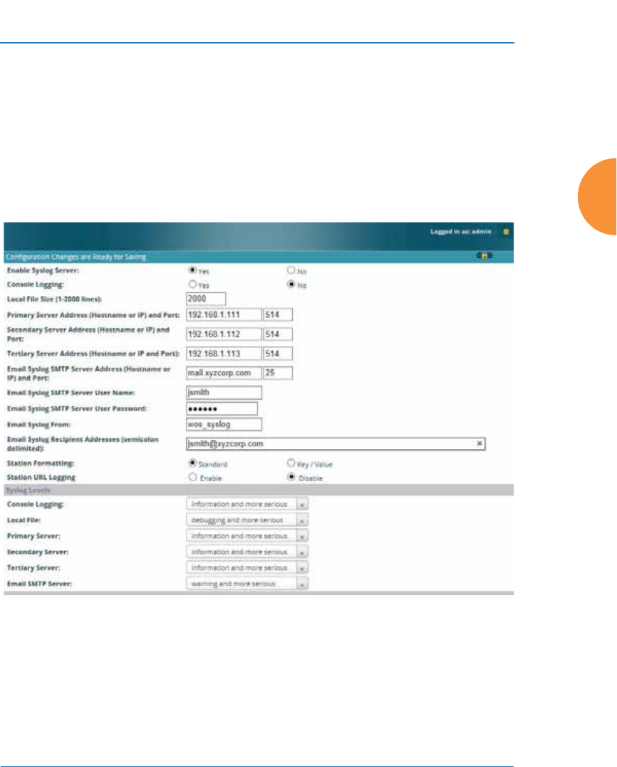
Wireless Access Point
Configuring the Wireless AP 193
System Log
This window allows you to enable or disable the Syslog server, define primary,
secondary, and tertiary servers, set up email notification, and set the level for
Syslog reporting for each server and for email notification — the Syslog service
will send Syslog messages at the selected severity or above to the defined Syslog
servers and email address. An option allows you to use a Splunk application to
analyze AP events by sending data in key:value pairs, as described in “About
Using Splunk for Xirrus APs” on page 196.
Figure 115. System Log
Procedure for Configuring Syslog
1. Enable Syslog Server: Choose Yes to enable Syslog functionality, or
choose No to disable this feature.

Wireless Access Point
194 Configuring the Wireless AP
2. Console Logging: If you enabled Syslog, select whether or not to echo
Syslog messages to the console as they occur. If you enable console
logging, be sure to set the Console Logging level (see Step 9 below).
3. Local File Size (1-2000 lines): Enter a value in this field to define how
many Syslog records are retained locally on the AP’s internal Syslog file.
The default is 2000.
4. Primary Server Address (Hostname or IP) and Port: If you enabled
Syslog, enter the hostname or IP address of the primary Syslog server.
You may also change the port used on the server if you do not wish to use
514, the default port.
5. Secondary/Tertiary Server Address (Hostname or IP) and Port:
(Optional) If you enabled Syslog, you may enter the hostname or IP
address of one or two additional Syslog servers to which messages will
also be sent. You may also change the port used on each server if you do
not wish to use 514, the default port. You may set one of the server
addresses to the address of a server for Splunk (see “About Using Splunk
for Xirrus APs” on page 196).
6. Email Notification: (Optional) The following parameters allow you to
send an email to a designated address each time a Syslog message is
generated. The email will include the text of the Syslog message.
a. Email Syslog SMTP Server Address (Hostname or IP) and Port: The
hostname or the IP address of the SMTP server to be used for sending
the email. Note that this specifies the mail server, not the email
recipient. You may also change the port used on the server if you do
not wish to use 25, the default SMTP port.
b. Email Syslog SMTP User Name: Specify a user name for logging in
to an account on the mail server designated in Step a.
c. Email Syslog SMTP User Password: Specify a password for logging
in to an account on the mail server designated in Step a.
d. Email Syslog SMTP From: Specify the “From” email address to be
displayed in the email.

Wireless Access Point
Configuring the Wireless AP 195
e. Email Syslog SMTP Recipient Addresses: Specify the entire email
address of the recipient of the email notification. You may specify
additional recipients by separating the email addresses with
semicolons (;).
7. Station Formatting: If you are sending event information to a Splunk
server, select Key/Value to send data in Splunk’s expected format,
otherwise leave this at the default value of Standard. See “About Using
Splunk for Xirrus APs” on page 196.
8. Station URL Logging: When enabled, Syslog messages are sent for each
URL that each station visits. Only HTTP destinations (port 80) are logged;
HTTPS destinations (port 443) are not logged. All URLs in a domain are
logged, so for example, if an HTTP request to yahoo.com generates
requests to 57 other URLs, all are logged. Furthermore, each visit to the
same URL generates an additional log message. No deep packet
inspection is performed by the URL logging, so no Application Control
information is included in the Syslog message.
The following information is included in the syslog message:
•Date / Time
•Source Device MAC and IP address
•Destination Port
•Destination Site address (e.g., 20.20.20.1)
•The specific URL (e.g., http://20.20.20.1.24/online/images/
img2.jpg)
Station URL Logging is disabled by default.
9. Syslog Levels: For each of the Syslog destinations, choose your preferred
level of Syslog reporting from the pull-down list. Messages with
criticality at the selected level and above will be shown. The default level
varies depending on the destination.
a. Console Logging: For messages to be echoed to the console, the
default level is Critical and more serious. This prevents large
numbers of non-critical messages from being displayed on the

Wireless Access Point
196 Configuring the Wireless AP
console. If you set this level too low, the volume of messages may
make it very difficult to work with the CLI or view other output on
the console.
b. Local File: For records to be stored on the AP’s internal Syslog file,
choose your preferred level of Syslog reporting from the pull-down
list. The default level is Debugging and more serious.
c. Primary Server: Choose the preferred level of Syslog reporting for the
primary server. The default level is Debugging and more serious.
d. Secondary/Tertiary Server: Choose the preferred level of reporting
for the secondary/tertiary server. The default level is Information
and more serious. (Optional)
e. Email SMTP Server: Choose the preferred level of Syslog reporting
for the email notifications. The default level is Warning and more
serious. This prevents your mailbox from being filled up with a large
number of less severe messages such as informational messages.
10. Click the Save button if you wish to make your changes permanent.
About Using Splunk for Xirrus APs
Splunk may be used to provide visibility into client experience and analyze usage
on APs. A Splunk application has been developed to present this operational
intelligence at a glance. The app includes field extractions, event types, searches
and dashboards to help shine a light on station status and activity
To use Splunk, set up your Splunk server with the Splunk application—available
from apps.splunk.com at Splunk for Xirrus XR Wireless APs. Configure the AP
to send data to Splunk by setting a Primary, Secondary, or Tertiary Server
Address to the IP address or hostname of your Splunk server. Then set Station
Formatting to Key/Value to send data in Splunk’s expected format.
You may specify Server Addresses for Syslog servers and a Splunk server on the
same AP. Selecting the Key/Value option will not cause any problems with
Syslog.
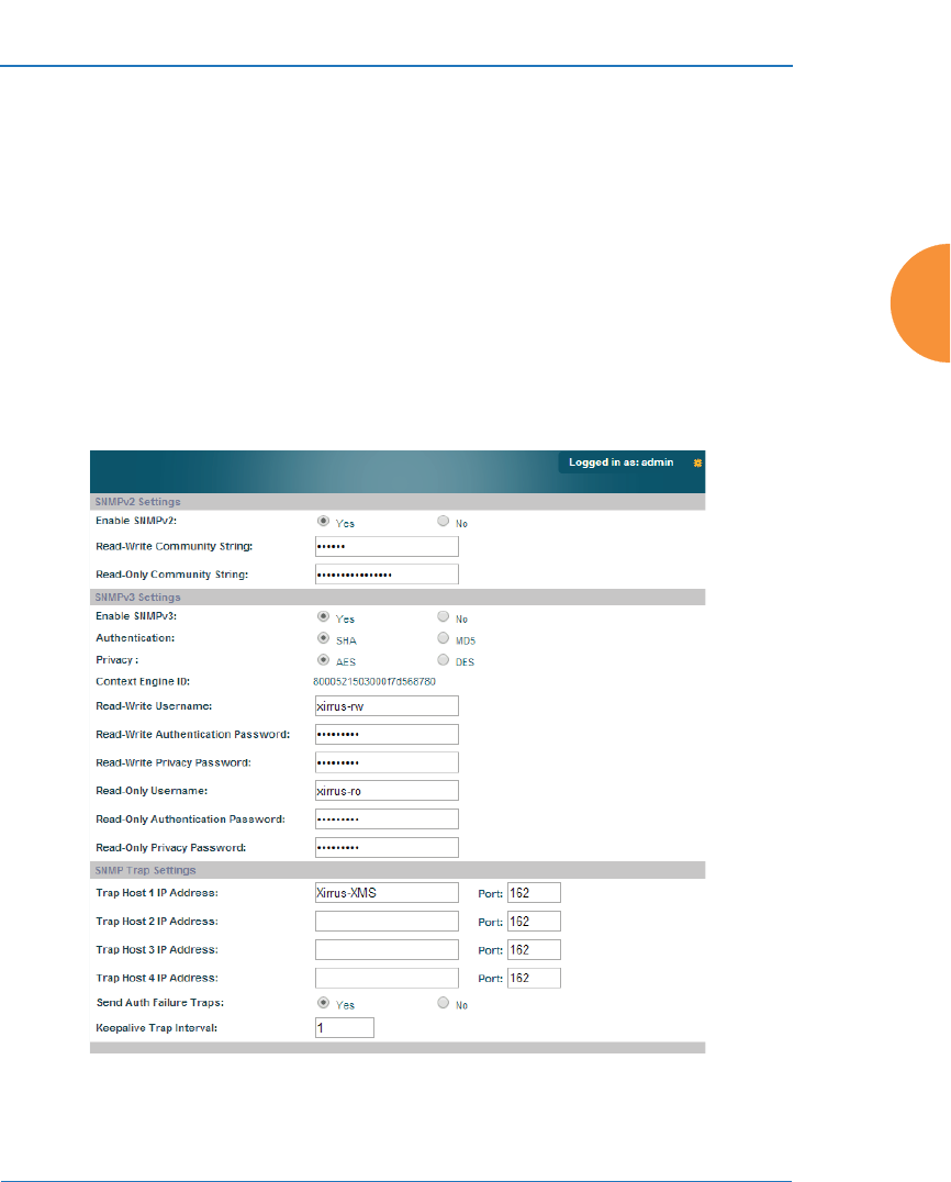
Wireless Access Point
Configuring the Wireless AP 197
See Also
System Log
Services
SNMP
Time Settings (NTP)
SNMP
This window allows you to enable or disable SNMP v2 and SNMP v3 and define
the SNMP parameters. SNMP allows remote management of the AP by the XMS
and other SNMP management tools. SNMP v3 was designed to offer much
stronger security. You may enable either SNMP version, neither, or both.
Figure 116. SNMP

Wireless Access Point
198 Configuring the Wireless AP
Complete SNMP details for the AP, including trap descriptions, are found in the
Xirrus MIB, available at support.xirrus.com, in the Downloads section (login is
required to download the MIB).
NOTE: If you are managing your APs with XMS (the Xirrus Management System), it
is very important to make sure that your SNMP settings match those that you have
configured for XMS. XMS uses both SNMP v2 and v3.
Procedure for Configuring SNMP
SNMPv2 Settings
1. Enable SNMPv2: Click the checkbox to the left of the Enabled label to
enable or disable SNMP v2 functionality. When used in conjunction with
the Xirrus Management System, SNMP v2 (not SNMP v3) must be
enabled on each AP to be managed with XMS. The default for this feature
is Enabled.
2. SNMP Read-Write Community String: Enter the read-write community
string. The default is xirrus.
3. SNMP Read-Only Community String: Enter the read-only community
string. The default is xirrus_read_only.
SNMPv3 Settings
4. Enable SNMPv3: Click the checkbox to the left of the Enabled label to
enable or disable SNMP v3 functionality. The default for this feature is
Disabled.
5. Authentication: Select the desired method for authenticating SNMPv3
packets: Secure Hash Algorithm (SHA) or Message Digest Algorithm 5
(MD5).
6. Privacy: Select the desired method for encrypting data: Data Encryption
Standard (DES) or the stronger Advanced Encryption Standard (AES).

Wireless Access Point
Configuring the Wireless AP 199
7. Context Engine ID: The unique identifier for this SNMP server. We
recommend that you do not change this value. The Context Engine ID
must be set if data collection is to be done via a proxy agent. This ID helps
the proxy agent to identify the target agent from which data is to be
collected.
8. SNMP Read-Write Username: Enter the read-write user name. This
username and password allow configuration changes to be made on the
AP. The default is xirrus-rw.
9. SNMP Read-Write Authentication Password: Enter the read-write
password for authentication (i.e., logging in). The default is xirrus-rw.
10. SNMP Read-Write Privacy Password: Enter the read-write password for
privacy (i.e., a key for encryption). The default is xirrus-rw.
11. SNMP Read-Only Username: Enter the read-only user name. This
username and password do not allow configuration changes to be made
on the AP. The default is xirrus-ro.
12. SNMP Read-Only Authentication Password: Enter the read-only
password for authentication (i.e., logging in). The default is xirrus-ro.
13. SNMP Read-Only Privacy Password: Enter the read-only password for
privacy (i.e., a key for encryption). The default is xirrus-ro.
SNMP Trap Settings
14. SNMP Trap Host IP Address: Enter the IP Address or hostname, as well
as the Port number, of an SNMP management station that is to receive
SNMP traps. You may specify up to four hosts that are to receive traps.
Note that by default, Tra p Host 1 sends traps to Xirrus-XMS. Thus, the
AP will automatically communicate its presence to XMS (as long as the
network is configured correctly to allow this host name to be resolved —
note that DNS is not normally case-sensitive).
For a definition of the traps sent by Xirrus Wireless APs, you may
download the Xirrus MIB from support.xirrus.com (login required).
Search for the string TRAP in the MIB file.
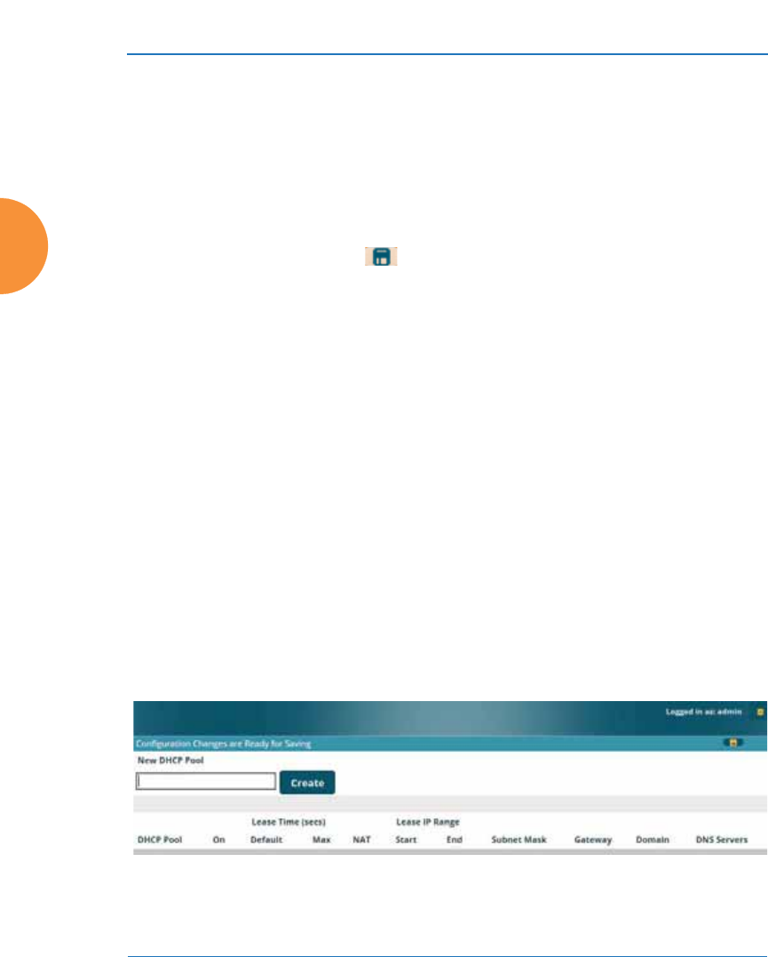
Wireless Access Point
200 Configuring the Wireless AP
15. Send Auth Failure Traps: Click the checkbox to the left of the Enabled
label to enable or disable log authentication failure traps.
16. Keepalive Trap Interval (minutes): Traps are sent out at this interval to
indicate the presence of the AP on the network. Keepalive traps are
required for proper operation with XMS. To disable keepalive traps, set
the value to 0.
17. Click the Save button if you wish to make your changes permanent.
See Also
Services
System Log
Time Settings (NTP)
DHCP Server
This window allows you to create, enable, modify and delete DHCP (Dynamic
Host Configuration Protocol) address pools. DHCP allows the AP to provide
wireless clients with IP addresses and other networking information. The DHCP
server will not provide DHCP services to the wired side of the network. If you do
not use the DHCP server on the AP, then your wired network must be configured
to supply DHCP addresses and gateway and DNS server addresses to wireless
clients.
When you create a DHCP pool, you must define the DHCP lease time (default
and maximum), the IP address ranges (pools) that the DHCP server can assign,
and the gateway address and DNS servers to be used by clients.
Figure 117. DHCP Management

Wireless Access Point
Configuring the Wireless AP 201
DHCP usage is determined in several windows — see SSID Management, Group
Management, and VLAN Management.
Procedure for Configuring the DHCP Server
1. New Internal DHCP Pool: Enter a name for the new DHCP pool, then
click on the Create button. The new pool ID is added to the list of
available DHCP pools. You may create up to 16 DHCP pools (up to 8 on
the XR-500 Series).
2. On: Click this checkbox to make this pool of addresses available, or clear
it to disable the pool.
3. Lease Time — Default: This field defines the default DHCP lease time (in
seconds). The factory default is 300 seconds, but you can change the
default at any time.
4. Lease Time — Max: Enter a value (in seconds) to define the maximum
allowable DHCP lease time. The default is 300 seconds.
5. Network Address Translation (NAT): Check this box to enable the
Network Address Translation feature. The NATed address uses the IP
address of the AP’s outbound gigabit Ethernet interface.
6. Lease IP Range — Start: Enter an IP address to define the start of the IP
range that will be used by the DHCP server. The default is 192.168.1.100.
7. Lease IP Range — End: Enter an IP address to define the end of the IP
range that will be used by the DHCP server. The DHCP server will only
use IP addresses that fall between the start and end range that you define
on this page. The default is 192.168.1.200.
8. Subnet Mask: Enter the subnet mask for this IP range for the DHCP
server. The default is 255.255.255.0.
9. Gateway: If necessary, enter the IP address of the gateway.
10. Domain: Enter the DNS domain name. See “DNS Settings” on page 180.

Wireless Access Point
202 Configuring the Wireless AP
11. DNS Servers (1 to 3): Enter the IP address of the primary DNS server,
secondary DNS server and tertiary DNS server. These DNS server
addresses will be passed to stations when they associate, along with the
assigned IP address. Note that if you leave these blank, no DNS
information is sent to the stations. DHCP will not default to sending the
DNS servers that are configured in DNS Settings. See also, “DNS
Settings” on page 180.
12. Click the Save button if you wish to make your changes permanent.
See Also
DHCP Leases
DNS Settings
Network Map
Proxy Services
If your organization uses a proxy server such as Blue Coat or Netbox Blue to
control Internet access, use this page to configure proxy forwarding on the AP.
Options are provided for proxying user traffic and AP management traffic.
Proxy services for user traffic are discussed in the following topics:
z
“About Proxy Forwarding” on page 203
z
“Proxy Forwarding for HTTPS” on page 204
z
“Summary of Proxy Forwarding Behavior on the AP” on page 205
z
“Configuring Proxy Forwarding on Clients for HTTPS” on page 206
z
“Procedure for Configuring Proxy Forwarding on the AP” on page 210
Proxy services for management traffic are discussed in the following topics:
z
“About Using a Proxy Client for Management Traffic” on page 210
z
“Procedure for Configuring Proxy Client for Management Traffic” on
page 211
#XR-520/XR-1000 Series APs do not support HTTP/S proxy. You will
receive an error message if you attempt to configure this feature.
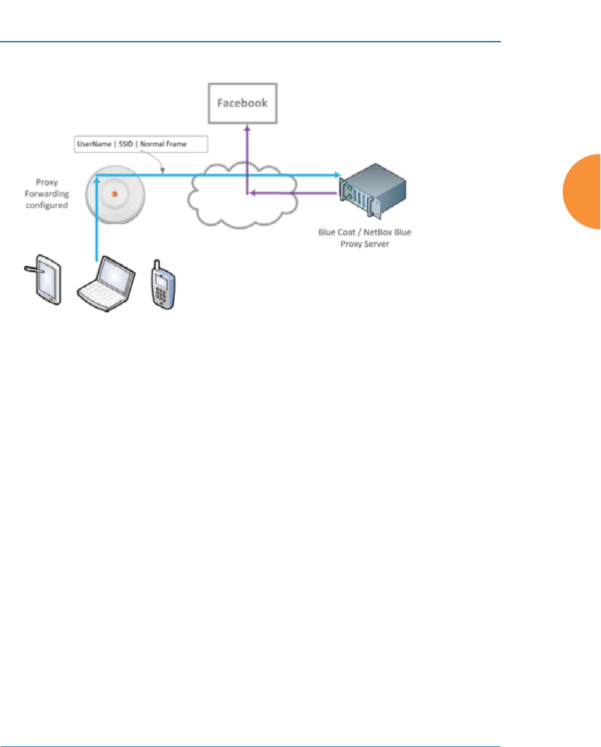
Wireless Access Point
Configuring the Wireless AP 203
About Proxy Forwarding
Figure 118. Proxy Forwarding Example
When you configure proxy forwarding settings on the AP, it forwards each HTTP
request to the proxy server (for example, Blue Coat) at the specified URL, which
checks if the policies that you have set up on the server are satisfied. If so, the
proxy server sends the request on to the desired web site. An example is shown in
Figure 118. The user of the laptop tries to open Facebook on a browser. The AP
forwards this request to the proxy server that you have specified, after adding a
prefix with the user’s ID and the SSID (the SSID serves as a user group; for
unauthenticated clients, the MAC address serves as the user name). The proxy
server checks whether its configured policies permit this access for this user and
SSID. If so, the frame is forwarded to the desired web site.
Proxy forwarding on the AP is designed for proxy servers such as Blue Coat and
Netbox Blue whose purpose is restricting Internet access to sites, applications and
content, and the monitoring and reporting of this activity. It is not used for
enhanced performance utilizing content caching.
#SSID and client User Name restrictions permit the following characters.
— Blue Coat permits only alphanumerics and + and /.
— Netbox Blue permits only alphanumerics and dot, hyphen, underscore,
and space characters.

Wireless Access Point
204 Configuring the Wireless AP
Proxy forwarding on the AP is configured as described in “Procedure for
Configuring Proxy Forwarding on the AP” on page 210. This proxies all HTTP
traffic to the specified server. If you wish to proxy HTTPS traffic as well, you must
take the additional steps described below.
Proxy Forwarding for HTTPS
There are two usage scenarios for proxy forwarding:
z
Use proxy forwarding for HTTP traffic only: set up the AP per
“Procedure for Configuring Proxy Forwarding on the AP” on page 210.
HTTPS traffic is unaffected and proceeds in the usual way.
z
Use proxy forwarding for both HTTP and HTTPS traffic: set up the AP
per “Procedure for Configuring Proxy Forwarding on the AP” on
page 210. Then you must set up browsers on client stations (laptops,
smart phones, tablets, ...) to proxy both HTTP and HTTPS traffic to the
AP. Each client must also download and install the SSL certificate from
the Blue Coat or Netbox Blue proxy server. Follow the procedure below to
perform these steps on each client. Note that when a proxy is set up and
used for HTTPS, HTTP traffic will also use the proxy server, so configure
both as instructed in “Configuring Proxy Forwarding on Clients for
HTTPS” on page 206.
#Blue Coat policy configuration:
The AuthConnector utility is not used with the Xirrus implementation.
Traffic must first be passed through the portal to dynamically add the User
to Blue Coat’s list of recognized Users, based on the User header inserted in
the packets. When configuring Blue Coat Content Filtering policy, you may
select “Users from Reporting”. Only the User value can be used in this
manner. The Group header value is not dynamically added to Blue Coat’s
Group list, and it can't be added manually.
Netbox Blue policy configuration:
Users and Groups are manually configured on the server. Users are
manually assigned to Groups, and policy is applied on a per-Group basis.

Wireless Access Point
Configuring the Wireless AP 205
Summary of Proxy Forwarding Behavior on the AP
If proxy forwarding is not enabled in the AP and the client browser is not
configured to use a proxy:
z
HTTP traffic (port 80) and HTTPS traffic (port 443) pass transparently
through the AP in the usual way.
If proxy forwarding is enabled for Blue Coat or Netbox Blue and the client
browser is not configured to use a proxy (i.e., you do not wish to proxy secure
traffic):
z
The browser still uses HTTP (port 80) and this traffic is captured and
proxied by the AP.
z
The browser still uses HTTPS (port 443) and this traffic is passed
transparently through the AP.
z
If proxy forwarding is not working correctly, HTTP traffic (port 80) is
blocked.
If proxy forwarding is enabled for Blue Coat or Netbox Blue and the client
browser is configured to use a proxy:
z
The browser is configured to proxy HTTPS to www.xirrus.com port 4388.
z
The browser automatically proxies HTTP traffic to the same port that is
used for HTTPS traffic—port 4388.
z
All HTTP/HTTPS traffic is captured by the AP and proxied to Blue Coat
or Netbox Blue per your settings.
z
If AP proxy forwarding is not working correctly (for example, if the
configuration is incorrect), all HTTP/HTTPS/4388 traffic is blocked.
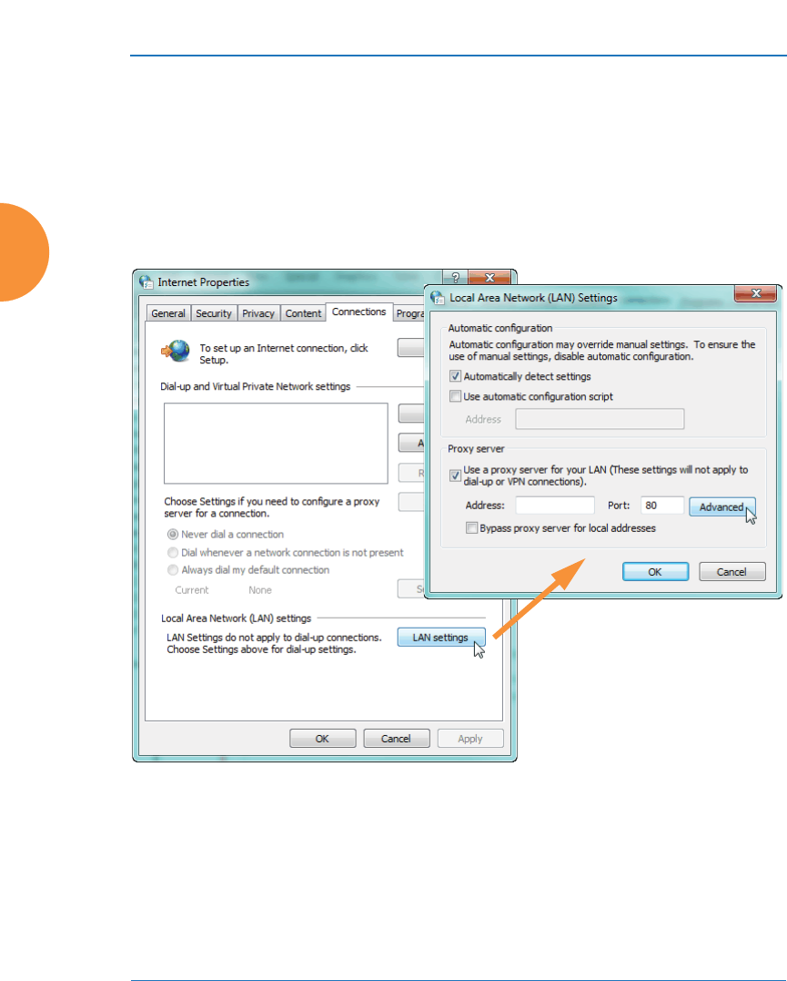
Wireless Access Point
206 Configuring the Wireless AP
Configuring Proxy Forwarding on Clients for HTTPS
To set the proxy server on an Apple laptop, skip to Step 3.
1. For Windows laptops, click the desktop Start button. In the Search
programs and files field, enter Configure proxy server. The Internet
Properties dialog is displayed. (Figure 119) Click the LAN Settings
button. The Local Area Network dialog displays.
Figure 119. Set up a Proxy Server on each Client (Windows)
2. In the Proxy Server section, click the Advanced button. The Proxy
Settings dialog displays. (Figure 120)
For HTTPS: Enter any valid address, such as your company’s web site in
the Proxy address to use field. For example, www.xyzcorp.com as shown
in Figure 116. This field is not actually used, but Windows needs it to be a
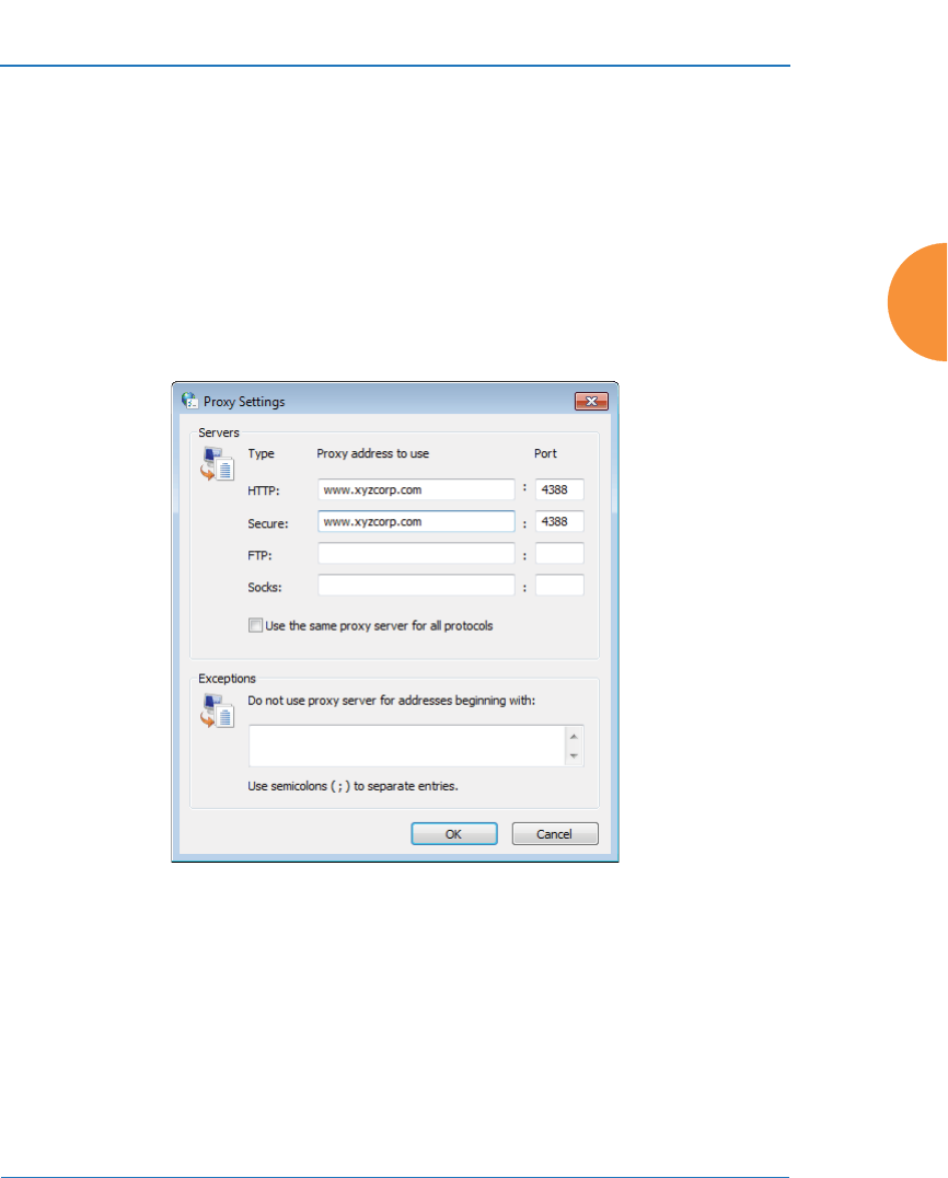
Wireless Access Point
Configuring the Wireless AP 207
valid address or domain name. You must set the Port to 4388. This is very
important! This is the AP port that should receive all HTTPS traffic if you
are using a proxy server.
For HTTP: HTTP traffic will automatically use the same port that you
have configured for HTTPS: 4388. We suggest that you enter your
company’s web site, Port 4388 here to make it obvious that HTTP traffic is
being proxied in this way.
Continue to Step 5.
Figure 120. Specify Proxy Servers (Windows)
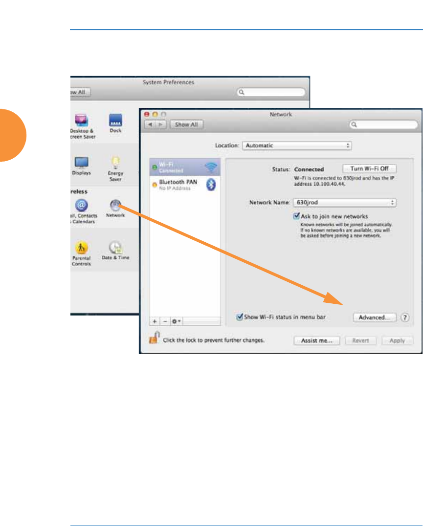
Wireless Access Point
208 Configuring the Wireless AP
3. For Apple laptops, open System Preferences and select Network. The
Network dialog is displayed. (Figure 121) Click the Advanced button.
Figure 121. Set up a Proxy Server on each Client (Apple)
4. Select the Proxies tab. (Figure 122)
Check Secure Web Proxy (HTTPS): Under Secure Web Proxy Server, you
can enter any valid address. We suggest that you enter www.xirrus.com.
(This field is not actually used, but it must be a valid address or domain
name). You must set the Port to 4388. This is very important! This is the
AP port that must receive all HTTPS traffic if you are using a proxy server
for HTTPS.
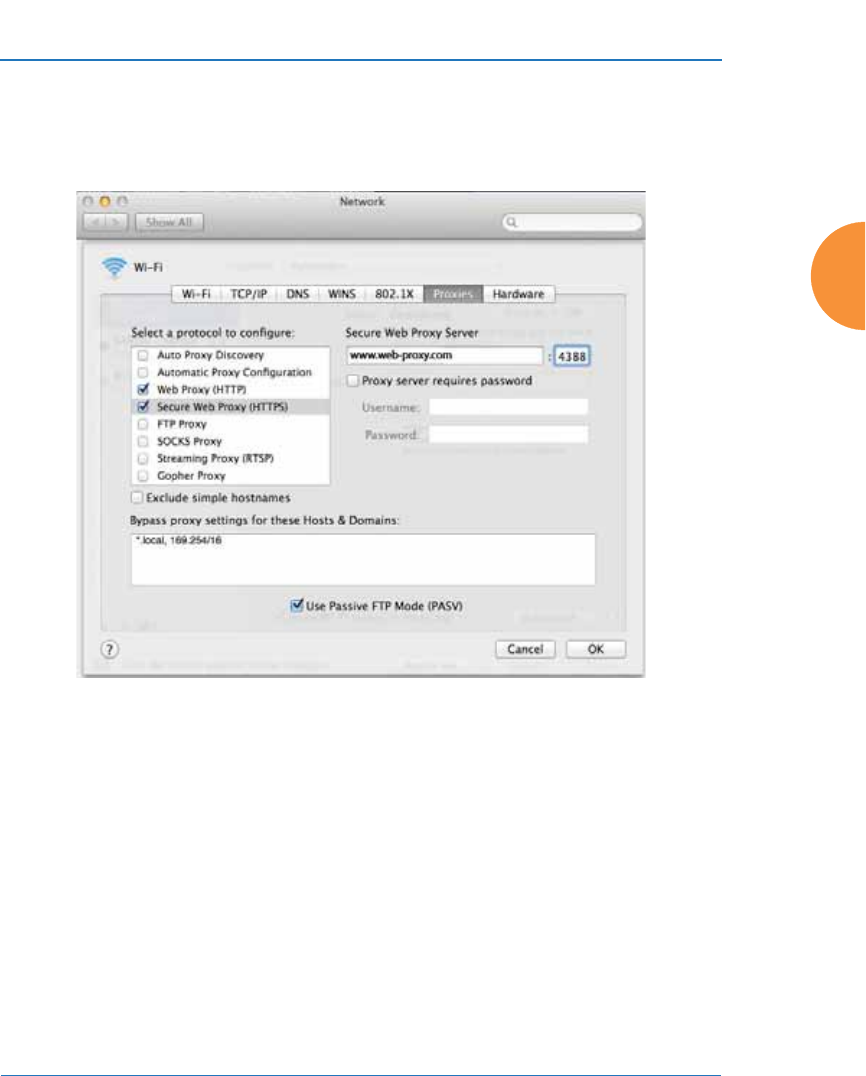
Wireless Access Point
Configuring the Wireless AP 209
Check Web Proxy (HTTP): Under Web Proxy Server, we suggest that you
enter www.xirrus.com Port 4388 to make it obvious that HTTP traffic is
being proxied in this way.
Figure 122. Specify Proxy Servers (Apple)
5. SSL Certificate: you must download and install the security certificate
from your proxy server—Blue Coat or Netbox Blue. It must be installed
on each of your client devices.
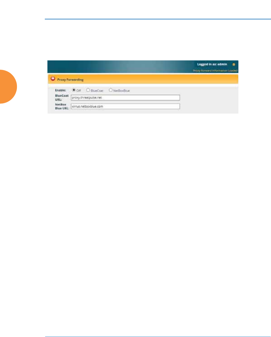
Wireless Access Point
210 Configuring the Wireless AP
Procedure for Configuring Proxy Forwarding on the AP
1. Enable: If you wish to use proxy forwarding, select the proxy server
type—Blue Coat or Netbox Blue.
Figure 123. Proxy Forwarding
2. BlueCoat URL: If you selected Blue Coat above, enter the URL of the
proxy server, for example, http://proxy.threatpulse.net.
3. Netbox Blue URL: If you selected Netbox Blue above, enter the actual
URL of the proxy server, for example, xirrus.netboxblue.com. Note that
this default URL is not an actual proxy server—this prevents you from
unintentionally forwarding traffic.
About Using a Proxy Client for Management Traffic
Some deployments require that all Internet traffic, including management traffic,
use proxy services. For instance, some school systems require all traffic to use a
proxy server. The AP generates management traffic to implement essential
functions such as licensing/activation, XMS-Cloud configuration, and XMS Guest
Access authentication. The AP allows you to configure clients that are used to
proxy such management traffic.
If your deployment requires proxying the AP’s management traffic, rather than
allowing that traffic to go directly out to the Internet, you will need to configure
the following clients:
z
HTTP and HTTPS: This traffic sends traps and fetches configurations
from XMS. If you are using the XMS-Cloud Guest Access service, this also
uses the HTTPS proxy client. You must enter the IP address and subnet
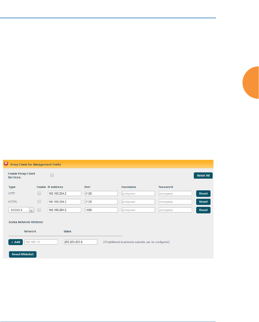
Wireless Access Point
Configuring the Wireless AP 211
mask of the proxy server. If this server requires authentication, you may
enter a user name and password as well.
z
SOCKS: Other management functions use this form of socket to send
traffic. For example, this socket is used by the XMS-Cloud configuration
service which communicates with the XMS-Cloud using web sockets.
Currently, two versions of SOCKS are broadly used on the Internet –
Version 4 and Version 5. The service defaults to Version 5 if no version is
declared.
The SOCKS proxy client requires a whitelist of networks that will not be
proxied. At the least, this must include the loopback address and the
subnet where the proxy server lives. Additional defined subnets should
include DNS servers and authentication servers.
Procedure for Configuring Proxy Client for Management Traffic
1. Enable: For each proxy client, you must Enable it if you wish to use it.
Figure 124. Proxy Client for Management Traffic
2. IP Address/Port: For each proxy client, enter the IP Address and Port of
the proxy server. For the HTTP and HTTPS proxy clients, you may
specify a fully qualified domain name (FQDN) or an IP address. For

Wireless Access Point
212 Configuring the Wireless AP
SOCKS, an FQDN is not allowed—an IP address is required. The default
Port settings are standard defaults for these ports.
3. Username/Password: For each proxy client, if the proxy server requires
authentication, enter the Username and Password here.
4. SOCKS 4/ SOCKS 5: Select the version of SOCKS in use on your proxy
server. The default is SOCKS 5.
5. Socks Network Whitelist: Enter a whitelist of subnetworks that must not
be proxied. Specify each subnet by entering its Network address and its
subnet Mask, then click Add. At the least, create entries for the loopback
address and the subnet where the proxy server lives. You should also
enter subnets that include your DNS servers and authentication servers.
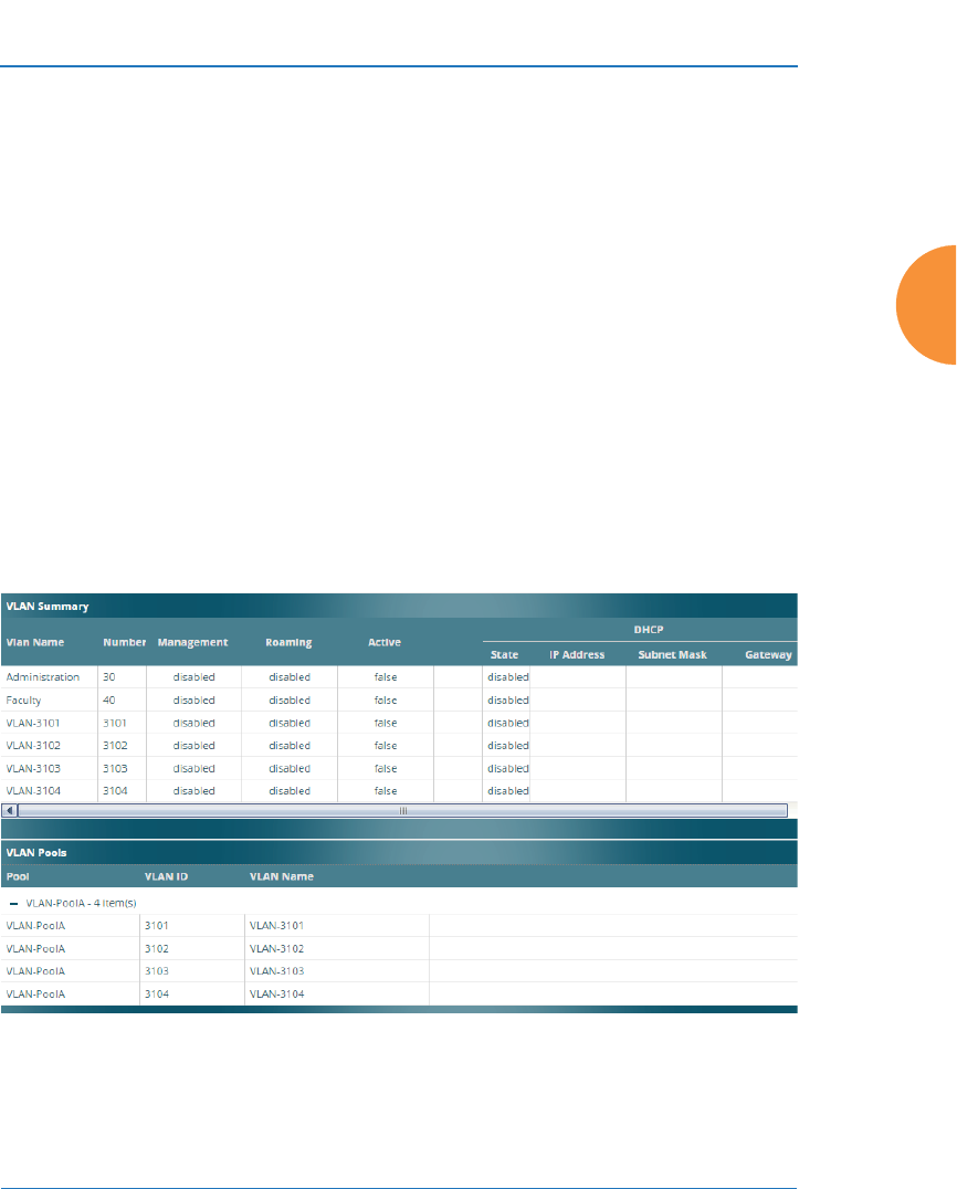
Wireless Access Point
Configuring the Wireless AP 213
VLANs
This is a status-only window that allows you to review the current status of
configured VLANs and VLAN Pools. VLANs are virtual LANs used to create
broadcast domains. VLAN pools are provided for special situations where clients
are to be assigned one of a set of VLANs that are treated as a pool. See “VLAN
Pools” on page 215.
In addition to listing all VLANs, this window shows your settings for the Default
Route VLAN and the Native (Untagged) VLAN (Step 1 page 217).
Figure 125. VLANs
#You should create VLAN entries on the AP for all of the VLANs in your
wired network if you wish to make traffic from those VLANs available on the
wireless network. Each tagged VLAN should be associated with a wireless
SSID (see “VLAN Management” on page 216). The AP will discard any
VLAN-tagged packets arriving on its wired ports, unless the same VLAN
has been defined on the AP. See “Undefined VLANs” on page 114.

Wireless Access Point
214 Configuring the Wireless AP
Understanding Virtual Tunnels
Xirrus APs support Layer 2 tunneling. This allows an AP to use tunnels to
transport traffic for one or more SSID-VLAN pairs onto a single destination
network through the Layer 3 core network. Tunnels may be implemented with:
z
The Xirrus Tunnel Server (XTS)—see the Xirrus Tunnel Server User’s Guide.
z
Virtual Tunnel Server (VTS)—see below.
You may specify a tunnel for a VLAN as described below and in “Procedure for
Managing VLANs” on page 217. These tunnels are typically set up to be
encrypted. Alternatively, the GRE tunnels created in “Tunnel Management” on
page 221 are not encrypted, offering much higher throughput and scaling better.
If tunneled traffic is not traversing public networks, GRE is recommended. While
VLAN tunnels and GRE can be used on the same AP simultaneously, more than
one tunnel shouldn't be configured to tunnel the same traffic.
Virtual Tunnel Server (VTS)
Tunneling capability is provided by a Virtual Tunnel Server. You supply the server
and deploy it in your network using open-source VTun software, available from
vtun.sourceforge.net. To enable the AP to use tunneling for a VLAN, simply enter
the IP address, port and secret for the tunnel server as described in Step 12 on
page 219.
VTun may be configured for a number of different tunnel types, protocols, and
encryption types. For use with APs, we recommend the following configuration
choices:
z
Tunnel Type: Ether (Ethernet tunnel)
z
Protocol: UDP
z
Encryption Type: select one of the encryption types supported by VTun
(AES and Blowfish options are available)
z
Keepalive: yes
VTS Client-Server Interaction
The AP is a client of the Virtual Tunnel Server. When you specify a VTS for an
active VLAN-SSID pair, the AP contacts the VTS. The server then creates a tunnel

Wireless Access Point
Configuring the Wireless AP 215
session to the AP. VTun encapsulated packets will cross the Layer 3 network from
the AP to the VTS. When packets arrive at the VTS, they will be de-encapsulated
and the resultant packets will be passed to your switch with 802.1q VLAN tags for
final Layer 2 processing. The process occurs in reverse for packets traveling in the
other direction.
We recommend that you enable the VTun keep-alive option. This will send a
keep-alive packet once per second to ensure that the tunnel remains active.
Tunnels can be configured to come up on demand but this is a poor choice for
wireless, since tunnel setup can take roughly 5-20 seconds and present a problem
for authentication.
VLAN Pools
A VLAN pool is a set of VLANs. Using a pool allows a client associating to an AP
to be assigned to one of the VLANs in the pool rather than to a particular VLAN.
This is useful in special networking situations. For example, a large hotel uses
four Internet access gateways to capture Wi-Fi users. Each gateway uses one
VLAN. On the hotel’s APs, we create a VLAN pool with the four gateway
VLANs. When a client connects to an AP, it is assigned to one of the VLANs in the
pool. This distributes users approximately evenly among the gateways, roughly
balancing their loads.
Each client device is assigned to a pool VLAN with a computation based on the
lower digits of its MAC address, so that the device will always be assigned to the
same VLAN. This ensures that a client roaming from one AP to the next will be
handled properly. Note that the VLAN assigned is also based on the VLANs in
the pool, so that if changes are made to the pool, the client device may be assigned
to a different VLAN.
You may specify a VLAN pool rather than a particular VLAN for SSIDs or for
user groups. See “Procedure for Managing SSIDs” on page 278 or “Procedure for
Managing Groups” on page 306.
You may create up to 16 VLAN pools, and each may contain up to the maximum
number of VLANS that may be created on the AP. If a user has a VLAN assigned
via RADIUS authentication, then this VLAN will be used rather than one from the
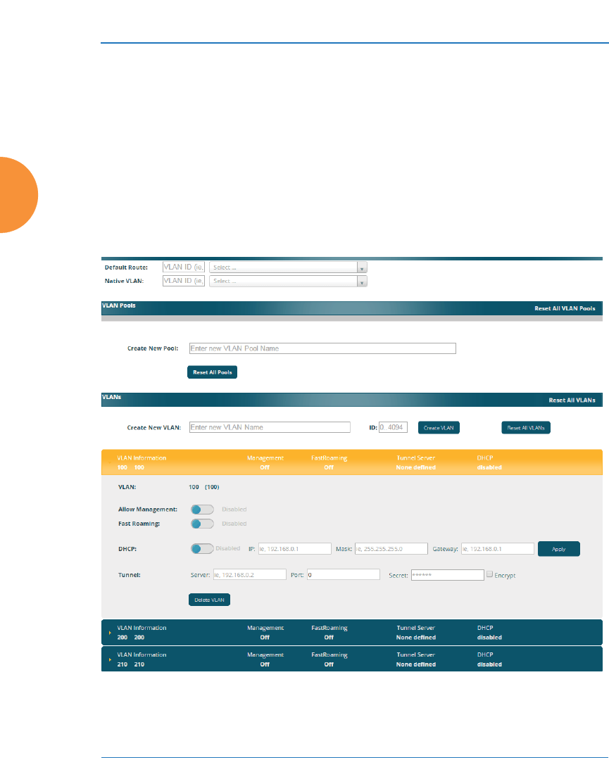
Wireless Access Point
216 Configuring the Wireless AP
VLAN pool. If a user has a VLAN assigned via a Group, then this VLAN will be
used rather than one from the VLAN pool.
To set up a VLAN pool, see the next section.
VLAN Management
This window allows you to set up VLANs and VLAN Pools. After creating a new
VLAN (added to the list of VLANs), you can modify the configuration
parameters of an existing VLAN or delete a selected VLAN. For ArrayOS 6.6 and
later releases, you may create up to 64 VLANs (up to 32 on XR-520).
Figure 126. VLAN Management

Wireless Access Point
Configuring the Wireless AP 217
Procedure for Managing VLANs
1. Default Route: This option sets a default route from the AP. The AP
supports a default route on native and tagged interfaces. Once the default
route is configured the AP will attempt to use Address Resolution
Protocol (ARP) to find the default router. ARP finds the MAC address of a
device with a given IP address by sending out a broadcast message
requesting this information. This option allows you to choose a default
VLAN route from the pull-down list. The IP Gateway must be established
for this function to work. After changing the Default Route, you must
click the Save button and then reboot.
2. Native VLAN: This option sets whether the AP management is tagged or
untagged. If you select a Native VLAN, then that VLAN will use an
untagged (Native) link. Otherwise, the AP will use 802.1Q tagging and a
specific VLAN ID with management enabled for management of the AP.
VLAN Pools
3. See “VLAN Pools” on page 215 for a discussion of VLAN pools. To add a
new pool, type its name in Create New Pool, and click ENTER. The new
VLAN pool entry is added to the list.
#The Wireless AP supports dynamic VLAN assignments specified by
RADIUS policy settings. When RADIUS sends these assignments, the
AP dynamically assigns wireless stations to VLANs as requested.
VLAN tags on traffic are passed through the AP (i.e., VLAN tags are not
stripped). Once a station has been dynamically moved to a new VLAN, it
will be shown in the Stations window as a member of the new VLAN.
(Figure 70 on page 127)
It is critical to configure all VLANs to be used on the AP, even those that
will be dynamically assigned.

Wireless Access Point
218 Configuring the Wireless AP
4. First, create all of the VLANs that will belong to this pool. See Step 5
below.
Click in the field for the new pool to display a list of VLANs. Add the
desired VLANs to this pool, one at a time. This field also provides a
search feature—type in a string, and a list will display all VLANs whose
names contain that string in any position (VLAN names are searched, but
not VLAN numbers). Click the Apply button on the right when done
adding VLANs. Note that the same VLAN can be added to more than one
pool. Be sure to consider any network implications of using the same
VLAN in multiple pools.
Click Reset if you want to remove all of the VLANs from this pool, i.e., to
empty it. Click Remove to delete this pool. You may use Reset All Pools
on the bottom to delete all pools.
VLANs
5. Create New VLAN: Enter a name for the new VLAN in this field.
ID: Enter a number for this VLAN (0-4094). Click the Create VLAN
button. The new VLAN appears in the list. Entries are sorted
alphabetically by VLAN name. Select the new entry to modify any of the
settings below.
6. Management: Move the slider if you want to allow AP management over
this VLAN.
7. Fast Roaming: Move the slider if you want to allow roaming over this
VLAN.
8. DHCP: Move the slider if you want the DHCP server to assign the IP
address, subnet mask and gateway address for this VLAN automatically,
otherwise you must go to the next step and assign these parameters
manually.
9. IP Address: If the DHCP option is disabled, enter a valid IP address for
this VLAN association.
10. Subnet Mask: If the DHCP option is disabled, enter the subnet mask IP
address for this VLAN association.

Wireless Access Point
Configuring the Wireless AP 219
11. Gateway: If the DHCP option is disabled, enter the IP gateway address
for this VLAN association.
12. Tunnel Server: If this VLAN is to be tunneled, enter the IP address or
host name of the tunnel server that will perform the tunneling. For more
information on virtual tunnels, please see “Understanding Virtual
Tunnels” on page 214.
13. Tunnel Server Port: If this VLAN is to be tunneled, enter the port number
of the tunnel server.
14. New Secret: Enter the password expected by the tunnel server.
15. Delete VLAN: To delete the selected VLAN, simply click the Delete
button to remove the VLAN from the list.
16. Click the Save button if you wish to make your changes permanent.
See Also
VLAN Statistics
VLANs
Tunnels
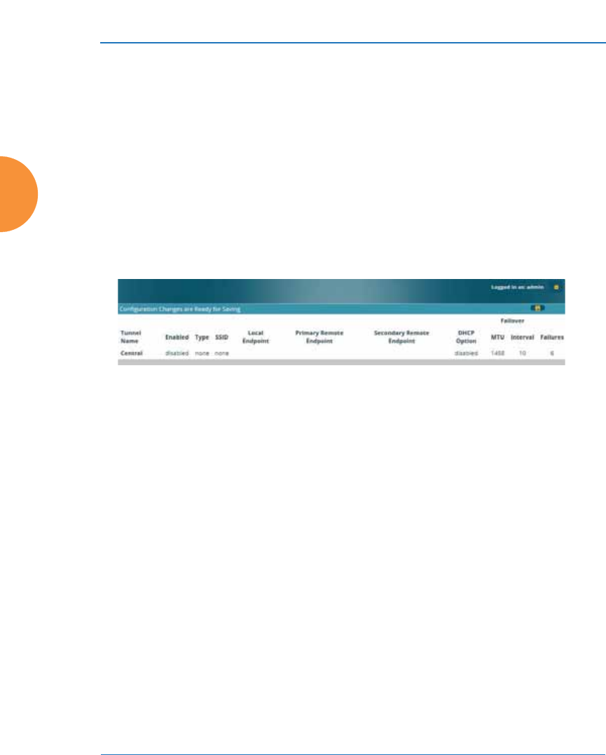
Wireless Access Point
220 Configuring the Wireless AP
Tunnels
This read-only window allows you to review the tunnels that have been defined
on the AP. It lists all tunnels and their settings, including the type of
authentication and the local and remote endpoints for each tunnel.
Tunnels are discussed in these sections:
z
About Xirrus Tunnels
z
Tunnel Management
z
SSID Assignments
z
VLAN Assignments
Figure 127. Tunnel Summary
About Xirrus Tunnels
Xirrus APs offer GRE (Generic Routing Encapsulation) tunneling with VLAN
support. This allows an AP to use tunnels to bridge Layer 2 traffic for one or more
SSIDs onto a single destination network through the Layer 3 network. You may
specify particular VLANs on an SSID to be tunneled, or tunnel all of the VLANs
that are on this SSID. GRE tunneling is quite flexible, and can encapsulate many
network layer protocols. As a result, it can support a variety of applications. For
example, a Wi-Fi hotspot can allow guest logins and use the tunnel to give guests
direct access to the Internet, without allowing access to the local network. In a
small office, you may define a tunnel to connect users to the corporate office
network. Tunnels may also used when providing cellular offload capability. For
non-GRE tunnels associated with particular VLANs, see “Understanding Virtual
Tunnels” on page 214.
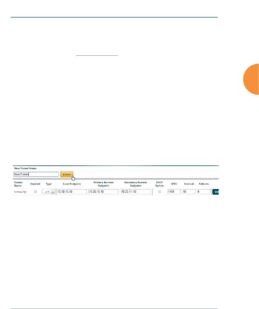
Wireless Access Point
Configuring the Wireless AP 221
Tunnels may be implemented with:
z
The Xirrus Tunnel Server (XTS)—see the Xirrus Tunnel Server User’s Guide.
For an additional discussion, see the Xirrus Tunnel Solutions Application
Note in the Xirrus Resource Center.
z
VTS —see “Virtual Tunnel Server (VTS)” on page 214.
To create a tunnel, you specify the Local Endpoint, which should be one of the
AP’s wired ports, and the Primary Remote Endpoint. A Secondary Remote
Endpoint may also be specified in case of a failure at the first endpoint. Traffic for
the designated VLANs on an SSID is sent in GRE encapsulated packets across the
Layer 3 network from the AP to the remote endpoint. When packets arrive, the
encapsulation is stripped and the resultant packets are passed to your switch with
802.1q VLAN tags for final Layer 2 processing. The process occurs in reverse for
packets traveling in the other direction.
Tunnel Management
This window allows you to create tunnels.
Figure 128. Tunnel Management
Procedure for Managing Tunnels
1. New Tunnel Name: Enter a name for the new tunnel in this field, then
click on the Create button. The new tunnel is added to the list. You may
crate up to 250 Layer 3 tunnels.
2. Enabled: The new tunnel is created in the disabled state. Click this
checkbox to enable it.
3. Type: Enter the type of tunnel, none or gre.

Wireless Access Point
222 Configuring the Wireless AP
4. Local Endpoint: Enter the IP address of the AP Gigabit or 10 Gigabit port
where the tunnel is to begin.
5. Primary Remote Endpoint: Enter the IP address of the remote endpoint
of the tunnel.
6. Secondary Remote Endpoint: This provides a failover capability. If the
primary tunnel fails, traffic is switched over to the secondary tunnel.
Enter the IP address of the remote endpoint of the secondary tunnel.
7. DHCP Option: When this option is enabled, the AP snoops station
DHCP requests and inserts relay agent information (Option 82, in the
CIRCUIT-ID sub-option) into these DHCP packets. Information inserted
includes AP BSSID, SSID name, and SSID encryption type. You may use
this option here or on the SSID Management page, but not in both places.
Information is inserted as a colon-separated text string in the CIRCUIT ID
value field in this format: [AP_MAC];[SSID];[ENC]
[AP_MAC] length = 17 (aa:bb:cc:dd:ee:ff)
[SSID] length = length of SSID name
[ENC] length = 1 (encryption type: 'o' = open, 's' = non-open)
Note that this is a different format than is used for Option 82 with SSIDs.
8. MTU: Set maximum transmission unit (MTU) size.
9. Interval: The tunnel mechanism will ping the current remote endpoint
periodically to ensure that it is still reachable. Enter the ping interval (in
seconds).
10. Failures: Enter the number of consecutive ping failures that will cause the
AP to consider the tunnel to be down. tunnel to failover to the other
remote endpoint.
11. Click the Save button if you wish to make your changes permanent.
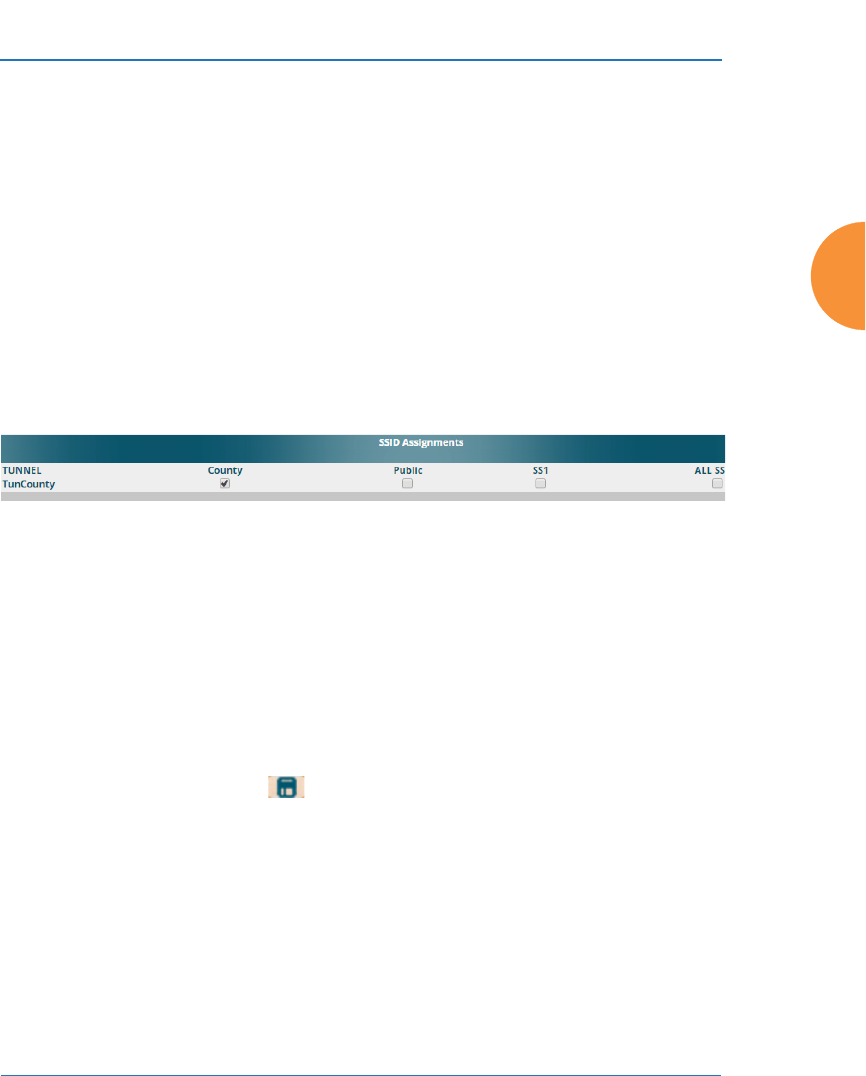
Wireless Access Point
Configuring the Wireless AP 223
12. Proceed to SSID Assignments to define the SSIDs for which each tunnel
will bridge data. You may create up to 16 tunnels. Assign one or more
SSIDs to each tunnel. You may restrict the tunnel to handling traffic for
particular VLANs on each SSID if you wish, as described in VLAN
Assignments.
SSID Assignments
This window allows you to select the SSIDs to be bridged by each tunnel. Station
traffic for SSIDs assigned will be bridged through the tunnel, but you may restrict
which VLANs are tunneled for each SSID (see VLAN Assignments, below). By
default, all VLANs will be tunneled. When VLAN traffic is tunneled, it will be
tagged accordingly.
Figure 129. Tunnel SSID Assignments
Procedure for Assigning SSIDs
This window lists the tunnels and SSIDs that you have defined.
1. For each tunnel, select the SSIDs that are to be bridged to the remote
endpoint. Clear the checkbox for any SSID that you no longer wish to
include in the tunnel. You may use the ALL SSIDs checkbox to toggle
between selecting all SSIDs, or none.
2. Click the Save button to make your changes permanent.
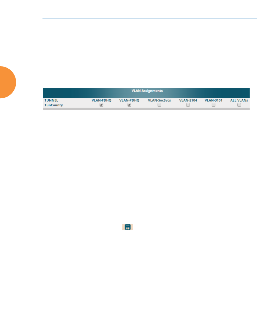
Wireless Access Point
224 Configuring the Wireless AP
VLAN Assignments
When you assign an SSID to a tunnel, all VLANs on that SSID will be transported
to the tunnel by default. This window allows you to select specific VLANs to be
bridged by each tunnel. A VLAN’s station traffic bridged through a tunnel will be
tagged accordingly. Station traffic for a VLAN that is not tunneled is forwarded to
the local subnet, i.e., dropped off locally at the edge of the switch network to
which the AP is connected.
Figure 130. Tunnel VLAN Assignments
Procedure for Assigning SSIDs
This window lists the tunnels and VLANs that you have defined.
1. For each tunnel, select the VLANs that are to be bridged to the remote
endpoint. Clear the checkbox for any VLAN that you no longer wish to
include in the tunnel. You may use the ALL VLANs checkbox to toggle
between selecting all VLANs, or none. Note that if you add any VLANs
to this list, then they will be the only VLANs transported on this tunnel.
Also note that many VLANs may be in use on an SSID if they are
assigned to stations dynamically by a RADIUS server or by user groups
(see “Groups” on page 304).
2. Click the Save button to make your changes permanent.
See Also
Tunnels
VLANs
SSIDs
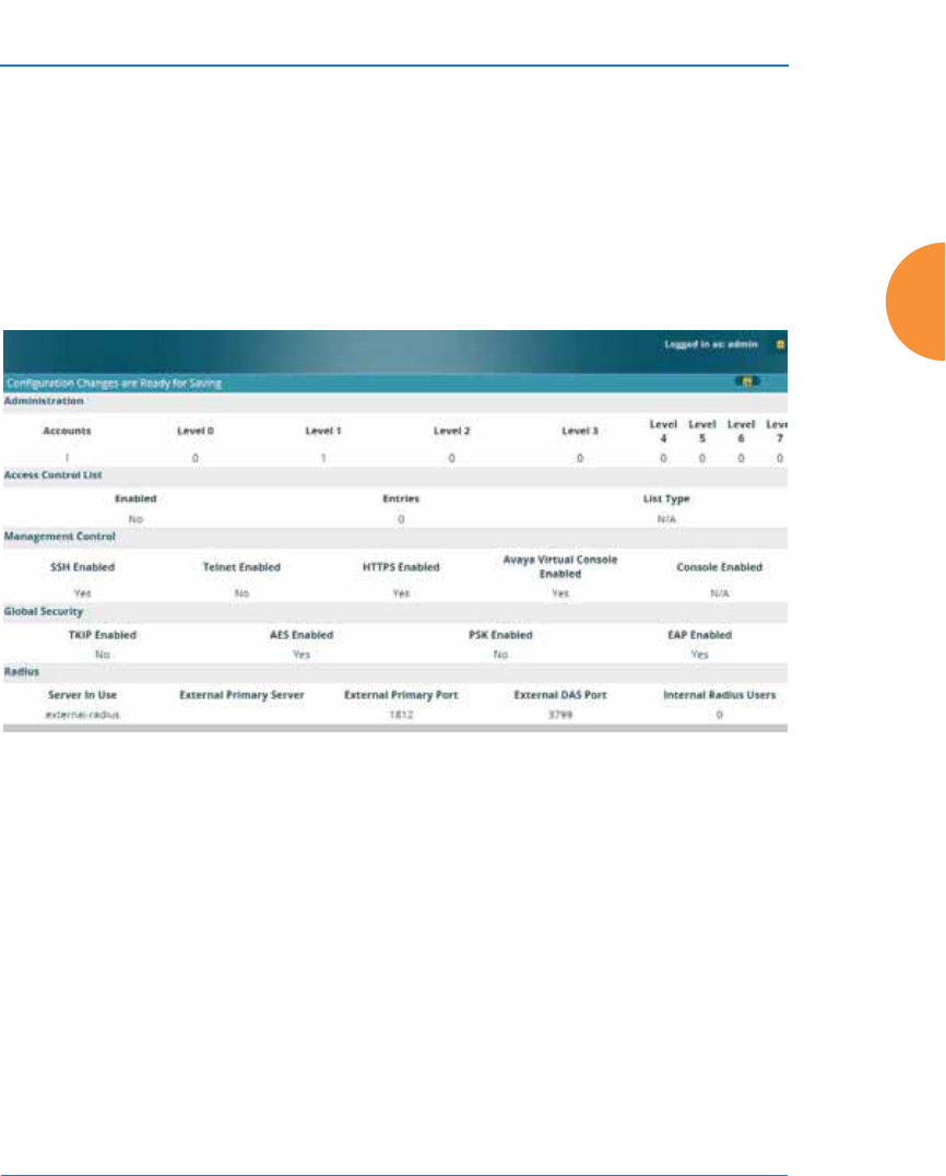
Wireless Access Point
Configuring the Wireless AP 225
Security
This status-only window allows you to review the AP’s security parameters. It
includes the assigned network administration accounts, Access Control List
(ACL) values, management settings, encryption and authentication protocol
settings, and RADIUS configuration settings. There are no configuration options
available in this window, but if you are experiencing issues with security, you
may want to print this window for your records.
Figure 131. Security
For additional information about wireless network security, refer to:
z
“Security Planning” on page 56
z
“Understanding Security” on page 226
z
The Security section of “Frequently Asked Questions” on page 522
For information about secure use of the WMI, refer to:
z
“Certificates and Connecting Securely to the WMI” on page 229
z
“Using the AP’s Default Certificate” on page 230
z
“Using an External Certificate Authority” on page 231
z
“About Creating Admin Accounts on the RADIUS Server” on page 235

Wireless Access Point
226 Configuring the Wireless AP
z
“About Creating User Accounts on the RADIUS Server” on page 255
Security settings are configured with the following windows:
z
“Admin Management” on page 231
z
“Admin Privileges” on page 233
z
“Admin RADIUS” on page 235
z
“Management Control” on page 238
z
“Access Control List” on page 248
z
“Global Settings” on page 250
z
“External Radius” on page 254
z
“Internal Radius” on page 258
z
“Active Directory” on page 260
z
“Rogue Control List” on page 264
z
“OAuth 2.0 Management” on page 265
Understanding Security
The Xirrus Wireless AP incorporates many configurable security features. After
initially installing an AP, always change the default administrator password (the
default is admin), and choose a strong replacement password (containing letters,
numbers and special characters). When appropriate, issue read-only
administrator accounts.
Other security considerations include:
z
SSH versus Telnet: Be aware that Telnet is not secure over network
connections and should be used only with a direct serial port connection.
When connecting to the unit’s Command Line Interface (CLI) over a
network connection, you must use a Secure SHell version 2 (SSH-2)
utility. SSH-2 provides stronger security than SSH-1. The most commonly
used freeware providing SSH tools is PuTTY.
z
Configuration auditing: The optional XMS offers powerful management
features for small or large wireless deployments, and can audit your
configuration settings automatically. In addition, using the XMS
eliminates the need for an FTP server.

Wireless Access Point
Configuring the Wireless AP 227
z
Choosing an encryption method: Wireless data encryption prevents
eavesdropping on data being transmitted or received over the airwaves.
The AP allows you to establish the following data encryption
configuration options:
•Open — this option offers no data encryption and is not
recommended, though you might choose this option if clients are
required to use a VPN connection through a secure SSH utility,
like PuTTy.
•Wired Equivalent Privacy (WEP) — this option provides minimal
protection (though much better than using an open network). An
early standard for wireless data encryption and supported by all
Wi-Fi certified equipment, WEP is vulnerable to hacking and is
therefore not recommended for use by Enterprise networks.
•Wi-Fi Protected Access (WPA and WPA2) — these are much
stronger encryption modes than WEP, using Temporal Key
Integrity Protocol (TKIP) or Advanced Encryption Standard
(AES) to encrypt data.
WPA solves security issues with WEP. It also allows you to
establish encryption keys on a per-user-basis, with key rotation
for added security. In addition, TKIP provides Message Integrity
Check (MIC) functionality and prevents active attacks on the
wireless network.
AES is the strongest encryption standard and is used by
government agencies; however, old legacy hardware may not be
capable of supporting the AES mode (it probably won’t work on
older wireless clients). Because AES is the strongest encryption
standard currently available, WPA2 with AES is highly
recommended for Enterprise networks.
Any of the above encryption methods can be used and an AP can support
multiple encryption methods simultaneously, but only one method may
be selected per SSID (except that selecting WPA-Both allows WPA and
WPA2 to be used at the same time on the same SSID). Otherwise, if
multiple security methods are needed, you must define multiple SSIDs.

Wireless Access Point
228 Configuring the Wireless AP
The encryption mode (WEP, WPA, etc.) is selected in the SSIDs >SSID
Management window (see “SSID Management” on page 277).
The encryption standard used with WPA or WPA2 (AES or TKIP) is
selected in the Security>Global Settings window under WPA Settings
(see “Global Settings” on page 250).
z
Choosing an authentication method: User authentication ensures that
users are who they say they are. For this purpose, the AP allows you to
choose between the following user authentication methods:
•Pre-Shared Key — users must manually enter a key (passphrase)
on the client side of the wireless network that matches the key
stored by the administrator in the AP.
This method should be used only for smaller networks when a
RADIUS server is unavailable. If PSK must be used, choose a
strong passphrase containing between 8 and 63 characters (20 is
preferred). Always use a combination of letters, numbers and
special characters. Never use English words separated by spaces.
•RADIUS 802.1x with EAP — 802.1x uses a RADIUS server to
authenticate large numbers of clients, and can handle different
Extensible Authentication Protocol (EAP) authentication
methods, including EAP-TLS, EAP-TTLS, EAP-PEAP, and LEAP-
Passthrough. The RADIUS server can be internal (provided by
the Wireless AP) or external. An external RADIUS server offers
more functionality and security, and is recommended for large
deployments. When using this method, user names and
passwords must be entered into the RADIUS server for user
authentication.
•MAC Address Access Control Lists (ACLs) — MAC address
ACLs provide a list of client adapter MAC addresses that are
allowed or denied access to the wireless network. Access Control
Lists work well when there are a limited number of users — in
this case, enter the MAC address of each user in the Allow list. In
the event of a lost or stolen MAC adapter, enter the affected MAC

Wireless Access Point
Configuring the Wireless AP 229
address in the Deny list. The Wireless AP will accept up to 1,000
ACL entries.
z
PCI DSS or FIPS 140-2 Security — to implement the requirements of
these security standards on the AP, please see “Auditing PCI DSS” on
page 585 or “Implementing FIPS Security” on page 591.
Certificates and Connecting Securely to the WMI
When you point your browser to the AP to connect to the WMI, the AP presents
an X.509 security certificate to the browser to establish a secure channel. One
significant piece of information in the certificate is the AP’s host name. This ties
the certificate to a particular AP and ensures the client that it is connecting to that
host.
Certificate Authorities (CAs) are entities that digitally sign certificates, using their
own certificates (for example, VeriSign is a well-known CA). When the AP
presents its certificate to the client’s browser, the browser looks up the CA that
signed the certificate to decide whether to trust it. Browsers ship with a small set
of trusted CAs already installed. If the browser trusts the certificate’s CA, it
checks to ensure the host name (and IP address) match those on the certificate. If
any of these checks fail, you get a security warning when connecting to the WMI.
The AP ships with a default certificate that is signed by the Xirrus CA. You may
choose to use this certificate, or to use a certificate issued by the CA of your
choice, as described in the following sections:
z
Using the AP’s Default Certificate
z
Using an External Certificate Authority
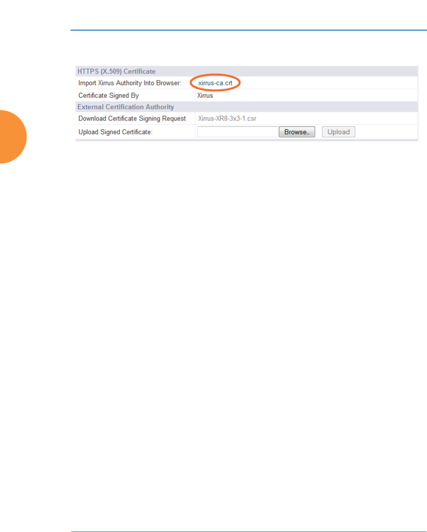
Wireless Access Point
230 Configuring the Wireless AP
Using the AP’s Default Certificate
Figure 132. Import Xirrus Certificate Authority
The AP’s certificate is signed by a Xirrus CA that is customized for your AP and
its current host name. By default, browsers will not trust the AP’s certificate. You
may import the Xirrus certificate to instruct the browser to trust the Xirrus CA on
all future connections to APs. The certificate for the Xirrus CA is available on the
AP, so that you can import it into your browser’s cache of trusted CAs (right
alongside VeriSign, for example). On the Management Control window of the
WMI you will see the xirrus-ca.crt file. (Figure 132)
By clicking and opening this file, you can follow your browser’s instructions and
import the Xirrus CA into your CA cache (see “HTTPS (X.509) Certificate” on
page 245 for more information). This instructs your browser to trust any of the
certificates signed by the Xirrus CA, so that when you connect to any of our APs
you should no longer see the warning about an untrusted site. Note however, that
this only works if you use the host name when connecting to the AP. If you use
the IP address to connect, you get a lesser warning saying that the certificate was
only meant for ‘hostname’.
Since an AP’s certificate is based on the AP’s host name, any time you change the
host name the AP’s CA will regenerate and sign a new certificate. This happens
automatically the next time you reboot after changing the host name. If you have
already installed the Xirrus CA on a browser, this new AP certificate should
automatically be trusted.
When you install the Xirrus CA in your browser, it will trust a certificate signed
by any Xirrus AP, as long as you connect using the AP’s host name.
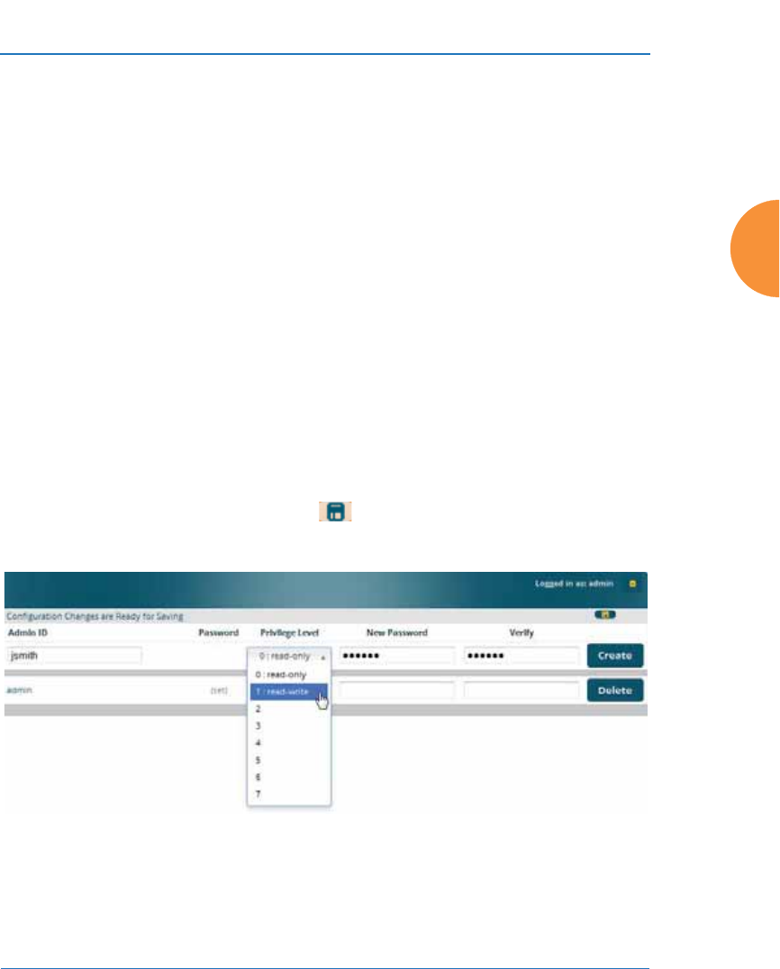
Wireless Access Point
Configuring the Wireless AP 231
Using an External Certificate Authority
If you prefer, you may install a certificate on your AP signed by an outside CA.
The AP’s certificate is used for security when stations attempt to associate to an
SSID that has Web Page Redirect (captive portal) enabled. In this case, it is
preferable for the AP to present a certificate from an external CA that is likely to
be trusted by most browsers. When a WPR login page is presented, the user will
not see a security error if the AP’s certificate was obtained from an external CA
that is already trusted by the user’s browser.
WMI provides options for creating a Certificate Signing Request that you can
send to an external CA, and for uploading the signed certificate to the AP after
you obtain it from the CA. This certificate will be tied to the AP’s host name and
private key. See “External Certificate Authority” on page 246 for more details.
Admin Management
This window allows you to manage network administrator accounts (create,
modify and delete). It also allows you to limit account access to a read only status.
When finished, click the Save button if you wish to make your changes
permanent.
Figure 133. Admin Management

Wireless Access Point
232 Configuring the Wireless AP
Procedure for Creating or Modifying Network Administrator Accounts
1. Admin ID: Enter the login name for a new network administrator ID.
The length of the ID must be between 5 and 50 characters, inclusive.
2. Read/Write: Choose 1:read-write if you want to give this administrator
ID full read/write privileges, or choose 0:read-only to restrict this user to
read only status. In the read only mode, administrators cannot save
changes to configurations. Or you may select one of your custom-defined
privilege levels (see “Admin Privileges” on page 233).
3. New Password: Enter a password for this ID. The length of the password
must be between 5 and 50 characters, inclusive.
4. Verify: Re-enter the password in this field to verify that you typed the
password correctly. If you do not re-enter the correct password, an error
message is displayed).
5. Click on the Create button to add this administrator ID to the list.
6. Click the Save button if you wish to make your changes permanent.
See Also
Admin Privileges
External Radius
Global Settings
Internal Radius
Management Control
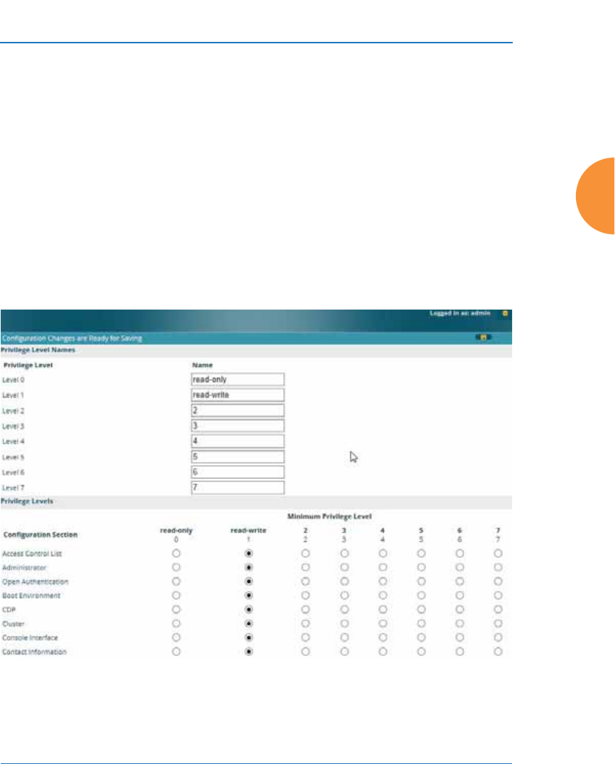
Wireless Access Point
Configuring the Wireless AP 233
Admin Privileges
This window provides a detailed level of control over the privileges of AP
administrators. Administrators may be assigned one of eight Privilege Levels.
You may define the privilege level of each major feature (Configuration Section)
that may be configured on the AP. For example, say that you set the privilege
level to 4 for Reboot AP, Security, Radius Server, and SNMP, and you leave all
other configuration sections at the default privilege level of 1. In this case, any
administrator with a privilege level of 4 or higher may perform any operation on
the AP, while an administrator with a privilege level lower than 4 but at least 1
may perform any operation except those whose level was set to 4. An error
message will be displayed if an operation is attempted without a sufficient
privilege level.
Figure 134. Admin Privileges

Wireless Access Point
234 Configuring the Wireless AP
Privilege level 0 is read-only. As a minimum, all administrators have permission
for read access to all areas of AP configuration. Higher privilege levels may be
used to define additional privileges for specific configuration sections.
If you are using an Admin RADIUS server to define administrator accounts,
please see “RADIUS Vendor Specific Attribute (VSA) for Xirrus” on page 532 to
set the privilege level for each administrator.
Procedure for Configuring Admin Privileges
1. Privilege Level Names (optional): You may assign a Name to each
Privilege Level. The name may be used to describe the access granted by
this level. By default, levels 0 and 1 are named read-only and read-write,
respectively, and levels 2 through 7 have the same name as their level
number.
2. Privilege Levels: Use this section to assign a Minimum Privilege Level
to selected Configuration Sections as desired. By default, all sections are
assigned level 1. When you select a higher privilege level for a
configuration section, then only administrators who have at least that
privilege level will be able to make configuration changes to that section.
3. You may click ^ at the bottom of any row to toggle the values in the entire
column to either on or off.
4. Click the Save button if you wish to make your changes permanent.
See Also
External Radius
Groups
Admin Management
Admin RADIUS
Security

Wireless Access Point
Configuring the Wireless AP 235
Admin RADIUS
This window allows you to set up authentication of network administrators via
RADIUS. Using RADIUS to control administrator accounts for logging in to APs
has these benefits:
z
Centralized control of administrator accounts.
z
Less effort — you don't have to set up user names and passwords on each
AP; just enter them once on the RADIUS server and then all of the APs
can pull from the RADIUS server.
z
Enforced policies — you may set password rules (e.g., passwords must
contain at least one number and be at least 12 characters in length), and
you may set expiration times for passwords.
Admin RADIUS settings override any local administrator accounts configured on
the Admin Management window. If you have Admin RADIUS enabled, all
administrator authentication is done via the configured RADIUS servers. The
only exception to this is when you are connected via the Console port (using CLI).
If you are using the Console port, the AP will authenticate administrators using
accounts configured on the Admin Management window first, and then use the
RADIUS servers. This provides a safety net to be ensure that you are not
completely locked out of an AP if the RADIUS server is down.
About Creating Admin Accounts on the RADIUS Server
Permissions for RADIUS administrator accounts are controlled by the RADIUS
Xirrus-Admin-Role attribute. This is a Vendor Specific Attribute (VSA). To define
the privileges permitted to an administrator account, set the value of its Xirrus-
Admin-Role attribute to the desired Privilege Level Name string, as defined in
“Admin Privileges” on page 233. For more information about the RADIUS VSAs
used by Xirrus, see “RADIUS Vendor Specific Attribute (VSA) for Xirrus” on
page 532.
When configuring administrator accounts on the RADIUS server, you must
observe the same restrictions for length and legal characters as when creating
these accounts on the AP using the Admin Management window: the user name
and password must be between 5 and 50 characters, inclusive.
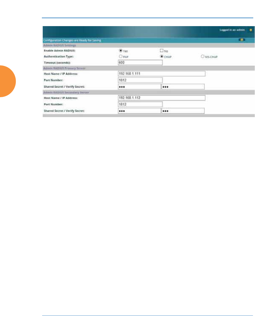
Wireless Access Point
236 Configuring the Wireless AP
Figure 135. Admin RADIUS
Procedure for Configuring Admin RADIUS
Use this window to enable/disable administrator authentication via RADIUS,
and to set up primary and secondary servers to use for authentication of
administrators attempting to log in to the AP.
1. Admin RADIUS Settings:
a. Enable Admin RADIUS: Click Yes to enable the use of RADIUS to
authenticate administrators logging in to the AP. You will need to
specify the RADIUS server(s) to be used.
b. Authentication Type: Select the protocol used for authentication of
administrators, CHAP or PAP (the default).
•Password Authentication Protocol (PAP), is a simple protocol.
PAP transmits ASCII passwords over the network “in the clear”
(unencrypted) and is therefore considered insecure.
•Challenge-Handshake Authentication Protocol (CHAP) is a more
secure protocol. The login request is sent using a one-way hash
function.

Wireless Access Point
Configuring the Wireless AP 237
c. Timeout (seconds): Define the maximum idle time (in seconds)
before the RADIUS server’s session times out. The default is 600
seconds.
2. Admin RADIUS Primary Server: This is the RADIUS server that you
intend to use as your primary server.
a. Host Name / IP Address: Enter the IP address or domain name of this
external RADIUS server.
b. Port Number: Enter the port number of this RADIUS server. The
default is 1812.
c. Shared Secret / Verify Secret: Enter the shared secret that this
RADIUS server will be using, then re-enter the shared secret to verify
that you typed it correctly.
3. Admin RADIUS Secondary Server (optional): If desired, enter an
alternative external RADIUS server. If the primary RADIUS server
becomes unreachable, the AP will “failover” to the secondary RADIUS
server (defined here).
a. Host Name / IP Address: Enter the IP address or domain name of this
RADIUS server.
b. Port Number: Enter the port number of this RADIUS server.
The default is 1812.
c. Shared Secret / Verify Secret: Enter the shared secret that this
RADIUS server will be using, then re-enter the shared secret to verify
that you typed it correctly.
#The shared secret that you define must match the secret used by the
RADIUS server.
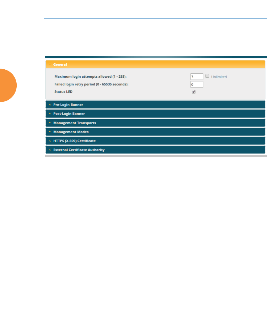
Wireless Access Point
238 Configuring the Wireless AP
Management Control
This window allows you to enable or disable the AP management interfaces and
set their inactivity time-outs. The range is 300 (default) to 100,000 seconds.
Figure 136. Management Control
Procedure for Configuring Management Control
1. Management Settings:
a. Maximum login attempts allowed (1-255): After this number of
consecutive failing administrator login attempts via ssh or telnet, the
Failed login retry period is enforced. The default is 3.
b. Failed login retry period (0-65535 seconds): After the maximum
number (defined above) of consecutive failing administrator login
attempts via ssh or telnet, the administrator’s IP address is denied
access to the AP for the specified period of time (in seconds). The
default is 0.
c. Pre-login Banner: Text that you enter here will be displayed below
the WMI login prompt. (Figure 137) Click the Submit button when
done typing.
If you wish to display more than 256 characters of text (for instance,
to display usage restrictions for the wireless network), you may
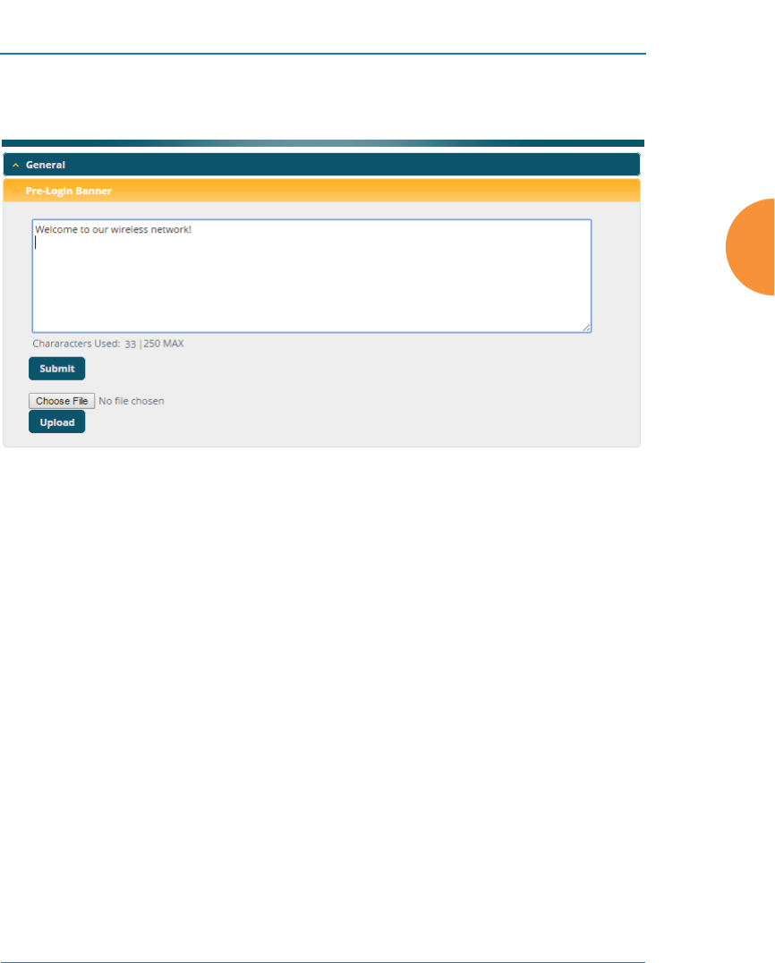
Wireless Access Point
Configuring the Wireless AP 239
upload a text file. Click Choose File and browse to the file. Click
Upload when done.
Figure 137. Pre-login Banner
d. Post-login Banner: Text that you enter here will be displayed in a
message box after a user logs in to the WMI.
If you wish to display more than 256 characters of text, upload a text
file. Click Choose File and browse to the file, then click Upload.
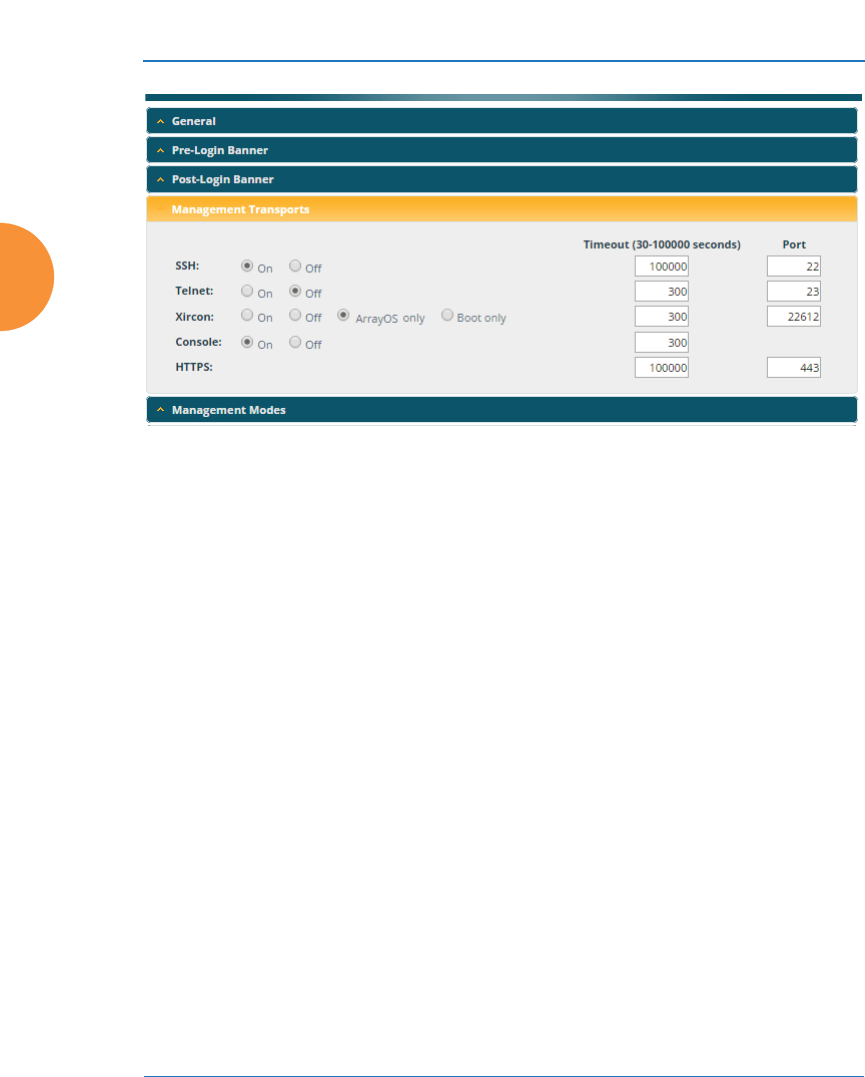
Wireless Access Point
240 Configuring the Wireless AP
Figure 138. Management Transports
2. SSH
a. On/Off: Choose On to enable management of the AP over a Secure
Shell (SSH-2) connection, or Off to disable this feature. Be aware that
only SSH-2 connections are supported by the AP. SSH clients used for
connecting to the AP must be configured to use SSH-2.
b. Connection Timeout 30-100000 (Seconds): Enter a value in this field
to define the timeout (in seconds) before your SSH connection is
disconnected. The value you enter here must be between 30 seconds
and 100,000 seconds.
c. Port: Enter a value in this field to define the port used by SSH.
The default port is 22.
3. Telnet:
a. On/Off: Choose On to enable AP management over a Telnet
connection, or Off to disable this feature. SSH offers a more secure
connection than Telnet, and is recommended over Telnet.
b. Connection Timeout 30-100000 (Seconds): Enter a value in this field
to define the timeout (in seconds) before your Telnet connection is

Wireless Access Point
Configuring the Wireless AP 241
disconnected. The value you enter here must be between 30 seconds
and 100,000 seconds.
c. Port: Enter a value in this field to define the port used by Telnet.
The default port is 23.
4. Xircon
The Xircon utility connects to Xirrus APs that do not have a physical
console port, or whose console port is not accessible. Please see
“Securing Low Level Access to the AP” on page 81 for more information
about Xircon. You can enable or disable Xircon access to the AP as
instructed below.
a. On/Off: Choose On to enable Xircon access to the AP at the ArrayOS
(CLI) and Xirrus Boot Loader (XBL) levels, or Off to disable access at
both levels. Xircon access is On by default.
b. ArrayOS only: Choose this radio button to enable Xircon access at the
ArrayOS level only (i.e., Xircon can access CLI only). Access to the AP
at the Xirrus Boot Loader (XBL) level is disabled.
c. Boot only: Choose this radio button to enable Xircon access at the
Xirrus Boot Loader (XBL) level only. ArrayOS level (CLI) access to the
AP is disabled.
d. Connection Timeout 30-100000 (Seconds): Enter a value in this field
to define the timeout (in seconds) before your Xircon connection is
disconnected. The value you enter here must be between 30 seconds
and 100,000 seconds.
e. Port: Enter a value in this field to define the port used by Xircon.
The default port is 22612.
!Warning: If you disable Xircon access completely on models that have no
console port, you must ensure that you do not lose track of the username and
password to log in to CLI/WMI! There is no way to recover from a lost
password, other than returning the AP to Xirrus.
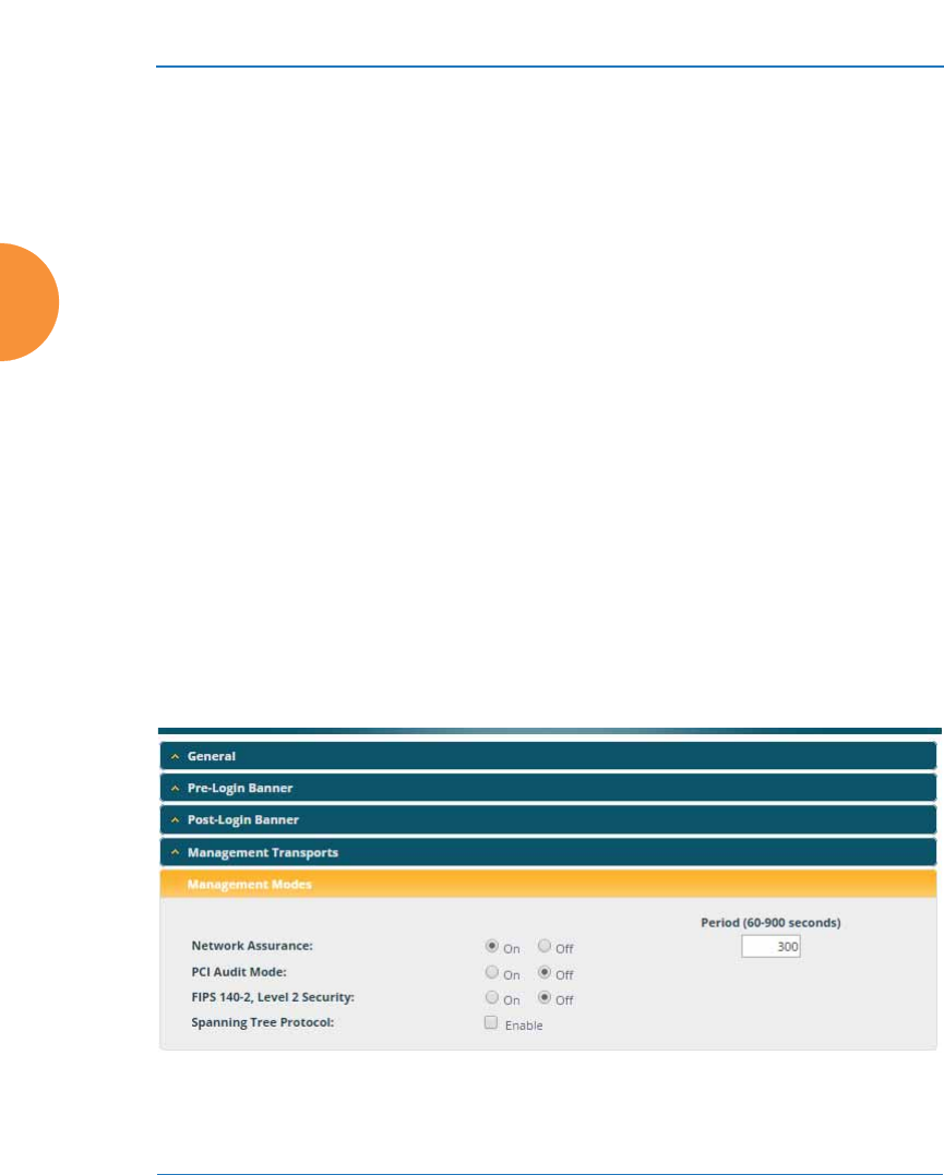
Wireless Access Point
242 Configuring the Wireless AP
5. Console
a. On/Off: Choose On to enable management of the AP via a serial
connection, or choose Off to disable this feature.
b. Connection Timeout 30-100000 (Seconds): Enter a value in this field
to define the timeout (in seconds) before your serial connection is
disconnected. The value you enter here must be between 30 seconds
and 100,000 seconds.
6. HTTPS
a. Connection Timeout 30-100000 (Seconds): Enter a value in this field
to define the timeout (in seconds) before your HTTPS connection is
disconnected. The value you enter here must be between 30 seconds
and 100,000 seconds. Management via HTTPS (i.e., the Web
Management Interface) cannot be disabled on this window. To
disable management over HTTPS, you must use the Command Line
Interface.
b. Port: Enter a value in this field to define the port used by SSH.
The default port is 443.
7. Management Modes
Figure 139. Management Modes

Wireless Access Point
Configuring the Wireless AP 243
a. Network Assurance: Click the On button to enable this mode.
Network assurance checks network connectivity to each server that
you configure, such as the NTP server, RADIUS servers, SNMP trap
hosts, etc. By proactively identifying network resources that are
unavailable, the network manager can be alerted of problems
potentially before end-users notice an issue. The distributed
intelligence of APs provides this monitoring at multiple points across
the network, adding to the ability to isolate the problem and expedite
the resolution
Connectivity is checked when you configure a server. If a newly
configured server is unreachable, you will be notified directly and a
Syslog entry is created. Configured servers are checked once per
Period which by default is 300 seconds (five minutes). Servers are
checked regardless of whether they are configured as IP addresses or
host names.
If a server becomes unreachable, a Syslog message is generated.
When the server again becomes reachable, another Syslog message is
generated.
To view the status of all configured servers checked by this feature,
please see “Network Assurance” on page 113.
b. PCI Audit Mode: Click the On button to enable this mode, which is
provided as an aid to setting up APs to pass PCI DSS audit
requirements. In PCI Audit Mode, the AP checks whether its
configuration is appropriate for auditing PCI DSS wireless security.
This mode does not change any other settings, but will inform you of
any incorrect settings that exist. Furthermore, the AP will monitor
changes that you make to its configuration in CLI or the WMI. PCI
Mode will warn you (and issue a Syslog message) if the change is
inappropriate for PCI DSS. A warning is issued when a non-
compliant change is first applied to the AP, and also if you attempt to
save a configuration that is non-compliant. Use this command in
conjunction with “The Xirrus AP PCI Compliance Configuration” on
page 587 to ensure that you are using the AP in accordance with the

Wireless Access Point
244 Configuring the Wireless AP
PCI DSS requirements. For more information, see “Auditing PCI
DSS” on page 585.
The pci-audit command checks items such as:
•Telnet is disabled.
•Admin RADIUS is enabled (admin login authentication is via
RADIUS server).
•An external Syslog server is in use.
•All SSIDs must set encryption to WPA or better (which also
enforces 802.1x authentication)
c. FIPS 140-2, Level 2 Security: Please see “Implementing FIPS
Security” on page 591 for more information, including step-by-step
instructions for proceeding to implement FIPS Level 2 Security
requirements on the AP.
Click the On button to enable FIPS. This will perform all of the setting
changes necessary to make the AP comply with FIPS requirements. A
message is displayed showing the changes that were performed. The
AP continues to enforce FIPS requirements by preventing you from
making non-compliant configuration changes. Click the Off button to
stop enforcing FIPS requirements.
Note that when you enable FIPS, the AP does not save your previous
settings, and it will not restore them if you click the Off button. If you
think you may wish to disable FIPS and restore your previous
configuration at some later time, use Set Restore Point to save a copy
of your configuration before enabling FIPS (see Step 4 on page 419 in
Using Tools on the Wireless AP).
d. Spanning Tree Protocol: this protocol is used in Layer 2 networks to
turn off ports when necessary to prevent network loops. It is Off by
default, and is turned on automatically if you are using WDS to
interconnect APs using wireless links. Use the On button to enable
spanning tree if your network topology requires it. See “Spanning
Tree Status” on page 109.
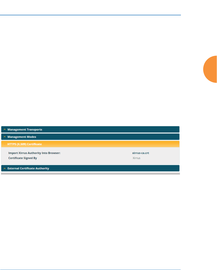
Wireless Access Point
Configuring the Wireless AP 245
8. HTTPS (X.509) Certificate
,
Figure 140. HTTPS (X.509) Certificate
a. Import Xirrus Authority into Browser: This feature imports the
Xirrus Certificate Authority (CA) into your browser (for a discussion,
please see “Certificates and Connecting Securely to the WMI” on
page 229). Click the link (xirrus-ca.crt), and then click Open to view
or install the current Xirrus CA certificate. Click Install Certificate to
start your browser’s Certificate Install Wizard. We recommend that
you use this process to install Xirrus as a root authority in your
browser.
When you assign a Host Name to your AP using the Express Setup
window, then the next time you reboot the AP (or restart the HTTPS
#ArrayOS releases 6.5 and above only support 2048-bit certificates, while
previous releases only support 1024-bit certificates. When ArrayOS is
upgraded to 6.5 or above, a new self-signed certificate will be automatically
generated.
If you have imported a previous (pre-Release 6.5 version) Xirrus CA-signed
certificate into your browser, the trusted Xirrus CA needs to be updated.
Delete the current Xirrus CA in the browser. Upgrade the AP to release 6.5
or above and then download the new xirrus-ca.crt file and import it into the
browser as a trusted CA, as explained below.
If you are using a certificate signed by an external CA, its use is not
impacted in any way by this change.
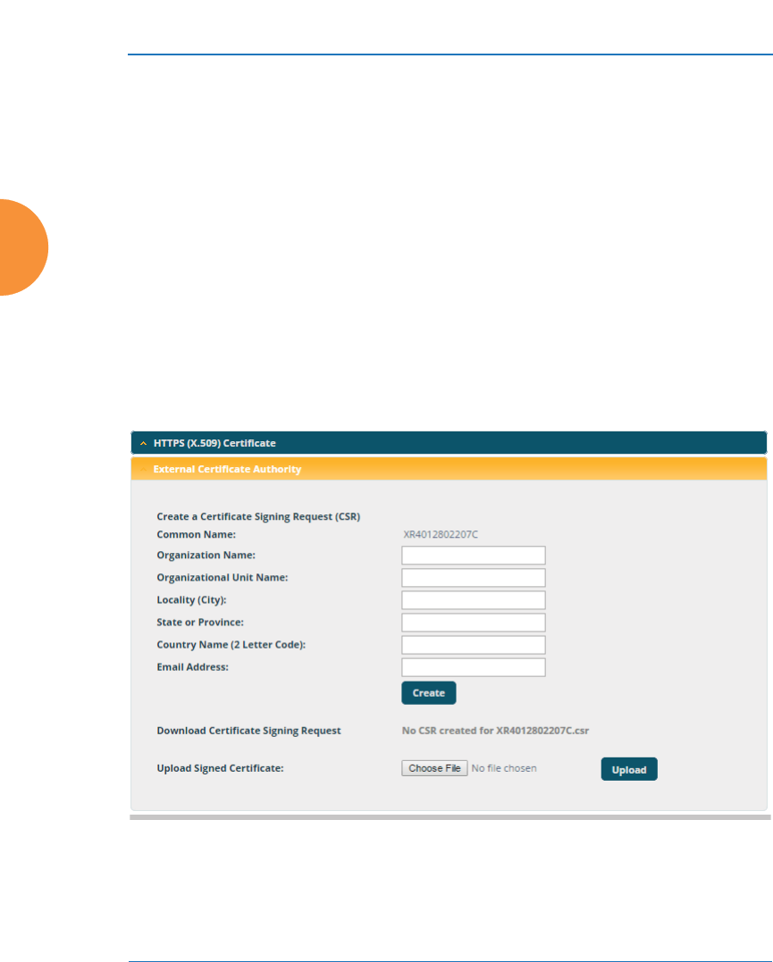
Wireless Access Point
246 Configuring the Wireless AP
service by turning it off and on again using the CLI), it automatically
creates a security certificate for that host name. That certificate uses
Xirrus as the signing authority. Thus, in order to avoid having
certificate errors on your browser when using WMI:
•You must have assigned a host name to the AP and rebooted at
some time after that.
•Use Import Xirrus Authority into Browser
•Access WMI by using the host name of the AP rather than its IP
address.
b. HTTPS (X.509) Certificate Signed By: This read-only field shows the
signing authority for the current certificate.
9. External Certificate Authority
Figure 141. External Certificate Authority

Wireless Access Point
Configuring the Wireless AP 247
This step and Step 10 allow you to obtain a certificate from an external
authority and install it on an AP. “Using an External Certificate
Authority” on page 231 discusses reasons for using an external CA.
For example, to obtain and install a certificate from VeriSign on the AP,
follow these steps:
•If you don’t already have the certificate from the external (non-
Xirrus) Certificate Authority, see Step 10 to create a request for a
certificate.
•Use option (a) to review the request and copy its text to send to
Ver iS ign.
•When you receive the new certificate from VeriSign, upload it to the
AP using option (b).
External Certification Authority has the following options:
a. Download Certificate Signing Request: After creating a certificate
signing request (.csr file — Step 10), click the View button to review it.
If it is satisfactory, click the name of the .csr file to display the text of
the request. You can then copy this text and use it as required by the
CA. You may also click on the filename of the .csr file to download it
to your local computer.
b. Upload Signed Certificate: To use a custom certificate signed by an
authority other than Xirrus, use the Browse button to locate the
certificate file, then click Upload to copy it to the AP. The AP’s web
server will be restarted and will pick up the new certificate. This will
terminate any current web sessions, and you will need to reconnect
and re-login to the AP.
10. To create a Certificate Signing Request
a. Fill in the fields in this section: Common Name, Organization Name,
Organizational Unit Name, Locality (City), State or Province,
Country Name, and Email Address. Spaces may be used in any of
the fields, except for Common Name, Country Name, or Email
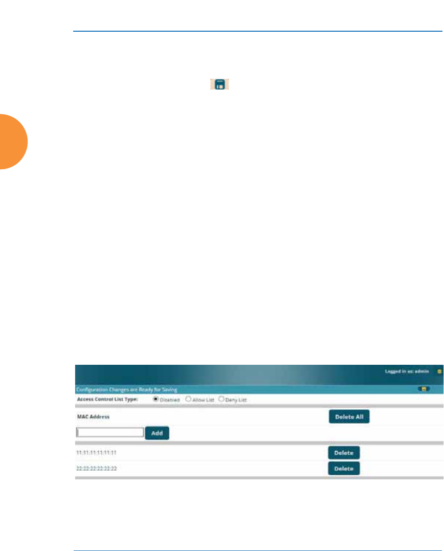
Wireless Access Point
248 Configuring the Wireless AP
Address. Click the Create button to create the certificate signing
request. See Step 9 above to use this request.
11. Click the Save button if you wish to make your changes permanent.
See Also
Interfaces - to enable/disable management over an Ethernet interface
Global Settings - to enable/disable management over IAPs
Admin Management
External Radius
Global Settings
Internal Radius
Access Control List
Security
Access Control List
This window allows you to enable or disable the use of the global Access Control
List (ACL), which controls whether a station with a particular MAC address may
associate to the AP. You may create station access control list entries and delete
existing entries, and control the type of list.
There is only one global ACL, and you may select whether its type is an Allow
List or a Deny List, or whether use of the list is disabled.
Figure 142. Access Control List

Wireless Access Point
Configuring the Wireless AP 249
There is also a per-SSID ACL (see “Per-SSID Access Control List” on page 299). If
the same MAC address is listed in both the global ACL and in an SSID’s ACL, and
if either ACL would deny that station access to that SSID, then access will be
denied.
Procedure for Configuring Access Control Lists
1. Access Control List Type: Select Disabled to disable use of the Access
Control List, or select the ACL type — either Allow List or Deny List.
•Allow List: Only allows the listed MAC addresses to associate to
the AP. All others are denied.
•Deny List: Denies the listed MAC addresses permission to
associate to the AP. All others are allowed.
2. MAC Address: If you want to add a MAC address to the ACL, enter the
new MAC address here, then click on the Add button. The MAC address
is added to the ACL. You may use a wildcard (*) for one or more digits to
match a range of addresses. You may create up to 1000 entries.
3. Delete: You can delete selected MAC addresses from this list by clicking
their Delete buttons.
4. Click the Save button if you wish to make your changes permanent.
See Also
External Radius
Global Settings
Internal Radius
Management Control
Security
Station Status Windows (list of stations that have been detected by the AP)
#In addition to these lists, other authentication methods (for
example, RADIUS) are still enforced for users.
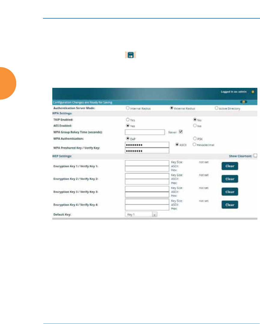
Wireless Access Point
250 Configuring the Wireless AP
Global Settings
This window allows you to establish the security parameters for your wireless
network, including WEP, WPA, WPA2 and RADIUS authentication. When
finished, click the Save button if you wish to make your changes permanent.
For additional information about wireless network security, refer to “Security
Planning” on page 56 and “Understanding Security” on page 226.
Figure 143. Global Settings (Security)
Procedure for Configuring Network Security
1. Authentication Server Mode: Choose the type of Authentication Server
that you will use for authenticating wireless users:
•Internal RADIUS defines wireless user accounts locally on the AP.
See “Internal Radius” on page 258.
•External RADIUS defines wireless user accounts on a RADIUS
server external to the AP. See “External Radius” on page 254.

Wireless Access Point
Configuring the Wireless AP 251
•Active Directory defines wireless user accounts on an Active
Directory server external to the AP. See “Active Directory” on
page 260.
WPA Settings
These settings are used if the WPA or WPA2 encryption type is selected on the
SSIDs >SSID Management window or the Express Setup window (on this
window, encryption type is set in the SSID Settings: Wireless Security field).
2. TKIP Enabled: Choose Yes to enable TKIP (Temporal Key Integrity
Protocol), or choose No to disable TKIP.
3. AES Enabled: Choose Yes to enable AES (Advanced Encryption
Standard), or choose No to disable AES. If both AES and TKIP are
enabled, the station determines which will be used.
4. WPA Group Rekey Time (seconds): Enter a value to specify the group
rekey time (in seconds). The default is Never.
5. WPA Preshared Key / Verify Key: If you enabled PSK, enter a passphrase
here, then re-enter the passphrase to verify that you typed it correctly.
#TKIP encryption does not support high throughput rates for 802.11n, per
the IEEE 802.11n specification.
TKIP should never be used for WDS links on APs.

Wireless Access Point
252 Configuring the Wireless AP
WEP Settings
These settings are used if the WEP encryption type is selected on the SSIDs >
SSID Management window or the Express Setup window (on this window,
encryption type is set in the SSID Settings: Wireless Security field).
Click the Show Cleartext button to make the text that you type in to the Key
fields visible.
6. Encryption Key 1 / Verify Key 1:
Key Size: Key length is automatically computed based on the Encryption
Key that you enter
•5 ASCII characters (10 hex) for 40 bits (WEP-64)
•13 ASCII characters for (26 hex) 104 bits (WEP-128)
Encryption Key 1 / Verify Key 1: Enter an encryption key in ASCII or
hexadecimal. The ASCII and translated hexadecimal values will appear
to the right if you selected the Show Cleartext button.
Re-enter the key to verify that you typed it correctly. You may include
special ASCII characters, except for the double quote symbol (“).
7. Encryption Key 2 to 4/ Verify Key 2 to 4/ Key Mode/Length (optional): If
desired, enter up to four encryption keys, in the same way that you
entered the first key.
8. Default Key: Choose which key you want to assign as the default key.
Make your selection from the pull-down list.
9. Click the Save button if you wish to make your changes permanent.
#WEP encryption does not support high throughput rates or features like
frame aggregation or block acknowledgments for 802.11n, per the IEEE
802.11n specification.
WEP should never be used for WDS links on APs.
#After configuring network security, the configuration must be
applied to an SSID for the new functionality to take effect.

Wireless Access Point
Configuring the Wireless AP 253
See Also
Admin Management
External Radius
Internal Radius
Access Control List
Management Control
Security
Security Planning
SSID Management
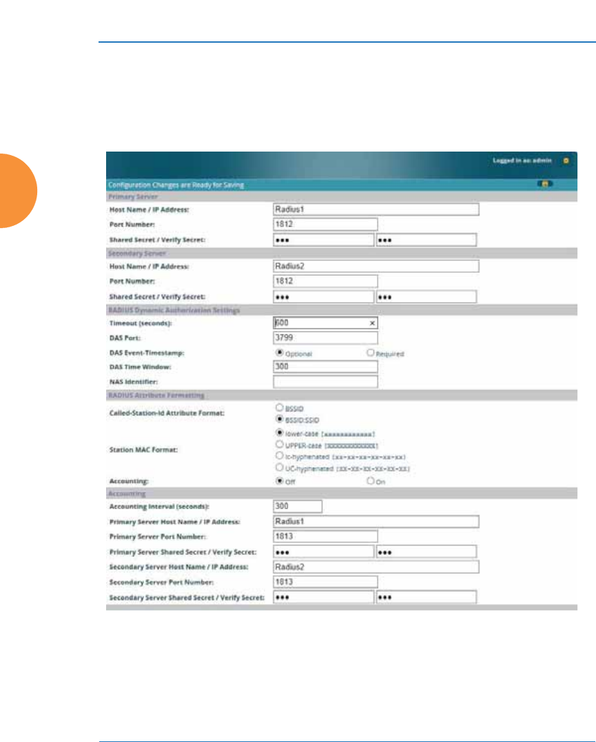
Wireless Access Point
254 Configuring the Wireless AP
External Radius
This window allows you to define the parameters of an external RADIUS server
for user authentication. To set up an external RADIUS server, you must choose
External Radius as the Authentication Server Mode in “Global Settings” on
page 250.
Figure 144. External RADIUS Server
If you want to include user group membership in the RADIUS account
information for users, see “Understanding Groups” on page 304. User groups
allow you to easily apply a uniform configuration to a user on the AP.

Wireless Access Point
Configuring the Wireless AP 255
About Creating User Accounts on the RADIUS Server
An attribute of user (wireless client) accounts is controlled by RADIUS Vendor
Specific Attributes (VSAs) defined by Xirrus. In particular, use the VSA named
Xirrus-Admin-Role to set the privilege level for an account. For more information
about the RADIUS VSAs used by Xirrus, see “RADIUS Vendor Specific Attribute
(VSA) for Xirrus” on page 532.
Procedure for Configuring an External RADIUS Server
1. Primary Server: This is the external RADIUS server that you intend to
use as your primary server.
a. Host Name / IP Address: Enter the IP address or domain name of this
external RADIUS server.
b. Port Number: Enter the port number of this external RADIUS server.
The default is 1812.
c. Shared Secret / Verify Secret: Enter the shared secret that this
external RADIUS server will be using, then re-enter the shared secret
to verify that you typed it correctly.
2. Secondary Server (optional): If desired, enter an alternative external
RADIUS server. If the primary RADIUS server becomes unreachable, the
AP will “failover” to the secondary RADIUS server (defined here).
a. Host Name / IP Address: Enter the IP address or domain name of this
external RADIUS server.
b. Port Number: Enter the port number of this external RADIUS server.
The default is 1812.
c. Shared Secret / Verify Secret: Enter the shared secret that this
external RADIUS server will be using, then re-enter the shared secret
to verify that you typed it correctly.
#The shared secret that you define must match the secret used by the
external RADIUS server.

Wireless Access Point
256 Configuring the Wireless AP
3. Settings (RADIUS Dynamic Authorization): Some RADIUS servers
have the ability to contact the AP (referred to as an NAS, see below) to
terminate a user with a Disconnect Message (DM). Or RADIUS may send
a Change-of-Authorization (CoA) Message to the AP to change a user’s
privileges due to changing session authorizations. This implements RFC
5176—Dynamic Authorization Extensions to RADIUS.
a. Timeout (seconds): Define the maximum idle time before the
RADIUS server’s session times out. The default is 600 seconds.
b. DAS Port: RADIUS will use the DAS port on the AP for Dynamic
Authorization Extensions to RADIUS. The default port is 3799.
c. DAS Event-Timestamp: The Event-Timestamp Attribute provides a
form of protection against replay attacks. If you select Required, both
the RADIUS server and the AP will use the Event-Timestamp
Attribute and check that it is current within the DAS Time Window.
If the Event-Timestamp is not current, then the DM or CoA Message
will be silently discarded.
d. DAS Time Window: This is the time window used with the DAS
Event-Timestamp, above.
e. NAS Identifier: From the point of view of a RADIUS server, the AP is
a client, also called a Network Access Server (NAS). Enter the NAS
Identifier (IP address) that the RADIUS servers expect the AP to
use — normally the IP address of the AP’s Gigabit1 port.
4. RADIUS Attribute Formatting Settings: Some RADIUS servers,
especially older versions, expect information to be sent to them in a
legacy format. These settings are provided for the unusual situation that
requires special formatting of specific types of information sent to the
RADIUS server. Most users will not need to change these settings.
a. Called-Station-Id Attribute Format: Define the format of the Called-
Station-Id RADIUS attribute sent from the AP—BSSID:SSID
(default) or BSSID. This identifies the AP that is attempting to
authenticate a client. BSSID is the MAC address of the IAP receiving
the client signal. The BSSID:SSID option additionally identifies the

Wireless Access Point
Configuring the Wireless AP 257
SSID to which the client wishes to connect. If your site is using Purple
WiFi, you must use Ethernet-MAC, which identifies the AP using its
wired network MAC address rather than a particular IAP. See “Web
Page Redirect for Purple WiFi Venues” on page 294.
b. Station MAC Format: Define the format of the Station MAC
RADIUS attribute sent from the AP—lower-case or upper-case,
hyphenated or not. The default is lower-case, not hyphenated.
5. Accounting Settings:
Note that RADIUS accounting start packets sent by the AP will include
the client station's Framed-IP-Address attribute.
The RADIUS attribute Type-50 Acct-Multi-Session-Id is included in all
RADIUS accounting messages generated by ArrayOS. This attribute is
used, for example, by Aruba ClearPass to facilitate functions such as
onboarding and guest access when stations are roaming between APs.
a. Accounting Interval (seconds): Specify how often Interim records are
to be sent to the server. The default is 300 seconds.
b. Primary Server Host Name / IP Address: Enter the IP address or
domain name of the primary RADIUS accounting server that you
intend to use.
c. Primary Port Number: Enter the port number of the primary
RADIUS accounting server. The default is 1813.
d. Primary Shared Secret / Verify Secret: Enter the shared secret that
the primary RADIUS accounting server will be using, then re-enter
the shared secret to verify that you typed it correctly.
e. Secondary Server Host Name / IP Address (optional): If desired,
enter an IP address or domain name for an alternative RADIUS
accounting server. If the primary server becomes unreachable, the AP
will “failover” to this secondary server (defined here).
f. Secondary Port Number: If using a secondary accounting server,
enter its port number. The default is 1813.
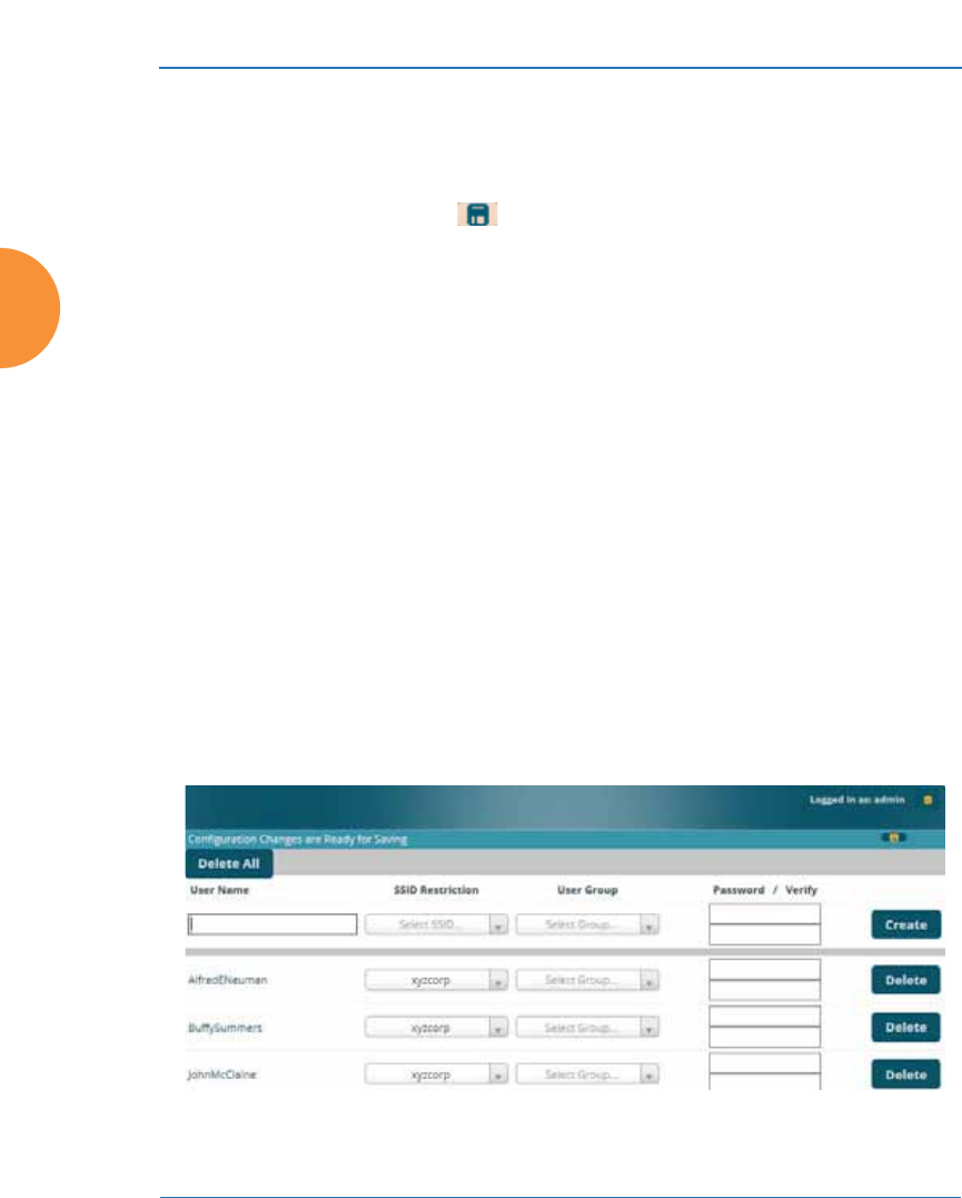
Wireless Access Point
258 Configuring the Wireless AP
g. Secondary Shared Secret / Verify Secret: If using a secondary
accounting server, enter the shared secret that it will be using, then re-
enter the shared secret to verify that you typed it correctly.
6. Click the Save button if you wish to make your changes permanent.
See Also
Admin Management
Global Settings
Internal Radius
Access Control List
Management Control
Security
Understanding Groups
Internal Radius
This window allows you to define the parameters for the AP’s internal RADIUS
server for user authentication. However, the internal RADIUS server will only
authenticate wireless clients that want to associate to the AP. This can be useful if
an external RADIUS server is not available. To set up the internal RADIUS server,
you must choose Internal Radius as the Authentication Server Mode in “Global
Settings” on page 250.
Figure 145. Internal RADIUS Server

Wireless Access Point
Configuring the Wireless AP 259
Procedure for Creating a New User
1. User Name: Enter the name of the user that you want to authenticate to
the internal RADIUS server. You may enter up to 1000 users (up to 256 on
the XR-500 Series, or up to 480 on two-radio APs).
2. SSID Restriction: (Optional) If you want to restrict this user to
associating to a particular SSID, choose an SSID from the pull-down list.
3. User Group: (Optional) If you want to make this user a member of a
previously defined user group, choose a group from the pull-down list.
This will apply all of the user group’s settings to the user. See
“Understanding Groups” on page 304.
4. Password: (Optional) Enter a password for the user.
5. Verify: (Optional) Retype the user password to verify that you typed it
correctly.
6. Click on the Create button to add the new user to the list.
Procedure for Managing Existing Users
1. SSID Restriction: (Optional) If you want to restrict a user to associating
to a particular SSID, choose an SSID from its pull-down list.
2. User Group: (Optional) If you want to change the user’s group, choose a
group from the pull-down list. This will apply all of the user group’s
settings to the user. See “Understanding Groups” on page 304.
3. Password: (Optional) Enter a new password for the selected user.
#Clients using PEAP may have difficulty authenticating to the AP using the
Internal RADIUS server due to invalid security certificate errors. To
prevent this problem, the user may disable the Validate Server Certificate
option on the station. Do this by displaying the station’s wireless devices and
then displaying the properties of the desired wireless interface. In the
security properties, disable Validate server certificate. In some systems,
this may be found by setting the authentication method to PEAP and
changing the associated settings.

Wireless Access Point
260 Configuring the Wireless AP
4. Verify Password: (Optional) Retype the user password to verify that you
typed it correctly.
5. If you want to delete one or more users, click their Delete buttons.
6. Click the Save button if you wish to make your changes permanent.
See Also
Admin Management
External Radius
Global Settings
Access Control List
Management Control
Security
Understanding Groups
Active Directory
This window allows you to configure 802.1x user authentication without needing
to set up and use an External Radius server. The AP performs authentication by
utilizing an Active Directory server that you have deployed within your network
domain.
This window configures the settings required to connect to the Active Directory
server. Additionally, Active Directory Test Tools are provided to ease the process
of validating proper communication between the Active Directory server and the
AP.
To use the Active Directory settings on this page you must choose Active
Directory as the Authentication Server Mode in “Global Settings” on page 250.
#XR-520/XR-1000 Series APs do not support Active Directory. You will
receive an error message if you attempt to configure this feature.
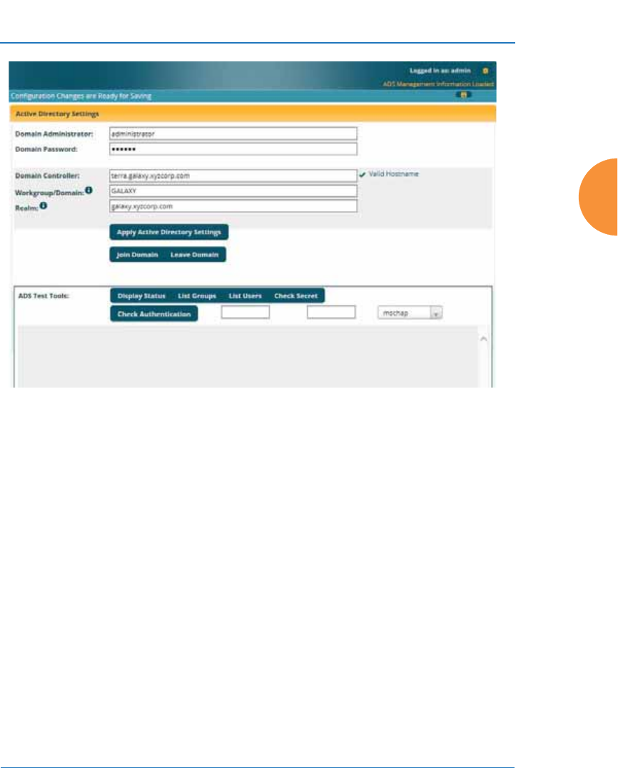
Wireless Access Point
Configuring the Wireless AP 261
Figure 146. Active Directory Server
Procedure for Use of an Active Directory Server
1. Choose Active Directory as the Authentication Server Mode in “Global
Settings” on page 250.
2. Domain Administrator: Enter the administrator account name for access
to the domain controller. The AP will use this (together with the
password) to create a machine account on the domain for the AP. This can
be the name of any account that can join a machine to the domain.
3. Domain Password: The password for the Domain Administrator entered
above.
4. Domain Controller: Enter the hostname to access the domain controller.
This cannot be entered as an IP address. The AP will check that it is able
to access the controller and place a checkmark to the right of the entry to
indicate that it has been validated. Note that the checkmark only appears
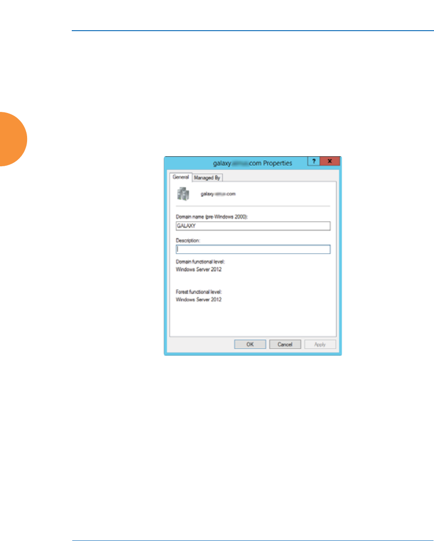
Wireless Access Point
262 Configuring the Wireless AP
after you have made a change requiring validation (i.e., entering a new
hostname or changing an existing entry to a different hostname). If you
return to this page at a later time, the checkmark will not be present.
5. Workgroup/Domain: Enter the Pre-Windows 2000 Domain name. This
can be found by opening the Active Directory Users and Computers.
Right click the domain in the left hand window and select Properties.
This will display the Domain name that should be entered.
Figure 147. Finding the Domain Name from Active Directory
6. Realm: Realm name (may be the same as the domain name). Workgroup
and Realm are both required. To find the Realm, open a command
window on the server and type
echo %userdnsdomain%
This will display the Realm.
7. Click Apply Active Directory Settings to use these settings.
8. You must click Join Domain to ask the domain controller to join the AP to
the domain. The AP is added to the list of computers in the workgroup.
The status of the request will be displayed in the area below the Test

Wireless Access Point
Configuring the Wireless AP 263
Tools. The domain controller will give the AP a secret that may be used as
a key to fetch information. The secret may be checked with the Check
Secret test tool, below. You may click Leave Domain to ask the domain
controller to remove the AP from the domain and revoke its secret.
9. You may use the tools below to check that the AP is able to access and use
the Active Directory successfully, or to troubleshoot any problems.
Active Directory Test Tools
10. Display Status: Displays detailed status information for the Active
Directory.
11. List Groups: Shows the groups defined in the Active Directory for this
Workgroup.
12. List Users: Shows the users defined in the Active Directory for this
Workgroup.
13. Check Secret: The continued validity of the secret granted by Join
Domain may be checked with this test tool.
14. Check Authentication: Enter a User name and Password. Select the Type
of encryption to be used (MSCHAP, NTLM, PAP, or PEAP-MSCHAPv2),
to check that it will work with the Active Directory server. Then click
Check Authentication to validate that the AP can authenticate the user
with the selected type of encryption.
See Also
Admin Management
External Radius
Internal Radius
Security
Understanding Groups
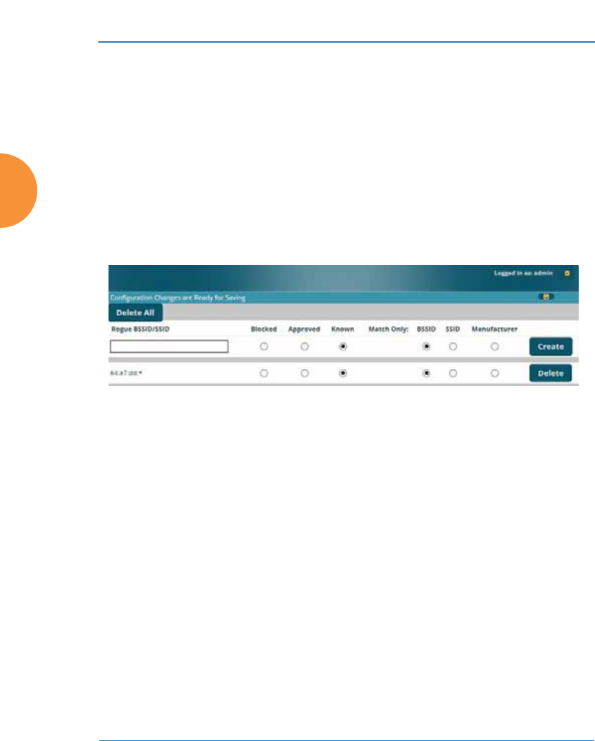
Wireless Access Point
264 Configuring the Wireless AP
Rogue Control List
This window allows you to set up a control list for rogue APs, based on a type
that you define. You may classify rogue APs as blocked, so that the AP will take
steps to prevent stations from associating with the blocked AP. See “About
Blocking Rogue APs” on page 376. The AP can keep up to 5000 list entries.
Figure 148. Rogue Control List
Procedure for Establishing Rogue AP Control
1. Rogue BSSID/SSID: Enter the BSSID, SSID, or manufacturer string to
match for the new rogue control entry. The Match Only radio buttons
specify what to match (e.g., the MAC address, SSID, or manufacturer).
You may use the “*” character as a wildcard to match any string at this
position. For example, 00:0f:7d:* matches any string that starts with
00:0f:7d:. Xirrus APs start with 00:0f:7d: or 50:60:28:00:0f:7d:*. By default,
the Rogue Control List contains two entries that match 00:0f:7d:* and
50:60:28:* and apply the classification Known to all Xirrus APs.
2. Rogue Control Classification: Enter the classification for the specified
rogue AP(s), either Blocked, Known or Approved.
#The RF Monitor > Intrusion Detection window provides an alternate
method for classifying rogues. You can list all Unknown stations and select
all the rogues that you’d like to set to Known or Approved, rather than
entering the SSID/BSSID as described below. See “Rogues” on page 120.

Wireless Access Point
Configuring the Wireless AP 265
3. Match Only: Select the match criterion to compare the Rogue BSSID/
SSID string against: BSSID, Manufacturer, or SSID. The BSSID field
contains the MAC address.
4. Click Create to add this rogue AP to the Rogue Control List.
5. Rogue Control List: If you want to edit the control type for a rogue AP,
just click the radio button for the new type for the entry: Blocked, Known
or Approved.
6. To delete rogue APs from the list, click their Delete buttons.
7. Click the Save button if you wish to make your changes permanent.
See Also
Network Map
Rogues
SSIDs
SSID Management
OAuth 2.0 Management
This window displays a list of tokens granted by the AP for access to its RESTful
API (see “API Documentation” on page 428 for a description of the features
available in the API). OAuth 2.0 is used to provide the tokens. The list will be
blank until tokens have been issued as described below. You may revoke (delete)
existing tokens from the list, if desired.
Xirrus APs use the OAuth 2.0 standard’s client credential grant model. This
allows you to use administrator account credentials to obtain a token to access
RESTful API on an individual AP. Please note that the AP will issue only one
token on behalf on of any administrator account at any given time. If you have a
need for multiple tokens, then the AP will need multiple administrator accounts.
Follow the steps below to obtain a token and use the RESTful API.

Wireless Access Point
266 Configuring the Wireless AP
Figure 149. OAuth 2.0 Management - Token List
Procedure for Obtaining a Token and Accessing RESTful API on the AP
1. Present User Credentials for a Permanent Token
A user-developed application must register by presenting the following
information to the URL below:
https://[AP hostname or IP address]/oauth/authorize
•grant_type: password
•username: username of an administrator account on the AP.
•client_id: username of an administrator account on the AP
(username and client_id must match).
•password: password for the same administrator account on the AP
The OAuth Authorization API provides a permanent token that the
application may use to access the RESTful API. This token remains valid
until the administrator revokes the token on the OAuth 2.0 Management
page, unless the token file somehow becomes corrupted or is removed
from the AP’s file system.
The token will be removed if the original account associated with it is
deleted.
2. Access the RESTful API
Once registration is completed and a permanent token has been
provided, your application may access the API using the client_id and
the token at the following URL:
https://[AP hostname or IP address]/api/v3/[api-name]

Wireless Access Point
Configuring the Wireless AP 267
Please see “API Documentation” on page 428 for a description of the
features available in the API.
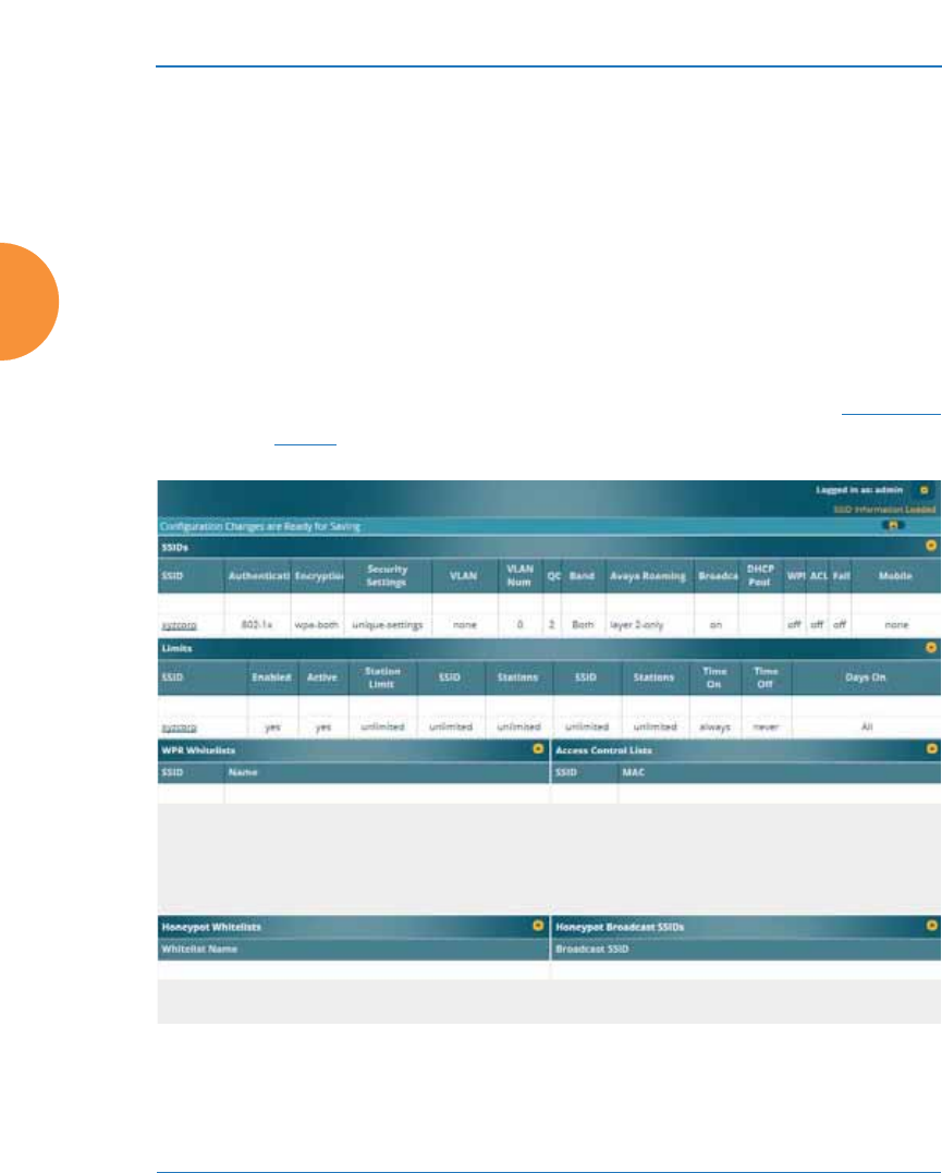
Wireless Access Point
268 Configuring the Wireless AP
SSIDs
This status-only window allows you to review SSID (Service Set IDentifier)
assignments. It includes the SSID name, whether or not an SSID is visible on the
network, any security and QoS parameters defined for each SSID, associated
VLAN IDs, radio availability, and DHCP pools defined per SSID. Click on an
SSID’s name to jump to the edit page for the SSID. There are no configuration
options available on this page, but if you are experiencing problems or reviewing
SSID management parameters, you may want to print this page for your records.
Figure 150. SSIDs
#For a complete discussion of implementing Voice over Wi-Fi on the AP, see
the Voice over Wireless Application Note in the Xirrus Resource
Center.

Wireless Access Point
Configuring the Wireless AP 269
The read-only Limits section of the SSIDs window allows you to review any
limitations associated with your defined SSIDs. For example, this window shows
the current state of an SSID (enabled or not), how much SSID and station traffic is
allowed, time on and time off, days on and off, and whether each SSID is
currently active or inactive.
For information to help you understand SSIDs and how multiple SSIDs are
managed by the Wireless AP, go to “Understanding SSIDs” on page 269 and the
Multiple SSIDs section of “Frequently Asked Questions” on page 522. For a
description of how QoS operates on the AP, see “Understanding QoS Priority on
the Wireless AP” on page 271.
SSIDs are managed with the following windows:
z
“SSID Management” on page 277
z
“Active IAPs” on page 298
z
“Per-SSID Access Control List” on page 299
z
“Honeypots” on page 300
z
“Personal Wi-Fi” on page 302
SSIDs are discussed in the following topics:
z
“Understanding SSIDs” on page 269
z
“Understanding QoS Priority on the Wireless AP” on page 271
z
“High Density 2.4G Enhancement—Honeypot SSID” on page 275
Understanding SSIDs
The SSID (Service Set Identifier) is a unique identifier that wireless networking
devices use to establish and maintain wireless connectivity. Multiple access points
on a network or sub-network can use the same SSIDs. SSIDs are case-sensitive
and can contain up to 32 alphanumeric characters (do not include spaces when
defining SSIDs).
Multiple SSIDs
A BSSID (Basic SSID) refers to an individual access point radio and its associated
clients. The identifier is the MAC address of the access point radio that forms the

Wireless Access Point
270 Configuring the Wireless AP
BSS. A group of BSSs can be formed to allow stations in one BSS to communicate
to stations in another BSS via a backbone that interconnects each access point.
The Extended Service Set (ESS) refers to the group of BSSIDs that are grouped
together to form one ESS. The ESSID (often referred to as SSID or “wireless
network name”) identifies the Extended Service Set. Clients must associate to a
single ESS at any given time. Clients ignore traffic from other Extended Service
Sets that do not have the same SSID.
Legacy access points typically support one SSID per access point. Wireless APs
support the ability to define and use multiple SSIDs simultaneously.
Using SSIDs
The creation of different wireless network names allows system administrators to
separate types of users with different requirements. The following policies can be
tied to an SSID:
z
The wireless security mode needed to join this SSID.
z
The wireless Quality of Service (QoS) desired for this SSID.
z
The wired VLAN associated with this SSID.
As an example, one SSID named accounting might require the highest level of
security, while another named guests might have low security requirements.
Another example may define an SSID named voice that supports voice over
Wireless LAN phones with the highest Quality of Service (QoS) definition. This
SSID might also forward traffic to specific VLANs on the wired network.
See Also
SSID Management
SSIDs
Understanding SSIDs
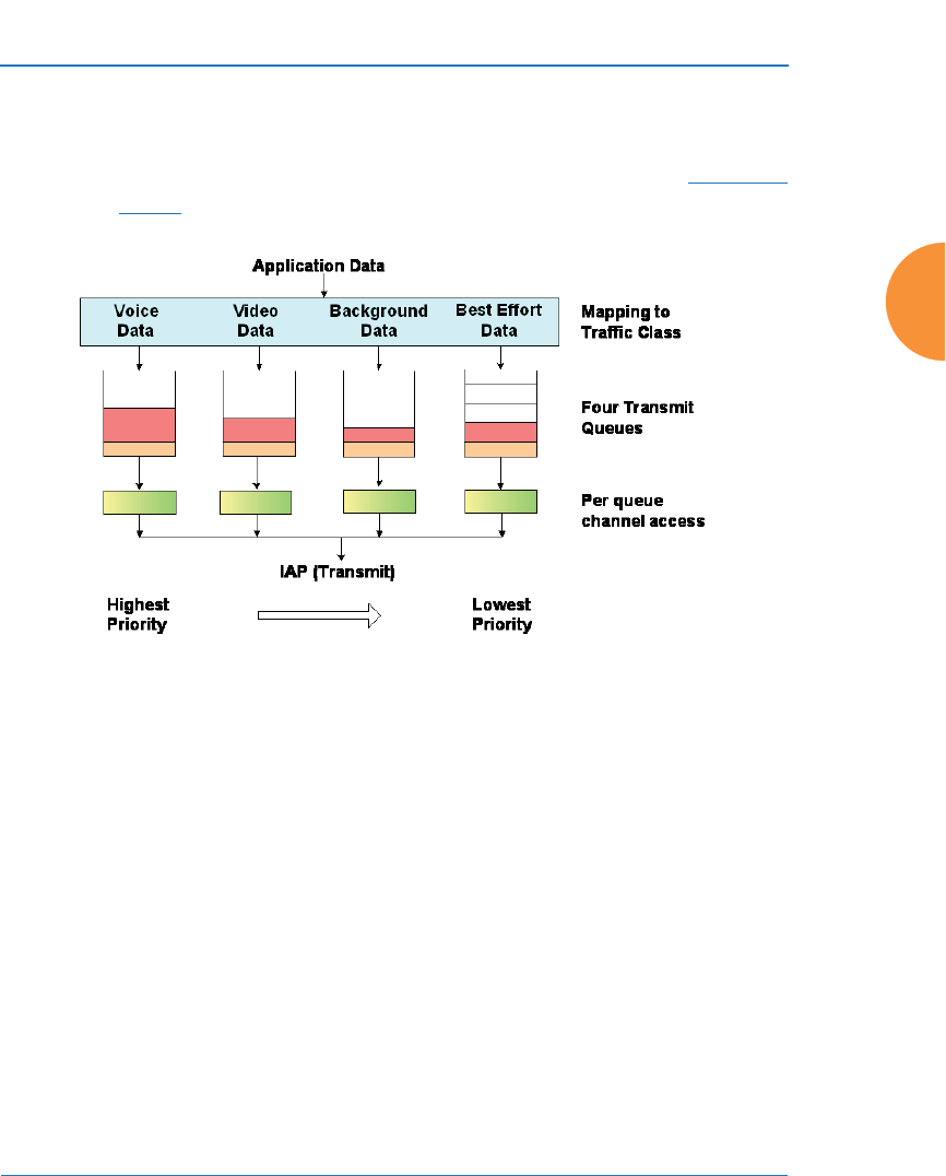
Wireless Access Point
Configuring the Wireless AP 271
Understanding QoS Priority on the Wireless AP
Figure 151. Four Traffic Classes
The Wireless AP’s Quality of Service Priority feature (QoS) allows traffic to be
prioritized according to your requirements. For example, you typically assign the
highest priority to voice traffic, since this type of traffic requires delay to be under
10 ms. The AP has four separate queues for handling wireless traffic at different
priorities, and thus it supports four traffic classes (QoS levels).
#For a complete discussion of implementing Voice over Wi-Fi on the AP, see
the Voice over Wireless Application Note in the Xirrus Resource
Center.
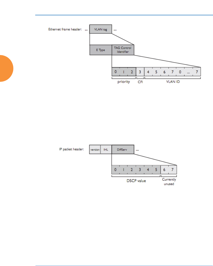
Wireless Access Point
272 Configuring the Wireless AP
Figure 152. Priority Level—IEEE 802.1p (Layer 2)
IEEE802.1p uses three bits in an Ethernet frame header to define eight priority
levels at the MAC level (Layer 2) for wired networks. Each data packet may be
tagged with a priority level, i.e., a user priority tag. Since there are eight possible
user priority levels and the AP implements four wireless QoS levels, user
priorities are mapped to QoS as described below.
Figure 153. Priority Level—DSCP (DiffServ - Layer 3)
Differentiated Services Code Point or DiffServ (DSCP) uses 6 bits in the IPv4 or
IPv6 packet header, defined in RFC2474 and RFC2475. The DSCP value classifies
a Layer 3 packet to determine the Quality of Service (QoS) required. DSCP
replaces the outdated Type of Service (TOS) field.
The description below describes how both of these priority levels are mapped to
the AP’s four traffic classes.

Wireless Access Point
Configuring the Wireless AP 273
End-to-End QoS Handling
Wired QoS - Ethernet Port:
z
Egress: Outgoing wired packets are IEEE 802.1p tagged at the Ethernet
port for upstream traffic, thus enabling QoS at the edge of the network.
z
Ingress: Incoming wired packets are assigned QoS priority based on their
SSID and 802.1p tag (if any), as shown in the table below. This table
follows the mapping recommended by IEEE802.11e.
FROM
AP QoS (Wireless) TO
Priority Tag 802.1p (Wired)
1 (Lowest priority) 1
00
2 (Default) 5
3 (Highest priority) 6
FROM
Priority Tag
802.1p (Wired)
TO
AP QoS
(Wireless) Typical Use
0 0 Best Effort
11 (Lowest
priority) Background — explicitly designated as
low-priority and non-delay sensitive
21Spare
3 0 Excellent Effort
42Controlled Load
52Video
6 3 Voice - requires delay <10ms

Wireless Access Point
274 Configuring the Wireless AP
Wireless QoS - Radios:
z
Each SSID can be assigned a separate QoS priority (i.e., traffic class) from
0 to 3, where 3 is highest priority and 2 is the default. See “SSID
Management” on page 277. If multiple SSIDs are used, packets from the
SSID with higher priority are transmitted first.
z
The AP supports IEEE802.11e Wireless QoS for downstream traffic.
Higher priority packets wait a shorter time before gaining access to the
air and contend less with all other 802.11 devices on a channel.
z
How QoS is set for a packet in case of conflicting values:
a. If an SSID has a QoS setting, and an incoming wired packet’s user
priority tag is mapped to a higher QoS value, then the higher QoS
value is used.
b. If a group or filter has a QoS setting, this overrides the QoS value
above. See “Groups” on page 304, and “Filters” on page 391.
c. Voice packets have the highest priority (see Voice Support, below).
d. If DSCP to QoS Mapping Mode is enabled, the IP packet is mapped
to QoS level 0 to 3 as specified in the DSCP Mappings table. This
value overrides any of the settings in cases a to c above.
In particular, by default:
•DSCP 8 is set to QoS level 1.
•DSCP 40 is typically used for video traffic and is set to QoS
level 2.
•DSCP 48 is typically used for voice traffic and is set to QoS
level 3—the highest level
7 (Highest
priority) 3 (Highest
priority) Network control
FROM
Priority Tag
802.1p (Wired)
TO
AP QoS
(Wireless) Typical Use

Wireless Access Point
Configuring the Wireless AP 275
•All other DSCP values are set to QoS level 0 (the lowest level—
Best Effort).
Packet Filtering QoS classification
z
Filter rules can be used to redefine the QoS priority level to override
defaults. See “Filter Management” on page 395. This allows the QoS
priority level to be assigned based on protocol, source, or destination.
Voice Support
z
The QoS priority implementation on the AP gives voice packets the
highest priority to support voice applications.
High Density 2.4G Enhancement—Honeypot SSID
Some situations pose problems for all wireless APs. For example, iPhones will
remember every SSID and flood the airwaves with probes, even when the user
doesn’t request or desire this behavior. In very high density deployments, these
probes can consume a significant amount of the available wireless bandwidth.
The AP “honeypot” SSID targets this problem. Simply create an SSID named
honeypot (lower-case) on the AP, with no encryption or authentication (select
None/Open). Once this SSID is created and enabled, it will respond to any station
probe looking for a named open SSID (unencrypted and unauthenticated) that is
not configured on the AP. It will make the station go through its natural
authentication and association process. See “Honeypots” on page 300.
The following SSIDs are excluded from being honeypotted:
z
Explicitly whitelisted SSIDs. See “Honeypots” on page 300.
z
SSIDs that are encrypted and/or authenticated.
z
SSIDs that are configured on this AP, whether or not they are enabled.
Traffic for a station connected to the honeypot SSID may be handled in various
ways using other AP features:
z
Traffic may be directed to WPR (captive portal) to display a splash page
or offer the user the opportunity to sign in to your service (see “Web Page
Redirect (Captive Portal) Configuration” on page 287);
z
Traffic may be filtered (see “Filters” on page 391);

Wireless Access Point
276 Configuring the Wireless AP
z
or it may be dead-ended by defining a specific dead-end VLAN on the
honeypot SSID to “trap” stations (see “VLANs” on page 213).
Use the honeypot feature carefully as it could interfere with legitimate SSIDs and
prevent clients from associating to another available network. You may define a
whitelist of allowed SSIDs which are not to be honeypotted. See “Honeypots” on
page 300. Th Honey pots page also allows you to change the SSID name that is
broadcast for the honeypot SSID.
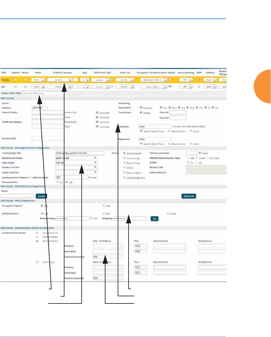
Wireless Access Point
Configuring the Wireless AP 277
SSID Management
This window allows you to manage SSIDs (create, edit, schedule, rename, and
delete), assign security parameters and VLANs on a per SSID basis, and configure
the Web Page Redirect (WPR captive portal) functionality.
Figure 154. SSID Management
Create new SSID
Configure parameters
Configure WPR
Configure WPA
Set traffic limits / usage schedule
Configure authentication server

Wireless Access Point
278 Configuring the Wireless AP
Procedure for Managing SSIDs
1. New SSID: To create a new SSID, enter a new SSID name. SSID names are
case sensitive and may only consist of the characters A-Z, a-z, 0-9, dash,
and underscore. You may create up to 16 SSIDs (up to 8 on the XR-500
Series). You may create a special SSID named honeypot (lower-case) to
reduce the amount of unnecessary traffic caused by stations probing for
open SSID names that they have learned in the past—see “High Density
2.4G Enhancement—Honeypot SSID” on page 275. In this case, a
Honeypot Service Whitelist Configuration section will appear below
(see Step 1 on page 301).
To rename an SSID or schedule a range of dates during which it may be
used, see “SSID Limits and Scheduling” on page 284.
SSID List (top of page)
2. SSID: Shows all currently assigned SSIDs. When you create a new SSID,
the SSID name appears in this table. Click any SSID in this list to select it.
3. Enabled: Check this box to activate this SSID or clear it to deactivate it.
Once the SSID is enabled, its availability is also controlled by settings in
“SSID Limits and Scheduling” on page 284.
4. Brdcast: Check this box to make the selected SSID visible to all clients on
the network. Although the Wireless AP will not broadcast SSIDs that are
hidden, clients can still associate to a hidden SSID if they know the SSID
name to connect to it. Clear this box if you do not want this SSID to be
visible on the network.
5. Band: Choose which wireless band the SSID will be beaconed on. Select
either 5 GHz — 802.11an, 2.4 GHz — 802.11bgn or Both.
6. VLAN ID / Number: (Optional) From the pull-down list, select a VLAN
or VLAN Pool that you want this traffic to be forwarded to on the wired
network. Select numeric to enter the number of a previously defined
VLAN in the Number field. See “VLANs” on page 213 and “VLAN
Pools” on page 215.

Wireless Access Point
Configuring the Wireless AP 279
7. QoS: (Optional) Select a value in this field for QoS (Quality of Service)
priority filtering. The QoS value must be one of the following:
•0 — The lowest QoS priority setting, where QoS makes its best effort
at filtering and prioritizing data, video and voice traffic without
compromising the performance of the network. Use this setting in
environments where traffic prioritization is not a concern.
•1 — Medium, with QoS prioritization aggregated across all traffic
types.
•2 — High, normally used to give priority to video traffic.
•3 — The highest QoS priority setting, normally used to give priority to
voice traffic.
The QoS setting you define here will prioritize wireless traffic for this
SSID over other SSID traffic, as described in “Understanding QoS Priority
on the Wireless AP” on page 271. The default value for this field is 2.
8. DHCP Pool: If you want to associate an internal DHCP pool to this SSID,
choose the pool from the pull--down list. An internal DHCP pool must be
created before it can be assigned. To create an internal DHCP pool, go to
“DHCP Server” on page 200.
9. DHCP Option: When this option is enabled, the AP snoops station
DHCP requests and inserts relay agent information into these DHCP
packets (option 82, in the CIRCUIT-ID sub-option). Information inserted
includes AP MAC address and SSID name. You may use this option here
or on the Tunnel Management page, but not in both places. Information is
inserted as a colon-separated text string in the CIRCUIT ID value field, in
this format: [AP_MAC]:[SSID]
[AP_MAC] length = 17 (aa-bb-cc-dd-ee-ff)
[SSID] length = length of SSID name
Example: aa-bb-cc-dd-ee-ff:mySSID
Note that the MAC address uses dashes as separators, and that format is
different than that used for Option 82 with Tunnels.

Wireless Access Point
280 Configuring the Wireless AP
10. Filter List: If you wish to apply a set a filters to this SSID’s traffic, select
the desired Filter List. See “Filters” on page 391.
11. Authentication: The following authentication options are available (only
valid encryption/authentication combinations are offered):
•Open: This option provides no authentication and is not
recommended.
•RADIUS MAC: Uses an external RADIUS server to authenticate
stations onto the wireless network, based on the user’s MAC address.
Accounting for these stations is performed according to the
accounting options that you have configured specifically for this SSID
or globally (see Step 13 below).
•802.1x: Authenticates stations onto the wireless network via a
RADIUS server using 802.1x with EAP. The RADIUS server can be
internal (provided by the Wireless AP) or external.
12. Encryption: Choose the encryption that will be required — specific to this
SSID — either None, WEP, WPA, WPA2 or WPA-Both. The None option
provides no security and is not recommended; WPA2 provides the best
Wi-Fi security.
Each SSID supports only one encryption type at a time (except that WPA
and WPA2 are both supported on an SSID if you select WPA-Both). If you
need to support other encryption types, you must define additional
SSIDs. The encryption used with WPA or WPA2 is selected in “Global
Settings” on page 250. For an overview of the security options, see
“Security Planning” on page 56 and “Understanding Security” on
page 226.
13. Global: Check this box if you want this SSID to use the security settings
established at the global level (see “Global Settings” on page 250). Clear
this box if you want the settings established here to take precedence.
#If this SSID is on a VLAN, the VLAN must have management turned on in
order to pass CHAP authentication challenges from the client station to the
RADIUS server.
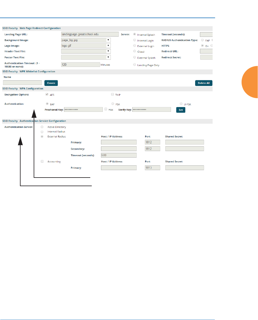
Wireless Access Point
Configuring the Wireless AP 281
.
Figure 155. SSID Management—Encryption, Authentication, Accounting
Additional sections will be displayed to allow you to configure
encryption, authentication server, and RADIUS accounting settings.
•The WPA Configuration encryption settings have the same
parameters as those described in “Procedure for Configuring
Network Security” on page 250.
The U-PSK (User-PSK) Authentication settings are only used in
conjunction with XMS-Cloud’s EasyPass Onboarding Portals. XMS-
Cloud automatically configures this setting for an SSID when you
create an Onboarding portal and you assign that SSID to the portal.
Thus, you should not normally change this setting manually. Note
that the User-PSK settings are only available here, on the SSID
Configure Radius, Accounting
Set Encryption

Wireless Access Point
282 Configuring the Wireless AP
Management page (i.e., they are configured per SSID rather than in
Global Settings).
EasyPass Onboarding facilitates “Bring Your Own Device (BYOD)”
usage. XMS-Cloud’s onboarding lets you create user accounts in
advance, and a user can self-register a number of devices simply by
connecting to the wireless network from each device. Each user
account is assigned a User-Preshared Key (U-PSK) to be used for
registering each device and accessing the wireless network.
U-PSK should only be enabled for an SSID that is assigned to an
XMS-Cloud EasyPass Onboarding portal. XMS-Cloud will also
automatically generate a unique Preshared Key for each user account.
U-PSK Cache Timeout (minutes)—this local cache on the AP stores
the station’s preshared key that was authenticated by the cloud.
The cache saves time the next time that the station associates to the
AP, since there is no need to query the U-PSK cloud server again.
U-PSK Cache Timeout specifies how long the cached entry is used
before it must be re-validated.
U-PSK Server Error specifies what to do if the U-PSK server in the
cloud cannot be accessed to check station authentication status. You
may Allow station traffic if the server is unavailable, or Block it.
•To configure Active Directory settings, see “Active Directory” on
page 260).
•The External RADIUS and Accounting settings are configured in the
same way as for an external RADIUS server (see “Procedure for
Configuring an External RADIUS Server” on page 255). Note that
external RADIUS servers may be specified using IP addresses or
domain names.
14. Roaming: For this SSID, select whether to enable fast roaming between
IAPs or APs at L2&L3 (Layer 2 and Layer 3), at L2 (Layer 2 only), or
disable roaming (Off). You may only select fast roaming at Layers 2 and 3
if this has been selected in Global Settings. See “Understanding Fast
Roaming” on page 312.

Wireless Access Point
Configuring the Wireless AP 283
15. WPR (Web Page Redirect, also called captive portal): Check the checkbox
to enable the Web Page Redirect functionality, or clear it to disable this
option. If enabled, WPR configuration fields will be displayed under the
SSID Limits section. This feature may be used to provide an alternate
mode of authentication, or to simply display a splash screen when a user
first associates to the wireless network. After that, it can (optionally)
redirect the user to an alternate URL. For example, some wireless devices
and users may not have a correctly configured 802.1x (RADIUS)
supplicant. Utilizing WPR’s Web-based login, users may be authenticated
without using an 802.1x supplicant. See “Web Page Redirect (Captive
Portal) Configuration” on page 287 for details of WPR usage and
configuration. If your venue is using Purple WiFi for guest access, see
also “Web Page Redirect for Purple WiFi Venues” on page 294.
You may specify “Whitelist” entries—a list of web sites to which users
have unrestricted access, without needing to be redirected to the WPR
page first. See “Whitelist Configuration for Web Page Redirect” on
page 293 for details.
16. Fallback: Network Assurance checks network connectivity for the AP.
When Network Assurance detects a failure, perhaps due to a bad link or
WDS failure, if Fallback is set to Disable the AP will automatically
disable this SSID. This will disassociate current clients, and prevent new
clients from associating. Since the AP’s network connectivity has failed,
this gives clients a chance to connect to other, operational parts of the
wireless network. No changes are made to WDS configuration. See Step a
on page 243 for more information on Network Assurance.
17. Mobile Device Management (MDM): If you are an AirWatch customer
and wish to have AirWatch manage mobile device access to the wireless
network on this SSID, select AirWatch from the drop-down list. Before
selecting this option, you must configure your AirWatch settings. See
“AirWatch” on page 406.
#When using WPR, it is particularly important to adhere to the SSID
naming restrictions detailed in Step 1.

Wireless Access Point
284 Configuring the Wireless AP
The lower part of the window contains a few sections of additional settings to
configure for the currently selected SSID, depending on the values chosen for the
settings described above.
z
“SSID Limits and Scheduling” on page 284
z
“Web Page Redirect (Captive Portal) Configuration” on page 287
z
“Whitelist Configuration for Web Page Redirect” on page 293
z
“WPA Configuration” on page 297
z
“Authentication Service Configuration” on page 297
SSID Limits and Scheduling
See “Group Limits” on page 309 for a discussion of the interaction of SSID limits
and group limits. To eliminate confusion, we recommend that you configure one
set of limits or the other, but not both.
18. Stations: Enter the maximum number of stations allowed on this SSID.
This step is optional. Note that the IAPs - Global Settings window also
has a station limit option — Max Station Association per IAP, and the
windows for Global Settings .11an and Global Settings .11bgn also have
Max Stations settings. If multiple station limits are set, all will be
enforced. As soon as any limit is reached, no new stations can associate
until some other station has terminated its association.
19. Overall Traffic: Choose Unlimited if you do not want to place a
restriction on the traffic for this SSID, or enter a value in the Packets/Sec
field to force a traffic restriction.
20. Traffic per Station: Choose Unlimited if you do not want to place a
restriction on the traffic per station for this SSID, or enter a value in the
Packets/Sec field or the Kbps field to force a traffic restriction. If you set
both values, the AP will enforce the limit it reaches first.
#Note that you cannot use MDM and WPR on the same SSID.

Wireless Access Point
Configuring the Wireless AP 285
21. Rename SSID: Use this field if you wish to change the name of an SSID
without changing any of its other settings. For example, a convention
center might wish to change the SSID name based on the name of the
current exhibition.
Scheduling
22. Days Active: Choose Everyday if you want this SSID to be active every
day of the week, or select only the specific days that you want this SSID to
be active. Days that are not checked are considered to be the inactive
days.
23. Time Active: Choose Always if you want this SSID active without
interruption, or enter values in the Time On and Time Off fields to limit
the time that this SSID is active.
24. Date on: Use this and the following two fields for SSID Scheduling—this
lets you set up an SSID in advance and specify a period of time for the
SSID to be in service. For example, a convention center might wish to set
up SSIDs ahead of time for exhibitions that are scheduled for the next six
months, and have each SSID be used only for the specified period.
The SSID must be Enabled (see Step 1 on page 278), or the scheduling
settings will be ignored. Note that once the SSID has reached its
scheduled time and is in service, it will then obey the settings for Days
Active and Time Active above.
Set Date on to none (the default) if you don’t want this SSID to be
delayed until later—that is, it will be put in service starting immediately.
Select Specific Date & Time to have the SSID start become active at the
specified date and time. Use the format YYYY-MM-DD [HH:MM], where
time (hour and minute) is optional. For example, enter 2016:09:29 08:00.
Use After Duration to delay for the specified amount of time in days,
hours, and minutes, before the SSID is in service (use the format
DD HH:MM, including the hours and minutes). For example, to have the
SSID become valid after one day, one hour and 30 minutes have passed,
enter 1 01:30.

Wireless Access Point
286 Configuring the Wireless AP
25. Use Date off to specify a date to take the SSID out of service without
deleting it. At the specified date, the AP will turn the Enabled flag off.
Leave Expiration and Date off set to none (the default) if you want this
SSID to remain in service indefinitely after its scheduled start. Use
Specific Date & Time to take the SSID out of service at the specified date
and time. Use the format YYYY-MM-DD [HH:MM], where time (hour
and minute) is optional. For example, enter 2016:09:29 18:00. Use After
Duration to keep the SSID in service for the specified amount of time in
days, hours, and minutes (use the format DD [HH:MM], where hours and
minutes are optional).
26. Use Expiration to specify a date to delete this SSID when it is taken out of
service at the specified date (i.e., this option cleans up after itself when it
reaches the expiration time). Leave Expiration and Date off set to none
(the default) if you want this SSID to remain in service indefinitely after
its scheduled start. Use Specific Date & Time to delete the SSID at the
specified date and time. Use the format YYYY-MM-DD [HH:MM], where
time (hour and minute) is optional. For example, enter 2016:09:29 18:00.
Use After Duration to keep the SSID in service for the specified amount
of time in days, hours, and minutes (use the format DD [HH:MM], where
hours and minutes are optional).
27. Web Page Redirect Configuration: see “Web Page Redirect (Captive
Portal) Configuration” on page 287.
28. To delete an SSID, click its Delete button .
29. Click the Save button if you wish to make your changes permanent.
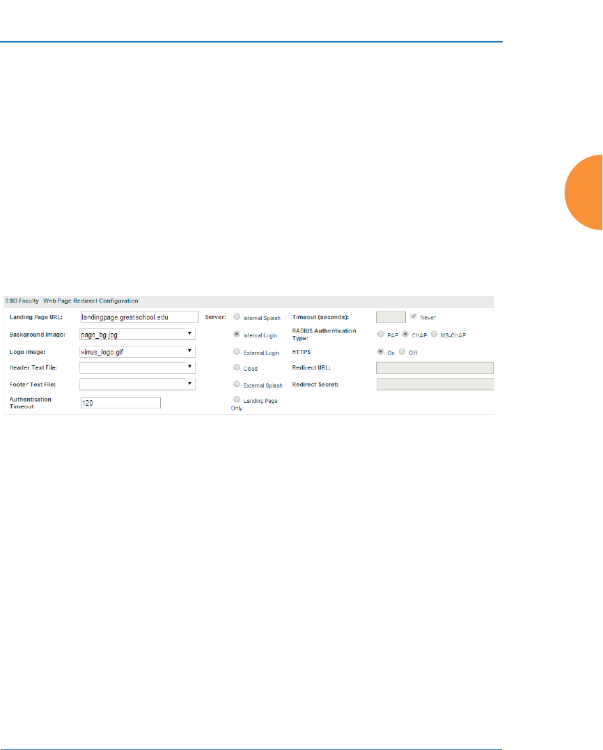
Wireless Access Point
Configuring the Wireless AP 287
Web Page Redirect (Captive Portal) Configuration
If you enable WPR, the SSID Management window displays additional fields that
must be configured.
If enabled, WPR displays a splash or login page when a client associates to the
wireless network and opens a browser to any URL (provided the URL does not
point to a resource directly on the client’s device). The user-requested URL is
captured, the user’s browser is redirected to the splash or login page, and then the
browser is redirected either to your specified landing page, if any, or else back to
the captured URL. The landing page may be specified for a user group as well.
See “Group Management” on page 306. Note that if you change the management
HTTPS port, WPR uses that port, too. See “HTTPS” on page 242.
Figure 156. WPR Internal Splash Page Fields (SSID Management)
Note that when clients roam between APs, their WPR Authentication will follow
them so that re-authentication is not required.
You may select among several different modes for use of the Web Page Redirect
feature, each displaying a different set of parameters that must be entered. For
each of these modes, set Authentication Timeout to the length of time (in
minutes) that an association using the captive portal will remain valid after a user
is disconnected. If a user session is interrupted, say if a mobile device goes into
power-save mode or a user closes a laptop lid, the user will not have to
reauthenticate unless the length of the disconnection is longer than the timeout.
The default is 120 minutes. The maximum timeout is 10080 minutes (seven days).
Web Page Redirect offers the following modes.
z
Internal Login page

Wireless Access Point
288 Configuring the Wireless AP
This option displays a login page (residing on the AP) instead of the first
user-requested URL. There is an upload function that allows you to
replace the default login page, if you wish. Please see “Web Page Redirect
(Captive Portal)” on page 423 for more information.
To set up internal login, set Server to Internal Login. Set HTTPS to On
for a secure login, or select Off to use HTTP. You may also customize the
login page with logo and background images and header and footer text.
See “Customizing an Internal Login or Splash page” on page 292.
The user name and password are obtained by the login page.
Authentication occurs according to your selection—PAP, CHAP, or
MS-CHAP. Note that if you select CHAP, then you cannot select Active
Directory in “Authentication Service Configuration” on page 297.
After authentication, the browser is redirected back to the captured URL.
If you want the user redirected to a specific landing page instead, enter its
address in Landing Page URL.
z
Internal Splash page
This option displays a splash page instead of the first user-requested
URL. The splash page files reside on the AP. Note that there is an upload
function that allows you to replace the default splash page, if you wish.
Please see “Web Page Redirect (Captive Portal)” on page 423 for more
information. You may also customize the splash page with logo and
background images and header and footer text. See “Customizing an
Internal Login or Splash page” on page 292.
To use an internal splash page, set Server to Internal Splash. Enter a
value in the Timeout field to define how many seconds the splash screen
is displayed before timing out, or select Never to prevent the page from
timing out automatically. After the splash page, the user is redirected to
the captured URL. If you want the user redirected to a specific landing
page instead, enter its address in Landing Page URL.
#Both the Internal Login and External Login options of WPR perform
authentication using your configured RADIUS servers.

Wireless Access Point
Configuring the Wireless AP 289
z
External Login page
This option redirects the user to a login page on an external web server
for authentication, instead of the first user-requested URL. Login
information (user name and password) must be obtained by that page,
and returned to the AP for authentication.
Authentication occurs according to your configured RADIUS
information. These parameters are configured as described in “Procedure
for Configuring Network Security” on page 250, except that the RADIUS
Authentication Type is selected here, as described below. After
authentication, the browser is redirected back to the captured URL. If you
want the user redirected to a specific landing page instead, enter its
address in Landing Page URL.
To set up external login page usage, set Server to External Login. Enter
the URL of the external web server in Redirect URL, and enter that
server’s shared secret in Redirect Secret.
Select the RADIUS Authentication Type. This is the protocol used for
authentication of users, CHAP or PAP (the default).
•Password Authentication Protocol (PAP), is a simple protocol. PAP
transmits ASCII passwords over the network “in the clear”
(unencrypted) and is therefore considered insecure.
•Challenge-Handshake Authentication Protocol (CHAP) is a more
secure Protocol. The login request is sent using a one-way hash
function.
z
External Splash page
This option displays a splash page instead of the first user-requested
URL. The splash page files reside on an external web server.
To set up external splash page usage, set Server to External Splash. Enter
the URL of the external web server in Redirect URL, and enter that
server’s shared secret in Redirect Secret.

Wireless Access Point
290 Configuring the Wireless AP
After the splash page, the user is redirected to the captured URL. If you
want the user redirected to a specific landing page instead, enter its
address in Landing Page URL.
z
Cloud
This option is only used in conjunction with the Guest Access feature in
XMS-Cloud Next Generation (XMS-9500-CL-x). If enabled, Cloud
redirects the user to a login page hosted in the cloud by XMS for
authentication, instead of the first user-requested URL. Login information
(user name and password) is obtained by that Cloud Login page, and
returned to the AP for authentication.
After authentication, the browser is redirected back to the captured URL.
If you want the user redirected to a specific landing page instead, enter its
address in Landing Page URL.
Cloud Login settings on the AP are entirely managed automatically by
XMS-Cloud, based on the configuration that the network administrator
has selected there. You should not make any changes to the following settings
configured by XMS. XMS will set Server to Cloud Login and set the values
of Redirect URL and Redirect Secret.
z
Landing Page Only
This option redirects the user to a specific landing page. If you select this
option, enter the desired address in Landing Page URL.
z
Personal Wi-Fi
This option is only used in conjunction with the EasyPass Personal portal
feature in XMS-Cloud Next Generation (XMS-9500-CL-x). Personal Wi-Fi
settings on the AP are entirely managed automatically by XMS-Cloud,
based on the settings that have been selected there. You should not make
any changes to the settings configured by XMS. When an XMS-Cloud
administrator creates an EasyPass Personal portal, XMS configures the
corresponding SSID on the AP to enable Personal Wi-Fi and the Cloud
WPR setting. XMS-Cloud also sets the values on the Personal Wi-Fi page.

Wireless Access Point
Configuring the Wireless AP 291
When users connect to the SSID that runs the EasyPass Personal portal,
they are redirected to a login page hosted in the cloud by XMS. After
successful authentication, a user is redirected to a Personal Wi-Fi setup
page to specify necessary parameters for this feature: a personal SSID
name, preshared key (PSK) and expiration date. This personal SSID is
configured on APs by XMS-Cloud. Users will typically set up the same
SSID name and PSK that they use at home, which their smartphones,
tablets, and other personal devices are already configured to connect with
automatically. For example, if a hotel offers Xirrus Personal Wi-Fi, guests
will be able to set up SSIDs that mimic their home networks. Their
devices will automatically connect securely for the duration of the guest’s
stay (until the personal SSID expires). See “Personal Wi-Fi” on page 302
for more details.
The personal SSID is created with the default values shown below.
Encryption / Authentication: 8WPA2-PSK/02.1x Broadcast: on
Band: both VLAN Name/Pool: none
QoS: 2 Filter list: none
Roaming: L2 WPR: off
Fallback: off Mobile Device Mgmt: none
ACL Mode: off
SSID Active: yes SSID expiration: per user setting in XMS-C
DHCP Pool: uses SSID’s name, see below DHCP Opt: off
A DHCP pool is created for each personal SSID using the SSID Name. NAT is enabled, and the IP
subnet is 192.168.1.0/24.
In IAP—Global Settings, Block Inter-Station Traffic is set to No.
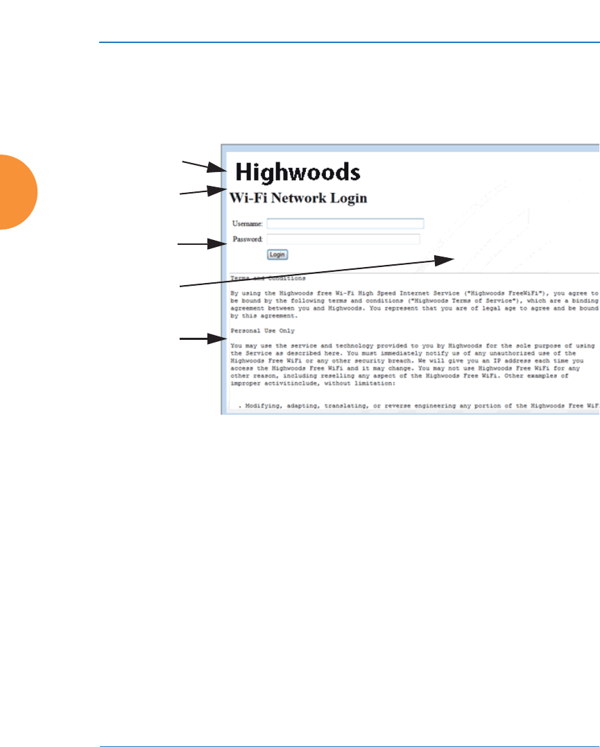
Wireless Access Point
292 Configuring the Wireless AP
Customizing an Internal Login or Splash page
You may customize these pages with a logo and/or background image, and
header and/or footer text, as shown below in Figure 157.
Figure 157. Customizing an Internal Login or Splash Page
z
Background Image — specify an optional jpg, gif, or png file to display in
the background of the page. Other customizations (logo, header, footer)
will overlay the background, so that it will not be visible in those areas.
z
Logo Image — specify an optional jpg, gif, or png file to display at the top
of the page.
z
Header Text File — specify an optional .txt file to display at the top of the
page (beneath the logo, if any).
z
Footer Text File — specify an optional .txt file to display at the bottom of
the page.
Logo
Internal
Login Page
Background
Footer
Header
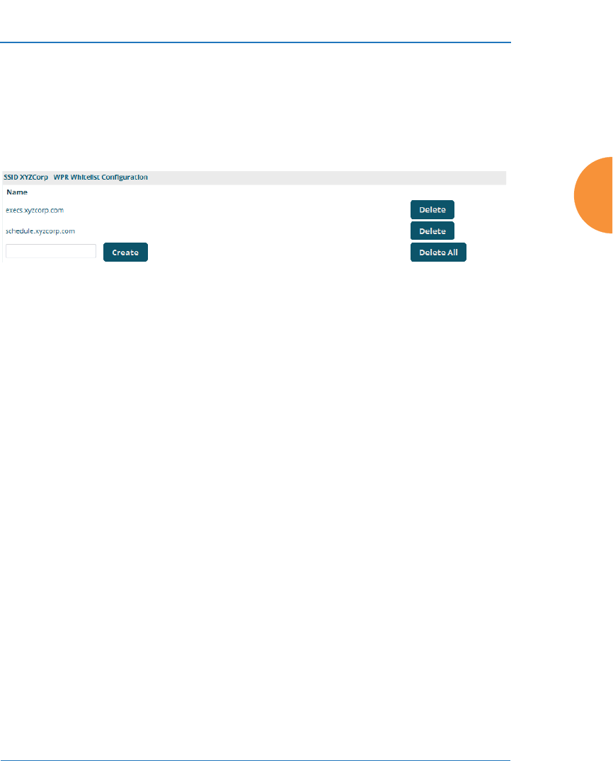
Wireless Access Point
Configuring the Wireless AP 293
Whitelist Configuration for Web Page Redirect
On a per-SSID basis, the whitelist allows you to specify Internet destinations that
stations can access without first having to pass the WPR (captive portal) login/
splash page. Note that a whitelist may be specified for a user group as well. See
“Group Management” on page 306.
Figure 158. Whitelist Configuration for WPR
To add a web site to the whitelist for this SSID, enter it in the provided field, then
click Create. You may enter an IP address or a domain name. Up to 32 entries may
be created.
Example whitelist entries:
z
Hostname: www.yahoo.com (but not www.yahoo.com/abc/def.html)
z
Wildcards are supported: *.yahoo.com
z
IP address: 121.122.123.124
Some typical applications for this feature are:
z
to add allowed links to the WPR page
z
to add a link to terms of use that may be hosted on another site
z
to allow embedded video on WPR page
Note the following details of the operation of this feature:
z
The list is configured on a per-SSID basis. You must have WPR enabled
for the SSID to see this section of the SSID Management page.
z
When a station that has not yet passed the WPR login/splash page
attempts to access one of the white-listed addresses, it will be allowed
access to that site as many times as requested.

Wireless Access Point
294 Configuring the Wireless AP
z
The station will still be required to pass through the configured WPR flow
for all other Internet addresses.
z
The whitelist will work against all traffic -- not just http or https
z
Indirect access to other web sites is not permitted. For example, if you
add www.yahoo.com to the whitelist, you can see that page, but not all
the ads that it attempts to display.
z
The whitelist feature does not cause traffic to be redirected to the whitelist
addresses.
Web Page Redirect for Purple WiFi Venues
Figure 159. Purple WiFi
Guest Access
Purple WiFi is a cloud-based solution that sets up a
WiFi hotspot in a business or venue. It offers a
number of features such as user analytics, filtering
of inappropriate content, marketing, and social
media options.
Once you have signed up with Purple WiFi, set up
APs as described below. For more details of
operation, see “Purple WiFi Client Login Process
Details” on page 296.
To deploy APs in a venue that uses Purple WiFi to
provide guest access, use the following WPR
(captive portal) configuration.
1. On the SSID Management Page, enable
WPR on each SSID that is to offer Purple
WiFi guest access.
2. Then set the following Web Page Redirect Configuration options:
•Server: select External Login.
•Landing Page URL: set this to the URL provided by Purple WiFi
when you set up your account with them.
•Redirect URL: set this to the URL provided by Purple WiFi when you
set up your account with them. For example:

Wireless Access Point
Configuring the Wireless AP 295
http://purpleportal.net/access/
•Redirect Secret: Enter the password provided to you by Purple WiFi.
3. In the next section on the same page, create WPR Whitelist
Configuration entries as directed by Purple WiFi for web sites that
should not be redirected. Note that if an asterisk is part of the entry, you
must include this character. For example:
*.purpleportal.net
*.facebook.com
api.twitter.com
connect.facebook.net
4. Set the Authentication Server for client access to be the server provided to
you by Purple WiFi:
•If you did not select Global in Step 13 on page 280, then the
Authentication Server will be specific to this SSID, rather than the
server used globally on the AP. In the section labeled Authentication
Service Configuration, enter the following:
•Set the Authentication Server type to External RADIUS.
•Enter the Host or IP Address, Port, and the Shared Secret
(password) of the Primary Server provided by Purple WiFi.
•If you did select Global in Step 13 on page 280, then the SSID uses the
Authentication Server that you defined on the Security > External
Radius Page for global use on the AP. This must be the server
provided to you by Purple WiFi. It will be used for all client
authentication, unless you define other SSIDs that don’t use the
global server.
On the Security > Global Settings Page:
•Set the Authentication Server Mode to External Radius.
On the Security > External Radius Page:
•Enter the Host Name or IP Address, Port, and the Shared Secret
(password) of the Primary Server provided by Purple WiFi.

Wireless Access Point
296 Configuring the Wireless AP
5. Regardless of whether you selected a global authentication server in Step
13 on page 280, you need the following setting for compatibility with
Purple WiFi. On the Security > External Radius Page, in the RADIUS
Attribute Formatting section:
•Set Called-Station-Id Attribute Format to Ethernet MAC.
Purple WiFi Client Login Process Details
This is an overview of the interaction between the AP and Purple WiFi when a
client connects. The client is not aware of any of these details and is led through
the process by Purple WiFi’s simple interface.
1. A client (smartphone, iPad, etc.) connects to an SSID at a Purple WiFi
customer site.
2. The SSID is configured for WPR. As soon as the client opens a browser, it
is redirected to the configured Purple WiFi portal page that was
configured in the AP External Login page, via the Redirect URL.
3. The AP contacts the Redirect URL along with the AP’s MAC address
(Ethernet MAC). This is used to match the Purple WiFi customer site
against a database of AP MAC addresses managed by Purple WiFi, which
delivers a customized splash page.
4. The Purple WiFi splash page prompts the end user to log into a social
media site.
5. Upon successful authorization at the social media site, a record is then
created in the Purple WiFi (External RADIUS) database for the client.
6. The Purple WiFi splash page then redirects the browser back to the login
script on the AP along with the authentication information (username/
password), and the AP then performs an external RADIUS authentication
request against the Purple WiFi RADIUS servers (as configured on the
AP).

Wireless Access Point
Configuring the Wireless AP 297
7. If RADIUS authenticates successfully, then the end user is given access to
the full Internet, outside of your internal network. Future connections to
the same Access Point are automatically authenticated with no user
action required.
WPA Configuration
If you set Encryption for this SSID to one of the WPA selections (Step 12 on
page 280) and you did not check the Global checkbox (Step 13), this section will
be displayed. The WPA Configuration encryption settings have the same
parameters as those described in “Procedure for Configuring Network Security”
on page 250.
Authentication Service Configuration
The RADIUS settings section will be displayed if you set Authentication (Step 11
on page 280) to anything but OPEN, and you set Encryption (Step 12) to anything
but WEP, and you did not check the Global checkbox (Step 13). This means that
you wish to set up a RADIUS server or Active Directory server to be used for this
particular SSID. If Global is checked, then the security settings (including the
RADIUS server, if any) established at the global level are used instead (see
“Global Settings” on page 250).
The RADIUS and accounting settings are configured in the same way as for an
external RADIUS server (see “Procedure for Configuring an External RADIUS
Server” on page 255). If you select Active Directory, then the settings are
configured in “Active Directory” on page 260. Note that if you select Active
Directory, then you cannot use CHAP authentication.
See Also
DHCP Server
External Radius
Global Settings
Internal Radius
Security Planning
SSIDs
Understanding QoS Priority on the Wireless AP
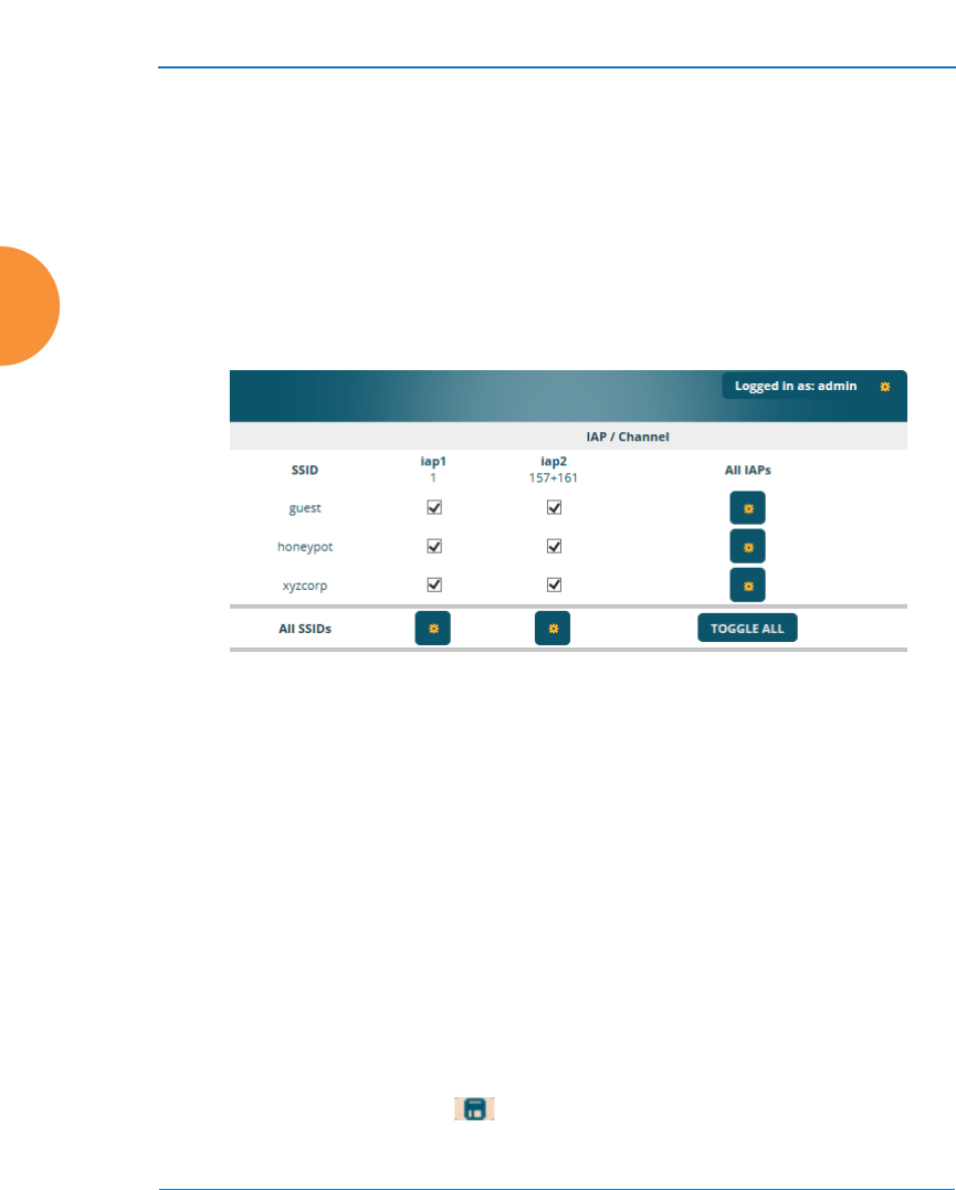
Wireless Access Point
298 Configuring the Wireless AP
AirWatch
Active IAPs
By default, when a new SSID is created, that SSID is active on all IAPs. This
window allows you to specify which IAPs will offer that SSID. Put differently,
you can specify which SSIDs are active on each IAP.
This feature is useful in conjunction with WDS. You may use this window to
configure the WDS link IAPs so that only the WDS link SSIDs are active on them.
Figure 160. Setting Active IAPs per SSID
Procedure for Specifying Active IAPs
1. SSID: For a given SSID row, check the IAPs that should offer that SSID to
clients. Uncheck any IAPs which should not offer that SSID.
2. All IAPs: This button, in the last column, may be used to allow or deny
this SSID on all IAPs, i.e., switch all IAPs between allow or deny.
3. All SSIDs: This button, in the bottom row, may be used to allow or deny
all SSIDs on this IAP.
4. Toggle All: This button, on the lower left, may be used to allow or deny
all SSIDs on all IAPs.
5. Click the Save button if you wish to make your changes permanent.
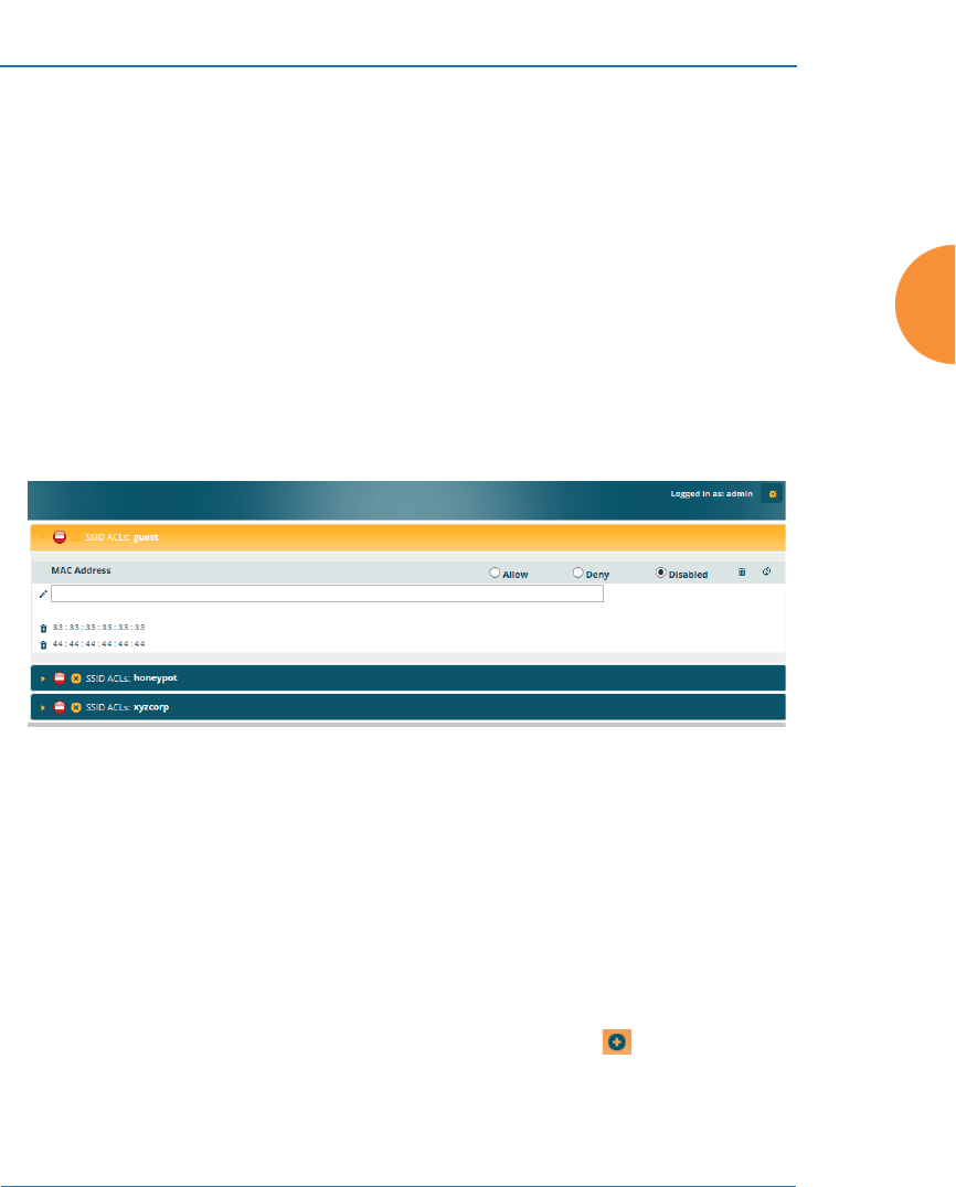
Wireless Access Point
Configuring the Wireless AP 299
Per-SSID Access Control List
This window allows you set up Access Control Lists (ACLs) on a per-SSID basis,
to control whether a station with a particular MAC address may associate to a
particular SSID. You may create access control list entries and delete existing
entries, and control the type of list (allow or deny).
There is one ACL per SSID, and you may select whether its type is an Allow list
or a Deny list, or whether use of this list is Disabled. You may create up to 1000
entries per SSID.
There is also a global ACL (see “Access Control List” on page 248). If the same
MAC address is listed in both the global ACL and in an SSID’s ACL, and if either
ACL would deny that station access to that SSID, then access will be denied.
Figure 161. Per-SSID Access Control List
Procedure for Configuring Access Control Lists
1. SSID: Select the line for the SSID whose ACL you wish to manage. Click
the line to hide or expand (display) the list.
2. Access Control List Type: Select Disabled to disable use of the Access
Control List for this SSID, or select the ACL type — either Allow or Deny.
•Allow: Only allows the listed MAC addresses to associate to the
AP. All others are denied. The plus symbol appears before
the SSID name for an allow list.

Wireless Access Point
300 Configuring the Wireless AP
•Deny List: Denies the listed MAC addresses permission to
associate to the AP. All others are allowed. The minus symbol
appears before the SSID name for a deny list.
•Disabled: A red dot appears before the SSID name for a
disabled list. A green dot appears before the SSID name for
an allow or deny list.
3. MAC Address: If you want to add a MAC address to the ACL for the
selected SSID, enter the new MAC address. You may use a wildcard (*)
for one or more digits to match a range of addresses. Delete: You may
delete selected MAC addresses from this list by clicking their Delete
buttons .
4. Click the Save button if you wish to make your changes permanent.
Honeypots
The honeypot SSID feature prevents the airwaves from being crowded with
probes for named SSIDs. These probes are automatically generated by some
popular wireless devices. When you create and enable a honeypot SSID on an AP,
it responds to any station probe looking for a named open SSID (unencrypted and
unauthenticated) that is not configured on the AP. For more details, see “High
Density 2.4G Enhancement—Honeypot SSID” on page 275.
This page allows you to create a honeypot SSID, enter a whitelist of SSID names
that are not to be honeypotted, and define alternate names for the SSID that will
be broadcast instead of “honeypot”.
#In addition to these lists, other authentication methods (for
example, RADIUS) are still enforced for users.
#Use the honeypot feature carefully as it could interfere with legitimate
SSIDs.
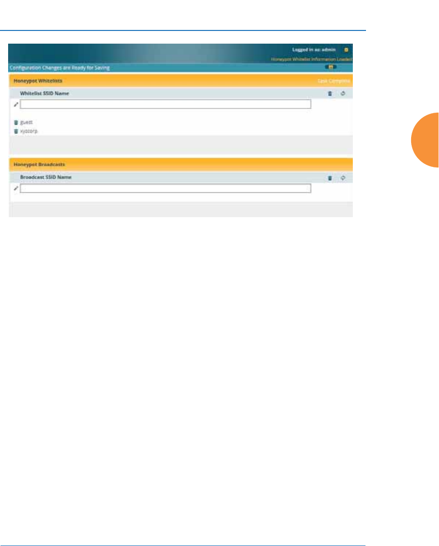
Wireless Access Point
Configuring the Wireless AP 301
Figure 162. Honeypot Whitelist
Procedure for Configuring Honeypot Whitelists
1. Create a honeypot: If you have not already created an SSID named
honeypot, you will be asked whether you wish to create one. Click Yes.
You must have an SSID named honeypot to use this feature.
2. Honeypot Whitelists: This section only appears if you have created an
SSID named honeypot. You may define a whitelist of allowed SSIDs
which are not to be honeypotted, as described in “High Density 2.4G
Enhancement—Honeypot SSID” on page 275. Type in each SSID name,
and click Create to add it to the whitelist. Up to 50 SSIDs may be listed.
The SSID names entered in this list are not case-sensitive.
You may use the “*” character as a wildcard to match any string at this
position. For example, xir* matches any string that starts with XIR or xir.
You may use a ? as a wildcard to match a single character by surrounding
the SSID name in quotes. For example, “xirru?” will match any six-
character long string that starts with xirru (again, the match is not case-
sensitive). If you do not use a wildcard, then the SSID name entered must
be matched exactly in order to be whitelisted (except that case is not
considered).
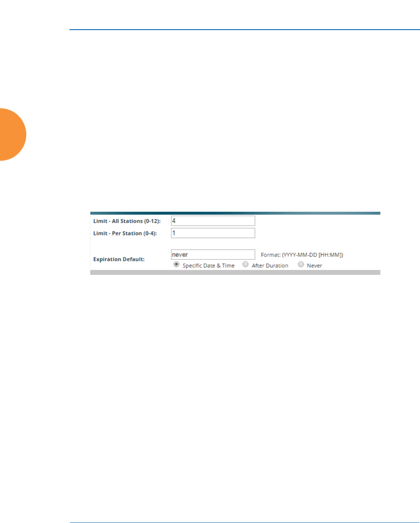
Wireless Access Point
302 Configuring the Wireless AP
3. Honeypot Broadcasts: This section only appears if you have created an
SSID named honeypot. You may define one or more alias names for this
SSID. They will be broadcast instead of the name honeypot.
Personal Wi-Fi
The settings on this page will apply to all of the Personal Wi-Fi SSIDs that are
created by users after they connect to an EasyPass Personal portal. See “Personal
Wi-Fi” on page 290. These settings are only used in conjunction with the EasyPass
Personal portal feature in XMS-Cloud Next Generation (XMS-9500-CL-x), and
they are entirely managed automatically by XMS-Cloud, based on the settings
that have been selected there. You should not make any changes to the settings
configured by XMS.
Figure 163. Personal Wi-Fi
Settings for Personal Wi-Fi
1. Limit - All Stations (0-12): the maximum number of personal SSIDs that
may exist on this AP at one time. The default value is 4.
2. Limit - Per Station (0-4): the maximum simultaneous number of personal
SSIDs that can be created by a single station. The default value is 1.
3. Expiration Default: the expiration time for a personal SSID—after this
time, the SSID will be deleted. Note that the user may specify an
expiration date for a particular personal SSID when it is set up. If
expiration times are specified both on this page and for a particular
personal SSID, the SSID will expire at whichever time occurs first.
You may enter a Specific Date & Time for the personal SSID to expire.
Use the format YYYY-MM-DD [HH:MM], where time (hour and minute)

Wireless Access Point
Configuring the Wireless AP 303
is optional. For example, enter 2016:09:29 08:00. If the hour and minute
are omitted, they are assumed to be 23:59.
Use After Duration to specify the length of time before the SSID expires,
in days, hours, and minutes. Use the format DD [HH:MM], where hours
and minutes are optional. For example, to have the SSID expire after one
day, one hour and 30 minutes have passed, enter 1 01:30.
Set Expiration to Never (the default) if you want this SSID to remain in
service indefinitely after its scheduled start.
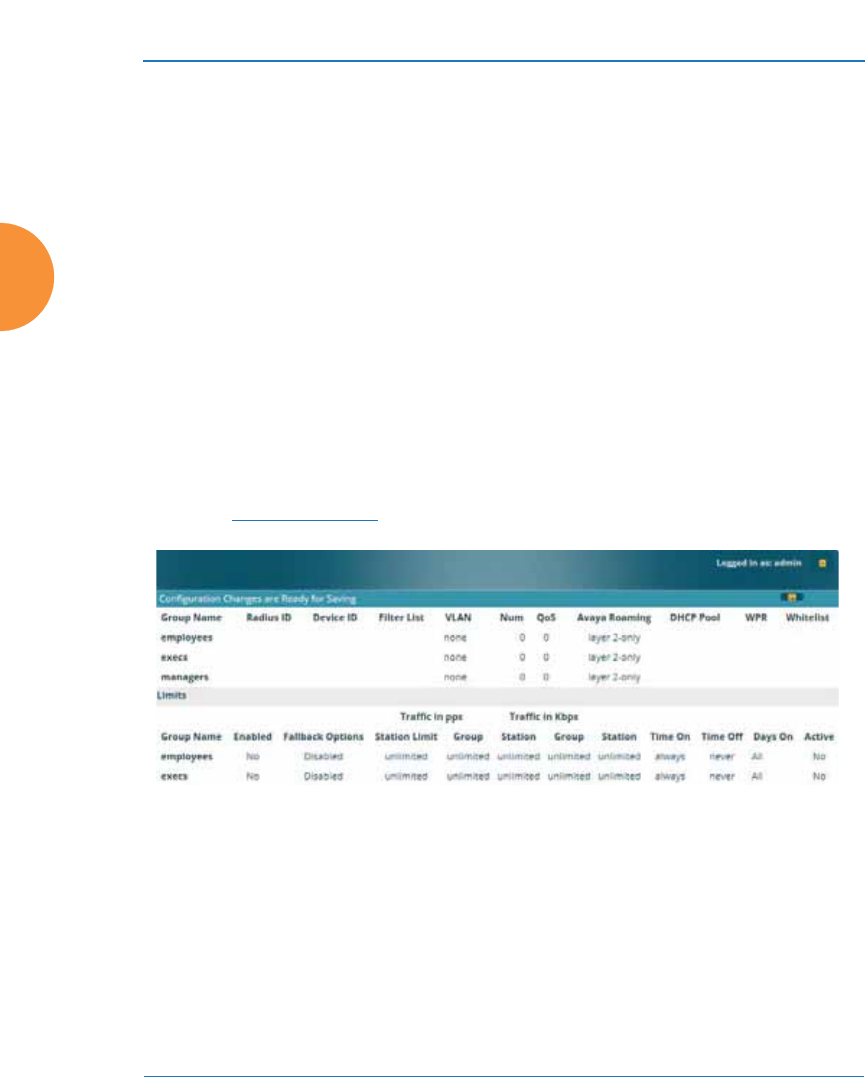
Wireless Access Point
304 Configuring the Wireless AP
Groups
This is a status-only window that allows you to review user (i.e., wireless client)
Group assignments. It includes the group name, Radius ID, Device ID, VLAN IDs
and QoS parameters and roaming layer defined for each group, and DHCP pools
and web page redirect information defined for the group. You may click on a
group’s name to jump to the edit page for the group. There are no configuration
options available on this page, but if you are experiencing problems or reviewing
group management parameters, you may want to print this page for your records.
The Limits section of this window shows any limitations configured for your
defined groups. For example, this window shows the current state of a group
(enabled or disabled), how much group and per-station traffic is allowed, time on
and time off, and days on and off.
For information to help you understand groups, see Understanding Groups
below. For an in-depth discussion, please see the User Groups Application Note in
the Xirrus Resource Center.
Figure 164. Groups
Understanding Groups
User groups allow administrators to assign specific network parameters to users
(wireless clients) through RADIUS privileges rather than having to map users to
an SSID tailored for that set of privileges. Groups provide flexible control over
user privileges without the need to create large numbers of SSIDs.
A group allows you to define a set of parameter values to be applied to selected
users. For example, you might define the user group Students, and set its VLAN,

Wireless Access Point
Configuring the Wireless AP 305
security parameters, web page redirect (WPR), and traffic limits. When a new user
is created, you can apply all of these settings just by making the user a member of
the group. The group allows you to apply a uniform configuration to a set of users
in one step.
In addition, you can restrict the group so that it only applies its settings to group
members who are connecting using a specific device type, such as iPad or phone.
Thus, you could define a group named Student-Phone with Device ID set to
Phone, and set the group’s VLAN Number to 100. This group’s settings will only
be applied to group members who connect using a phone, and they will all use
VLAN 100. Note that settings for the group in the RADIUS server will override
any settings on this WMI page.
Almost all of the parameters that can be set for a group are the same as SSID
parameters. This allows you to configure features at the user group level, rather
than for an entire SSID. If you set parameter values for an SSID, and then enter
different values for the same parameters for a user group, the user group values
have priority (i.e., group settings will override SSID settings).
Group names are case-sensitive and can contain up to 32 alphanumeric characters
(do not include spaces when defining Groups).
Using Groups
User accounts are used to authenticate wireless clients that want to associate to
the AP. These accounts are established in one of two ways, using the Security>
Internal Radius window or the Security> External Radius window. In either
case, you may select a user group for the user, and that user group’s settings will
apply to the user:
z
Internal Radius — when you add or modify a user entry, select a user
group to which the user will belong.
z
External Radius — when you add or modify a user account, specify the
Radius ID for the user group to which the user will belong. This must be
the same Radius ID that was entered in the Group Management window.
When the user is authenticated, the external Radius server will send the
Radius ID to the AP. This will allow the AP to identify the group to which
the user belongs.
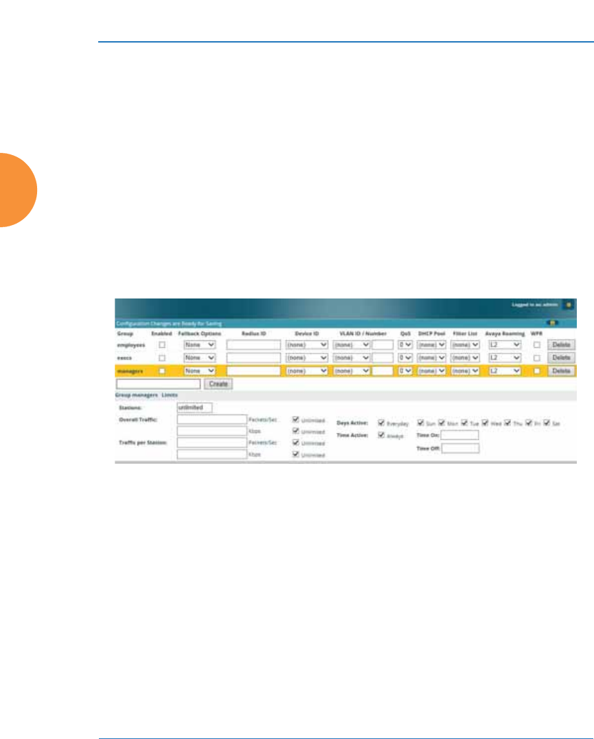
Wireless Access Point
306 Configuring the Wireless AP
See Also
External Radius
Internal Radius
SSIDs
Understanding QoS Priority on the Wireless AP
Web Page Redirect (Captive Portal) Configuration
Understanding Fast Roaming
Group Management
This window allows you to manage groups (create, edit and delete), assign usage
limits and other parameters on a per group basis, and configure the Web Page
Redirect (captive portal) functionality.
Figure 165. Group Management
Procedure for Managing Groups
1. New Group Name: To create a new group, enter a new group name next
to the Create button, then click Create. You may create up to 16 groups
(up to 8 on the XR-500 Series).
To configure and enable this group, proceed with the following steps.
2. Group: This column lists currently defined groups. When you create a
new group, the group name appears in this list. Click on any group to
select it, and then proceed to modify it as desired.

Wireless Access Point
Configuring the Wireless AP 307
3. Enabled: Check this box to enable this group or leave it blank to disable
it. When a group is disabled, users that are members of the group will
behave as if the group did not exist. In other words, the options
configured for the SSID will apply to the users, rather than the options
configured for the group.
4. Fallback: Network Assurance checks network connectivity for the AP.
When Network Assurance detects a failure, perhaps due to a bad link or
WDS failure, if Fallback is set to Disable the AP will automatically
disable users in this group. This will disassociate current clients, and
prevent them from re-associating. Since the AP’s network connectivity
has failed, this gives clients a chance to connect to other, operational parts
of the wireless network. See Step a on page 243 for more information on
Network Assurance.
5. Radius ID: Enter a unique Radius ID for the group, to be used on an
external Radius server. When adding a user account to the external
server, this Radius ID value should be entered for the user. When the user
is authenticated, Radius sends this value to the AP. This tells the AP that
the user is a member of the group having this Radius ID.
6. Device ID: You may select a device type from this drop-down list, for
example, Notebook, phone, iPhone, or Android. This allows you to
apply the group settings only if a station authenticates as a user that is a
member of the group and the station’s device type matches Device ID.
Select none if you do not want to consider the device type. If you have a
Radius ID you should not enter a Device ID.
7. VLAN ID: (Optional) From the pull-down list, select a VLAN or VLAN
Pool for this user’s traffic to use (see “VLANs” on page 213 and “VLAN
Pools” on page 215). This user group’s VLAN settings supersede
Dynamic VLAN settings (which are passed to the AP by the Radius
server). To avoid confusion, we recommend that you avoid specifying the
VLAN for a user in two places.
8. QoS Priority: (Optional) Select a value in this field for QoS (Quality of
Service) priority filtering. The QoS value must be one of the following:

Wireless Access Point
308 Configuring the Wireless AP
•0 — The lowest QoS priority setting, where QoS makes its best effort
at filtering and prioritizing data, video and voice traffic without
compromising the performance of the network. Use this setting in
environments where traffic prioritization is not a concern.
•1 — Medium; QoS prioritization is aggregated across all traffic types.
•2 — High, normally used to give priority to video traffic.
•3 — The highest QoS priority setting, normally used to give priority to
voice traffic.
The QoS setting you define here will prioritize wireless traffic for this
group versus other traffic, as described in “Understanding QoS Priority
on the Wireless AP” on page 271. The default value for this field is 2.
9. DHCP Pool: (Optional) To associate an internal DHCP pool to this group,
select it from the pull--down list. Only one pool may be assigned. An
internal DHCP pool must be created before it can be assigned. To create a
DHCP pool, go to “DHCP Server” on page 200.
10. Filter List: (Optional) If you wish to apply a set of filters to this user
group’s traffic, select the desired Filter List. See “Filters” on page 391.
11. Xirrus Roaming: (Optional) For this group, select roaming behavior.
Select L2&L3 to enable fast roaming between IAPs or APs at Layer 2 and
Layer 3. If you select L2, then roaming uses Layer 2 only. You may only
select fast roaming at Layers 2 and 3 if this has been selected in Global
Settings. You may select Off to disable fast roaming. See “Understanding
Fast Roaming” on page 312.
12. Web Page Redirect (WPR): (Optional) Check this box if you wish to
enable the Web Page Redirect (captive portal) functionality. This will
open a Web Page Redirect details section in the window, where your
WPR parameters may be entered. This feature may be used to display a
splash screen when a user first associates to the wireless network. After
that, it can (optionally) redirect the user to an alternate URL. See “Web
Page Redirect (Captive Portal) Configuration” on page 287 for details of
WPR configuration. Note that the Group Management window only
allows you to set up an Internal Splash page and a Landing Page URL.

Wireless Access Point
Configuring the Wireless AP 309
The authentication options that are offered on the SSID Management
page are not offered here. Since the group membership of a user is
provided to the AP by a Radius server, this means the user has already
been authenticated.
You may create a WPR Whitelist on a per-group basis if you wish. See
“Whitelist Configuration for Web Page Redirect” on page 293 for details
of WPR Whitelist usage and configuration.
Group Limits
The Limits section allows you to limit the traffic or connection times allowed for
this user group. Note that the IAPs — Global Settings window and the SSID
management windows also have options to limit the number of stations, limit
traffic, and/or limit connection times. If limits are set in more than one place, all
limits will be enforced:
z
As soon as any station limit is reached, no new stations can associate until
some other station has terminated its association.
z
As soon as any traffic limit is reached, it is enforced.
z
If any connection date/time restriction applies, it is enforced.
You can picture this as a logical AND of all restrictions. For example, suppose that
a station’s SSID is available Monday - Friday between 8:00am and 5:00pm, and
the User Group is available Monday, Tuesday, Wednesday between 6:00am and
8:00pm, then the station will be allowed on MWF between 8:00am and 5:00pm.
To eliminate confusion, we recommend that you configure one set of limits or the
other, but not both.
13. Stations: Enter the maximum number of stations allowed on this group.
The default is 1536.
14. Overall Traffic: Check the Unlimited checkbox if you do not want to
place a restriction on the traffic for this group, or enter a value in the
Packets/Sec field and make sure that the Unlimited box is unchecked to
force a traffic restriction.

Wireless Access Point
310 Configuring the Wireless AP
15. Traffic per Station: Check the Unlimited checkbox if you do not want to
place a restriction on the traffic per station for this group, or enter a value
in the Packets/Sec or Kbps field and make sure that the Unlimited box is
unchecked to force a traffic restriction.
16. Days Active: Choose Everyday if you want this group to be active every
day of the week, or select only the specific days that you want this group
to be active. Days that are not checked are considered to be the inactive
days.
17. Time Active: Choose Always if you want this group active without
interruption, or enter values in the Time On and Time Off fields to limit
the time that group members may associate.
18. To delete an entry, click its Delete button.
19. Click the Save button if you wish to make your changes permanent.
See Also
DHCP Server
External Radius
Internal Radius
Security Planning
SSIDs
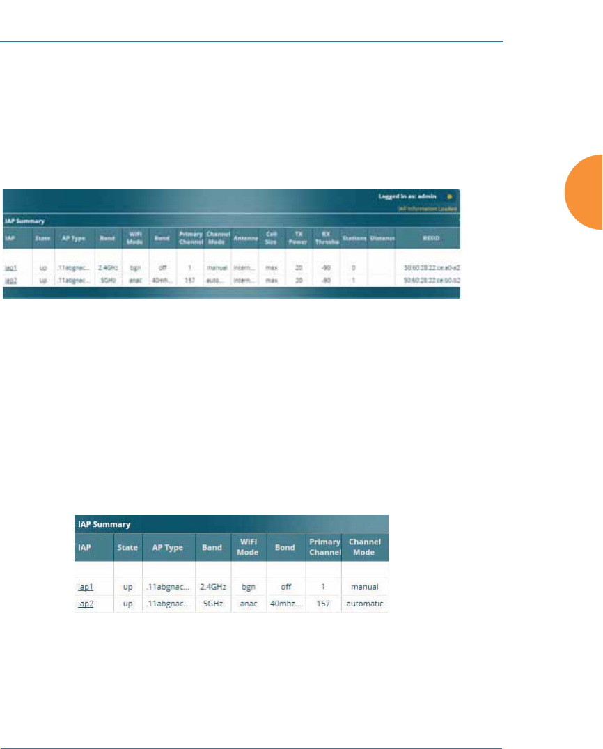
Wireless Access Point
Configuring the Wireless AP 311
IAPs
This status-only window summarizes the status of the Integrated Access Points.
For each IAP, it shows whether it is up or down, the channel and wireless mode,
the antenna that it is currently using, its cell size and transmit and receive power,
how many users (stations) are currently associated to it, whether a WDS link
distance has been set for it, and its BSSID (MAC address).
Figure 166. IAPs
The Channel Mode column displays some status information that is not found
elsewhere: the source of a channel setting. (Figure 167) If you set a channel
manually (via IAP Settings), it will be listed as manual. If an autochannel
operation changed a channel, then it is labeled as auto. If the channel is set to the
current factory default setting, the source will be default. This column also shows
whether the channel selection is locked, or whether the IAP was automatically
switched to this channel because the AP detected the signature of radar in
operation on a conflicting channel (see also, Step 8 on page 321).
Figure 167. Source of Channel Setting
There are no configuration options in this window, but if you are experiencing
problems or simply reviewing the IAP assignments, you may print this window
for your records. Click any IAP name to open the associated configuration page.

Wireless Access Point
312 Configuring the Wireless AP
APs have a fast roaming feature, allowing them to maintain sessions for
applications such as voice, even while users cross boundaries between APs. Fast
roaming is set up in the Global Settings window and is discussed in:
z
“Understanding Fast Roaming” on page 312
IAPs are configured using the following windows:
z
“IAP Settings” on page 313
z
“Global Settings” on page 319
z
“Global Settings .11an” on page 335
z
“Global Settings .11bgn” on page 341
z
“Global Settings .11n” on page 347
z
“Global Settings .11u” on page 352
z
“Global Settings .11ac” on page 350
z
“Advanced RF Settings” on page 358
z
“Hotspot 2.0” on page 367
z
“NAI Realms” on page 370
z
“NAI EAP” on page 371
z
“Intrusion Detection” on page 373
z
“LED Settings” on page 380
z
“DSCP Mappings” on page 381
“Roaming Assist” on page 382See Also
IAP Statistics Summary
Understanding Fast Roaming
To maintain sessions for real-time data traffic, such as voice and video, users must
be able to maintain the same IP address through the entire session. With
traditional networks, if a user crosses VLAN or subnet boundaries (i.e., roaming
between domains), a new IP address must be obtained.
Mobile wireless users are likely to cross multiple roaming domains during a
single session (especially wireless users of VoIP phones). Layer 3 roaming allows
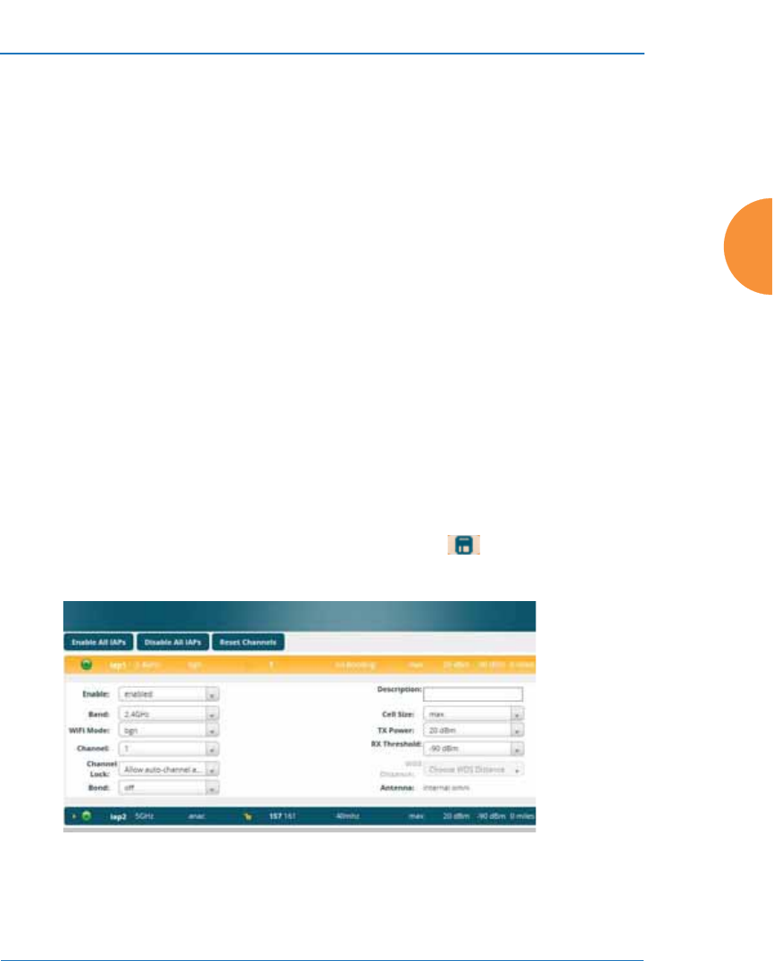
Wireless Access Point
Configuring the Wireless AP 313
a user to maintain the same IP address through an entire real-time data session.
The user may be associated to any of the VLANs defined on the AP. The Layer 3
session is maintained by establishing a tunnel back to the originating AP. You
should decide whether or not to use Layer 3 roaming based on your wired
network design. Layer 3 roaming incurs extra overhead and may result in
additional traffic delays. You may configure one SSID for Layer 3 fast roaming
with up to 25 APs.
Fast Roaming is configured on two pages. To enable the fast roaming options that
you want to make available on your AP, see Step 29 to Step 31 in “Global
Settings” on page 319. To choose which of the enabled options are used by an
SSID or Group, see “Procedure for Managing SSIDs” on page 278 (Step 14) or
“Procedure for Managing Groups” on page 306.
IAP Settings
This window allows you to enable/disable IAPs, define the wireless mode for
each IAP, specify the channel and bond width and the cell size for each IAP, lock
the channel selection, establish transmit/receive parameters, and reset channels.
Buttons at the top of the list allow you to Reset Channels, Enable All IAPs, or
Disable All IAPs. When finished, click the Save button if you wish to make
your changes permanent.
Figure 168. IAP Settings

Wireless Access Point
314 Configuring the Wireless AP
You may also access this window by clicking on the AP image at the lower left of
the WMI window — click the Xirrus logo in the center of the AP. See “User
Interface” on page 89.
Procedure for Auto Configuring IAPs
You can auto-configure channel and cell size of radios by clicking on the Auto
Configure buttons on the appropriate WMI page as shown below (auto
configuration only applies to enabled radios):
z
For all radios, go to “Advanced RF Settings” on page 358.
z
For all 802.11a settings, go to “Global Settings .11an” on page 335.
z
For all 802.11bg settings, go to “Global Settings .11bgn” on page 341.
z
For all 802.11n settings, go to “Global Settings .11n” on page 347.
z
For all 802.11ac settings, go to “Global Settings .11ac” on page 350.
Procedure for Manually Configuring IAPs
1. The row for each IAP summarizes its settings. Click to expand it and
display the settings. Click again to collapse the entry.
2. In the Enable field select enabled, or select disabled if you want to turn
off the IAP. The state of the channel is displayed with a green dot if
enabled, and a red dot if disabled.
3. In the Band field, select the wireless band for this IAP from the choices
available in the pull-down menu, either 2.4GHz or 5 GHz. Choosing the
5GHz band will automatically select an adjacent channel for bonding. If
the band displayed is auto, the Band is about to be changed based on a
new Channel selection that you made that requires the change.
#For XR-520 Series APs only:
—iap1 may be set to either band or to monitor (also see the Timeshare
option in “RF Monitor” on page 359).
—iap2 is permanently set to 5 GHz.

Wireless Access Point
Configuring the Wireless AP 315
One of the IAPs must be set to monitor mode if you wish to support
Spectrum Analyzer, Radio Assurance (loopback testing), and Intrusion
Detection features. Monitoring has a Timeshare mode option, which is
especially useful for small APs with two IAPs allowing one IAP to be
shared between monitoring the airwaves for problems and providing
services to stations. See RF Monitor Mode in “Advanced RF Settings” on
page 358 to set this option.
4. In the WiFi Mode field, select the IEEE 802.11 wireless mode (or
combination) that you want to allow on this IAP. The drop-down list will
only display the appropriate choices for the selected Band. For example,
the 5 GHz band allows you to select ac-only, anac, an, a-only, or n-only,
while 2.4GHz includes 802.11b and 802.11g choices. When you select a
WiFi Mode for any IAP, your selection in the Channel column will be
checked to ensure that it is a valid choice for that WiFi Mode.
By selecting appropriate WiFi Modes for the radios on your APs, you can
greatly improve wireless network performance. For example, if you have
802.11n and 802.11ac stations using the same IAP, throughput on that
radio is reduced greatly for the 802.11ac stations. By supporting 802.11n
stations only on selected radios in your network, the rest of your 802.11ac
IAPs will have greatly improved performance. Take care to ensure that
your network provides adequate coverage for the types of stations that
you need to support.
5. In the Channel field, select the channel you want this IAP to use from the
channels available in the pull-down list. The list shows the channels
available for the IAP selected (depending on which band the IAP is
using). Channels that are shown in gray are unavailable. They are either
already in use, or not offered for the selected Band.
The channels that are available for assignment to IAPs will differ,
depending on the country of operation. If Country is set to United States
in the Global Settings window, then 21 channels are available to 802.11an
radios.

Wireless Access Point
316 Configuring the Wireless AP
6. Set Channel Lock to Block auto-channel assignment if you want to lock
in your channel selection so that an autochannel operation (see Advanced
RF Settings) can’t change it. A locked padlock will be displayed for
the IAP.
7. The Bond field works together with the Channel selected above. (For
802.11n IAPs, it also obeys the bonding options selected on the Global
Settings .11n page.) Also see the discussion in “80 MHz and 160 MHz
Channel Widths (Bonding)” on page 48. Bonding is available on all APs,
including two-radio models. For 802.11n, two 20MHz channels may be
bonded to create one 40 MHz channel with double the data rate. 802.11ac
offers an additional option to bond four 20MHz channels to create one
80MHz channel with four times the data rate.
•Channel number — If a channel number appears, then this channel is
already bonded to the listed channel.
•Off — Do not bond his channel to another channel.
•40 MHz — Bond this channel to an adjacent channel. The bonded
channel is selected automatically by the AP based on the
Channel (Step 5). The choice of banded channel is static — fixed once
the selection is made.
•80 MHz — Bond this channel to three adjacent channels. The bonded
channels are selected automatically by the AP based on the
Channel (Step 5). The choice of bonded channels is static — fixed once
the selection is made.
The top line for the IAP will show the channels that have been assigned
based on the width of the bond.
#As mandated by FCC/IC law, APs continually scan for signatures of radar.
If such a signature is detected, the AP will switch operation from conflicting
channels to new ones. The AP will switch back to the original channel after
30 minutes if the channel is clear. If a radio was turned off because there were
no available channels not affected by radar, the AP will now bring that radio
back up after 30 minutes if that channel is clear. The 30 minute time frame
complies with FCC/IC regulations.

Wireless Access Point
Configuring the Wireless AP 317
8. In the Cell Size field, select auto to allow the optimal cell size to be
automatically computed (see also, “RF Power and Sensitivity” on
page 361). To set the cell size yourself, choose either small, medium,
large, or max to use the desired pre-configured cell size. Alternatively,
you can set the wireless cell size manually by specifying the transmit and
receive power — in dB — in the Tx Power (transmit) and Rx Threshold
(receive) fields. If you set manual values, the Cell Size field will display
the value manual after the page is refreshed.
The default for Cell Size is max. If you select a value other than auto, the
cell size will not be affected by cell size auto configuration. Note that ultra
low power Tx dBm settings are possible. Values from -15dB to 5dB are
provided specifically to help in high density 2.4 GHz environments.
When other APs are within listening range of this one, setting cell sizes to
Auto allows the AP to change cell sizes so that coverage between cells is
maintained. Each cell size is optimized to limit interference between
sectors of other APs on the same channel. This eliminates the need for a
network administrator to manually tune the size of each cell when
installing multiple APs. In the event that an AP or a radio goes offline, an
adjacent AP can increase its cell size to help compensate.
The number of users and their applications are major drivers of
bandwidth requirements. The network architect must account for the
number of users within the AP’s cell diameter. In a large office, or if
multiple APs are in use, you may choose Small cells to achieve a higher
data rate, since walls and other objects will not define the cells naturally.
For additional information about cell sizes, go to “Coverage and Capacity
Planning” on page 34.
9. If you are using WDS to provide backhaul over an extended distance, use
WDS Distance (Miles) to prevent timeout problems associated with long
transmission times. Set the approximate distance in miles between this
IAP and the connected AP in this column. This increases the wait time for
frame transmission accordingly.

Wireless Access Point
318 Configuring the Wireless AP
10. The Antenna field displays the antenna that has automatically been
selected for this IAP.
11. If desired, enter a description for this IAP in the Description field.
12. You may reset all of the enabled IAPs by clicking the Reset Channels
button at the top of the list. A message will inform you that all enabled
radios have been taken down and brought back up.
13. Buttons at the top of the list allow you to Enable All IAPs or Disable All
IAPs.
14. Click the Save button if you wish to make your changes permanent.
See Also
Coverage and Capacity Planning
Global Settings
Global Settings .11an
Global Settings .11bgn
Global Settings .11n
Global Settings .11ac
Advanced RF Settings
IAPs
IAP Statistics Summary
LED Settings
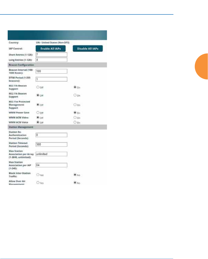
Wireless Access Point
Configuring the Wireless AP 319
Global Settings
Figure 169. Global Settings (IAPs)
This window allows you to establish global IAP settings. Global IAP settings
include enabling or disabling all IAPs (regardless of their operating mode), and
changing settings for beacons, station management, and advanced traffic
optimization — including multicast processing, load balancing, and roaming.
Changes you make on this page are applied to all IAPs, without exception.

Wireless Access Point
320 Configuring the Wireless AP
Procedure for Configuring Global IAP Settings
1. Country: This is a display-only value. Once a country has been set, it may
not be changed.
The channels that are available for assignment to IAPs will differ,
depending on the country of operation. If Country is set to United States,
then 2 channels are available for 802.11a/n.
If no country is displayed, the channel set defaults to channels and power
levels that are legal worldwide — this set only includes the lower eight
5 GHz channels.
2. IAP Control: Click on the Enable All IAPs button to enable all IAPs for
this AP, or click on the Disable All IAPs button to disable all IAPs.
3. Short Retries: This sets the maximum number of transmission attempts
for a frame, the length of which is less than or equal to the RTS Threshold,
before a failure condition is indicated. The default value is 7. Enter a new
value (1 to 128) in the Short Retry Limit field if you want to increase or
decrease this attribute.
4. Long Retries: This sets the maximum number of transmission attempts
for a frame, the length of which is greater than the RTS Threshold, before
a failure condition is indicated. The default value is 4. Enter a new value
(1 to 128) in the Long Retry Limit field if you want to increase or decrease
this attribute.
5. Wi-Fi Alliance Mode: Set this On if you need AP behavior to conform
completely to Wi-Fi Alliance standards. This mode is normally set to Off.

Wireless Access Point
Configuring the Wireless AP 321
Beacon Configuration
6. Beacon Interval: When the AP sends a beacon, it includes with it a
beacon interval, which specifies the period of time before it will send the
beacon again. Enter the desired value in the Beacon Interval field,
between 20 and 1000 Kusecs. A Kusec is 1000 microseconds =
1 millisecond. The value you enter here is applied to all IAPs.
7. DTIM Period: A Delivery Traffic Indication Message (DTIM) is a signal
sent as part of a beacon by the AP to a client device in sleep mode,
alerting the device to broadcast traffic awaiting delivery. The DTIM
Period is a multiple of the Beacon Interval, and it determines how often
DTIMs are sent out. By default, the DTIM period is 1, which means that it
is the same as the beacon interval. Enter the desired multiple, between 1
and 255. The value you enter here is applied to all IAPs.
8. 802.11h Beacon Support: This option enables beacons on all of the AP’s
radios to conform to 802.11h requirements, supporting dynamic
frequency selection (DFS) and transmit power control (TPC) to satisfy
regulatory requirements for operation in Europe.
9. 802.11k Beacon Support: 802.11k offers faster and more efficient roaming.
When enabled, each beacon lists the channels that nearby APs offer. This
supports improved channel scanning, resulting in faster roam times and
increased battery life due to shorter scan times since the station knows
where to look for nearby APs. The AP will also respond to requests from
stations for an 802.11K Neighbor Report with additional information
about nearby APs. This setting is enabled by default.
10. 802.11w Protected Management Support: This option protects the
wireless network infrastructure against spoofing by outside APs.
Authenticate, De-authenticate, Associate, and Dis-associate management
frames are sent in a secured manner when this option is enabled.

Wireless Access Point
322 Configuring the Wireless AP
11. WMM Power Save: Click On to enable Wireless Multimedia Power Save
support, as defined in IEEE802.11e. This option saves power and
increases battery life by allowing the client device to doze between
packets to save power, while the AP buffers downlink frames. The default
setting is On.
12. WMM ACM Video: Click On to enable Wireless Multimedia Admission
Control for video traffic. When admission control for video is enabled, the
AP evaluates a video request from a client device against the network
load and channel conditions. If the network is not congested, it accepts
the request and grants the client the medium time for its traffic stream.
Otherwise, it rejects the request. This enables the AP to maintain QoS
when the WLAN becomes congested after a connection has already been
established. Some clients contain sufficient intelligence to decide to either
delay the traffic stream, associate with a different AP, or establish a best-
effort traffic stream outside the operation of WMM-Admission Control.
The default setting is Off. Note that the QoS priority of traffic queues is
voice, video, best effort, background—this gives the highest priority to
voice transmissions.
13. WMM ACM Voice: Click On to enable Wireless Multimedia Admission
Control for voice calls. As for WMM ACM Video above, when admission
control for voice is enabled, the AP evaluates a voice request from a client
device against the network load and channel conditions. If the network is
not congested, it accepts the request and grants the client the medium
time for its call. Otherwise, it rejects the request. Some clients contain
sufficient intelligence to decide to either delay the traffic stream, associate
with a different AP, or establish a best-effort traffic stream outside the
operation of WMM-Admission Control. The default setting is Off.
Station Management
14. Station Re-Authentication Period: This specifies an interval (in seconds)
for station reauthentications. This is the minimum time period between
station authentication attempts, enforced by the AP. This feature is part of
the Xirrus Advanced RF Security Manager (RSM).

Wireless Access Point
Configuring the Wireless AP 323
15. Station Timeout Period: Specify a time (in seconds) in this field to define
the timeout period for station associations.
16. Max Station Association per Access Point: This option allows you to
define how many station associations are allowed per AP, or enter
unlimited. Note that the Max Station Association per IAP limit (below)
may not be exceeded, so entering unlimited, in practice, will stop at the
per-IAP limit.
17. Max Station Association per IAP: This defines how many station
associations are allowed per IAP. Note that the SSIDs > SSID
Management window also has a station limit option — Station Limit, and
the windows for Global Settings .11an and Global Settings .11bgn also
have Max Stations settings. If multiple station limits are set, all will be
enforced. As soon as any limit is reached, no new stations can associate
until some other station has terminated its association.
18. Block Inter-Station Traffic: This option allows you to block or allow
traffic between wireless clients that are associated to the AP. Choose
either Yes (to block traffic) or No (to allow traffic).
19. Allow Over Air Management: Choose Yes to enable management of the
AP via the IAPs, or choose No (recommended) to disable this feature.
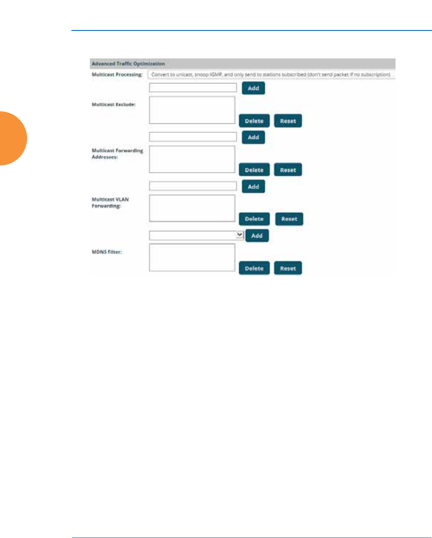
Wireless Access Point
324 Configuring the Wireless AP
Advanced Traffic Optimization
Figure 170. Multicast Processing
20. Multicast Processing: This sets how multicast traffic is handled.
Multicast traffic can be received by a number of subscribing stations at
the same time, thus saving a great deal of bandwidth. In some of the
options below, the AP uses IGMP snooping to determine the stations that
are subscribed to the multicast traffic. IGMP (Internet Group
Management Protocol) is used to establish and manage the membership
of multicast groups.
Multicast handling options are only applicable to traffic transmitted from
the AP to wireless stations. Select one of the following options:
•Send multicasts unmodified. This is useful when multicast is not
needed because no video or audio streaming is required or when it is
used only for discovering services in the network. Some situations
where you might use this option are:

Wireless Access Point
Configuring the Wireless AP 325
•for compatibility with ordinary operation, i.e., there is no
optimization or modification of multicast traffic.
•if you have an application where many subscribers need to see
the multicast—a large enough number that it would be less
efficient to convert to unicast and better just to send out multicast
even though it must be sent out at the speed of the slowest
connected station.
An example of a situation that might benefit from the use of this
mode is ghosting all the laptops in a classroom using multicast. One
multicast stream at, say, 6 Mbps is probably more efficient than thirty
unicast streams.
The next three options convert multicast to unicast. Packets are sent
directly to the stations at the best possible data rates. This approach
significantly improves the quality of the voice and video multicast
streams.
•Convert to unicast and send unicast packets to all stations. This
may be useful in link-local multicast situations.
•Convert to unicast, snoop IGMP, and only send to stations
subscribed (send as multicast if no subscription). This option is
useful when you need to stream voice or video multicast traffic to all
stations, but some stations are capable of subscribing to multicast
groups while other stations are not. The stations that do not subscribe
will not benefit from conversion to unicast; their video or voice
quality may be compromised.
•Convert to unicast, snoop IGMP, and only send to stations
subscribed (don't send packet if no subscription). This option is
useful in well controlled environments when you need to stream
voice or video multicast traffic only to stations that are capable of
subscribing to multicast groups and there is no need for the rest of the
stations to receive the data stream.
21. Multicast Exclude: This is a list of multicast IP addresses that will not be
subject to multicast-to-unicast conversion. This list is useful on networks
where applications such as those using multicast Domain Name System

Wireless Access Point
326 Configuring the Wireless AP
(mDNS) are in use. For example, Apple Bonjour finds local network
devices such as printers or other computers using mDNS. By default, the
list contains the IPv4 multicast address for Apple Bonjour mDNS:
224.0.0.251. For an additional discussion of optimizing Apple Bonjour
handling, see the Bonjour Director Application Note in the Xirrus Resource
Center.
To add a new IP address to the list, type it in the top field and click the
Add button to its right. You may only enter IP addresses—host names are
not allowed. This is because mDNS is a link local multicast address, and
does not require IGMP to the gateway.
To remove an entry, select it in the list and click Delete. To remove all
entries from the list, click Reset.
22. Multicast Forwarding
Multicast Forwarding is a Xirrus feature that forwards selected multicast
traffic between wired VLANs and wireless SSIDs. For example, Apple
devices use mDNS to advertise and find services, using local network
multicasts that are not routed. This creates an issue when you are using
Apple devices on the Wireless LAN, and have other devices that provide
services connected on the wired infrastructure in a different VLAN, for
example, printers and AppleTV devices. One way to address this issue is
to set up multicast forwarding between the wireless SSID and the wired
VLAN. This requires the wired VLAN to be trunked to the AP. Once
configured correctly, mDNS traffic will be forwarded from the specified
wireless network(s) to the specified wired VLANs and vice-versa, subject
to any mDNS service filtering defined (Step 24).
Use multicast forwarding together with multicast VLAN forwarding
(Step 23) and mDNS filtering (Step 24) to make services available across
VLANs as follows:
•In Multicast Forwarding Addresses, enter a list of multicast
addresses that you want forwarded, for example, 224.0.0.251 (the
multicast address for Bonjour).

Wireless Access Point
Configuring the Wireless AP 327
•In Multicast VLAN Forwarding, enter a list of VLANs that
participate in the multicast forwarding.
•In MDNS Filter, specify the mDNS service types that are allowed to
be forwarded.
•If you leave this field blank, then there is no filter, and mDNS
packets for all service types are passed.
•If you enter service types, then this acts as an allow filter, and
mDNS packets are passed only for the listed service types.
Note that mDNS filtering may be used to filter the mDNS packet
types that are forwarded within the same VLAN. Also, in conjunction
with multicast forwarding, it may be used to filter the mDNS packet
types that are forwarded across configured VLANs.
After you have entered these settings, when multicast packets arrive from
the wired network from one of the Multicast Forwarding Addresses on
any VLAN specified in Multicast VLAN Forwarding, they are forwarded
to the corresponding wireless SSID for that VLAN.
Multicast packets coming in from the wireless network on an SSID tied to
one of the specified VLANs and matching one of the Multicast
Forwarding Addresses are forwarded to the specified VLANs on the
wired network.
No modifications are made to the forwarded packets – they are just
forwarded between specified VLANs and associated SSIDs.
To specify Multicast Forwarding Addresses: enter each IP address in the
top field and click the Add button to its right. You may only enter IPv4
#Xirrus strongly recommends the use of MDNS Filters (Step 24) when using
multicast forwarding. Only allow required services to be forwarded.
Carefully monitor results, as forwarding may flood your network with
multicast traffic. Experience has shown Bonjour devices to be very chatty.
Also note that since this is link local multicast traffic, it will be sent to every
wired port in the VLAN, as IGMP snooping does not work with link local
multicast addresses.

Wireless Access Point
328 Configuring the Wireless AP
multicast addresses - host names are not allowed. To remove an entry,
select it in the list and click Delete. To remove all entries from the list,
click Reset.
23. Multicast VLAN Forwarding: This is a list of VLANs that participate in
the multicast forwarding. Please see the description of multicast
forwarding in Step 22 above.
Multicast VLAN Forwarding operates as follows:
•If you leave this field blank, then there is no filter, and Multicast
Forwarding traffic is passed across all VLANs.
•If you enter VLANs, then this acts as an allow filter, and Multicast
Forwarding traffic is passed only to the listed VLANS.
To add a new VLAN to the list, enter its number or name in the top field
and click the Add button to its right. You may enter multiple VLANs at
once, separated by a space. To remove an entry, select it in the list and
click Delete. To remove all entries from the list, click Reset.
These VLANs must be trunked to the AP from the LAN switch, and be
defined on the AP. See “VLAN Management” on page 216 and “SSID
Management” on page 277.
#The VLANs you enter must be explicitly defined (see “VLANs” on
page 213) in order to participate in multicast forwarding. In fact, the AP
discards packets from undefined VLANs.

Wireless Access Point
Configuring the Wireless AP 329
24. MDNS Filter: There are many different types of services that may be
specified in multicast query and response packets. The mDNS filters let
you restrict forwarding, so that multicast packets are forwarded only for
the services that you explicitly specify. This list may be used to restrict the
amount of Apple Bonjour multicast traffic forwarding. For example, you
may restrict forwarding to just AppleTV and printing services. Please see
the description of multicast forwarding in Step 22 above.
The MDNS Filter operates as follows:
•If you leave this field blank, then there is no filter, and mDNS
packets for all service types are passed.
•If you enter service types, then this acts as an allow filter, and
mDNS packets are passed only for the listed service types.
To add an mDNS packet type to the list of packets that may be forwarded,
select it from the drop-down list in the top field and click the Add button
to its right. The drop-down list offers packet types such as AirTunes,
#Note that Multicast Forwarding and mDNS Filtering capabilities also work
if both devices are wireless. For example, let’s say that AppleTV is using
wireless to connect to an SSID that is associated with VLAN 56, and the
wireless client is on an SSID that is associated with VLAN 58. Normally the
wireless client would not be able to use Bonjour to discover the AppleTV
because they are on separate VLANs. But if you add 224.0.0.251 to the
Multicast Forwarding Addresses, then add VLANs 56 and 58 to the
Multicast VLAN Forwarding list, then the wireless client will be able to
discover the AppleTV. In this same scenario you could add AppleTV to the
MDNS Filter list so that only MDNS packets for the AppleTV service type
would be forwarded between VLANs 56 and 58.
Note that all the VLANs that you add to this list do not have to be associated
with SSIDs. As an example, say that AppleTV is on the wired network on
VLAN 56, while the wireless device is connected to an SSID that is
associated to VLAN 58. In this case, VLAN 56 and 58 need to be defined on
the AP but only VLAN 58 needs to be associated to a SSID.
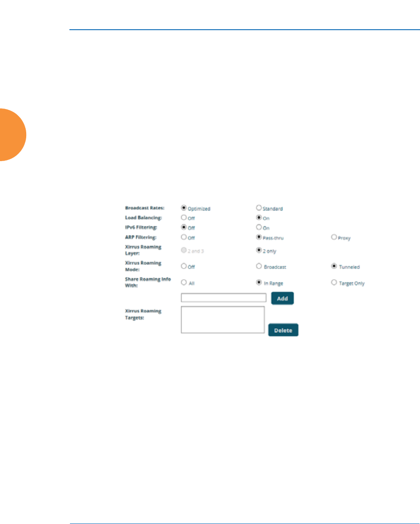
Wireless Access Point
330 Configuring the Wireless AP
Apple-TV, iChat, iPhoto, iTunes, iTunes-Home-Sharing, Internet-
Printing, Mobile-Device-Sync, and Secure-Telnet.
For example, to allow mirroring of an iPad on an Apple-TV, select Apple-
TV.
You may define your own type if you do not see the service you want in
the drop-down list. Simply enter the mDNS service name that you would
like to allow through. Custom mDNS packet types must be prefixed with
an underscore, e.g., _airvideoserver.
To remove an entry, select it in the list and click Delete. To remove all
entries from the list, click Reset.
Figure 171. Additional Optimization Settings
25. Broadcast Rates: This changes the rates of broadcast traffic sent by the AP
(including beacons). When set to Optimized, each broadcast or multicast
packet that is transmitted on each radio is sent at the lowest transmit rate
used by any client associated to that radio at that time. This results in
each IAP broadcasting at the highest AP TX data rate that can be heard by
all associated stations, improving system performance. The rate is
determined dynamically to ensure the best broadcast/multicast
performance possible. The benefit is dramatic. Consider a properly

Wireless Access Point
Configuring the Wireless AP 331
designed network (having -70db or better everywhere), where virtually
every client should have a 54Mbps connection. In this case, broadcasts
and multicasts will all go out at 54Mbps vs. the standard rate. Thus, with
broadcast rate optimization on, broadcasts and multicasts use between
2% and 10% of the bandwidth that they would in Standard mode.
When set to Standard (the default), broadcasts are sent out at the lowest
basic rate only — 6 Mbps for 5GHz clients, or 1 Mbps for 2.4GHz clients.
The option you select here is applied to all IAPs.
26. Load Balancing (ACExpress™): Wi-Fi is a shared medium and only one
device can transmit data at any time. Faster devices supporting 802.11ac
standards have to wait until the slower devices finish transmitting data.
This brings down the overall throughput of the network. For example, an
802.11n client operates more than four times slower than an 802.11ac
client, and thus will take four times more air time to communicate a given
amount of data. This starves the available bandwidth from faster clients,
reducing performance significantly. Xirrus solves this issue with
ACExpress that automatically separates devices onto different IAPs by
their speeds and capability.
ACExpress identifies station capabilities based on fingerprinting and
automatically groups devices by performance. It works on all modes
(802.11a/b/g/n/ac) and bands (2.4GHz and 5GHz). This results in
improved performance for every WLAN client and optimized use of
wireless radio resources. Factors including wireless band, number of
spatial streams, 802.11ac and 802.11n capability, and signal to noise ratio
are considered.
This feature also provides automatic load balancing designed to
distribute wireless stations across multiple radios rather than having
stations associate to the closest radios with the strongest signal strength,
as they normally would. In wireless networks, the station selects the radio
to which it will associate. The AP cannot actually force load balancing,
however it can “encourage” stations to associate in a more optimal
fashion to underused radios of the most advantageous type. This option
enables or disables active load balancing between the AP IAPs.

Wireless Access Point
332 Configuring the Wireless AP
If you select On and an IAP is not the best choice for network
performance, that IAP will send an “AP Full” message in response to
Probe, Association, or Authentication requests. This deters persistent
clients from forcing their way onto overloaded IAPs.
Note that ACExpress load balancing is not used if:
•A station is re-associating—if it was already associated to this IAP, it
is allowed back on this IAP immediately. This prevents the station
from being bounced between different IAPs.
•The IAP’s Band, WiFi Mode, and Channel settings are not at their
default values. For example, if the IAP’s WiFi mode is set to 11n-only,
load balancing will not be used. See “IAP Settings” on page 313.
•If station counts (specified at the IAP, SSID, or band level) are already
exceeded.
•If a station has already been turned down a number of times when
attempting to associate, i.e., the station will eventually be allowed
onto the IAP after a number of attempts have failed.
Choose Off to disable load balancing.
27. ARP Filtering: Address Resolution Protocol finds the MAC address of a
device with a given IP address by sending out a broadcast message
requesting this information. ARP filtering allows you to reduce the
proliferation of ARP messages by restricting how they are forwarded
across the network.
You may select from the following options for handling ARP requests:
•Off: ARP filtering is disabled. ARP requests are broadcast to radios
that have stations associated to them.
•Pass-thru: The AP forwards the ARP request. It passes along only
ARP messages that target the stations that are associated to it. This is
the default value.
•Proxy: The AP replies on behalf of the stations that are associated to
it. The ARP request is not broadcast to the stations.

Wireless Access Point
Configuring the Wireless AP 333
Note that the AP has a broadcast optimization feature that is always on (it
is not configurable). Broadcast optimization restricts all broadcast packets
(not just ARP broadcasts) to only those radios that need to forward them.
For instance, if a broadcast comes in from VLAN 10, and there are no
VLAN 10 users on a radio, then that radio will not send out that
broadcast. This increases available air time for other traffic.
28. IPv6 Filtering: this setting allows blocking of IPv6 traffic which may be a
concern for IT managers. The Xirrus AP currently bridges IPv6 traffic. Set
IPv6 filtering On if you wish to prevent the forwarding of IPv6 packets
through the AP in both directions—wired network to wireless and
wireless network to wired. The default is Off.
29. Xirrus Roaming Layer: Select whether to enable roaming capabilities
between IAPs or APs at Layer 2 and 3, or at Layer 2 only. Depending on
your wired network, you may wish to allow fast roaming at Layer 3. This
may result in delayed traffic.
30. Xirrus Roaming Mode: This feature utilizes the Xirrus Roaming Protocol
(RP) ensuring fast and seamless roaming capabilities between IAPs or
APs at Layer 2 and Layer 3 (as specified in Step 31), while maintaining
security. Fast roaming eliminates long delays for re-authentication, thus
supporting time-sensitive applications such as Voice over Wi-Fi (see
“Understanding Fast Roaming” on page 312 for a discussion of this
feature). RP uses a discovery process to identify other Xirrus APs as fast
roaming targets. This process has two modes:
•Broadcast — the AP uses a broadcast technique to discover other APs
that may be targets for fast roaming.
•Tunneled — in this Layer 3 technique, fast roaming target APs must
be explicitly specified.
To enable fast roaming, choose Broadcast or Tu n n e le d , and set additional
fast roaming attributes (Step 31). To disable fast roaming, choose Off. If
you enable Fast Roaming, the following ports cannot be blocked:
•Port 22610 — reserved for Layer 2 roaming using UDP to share PMK
information between APs.

Wireless Access Point
334 Configuring the Wireless AP
•Ports 15000 to 17999 — reserved for Layer 3 roaming (tunneling
between subnets).
31. Share Roaming Info With: Three options allow your AP to share
roaming information with all APs; just with those that are within range;
or with specifically targeted APs. Choose either All, In Range or Tar get
Only, respectively.
a. Xirrus Roaming Targets: If you chose Ta rge t Onl y, use this option to
add target MAC addresses. Enter the MAC address of each target AP,
then click on Add (add as many targets as you like). To find a target’s
MAC address, open the AP Info window on the target AP and look
for IAP MAC Range, then use the starting address of this range.
To delete a target, select it from the list, then click Delete.
See Also
Coverage and Capacity Planning
Global Settings .11ac
Global Settings .11an
Global Settings .11bgn
Global Settings .11n
Advanced RF Settings
IAPs
IAP Statistics Summary
LED Settings
IAP Settings
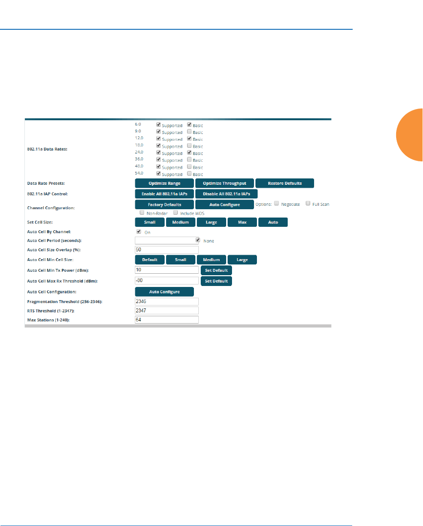
Wireless Access Point
Configuring the Wireless AP 335
Global Settings .11an
This window allows you to establish global 802.11a IAP settings. These settings
include defining which 802.11a data rates are supported, enabling or disabling all
802.11an IAPs, auto-configuration of channel allocations for all 802.11an IAPs,
and specifying the fragmentation and RTS thresholds for all 802.11an IAPs.
Figure 172. Global Settings .11an
Procedure for Configuring Global 802.11an IAP Settings
1. 802.11a Data Rates: The AP allows you to define which data rates are
supported for all 802.11an radios. Select (or deselect) data rates by
clicking in the corresponding Supported and Basic data rate check boxes.
•Basic Rate — a wireless station (client) must support this rate in order
to associate.
•Supported Rate — data rates that can be used to transmit to clients.

Wireless Access Point
336 Configuring the Wireless AP
2. Data Rate Presets: The Wireless AP can optimize your 802.11a data rates
automatically, based on range or throughput. Click Optimize Range to
optimize data rates based on range, or click Optimize Throughput to
optimize data rates based on throughput. The Restore Defaults button
will take you back to the factory default rate settings.
3. 802.11a IAP Control: Click Enable 802.11a IAPs to enable all 802.11an
IAPs for this AP, or click Disable 802.11a IAPs to disable all 802.11an
IAPs.
4. Channel Configuration: Click Auto Configure to instruct the AP to
determine the best channel allocation settings for each 802.11an IAP and
select the channel automatically, based on changes in the environment.
This is the recommended method for 802.11a channel allocation (see “RF
Spectrum Management” on page 362).
Click Factory Defaults if you wish to instruct the AP to return all IAPs to
their factory preset channels. As of release 6.3, APs no longer all use the
same factory preset values for channel assignments. Instead, if the AP has
been deployed for a while and already has data from the spectrum
analyzer and Xirrus Roaming Protocol about channel usage on
neighboring APs, it performs a quick auto channel using that information
(without doing a full RF scan) to make an intelligent choice of channel
assignments. If the AP has been rebooted and has no saved configuration
or is just being deployed for the first time, it has no prior data about its RF
environment. In this case, it will pick a set of compatible channel
assignments at random.
The following options may be selected for auto configuration:
#On the XR-500/600 and XR-1000 Series models, the Factory Defaults
button will not restore iap1 to monitor mode. You will need to restore this
setting manually. Also, you may need to set Timeshare Mode again - see
“RF Monitor” on page 359.

Wireless Access Point
Configuring the Wireless AP 337
•Non-Radar: give preference to channels that are not required to use
dynamic frequency selection (DFS) to avoid communicating in the
same frequency range as some radar (also see Step 8 on page 321).
•Negotiate: negotiate air-time with other APs before performing a full
scan.
Channels Required to Use DFS Radar Avoidance in USA
36+40 Non-radar 116
DFS required
44+48 Non-radar 132+136 DFS required
52+56 DFS required 140+144 DFS required
60+64 DFS required 149+153 Non-radar
100+104 DFS required 157+161 Non-radar
108+112 DFS required 165 Non-radar
Channels Required to Use DFS Radar Avoidance in
Europe
36+40 Non-radar 116+120* DFS required
44+48 Non-radar 124*+128* DFS required
52+56 DFS required 132+136 DFS required
60+64 DFS required 140+144 DFS required
100+104 DFS required 149+153 Non-radar
108+112 DFS required 157+161 Non-radar
* Channels 120, 124, 128 use a
10 minute Channel Availability Check
(CAC) time in Europe
165 Non-radar

Wireless Access Point
338 Configuring the Wireless AP
•Full Scan: perform a full traffic scan on all channels on all IAPs to
determine the best channel allocation.
•Include WDS: automatically assign 5GHz to WDS client links.
5. Set Cell Size: Cell Size may be set globally for all 802.11an IAPs to Auto,
Large, Medium, Small, or Max using the buttons.
For an overview of RF power and cell size settings, please see “RF Power
and Sensitivity” on page 361, “Capacity and Cell Sizes” on page 36, and
“Fine Tuning Cell Sizes” on page 37.
6. Auto Cell By Channel: By default, this feature is On, and auto cell will
adjust the cell size for a radio when nearby APs have radios on the same
channel within earshot of each other, so that the two radios minimize
interference with each other. If this option is unchecked, then auto cell
will adjust the cell size for a radio when nearby APs have radios on the
same band, even if they are using different channels (called Auto Cell by
Band, or Multichannel Auto Cell). This will result in smaller cell sizes. See
“Fine Tuning Cell Sizes” on page 37.
7. Auto Cell Period (seconds): You may set up auto-configuration to run
periodically, readjusting optimal cell sizes for the current conditions.
Enter a number of seconds to specify how often auto-configuration will
run. If you select None, then auto-configuration of cell sizing will not be
run periodically. You do not need to run Auto Cell often unless there are a
lot of changes in the environment. If the RF environment is changing
often, running Auto Cell every twenty-four hours (86400 seconds) should
be sufficient). The default value is None.
#To use the Auto Cell Size feature, any IAPs that will use Auto Cell must
have Cell Size set to auto.
For Auto Cell by Channel, it is not necessary for RF Monitor Mode to be
turned on, or for there to be a radio set to monitor mode. For Auto Cell by
Band, RF Monitor Mode must be set to Dedicated or Timeshare mode, and
there must be a radio set to monitor mode. See “RF Monitor” on page 359.

Wireless Access Point
Configuring the Wireless AP 339
8. Auto Cell Size Overlap (%): Enter the percentage of cell overlap that will
be allowed when the AP is determining automatic cell sizes. For 100%
overlap, the power is adjusted such that neighboring APs that hear each
other best will hear each other at -70dB. For 0% overlap, that number is -
90dB. The default value is 50%.
9. Auto Cell Min Cell Size: Use this setting if you wish to set the minimum
cell size that Auto Cell may assign. The values are Default, Large,
Medium, or Small.
10. Auto Cell Min Tx Power (dBm): Enter the minimum transmit power that
the AP can assign to a radio when adjusting automatic cell sizes. The
default value is 10.
11. Auto Cell Max Rx Threshold (dBm): Enter the maximum receive
threshold that the AP can assign to a radio when adjusting automatic cell
sizes. The default value is -80.
12. Auto Cell Configuration: Click this button to instruct the AP to
determine and set the best cell size for each 802.11an IAP whose Cell Size
is auto on the IAP Settings window, based on changes in the
environment. This is the recommended method for setting cell size. You
may look at the Tx and Rx values on the IAP Settings window to view the
cell size settings that were applied.
13. Fragmentation Threshold: This is the maximum size for directed data
packets transmitted over the 802.11an radio. Larger frames fragment into
several packets, their maximum size defined by the value you enter here.
Smaller fragmentation numbers can help to “squeeze” packets through in
noisy environments. Enter the desired Fragmentation Threshold value in
this field, between 256 and 2346.
14. RTS Threshold: The Request To Send (RTS) Threshold specifies the
packet size. Packets larger than the RTS threshold will use CTS/RTS prior
to transmitting the packet — useful for larger packets to help ensure the
success of their transmission. Enter a value between 1 and 2347.
15. Max Stations: This defines how many station associations are allowed
per 802.11an IAP. Note that the IAPs > Global Settings window and

Wireless Access Point
340 Configuring the Wireless AP
SSIDs — SSID Management window also have station limit settings —
Max Station Association per IAP (page 323) and Station Limit
(page 284), respectively. If multiple station limits are set, all will be
enforced. As soon as any limit is reached, no new stations can associate
until some other station has terminated its association.
See Also
Coverage and Capacity Planning
Global Settings
Global Settings .11bgn
Global Settings .11n
IAPs
IAP Statistics Summary
Advanced RF Settings
IAP Settings
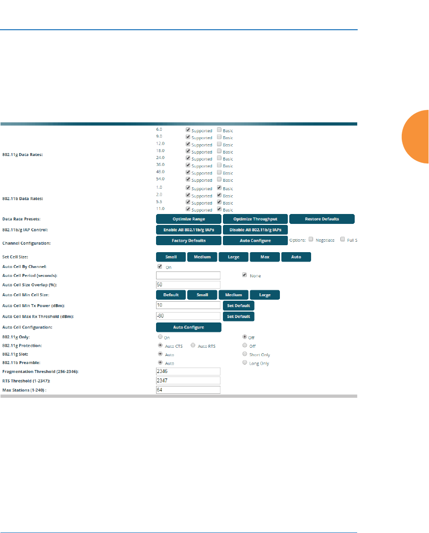
Wireless Access Point
Configuring the Wireless AP 341
Global Settings .11bgn
This window allows you to establish global 802.11b/g IAP settings. These settings
include defining which 802.11b and 802.11g data rates are supported, enabling or
disabling all 802.11b/g IAPs, auto-configuring 802.11b/g IAP channel allocations,
and specifying the fragmentation and RTS thresholds for all 802.11b/g IAPs.
Figure 173. Global Settings .11bgn

Wireless Access Point
342 Configuring the Wireless AP
Procedure for Configuring Global 802.11b/g IAP Settings
1. 802.11g Data Rates: The AP allows you to define which data rates are
supported for all 802.11g radios. Select (or deselect) 11g data rates by
clicking in the corresponding Supported and Basic data rate check boxes.
•Basic Rate — a wireless station (client) must support this rate in
order to associate.
•Supported Rate — data rates that can be used to transmit to
clients.
2. 802.11b Data Rates: This task is similar to Step 1, but these data rates
apply only to 802.11b IAPs.
3. Data Rate Presets: The Wireless AP can optimize your 802.11b/g data
rates automatically, based on range or throughput. Click Optimize Range
button to optimize data rates based on range, or click on the Optimize
Throughput to optimize data rates based on throughput. Restore
Defaults will take you back to the factory default rate settings.
4. 802.11b/g IAP Control: Click Enable All 802.11b/g IAPs to enable all
802.11b/g IAPs for this AP, or click Disable All 802.11b/g IAPs to disable
them.
5. Channel Configuration: Click Auto Configure to instruct the AP to
determine the best channel allocation settings for each 802.11b/g IAP and
select the channel automatically, based on changes in the environment.
This is the recommended method for channel allocation (see “RF
Spectrum Management” on page 362).
Click Factory Defaults if you wish to instruct the AP to return all IAPs to
their factory preset channels. As of release 6.3, APs no longer all use the
same factory preset values for channel assignments. Instead, if the AP has
been deployed for a while and already has data from the spectrum
analyzer and Xirrus Roaming Protocol about channel usage on
neighboring APs, it performs a quick auto channel using that information
(without doing a full RF scan) to make an intelligent choice of channel
assignments. If the AP has been rebooted and has no saved configuration
or is just being deployed for the first time, it has no prior data about its RF

Wireless Access Point
Configuring the Wireless AP 343
environment. In this case, it will pick a set of compatible channel
assignments at random.
The following options may be selected for auto configuration:
•Negotiate: negotiate air-time with other APs before performing a full
scan.
•Full Scan: perform a full traffic scan on all channels on all IAPs to
determine the best channel allocation.
•Non-Radar: give preference to channels without radar-detect. See
table in “Procedure for Configuring Global 802.11an IAP Settings” on
page 335.
•Include WDS: automatically assign 5GHz to WDS client links.
6. Set Cell Size/ Autoconfigure: Cell Size may be set globally for all
802.11b/g IAPs to auto, large, medium, small, or max using the drop
down menu.
For an overview of RF power and cell size settings, please see “RF Power
and Sensitivity” on page 361, “Capacity and Cell Sizes” on page 36, and
“Fine Tuning Cell Sizes” on page 37.
7. Auto Cell By Channel: By default, this feature is On, and auto cell will
adjust the cell size for a radio when nearby APs have radios on the same
channel within earshot of each other, so that the two radios minimize
interference with each other. If this option is unchecked, then auto cell
will adjust the cell size for a radio when nearby APs have radios on the
same band, even if they are using different channels (called Auto Cell by
Band, or Multichannel Auto Cell). This will result in smaller cell sizes. See
“Fine Tuning Cell Sizes” on page 37.
#On the XR-500/600 and XR-1000 Series, the Factory Defaults button will
not restore iap1 to monitor mode. You will need to restore this setting
manually. Also, you may need to set Timeshare Mode again - see “RF
Monitor” on page 359.

Wireless Access Point
344 Configuring the Wireless AP
8. Auto Cell Period (seconds): You may set up auto-configuration to run
periodically, readjusting optimal cell sizes for the current conditions.
Enter a number of seconds to specify how often auto-configuration will
run. If you select None, then auto-configuration of cell sizing will not be
run periodically. You do not need to run Auto Cell often unless there are a
lot of changes in the environment. If the RF environment is changing
often, running Auto Cell every twenty-four hours (86400 seconds) should
be sufficient). The default value is None.
9. Auto Cell Size Overlap (%): Enter the percentage of cell overlap that will
be allowed when the AP is determining automatic cell sizes. For 100%
overlap, the power is adjusted such that neighboring APs that hear each
other best will hear each other at -70dB. For 0% overlap, that number is -
90dB. The default value is 50%.
10. Auto Cell Min Cell Size: Use this setting if you wish to set the minimum
cell size that Auto Cell may assign. The values are Default, Large,
Medium, or Small.
11. Auto Cell Min Tx Power (dBm): Enter the minimum transmit power that
the AP can assign to a radio when adjusting automatic cell sizes. The
default value is 10.
12. Auto Cell Max Rx Threshold (dBm): Enter the maximum receive
threshold that the AP can assign to a radio when adjusting automatic cell
sizes. The default value is -80.
#To use the Auto Cell Size feature, any IAPs that will use Auto Cell must
have Cell Size set to auto.
For Auto Cell by Channel, it is not necessary for RF Monitor Mode to be
turned on, or for there to be a radio set to monitor mode. For Auto Cell by
Band, RF Monitor Mode must be set to Dedicated or Timeshare mode,
and there must be a radio set to monitor mode. See “RF Monitor” on
page 359.

Wireless Access Point
Configuring the Wireless AP 345
13. Auto Cell Configuration: Click Auto Configure to instruct the AP to
determine and set the best cell size for each enabled 802.11b/g IAP whose
Cell Size is auto on the IAP Settings window, based on changes in the
environment. This is the recommended method for setting cell size. You
may look at the Tx and Rx values on the IAP Settings window to view the
cell size settings that were applied.
14. 802.11g Only: Choose On to restrict use to 802.11g mode only. In this
mode, no 802.11b rates are transmitted. Stations that only support 802.11b
will not be able to associate.
15. 802.11g Protection: You should select Auto CTS or Auto RTS to provide
automatic protection for all 802.11g radios in mixed networks (802.11
b and g). You may select Off to disable this feature, but this is not
recommended. Protection allows 802.11g stations to share the IAP with
older, slower 802.11b stations. Protection avoids collisions by preventing
802.11b and 802.11g stations from transmitting simultaneously. When
Auto CTS or Auto RTS is enabled and any 802.11b station is associated to
the IAP, additional frames are sent to gain access to the wireless network.
•Auto CTS requires 802.11g stations to send a slow Clear To Send
frame that locks out other stations. Automatic protection reduces
802.11g throughput when 802.11b stations are present — Auto CTS
adds less overhead than Auto RTS. The default value is Auto CTS.
•With Auto RTS, 802.11g stations reserve the wireless media using a
Request To Send/Clear To Send cycle. This mode is useful when you
have dispersed nodes. It was originally used in 802.11b only
networks to avoid collisions from “hidden nodes” — nodes that are so
widely dispersed that they can hear the AP, but not each other.
When there are no 11b stations associated and an auto-protection mode is
enabled, the AP will not send the extra frames, thus avoiding
unnecessary overhead.
16. 802.11g Slot: Choose Auto to instruct the AP to manage the 802.11g slot
times automatically, or choose Short Only. Xirrus recommends using
Auto for this setting, especially if 802.11b devices are present.

Wireless Access Point
346 Configuring the Wireless AP
17. 802.11b Preamble: The preamble contains information that the AP and
client devices need when sending and receiving packets. All compliant
802.11b systems have to support the long preamble. A short preamble
improves the efficiency of a network's throughput when transmitting
special data, such as voice, VoIP (Voice-over IP) and streaming video.
Select Auto to instruct the AP to manage the preamble (long and short)
automatically, or choose Long Only.
18. Fragmentation Threshold: This is the maximum size for directed data
packets transmitted over the 802.11b/g IAP. Larger frames fragment into
several packets, their maximum size defined by the value you enter here.
Enter the desired Fragmentation Threshold value, between 256 and 2346.
19. RTS Threshold: The RTS (Request To Send) Threshold specifies the
packet size. Packets larger than the RTS threshold will use CTS/RTS prior
to transmitting the packet — useful for larger packets to help ensure the
success of their transmission. Enter a value between 1 and 2347.
20. Max Stations: This defines how many station associations are allowed
per 802.11bgn IAP. Note that the IAPs > Global Settings window and
SSIDs > SSID Management window also have station limit settings —
Max Station Association per IAP (page 323) and Station Limit
(page 284), respectively. If multiple station limits are set, all will be
enforced. As soon as any limit is reached, no new stations can associate
until some other station has terminated its association.
See Also
Coverage and Capacity Planning
Global Settings
Global Settings .11an
Global Settings .11n
Advanced RF Settings
LED Settings
IAP Settings
IAP Statistics Summary
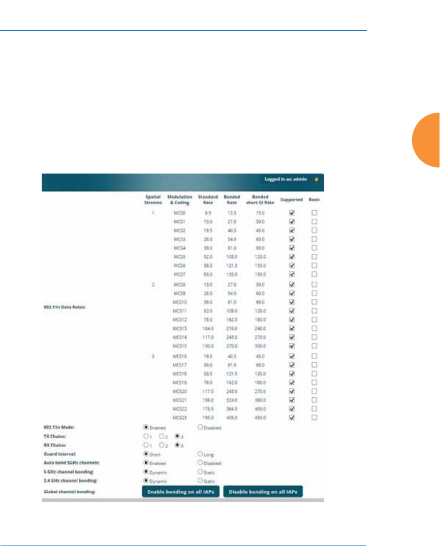
Wireless Access Point
Configuring the Wireless AP 347
Global Settings .11n
This window allows you to establish global 802.11n IAP settings. These settings
include enabling or disabling 802.11n mode for the entire AP, specifying the
number of transmit and receive chains (data stream) used for spatial
multiplexing, setting a short or standard guard interval, auto-configuring channel
bonding, and specifying whether auto-configured channel bonding will be static
or dynamic.
Before changing your settings for 802.11n, please read the discussion in “About
IEEE 802.11ac” on page 42.
Figure 174. Global Settings .11n

Wireless Access Point
348 Configuring the Wireless AP
Procedure for Configuring Global 802.11n IAP Settings
1. 802.11n Data Rates: The AP allows you to define which data rates are
supported for all 802.11n radios. Select (or deselect) 11n data rates by
clicking in the corresponding Supported and Basic data rate check boxes.
•Basic Rate — a wireless station (client) must support this rate in
order to associate.
•Supported Rate — data rates that can be used to transmit to
clients.
2. 802.11n Mode: Select Enabled to allow the AP to operate in 802.11n
mode.
If you select Disabled, then 802.11n operation is disabled on the AP.
3. TX Chains: Select the number of separate data streams transmitted by the
antennas of each IAP. The maximum number of chains is determined by
whether the AP has 2x2 or 3x3 radios. The default value is always the
maximum supported by the radio type. See “Up to Eight Simultaneous
Data Streams — Spatial Multiplexing” on page 44.
4. RX Chains: Select the number of separate data streams received by the
antennas of each IAP. This number should be greater than or equal to TX
Chains. The maximum number of chains is determined by whether the
AP has 2x2 or 3x3 radios. The default value is always the maximum
supported by the radio type. See “Up to Eight Simultaneous Data
Streams — Spatial Multiplexing” on page 44.
5. Guard interval: Select Short to increase the data transmission rate by
decreasing wait intervals in signal transmission. Select Long to use the
standard interval. The default is Short.
6. Auto bond 5 GHz channels: Select Enabled to use Channel Bonding on
5 GHz channels and automatically select the best channels for bonding.
The default is Enabled. See “80 MHz and 160 MHz Channel Widths
(Bonding)” on page 48.

Wireless Access Point
Configuring the Wireless AP 349
7. 5 GHz Channel Bonding: Select Dynamic to have auto-configuration for
bonded 5 GHz channels be automatically updated as conditions change.
For example, if there are too many clients to be supported by a bonded
channel, dynamic mode will automatically break the bonded channel into
two channels. Select Static to have the bonded channels remain the same
once they are selected. The Dynamic option is only available when Auto
bond 5 GHz channels is enabled. The default is Dynamic. See “80 MHz
and 160 MHz Channel Widths (Bonding)” on page 48.
8. 2.4 GHz Channel Bonding: Select Dynamic to have auto-configuration
for bonded 2.4 GHz channels be automatically updated as conditions
change. Select Static to have the bonded channels remain the same once
they are selected. The default is Dynamic. See “80 MHz and 160 MHz
Channel Widths (Bonding)” on page 48.
9. Global channel bonding: These buttons allow you to turn channel
bonding on or off for all IAPs in one step. The effect of using one of these
buttons will be shown if you go to the IAP Settings window and look at
the Bond column. Clicking Enable bonding on all IAPs causes all IAPs
to be bonded to their auto-bonding channel immediately, if appropriate.
For example, the IAP will not be bonded if it is set to monitor mode, and
2.4 GHz radios will not be bonded. Click Disable bonding on all IAPs to
turn off bonding on all IAPs immediately. See “80 MHz and 160 MHz
Channel Widths (Bonding)” on page 48. Settings in Step 7 and Step 8 are
independent of global channel bonding.
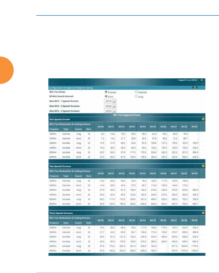
Wireless Access Point
350 Configuring the Wireless AP
Global Settings .11ac
This window allows you to establish global 802.11ac IAP settings. These settings
include enabling or disabling 802.11ac mode for the entire AP, specifying the
number of data streams used in spatial multiplexing, and setting a short or long
guard interval.
Before changing your settings for 802.11ac, please read the discussion in “About
IEEE 802.11ac” on page 42.
Figure 175. Global Settings .11ac

Wireless Access Point
Configuring the Wireless AP 351
Procedure for Configuring Global 802.11ac IAP Settings
1. 802.11ac Mode: Select Enabled to allow the AP to operate in 802.11ac
mode. If you select Disabled, then 802.11ac operation is disabled on the
AP.
2. 80 MHz Guard interval: This is the length of the interval between
transmission of symbols (the smallest unit of data transfer) when you are
using 80MHz bonded channels. (See “80 MHz and 160 MHz Channel
Widths (Bonding)” on page 48.) Select Short to increase the data
transmission rate by decreasing wait intervals in signal transmission.
Select Long to use the standard interval. The default is Short.
3. Max MCS: Select the highest Modulation and Coding Scheme level that
may be used with 1 or 2 Spatial Streams. For models with 3x3 radios,
there is also a setting for 3 Spatial Streams. This setting may be used to
limit the highest level of modulation to 64-QAM, or allow 256-QAM with
its higher data rate. It also determines the coding scheme used for error
correction. Higher MCS levels allocate fewer bits to error correction, and
thus a higher proportion is used for data transfer. The default Max MCS
value is MCS9.
The higher the MCS values, the higher the data rate, as shown in 802.11ac
Supported Rates, below. Higher MCS levels require higher signal-to-
noise ratios (i.e., a less noisy environment) and shorter transmission
distances. See “Higher Precision in the Physical Layer” on page 47.
The maximum number of separate data streams that may be transmitted
by the antennas of each IAP is determined by whether the AP has 2x2 or
3x3 radios. For a device that has 2x2 radios, such as the XR-620, the
settings for three spatial streams are not shown. See “Up to Eight
Simultaneous Data Streams — Spatial Multiplexing” on page 44.
4. 802.11ac Supported Rates: This list shows the optimum data rates that
can be expected, based on the number of spatial streams that a station can
handle, and on your settings for Max MCS, Guard Interval, and the use of
bonded channels, up to 80MHz wide.

Wireless Access Point
352 Configuring the Wireless AP
Global Settings .11u
Understanding 802.11u
As the number of access points available in public venues increases, mobile
devices users have a harder time distinguishing usable SSIDs from the tens, if not
hundreds of access points visible. Using the 802.11u protocol, access points may
broadcast information about the services and access that they offer and to respond
to queries for additional information related to the facilities that the downstream
service network provides.
The type of information broadcast or available from 802.11u-compliant access
points includes:
z
Access Network Type. Indicates the type of network available. For
example: public or private, free or charged, etc.
z
Internet Connectivity. Indicates whether the network provides Internet
connectivity.
z
Authentication. Indicates whether additional authentication steps will be
required to use the network as well as the network authentication types
that are in use.
z
Venue Information. The type and name of the location where the access
point is found.
z
Identification. A globally unique identification for the access point.
z
IPv4/IPv6 Addressing. Indicate the type of IP addressing (IPv4 and/or
IPv6) and NATing that is performed by the network.
z
Roaming Consortium. The service network may be connected to one or
more roaming providers, called consortia, that allow access points from
multiple service providers to be used transparently through a single paid
service. The access point may advertise multiple consortia to mobile
devices.
z
Domain Names. A list of domain names to which the mobile user may
end up belonging based on authentication credentials used.
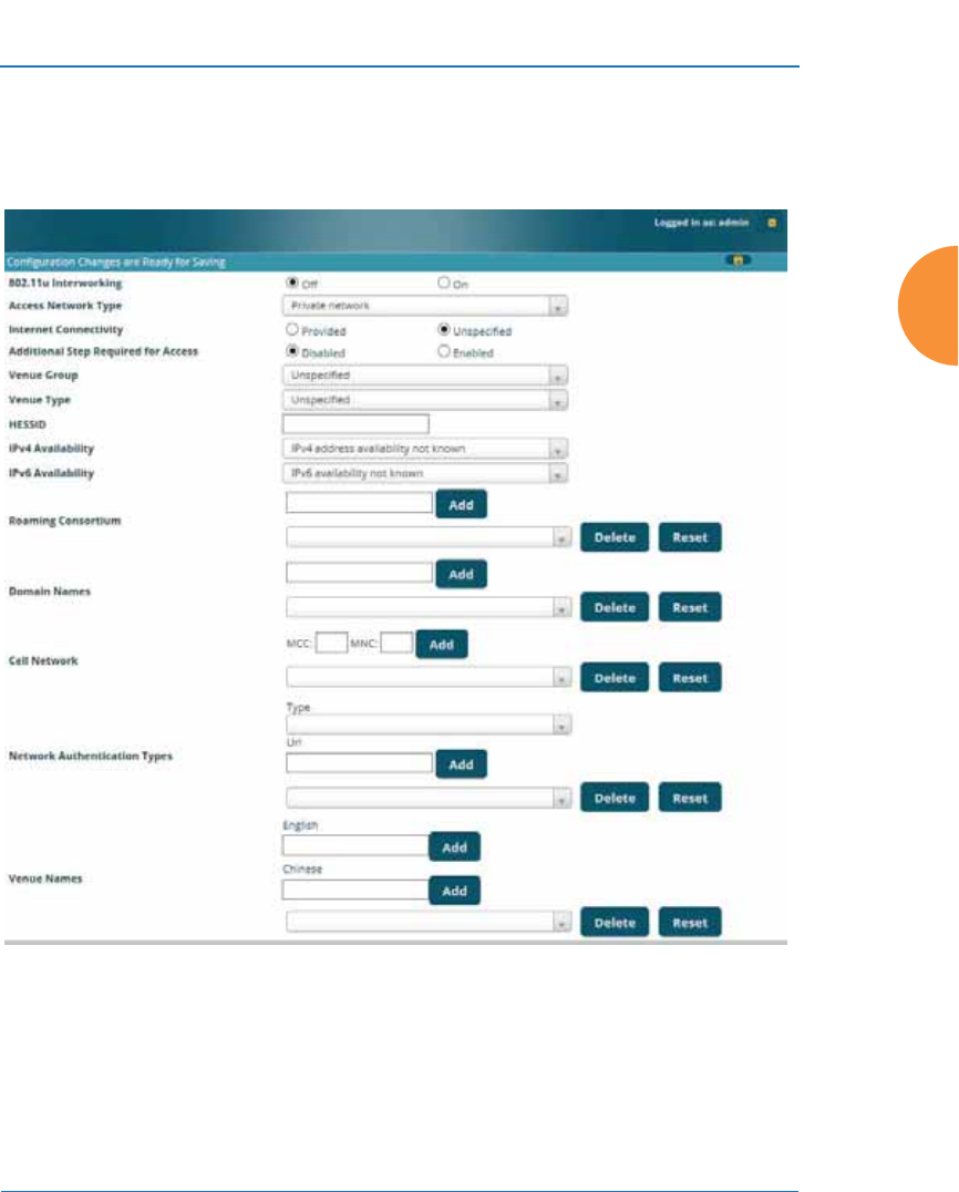
Wireless Access Point
Configuring the Wireless AP 353
z
Cellular Networks. The service network may have arrangements with
one or more cellular service providers who can transparently provide
wireless and Internet connectivity.
Figure 176. 802.11u Global Settings

Wireless Access Point
354 Configuring the Wireless AP
Procedure for Configuring 802.11u Settings
Use this window to establish the 802.11u configuration.
1. 802.11u Internetworking. Click On to enable 802.11u protocol operation.
2. Access Network Type: This indicates the type of network supported by
the access point. The choices are:
a. Chargeable public network
b. Emergency services only network
c. Free public network
d. Personal device network
e. Private network with guest access
f. Test or experimental network
g. Wildcard—all of the networks above are supported.
3. Internet Connectivity. Click Provided if Internet connectivity is available
through the access point from the back end provider to which the mobile
user ends up belonging. Click Unspecified otherwise—for example,
depending on the SLAs (service level agreements) of the mobile user,
Internet access may or may not be provided.
4. Additional Step Required for Access. Click Disabled if no additional
authentication steps will be required to complete the connection and
Enabled otherwise. The available authentication techniques are described
in the Network Authentication Types field (Step 13).
5. Venue Group. Select the general type of venue that the access point is
located in. Various choices are available, including Business, Residential,
and Outdoor. For each Venu e Gr oup , a further set of sub-choices are
available in the Venue Type field below. The particular name of the venue
is specified in the Venue Names field (Step 14).
6. Venue Type. For each of the Venue Group choices, a further set of sub-
choices are available. For example, if you set Venue Group to Assembly,
the choices include Amphitheater, Area, Library, and Theatre.

Wireless Access Point
Configuring the Wireless AP 355
7. HESSID. Enter the globally unique homogeneous ESS ID. This SSID is
marked as being HotSpot 2.0 capable. This SSID attribute is global—if
802.11u is enabled and HotSpot 2.0 is enabled, then all SSIDs will have
HotSpot 2.0 capability.
8. IPv4 Availability. Select the type of IPv4 addressing that will be assigned
by the network upon connection. NATed addresses are IP addresses that
have been changed by mapping the IP address and port number to IP
addresses and new port numbers routable by other networks. Double
NATed addresses go through two levels of NATing. Port restricted IPv4
addresses refer to specific UDP and TCP port numbers associated with
standard Internet services; for example, port 80 for web pages. The
choices for this field are:
a. Double NATed private IPv4 address available
b. IPv4 address not available
c. IPv4 address availability not known
d. Port-restricted IPv4 address available
e. Port-restricted IPv4 address and double NATed IPv4 address
available
f. Port-restricted IPv4 address and single NATed IPv4 address
available
g. Public IPv4 address available
h. Single NATed private IPv4 address available
9. IPv6 Availability. Select the type of IPv6 addressing that is available from
the network upon connection.
a. IPv6 address not available
b. IPv6 address availability not known
c. IPv6 address available

Wireless Access Point
356 Configuring the Wireless AP
10. Roaming Consortium. Each of the roaming consortia has an
organizational identifier (OI) obtained from IEEE that unique identifies
the organization. This is similar to the OUI part of a MAC address. Use
this control to build up a list of OIs for the consortia available. Enter the
OI as a hexadecimal string of between 6 and 30 characters in the Add field
and click Add. The OI will appear in the list. An OI may be deleted by
selecting it in the list and clicking Delete. All OIs may be deleted by
clicking Reset.
11. Domain Names. Use this control to build up a list of domain names.
Enter the name in the Add field and click Add, and it will appear in the
list. A name may be deleted by selecting it in the list and clicking Delete.
All names may be deleted by clicking Reset.
12. Cell Network. Each of the cell networks is identified by a mobile country
code (MCC) and mobile network code (MNC). Use this control to build
up a list of cell networks. Enter the MCC as a three digit number and the
MNC as a two or three digit number and click Add. The cell network will
appear in the list. A cell network may be deleted by selecting it in the list
and clicking Delete. All networks may be deleted by clicking Reset.
13. Network Authentication Types. Each network authentication that is in
use on the network should be specified in this list. The choices are:
a. Acceptance of terms and conditions. This choice displays a web page
asking for the user’s acceptance of terms and conditions of use. The
URL should be specified in the URL field before clicking Add.
b. DNS redirection. Rather than use the DNS server on the network, the
redirection points to a different server.
c. HTTP/HTTPS redirection. This choice causes the user’s first web
page reference to be redirected to a different URL for login or other
information. The URL should be specified in the URL field before
clicking Add.
d. On-line enrollment supported. This choice indicates that the user
may sign up for network access as part of the authentication process.

Wireless Access Point
Configuring the Wireless AP 357
When Add is clicked the authentication type and optional URL will
appear in the list. An authentication type may be deleted by selecting it in
the list and clicking Delete. All authentication types may be deleted by
clicking Reset.
14. Venue Names. The list of names associated with the venue are specified
here. A venue name may be added to the list in English or Chinese. Enter
the name in the appropriate field and click Add. The name will appear in
the list. A name may be deleted by selecting it in the list and clicking
Delete. All names may be deleted by clicking Reset.
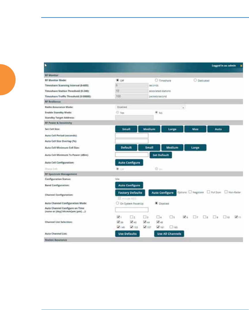
Wireless Access Point
358 Configuring the Wireless AP
Advanced RF Settings
This window allows you to establish RF settings, including automatically
configuring channel allocation and cell size, and configuring radio assurance and
standby modes. Changes you make on this page are applied to all IAPs, without
exception.
Figure 177. Advanced RF Settings
About Standby Mode
Standby Mode supports the AP-to-AP fail-over capability. When you enable
Standby Mode, the AP functions as a backup unit, and it enables its radios if it
detects that its designated target AP has failed. The use of redundant APs to
provide this fail-over capability allows APs to be used in mission-critical

Wireless Access Point
Configuring the Wireless AP 359
applications. In Standby Mode, an AP monitors beacons from the target AP.
When the target has not been heard from for 40 seconds, the standby AP enables
its radios until it detects that the target AP has come back online. Standby Mode is
off by default. Note that you must ensure that the configuration of the standby AP
is correct. This window allows you to enable or disable Standby Mode and specify
the primary AP that is the target of the backup unit. See also, “Failover Planning”
on page 52.
Procedure for Configuring Advanced RF Settings
RF Monitor
1. RF Monitor Mode: RF monitoring permits the operation of features like
intrusion detection. The monitor may operate in Dedicated mode, or in
Timeshare mode which allows the radio to divide its time between
monitoring and acting as a standard radio that allows stations to associate
to it. Timeshare mode is especially useful for small APs with two IAPs,
such as the XR-500/600 and XR-1000 Series, allowing one IAP to be
shared between monitoring the airwaves for problems and providing
services to stations. Settings allow you to give priority to monitoring or
wireless services, depending on your needs. The default Monitor Mode is
Off for the XR-500/600 Series, Timeshare mode for XR-1000 Series, and
Dedicated for higher models.
If Timeshare mode is selected, you may adjust the following settings:
•Timeshare Scanning Interval (6-600): number of seconds between
monitor (off-channel) scans.
•Timeshare Station Threshold (0-240): when the number of stations
associated to the monitor radio exceeds this threshold, scanning is
halted.
•Timeshare Traffic Threshold (0-50000): when the number of packets
per second handled by the monitor radio exceeds this threshold,
scanning is halted.

Wireless Access Point
360 Configuring the Wireless AP
RF Resilience
2. Radio Assurance Mode: When this mode is enabled, the monitor radio
performs loopback tests on the AP. This mode requires RF Monitor Mode
to be enabled (Dedicated or Timeshare mode, see Step 1) to support self-
monitoring functions. It also requires a radio to be set to monitoring
mode (see “Enabling Monitoring on the AP” on page 529).
Operation of Radio Assurance mode is described in detail in “AP Monitor
and Radio Assurance Capabilities” on page 529.
The Radio Assurance mode scans and sends out probe requests on each
channel, in turn. It listens for all probe responses and beacons. These tests
are performed continuously (24/7). If no beacons or probe responses are
observed from a radio for a predetermined period, Radio Assurance
mode will take action according to the preference that you have specified:
•Failure alerts only — The AP will issue alerts in the Syslog, but will
not initiate repairs or reboots.
•Failure alerts & repairs, but no reboots — The AP will issue alerts
and perform resets of one or all of the radios if needed.
•Failure alerts & repairs & reboots if needed — The AP will issue
alerts, perform resets, and schedule reboots if needed.
•Disabled — Disable radio assurance tests (no self-monitoring occurs).
Loopback tests are disabled by default.
3. Enable Standby Mode: Choose Yes to enable this AP to function as a
backup unit for the target AP, or choose No to disable this feature. See
“About Standby Mode” on page 358.
4. Standby Target Address: If you enabled the Standby Mode, enter the
MAC address of the target AP (i.e., the address of the primary AP that is
being monitored and backed up by this AP). To find this MAC address,
open the AP Info window on the target AP, and use the Gigabit1 MAC
Address.

Wireless Access Point
Configuring the Wireless AP 361
RF Power and Sensitivity
For an overview of RF power and cell size settings, please see “Capacity and Cell
Sizes” on page 36 and “Fine Tuning Cell Sizes” on page 37.
5. Set Cell Size: Cell Size may be set globally for all enabled IAPs to Auto,
Large, Medium, Small, or Max using the buttons.
6. Auto Cell Period (seconds): You may set up auto-configuration to run
periodically, readjusting optimal cell sizes for the current conditions.
Enter a number of seconds to specify how often auto-configuration will
run. If you select None, then auto-configuration of cell sizing will not be
run periodically. You do not need to run Auto Cell often unless there are a
lot of changes in the environment. If the RF environment is changing
often, running Auto Cell every twenty-four hours (86400 seconds) should
be sufficient). The default value is None.
7. Auto Cell Size Overlap (%): Enter the percentage of cell overlap that will
be allowed when the AP is determining automatic cell sizes. For 100%
overlap, the power is adjusted such that neighboring APs that hear each
other best will hear each other at -70dB. For 0% overlap, that number is -
90dB. The default value is 50%.
8. Auto Cell Min Cell Size: Use this setting if you wish to set the minimum
cell size that Auto Cell may assign. The values are Default, Large,
Medium, or Small.
9. Auto Cell Min Tx Power (dBm): Enter the minimum transmit power that
the AP can assign to a radio when adjusting automatic cell sizes. The
default value is 10.
#To use the Auto Cell Size feature, the following additional settings are
required: all IAPs that will use Auto Cell must have Cell Size set to auto.
See “Procedure for Manually Configuring IAPs” on page 314.
It is not necessary for RF Monitor Mode to be turned on, and you don’t need
to have any radio set to monitor mode. See “RF Monitor” on page 359.

Wireless Access Point
362 Configuring the Wireless AP
10. Auto Cell Configuration: Click this button to instruct the AP to
determine and set the best cell size for each enabled IAP whose Cell Size
is auto on the IAP Settings window, based on changes in the
environment. This is the recommended method for setting cell size. You
may look at the Tx and Rx values on the IAP Settings window to view the
cell size settings that were applied.
11. Sharp Cell: This feature reduces interference between neighboring APs
or other Access Points by limiting to a defined boundary (cell size) the
trailing edge bleed of RF energy. Choose On to enable the Sharp Cell
functionality, or choose Off to disable this feature. See also, “Fine Tuning
Cell Sizes” on page 37. This feature is available on 802.11n radios on APs,
but not on 802.11ac radios.
The Sharp Cell feature only works when the cell size is Small, Medium, or
Large (or Auto) — but not Max. If IAP cell size is set to Max, the Sharp
Cell feature will be disabled for that radio.
RF Spectrum Management
12. Configuration Status: Shows the status of auto channel configuration. If
an operation is in progress, the approximate time remaining until
completion is displayed; otherwise Idle is displayed.
13. Band Configuration: Automatic band configuration is the recommended
method for assigning bands to the abgn IAPs. It runs only on command,
assigning IAPs to the 2.4GHz or 5GHz band when you click the Auto
Configure button. The AP uses its radios to listen for other APs on the
same channel, and it assigns bands based on where it finds the least
interference.
Auto band assigns as many IAPs to the 5 GHz band as possible when
there are other APs within earshot. It does this by determining how many
APs are in range and then picking the number of radios to place in the 2.4
GHz band. Note that for another AP to be considered to be in range, the
other AP must be visible via both the wireless and wired networks—the
AP must be listed in the Network Map table, its entry must have In

Wireless Access Point
Configuring the Wireless AP 363
Range set to Yes, and it must have at least one active IAP with an SSID
that has broadcast enabled.
Auto band runs separately from auto channel configuration. If a radio’s
band is changed, associated stations will be disconnected and will then
reconnect.
14. Channel Configuration: Automatic channel configuration is a method
for channel allocation. When the AP performs auto channel
configuration, you may optionally instruct it to first negotiate with any
other nearby APs that have been detected, to determine whether to
stagger the start time for the procedure slightly. Thus, nearby APs will not
run auto channel at the same time. This prevents APs from interfering
with each other’s channel assignments.
The Configuration Status field displays whether an Auto Configure
cycle is currently running on this AP or not.
Click Auto Configure to instruct the AP to determine the best channel
allocation settings for each enabled IAP and select the channel
automatically, based on changes in the environment. This is the
recommended method for channel allocation (see “RF Spectrum
Management” on page 362). The following options may be selected for
auto configuration:
•Negotiate: negotiate air-time with other APs before performing a full
scan. Negotiating is slower, but if multiple APs are configuring
channels at the same time the Negotiate option ensures that multiple
APs don't select the same channels. Turning off the Negotiate option
allows the Auto Configure button to manually perform auto channel
without waiting, and may be used when you know that no other
nearby APs are configuring their channels.
#Note that Auto Channel normally assigns individual channels. However, if
you select Auto bond 5GHz channels on the Global Settings .11n page,
and have 40MHz channels set up prior to running Auto Channel, those
bonds will be preserved. 80MHz bonds will not be preserved.

Wireless Access Point
364 Configuring the Wireless AP
•Full Scan: perform a full traffic scan on all channels on all IAPs to
determine the best channel allocation.
•Non-Radar: give preference to channels without radar-detect. See
table in “Procedure for Configuring Global 802.11an IAP Settings” on
page 335.
•Include WDS: automatically assign 5GHz to WDS client links.
Click Factory Defaults if you wish to instruct the AP to return all IAPs to
their factory preset channels. APs do not use the same factory preset
values for channel assignments. Instead, if the AP has been deployed for
a while and already has data from the spectrum analyzer and Xirrus
Roaming Protocol about channel usage on neighboring APs, it performs a
quick auto channel using that information (without doing a full RF scan)
to make an intelligent choice of channel assignments. If the AP has been
rebooted and has no saved configuration or is just being deployed for the
first time, it has no prior data about its RF environment. In this case, it
will pick a set of compatible channel assignments at random.
15. Auto Channel Configuration Mode: This option allows you to instruct
the AP to auto-configure channel selection for each enabled IAP when the
AP is powered up. Choose On AP PowerUp to enable this feature, or
choose Disabled to disable this feature.
16. Auto Channel Configure on Time: This option allows you to instruct the
AP to auto-configure channel selection for each enabled IAP at a time you
specify here. Leave this field blank unless you want to specify a time at
which the auto-configuration utility is initiated. Time is specified in hours
and minutes, using the format: [day]hh:mm [am|pm]. If you omit the
optional day specification, channel configuration will run daily at the
#On XR-500/600 and XR-1000 Series models, the Factory Defaults button
will not restore iap1 to monitor mode. You will need to restore this setting
manually. Also, you may need to set RF Monitor Mode to Timeshare
Mode again - see “RF Monitor” on page 359.

Wireless Access Point
Configuring the Wireless AP 365
specified time. If you do not specify am or pm, time is interpreted in 24-
hour military time. For example, Sat 11:00 pm and Saturday 23:00 are
both acceptable and specify the same time.
17. Channel List Selection: This list selects which channels are available to
the auto channel algorithm. Channels that are not checked are left out of
the auto channel selection process. Note that channels that have been
locked by the user are also not available to the auto channel algorithm.
18. Auto Channel List: Use All Channels selects all available channels (this
does not include locked channels). Use Defaults sets the auto channel list
back to the defaults. This omits newer channels (100-140) — many
wireless NICs don’t support these channels.
Station Assurance
Station assurance monitors the quality of the connections that users are
experiencing on the wireless network. You can quickly detect stations that are
having problems and take steps to correct them. Use these settings to establish
threshold values for errors and other problems. Station assurance is enabled by
default, with a set of useful default thresholds that you may adjust as desired.
When a connection is experiencing problems and reaches one of these thresholds
in the specified period of time, the AP responds with several actions: an event is
triggered, a trap is generated, and a Syslog message is logged. For example, if a
client falls below the threshold for Min Average Associated Time, this
“bouncing” behavior might indicate roaming problems with the network’s RF
design, causing the client to bounce between multiple APs and not stay connected
longer than the time to re-associate and then jump again. This can be corrected
with RF adjustments. Station assurance alerts you to the fact that this station is
encountering problems.
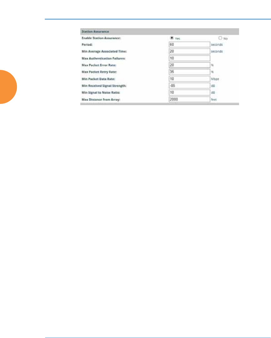
Wireless Access Point
366 Configuring the Wireless AP
Figure 178. Station Assurance (Advanced RF Settings)
19. Enable Station Assurance: This is enabled by default. Click No if you
wish to disable it, and click Yes to re-enable it. When station assurance is
enabled, the AP will monitor connection quality indicators listed below
and will display associated information on the Station Assurance Status
page. When a threshold is reached, an event is triggered, a trap is
generated, and a Syslog message is logged.
20. Period: In seconds, the period of time for a threshold to be reached. For
example, the AP will check whether Max Authentication Failures has
been reached in this number of seconds.
21. Min Average Associated Time: (seconds) Station assurance detects
whether the average length of station associations falls below this
threshold during a period.
22. Max Authentication Failures: Station assurance detects whether the
number of failed login attempts reaches this threshold during a period.
23. Max Packet Error Rate: (%) Station assurance detects whether the packet
error rate percentage reaches this threshold during a period.
24. Max Packet Retry Rate: (%) Station assurance detects whether the packet
retry rate percentage reaches this threshold during a period.
25. Min Packet Data Rate: (Mbps) Station assurance detects whether the
packet data rate falls below this threshold during a period.

Wireless Access Point
Configuring the Wireless AP 367
26. Min Received Signal Strength: (dB) Station assurance detects whether
the strength of the signal received from the station falls below this
threshold during a period.
27. Min Signal to Noise Ratio: (dB) Station assurance detects whether the
ratio of signal to noise received from the station falls below this threshold
during a period.
28. Max Distance from AP: Min Received Signal Strength: (feet) Station
assurance detects whether the distance of the station from the AP reaches
this threshold during a period.
See Also
Coverage and Capacity Planning
Global Settings .11an
Global Settings .11bgn
Global Settings .11n
IAPs
IAP Settings
Radio Assurance
Hotspot 2.0
Understanding Hotspot 2.0
Hotspot 2.0 is a part of the Wi-Fi Alliance’s Passpoint certification program. It
specifies additional information above and beyond that found in 802.11u, which
allows mobile clients to automatically discover, select, and connect to networks
based on preferences and network optimization. Mobile clients that support
Hotspot 2.0 are informed of an access point’s support via its beacon message.
Hotspot 2.0 messages forward several types of information to clients, including:
z
Uplink and Downlink Speeds
z
Link Status
z
Friendly Name
z
Connection Capabilities The access point will restrict the protocols that
can be used by a specification of protocol and port numbers.

Wireless Access Point
368 Configuring the Wireless AP
Procedure for Hotspot 2.0 Settings
Use this window to establish the Hotspot 2.0 configuration.
1. Hotspot 2.0. Click Enabled to enable Hotspot 2.0 operation.
2. Downstream Group-addressed Forwarding. Click Enabled to allow the
access point to forward group-addressed traffic (broadcast and multicast)
to all connected devices. Click Disabled to cause the access point to
convert group-addressed traffic to unicast messages.
3. WAN Downlink Speed. Enter the WAN downlink speed in kbps into the
field.
4. WAN Uplink Speed. Enter the WAN uplink speed in kbps into the field.
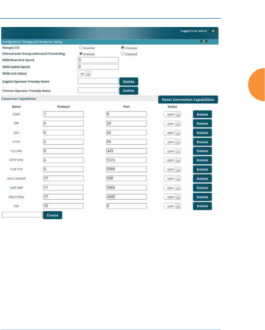
Wireless Access Point
Configuring the Wireless AP 369
Figure 179. Hotspot 2.0 Settings
5. English/Chinese Operator Friendly Name. Enter an English or Chinese
name into one of the fields. An incorrectly entered name can be deleted
by clicking the corresponding Delete.
6. Connection Capabilities. A Hotspot 2.0 access point limits the particular
protocols that clients may use. The set of default protocols is shown
initially. This table specifies the protocols in terms of:
a. A common Name, such as FTP or HTTP.
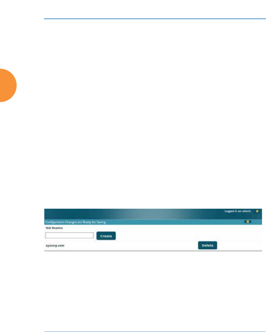
Wireless Access Point
370 Configuring the Wireless AP
b. A Protocol number. For example 1 for ICMP, 6 for TCP, 17 for UDP,
and 50 for Encapsulated Security Protocol in IPsec VPN connections.
c. Port number for UDP/TCP connection.
d. Status: one of open, closed or unknown.
Any of the entries may be deleted by clicking the corresponding Delete
button. New entries may be created by entering the name of the protocol
in the box beside the Create button, and then clicking Create. The new
protocol will be added to the list with zeros in the protocol fields and
unknown for the status. Enter the appropriate Protocol and Port values
before setting the Status field to open.
NAI Realms
Understanding NAI Realm Authentication
A network access identifier (NAI) is a specification of a particular user. A NAI
takes the general form of an e-mail address. Examples of NAIs are:
joe@example.com
fred@foo-9.example.com
jack@3rd.depts.example.com
fred.smith@example.com
Figure 180. NAI Realms
The NAI Realm is the part of the NAI following the @ sign. For example, you
might enter: example.com, 3rd.depts.example.com, and foo-9.example.com. Use
the NAI Realms page, in conjunction with the NAI EAP page, to specify the
authentication techniques to be used to access that realm with appropriate
parameters.
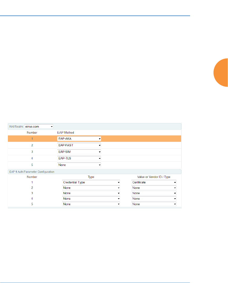
Wireless Access Point
Configuring the Wireless AP 371
Procedure for NAI Realms Settings
Use this window to establish the names of the supported realms.
1. Enter the realm name. Enter the name of a realm in the box to the left of
the Create button and click Create. The realm will be added to the NAI
Realms list. Any of the realms may be deleted by clicking the
corresponding Delete button.
2. Enter Authentication Information. The NAI EAP page is used to specify
authentication for a realm. Click on the name of a realm to go to the NAI
EAP page for that realm. See “NAI EAP” on page 371.
NAI EAP
This window allows specification of the authentication techniques for a realm.
Figure 181. NAI EAP
Procedure for NAI Realms Settings
1. Select the realm to be configured in the NAI Realm drop down.
2. Select EAP Methods. Each realm may support up to five EAP
authentication methods. Beside each of the five numbers (1, 2, 3, 4, 5)
select the method from the drop down. The choices are:

Wireless Access Point
372 Configuring the Wireless AP
•EAP-AKA
•EAP-AKA’ (EAP-AKA prime)
•EAP-FAST
•EAP-MSCHAP-V2
•EAP-SIM
•EAP-TLS
•EAP-TTLS
•GTC
•MD5-Challenge
•None
•PEAP
3. Specify Authentication Parameters. Each of the authentication methods
may specify up to five authentication parameters. To specify the
parameters click on the number corresponding to the authentication
method; i.e. 1, 2, 3, 4, or 5. This displays the EAP n Auth Parameter
Configuration below the list of EAP Methods. For up to five of the
parameters, select the Type and Value or Vendor ID / Type. The choices
for the Type are:
•Credential Type
•Expanded EAP Method
•Expanded Inner EAP Method
•Inner Authentication EAP Method Type
•Non-EAP Inner Authentication Type
•None
•Tunneled EAP Method Credential Type
For each type, a value or a vendor ID and type must be specified, as
applicable.
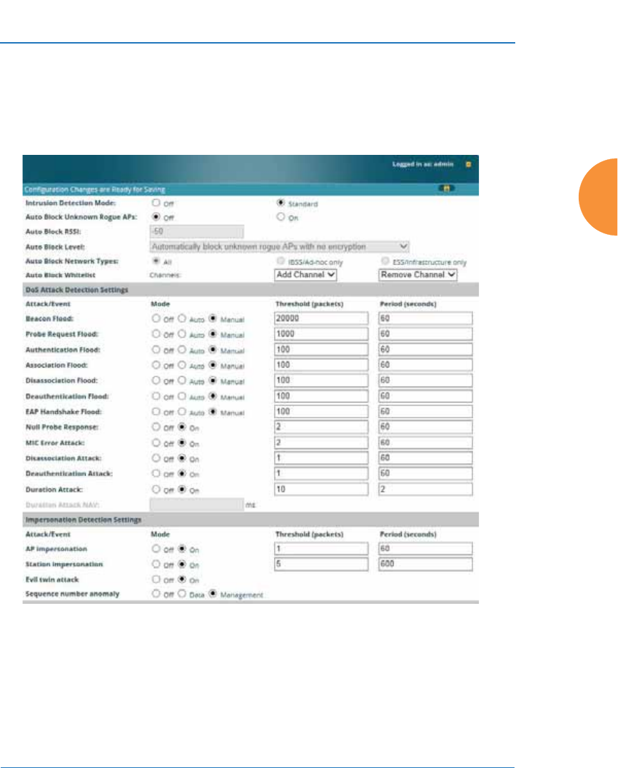
Wireless Access Point
Configuring the Wireless AP 373
Intrusion Detection
The Xirrus AP employs a number of IDS/IPS (Intrusion Detection System/
Intrusion Prevention System) strategies to detect and prevent malicious attacks on
the wireless network. Use this window to adjust intrusion detection settings.
Figure 182. Intrusion Detection Settings

Wireless Access Point
374 Configuring the Wireless AP
The AP provides a suite of intrusion detection and prevention options to improve
network security. You can separately enable detection of the following types of
problems:
z
Rogue Access Point Detection and Blocking
Unknown APs are detected, and may be automatically blocked based on
a number of criteria. See “About Blocking Rogue APs” on page 376.
z
Denial of Service (DoS) or Availability Attack Detection
A DoS attack attempts to flood an AP with communications requests so
that it cannot respond to legitimate traffic, or responds so slowly that it
becomes effectively unavailable. The AP can detect a number of types of
DoS attacks, as described in the table below. When an attack is detected,
the AP logs a Syslog message at the Alert level.
z
Impersonation Detection
These malicious attacks use various techniques to impersonate a
legitimate AP or station, often in order to eavesdrop on wireless
communications. The AP detects a number of types of impersonation
attacks, as described in the table below. When an attack is detected, the
AP logs a Syslog message at the Alert level.
Type of Attack Description
DoS Attacks
Beacon Flood Generating thousands of counterfeit 802.11 beacons to
make it hard for stations to find a legitimate AP.
Probe Request
Flood Generating thousands of counterfeit 802.11 probe requests
to overburden the AP.
Authentication
Flood Sending forged Authenticates from random MAC
addresses to fill the AP's association table.
Association
Flood Sending forged Associates from random MAC addresses
to fill the AP's association table.

Wireless Access Point
Configuring the Wireless AP 375
Disassociation
Flood Flooding the AP with forged Disassociation packets.
Deauthentication
Flood Flooding the AP with forged Deauthenticates.
EAP Handshake
Flood Flooding an AP with EAP-Start messages to consume
resources or crash the target.
Null Probe
Response Answering a station probe-request frame with a null SSID.
Many types of popular NIC cards cannot handle this
situation, and will freeze up.
MIC Error Attack Generating invalid TKIP data to exceed the AP's MIC error
threshold, suspending WLAN service.
Disassociation
Attack (Omerta) Sending forged disassociation frames to all stations on a
channel in response to data frames.
Deauthentication
Attack Sending forged deauthentication frames to all stations on
a channel in response to data frames.
Duration Attack
(Duration Field
Spoofing)
Injecting packets into the WLAN with huge duration
values. This forces the other nodes in the WLAN to keep
quiet, since they cannot send any packet until this value
counts down to zero. If the attacker sends such frames
continuously it silences other nodes in the WLAN for long
periods, thereby disrupting the entire wireless service.
Impersonation Attacks
AP
impersonation Reconfiguring an attacker's MAC address to pose as an
authorized AP. Administrators should take immediate
steps to prevent the attacker from entering the WLAN.
Station
impersonation Reconfiguring an attacker's MAC address to pose as an
authorized station. Administrators should take immediate
steps to prevent the attacker from entering the WLAN.
Evil twin attack Masquerading as an authorized AP by beaconing the
WLAN's service set identifier (SSID) to lure users.
Type of Attack Description

Wireless Access Point
376 Configuring the Wireless AP
About Blocking Rogue APs
If you classify a rogue AP as blocked (see “Rogue Control List” on page 264), then
the AP will take measures to prevent stations from staying associated to the
rogue. When the monitor radio is scanning, any time it hears a beacon from a
blocked rogue it sends out a broadcast “deauth” signal using the rogue's BSSID
and source address. This has the effect of disconnecting all of a rogue AP’s clients
approximately every 5 to 10 seconds, which is enough to make the rogue
unusable.
The Intrusion Detection window allows you to set up Auto Block parameters so
that unknown APs get the same treatment as explicitly blocked APs. This may
result in many APs being blocked so use caution with auto block, and be sure to
abide by applicable regulations. See the Caution on page 377. By default, auto
blocking is turned off. Auto blocking provides two parameters for qualifying
blocking so that APs must meet certain criteria before being blocked. This keeps
the AP from blocking every AP that it detects. You may:
z
Set a minimum RSSI value for the AP — for example, if an AP has an RSSI
value of -90, it is probably a harmless AP belonging to a neighbor and not
in your building.
z
Block based on encryption level.
z
Block based on whether the AP is part of an ad hoc network or
infrastructure network.
z
Specify channels to be whitelisted. Rogues discovered on these channels
are excluded from auto blocking. This allows specified channels to be
freely used by customer or guests for their APs.
Sequence
number anomaly A sender may use an Add Block Address request (ADDBA
- part of the Block ACK mechanism) to specify a sequence
number range for packets that the receiver can accept.
An attacker spoofs an ADDBA request, asking the receiver
to reset its sequence number window to a new range. This
causes the receiver to drop legitimate frames, since their
sequence numbers will not fall in that range.
Type of Attack Description

Wireless Access Point
Configuring the Wireless AP 377
RF Intrusion Detection and Auto Block Mode
Procedure for Configuring Intrusion Detection
1. Intrusion Detection Mode: This option allows you to choose the
Standard intrusion detection method, or you can choose Off to disable
this feature. See “AP Monitor and Radio Assurance Capabilities” on
page 529 for more information.
•Standard — enables the monitor radio to collect Rogue AP
information.
•Off — intrusion detection is disabled.
2. Auto Block Unknown Rogue APs: Enable or disable auto blocking (see
“About Blocking Rogue APs” on page 376). You will be shown a Caution
statement (below) and the WMI will ask whether you wish to proceed.
!CAUTION: Selecting and engaging Auto Block may result in
many APs being blocked. User caution in configuring and
operating any form of Auto Block is highly recommended, as
auto-blocking may be subject to significant statutory and U.S.
Federal Communications Commission (FCC) regulatory
controls, restrictions, enforcement actions and penalties.
User is solely responsible for making sure that all uses of any
auto-blocking feature(s) of this product are fully compliant with
all applicable statutes, regulations, FCC enforcement actions
and rules, etc. regarding Wi-Fi blocking. See for example FCC
Enforcement Advisory No. 2015-01 dated January 27, 2015.
All uses of any auto-blocking feature(s) in this product are solely
at User's discretion and individual choice. User assumes all
liability and responsibility for all such uses. Xirrus assumes no
liability or responsibility for any discretionary decision by User
to configure, engage and to use any auto-blocking feature(s) of
this product.

Wireless Access Point
378 Configuring the Wireless AP
Note that in order to set Auto Block RSSI and Auto Block Level, you must
set Auto Block Unknown Rogue APs to On. Then the remaining Auto
Block fields will be active.
3. Auto Block RSSI: Set the minimum RSSI for rogue APs to be blocked.
APs with lower RSSI values will not be blocked. They are assumed to be
farther away, and probably belonging to neighbors and posing a minimal
threat.
4. Auto Block Level: Select rogue APs to block based on the level of
encryption that they are using. The choices are:
•Automatically block unknown rogue APs regardless of encryption.
•Automatically block unknown rogue APs with no encryption.
•Automatically block unknown rogue APs with WEP or no
encryption.
5. Auto Block Network Types: Select rogues to automatically block by
applying the criteria above only to networks of the type specified below.
The choices are:
•All — the unknown rogues may be part of any wireless network.
•IBSS/AD Hoc only — only consider auto blocking rogues if they
belong to an ad hoc wireless network (a network of client devices
without a controlling Access Point, also called an Independent Basic
Service Set — IBSS).
•ESS/Infrastructure only — only consider auto blocking rogue APs if
they are in infrastructure mode rather than ad hoc mode.
6. Auto Block Whitelist: Use this list to specify channels to be excluded
from automatic blocking. If you have enabled Auto Block, it will not be
applied to rogues detected on the whitelisted channels. Use the Add
Channel drop-down to add entries to the Channels list, one at a time.
You can delete entries from the list by selecting them from the Remove
Channel drop-down list.

Wireless Access Point
Configuring the Wireless AP 379
DoS Attack Detection Settings
7. Attack/Event: The types of DoS attack that you may detect are described
in the Type of Attack Table page 374. Detection of each attack type may be
separately enabled or disabled. For each attack, a default Threshold and
Period (seconds) are specified. If the number of occurrences of the type of
packet being detected exceeds the threshold in the specified number of
seconds, then the AP declares that an attack has been detected. You may
modify the Threshold and Period.
For the Flood attack settings, you also have a choice of Auto or Manual.
•Manual mode — threshold and period settings are used to detect a
flood. Packets received are simply counted for the specified time
period and compared against the flood threshold. The default for all
of the floods is Manual mode.
•Auto mode — the AP analyzes current traffic for packets of a given
type versus traffic over the past hour to determine whether a packet
flood should be detected. In this mode, threshold and period settings
are ignored. This mode is useful for floods like beacon or probe
floods, where the numbers of such packets detected in the air can
vary greatly from installation to installation.
8. Duration Attack NAV (ms): For the duration attack, you may also modify
the default duration value that is used to determine whether a packet
may be part of an attack. If the number of packets having at least this
duration value exceeds the Threshold number in the specified Period, an
attack is detected.
Impersonation Detection Settings
9. Attack/Event: The types of impersonation attack that you may detect are
described in Impersonation Attacks page 375. Detection of each attack
type may be turned On or Off separately. For AP or Station
Impersonation attacks, a default Threshold and Period (seconds) are
specified. If the number of occurrences of the type of packet being
detected exceeds the threshold in the specified number of seconds, then
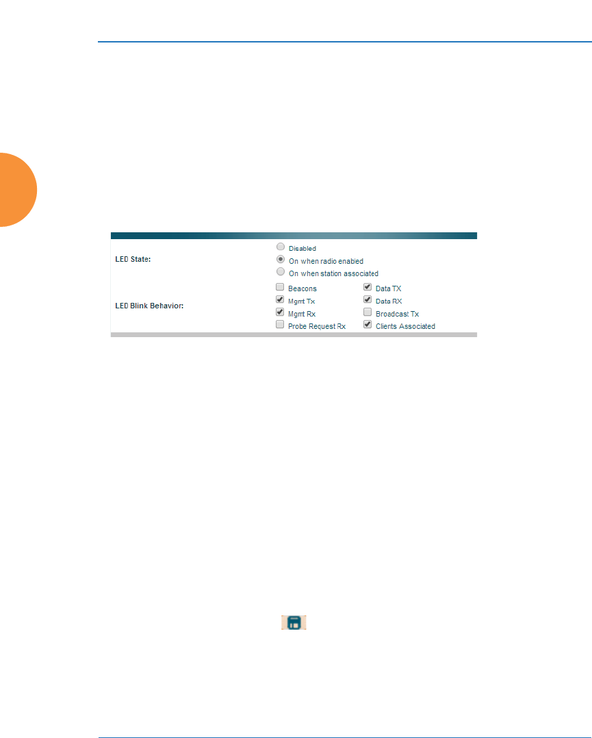
Wireless Access Point
380 Configuring the Wireless AP
the AP declares that an attack has been detected. You may modify the
Threshold and Period.
10. Sequence number anomaly: You may specify whether to detect this type
of attack in Data traffic or in Management traffic, or turn Off this type of
detection.
LED Settings
This window assigns behavior preferences for the AP’s IAP LEDs.
Figure 183. LED Settings
Procedure for Configuring the IAP LEDs
1. LED State: This option determines which event triggers the LEDs, either
when the IAP is enabled or when a station associates with the IAP.
Choose On Radio Enabled or On First Association, as desired. You may
also choose Disabled to keep the LEDs from being lit. The LEDs will still
light during the boot sequence, then turn off.
2. LED Blink Behavior: This option allows you to select when the IAP LEDs
blink, based on the activities you check here. From the choices available,
select one or more activities to trigger when the LEDs blink. For default
behavior, see “AP LED Operating Sequences” on page 73.
3. Click the Save button if you wish to make your changes permanent.
See Also
Global Settings
Global Settings .11an
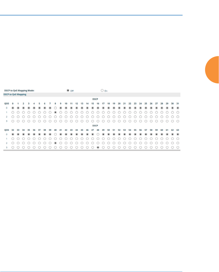
Wireless Access Point
Configuring the Wireless AP 381
Global Settings .11bgn
IAPs
LED Boot Sequence
DSCP Mappings
DSCP is the 6-bit Differentiated Services Code Point (DiffServ) field in the IPv4 or
IPv6 packet header, defined in RFC2474 and RFC2475. The DSCP value classifies
the packet to determine the Quality of Service (QoS) required. DSCP replaces the
outdated Type of Service (TOS) field.
Figure 184. DSCP Mappings
The DSCP Mappings page shows the default mapping of each of the 64 DSCP
values to one of the AP’s four QoS levels, and allows you to change these
mappings.
For a detailed discussion of the operation of QoS and DSCP mappings on the AP,
please see “Understanding QoS Priority on the Wireless AP” on page 271.
Procedure for Configuring DSCP Mappings
1. DSCP to QoS Mapping Mode: Use the On and Off buttons to enable or
disable the use of the DSCP mapping table to determine the QoS level
applied to each packet.

Wireless Access Point
382 Configuring the Wireless AP
2. DSCP to QoS Mapping: The radio buttons in this table show all DSCP
values (0 to 63), and the QoS level to which each is mapped. To change the
QoS level applied to a DSCP value, click the desired QoS level (0 to 3)
underneath it.
Roaming Assist
Roaming assist is a Xirrus feature that helps clients roam to APs that will give
them high quality connections. Some smart phones and tablets will stay
connected to a radio with poor signal quality, even when there’s a radio with
better signal strength within range. When roaming assist is triggered, the AP
“assists” the device by deauthenticating it when certain parameters are met. This
encourages a client with a high roaming threshold (i.e., a device that may not
roam until signal quality has seriously dropped) to move to an AP that gives it a
better signal. The deauthentication is meant to cause the client to choose a
different radio. You can specify the device types that will be assisted in roaming.
The roaming threshold is the difference in signal strength between radios that will
trigger a deauthentication. If the client’s signal is lower than the sum of the
threshold and the stronger neighbor radio’s RSSI, then we “assist” the client. For
example:
Threshold = -5
RSSI of neighbor AP = -65
RSSI of client = -75
-75 < (-5 + -65) : Therefore client will roam
Another example:
Threshold = -15
RSSI of neighbor AP = -60
RSSI of station = -70
-70 > (-15 + -60) : Client will not roam
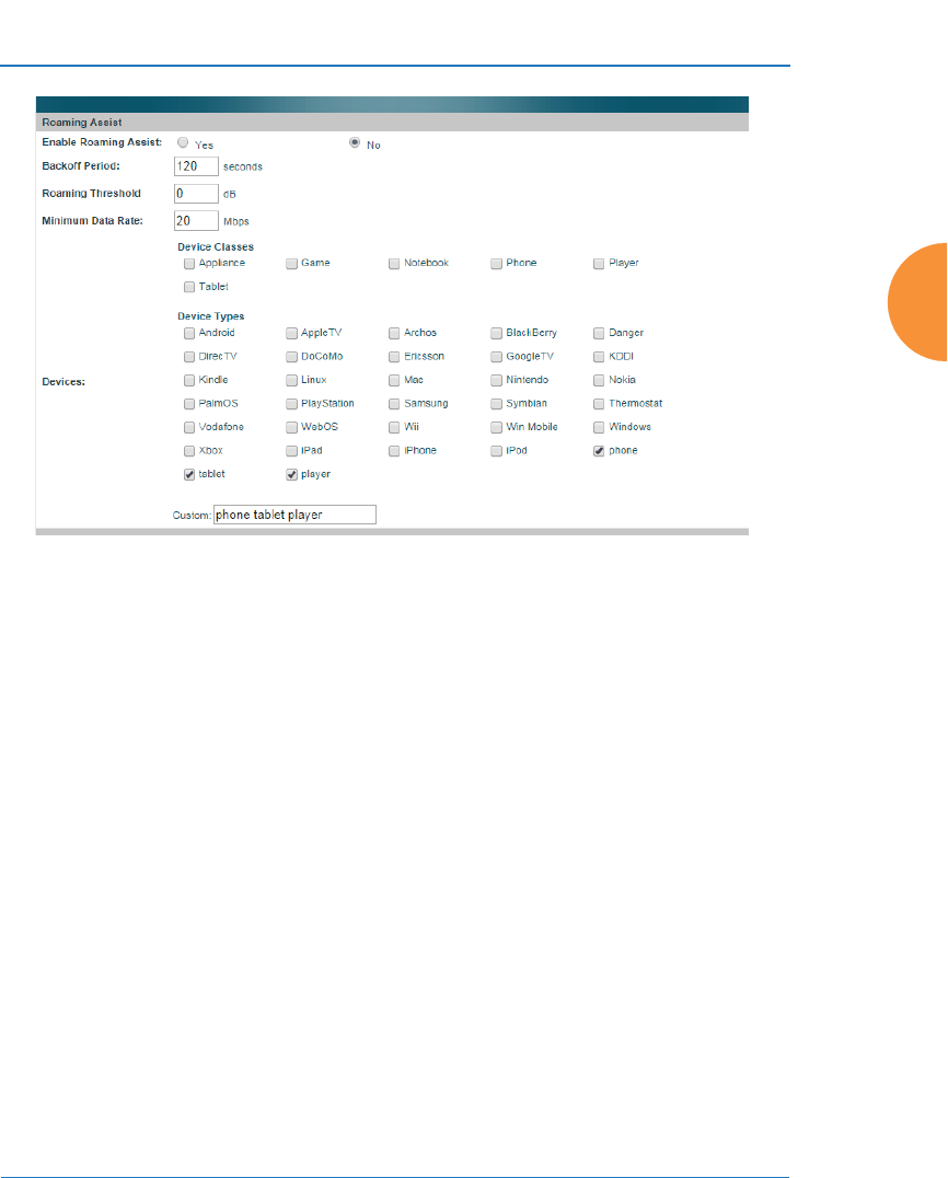
Wireless Access Point
Configuring the Wireless AP 383
Figure 185. Roaming Assist
Procedure for Configuring Roaming Assist
1. Enable Roaming Assist: Use the Yes and No buttons to enable or disable
this feature.
2. Backoff Period: After deauthenticating a station, it may re-associate to
the same radio. To prevent the AP from repeatedly deauthenticating the
station when it comes back, there is a backoff period. This is the number
of seconds the station is allowed to stay connected before another
deauthentication.
3. Roaming Threshold: This is the difference in signal strength between
radios that will trigger a deauthentication, as described in the discussion
above. In most cases, this will be a negative number. Triggering occurs
regardless of whether the data rate falls below the Minimum Data Rate.
4. Minimum Data Rate: Roaming assist will be triggered if the station’s
packet data rate is below this value (1-99 Mbps), regardless of whether
the Roaming Threshold has been reached.

Wireless Access Point
384 Configuring the Wireless AP
5. Device Classes: If you select any classes of device, such as Phone and
Notebook, then roaming assist will only be applied to those kinds of
stations. Many small, embedded devices (such as phones, tablets, and
music players) are sticky—they have high roaming thresholds that tend
to keep them attached to the same radio despite the presence of radios
with better signal strength. You may check off one or more entries, but
use care since roaming assist may cause poor results in some cases.
If no Device Classes or Device Types are selected, then all devices are
included in roaming assist. If you select entries in both Device Classes
and Device Types, then stations matching any of your selected types/
classes will be assisted when the Roaming Threshold or Minimum Data
Rate trigger is satisfied.
6. Device Types: If you select any types of device, such as iPhone and
Samsung, then roaming assist will only be applied to those types of
stations and to your selected Device Types as well, when the Roaming
Threshold or Minimum Data Rate trigger is satisfied. If no Device Classes
or Device Types are selected, then all devices are considered for roaming
assist.
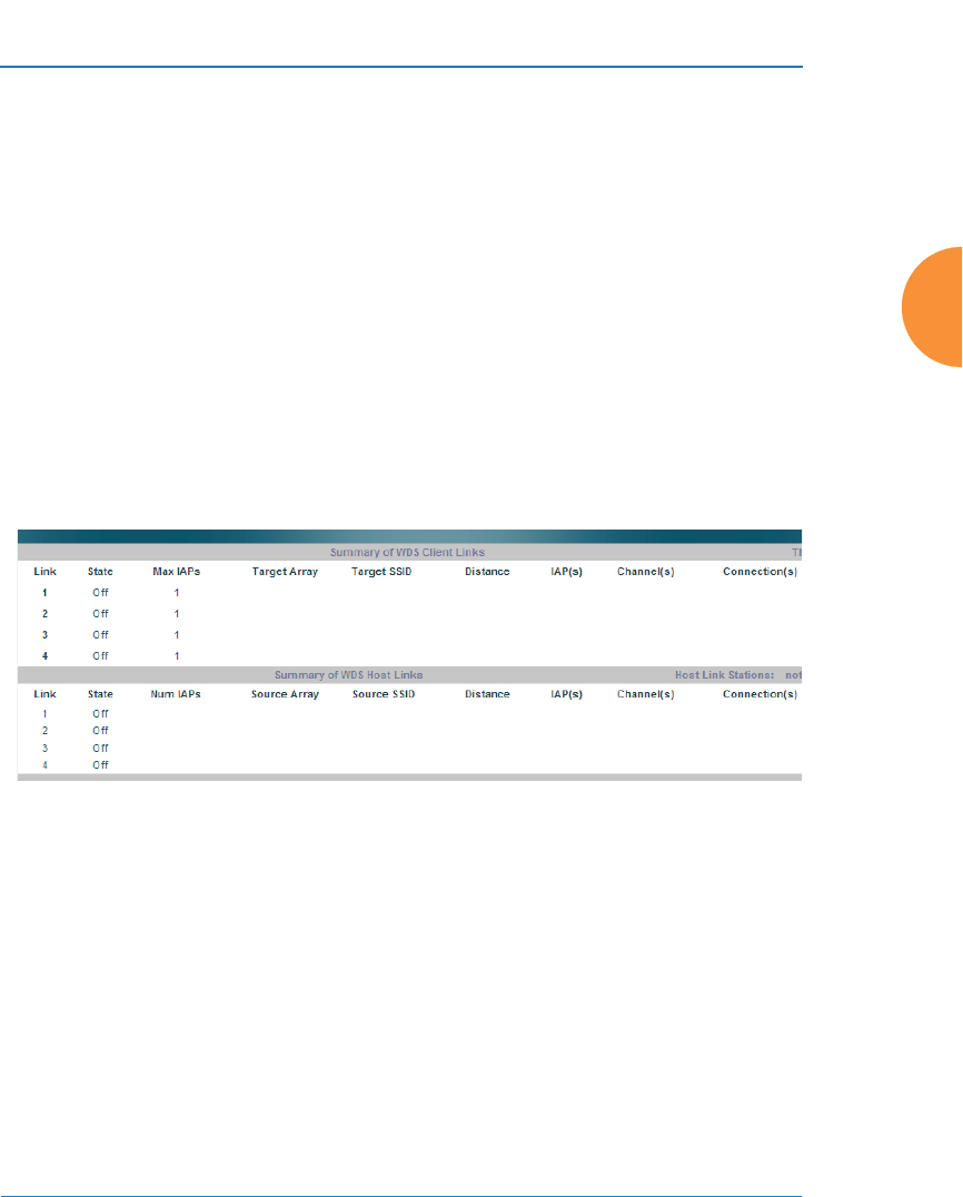
Wireless Access Point
Configuring the Wireless AP 385
WDS
This is a status-only window that provides an overview of all WDS links that have
been defined. Wireless Distribution System (WDS) is a system that enables the
interconnection of access points wirelessly, allowing your wireless network to be
expanded using multiple access points without the need for a wired backbone to
link them. The Summary of WDS Client Links shows the WDS links that you
have defined on this AP and identifies the target AP for each by its base MAC
address. The Summary of WDS Host Links shows the WDS links that have been
established on this AP as a result of client APs associating to this AP (i.e., the
client APs have this AP as their target). The summary identifies the source (client)
AP for each link. Both summaries identify the IAPs that are part of the link and
whether the connection for each is up or down. See “WDS Planning” on page 63
for an overview.
Figure 186. WDS
About Configuring WDS Links
A WDS link connects a client AP and a host AP (see Figure 187 on page 386). The
host must be the AP that has a wired connection to the LAN. Client links from one
or more APs may be connected to the host, and the host may also have client
links. See “WDS Planning” on page 63 for more illustrations.
The configuration for WDS is performed on the client AP only, as described in
“WDS Client Links” on page 387. No WDS configuration is performed on the host
AP. First you will set up a client link, defining the target (host) AP and SSID, and
the maximum number of IAPs in the link. Then you will select the IAPs to be used
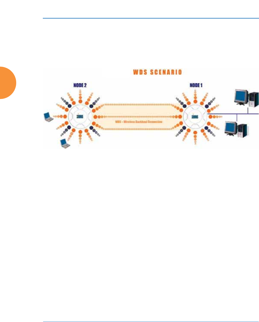
Wireless Access Point
386 Configuring the Wireless AP
in the link. When the client link is created, each member IAP will associate to a
radio on the host AP.
You may wish to consider configuring the WDS link IAPs so that only the WDS
link SSIDs are active on them. See “Active IAPs” on page 298.
Figure 187. Configuring a WDS Link
#Once some IAP has been selected to act as a WDS client link, you will not be
allowed to use auto-configured cell sizing on that IAP (since the cell must
extend all the way to the other AP).
#When configuring WDS, if you use WPA-PSK (Pre-Shared Key) as a
security mechanism, ensure that EAP is disabled. Communication between
two APs in WDS mode will not succeed if the client AP has both PSK and
EAP enabled on the SSID used by WDS. See SSID Management.
#TKIP encryption does not support high throughput rates, per IEEE 802.11n.
TKIP should never be used for WDS links on APs.
#WDS is available on most Xirrus APs, including models with two radios
(WDS will operate on either of the radios). If WDS is not available, the
settings are grayed out or not shown.
a2(52)
a3(149)
a4(40)
a10(52)
a9(149)
a8(40)
CLIENT HOST
Wired LAN
Client
Link
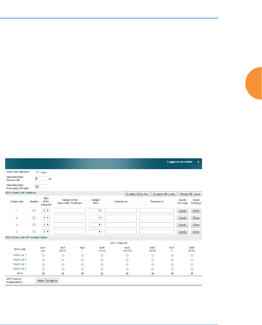
Wireless Access Point
Configuring the Wireless AP 387
Long Distance Links
If you are using WDS to provide backhaul over an extended distance, use the
WDS Dist. (Miles) setting to prevent timeout problems associated with long
transmission times. (See “IAP Settings” on page 313) Set the approximate distance
in miles between this IAP and the connected AP in the WDS Dist. (Miles)
column. This will increase the wait time for frame transmission accordingly.
See Also
SSID Management
Active IAPs
WDS Client Links
WDS Statistics
WDS Client Links
This window allows you to set up a maximum of four WDS client links.
Figure 188. WDS Client Links

Wireless Access Point
388 Configuring the Wireless AP
Procedure for Setting Up WDS Client Links
1. Host Link Stations: Check the Allow checkbox to instruct the AP to
allow stations to associate to IAPs on a host AP that participates in a WDS
link. The WDS host IAP will send beacons announcing its availability to
wireless clients. This is disabled by default.
2. Roaming RSSI Threshold: If an AP is deployed on a mobile site (on a
train, for example), you can use WDS to implement a wireless backhaul
that will roam between APs at fixed locations. When another candidate
AP for WDS host target is found, the client link will roam to the new AP if
its RSSI is stronger than the RSSI of the current host connection by at least
the Roaming RSSI Threshold. The default is 6 dB.
3. Roaming RSSI Averaging Weight: This weight changes how much the
latest RSSI reading influences the cumulative weighted RSSI value
utilized in checking the threshold (above) to make a roaming decision.
The higher the weight, the lower the influence of a new RSSI reading.
This is not exactly a percentage, but a factor in the formula for computing
the current RSSI value based on new readings:
#Once some IAP has been selected to act as a WDS client link, no other
association will be allowed on that IAP. However, wireless associations will
be allowed on the WDS host side of the WDS session.
#In situations like the one in the next step, where WDS is used by an AP
mounted on a high speed train, STP can add significant delay (often on the
order of 30 to 60 seconds) while initially analyzing network topology. In
such a situation, it may be desirable to disable STP. See “Management
Control” on page 238.
#Caution: If Spanning Tree Protocol (“Management Control” on page 238) is
disabled and a network connection is made on the WDS Client AP’s Gigabit
link that can reach the WDS Host AP, broadcast and multicast packets will
not be blocked. A broadcast storm may cause a network outage.

Wireless Access Point
Configuring the Wireless AP 389
StoredRSSI = (StoredRSSI * RoamingAvgWeight
+ NewRSSIReading * (100 - RoamingAvgWeight)) / 100
This prevents erroneous or out-of-line RSSI readings from causing the
WDS link to jump to a new AP. Such readings can result from temporary
obstructions, external interference, etc.
4. Click the Save button after you are finished making changes on this
page if you wish to make your changes permanent.
WDS Client Link Setting:
5. Enable/Disable/Reset All Links: Click the appropriate button to:
•Enable All Links—this command activates all WDS links configured
on the AP.
•Disable All Links—this command deactivates all WDS links
configured on the AP. It leaves all your settings unchanged, ready to
re-enable.
•Reset All Links—this command tears down all links configured on
the AP and sets them back to their factory defaults, effective
immediately.
6. Client Link: Shows the ID (1 to 4) of each of the four possible WDS links.
7. Enabled: Check this box if you want to enable this WDS link, or uncheck
the box to disable the link.
8. Max IAPs Allowed (1-3): Enter the maximum number of IAPs for this
link, between 1 and 3.
9. Target AP Base MAC Address: Enter the base MAC address of the target
AP (the host AP at the other side of this link). To find this MAC address,
open the WDS window on the target AP, and use This AP Address
located on the right under the Summary of WDS Host Links. To allow any
Xirrus AP to be accepted as a WDS target, enter the Xirrus OUI:
00:0f:7d:00:00:00 or 50:60:28:00:00:00 (this is useful for roaming in a
mobile deployment, as described in Step 2 on page 388).
10. Target SSID: Enter the SSID that the target AP is using.

Wireless Access Point
390 Configuring the Wireless AP
11. Username: Enter a username for this WDS link. A username and
password is required if the SSID is using PEAP for WDS authentication
from the internal RADIUS server.
12. Password: Enter a password for this WDS link.
13. Clear Settings: Click on the Clear button to reset all of the fields on this
line.
WDS Client Link IAP Assignments:
14. For each desired client link, select the IAPs that are part of that link. The
IAP channel assignments are shown in the column headers.
15. IAP Channel Assignment: Click Auto Configure to instruct the AP to
automatically determine the best channel allocation settings for each IAP
that participates in a WDS link, based on changes in the environment.
These changes are executed immediately, and are automatically applied.
See Also
SSID Management
WDS Planning
WDS
WDS Statistics
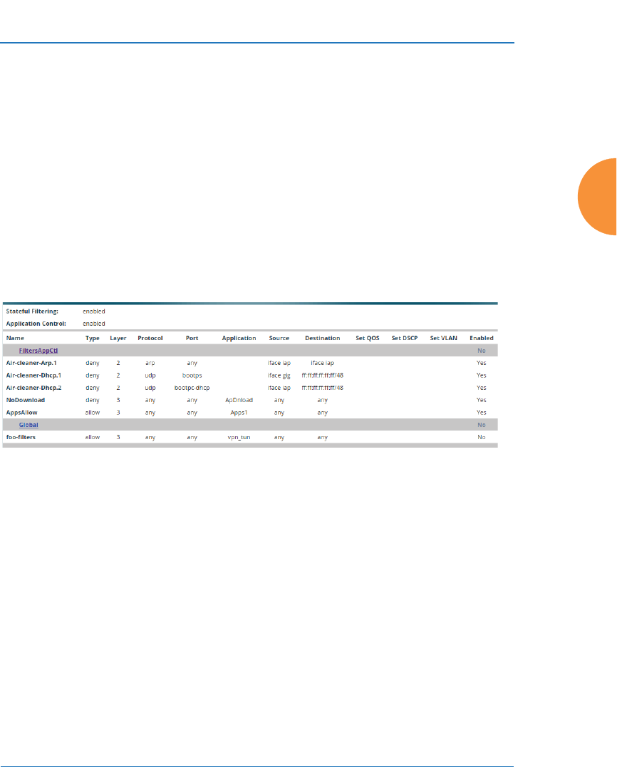
Wireless Access Point
Configuring the Wireless AP 391
Filters
The Wireless AP’s integrated firewall uses stateful inspection to speed the
decision of whether to allow or deny traffic. Filters are used to define the rules
used for blocking or passing traffic. Filters can also set the VLAN and QoS level
for selected traffic.
Filters may be used based on your experience with Application Control Windows
to eliminate or cap the amount of traffic allowed for less desirable applications.
Figure 189. Filters
User connections managed by the firewall are maintained statefully — once a user
flow is established through the AP, it is recognized and passed through without
application of all defined filtering rules. Stateful inspection runs automatically on
the AP. The rest of this section describes how to view and manage filters.
Filters are organized in groups, called Filter Lists. A filter list allows you to apply
a uniform set of filters to SSIDs or Groups very easily. Similarly, you can use a
custom Application Control list to create a set of applications that are handled as a
group for convenience when creating filters.
The read-only Filters window provides you with an overview of all filter lists and
Application Control lists that have been defined for this AP, and the filters that
have been created in each list. Filters are listed in the left side column by name
#The air cleaner feature offers a number of predetermined filter rules that
eliminate a great deal of unnecessary wireless traffic. See “Air Cleaner” on
page 468.
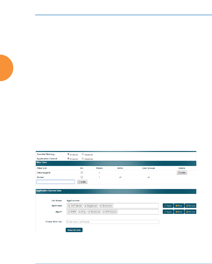
Wireless Access Point
392 Configuring the Wireless AP
under the filter list to which they belong. Each filter entry is a link that takes you
to its Filter Management entry, and the list includes information about the type of
filter, the protocol it is filtering, which port it applies to, source and destination
addresses, and QoS and VLAN assignments.
Filter Lists
This window allows you to create filter lists and custom Application Control lists.
These lists offer you ease of management of groups of filters and applications. The
AP comes with one predefined filter list, named Global, which cannot be deleted.
Filter lists (including Global) may be applied to SSIDs or to Groups. Only one
filter list at a time may be applied to a group or SSID (although the filter list may
contain a number of filters). All filters are created within filter lists.
Use a custom Application Control list to create a set of applications that may then
be handled as a group when creating filters. Thus, one filter can apply to an entire
group of applications. This keeps the number of filters down and makes them
much easier to manage. For example, you can include BitTorrent, Netflix, and Fox
Sports in an Application Control list, and then create a single filter to block all
three during business hours.
Figure 190. Filter Lists

Wireless Access Point
Configuring the Wireless AP 393
Procedure for Managing Filter Lists
1. Stateful Filtering: Stateful operation of the integrated firewall can be
Enabled or Disabled. If you have a large number of filters and you don’t
want to apply them in a stateful manner, you may use this option to turn
the firewall off.
2. Application Control: Operation of the Application Control feature may
be Enabled or Disabled. See “Application Control Windows” on
page 150.
Filter Lists
3. New Filter List Name: Enter a name for the new filter list in this field,
then click on the Create button to create the list. All new filters are
disabled when they are created. The new filter list is added to the Filter
List table in the window. Click on the filter list name, and you will be
taken to the Filter Management window for that filter list. You may create
up to 16 filter lists (up to 8 on the XR-500 Series).
4. On: Check this box to enable this filter list, or leave it blank to disable the
list. If the list is disabled, you may still add filters to it or modify it, but
none of the filters will be applied to data traffic.
5. Filters: This read-only field displays the number of filters that belong to
this filter list.
6. SSIDs: This read-only field lists the SSIDs that use this filter list.
7. User Groups: This read-only field lists the Groups that use this filter list.
8. Delete: Click this button to delete this filter list. The Global filter list may
not be deleted.
#The Application Control feature is only available if the AP license includes
Application Control. If a setting is unavailable (grayed out), then your
license does not support the feature. See “About Licensing and Upgrades”
on page 412.

Wireless Access Point
394 Configuring the Wireless AP
Custom Application Control List
9. Create New List: Enter a name for the new Application Control list in this
field, followed by the ENTER key. The new list is added to the
Application Control Lists table, and this list may be used to create filters.
You may create up to 15 lists (on the XR-520, the limits are reduced to 8
lists and 125 applications per list).
Click in the field for the new Application Control list to display a list of
applications. Add the desired applications to this list, one at a time. Up to
250 applications may be added. This field also provides a search feature—
type in a string, and the list will display only the choices whose names
contain that string in any position. Click the Apply button on the right
when done adding applications to this list.
Click Reset if you want to remove all of the entries from this field, i.e., to
empty it. Click Remove to delete this Application Control list. You may
use Reset All Lists on the bottom to delete all lists.
10. Click the Save button if you wish to make your changes permanent.
11. Click a filter list to go to the Filter Management window to create and
manage the filters that belong to this list.
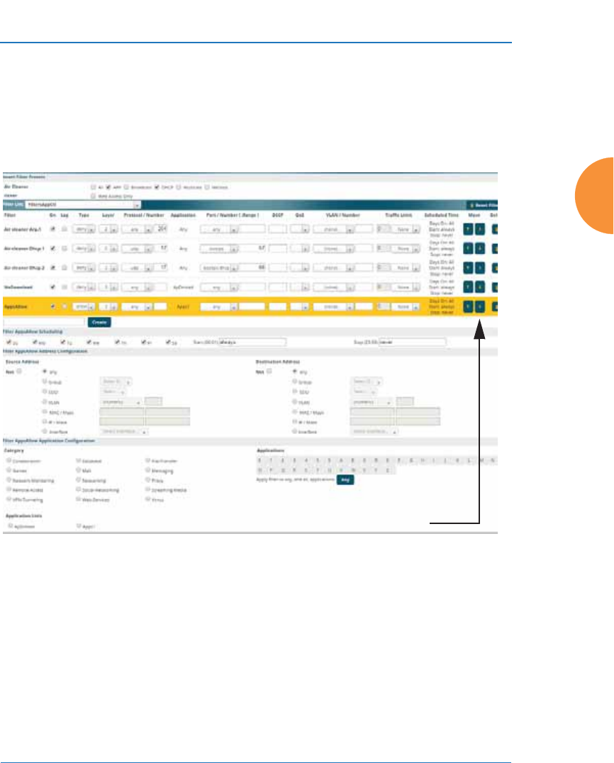
Wireless Access Point
Configuring the Wireless AP 395
Filter Management
This window allows you to create and manage filters that belong to a selected
filter list, based on the filter criteria you specify. Filters are an especially powerful
feature when combined with the intelligence provided by the “Application
Control Windows” on page 150.
Figure 191. Filter Management
Based on Application Control’s analysis of your wireless traffic, you can create
filters to enhance wireless usage for your business needs:
z
Usage of non-productive and risky applications like BitTorrent can be
restricted.
z
Traffic for mission-critical applications like VoIP and WebEx may be given
higher priority (QoS).
Filters are applied in order, from top to
bottom. Click here to change the order.

Wireless Access Point
396 Configuring the Wireless AP
z
Non- critical traffic from applications like YouTube may be given lower
priority (QoS) or bandwidth allowed may be capped per station or for all
stations.
z
Traffic flows for specific applications may be controlled by sending them
into VLANs that are designated for that type of traffic.
z
Filters may be applied at specified times—for example, no games allowed
from 8 AM to 6 PM.
Note that filtering is secondary to the stateful inspection performed by the
integrated firewall. Traffic for established connections is passed through without
the application of these filtering rules.
Procedure for Managing Filters
1. Insert Filter Presets: A number of predefined “Air Cleaner” filters are
available using these buttons. You can use these rules to eliminate a great
deal of unnecessary wireless traffic, resulting in improved performance.
Web Access Only may be selected to allow only web access protocols to
be used. For more information, please see “Air Cleaner” on page 468.
When you select one of the filter presets, the appropriate filters will be
added to the list, so that you can see exactly what settings have been
used.
2. Filter List: Select the filter list to display and manage on this window. All
of the filters already defined for this list are shown, and you may create
additional filters for this list. You may create up to 50 filters per list (up to
25 per list on the XR-500 Series).
3. Add a New Filter: To add a new filter, enter its name in the field next to
the Create button at the bottom of the filter list, then click Create. All new
filters are added to the table of filters in the window. The filter name must
be unique within the list, but it may have the same name as a filter in a
different filter list. Two filters with the same name in different filter lists
will be completely unrelated to each other — they may be defined with
different parameter values.

Wireless Access Point
Configuring the Wireless AP 397
Viewing or modifying existing filter entries:
4. Filter: Select a filter entry if you wish to modify it. Source and destination
details are displayed below the bottom of the list.
5. On: Use this field to enable or disable this filter.
6. Log: Log usage of this filter to Syslog.
7. Type: Choose whether this filter will be an Allow filter or a Deny filter. If
you define the filter as an Allow filter, then any traffic that meets the filter
criteria will be allowed. If you define the filter as a Deny filter, any traffic
that meets the filter criteria will be denied.
8. Layer: Select network layer 2 or 3 for operation of this filter.
9. Protocol/Number: Choose a specific filter protocol from the pull-down
list, or choose numeric and enter a Number, or choose any to instruct the
AP to use the best filter. This is a match criterion.
10. Application: Shows an application to filter, based on settings from Step
22 and Step 23. If an application has been selected, you should not enter
Protocol or Port—application filters have intelligence built into them, and
perform filtering that you cannot accomplish with just port and protocol.
See “Application Control Windows” on page 150.
11. Port/Number: This is a match criterion. From the pull-down list, choose
the target port type for this filter. Choose any to instruct the AP to apply
the filter to any port, or choose 1-65534 and enter a Number.
To enter a Range of port numbers, separate the start and end numbers
with a colon as shown: Start # : End #.
12. DSCP: Differentiated Services Code Point or DiffServ (DSCP) —Optional.
Set packets ingressing from the wireless network that match the filter
criteria to this DSCP level (0 to 63) before sending them out on the wired
network. Select the level from the pull-down list. Level 0 has the lowest
priority; level 63 has the highest priority. By default, this field is blank
and the filter does not modify DSCP level. See “Understanding QoS
Priority on the Wireless AP” on page 271.

Wireless Access Point
398 Configuring the Wireless AP
13. QoS: (Optional) Set packets ingressing from the wired network that
match the filter criteria to this QoS level (0 to 3) before sending them out
on the wireless network. Select the level from the pull-down list. Level 0
has the lowest priority; level 3 has the highest priority. By default, this
field is blank and the filter does not modify QoS level. See
“Understanding QoS Priority on the Wireless AP” on page 271.
14. VLAN/Number: (Optional) Set packets that match the filter criteria to
this VLAN. Select a VLAN from the pull-down list, or select numeric and
enter the number of a previously defined VLAN (see “VLANs” on
page 213).
15. Traffic Limit: Instead of simply allowing the specified traffic type, you
may cap the amount of traffic allowed that matches this filter. First choose
the units for the limit: kbps for all stations in total or per station, or
packets per second (pps) for all stations in total or per station. Then enter
the numeric limit in the field to the left.
16. Scheduled Time: shows the times at which this filter is active, if you have
established a schedule in Step 19.
17. Move Up/Down: The filters are applied in the order in which they are
displayed in the list, with filters on the top applied first. To change an
entry’s position in the list, just click its Up or Down button.
18. To delete a filter, click its Delete button.
Select an existing filter entry in the list to view or modify Scheduling or Address
Configuration, shown below the list of filters:
19. Scheduling: Use these fields if you wish to specify a scheduled time for
this filter to be active. Check the checkboxes for the days that the filter is
to be active. By default, the filter is active all day on each selected day.
You may also specify a time of day for the filter to be active by entering a
Start and Stop time in 24:00 hour format (i.e., 6:30 PM is 18:30). To use
this feature, you must enter both a Start and a Stop time.
You cannot apply one filter for two or more scheduled periods, but you
can create two filters to achieve that. For example, one filter could deny
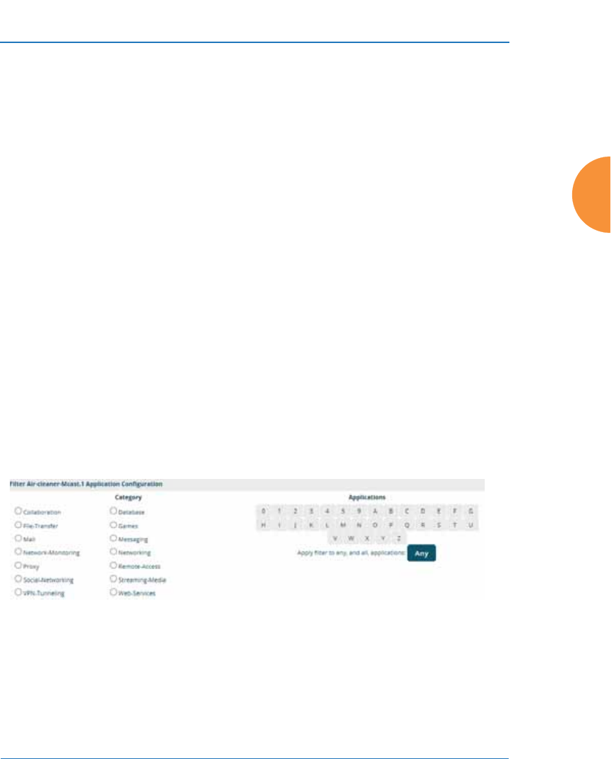
Wireless Access Point
Configuring the Wireless AP 399
the category Games from 9:00 to 12:00, and another could deny them
from 13:00 to 18:00. Similarly, you might create two rules for different
days—one to deny Games Mon-Fri 8:00 to 18:00, and another to deny
them on Sat. from 8:00 to 12:00.
20. Source Address: Define a source address to match as a filter criterion.
Click the radio button for the desired type of address (or other attribute)
to match. Then specify the value to match in the field to the right of the
button. Choose Any to use any source address. Check Not to match any
address except for the specified address.
21. Destination Address: Define a destination address to match as a filter
criterion. Click the radio button for the desired type of address (or other
attribute) to match. Then specify the value to match in the field to the
right of the button. Choose any to use any destination address. Check Not
to match any address except for the specified address.
Below the Source and Destination Addresses, you may enter a Category or an
Application or an Application List to be matched by the filter:
22. Category: If you wish this filter to apply to a particular category of
application, such as File-Transfer or Database, select it from the listed
options.
Figure 192. Filter Category or Application
23. Applications: If you wish this filter to apply to a specific application,
such as WebEx, click the letter or number that it starts with. Then select
the desired application. You may select a Category or an Application, but
not both.

Wireless Access Point
400 Configuring the Wireless AP
24. Application Lists: If you wish this filter to apply to a previously
configured Custom Application Control List, select the desired list. You
may not select a Category or an Application in addition to the list.
25. Click the Save button if you wish to make your changes permanent.
See Also
Filters
Filter Statistics
Understanding QoS Priority on the Wireless AP
VLANs
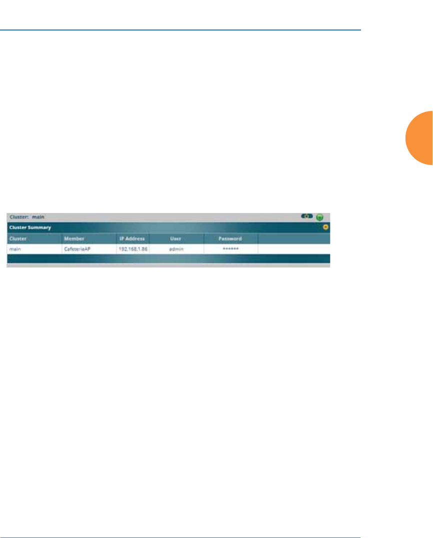
Wireless Access Point
Configuring the Wireless AP 401
Clusters
Clusters allow you to configure multiple APs at the same time. Using WMI (or
CLI), you may define a set of APs that are members of the cluster. Then you may
enter Cluster mode for a selected cluster, which sends all successive configuration
commands issued via CLI or WMI to all of the member APs. When you exit
cluster mode, configuration commands revert to applying only to the AP to which
you are connected.
The Clusters window displays a summary of defined clusters and members.
Figure 193. Clusters
Clusters are discussed in the following topics:
z
Cluster Management
Cluster Management
Clusters are displayed and managed in the single Cluster Management window.
This window allows new clusters to be created and APs to be added or removed
from clusters.
The Clusters window provides you with an overview of all clusters that have
been defined for this AP, and the APs that have been added to each. Clusters are
listed and cluster members may be displayed by expanding a cluster entry. Each
AP entry displays its IP Address, Username, and Password. All existing clusters
#An XR-500 or XR-1000 Series AP cannot act as the Cluster controller. It
will operate correctly as a member of a cluster.
#An XR-500 or XR-1000 Series AP cannot act as the Cluster controller. It
will operate correctly as a member of a cluster.
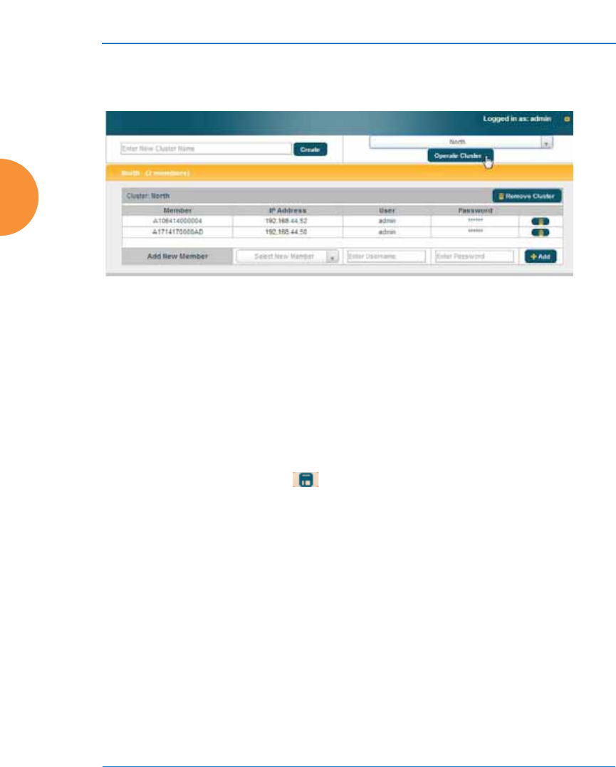
Wireless Access Point
402 Configuring the Wireless AP
are shown, along with the number of APs currently in each. Up to 16 clusters may
be created, with up to 50 APs in each.
Figure 194. Cluster Management
Procedure for Managing Cluster Definition
1. New Cluster Name: Enter a name for the new cluster in the field to the
left of the Create button, then click Create to add this entry. The new
cluster is added to the list in the window.
2. Delete: To delete a cluster, expand the entry for the cluster and click its
Remove Cluster button.
3. Click the Save button if you wish to make your changes permanent.
4. Expand the entry for a cluster to add or remove APs in the cluster.

Wireless Access Point
Configuring the Wireless AP 403
Note that the AP on which you are currently running WMI is not automatically a
member of the cluster. If you would like it to be a member, you must add it
explicitly.
Procedure for Managing Clusters
1. Edit Cluster: Expand the entry for the cluster to be managed. All of the
APs already defined for this cluster are shown, and you may add
additional APs to this list.
2. Add New Member: Select a new cluster member from the Select New
Member drop-down list. This list shows Arrays/APs that are accessible
to this AP for management purposes.
3. User/Password: In these columns, enter the administrator name and
password for access to the AP.
4. Click the +Add button to enter the AP.
5. To delete an AP, click its button.
6. Click the Save button if you wish to make your changes permanent.
In Cluster Mode, all configuration operations that you execute in WMI or CLI are
performed on the members of the cluster. They are not performed on the AP
where you are running WMI, unless it is a member of the cluster.
You must use the Save button at the top of configuration windows to
permanently save your changes in Cluster Mode, just as you would in normal
operation. When you are done configuring APs in the cluster, return to this
window and click the button to leave Cluster Mode.
Procedure for Operating in Cluster Mode
1. Operate: Select a defined cluster from the menu to the left of the Operate
Cluster button and then click on the Operate Cluster button.
2. Select a WMI page for settings that you wish to configure for the cluster,
and proceed to make the desired changes.
3. Proceed to any additional pages where you wish to make changes.
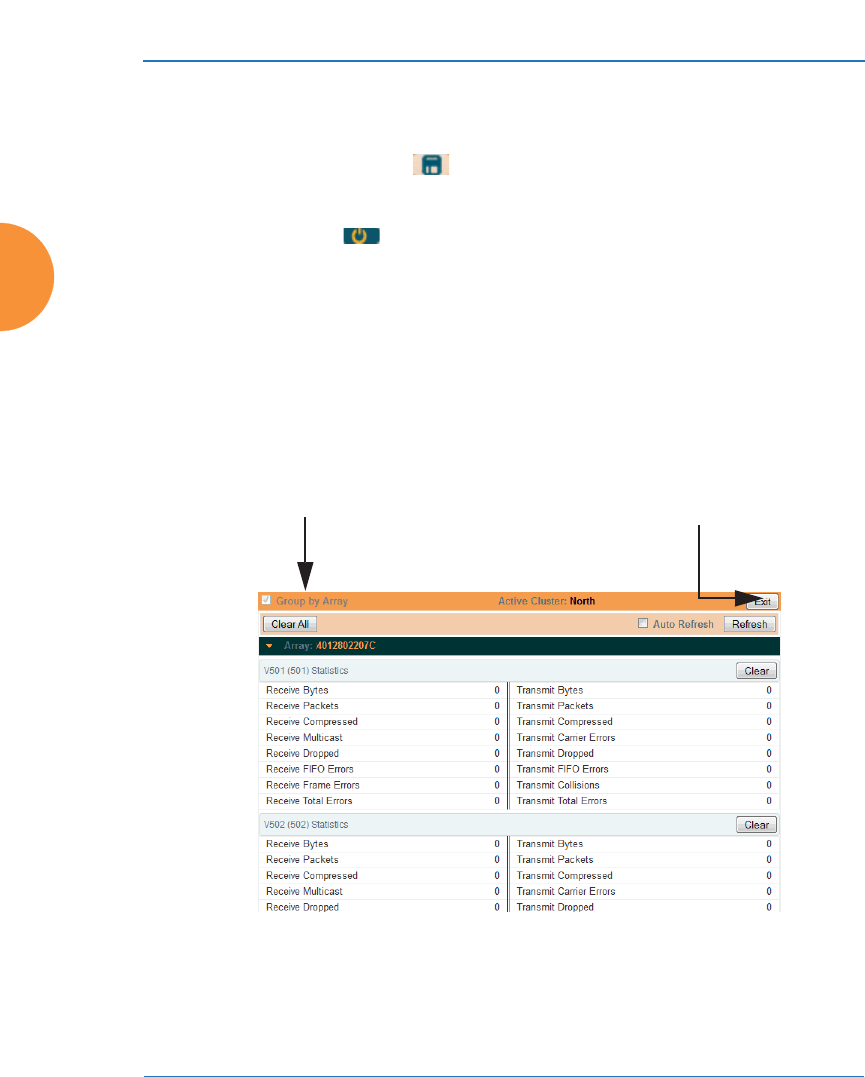
Wireless Access Point
404 Configuring the Wireless AP
4. Some Status and Statistics windows will present information for all APs
in the cluster.
5. Click the Save button when done if you wish to save changes on the
cluster member APs.
6. Exit: Click the button to the right of the operating cluster to terminate
Cluster Mode. The WMI returns to normal operation — managing only
the AP to which it is connected.
Status and Statistics Windows in Cluster Mode
In Cluster Mode, many of the Status and Statistics windows will display
information for all of the members of the cluster. You can tell whether a window
displays cluster information — if so, it will display the Cluster Name near the top,
as shown in Figure 195.
Figure 195. Viewing Statistics in Cluster Mode
You have the option to show aggregate information for the cluster members, or
click the Group by AP check box to separate it out for each AP.
Cluster Name Exit Cluster Mode

Wireless Access Point
Configuring the Wireless AP 405
You may terminate cluster mode operation by clicking the button to the right
of the row.
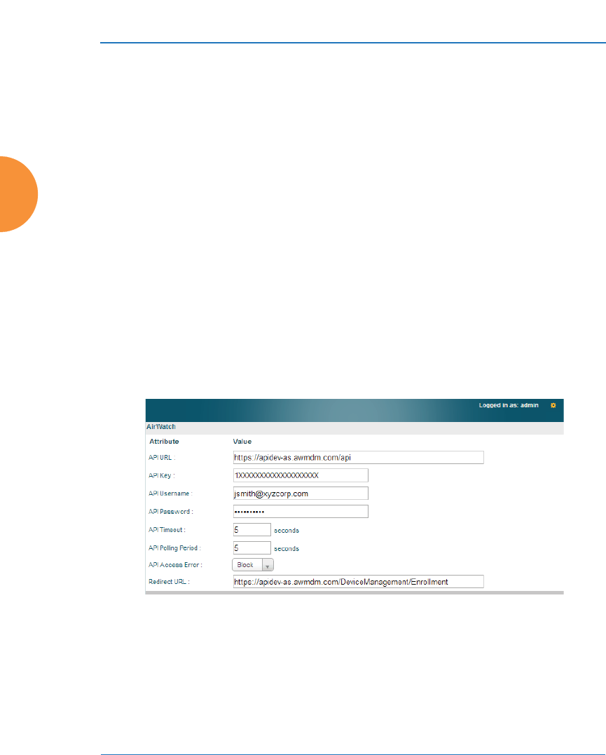
Wireless Access Point
406 Configuring the Wireless AP
Mobile
Mobile Device Management (MDM) servers enable you to manage large-scale
deployments of mobile devices. They may include capabilities to handle tasks
such as enrolling devices in your environment, configuring and updating device
settings over-the-air, enforcing security policies and compliance, securing mobile
access to your resources, and remotely locking and wiping managed devices.
Xirrus APs support the AirWatch MDM, using an AirWatch API call to determine
the status of a user’s device and allow access to the wireless network only if the
device is enrolled and compliant with the policies of the service.
AirWatch
Individual SSIDs may be configured to require AirWatch enrollment and
compliance before a mobile device such as a smartphone or tablet is admitted to
the wireless network. The AP uses the AirWatch API with the settings below to
request that AirWatch check whether the mobile device is enrolled and compliant
with your wireless policies.
Figure 196. AirWatch Settings
Before configuring AirWatch settings on the AP, you must have an AirWatch
account, already set up with your organization’s compliance policies and other
configuration as required by AirWatch.

Wireless Access Point
Configuring the Wireless AP 407
The AP settings entered on this page are mostly taken from AirWatch. Once you
have entered these settings, your users will be constrained to follow a set of steps
to access the wireless network, as described in “User Procedure for Wireless
Access” on page 408.
Procedure for Managing AirWatch
If you have configured the Mobile Device Management setting on one or more
SSIDs to use AirWatch, then the API specified below will be used to determine
the admissibility of a mobile device requesting a connection to the wireless
network.
1. API URL: Obtain this from your AirWatch server’s System / Advanced /
Site URLs page. Copy the REST API URL string into this field. This
specifies the AirWatch API that the AP will call to determine the
enrollment and compliance status of a mobile device attempting to
connect to the AP. The steps that the user will need to take are described
in “User Procedure for Wireless Access” on page 408.
2. API Key: Obtain this from your AirWatch server. Go to the System /
Advanced / API / REST page, General tab, and copy the API Key string
into this field. The key is required for access to the API.
3. API Username: Enter the user name for your account on the AirWatch
server.
4. API Password: Enter the password for your account on the AirWatch
server.
5. API Timeout: (seconds) If AirWatch does not respond within this many
seconds, the request fails.
6. API Polling Period: (seconds) Mobile device enrollment and compliance
status will be checked via polling at this interval. Note that there may
thus be a delay before the mobile device will be admitted.
7. API Access Error: Specify whether or not to allow access if AirWatch fails
to respond. The default is to Block access.

Wireless Access Point
408 Configuring the Wireless AP
8. Redirect URL: Obtain this from your AirWatch server. Go to the System /
Advanced / Site URLs page, and copy the Enrollment URL string into
this field. When a mobile device that is not currently enrolled with
AirWatch attempts to connect to the AP, the device displays a page
directing the user to install the AirWatch agent and go to the AirWatch
enrollment page. Note that Android devices will need another form of
network access (i.e. cellular) to download the agent, since un-enrolled
devices will not have access to download it via the AP. See “User
Procedure for Wireless Access” on page 408 for more details.
9. You must configure the Mobile Device Management setting on one or
more SSIDs to use AirWatch, as described in Procedure for Managing
SSIDs (see Step 17 on page 283).
User Procedure for Wireless Access
1. A user attempts to connect a mobile device to an SSID that uses AirWatch.
2. The device will authenticate according to the SSID’s authentication
settings (Open, Radius MAC, 802.1x).
3. The user browses to any destination on the Internet.
The AP asks the user to wait while it checks device enrollment and
compliance status by querying the AirWatch API with the device MAC
address.
4. If AirWatch responds that the device is enrolled and compliant, the
device will be allowed into the network. The device will be considered
compliant if AirWatch finds that the device does not violate any
applicable policies for that device. (If no policies are assigned to the
device in AirWatch, then the device is compliant by default.)
#Device enrollment and compliance status will be checked via polling so there
may be a delay before the device will be allowed in. That delay will depend on
the API Polling Period setting.

Wireless Access Point
Configuring the Wireless AP 409
5. If the device is not enrolled, all user traffic will be blocked, except that
HTTP traffic is redirected to an intermediate page on the AP that tells the
user to download and install the AirWatch agent. The page displays a
link to the AirWatch-provided device enrollment URL. This link is a pass-
though that allows the user to go through the enrollment process. The
user will need to enter your organization’s AirWatch Group ID and
individual account credentials when requested.
Once the agent is installed, the user must start again at Step 1.
6. If the device is enrolled with AirWatch but not compliant with applicable
policies, all traffic will be blocked as in Step 5 above, and the HTTP traffic
will be redirected to an intermediate page on the AP that tells the user
which policies are out of compliance.
This page contains a button for the user to click when the compliance
issues have been corrected. This button causes AirWatch to again check
device compliance. The user's browser is redirected to a “wait” page until
the AP has confirmed compliance with AirWatch. The user’s browser is
then redirected to a page announcing that the device is now allowed
network access.
If the AP is unable to access AirWatch to obtain enrollment and compliance status
(for example, due to bad credentials, timeout, etc.), device access to the network
will be granted according to the API Access Error setting (Allow or Block). If this
field is set to Block, traffic will be blocked as in Step 5 above and HTTP traffic will
be redirected to an informational page that informs the user that AirWatch cannot
be contacted at this time and advises the user to contact the network
administrator. If this field is set to Allow, then the device will be allowed network
access.
#Android devices must go to the PlayStore to install the agent BEFORE they
can go through the enrollment process. This means un-enrolled devices need
another form of network access (i.e., cellular or an unrestricted SSID) to
download this agent, as they are not permitted access to the PlayStore.
Once the agent is installed, the user must start again at Step 1.

Wireless Access Point
410 Configuring the Wireless AP

Wireless Access Point
Using Tools on the Wireless AP 411
Using Tools on the Wireless AP
These WMI windows allow you to perform administrative tasks on your AP, such
as upgrading software, rebooting, uploading and downloading configuration
files, and other utility tasks. Tools are described in the following sections:
z
“System Tools” on page 412
z
“CLI” on page 426
z
“API Documentation” on page 428
z
“Options” on page 433
z
“Logout” on page 434
This section does not discuss using status or configuration windows. For
information on those windows, please see:
z
“Viewing Status on the Wireless AP” on page 95
z
“Configuring the Wireless AP” on page 161
#If you have added modular IAPs to your AP, note that its model number will
be automatically adjusted to reflect the count and types of IAPs currently
installed. See Upgrading with 802.11ac radio modules.
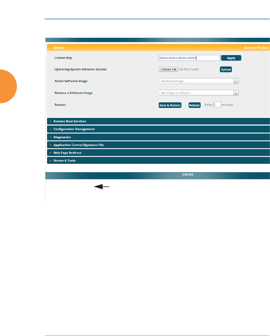
Wireless Access Point
412 Using Tools on the Wireless AP
System Tools
Figure 197. System Tools
This window allows you to manage files for software images, configuration, and
Web Page Redirect (WPR), manage the system’s configuration parameters, reboot
the system, and use diagnostic tools. The page contains a number of sections that
you may expand.
About Licensing and Upgrades
If you are a customer using XMS, when you upgrade an AP using XMS, your
license will automatically be updated for you first.
The AP’s license determines some of the features that are available on the AP. For
example, the Application Control feature is an option that must be separately
licensed. To check the features supported by your license, see “Access Point
Information” on page 102.
Status is
shown here

Wireless Access Point
Using Tools on the Wireless AP 413
When upgrading the AP for a new major release, the AP needs the new license
key that enables the operation of that release before upgrading. If you do not
obtain the new license first, the AP will display a message and revert to the
previous software image, rather than trying to run new software for which it is
not licensed. Major releases will need a new license key, but minor releases will
not. For example, to upgrade from ArrayOS Release 7.0.5 to Release 7.1, you must
enter a new license key. To upgrade from ArrayOS Release 7.0.1 to Release 7.0.3,
use your existing license key.
If you are not using XMS to perform a software upgrade, you may use the Auto-
provisioning Start button to get an updated license from Xirrus before
performing an upgrade. See “Configuration Management” on page 417.
If you will be entering license keys and performing upgrades on many APs, the
effort will be streamlined by using the Xirrus Management System (XMS),
especially if you are using XMS Cloud.
Procedure for Configuring System Tools
These tools are broken down into the following sections:
z
System
z
Remote Boot Services
z
Configuration Management
z
Diagnostics
z
Application Control Signature File Management
z
Web Page Redirect (Captive Portal)
z
Network Tools
z
Progress Bar and Status Frame

Wireless Access Point
414 Using Tools on the Wireless AP
System
Note that the top line of this section shows the current software version running
on the AP. See Figure 197.
1. License Key
If you need an updated license (for example, if you are upgrading an AP
to a new major release—say, from 7.0 to 7.1, and you are not using XMS to
perform network-wide updates), you may obtain one through Auto-
provisioning. See “Configuration Management” on page 417.
If you need to enter a new license key manually, use the License Key field
to enter it, then click the Apply button to the right.
A valid license is required for AP operation, and it controls the features
available on the AP. If you upgrade your AP for additional features, you
will be provided with a license key to activate those capabilities.
A license update will automatically save a copy of the current
configuration of the AP. See Step 3 on page 418.
If you attempt to enter an invalid key, you will receive an error message
and the current key will not be replaced.
Operating System Software Upload: This feature upgrades the ArrayOS
to a newer version provided by Xirrus. Please note that you typically
will need an updated license key to cover the upgrade’s features before
clicking the Upgrade button. For customers using XMS-Cloud, your
#If you are a customer using XMS-Cloud, your license will be updated for
you automatically; with other XMS versions, you can easily upgrade all
members of a profile network to a new ArrayOS release, including updating
license keys.
#Trial licenses: If you enter a trial license to try new premium features, then
when the trial expires the perpetual license will be restored automatically
without requiring a reboot. When the trial expires, the current AP
configuration will not be lost.

Wireless Access Point
Using Tools on the Wireless AP 415
license will be updated for you automatically; with other XMS versions,
you can easily upgrade all members of a profile network to a new
ArrayOS release. See “About Licensing and Upgrades” on page 412 for
details. Click the Choose File button to locate the software upgrade file,
then click on the Upload button to upload the new file to the AP. Progress
of the operation will be displayed in a progress bar. Completion status of
the operation is shown in the Status section.
This operation does not run the new software or change any configured
values. The existing software continues to run on the AP until you reboot,
at which time the uploaded software will be used. An upgrade will,
however, automatically save a copy of the current configuration of the
AP. See Step 3 on page 418.
2. Active Software Image: Use the Set Active Image drop-down list to
display all of the software versions that are on your AP. Select the version
from the list that you would like to become the active version the next
time that you reboot.
3. Remove a Software Image: Use the Set Image to remove drop-down list
to display all of the software versions that are on your AP. Select a
version from the list to remove it. Note that there is no Apply button for
this—the image is removed with no further action on your part.
4. Save & Reboot or Reboot: Use Save & Reboot to save the current
configuration and then reboot the AP. The AP will reboot using the
software version that you have selected in Active Software Image, above.
The LEDs on the AP indicate the progress of the reboot, as described in
“Powering Up the Wireless AP” on page 72. Alternatively, use the Reboot
#If you have difficulty upgrading the AP using the WMI, see “Upgrading
the AP Using the Boot Loader” on page 537 for a lower-level procedure
you may use.
Software Upgrade always uploads the file in binary mode. If you transfer
any image file to your computer to have it available for the Software Upgrade
command, it is critical to remember to transfer it (ftp, tftp) in binary mode!
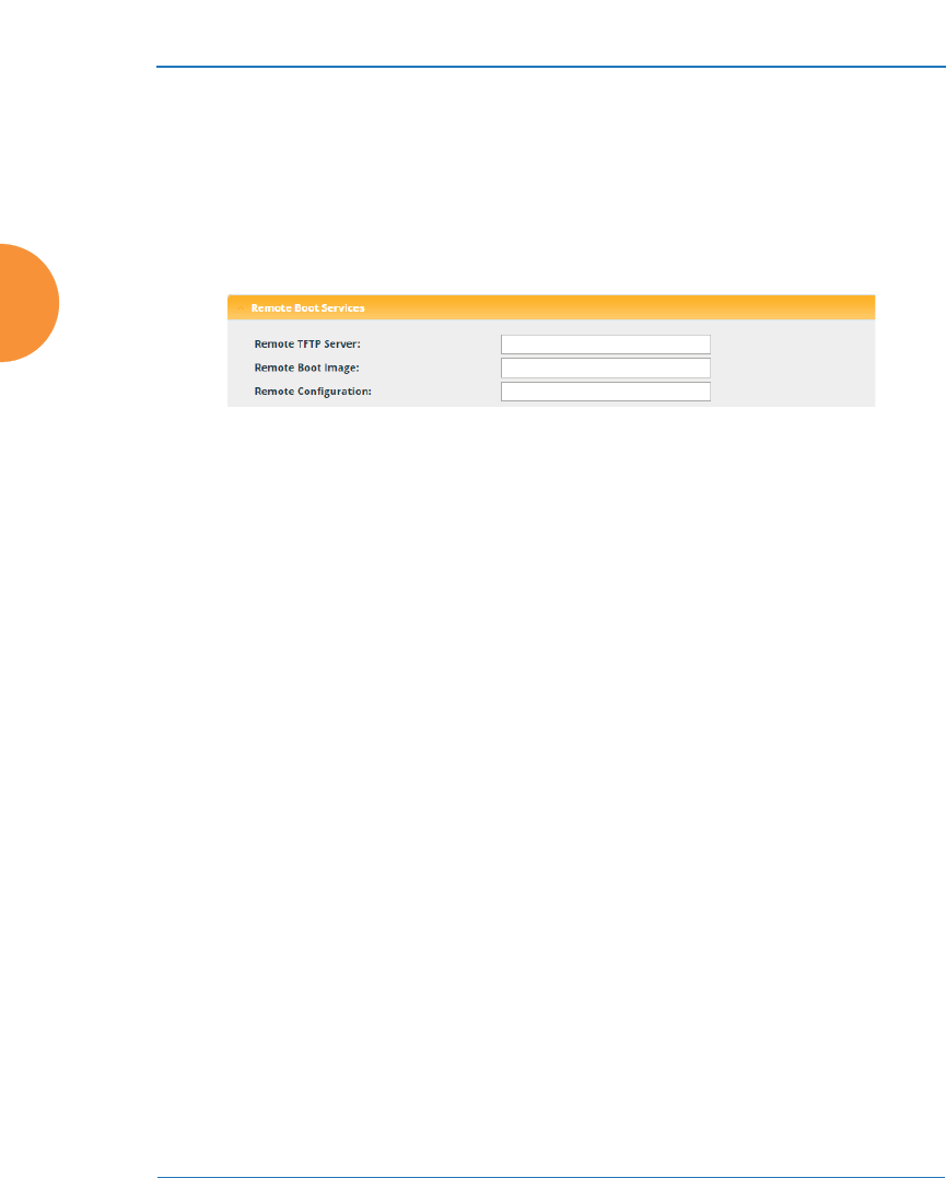
Wireless Access Point
416 Using Tools on the Wireless AP
button to discard any configuration changes which have not been saved
since the last reboot. You may specify an optional Delay period in
seconds to wait before the reboot starts.
Remote Boot Services
(Automatic updates from remote image or configuration file)
Figure 198. Remote Boot Services
The AP software image or configuration file can be downloaded from an external
server. In large deployments, all APs can be pointed to one TFTP server instead of
explicitly initiating software image uploads to all APs. When the AP boots, the AP
will download the software image from the specified TFTP server. Similarly, if
you decide to change a setting in the APs, you can simply modify a single
configuration file. After the APs are rebooted, they will automatically download
the new configuration file from a single location on the specified TFTP server.
1. Remote TFTP Server: This field defines the path to a TFTP server to be
used for automated remote update of software image and configuration
files when rebooting. You may specify the server using an IP address or
host name.
2. Remote Boot Image: When the AP boots up, it fetches the software image
file specified here from the TFTP server defined above, and upgrades to
this image before booting. This must be an AP image file with a .bin
extension.
Make sure to place the file on the TFTP server. If you disable the remote
boot image (by blanking out this field) or if the image can't be transferred,
the AP will fall back to booting whatever image is on the compact flash.
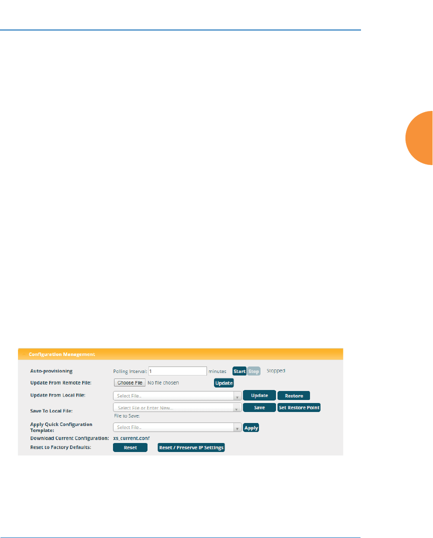
Wireless Access Point
Using Tools on the Wireless AP 417
3. Remote Configuration: When the AP boots up, it fetches the specified
configuration file from the TFTP server defined above, and applies this
configuration after the local configuration is applied. The remote
configuration must be an AP configuration file with a .conf extension.
Make sure to place the file on the TFTP server.
A partial configuration file may be used. For instance, if you wish to use a
single configuration file for all of your APs but don't want to have the
same IP address for each AP, you may remove the ipaddr line from the
file. You can then load the file on each AP and the local IP addresses will
not change.
A remote configuration is never saved to the compact flash unless you
issue a Save command.
Configuration Management
Figure 199. Configuration Management
1. If you need an updated license (for example, if you are upgrading an AP
to a new major release—say, from 7.0 to 7.1, and you are not using XMS to
#The Remote Boot Image or Remote Configuration update happens every time
that the AP reboots. If you only want to fetch the remote image or
configuration file one time, be sure to turn off the remote option (blank out
the field on the System Tools page) after the initial download. When a remote
boot image is used, the image is transferred directly into memory and is
never written to the compact flash.

Wireless Access Point
418 Using Tools on the Wireless AP
perform network-wide updates), you may obtain one through Auto-
provisioning. Click the Start button, and the AP will contact the Xirrus
server with its serial number and MAC address to obtain and install its
latest license. If the AP is unable to access the activation server, it will
continue to attempt to contact the server at intervals specified by the
Polling Interval (the default value is one minute). Click the Stop button if
you wish to stop contacting the server.
2. Update from Remote File: This field allows you to define the path to a
configuration file (one that you previously saved — see Step 4 and Step 6
below). Click on the Browse button if you need to browse for the location
of the file, then click Update to update your configuration settings.
3. Update from Local File: This field updates AP settings from a local
configuration file on the AP. Select one of the following files from the
drop-down list:
•factory.conf: The factory default settings.
•lastboot.conf: The setting values from just before the last reboot.
•saved.conf: The last settings that were explicitly saved using the Save
button at the top of each window.
•history/saved-yyyymmdd-pre-update.conf:
history/saved-yyyymmdd-post-update.conf:
Two files are automatically saved for a software upgrade or for a
license change (including the setting values from just before the
upgrade/change was performed, and the initial values afterward.
The filename includes the date.
•history/saved-yyyymmdd-auto.conf: Each time you use the Save
button, an “auto” file is saved with the settings current at that time.
•history/saved-yyyymmdd-pre-reset.conf:
history/saved-yyyymmdd-post-reset.conf:
Each time you use one of the Reset to Factory Default buttons, two
files are saved: the setting values from just before the reset, and the
initial values afterward. The filename includes the reset date.

Wireless Access Point
Using Tools on the Wireless AP 419
•history/saved-yyyymmdd-hhmm.conf: The setting values that were
explicitly saved using the Set Restore Point button (see Step 4
below).
Click Update to update your configuration settings by appending to the
current AP configuration. Click Restore to replace the AP configuration
with the configuration file selected.
Note that the History folder allows a maximum of 16 files. The oldest file
is automatically deleted to make room for each new file.
4. Save to Local File: There are a few options for explicitly requesting the
AP to save your current configuration to a file on the AP:
•To view the list of configuration files currently on the AP, click the
down arrow to the right of this field. If you wish to replace one of
these files (i.e., save the current configuration under an existing file
name), select the file, then click Save. Note that you cannot save to
the file names factory.conf, lastboot.conf, and saved.conf - these files
are write-protected.
•You may enter the desired file name, then click Save.
•Click Set Restore Point to save a copy of the current configuration,
basing the file name on the current date and time. For example:
history/saved-20100318-1842.conf
Note that the configuration is automatically saved to a file in a few
situations, as described in Step 3 above.
5. Apply Quick Configuration Template: This offers predefined
configuration options such as Classroom and High-Density that capture
best practices from years of field experience. If one of the options in the
drop-down list is appropriate to your deployment, select it and click
#Important! When you have initially configured your AP, or have made
significant changes to its configuration, we strongly recommend that you
save the configuration to a file in order to have a safe backup of your working
configuration.

Wireless Access Point
420 Using Tools on the Wireless AP
Apply. For example, the High-Density option uses best practices to
configure the AP for high density settings such as lecture halls,
convention centers, stadiums, etc.
6. Download Current Configuration: Click on the link titled
xs_current.conf to download the AP’s current configuration settings to a
file (that you can upload back to the AP at a later date). The system will
prompt you for a destination for the file. The file will contain the AP’s
current configuration values.
7. Reset to Factory Defaults: Click on the Reset/Preserve IP Settings button
to reset the system’s current configuration settings to the factory default
values, except for the AP’s management IP address which is left unchanged.
This function allows you to maintain management connectivity to the AP
even after the reset. This will retain the Gigabit Ethernet port’s IP address
(see “Interfaces” on page 170), or if you have configured management
over a VLAN it will maintain the management VLAN’s IP address (see
“VLAN Management” on page 216). All other previous configuration
settings will be lost.
Click Reset to reset all of the system’s current configuration settings to
the factory default values, including the management IP address — all
previous configuration settings will be lost. The AP’s Gigabit Ethernet ports
default to using DHCP to obtain an IP address.
#If the IP settings change, the connection to the WMI may be lost.
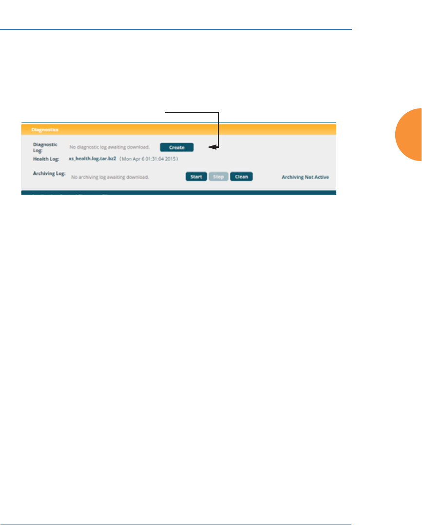
Wireless Access Point
Using Tools on the Wireless AP 421
Diagnostics
8. Diagnostic Log: Click the Create button to update the AP information for
use by Xirrus Customer Support personnel. The name of the log file ends
with diagnostic.log, and may have an additional prefix. (Figure 200)
Figure 200. Saving the Diagnostic Log
This feature is only used at the request of Customer Support. It saves all
of the information regarding your AP, including status, configuration,
statistics, log files, and recently performed actions.
The diagnostic log is always saved on your C:\ drive, so you should
immediately rename the file to save it. This way, it will not be lost the next
time you save a diagnostic log. Often, Customer Support will instruct you
to save two diagnostic logs about ten minutes apart so that they can
examine the difference in statistics between the two snapshots (for
example, to see traffic and error statistics for the interval). Thus, you must
rename the first diagnostic log file.
9. Health Log: This file is created automatically, but only if the AP
encounters unexpected and serious problems. Normally this file will not
exist. The Diagnostic Log Update button has no effect on this file
whatsoever. When a health log exists, the filename xs_health.log.bz2 is
displayed in blue and provides a link to the log file. Click the link to
download this file or to open it with your choice of application. This file is
normally only used at the request of Customer Support.
#All passwords are stored on the AP in an encrypted form and will not be
exposed in the diagnostic log.
Click Create to update log

Wireless Access Point
422 Using Tools on the Wireless AP
10. Archiving Log: This log saves internal status information that may be
needed by Xirrus Customer Support personnel. Click the Start button to
start accumulating this information. The size of the file is self-limiting so
that you do not need to be concerned about it consuming too much
storage space. Click the Stop button to stop accumulating data and make
it available in a tar file, named engineeringlogs_<hostname>.tar. A
link to this tar file appears. Click it to download the file. If you wish to
click the Start button again to accumulate data for a later time interval,
you should first download and rename the current file before it gets
overwritten.
You may use the Clear button to remove the tar file and all temporary
data from the AP’s memory.
This feature should only used at the request of Customer Support.
Application Control Signature File Management
Application Control recognizes applications using a file containing the
signatures of hundreds of applications. This file may be updated regularly to
keep up as Internet usage evolves over time. The latest signature file is
available from the same location that you use to download the latest ArrayOS
release: ArrayOS - XR Platform Latest Release. Note that new ArrayOS
releases will automatically contain the latest signature file available at the
time of the build.
See “Application Control Windows” on page 150 for more information about
using Application Control.
Figure 201. Managing Application Control Signature files

Wireless Access Point
Using Tools on the Wireless AP 423
11. Upload Signature File: First, download the latest signature file from the
Xirrus Customer Support site: ArrayOS - XR Platform Latest Release to
your file system. Click the Browse button, then browse to locate the new
signature file. Click the Upload button when it appears. The new file will
be uploaded to the AP and will be used for identifying applications. You
must turn Application Control off and back on again on the Filter Lists
page to make the new signature file take effect. See “Filter Lists” on
page 392. No reboot is required.
Active Signature File shows which file is currently being used by
Application Control. If you have installed any custom DPI signature files,
you may use Manage Signature Files.
Web Page Redirect (Captive Portal)
The AP uses a Perl script and a cascading style sheet to define the default
splash/login Web page that the AP delivers for WPR. You may replace these
files with files for one or more custom pages of your own. See Step 14 below
to view the default files. See Step 15 page 283 for more information about
WPR and how the splash/login page is used.
Each SSID that has WPR enabled may have its own page. Custom files for a
specific SSID must be named based on the SSID name. For example, if the
SSID is named Public, the default wpr.pl and hs.css files should be
modified as desired and renamed to wpr-Public.pl and hs-Public.css
before uploading to the AP. If you modify and upload files named wpr.pl
and hs.css, they will replace the factory default files and will be used for any
SSID that does not have its own custom files, per the naming convention just
described. Be careful not to replace the default files unintentionally.
Figure 202. Managing WPR Splash/Login page files
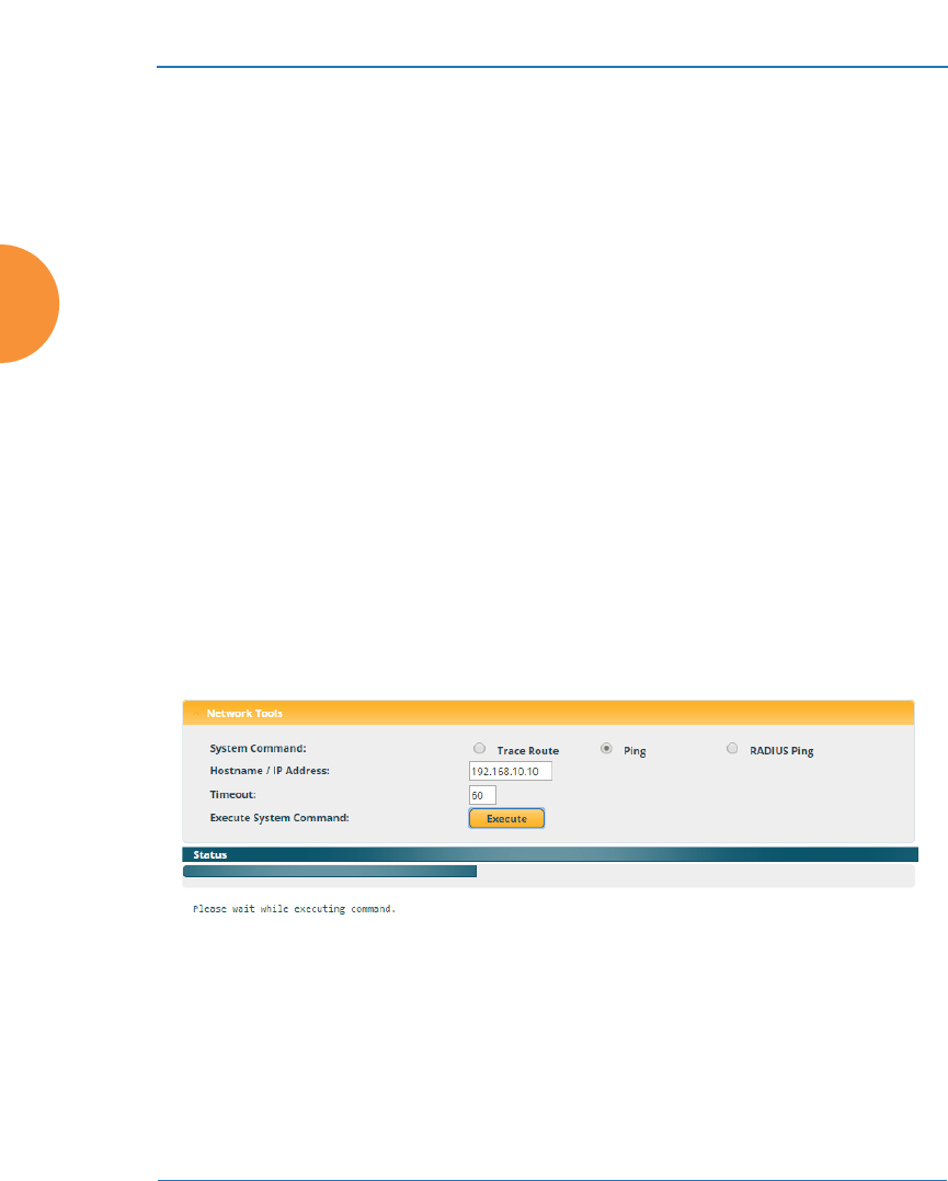
Wireless Access Point
424 Using Tools on the Wireless AP
12. Upload File: Use this to install files for your own custom WPR splash/
login page (as described above) on the AP. Note that uploaded files are
not immediately used - you must reboot the AP first. At that time, the AP
looks for and uses these files, if found.
Click Choose File to locate the splash/login page files, then click on the
Upload button to upload the new files to the AP. You must reboot to
make your changes take effect.
13. Remove File: Enter the name of the WPR file you want to remove, then
click on the Delete button. You can use the List Files button to show you
a list of files that have been saved on the AP for WPR. The list is
displayed in the Status section at the bottom of the WMI window. You
must reboot to make your changes take effect.
14. Download Sample Files: Click on a link to access the corresponding
sample WPR files:
•wpr.pl — a sample Perl script.
•hs.css — a sample cascading style sheet.
Network Tools
Figure 203. System Command (Ping)
15. System Command: Choose Trace Route, Ping., or RADIUS Ping. For
Trace Route and Ping, fill in IP Address and Timeout. Then click the
Execute button to run the command.
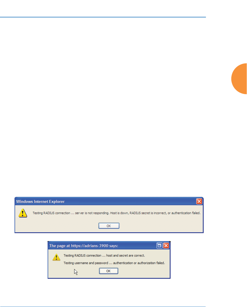
Wireless Access Point
Using Tools on the Wireless AP 425
The RADIUS Ping command is a simple utility that tests connectivity to a
RADIUS server by attempting to log in with the specified Username and
Password. When using a RADIUS server, this command allows you to
verify that the server configuration is correct and whether a particular
Username and Password are set up properly. If a client is having trouble
accessing the network, you can quickly determine if there is a basic
RADIUS problem by using the RADIUS Ping tool. For example, in
Figure 204 (A), RADIUS Ping is unable to contact the server. In Figure 204
(B), RADIUS Ping verifies that the host information and secret for a
RADIUS server are correct, but that the user account information is not.
Select RADIUS allows you to select a RADIUS server that you have
already configured. When you make a choice in this field, additional
fields will be displayed. Set Select RADIUS to External Radius, Internal
Radius, or a server specified for a particular SSID, or select Other Server
to specify another server by entering its Host name or IP address, Port,
and shared Secret.
Enter the RADIUS Credentials: Username and Password. Select the
Authentication Type, PAP or CHAP. Click the Execute button to run the
command. The message Testing RADIUS connection appears. Click OK
to proceed.
Figure 204. Radius Ping Output
A
B
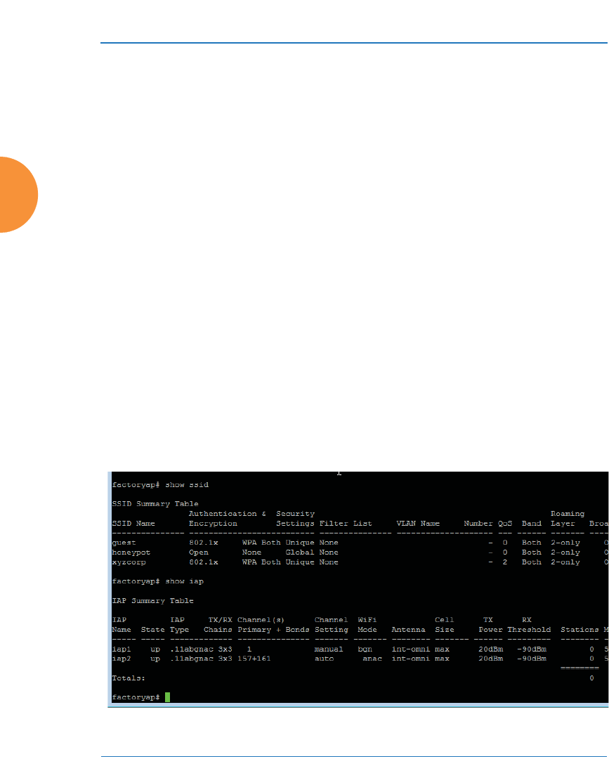
Wireless Access Point
426 Using Tools on the Wireless AP
16. IP Address: For Ping or Trace Route, enter the IP address of the target
device.
17. Timeout: For Ping or Trace Route, enter a value (in seconds) before the
action times out.
18. Execute System Command: Click Execute to start the specified
command. Progress of command execution is displayed in the Progress
frame. Results are displayed in the Status frame.
Progress Bar and Status Frame
The Progress bar is displayed for commands such as Software Upgrade and
Ping. The Status frame presents the output from system commands (Ping and
Trace Route), as well as other information, such as the results of software
upgrade.
CLI
The WMI provides this window to allow you to use the AP’s Command Line
Interface (CLI). You can enter commands to configure the AP, or display
information using show commands. You will not need to log in - you already
logged in to the AP when you started the WMI.
Figure 205. CLI Window

Wireless Access Point
Using Tools on the Wireless AP 427
To enter a command, simply type it in. The command is echoed and output is
shown in the normal way — that is, the same way it would be if you were using
the CLI directly. You may use the extra scroll bar inside the right edge of the
window to scroll through your output. If output runs past the right edge of the
screen, there is also a horizontal scroll bar at the bottom of the page.
This window has some minor differences, compared to direct use of the CLI via
the console or an SSH connection:
z
The CLI starts in config mode. All configuration and show commands are
available in this mode. You can “drill down” the mode further in the
usual way. For example, you can type interface iap to change the mode to
config-iap. The prompt will indicate the current command mode, for
example:
My-AP(config-iap) #
z
You can abbreviate a command and it will be executed if you have typed
enough of the command to be unambiguous. The command will not
auto-complete, however. Only the abbreviated command that you
actually typed will be shown. You can type a partial command and press
Tab to have the command auto-complete. If the partial command is
ambiguous a list of legal endings is displayed.
z
Entering quit will return you to the previously viewed WMI page.
z
Most, but not all, CLI commands can be run in this window. Specifically
the run-test menu of commands is not available in this window. To use
the run-test command, please connect using SSH and use CLI directly, or
use the System Tools described in this chapter, such as Trace Route, Ping,
and RADIUS Ping.
Help commands (the ? character) are available, either at the prompt or after you
have typed part of a command.
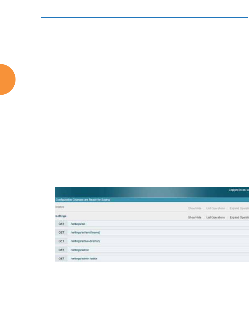
Wireless Access Point
428 Using Tools on the Wireless AP
API Documentation
APs provide an API interface conforming to the RESTful API model. Developers
may use this read-only API to read status, statistics, and settings from the AP. The
interactive API Documentation page provides documentation for the API.
You may use the AP’s API for purposes such as integrating with third party
applications or creating your own applications for network monitoring and
analysis. Using the RESTful API eliminates the need to use CLI scripting, or to use
SNMP which can be cumbersome for polling large amounts of data. Results are
returned in JavaScript Object Notation (JSON) format, a text-based open standard
designed for human-readable data interchange. The API documentation is tightly
integrated with the server code. The API Documentation page allows you to
interact with the API in a sandbox UI that gives clear insight into how the API
responds to parameters and options.
Security for the API is provided with OAuth, as described in “OAuth 2.0
Management” on page 265. Once registration is completed and a permanent
token for this AP has been obtained, your application may access the RESTful API
using the client_id and the token at the following URL:
https://[AP hostname or IP address]/api/v3/[api-name]
Figure 206. API Documentation
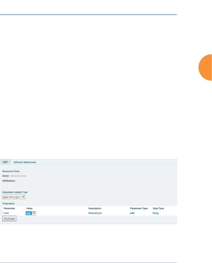
Wireless Access Point
Using Tools on the Wireless AP 429
The API Documentation page lists all of the APIs that are available, lists their
calling parameters, if any, and allows you to perform sample calls and view
sample output.
Status/Settings
The RESTful API on the AP is broken into these two main headings: status and
settings. Each is a node that may be clicked to expand or collapse the list of
corresponding API requests available on the AP. Since this is a read-only API, the
list consists exclusively of GET operations.
The figure below shows part of the list displayed by clicking /settings. Click again
to collapse (hide) the list.
Status requests include GET requests for many of the status and statistics items
described in the chapter titled, “Viewing Status on the Wireless AP” on page 95.
Settings requests include GET requests for many of the settings described in the
chapter titled, “Configuring the Wireless AP” on page 161
GET Requests
Each request name in the list is a link. Click it to see more information and to try
the API and see its output.
he
Figure 207. API — GET Request Details

Wireless Access Point
430 Using Tools on the Wireless AP
The figure above shows the GET request for ethernet-stats{name}. Click again to
collapse (hide) the API details.
High-level details are shown, including the Response Class name and the
Response Content Type (limited to JSON at this time).
Trying a GET Request
The Try it out! button allows you to send the GET request to the AP API and see
its response. Developers can use this feature to design and implement
applications that use this response.
Enter any necessary Parameters and click the Try it out! button. Most GET
requests do not use any parameters. If they are required, their names will be listed
and there will be a field or a drop-down list to specify each one. An example is
shown in Figure 207. In some cases, there may be two versions of a request, with
and without parameters. For example, GET /ethernet-stats/{name} returns status
and statistics for a particular Ethernet port, while GET /ethernet-stats/ returns
information for all Ethernet ports.
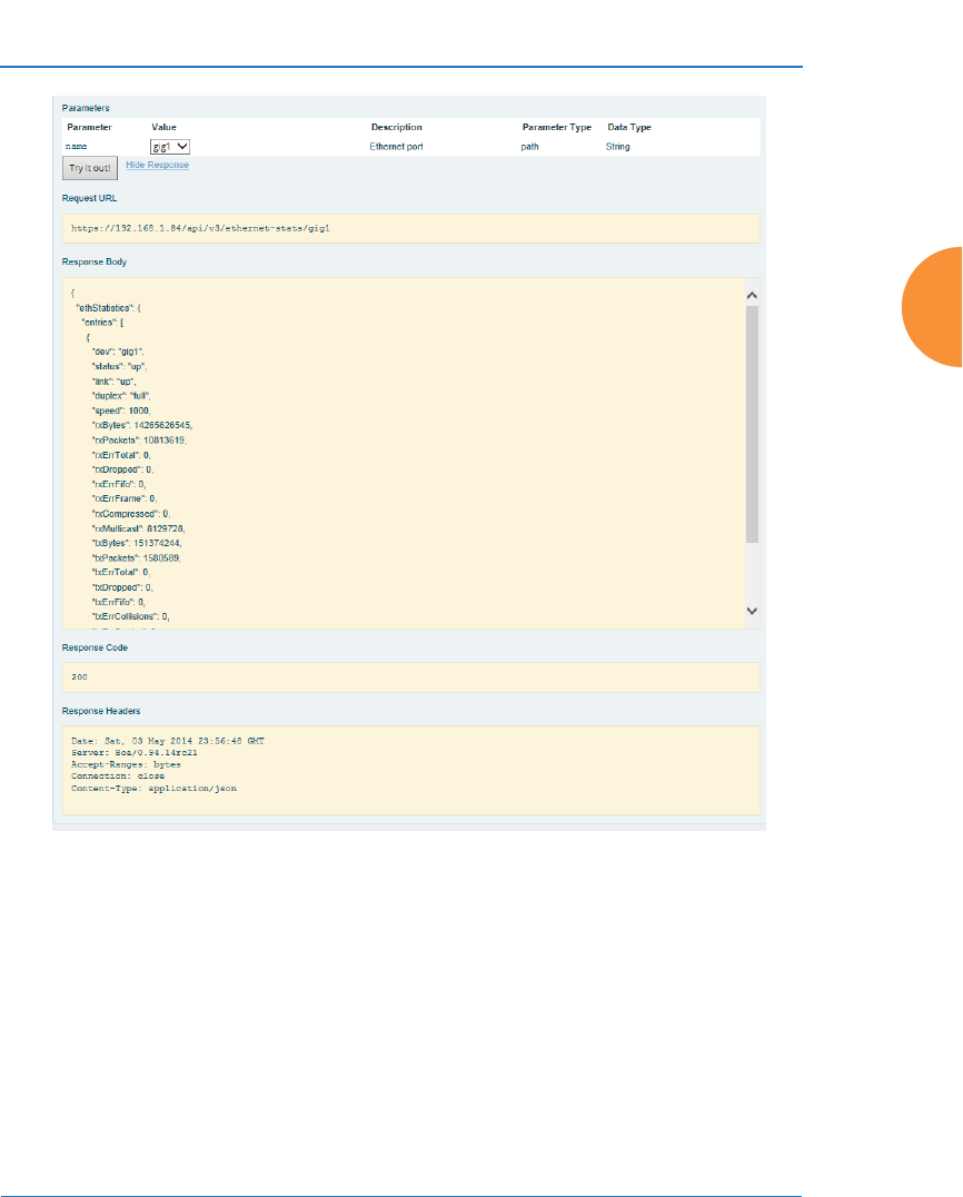
Wireless Access Point
Using Tools on the Wireless AP 431
Figure 208. API — GET Request Response
The figure above shows the response for ethernet-stats{name}. The response is
produced in the human-readable JSON format. The status and statistics data
shown are as described in “Viewing Status on the Wireless AP” on page 95. Click
Hide Response if you wish to hide the output.
The Response Code and the Response Header are standard for HTTP(S).

Wireless Access Point
432 Using Tools on the Wireless AP
API Documentation Toolbar
Figure 209. API Documentation Toolbar
The Status and Settings sections each have a toolbar as shown above, offering the
following options.
z
Show/Hide—expands or collapses this list of GET requests. Hiding and
then showing again displays the requests as they were before, i.e.,
expanded GET requests will still be expanded when displayed again.
z
List Operations—expands this list of GET requests. Each individual
entry is collapsed.
z
Expand Operations—shows all of the GET requests in this list. Each
individual entry is expanded.
z
Raw—shows the source XML code for this list of GET requests. Click the
link for the API Documentation page again to return to the normal
display.

Wireless Access Point
Using Tools on the Wireless AP 433
Options
This window allows you to customize the behavior of the WMI.
Figure 210. WMI Display Options
Procedure for Configuring Options
1. Refresh Interval in Seconds: Many of the windows in the Status section
of the WMI have an Auto Refresh option. You may use this setting to
change how often a status or statistics window is refreshed, if its auto
refresh option is enabled. Enter the desired number of seconds between
refreshes. The default refresh interval is 30 seconds.

Wireless Access Point
434 Using Tools on the Wireless AP
Logout
Click on the Logout button to terminate your session. When the session is
terminated, you are presented with the login window.
Figure 211. Login Window

Wireless Access Point
The Command Line Interface 435
The Command Line Interface
This section covers the commands and the command structure used by the AP’s
Command Line Interface (CLI), and provides a procedure for establishing an SSH
connection to the AP. Topics discussed include:
z
“Establishing a Secure Shell (SSH) Connection” on page 435.
z
“Getting Started with the CLI” on page 437.
z
“Top Level Commands” on page 440.
z
“Configuration Commands” on page 452.
z
“Sample Configuration Tasks” on page 497.
See Also
Zero-Touch Provisioning and Ongoing Management
Network Map
System Tools
Establishing a Secure Shell (SSH) Connection
Use this procedure to initialize the system and log in to the Command Line
Interface (CLI) via a Secure Shell (SSH) utility, such as PuTTY. When connecting to
the unit’s Command Line Interface over a network connection, you must use a
Secure SHell version 2 (SSH-2) utility. Make sure that your SSH utility is set up to
use SSH-2.
1. Start your SSH session and communicate with the AP via its IP address.
•If the AP is connected to a network that uses DHCP, use the address
assigned by DHCP. We recommend that you have the network
#Some commands are only available if the AP’s license includes appropriate
features or if the AP model supports it. If a command is unavailable, an error
message will notify you. See “About Licensing and Upgrades” on
page 412.
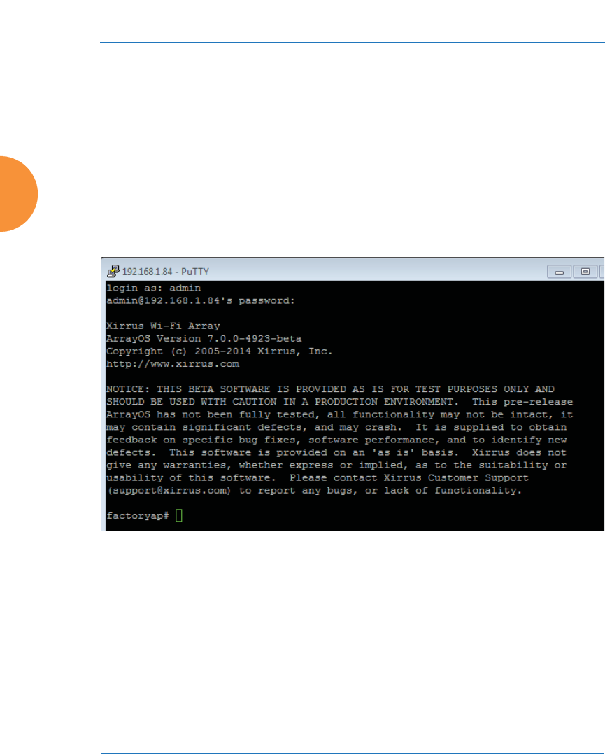
Wireless Access Point
436 The Command Line Interface
administrator assign a reserved address to the AP for ease of access in
the future.
•If the network does not use DHCP, use the factory default address
10.0.2.1 to access either the Gigabit 1 or Gigabit 2 Ethernet port. You
may need to change the IP address of the port on your computer that
is connected to the AP — change that port’s IP address so that it is on
the same 10.0.2.xx subnet as the AP port.
2. At the login prompt, enter your user name and password (the default for
both is admin). Login names and passwords are case-sensitive. You are
now logged in to the AP’s Command Line Interface.
Figure 212. Logging In

Wireless Access Point
The Command Line Interface 437
Getting Started with the CLI
The root command prompt (Root Command Prompt) is the first prompt you see
after logging in to the CLI. If you are at a level other than the root command
prompt you can return to this prompt at any time by using the exit command to
step back through each command prompt level. The root command prompt you
see in the CLI window is determined by the host name you assigned to your AP.
The prompt Xirrus_Wi-Fi_AP is displayed throughout this document simply as a
sample host name assigned to the AP. To terminate your session at any time, use
the quit command.
Entering Commands
When typing commands, you need only type enough characters to uniquely
specify the command. For example, you can type the abbreviated term config to
access the configure prompt, or even simply type c, since no other top level
command starts with “c”.
Getting Help
The CLI offers the following two levels of assistance:
z
help Command
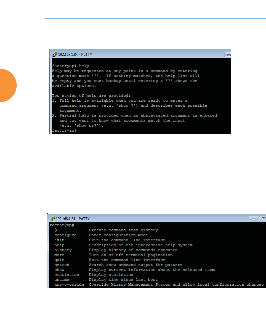
Wireless Access Point
438 The Command Line Interface
The help command is only available at the root command prompt.
Initiating this command generates a window that provides information
about the types of help that are available with the CLI.
Figure 213. Help Window
z
? Command
This command is available at any prompt and provides either FULL or
PARTIAL help. Using the ? (question mark) command when you are
ready to enter an argument will display all the possible arguments (full
help). Partial help is provided when you enter an abbreviated argument
and you want to know what arguments will match your input.
Figure 214. Full Help
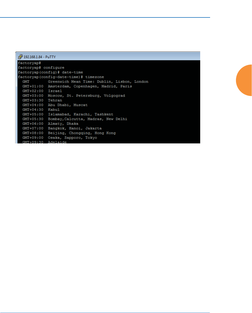
Wireless Access Point
The Command Line Interface 439
Figure 215 shows an example of how the Help system can provide the
argument and format when specifying the time zone under the date-time
command.
Figure 215. Partial Help

Wireless Access Point
440 The Command Line Interface
Top Level Commands
This section offers an at-a-glance view of all top level commands — organized
alphabetically. Top level commands are defined here as commands that are
directly accessible from the root command prompt that consists of the name of the
AP followed by a “#” sign (e.g. MyAP#). When inputting commands, be aware
that all commands are case-sensitive.
All other commands are considered second level configuration commands —
these are the commands you use to configure specific elements of the AP’s
features and functionality. For a listing of these commands with examples of
command formats and structure, go to “Configuration Commands” on page 452.
Root Command Prompt
The following table shows the top level commands that are available from the
root command prompt [MyAP].
Command Description
@ Type @n to execute command n (as shown by the
history command).
configure Enter the configuration mode. See “Configuration
Commands” on page 452.
exit Exit the CLI and terminate your session — if this
command is used at any level other than the root
command prompt you will simply exit the current
level (step back) and return to the previous level.
help Show a description of the interactive help system.
See also, “Getting Help” on page 437.
history List history of commands that have been
executed.
more Turn terminal pagination ON or OFF.
quit Exit the Command Line Interface (from any level).
search Search for pattern in show command output.

Wireless Access Point
The Command Line Interface 441
configure Commands
The following table shows the second level commands that are available with the
top level configure command [MyAP(config)#].
show Display information about the selected item. See
“show Commands” on page 445.
statistics Display statistical data about the AP. See
“statistics Commands” on page 450.
uptime Display the elapsed time since the last boot.
xms-override Override XMS managed mode and allow local
configuration changes according to your user
privileges. See “Managing APs Locally or Using
XMS” on page 85.
Command Description
@ Type @n to execute command n (as shown by the
history command).
acl Configure the Access Control List.
activation Start or stop activation server polling
admin Define administrator access parameters.
auth Configure Oauth tokens.
authentication-
server
Configure authentication server parameters
boot-env Display or modify boot loader environment
variables.
cdp Configure Cisco Discovery Protocol settings.
clear Remove/clear the requested elements.
Command Description

Wireless Access Point
442 The Command Line Interface
cluster Make configuration changes to multiple APs.
contact-info Contact information for assistance on this AP.
date-time Configure date and time settings.
dhcp-server Configure the DHCP Server.
dns Configure the DNS settings.
end Exit the configuration mode.
exit Go UP one mode level.
file Manage the file system.
filter Define protocol filter parameters.
group Define user groups with parameter settings
help Description of the interactive Help system.
history List history of commands that have been
executed.
hostname Host name for this AP.
interface Select the interface to configure.
lldp Configure LLDP settings
load Load running configuration from flash
location Location name for this AP.
location-
reporting
Configure location server settings.
management Configure AP management parameters
mdm Configure mobile device management server
settings.
more Turn ON or OFF terminal pagination.
Command Description

Wireless Access Point
The Command Line Interface 443
netflow Configure NetFlow data collector.
no Disable (if enabled) or set to default value.
proxy-fwd Configure Proxy Forwarding settings.
quick-config Apply configuration template for typical
deployment scenario.
quit Exit the Command Line Interface.
reboot Reboot the AP.
reset Reset all settings to their factory default values
and reboot.
restore Reset all settings to their factory default values
and reboot.
revert Revert to saved configuration after specified delay
in seconds if configuration not saved.
roaming-assist Set parameters for roaming assistance.
run-tests Run selective tests.
save Save the running configuration to FLASH.
search Search for pattern in show command output.
security Set the security parameters for the AP.
show Display current information about the selected
item.
snmp Enable, disable or configure SNMP.
ssid Configure the SSID parameters.
station-
assurance
Location name for this AP.
statistics Display statistics.
Command Description

Wireless Access Point
444 The Command Line Interface
syslog Enable, disable or configure the Syslog Server.
tunnel Configure tunnels.
uptime Display time since the last boot.
vlan Configure VLAN parameters.
wifi-tag Configure VLAN parameters.
xms-override Override XMS managed mode and allow local
configuration changes according to your user
privileges. See “Managing APs Locally or Using
XMS” on page 85.
Command Description

Wireless Access Point
The Command Line Interface 445
show Commands
The following table shows the second level commands that are available with the
top level show command [MyAP# show].
Command Description
acl Display the Access Control List.
active-directory Show Active Directory information.
admin Display the administrator list or login
information.
applications Application statistics.
arp ARP table information.
associated-
stations
Display stations that have associated to the AP.
auth Show Open Authentication tokens.
authentication-
server
Authentication server settings summary.
bond Bond information
boot-env Display Boot loader environment variables.
capabilities Display detailed station capabilities.
cdp Display Cisco Discovery Protocol settings.
channel-list Display list of AP’s 802.11an and bgn channels.
cluster Display Cluster summary.
clear-text Display and enter passwords and secrets in the
clear.
conntrack Display the Connection Tracking table.
console Display terminal settings.
contact-info Display contact information.

Wireless Access Point
446 The Command Line Interface
country-list Display countries that the AP can be set to
support.
date-time Display date and time settings summary.
dhcp-leases Display IP addresses (leases) assigned to stations
by the DHCP server.
dhcp-pool Display internal DHCP server settings summary
information.
diff Display the difference between configurations.
dns Display DNS summary information.
env-ctrl Display the environmental controller status for the
outdoor enclosure.
error-numbers Display the detailed error number in error
messages.
ethernet Display Ethernet interface summary information.
external-radius Display summary information for the external
RADIUS server settings.
factory-config Display the AP factory configuration information.
filter Display filter information.
filter-list Filter list information.
group User Group summary.
iap Display IAP configuration information.
ids-event-log IDS event log.
ids-stats IDS statistics
internal-radius Display the users defined for the embedded
RADIUS server.
intrude-detect Intrusion detection information.
Command Description

Wireless Access Point
The Command Line Interface 447
lastboot-config Display AP configuration at the time of the last
boot-up.
lldp Link Layer Discovery Protocol information.
location-
reporting
Location server reporting information.
mac-table MAC address bridging table
management Display settings for managing the AP, plus
Standby, FIPS, and other information.
mdm MDM (Mobile Device Management) information
netflow NetFlow information
network-
assurance
Network Assurance status
network-map Display network map information.
proxy-fwd Display Proxy Forwarding summary.
radio-assurance Radio Assurance status.
realtime-monitor Display realtime statistics for all IAPs.
roaming-assist Roaming assist settings
roaming-stations Roaming station information
rogue-ap Display rogue AP information.
route Display the routing table.
rssi-map Display RSSI map by IAP for station.
running-config Display configuration information for the AP
currently running.
saved-config Display the last saved AP configuration.
security Display security settings summary information.
Command Description

Wireless Access Point
448 The Command Line Interface
self-test Display self test results.
snmp Display SNMP summary information.
spanning-tree Display spanning tree information.
spectrum-
analyzer
Display spectrum analyzer measurements.
ssid Display SSID summary information.
station-
assurance
Station assurance information.
stations Display station information.
statistics Display statistics.
syslog Display the system log.
syslog-settings Display the system log (Syslog) settings.
system-info System information
temperature Display the current board temperatures.
tunnel Tunnel information
unassociated-
stations
Display unassociated station information.
undefined-vlan Undefined VLANs detected
uptime Display time since last boot.
vlan Display VLAN information.
wds Display WDS information.
wifi-tag Display WiFi tag summary.
wpr-whitelist Show WPR whitelist
xrp-tunnels XRP tunnel information.
Command Description

Wireless Access Point
The Command Line Interface 449
<cr> Display configuration or status information.
IAP-NAME
iap1, iap2
IAP interface information
Command Description

Wireless Access Point
450 The Command Line Interface
statistics Commands
The following table shows the second level commands that are available with the
top level statistics command [MyAP# statistics].
Command Description
ethernet Display statistical data for all Ethernet interfaces.
filter Display statistics for defined filters (if any).
FORMAT:
statistics filter [detail]
filter-list Display statistics for defined filter list (if any).
FORMAT:
statistics filter <filter-list>
iap Display statistical data for the defined IAP.
FORMAT:
statistics iap iap2
station Display statistical data about associated stations.
FORMAT:
statistics station billw
vlan Display statistical data for the defined VLAN. You
must use the VLAN number (not its name) when
defining a VLAN.
FORMAT:
statistics vlan 1
wds Display statistical data for the defined active WDS
(Wireless Distribution System) links.
FORMAT:
statistics wds 1
<cr> Display configuration or status information.

Wireless Access Point
The Command Line Interface 451
Ethernet Name
eth0, gig1, gig2
Display statistical data for the defined Ethernet
interface (either eth0, gig1 or gig2).
FORMAT:
statistics gig1
IAP-NAME
iap1, iap2
IAP interface information
Command Description

Wireless Access Point
452 The Command Line Interface
Configuration Commands
All configuration commands are accessed by using the configure command at the
root command prompt (MyAP#). This section provides a brief description of each
command and presents sample formats where deemed necessary. The commands
are organized alphabetically. When inputting commands, be aware that all
commands are case-sensitive.
To see examples of some of the key configuration tasks and their associated
commands, go to “Sample Configuration Tasks” on page 497.
acl
The acl command [MyAP(config)# acl] is used to configure the Access Control
List.
Command Description
add Add a MAC address to the list.
FORMAT:
acl add AA:BB:CC:DD:EE:FF
del Delete a MAC address from the list.
FORMAT:
acl del AA:BB:CC:DD:EE:FF
disable Disable the Access Control List
FORMAT:
acl disable
enable Enable the Access Control List
FORMAT:
acl enable
reset Delete all MAC addresses from the list.
FORMAT:
acl reset

Wireless Access Point
The Command Line Interface 453
admin
The admin command [MyAP(config-admin)#] is used to configure the
Administrator List.
Command Description
add Add a user to the Administrator List.
FORMAT:
admin add [userID]
del Delete a user to the Administrator List.
FORMAT:
admin del [userID]
edit Modify user in the Administrator List.
FORMAT:
admin edit [userID]
privilege-name Define administrator privilege level names
privilege-section Define administrator privilege level required by
config section.
radius Define a RADIUS server to be used for
authenticating administrators.
FORMAT:
admin radius [disable | enable | off | on |
timeout <seconds> | auth-type [PAP | CHAP]]
admin radius [primary |secondary]
port <portid> server [<ip-addr> | <host>]
secret <shared-secret>
reset Delete all users and restore the default user.
FORMAT:
admin reset

Wireless Access Point
454 The Command Line Interface
auth
The auth command [MyAP(config)# auth] is used to configure Oauth tokens.
See also, “OAuth 2.0 Management” on page 265.
cdp
The cdp command [MyAP(config)# cdp] is used to configure the Cisco Discovery
Protocol.
Command Description
del Delete an Oauth token.
FORMAT:
auth del <Oauth token>
reset Delete all Oauth tokens.
FORMAT:
auth reset
Command Description
disable Disable the Cisco Discovery Protocol
FORMAT:
cdp disable
enable Enable the Cisco Discovery Protocol
FORMAT:
cdp enable
hold-time Select CDP message hold time before messages
received from neighbors expire.
FORMAT:
cdp hold-time [# seconds]

Wireless Access Point
The Command Line Interface 455
interval The AP sends out CDP announcements at this
interval.
FORMAT:
cdp interval [# seconds]
off Disable the Cisco Discovery Protocol
FORMAT:
cdp off
on Enable the Cisco Discovery Protocol
FORMAT:
cdp on
Command Description

Wireless Access Point
456 The Command Line Interface
clear
The clear command [MyAP(config)# clear] is used to clear requested elements.
Command Description
arp Clear the arp table entry for a requested IP
address, or clear all entries if no IP address is
entered.
FORMAT:
clear arp [ipaddress]
authentication Deauthenticate a station (specified by MAC
address, hostname, or IP address). If you specify
the permanent option, then the station is
deauthenticated and put on the access control list.
FORMAT:
clear authentication [permanent] [authenticated
station]
history Clear the history of CLI commands executed.
FORMAT:
clear history
screen Clear the screen where you’re viewing CLI
output.
FORMAT:
clear screen
station-
assurance
Clear all station assurance data, but continue to
collect new data.
FORMAT:
clear station-assurance
statistics Clear the statistics for thee change, but it won’t
show up requested element.
FORMAT:
clear statistics [ethname | all-eth | applications
| filters |iap | station | vlan | wds]

Wireless Access Point
The Command Line Interface 457
syslog Clear all Syslog messages, but continue to log new
messages.
FORMAT:
clear syslog
undefined-vlan Clear undefined VLAN information.
FORMAT:
clear undefined-vlan
Command Description

Wireless Access Point
458 The Command Line Interface
cluster
The cluster command [MYAP(config)# cluster] is used to create and operate
clusters. Clusters allow you to configure multiple APs at the same time. Using
CLI (or WMI), you may define a set of APs that are members of the cluster. Then
you may switch the AP to Cluster operating mode for a selected cluster, which
sends all successive configuration commands issued via CLI or WMI to all of the
member APs. When you exit cluster mode, configuration commands revert to
applying only to the AP to which you are connected.
For more information, see “Clusters” on page 401.
Command Description
add Create a new AP cluster. Enters edit mode for that
cluster to allow you to specify the APs that belong
to the cluster.
FORMAT:
cluster add [cluster-name]
del Delete an AP cluster. Type del? to list the existing
clusters.
FORMAT:
cluster del [cluster-name]
edit Enter edit mode for selected cluster to add or
delete APs that belong to the cluster.
FORMAT:
cluster edit [cluster-name]
operate Enter Cluster operation mode. All configuration
commands are applied to all of the selected
cluster’s member APs until you give the end
command (see above).
FORMAT:
cluster operate [cluster-name]
reset Delete all clusters.
FORMAT:
cluster reset

Wireless Access Point
The Command Line Interface 459
contact-info
The contact-info command [MyAP(config)# contact-info] is used for managing
administrator contact information.
Command Description
email Add an email address for the contact (must be in
quotation marks).
FORMAT:
contact-info email [“contact@mail.com”]
name Add a contact name (must be in quotation marks).
FORMAT:
contact-info name [“Contact Name”]
phone Add a telephone number for the contact (must be
in quotation marks).
FORMAT:
contact-info phone [“8185550101”]

Wireless Access Point
460 The Command Line Interface
date-time
The date-time command [MyAP(config-date-time)#] is used to configure the
date and time parameters. Your AP supports the Network Time Protocol (NTP) in
order to ensure that the AP’s internal time is accurate. NTP is set to UTC time by
default; however, you can set the time zone so that your AP will display local
time. This is done by defining an offset from the UTC value. For example, Pacific
Standard Time is 8 hours behind UTC time, so the offset from UTC time would be
-8.
Command Description
dst_adjust Enable adjustment for daylight savings.
FORMAT:
date-time dst_adjust
no Disable daylight savings adjustment.
FORMAT:
date-time no dst_adjust
ntp Enable the NTP server.
FORMAT:
date-time ntp on (or off to disable)
offset Set an offset from Greenwich Mean Time.
FORMAT:
date-time no dst_adjust
set Set the date and time for the AP.
FORMAT:
date-time set [10:24 10/23/2007]
timezone Configure the time zone.
FORMAT:
date-time timezone [-8]

Wireless Access Point
The Command Line Interface 461
dhcp-server
The dhcp-server command [MyAP(config-dhcp-server)#] is used to add, delete
and modify DHCP pools.
Command Description
add Add a DHCP pool.
FORMAT:
dhcp-server add [dhcp pool]
del Delete a DHCP pool.
FORMAT:
dhcp-server del [dhcp pool]
edit Edit a DHCP pool
FORMAT:
dhcp-server edit [dhcp pool]
reset Delete all DHCP pools.
FORMAT:
dhcp-server reset

Wireless Access Point
462 The Command Line Interface
dns
The dns command [MyAP(config-dns)#] is used to configure your DNS
parameters.
Command Description
domain Enter your domain name.
FORMAT:
dns domain [www.mydomain.com]
server1 Enter the IP address of the primary DNS server.
FORMAT:
dns server1 [1.2.3.4]
server2 Enter the IP address of the secondary DNS server.
FORMAT:
dns server1 [2.3.4.5]
server3 Enter the IP address of the tertiary DNS server.
FORMAT:
dns server1 [3.4.5.6]
use-dhcp Enable or disable updates to DNS settings via
DHCP.
FORMAT:
dns use-dhcp [off | on]

Wireless Access Point
The Command Line Interface 463
file
The file command [MyAP(config-file)#] is used to manage files.
Command Description
active-image Validate and commit a new AP software image.
backup-image Validate and commit a new backup software image.
cat List file contents.
check-image Validate a new AP software image.
chkdsk Check flash file system.
copy
cp
Copy a file to another file.
FORMAT:
file copy [sourcefile destinationfile]
create-text Create a text file on the flash file system, <EOF> to
finish.
dir List the contents of a directory.
FORMAT:
file dir [directory]
erase Delete a file from the FLASH file system.
FORMAT:
file erase [filename]
format Format flash file system.
ftp Open an FTP connection with a remote server. Files
will be transferred in binary mode.
FORMAT:
file ftp host {<hostname> |<ip>} [port <port_#>]
[user {anonymous | <username> password
<passwd> } ] { put <source_file> [<dest_file>] |
get <source_file> [<dest_file>] }
Note: Any time you transfer any kind of software
image file for the AP, it must be transferred in binary
mode, or the file may be corrupted.

Wireless Access Point
464 The Command Line Interface
http-get Perform an HTTP file download. This is the
preferred method of downloading files for XMS
Cloud.
FORMAT:
http-get [no-cert-check] <url> [<local_file>]
no-cert-check causes the AP to download the file
even if the SSL certificate is invalid, expired, or not
signed by a recognized CA
<url> is a standard HTTP URL, e.g. https://
file.example.com:8080/mydir/myfile.ext.
z
http:// or https:// may be omitted, in which
case HTTP is assumed
<local_file> is an optional parameter that describes
the path and name where the file should be saved
z
if no local_file is specified, the file will be
saved in the root of the flash storage
z
the local_file does support specifying a
directory, which will be created if it doesn't
already exist
list List the contents of a file.
FORMAT:
file list [filename]
mkdir Create a directory on the flash file system.
mv Rename a file on the flash file system.
Command Description

Wireless Access Point
The Command Line Interface 465
remote-config When the AP boots up, it fetches the specified
configuration file from the TFTP server defined in
the file remote-server command, and uses this
configuration. This must be an AP configuration file
with a .conf extension.
A partial configuration file may be used. For
instance, if you wish to use a single configuration file
for all of your APs but don't want to have the same
IP address for each AP, you may remove the ipaddr
line from the file. You can then load the file on each
AP and the local IP addresses will not change.
FORMAT:
file remote-config <config-file.conf>
Note: If you enter file remote-config ?, the help
response suggests possibilities by listing all of the
configuration files that are currently in the AP’s
flash.
remote-image When the AP boots up, it fetches the named image
file from the TFTP server defined in the file remote-
server command, and upgrades to this file before
booting. This must be an AP image file with a .bin
extension.
FORMAT:
file remote-image <image-file.bin>
Note: This will happen every time that the AP
reboots. If you only want to fetch the remote-image
one time be sure to turn off the remote image option
after the initial download.
remote-server Sets up a TFTP server to be used for automated
remote update of software image and configuration
files when rebooting.
FORMAT:
file remote-server A.B.C.D
rename Rename a file.
rm Delete a file from the flash file system.
Command Description

Wireless Access Point
466 The Command Line Interface
rmdir Delete a directory on the flash file system.
scp Copy a file to or from a remote system. You may
specify the port to use.
tftp Open a TFTP connection with a remote server.
FORMAT:
file tftp host {<hostname> |<ip>} [port <port_#>]
[user {anonymous | <username> password
<passwd> } ] { put <source_file> [<dest_file>] |
get <source_file> [<dest_file>] }
Note: Any time you transfer any kind of software
image file for the AP, it must be transferred in binary
mode, or the file may be corrupted.
Command Description

Wireless Access Point
The Command Line Interface 467
filter
The filter command [MyAP(config-filter)#] is used to manage protocol filters
and filter lists.
Command Description
add Add a filter. Details about the air cleaner feature
are after the end of this table.
FORMAT:
filter add [air-cleaner |name]
add-list Add a filter list.
FORMAT:
filter add-list [name]
del Delete a filter.
FORMAT:
filter del [name]
del-list Delete a filter list.
FORMAT:
filter del-list [name]
edit Edit a filter.
FORMAT:
filter edit [name type]
edit-list Edit a filter list
FORMAT:
filter edit-list [name type]
enable Enable a filter list.
FORMAT:
filter enable
move Change a filter priority.
FORMAT:
filter move [name priority]

Wireless Access Point
468 The Command Line Interface
Air Cleaner
The air cleaner feature offers a number of predetermined filter rules that eliminate
a great deal of unnecessary wireless traffic, resulting in improved performance.
You may select all of the air cleaner rules for the greatest effect, or only specific
rules, such as broadcast or multicast, to eliminate only a particular source of
traffic. The following options are offered:
MyAP(config)# filter add air-cleaner
all All air cleaner filters
arp Eliminate station to station ARPs over the air
broadcast Eliminate broadcast traffic from the air
dhcp Eliminate stations serving DHCP addresses from the air
multicast Eliminate chatty multicast traffic from the air
netbios Eliminate NetBIOS traffic from the air
off Disable a filter list.
FORMAT:
filter off
on Enable a filter list.
FORMAT:
filter on
reset Delete all protocol filters and filter lists.
FORMAT:
filter reset
stateful Enable or disable stateful filtering (firewall).
FORMAT:
Stateful [enable | disable | on |off]
track-apps Enable or disable application tracking.
FORMAT:
filter track-apps [enable | disable | on |off]
Command Description
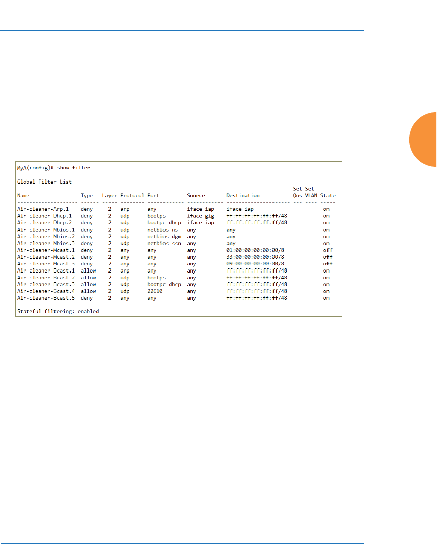
Wireless Access Point
The Command Line Interface 469
If you select all, the rules shown in Figure 216 are added to the predefined filter
list named Global. These rules assume that you have station-to-station blocking
enabled, that a DHCP server is on the AP’s wired connection, and that you want
to block most all multicast and all broadcast traffic not vital to normal operation.
If you find that there is a particular type of multicast or broadcast traffic that you
want to allow, just add a specific allow filter for it before the deny filter in this list
that would normally block it. Add or delete any of the Multicast rules as
necessary for a specific site. Remember that the order of the rules is important.
Figure 216. Air Cleaner Filter Rules
Explanations of some sample rules are below.
z
Air-cleaner-Arp.1 blocks ARPs from one client from being transmitted to
clients via all of the radios. The station to station block setting doesn't
block this traffic, so this filter eliminates this unnecessary traffic.
z
Air-cleaner-Dhcp.1 drops all DHCP client traffic coming in from the
Gigabit interface. This traffic doesn't need to be transmitted by the radios
since there shouldn't be any DHCP server associated to the radios and
offering DHCP addresses. For large subnets the DHCP discover/request
broadcast traffic can be significant.
z
Air-cleaner-Dhcp.2 drops all DHCP server traffic coming in from the
radio interfaces. There should not be any DHCP server associated to the

Wireless Access Point
470 The Command Line Interface
radios. These rogue DHCP servers are blocked from doing any damage
with this filter. There have been quite a few cases in public venues like
schools and conventions where such traffic is seen.
z
Air-cleaner-Mcast.1 drops all multicast traffic with a destination MAC
address starting with 01. This filters out a lot of IP multicast traffic that
starts with 224.
z
Air-cleaner-Mcast.2 drops all multicast traffic with a destination MAC
address starting with 33. A lot of IPv6 traffic and other multicast traffic is
blocked by this filter.
z
Air-cleaner-Mcast.3 drops all multicast traffic with a destination MAC
address starting with 09. A lot of Appletalk traffic and other multicast
traffic is blocked by this filter. Note that for OSX 10.6.* Snow Leopard no
longer supports Appletalk.
z
Air-cleaner-Bcast.1 allows all ARP traffic (other than the traffic that was
denied by Air-cleaner-Arp.1). This is needed because Air-cleaner-Bcast.5
would drop this valid traffic.
z
Air-cleaner-Bcast.4 allows all XRP traffic from APs to be received from
the wire. This is needed because Air-cleaner-Bcast.5 would drop this
valid traffic.
z
Air-cleaner-Bcast.5 drops all other broadcast traffic that hasn't previously
been explicitly allowed. This filter will catch all UDP broadcast traffic as
well as all other known and unknown protocol broadcast traffic.

Wireless Access Point
The Command Line Interface 471
group
The group command [MyAP(config)# group] is used to create and configure user
groups. User groups allow administrators to assign specific network parameters
to users through RADIUS privileges rather than having to map users to a specific
SSID. Groups provide flexible control over user privileges without the need to
create large numbers of SSIDs. For more information, see “Groups” on page 304.
hostname
The hostname command [MyAP(config)# hostname] is used to change the
hostname used by the AP.
Command Description
add Create a new user group.
FORMAT:
group add [group-name]
del Delete a user group.
FORMAT:
group del [group-name]
edit Set parameters values for a group.
FORMAT:
group edit [group-name]
reset Reset the group.
FORMAT:
group reset
Command Description
hostname Change the hostname of the AP.
FORMAT:
hostname [name]

Wireless Access Point
472 The Command Line Interface
interface
The interface command [MyAP(config)# interface] is used to select the interface
that you want to configure. To see a listing of the commands that are available for
each interface, use the ? command at the selected interface prompt. For example,
using the ? command at the MyAP(config-gig1}# prompt displays a listing of all
commands for the gig1 interface.
Command Description
bond1 Bond 1.
bond2 Bond 2.
console Select the console interface. The console interface
is used for management purposes only.
FORMAT:
interface console
gig1 Select the Gigabit 1 interface.
FORMAT:
interface gig1
gig2 Select the Gigabit 2 interface.
FORMAT:
interface gig2
iap Select an IAP.
FORMAT:
interface iap
IAP-NAME
iap1, iap2
IAP interface information

Wireless Access Point
The Command Line Interface 473
load
The load command [MyAP(config)# load] loads a configuration file.
location
The location command [MyAP(config)# location] is used to set the location
descriptive string for the AP.
Command Description
factory.conf Load the factory settings configuration file.
FORMAT:
load [factory.conf]
lastboot.conf Load the configuration file from the last boot-up.
FORMAT:
load [lastboot.conf]
[myfile].conf If you have saved a configuration, enter its name
to load it.
FORMAT:
load [myfile.conf]
saved.conf Load the configuration file with the last saved
settings.
FORMAT:
load [saved.conf]
Command Description
<cr> Set the location for the AP.
FORMAT:
location [newlocation]

Wireless Access Point
474 The Command Line Interface
location-reporting
The location-reporting command [MyAP(config)# location-reporting] is used to
configure Location Server settings. See also, “Location” on page 191.
Command Description
cust-key Set Location Server customer key.
FORMAT:
location-reporting cust-key enc <loc-server-
customer-key>
disable
off
Disable location-reporting.
FORMAT:
location-reporting disable
enable
on
Enable location-reporting.
FORMAT:
location-reporting enable
period Set Location Server reporting period (seconds).
FORMAT:
location-reporting period <#-seconds>
url Set URL of Location Server.
FORMAT:
location-reporting url <loc-server-URL>

Wireless Access Point
The Command Line Interface 475
management
The management command [MyAP(config)# management] enters management
mode, where you may configure management parameters.
The following types of settings may be configured in management mode:
Command Description
<cr> Enter management mode.
FORMAT:
management <cr>
Setting Description
activation Start or stop activation server polling.
banner Configure login banner messages.
clear Remove/clear requested elements.
cloud Enable/disable Cloud access.
console Configure console management parameters.
fips Enable/disable FIPS 140-2, Level 2 Security. See
“Implementing FIPS Security” on page 591.
help Description of the interactive help system.
history Display history of commands executed.
https Enable/disable HTTPS access.
license Set access point software license key
load Load running configuration from flash.
max-auth-
attempts
Maximum number of authentication (login)
attempts (0 means unlimited).
more Turn on or off terminal pagination.

Wireless Access Point
476 The Command Line Interface
network-
assurance
Enable/disable network assurance.
pci-audit Enable/disable PCI (Payment Card Industry)
audit mode. See “Auditing PCI DSS” on page 585.
quick-config Apply quick configuration template.
quit Exit the command line interface.
reauth-period Time between failed CLI login attempts.
restore Restore to previous saved config.
revert Revert to saved configuration after delay if
configuration not saved.
save Save running configuration to flash.
search Search show command output for pattern.
show Display current information about the selected
item.
spanning-tree Enable/disable Spanning Tree Protocol.
ssh Enable/disable SSH access.
standby Configure standby parameters.
statistics Display statistics.
telnet Enable/disable telnet access.
top Return to top level of configuration mode.
uptime Display time since last boot.
xms-override Override XMS managed mode and allow local
configuration changes according to your user
privileges. See “Managing APs Locally or Using
XMS” on page 85.
Setting Description

Wireless Access Point
The Command Line Interface 477
mdm
The mdm command [MyAP(config)# mdm] is used to configure Mobile Device
Management Server settings. See also, “Mobile” on page 406.
xircon Enable/disable Xircon access. See Xircon User’s
Guide for more information.
Command Description
airwatch api Set Location Server customer key.
FORMAT:
mdm airwatch api
The following types of settings may be configured in
management mode:
z
access-error Set AirWatch API access error action
z
key Set AirWatch API key
z
password Set AirWatch API password
z
poll-period Set AirWatch API poll period
z
timeout Set AirWatch API timeout
z
url Set AirWatch API URL
z
username Set AirWatch API username
redirect-url Set URL to redirect clients to.
FORMAT:
mdm airwatch redirect-url <URL-string>
Setting Description

Wireless Access Point
478 The Command Line Interface
more
The more command [MyAP(config)# more] is used to turn terminal pagination
ON or OFF.
Command Description
disable
off
Turn OFF terminal pagination.
FORMAT:
more off
enable
on
Turn ON terminal pagination.
FORMAT:
more on

Wireless Access Point
The Command Line Interface 479
netflow
The netflow command [MyAP(config-netflow)#] is used to enable or disable, or
configure sending IP flow information (traffic statistics) to the collector you
specify.
Command Description
collector Set the Netflow collector IP address or fully
qualified domain name (host.domain). Only one
collector may be set. If port is not specified, the
default is 2055.
FORMAT:
netflow collector host {<ip-addr> | <domain>}
[port <port#>]
disable
off
Disable netflow.
FORMAT:
netflow disable
ipfix Enable NetFlow IPFIX probe.
off Disable netflow.
FORMAT:
netflow off
v5 Enable NetFlow v5 probe.
v9 Enable Netflow v9 probe.

Wireless Access Point
480 The Command Line Interface
no
The no command [MyAP(config)# no] is used to disable a selected element or set
the element to its default value.
Command Description
2.4GHz Disable all 2.4GHz IAPs.
5GHz Disable all 5GHz IAPs.
acl Disable the Access Control List.
FORMAT:
no acl
clear-text Disable entry and display of passwords and
secrets in the clear.
gig1 Disable gig1.
gig2 Disable gig2.
https Disable https access.
FORMAT:
no https
intrude-detect Disable intrusion detection.
FORMAT:
no intrude-detect
management Disable management on all Ethernet interfaces.
FORMAT:
no management
more Disable terminal pagination.
FORMAT:
no more
ntp Disable the NTP server.
FORMAT:
no ntp

Wireless Access Point
The Command Line Interface 481
quick-config
The quick-config command is used to apply configuration templates to the AP
for typical deployment scenarios.
snmp Disable SNMP features.
FORMAT:
no snmp
spanning-tree Disable spanning tree.
ssh Disable ssh access.
FORMAT:
no ssh
syslog Disable the Syslog services.
FORMAT:
no syslog
telnet Disable Telnet access.
FORMAT:
no telnet
Command Description
Classroom Configure AP for classroom deployment.
FORMAT:
quick-config Classroom
Configures the AP for use in classroom settings
(K-12 schools, Higher education, etc.)
High-density Configure AP for high density deployment.
FORMAT:
quick-config High-density
Configures the AP for use in high density settings
(lecture halls, convention centers, stadiums, etc.)
Command Description

Wireless Access Point
482 The Command Line Interface
quit
The quit command [MyAP(config)# quit] is used to exit the Command Line
Interface.
authentication-server
The authentication-server command [MyAP(config-authserver)#] is used to
configure the external and internal RADIUS server parameters.
Command Description
<cr> Exit the Command Line Interface.
FORMAT:
quit
If you have made any configuration changes and
your changes have not been saved, you are
prompted to save your changes to Flash.
At the prompt, answer Yes to save your changes,
or answer No to discard your changes.
Command Description
active-directory Configure Active Directory parameters.
external-radius Configure an external RADIUS server.
FORMAT:
authentication-server external-radius
To configure a RADIUS server (primary,
secondary, or accounting server, by IP address or
host name), and the reporting interval use:
authentication-server external-radius accounting
internal-radius Configure the internal RADIUS server.
FORMAT:
authentication-server internal-radius

Wireless Access Point
The Command Line Interface 483
use Choose the active RADIUS server (either external
or internal).
FORMAT:
authentication-server use external (or internal)
Command Description

Wireless Access Point
484 The Command Line Interface
reboot
The reboot command [MyAP(config)# reboot] is used to reboot the AP. If you
have unsaved changes, the command will notify you and give you a chance to
cancel the reboot.
reset
The reset command [MyAP(config)# reset] is used to reset all settings to their
default values then reboot the AP.
Command Description
<cr> Reboot the AP.
FORMAT:
reboot
delay Reboot the AP after a delay of 1 to 60 seconds.
FORMAT:
reboot delay [n]
Command Description
<cr> Reset all configuration parameters to their factory
default values.
FORMAT:
reset
The AP is rebooted automatically.
preserve-ip-
settings
Preserve all ethernet and VLAN settings and reset
all other configuration parameters to their factory
default values.
FORMAT:
reset preserve-ip-settings
The AP is rebooted automatically.

Wireless Access Point
The Command Line Interface 485
restore
The restore command [MyAP(config)# restore] is used to restore configuration to
a version that was previously saved locally.
Command Description
?Use this to display the list of available config files.
FORMAT:
restore ?
<filename> Enter the name of the locally saved configuration
to restore.
FORMAT:
restore <config-filename>

Wireless Access Point
486 The Command Line Interface
roaming-assist
The roaming-assist command [MyAP(config)# roaming-assist] is used to
configure roaming assistance settings. See also, “Roaming Assist” on page 382.
Command Description
data-rate Set minimum packet data rate before roaming, in
Mbps.
FORMAT:
roaming-assist data-rate <1-99>
devices Set device types or classes to assist.
FORMAT:
roaming-assist devices all | unidentified |
DEVICE-CLASS <ID-string> | DEVICE-TYPE
<ID-string>
disable
off
Disable roaming assist.
FORMAT:
roaming-assist disable
enable
on
Enable roaming assist.
FORMAT:
roaming-assist enable
period Set roaming assist backoff period (seconds).
FORMAT:
roaming-assist period <#-seconds>
threshold Set roaming RSSI threshold in db relative to RSSI
of nearest AP.
FORMAT:
roaming-assist threshold <-50 to 50>

Wireless Access Point
The Command Line Interface 487
run-tests
The run-tests command [MyAP(run-tests)#] is used to enter run-tests mode,
which allows you to perform a range of tests on the AP.
Command Description
@Execute command from history
ad-authenticate Test domain user authentication.
ad-check-secret Check machine trust secret.
ad-debug-info Display detailed Active Directory information.
ad-list-groups List all domain groups.
ad-status Display Active Directory status.
capture Execute a packet capture.
clear Remove/clear requested elements.
diagnostic-log Generate diagnostic log file.
end Exit configuration mode.
help Description of the interactive help system.
history Display history of commands executed.
iperf Execute iperf utility.
FORMAT:
run-tests iperf
led LED test.
FORMAT:
run-tests led [flash | rotate]
memtest Execute memory tests.
FORMAT:
run-tests memtest
more Turn on or off terminal pagination.

Wireless Access Point
488 The Command Line Interface
ping Execute ping utility.
FORMAT:
run-tests ping [host-name | ip-addr]
quick-config Apply quick configuration template.
quit Exit the command line interface.
radius-ping Special ping utility to test the connection to a
RADIUS server.
FORMAT:
run-tests radius-ping [external | ssid <ssidnum>]
[primary | secondary] user <raduser> password
<radpasswd> auth-type [CHAP | PAP]
run-tests radius-ping [internal | server
<radserver> port <radport> secret <radsecret> ]
user <raduser> password <radpasswd>
auth-type [CHAP | PAP]
You may select a RADIUS server that you have
already configured (ssid or external or internal) or
specify another server.
restore Restore to previous saved configuration.
revert Revert to saved configuration after delay if
configuration is not saved.
save Save running configuration to flash.
search Search show command output for pattern.
show Display current information about the selected item.
site-survey Enable or disable site survey mode.
FORMAT:
run-tests site-survey [on | off | enable | disable]
Command Description

Wireless Access Point
The Command Line Interface 489
security
The security command [MyAP(config-security)#] is used to establish the security
parameters for the AP.
ssh Execute ssh utility.
FORMAT:
run-tests ssh [hostname | ip-addr]
[command-line-switches (optional)]
tcpdump Execute tcpdump utility to dump traffic for selected
interface or VLAN. Supports 802.11 headers.
FORMAT:
run-tests tcpdump
telnet Execute telnet utility.
FORMAT:
run-tests telnet [hostname | ip-addr]
[command-line-switches (optional)]
traceroute Execute traceroute utility.
FORMAT:
run-tests traceroute [host-name | ip-addr]
uptime Display time since last boot.
Command Description
wep Set the WEP encryption parameters.
FORMAT:
security wep
wpa Set the WEP encryption parameters.
FORMAT:
security wpa
Command Description

Wireless Access Point
490 The Command Line Interface
snmp
The snmp command [MyAP(config-snmp)#] is used to enable, disable, or
configure SNMP.
Command Description
trap Configure traps for SNMP. Up to four trap
destinations may be configured, and you may
specify whether to send traps for authentication
failure.
FORMAT:
snmp trap
v2 Enable SNMP v2.
FORMAT:
snmp v2
v3 Enable SNMP v3.
FORMAT:
snmp v3

Wireless Access Point
The Command Line Interface 491
ssid
The ssid command [MyAP(config-ssid)#] is used to establish your SSID
parameters.
Command Description
add Add an SSID.
FORMAT:
ssid add [newssid]
del Delete an SSID.
FORMAT:
ssid del [oldssid]
edit Edit an existing SSID.
FORMAT:
ssid edit [existingssid]
reset Delete all SSIDs and restore the default SSID.
FORMAT:
ssid reset
stations Set station limit for this SSID.
traffic Set traffic limits for this SSID

Wireless Access Point
492 The Command Line Interface
syslog
The syslog command [MyAP(config-syslog)#] is used to enable, disable, or
configure the Syslog server.
Command Description
console Enable or disable the display of Syslog messages
on the console, and set the level to be displayed.
All messages at this level and lower (i.e., more
severe) will be displayed.
FORMAT:
syslog console [on/off] level [0-7]
disable
off
Disable the Syslog server.
FORMAT:
syslog disable
email Disable the Syslog server.
FORMAT:
syslog email from [email-from-address]
level [0-7]
password [email-acct-password]
server [email-server-IPaddr]
test [test-msg-text]
to-list [recipient-email-addresses]
user [email-acct-username]
enable
on
Enable the Syslog server.
FORMAT:
syslog enable
local-file Set the size and/or severity level (all messages at
this level and lower will be logged).
FORMAT:
syslog local-file size [1-500] level [0-7]
no Disable the selected feature.
FORMAT:
syslog no [feature]

Wireless Access Point
The Command Line Interface 493
tunnel
The tunnel command [MyAP(config-tunnel)#] is used to establish your tunnel
parameters.
primary Set the IP address of the primary Syslog server
and/or the severity level of messages to be
logged.
FORMAT:
syslog primary [1.2.3.4] level [0-7]
secondary Set the IP address of the secondary (backup)
Syslog server and/or the severity level of
messages to be logged.
FORMAT:
syslog primary [1.2.3.4] level [0-7]
sta-format Select format of station information in Syslog
messages.
sta-url-log Enable or disable station URL logging.
tertiary Set Tertiary Syslog Server parameters.
time-format Select format of date/time information in Syslog
messages.
Command Description
add Add a tunnel.
FORMAT:
tunnel add [newtunnel]
delete Delete a tunnel.
FORMAT:
tunnel delete [oldtunnel]
Command Description

Wireless Access Point
494 The Command Line Interface
uptime
The uptime command [MyAP(config)# uptime] is used to display the elapsed
time since you last rebooted the AP.
vlan
The vlan command [MyAP(config-vlan)#] is used to establish your VLAN
parameters.
edit Modify an existing tunnel.
FORMAT:
tunnel edit [existingtunnel]
reset Delete all existing tunnels.
FORMAT:
tunnel reset
Command Description
continuous Continuously update information.
<cr> Display time since last reboot.
FORMAT:
uptime
Command Description
add Add a VLAN.
FORMAT:
vlan add [newvlan]
Command Description

Wireless Access Point
The Command Line Interface 495
wifi-tag
The wifi-tag command [MyAP(config-wifi-tag)#] is used to enable or disable
Wi-Fi tag capabilities. When enabled, the AP listens for and collects information
default-route Assign a VLAN for the default route (for
outbound management traffic).
FORMAT:
vlan default-route [defaultroute]
delete Delete a VLAN.
FORMAT:
vlan delete [oldvlan]
edit Modify an existing VLAN.
FORMAT:
vlan edit [existingvlan]
native-vlan Assign a native VLAN (traffic is untagged).
FORMAT:
vlan native-vlan [nativevlan]
no Disable the selected feature.
FORMAT:
vlan no [feature]
reset Delete all existing VLANs.
FORMAT:
vlan reset
Command Description

Wireless Access Point
496 The Command Line Interface
about Wi-Fi RFID tags sent on the designated channels. See also “Wi-Fi Tag” on
page 190.
Command Description
disable
off
Disable wifi-tag.
FORMAT:
wifi-tag disable
enable
on
Enable wifi-tag.
FORMAT:
wifi-tag enable
refresh Disable and enable WiFi tag.
server Set hostname or IP address of the tag server.
tag-channel-bg Set an 802.11b or g channel for listening for tags.
FORMAT:
wifi-tag tag-channel-bg <1-255>
udp-port Set the UDP port which a tagging server will use
to query the AP for tagging information.
FORMAT:
wifi-tag udp-port <1025-65535>

Wireless Access Point
The Command Line Interface 497
Sample Configuration Tasks
This section provides examples of some of the common configuration tasks used
with the Wireless AP, including:
z
“Configuring a Simple Open Global SSID” on page 498.
z
“Configuring a Global SSID using WPA-PEAP” on page 499.
z
“Configuring an SSID-Specific SSID using WPA-PEAP” on page 500.
z
“Enabling Global IAPs” on page 501.
z
“Disabling Global IAPs” on page 502.
z
“Enabling a Specific IAP” on page 503.
z
“Disabling a Specific IAP” on page 504.
z
“Setting Cell Size Auto-Configuration for All IAPs” on page 505
z
“Setting the Cell Size for All IAPs” on page 506.
z
“Setting the Cell Size for a Specific IAP” on page 507.
z
“Configuring VLANs on an Open SSID” on page 508.
z
“Configuring Radio Assurance Mode (Loopback Tests)” on page 509.
To facilitate the accurate and timely management of revisions to this section, the
examples shown here are presented as screen images taken from a Secure Shell
(SSH) session (in this case, PuTTY). Depending on the application you are using
to access the Command Line Interface, and how your session is set up (for
example, font and screen size), the images presented on your screen may be
different than the images shown in this section. However, the data displayed will
be the same.
Some of the screen images shown in this section have been modified for clarity.
For example, the image may have been “elongated” to show all data without the
need for additional images or scrolling. We recommend that you use the Adobe
PDF version of this User’s Guide when reviewing these examples — a hard copy
document may be difficult to read.
As mentioned previously, the root command prompt is determined by the host
name assigned to your AP.
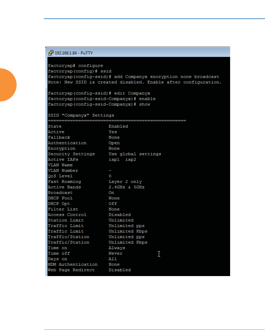
Wireless Access Point
498 The Command Line Interface
Configuring a Simple Open Global SSID
This example shows you how to configure a simple open global SSID.
Figure 217. Configuring a Simple Open Global SSID
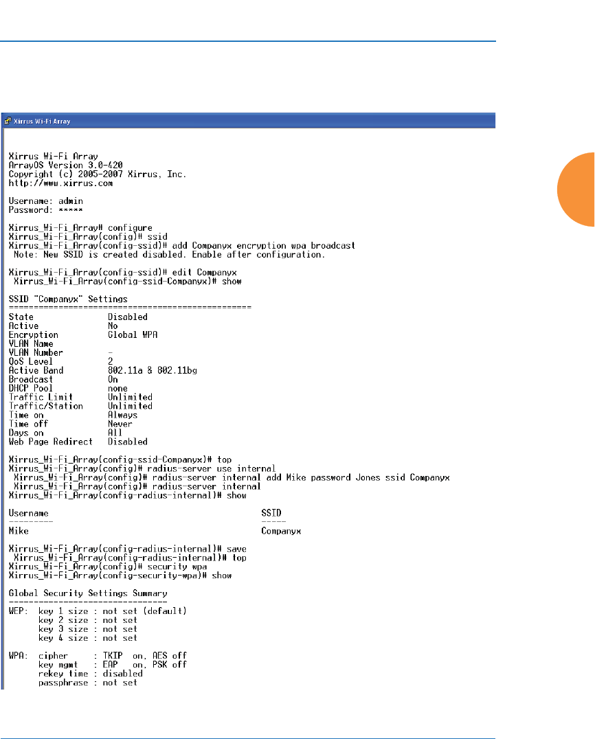
Wireless Access Point
The Command Line Interface 499
Configuring a Global SSID using WPA-PEAP
This example shows you how to configure a global SSID using WPA-PEAP
encryption in conjunction with the AP’s Internal RADIUS server.
Figure 218. Configuring a Global SSID using WPA-PEAP
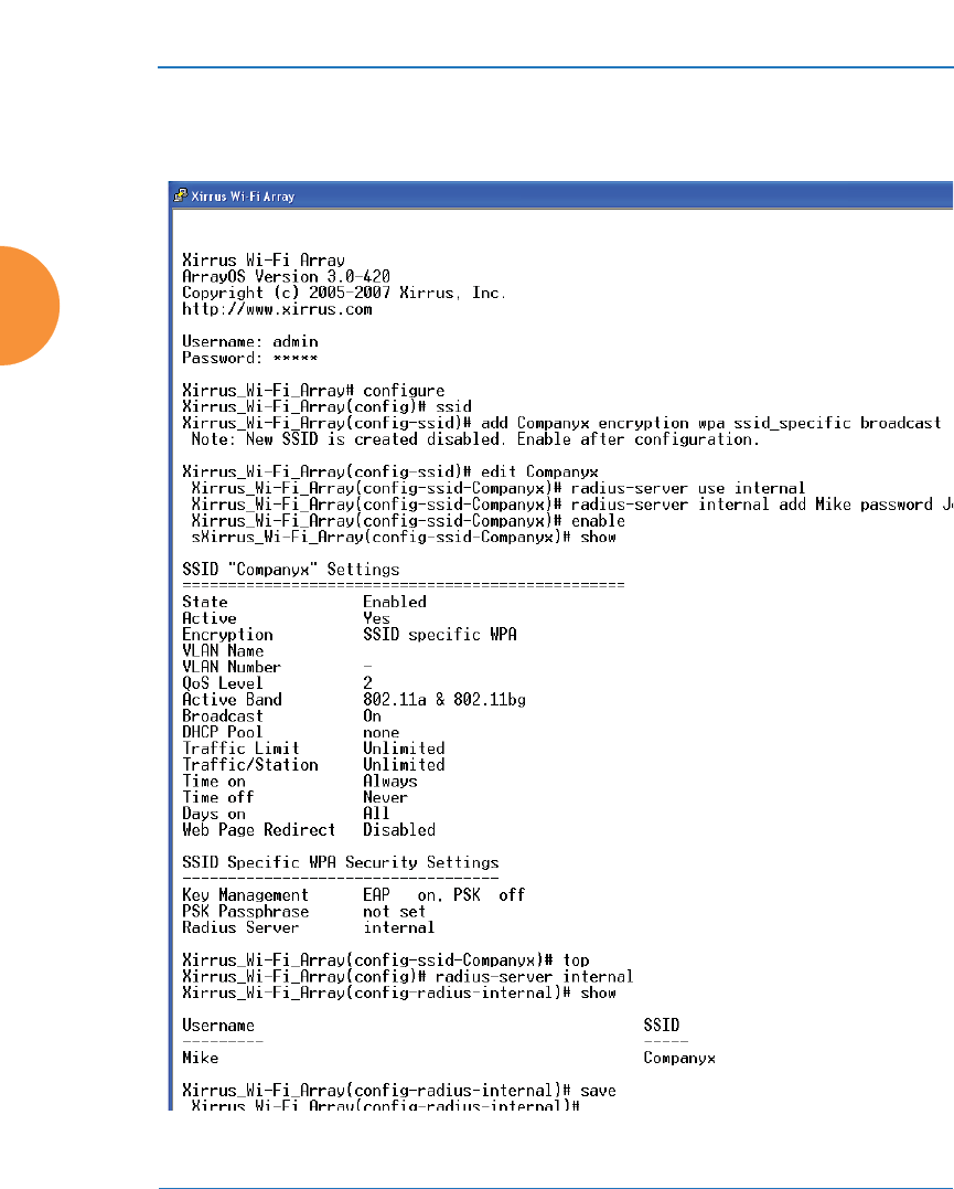
Wireless Access Point
500 The Command Line Interface
Configuring an SSID-Specific SSID using WPA-PEAP
This example shows you how to configure an SSID-specific SSID using WPA-
PEAP encryption in conjunction with the AP’s Internal RADIUS server.
Figure 219. Configuring an SSID-Specific SSID using WPA-PEAP
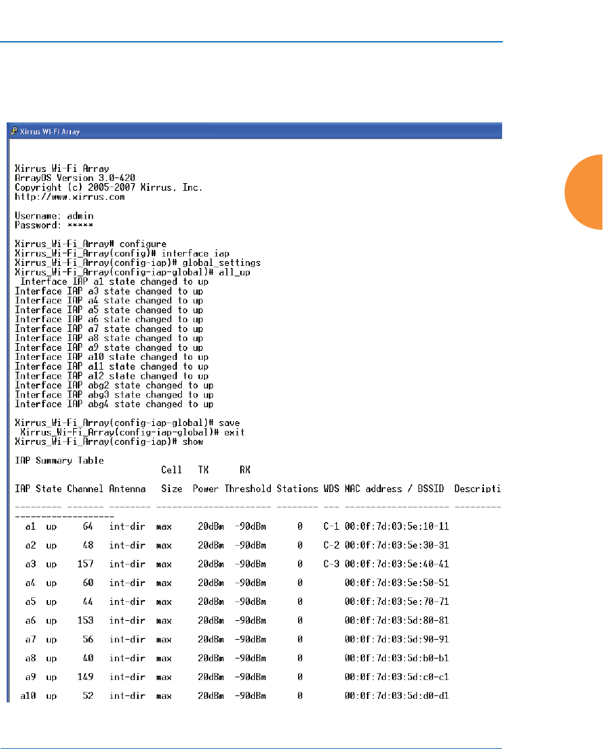
Wireless Access Point
The Command Line Interface 501
Enabling Global IAPs
This example shows you how to enable all IAPs (radios), regardless of the
wireless technology they use.
Figure 220. Enabling Global IAPs
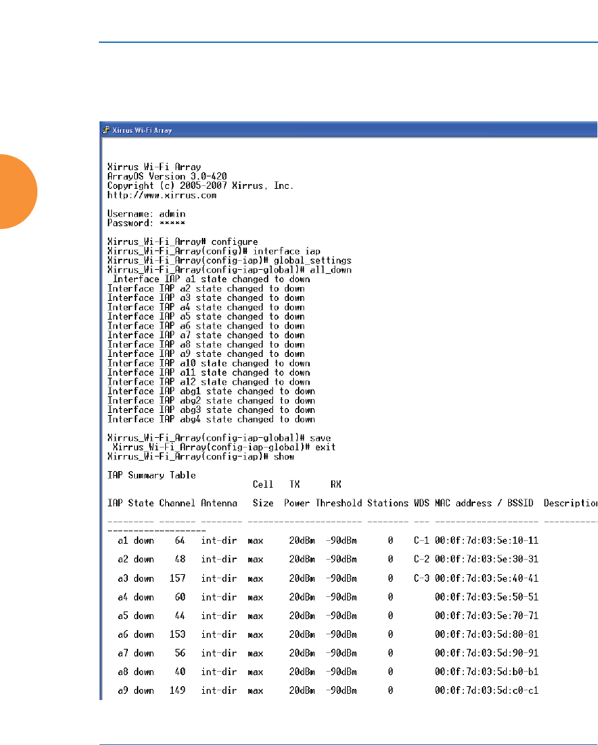
Wireless Access Point
502 The Command Line Interface
Disabling Global IAPs
This example shows you how to disable all IAPs (radios), regardless of the
wireless technology they use.
Figure 221. Disabling Global IAPs
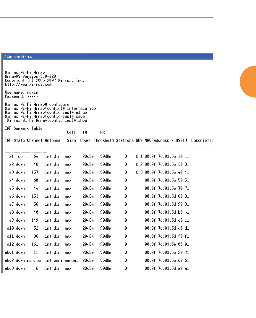
Wireless Access Point
The Command Line Interface 503
Enabling a Specific IAP
This example shows you how to enable a specific IAP (radio). In this example, the
IAP that is being enabled is a1 (the first IAP in the summary list).
Figure 222. Enabling a Specific IAP
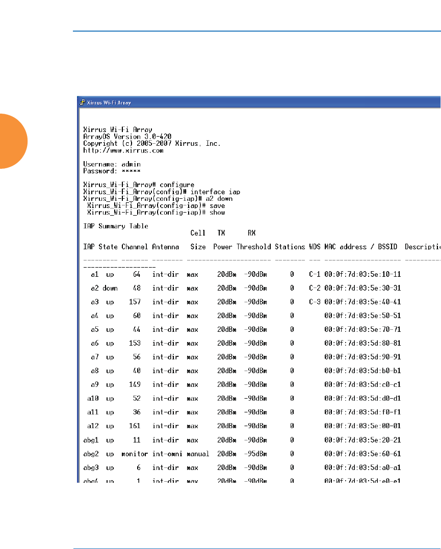
Wireless Access Point
504 The Command Line Interface
Disabling a Specific IAP
This example shows you how to disable a specific IAP (radio). In this example,
the IAP that is being disabled is a2 (the second IAP in the summary list).
Figure 223. Disabling a Specific IAP
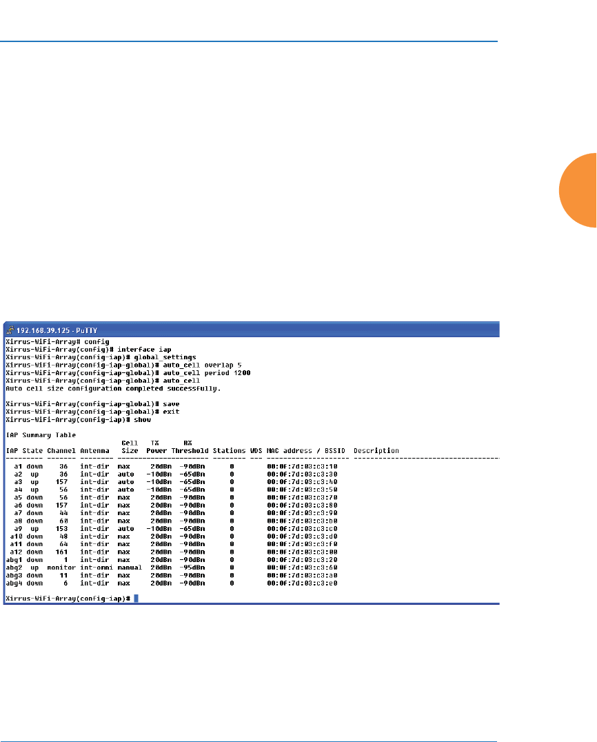
Wireless Access Point
The Command Line Interface 505
Setting Cell Size Auto-Configuration for All IAPs
This example shows how to set the cell size for all enabled IAPs to be auto-
configured (auto). (See “Fine Tuning Cell Sizes” on page 37.) The auto_cell option
may be used with global_settings, global_a_settings, or global_bg_settings. It
sets the cell size of the specified IAPs to auto, and it launches an auto-
configuration to adjust the sizes. Be aware that if the intrude-detect feature is
enabled on the monitor radio, its cell size is unaffected by this command. Also,
any IAPs used in WDS links are unaffected.
Auto-configuration may be set to run periodically at intervals specified by
auto_cell period (in seconds) if period is non-zero. The percentage of overlap
allowed between cells in the cell size computation is specified by auto_cell
overlap (0 to 100). This example sets auto-configuration to run every 1200 seconds
with an allowed overlap of 5%.
Figure 224. Setting Cell Size Auto-Configuration for All IAPs
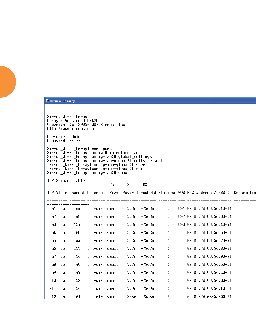
Wireless Access Point
506 The Command Line Interface
Setting the Cell Size for All IAPs
This example shows you how to establish the cell size for all IAPs (radios),
regardless of the wireless technology they use. Be aware that if the intrude-detect
feature is enabled on the monitor radio the cell size cannot be set globally — you
must first disable the intrude-detect feature on the monitor radio.
In this example, the cell size is being set to small for all IAPs. You have the option
of setting IAP cell sizes to small, medium, large, or max. See also, “Fine Tuning
Cell Sizes” on page 37.
Figure 225. Setting the Cell Size for All IAPs
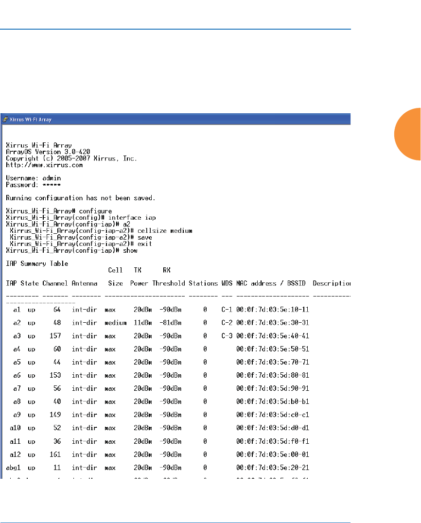
Wireless Access Point
The Command Line Interface 507
Setting the Cell Size for a Specific IAP
This example shows you how to establish the cell size for a specific IAP (radio). In
this example, the cell size for a2 is being set to medium. You have the option of
setting IAP cell sizes to small, medium, large, or max (the default is max). See
also, “Fine Tuning Cell Sizes” on page 37.
Figure 226. Setting the Cell Size for a Specific IAP
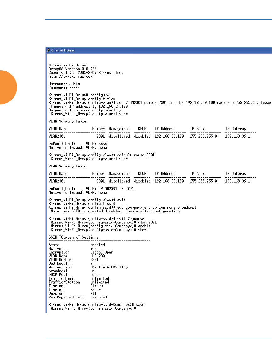
Wireless Access Point
508 The Command Line Interface
Configuring VLANs on an Open SSID
This example shows you how to configure VLANs on an Open SSID.
Figure 227. Configuring VLANs on an Open SSID
#Setting the default route
enables the AP to send
management traffic, such as
Syslog messages and SNMP
information to a destination
behind a router.

Wireless Access Point
The Command Line Interface 509
Configuring Radio Assurance Mode (Loopback Tests)
The AP uses its built-in monitor radio to monitor other radios in the AP. Tests
include sending probes on all channels and checking for a response, and checking
whether beacons are received from the other radio. If a problem is detected,
corrective actions are taken to recover. Loopback mode operation is described in
detail in “AP Monitor and Radio Assurance Capabilities” on page 529.
The following actions may be configured:
z
alert-only — the AP will issue an alert in the Syslog.
z
repair-without-reboot — the AP will issue an alert and reset radios at the
Physical Layer (Layer 1) and possibly at the MAC layer. The reset should
not be noticed by users, and they will not need to reassociate.
z
reboot-allowed — the AP will issue an alert, reset the radios, and
schedule the AP to reboot at midnight (per local AP time) if necessary. All
stations will need to reassociate to the AP.
z
off — Disable IAP loopback tests (no self-monitoring occurs). Radio
Assurance mode is off by default.
This is a global IAPs setting — the monitor radio will monitor all other radios
according to the settings above, and it cannot be set up to monitor particular
radios. Radio assurance mode requires Intrusion Detection to be set to Standard.
The following example shows you how to configure a loopback test.
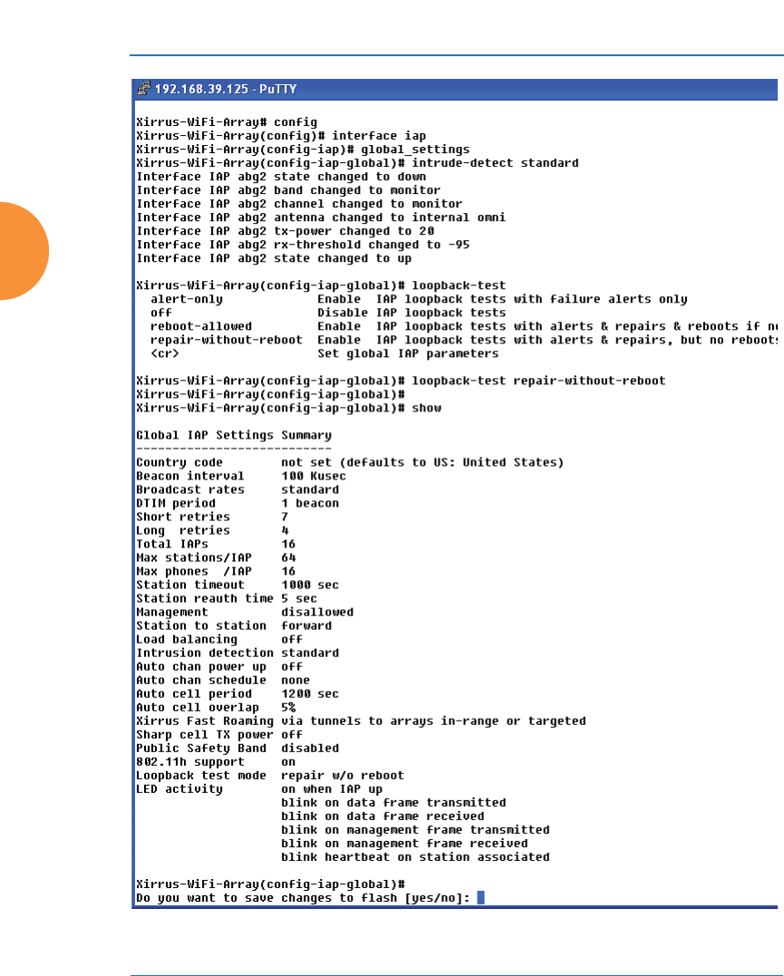
Wireless Access Point
510 The Command Line Interface
Figure 228. Configuring Radio Assurance Mode (Loopback Testing)

Wireless Access Point
Appendices 511
Appendices

Wireless Access Point
512 Appendices
Page is intentionally blank

Wireless Access Point
513
Appendix A: Quick Reference Guide
This section contains product reference information. Use this section to locate the
information you need quickly and efficiently. Topics include:
z
“Factory Default Settings” on page 513.
z
“Keyboard Shortcuts” on page 519.
Factory Default Settings
The following tables show the Wireless AP’s factory default settings.
Host Name
Network Interfaces
Serial
Setting Default Value
Host name Serial Number (e.g.,
XR4012802207C
Setting Default Value
Baud Rate 115200
Word Size 8 bits
Stop Bits 1
Parity No parity
Time Out 10 seconds

Wireless Access Point
514
Gigabit 1 and Gigabit 2
Server Settings
NTP
Syslog
Setting Default Value
Enabled Yes
DHCP Yes
Default IP Address 10.0.2.1
Default IP Mask 255.255.255.0
Default Gateway None
Auto Negotiate On
Duplex Full
Speed 1000 Mbps
MTU Size 1500
Management Enabled Yes
Setting Default Value
Enabled No
Primary time.nist.gov
Secondary pool.ntp.org
Setting Default Value
Enabled Yes

Wireless Access Point
515
SNMP
DHCP
Local Syslog Level Information
Maximum Internal Records 500
Primary Server None
Primary Syslog Level Information
Secondary Server None
Secondary Syslog Level Information
Setting Default Value
Enabled Yes
Read-Only Community String (v2) xirrus_read_only
Read-Write Community String (v2) xirrus
Read-Only Community String (v3) xirrus-ro
Read-Write Community String (v3) xirrus-rw
Trap Host null (no setting)
Trap Port 162
Authorization Fail Port On
Setting Default Value
Enabled No
Maximum Lease Time 300 minutes
Default Lease Time 300 minutes
Setting Default Value

Wireless Access Point
516
Default SSID
Security
Global Settings - Encryption
IP Start Range 192.168.1.4
IP End Range 192.168.1.254
NAT Disabled
IP Gateway None
DNS Domain None
DNS Server (1 to 3) None
Setting Default Value
ID xirrus
VLAN None
Encryption Off
Encryption Type None
QoS 2
Enabled Yes
Broadcast On
Setting Default Value
Enabled Yes
WEP Keys null (all 4 keys)
Setting Default Value

Wireless Access Point
517
External RADIUS (Global)
WEP Key Length null (all 4 keys)
Default Key ID 1
WPA Enabled No
TKIP Enabled Yes
AES Enabled Yes
EAP Enabled Yes
PSK Enabled No
Pass Phrase null
Group Rekey Disabled
Setting Default Value
Enabled Yes
Primary Server None
Primary Port 1812
Primary Secret null (no secret)
Secondary Server null (no IP address)
Secondary Port 1812
Secondary Secret null (no secret)
Time Out (before primary server is
retired) 600 seconds
Accounting Disabled
Interval 300 seconds
Setting Default Value

Wireless Access Point
518
Internal RADIUS
Administrator Account and Password
Management
Primary Server None
Primary Port 1813
Primary Secret null (no secret)
Secondary Server None
Secondary Port 1813
Secondary Secret null (no secret)
Setting Default Value
Enabled No
The user database is cleared upon reset to the factory defaults. For the
Internal RADIUS Server you have a maximum of 1,000 entries.
Setting Default Value
ID admin
Password admin
Setting Default Value
SSH On
SSH timeout 300 seconds
Setting Default Value

Wireless Access Point
519
Keyboard Shortcuts
The following table shows the most common keyboard shortcuts used by the
Command Line Interface.
Telnet Off
Telnet timeout 300 seconds
Serial On
Serial timeout 300 seconds
Management over IAPs Off
http timeout 300 seconds
Action Shortcut
Cut selected data and place it on the
clipboard. Ctrl + X
Copy selected data to the clipboard. Ctrl + C
Paste data from the clipboard into a
document (at the insertion point). Ctrl + V
Go to top of screen. Ctrl + Z
Copy the active window to the
clipboard. Alt + Print Screen
Copy the entire desktop image to the
clipboard. Print Screen
Abort an action at any time. Esc
Go back to the previous screen. b
Access the Help screen. ?
Setting Default Value

Wireless Access Point
520

Wireless Access Point
521
Appendix B: FAQ and Special Topics
This appendix provides valuable support information that can help you resolve
technical difficulties. Before contacting Xirrus, review all topics below and try to
determine if your problem resides with the Wireless AP or your network
infrastructure. Topics include:
z
“General Hints and Tips” on page 521
z
“Frequently Asked Questions” on page 522
z
“AP Monitor and Radio Assurance Capabilities” on page 529
z
“RADIUS Vendor Specific Attribute (VSA) for Xirrus” on page 532
z
“Location Service Data Formats” on page 533
z
“Upgrading the AP Using the Boot Loader” on page 537
General Hints and Tips
This section provides some useful tips that will optimize the reliability and
performance of your Wireless APs.
z
The Wireless AP requires careful handling. For best performance, units
should be mounted in a dust-free and temperature-controlled
environment.
z
If using multiple APs in the same area, maintain a distance of at least 100
feet (30m) between APs if there is direct line-of-sight between the units, or
at least 50 feet (15 m) if a wall or other barrier exists between the units.
z
Keep the Wireless AP away from electrical devices or appliances that
generate RF noise. Because the AP is generally mounted on ceilings, be
aware of its position relative to lighting (especially fluorescent lighting).
z
If you are deploying multiple units, the AP should be oriented so that the
monitor radio is oriented in the direction of the least required coverage,
because when in monitor mode the radio does not function as an AP
servicing stations.
z
The Wireless AP should only be used with Wi-Fi certified client devices.

Wireless Access Point
522
See Also
Multiple SSIDs
Security
VLAN Support
Frequently Asked Questions
This section answers some of the most frequently asked questions, organized by
functional area.
Multiple SSIDs
Q. What Are BSSIDs and SSIDs?
A. BSSID (Basic Service Set Identifier) refers to an individual access point
radio and its associated clients. The identifier is the MAC address of the
access point radio that forms the BSS.
A group of BSSs can be formed to allow stations in one BSS to
communicate to stations in another BSS by way of a backbone that
interconnects each access point.
The Extended Service Set (ESS) refers to the group of BSSIDs that are
grouped together to form one ESS. The ESSID (often referred to as SSID or
“wireless network name”) identifies the Extended Service Set. Clients
must associate to a single ESS at any given time. Clients ignore traffic
from other Extended Service Sets that do not have the same SSID.
Legacy access points typically support one SSID per access point. Xirrus
Wireless APs support the ability for multiple SSIDs to be defined and
used simultaneously.
Q. What would I use SSIDs for?
A. The creation of different wireless network names allows system
administrators to separate types of users with different requirements. The
following policies can be tied to an SSID:
z
Minimum security required to join this SSID.

Wireless Access Point
523
z
The wireless Quality of Service (QoS) desired for this SSID.
z
The wired VLAN associated with this SSID.
As an example, one SSID named accounting might require the highest
level of security, while another SSID named guests might have low
security requirements.
Another example may define an SSID named voice that supports voice
over Wireless LAN phones with the highest possible Quality of Service
(QoS) definition. This type of SSID might also forward traffic to specific
VLANs on the wired network.
Q. How do I set up SSIDs?
A. Use the following procedure as a guideline. For more detailed
information, go to “SSIDs” on page 268.
1. From the Web Management Interface, go to the SSID
Management page.
2. Select Yes to make the SSID visible to all clients on the network.
Although the Wireless AP will not broadcast SSIDs that are
hidden, clients can still associate to a hidden SSID if they know
the SSID name to connect to it.
3. Select the minimum security that will be required by users for
this SSID.
4. If desired (optional), select a Quality of Service (QoS) setting for
this SSID. The QoS setting you define here will prioritize wireless
traffic for this SSID over other SSID wireless traffic.
5. If desired (optional), select a VLAN that you want this traffic to
be forwarded to on the wired network.
6. If desired (optional), you can select which radios this SSID will
not be available on — the default is to make this SSID available on
all radios.
7. Click on the Save button if you wish to make your changes
permanent.

Wireless Access Point
524
8. If you need to edit any of the SSID settings, you can do so from
the SSID Management page.
See Also
General Hints and Tips
Security
SSIDs
SSID Management
VLAN Support
Security
Q. How do I ensure that I meet FIPS requirements?
A. To meet the Level 2 security requirements of FIPS 140-2, follow the
instructions in “Implementing FIPS Security” on page 591.
Q. How do I configure the AP for PCI DSS auditing?
A. A. To audit PCI DSS requirements, follow the instructions in “Auditing
PCI DSS” on page 585.
Q. How do I know my management session is secure?
A. Follow these guidelines:
z
Administrator passwords
Always change the default administrator password (the default
is admin), and choose a strong replacement password. When
appropriate, issue read only administrator accounts.
z
SSH versus Telnet
Be aware that Telnet is not secure over network connections and
should be used only with a direct serial port connection. When
connecting to the unit’s Command Line Interface over a network
connection, you must use a Secure SHell (SSH) utility. The most
commonly used freeware providing SSH tools is PuTTY. The AP
only allows SSH-2 connections, so your SSH utility must be set
up to use SSH-2.

Wireless Access Point
525
z
Configuration auditing
Do not change approved configuration settings. The optional
XMS offers powerful management features for small or large
Wireless AP deployments, and can audit your configuration
settings automatically. In addition, using the XMS eliminates the
need for an FTP server.
Q. Which wireless data encryption method should I use?
A. Wireless data encryption prevents eavesdropping on data being
transmitted or received over the airwaves. The Wireless AP allows you to
establish the following data encryption configuration options:
z
Open
This option offers no data encryption and is not recommended,
though you might choose this option if clients are required to use
a VPN connection through a secure SSH utility, like PuTTy.
z
Wired Equivalent Privacy (WEP)
This option provides minimal protection (though much better
than using an open network). An early standard for wireless data
encryption and supported by all Wi-Fi certified equipment, WEP
is vulnerable to hacking and is therefore not recommended for
use by Enterprise networks.
z
Wi-Fi Protected Access (WPA)
This is a much stronger encryption model than WEP and uses
TKIP (Temporal Key Integrity Protocol) with AES (Advanced
Encryption Standard) to prevent WEP cracks.
TKIP solves security issues with WEP. It also allows you to
establish encryption keys on a per-user-basis, with key rotation
for added security. In addition, TKIP provides Message Integrity
Check (MIC) functionality and prevents active attacks on the
wireless network.
AES is the strongest encryption standard and is used by
government agencies; however, old legacy hardware may not be
capable of supporting the AES mode (it probably won’t work on

Wireless Access Point
526
older wireless clients). Because AES is the strongest encryption
standard currently available, it is highly recommended for
Enterprise networks.
Any of the above encryption modes can be used (and can be used at
the same time).
Q. Which user authentication method should I use?
A. User authentication ensures that users are who they say they are. For
example, the most obvious example of authentication is logging in with a
user name and password. The Wireless AP allows you to choose between
the following user authentication methods:
z
Pre-Shared Key
Users must manually enter a key (pass phrase) on the client side
of the wireless network that matches the key stored by the
administrator in your Wireless APs.
z
RADIUS 802.1x with EAP
802.1x uses a RADIUS server to authenticate large numbers of
clients, and can handle different EAP (Extensible Authentication
Protocol) authentication methods, including EAP-TLS, EAP-
TTLS and EAP-PEAP. The RADIUS server can be internal
(provided by the Wireless AP) or external. An external RADIUS
server offers more functionality and is recommended for large
Enterprise deployments.
When using this method, user names and passwords must be
entered into the RADIUS server for user authentication.
z
MAC Address ACLs (Access Control Lists)
MAC address ACLs provide a list of client adapter MAC
addresses that are allowed or denied access to the wireless
network. Access Control Lists work well when there are a limited
#TKIP encryption does not support high throughput rates, per the
IEEE 802.11n.

Wireless Access Point
527
number of users — in this case, enter the MAC addresses of each
user in the Allow list. In the event of a lost or stolen MAC
adapter, enter the affected MAC address in the Deny list.
Q. Why do I need to authenticate my Wireless AP units?
A. When deploying multiple Wireless APs, you may need to define which
units are part of which wireless network (for example, if you are
establishing more than one network). In this case you need to employ the
XMS, which can authenticate your APs automatically and ensure that
only authorized units are associated with the defined wireless network.
Q. What is rogue AP (Access Point) detection?
A. The Wireless AP has integrated monitor capabilities, which can
constantly scan the local wireless environment for rogue APs (non-Xirrus
devices that are not part of your wireless network), unencrypted
transmissions, and other security issues. Administrators can then classify
each rogue AP and ensure that these devices do not interrupt or interfere
with the network.
See Also
General Hints and Tips
Multiple SSIDs
VLAN Support
VLAN Support
Q. What Are VLANs?
A. Virtual Local Area Networks (VLANs) are a logical grouping of network
devices that share a common network broadcast domain. Members of a
particular VLAN can be on any segment of the physical network but
logically only members of a particular VLAN can see each other.
VLANs are defined and implemented using the wired network switches
that are VLAN capable. Packets are tagged for transmission on a

Wireless Access Point
528
particular VLAN according to the IEEE 802.1Q standard, with VLAN
switches processing packets according to the tag.
Q. What would I use VLANs for?
A. Logically separating different types of users, systems, applications, or
other logical division aids in performance and management of different
network devices. Different VLANs can also be assigned with different
packet priorities to prioritize packets from one VLAN over packets from
another VLAN.
VLANs are managed by software settings — instead of physically
plugging in and moving network cables and users — which helps to ease
network management tasks.
Q. What are Wireless VLANs?
A. Wireless VLANs allow similar functionality to the wired VLAN
definitions and extend the operation of wired VLANs to the wireless side
of the network.
Wireless VLANs can be mapped to wireless SSIDs so that traffic from
wired VLANs can be sent to wireless users of a particular SSID. The
reverse is also true, where wireless traffic originating from a particular
SSID can be tagged for transmission on a particular wired VLAN.
Sixteen SSIDs can be defined on your AP, allowing a total of sixteen
VLANs to be accessed (one per SSID).
As an example, to provide guest user access an SSID of guest might be
created. This SSID could be mapped to a wired VLAN that segregates
unknown users from the rest of the wired network and restricts them to
Internet access only. Wireless users could then associate to the wireless
network via the guest SSID and obtain access to the Internet through the
selected VLAN, but would be unable to access other privileged network
resources.
See Also
General Hints and Tips
Multiple SSIDs

Wireless Access Point
529
AP Monitor and Radio Assurance Capabilities
All models of the Wireless AP have integrated monitoring capabilities to check
that the AP’s radios are functioning correctly, and act as a threat sensor to detect
and prevent intrusion from rogue access points.
Enabling Monitoring on the AP
Any radio may be set to monitor the AP or to be a normal radio. In order to enable
the functions required for intrusion detection and for monitoring the other AP
radios, you must configure one monitor radio on the IAP Settings window as
follows:
z
Check the Enabled checkbox.
z
Set Mode to Monitor.
z
Set Channel to Monitor.
The settings above will automatically set the Antenna selection to
Internal-Omni., also required for monitoring. See the “IAP Settings” on page 313
for more details. The values above are the factory default settings for the AP.
You must also enable RF Monitor Mode on the AP (either Timeshare or
Dedicated). See “Advanced RF Settings” on page 358.
How Monitoring Works
When the monitor radio has been configured as just described, it performs these
steps continuously (24/7) to check the other radios on the AP and detect possible
intrusions:
1. The monitor radio scans all channels with a 200ms dwell time, hitting all
channels about once every 10 seconds.
2. Each time it tunes to a new channel it sends out a probe request in an
attempt to smoke out rogues.
3. It then listens for all probe responses and beacons to detect any rogues
within earshot.
4. AP radios respond to that probe request with a probe response.

Wireless Access Point
530
Intrusion Detection is enabled or disabled separately from monitoring. See Step 1
in “Intrusion Detection” on page 373.
Radio Assurance
The AP is capable of performing continuous, comprehensive tests on its radios to
assure that they are operating properly. Testing is enabled using the Radio
Assurance Mode setting (see “Advanced RF Settings” on page 358). When this
mode is enabled, the monitor radio performs loopback tests on the AP. Radio
Assurance Mode requires Intrusion Detection to be set to Standard (See Step 1 in
“Intrusion Detection” on page 373).
When Radio Assurance Mode is enabled:
1. The AP keeps track of whether or not it hears beacons and probe
responses from the AP’s radios.
2. After 10 minutes (roughly 60 passes on a particular channel by the
monitor radio), if it has not heard beacons or probe responses from one of
the AP’s radios it issues an alert in the Syslog. If repair is allowed (see
“Radio Assurance Options” on page 531), the AP will reset and
reprogram that particular radio at the Physical Layer (PHY — Layer 1).
This action takes under 100ms and stations are not deauthenticated, thus
users should not be impacted.
3. After another 10 minutes (roughly another 60 passes), if the monitor still
has not heard beacons or probe responses from the malfunctioning radio
it will again issue an alert in the Syslog. If repair is allowed, the AP will
reset and reprogram the MAC (the lower sublayer of the Data Link Layer)
and then all of the PHYs. This is a global action that affects all radios. This
action takes roughly 300ms and stations are not deauthenticated, thus
users should not be impacted.
4. After another 10 minutes, if the monitor still has not heard beacons or
probe responses from that radio, it will again syslog the issue. If reboot is
allowed (see “Radio Assurance Options” on page 531), the AP will
schedule a reboot. This reboot will occur at one of the following times,
whichever occurs first:

Wireless Access Point
531
•When no stations are associated to the AP
•Midnight
Radio Assurance Options
If the monitor detects a problem with an AP radio as described above, it will take
action according to the preference that you have specified in the Radio Assurance
Mode setting on the Advanced RF Settings window (see Step 2):
z
Failure alerts only — The AP will issue alerts in the Syslog, but will not
initiate repairs or reboots.
z
Failure alerts & repairs, but no reboots — The AP will issue alerts and
perform resets of the PHY and MAC as described above.
z
Failure alerts & repairs & reboots if needed — The AP will issue alerts,
perform resets of the PHY and MAC, and schedule reboots as described
above.
z
Disabled — Disable loopback tests (no self-monitoring occurs). Loopback
tests are disabled by default.

Wireless Access Point
532
RADIUS Vendor Specific Attribute (VSA) for Xirrus
A RADIUS VSA is defined for Xirrus APs to control administrator privilege
settings for user accounts. The RADIUS VSA is used by APs to define the
following attribute for administrator accounts:
z
AP administrators — the Xirrus-Admin-Role attribute sets the privilege
level for this account. Set the value to the string defined in Privilege
Level Name as described in “About Creating Admin Accounts on the
RADIUS Server” on page 235.
Note that the VSA key (VENDOR value) for Xirrus is 21013:1.
dm Device Mfg
dt Device Type
dc Device Class
px Coordinate x
py Coordinate y
pz Coordinate z

Wireless Access Point
533
Location Service Data Formats
Xirrus APs are able to capture and upload visitor analytics data, acting as a sensor
network in addition to providing wireless connectivity. This data is sent to the
location server in different formats, based on the type of server. The Location
Server URL, Location Customer Key, and Location Period for reporting data are
configured under Location settings. See “Location” on page 191 for details. If a
Location Customer Key has been entered, data is sent encrypted using AES with
that key.
Euclid Location Server
If the Location Server URL contains the string euclid, then it specifies a Euclid
server. Data is sent at the specified intervals, in the proprietary format expected
by the Euclid location server.
Non-Euclid Location Server
If the Location Server URL doesn’t contain the string “euclid”, then data is sent as
a JSON object at the specified intervals, with the following fields.
Field Name Description
ln Location Name AP location string
ld Location Data Defined below
vn Version Number Set to 1
ma MAC Address Base IAP MAC Address
mc Message Count Running message count (resets to 0 when AP is
rebooted)
lt Location Table Table of Stations and APs heard during this
window
si Station ID Station MAC address (AES encrypted if cust-
key is not blank)

Wireless Access Point
534
bi BSSID BSSID that the station is on (AES encrypted if
cust-key is not blank). Only stations that are
associated to this AP will have a bi (BSSID)
field, i.e., for unassociated stations the bi
(BSSID) field will not be included.
sm Station OUI OUI of Station manufacturer (the top 3 bytes of
the MAC address that can be used to look up
the manufacturer), unencrypted ***
ap AP Flag 1=AP, 0=Station ***
dm Device Mfg Station manufacturer
dt Device Type Type of device, such as iPhone or Android ***
dc Device Class Category of device, such as phone or notebook
***
px Coordinate x These location coordinates are sent to the AP
by XMS-Enterprise. They appear only if the AP
has been placed on an XMS map. *
py Coordinate y
pz Coordinate z
cn Count Count of frames heard from device during this
window ***
ot Origin Time Timestamp of first frame in this window (Unix
time in seconds) ***
ct Current Time Timestamp of last frame in this window (Unix
time in seconds) ***
cf Current
Frequency Frequency (MHz) last frame was heard on ***
il Interval Low Minimum interval between frames (within 24
hr period) ***
ih Interval High Maximum interval between frames (within 24
hr period) ***
sl Signal Low Minimum signal strength (within 24 hr period)
***
Field Name Description

Wireless Access Point
535
* X, y, and z indicate the station location in terms of the number of pixels from the
top left (x=0, y=0, z=0) on the XMS map, where x and y are the horizontal and
vertical axes on the map, respectively, and z is typically the station’s distance
below the AP from the mounting site. The scale is the distance covered by a pixel
in feet or meters based on the map’s scale setting.
** Sample format with four radios receiving a station’s probe request:
"pr":{"00:0f:7d:44:03:20":-69,"00:0f:7d:44:03:30":-68,"00:0f:7d:44:03:40":-70,
"00:0f:7d:44:03:60":-60}
*** If the word xirrus is found in the URL, the AP assumes that you are using
location based services for stations, and reduces the size of messages by dropping
unneeded fields from the output. Specifically, the following fields will be dropped
from the output for each station:
In addition, with xirrus in the URL, only those stations whose RSSI (signal
strength) is highest when compared to the station’s RSSI at neighboring APs will
sh Signal High Maximum signal strength (within 24 hr period)
***
so Signal Origin Signal strength of first frame heard ***
sc Signal Current Signal strength of last frame heard
pr Probe Request For each radio hearing a probe request from a
station: BSSID of receiving radio and the
corresponding signal strength of last probe
heard for the station on that radio ** ***
ap (dropped for stations, but included for rogue APs)
dt ct sl
dc cf sh
sm il so
cn ih pr
ot
Field Name Description

Wireless Access Point
536
be sent. This also helps to minimize the number and size of messages, and largely
eliminates duplicate data being sent. Note that if a station’s RSSI is the same at
two or more APs, then they will all send data, so there is a chance of seeing
duplicates.

Wireless Access Point
537
Upgrading the AP Using the Boot Loader
If you are experiencing difficulties communicating with the AP using the Web
Management Interface, the AP provides lower-level facilities that may be used to
accomplish an upgrade via the Boot Loader (XBL).
1. Log in to your Xirrus customer support account and download the latest
software update. The software update is provided as a zip file. Unzip the
contents to a local temp directory. Take note of the extracted file name in
case you need it later on — you may also need to copy this file elsewhere
on the network depending on your situation.
2. Install a TFTP server software package if you don't have one running. It
may be installed on any computer on your network, including your
desktop or laptop. The Solar Winds version is freeware and works well.
http://www.solarwinds.com
The TFTP install process creates the TFTP-Root directory on your C:
drive, which is the default target for sending and receiving files. This may
be changed if desired. Place the extracted Xirrus software update file(s)
on this directory.
You must make the following change to the default configuration of the
Solar Winds TFTP server. In the File menu, select Configure, then select
the Security tab. Click Send files and click OK.
3. Determine the IP address of the computer hosting the TFTP server. (To
display the IP address, open a command prompt and type ipconfig)
4. Connect your AP to the computer running TFTP: a) if the AP has a
Console port, connect a serial cable to it and open a terminal program; or
b) use Xircon to communicate with the AP. Download Xircon and see the
#This procedure does not apply to Boot Loader versions 7000 or higher (these
recent versions are supplied with ArrayOS 7.3 and above). See “Access
Point Information” on page 102 to view the Boot Loader version on the AP.

Wireless Access Point
538
User’s Guide here. You may also find this useful: How can I access my AP
if it does not seem to be accessible via IP? How do I access an AP via
console or Xircon?
Attach a network cable to the AP’s Gig1 port, if it is not already part of
your network. Boot your AP and watch the progress messages. When
Press space bar to exit to bootloader: is displayed, press the space bar.
The rest of this procedure is performed using the bootloader.
The following steps assume that you are running DHCP on your local
network.
5. Type dhcp and hit return. This instructs the AP to obtain a DHCP address
and use it during this boot in the bootloader environment.
6. Type dir and hit return to see what's currently in the compact flash.
7. Type update server <TFTP-server-ip-addr> XS-7.x.x-xxxx.bin (the actual
file name will vary depending on AP model and software version — use
the file name from your software update) and hit return. The software
update will be transferred to the AP's memory and will be written to the
compact flash card. (See output below.)
8. Type dir and hit return to verify that the new image is in the compact
flash.
9. Type env set bootfile_active XS-7.x.x-xxxx.bin (the actual file name of the
new image) and hit return. This sets the new image to be the current
image—the image to load when the AP reboots.
10. Type env save and hit return to save the change you just made.
11. Type boot and hit return. Your AP will reboot, running your new version
of software.

Wireless Access Point
539
Sample Output for the Upgrade Procedure:
The user actions are highlighted in the output below, for clarity. Output will be in
the form shown below, but may not be exactly the same.
Username: admin
Password: *****
XR50326004F89# configure
XR50326004F89(config)# reboot
Are you sure you want to reboot? [yes/no]: yes
Array is being rebooted...
Sending trap .... done
Rebooting ...
Xirrus Boot Loader 6.3.0-6171 (Dec 11 2014 - 15:41:48)
Board | Xirrus CN5020-CP CPU Board
Clocks | CPU : 300 MHz DDR : 666 MHz
I2C Bus | 384 KHz, sampling at 11 MHz
Reset | Reset requested
Watchdog | Enabled (5 secs)
System DDR | 512 MB, DDR2 Unbuffered non-ECC
FLASH | 2 MB, CRC: OK
RTC | Fri 2014-Dec-12 19:40:11 GMT
CPU BIST | pass
PCI | PCI 32-bit, BAR 0: 0x08000000
Radios | 0 1
Network | eth0
USB | 1 Storage Device found
Environment | Initialized
In: ser_xc
Out: ser_xc
Err: ser_xc
Press space bar to exit to bootloader: 0

Wireless Access Point
540
Username: admin
Password: *****
XBL>dhcp
[DHCP ] Device : eth0 - 1000 Mbps Full Duplex
[DHCP ] IP Addr : 10.100.44.48
XBL>dir
[USB 0 ] Directory of /
Date Time Size File or Directory name
----------- -------- ---------- ---------------------------
2014-Dec-12 18:47:16 17776 factory.conf
2014-Dec-12 19:39:42 17810 lastboot.conf
2014-Dec-12 19:37:56 17810 saved.conf
2014-Dec-11 23:57:16 ssl/
2014-Dec-11 23:57:16 wmi/
2014-Dec-12 19:35:18 history/
2014-Dec-12 18:49:12 storage/
2014-Dec-12 18:46:28 wpr/
2014-Dec-12 19:39:20 tmp/
2014-Dec-12 18:41:28 77993740 XS-7.1.2-5152.bin
2014-Dec-12 19:38:14 29 lastboot.old
2014-Dec-12 19:38:58 29 lastboot
2014-Dec-12 18:47:26 proxy-client/
6 file(s), 7 dir(s)
XBL>update server 10.100.44.44 XS-7.2.3-5452.bin
[TFTP ] Device : eth0 - 1000 Mbps Full Duplex
[TFTP ] Client : 10.100.44.48
[TFTP ] Server : 10.100.44.44
[TFTP ] File : XS-7.2.3-5452.bin
[TFTP ] Address : 0x6000000
[TFTP ] Loading : ##################################################

Wireless Access Point
541
[TFTP ] Loading : ################################################ done
[TFTP ] Complete: 7.4 sec, 10.1 MB/sec
[TFTP ] Bytes : 78027656 (4a69b88 hex), 10226 Kbytes/sec
[USB 0 ] File : XS-7.2.3-5452.bin
[USB 0 ] Address : 0x6000000
[USB 0 ] Saving : ##################################################
[USB 0 ] Saving : ##################################################
[USB 0 ] Saving : ##################################################
[USB 0 ] Saving : ##################################################
[USB 0 ] Saving : ##################################################
[USB 0 ] Saving : ############################################## done
[USB 0 ] Complete: 59.5 sec, 1.3 MB/sec
[USB 0 ] Bytes : 78027656 (4a69b88 hex)
XBL>dir
[USB 0 ] Directory of /
Date Time Size File or Directory name
----------- -------- ---------- ---------------------------
2014-Dec-12 18:47:16 17776 factory.conf
2014-Dec-12 19:39:42 17810 lastboot.conf
2014-Dec-12 19:37:56 17810 saved.conf
2014-Dec-11 23:57:16 ssl/
2014-Dec-11 23:57:16 wmi/
2014-Dec-12 19:35:18 history/
2014-Dec-12 18:49:12 storage/
2014-Dec-12 18:46:28 wpr/
2014-Dec-12 19:39:20 tmp/
2014-Dec-12 18:41:28 77993740 XS-7.1.2-5152.bin
2014-Dec-12 19:38:14 29 lastboot.old
2014-Dec-12 19:38:58 29 lastboot
2014-Dec-12 18:47:26 proxy-client/
2014-Dec-12 19:41:22 78027656 XS-7.2.3-5452.bin
7 file(s), 7 dir(s)
XBL>env set bootfile_active XS-7.2.3-5452.bin
XBL>env save

Wireless Access Point
542
[Flash ] Saving : Environment 4 KB
XBL>boot
[USB 0 ] File : XS-7.2.3-5452.bin
[USB 0 ] Address : 0x6000000
[USB 0 ] Loading : ##################################################
[USB 0 ] Loading : ################################################ done
[USB 0 ] Complete: 6.5 sec, 11.4 MB/sec
[USB 0 ] Bytes : 78027656 (4a69b88 hex)
[Boot ] Address : 0x06000000
[Image ] Name : XR-7.2.3-5452
[Image ] Created : 2014-11-13 7:52:39 UTC
[Image ] Type : MIPS Linux Multi-File Image (uncompressed)
[Image ] Size : 78027552 Bytes = 74.4 MB
[Image ] Contents: File 0: 17248885 Bytes = 16.4 MB
[Image ] Contents: File 1: 49149529 Bytes = 46.9 MB
[Image ] Contents: File 2: 11629116 Bytes = 11.1 MB
[Boot ] Image : Verifying image ....... OK
[Boot ] Loading : Multi-File Image .... OK
[Boot ] Watchdog: Disabling .... OK
[Boot ] Execute : Transferring control to OS
Initializing hardware ............ OK
Xirrus Wi-Fi Array
ArrayOS Version 7.2.3-5452
Copyright (c) 2005-2014 Xirrus, Inc.
http://www.xirrus.com
Username:

Wireless Access Point
543
Appendix C: Notices (XD and XR500/600
Series Only)
This appendix contains the following information:
z
“Notices” on page 543
z
“EU Directive 1999/5/EC Compliance Information” on page 549
z
“Compliance Information (Non-EU)” on page 556
z
“Safety Warnings” on page 557
z
“Translated Safety Warnings” on page 558
z
“Software License and Product Warranty Agreement” on page 559
z
“Hardware Warranty Agreement” on page 559
Notices
Wi-Fi Alliance Certification
www.wi-fi.org
FCC Notice
This equipment has been tested and found to comply with the limits for a Class B
digital device, pursuant to Part 15 of the FCC rules. These limits are designed to
provide reasonable protection against harmful interference in a residential
installation. This equipment generates, uses and can radiate RF energy and, if not
#This Appendix contains Notices, Warnings, and Compliance information for
the XD and XR500/600 Series only.
For Notices, Warnings, and Compliance information for outdoor products,
please see the Quick Installation Guide for that product.
For Notices, Warnings, and Compliance information for all other APs,
please see “Notices (XR-1000 to XR-6000 Indoor Models)” on page 561.

Wireless Access Point
544
installed and used in accordance with the instructions, may cause harmful
interference to radio communications. However, there is no guarantee that
interference will not occur in a particular installation. If this equipment does
cause harmful interference to radio or television reception, which can be
determined by turning the equipment off and on, the user is encouraged to try to
correct the interference by one or more of the following safety measures:
z
Reorient or relocate the receiving antenna.
z
Increase the separation between the equipment and the receiver.
z
Connect the equipment into an outlet on a circuit different from that to
which the receiver is connected.
z
Consult the dealer or an experienced wireless technician for help.
This device complies with Part 15 of the FCC Rules, with operation subject to the
following two conditions: (1) This device may not cause harmful interference, and
(2) this device must accept any interference received, including interference that
may cause unwanted operation.
For XD2 models available in the USA/Canada market, only channels 1~11 can be
operated in the 2.4GHz band. Selection of other channels is not possible.
This device and its antenna(s) must not be co-located or operating in conjunction
with any other antenna or transmitter except in accordance with FCC multi-
transmitter product procedures.
This device is restricted for indoor use.
Use of a shielded twisted pair (STP) cable must be used for all Ethernet
connections in order to comply with EMC requirements.
Operations in the 5.15-5.25GHz band are restricted to indoor usage only.
IMPORTANT NOTE: FCC Radiation Exposure Statement
This equipment complies with FCC radiation exposure limits set forth for an
uncontrolled environment. To ensure compliance with FCC and Industry Canada
!FCC Caution: Any changes or modifications not expressly approved by the
party responsible for compliance could void the user's authority to operate this
equipment.

Wireless Access Point
545
RF exposure requirements, this device must be installed in a location where the
antennas of the device will have a minimum distance of at least 30 cm (12 inches)
from all persons, except that XD2 models must have a minimum distance of at
least 20 cm (8 inches) from all persons. Using higher gain antennas and types of
antennas not certified for use with this product is not allowed. The device shall
not be co-located with another transmitter.
High Power Radars
High power radars are allocated as primary users (meaning they have priority) in
the 5250MHz to 5350MHz and 5650MHz to 5850MHz bands. These radars could
cause interference and/or damage to LE-LAN devices.
Non-Modification Statement
Unauthorized changes or modifications to the device are not permitted. Use only
the supplied internal antenna, or external antennas supplied by the manufacturer.
Modifications to the device will void the warranty and may violate FCC
regulations.
Cable Runs for Power over Ethernet (PoE)
If using PoE, the AP must be connected to PoE networks without routing cabling
to the outside plant — this ensures that cabling is not exposed to lightning strikes
or possible cross over from high voltage.
Battery Warning
UL Statement
Use only with listed ITE product.
!Caution! The AP contains a battery which is not to be replaced by the customer.
Danger of Explosion exists if the battery is incorrectly replaced. Replace only with
the same or equivalent type recommended by the manufacturer. Dispose of used
batteries according to the manufacturer's instructions.

Wireless Access Point
546
Industry Canada Statement (XD Series)
This device complies with Industry Canada license-exempt RSS standards (RSS
247), and standards for Digital Transmission Systems (DTSs), Frequency Hopping
Systems (FHSs) and License-Exempt Local Area Network (LE-LAN) Devices.
Operation is subject to the following two conditions: (1) this device may not cause
interference, and (2) this device must accept any interference, including
interference that may cause undesired operation of the device.
Le présent appareil est conforme aux CNR d'Industrie Canada applicables aux appareils
radio exempts de licence. L'exploitation est autorisée aux deux conditions suivantes: (1)
l'appareil ne doit pas produire de brouillage, et (2) l'utilisateur de l'appareil doit accepter
tout brouillage radioélectrique subi, même si le brouillage est susceptible d'en
compromettre le fonctionnement.
For product available in the USA/Canada market, only channel 1~11 can be
operated. Selection of other channels is not possible.
Pour les produits disponibles aux États-Unis / Canada du marché, seul le canal 1 à 11
peuvent être exploités. Sélection d'autres canaux n'est pas possible.
This device and its antenna(s) must not be co-located or operating in conjunction
with any other antenna or transmitter except in accordance with IC multi-
transmitter product procedures.
Cet appareil et son antenne (s) ne doit pas être co-localisés ou fonctionnement en
association avec une autre antenne ou transmetteur.
Dynamic Frequency Selection (DFS) for devices operating in the bands 5250- 5350
MHz, 5470-5600 MHz and 5650-5725 MHz
Sélection dynamique de fréquences (DFS) pour les dispositifs fonctionnant dans les
bandes 5250-5350 MHz, 5470-5600 MHz et 5650-5725 MHz
The device for operation in the band 5150-5250 MHz is only for indoor use to
reduce the potential for harmful interference to co-channel mobile satellite
systems.
Les dispositifs fonctionnant dans la bande 5150-5250 MHz sont réservés uniquement
pour une utilisation à l'intérieur afin de réduire les risques de brouillage préjudiciable aux
systèmes de satellites mobiles utilisant les mêmes canaux.

Wireless Access Point
547
Users should also be advised that high-power radars are allocated as primary
users (i.e. priority users) of the bands 5250-5350 MHz and 5650-5850 MHz and
that these radars could cause interference and/or damage to LE-LAN devices.
De plus, les utilisateurs devraient aussi être avisés que les utilisateurs de radars de haute
puissance sont désignés utilisateurs principaux (c.-à-d., qu'ils ont la priorité) pour les
bandes 5250-5350 MHz et 5650-5850 MHz et que ces radars pourraient causer du
brouillage et/ou des dommages aux dispositifs LAN-EL.
For indoor use only.
Pour une utilisation en intérieur uniquement.
IMPORTANT NOTE:
IC Radiation Exposure Statement:
This equipment complies with IC RSS-102 radiation exposure limits set forth for
an uncontrolled environment. This equipment should be installed and operated
with minimum distance 20 cm between the radiator and your body.
Cet équipement est conforme aux limites d'exposition aux rayonnements IC établies pour
un environnement non contrôlé. Cet équipement doit être installé et utilisé avec un
minimum de 20 cm de distance entre la source de rayonnement et votre corps.
Industry Canada Statement (non-XD Series)
This device complies with RSS-210 of the Industry Canada Rules. Operation is
subject to the following two conditions: (1) This device may not cause harmful
interference, and (2) this device must accept any interference received, including
interference that may cause undesired operation.
Ce dispositif est conforme à la norme CNR-210 d'Industrie Canada applicable aux
appareils radio exempts de licence. Son fonctionnement est sujet aux deux conditions
suivantes: (1) le dispositif ne doit pas produire de brouillage préjudiciable, et (2) ce
dispositif doit accepter tout brouillage reçu, y compris un brouillage susceptible de
provoquer un fonctionnement indésirable.
Caution:
(i) the device for operation in the band 5150-5250 MHz is only for indoor use to
reduce the potential for harmful interference to co-channel mobile satellite
systems;

Wireless Access Point
548
(ii) high-power radars are allocated as primary users (i.e. priority users) of the
bands 5250-5350 MHz and 5650-5850 MHz and that these radars could cause
interference and/or damage to LE-LAN devices.
When operating the XR-600 Series in the band 5250-5350 MHz with a maximum
e.i.r.p. greater than 200 mW in Canada, please adjust antenna/EUT to comply
with the following e.i.r.p. elevation mask, where ș is the angle above the local
horizontal plane (of the Earth) as shown below:
(i) -13 dB(W/MHz) for 0° ș < 8°
(ii) -13 - 0.716 (ș-8) dB(W/MHz) for 8° ș < 40°
(iii) -35.9 - 1.22 (ș-40) dB(W/MHz) for 40° ș 45°
(iv) -42 dB(W/MHz) for ș > 45°
Avertissement:
(i) les dispositifs fonctionnant dans la bande 5 150-5 250 MHz sont réservés uniquement
pour une utilisation à l'intérieur afin de réduire les risques de brouillage préjudiciable aux
systèmes de satellites mobiles utilisant les mêmes canaux;
(ii) De plus, les utilisateurs devraient aussi être avisés que les utilisateurs de radars de
haute puissance sont désignés utilisateurs principaux (c.-à-d., qu'ils ont la priorité) pour
les bandes 5 250-5 350 MHz et 5 650-5 850 MHz et que ces radars pourraient causer du
brouillage et/ou des dommages aux dispositifs LAN-EL.
IMPORTANT NOTE:
IC Radiation Exposure Statement:
To ensure compliance with Industry Canada RF exposure requirements, this
device must be installed in a location where the antennas of the device will have a
minimum distance of at least 30 cm (12 inches) from all persons. Using higher
gain antennas and types of antennas not certified for use with this product is not
allowed. The device shall not be co-located with another transmitter.
Installez l'appareil en veillant à conserver une distance d'au moins 30 cm entre les
éléments rayonnants et les personnes. Cet avertissement de sécurité est conforme aux
limites d'exposition définies par la norme CNR-102 at relative aux fréquences radio.

Wireless Access Point
549
EU Directive 1999/5/EC Compliance Information
This section contains compliance information for the Xirrus Wireless AP family of
products. The compliance information contained in this section is relevant to the
European Union and other countries that have implemented the EU Directive
1999/5/EC.
Declaration of Conformity
#This Appendix contains Notices, Warnings, and Compliance information for
the XD and XR500/600 Series only. For other models, see the notes at the
beginning of this appendix.
Cesky [Czech] Toto zahzeni je v souladu se základnimi požadavky a
ostatnimi odpovidajcimi ustano veni mi SmČrnice
1999/5/EC.
Dansk [Danish] Dette udstyr er i overensstemmelse med de
væsentlige krav og andre relevante bestemmelser i
Direktiv 1999/5/EF.
Deutsch [German] Dieses Gerat entspricht den grundlegenden
Anforderungen und den weiteren entsprechenden
Vorgaben der Richtinie 1999/5/EU.
Eesti [Estonian] See seande vastab direktiivi 1999/5/EU olulistele
nöuetele ja teistele as jakohastele sätetele.
English This equipment is in compliance with the essential
requirements and other relevant provisions of
Directive 1999/5/EC.
Español [Spain] Este equipo cump le con los requisitos esenciales asi
como con otras disposiciones de la Directiva 1999/5/
CE.
ǼȜȜȘȞȣțȘ [Greek] ǹȣIJȩȗ Ƞ İȟȠʌȜIJıȝȩȗ İȓȞĮȚ ıİ ıȣȝȝȩȡijȦıȘ ȝİ IJȚȗ
ȠȣıȚȫįİȚȗ ĮʌĮȚIJȒıİȚȗ țĮȚ ȪȜȜİȗ ıȤİIJȚțȑȗ įȚĮIJȐȟİȚȗ IJȘȗ
ȅįȘȖȚĮȗ 1999/5/EC.

Wireless Access Point
550
Français [French] Cet appareil est conforme aux exigences essentielles
et aux autres dispositions pertinentes de la Directive
1999/5/EC.
Ďslenska [Icelandic] Þetta tæki er samkvæmt grunnkröfum og öðrum
viðeigandi ákvæðum Tilskipunar 1999/5/EC.
Italiano [Italian] Questo apparato é conforme ai requisiti essenziali ed
agli altri principi sanciti dalla Direttiva 1999/5/CE.
Latviski [Latvian] ŠƯ iekƗrta atbilst DirektƯvas 1999/5/EK bnjtiskajƗ
prasƯbƗm un citiem ar to saistƯtajiem noteikumiem.
Lietuviǐ [Lithuanian] Šis Ƴrenginys tenkina 1995/5/EB Direktyvos
esminius reikalavimus ir kitas šios direktyvos
nuostatas.
Nederlands [Dutch] Dit apparant voldoet aan de essentiele eisen en
andere van toepassing zijnde bepalingen van de
Richtlijn 1995/5/EC.
Malti [Maltese] Dan l-apparant huwa konformi mal-htigiet essenzjali
u l-provedimenti l-ohra rilevanti tad-Direttiva 1999/
5/EC.
Margyar [Hungarian] Ez a készülék teljesiti az alapvetö követelményeket
és más 1999/5/EK irányelvben meghatározott
vonatkozó rendelkezéseket.
Norsk [Norwegian] Dette utstyret er i samsvar med de grunnleggende
krav og andre relevante bestemmelser i EU-direktiv
1999/5/EF.
Polski [Polish] Urządzenie jest zgodne z ogólnymi wymaganiami
oraz sczególnymi mi warunkami okreĞlony mi
Dyrektywą. UE:1999/5/EC.
Portuguès [Portuguese] Este equipamento está em conformidade com os
requisitos essenciais e outras provisões relevantes da
Directiva 1999/5/EC.

Wireless Access Point
551
Assessment Criteria
The following standards were applied during the assessment of the product
against the requirements of the Directive 1999/5/EC:
z
Radio: EN 301 893 and EN 300 328 (if applicable)
z
EMC: EN 301 489-1 and EN 301 489-17
z
Safety: EN 60950, EN 62311 and EN 50385
CE Marking
For the Xirrus Wireless AP, the CE mark and Class-2 identifier opposite are
affixed to the equipment and its packaging:
Russian Certification Marking
For the Xirrus XR-500, XR-520H, XR-2000, and XR-4000 Series Wireless APs, the
approval mark is affixed to the equipment:
Slovensko [Slovenian] Ta naprava je skladna z bistvenimi zahtevami in
ostalimi relevantnimi popoji Direktive 1999/5/EC.
Slovensky [Slovak] Toto zariadenie je v zhode so základnými
požadavkami a inými prislušnými nariadeniami
direktiv: 1999/5/EC.
Suomi [Finnish] Tämä laite täyttää direktiivin 1999/5//EY olennaiset
vaatimukset ja on siinä asetettujen muiden laitetta
koskevien määräysten mukainen.
Svenska [Swedish] Denna utrustning är i överensstämmelse med de
väsentliga kraven och andra relevanta bestämmelser
i Direktiv 1999/5/EC.

Wireless Access Point
552
WEEE Compliance
zNatural resources were used in the production of
this equipment.
zThis equipment may contain hazardous
substances that could impact the health of the
environment.
zIn order to avoid harm to the environment and
consumption of natural resources, we encourage
you to use appropriate take-back systems when
disposing of this equipment.
zThe appropriate take-back systems will reuse or
recycle most of the materials of this equipment in
a way that will not harm the environment.
zThe crossed-out wheeled bin symbol (in
accordance with European Standard EN 50419)
invites you to use those take-back systems and
advises you not to combine the material with
refuse destined for a land fill.
zIf you need more information on collection, re-
use and recycling systems, please contact your
local or regional waste administration.
zPlease contact Xirrus for specific information on
the environmental performance of our products.

Wireless Access Point
553
National Restrictions
In the majority of the EU and other European countries, the 2.4 GHz and 5 GHz
bands have been made available for the use of Wireless LANs. The following table
provides an overview of the regulatory requirements in general that are
applicable for the 2.4 GHz and 5 GHz bands.
*Dynamic frequency selection and Transmit Power Control is required in these
frequency bands.
**France is indoor use only in the upper end of the band.
The requirements for any country may change at any time. Xirrus recommends
that you check with local authorities for the current status of their national
regulations for both 2.4 GHz and 5 GHz wireless LANs.
The following countries have additional requirements or restrictions than those
listed in the above table:
Belgium
The Belgian Institute for Postal Services and Telecommunications (BIPT) must
be notified of any outdoor wireless link having a range exceeding 300 meters.
Xirrus recommends checking at www.bipt.be for more details.
Draadloze verbindingen voor buitengebruik en met een reikwijdte van meer dan 300
meter dienen aangemeld te worden bij het Belgisch Instituut voor postdiensten en
telecommunicatie (BIPT). Zie www.bipt.be voor meer gegevens.
Frequency
Band (MHz) Max Power Level
(EIRP) (mW) Indoor Outdoor
2400–2483.5 100 X X **
5250–5350 *200 X N/A
5470–5725* 1000 X X

Wireless Access Point
554
Les liasons sans fil pour une utilisation en extérieur d’une distance supérieure à 300
mèters doivent être notifiées à l’Institut Belge des services Postaux et des
Télécommunications (IBPT). Visitez www.bipt.be pour de plus amples détails.
Greece
A license from EETT is required for the outdoor operation in the 5470 MHz to
5725 MHz band. Xirrus recommends checking www.eett.gr for more details.
Ǿ įȘ ȚȠȣȡȖȕȐȚțIJ ȦȞİȟȦIJİȡȚțȠ ȡȠȣıIJȘ ȗ ȞȘıȣ ȞȠIJ IJȦȞ 5470–5725 ȂǾz İ ȚIJȡ İIJȐȚȦȞȠ
İIJȐȐ ȩȐįİȚȐ IJȘȢ ǼǼȉȉ, Ƞȣ ȠȡȘȖİȕIJȐȚ ıIJİȡȐ Ȑ ȩ ı ijȦȞȘ ȖȞ Ș IJȠȣ īǼǼĬǹ. İȡȚııȩIJİȡİȢ
Ȝİ IJȠȝ ȡİȚİȦıIJȠ www.eett.gr
Italy
This product meets the National Radio Interface and the requirements
specified in the National Frequency Allocation Table for Italy. Unless this
wireless LAN product is operating within the boundaries of the owner’s
property, its use requires a “general authorization.” Please check with
www.communicazioni.it/it/ for more details.
Questo prodotto é conforme alla specifiche di Interfaccia Radio Nazionali e rispetta il
Piano Nazionale di ripartizione delle frequenze in Italia. Se non viene installato
all’interno del proprio fondo, l’utilizzo di prodotti wireless LAN richiede una
“autorizzazione Generale.” Consultare www.communicazioni.it/it/ per maggiori
dettagli.
Norway, Switzerland and Liechtenstein
Although Norway, Switzerland and Liechtenstein are not EU member states,
the EU Directive 1999/5/EC has also been implemented in those countries.
Calculating the Maximum Output Power
The regulatory limits for maximum output power are specified in EIRP (radiated
power). The EIRP level of a device can be calculated by adding the gain of the
antenna used (specified in dBi) to the output power available at the connector
(specified in dBm).

Wireless Access Point
555
Antennas
The Xirrus Wireless AP employs integrated antennas that cannot be removed and
which are not user accessible. Nevertheless, as regulatory limits are not the same
throughout the EU, users may need to adjust the conducted power setting for the
radio to meet the EIRP limits applicable in their country or region. Adjustments
can be made from the product’s management interface — either Web Management
Interface (WMI) or Command Line Interface (CLI).
Operating Frequency
The operating frequency in a wireless LAN is determined by the access point. As
such, it is important that the access point is correctly configured to meet the local
regulations. See National Restrictions in this section for more information.
If you still have questions regarding the compliance of Xirrus products or you
cannot find the information you are looking for, please contact us at:
Xirrus, Inc.
2101 Corporate Center Drive
Thousand Oaks, CA 91320
USA
Tel: 1.805.262.1600
1.800.947.7871 Toll Free in the US
Fax: 1.866.462.3980
www.xirrus.com

Wireless Access Point
556
Compliance Information (Non-EU)
This section contains compliance information for the Xirrus Wireless AP family of
products. The compliance information contained in this section is relevant to the
listed countries (outside of the European Union and other countries that have
implemented the EU Directive 1999/5/EC).
Declaration of Conformity—Brazil
#This Appendix contains Notices, Warnings, and Compliance information for
the XD and XR500/600 Series only. For other models, see the notes at the
beginning of this appendix.
For XR-500 Only

Wireless Access Point
557
Declaration of Conformity
Safety Warnings
Mexico XR-520: Dictamen #: 1402D00742
XR-600: Dictamen #: 1402CE08098
XR-520: Cofetel Cert #: RCPXIXR13-1003
Thailand This telecommunication equipment conforms to
NTC technical requirement.
#This Appendix contains Notices, Warnings, and Compliance information for
the XD and XR500/600 Series only. For other models, see the notes at the
beginning of this appendix.
!Safety Warnings
Read all user documentation before powering this device. All Xirrus
interconnected equipment should be contained indoors. This product is
not suitable for outdoor operation. Please verify the integrity of the
system ground prior to installing Xirrus equipment. Additionally,
verify that the ambient operating temperature does not exceed 50°C
(40°C for the XR500/600 Series).
!Circuit Breaker Warning
The XR Series Wireless AP relies on the building’s installation for over
current protection. Ensure that a fuse or circuit breaker no larger than
120 VAC, 15A (U.S.) or 240 VAC, 10A (International) is used on all
current-carrying conductors.

Wireless Access Point
558
Translated safety warnings appear below.
Translated Safety Warnings
Avertissements de Sécurité
!Explosive Device Proximity Warning
Do not operate the XR Series Wireless AP near unshielded blasting caps
or in an explosive environment unless the device has been modified to
be especially qualified for such use.
!Lightning Activity Warning
Do not work on the XR Series Wireless AP or connect or disconnect
cables during periods of lightning activity.
#This Appendix contains Notices, Warnings, and Compliance information for
the XD and XR500/600 Series only. For other models, see the notes at the
beginning of this appendix.
!Sécurité
Lisez l'ensemble de la documentation utilisateur avant de mettre cet
appareil sous tension. Tous les équipements Xirrus interconnectés
doivent être installés en intérieur. Ce produit n'est pas conçu pour être
utilisé en extérieur. Veuillez vérifier l'intégrité de la terre du système
avant d'installer des équipements Xirrus. Vérifiez également que la
température de fonctionnement ambiante n'excède pas 50°C (40°C pour
XR-520).
!Proximité d'appareils explosifs
N'utilisez pas l'unité XR Wireless AP à proximité d'amorces non
blindées ou dans un environnement explosif, à moins que l'appareil
n'ait été spécifiquement modifié pour un tel usage.

Wireless Access Point
559
Software License and Product Warranty Agreement
For Software License and Product Warranty information, please see http://
www.xirrus.com/support/eula/.
Hardware Warranty Agreement
For Hardware Warranty information, please see http://www.xirrus.com/
support/eula/.
!Foudre
N'utilisez pas l'unité XR Wireless AP et ne branchez pas ou ne
débranchez pas de câbles en cas de foudre.
!Disjoncteur
L'unité XR Wireless AP dépend de l'installation du bâtiment pour ce
qui est de la protection contre les surintensités. Assurez-vous qu'un
fusible ou qu'un disjoncteur de 120 Vca, 15 A (États-Unis) ou de 240
Vca, 10 A (International) maximum est utilisé sur tous les conducteurs
de courant.

Wireless Access Point
560

Wireless Access Point
561
Appendix D: Notices (XR-1000 to XR-6000 Indoor Models)
This appendix contains the following information:
z
“Notices” on page 561
z
“EU Directive 1999/5/EC Compliance Information” on page 566
z
“Compliance Information (Non-EU)” on page 573
z
“Safety Warnings” on page 575
z
“Translated Safety Warnings” on page 576
z
“Software License and Product Warranty Agreement” on page 578
z
“Hardware Warranty Agreement” on page 578
Notices
Wi-Fi Alliance Certification
www.wi-fi.org
FCC Notice
This device complies with Part 15 of the FCC Rules, with operation subject to the
following two conditions: (1) This device may not cause harmful interference, and
(2) this device must accept any interference received, including interference that
may cause unwanted operation.
#This Appendix contains Notices, Warnings, and Compliance information for
these indoor model series: XR-1000, XR-2000, XR-4000, and XR-6000.
This includes the models just listed whether or not they have been upgraded
to have IEEE 802.11ac Wave2 wireless capability by replacing existing
radios with XI-AC3470 modules.
For the XR-500/600/XD Series, please see “Notices (XD and XR500/600
Series Only)” on page 543.
For models including the letter H (such as the XR-520H and XH2-
120), please see the Quick Installation Guide for that model.

Wireless Access Point
562
This equipment has been tested and found to comply with the limits for a Class A
digital device, pursuant to Part 15 of the FCC rules. These limits are designed to
provide reasonable protection against harmful interference in a residential
installation. This equipment generates, uses and can radiate RF energy and, if not
installed and used in accordance with the instructions, may cause harmful
interference to radio communications. However, there is no guarantee that
interference will not occur in a particular installation. If this equipment does
cause harmful interference to radio or television reception, which can be
determined by turning the equipment off and on, the user is encouraged to try to
correct the interference by one or more of the following safety measures:
z
Reorient or relocate the receiving antenna.
z
Increase the separation between the equipment and the receiver.
z
Consult the dealer or an experienced wireless technician for help.
Use of a shielded twisted pair (STP) cable must be used for all Ethernet
connections in order to comply with EMC requirements.
High Power Radars
High power radars are allocated as primary users (meaning they have priority) in
the 5250MHz to 5350MHz and 5650MHz to 5850MHz bands. These radars could
cause interference and/or damage to LE-LAN devices.
Non-Modification Statement
Unauthorized changes or modifications to the device are not permitted. Use only
the supplied internal antenna, or external antennas supplied by the manufacturer.
Modifications to the device will void the warranty, void the user’s authority to
operate the equipment, and may violate FCC regulations (Reference: FCC Part 15,
section 15.21). Please see the Xirrus Web site for a list of all approved antennas.
Cable Runs for Power over Gigabit Ethernet (PoGE)
If using PoGE, the Array must be connected to PoGE networks without routing
cabling to the outside plant — this ensures that cabling is not exposed to lightning
strikes or possible cross over from high voltage.

Wireless Access Point
563
UL Statement
Use only with listed ITE product.
Battery Warning
RF Radiation Hazard Warning (FCC and Industry Canada)
For APs with IEEE 802.11ac Wave2 radios, install the unit being careful to keep
the separation distances indicated in the table below between radiating elements
of access point and users. This is consistent with the security warning exposure
limits specified by the RSS-102 to relative radio frequencies.
Pour les appareils IEEE 802.11ac Wave2, installez l'appareil en veillant à conserver les
distances de séparation indiquées dans la table ci-dessus entre les éléments rayonnants et
les personnes. Cet avertissement de sécurité est conforme aux limites d'exposition définies
par la norme CNR-102 relative aux fréquences radio.
For other APs, to ensure compliance with FCC and Industry Canada (IC) RF
exposure requirements, this device must be installed in a location where the
antennas of the device will have a minimum distance of at least 30 cm (12 inches)
from all persons.
!Caution! The AP contains a battery which is not to be replaced by the
customer. Danger of Explosion exists if the battery is incorrectly replaced.
Replace only with the same or equivalent type recommended by the
manufacturer. Dispose of used batteries according to the manufacturer's
instructions.
802.11ac Wave2
Modules (Radios) in AP FCC Separation
Distance (cm) IC Separation
Distance (cm)
1 module 20.0 21.2
XR6000 - 12 modules 51.3 51.6
XR4000 - 8 modules 44.0 50.8
XR2000 - 4 modules 31.1 39.9

Wireless Access Point
564
Pour les autres appareils, installez l'appareil en veillant à conserver une distance d'au
moins 30 cm entre les éléments rayonnants et les personnes. Cet avertissement de sécurité
est conforme aux limites d'exposition définies par la norme CNR-102 at relative aux
fréquences radio.
Industry Canada Notice and Marking
This Class A digital apparatus complies with Canadian ICES-003.
Cet appareil numérique de la classe A est conforme à la norme NMB-003 du Canada.
The term “IC:” before the radio certification number only signifies that Industry
Canada technical specifications were met.
Under Industry Canada regulations, this radio transmitter may only operate
using an antenna of a type and maximum (or lesser) gain approved for the
transmitter by Industry Canada. To reduce potential radio interference to other
users, the antenna type and its gain should be so chosen that the equivalent
isotropically radiated power (e.i.r.p.) is not more than that necessary for
successful communication.
Conformément à la réglementation d'Industrie Canada, le présent émetteur radio peut
fonctionner avec une antenne d'un type et d'un gain maximal (ou inférieur) approuvé
pour l'émetteur par Industrie Canada. Dans le but de réduire les risques de brouillage
radioélectrique à l'intention des autres utilisateurs, il faut choisir le type d'antenne et son
gain de sorte que la puissance isotrope rayonnée équivalente (p.i.r.e.) ne dépasse pas
l'intensité nécessaire à l'établissement d'une communication satisfaisante.
This device complies with Industry Canada license-exempt RSS standard(s).
Operation is subject to the following two conditions: (1) this device may not cause
interference, and (2) this device must accept any interference, including
interference that may cause undesired operation of the device.
Le présent appareil est conforme aux CNR d'Industrie Canada applicables aux appareils
radio exempts de licence. L'exploitation est autorisée aux deux conditions suivantes: (1)
l'appareil ne doit pas produire de brouillage, et (2) l'utilisateur de l'appareil doit accepter
tout brouillage radioélectrique subi, même si le brouillage est susceptible d'en
compromettre le fonctionnement.

Wireless Access Point
565
This equipment should be installed and operated with a minimum distance of
30cm between the radiator and your body.
Cet équipement doit être installé et utilisé à une distance minimale de 30cm entre le
radiateur et votre corps.
High Power Radars
High power radars are allocated as primary users (meaning they have priority) in
the 5250MHz to 5350MHz and 5650MHz to 5850MHz bands. These radars could
cause interference and/or damage to LELAN devices used in Canada.
Les utilisateurs de radars de haute puissance sont désignés utilisateurs principaux (c.-à-
d., qu’ils ont la priorité) pour les bandes 5 250 - 5 350 MHz et 5 650 - 5 850 MHz. Ces
radars pourraient causer du brouillage et/ou des dommages aux dispositifs LAN-EL.

Wireless Access Point
566
EU Directive 1999/5/EC Compliance Information
This section contains compliance information for the Xirrus Wireless Array family
of products. The compliance information contained in this section is relevant to
the European Union and other countries that have implemented the EU Directive
1999/5/EC.
Declaration of Conformity
#This Appendix contains Notices, Warnings, and Compliance information for
these indoor model series: XR-1000, XR-2000, XR-4000, and XR-6000.
This includes the models just listed whether or not they have been upgraded
to have IEEE 802.11ac Wave2 wireless capability by replacing existing
radios with XI-AC3470 modules.
For Notices, Warnings, and Compliance information for other models, see
the notes at the beginning of this chapter.
Cesky [Czech] Toto zahzeni je v souladu se základnimi požadavky a
ostatnimi odpovidajcimi ustano veni mi SmČrnice
1999/5/EC.
Dansk [Danish] Dette udstyr er i overensstemmelse med de
væsentlige krav og andre relevante bestemmelser i
Direktiv 1999/5/EF.
Deutsch [German] Dieses Gerat entspricht den grundlegenden
Anforderungen und den weiteren entsprechenden
Vorgaben der Richtinie 1999/5/EU.
Eesti [Estonian] See seande vastab direktiivi 1999/5/EU olulistele
nöuetele ja teistele as jakohastele sätetele.
English This equipment is in compliance with the essential
requirements and other relevant provisions of
Directive 1999/5/EC.
Español [Spain] Este equipo cump le con los requisitos esenciales asi
como con otras disposiciones de la Directiva 1999/5/
CE.

Wireless Access Point
567
ǼȜȜȘȞȣțȘ [Greek] ǹȣIJȩȗ Ƞ İȟȠʌȜIJıȝȩȗ İȓȞĮȚ ıİ ıȣȝȝȩȡijȦıȘ ȝİ IJȚȗ
ȠȣıȚȫįİȚȗ ĮʌĮȚIJȒıİȚȗ țĮȚ ȪȜȜİȗ ıȤİIJȚțȑȗ įȚĮIJȐȟİȚȗ IJȘȗ
ȅįȘȖȚĮȗ 1999/5/EC.
Français [French] Cet appareil est conforme aux exigences essentielles
et aux autres dispositions pertinentes de la Directive
1999/5/EC.
Ďslenska [Icelandic] Þetta tæki er samkvæmt grunnkröfum og öðrum
viðeigandi ákvæðum Tilskipunar 1999/5/EC.
Italiano [Italian] Questo apparato é conforme ai requisiti essenziali ed
agli altri principi sanciti dalla Direttiva 1999/5/CE.
Latviski [Latvian] ŠƯ iekƗrta atbilst DirektƯvas 1999/5/EK bnjtiskajƗ
prasƯbƗm un citiem ar to saistƯtajiem noteikumiem.
Lietuviǐ [Lithuanian] Šis Ƴrenginys tenkina 1995/5/EB Direktyvos
esminius reikalavimus ir kitas šios direktyvos
nuostatas.
Nederlands [Dutch] Dit apparant voldoet aan de essentiele eisen en
andere van toepassing zijnde bepalingen van de
Richtlijn 1995/5/EC.
Malti [Maltese] Dan l-apparant huwa konformi mal-htigiet essenzjali
u l-provedimenti l-ohra rilevanti tad-Direttiva 1999/
5/EC.
Margyar [Hungarian] Ez a készülék teljesiti az alapvetö követelményeket
és más 1999/5/EK irányelvben meghatározott
vonatkozó rendelkezéseket.
Norsk [Norwegian] Dette utstyret er i samsvar med de grunnleggende
krav og andre relevante bestemmelser i EU-direktiv
1999/5/EF.
Polski [Polish] Urządzenie jest zgodne z ogólnymi wymaganiami
oraz sczególnymi mi warunkami okreĞlony mi
Dyrektywą. UE:1999/5/EC.

Wireless Access Point
568
Assessment Criteria
The following standards were applied during the assessment of the product
against the requirements of the Directive 1999/5/EC:
z
Radio: EN 301 893 and EN 300 328 (if applicable)
z
EMC: EN 301 489-1 and EN 301 489-17
z
Safety: EN 50371 to EN 50385, EN 60601, and EN60950
CE Marking
For the Xirrus Wireless Array, the CE mark and Class-2 identifier opposite are
affixed to the equipment and its packaging:
Portuguès [Portuguese] Este equipamento está em conformidade com os
requisitos essenciais e outras provisões relevantes da
Directiva 1999/5/EC.
Slovensko [Slovenian] Ta naprava je skladna z bistvenimi zahtevami in
ostalimi relevantnimi popoji Direktive 1999/5/EC.
Slovensky [Slovak] Toto zariadenie je v zhode so základnými
požadavkami a inými prislušnými nariadeniami
direktiv: 1999/5/EC.
Suomi [Finnish] Tämä laite täyttää direktiivin 1999/5//EY olennaiset
vaatimukset ja on siinä asetettujen muiden laitetta
koskevien määräysten mukainen.
Svenska [Swedish] Denna utrustning är i överensstämmelse med de
väsentliga kraven och andra relevanta bestämmelser
i Direktiv 1999/5/EC.

Wireless Access Point
569
WEEE Compliance
zNatural resources were used in the production of
this equipment.
zThis equipment may contain hazardous
substances that could impact the health of the
environment.
zIn order to avoid harm to the environment and
consumption of natural resources, we encourage
you to use appropriate take-back systems when
disposing of this equipment.
zThe appropriate take-back systems will reuse or
recycle most of the materials of this equipment in
a way that will not harm the environment.
zThe crossed-out wheeled bin symbol (in
accordance with European Standard EN 50419)
invites you to use those take-back systems and
advises you not to combine the material with
refuse destined for a land fill.
zIf you need more information on collection, re-
use and recycling systems, please contact your
local or regional waste administration.
zPlease contact Xirrus for specific information on
the environmental performance of our products.

Wireless Access Point
570
National Restrictions
In the majority of the EU and other European countries, the 2.4 GHz and 5 GHz
bands have been made available for the use of Wireless LANs. The following table
provides an overview of the regulatory requirements in general that are
applicable for the 2.4 GHz and 5 GHz bands.
*Dynamic frequency selection and Transmit Power Control is required in these
frequency bands.
**France is indoor use only in the upper end of the band.
The requirements for any country may change at any time. Xirrus recommends
that you check with local authorities for the current status of their national
regulations for both 2.4 GHz and 5 GHz wireless LANs.
The following countries have additional requirements or restrictions than those
listed in the above table:
Belgium
The Belgian Institute for Postal Services and Telecommunications (BIPT) must
be notified of any outdoor wireless link having a range exceeding 300 meters.
Xirrus recommends checking at www.bipt.be for more details.
Draadloze verbindingen voor buitengebruik en met een reikwijdte van meer dan 300
meter dienen aangemeld te worden bij het Belgisch Instituut voor postdiensten en
telecommunicatie (BIPT). Zie www.bipt.be voor meer gegevens.
Frequency
Band (MHz) Max Power Level
(EIRP) (mW) Indoor Outdoor
2400–2483.5 100 X X **
5250–5350 *200 X N/A
5470–5725* 1000 X X

Wireless Access Point
571
Les liasons sans fil pour une utilisation en extérieur d’une distance supérieure à 300
mèters doivent être notifiées à l’Institut Belge des services Postaux et des
Télécommunications (IBPT). Visitez www.bipt.be pour de plus amples détails.
Greece
A license from EETT is required for the outdoor operation in the 5470 MHz to
5725 MHz band. Xirrus recommends checking www.eett.gr for more details.
Ǿ įȘ ȚȠȣȡȖȕȐȚțIJ ȦȞİȟȦIJİȡȚțȠ ȡȠȣıIJȘ ȗ ȞȘıȣ ȞȠIJ IJȦȞ 5470–5725 ȂǾz İ ȚIJȡ İIJȐȚȦȞȠ
İIJȐȐ ȩȐįİȚȐ IJȘȢ ǼǼȉȉ, Ƞȣ ȠȡȘȖİȕIJȐȚ ıIJİȡȐ Ȑ ȩ ı ijȦȞȘ ȖȞ Ș IJȠȣ īǼǼĬǹ. İȡȚııȩIJİȡİȢ
Ȝİ IJȠȝ ȡİȚİȦıIJȠ www.eett.gr
Italy
This product meets the National Radio Interface and the requirements
specified in the National Frequency Allocation Table for Italy. Unless this
wireless LAN product is operating within the boundaries of the owner’s
property, its use requires a “general authorization.” Please check with
www.communicazioni.it/it/ for more details.
Questo prodotto é conforme alla specifiche di Interfaccia Radio Nazionali e rispetta il
Piano Nazionale di ripartizione delle frequenze in Italia. Se non viene installato
all’interno del proprio fondo, l’utilizzo di prodotti wireless LAN richiede una
“autorizzazione Generale.” Consultare www.communicazioni.it/it/ per maggiori
dettagli.
Norway, Switzerland and Liechtenstein
Although Norway, Switzerland and Liechtenstein are not EU member states,
the EU Directive 1999/5/EC has also been implemented in those countries.
Calculating the Maximum Output Power
The regulatory limits for maximum output power are specified in EIRP (radiated
power). The EIRP level of a device can be calculated by adding the gain of the
antenna used (specified in dBi) to the output power available at the connector
(specified in dBm).

Wireless Access Point
572
Antennas
The Xirrus Wireless Array employs integrated antennas that cannot be removed
and which are not user accessible. Nevertheless, as regulatory limits are not the
same throughout the EU, users may need to adjust the conducted power setting
for the radio to meet the EIRP limits applicable in their country or region.
Adjustments can be made from the product’s management interface — either Web
Management Interface (WMI) or Command Line Interface (CLI).
Operating Frequency
The operating frequency in a wireless LAN is determined by the access point. As
such, it is important that the access point is correctly configured to meet the local
regulations. See National Restrictions in this section for more information.
Russia CU Approval (XR-2000/4000 Series)
For the Xirrus XR-2000 and XR-4000 Series Wireless Arrays, the approval mark is
affixed to the equipment:
If you still have questions regarding the compliance of Xirrus products or you
cannot find the information you are looking for, please contact us at:
Xirrus, Inc.
2101 Corporate Center Drive
Thousand Oaks, CA 91320
USA
Tel: 1.805.262.1600
1.800.947.7871 Toll Free in the US
Fax: 1.866.462.3980
www.xirrus.com

Wireless Access Point
573
Compliance Information (Non-EU)
This section contains compliance information for the Xirrus Wireless Array family
of products. The compliance information contained in this section is relevant to
the listed countries (outside of the European Union and other countries that have
implemented the EU Directive 1999/5/EC).
Declaration of Conformity—Mexico, Thailand
#This Appendix contains Notices, Warnings, and Compliance information for
these indoor model series: XR-1000, XR-2000, XR-4000, and XR-6000.
This includes the models just listed whether or not they have been upgraded
to have IEEE 802.11ac Wave2 wireless capability by replacing existing
radios with XI-AC3470 modules.
For Notices, Warnings, and Compliance information for other models, see
the notes at the beginning of this chapter.
Mexico XR-1000, XR-2000, XR-4000, XR-6000/7000
Dictamen #: 1402D00741
Models with 2x2 radios:
Cofetel Cert #: RCPXIXI13-0807
Models with 3x3 radios:
Cofetel Cert #: RCPXIXI13-0808
Thailand This telecommunication equipment conforms to
NTC technical requirement.
Wireless Access Point
574
Declaration of Conformity—Brazil
XR-1000 XR-2000
XR-4000

Wireless Access Point
575
Safety Warnings
Translated safety warnings appear on the following page.
#This Appendix contains Notices, Warnings, and Compliance information for
these indoor model series: XR-1000, XR-2000, XR-4000, and XR-6000.
This includes the models just listed whether or not they have been upgraded
to have IEEE 802.11ac Wave2 wireless capability by replacing existing
radios with XI-AC3470 modules.
For Notices, Warnings, and Compliance information for other models, see
the notes at the beginning of this chapter.
!Safety Warnings
Read all user documentation before powering this device. All Xirrus
interconnected equipment should be contained indoors. This product is
not suitable for outdoor operation. Please verify the integrity of the
system ground prior to installing Xirrus equipment. Additionally,
verify that the ambient operating temperature does not exceed 50°C.
!Explosive Device Proximity Warning
Do not operate the XR Series Wireless Array near unshielded blasting
caps or in an explosive environment unless the device has been
modified to be especially qualified for such use.
!Lightning Activity Warning
Do not work on the XR Series Wireless Array or connect or disconnect
cables during periods of lightning activity.
!Circuit Breaker Warning
The XR Series Wireless Array relies on the building’s installation for
over current protection. Ensure that a fuse or circuit breaker no larger
than 120 VAC, 15A (U.S.) or 240 VAC, 10A (International) is used on all
current-carrying conductors.

Wireless Access Point
576
Translated Safety Warnings
Avertissements de Sécurité
#This Appendix contains Notices, Warnings, and Compliance information for
these indoor model series: XR-1000, XR-2000, XR-4000, and XR-6000.
This includes the models just listed whether or not they have been upgraded
to have IEEE 802.11ac Wave2 wireless capability by replacing existing
radios with XI-AC3470 modules.
For Notices, Warnings, and Compliance information for other models, see
the notes at the beginning of this chapter.
!Sécurité
Lisez l'ensemble de la documentation utilisateur avant de mettre cet
appareil sous tension. Tous les équipements Xirrus interconnectés
doivent être installés en intérieur. Ce produit n'est pas conçu pour être
utilisé en extérieur. Veuillez vérifier l'intégrité de la terre du système
avant d'installer des équipements Xirrus. Vérifiez également que la
température de fonctionnement ambiante n'excède pas 50°C (40°C pour
XR-520).
!Proximité d'appareils explosifs
N'utilisez pas l'unité XR Wireless Array à proximité d'amorces non
blindées ou dans un environnement explosif, à moins que l'appareil
n'ait été spécifiquement modifié pour un tel usage.
!Foudre
N'utilisez pas l'unité XR Wireless Array et ne branchez pas ou ne
débranchez pas de câbles en cas de foudre.

Wireless Access Point
577
!Disjoncteur
L'unité XR Wireless Array dépend de l'installation du bâtiment pour ce
qui est de la protection contre les surintensités. Assurez-vous qu'un
fusible ou qu'un disjoncteur de 120 Vca, 15 A (États-Unis) ou de 240
Vca, 10 A (International) maximum est utilisé sur tous les conducteurs
de courant.

Wireless Access Point
578
Software License and Product Warranty Agreement
For Software License and Product Warranty information, please see http://
www.xirrus.com/support/eula/.
Hardware Warranty Agreement
For the Hardware Warranty Agreement, please see http://www.xirrus.com/
support/eula/.

Wireless Access Point
579
Appendix E: Medical Usage Notices
XirrusXRͲ1000/2000/4000/6000Serieswirelessdeviceshavebeentestedand
foundtocomplywiththerequirementsofIEC60601Ͳ1Ͳ2.
Section5.2.1.1ͲTheXirruswirelessdeviceneedsspecialprecautionsregarding
EMCandmustbeinstalledandputintoserviceaccordingtotheEMC
informationprovidedinthisUser’sGuideandintheQuickInstallationGuidefor
theXirrusAPorAP.
PortableandmobileRFcommunicationsequipmentcanaffectMedicalElectrical
Equipment.
Section 5.2.2.1 (c)
Table1
Section5.2.2.1(d)–TheXirruswirelessdeviceshouldnotbeusedadjacenttoor
stackedwithotherequipment.Ifadjacentorstackeduseisnecessary,the
equipmentshouldbeobservedtoverifynormaloperationintheconfigurationin
whichitwillbeused.
Guidance and manufacturer’s declaration – electromagnetic emissions
The Xirrus wireless device is intended for use in the electromagnetic environment specified below.
The customer or the user of the Xirrus device should assure that it is used in such an environment.
Emissions test Compliance Electromagnetic environment – guidance
RF emissions CISPR 11 Group 1 The Xirrus wireless device uses RF energy only for
its internal function. Therefore, its RF emissions are
very low and are not likely to cause any interference
in nearby electronic equipment.
RF emissions CISPR 11 Class A Xirrus wireless devices are suitable for use in all
establishments other than domestic and those
directly connected to the public low-voltage power
supply network that supplies buildings used for
domestic purposes.
Harmonic emissions IEC
61000-3-2
Not
Applicable
Voltage fluctuations/flicker
emissions IEC 61000-3-3
Not
Applicable

Wireless Access Point
580
Section5.2.2.1(f)
Table2
Guidance and manufacturer’s declaration – electromagnetic immunity
Xirrus wireless devices are intended for use in the electromagnetic environment specified
below. The customer or the user of the Xirrus wireless device should assure that it is used in
such an environment.
Immunity test IEC 60601 test level Compliance level Electromagnetic
environment - guidance
Electrostatic
Discharge (ESD)
IEC 61000-4-2
± 6 kV contact
± 8 kV air
± 6 kV contact
± 8 kV air
Floors should be wood,
concrete or ceramic tile.
If floors are covered with
synthetic material, the
relative humidity should
be at least 30%.
Electrical fast
transient/burst
IEC 61000-4-4
± 2 kV for power supply
lines
± 1 kV for input/output
lines
Not applicable for
power supply lines
± 1 kV for input/
output lines
Surge
IEC 61000-4-5
± 1 kV line(s) to line(s)
± 2 kV line(s) to earth
Not applicable Not applicable
Voltage dips,
short interruptions
and voltage
variations on
power supply
input lines
IEC 61000-4-11
<5% Ut
(>95% dip in Ut) for 0.5
cycle
40% Ut
(60% dip in Ut) for 5
cycles
70% Ut
(30% dip in Ut) for 25
cycles
<5% Ut
(>95% dip in Ut) for 5 s
Not applicable Not applicable
Power frequency
(50/60 Hz)
magnetic field
IEC 61000-4-8
3 A/m 3 A/m Power frequency
magnetic fields should be
at levels characteristic of
a typical location in a
typical commercial or
hospital environment.
NOTE Ut is the a.c. mains voltage prior to application of the test level.

Wireless Access Point
581
Section5.2.2.1(g)XirrusWirelessdeviceshavenoessentialperformanceperIEC
60601Ͳ1Ͳ2.
Section5.2.2.2–Tables4and6
Table4fornonͲlifesupportingequipment
Guidance and manufacturer’s declaration – electromagnetic immunity
Xirrus wireless devices are intended for use in the electromagnetic environment specified below.
The customer or the user of the Xirrus device should assure that it is used in such an environment.
Immunity test IEC 60601 test
level
Compliance
level
Electromagnetic environment - guidance
Conducted RF
IEC 61000-4-6
Radiated RF
IEC61000-4-3
3 Vrms
150 kHz to 80
MHz
3 V/m
80 MHz to 2.5
GHz
3 V
3 V/m
Portable and mobile RF communication
equipment should be no closer to any part of
the Xirrus wireless device, including cables,
than the recommended separation distance
calculated from the equation applicable to the
frequency of the transmitter.
Recommended separation distance
d = 1.17* ¥P
d = 1.17* ¥P 80 MHz to 800 MHz
d = 2.33* ¥P 800 MHz to 2.5 GHz
Where P is the maximum output power rating
of the transmitter in watts (W) according to
the transmitter manufacturer and d is the
recommended separation distance in metres
(m).
Field strengths from fixed RF transmitters, as
determined by an electromagnetic site
surveya, should be less than the compliance
level in each frequency rangeb.
Interference may occur in the
vicinity of equipment marked with
this symbol:

Wireless Access Point
582
Table6fornonͲlifesupportingequipment
NOTE 1 At 80 MHz and 800 MHz, the higher frequency range applies.
NOTE 2 These guidelines may not apply in all situations. Electromagnetic propagation is affected
by absorption and reflection from structures, objects and people.
a Field strengths from fixed transmitters, such as base stations for radio (cellular/cordless)
telephones and land mobile radios, amateur radio, AM and FM radio broadcast and TV broadcast
cannot be predicted theoretically with accuracy. To assess the electromagnetic environment due to
fixed RF transmitters, an electromagnetic site survey should be considered. If the measured field
strength in the location in which Xirrus wireless devices are used exceeds the applicable RF
compliance level above, the Xirrus wireless device should be observed to verify normal operation. If
abnormal performance is observed, additional measures maybe necessary, such as re-orienting or
relocating the Xirrus wireless device.
b Over the frequency range 150 kHz to 80 MHz, field strengths should be less than 3 V/m.
Recommended separation distances between Medical Electrical
Equipment and Xirrus Wireless Devices
Xirrus wireless devices are intended for use in an electromagnetic environment in which radiated
RF disturbances are controlled. The customer or the user of the Xirrus wireless device can help
prevent electromagnetic interference by maintaining a minimum distance between portable and
mobile RF communication equipment (transmitters) and the Xirrus wireless device as
recommended below, according to the maximum output power of the communications
equipment.
Rated maximum output
power of transmitter
W
Separation distance according to frequency of transmitter
m
150 kHz to 80 MHz
d = 1.17* ¥P
80 MHz to 800 MHz
d = 1.17* ¥P
800 MHz to 2.5 GHz
d = 2.33* ¥P
0.01 0.12 0.12 0.23
0.1 0.37 0.37 0.74
1 1.17 1.17 2.33
10 3.7 3.7 7.37
100 11.7 11.7 23.3
For transmitters rated a maximum output power not listed above, the recommended separation
distance d in metres (m) can be estimated using the equation applicable to the frequency of the
transmitter, where P is the maximum output power rating of the transmitter in watts (W) according
to the transmitter manufacturer.
NOTE 1 At 80 MHz and 800 MHz, the separation distance for the higher frequency range applies.
NOTE 2 These guidelines may not apply in all situations. Electromagnetic propagation is affected
by absorption and reflection for structures, objects and people.

Wireless Access Point
583
Section5.2.2.5
Bothsinglechannels(20MHzbandwidth)andbondedchannels(40MHz
bandwidth)aresupported.
Section5.2.2.6
ThetypesofmodulationusedincludeCCK,QSPK,BPSK,DSS,OFDM,16ͲQAM,
and64ͲQAM.
TheregulatorylimitsformaximumoutputpowerarespecifiedinEIRP(radiated
power).TheEIRPlevelisthetransmitpowersettingfortheIAP(specifiedin
dBm).ThetablebelowshowsworstcaseEIRP—actualvaluesmaybereduced
basedoncountryspecificregulatoryrestrictions.
RF Channels Supported in the US
2.4GHz (Exact channels available will
be based on country of operation)
1 2 3 4 5 6 7 8 9 10 11
5GHz (Exact channels available will
be based on country of operation)
UNII I – Non-DFS Channels: 36 40 44 48
UNII-2A – DFS channel: 52 56 60 64
UNII-2C – DFS channels: 100 104 108 112 116
132 136 140 144
UNI III – Non-DFS Channels: 149 153 157 161 165
RF Channels Supported in Europe
2.4GHz (Exact channels available will
be based on country of operation)
1 2 3 4 5 6 7 8 9 10 11 12 13
5GHz (Exact channels available will
be based on country of operation)
UNII I – Non-DFS Channels: 36 40 44 48
UNII-2A – DFS channel: 52 56 60 64
UNII-2C – DFS channels: 100 104 108 112 116 120 124
128 132 136 140 144
UNI III – Non-DFS Channels: 149 153 157 161 165
!Xirrus wireless devices may be interfered with by other equipment, even if that
other equipment complies with CISPR EMISSION requirements.

Wireless Access Point
584
Maximum EIRP
2.4GHz 36dBm
5150-5250MHz 23dBm
5250-5350MHz 30dBm
5470-5725MHz 30dBm
5725-5850MHz 36dBm

Wireless Access Point
585
Appendix F: Auditing PCI DSS
The Payment Card Industry (PCI) Data Security Standard (DSS) was developed
by major credit card companies to help those that process credit card transactions
(or cardholder information) in order to secure cardholder information and protect
it from unauthorized access, fraud and other security issues. The major
contributors to the standard are VISA, MasterCard, American Express, JCB, and
Discover. The standard also helps consolidate various individual standards that
were developed by each of the listed card companies. Merchants or others who
process credit card transactions are required to comply with the standard and to
prove their compliance by way of an audit from a Qualified Security Assessor.
PCI DSS lays out a set of requirements that must be met in order to provide
adequate security for sensitive data.
Payment Card Industry Data Security Standard Overview
The PCI Data Security Standard (PCI DSS) has 12 main requirements that are
grouped into six control objectives. The following table lists each control objective
and the specific requirements for each objective. For the latest updates to this list,
check the PCI Security Standards Web site: www.pcisecuritystandards.org.
PCI DSS Control Objectives and Associated Requirements
Objective: Build and Maintain a Secure Network
z
Requirement 1: Install and maintain a firewall configuration to protect
cardholder data.
z
Requirement 2: Do not use vendor-supplied defaults for system passwords
and other security parameters.
Objective: Protect Cardholder Data
z
Requirement 3: Protect stored cardholder data.
z
Requirement 4: Encrypt transmission of cardholder data across open,
public networks.

Wireless Access Point
586
PCI DSS and Wireless
The Xirrus AP provides numerous security features that allow it to be a
component of a PCI DSS-compliant network. The following sections indicate the
specific features that allow the AP to operate in a PCI DSS mode.
Objective: Maintain a Vulnerability Management Program
z
Requirement 5: Use and regularly update anti-virus software.
z
Requirement 6: Develop and maintain secure systems and applications.
Objective: Implement Strong Access Control Measures
z
Requirement 7: Restrict access to cardholder data by business need-to-
know.
z
Requirement 8: Assign a unique ID to each person with computer access.
z
Requirement 9: Restrict physical access to cardholder data.
Objective: Regularly Monitor and Test Networks
z
Requirement 10: Track and monitor all access to network resources and
cardholder data.
z
Requirement 11: Regularly test security systems and processes.
Objective: Maintain an Information Security Policy
z
Requirement 12: Maintain a policy that addresses information security.
PCI DSS Control Objectives and Associated Requirements

Wireless Access Point
587
The Xirrus AP PCI Compliance Configuration
The check list below is designed to help ensure that APs are configured in a
manner that is supportive of PCI Data Security Standards. Detailed configuration
steps for each item are found in the referenced section of the User’s Guide.
3
Xirrus AP Configuration for PCI DSS See...
( )
( )
Register at the Xirrus Support Site to ensure
notification and access to software updates.
Confirm that the latest version of AOS is being
used by checking the Xirrus web site.
support.xirrus.com
( ) Enable PCI Mode after configuring the AP in a PCI
compliant state to ensure configuration changes
cannot be saved that would invalidate a PCI
compliant configuration. This item is covered on
the following pages.
The pci-audit
Command, p. 588
( ) Allow only necessary protocols and networks to be
accessed by configuring your corporate firewall or
using the internal AP firewall.
Filters, p. 391
( )
( )
( )
( )
( )
( )
Change the default Admin account password.
Remove any unnecessary admin or user accounts.
Change the SNMP community string from the
default password.
Use WPA2 and 802.1x authentication.
Change default SSID to a user-defined SSID.
Disable SSID broadcast for all PCI compliant
SSIDs.
Express Setup, p. 163
Admin Management,
p. 231
SNMP, p. 197
SSIDs, p. 268 and
Global Settings, p. 250
SSIDs, p. 268
SSIDs, p. 268
( )
( )
( )
Enable Secure Shell (ssh) for CLI (command line)
access.
Confirm telnet access is disabled (done by default).
Confirm management over the wireless network is
disabled.
Management Control,
p. 238
Global Settings, p. 319

Wireless Access Point
588
The pci-audit Command
The AP provides a CLI command, pci-audit (part of the management command),
that checks whether the AP’s configuration satisfies PCI DSS wireless
requirements. This command does not change any parameters, but will inform
you of any violations that exist. Furthermore, the command pci-audit enable will
put the AP in PCI Mode and monitor changes that you make to the AP’s
configuration in CLI or the WMI. PCI Mode will warn you (and issue a Syslog
message) if the change violates PCI DSS requirements. A warning is issued when
a non-compliant change is first applied to the AP, and also if you attempt to save
a configuration that is non-compliant. Use this command in conjunction with The
Xirrus AP PCI Compliance Configuration above to ensure that you are using the
AP in accordance with the PCI DSS requirements.
( )
( )
Check that external RADIUS servers have been
configured for use with 802.1x and WPA/WPA2
wireless security.
Ensure that AP Administration Accounts are being
validated by External RADIUS servers.
SSIDs, p. 268 and
Global Settings, p. 250
Admin RADIUS,
p. 235
( ) Ensure that each AP is physically inaccessible such
that console ports and management ports are not
accessible. See Indoor Enclosure
( )
( )
Enable Syslog messaging and define a Syslog
server on the wired network to receive Syslog
messages.
Enable NTP and define an NTP server (optional).
System Log, p. 193
Time Settings (NTP),
p. 186
( ) Enable the RF Monitor radio in the AP. Categorize
known or approved devices as such. Respond to
any alert of unknown or unapproved wireless
devices discovered by the RF Monitor.
IAP Settings, p. 313
Rogue Control List,
p. 264
Rogues, p. 120
3
Xirrus AP Configuration for PCI DSS See...

Wireless Access Point
589
The pci-audit command checks items such as:
z
Telnet is disabled.
z
Admin RADIUS is enabled (admin login authentication is via RADIUS
server).
z
An external Syslog server is in use.
z
All SSIDs must set encryption to WPA or better (which also enforces
802.1x authentication)
Sample output from this command is shown below.
Figure 229. Sample output of pci-audit command
Additional Resources
z
PCI Security Standards Web site: www.pcisecuritystandards.org
z
List of Qualified PCI Security Assessors: www.pcisecuritystandards.org/
pdfs/pci_qsa_list.pdf
SS-AP(config)# pci-audit
PCI audit failure: telnet enabled.
PCI audit failure: admin RADIUS authentication disabled.
PCI audit failure: SSID ssid2 encryption too weak.
PCI audit failure: SSID ssid3 encryption too weak.
PCI audit failure: SSID ssid4 encryption too weak.
PCI audit failure: SSID ssid5 encryption too weak.
PCI audit failure: SSID ssid6 encryption too weak.

Wireless Access Point
590

Wireless Access Point
591
Appendix G: Implementing FIPS Security
APs may be configured to satisfy the requirements for Level 2 of Federal Information
Processing Standard (FIPS) Publication 140-2. This appendix lists simple steps that must
be followed exactly to implement FIPS 140-2, Level 2 on Xirrus APs. The
procedures include physical actions, and parameters that must be set in the Web
Management Interface (WMI) or Command Line Interface (CLI).
To set up the AP for FIPS 140-2, Level 2, perform the following procedures:
z
“Securing the AP Physically” on page 591
z
“To implement FIPS 140-2, Level 2 using WMI” on page 593
z
- or - “To implement FIPS 140-2, Level 2 using CLI:” on page 596
z
“To check if AP is in FIPS mode:” on page 596
The settings that are required for FIPS Level 2 are discussed in:
z
“About FIPS Configuration” on page 597
Securing the AP Physically
Operator Required Actions
The Cryptographic Officer is responsible for the following:
z
Applying tamper evident seals to the cryptographic module.
z
Controlling any unused tamper evident seals.
z
Configuring, controlling, and observing changes to the module (e.g.,
reconfigurations) where the seals are removed or installed.
z
Periodically inspecting the tamper evident seals.
Apply supplied tamper-evident seals to the AP as indicated in the figures below.
#FIPS certification is granted to specific products running specific software
releases. Please log in to support.xirrus.com and see the XR Series FIPS
Certification library for the latest information.
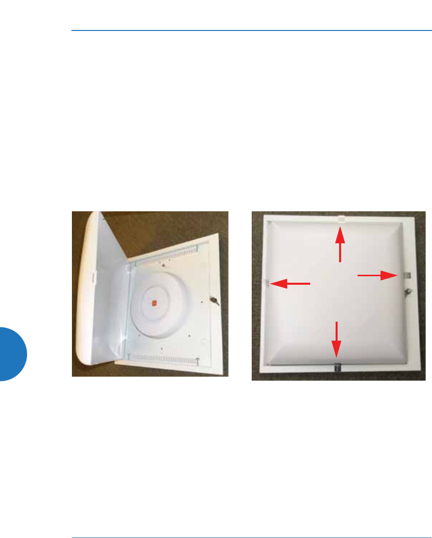
Wireless Access Point
592
IMPORTANT:
z
Before you apply the tamper-evident seal, clean the area of any grease,
dirt, or oil. We recommend using alcohol-based cleaning pads for this.
z
Each seal must be applied to straddle both sides of an opening or seam so
that it will show if an attempt has been made to open or tamper with the
AP or enclosure.
Applying Tamper Evident Seals
This section describes applying seals for indoor APs. For outdoor deployments,
special outdoor AP models for FIPS must be ordered—these are modified at the
factory for FIPS Level 2 compliance.
Figure 230. Tamper Evident Seal Application for Indoor Enclosure
1. For Indoor APs: Install the AP in a properly mounted locking Indoor
Enclosure, per the instructions in its Quick Install Guide. Verify that the AP
is operational, then close and lock the enclosure.
Place 4 tamper evident seals
as shown
Indoor Enclosure, showing AP
installed
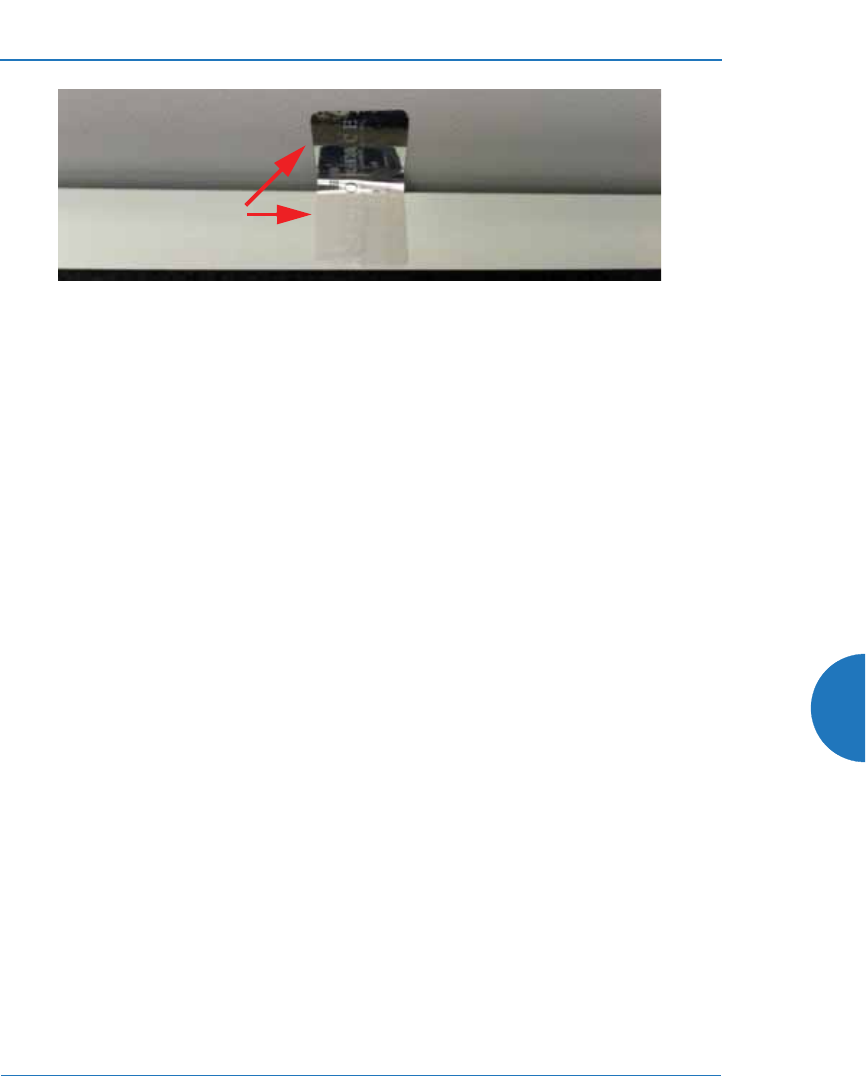
Wireless Access Point
593
Figure 231. Tamper Evident Seal Application Close-up
2. Apply four seals, near the middle of each of the sides of the enclosure and
straddling the slight gap between the metal back and the plastic dome
cover as shown below. IMPORTANT: Make sure that each seal straddles
a seam.
To implement FIPS 140-2, Level 2 using WMI
You must enable FIPS 140-2, Level 2 Security on the AP by turning on the FIPS
setting. For details of the configuration changes that are enforced by that
command, see “About FIPS Configuration” on page 597.
To enable FIPS using the Web Management Interface (WMI), follow the steps
below after the AP has Internet connectivity. (To do this using the CLI, please see
“To implement FIPS 140-2, Level 2 using CLI:” on page 596.)
1. Open a web browser and enter the hostname of the AP. By default, this is
its serial number, which may be found on the back of the AP and on the
label of the box that it came in. For example, enter the URL https://
XR4012807707A. Log in—the default user name/password is admin/
admin. If you have any difficulties, please see “AP Management
Interfaces” on page 76.
#The following steps must be performed in the order shown — you must
enable FIPS 140-2 before you create SSIDs. Otherwise, FIPS mode will
change the PSK keys of SSIDs, and you will not know what the keys are.
Each seal straddles
both sides of an
opening
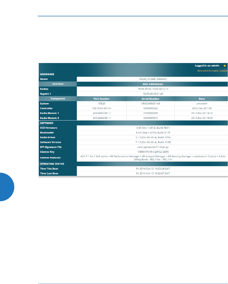
Wireless Access Point
594
2. First verify that the software release running on the unit has been
certified for FIPS (see the Note on page 591). Click Status > Access Point
in the menu on the left of the WMI window. Then click Information. In
the Software Configuration section, check the System Software Version.
(Figure 232) If you have the desired software version, skip to Step 4.
Figure 232. AP Information
3. If you need to run a different software release, first log in to your account
at support.xirrus.com. Download the desired FIPS-certified software
image (see the Note on page 591). Click Tools > System Tools in the
menu on the left of the WMI window. Follow the directions in Step —
System Upgrade under “System” on page 414.
4. Click Configuration > Security in the menu on the left of the WMI
window. Then click Management Control. In the Management Modes
section, set FIPS 140-2, Level 2 Security to On. (Figure 233) The AP will
change the required settings, then reboot.
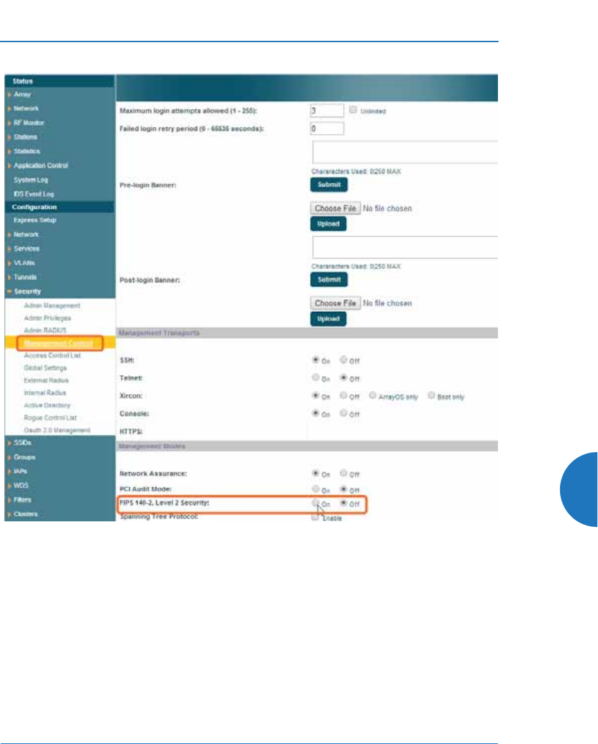
Wireless Access Point
595
Figure 233. Security - Management Control Window
5. You may now proceed to define SSIDs, as described in “SSIDs” on
page 227.

Wireless Access Point
596
To implement FIPS 140-2, Level 2 using CLI:
For details of the settings that are enforced for FIPS Level 2, see “About FIPS
Configuration” on page 597.
1. Use the following command to check that the System Software version
running on the unit is one that has been certified for FIPS (see the Note on
page 591).
AP# show system-info
If necessary, upgrade the AP to a certified release. (See Step 3 in the
previous procedure.)
2. The following CLI commands will perform all of the settings required to
put the AP in FIPS mode.
AP# config
AP(config}# management
AP(config-mgmt}# fips on
3. You may now proceed to define SSIDs, as described in “SSIDs” on
page 227.
4. Use the fips off command if you wish to stop enforcing FIPS security
requirements on the AP.
AP(config-mgmt}# fips off
To check if AP is in FIPS mode:
You may determine whether or not the AP is running in FIPS mode.
z
In the WMI, open the Security > Management Control page and view the
FIPS 140-2, Level 2 Security setting.
#The following steps must be performed in the order shown — you must
enable FIPS 140-2 before you create SSIDs. Otherwise, FIPS mode will
change the PSK keys of SSIDs, and you will not know what the keys are.

Wireless Access Point
597
z
In the CLI, enter show management and check the FIPS 140-2 Mode
setting.
See Also
The Web Management Interface
The Command Line Interface
About FIPS Configuration
When you put the AP in FIPS mode, it checks that the following settings are in
effect, and changes them as needed.
1. Telnet is disabled. See “Management Control” on page 238.
2. SSH is enabled. See “Management Control” on page 238.
3. SNMP (v1/v2/v3) is disabled. See “SNMP” on page 197.
4. Xircon is disabled. See “Management Control” on page 238.
5. XMS-Cloud management is disabled. See “management” on page 475.
6. Management over IAP is disabled. See “Global Settings” on page 319.
7. Fast roaming is disabled. See “Global Settings” on page 319.
8. RADIUS administrator authentication is disabled. See “Admin RADIUS”
on page 235.
9. Global security settings: AES is enabled, TKIP is disabled, PSK is enabled,
EAP is disabled, WPA Pre-Shared Key is set to the FIPS default hex value:
0123456789abcdef0123456789abcdef0123456789abcdef0123456789abcdef
See “Global Settings” on page 250.
10. SSID security settings: Encryption is set to WPA2, AES is enabled, TKIP is
disabled, PSK is enabled, EAP is disabled, WPA Pre-Shared Key is set to
the FIPS default hex value:
0123456789abcdef0123456789abcdef0123456789abcdef0123456789abcdef
See “SSID Management” on page 277.

Wireless Access Point
598
11. These additional features are not allowed in FIPS mode: FTP, TFTP, and
zero-touch activation. Only FIPS approved ciphers are used for SSH/
HTTPS in FIPS mode.
12. When FIPS mode is enabled/disabled, CSPs (critical security parameters)
are zeroed, configuration is saved and the system is rebooted.

Wireless Access Point
Glossary of Terms 599
Glossary of Terms
802.11a
A supplement to the IEEE 802.11 WLAN specification that describes radio
transmissions at a frequency of 5 GHz and data rates of up to 54 Mbps.
802.11ac
A supplement to the IEEE 802.11 WLAN specification. Operates in the 5 GHz
range, using a number of advanced techniques to achieve a maximum speed of
1.3 Gbps. These techniques include improvements on the methods used for
802.11n, below.
802.11b
A supplement to the IEEE 802.11 WLAN specification that describes radio
transmissions at a frequency of 2.4 GHz and data rates of up to 11 Mbps.
802.11d
A supplement to the Media Access Control (MAC) layer in 802.11 to promote
worldwide use of 802.11 WLANs. It allows Access Points to communicate
information on the permissible radio channels with acceptable power levels for
user devices. Because the 802.11 standards cannot legally operate in some
countries, 802.11d adds features and restrictions to allow WLANs to operate
within the rules of these countries.
802.11g
A supplement to the IEEE 802.11 WLAN specification that describes radio
transmissions at a frequency of 2.4 GHz and data rates of up to 54 Mbps.
802.11n
A supplement to the IEEE 802.11 WLAN specification that describes
enhancements to 802.11a/b/g to greatly enhance reach, speed, and capacity.
802.1Q
An IEEE standard for MAC layer frame tagging (also known as encapsulation).
Frame tagging uniquely assigns a user-defined ID to each frame. It also enables a
switch to communicate VLAN membership information across multiple (and
multi-vendor) devices by frame tagging.

Wireless Access Point
600 Glossary of Terms
AES
(Advanced Encryption Standard) A data encryption scheme that uses three
different key sizes (128-bit, 192-bit, and 256-bit). AES was adopted by the U.S.
government in 2002 as the encryption standard for protecting sensitive but
unclassified electronic data.
authentication
The process that a station, device, or user employs to announce its identify to
the network which validates it. IEEE 802.11 specifies two forms of authentication,
open system and shared key.
bandwidth
Specifies the amount of the frequency spectrum that is usable for data transfer. In
other words, it identifies the maximum data rate a signal can attain on
the medium without encountering significant attenuation (loss of power).
beacon interval
When a device in a wireless network sends a beacon, it includes with it a beacon
interval, which specifies the period of time before it will send the beacon again.
The interval tells receiving devices on the network how long they can wait in low
power mode before waking up to handle the beacon. Network administrators can
adjust the beacon interval — usually measured in milliseconds (ms) or its
equivalent, kilo-microseconds (Kmsec).
bit rate
The transmission rate of binary symbols ('0' and '1'), equal to the total number of
bits transmitted in one second.
BSS
(Basic Service Set) When a WLAN is operating in infrastructure mode, each access
point and its connected devices are called the Basic Service Set.
BSSID
The unique identifier for an access point in a BSS network. See also, SSID.

Wireless Access Point
Glossary of Terms 601
CDP
(Cisco Discovery Protocol) CDP is a layer 2 network protocol which runs on most
Cisco equipment and some other network equipment. It is used to share
information with other directly connected network devices. Information such as
the model, network capabilities, and IP address is shared. Wireless APs can both
advertise their presence by sending CDP announcements, and gather and display
information sent by neighbors.
cell
The basic geographical unit of a cellular communications system. Service
coverage of a given area is based on an interlocking network of cells, each with a
radio base station (transmitter/receiver) at its center. The size of each cell is
determined by the terrain and forecasted number of users.
channel
A specific portion of the radio spectrum — the channels allotted to one of
the wireless networking protocols. For example, 802.11ac and 802.11g use 14
channels in the 2.4 GHz band, only 3 of which don't overlap (1, 6, and 11).
CoS
(Class of Service) A category based on the type of user, type of application,
or some other criteria that QoS systems can use to provide differentiated classes of
service.
default gateway
The gateway in a network that a computer will use to access another network if
a gateway is not specified for use. In a network using subnets, a default gateway
is the router that forwards traffic to a destination outside of the subnet of
the transmitting device.
DHCP
(Dynamic Host Configuration Protocol) A method for dynamically assigning IP
addresses to devices on a network. DHCP issues IP addresses automatically
within a specified range to client devices when they are first powered up.
DHCP lease
The DHCP lease is the amount of time that the DHCP server grants to the DHCP
client for permission to use a particular IP address. A typical DHCP server allows
its administrator to set the lease time.

Wireless Access Point
602 Glossary of Terms
DNS
(Domain Name System) A system that maps meaningful domain names with
complex numeric IP addresses. DNS is actually a separate network — if one DNS
server cannot translate a domain name, it will ask a second or third until a server
is found with the correct IP address.
domain
The main name/Internet address of a user's Internet site as registered with
the InterNIC organization, which handles domain registration on the Internet. For
example, the “domain” address for Google is: http://www.google.com, broken
down as follows:
z
http:// represents the Hyper Text Teleprocessing Protocol used by all Web
pages.
z
www is a reference to the World Wide Web.
z
google refers to the company.
z
com specifies that the domain belongs to a commercial enterprise.
DTIM
(Delivery Traffic Indication Message) A DTIM is a signal sent as part of a beacon
by an access point to a client device in sleep mode, alerting the device to a packet
awaiting delivery.
EAP
(Extensible Authentication Protocol) When you log on to the Internet, you're most
likely establishing a PPP connection via a remote access server. The password,
key, or other device you use to prove that you are authorized to do so is controlled
via PPP’s Link Control Protocol (LCP). However, LCP is somewhat inflexible
because it has to specify an authentication device early in the process. EAP allows
the system to gather more information from the user before deciding which
authenticator to use. It is called extensible because it allows more authenticator
types than LCP (for example, passwords and public keys).

Wireless Access Point
Glossary of Terms 603
EDCF
(Enhanced Distributed Coordinator Function) A QoS extension which uses
the same contention-based access mechanism as current devices but adds “offset
contention windows” that separate high priority packets from low priority
packets (by assigning a larger random backoff window to lower priorities than to
higher priorities). The result is “statistical priority,” where high-priority packets
usually are transmitted before low-priority packets.
encapsulation
A way of wrapping protocols such as TCP/IP, AppleTalk, and NetBEUI in
Ethernet frames so they can traverse an Ethernet network and be unwrapped
when they reach the destination computer.
encryption
Any procedure used in cryptography to translate data into a form that can be
decrypted and read only by its intended receiver.
Fast Ethernet
A version of standard Ethernet that runs at 100 Mbps rather than 10 Mbps.
FCC
(Federal Communications Commission) US wireless regulatory authority.
The FCC was established by the Communications Act of 1934 and is charged with
regulating Interstate and International communications by radio, television, wire,
satellite and cable.
FIPS
The Federal Information Processing Standard (FIPS) Publication 140-2 establishes
a computer security standard used to accredit cryptographic modules.
The standard is a joint effort by the U.S. and Canadian governments.
frame
A packet encapsulated to travel on a physical medium, like Ethernet or Wi-Fi. If a
packet is like a shipping container, a frame is the boat on which the shipping
container is loaded.

Wireless Access Point
604 Glossary of Terms
Gigabit 1 through 4
The Gigabit Ethernet interfaces on XR Series APs. XR-4000 Series APs have two
gigabit interfaces, while XR-6000 Series and higher models have four gigabit
interfaces. See also, Gigabit Ethernet.
Gigabit Ethernet
A version of Ethernet with data transfer rates of 1 Gigabit (1,000 Mbps).
Group
A user group, created to define a set of attributes (such as VLAN, traffic limits,
and Web Page Redirect) and privileges (such as fast roaming) that apply to all
users that are members of the group. This allows a uniform configuration to be
easily applied to multiple user accounts. The attributes that can be configured for
user groups are almost identical to those that can be configured for SSIDs.
host name
The unique name that identifies a computer on a network. On the Internet,
the host name is in the form comp.xyz.net. If there is only one Internet site
the host name is the same as the domain name. One computer can have more than
one host name if it hosts more than one Internet site (for example, home.xyz.net
and comp.xyz.net). In this case, comp and home are the host names and xyz.net is
the domain name.
IPsec
A Layer 3 authentication and encryption protocol. Used to secure VPNs.
LLDP
The Link Layer Discovery Protocol (LLDP) is a vendor-neutral link layer protocol
used for advertising identities, capabilities, and neighbors on an IEEE 802 local
area network
MAC address
(Media Access Control Address) A 6-byte hexadecimal address assigned by a
manufacturer to a device.
Mbps
(Megabits per second) A standard measure for data transmission speeds (for
example, the rate at which information travels over the Internet). 1 Mbps denotes
one million bits per second.

Wireless Access Point
Glossary of Terms 605
MTU
(Maximum Transmission Unit) The largest physical packet size — measured in
bytes — that a network can transmit. Any messages larger than the MTU are
divided into smaller packets before being sent. Every network has a different
MTU, which is set by the network administrator. Ideally, you want the MTU to be
the same as the smallest MTU of all the networks between your machine and
a message's final destination. Otherwise, if your messages are larger than one of
the intervening MTUs, they will get broken up (fragmented), which slows down
transmission speeds.
NTP
(Network Time Protocol) An Internet standard protocol (built on top of TCP/IP)
that ensures the accurate synchronization (to the millisecond) of computer clock
times in a network of computers. Running as a continuous background client
program on a computer, NTP sends periodic time requests to servers, obtaining
server time stamps and using them to adjust the client's clock.
packet
Data sent over a network is broken down into many small pieces — packets — by
the Transmission Control Protocol layer of TCP/IP. Each packet contains the
address of its destination as well the data. Packets may be sent on any number of
routes to their destination, where they are reassembled into the original data. This
system is optimal for connectionless networks, such as the Internet, where there
are no fixed connections between two locations.
PLCP
(Physical Layer Convergence Protocol) Defined by IEEE 802.6, a protocol
specified within the Transmission Convergence layer that defines exactly how
cells are formatted within a data stream for a particular type of transmission
facility.
POE
This refers to the optional Xirrus-supplied Power over Gigabit Ethernet modules
that provide DC power to APs. Power is supplied over the same Cat 5e or Cat 6
cable that supplies the data connection to your gigabit Ethernet switch, thus
eliminating the need to run a power cable.

Wireless Access Point
606 Glossary of Terms
preamble
Preamble (sometimes called a header) is a section of data at the head of a packet
that contains information that the access point and client devices need when
sending and receiving packets. PLCP Has two structures, a long and a short
preamble. All compliant 802.11b systems have to support the long preamble.
The short preamble option is provided in the standard to improve the efficiency
of a network's throughput when transmitting special data, such as voice, VoIP
(Voice-over IP) and streaming video.
private key
In cryptography, one of a pair of keys (one public and one private) that are created
with the same algorithm for encrypting and decrypting messages and digital
signatures. The private key is provided only to the requestor and never shared.
The requestor uses the private key to decrypt text that has been encrypted with
the public key by someone else.
PSK
(Pre-Shared Key) A TKIP passphrase used to protect your network traffic in WPA.
public key
In cryptography, one of a pair of keys (one public and one private) that are created
with the same algorithm for encrypting and decrypting messages and digital
signatures. The public key is made publicly available for encryption and
decryption.
QoS
(Quality of Service) QoS can be used to describe any number of ways in which
a network provider prioritizes or guarantees a service's performance.
RADIUS
(Remote Authentication Dial-In User Service) A client-server security protocol,
developed to authenticate, authorize, and account for dial-up users. The RADIUS
server stores user profiles, which include passwords and authorization attributes.
RSSI
(Received Signal Strength Indicator) A measure of the energy observed by an
antenna when receiving a signal.

Wireless Access Point
Glossary of Terms 607
SDMA
(Spatial Division Multiple Access) A wireless communications mode that
optimizes the use of the radio spectrum and minimizes cost by taking advantage
of the directional properties of antennas. The antennas are highly directional,
allowing duplicate frequencies to be used for multiple zones.
SNMP
(Simple Network Management Protocol) A standard protocol that regulates
network management over the Internet.
SNTP
(Simple Network Time Protocol) A simplified version of NTP. SNTP can be used
when the ultimate performance of the full NTP implementation described in RFC
1305 is not needed or justified.
SSH
(Secure SHell) Developed by SSH Communications Security, Secure Shell is a
program to log into another computer over a network, to execute commands in a
remote machine, and to move files from one machine to another. The AP only
allows SSH-2 connections. SSH-2 provides strong authentication and secure
communications over insecure channels. SSH-2 protects a network from attacks,
such as IP spoofing, IP source routing, and DNS spoofing. Attackers who has
managed to take over a network can only force SSH to disconnect — they cannot
“play back” the traffic or hijack the connection when encryption is enabled. When
using SSH-2's slogin (instead of rlogin) the entire login session, including
transmission of password, is encrypted making it almost impossible for an
outsider to collect passwords. Be aware that your SSH utility must be set up to use
SSH-2.
SSID
(Service Set IDentifier) Every wireless network or network subset (such as a BSS)
has a unique identifier called an SSID. Every device connected to that part of the
network uses the same SSID to identify itself as part of the family — when it wants
to gain access to the network or verify the origin of a data packet it is sending over
the network. In short, it is the unique name shared among all devices in a WLAN.

Wireless Access Point
608 Glossary of Terms
subnet mask
A mask used to determine what subnet an IP address belongs to. An IP address
has two components: (1) the network address and (2) the host address. For
example, consider the IP address 150.215.017.009. Assuming this is part of a Class
B network, the first two numbers (150.215) represent the Class B network address,
and the second two numbers (017.009) identify a particular host on this network.
TKIP
(Temporal Key Integrity Protocol) Provides improved data encryption by
scrambling the keys using a hashing algorithm and, by adding an integrity-
checking feature, ensures that the encryption keys haven’t been tampered with.
transmit power
The amount of power used by a radio transceiver to send the signal out. Transmit
power is generally measured in milliwatts, which you can convert to dBm.
User group
See Group.
VLAN
(Virtual LAN) A group of devices that communicate as a single network, even
though they are physically located on different LAN segments. Because VLANs
are based on logical rather than physical connections, they are extremely flexible.
A device that is moved to another location can remain on the same VLAN
without any hardware reconfiguration.
VLAN tagging
(Virtual LAN tagging) Static port-based VLANs were originally the only way to
segment a network without using routing, but these port-based VLANs could
only be implemented on a single switch (or switches) cabled together. Routing
was required to transfer traffic between unconnected switches. As an alternative
to routing, some vendors created proprietary schemes for sharing VLAN
information across switches. These methods would only operate on that vendor's
equipment and were not an acceptable way to implement VLANs. With the
adoption of the 802.11n standard, traffic can be confined to VLANs that exist on

Wireless Access Point
Glossary of Terms 609
multiple switches from different vendors. This interoperability and traffic
containment across different switches is the result of a switch's ability to use and
recognize 802.1Q tag headers — called VLAN tagging. Switches that implement
802.1Q tagging add this tag header to the frame directly after the destination and
source MAC addresses. The tag header indicates:
1. That the packet has a tag.
2. Whether the packet should have priority over other packets.
3. Which VLAN it belongs to, so that the switch can forward or filter it
correctly.
WDS (Wireless Distribution System)
WDS creates wireless backhauls between APs. These links between APs may be
used rather than having to install data cabling to each AP.
WEP
(Wired Equivalent Privacy) An optional IEEE 802.11 function that offers frame
transmission privacy similar to a wired network. The Wired Equivalent Privacy
generates secret shared encryption keys that both source and destination stations
can use to alter frame bits to avoid disclosure to eavesdroppers.
Wi-Fi Alliance
A nonprofit international association formed in 1999 to certify interoperability of
wireless Local Area Network products based on IEEE 802.11 specification. The
goal of the Wi-Fi Alliance's members is to enhance the user experience through
product interoperability.
Wireless AP
A high capacity wireless networking device consisting of multiple radios
arranged in a circular AP.
WPA
(Wi-Fi Protected Access) A Wi-Fi Alliance standard that contains a subset of the
IEEE 802.11i standard, using TKIP as an encryption method and 802.1x for
authentication.

Wireless Access Point
610 Glossary of Terms
WPA2
(Wi-Fi Protected Access 2) WPA2 is the follow-on security method to WPA for
wireless networks and provides stronger data protection and network access
control. It offers Enterprise and consumer Wi-Fi users with a high level of
assurance that only authorized users can access their wireless networks. Like
WPA, WPA2 is designed to secure all versions of 802.11 devices, including
802.11a, 802.11b, 802.11g, and 802.11n, multi-band and multi-mode.
Xirrus Management System (XMS)
A Xirrus product used for managing large Wireless AP deployments from a
centralized Web-based interface.
Xirrus Release 7.6 1/11/16

Wireless Access Point
Index 611
Index
Numerics
11ac
see 802.11ac 350
802.11a 3, 4, 313, 335
802.11a/b/g 32
802.11a/b/g/n 18
802.11a/n 18, 72, 277
802.11ac
WMI page 350
802.11b 3, 4, 341
802.11b/g 313, 341
802.11b/g/n 18, 72, 277
802.11e 21
802.11g 3, 4, 341
802.11i 4, 80, 163
802.11n 4
WMI page 347
802.11p 21
802.11q 21
802.1x 4, 56, 66, 80, 163, 524
A
abg(n)
nomenclature 2
abg(n)2
intrusion detection 377
self-monitoring
radio assurance (loopback
mode) 359, 360
Access Control List 225, 524
access control lists (ACLs) 248, 299
Access Point 163
Access Points, XR
overview 4
access points, XR 1
account, user 260
ACLs 56, 225, 524
active directory 260
active IAPs
per SSID 298
active software image 415
Address Resolution Protocol
window 110
Address Resolution Protocol (ARP)
332
Admin 524
Admin ID 231
authentication via RADIUS 235
Admin Management 231
admin privileges
setting in admin RADIUS account
235
admin RADIUS account
if using Console port 235
admin RADIUS authentication 235
administration 80, 163, 225
Administrator Account 518
Advanced Encryption Standard 56,
524
Advanced RF Analysis Manager
see RAM 23
Advanced RF Performance Manager
see RPM 21
Advanced RF Security Manager
see RSM 22
AeroScout
see WiFi tag 190
AES 4, 20, 56, 66, 80, 163, 516, 524
AirWatch 406
Airwatch
CLI command 477
allow traffic
see filters 391
Analysis Manager
see RAM 23
appearance

Wireless Access Point
612 Index
WMI options 433
application control
custom list 392, 394
update (signature file) 422
approved
setting rogues 120
APs 66, 120, 264, 265, 524
rogues, blocking 376
APs, rogue
see rogue APs 358, 377
APs, XR
overview 4
ARP filtering 332
ARP table window 110
Array 34, 72, 86, 163, 170
connecting 72
dismounting 72
management 411
mounting 72
powering up 72
securing 72
Web Management Interface 86
XR-2000 Series 9, 10, 11
XR-2005 Series 9, 10, 11
ArrayOS
upgrade 414
Arrays
managing in clusters 401
Arrays, XR 1
overview 4
associated users 34
assurance
network server connectivity 113,
243
assurance (radio loopback testing) 358
assurance, station
see station assurance 365
attack (DoS)
see DoS attack 379
attack (impersonation)
see impersonation attack 379
auth CLI command 454
authentication 20, 260
of admin via RADIUS 235
authentication (Oauth token)
CLI command
auth 454
authority
certificate 229, 245
auto block
rogue APs, settings 377
Auto Cell
by band for 5G 338, 343
by channel for 5G 338, 343
monitor mode 338, 344
auto negotiate 170
auto-blocking
rogue APs 376
auto-configuration 80, 319, 335, 341
channel and cell size 358
automatic refresh
setting interval 433
automatic update from remote server
configuration files, boot image 416
B
backhaul
see WDS 63
backup unit
see standby mode 358
band association 277
beacon interval 319
Beacon World Mode 319
beam distribution 18
benefits 18
block
rogue APs, settings 374
block (rogue APs)
see auto block 377
blocking

Wireless Access Point
Index 613
rogue APs 376
blocking rogue APs 358
bond
mode, bridging 173
boot 415
bridging APs 173
broadcast 333
fast roaming 333
browser
certificate error 229, 245
BSS 522
BSSID 120, 522
buttons 91
BYOD (Bring Your Own Device) 281
C
capacity
of 802.11n 50
cascading style sheet
sample for web page redirect 424
CDP 454
CDP (Cisco Discovery Protocol)
settings 181
cdp CLI command 454
CDP neighbors 112
cell
sharp cell 358
cell size 34, 313
auto-configuration 358
cell size configuration 358
certificate
about 229, 245
authority 229, 245
error 229, 245
install Xirrus authority 245
X.509 229, 245
chain
see bridging 173
channel
auto-configuration 358
configuration 358
list selection 358
channels 34, 120, 313, 319, 335, 341
non-overlapping 20
CHAP (Challenge-Handshake Au-
thentication Protocol)
Admin RADIUS settings 236
web page redirect 289
CHAP Challenge Handshake Authen-
tication Protocol)
RADIUS ping 425
character restrictions 93
Chrome 30
Cisco Discovery Protocol
see cdp 454
Cisco Discovery Protocol (CDP) 181
CLI 4, 66, 69, 75, 76, 435
executing from WMI 426
vs. XMS 85
CLI commands
see commands 454
client
web page redirect 423
Cloud
Personal Wi-Fi 290, 302
WPR 290
cluster
CLI command 458
clusters 401
management 401
command
wifi-tag 495
Command Line Interface 4, 62, 69, 72,
75, 76, 435, 524
configuration commands 452
getting help 437
getting started 437
inputting commands 437
sample configuration tasks 497
SSH 435

Wireless Access Point
614 Index
top level commands 440
command, utilities
ping, traceroute, RADIUS ping 424
commands
acl 452
admin 453
auth, authentication 454
cdp 454
clear 456
cluster 458
configure 441
contact-info 459
date-time 460
dhcp-server 461
dns 462
file 463
filter 467
group 458, 471
hostname 471
interface 472
load 473
location 473
location-reporting 474, 486
management 475
mdm (mobile device management)
Airwatch 477
more 478
netflow 479
no 480
quit 482
radius-server 481, 482
reboot 484, 494
reset 484
restore 485
run-tests 487
security 489
show 445
snmp 490
ssid 491
statistics 450
syslog 492
tunnel 493
vlan 494
Community String 515
compass heading 100
configuration 161, 524
express setup 163
reset to factory defaults 420
configuration changes
applying 93
configuration files
automatic update from remote
server 416
download 417
update from local file 417
update from remote file 417
connection
tracking window 111
connectivity
servers, see network assurance
113, 243
Console port
login via 235
coverage 34, 69
extended 18
coverage patterns 4
critical messages 89
CTS/RTS 335, 341
custom application control list 392, 394
D
daisy chain
see bridging 173
data rate 335, 341
date/time restrictions
and interactions 309
default gateway 80, 170
default settings 513
Default Value 516
DHCP 515

Wireless Access Point
Index 615
defaults
reset configuration to factory de-
faults 420
Delivery Traffic Indication Message
319
denial of service
see DoS attack 379
deny traffic
see filters 391
deployment 32, 62, 66, 69, 524
detection
intrusion 377
see DoS attack 379
see impersonation attack 379
see impersonation detection 379
see intrusion detection 379
device management
see Mobile Device Management
406
DHCP 34, 75, 76, 80, 163, 170, 514
default settings 515
leases window 111
DHCP Server 185
diagnostics
log, create file 421
directory, active 260
Discovery Protocol
Cisco (CDP) 181
Link Layer 182
display
WMI options 433
DNS 80, 163, 180
DNS domain 180
DNS server 180
Domain Name System 180
DoS attack detection
settings 379
DTIM 319
DTIM period 319
duplex 170
dynamic VLAN
overridden by group 307
E
EAP 516, 524
EAP-MDS 20
EAP-PEAP 524
EAP-TLS 20, 56, 524
EAP-TTLS 20, 56, 524
EasyPass Onboarding
User-PSK 281
EDCF 319
Encryption 516, 524
encryption 20
encryption method
recommended (WPA2 with AES)
227
setting 228
support of multiple methods 227
encryption method (encryption mode)
Open, WEP, WPA, WPA2, WPA-
Both 227
encryption standard
AES, TKIP, both 227
setting 228
Enterprise 1, 3, 524
WLAN 3
Enterprise Class Management 4
Enterprise Class Security 4
ESS 522
ESSID 522
Ethernet 69, 72, 75, 76, 80, 163
Euclid
location service
data format 533
event log
IDS (intrusion detection) 158
see system log 150
event messages 89
Express Setup 72, 80, 163

Wireless Access Point
616 Index
express setup 80, 163
Extended Service Set 522
Extensible Authentication Protocol 524
F
factory default settings 513
factory defaults 514, 515, 516, 518
DHCP 515
reset configuration to 417
factory.conf 417
fail-over
standby mode 358
failover 52, 66
FAQs 522
Fast Ethernet 69, 75, 76, 163, 170, 513
fast roaming 20, 107, 333
about 312
and VLANs 312
features 18, 62, 170, 189, 193, 319, 524
and license key 80, 414
Federal Information Processing Stan-
dard (FIPS)
see FIPS 591
feedback 91
filter list 392
filter name 395
filtering
IPv6 333
filters 391, 392, 395
custom application control list 392,
394
stateful filtering, disabling 393
statistics 147
FIPS 244
FIPS 140-2 Security 591
Firefox 30
firewall 391
and port usage 58
stateful filtering, disabling 393
fragmentation threshold 335, 341
frequently asked questions 522
FTP 524
G
General Hints 521
getting started
express setup 163
Gigabit 69, 75, 76, 80, 163, 170, 513
global settings 319, 335, 341
glossary of terms 599
Google Chrome 30
Group
management 306
group 304
CLI command 458, 471
VLAN overrides dynamic VLAN
307
group limits and interactions 309
Group Rekey 516
Guest Access
WPR 290
GUI
see WMI 433
H
heading, compass 100
help 91
button, bottom of page 91
button, left frame 89
Help button 86
honeypot 300
honeypot SSID
whitelist settings 301
host name 80, 86, 163, 180
hs.css 424
HTTPS
certificate, see certificate 245
HTTPS port
web page redirect 287, 297
HyperTerminal 30, 69

Wireless Access Point
Index 617
I
IAP 34, 72, 163, 313
active SSIDs 298
naming 2
see also radio 311
settings 313
IAP LED 72
IDS
see Intrusion Detection 373
IDS event log
viewing window 158
IEEE 3, 80, 163
IEEE 802.11ac
WMI page 350
IEEE 802.11n
capacity, increased 50
multiple data streams 44
spatial multiplexing 44
WMI page 347
IEEE 802.1Q 527
image
active software image 415
upgrade software image 414
impersonation attack detection
settings 379
implementing Voice over Wi-Fi 271
installation 29, 67, 72
installing the MCAP-3616 69
mounting the unit 72
requirements 29
workflow 67
installation workflow 67
interfaces 163
Web 85
internal login page
web page redirect 287
web page redirect, customize 292
internal splash page
web page redirect 288
web page redirect, customize 292
Internet Explorer 30
interval
automatic WMI refresh 433
intrusion detection 120, 377
and auto block settings 377
configuration 358
setting as approved or known 120
intrusion detection (IDS)
viewing event log 158
Intrusion Detection (IDS/IPS) 373
IP Address 34, 80, 86, 92, 120, 163, 170,
180, 193, 197, 411, 514
IP Subnet Mask 80
IPS
see Intrusion Detection 373
IPv6
filtering 333
K
key
upgrade 80, 414
key features 18
Keyboard Shortcuts 519
keyboard shortcuts 519
known
setting rogues 120
L
lastboot.conf 417
Layer 3
fast roaming 312
LDAP 260
lease 514
Lease Time 514
leases, DHCP
viewing 111
LEDs 72
sequence 72
settings 380
license Key

Wireless Access Point
618 Index
upgrading 80, 414
limits
group 309
interactions 309
station 309
traffic 309
Link Layer Discovery Protocol (LLDP)
182
list
custom application control list 392,
394
list, access control
see access control list 248, 299
list, MAC access
see access control list 248
list, SSID access
see access control list 299
LLDP (Link Layer Discovery Protocol)
settings 182
LLDP List 113
local management vs. XMS 85
location
CLI command
location-reporting 474, 486
location information 80, 86, 163
location service
data formats 533
log
diagnostics, create file 421
log messages
counters 90
log, IDS(intrusion detection)
viewing window 158
log, system (event)
viewing window 150
logging in 75, 76, 92
Login 92
login
via Console port 235
login page
web page redirect 287, 423
web page redirect, customize 292
logout 434
long retry limit 319
loopback
see radio assurance 509
loopback testing
radio assurance mode 358
M
MAC 56, 75, 76, 522, 524
MAC Access Control Lists 56
MAC Access List 248
MAC address 248, 522, 524
Management 518, 524
management 95, 161, 411
Array clusters 401
local vs. XMS 85
of Arrays 411
Web Management Interface (WMI)
85
management (XMS) 20
maximum lease 514
Maximum Lease Time 514
MDM
see Mobile Device Management
406
Megabit 80
Message Integrity Check 524
messages
syslog counters 90
MIC 20, 524
Mobile Device Management
AirWatch 406
mobile device management
Airwatch (CLI command) 477
Mobile Device Management (MDM)
406
monitor
mode for Auto Cell 338, 344

Wireless Access Point
Index 619
monitoring
intrusion detection 120
see intrusion detection 377
mounting 72
mounting plate 72
mounting the unit 72
MTU 170
size 170
multiple data streams 44
N
NAT
table - see connection tracking 111
neighbors, CDP 112
neighbors, LLDP 113
Netflow 189
netflow
CLI command 479
network
interfaces 169
settings 170
network assurance 113, 243
network connections 69, 92, 524
network installation 29
network interface ports 75, 76
network interfaces 170, 513
network status
ARP table window 110
connection
tracking window 111
routing table window 110
viewing leases 111
Network Time Protocol 80, 163, 186
network tools
ping, traceroute, RADIUS ping 424
nomenclature 2
non-overlapping channels 20
north
see compass heading 100
NTP 80, 163, 186, 514
NTP Server 186
O
Oauth
CLI command
auth 454
Onboarding
EasyPass, User-PSK 281
Open (encryption method) 227
optimization, VLAN 333
options
WMI 433
orientation
see compass heading 100
overview 4
P
PAP (Password Authentication Proto-
col)
Admin RADIUS settings 236
RADIUS ping 425
web page redirect 289
passphrase 56, 80, 163
Password 518, 524
password 92
Payment Card Industry Data Security
Standard
see PCI DSS 585
PCI audit 243
PCI DSS 585
PEAP 20, 387
performance 18
Performance Manager
see RPM 21
Personal Wi-Fi 302
WPR 290
Ping 411
ping 424
planning 52, 55, 56, 62
failover 52

Wireless Access Point
620 Index
network management 62
port failover 52
power 55
security 56
switch failover 52
WDS 63
PoGE 29
PoGE Power Injectors 1
port failover 52
port requirements 58
power
request power (LLDP) 183
power outlet 29
Power over Gigabit Ethernet 2, 29, 55,
69
power planning 55
pre-shared key 56, 66, 524
Print button 86
probe
see Netflow 189
product installation 29
product overview 4
product specifications 27
PSK 66, 516
User-PSK, EasyPass Onboarding
281
PuTTY 29, 62, 80, 163, 524
PuTTy 30
Q
QoS 21, 277, 516, 522, 606
conflicting values 274
levels defined 279, 307
priority 277
SSID 270, 279
about setting QoS 522, 523
default QoS 516
user group 307
quality
of user experience 365
Quality of Service 21
see QoS 279, 307
quick reference guide 513
quick start
express setup 163
R
radio 80, 163, 335, 341, 380
assurance (self-test) 359, 360
fast roaming 312
Intrusion Detection (IDS/IPS) 373
radio assurance (loopback testing) 358
radio assurance (loopback) mode 359,
360
radio distribution 18
radio LED 380
radio LED settings 380
radios
auto block rogues 377
intrusion detection 377
naming 2
RADIUS 4, 29, 56, 66, 225, 248, 299,
514, 524
admin authentication 235
setting admin privileges 235
setting user VSAs 255
Vendor Specific Attributes (VSAs)
532
RADIUS ping
CHAP Challenge Handshake Au-
thentication Protocol) 425
PAP (Password Authentication
Protocol) 425
RADIUS Ping command 425
RADIUS Server 514
RADIUS settings
web page redirect 289
RAM (RF Analysis Manager) 23
reauthentication 319
reboot 415

Wireless Access Point
Index 621
active software image 415
redirect (WPR) 423
refresh interval
WMI 433
remote boot image
automatic update from remote
TFTP server 416
remote configuration
automatic update from remote
server 416
remote TFTP server
automatic update of boot image,
configuration 416
rename
SSID 285
request power (LLDP)
LLDP
request power 183
Reset 411, 514
reset configuration
to factory defaults 420
restore command 485
restrictions
date/time 309
stations 309
traffic 309
RF
intrusion detection 358
spectrum management 358
RF Analysis Manager
see RAM 23
RF configuration 358
RF management
see channel 358
RF monitor mode
for Auto Cell 338, 344
RF Performance Manager
see RPM 21
RF resilience 358
RF Security Manager
see RSM 22
roaming 20, 107, 333
see fast roaming 312
Rogue AP 4, 62, 120, 264, 265, 524
rogue AP
blocking 376
settings for blocking 374
Rogue AP List 120
rogue APs
auto block settings 377
blocking 358
Rogue Control List 264, 265
rogue detection 18
rogues
setting as known or approved 120
root command prompt 440
route
trace route utility 424
routing table window 110
RPM (RF Performance Manager) 21
RSM (RF Security Manager) 22
RSSI 120
RTS 335, 341
RTS threshold 335, 341
S
Safari 30
sample Perl and CSS files for 423
save
with reboot 415
Save button 86
saved.conf 417
scalability 3
schedule
auto channel configuration 358
scheduling
SSID 285
Secondary Port 514
Secondary Server 514
secret 514

Wireless Access Point
622 Index
Secure Shell 30
secure Shell 29
Security
FIPS 591
PCI DSS 585
security 4, 20, 225, 522, 524
certificate, see certificate 245
Security Manager
see RSM 22
see group 304
self-monitoring 377
radio assurance 509
radio assurance options 359, 360
self-test
radio assurance mode 359, 360
serial port 30, 75, 76, 524
server, VTun
see VTun 219
servers
connectivity, see network assur-
ance 113, 243
Service Set Identifier 80
Services 185, 522
settings 163
setup, express 163
sharp cell 358
setting in WMI 362
short retry limit 319
signal processing
MIMO 44
signature file
update (application control) 422
SNMP 4, 16, 80, 163, 170, 185, 197, 515
required for XMS 198
software
upgrade license key 80, 414
software image
active software image 415
Software Upgrade 411
software upgrade 414
spatial multiplexing 44
specifications 27
spectrum (RF) management 358
speed 3, 75, 76, 170
11 Mbps 3
54 Mbps 3
splash page
web page redirect 288, 423
web page redirect, customize 292
SSH 29, 30, 62, 80, 163, 170, 226, 518,
524
SSH-2 226
SSID 4, 80, 86, 120, 163, 265, 277, 516,
522, 527
about usage 522
active IAPs 298
honeypot 300
honeypot, whitelist 301
QoS 270, 279
about using 522, 523
QoS, about usage 522
rename 285
rogue control list 264
scheduling 285
web page redirect settings 283
web page redirect settings, about
287, 297
web page redirect settings, wh-
itelist 293, 294
whitelist, honeypot 300
SSID Access List 299
SSID address 299
SSID Management 277, 516, 522
standby mode 358
stateful filtering
disabling 393
static IP 80, 163, 170
station
assurance 365
station assurance 365

Wireless Access Point
Index 623
station timeout period 319
Stations 522
stations
limits and interactions 309
rogues 120
statistics 147
statistics per station 149
statistics 163
filters 147
netflow 189
per-station 149
stations 147
WDS 144
status bar 86
submitting comments 91
subnet 29, 52, 80, 170
switch failover 52
synchronize 80, 163, 186
Syslog 80, 86, 163, 185, 193, 514
time-stamping 80
syslog messages
counters 90
Syslog reporting 193
Syslog Server 193
system commands
ping, trace route, RADIUS ping
424
System Configuration Reset 411
System Log 193
system log
viewing window 150
System Reboot 411
System Tools 411
system tools 412
T
tag, WiFi 190
TCP
port requirements 58
technical support
frequently asked questions 522
Telnet 226, 518, 524
Temporal Key Integrity Protocol 524
TFTP server
automatic update of boot image,
configuration 416
Time Out 514
time zone 80, 163, 186
timeout 319, 411
Tips 521
TKIP 20, 56, 66, 80, 163, 516, 524
TKIP encryption
and XR Arrays 251
token
CLI command
auth 454
tool
ping, trace route, RADIUS ping
424
Tools 411, 524
tools, network 424
tools, system 412
trace route utility 424
traffic
filtering 391
limits and interactions 309
transmit power 34
Trap Host 515
trap port 197, 515
tunnel
CLI command 493
tunneled
fast roaming 333
Tunnels 220
tunnels
see VTun 214, 219
U
UDP
port requirements 58

Wireless Access Point
624 Index
unknown
setting rogues 120
update
signature file (application control)
422
upgrade
active software image 415
license key 80, 414
software image 414
U-PSK, EasyPass Onboarding 281
user accounts 260
setting RADIUS VSAs 255
user group 304
QoS 307
user group limits and interactions 309
user interface 85
User-PSK, EasyPass Onboarding 281
utilities
ping, trace route, RADIUS ping
424
utility buttons 91
V
Vendor Specific Attributes (VSAs)
RADIUS 532
RADIUS, for Xirrus 532
virtual tunnels
see VTun 219
VLAN 4, 66, 277, 516, 522, 527
broadcast optimization 333
dynamic
overridden by group 307
group (vs. dynamic VLAN) 307
vlan
CLI command 494
VLAN ID 277
VLANs 213
and fast roaming 312
voice
fast roaming 312
implementing on Array 271
Voice-over IP 341
VoIP 341
VoWLAN 21
VPN 80, 163, 524
VTS
Virtual Tunnel Server 214, 219
VTun
specifying tunnel server 214, 219
understanding 214
W
wall thickness considerations 32
warning messages 89
WDS 385, 387
about 63
long distance 317, 387
planning 63
statistics 144
timeouts 317, 387
WDS Client Links 387
Web interface
structure and navigation 89
web interface 85
Web Management Interface 62, 72, 75,
76, 92, 522
Web Management Interface (WMI) 85
web page redirect 423
also called WPR 423
CHAP (Challenge-Handshake Au-
thentication Protocol) 289
customize internal login/splash
page 292
HTTPS port 287, 297
install files for 424
internal login page 287
internal splash page 288
PAP, CHAP 289
RADIUS settings 289
remove files for 424

Wireless Access Point
Index 625
sample WPR files 424
SSID settings 283
SSID settings, about 287, 297
whitelist settings, about 293, 294
WEP 20, 56, 80, 163, 225, 277, 516, 524
WEP (Wired Equivalent Privacy)
encryption method 227
WEP encryption
and XR Arrays 252
whitelist
honeypot 300, 301
web page redirect 293, 294
Wi-Fi
personal 302
Wi-Fi Protected Access 4, 56, 80, 163,
524
WiFi tag 190
wifi-tag
CLI command 495
Wired Equivalent Privacy 80, 524
Wireless Distribution System 385
wireless LAN 3
wireless security 163
WLAN 163
WMI 4, 62, 66, 75, 76, 85, 313
appearance options 433
certificate error 229, 245
executing CLI commands 426
options 433
refresh interval 433
vs. XMS 85
workflow 67
WPA 4, 66, 80, 163, 225, 277, 516, 524
WPA (Wi-Fi Protected Access) and
WPA2
encryption method 227
WPA2 4
WPR
Cloud 290
see web page redirect 423
wpr.pl 423, 424
X
X.509
certificate 229, 245
Xirrus
certificate authority 245
Xirrus Advanced RF Analysis Manag-
er
see RAM 23
Xirrus Advanced RF Performance
Manager
see RPM 21
Xirrus Advanced RF Security Manager
see RSM 22
Xirrus Management System 4, 16, 20,
29, 62, 524
SNMP required 198
Xirrus Management System (XMS) 1
Xirrus PoGE Power Injectors 1
Xirrus Roaming Protocol 20, 107, 333
XMS 4, 16, 20
port requirements 58
setting IP address of 197
SNMP required 198
vs. local management 85
XMS-9000-CL-x 2
XP PoGE Power Injectors 1
XPS 29
XR Array
management 161, 411
XR Arrays 1
overview 4
XR-2000 Series 9, 10, 11
XR-2005 Series 9, 10, 11
XRP 20, 107, 333
xs_current.conf 417

Wireless Access Point
626 Index

1.800.947.7871 Toll Free in the US
+1.805.262.1600 Sales
+1.805.262.1601 Fax
2101 Corporate Center Drive
Thousand Oaks, CA 91320, USA
To learn more visit:
xirrus.com or
email info@xirrus.com
© 201 Xirrus, Inc. All Rights Reserved. The Xirrus logo is a registered trademark of Xirrus, Inc.
All other trademarks are the
p
ro
p
erty of their res
p
ective owners. Content subject to change without notice. 800-0022-001T