Rixson MW700 Series Overhead Concealed Closer Installation Instructions IS MW70012 14
User Manual: Rixson MW700 Series Overhead Concealed Closer Installation Instructions Installation Instructions
Open the PDF directly: View PDF ![]() .
.
Page Count: 2
Installation Instructions
ISMW700 (12-14)
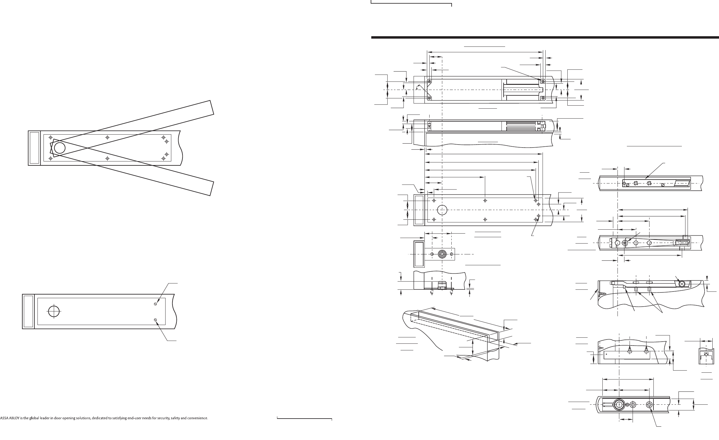
MW700 Series Overhead Concealed Closer (Wood Door & Metal Frame)
MW700 Series, Center Hung Single Acting, Handed
PAGE 4
Rixson 866-474-9766 Technical Department
www.rixson.com
Rixson 866-474-9766 Technical Department
www.rixson.com
7. Adjust closing speed of door.
800 Series
Each valve controls one swing only. To decrease speed
turn clockwise. To increase speed turn counter clockwise.
Adjust each valve screw per illustration.
700 Series
To decrease speed turn valve clockwise. To increase
speed turn valve counter clockwise.
To increase backcheck, turn valve clockwise, to decrease
backcheck turn valve counter clockwise.
6. Centering the door. Open the adjustment valves.
800 Series
Center door in jamb by adjusting centering screws in top
arm. Tighten arm screws securely.
700 Series
Adjust arm centering screws to provide pressure of door
against stop on frame. Tighten main arm screws
securely.
NOTES:
1. Do not scale drawing.
2. #192 Closer Mounting Channel details on
Page 2.
3. Single acting operation requires a door stop
on the underside of frame.
4. #199 door end cap optional extra. (mortise
for top and bottom of door is identical.)
5. Door radius recommended is 2-5/8" (66.7).
6. All dimensions given in inches (mm).
C
L
Jamb Installation
218 Bottom Pivot
3/16 (4.8) Nominal Clearance
Between Bottom of Door
and Finished Floor or
Top Surface of Threshold
Vertically
Adjustable
Pivot
Spindle & Bottom Pivot
1-1/4
(31.8)
4-1/4
(108)
Bottom View
(Cover Plate) 9/32 (7.1) Dia.
Holes for
Adjusting
Valves
(2 Places)
1-3/8
(35)
1-3/8
(35)
Cover Plate
18-1/4 x 3-3/4
(463.6 x 95.3)
31/32
(24.6)
31/32
(24.6)
1-9/16
(39.7)
18-3/4
(476.3)
17-27/32
(453.2)
17-1/2
(444.5)
9-1/2
(241.3)
2-3/4
(69.9) 1-1/2
(38.1)
1/2
(12.7)
#10-24 x 5/16
FHMS Cover
Plate Screws
(6 Places)
1/8
(3.2) Nominal Clearance
1-7/64 (28.2)
From Bottom of
Head Jamb to Top
of Mounting Tabs
Critical Dim.
31/64
(12.3)
1-15/32
(37.3)
1/16
(1.6)
Nominal
Clearance
Max. Height
of Closer
3-23/32
(94.5)
1-23/64
(34.5)
Max. Width
of Closer
9/32 (7.1)
Mounting Holes
17-1/2
(444.5)
2
(50.8)
1/4
(6.4)
Side View
Top View
1/2
(12.7)
1/2
(12.7)
1-3/8
(35)
1-3/8
(35)
1-9/16
(39.7)
45°
1-23/64
(34.5)
1-39/64
(40.9)
1-39/64
(40.9)
1/4
(6.4)
1/2
(12.7)
3-3/4
(95.2)
2-1/4*
(57.2)
Cutout
in Top of
Door
* Mortise only when end
cap specified (see Note 4).
3/16*
(4.8)
12-1/4
(311.2)
1-7/16
(36.5)
1"
(25.4)
Adjust this valve to
increase or decrease
backcheck
Adjust this valve to
increase or decrease
speed of door
ASSA ABLOY
RIXSON®
Rixson® is a registered trademark of Yale Security Inc., an ASSA ABLOY Group company. Copyright© 2007, 2014, Yale Security Inc., an ASSA ABLOY Group company.
All rights reserved. Reproduction in whole or in part without the express written permission of Yale Security Inc. is prohibited.
ASSA ABLOY
RIXSON®
Side
View
Top
View
(With Arm)
Side
View
9-7/8
(250.8)
4-1/16
(103.2)
7/8
(22.2)
2-5/16
(58.7)
13/16
(20.6)
Arm Pivot Pin .187 Dia.
3/8
(9.5)
See Note 4
Provide
Clearance
Hole for Pin
1/4-20x7/8 Hex Head Cap
Arm Mounting Screws
(2 Places)
1-9/16
(39.7)
1/8 (3.2)
Notch Heel
of Door
1-1/2 (38.1)
Wide
1"
(25.4)
Min. Depth
of Bottom Channel
Wood Door Installation
15/32 (11.9) Dia. Hole for
Centering Screws (2 Places)
Top
View
8-3/4
(222.2)
8-3/16
(208)
13/16
(20.6)
Arm Plate Used With Arm
on Wood Doors - Attach
with #14 x 1-1/2" FHWS
1-3/8
(35)
Width of
Bottom
Pivot
C
L
End
View
Bottom
View
5-9/16
(141.3)
3-1/8
(79.4)
2-1/16
(52.4)
1-3/8
(35) #14X1-1/2 FHPWS
11/16
(17.5)
1-3/8
(35)
Width of
Bottom Pivot
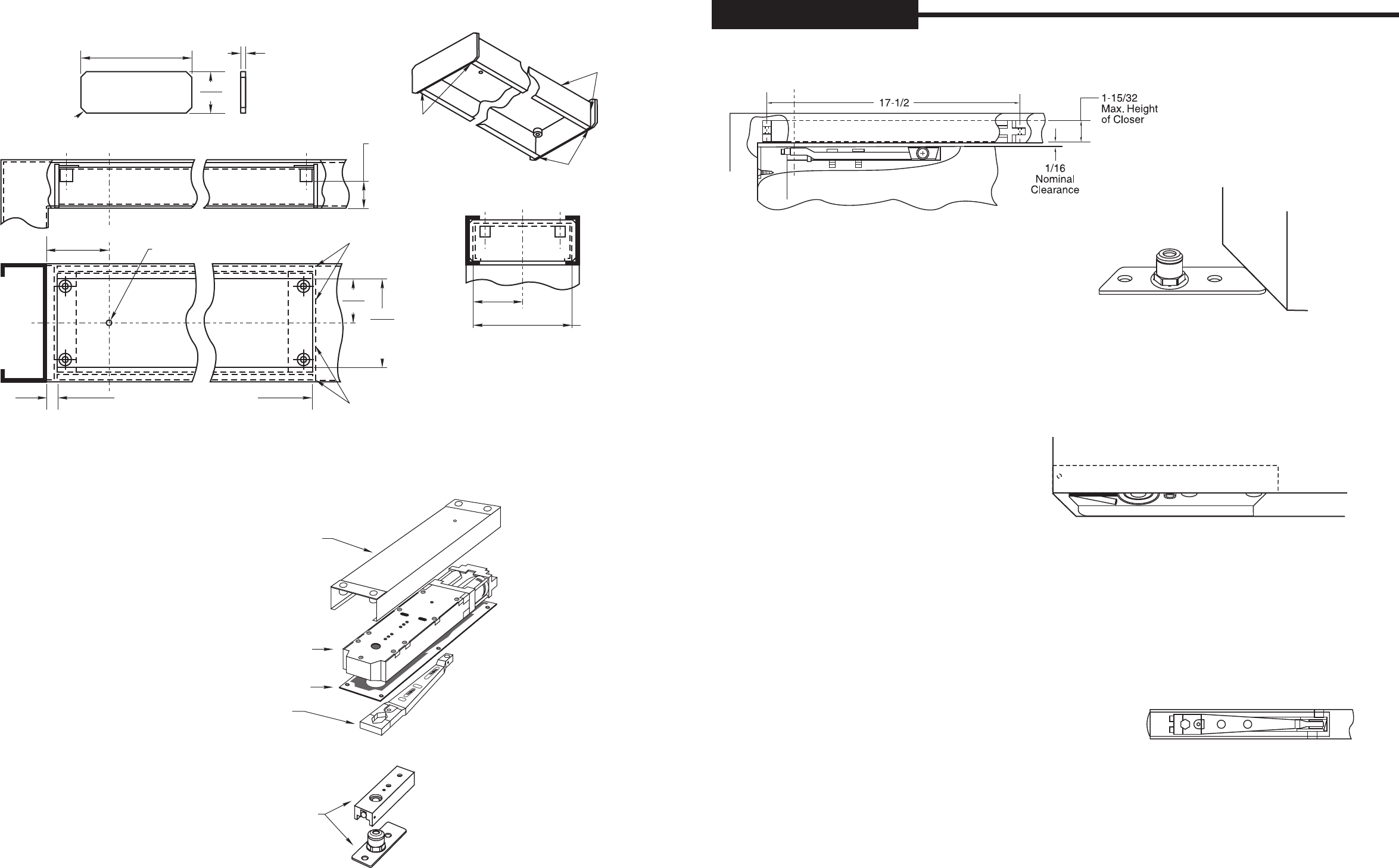
PAGE 3
PAGE 2
Rixson 866-474-9766 Technical Department
www.rixson.com
Rixson 866-474-9766 Technical Department
www.rixson.com
1. Install mounting channel in frame.
C
LSpindle & Bottom Pivot
2. Install bottom pivot floor portion.
(see 218 instruction sheet)
Installation Instructions
4. Install door portion of bottom pivot.
(see 218 instruction sheet)
JAMB
DOOR
Closer Mounting Channel
Closer Body
Centering Arm
218 Bottom Pivot
Included in package:
5. Install Door. Turn closing speed valves shut (clockwise).
a. Using a suitable wrench, turn spindle of closer to 90°
OR hold open position
b. Slide the door over the 218 pivot, which is attached to
the bottom of the door frame. Making sure the door is
resting on the bottom pivot, tilt the door so that the
opening in the top centering bracket fits into the main
spindle a the top of the door.
c. Install arm clamp making certain that spindle and arm
fit properly. Fasten with two 5/16” socket head cap
screws. IMPORTANT: Tighten arm locking screws
securely while working door back and forth.
Cover Plate
Step #1
Reinforcement End Plate
(2 Reqd. by Others)
Side View of Head Frame
1-1/8 (28.6) From Face
of Head Frame to Bottom
of Mounting Posts
Critical Dim.
Step #2
Mounting
Channel
Assembly
Bottom Edges Flush
1/8" (3.2) Dia. Ref.
Over Closer Spindle
18-1/4 (463.6) Cutout for Cover Plate
Underside View of Head Frame
Weld both end plates
to inside of head frame.
See Note 5
Weld both end plates
to mounting channel securely
on sides and top.
3-3/4
(95.2)
Cutout
for Cover
Plate
1-7/8
(47.6)
Step #3
Head Frame
Installation
C
LDoor &
Mounting
Channel NOTES:
1. Do not scale drawing.
2. Right hand door shown.
3. Minimum width head frame 2" x 5-
1/2" (50.8 x 139.7)16 ga. max.
4. All dimensions given in inches (mm).
5. Channel must be installed prior to
jobsite installation of frame.
2-5/32
(54.8)
4-5/16
(109.5)
Max. Width
of Mounting
Channel
C
LCloser
Spindle
End View of Head Frame
192 Hollow Metal Mounting Channel
This dimension to be a
slip fit into inside width
of head frame. 3/16
(4.8)
1-3/4
(44.4)
1/8 (3.2) x 45° CHMF.
C
LCloser Spindle
Weld both end
plates to mounting
channel securely on
sides and top.
Bottom Edges Flush
2-3/4
(69.8)
1/2
(12.7)
3. Install wood door arm plate using #14 x 1-1/2
FHWS. Install main arm using (2) 1/4 x 20 x 7/8"
hex head arm screws. Drill (2) each 15/32 holes
for centering screws, where shown on template.
Do not tighten arm or centering screws.
