Robert Bosch NBC-265-W WIRELESS IP CAMERA User Manual NBC 255 W en
Robert Bosch Taiwan Co., Ltd. WIRELESS IP CAMERA NBC 255 W en
Contents
- 1. Users Manual 255 1
- 2. Users Manual 255 2
- 3. Users Manual 265 1
- 4. Users Manual 265 2
Users Manual 255 1
Wireless IP Camera
NBC-255-W
en Installation and Operation Manual

IP Camera 200 Series Table of Contents | en 3
Bosch Security Systems Installation and Operation Manual AR18-10-B012 | v1.54 | 2011.07
Table of Contents
1Safety 8
1.1 Safety precautions 8
1.2 Important safety instructions 9
1.3 FCC & ICES compliance 10
1.4 UL certification 11
1.5 Bosch notices 11
1.6 Copyrights 12
2 Introduction 13
2.1 Features 13
2.2 Unpacking 15
3 Installation 17
3.1 Wireless antenna 17
3.2 SD card 18
3.3 Mounting the camera 21
3.5 Network connector 25
3.6 Power connection 26
3.6.1 DC power connection 26
3.7 I/O connector 28
3.8 Audio connectors 30
3.9 Resetting the camera 31
4 Browser connection 58
4.1 System requirements 58
4.2 Establishing the connection 58
4.2.1 Password protection in camera 59
4.3 Protected network 59
4.4 Connection established 60
4.4.1 LIVEPAGE 61
4.4.2 RECORDINGS 62
4.4.3 SETTINGS 62

4en | Table of Contents IP Camera 200 Series
AR18-10-B012 | v1.54 | 2011.07 Installation and Operation Manual Bosch Security Systems
5 Basic Mode 63
5.1 Basic Mode menu tree 63
5.2 Device Access 64
5.2.1 Camera name 64
5.2.2 Password 64
5.3 Date/Time 65
5.4 Network 66
5.5 Encoder 67
5.6 Audio 67
5.7 Recording 67
5.7.1 Storage medium 67
5.8 System Overview 67
6 Advanced Mode 68
6.1 Advanced Mode menu tree 68
6.2 General 69
6.2.1 Identification 69
6.2.2 Password 69
6.2.3 Date/Time 71
6.2.4 Display Stamping 72
6.3 Web Interface 74
6.3.1 Appearance 74
6.3.2 LIVEPAGE Functions 75
6.3.3 Logging 76
6.4 Camera 77
6.4.1 Installer Menu 77
6.4.2 Picture Settings 78
6.4.4 Encoder Profile 84
6.4.5 Encoder Streams 88
6.4.6 Audio 89
6.5 Recording 90
6.5.1 Storage Management 91
6.5.2 Recording Profiles 95
6.5.3 Retention Time 97
6.5.4 Recording Scheduler 98
6.5.5 Recording Status 99

IP Camera 200 Series Table of Contents | en 5
Bosch Security Systems Installation and Operation Manual AR18-10-B012 | v1.54 | 2011.07
6.6 Alarm 100
6.6.1 Alarm Connections 100
6.6.2 Video Content Analyses (VCA) 103
6.6.3 VCA configuration- Profiles 104
6.6.4 VCA configuration - Scheduled 110
6.6.5 VCA configuration - Event triggered 112
6.6.6 Audio Alarm 113
6.6.7 Alarm E-Mail 114
6.7 Interfaces 117
6.7.1 Alarm input 117
6.7.2 Relay 117
6.8 Network 119
6.8.1 Network Access 119
6.8.2 Advanced 123
6.8.3 WLAN 124
6.8.4 Multicast 125
6.8.5 FTP Posting 126
6.9 Service 128
6.9.1 Maintenance 128
6.9.2 System Overview 130
7 Operation via the browser 131
7.1 Livepage 131
7.1.1 Processor load 132
7.1.2 Image selection 133
7.1.3 Digital I/O 134
7.1.4 System Log / Event Log 135
7.1.5 Saving snapshots 135
7.1.6 Recording video sequences 135
7.1.7 Running recording program 135
7.1.8 Audio communication 136
7.2 Recordings page 137
7.2.1 Controlling playback 137
8 Troubleshooting 139
8.1 LED indicators 139

6en | Table of Contents IP Camera 200 Series
AR18-10-B012 | v1.54 | 2011.07 Installation and Operation Manual Bosch Security Systems
8.2 Resolving problems 139
8.3 Customer service 140
9 Maintenance 141
9.1 Repairs 141
9.1.1 Transfer and disposal 141
10 Technical Data 142
10.1 Specifications 142
10.1.1 Dimensions 156
10.1.2 Accessories 159
8en | Safety IP Camera 200 Series
AR18-10-B012 | v1.54 | 2011.07 Installation and Operation Manual Bosch Security Systems
1Safety
1.1 Safety precautions
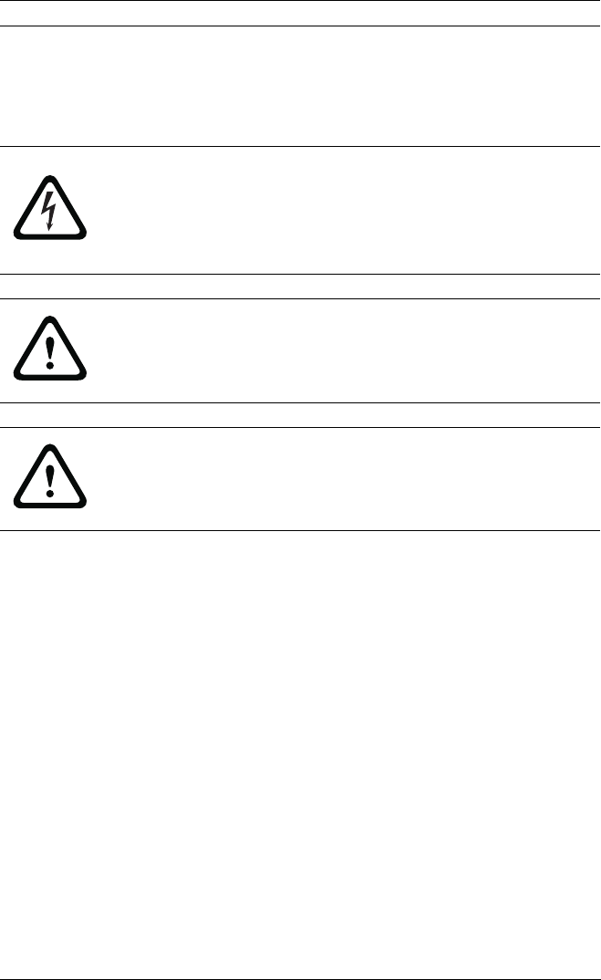
DANGER!
High risk: This symbol indicates an imminently hazardous
situation such as "Dangerous Voltage" inside the product.
If not avoided, this will result in an electrical shock, serious
bodily injury, or death.
WARNING!
Medium risk: Indicates a potentially hazardous situation.
If not avoided, this could result in minor or moderate bodily
injury.
CAUTION!
Low risk: Indicates a potentially hazardous situation.
If not avoided, this could result in property damage or risk of
damage to the device.

IP Camera 200 Series Safety | en 9
Bosch Security Systems Installation and Operation Manual AR18-10-B012 | v1.54 | 2011.07
1.2 Important safety instructions
Read, follow, and retain for future reference all of the following
safety instructions. Heed all warnings on the unit and in the
operating instructions before operating the unit.
1. Cleaning - Generally, using a dry cloth for cleaning is
sufficient but a moist, fluff-free cloth or leather shammy
may also be used. Do not use liquid cleaners or aerosol
cleaners.
2. Heat Sources - Do not install the unit near any heat
sources such as radiators, heaters, stoves, or other
equipment (including amplifiers) that produce heat.
3. Water - Never spill liquid of any kind on the unit.
4. Lightning - Take precautions to protect the unit from
power and lightning surges.
5. Controls adjustment - Adjust only those controls specified
in the operating instructions. Improper adjustment of
other controls may cause damage to the unit.
6. Power sources - Operate the unit only from the type of
power source indicated on the label.
7. Servicing - Unless qualified, do not attempt to service this
unit yourself. Refer all servicing to qualified service
personnel.
8. Replacement parts - Use only replacement parts specified
by the manufacturer.
9. Installation - Install in accordance with the manufacturer's
instructions and in accordance with applicable local codes.
10. Attachments, changes or modifications - Only use
attachments/accessories specified by the manufacturer.
Any change or modification of the equipment, not
expressly approved by Bosch, could void the warranty or,
in the case of an authorization agreement, authority to
operate the equipment.

10 en | Safety IP Camera 200 Series
AR18-10-B012 | v1.54 | 2011.07 Installation and Operation Manual Bosch Security Systems
1.3 FCC & ICES compliance
FCC & ICES Information
This equipment has been tested and found to comply with the
limits for a Class B digital device, pursuant to part 15 of the
FCC Rules. These limits are designed to provide reasonable
protection against harmful interference in a residential
installation. This equipment generates, uses, and can radiate
radio frequency energy and, if not installed and used in
accordance with the instructions, may cause harmful
interference to radio communications. However, there is no
guarantee that interference will not occur in a particular
installation. If this equipment does cause harmful interference
to radio or television reception, which can be determined by
turning the equipment off and on, the user is encouraged to try
to correct the interference by one or more of the following
measures:
– reorient or relocate the receiving antenna;
– increase the separation between the equipment and
receiver;
– connect the equipment into an outlet on a circuit different
from that to which the receiver is connected;
– consult the dealer or an experienced radio/TV technician
for help.
This device complies with part 15 of the FCC Rules. Operation
is subject to the following two conditions:
1. this device may not cause harmful interference, and
2. this device must accept any interference received,
including interference that may cause undesired operation.
Intentional or unintentional modifications, not expressly
approved by the party responsible for compliance, shall not be
made. Any such modifications could void the user's authority to
operate the equipment. If necessary, the user should consult
the dealer or an experienced radio/television technician for
corrective action.

IP Camera 200 Series Safety | en 11
Bosch Security Systems Installation and Operation Manual AR18-10-B012 | v1.54 | 2011.07
The user may find the following booklet, prepared by the
Federal Communications Commission, helpful: How to Identify
and Resolve Radio-TV Interference Problems. This booklet is
available from the U.S. Government Printing Office,
Washington, DC 20402, Stock No. 004-000-00345-4.
FCC RF Radiation Exposure Statement
The equipment complies with RF exposure limits set forth for
an uncontrolled environment.
The antenna(s) used for this transmitter must not be co-located
or operating in conjunction with any other antenna or
transmitter.
1.4 UL certification
Disclaimer
Underwriter Laboratories Inc. ("UL") has not tested the
performance or reliability of the security or signaling aspects of
this product. UL has only tested fire, shock and/or casualty
hazards as outlined in UL's Standard(s) for Safety for Closed
Circuit Television Equipment, UL 2044. UL Certification does not
cover the performance or reliability of the security or signaling
aspects of this product.
UL MAKES NO REPRESENTATIONS, WARRANTIES, OR
CERTIFICATIONS WHATSOEVER REGARDING THE
PERFORMANCE OR RELIABILITY OF ANY SECURITY OR
SIGNALING RELATED FUNCTIONS OF THIS PRODUCT.
12 en | Safety IP Camera 200 Series
AR18-10-B012 | v1.54 | 2011.07 Installation and Operation Manual Bosch Security Systems
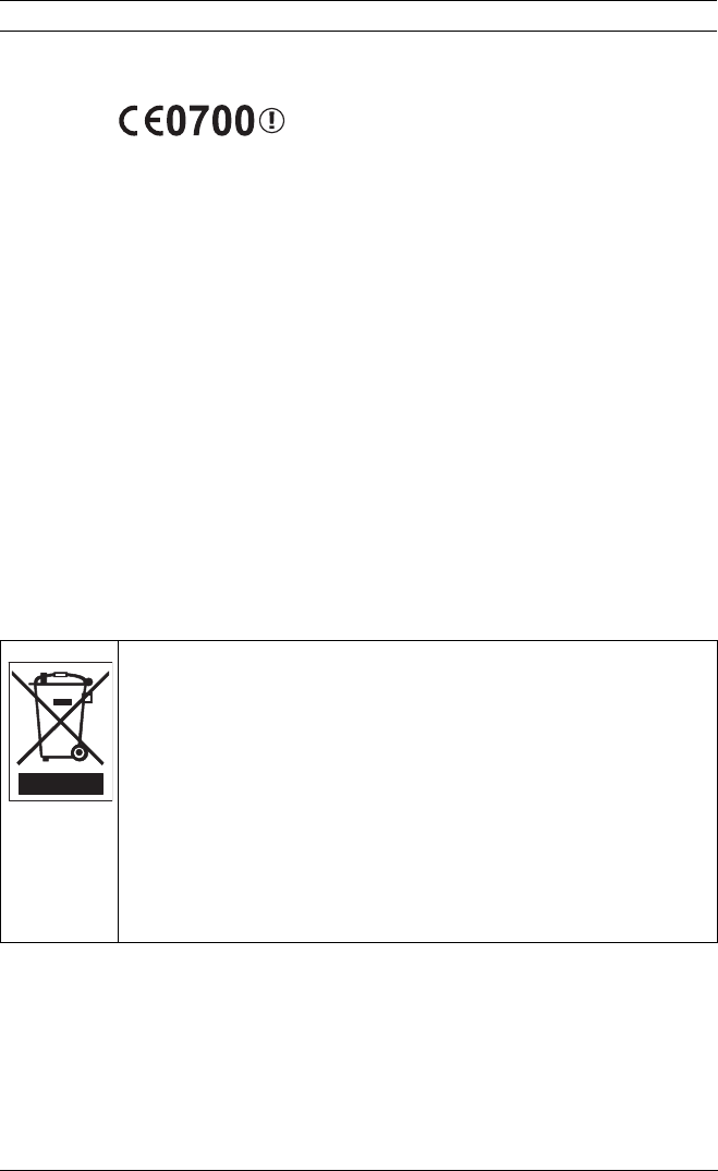
1.5 CE certification
This indicates compliance with the R&TTE Directive 1999/5/EC
and meets the relevant parts of following technical
specifications:
ETSI EN 300 328 V1.7.1:2006
ETSI EN301489-17 V2.1.1:2009
ETSI EN301489-1 V1.8.1:2008
IEC60950-1:2005+A1:2009
EN60950-1:2006+A11:2009
EN 62311:2008
This equipment complies with CE RF radiation exposure limits
set forth for an uncontrolled environment.
This equipment should be installed and operated with a
minimum distance of 20 centimeters between the radiator and
your body.
1.6 Bosch notices
More information
For more information please contact the nearest Bosch Security
Systems location or visit www.boschsecurity.com
Disposal - Your Bosch product was developed and
manufactured with high-quality material and components that
can be recycled and reused. This symbol means that
electronic and electrical appliances, which have reached the
end of their working life, must be collected and disposed of
separately from household waste material. Separate collecting
systems are usually in place for disused electronic and
electrical products. Please dispose of these devices at an
environmentally compatible recycling facility, per European
Directive 2002/96/EC

IP Camera 200 Series Safety | en 13
Bosch Security Systems Installation and Operation Manual AR18-10-B012 | v1.54 | 2011.07
1.7 Copyrights
The firmware 4.1 uses the fonts "Adobe-Helvetica-Bold-R-
Normal--24-240-75-75-P-138-ISO10646-1" and "Adobe-
Helvetica-Bold-R-Normal--12-120-75-75-P-70-ISO10646-1" under
the following copyright:
Copyright 1984-1989, 1994 Adobe Systems Incorporated.
Copyright 1988, 1994 Digital Equipment Corporation.
Permission to use, copy, modify, distribute and sell this
software and its documentation for any purpose and without
fee is hereby granted, provided that the above copyright
notices appear in all copies and that both those copyright
notices and this permission notice appear in supporting
documentation, and that the names of Adobe Systems and
Digital Equipment Corporation not be used in advertising or
publicity pertaining to distribution of the software without
specific, written prior permission.
This software is based in part on the work of the Independent
JPEG Group.

IP Camera 200 Series Introduction | en 13
Bosch Security Systems Installation and Operation Manual AR18-10-B012 | v1.54 | 2011.07
2 Introduction
2.1 Features
This WLAN IP camera is a ready-to-use, complete network video
surveillance system inside a compact camera. The camera
offers a cost-effective solution for a broad range of
applications. It uses H.264 compression technology to give
clear images reducing bandwidth and storage.The camera can
be used as a stand-alone video surveillance system with no
additional equipment or it can easily integrate with the Bosch
DVR 700 Series recorders.
Features include:
– Removable SD/SDHC card offers days of storage inside
camera
– Tri-streaming: Two H.264 streams and one M-JPEG stream
– Progressive scan for sharp images of moving objects
– Two-way audio and audio alarm
– Tamper and motion detection
– Conforms to the ONVIF standard for wide compatibility
– Wireless LAN connection
14 en | Introduction IP Camera 200 Series
AR18-10-B012 | v1.54 | 2011.07 Installation and Operation Manual Bosch Security Systems
2.2 Unpacking
Unpack carefully and handle the equipment with care.
The packaging contains:
– IP camera with lens
– Universal power supply with US, EU and UK plug
– SD card
– Camera mount kit
– Quick installation guide
–CD ROM
– Bosch Video Client
– Documentation
–Tools
– Wireless antenna
If equipment has been damaged during shipment, repack it in
the original packaging and notify the shipping agent or supplier.
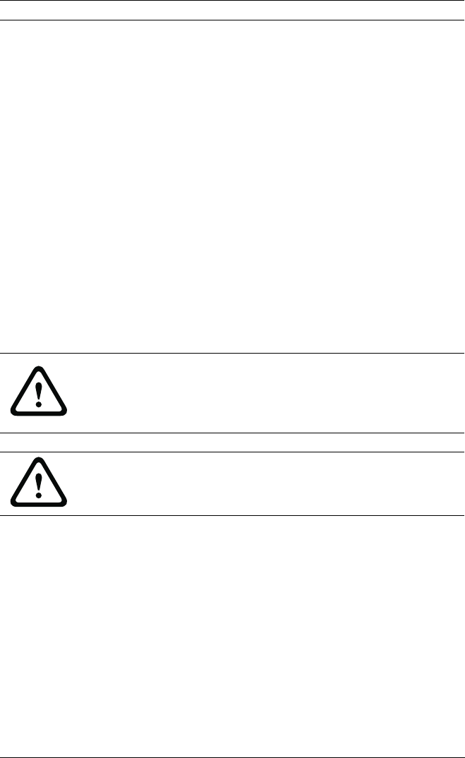
WARNING!
Installation should only be performed by qualified service
personnel in accordance with the National Electrical Code or
applicable local codes.
CAUTION!
The camera module is a sensitive device and must be handled
carefully.
IP Camera 200 Series Installation | en 17
Bosch Security Systems Installation and Operation Manual AR18-10-B012 | v1.54 | 2011.07
3 Installation
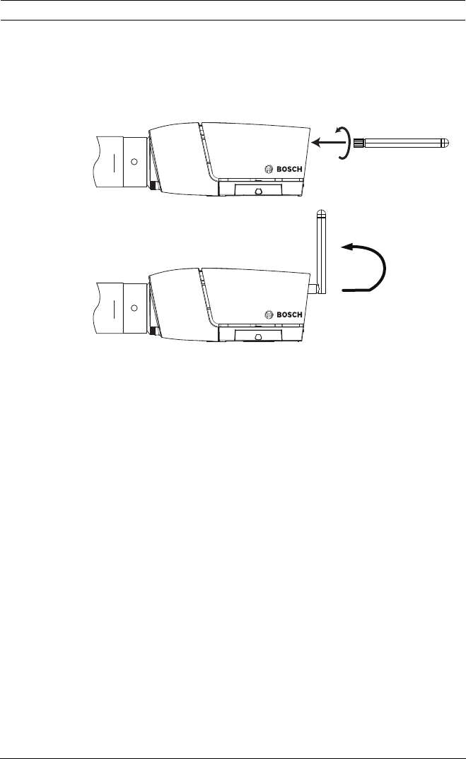
3.1 Wireless antenna
Figure 3.1 Wireless antenna
1. Screw the antenna onto the screw connector on the rear of
the camera.
2. Straighten the antenna.
O
TW
C O
TW
C
18 en | Installation IP Camera 200 Series
AR18-10-B012 | v1.54 | 2011.07 Installation and Operation Manual Bosch Security Systems
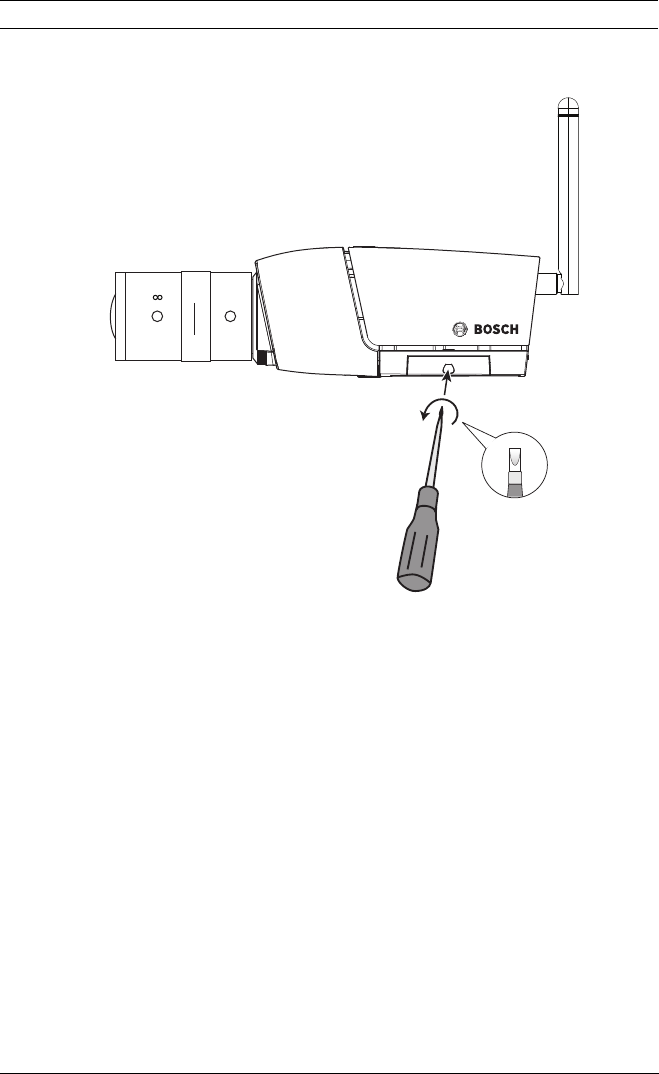
3.2 SD card
Figure 3.2 SD card
1. Unscrew the cover on the right side of the camera.
2. Slide the SD card into the slot.
3. Close and secure the cover.
The camera supports most SD/SDHC cards.
N
O
TW
C
IP Camera 200 Series Installation | en 19
Bosch Security Systems Installation and Operation Manual AR18-10-B012 | v1.54 | 2011.07
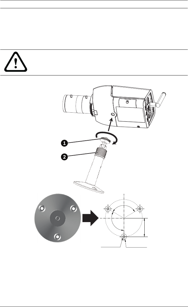
3.3 Mounting the camera
The camera can be mounted either from the top or from the
bottom (1/4"-20 UNC thread). The mounting socket is isolated
from ground to prevent ground loops.
Figure 3.3 Mounting a camera
1. Use three screws to secure the base of the mounting unit
to a wood (Ø3.8 mm, 26 mm deep) or concrete (Ø6 mm,
26 mm deep) surface.
2. On the mounting unit, loosen the ball-socket adjustment
ring (2).
CAUTION!
Do not point the camera/lens into direct sunlight as this may
damage the sensors.
3x Ø3.8 mm
D: 26 mm
3x Ø6 mm
D: 26 mm
120°
120°
27 mm

20 en | Installation IP Camera 200 Series
AR18-10-B012 | v1.54 | 2011.07 Installation and Operation Manual Bosch Security Systems
3. Adjust the ball-socket so that camera mount is correcrly
aligned for the required angle.
4. Screw camera onto mount and, when in position, tighten
the locking ring (1) securely.
5. Tighten the ball-socket adjustment ring (2) securely.
IP Camera 200 Series Installation | en 21
Bosch Security Systems Installation and Operation Manual AR18-10-B012 | v1.54 | 2011.07
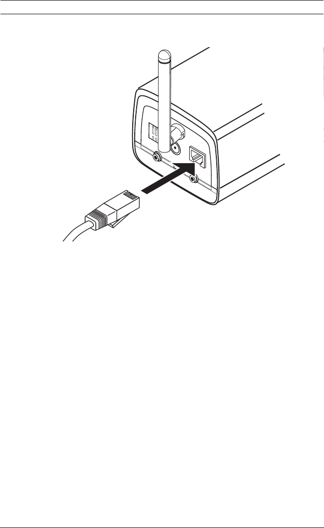
3.4 Network connector
Figure 3.4 Network connection
– Connect the camera to a 10/100 Base-T network.
– Use a shielded UTP Category 5e cable with RJ45
connectors.
1 2 3 4
DC12V Ethernet
Line-out Reset Line-in
I/O
22 en | Installation IP Camera 200 Series
AR18-10-B012 | v1.54 | 2011.07 Installation and Operation Manual Bosch Security Systems
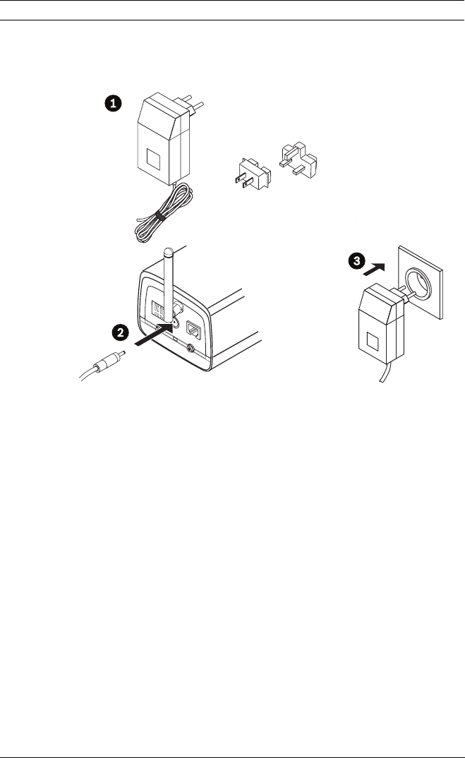
3.5 Power connection
3.5.1 DC power connection
Figure 3.5 DC power connection
1. Slide the plug adapter that matches your outlet socket
onto the supplied power supply.
2. Insert the power connector jack from the power supply
into the DC12V socket of the camera.
3. Connect the power supply to either a 230 VAC or a
120 VAC power supply outlet.
When power is supplied to the camera the LED on the bottom-
front of the camera lights. (This LED can be disabled in the
Installer menu.)
Note:
The date/time must be synchronized each time after power on.
It is important to ensure that the date/time is correct for
recording. An incorrect date/time setting could prevent correct
recording.
1 2 3 4
DC12V Ethernet
Line-out Reset Line-in
I/O
IP Camera 200 Series Installation | en 23
Bosch Security Systems Installation and Operation Manual AR18-10-B012 | v1.54 | 2011.07
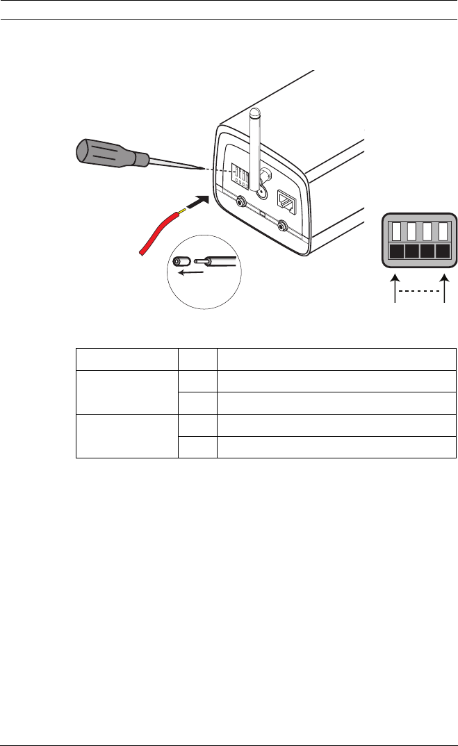
3.6 I/O connector
Figure 3.6 I/O connector pins
– Max. wire diameter AWG 22-28 for both stranded and
solid; cut back 5 mm (0.2 in) of insulation.
– Relay output switching capability: Max. voltage 24 VAC or
24 VDC. Max. 1 A continuous, 12 VA.
– Trigger in: +9 VDC minimum; +30 VDC maximum. Reverse
polarity connection will be inactive.
– Alarm input configurable as active low or active high.
Function Pin I/O socket
Relay 1 Relay out contact 1
2 Relay out contact 2
Alarm input 3 Relay in Positive
4 Relay in Negative
1 2 3 4
DC12V Ethernet
Line-out Reset Line-in
I/O
5 mm
(0.2 in)
I/O
Pin 1 Pin 4
24 en | Installation IP Camera 200 Series
AR18-10-B012 | v1.54 | 2011.07 Installation and Operation Manual Bosch Security Systems
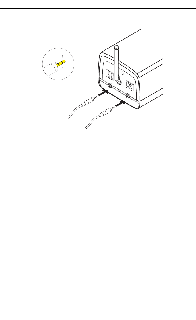
3.7 Audio connectors
Figure 3.7 Audio connectors
Connect audio devices to the Line In and Line Out connectors.
1 2 3 4
DC12V Ethernet
Line-out Reset Line-in
I/O
Line - R
GND
Line - L
Line in: 9 kOhm typ., 200 mVrms
Line out: 16 Ohm min. 200 mVrms
IP Camera 200 Series Installation | en 25
Bosch Security Systems Installation and Operation Manual AR18-10-B012 | v1.54 | 2011.07
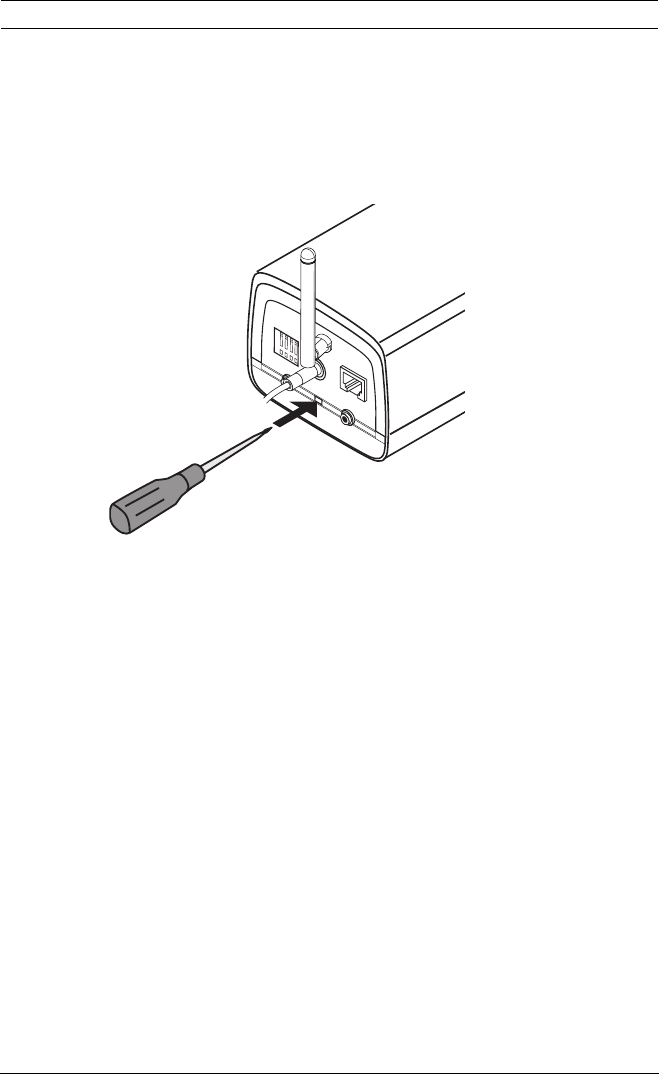
3.8 Resetting the camera
If the camera cannot be connected because the IP address has
changed, press and hold the reset button (7 seconds
approximately) until the LED flashes (red) to recall the factory
default values. The factory default IP address is 192.168.0.1
Figure 3.8 Reset button
1 2 3 4
DC12V Ethernet
Line-out Reset Line-in
I/O

58 en | Browser connection IP Camera 200 Series
AR18-10-B012 | v1.54 | 2011.07 Installation and Operation Manual Bosch Security Systems
4 Browser connection
A computer with Microsoft Internet Explorer can be used to
receive live images from the camera, control cameras, and
replay stored sequences. The camera is configured over the
network using a browser or via the Bosch Video Client
(supplied with the product).
4.1 System requirements
– Microsoft Internet Explorer version 7.0 or higher
– Monitor: resolution at least 1024 × 768 pixels, 16 or 32 bit
color depth
– Intranet or Internet network access
The Web browser must be configured to enable Cookies to be
set from the IP address of the unit.
In Windows Vista, deactivate protected mode on the Security
tab under Internet Options.
To play back live video images, an appropriate ActiveX must be
installed on the computer. If necessary, the required software
and controls can be installed from the product CD provided.
a. Insert the CD into the CD-ROM drive of the computer.
If the CD does not start automatically, open the root
directory of the CD in Windows Explorer and double
click BVC-installer.exe
b. Follow the on-screen instructions.
To get full support for recordings and snapshots, install the
MPEG_ActiveX from the product disk to your computer.

IP Camera 200 Series Browser connection | en 59
Bosch Security Systems Installation and Operation Manual AR18-10-B012 | v1.54 | 2011.07
4.2 Establishing the connection
The camera must be assigned a valid IP address to operate on
your network. The default address pre-set at the factory is
192.168.0.1
1. Start the Web browser.
2. Enter the IP address of the camera as the URL.
Note:
If the connection is not established, the maximum number of
possible connections may already have been reached.
Depending on the device and network configuration, up to 25
web browsers, or 50 Bosch VMS connections are supported.
4.2.1 Password protection in camera
A camera offers the option of limiting access across various
authorization levels. If the camera is password-protected, a
message to enter the password appears.
1. Enter the user name and the associated password in the
appropriate fields.
2. Click OK. If the password is correct, the desired page is
displayed.
4.3 Protected network
If a RADIUS server is used for network access control (802.1x
authentication), the camera must be configured first. To
configure the camera for a Radius network, connect it directly
to a PC via a crossed network cable and configure the two
parameters, Identity and Password. Only after these have been
configured can communication with the camera via the network
occur.
60 en | Browser connection IP Camera 200 Series
AR18-10-B012 | v1.54 | 2011.07 Installation and Operation Manual Bosch Security Systems
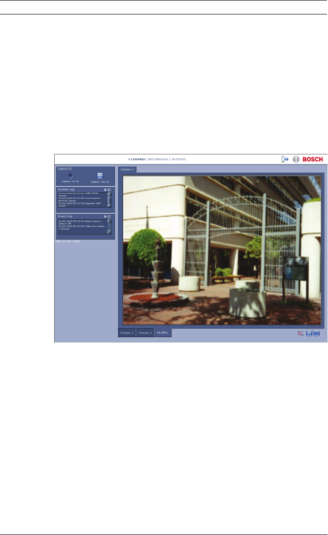
4.4 Connection established
When a connection is established, the LIVEPAGE is initially
displayed. The application title bar displays the type number of
the connected camera and three items: LIVEPAGE,
RECORDINGS, SETTINGS.
Note:
The RECORDINGS link is only visible if a storage medium is
available. (Ensure that MPEG_ActiveX is installed.)
Figure 4.1 Livepage
4.4.1 LIVEPAGE
The LIVEPAGE is used to display and control the video stream.
Refer to Section 7.1 Livepage, page 131 for more information.
4.4.2 RECORDINGS
Click RECORDINGS in the application title bar to open the
playback page. Refer to Section 7.2 Recordings page, page 136
for more information.
4.4.3 SETTINGS
Click SETTINGS in the application title bar to configure the
camera and the application interface. A new page containing

IP Camera 200 Series Browser connection | en 61
Bosch Security Systems Installation and Operation Manual AR18-10-B012 | v1.54 | 2011.07
the configuration menu is opened. All settings (except date/
time) are stored in the camera memory so that they are
retained, even if the power is interrupted.
Changes that influence the fundamental functioning of the unit
(for example, firmware updates) can only be made using the
configuration menu.
The configuration menu tree allows all parameters of the unit to
be configured. The configuration menu is divided into Basic
Mode and Advanced Mode.
Refer to Section 5 Basic Mode, page 63 for more information on
basic settings; refer to Section 6 Advanced Mode, page 68 for
more information on advanced settings.
Note:
It is recommended that only expert users or system
administrators use the Advanced Mode.

IP Camera 200 Series Basic Mode | en 63
Bosch Security Systems Installation and Operation Manual AR18-10-B012 | v1.54 | 2011.07
5 Basic Mode
5.1 Basic Mode menu tree
The basic mode configuration menu allows a set of basic
camera parameters to be configured.
To view the current settings:
1. If necessary, click the Basic Mode menu to expand it. The
sub-menus are displayed.
2. Click a sub-menu. The corresponding page is opened.
The settings are changed by entering new values or by selecting
a pre-defined value in a list field.
Saving changes
After making changes in a window, click Set to send the new
settings to the device and save them there.
Clicking Set saves only the settings in the current window.
Changes in any other windows are ignored.
Click SETTINGS in the applications title bar to close the
window without saving the changes.
Note:
When entering names do not use any special characters, for
example &. Special characters are not supported by the internal
recording management system.
Basic Mode
> Device Access
> Date/Time
> Network
> Encoder
> Audio
> Recording
> System Overview

64 en | Basic Mode IP Camera 200 Series
AR18-10-B012 | v1.54 | 2011.07 Installation and Operation Manual Bosch Security Systems
5.2 Device Access
5.2.1 Camera name
The camera can be assigned a name to assist in identifying it.
The name simplifies the management of multiple devices in
more extensive systems.
The camera name is used for remote identification, for example,
in the event of an alarm. Enter a name that makes it as easy as
possible to identify the location unambiguously.
5.2.2 Password
A password prevents unauthorized access to the device. The
device recognizes three authorization levels: service, user, and
live.
–service is the highest authorization level. Entering the
correct password gives access to all the functions of the
camera and allows all configuration settings to be
changed.
–user is the middle authorization level. This user can
operate the device, play back recordings, and also control
a camera but cannot change the configuration.
–live is the lowest authorization level. It can only be used to
view the live video image and switch between the different
live image displays.
Use the various authorization levels to limit access. Proper
password protection is only guaranteed if all higher
authorization levels are also protected with a password. For
example, if a live password is assigned, a service and a user
password should also be set. When assigning passwords,
always start from the highest authorization level, service, and
use different passwords.
Password
Define and change a separate password for each level while
logged in as service or if the device is not protected by a
password. Enter the password (19 characters maximum) for
the selected level.

IP Camera 200 Series Basic Mode | en 65
Bosch Security Systems Installation and Operation Manual AR18-10-B012 | v1.54 | 2011.07
Confirm password
Re-enter the new password to ensure that there are no typing
mistakes.
The new password is only saved after clicking Set. Therefore,
click Set immediately after entering and confirming the
password, even if you plan to assign a password at another
level.
5.3 Date/Time
Device date, time and zone
If there are multiple devices operating in the system or
network, it is important to synchronize their internal clocks. For
example, it is only possible to identify and correctly evaluate
simultaneous recordings when all devices are operating on the
same time.
As the device time is controlled by the internal clock, it is not
necessary to enter the day or date of the week. These are set
automatically. The time zone in which the system is located is
also set automatically.
Click Sync to PC to apply the system time from your
computer to the device.
Note:
It is important to ensure that the date/time is correct for
recording. An incorrect date/time setting could prevent correct
recording.

66 en | Basic Mode IP Camera 200 Series
AR18-10-B012 | v1.54 | 2011.07 Installation and Operation Manual Bosch Security Systems
5.4 Network
Use the settings on this page to integrate the device into a
network. Some changes only take effect after a reboot. In this
case, the Set button changes to Set and Reboot.
1. Make the desired changes.
2. Click Set and Reboot.
– The device is rebooted and the changed settings are
activated. If the IP address, subnet mask, or gateway
address is changed, then the device is only available
under the new addresses after the reboot.
DHCP
If the network has a DHCP server for dynamic IP address
allocation, set this parameter to On to activate the automatic
acceptance of DHCP-assigned IP addresses.
Note:
Certain applications (for example, Bosch Video Management
System) use the IP address for the unique assignment of the
device. If using these applications, the DHCP server must
support the fixed assignment between IP address and MAC
address, and must be appropriately set up so that, once an IP
address is assigned, it is retained each time the system is
rebooted.
IP address
Enter the desired IP address for the camera. The IP address
must be valid for the network.
Subnet mask
Enter the appropriate subnet mask for the set IP address.
Gateway address
Enter the IP address of the gateway to establish a connection to
a remote location in a different subnet. Otherwise, this field can
remain empty (0.0.0.0).

IP Camera 200 Series Basic Mode | en 67
Bosch Security Systems Installation and Operation Manual AR18-10-B012 | v1.54 | 2011.07
5.5 Encoder
Select a profile for encoding the video signal. Pre-programmed
profiles are available that give priority to different parameters.
When a profile is selected, its details are displayed.
Main frequency and Operation environment
Select 50 Hz or 60 Hz as the main frequency, and Indoor or
Outdoor for the operation environment.
5.6 Audio
Switch the camera microphone On or Off.
5.7 Recording
Record the images from the camera to a storage medium. For
long-term authoritative images, it is essential to use an NVR or
an appropriately sized iSCSI system.
5.7.1 Storage medium
1. Select the required storage medium from the list.
2. Click Start to start recording or Stop to end recording.
5.8 System Overview
This page provides general information on the hardware and
firmware system, including version numbers. No items can be
changed on this page but they can be copied for information
purposes when troubleshooting.

68 en | Advanced Mode IP Camera 200 Series
AR18-10-B012 | v1.54 | 2011.07 Installation and Operation Manual Bosch Security Systems
6 Advanced Mode
6.1 Advanced Mode menu tree
The advanced mode configuration menu contains all camera
parameters that can be configured.
To view the current settings:
1. Click the Advanced Mode menu to expand it. The
associated menu sub-headings are displayed.
2. Click a menu sub-heading to expand it.
3. Click a sub-menu. The corresponding page is opened.
The settings are changed by entering new values or by selecting
a pre-defined value in a list field.
Saving changes
After making changes in a window, click Set to send the new
settings to the device and save them there.
Clicking Set saves only the settings in the current window.
Changes in any other windows are ignored.
Click SETTINGS in the applications title bar to close the
window without saving the changes made.
Note:
When entering names do not use any special characters, for
example &. Special characters are not supported by the internal
recording management system.
Advanced Mode
> General
> Web Interface
> Camera
>Recording
>Alarm
> Interfaces
>Network
> Service

IP Camera 200 Series Advanced Mode | en 69
Bosch Security Systems Installation and Operation Manual AR18-10-B012 | v1.54 | 2011.07
6.2 General
6.2.1 Identification
Camera ID
Each camera should be assigned a unique identifier that can be
entered here as an additional means of identification.
Camera name
Assign a camera name to assist in identifying it. The name
simplifies the management of multiple devices in more
extensive systems, for example the VIDOS or Bosch VMS
software. The camera name is used for remote identification,
for example, in the event of an alarm. Enter a name that makes
it as easy as possible to identify the location unambiguously.
Initiator extension
Add text to an initiator name to make identification easier in
large iSCSI systems. This text is added to the initiator name,
separated from it by a full stop.
6.2.2 Password
A password prevents unauthorized access to the device. The
device recognizes three authorization levels: service, user, and
live.
–service is the highest authorization level. Entering the
correct password gives access to all the functions of the
camera and allows all configuration settings to be
changed.
–user is the middle authorization level. This user can
operate the device, play back recordings, and also control
a camera but cannot change the configuration.
General
> Identification
> Password
> Date/Time
> Display Stamping

70 en | Advanced Mode IP Camera 200 Series
AR18-10-B012 | v1.54 | 2011.07 Installation and Operation Manual Bosch Security Systems
–live is the lowest authorization level. It can only be used to
view the live video image and switch between the different
live image displays.
Use the various authorization levels to limit access. Proper
password protection is only guaranteed if all higher
authorization levels are also protected with a password. For
example, if a live password is assigned, a service and a user
password should also be set. When assigning passwords,
always start from the highest authorization level, service, and
use different passwords.
Password
Define and change a separate password for each level while
logged in as service or if the device is not protected by a
password. Enter the password (19 characters maximum) for
the selected level.
Confirm password
Re-enter the new password to ensure that there are no typing
mistakes.
The new password is only saved after clicking Set. Therefore,
click Set immediately after entering and confirming the
password, even if assigning a password at another level.

IP Camera 200 Series Advanced Mode | en 71
Bosch Security Systems Installation and Operation Manual AR18-10-B012 | v1.54 | 2011.07
6.2.3 Date/Time
Date format
Select the required date format.
Device date / Device time
If there are multiple devices operating in your system or
network, it is important to synchronize their internal clocks. For
example, it is only possible to identify and correctly evaluate
simultaneous recordings when all devices are operating on the
same time.
1. Enter the current date. Since the device time is controlled
by the internal clock, it is not necessary to enter the day of
the week – it is added automatically.
2. Enter the current time or click Sync to PC to apply the
system time from your computer to the device.
Note:
It is important to ensure that the date/time is correct for
recording. An incorrect date/time setting could prevent correct
recording.
Device time zone
Select the time zone in which the system is located.
Daylight saving time
The internal clock can switch automatically between normal
and daylight saving time (DST). The device already contains the
data for DST switch-overs up to the year 2015. Use this data or
create alternative time saving data, if required.
First, check the time zone setting. If it is not correct, select the
appropriate time zone for the system:
1. Click Set.
2. Click Details. A new window opens showing an empty
table.
3. Click Generate to fill the table with the preset values from
the camera.
4. Select the region or the city which is closest to the
system's location from the list box below the table.

72 en | Advanced Mode IP Camera 200 Series
AR18-10-B012 | v1.54 | 2011.07 Installation and Operation Manual Bosch Security Systems
5. Click one of the entries in the table to make changes. The
entry is highlighted.
6. Click Delete to remove the entry from the table.
7. Choose other values from the list boxes under the table, to
change the selected entry. Changes are immediate.
8. If there are empty lines at the bottom of the table, for
example after deletions, add new data by marking the row
and selecting values from the list boxes.
9. When finished, click OK to save and activate the table.
Note:
If a table is not created, there is no automatic switching. When
editing the table, note that values occur in linked pairs (DST
start and end dates).
Time server IP address
The camera can receive the time signal from a time server using
various time server protocols and then use it to set the internal
clock. The device polls the time signal automatically once every
minute. Enter the IP address of a time server.
Time server type
Select the protocol that is supported by the selected time
server. It is recommended to select the SNTP server protocol.
This protocol provides high accuracy and is required for special
applications and future function extensions. Select Time server
if the server uses the RFC 868 protocol.
6.2.4 Display Stamping
Various overlays or stamps in the video image provide
important supplementary information. These overlays can be
enabled individually and arranged on the image in a clear
manner.
Camera name stamping
This field sets the position of the camera name overlay. It can
be displayed at the Top, at the Bottom, or at a position of
choice using the Custom option, or it can be set to Off for no
overlay information.

IP Camera 200 Series Advanced Mode | en 73
Bosch Security Systems Installation and Operation Manual AR18-10-B012 | v1.54 | 2011.07
If the Custom option is selected, enter values in the X and Y
position fields.
Time stamping
This field sets the position of the time and date overlay. It can
be displayed at the Top, at the Bottom, or at a position of
choice using the Custom option, or it can be set to Off for no
overlay information.
If the Custom option is selected, enter values in the X and Y
position fields.
Display milliseconds
If necessary, display milliseconds for Time stamping. This
information can be useful for recorded video images; however,
it does increase the processor's computing time. Select Off if
displaying milliseconds is not needed.
Alarm mode stamping
Select On for a text message to be overlaid in the event of an
alarm. It can be displayed at a position of choice using the
Custom option, or it can be set to Off for no overlay
information.
If the Custom option is selected, enter values in the X and Y
position fields.
Alarm message
Enter the message to be displayed on the image in the event of
an alarm. The maximum text length is 31 characters.
Video watermarking
Select On for the transmitted video images to be watermarked.
After activation, all images are marked with an icon. The icon
indicates if the sequence (live or saved) has been manipulated.

74 en | Advanced Mode IP Camera 200 Series
AR18-10-B012 | v1.54 | 2011.07 Installation and Operation Manual Bosch Security Systems
6.3 Web Interface
6.3.1 Appearance
Adapt the appearance of the web interface and change the
website language to meet your requirements. If necessary,
replace the company's logo (top right) and the device name
(top left) in the top part of the window with individual graphics.
Either GIF or JPEG images can be used. The file paths must
correspond to the access mode (for example,
C:\Images\Logo.gif for access to local files or http://
www.myhostname.com/images/logo.gif for access via the
Internet/Intranet). For access via the Internet/Intranet, there
must be a connection in order to display the image. The image
files are not stored on the camera.
To restore the original graphics, delete the entries in the
Company logo and Device logo fields.
Website language
Select the language for the user interface here.
Company logo
Enter the path to a suitable image in this field. The image can
be stored on a local computer, a local network, or at an Internet
address.
Note:
When the image was stored on a local computer, it can only be
displayed by this local computer.
Device logo
Enter the path for a suitable image for the device logo in this
field. The image can be stored on a local computer, a local
network, or at an Internet address.
Web Interface
> Appearance
> LIVEPAGE
Functions
> Logging

IP Camera 200 Series Advanced Mode | en 75
Bosch Security Systems Installation and Operation Manual AR18-10-B012 | v1.54 | 2011.07
6.3.2 LIVEPAGE Functions
In this window, adapt the Livepage functions to meet your
requirements. Choose from a variety of different options for
displaying information and controls.
1. Mark the check boxes for the functions to be displayed on
the Livepage. The selected elements are checked.
2. Check the Livepage to see how the desired items are
available.
Transmit audio
When selected, the audio from the camera (if on) is sent to the
computer.
Show alarm inputs
The alarm inputs are displayed next to the video image as icons
along with their assigned names. If an alarm is active, the
corresponding icon changes color.
Show relay outputs
The relay output is shown next to the video image as an icon
along with its assigned name. If a relay is switched, the icon
changes color.
Show VCA metadata
When video content analysis (VCA) is activated, additional
information is displayed in the live video stream. For example,
in Motion+ mode, the sensor areas for motion detection are
marked.
Show event log
The event messages are displayed with the date and time in a
field next to the video image.
Show system log
The system messages are displayed with the date and time in a
field next to the video image and provide information about the
establishment and termination of connections, etc.

76 en | Advanced Mode IP Camera 200 Series
AR18-10-B012 | v1.54 | 2011.07 Installation and Operation Manual Bosch Security Systems
Allow snapshots
Specify whether the icon for saving individual images should be
displayed below the live image. Individual images can only be
saved if this icon is visible.
Allow local recording
Specify whether the icon for saving video sequences on the
local memory should be displayed below the live image. Video
sequences can only be saved if this icon is visible.
Path for JPEG and video files
Enter the path for the storage location of individual images and
video sequences saved from the Livepage. If necessary, click
Browse to find a suitable folder.
6.3.3 Logging
Save event log
Select this option to save event messages in a text file on the
local computer. This file can be viewed, edited, and printed
with any text editor or standard office software.
File for event log
Enter the path for saving the event log here. If necessary, click
Browse to find a suitable folder.
Save system log
Select this option to save system messages in a text file on the
local computer. This file can be viewed, edited, and printed
with any text editor or standard office software.
File for system log
Enter the path for saving the system log here. If necessary, click
Browse to find a suitable folder.

IP Camera 200 Series Advanced Mode | en 77
Bosch Security Systems Installation and Operation Manual AR18-10-B012 | v1.54 | 2011.07
6.4 Camera
6.4.1 Installer Menu
Camera LED
Disable the Camera LED on the camera to switch it off.
Mirror image
Enable Mirror image to obtain a vertically flipped image
(around the horizontal axis) of the camera picture.
Main frequency and Operation environment
Select 50 Hz or 60 Hz as the main frequency, and Indoor or
Outdoor for the operation environment.
Exposure/frame rate
–Auto exposure/frame rate: the camera automatically sets
the framerate. The camera tries to maintain the selected
default shutter speed as long as the light level of the scene
permits.
Select a minimum frame rate from 4 to 30 fps.
–Fixed exposure: allows a user-defined shutter time.
Select the shutter speed when exposure control is set to
fixed (1/25, 1/33, 1/50, 1/100 for 50 Hz) or (1/30, 1/40, 1/
60, 1/120 for 60 Hz).
Note:
Shutter time is affected by frame rate in auto framerate mode.
For example, if the frame rate is 30 IPS, the longest shutter
time available is 1/30s.
Camera
> Installer Menu
> Picture Settings
> Encoder Profile
> Encoder Streams
> Audio

78 en | Advanced Mode IP Camera 200 Series
AR18-10-B012 | v1.54 | 2011.07 Installation and Operation Manual Bosch Security Systems
6.4.2 Picture Settings
Contrast (0...255)
Adjusts the contrast of the image.
Saturation (0...255)
Adjusts the color saturation; 0 gives a monochrome image.
Brightness (0...255)
Adjusts the brightness of the image.
White balance
–ATW: Auto tracking white balance allows the camera to
continually adjust for optimal color reproduction.
–In Manual mode the Red, Green, and Blue gain can be
manually set to a desired position.
Apply white balance: Hold puts the ATW on hold and saves the
color settings.
R-gain
The red gain adjustment offsets the factory white point
alignment (reducing red introduces more cyan).
G-gain
The green gain adjustment offsets the factory white point
alignment to optimize the white point.
B-gain
The blue gain adjustment offsets the factory white point
alignment (reducing blue introduces more yellow).
It is only necessary to change the white point offset for special
scene conditions.
Default
Click Default to set all video values to their factory setting.

IP Camera 200 Series Advanced Mode | en 79
Bosch Security Systems Installation and Operation Manual AR18-10-B012 | v1.54 | 2011.07
6.4.3 Encoder Profile
Adapt the video data transmission to the operating environment
(network structure, bandwidth, data structures). The camera
simultaneously generates two H.264 video streams and an
M-JPEG stream. Select the compression settings of these
streams individually, for example, one setting for transmissions
to the Internet and one for LAN connections. The settings are
made individually for each stream.
Define profiles
Eight definable profiles are available. The pre-programmed
profiles give priority to different parameters.
–High resolution 1
VGA resolution with low delay
–High resolution 2
VGA resolution with lower data rate
–Low bandwidth
VGA resolution for low bandwidth connections
–DSL
VGA resolution for DSL connections at 500 kbps maximum
–ISDN (2B)
QVGA resolution for ISDN connections at 100 kbps
maximum
–ISDN (1B)
QVGA resolution for ISDN connections at 50 kbps
maximum
–MODEM
QVGA resolution for analog modem connections at 22 kbps
maximum
–GSM
QVGA resolution for GSM connections

80 en | Advanced Mode IP Camera 200 Series
AR18-10-B012 | v1.54 | 2011.07 Installation and Operation Manual Bosch Security Systems
Profile Configuration
Profiles can be configured for use with the H.264 settings of
encoder streams. Select a profile by clicking the appropriate
tab. Change the name of a profile and individual parameter
values within a profile.
Profiles are rather complex. They include a number of
parameters that interact with one another, so it is generally
best to use the default profiles. Only change a profile if
completely familiar with all the configuration options.
The parameters as a group constitute a profile and are
dependent on one another. If a setting outside the permitted
range for a parameter is entered, the nearest valid value is
substituted when the settings are saved.
Profile name
Enter a new name for the profile here. (Do not use any special
characters, for example &.)
Target bit rate
To optimize utilization of the bandwidth in the network, limit
the bit rate. The target bit rate should be set according to the
desired picture quality for typical scenes with no excessive
motion.
For complex images or frequent changes of image content due
to frequent movements, this limit can temporarily be exceeded
up to the value entered in the Maximum bit rate field.
Maximum bit rate
This maximum bit rate is not exceeded under any
circumstances. Depending on the video quality settings for the
I-frames and P-frames, this can result in individual images being
skipped.
The value entered here must be at least 10% higher than the
value entered in the Target bit rate field. If the value entered
here is too low, it is automatically adjusted.

IP Camera 200 Series Advanced Mode | en 81
Bosch Security Systems Installation and Operation Manual AR18-10-B012 | v1.54 | 2011.07
Encoding interval
The Encoding interval slider determines the interval at which
images are encoded and transmitted. This can be particularly
advantageous with low bandwidths. The image rate in ips
(images per second) is displayed next to the slider.
Video resolution
Select here the desired resolution for the video image. VGA
(640x480) and QVGA (320x240) resolutions are available.
Expert Settings
if necessary, use the expert settings to adapt the I-frame quality
and the P-frame quality to specific requirements. The setting is
based on the H.264 quantization parameter (QP).
GOP structure
Select the structure you require for the Group of Pictures.
Depending on whether you place greater priority on having the
lowest possible delay (IP frames only) or using as little
bandwidth possible, you choose IP, IBP or IBBP.
I-frame distance
Use the slider to set the distance between I-frames to Auto or
to between 3 and 60. An entry of 3 means that every third
image is an I-frame.The lower the number, the more I-frames
are generated.
I-frame quality
This setting adjusts the image quality of the I-frames. The basic
setting Auto automatically adjusts the quality to the settings for
the P-frame video quality. Alternatively, use the slider to set a
value between 9 and 51. The value 9 represents the best image
quality with, if necessary, a lower frame refresh rate depending
on the settings for the maximum data rate. A value of 51 results
in a very high refresh rate and lower image quality.
P-frame quality
This setting adjusts the maximum image quality of the P-frames.
The basic setting Auto automatically adjusts to the optimum
combination of movement and image definition (focus).

82 en | Advanced Mode IP Camera 200 Series
AR18-10-B012 | v1.54 | 2011.07 Installation and Operation Manual Bosch Security Systems
Alternatively, use the slider to set a value between 9 and 51.
The value 9 represents the best image quality with, if necessary,
a lower frame refresh rate depending on the settings for the
maximum data rate. A value of 51 results in a very high refresh
rate and lower image quality.
Default
Click Default to return the profile to the factory default values.

IP Camera 200 Series Advanced Mode | en 83
Bosch Security Systems Installation and Operation Manual AR18-10-B012 | v1.54 | 2011.07
6.4.4 Encoder Streams
Select H.264 Settings
1. Select the codec algorithm for streams 1 and 2. The
following algorithms are available
–H.264 BP+ bit-rate-limited
–H.264 MP SD
2. Select the default profile for streams 1 and 2 from the
eight profiles that have been defined.
The algorithm properties have the following settings:
Preview >>
Previews of streams 1 and 2 can be shown.
1. Click Preview >> to display a preview of the video for
streams 1 and 2. the current profile is shown above the
preview.
2. Click 1:1 Live View below a preview to open a viewing
window for that stream. Various additional items of
information are shown across the top of the window.
3. Click Preview << to close the preview displays.
Note:
Deactivate the display of the video images if the performance of
the computer is adversely affected by the decoding of the data
stream.
H.264 BP+ bit-rate-
limited
H.264 MP SD
CABAC off on
CAVLC on off
GOP structure IP IP
I-frame distance 15 30
Deblocking filter on on
Bit rate limited to 1.2 Mbps
Recommended for Hardware
decoders,
DVR 700 Series
Software decoders,
PTZ and rapid
image movements

84 en | Advanced Mode IP Camera 200 Series
AR18-10-B012 | v1.54 | 2011.07 Installation and Operation Manual Bosch Security Systems
JPEG stream
Set the parmeters for the M-JPEG stream.
– Select the Max. frame rate in images per second (IPS).
– The Picture quality slider allows adjustment of the
M-JPEG image quality from Low to High.
Note:
The M-JPEG resolution follows the highest resolution setting of
either stream 1 or stream 2. For example, if stream 1 is VGA and
stream 2 is QVGA, the JPEG resolution will be VGA. The M-JPEG
frame rate varies depending on system loading.
6.4.5 Audio
Select the microphone or line-in connector as the Audio input
or switch it off. Adjust the Input volume with the slider.
Switch the Audio output On or Off.
Select G.711 or L16 as the audio Recording format. The default
value is G.711. Select L16 if you want better audio quality with
higher sampling rates. This requires approximately eight times
the G.711 bandwith.

IP Camera 200 Series Advanced Mode | en 85
Bosch Security Systems Installation and Operation Manual AR18-10-B012 | v1.54 | 2011.07
6.5 Recording
Record the images from the camera to local storage media or to
an appropriately configured iSCSI system.
SDHC cards are the ideal solution for shorter storage times and
temporary recordings, for example, local buffering in the event
of network interruptions.
Note:
The recording hours table is only an indication for reference, an
actual situation might be different (because of different scenes
or networking status for example).
Recording
> Storage Management
> Recording Profiles
> Retention Time
> Recording Scheduler
> Recording Status
Continuous Recording Hours
Profiles
SDHC card capacity
4GB 8GB 16 GB 32 GB
High resolution 1 (VGA, 30F/S,
H.264 MP, T:2000Kb,
M:4000Kb)
4 h 8 h 16 h 32 h
Low bandwidth (VGA, 30F/S,
H.264 MP, T:700Kb,
M:1500Kb)
11 h 22 h 44 h 88 h
DSL (VGA, 30F/S, H.264 MP,
T:400Kb, M:500Kb)
19 h 38 h 76 h 152h
ISDN (2B) (VGA, 30F/S, H.264
MP, T:80Kb, M:100Kb)
78 h 156 h 312 h 624 h