Robert Bosch NBC-265-W WIRELESS IP CAMERA User Manual NBC 265 W en
Robert Bosch Taiwan Co., Ltd. WIRELESS IP CAMERA NBC 265 W en
UserManual.wiki
>
Robert Bosch
>
NBC-265-W User Manual
>
Users Manual 265 2
Contents
1.
Users Manual 255 1
2.
Users Manual 255 2
3.
Users Manual 265 1
4.
Users Manual 265 2
Users Manual 265 2
Navigation menu
Upload a User Manual
Namespaces
Wiki Guide
HTML
PDF
Info
Views
User Manual
Discussion / Help
Navigation
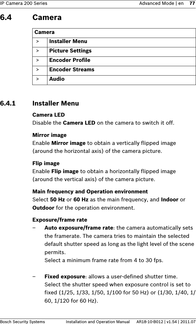
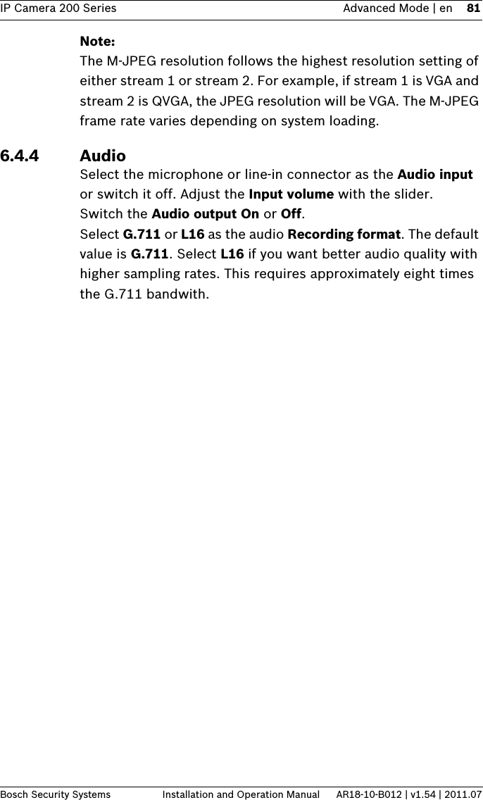
![IP Camera 200 Series Advanced Mode | en 95Bosch Security Systems Installation and Operation Manual AR18-10-B012 | v1.54 | 2011.076.6.3 VCA configuration- ProfilesConfigure two profiles with different VCA configurations. Save profiles on your computer's hard drive and load saved profiles from there. This can be useful if testing a number of different configurations. Save a functioning configuration and test new settings. Use the saved configuration to restore the original settings at any time.1. Select a VCA profile and enter the required settings.2. If necessary, click Default to return all settings to default values.3. Click the Save... to save the profile settings to another file. A new window opens in which to specify the file name and where to save it.4. Click Load... to load a saved profile. A new window opens in which to select the profile file and specify where to save the file.To rename a profile:1. To rename the file, click the icon to the right of the list field and enter the new profile name in the field. (Do not use any special characters, for example &.)2. Click the icon again. The new profile name is saved.The current alarm status is displayed for information purposes.Aggregation time [s]Set an aggregation time of between 0 and 20 seconds. The aggregation time always starts when an alarm event occurs. It extends the alarm event by the value set. This prevents alarm events that occur in quick succession from triggering several alarms and successive events in a rapid sequence. No further alarm is triggered during the aggregation time.The post-alarm time set for alarm recordings only starts once the aggregation time has expired.](https://usermanual.wiki/Robert-Bosch/NBC-265-W.Users-Manual-265-2/User-Guide-1530571-Page-24.png)
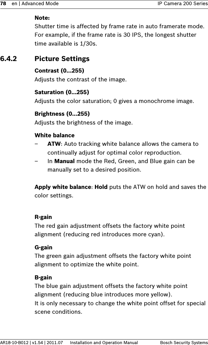
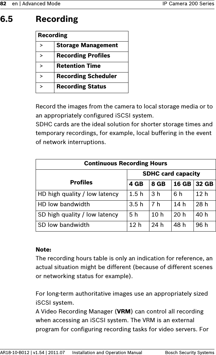
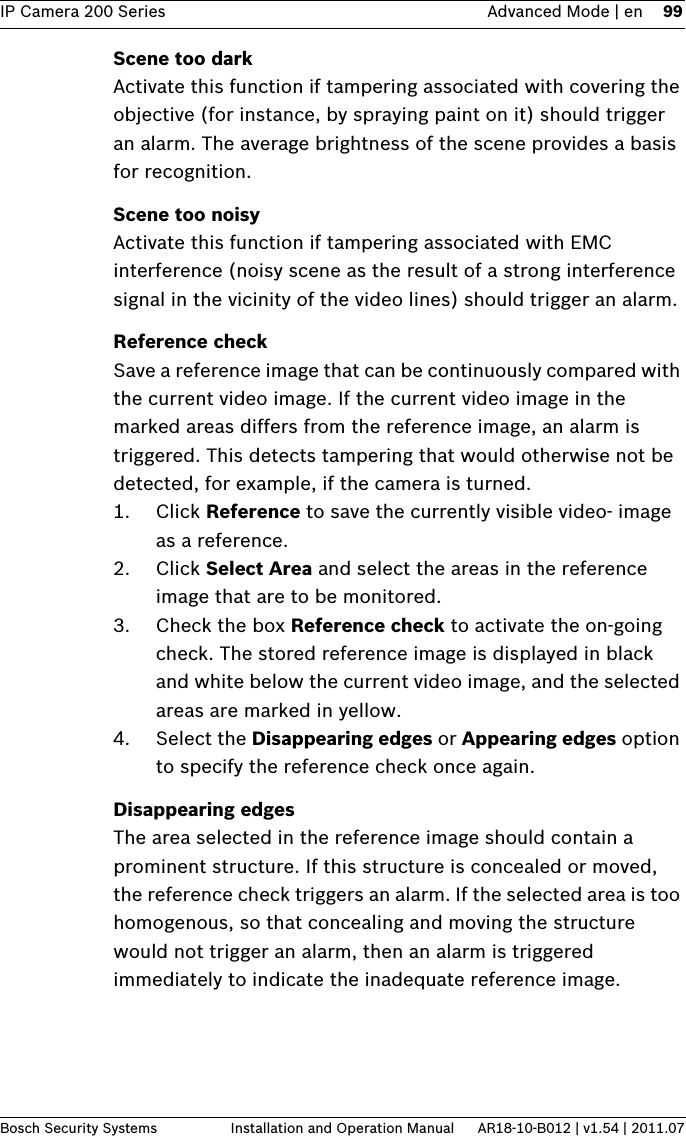
![98 en | Advanced Mode IP Camera 200 SeriesAR18-10-B012 | v1.54 | 2011.07 Installation and Operation Manual Bosch Security SystemsSensitivity and Trigger delay [s] can only be changed if Reference check is selected.SensitivityThe basic sensitivity of the tamper detection can be adjusted for the environmental conditions to which the camera is subject. The algorithm reacts to the differences between the reference image and the current video image. The darker the observation area, the higher the value that must be selected.Trigger delay [s]Set delayed alarm triggering here. The alarm is only triggered after a set time interval in seconds has elapsed and then only if the triggering condition still exists. If the original condition has been restored before this time interval elapses, the alarm is not triggered. This avoids false alarms triggered by short-term changes, for example, cleaning activities in the direct field of vision of the camera.Global change (slider)Set how large the global change in the video image must be for an alarm to be triggered. This setting is independent of the sensor fields selected under Select Area. Set a high value if fewer sensor fields need to change to trigger an alarm. With a low value, it is necessary for changes to occur simultaneously in a large number of sensor fields to trigger an alarm. This option allows detection, independently of motion alarms, manipulation of the orientation or location of a camera resulting from turning the camera mount bracket, for example.Global changeActivate this function if the global change, as set with the Global change slide control, should trigger an alarm.Scene too brightActivate this function if tampering associated with exposure to extreme light (for instance, shining a flashlight directly on the objective) should trigger an alarm. The average brightness of the scene provides a basis for recognition.](https://usermanual.wiki/Robert-Bosch/NBC-265-W.Users-Manual-265-2/User-Guide-1530571-Page-27.png)
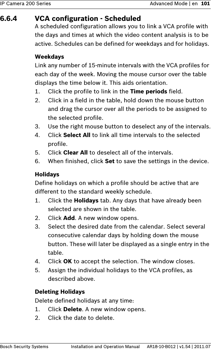
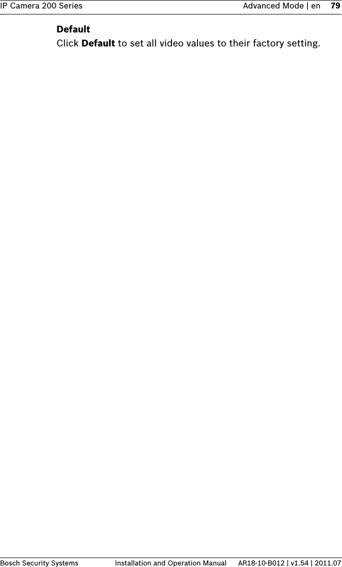
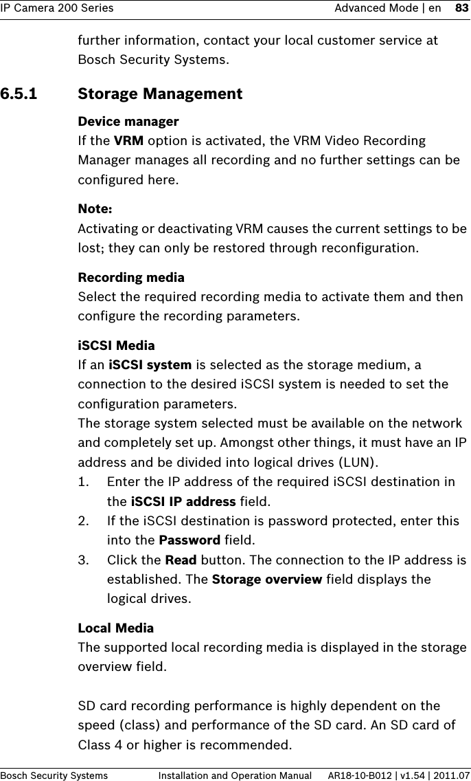
![IP Camera 200 Series Advanced Mode | en 103Bosch Security Systems Installation and Operation Manual AR18-10-B012 | v1.54 | 2011.076.6.5 VCA configuration - Event triggeredThis configuration allows you to stipulate that the video content analysis is only to be activated when triggered by an event. As long as no trigger is activated, the Silent MOTION+ configuration in which metadata is created is active; this metadata facilitates searches of recordings, but does not trigger an alarm.TriggerSelect a physical alarm or a virtual alarm as a trigger. A virtual alarm is created using software, with RCP+ commands or alarm scripts, for example.Trigger activeSelect the VCA configuration here that is to be enabled via an active trigger. A green check mark to the right of the list field indicates that the trigger is active.Trigger inactiveSelect the VCA configuration here that is to be activated if the trigger is not active. A green check mark to the right of the list field indicates that the trigger is inactive.Delay [s]Select the delay period for the reaction of the video content analysis to trigger signals. The alarm is only triggered after a set time interval in seconds has elapsed and then only if the triggering condition still exists. If the original condition has been restored before this time interval elapses, the alarm is not triggered. A delay period may be useful in avoiding false alarms or frequent triggering. During the delay period, the Silent MOTION+ configuration is always enabled.](https://usermanual.wiki/Robert-Bosch/NBC-265-W.Users-Manual-265-2/User-Guide-1530571-Page-32.png)
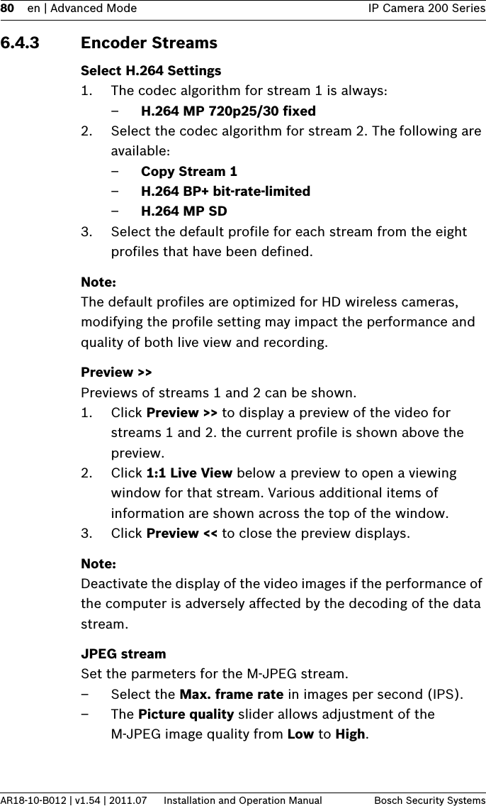
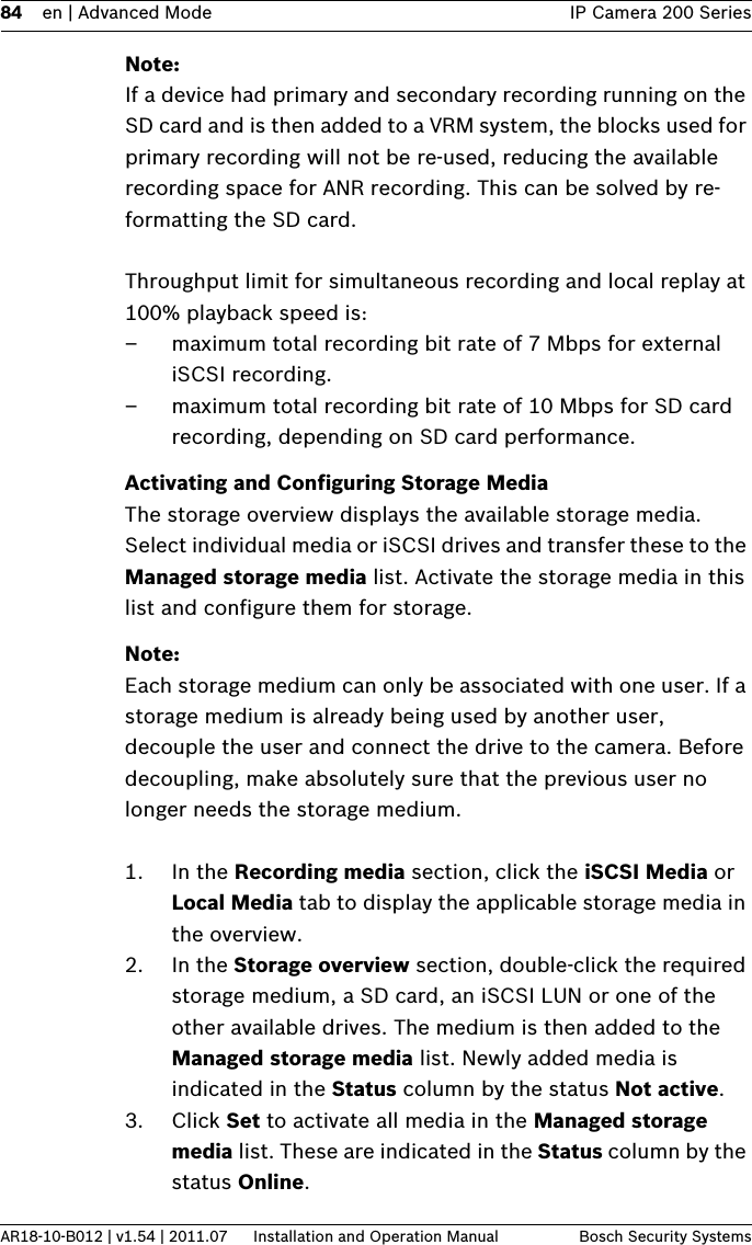
![IP Camera 200 Series Advanced Mode | en 111Bosch Security Systems Installation and Operation Manual AR18-10-B012 | v1.54 | 2011.07deactivates all unencrypted connections allowing connections on the HTTPS port only.RCP+ port 1756Activating RCP+ port 1756 allows unencrypted connections on this port. To allow only encrypted connections, set the Off option to deactivate the port.Telnet supportActivating Telenet support allows unencrypted connections on this port. To allow only encrypted connections, set the Off option to deactivate telnet support, making telnet connections impossible.Interface mode ETHIf necessary, select the Ethernet link type for interface ETH. Depending on the device connected, it may be necessary to select a special operation type.Network MSS [Byte]Set the maximum segment size for the IP packet's user data here. This gives the option to adjust the size of the data packets to the network environment and to optimize data transmission. Please comply with the MTU value of 1,514 bytes in UDP mode.iSCSI MSS [Byte]Specify a higher MSS value for a connection to the iSCSI system than for the other data traffic via the network. The potential value depends on the network structure. A higher value is only useful if the iSCSI system is located in the same subnet as the camera.Enable DynDNSDynDNS.org is a DNS hosting service that stores IP addresses in a database ready for use. It allows selecting the device via the Internet using a host name, without having to know the current IP address of the device. Enable this service here. To do this, obtain an account with DynDNS.org and register the required host name for the device on that site.](https://usermanual.wiki/Robert-Bosch/NBC-265-W.Users-Manual-265-2/User-Guide-1530571-Page-40.png)