Robertshaw Controls d b a Invensys Home Control Systems EMSL-200 Wireless Load Control Meter User Manual TD2001
Robertshaw Controls Company d/b/a Invensys Home Control Systems Wireless Load Control Meter TD2001
User Manual
TD2001 COPYRIGHT© 2002 INVENYS HOME CONTROL SYSTEMS 8/6/02
vLR1
Invensys RF Load Control Meter
General Instructions
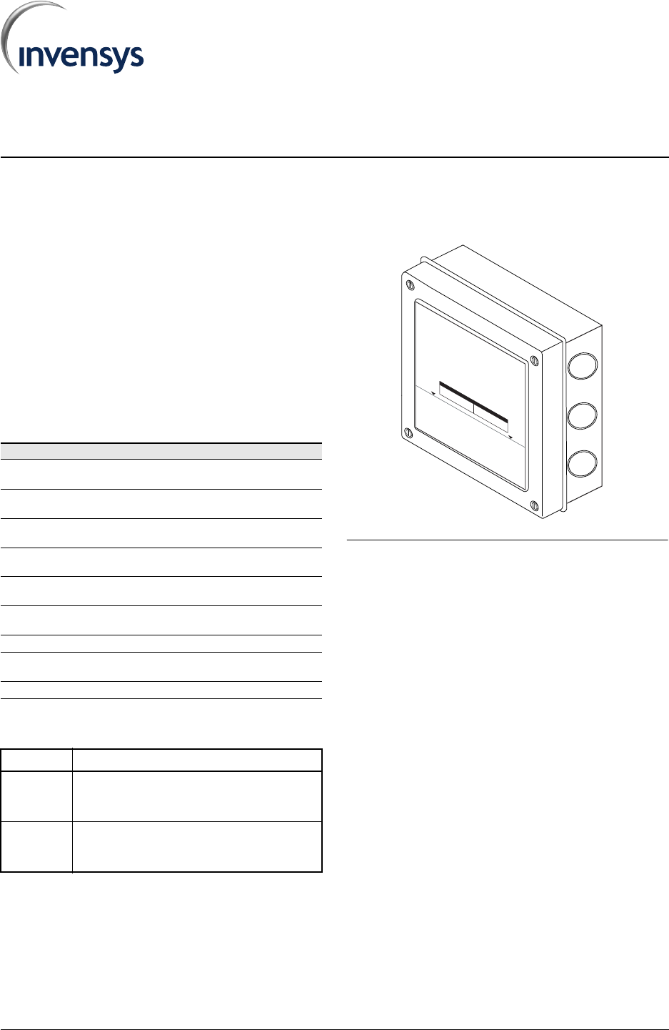
Description
The Invensys RF Load Control Meter (LCM) is a
remote switching device that receives load control
OFF and ON commands from the GoodWatts
system. Commands are received via an RF
Communications network.
The LCM is connected in line with the existing
electrical wiring to the appliance, which enables it to
be mounted at any location with easy access to the
existing wiring. The enclosure is watertight, dust
tight, and corrosion resistant, making it suitable for
both indoor and outdoor locations. Mounting holes
are provided at each corner to secure the LCM to a
flat surface.
TABLE 1. Specifications
TABLE 2. Style Chart
FIGURE 1. Invensys RF Load Control Meter
Note: This equipment has been tested and found to
comply with the limits for a Class B digital device,
pursuant to Part 15 of the FCC Rules. These limits are
designed to provide reasonable protection against
harmful interference in a residential installation. This
equipment generates, uses and can radiate radio
frequency energy and, if not installed and used in
accordance with the instructions, may cause harmful
interference to radio communications. However, there is
no guarantee that interference will not occur in a
particular installation. If this equipment does cause
harmful interference to radio or television reception,
which can be determined by turning the equipment off
and on, the user is encouraged to try to correct the
interference by one or more of the following measures:
– Reorient or relocate the receiving antenna.
– Increase the separation between the equipment and
receiver.
– Connect the equipment into an outlet on a circuit
different from that to which the receiver is
connected.
– Consult the dealer or an experienced radio/TV
technician for help.
Item Description
Electrical
input:
vL02606100: 120 VAC rms, 60 Hz., 2-wire
vL02606200: 240 VAC rms, 60 Hz., 2-wire
Contact
rating:
30A @240VAC rms
Wiring
Terminals:
#14 - #10 AWG, copper conductors only, solid
or stranded
Operating
temperature:
-40 to +65 deg. Celsius
Storage
temperature:
-40 to +85 deg. Celsius
Humidity
tolerance:
0 to 100% RH (non-condensing)
Enclosure: NEMA 4x rated
Physical
dimensions:
7.0” x 7.0” x 3.02”
Weight: 2 lbs
Model Style Description
vL02606100
– Controls 120 VAC single-phase loads with
current up to 30A resistive.
– Supports 1 h.p. single phase inductive motor.
vL02606200
– Controls 240 VAC single-phase loads with
current up to 30A resistive.
– Supports 2 h.p. single phase inductive motor.
POWER
COMM. ACTIVE
WHEN FLASHING
CURTAILMENT
INEFFECT
CURTAILMENT
OVERRIDE
Invensys RF Load ControlMe
ter
Model EMSL-200
CAUTI ON-Riskof ElectricS
hock-
Disconnectpower supply before servicing. More thanone disconnect
switch mayberequired to de-energize thee
quipment beforeservicing.
Ratings:240V
AC, 30 AmpsR
esistive, Single Phase
240VAC, 2HP,Single Phase
Do notattach conduit abovet
his line.
FCC ID:QI
2-EMSL-100
This devicecomplieswith Part15of the FCC Rules.
Operationissubject tothe followingtwo conditions:
(1)t
his device maynot cause harmful interference, and
(2) this device must accept any interferencereceived,
including interference that may causeundesired operation.
Raintight enclosure whenmounted witheitherofth
efollowingtw
ofittinginstallations:
Description PartNum
ber
FittingAssy. CD16AA-BK
LockingNut NP-16-BK
O-ringOR-16-BN
Description PartNu
mber
FittingA
ssy.ED16AA-BK
Locking Nut 16-BK
O-ring6
BN
abc

INVENSYS RF LOAD CONTROL METER
2 PRELIMINARY DOCUMENT TD2001
Installation
Caution: This equipment is authorized for use under the United States Federal
Communication Commission Rules and Regulations, Code of Federal Regulations
Chapter 47 part 15 and must be installed in accordance with the instructions provided in
this document. In accordance with FCC requirements, changes or modifications to this
equipment that are not expressly approved by the party responsible for FCC compliance
could void the user's authority to operate this equipment.
Inspection
Inspect the carton for damage. If damaged, notify carrier immediately. Inspect
LCM for damage. Return damaged products.
Requirements
– Installer must be a qualified, experienced technician.
– Job wiring diagrams
–Tools
•Drill bits for panel mounting holes
•Static protection wrist strap
–Mounting screws (4)
General Precautions
Warning: Electrical shock hazard! High voltage is present in the Load Control Meter.
Turn OFF electrical power to the LCM and the electrical appliance prior to installation
or service. Failure to turn off power may result in serious personal injury.
– Follow Static Precautions when installing this equipment.
– Use suitable copper conductors.
– Make all connections according to electrical wiring diagram, national and local
electrical codes.
Static Precautions
Static charges damage electronic components. The microprocessor and
associated circuitry are sensitive to static discharge. Use the following
precautions when installing, servicing, or operating the system.
– Work in a static free area
– Discharge static electricity by touching a known, securely grounded object.
Location
The LCM is connected in line with the existing electrical wiring to the appliance,
which enables it to be mounted at any location with easy access to the existing
wiring. The enclosure is watertight, dust tight, and corrosion resistant, making it
suitable for both indoor and outdoor locations.
– Avoid mounting locations where excessive moisture, corrosive fumes, vibration, or
explosive vapors are present.
– Avoid electrical noise interference. Do not install near large contactors, electrical
machinery, or welding equipment.
– Locate where ambient temperatures do not exceed 150 deg. F (65 deg. C) or fall
below -40 deg. F (-40 deg. C).
MOUNTING
8/6/02 PRELIMINARY DOCUMENT 3
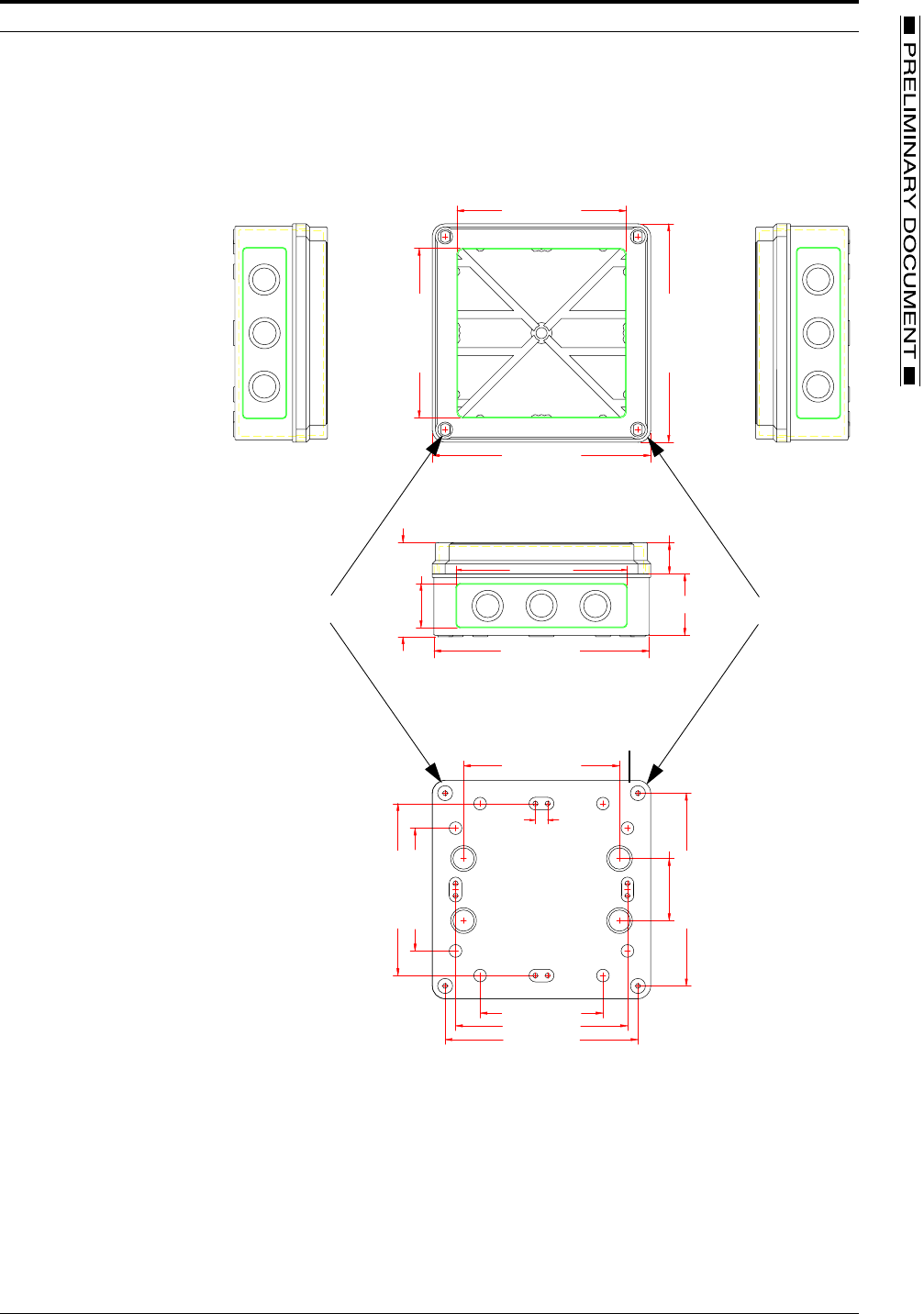
Mounting
Mounting holes are provided at each corner to secure the LCM to a flat surface. Figure 4
shows mounting dimensions. Refer to FIGURE 9. Mounting Template, on page 8 for an
installation template at actual size.
FIGURE 2. Enclosure dimensions
1. Select a flat mounting location.
2. Mark and prepare the surface mounting holes, using dimensions above or use the
template in FIGURE 9. Mounting Template, on page 8.
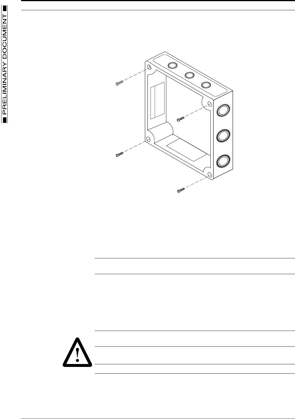
3. Remove the cover from the LCM enclosure by removing the four cover attaching
screws in the corners of the cover.
4. Insert mounting screws down through the same holes that the cover screws came
out of and securely fasten the LCM enclosure to the flat surface.
6.90 [175.36]
7.00 [177.83]
5.43 [138.03]
5.50 [139.58]
3.94 [100.00]
6.18 [157.01]
1.42 [36.09]
1.00 [25.40]
3.94 [100.00]
1.99 [50.50]
6.18 [157.03]
5.51 [140.00]
5.00 [127.00]
END VIEW
REAR VIEW
0.39 [10.00]
5.51 [140.00]
5.43 [138.03]
7.00 [177.83]
1.97 [50.00]
3.02 [76.62]
MOUNTING HOLES
MOUNTING HOLES
NOTE:
DIMENSIONS ARE IN INCHES (MILLIMETERS)
INVENSYS RF LOAD CONTROL METER
4 PRELIMINARY DOCUMENT TD2001
FIGURE 3. Mounting screw location
5. Refer to Wiring, on page 4 and wire the LCM.
6. After wiring is complete, replace the cover and tighten it securely with the four cover
screws.
7. Reapply power to the LCM and the electrical appliance.
Wiring
Caution: It is important to select cable that complies with the NEC code for the
electrical appliance being wired.
The EMSL-100 can control 120 VAC single-phase loads with current ratings up to 30A
resistive. The EMSL-200 can control 240 VAC single-phase loads with current ratings up
to 30A resistive. The LCM is connected in-line with the existing electrical wiring to the
appliance. Multiple-size knockouts are provided around the exterior perimeter of the
housing to accommodate a conduit connector or a cable clamp. Refer to the wiring
chart in Table 3 for terminal listings for both LCM models. Refer also to the example
wiring diagrams in Figure 5 through Figure 8.
Warning: You must turn off AC power to the electrical appliance that you are wiring.
Failure to turn off power could result in physical injury or death.
1. Shut off AC power to the electrical appliance being wired.
Caution: Use only NEMA 4x rated fittings in order to maintain the NEMA 4x rating.
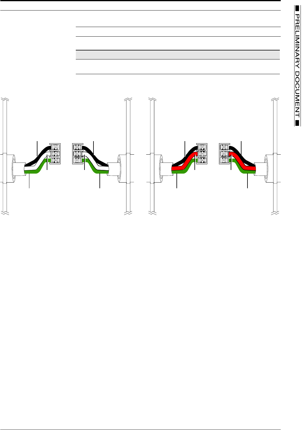
2. Connect the wires for the input (from the AC source) and output (to the electrical
appliance) as shown in Table 3 and in Figure 4. Refer to Figure 4 to see typical wiring
for a 120 VAC and a 240 VAC system.
WIRING
8/6/02 PRELIMINARY DOCUMENT 5
Note: In four-wire 240 VAC configuration, the neutral wire is not connected to the LCM.
TABLE 3. Wiring Chart
FIGURE 4. Installation wiring connections for a 120 and 240 VAC application
3. When wiring is complete reinstall cover (see Mounting on page 3) and apply power
to the LCM and the electrical appliance.
LCM Style Bottom Terminal Center Terminal Top Terminal
vL02606100 Ground (green) Neutral (white) Hot (black)
vL02606200 Ground (green or bare) L2 (red) L1 (black)
L1
L1
240 VAC
L2/N L2/N
EARTH EARTH
L1
L1
120 VAC
L2/N L2/N
EARTH EARTH
GROUND
NEUTRAL
HOT BLACK
WHITE
GREEN GROUND
LINE 2
LINE 1 BLACK
RED
GREEN OR BARE
120 VAC SYSTEM WIRING 240 VAC SYSTEM WIRING
INVENSYS RF LOAD CONTROL METER
6 PRELIMINARY DOCUMENT TD2001
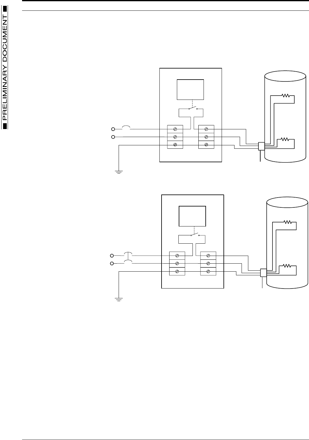
Sample Wiring Schematics
The following schematics provide examples of wiring for hot water heaters and pool
pumps for both 120 VAC and 240 VAC applications.
FIGURE 5. Example wiring for 120 VAC water heater application
FIGURE 6. Example wiring for 240 VAC water heater application
NEUTRAL
LINE 1
GROUND
LOAD CONTROL METER
120 VOLT AC WATER HEATER
30 AMPS MAX
120
VOLTS
CIRCUIT
BREAKER
MEASUREMENT
AND
CONTROL
ELECTRONICS
EXISTING
WATER HEATER
THERMOSTAT
LINE 2
LINE 1
GROUND
LOAD CONTROL METER
CIRCUIT
BREAKER
240 VOLT AC WATER HEATER
30 AMPS MAX
240
VOLTS
MEASUREMENT
AND
CONTROL
ELECTRONICS
EXISTING
WATER HEATER
THERMOSTAT
WIRING
8/6/02 PRELIMINARY DOCUMENT 7
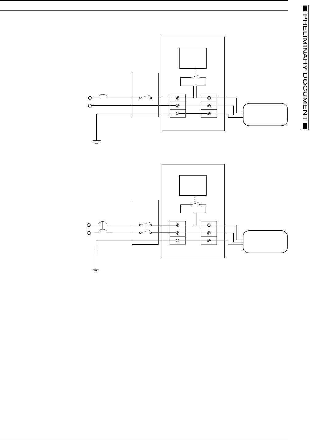
FIGURE 7. Example wiring for 120 VAC pool pump application
FIGURE 8. Example wiring for 240 VAC pool pump application
NEUTRAL
LINE 1
GROUND
CIRCUIT
EXISTING
CIRCUIT
DISCONNECT
BREAKER
120
VOLTS
LOAD CONTROL METER
MEASUREMENT
AND
CONTROL
ELECTRONICS
120 VOLT AC POOL PUMP
1HPMAX
LINE 2
LINE 1
GROUND
LOAD CONTROL METER
MEASUREMENT
AND
CONTROL
ELECTRONICS
CIRCUIT
EXISTING
CIRCUIT
DISCONNECT
BREAKER
240
VOLTS
240 VOLT AC POOL PUMP
2HPMAX
INVENSYS RF LOAD CONTROL METER
8 PRELIMINARY DOCUMENT TD2001
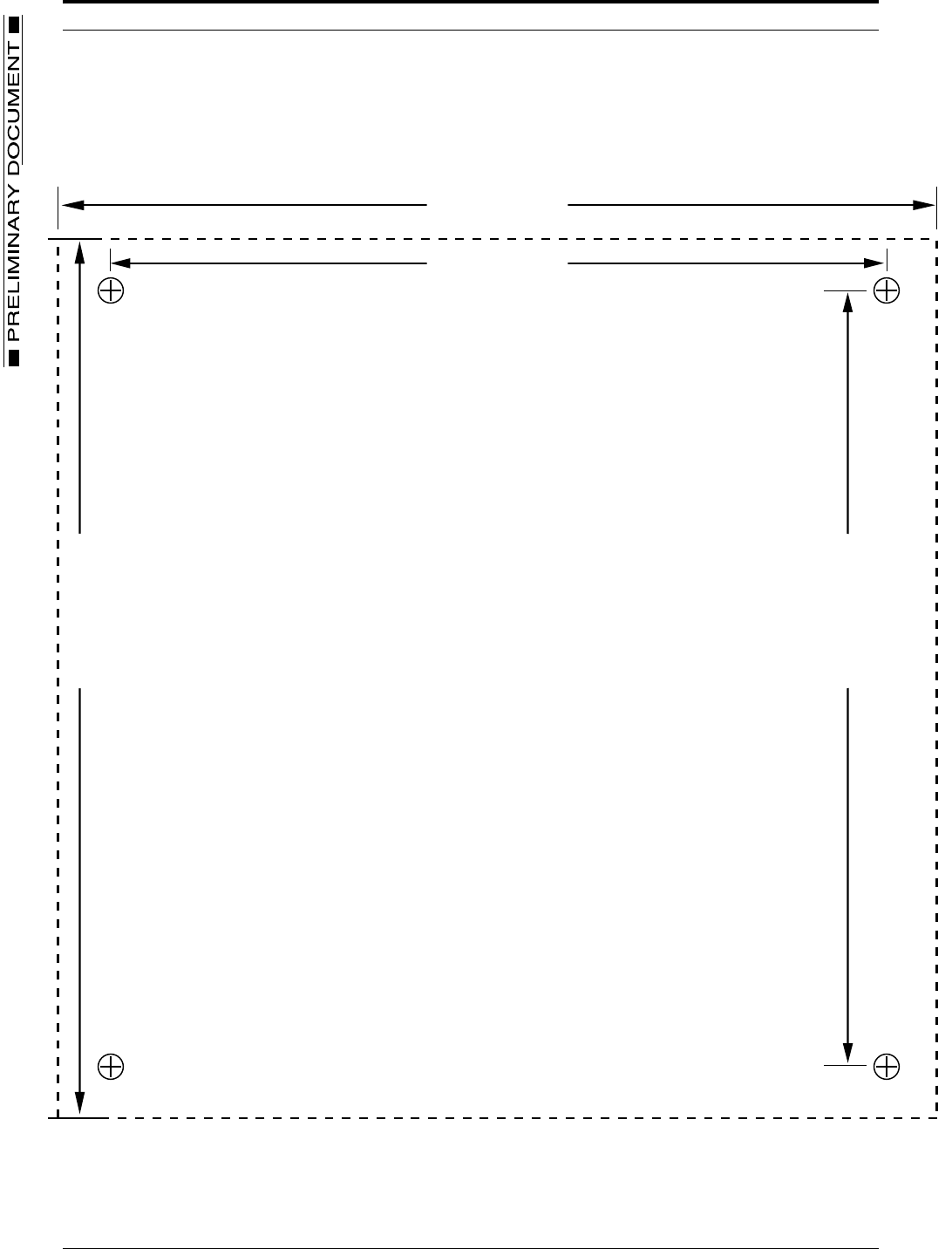
Mounting Template
Note: To ensure accuracy, this template must be printed at 100% actual size.
FIGURE 9. Mounting Template
6.18 (157.01)
7.00 (177.83)
7.00 (177.83)
6.18 (157.01)
ALL DIMENSIONS SHOWN = INCHES (MILLIMETERS)
MOUNTING TEMPLATE
8/6/02 PRELIMINARY DOCUMENT 9
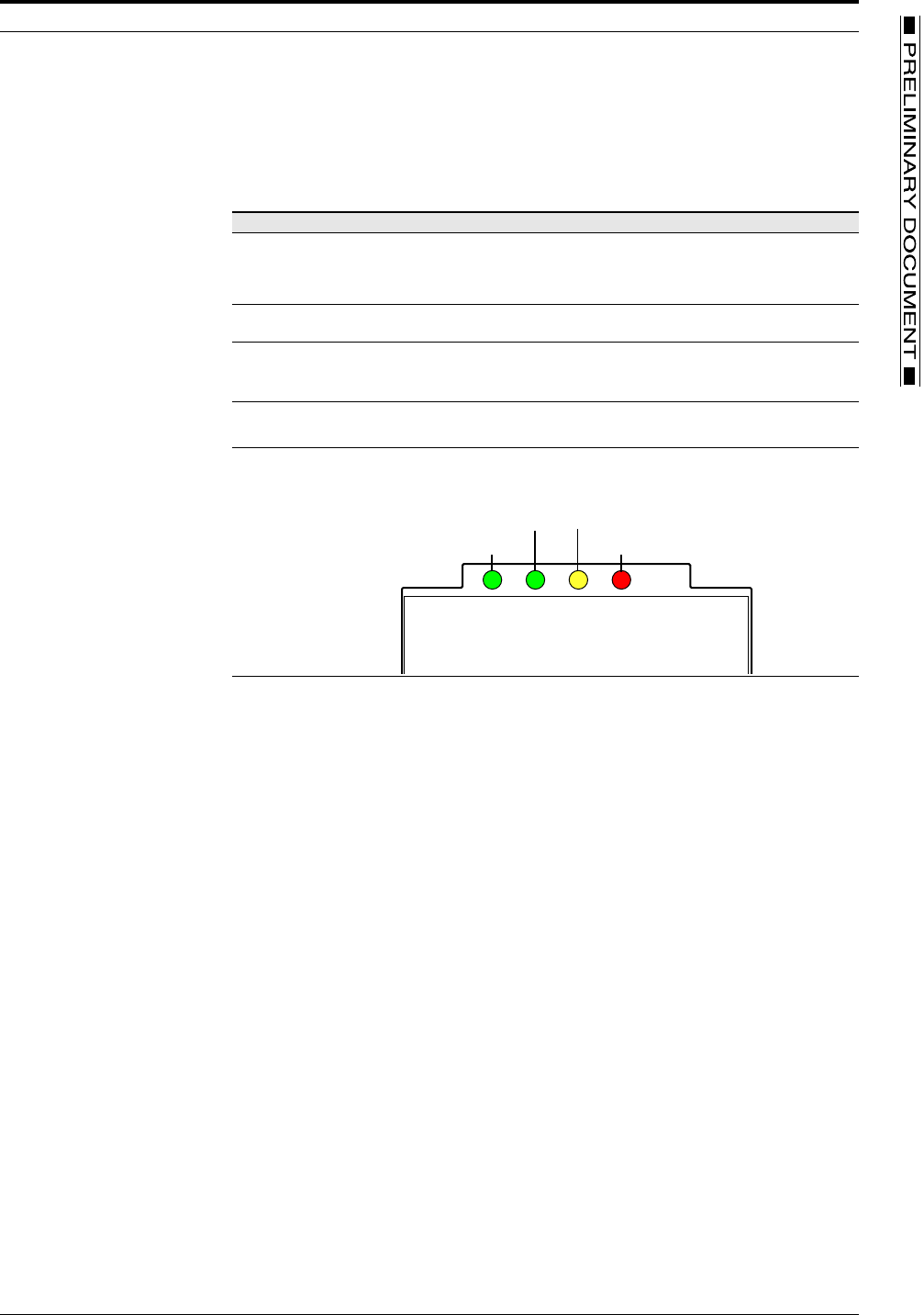
LCM Operations
The only visible controls or indicators on the Invensys RF Load Control Meter
are the four surface mount LED’s. These indicators are listed in described in
TABLE 4. LED indicator descriptions, below.
TABLE 4. LED indicator descriptions
LED Label Color Description
Power Green The green power light illuminates continuously when the following
two conditions are met:
– Power is applied to the LCM
– The LCM is active (processor up)
Comm. Active
when Flashing
Green The green communications active light is firmware controlled and
blinks to indicate activity in the RF communications subsystem.
Curtailment in
Effect
Amber The amber curtailment light illuminates to indicate that a
curtailment is in effect. The LED is OFF when no curtailment is in
effect. Curtailments may be initiated by the appropriate power
provider in accordance with a particular GoodWatts program.
Curtailment
Override
Red The red override light illuminates when the Criminate Override
switch has been set to the ON position. The light is OFF when
Curtailment Override switch is set to the OFF position.
POWER
CURTAILMENT IN EFFECT
OVERRIDE CURTAILEMENT
COMM. ACTIVE WHEN FLASHING
LED LOCATIONS
GREEN GREEN AMBER RED

TD2001 INVENSYS RF LOAD CONTROL METER PRINTED IN U.S.A.
© Invensys 2002
All specifications are nominal and may change as design improvements are introduced. Invensys shall not be liable for damages resulting from mis-
application or misuse of its products.
Marks bearing ® and/or ™ are registered trademarks and trademarks of Invensys.
Terms and product names in this document may be trademarks of others.