Robertshaw Controls TX0669-0200 Centeron Radar Monitor User Manual GWR Manual3
Robertshaw Controls Company Centeron Radar Monitor GWR Manual3
Contents
- 1. Users manual
- 2. Page uncluding RF Exposure statement
Users manual
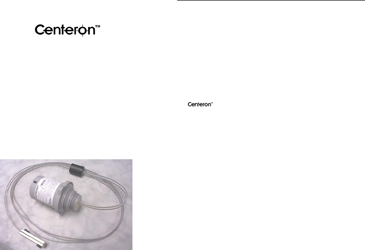
Guided Wave Radar Monitor
Instruction Manual
Model: RM Series
Document # ***********
Revision # 3
Dated 05/07/2002
CenteronTM Guided Wave Radar Monitor Instruction Manual
Notice
The information contained in this document is current as of the date of publication but is
subject to change without notice. Robertshaw makes no warranty, expressed or implied,
with regard to this material, including but not limited to the implied warranties of
merchantability and fitness for a particular purpose. Robertshaw shall not be liable for
errors contained herein or for incidental or consequential damages in connection with the
furnishing, performance, or use of this material.
Robertshaw assumes no responsibility for the use or reliability of its products or
equipment other than that for which it is intended or for use other than in the manner
prescribed herein.
This document is protected by copyright. All rights reserved. No part of this document
may be reproduced, copied, photographed, electronically scanned, or translated into
another language without the prior written consent of Robertshaw.
The logo is a trademark of Robertshaw Controls. Other manufacturer or
service names mentioned in this publication are trademarks, service marks, or registered
trademarks of their respective holders.
2002 Robertshaw Controls. All Rights Reserved.

CenteronTM Guided Wave Radar Monitor Instruction Manual
Robertshaw Industrial Products Page i
05/07/2002
Table of Contents
1.0 Introduction...............................................................................................................1
2.0 Product Overview .....................................................................................................1
2.1 DESCRIPTION ...................................................................................................... 1
2.2 OPERATION......................................................................................................... 1
2.3 ENVIRONMENTAL SPECIFICATIONS ..................................................................... 2
2.4 CERTIFICATIONS ................................................................................................. 2
2.4.1 FCC Notice—Radio Frequency Communications.........................................2
2.4.2 Safety and Regulatory ...................................................................................3
3.0 Installation ...............................................................................................................3
3.1 RF SITE GUIDELINES .......................................................................................... 3
3.2 HANDLING GUIDELINES ...................................................................................... 4
3.3 MOUNTING.......................................................................................................... 5
3.4 ACTIVATION ....................................................................................................... 6
3.5 SITE SURVEY ...................................................................................................... 7
4.0 Troubleshooting and Testing ...................................................................................7
4.1 TROUBLESHOOTING ............................................................................................ 7
4.2 MONITOR TEST ................................................................................................... 9
5.0 Servicing...................................................................................................................10
5.1 BATTERY REPLACEMENT.................................................................................. 10
5.2 WARRANTY ...................................................................................................... 12
5.3 UNIT DISPOSAL................................................................................................. 12
5.4 SERVICE PARTS LIST......................................................................................... 13
5.5 SERVICE AND TECHNICAL SUPPORT.................................................................. 13
Appendix A: Monitoring System .................................................................................A1
Appendix B: Product Drawing ....................................................................................B1
Appendix C: Site Survey Form....................................................................................C1

CenteronTM Guided Wave Radar Monitor Instruction Manual
Robertshaw Industrial Products Page 1
05/07/2002
1.0 Introduction
This manual describes how to install, test, and service the Centeron Flexible Probe
Guided Wave Radar Level Monitor. The Centeron Radar Monitor is part of the
Centeron Level Monitoring System that includes the Data Collection System and
Controller(s).
This guide does not describe how to install, test, maintain or troubleshoot the Centeron
Controller or Data Collection System. Refer to these products’ respective instruction
manuals.
The description herein is based on a standard installation.
2.0 Product Overview
2.1 Description
The CenteronTM Radar Monitor is a member of Robertshaw’s Spread Spectrum Radio
Frequency (RF) family of products. This Monitor detects level, temperature within the
Monitor housing, battery condition, and error codes and broadcasts this information to the
system’s Controller.
The Monitor is calibrated and pre-programmed at the factory with the Serial Number,
Property Code, and Transmission Frequency. No field programming of the Monitor is
required.
2.2 Operation
The Radar Monitor consists of a sealed Polypropylene housing with external pipe threads
which installs in a 1 ½” or 2” National Pipe Thread (NPT) bung. The housing protects
the Monitor’s electronic circuitry and supports the long flexible probe that extends down
into the tank. The Radar Monitor measures liquid level by detecting the vertical position
of a float that rides on the probe at the top of the liquid. The Monitor’s electronic
circuitry measures the time that it takes for an electromagnetic pulse to travel to the float
and back to the Monitor. Travel time for the electromagnetic pulse is proportional to
distance, allowing the Monitor to calculate fluid level. This level information is
transmitted to the Controller using a spread spectrum radio signal in the 902–928 MHz
ISM band. Level information transmitted by the Monitor is in tenths of an inch measured
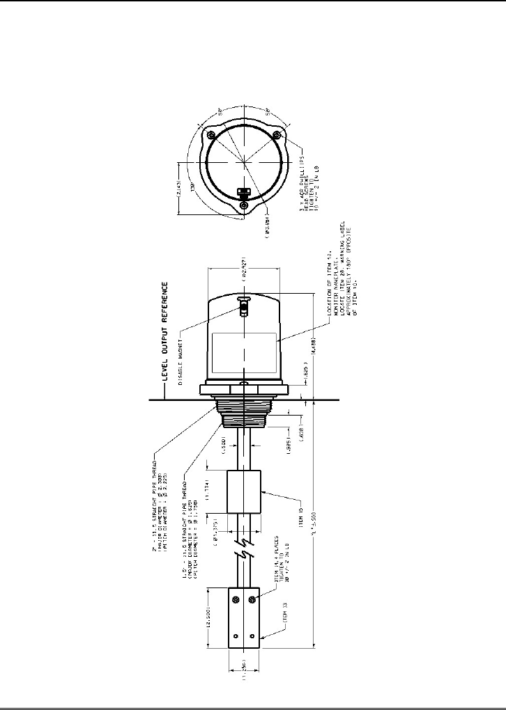
from the level output reference line on the Monitor lower housing (see Figure 3) to the
surface of the fluid.
CenteronTM Guided Wave Radar Monitor Instruction Manual
Robertshaw Industrial Products Page 2
05/07/2002
The Monitor is powered by a replaceable 3-Volt battery that is designed to provide at
least two (2) years life in normal service. However, Monitors that are programmed to
transmit more frequently than once every four hours and Monitors that are subjected to
prolonged exposure to extreme temperatures will exhibit reduced battery life.
2.3 Environmental Specifications
The following environmental specifications should be observed when installing the
Monitor:
• Operating Temperature Range: -40oC to +80oC (-40°F to +176°F)
• The Monitor housing is designed to meet or exceed NEMA 3.
• UV life: 10 years exposure to direct sunlight.
• Shock: The unit will withstand a one-meter drop test per UL 913.
• Chemical Exposure: The Centeron™ Radar Monitor is designed for use in water,
ethylene glycol, oil, and common hydrocarbon fuels such as gasoline, gasoline /
ethanol blends, fuel oil, and diesel fuel. Wetted materials in this design include
polypropylene, 304 and 316 series stainless steel, Nitrile rubber, and FEP Teflon.
For applications involving fluids other than those noted above contact the
Robertshaw Industrial Products Technical Support Group (refer to Section 5.5)
before installation.
• Pressure: The Centeron™ Radar Monitor is designed for use on vented storage tanks
only. The maximum pressure inside the tank must not exceed 3 PSI. A special
adapter (sold separately) is required for use in pressurized applications up to 50 PSI.
2.4 Certifications
2.4.1 FCC Notice—Radio Frequency Communications
The Monitor generates and uses radio frequency energy. If not installed and used in
accordance with the manufacturer’s instructions, it may cause interference to radio and
television reception. The Monitor complies with the specifications in Part 15 of the FCC
Rules for Class B Computing Devices.
CAUTION: Robertshaw Industrial Products Division does not support field changes or
modifications to any of the Centeron™ Level Monitoring System equipment unless they
are specifically covered in this manual. All adjustments must be made at the factory
under the specific guidelines set forth in our manufacturing processes. Any modification
to the equipment will void the manufacturer’s warranty and could void the user’s
authority to operate the equipment and render the equipment in violation of FCC Part 15,
Subpart C, 15.247.
This device complies with Part 15 of the FCC Rules. Operation is subject to the
following two conditions: (1) this device may not cause harmful interference, and (2)

CenteronTM Guided Wave Radar Monitor Instruction Manual
Robertshaw Industrial Products Page 3
05/07/2002
this device must accept any interference received, including interference that may cause
undesired operation.
2.4.2 Safety and Regulatory
The Monitor is designed to comply with UL Standards for Intrinsically Safe Apparatus
for use in Class I, Division 1, Group D locations. The Monitor conforms to UL 913 and
has been certified to CAN/CSA Standard C22.2 No. 157 and Standard C22.2 No. 94.
WARNING: SUBSTITUTION OF COMPONENTS MAY IMPAIR INTRINSIC
SAFETY.
AVERTISSEMENT: LA SUBSTITUTION DE COMPOSANTS PEUT
COMPROMETTRE LA SÉCURITÉ INTRINSÈQUE.
3.0 Installation
A Quick Installation Guide, which provides an overview of the Radar Monitor
installation procedure, was included with this product.
The following sections of this manual explain in detail the site selection and installation
process:
3.1 Radio Installation Guidelines
The Centeron™ Radar Monitor contains sensitive measurement circuitry and a radio
transmitter. Large metal objects such as buildings and vehicles may affect the
transmission of radio signals. Electrical equipment may produce electronic noise that
could adversely affect signal quality.
Direct line of sight between the Centeron™ Monitor and Controller will provide
optimum radio reception.
The Centeron™ Monitor and Controller can communicate at distances up to one mile
under optimum line-of-sight conditions.
When obstructions such as walls, buildings, and vehicles exist between the
Centeron™ Monitor and Controller the distance between these units should be
limited to less than 500 feet.
Multiple obstructions (such as two or more walls or a tank and a wall) between the
Monitor and Controller should be avoided, if possible.
CenteronTM Guided Wave Radar Monitor Instruction Manual
Robertshaw Industrial Products Page 4
05/07/2002
Electrically conductive objects such as metal buildings, concrete reinforcement rods,
tanks, silos, and vehicles reflect radio signals. This reflection can be either an
advantage or disadvantage to good radio reception at a particular installation site:
1. Metal objects between the Monitor and Controller may reflect and scatter
RF energy and reduce radio signal strength at the Controller.
2. Metal objects behind the Monitor or Controller may increase the radio
signal strength at the Controller by reflecting radio signals toward the
Controller.
Even small metal objects such as tank vents or toolboxes between the Monitor and
Controller can significantly reduce radio signal strength if they are within a few feet
of the Monitor or Controller. These objects can reflect radio signals and cause a RF
“shadow” which may prevent radio signals from reaching the Controller.
Objects which are not electrically conductive such as wooden or fiberglass buildings,
non-reinforced masonry, trees, plastic, and glass have less effect on radio signals
than metal objects.
Windows and wooden doors can provide radio signals access into otherwise closed
metal buildings. However, “low-E” window glass may have a thin metallic coating
that can reflect radio signals.
Strong electromagnetic fields such as those found in close proximity to power lines,
large electric motors, generators, electric fences, and transmitter antennas may
interfere with the radio signals received by the Centeron™ Controller.
The Centeron™ Controller should be mounted as high as is reasonably possible to
improve its ability to receive radio signals. For example, placing the Controller on a
high shelf would be preferable to setting the unit on a floor near ground level.
Installing the Controller on the second floor of a two-story structure would be more
desirable than installing it on the ground floor. Installing the Controller in an
underground basement should be avoided.
Warning: For maximum Monitor reception, mount the Monitor within 500 feet of
the Controller, avoid mounting Monitor inside a fully closed metal building, and
avoid close proximity to large electrical equipment. Do not paint the Centeron™
Monitor or Controller housings.
3.2 Handling Guidelines
The Centeron™ Radar Monitor is designed to provide many years of reliable service in
demanding outdoor environments. However, the Monitor contains sensitive

CenteronTM Guided Wave Radar Monitor Instruction Manual
Robertshaw Industrial Products Page 5
05/07/2002
measurement circuitry and should be handled carefully. Do not throw or drop the
Monitor. Do not pull on the probe cable. Do not kink or twist the probe cable. Do not
attempt to disassemble the Monitor except as described in section 5.1 (Battery
Replacement).
When removing the Monitor for storage or shipment insert the disable magnet securely in
the magnet slot. Clean the probe, float, and anchor with a damp cloth. Secure the probe
cable in a flat coil and pack the Monitor in a protective container.
3.3 Mounting
After the Controller has been successfully setup, the Monitor can be mounted to the tank
by following these instructions:
Warning: If the tank contains flammable liquid or vapor, extinguish all flames and
smoking material before performing the Monitor installation procedure.
• Remove the Monitor from its protective packaging. Along with the Monitor, there
will be two O-rings in the package, one 1.5” and the other 2” in diameter.
• Select a permanent mounting location on the top of the tank that will allow the Radar
Monitor cable to hang vertically inside the tank. Verify that there is adequate
clearance to prevent the float, cable, or anchor from contacting obstructions such as
walls, baffles, reinforcements, and other measurement equipment inside the tank.
There should be at least two inches of clearance between the probe cable and any
obstructions. Remove all materials from the desired bung.
• The Monitor may be installed in a standpipe if necessary. However, the standpipe
should be have an inside diameter of at least two inches and its length should be
minimized. Verify that the standpipe is vertical and that the probe cable and float
will not contact the sides of the pipe.
• Measure from the top of the tank opening where the monitor will be mounted to the
inside bottom surface of the tank. Verify that the cable anchor will not touch the
bottom of the tank when the Monitor is installed. If necessary, loosen the four cable
anchor screws and carefully slide the anchor up the cable so that it will be positioned
approximately two inches above the inside bottom surface of the tank. Tighten the
cable anchor screws to approximately 10 in. lb torque and cut off any excess cable
flush with the bottom of the anchor.
• Determine the appropriate mounting O-ring to use based on the size of the tank
opening. Slip the O-ring over the probe end of the Monitor and slide it past the lip at
the base of the lower housing threads. Press along the O-ring circumference until it
is snug.
• Lower the anchor, probe, and float into the tank while being extremely careful not to
nick the cable insulation on the tank threads. Verify that no twists or kinks are
allowed to remain in the cable. Imperfections in the cable such as these must be
straightened by hand as the cable is lowered into the tank.
CenteronTM Guided Wave Radar Monitor Instruction Manual
Robertshaw Industrial Products Page 6
05/07/2002
• Carefully screw the Monitor into the tank opening by hand tightening it 1/8 turn
clockwise past engaging the O-ring. Assembly requires only a snug fit. Do not
over-tighten.
• When installation is complete the probe cable should hang straight and vertical in the
tank. The float should rest on the liquid surface and move freely on the cable.
Note: For maximum Monitor performance, adjust the tank so that the top mounting
surface of the tank opening is level to within +/- 5 degrees. A bubble level may be
used for this task.
Repeat these steps for additional Monitors.
Warning: For maximum Monitor reception, mount the Monitor within 500 feet of the
Controller, avoid mounting the Monitor or Controller inside a fully closed metal building
or in a metal enclosure, and avoid close proximity to large electrical equipment. Do not
paint the Centeron™ Monitor or Controller housings.
3.4 Activation
After Monitor mounting, follow these steps to activate the unit(s):
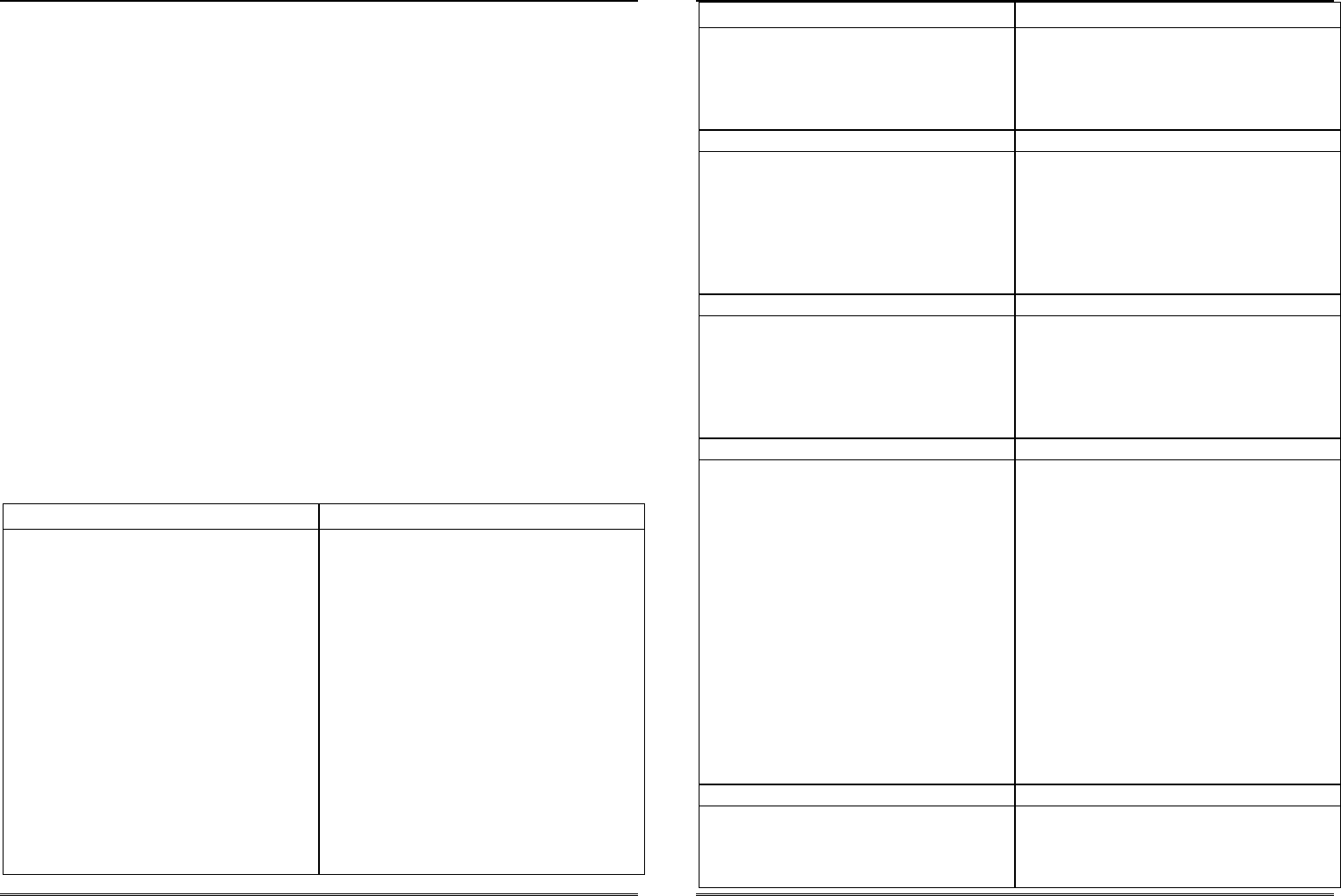
• To activate the Monitor, pull the disable magnet completely out of the top of the
Monitor housing (see figure 3). This will activate the Monitor to make
measurements and burst transmissions on a factory-programmed interval.
Note: Do not discard the magnet completely—keep it accessible for future use if
needed. Do not store the magnet in the Monitor upper housing slot since this will
de-activate the Monitor.
• When the disable magnet is removed from the upper housing slot the Monitor will
immediately make a level measurement and transmit this information. The Monitor
then waits for three minutes and then makes transmissions every thirty seconds for
the next four minutes. The Controller will flicker the green “Test” LED each time it
successfully receives a Monitor transmission. After this initial activation routine the
Monitor reverts to its factory programmed transmission interval.
Note: The installer can verify radio reception at the Controller by watching the
“Test” LED during the Monitor’s activation sequence.
To activate multiple Monitors, repeat these steps.
CenteronTM Guided Wave Radar Monitor Instruction Manual
Robertshaw Industrial Products Page 7
05/07/2002
3.5 Site Survey
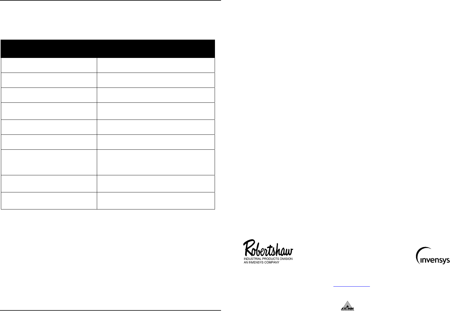
Appendix C contains a Site Survey Form, which should be filled out by the installer.
Record the following information on the Site Survey Form:
• Contact Name
• Contact Address
• Contact Telephone Number
• GPS Location (latitude/longitude)
• Product Name
• Product ID
• Tank Orientation (horizontal/vertical cylinder, oblong, etc.)
• Tank Geometry (diameter, length, width, etc.)
• Tank Contents (diesel fuel, gasoline, etc.)
4.0 Troubleshooting and Testing
This section contains procedures for testing the Centeron™ Radar Monitor and provides
information for troubleshooting the Monitor installation.
4.1 Troubleshooting
If the Monitor is not operating properly, try to locate the solution below:
Question Solution
Has the Monitor ever reported into the
Data Collection System?
If Never:
Verify that the Controller is properly
installed. Refer to the Controller
Instruction Manual for installation
verification.
Perform the Monitor test in Section 4.2
with the Monitor installed. If this test is
unsuccessful, perform the same test with
the Monitor near the Controller installation
location. If successful only at bench
testing, re-evaluate the installation site for
RF interference problems and refer to
Section 5.5 for technical support. If not
successful at either test, continue with
troubleshooting.
CenteronTM Guided Wave Radar Monitor Instruction Manual
Robertshaw Industrial Products Page 8
05/07/2002
Question Solution
Replace the 3 VDC 2/3A LiMnO2 battery
by following Section 5.1 and repeat the
above tests. If still having problems, refer
to Section 5.5 for technical support.
Does the Monitor occasionally miss
scheduled report times
If Yes:
The most likely cause is RF interference
problems. Re-evaluate the installation site
per Section 3.1 for RF interference
problems and refer to Section 5.5 for
technical support.
Does the Monitor ever report a low
battery status?
If Yes:
Replace the 3 VDC 2/3A LiMnO2 battery
by following Section 5.1 and repeat the
above tests. If still having problems, refer
to Section 5.5 for technical support.
Does the Monitor ever report error codes? If Yes, find the error code below:
Code ER00: Indicates an EEPROM
memory failure
Code ER07: Indicates a RAM memory
failure
Code ER10: Indicates that the measured
distance to the liquid surface
exceeds the stored probe
length
Record the code number that is reported
and refer to Section 5.5 for technical
support.
Does the Monitor report significantly
more or less liquid than is actually present
in the tank?
If Yes:
Obstructions in the tank such as baffles,
reinforcin
g
rods
,
other level sensors
,
p
i
p
es
,

CenteronTM Guided Wave Radar Monitor Instruction Manual
Robertshaw Industrial Products Page 9
05/07/2002
Question Solution
etc. can cause the Monitor to report a false
level. Obstructions can cause the float to
become stuck or can cause erroneous radar
reflections. Verify that the float is freely
riding on the liquid surface and that the
probe cable is clean, straight, and not
touching any objects in the tank. If
necessary, carefully clean the cable with a
damp rag and straighten any kinks or twists
in the cable.
Warning: Do not pull on the probe cable.
4.2 Monitor Test
The Monitor is designed to wake up, take a measurement, and transmit RF data every
time that it is activated. The Monitor is activated by inserting and then removing the
disable magnet (see figure 3). At the same time that the Monitor transmits its RF data,
the Controller will acknowledge receipt of the transmission by blinking the green “Test”
Light Emitting Diode. If the Controller has never received data from this particular
Monitor (this is the case during initial installation or after the Controller has been reset),
it will then initiate a call to the Data Collection System to report a “new Monitor” and
request configuration data. With this in mind, use the following steps to verify
installation and troubleshoot system communication problems.
1. Reset the Controller by following the guidelines under the Controller test section of
the Controller instruction manual. Proceed to the next step only if this step is
successful.
2. Insert the disable magnet into the slot of the Monitor’s upper housing until snug.
3. Activate the Monitor by completely removing the disable magnet from the upper
housing. The Monitor will immediately make one transmission. Three minutes after
this initial transmission the Monitor will make a series of transmissions (one every
thirty seconds) for the next four minutes.
4. Verify that the Controller successfully receives RF transmissions from the Monitor
by watching the green “Test” LED flicker.
5. Verify that the Controller initiates a phone call and returns to ready mode (see
Controller Instruction Manual on how to recognize Ready mode).
CenteronTM Guided Wave Radar Monitor Instruction Manual
Robertshaw Industrial Products Page 10
05/07/2002
Repeat the above test as necessary, using the guidance of Section 4.0 to determine the
cause of communication problems.
5.0 Servicing
5.1 Battery Replacement
If it becomes necessary to replace the battery in the Monitor, follow these steps:
WARNING: TO PREVENT IGNITION OF A HAZARDOUS ATMOSPHERE, THE
BATTERY MUST ONLY BE CHANGED IN AN AREA KNOWN TO BE
NONHAZARDOUS.
AVERTISSEMENT: AFIN DE PRÉVENIR L’INFLAMMATION D’ATMOSPHÈRES
DANGEREUSES, NE CHANGER LE BATTERIE QUE DANS DES
EMPLACEMENTS DÉSIGNÉS NON-DANGEREUX.
Caution: When performing this procedure be extremely careful not to disturb the two
wires that connect the probe to the circuit board.
Warning: Use Duracell Ultra DL123A Lithium Manganese Dioxide 3 volt battery only.
Warning: If the tank contains flammable liquid or vapor, extinguish all flames and
smoking material before performing the battery replacement procedure.
1. Carefully remove Monitor from the tank by reversing the mounting procedure (see
section 3.3 of this manual). Transport the monitor out of the hazardous area before
proceeding with the battery replacement procedure.
2. Ground yourself by either wearing an anti-static wrist strap or by touching a
grounded metal object (such as a copper water pipe).
3. Remove the Monitor’s upper housing by removing the 3 Phillips head screws and
carefully lifting the upper housing off of the lower housing.
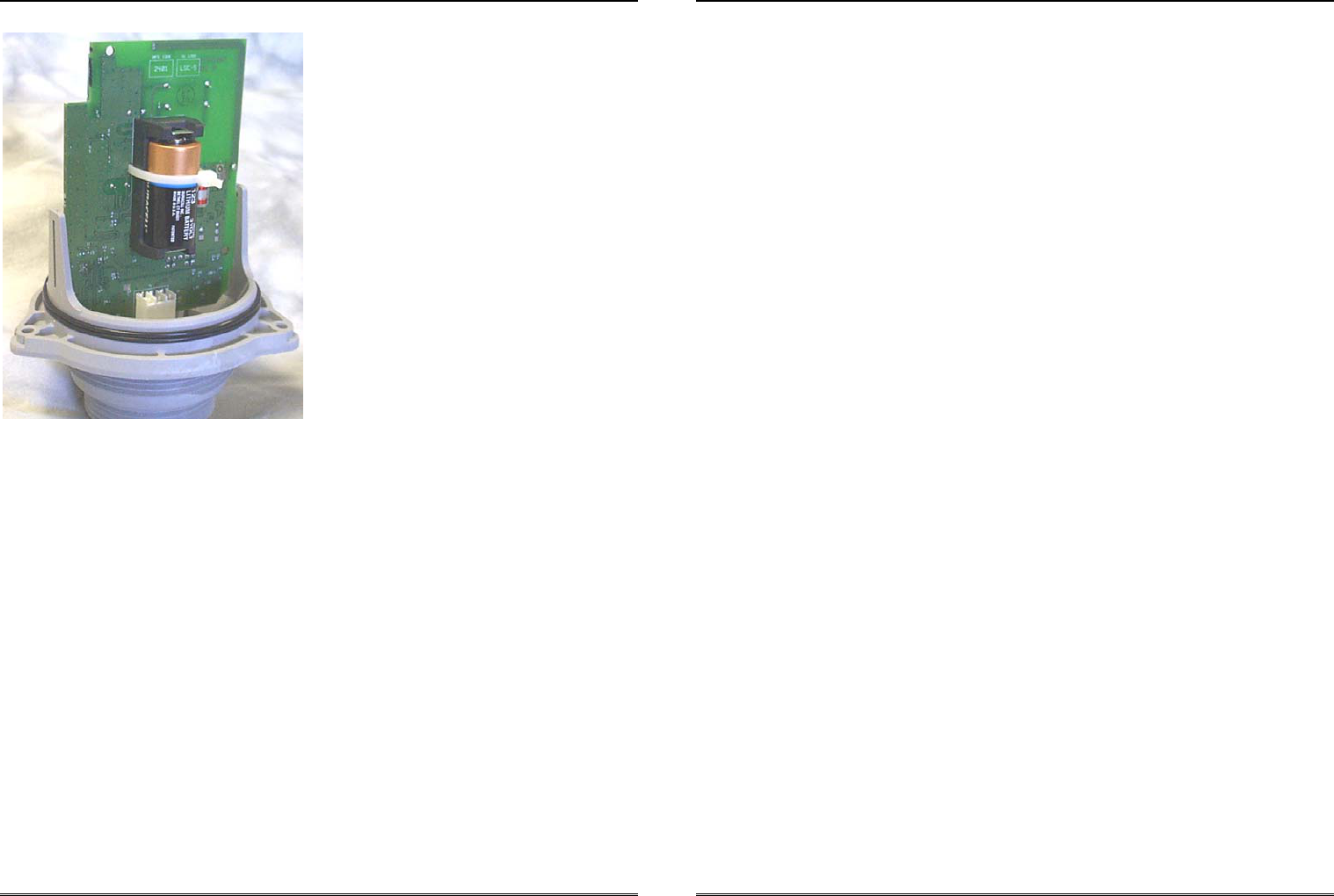
4. Cut and discard the wire tie that secures the old battery (see Figure 1).
CenteronTM Guided Wave Radar Monitor Instruction Manual
Robertshaw Industrial Products Page 11
05/07/2002
Figure 1. Radar Monitor without Cover (Replacing the Battery)
5. Remove the old battery.
6. Insert the new battery (observing polarity markings molded into the battery holder).
7. Carefully install a new wire tie through the circuit board slots and secure it around
the battery. Trim the free end of the wire tie leaving at least ¼” of un-trimmed
material.
8. Ensure that both upper housing O-rings are properly positioned on the lower housing
O-ring shelf (see Figure 1).
9. Firmly reinstall the Monitor’s upper housing.
Note: The mounting screws are not evenly spaced around the upper housing in
order to insure that the housing will only fit in the proper orientation.
10. Using a Phillips screwdriver, gently tighten the 3 screws on the Monitor housing to
10+/- 2 inch pounds. Do not over-tighten.
11. Re-install the Monitor on the tank (refer to section 3.3 of this manual).
12. Follow the battery manufacturers’ safety and disposal guidelines.
CenteronTM Guided Wave Radar Monitor Instruction Manual
Robertshaw Industrial Products Page 12
05/07/2002
5.2 Warranty
Seller warrants title and that products sold to Buyer shall be free from defects in material
and workmanship and shall conform to specifications for a period of one (1) year from
purchase for complete units and parts and subassemblies. Warranties on goods sold but
not manufactured by the seller are expressly limited to the terms of warranties of the
manufacturer of such goods.
Seller makes no representation or warranty of any kind, express or implied, as to
merchantability, fitness for particular purpose or any other matter. Upon receipt of
definite shipping instructions, Buyer shall return, transportation prepaid, all defective
material, or material not conforming to specifications, to Seller, after inspection by Seller,
or at Seller’s election, subject to inspection by Seller. Material returned by Buyer must
be returned in same condition as when received by Buyer. Defective material, or material
not conforming to specifications, so returned shall be replaced or repaired by Seller and
returned, freight prepaid, without any additional charge, or in lieu of such replacement or
repair, Seller, may, at Seller’s option, refund the purchase price applicable to such
material. Seller agrees to pay return freight charges not exceeding the lowest rail or truck
rate which would apply from the original destination on all defective material, or material
not meeting specifications. However, Seller shall not be obligated for such charges when
material returned proves to be free from defect and to meet specifications. Material that
proves to be free from defect and to meet specifications shall be held by Seller for
shipping instructions and Buyer shall furnish such instructions promptly upon request.
Seller’s liability shall be limited solely to the replacement or repair or to refunding the
purchase price applicable to the defective material or material not meeting specifications.
Seller shall not be liable for any consequential damages nor any loss, damages or
expenses directly or indirectly arising from the use of the material.
5.3 Unit Disposal
The plastic parts of the Monitor housing are marked for recycling purposes. An approved
battery recycling center must dispose of the battery.
CenteronTM Guided Wave Radar Monitor Instruction Manual
Robertshaw Industrial Products Page 13
05/07/2002
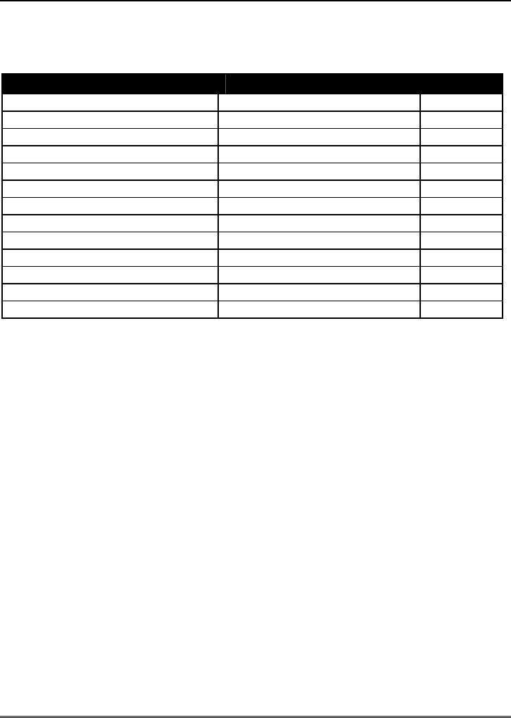
5.4 Service Parts List
Robertshaw Part Number Description Quantity
*********** Instruction Manual 1
*********** Quick Installation Leaflet 1
039912A0001 Upper Housing Screw 3
039911A0001 Battery 1
039898A0001 Wire Tie (To Retain Battery) 1
086607A0001 Disable Magnet Assembly 1
036240N0039 Upper Housing O-ring 1
036240N0229 2” Mounting O-Ring 1
036240N0225 1 ½” Mounting O-Ring 1
*********** Anchor Plate 2
*********** Anchor Screw 4
*********** Float Assembly 1
*********** Pressurized Tank Adapter 1
5.5 Service and Technical Support
For service and technical support, contact Robertshaw Industrial Products Service Center
at (865) 981-3104.
CenteronTM Guided Wave Radar Monitor Instruction Manual
Robertshaw Industrial Products Page A-1
05/07/2002
Appendix A: Monitoring System
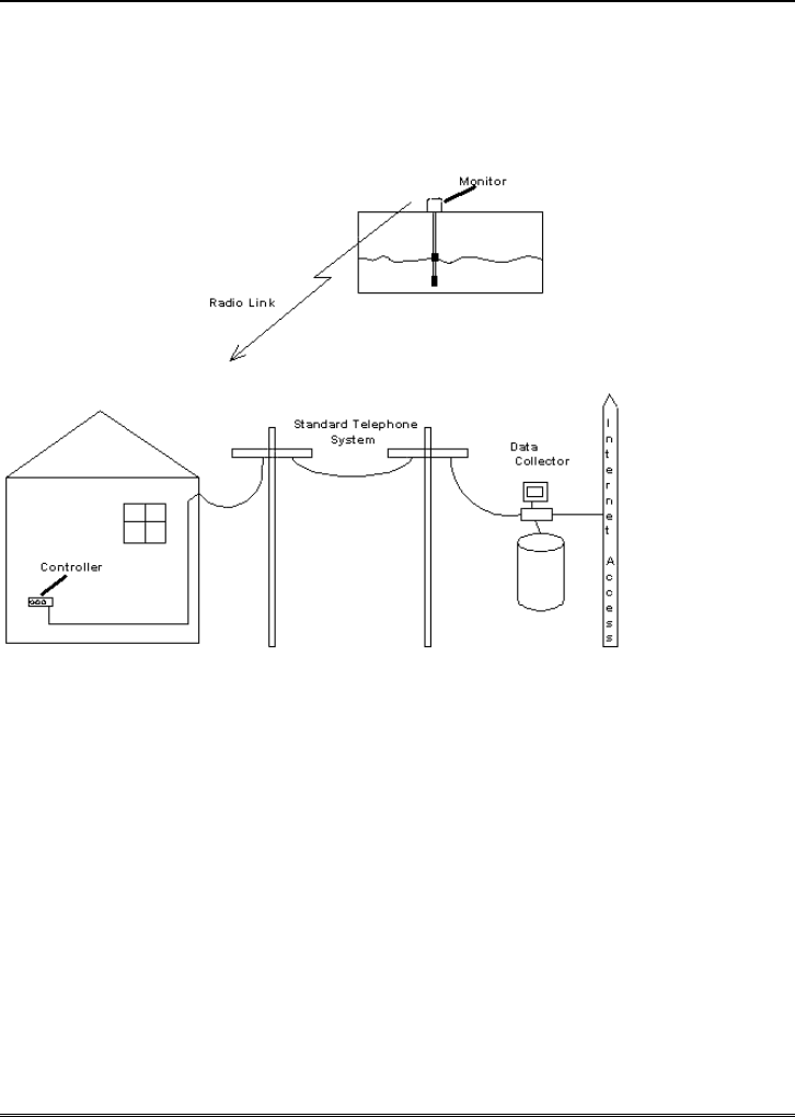
Figure 2. Centeron Level Monitoring System
CenteronTM Guided Wave Radar Monitor Instruction Manual
Robertshaw Industrial Products Page B-1
05/07/2002
Appendix B: Product Drawing
Figure 3. Monitor Drawing
CenteronTM Guided Wave Radar Monitor Instruction Manual
Robertshaw Industrial Products Page C-1
05/07/2002
Appendix C: Site Survey Form
Figure 4. Site Survey Form
Robertshaw Centeron™ Level Monitoring System
Site Survey Form
Contact Name:
Contact Address:
Contact Telephone Number:
GPS Location
(latitude/longitude):
Product Name:
Product ID:
Tank Orientation
(horizontal/vertical cylinder,
oblong, etc.):
Tank Geometry (diameter,
length):
Tank Contents:
U.S.A. – Robertshaw Industrial Products Division, 1602 Mustang Drive, Maryville, Tennessee 37801
865-981-3100 • Fax: 865-981-3168
www.Centeron.net
The product described within contains RF technology licensed through Axonn Corp.
under the following patents: 5,067,136 5,095,493 5,457,713