Roche Diagnostics RWF1 RFID Reader System User Manual Installation Instructions
Roche Diagnostics AG RFID Reader System Installation Instructions
UserManual.wiki
>
Roche Diagnostics
>
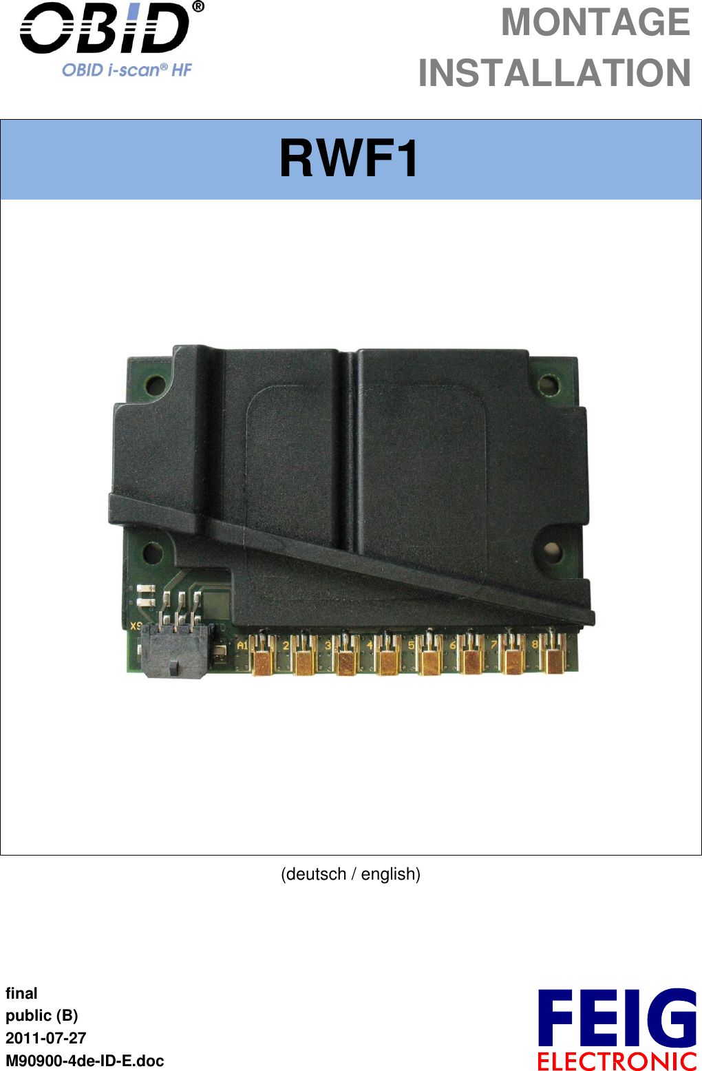
RWF1 User Manual
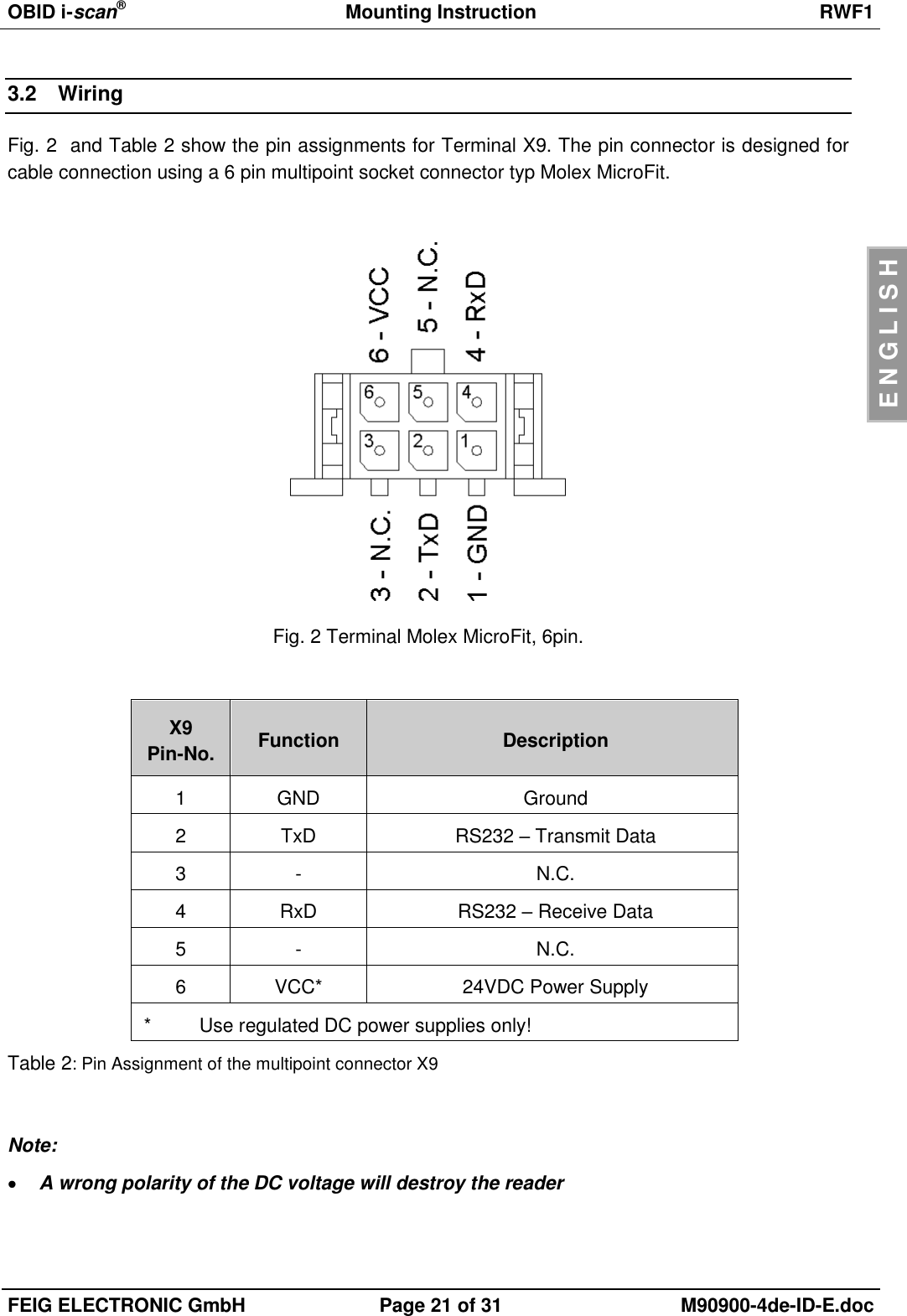
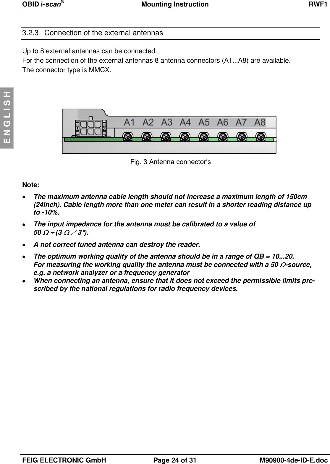
Installation Instructions
Navigation menu
Upload a User Manual
Namespaces
Wiki Guide
HTML
PDF
Info
Views
User Manual
Discussion / Help
Navigation