Roche Diagnostics RWF1 RFID Reader System User Manual Installation Instructions
Roche Diagnostics AG RFID Reader System Installation Instructions
Installation Instructions
MONTAGE
INSTALLATION
final
public (B)
2011-07-27
M90900-4de-ID-E.doc
RWF1
(deutsch / english)


OBID i-scan®
Montage
RWF1
FEIG ELECTRONIC GmbH
Seite 3 von 31
M90900-4de-ID-E.doc
D E U T S C H
Hinweis
Copyright 2010-11 by
FEIG ELECTRONIC GmbH
Lange Straße 4
D-35781 Weilburg-Waldhausen
Tel.: +49 6471 3109-0
http://www.feig.de
Alle früheren Ausgaben verlieren mit dieser Ausgabe ihre Gültigkeit.
Die Angaben in diesem Dokument können ohne vorherige Ankündigung geändert werden.
Weitergabe sowie Vervielfältigung dieses Dokuments, Verwertung und Mitteilung ihres Inhalts sind nicht
gestattet, soweit nicht ausdrücklich zugestanden. Zuwiderhandlung verpflichtet zu Schadenersatz. Alle
Rechte für den Fall der Patenterteilung oder Gebrauchsmuster-Eintragung vorbehalten.
Die Zusammenstellung der Informationen in diesem Dokument erfolgt nach bestem Wissen und Gewissen.
FEIG ELECTRONIC GmbH übernimmt keine Gewährleistung für die Richtigkeit und Vollständigkeit der An-
gaben in diesem Dokument. Insbesondere kann FEIG ELECTRONIC GmbH nicht für Folgeschäden auf
Grund fehlerhafter oder unvollständiger Angaben haftbar gemacht werden. Da sich Fehler, trotz aller Bemü-
hungen nie vollständig vermeiden lassen, sind wir für Hinweise jederzeit dankbar.
Die in diesem Dokument gemachten Installationsempfehlungen gehen von günstigsten Rahmenbedingun-
gen aus. FEIG ELECTRONIC GmbH übernimmt weder Gewähr für die einwandfreie Funktion in system-
fremden Umgebungen, noch für die Funktion eines Gesamtsystems, welches die in diesem Dokument be-
schriebenen Geräte enthält.
FEIG ELECTRONIC weist ausdrücklich darauf hin, dass die in diesem Dokument beschriebenen Geräte
nicht für den Einsatz mit oder in medizinischen Geräten oder für Geräte für lebenserhaltende Maßnahmen
konzipiert sind, bei denen ein Fehler eine Gefahr für menschliches Leben oder für die gesundheitliche Un-
versehrtheit zur Folge haben kann. Der Applikationsdesigner ist dafür verantwortlich geeignete Maßnahmen
zu ergreifen um Gefahren, Schäden oder Verletzungen zu vermeiden.
FEIG ELECTRONIC GmbH übernimmt keine Gewährleistung dafür, dass die in diesem Dokument enthal-
tenden Informationen frei von fremden Schutzrechten sind. FEIG ELECTRONIC GmbH erteilt mit diesem
Dokument keine Lizenzen auf eigene oder fremde Patente oder andere Schutzrechte.
OBID® und OBID i-scan® ist ein eingetragenes Warenzeichen der FEIG ELECTRONIC GmbH
my-d® ist ein eingetragenes Warenzeichen der Infineon Technologies AG
I-CODE® und mifare® ist ein eingetragenes Warenzeichen der Philips Electronics N.V.
Tag-it ist ein Warenzeichen der Texas Instruments Incorporated

OBID i-scan®
Montage
RWF1
FEIG ELECTRONIC GmbH
Seite 4 von 31
M90900-4de-ID-E.doc
D E U T S C H
Inhalt
1 Sicherheits- und Warnhinweise - vor Inbetriebnahme unbedingt lesen 5
2 Leistungsmerkmale des Readermoduls RWF1 6
2.1 Leistungsmerkmale .................................................................................................... 6
2.2 Lieferumfang ............................................................................................................... 6
3 Montage und Anschluss 7
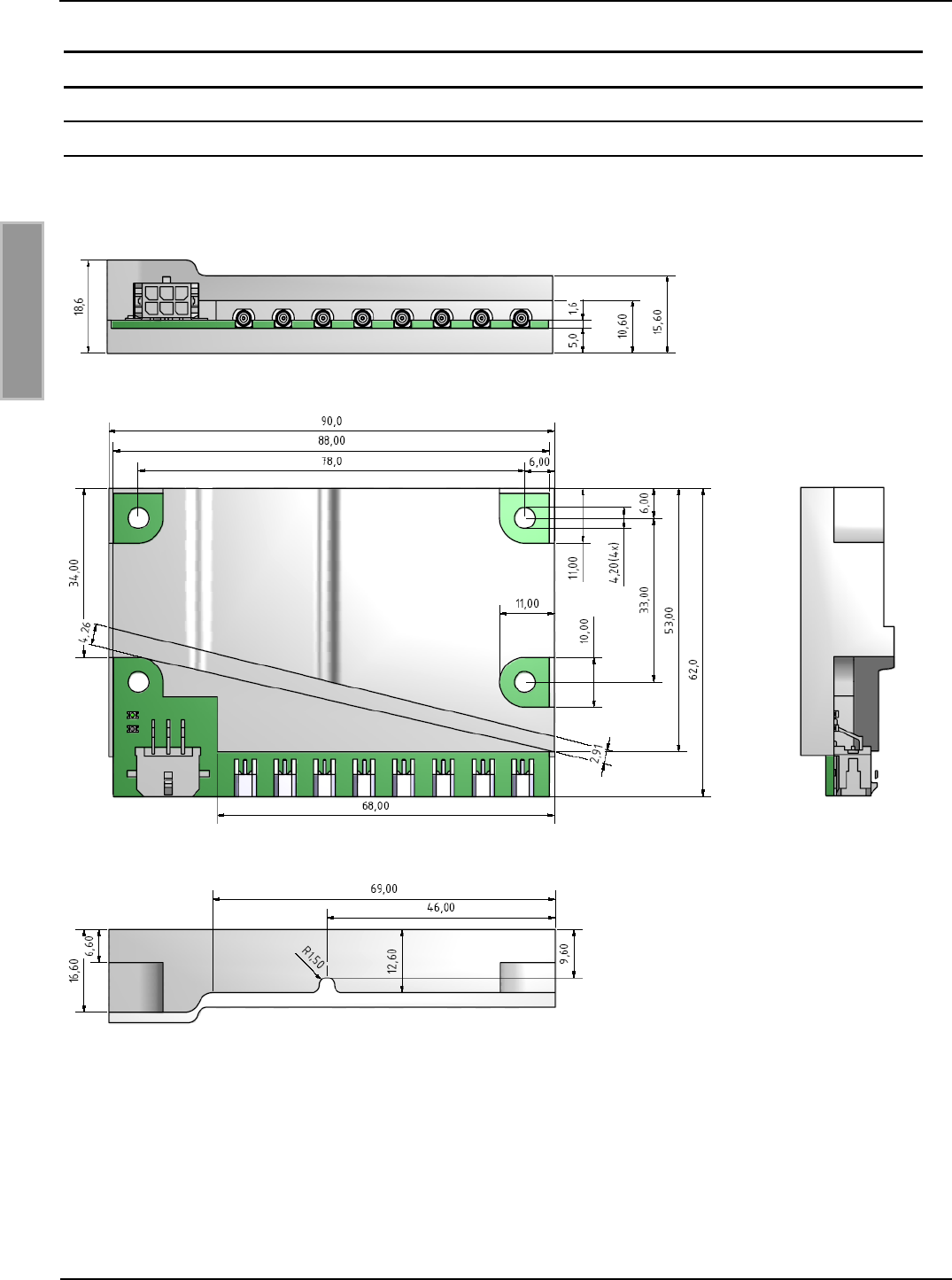
3.1 Abmessungen ............................................................................................................. 7
3.2 Anschlussbelegung X9 .............................................................................................. 8
3.2.1 Spannungsversorgung .................................................................................................. 9
3.2.2 RS232-Schnittstelle ...................................................................................................... 9
3.2.3 Anschluss der externen Antennen .............................................................................. 10
3.3 Montagehinweise ...................................................................................................... 11
3.3.1 Montage ..................................................................................................................... 11
3.3.2 Beeinflussung ............................................................................................................. 11
3.3.3 EMV-Beeinflussung über Zuleitungen ......................................................................... 12
3.3.4 EMV-Beeinflussung über magnetische Felder ............................................................ 12
4 Technische Daten 13
4.1 Zulassung .................................................................................................................. 15
4.1.1 Europa (CE) ................................................................................................................ 15

OBID i-scan®
Montage
RWF1
FEIG ELECTRONIC GmbH
Seite 5 von 31
M90900-4de-ID-E.doc
D E U T S C H
1 Sicherheits- und Warnhinweise - vor Inbetriebnahme unbedingt lesen
Das Gerät darf nur für den vom Hersteller vorgesehenen Zweck verwendet werden.
Die Bedienungsanleitung ist zugriffsfähig aufzubewahren und jedem Benutzer auszuhändigen.
Unzulässige Veränderungen und die Verwendung von Ersatzteilen und Zusatzeinrichtungen,
die nicht vom Hersteller des Gerätes verkauft oder empfohlen werden, können Brände, elektri-
sche Schläge und Verletzungen verursachen. Solche Maßnahmen führen daher zu einem
Ausschluß der Haftung und der Hersteller übernimmt keine Gewährleistung.
Für das Gerät gelten die Gewährleistungsbestimmungen des Herstellers in der zum Zeitpunkt
des Kaufs gültigen Fassung. Für eine ungeeignete, falsche manuelle oder automatische Ein-
stellung von Parametern für ein Gerät bzw. ungeeignete Verwendung eines Gerätes wird keine
Haftung übernommen.
Reparaturen dürfen nur vom Hersteller durchgeführt werden.
Anschluß-, Inbetriebnahme-, Wartungs-, und sonstige Arbeiten am Gerät dürfen nur von Elekt-
rofachkräften mit einschlägiger Ausbildung erfolgen.
Alle Arbeiten am Gerät und dessen Aufstellung müssen in Übereinstimmung mit den nationa-
len elektrischen Bestimmungen und den örtlichen Vorschriften durchgeführt werden.
Beim Arbeiten an dem Gerät müssen die jeweils gültigen Sicherheitsvorschriften beachtet wer-
den.
Besonderer Hinweis für Träger von Herzschrittmachern:
Obwohl dieses Gerät die zulässigen Grenzwerte für elektromagnetische Felder nicht über-
schreitet, sollten Sie einen Mindestabstand von 25 cm zwischen dem Gerät und Ihrem Herz-
schrittmacher einhalten und sich nicht für längere Zeit in unmittelbarer Nähe des Geräts bzw.
der Antenne aufhalten.

OBID i-scan®
Montage
RWF1
FEIG ELECTRONIC GmbH
Seite 6 von 31
M90900-4de-ID-E.doc
D E U T S C H
2 Leistungsmerkmale des Readermoduls RWF1
2.1 Leistungsmerkmale
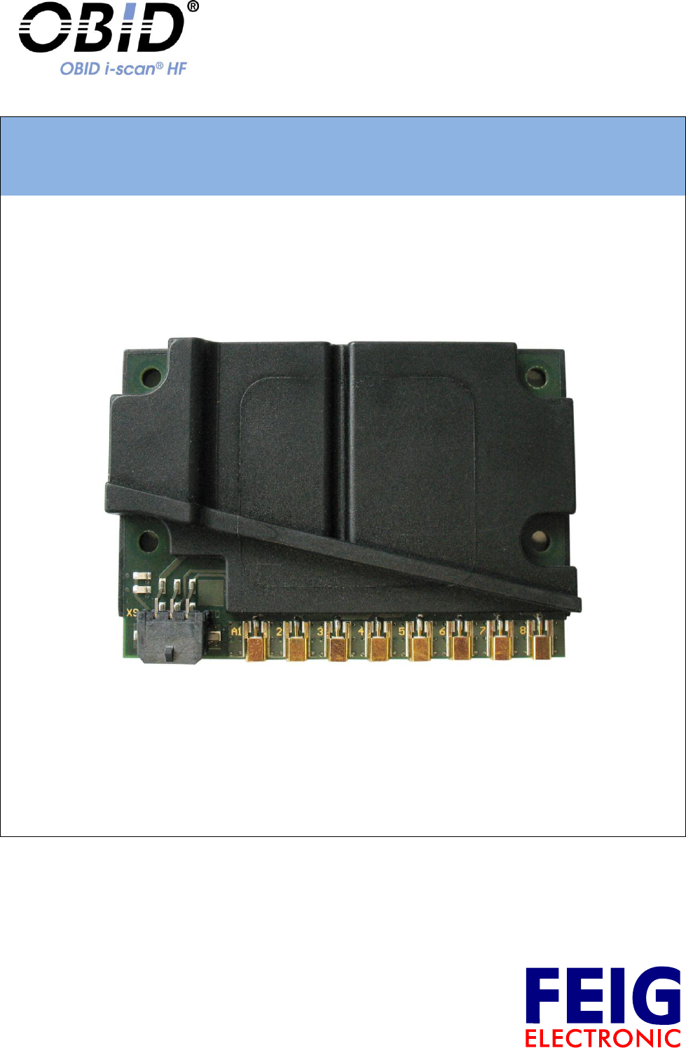
Das Readermodul RWF1 ist für das Lesen und Schreiben von passiven Transpondern mit einer
Betriebsfrequenz von 13,56 MHz nach ISO/IEC 15693 Norm entwickelt worden. Es eignet sich für
alle Anwendungen, bei denen geringe Lesereichweiten bei kleinen Abmessungen des
Readermoduls benötigt werden.
Das Readermodul verfügt über einen internen Antennenmultiplexer. Es können bis zu 8 externe
Antennen an das Modul angeschlossen werden.
2.2 Lieferumfang
Folgende Komponenten sind im Lieferumfang enthalten:
Modultyp
Lieferumfang
RWF1
1 x Readermodul RWF1
Tabelle 1: Lieferumfang
OBID i-scan®
Montage
RWF1
FEIG ELECTRONIC GmbH
Seite 8 von 31
M90900-4de-ID-E.doc
D E U T S C H
3.2 Anschlussbelegung X9
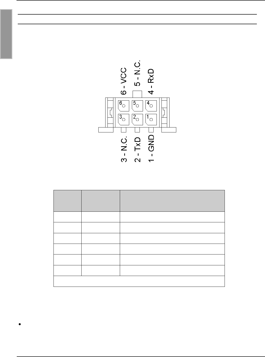
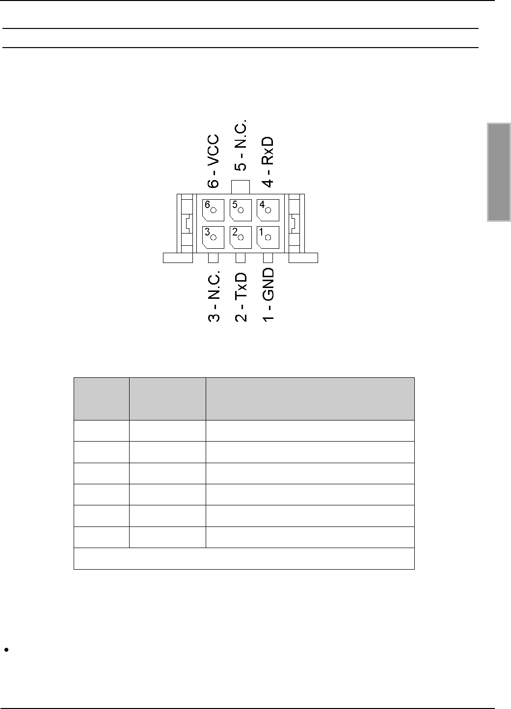
Bild 2 und Tabelle 2 zeigen die Belegung der Anschlusssbuchse X9. Die Anschlusssbuchse X9 ist
für einen Kabelanschluss mittels 6-poligen Anschlussstecker vom Typ Molex MicroFit ausgelegt.
Bild 2 Anschlussbuchse Molex MicroFit, 6Pol.
X9
Pin-Nr.
Kurzzeichen
Beschreibung
1
GND
Ground
2
TxD
RS232 - Sendedaten
3
-
N.C.
4
RxD
RS232 - Empfangsdaten
5
-
N.C.
6
VCC*
24VDC Spannungsversorgung
* Nur geregelte DC-Spannungen verwenden !
Tabelle 2: Belegung der Anschlussstiftleiste X9
HINWEIS:
Eine Verpolung des Steckers kann zur Zerstörung des Gerätes führen.

OBID i-scan®
Montage
RWF1
FEIG ELECTRONIC GmbH
Seite 9 von 31
M90900-4de-ID-E.doc
D E U T S C H
3.2.1 Spannungsversorgung
Für die Spannungsversorgung des RWF1 dürfen nur geregelte DC-Spannungen verwendet
werden.
Im Falle von getakteten Netzteilen zur Versorgung des Readermoduls ist auf eine ausreichende
Filterung der Versorgungsspannung zu achten.
Störungen der Versorgungsspannung können sich in einer Reduzierung der Lese- und Schreib-
reichweite des Readermodules auswirken.
Die Länge des Zuleitungskabels der Spannungsversorgung sollte möglichst kurz sein und sollte
10 m nicht überschreiten. Es sollte ein paarweise verdrilltes Kabel verwendet werden.
HINWEISE:
Eine Verpolung der Versorgungsspannung kann zur Zerstörung des Gerätes führen.
Versorgungsspannungen außerhalb der Spezifikation können zur Zerstörung des Gerä-
tes führen.
3.2.2 RS232-Schnittstelle
Die Länge des Zuleitungskabels der RS232-Schnittstelle sollte möglichst kurz sein und darf 10 m
nicht überschreiten. Die Abhängigkeit von der Baudrate ist zu berücksichtigen.
Die Übertragungsparameter der Schnittstelle sind konfigurierbar.
Tabelle 3 zeigt die Werkseinstellung der RS232-Schnittstelle.
Parameter
Standardeinstellung
Baudrate
38400 bit/s
Anzahl der Datenbits
8
Parität
Even
Anzahl der Stoppbits
1
Tabelle 3: Werkseinstellung der RS232-Schnittstelle.
OBID i-scan®
Montage
RWF1
FEIG ELECTRONIC GmbH
Seite 10 von 31
M90900-4de-ID-E.doc
D E U T S C H
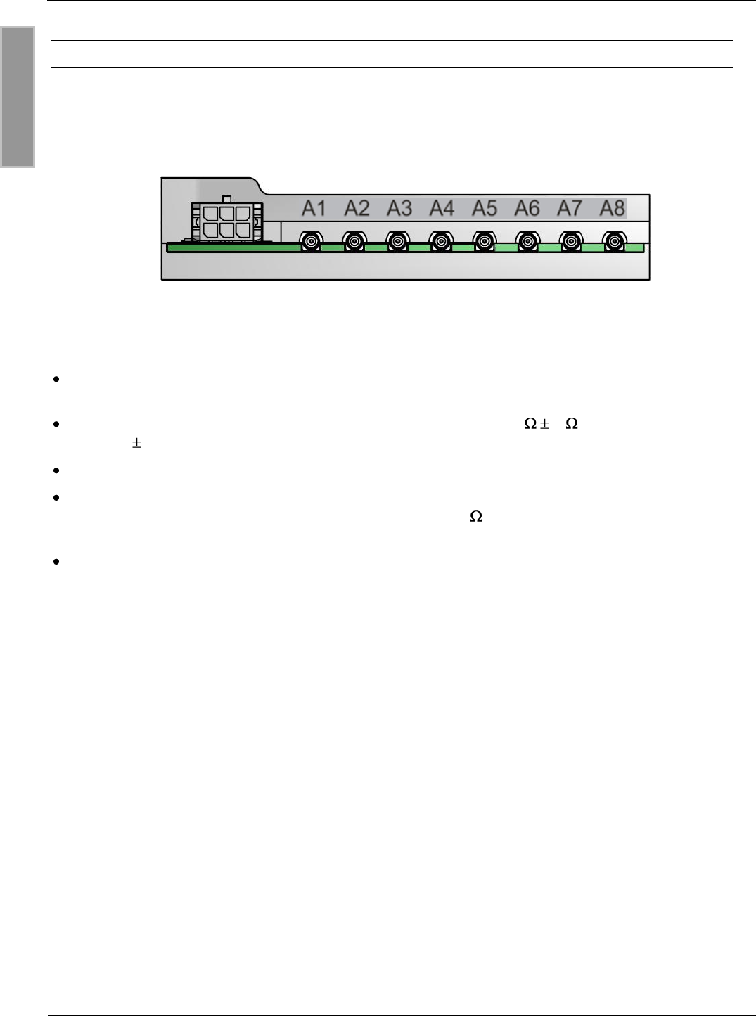
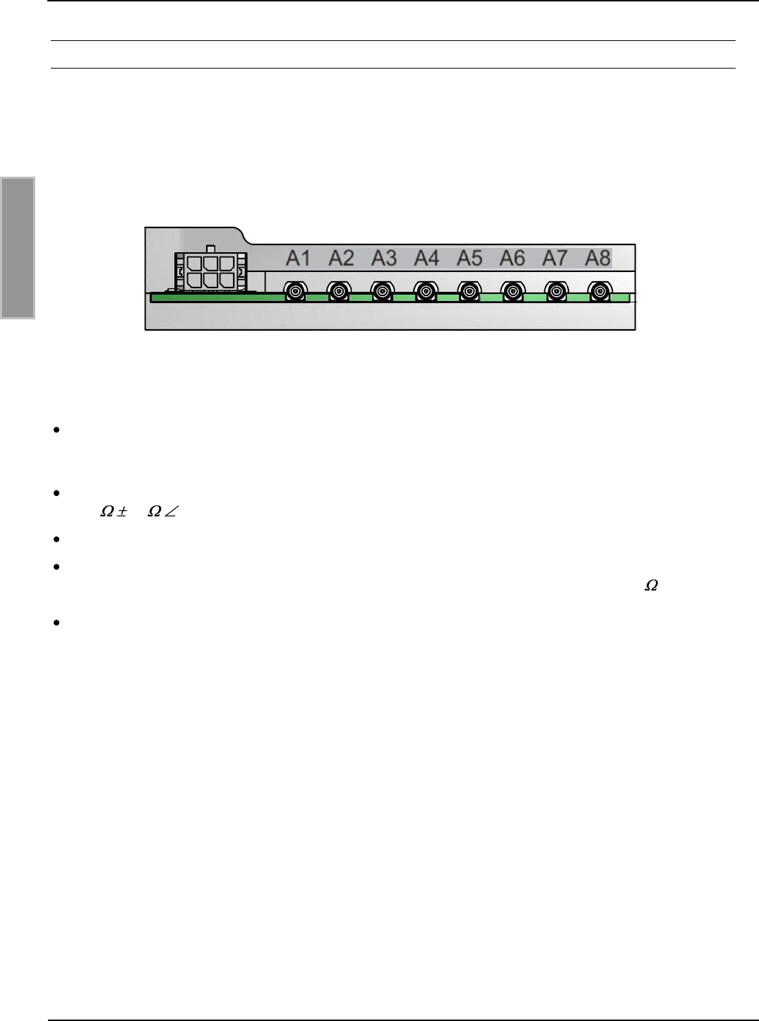
3.2.3 Anschluss der externen Antennen
Es können bis zu 8 externe Antennen angeschlossen werden.
Zum Anschluss der externen Antennen befinden sich 8 Antennenbuchsen (A1...A8) auf der Leiter-
platte. Diese sind vom Typ MMCX.
Bild 3 Antennenanschluss
Hinweise:
Die maximale Antennenzuleitung sollte 150 cm nicht überschreiten. Bei Kabellängen >
100cm ist mit Lesereichweitenverlusten bis zu 10% zu rechnen.
Die Eingangsimpedanz der Antenne ist auf einen Wert von 50 3 und einem Winkel
von 0 ° 3 ° abzugleichen.
Eine nicht abgeglichene Antenne kann zur Zerstörung des Gerätes führen.
Die optimale Betriebsgüte der Antenne sollte im Bereich QB = 10...20 liegen. Zur Ermitt-
lung der Betriebsgüte muss die Antenne mit einer 50 -Quelle, z.B. einem Network Ana-
lyzer oder einem Frequenzgenerator, versorgt werden.
Beim Anschluss einer Antenne ist darauf zu achten, dass diese die zulässigen Grenz-
werte der nationalen Vorschriften bezüglich Funkanlagen nicht überschreitet.

OBID i-scan®
Montage
RWF1
FEIG ELECTRONIC GmbH
Seite 11 von 31
M90900-4de-ID-E.doc
D E U T S C H
3.3 Montagehinweise
Das Antennenmodul ist für den Einbau in andere Geräte konzipiert.
3.3.1 Montage
Das Antennenmodul ist für Schrauben mit einem Gewindedurchmesser M2,5 konzipiert.
Bauteilseite des Readermoduls
Zum befestigen sind Schrauben zu verwenden, deren Kopf einen Durchmesser von 6mm nicht
überschreitet.
Bevorzugt werden nicht metallische Schrauben nach DIN 7985
Alternative Schrauben mit Innensechskant nach DIN 912
Unterseite des Readermoduls
Leitende Materialien dürfen ein maximalen Durchmesser von 6mm haben
Nicht leitende Materialien dürfen ein maximalen Durchmesser von 10mm haben
Die Einbaulage des Antennenmoduls frei wählbar. Die bevorzugte Einbaulage ist jedoch mit
der Bauteilseite nach oben.
Prüfen Sie vor der endgültigen Installation den geplanten Montageort auf seine Tauglichkeit.
3.3.2 Beeinflussung
Folgende mögliche Beeinflussungen durch die Umgebung sollten beim Einbau des Antennenmo-
duls in ein anderes Gerät beachtet werden :
Beeinflussung durch eine metallische Umgebung
Verstimmung der externen Antenne
Beeinträchtigung der Ausbreitung des magnetischen Feldes der Antenne
EMV-Beeinflussung über Zuleitungen
Beeinträchtigung der Kommunikation zwischen Readermodul und Transponder
EMV-Beeinflussungen über magnetische Felder
Beeinträchtigung der Kommunikation zwischen Readermodul und Transponder

OBID i-scan®
Montage
RWF1
FEIG ELECTRONIC GmbH
Seite 12 von 31
M90900-4de-ID-E.doc
D E U T S C H
3.3.3 EMV-Beeinflussung über Zuleitungen
Trotz der internen EMV-Filter innerhalb des Readermoduls kann es durch starke Störungen auf der
Spannungsversorgung zu Beeinträchtigungen der Kommunikation zwischen Readermodul und
Transponder kommen. Dabei wird vor allem der Empfang der Rückantwort des Transponders ge-
stört.
Beim Einbau des Readermoduls in ein anderes Gerät sollte daher auf eine möglichst saubere,
störfreie Spannungsversorgung geachtet werden.
3.3.4 EMV-Beeinflussung über magnetische Felder
Da im vorliegenden Fall der RFID-Technik die Kommunikation zwischen Readermodul und Trans-
ponder mittels der Modulation eines magnetischen Feldes abläuft, können sich magnetische
Wechselfelder in der Nähe der Antenne negativ auf dessen Funktion auswirken.
Zu den Quellen solcher magnetischen Störfelder gehören zum Beispiel Spulen innerhalb eines
primär oder sekundär getakteten Netzteils.
Bei der Festlegung der Position von Readermodul und Antenne in einem Gerät sollte dieses auf
eventuelle Störquelle in der oben angegebenen Form untersucht werden. Notfalls sind Abschirm-
maßnahmen zur Unterdrückung einer solchen Störquelle anzuwenden.

OBID i-scan®
Montage
RWF1
FEIG ELECTRONIC GmbH
Seite 13 von 31
M90900-4de-ID-E.doc
D E U T S C H
4 Technische Daten
Mechanische Daten
Gehäuse
vergossen
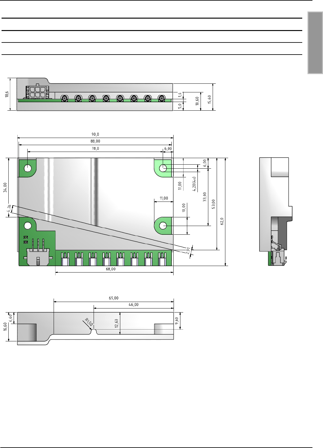
Abmessungen ( B x H x T )
90 x 62 x 18,6 mm
Gewicht
77 g
Anschlussstecker
6poliger Molex MicroFit 6 Stecker
Elektrische Daten
Spannungsversorgung
24V DC ± 10%
Stromaufnahme
max. 100mA
Leistungsaufnahme
max. 2 Watt
Betriebsfrequenz
13,56 MHz
Sendeleistung
200mW ± 1dB
Antennenanschluss
bis zu 8 externe Antennen (50Ohm)
(Anschluss: MMCX-Stecker)
Max. Länge 1,5m (Ab 1m ist mit
Lesereichweitenverlusten bis zu 10% rechnen)
Schnittstellen
RS232 (V24) (Max. Kabellänge 10m)
Funktionelle Eigenschaften
Protokoll Modi
FEIG ISO HOST
Unterstützte Transponder
ISO15693
EEPROM (für Parameter)
1kB (10.000 Schreibzyklen)
FLASH
64 kB (Firmware Update über Interface möglich)

OBID i-scan®
Montage
RWF1
FEIG ELECTRONIC GmbH
Seite 14 von 31
M90900-4de-ID-E.doc
D E U T S C H
Umgebungsbedingungen
Temperaturbereich
- Betrieb
- Lagerung
-20°C to +70°C
-40°C to +85°C
Relative Luftfeuchtigkeit
5 bis 95% nicht betauend
Angewendete Normen
Zulassung Funk
- Europa
- USA
- Canada
- Japan
EN 300 330-1/-2
EN 302 291
FCC 47 CFR Part 15
IC RSS – 210 Issue 8
Radio ordinance item 3 article 44-1
EMC
EN 300 489-1/-3
EN 61326-1/-2-6
Sicherheit
EN 60950
EN 62311
OBID i-scan®
Montage
RWF1
FEIG ELECTRONIC GmbH
Seite 15 von 31
M90900-4de-ID-E.doc
D E U T S C H
4.1 Zulassung
4.1.1 Europa (CE)
Die Funkanlage entspricht, bei bestimmungsgemäßer Verwendung den grundlegenden Anforde-
rungen des Artikels 3 und den übrigen einschlägigen Bestimmungen der R&TTE Richtlinie
1999/5/EG vom März 99.
Equipment Classification gemäß ETSI EN 300 330 und ETSI EN 301 489: Class 2

OBID i-scan®
Mounting Instruction
RWF1
FEIG ELECTRONIC GmbH
Page 16 of 31
M90900-4de-ID-E.doc
E N G L I S H
Note
Copyright 2010-11 by
FEIG ELECTRONIC GmbH
Lange Strasse 4
D-35781 Weilburg-Waldhausen
Tel.: +49 6471 3109-0
http://www.feig.de
With the edition of this document, all previous editions become void. Indications made in this manual may be
changed without previous notice.
Copying of this document, and giving it to others and the use or communication of the contents thereof are
forbidden without express authority. Offenders are liable to the payment of damages. All rights are reserved
in the event of the grant of a patent or the registration of a utility model or design.
Composition of the information in this document has been done to the best of our knowledge. FEIG
ELECTRONIC GmbH does not guarantee the correctness and completeness of the details given in this ma-
nual and may not be held liable for damages ensuing from incorrect or incomplete information. Since, despite
all our efforts, errors may not be completely avoided, we are always grateful for your useful tips.
The instructions given in this manual are based on advantageous boundary conditions. FEIG ELECTRONIC
GmbH does not give any guarantee promise for perfect function in cross environments and does not give
any guaranty for the functionality of the complete system which incorporates the subject of this document.
FEIG ELECTRONIC call explicit attention that devices which are subject of this document are not designed
with components and testing methods for a level of reliability suitable for use in or in connection with surgical
implants or as critical components in any life support systems whose failure to perform can reasonably be
expected to cause significant injury to a human. To avoid damage, injury, or death, the user or application
designer must take reasonably prudent steps to protect against system failures.
FEIG ELECTRONIC GmbH assumes no responsibility for the use of any information contained in this docu-
ment and makes no representation that they free of patent infringement. FEIG ELECTRONIC GmbH does
not convey any license under its patent rights nor the rights of others.
OBID® and OBID i-scan® are registered trademarks of FEIG ELECTRONIC GmbH.
I-CODE® is a registered trademark of Philips Electronics N.V.
Tag-itTM is a registered trademark of Texas Instruments Incorporated.

OBID i-scan®
Mounting Instruction
RWF1
FEIG ELECTRONIC GmbH
Page 17 of 31
M90900-4de-ID-E.doc
E N G L I S H
Contents
1 Safety Instructions / Warning - Read before start-up ! 18
2 Performance Characteristics of the RWF1 Reader Module 19
2.1 Performance Characteristics ................................................................................... 19
2.2 Available module ...................................................................................................... 19
3 Installation and wiring 20
3.1 Dimensions ............................................................................................................... 20
3.2 Wiring ........................................................................................................................ 21
3.2.1 Supply voltage........................................................................................................ 22
3.2.2 RS232-Interface ..................................................................................................... 23
3.2.3 Connection of the external antennas ...................................................................... 24
3.3 Installation notes ...................................................................................................... 25
3.3.1 Mounting ................................................................................................................ 25
3.3.2 Influence ................................................................................................................ 25
3.3.3 EMC effects on cables ........................................................................................... 25
3.3.4 EMC effects from magnetic fields ........................................................................... 26
4 Technical Data 27
5 Radio Approvals 29
5.1 Europe (CE) ............................................................................................................... 29
6 Annex 31
6.1 Accessories .............................................................................................................. 31

OBID i-scan®
Mounting Instruction
RWF1
FEIG ELECTRONIC GmbH
Page 18 of 31
M90900-4de-ID-E.doc
E N G L I S H
1 Safety Instructions / Warning - Read before start-up !
The device may only be used for the intended purpose designed by for the manufacturer.
The operation manual should be conveniently kept available at all times for each user.
Unauthorized changes and the use of spare parts and additional devices which have not been
sold or recommended by the manufacturer may cause fire, electric shocks or injuries. Such
unauthorized measures shall exclude any liability by the manufacturer.
The liability-prescriptions of the manufacturer in the issue valid at the time of purchase are valid
for the device. The manufacturer shall not be held legally responsible for inaccuracies, errors,
or omissions in the manual or automatically set parameters for a device or for an incorrect
application of a device.
Repairs may only be executed by the manufacturer.
Installation, operation, and maintenance procedures should only be carried out by qualified
personnel.
Use of the device and its installation must be in accordance with national legal requirements
and local electrical codes .
When working on devices the valid safety regulations must be observed.
Special advice for carriers of cardiac pacemakers:
Although this device doesn't exceed the valid limits for electromagnetic fields you should keep
a minimum distance of 25 cm between the device and your cardiac pacemaker and not stay in
an immediate proximity of the device respective the antenna for some time.

OBID i-scan®
Mounting Instruction
RWF1
FEIG ELECTRONIC GmbH
Page 19 of 31
M90900-4de-ID-E.doc
E N G L I S H
2 Performance Characteristics of the RWF1 Reader Module
2.1 Performance Characteristics
The RWF1 reader module is designed for reading and writing passive transponders, so-called
“Smart Labels”, with an operating frequency of 13.56 MHz according to the ISO15693 standard. It
is suitable for any application in which short read ranges and small reader dimensions are re-
quired.
The module has an integrated antenna multiplexer. Up to 8 external antennas can be connected.
2.2 Available module
The following reader types are available:
Module type
Description
RWF1
1 x Reader module RWF1 (RWF1)
Table 1: Available module version
OBID i-scan®
Mounting Instruction
RWF1
FEIG ELECTRONIC GmbH
Page 21 of 31
M90900-4de-ID-E.doc
E N G L I S H
3.2 Wiring
Fig. 2 and Table 2 show the pin assignments for Terminal X9. The pin connector is designed for
cable connection using a 6 pin multipoint socket connector typ Molex MicroFit.
Fig. 2 Terminal Molex MicroFit, 6pin.
X9
Pin-No.
Function
Description
1
GND
Ground
2
TxD
RS232 – Transmit Data
3
-
N.C.
4
RxD
RS232 – Receive Data
5
-
N.C.
6
VCC*
24VDC Power Supply
* Use regulated DC power supplies only!
Table 2: Pin Assignment of the multipoint connector X9
Note:
A wrong polarity of the DC voltage will destroy the reader

OBID i-scan®
Mounting Instruction
RWF1
FEIG ELECTRONIC GmbH
Page 22 of 31
M90900-4de-ID-E.doc
E N G L I S H
3.2.1 Supply voltage
The RWF1 must be supplied only by a regulated power supply.
If switching power supplies are used with the module, be sure that there is adequate filtering.
Noise from the power supply can result in a reduction of the read/write range of the module.
The cable length from the power supply should be as short as possible, and should in any case not
exceed 10 m. A twisted pair cable is recommended.
Note:
A wrong polarity of the DC voltage will destroy the reader
Supply voltages outside the specifications may destroy the device.

OBID i-scan®
Mounting Instruction
RWF1
FEIG ELECTRONIC GmbH
Page 23 of 31
M90900-4de-ID-E.doc
E N G L I S H
3.2.2 RS232-Interface
The length of the cable to the RS232 interface should be kept as short as possible, and should not
exceed 10m. The dependence of the baud rate has to be considered.
The transmission parameters for the interface can be software-configured.
Table 3 shows the standard parameters for the RS232 interface.
Parameter
Default Setting
Baudrate
38400 bit/s
Number of Databits
8
Parity
Even
Number of Stopbits
1
Table 3 Default parameter of the RS232
OBID i-scan®
Mounting Instruction
RWF1
FEIG ELECTRONIC GmbH
Page 24 of 31
M90900-4de-ID-E.doc
E N G L I S H
3.2.3 Connection of the external antennas
Up to 8 external antennas can be connected.
For the connection of the external antennas 8 antenna connectors (A1...A8) are available.
The connector type is MMCX.
Fig. 3 Antenna connector„s
Note:
The maximum antenna cable length should not increase a maximum length of 150cm
(24inch). Cable length more than one meter can result in a shorter reading distance up
to -10%.
The input impedance for the antenna must be calibrated to a value of
50 (3 3°).
A not correct tuned antenna can destroy the reader.
The optimum working quality of the antenna should be in a range of QB = 10...20.
For measuring the working quality the antenna must be connected with a 50 -source,
e.g. a network analyzer or a frequency generator
When connecting an antenna, ensure that it does not exceed the permissible limits pre-
scribed by the national regulations for radio frequency devices.

OBID i-scan®
Mounting Instruction
RWF1
FEIG ELECTRONIC GmbH
Page 25 of 31
M90900-4de-ID-E.doc
E N G L I S H
3.3 Installation notes
The reader module has been designed for the installation in a device.
3.3.1 Mounting
The reader module can be mounted by using 2,5mm (M2,5) screws.
Component side: the maximum head diameter should not increase more than 6mm.
Preferred no metallic screws should be used (DIN7985).
Alternatively internal hexagon screws can be used (DIN 912).
Component underside: conductive materials can have a diameter of 6mm.
Non-conductive materials can have a diameter of up to 10mm.
The mounting orientation of the reader module is arbitrary. The component side on the top is
the preferred orientation.
Check the planed mounting place first for suitability.
3.3.2 Influence
Be aware of the following possible environmental factors when installing the module into another
device :
Effects from nearby metal objects
Detuning of the integrated antenna
Impaired propagation of the antenna‟s magnetic field
EMC effects on cables
Impaired communication between reader and transponder
EMC effects from magnetic fields
Impaired communication between reader and transponder
3.3.3 EMC effects on cables
In spite of the internal EMC filters inside the reader, high levels of noise on the supply voltage can
result in impairment of the communication between the reader and transponder.
When installing an reader module into another device, be sure therefore that a clean, noise-free
power supply is used.

OBID i-scan®
Mounting Instruction
RWF1
FEIG ELECTRONIC GmbH
Page 26 of 31
M90900-4de-ID-E.doc
E N G L I S H
3.3.4 EMC effects from magnetic fields
Since in this type of RFID-Technology the communication between the reader and transponder
takes place by modulation of a magnetic field, alternating magnetic fields in the vicinity of the an-
tenna can have a negative impact on its function.
Sources of such magnetic interference fields include coils within a primary or secondary switching
power supply.
When determining the position of the reader and antenna within a device, check the device for any
possible sources of interference as described above. If necessary, use shielding to suppress such
interference.

OBID i-scan®
Mounting Instruction
RWF1
FEIG ELECTRONIC GmbH
Page 27 of 31
M90900-4de-ID-E.doc
E N G L I S H
4 Technical Data
Mechanical Data
Housing
(sealed-in electronics)
Dimensions (W x H x D)
90 x 62 x 18,6 mm (3.54 x 2.44 x 0.73 inch)
Weight
77 g
Connector
6 Pin Molex MicroFit 6 plug
Electrical Data
Supply voltage
24V DC ± 10%
Current draw
max. 100mA
Power consumption
max. 2 Watt
Operating frequency
13,56 MHz
Transmitting power
200mW ± 1dB
Antenna connection
up to 8 external Antennas (50Ohm)
(Connector: MMCX)
Max. cable lentgh1,5m. (by cable length from 1m -
1,5m a reduced reading distance of 10% is possible)
Interface
RS232 – (V24) (max. Cable length 10m)
Functional Properties
Protocol Modes
FEIG ISO HOST
Supported transponders
ISO15693
EEPROM (for parameters)
1kB (10.000 write cycles)
FLASH
64 kB (Firmware Update via interface possible)

OBID i-scan®
Mounting Instruction
RWF1
FEIG ELECTRONIC GmbH
Page 28 of 31
M90900-4de-ID-E.doc
E N G L I S H
Ambient Conditions
Temperature range
- Operation
- Storage
-20°C to +70°C (-4°F to 158°F)
-40°C to +85°C (-40°F to 185°F)
Humidity
5 – 95% non condensing
Applicable Norms
Radio approval
- Europe
- USA
- Canada
- Japan
EN 300 330-1/-2
EN 302 291
FCC 47 CFR Part 15
IC RSS – 210 Issue 8
Radio ordinance item 3 article 44-1
EMC
EN 300 489-1/-3
EN 61326-1/-2-6
Safety
EN 60950
EN 62311
OBID i-scan®
Mounting Instruction
RWF1
FEIG ELECTRONIC GmbH
Page 29 of 31
M90900-4de-ID-E.doc
E N G L I S H
5 Radio Approvals
5.1 Europe (CE)
When used according to regulation, this radio equipment conforms with the basic requirements of
Article 3 and the other relevant provisions of the R&TTE Guideline 1999/E6 dated March 99.
Equipment Classification gemäß ETSI EN 300 330: Class 2

OBID i-scan®
Mounting Instruction
RWF1
FEIG ELECTRONIC GmbH
Page 30 of 31
M90900-4de-ID-E.doc
E N G L I S H
Product names:
RWF1
Reader name:
RWF1
FCC ID:
IC:
YQF-RWF1
3100D-RWF1
Notice for USA and
Canada
This device complies with Part 15 of the FCC Rules and with
RSS-210 of Industry Canada.
Operation is subject to the following two conditions.
(1) this device may not cause harmful interference, and
(2) this device must accept any interference received,
including interference that may cause undesired operation.
Unauthorized modifications may void the authority granted under
Federal communications Commission Rules permitting the operation
of this device.
This equipment has been tested and found to comply with the limits for
a Class A digital device, pursuant to Part 15 of the FCC Rules. These
limits are designed to provide reasonable protection against harmful
interference when the equipment is operated in a commercial
environment. This equipment generates, uses, and can radiate radio
frequency energy and, if not installed and used in accordance with the
instruction manual, may cause harmful interference to radio
communications. Operation of this equipment in a residential area is
likely to cause harmful interference in which case the user will be
required to correct the interference at his own expense.
Le présent appareil est conforme aux CNR d'Industrie Canada appli-
cables aux appareils radio exempts de licence. L'exploitation est auto-
risée aux deux conditions suivantes :
(1) l'appareil ne doit pas produire de brouillage, et
(2) l'utilisateur de l'appareil doit accepter tout brouillage radioélectrique
subi, même si le brouillage est susceptible d'en compromettre le fonc-
tionnement.
Warning: Changes or modification made to this equipment not expressly approved by
FEIG ELECTRONIC GmbH may void the FCC authorization to operate this equipment.

OBID i-scan®
Mounting Instruction
RWF1
FEIG ELECTRONIC GmbH
Page 31 of 31
M90900-4de-ID-E.doc
E N G L I S H
6 Annex
6.1 Accessories
The following accessories are available for the Reader.
Article No.
Part No.
Description
3482.000.00.00
ID ISC.ANT30/26-Ro HF
Antenne Roche
External antenna (PCB board)
Dimensions: 30mm x 26mm
Table 4: Accessories