Rockwell Collins 8222132 Rockwell Collins TSS-4100 Integrated Surveillance System User Manual Manual 2
Rockwell Collins Inc Rockwell Collins TSS-4100 Integrated Surveillance System Manual 2
UserManual.wiki
>
Rockwell Collins
>
8222132 User Manual
>
Manual 2
Contents
1.
Manual 1
2.
Manual 2
Manual 2
Navigation menu
Upload a User Manual
Namespaces
Wiki Guide
HTML
PDF
Info
Views
User Manual
Discussion / Help
Navigation
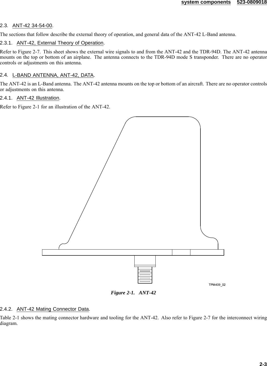
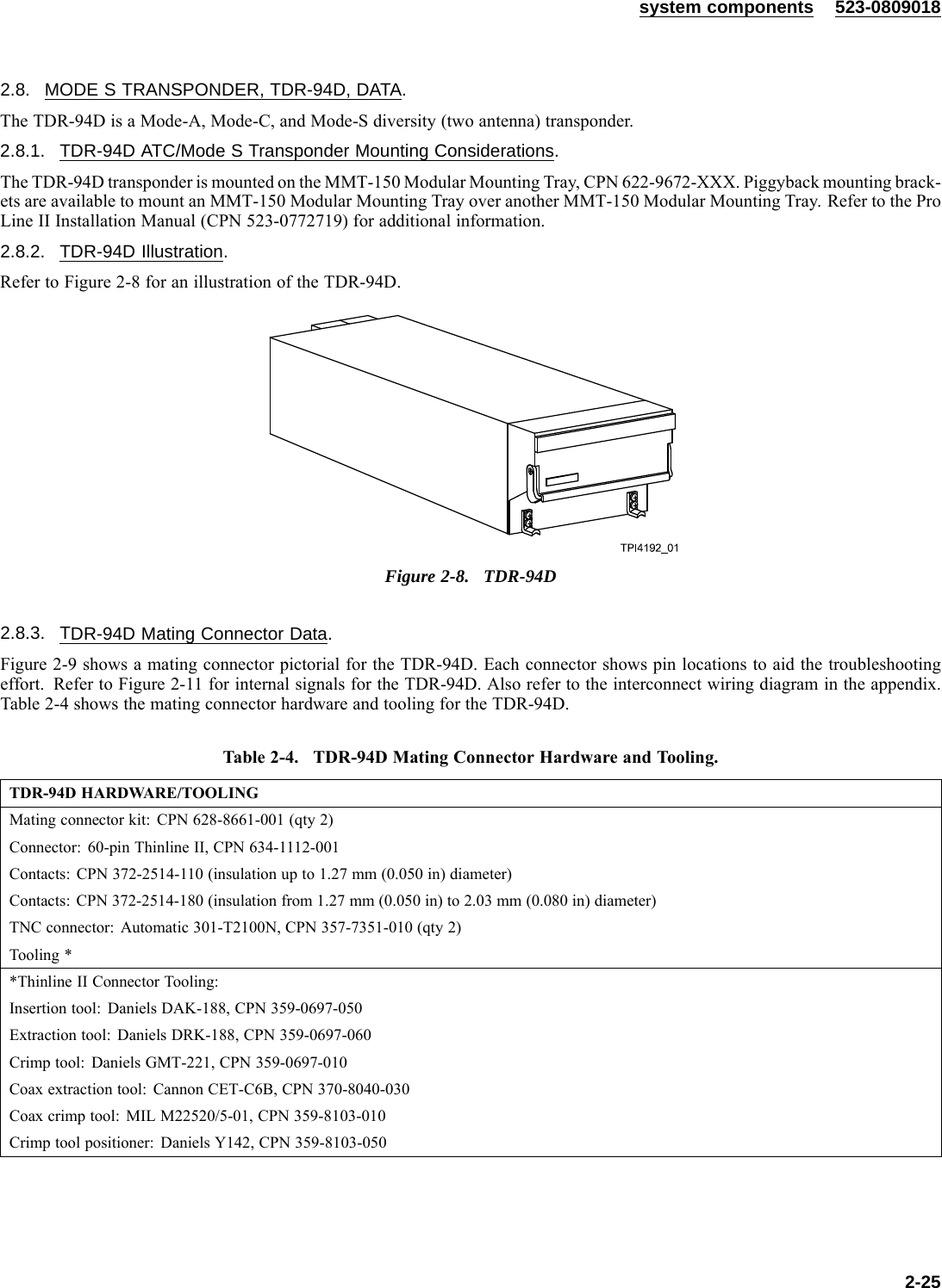
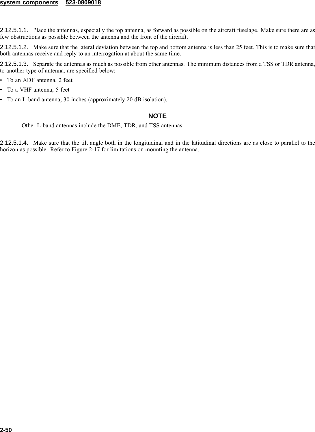
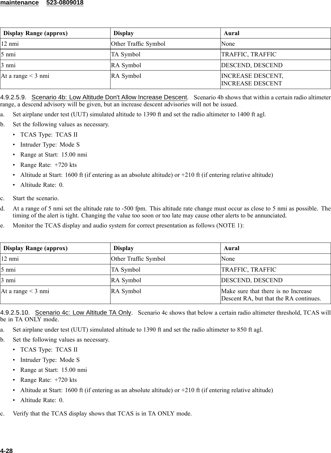
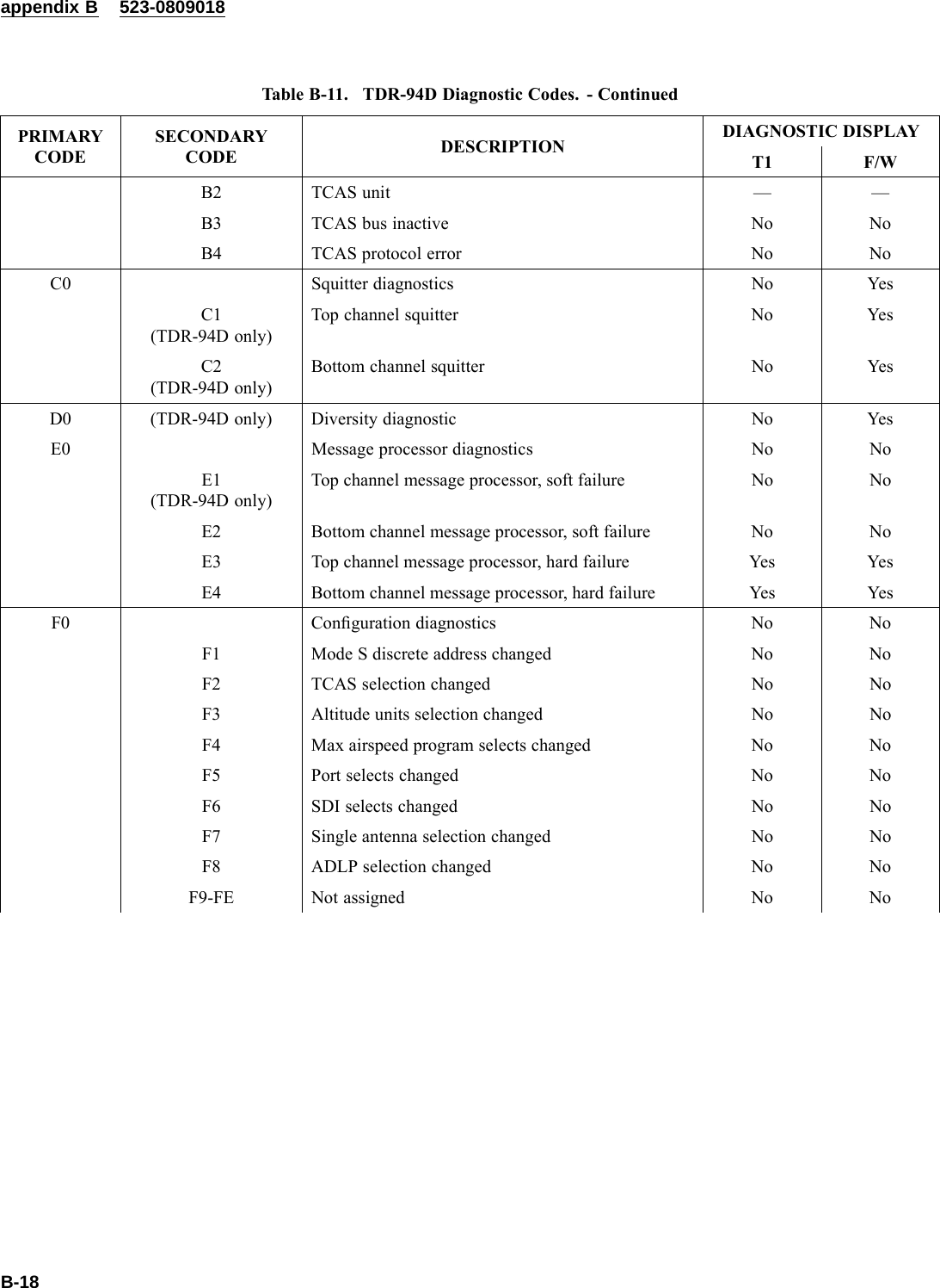
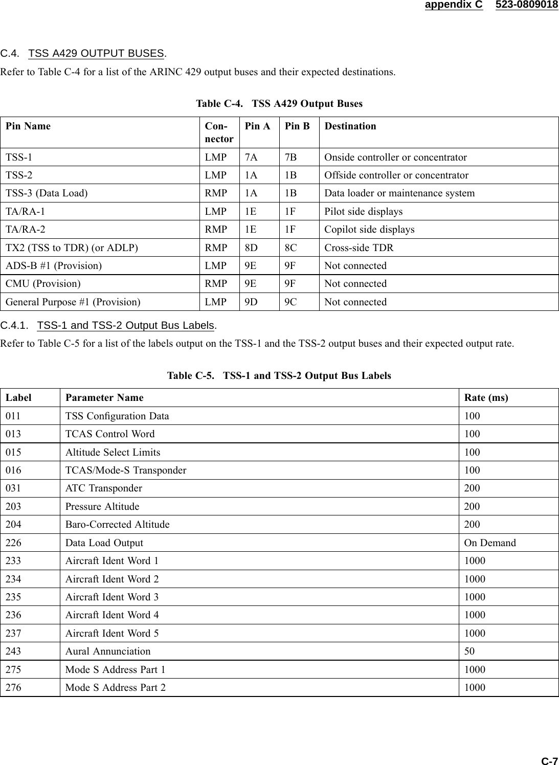
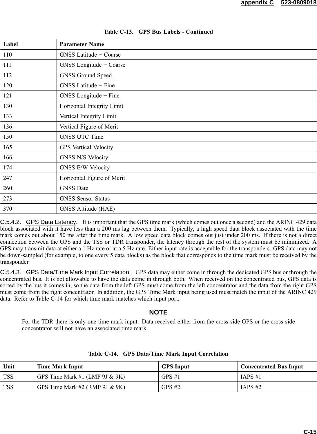
![523-0809018SAFETY SUMMARY1. GENERAL SAFETY INSTRUCTIONS.This manual describes physical and chemical processes which may cause injury or death to personnel or damage to equipment ifnot properly followed. This safety summary includes general safety precautions and instruction that must be understood and appliedduring operation and maintenance to make sure personnel safety and protection of equipment. Prior to performing any task, theWARNING, CAUTIONS, and NOTES included in that task shall be reviewed and understood.2. WARNING, CAUTIONS AND NOTES.WARNINGS and CAUTIONS are used in this manual to highlight operating or maintenance procedures, practices, conditions orstatements which are considered essential to protection of personnel (WARNING) or equipment (CAUTION). WARNINGS andCAUTIONS immediately precede the step or procedure to which they apply. WARNINGS and CAUTIONS consist of four parts:heading (WARNINGS, CAUTIONS or Icon [HAZARDOUS MATERIALS WARNING ]), a statement of the hazard, minimumprecautions, and possible result if disregarded. NOTES are used in this manual to highlight operating or maintenance procedures,practices, conditions or statements which are not essential to protection of personnel or equipment. NOTES may precede or followthe step or procedure, depending upon the information to be highlighted. The headings used and definitions are as follows.Highlights an essential operating or maintenance procedure, practice, condition, or statement, etc. which if notstrictly observed, could result in injury to, or death of, personnel or long term health hazards.Highlights an essential operating or maintenance procedure, practice, condition, or statement, etc. which if notstrictly observed, could result in damage to, or destruction of, equipment or loss of mission effectiveness.NOTEHighlights an essential operating or maintenance procedure, condition, or statement.xiii/(xiv Blank)](https://usermanual.wiki/Rockwell-Collins/8222132.Manual-2/User-Guide-1135854-Page-19.png)
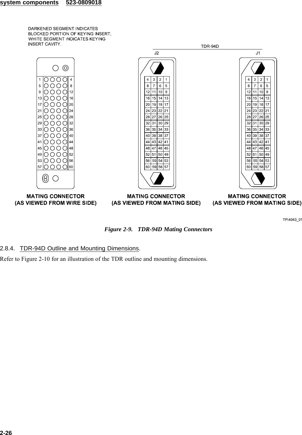
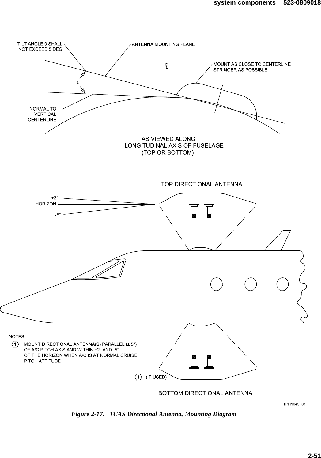
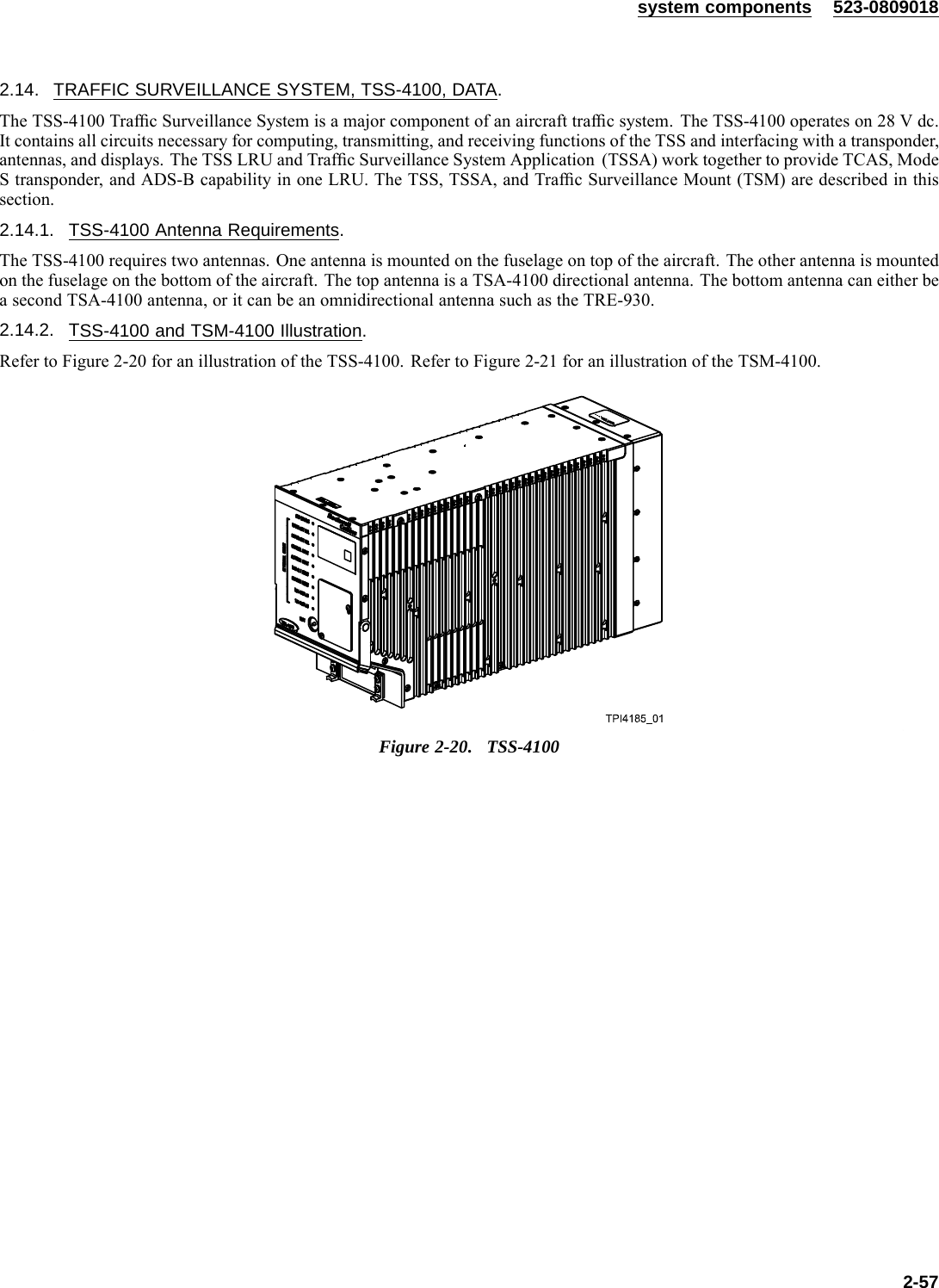
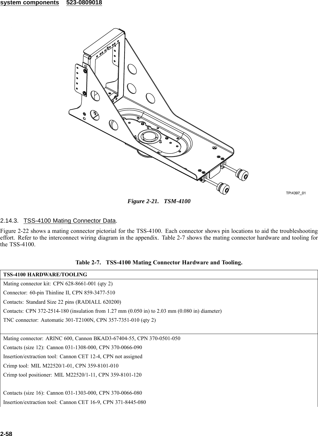
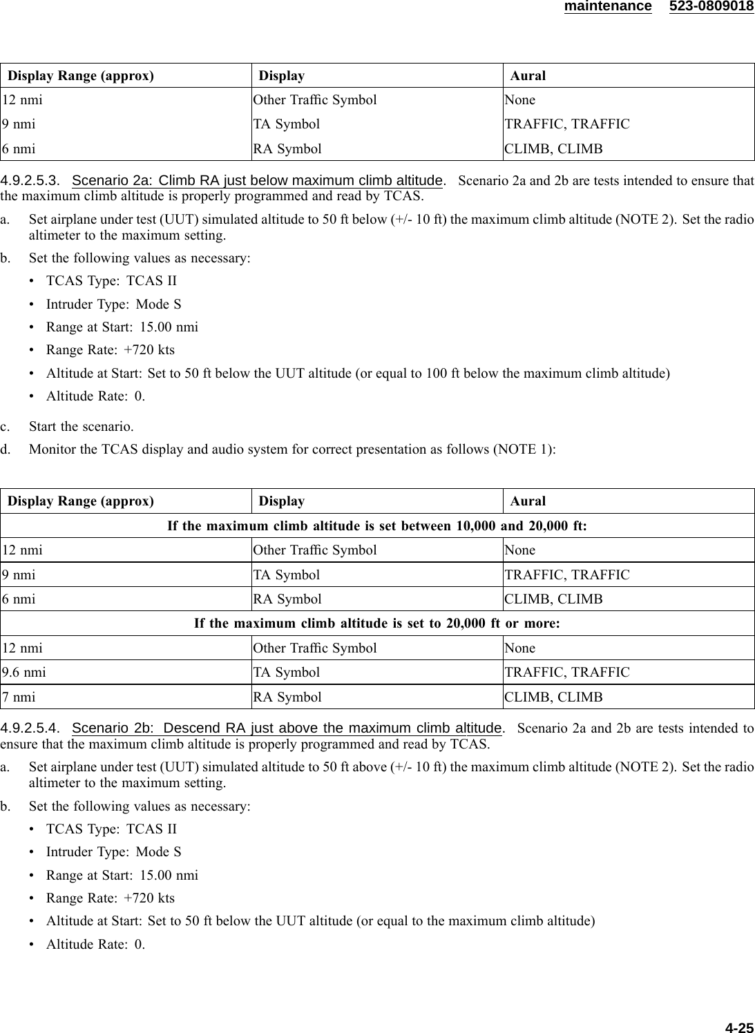
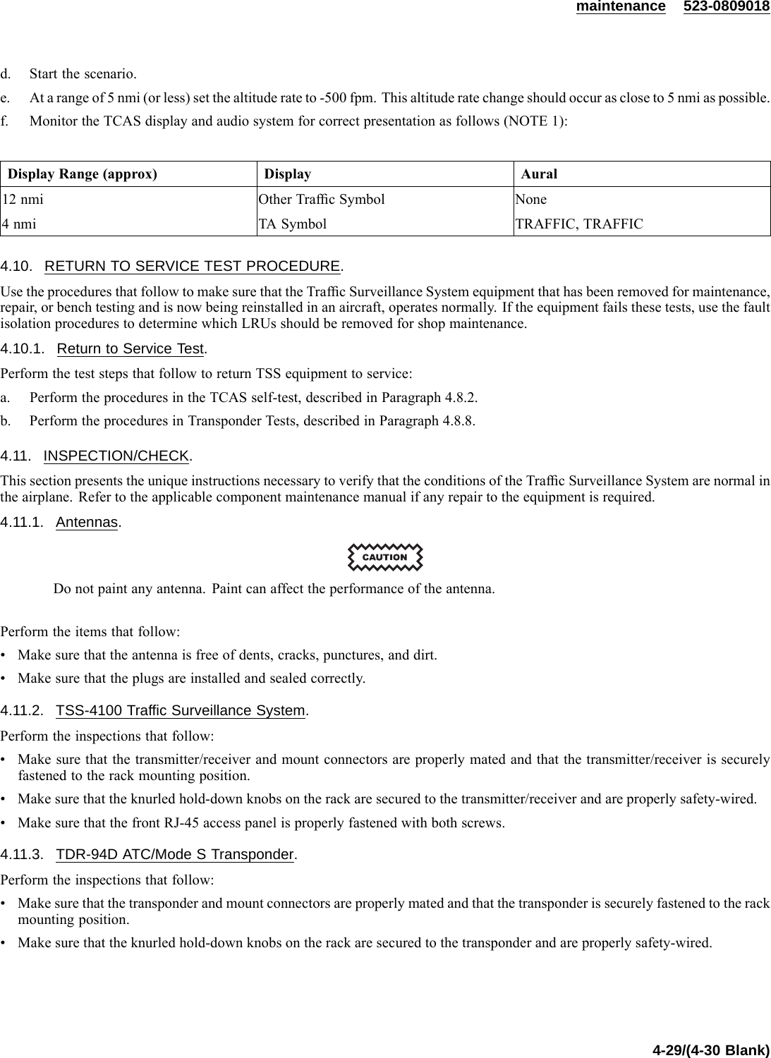
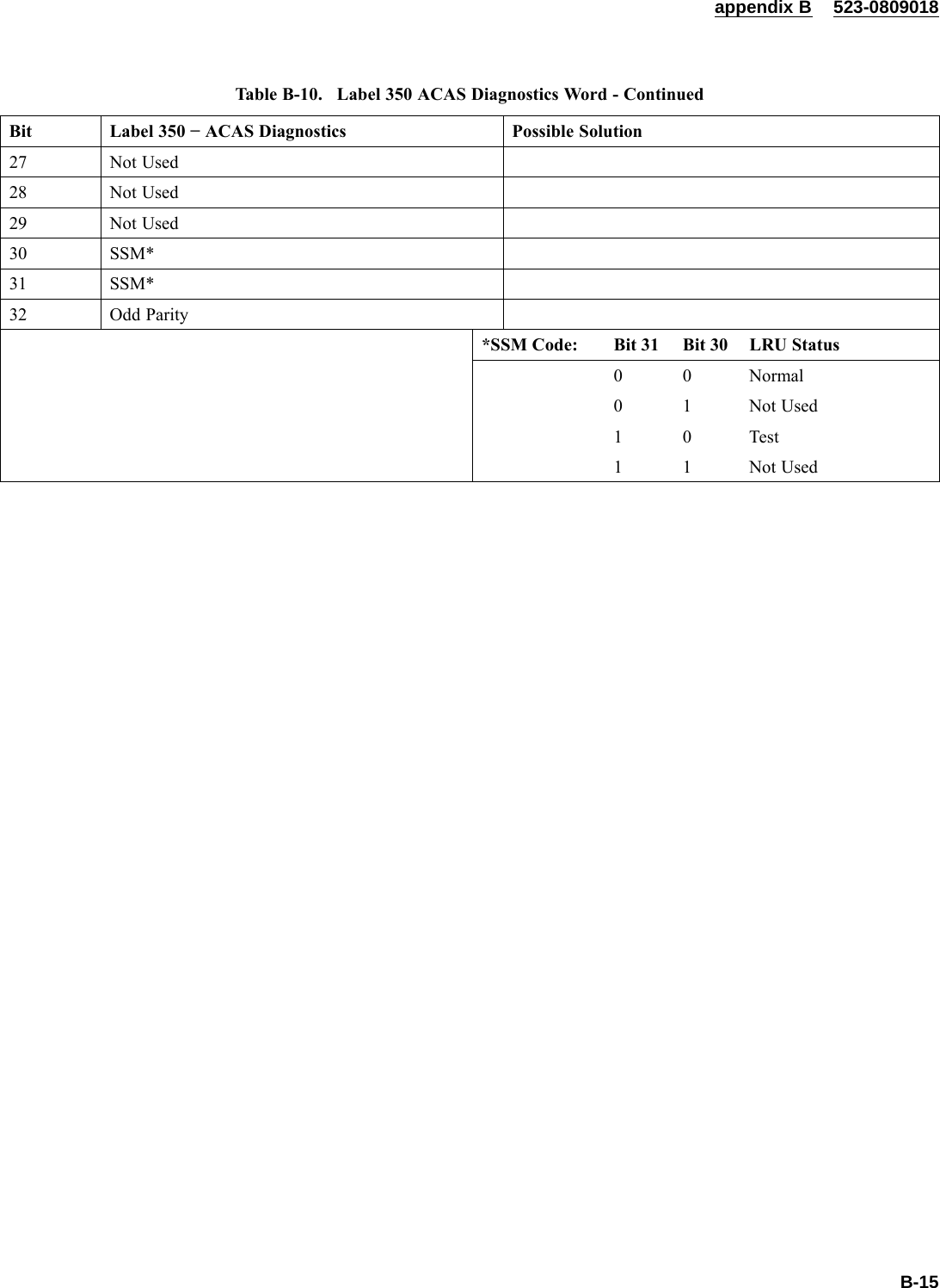
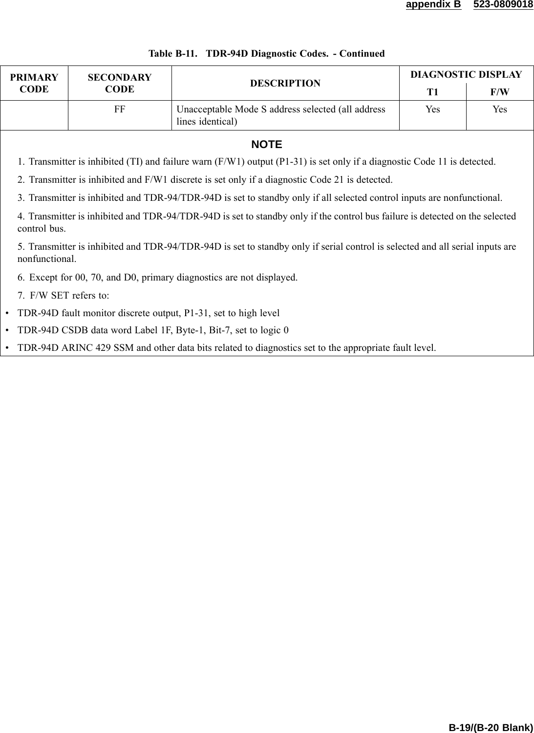
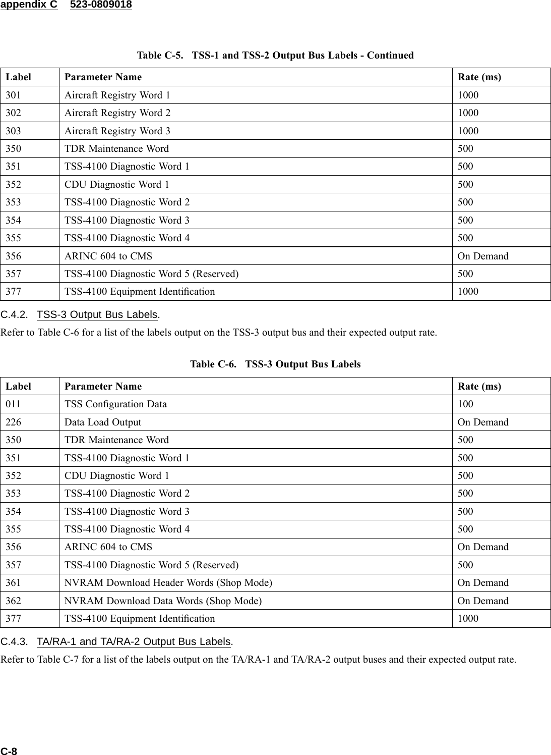
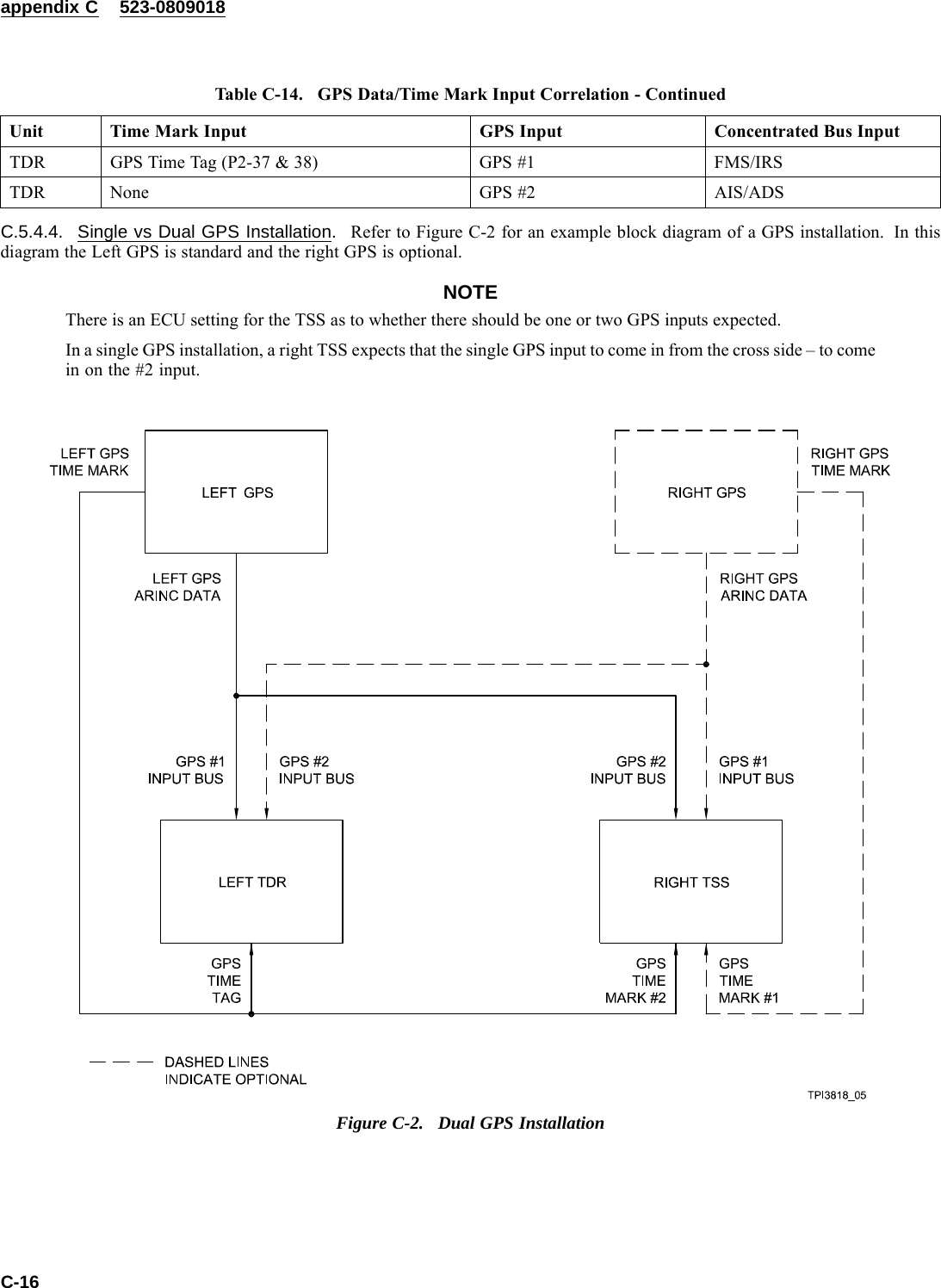
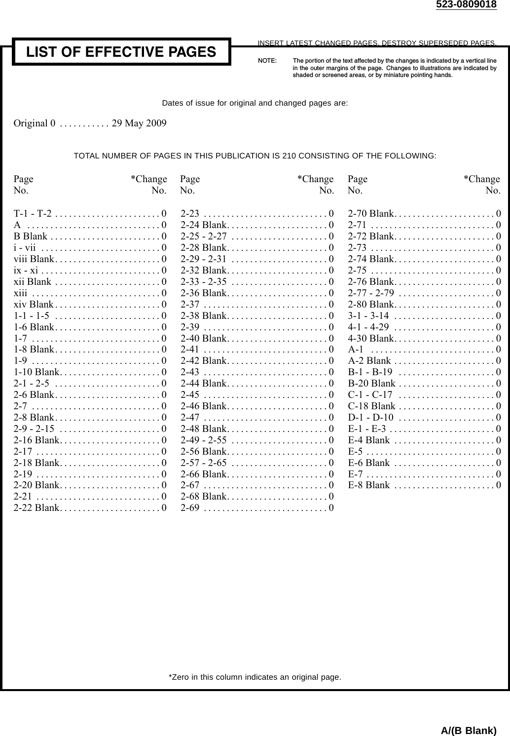
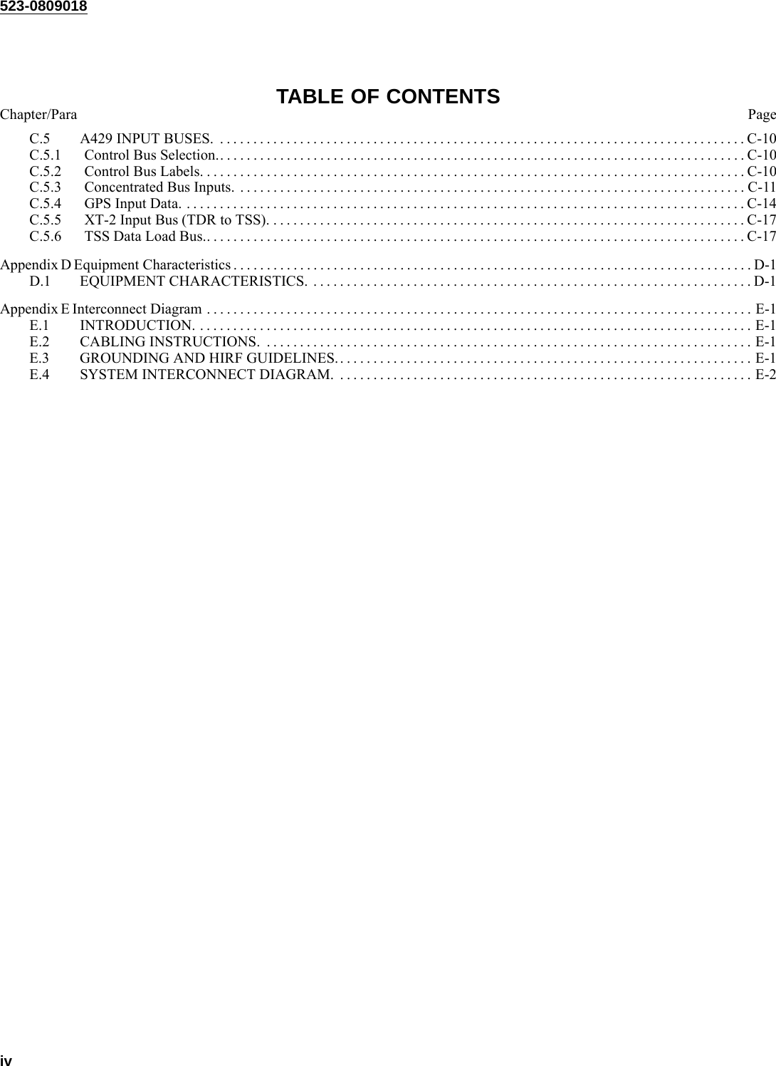
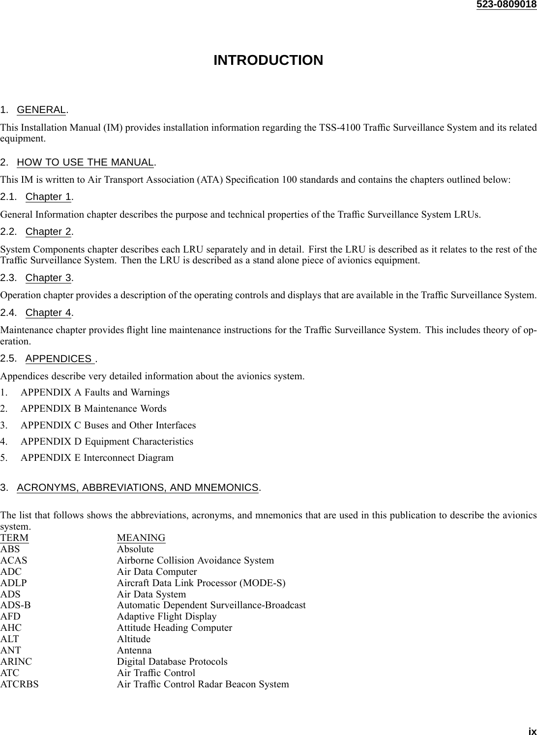
![appendix D 523-0809018Table D-2. Certification Categories.Unit FAA TSO Environmental CategoriesANT-42 C66b,C74c DO-160A E1/B/JLY/XRHXXXXXXXXECU-3000 TSO-C112 & TSO-C119b (-802status)+ TSO-C166a Transmit only(-803 status)DO-160E [(F2)(A2)V]ABB[(RBB1)(SCLM)(HR)]EYXXXXZ[AB]AZ[CC] [RR]M[X][X]AAXTDR-94D TSO-C112 Class 3A2 121 011 Level3esDO-160E [(A2)(E1)-]BBA[SCLM] EXXXFXZZAZZC[RR]M[(A3)(Z3)X]XXAXTRE-930 C66, C74 DO-108 ABAXXXXCL1NOTEThis unit is not tested to DO-160 levels.TSA-4100 TSO-C112, TSO-C119b &TSO-C166a Transmit only.DO-160E [(D2)(F2)X]ABB[(RCC1)(HR)(SLM)]XSFDFSZ[X]XX[CW] [RR]H[(XX)(K4)4][1A]AAXTSS-4100 TSO-C112 Class 2A1 121 011 Level2es, TSO-C119b & TSO-C166aTransmit OnlyDO-160E [(F2)(A2)V]ABB[(RBB1)(SCLM)(HR)]EYXXXXZ[AB]AZ[CC] [RR]M[(B3)(K3)3]XAAXTable D-3. Unit Weight, Power Requirements, and Size.UNIT WEIGHTkg (lb)POWER(Nominal)POWER(Max) SIZE(H×W×L)mm(in)ANT-42 96 (0.2) NotApplicable (NA)84.1 x 44.5 x 115.3 (3.31 x 1.75 x 4.45)TSA-4100 1.0 (2.2) NA 33.0 x 160 x 284.5 (1.30 x 6.30 x 11.20)NOTEHeight does not include length of connector. The-101 connector is 20 mm long. The -001 connec-tor is 39 mm long.ECU-3000 0.08 (0.17) Powered byTSS-410036x51x70(1.4x2.0x2.8)TDR-94/94D 3.86 (8.5) 28.0 W 85.0 x 124 x 353 (3.31 x 4.87 x 14.0) (1/2 ATR,short-low)TRE-930 0.17 (0.38) NA 84 x 44 x 133 (3.3 x 1.7 x 5.24)TSS-4100 7.55 (16.6) 85 W 120 W 194 x 129 x 382 (7.64 x 5.08 x 15.0)D-2](https://usermanual.wiki/Rockwell-Collins/8222132.Manual-2/User-Guide-1135854-Page-196.png)
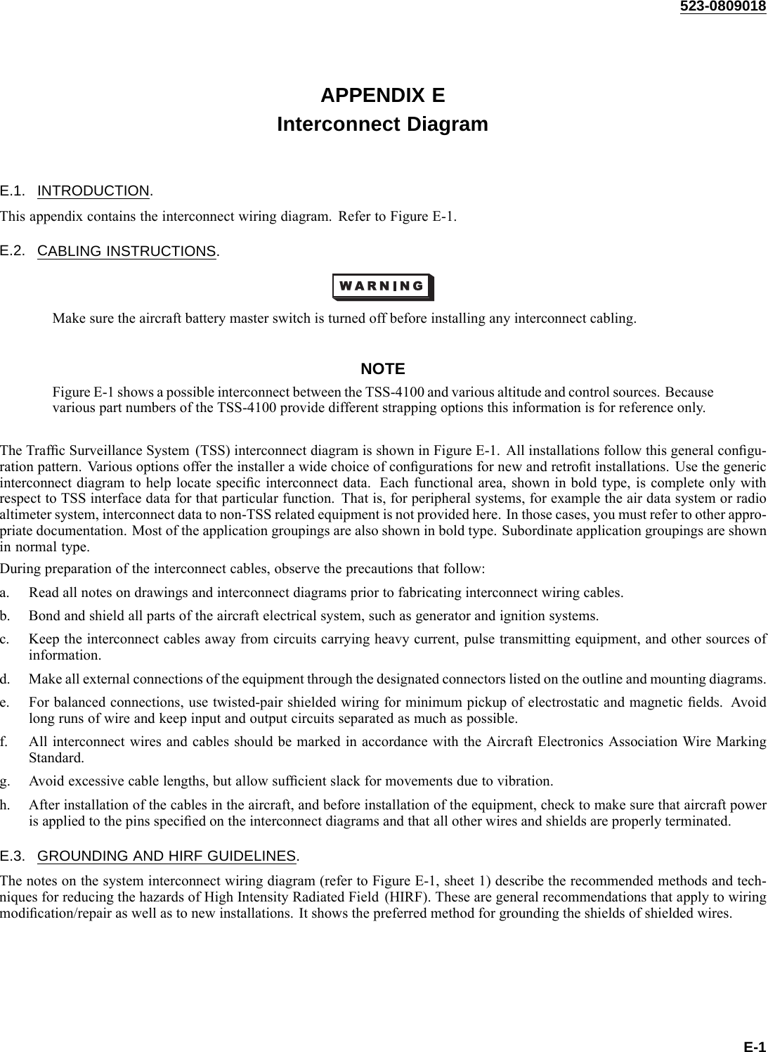
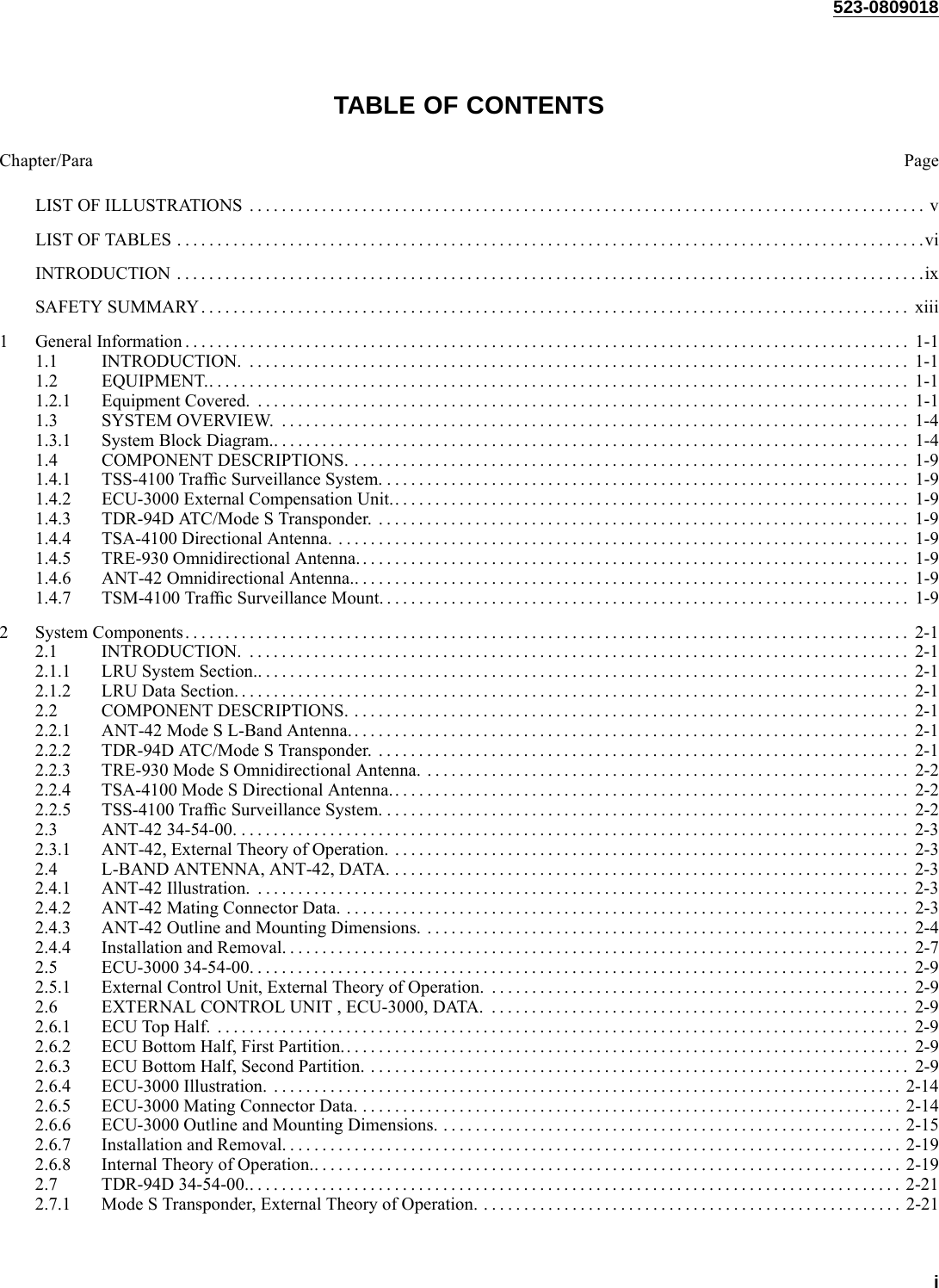
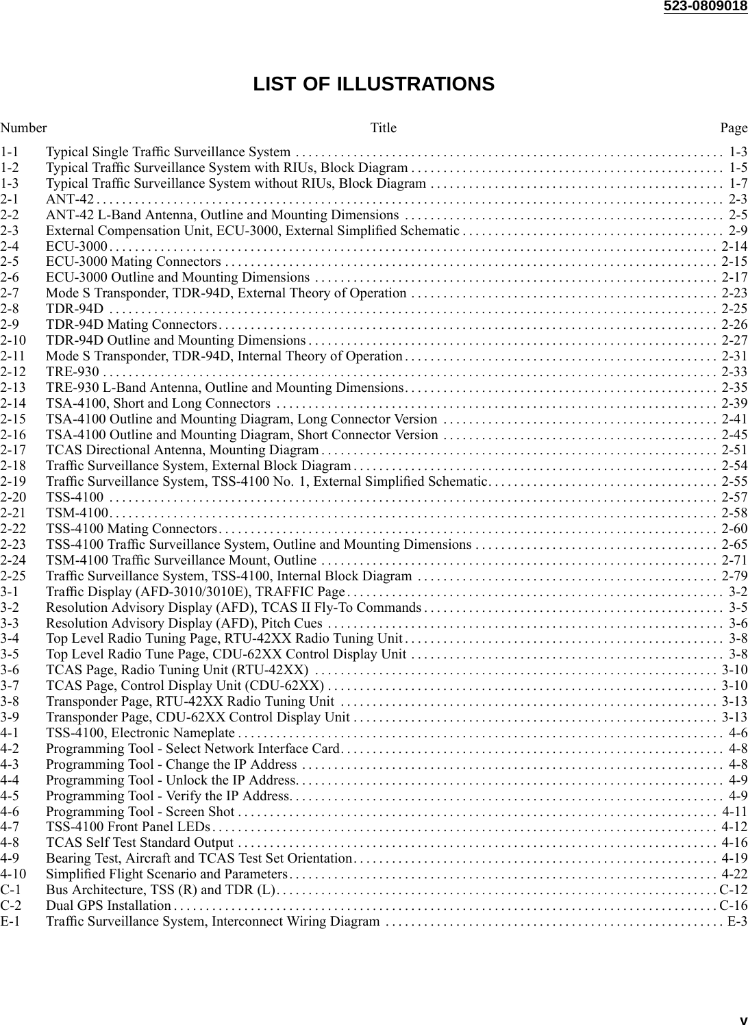
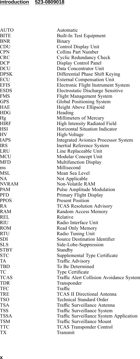
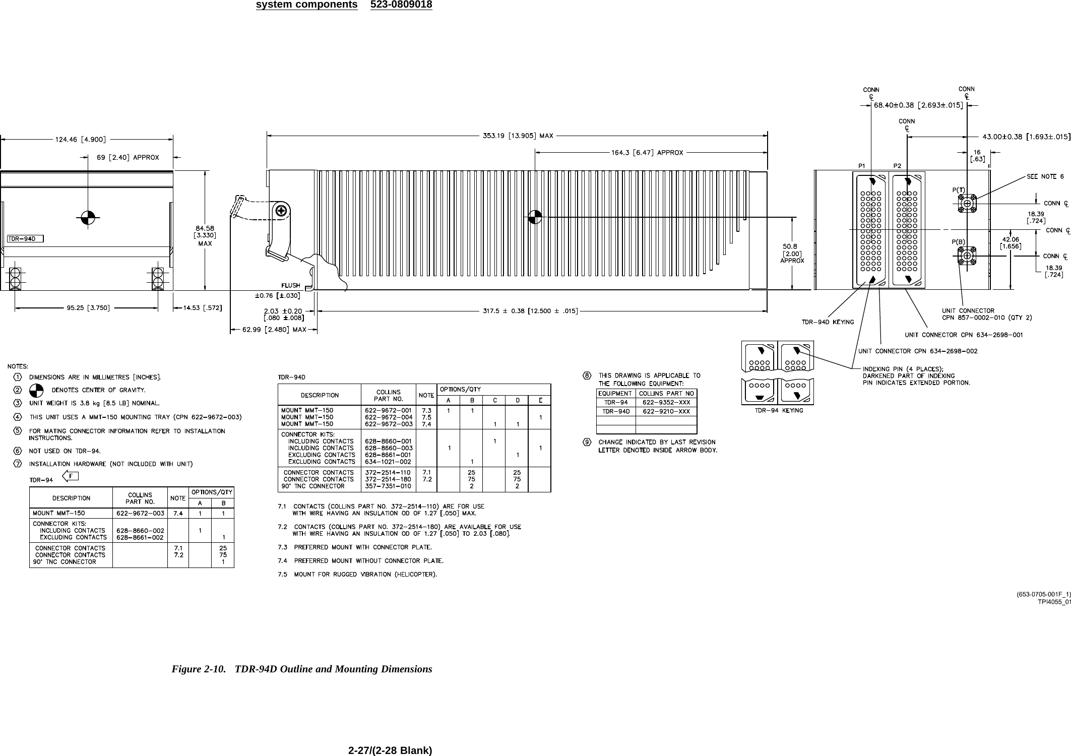
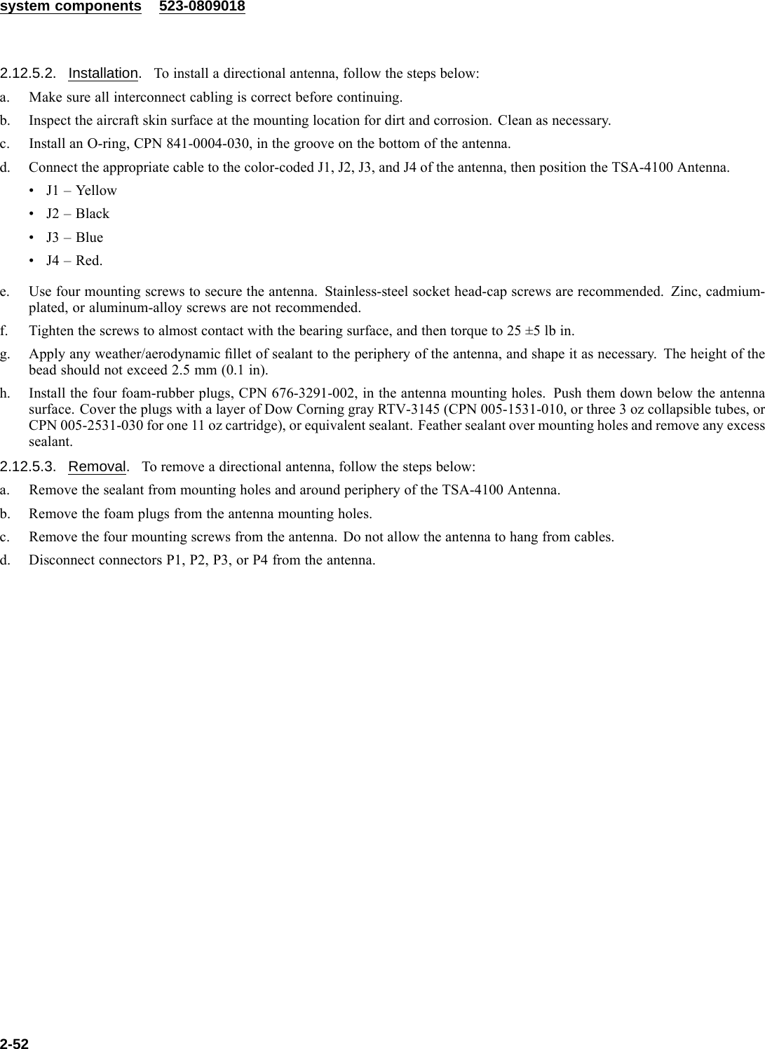
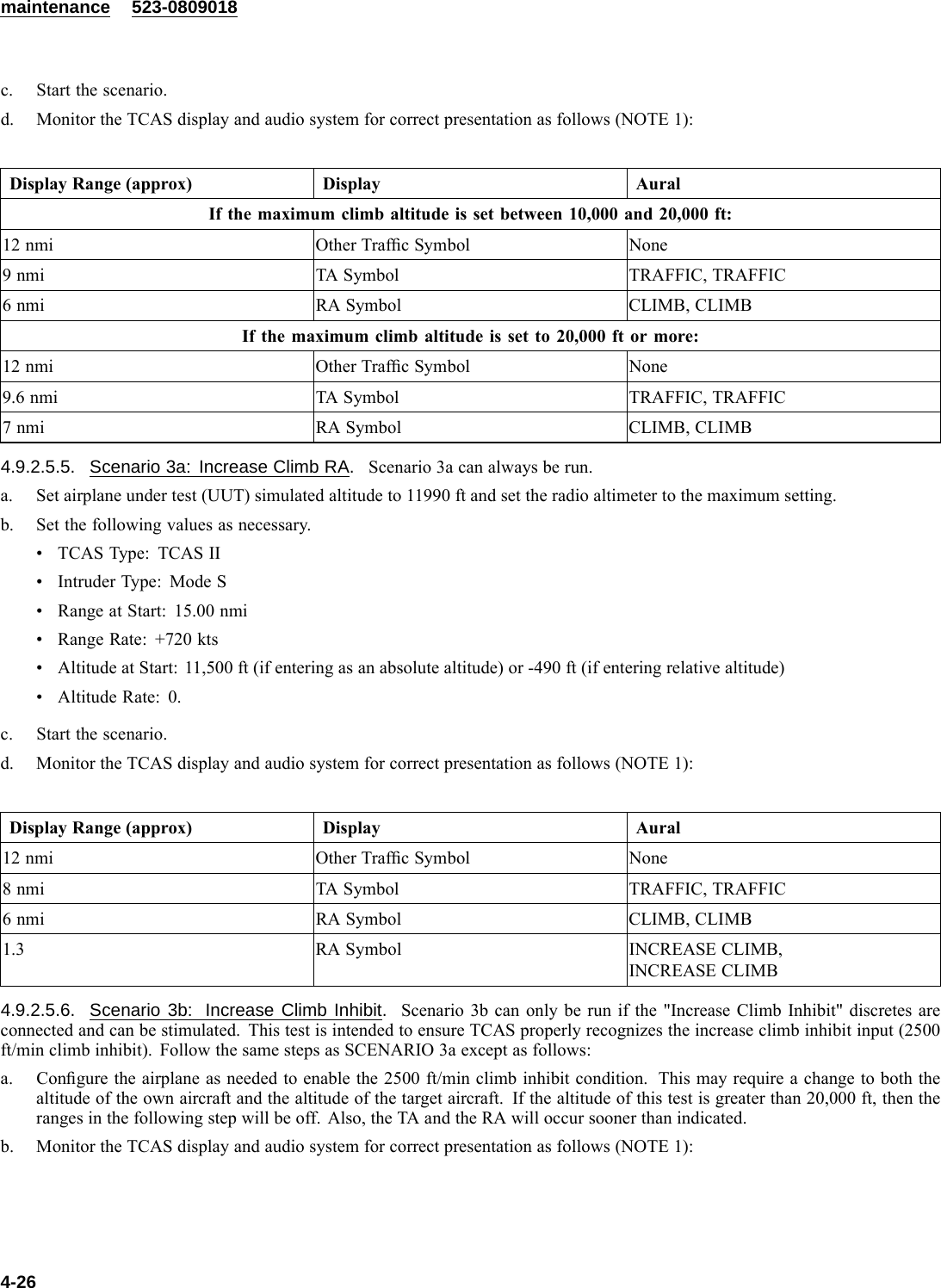
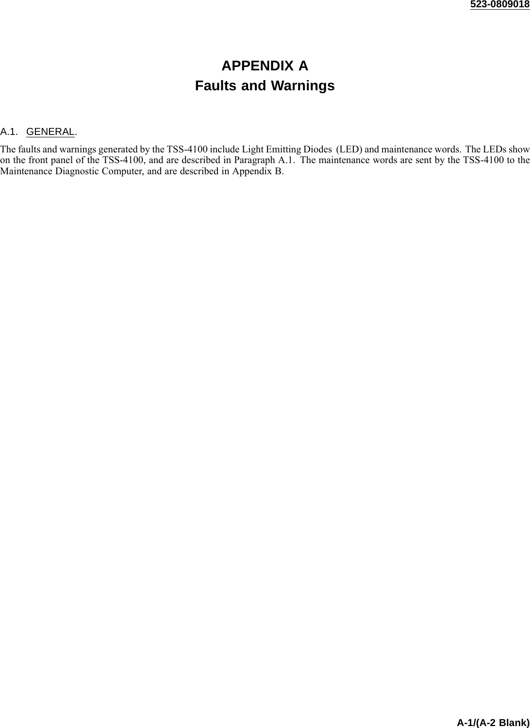
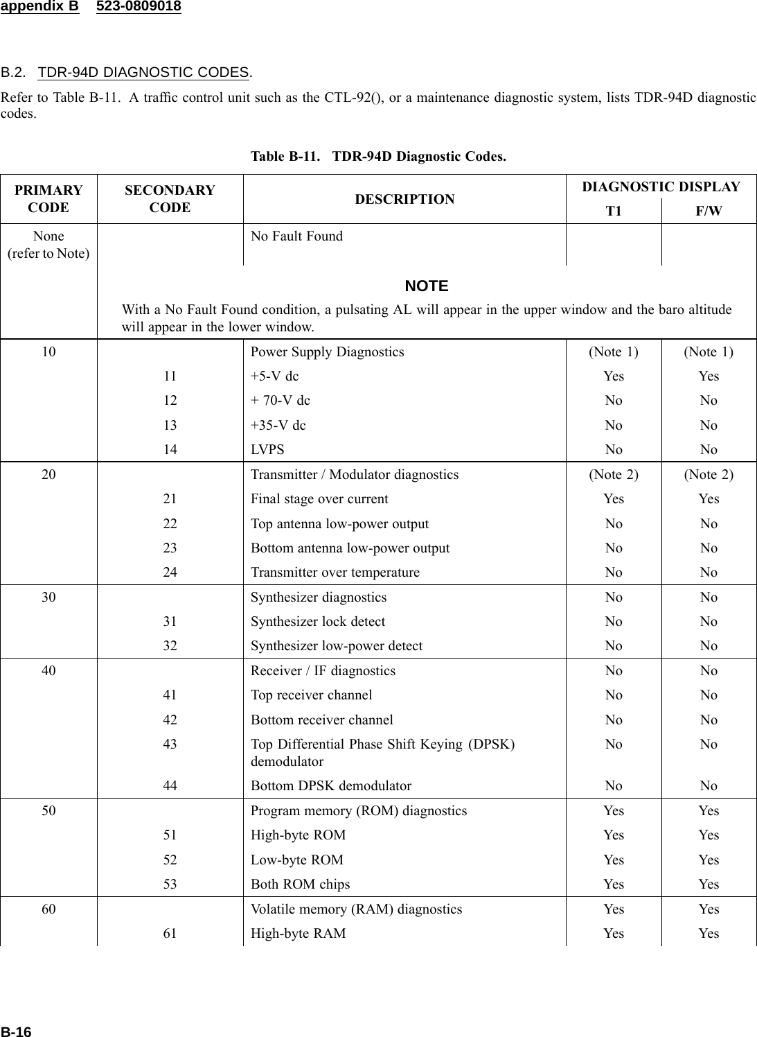
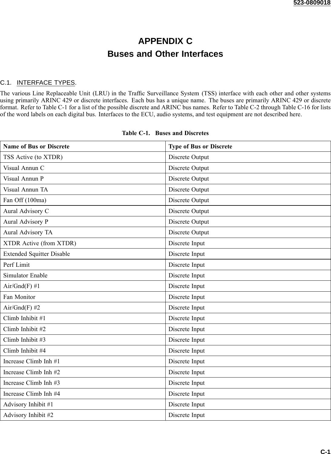
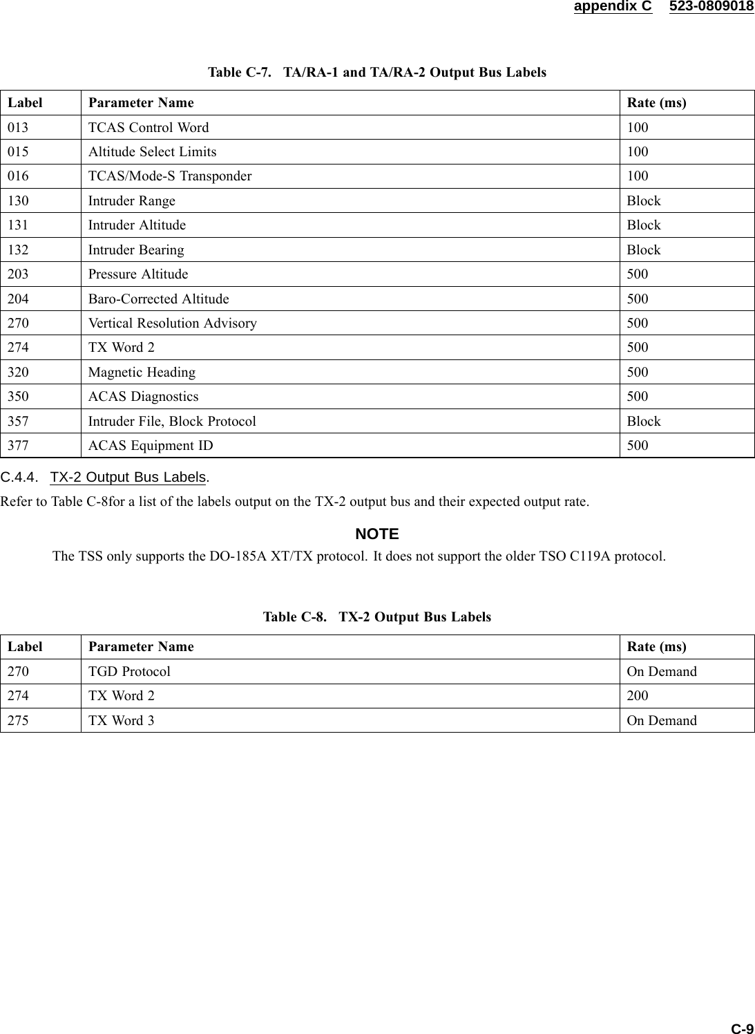
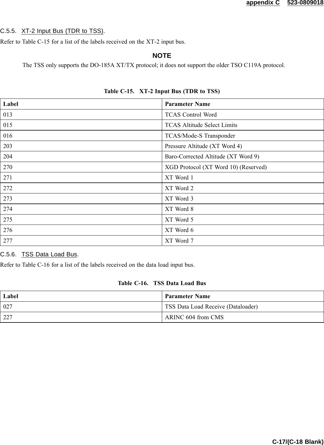
![appendix D 523-0809018Table D-8. TSS-4100 Environmental Qualification Form.CONDITIONS DO-160E SECTIONAND REVEQUIPMENT QUALIFICATIONSCATEGORIES OF CONDUCTED TESTSTemperature and Altitude 4.0 [(F2)(A2)V]- Temperature- Low Temperature Storage F2- High Temperature Operation F2- High Temperature Storage F2- Low Temperature Operation F2- In-Flight Loss of Cooling V- Altitude F2- Decompression A2- Overpressure A2Temperature Variation 5.0 AHumidity 6.0 BShock 7.0 B- Operational- Crash SafetyVibration 8.0 Equipment Tested to Cat R curves BB1, Cat Scurves CLM andCatHcurveRExplosion 9.0 EWaterproofness 10.0 YFluids Susceptibility 11.0 XSand and Dust 12.0 XFungus 13.0 XSalt Spray 14.0 XMagnetic Effect 15.0 ZPower Input 16.0 ABVoltage Spike Conducted 17.0 AAudio Frequency Conducted Susceptibility 18.0 ZInduced Signal Susceptibility 19.0 CCRadio Frequency Susceptibility 20.0 RRRadio Frequency Emission 21.0 MLightning Induced Transient Susceptibility 22.0 (B3)(K3)3Lightning Direct Effects 23.0 XIcing 24.0 AElectrostatic Discharge 25.0 AFire/Flammability 26.0 XTCAS RF Characteristics NAD-9](https://usermanual.wiki/Rockwell-Collins/8222132.Manual-2/User-Guide-1135854-Page-203.png)