Rockwell Collins 8222132 Rockwell Collins TSS-4100 Integrated Surveillance System User Manual Manual 2
Rockwell Collins Inc Rockwell Collins TSS-4100 Integrated Surveillance System Manual 2
Contents
- 1. Manual 1
- 2. Manual 2
Manual 2

installation
manual
TSS-4100 Integrated TCAS,
Transponder, and ADS-B Traffic
Surveillance System
Export Control Classification Notice (ECCN) for this document is 6E991.
©Co
pyright 2009 Rockwell Collins, Inc. All rights reserved.

TSS-4100 Integrated TCAS,
Transponder, and ADS-B Traffic
Surveillance System
installation manual
Printed in the United States of America Rockwell Collins, Inc.
© Copyright 2009 Rockwell Collins, Inc. All Rights Reserved. Cedar Rapids, Iowa 52498
(_TSS-4100_IM_MAY_29/2009_) 523-0809018-002116
1st Edition, 20 July 2007
2nd Edition, 29 May 2009
T-1
ROCKWELL COLLINS, INC.
INSTALLATION MANUAL
Export Control Classification Notice (ECCN) for this document is 6E991.
PROPRIETARY NOTICE
FREEDOM OF INFORMATION ACT (5 USC 552) AND DISCLOSURE OF CONFIDENTIAL INFORMATION
GENERALLY (18 USC 1905)
This document and the information disclosed herein are proprietary data of Rockwell Collins, Inc. Neither this
document nor the information contained herein shall be used, reproduced, or disclosed to others without the written
authorization of Rockwell Collins, Inc., except to the extent required for installation or maintenance of recipient’s
equipment. This document is being furnished in confidence by Rockwell Collins, Inc. The information disclosed
herein falls within the exemption (b) (4) of 5 USC 552 and the prohibitions of 18 USC 1905.
SOFTWARE COPYRIGHT NOTICE
© COPYRIGHT 2007-2009 ROCKWELL COLLINS, INC. ALL RIGHTS RESERVED
All software resident in this equipment is protected by copyright.
We welcome your comments concerning this manual. Although every effort has been made to keep it free of
errors, some may occur. When reporting a specific problem, please describe it briefly and include the manual part
number, the paragraph or figure number, and the page number.
Send your comments to: Rockwell Collins, Inc.
400 Collins Road NE, M/S 153-250
Cedar Rapids, IA 52498-0001
EMAIL: techmanuals@rockwellcollins.com
For product orders or inquiries, please contact: Rockwell Collins, Inc.
Customer Response Center
400 Collins Road NE, M/S 133-100
Cedar Rapids, IA 52498-0001
TELEPHONE: 1.888.265.5467
INTERNATIONAL: 1.319.265.5467
FAX NO: 319.295.4941
EMAIL: response@rockwellcollins.com
.
T-2

523-0809018
INSERT LATEST CHANGED PAGES. DESTROY SUPERSEDED PAGES.
LIST OF EFFECTIVE PAGES
NOTE: The portion of the text affected by the changes is indicated by a vertical line
in the outer margins of the page. Changes to illustrations are indicated by
shaded or screened areas, or by miniature pointing hands.
Dates of issue for original and changed pages are:
Original0 ........... 29May2009
TOTAL NUMBER OF PAGES IN THIS PUBLICATION IS 210 CONSISTING OF THE FOLLOWING:
Page *Change Page *Change Page *Change
No. No. No. No. No. No.
T-1-T-2 .......................0
A .............................0
BBlank........................0
i-vii ..........................0
viiiBlank.......................0
ix-xi..........................0
xiiBlank .......................0
xiii ............................0
xivBlank.......................0
1-1-1-5 .......................0
1-6Blank.......................0
1-7 ............................0
1-8Blank.......................0
1-9 ............................0
1-10Blank......................0
2-1-2-5 .......................0
2-6Blank.......................0
2-7 ............................0
2-8Blank.......................0
2-9-2-15 ......................0
2-16Blank......................0
2-17 ...........................0
2-18Blank......................0
2-19 ...........................0
2-20Blank......................0
2-21 ...........................0
2-22Blank......................0
2-23 ...........................0
2-24Blank......................0
2-25-2-27 .....................0
2-28Blank......................0
2-29-2-31 .....................0
2-32Blank......................0
2-33-2-35 .....................0
2-36Blank......................0
2-37 ...........................0
2-38Blank......................0
2-39 ...........................0
2-40Blank......................0
2-41 ...........................0
2-42Blank......................0
2-43 ...........................0
2-44Blank......................0
2-45 ...........................0
2-46Blank......................0
2-47 ...........................0
2-48Blank......................0
2-49-2-55 .....................0
2-56Blank......................0
2-57-2-65 .....................0
2-66Blank......................0
2-67 ...........................0
2-68Blank......................0
2-69 ...........................0
2-70Blank......................0
2-71 ...........................0
2-72Blank......................0
2-73 ...........................0
2-74Blank......................0
2-75 ...........................0
2-76Blank......................0
2-77-2-79 .....................0
2-80Blank......................0
3-1-3-14 ......................0
4-1-4-29 ......................0
4-30Blank......................0
A-1 ...........................0
A-2Blank ......................0
B-1-B-19 .....................0
B-20Blank .....................0
C-1-C-17 .....................0
C-18Blank .....................0
D-1-D-10 .....................0
E-1-E-3 .......................0
E-4Blank ......................0
E-5 ............................0
E-6Blank ......................0
E-7 ............................0
E-8Blank ......................0
*Zero in this column indicates an original page.
A/(B Blank)

523-0809018
TABLE OF CONTENTS
Chapter/Para Page
LISTOFILLUSTRATIONS .................................................................................... v
LISTOFTABLES.............................................................................................vi
INTRODUCTION .............................................................................................ix
SAFETYSUMMARY........................................................................................ xiii
1 GeneralInformation.......................................................................................... 1-1
1.1 INTRODUCTION. . . . . . . . . . . . . . . . . . . . . . . . . . . . . . . . . . . . . . . . . . . . . . . . . . . . . . . . . . . . . . . . . . . . . . . . . . . . . . . . . . . 1-1
1.2 EQUIPMENT........................................................................................ 1-1
1.2.1 EquipmentCovered. ................................................................................. 1-1
1.3 SYSTEMOVERVIEW. .............................................................................. 1-4
1.3.1 SystemBlockDiagram................................................................................ 1-4
1.4 COMPONENTDESCRIPTIONS. ..................................................................... 1-9
1.4.1 TSS-4100 Traffic Surveillance System. . . . . . . . . . . . . . . . . . . . . . . . . . . . . . . . . . . . . . . . . . . . . . . . . . . . . . . . . . . . . . . . . . 1-9
1.4.2 ECU-3000ExternalCompensationUnit................................................................. 1-9
1.4.3 TDR-94DATC/ModeSTransponder. .................................................................. 1-9
1.4.4 TSA-4100DirectionalAntenna. ....................................................................... 1-9
1.4.5 TRE-930OmnidirectionalAntenna..................................................................... 1-9
1.4.6 ANT-42OmnidirectionalAntenna...................................................................... 1-9
1.4.7 TSM-4100 Traffic Surveillance Mount. . . . . . . . . . . . . . . . . . . . . . . . . . . . . . . . . . . . . . . . . . . . . . . . . . . . . . . . . . . . . . . . . . 1-9
2 SystemComponents.......................................................................................... 2-1
2.1 INTRODUCTION. . . . . . . . . . . . . . . . . . . . . . . . . . . . . . . . . . . . . . . . . . . . . . . . . . . . . . . . . . . . . . . . . . . . . . . . . . . . . . . . . . . 2-1
2.1.1 LRUSystemSection.................................................................................. 2-1
2.1.2 LRUDataSection.................................................................................... 2-1
2.2 COMPONENTDESCRIPTIONS. ..................................................................... 2-1
2.2.1 ANT-42ModeSL-BandAntenna...................................................................... 2-1
2.2.2 TDR-94DATC/ModeSTransponder. .................................................................. 2-1
2.2.3 TRE-930ModeSOmnidirectionalAntenna. ............................................................ 2-2
2.2.4 TSA-4100ModeSDirectionalAntenna................................................................. 2-2
2.2.5 TSS-4100 Traffic Surveillance System. . . . . . . . . . . . . . . . . . . . . . . . . . . . . . . . . . . . . . . . . . . . . . . . . . . . . . . . . . . . . . . . . . 2-2
2.3 ANT-4234-54-00.................................................................................... 2-3
2.3.1 ANT-42,ExternalTheoryofOperation. ................................................................ 2-3
2.4 L-BANDANTENNA,ANT-42,DATA................................................................. 2-3
2.4.1 ANT-42Illustration. ................................................................................. 2-3
2.4.2 ANT-42MatingConnectorData. ...................................................................... 2-3
2.4.3 ANT-42OutlineandMountingDimensions. ............................................................ 2-4
2.4.4 InstallationandRemoval.............................................................................. 2-7
2.5 ECU-300034-54-00.................................................................................. 2-9
2.5.1 ExternalControlUnit,ExternalTheoryofOperation. .................................................... 2-9
2.6 EXTERNALCONTROLUNIT,ECU-3000,DATA. .................................................... 2-9
2.6.1 ECUTopHalf. ...................................................................................... 2-9
2.6.2 ECUBottomHalf,FirstPartition....................................................................... 2-9
2.6.3 ECU Bottom Half, Second Partition. . . . . . . . . . . . . . . . . . . . . . . . . . . . . . . . . . . . . . . . . . . . . . . . . . . . . . . . . . . . . . . . . . . . 2-9
2.6.4 ECU-3000Illustration. .............................................................................. 2-14
2.6.5 ECU-3000MatingConnectorData.................................................................... 2-14
2.6.6 ECU-3000OutlineandMountingDimensions.......................................................... 2-15
2.6.7 InstallationandRemoval............................................................................. 2-19
2.6.8 InternalTheoryofOperation.......................................................................... 2-19
2.7 TDR-94D34-54-00.................................................................................. 2-21
2.7.1 ModeSTransponder,ExternalTheoryofOperation. .................................................... 2-21
i

523-0809018
TABLE OF CONTENTS
Chapter/Para Page
2.8 MODE S TRANSPONDER, TDR-94D, DATA. . . . . . . . . . . . . . . . . . . . . . . . . . . . . . . . . . . . . . . . . . . . . . . . . . . . . . . . . 2-25
2.8.1 TDR-94DATC/ModeSTransponderMountingConsiderations........................................... 2-25
2.8.2 TDR-94DIllustration................................................................................ 2-25
2.8.3 TDR-94DMatingConnectorData..................................................................... 2-25
2.8.4 TDR-94DOutlineandMountingDimensions........................................................... 2-26
2.8.5 InstallationandRemoval............................................................................. 2-29
2.8.6 InternalTheoryofOperation.......................................................................... 2-29
2.9 TRE-93034-54-00. ................................................................................. 2-33
2.9.1 TRE-930L-BandDirectionalAntenna,ExternalTheoryofOperation...................................... 2-33
2.10 ANTENNA, TRE-930, DATA. . . . . . . . . . . . . . . . . . . . . . . . . . . . . . . . . . . . . . . . . . . . . . . . . . . . . . . . . . . . . . . . . . . . . . . . 2-33
2.10.1 TRE-930Illustration................................................................................. 2-33
2.10.2 TRE-930MatingConnectorData. .................................................................... 2-34
2.10.3 TRE-930 Outline and Mounting Dimensions.. . . . . . . . . . . . . . . . . . . . . . . . . . . . . . . . . . . . . . . . . . . . . . . . . . . . . . . . . . . 2-34
2.10.4 Omni-DirectionalRequirements....................................................................... 2-37
2.10.5 InstallationandRemoval............................................................................. 2-37
2.11 TSA-410034-54-00. ................................................................................ 2-39
2.11.1 Traffic Surveillance Antenna, External Theory of Operation. . . . . . . . . . . . . . . . . . . . . . . . . . . . . . . . . . . . . . . . . . . . . . 2-39
2.12 ANTENNA, TSA-4100, DATA. . . . . . . . . . . . . . . . . . . . . . . . . . . . . . . . . . . . . . . . . . . . . . . . . . . . . . . . . . . . . . . . . . . . . . . 2-39
2.12.1 TSA-4100Illustration................................................................................ 2-39
2.12.2 TSA-4100OutlineandMountingDiagram. ............................................................ 2-39
2.12.3 TSA-4100MatingConnectorData. ................................................................... 2-49
2.12.4 CablingConsiderations. ............................................................................. 2-49
2.12.5 InstallationandRemoval............................................................................. 2-49
2.13 TSS-410034-43-00.................................................................................. 2-53
2.13.1 Traffic Surveillance System, External Theory of Operation. . . . . . . . . . . . . . . . . . . . . . . . . . . . . . . . . . . . . . . . . . . . . . . 2-53
2.14 TRAFFICSURVEILLANCESYSTEM,TSS-4100,DATA............................................... 2-57
2.14.1 TSS-4100AntennaRequirements. .................................................................... 2-57
2.14.2 TSS-4100andTSM-4100Illustration.................................................................. 2-57
2.14.3 TSS-4100MatingConnectorData..................................................................... 2-58
2.14.4 TSS-4100OutlineandMountingDimensions........................................................... 2-64
2.14.5 CablingConsiderations. ............................................................................. 2-77
2.14.6 InstallationandRemoval............................................................................. 2-77
2.14.7 InternalTheoryofOperation.......................................................................... 2-77
3 Operation ................................................................................................... 3-1
3.1 INTRODUCTION. .................................................................................. 3-1
3.2 GENERAL.......................................................................................... 3-1
4 Maintenance................................................................................................. 4-1
4.1 INTRODUCTION. .................................................................................. 4-1
4.1.1 FlightLineMaintenance. ............................................................................. 4-1
4.1.2 AutomaticTesting.................................................................................... 4-1
4.2 MAINTENANCE SCHEDULE. . . . . . . . . . . . . . . . . . . . . . . . . . . . . . . . . . . . . . . . . . . . . . . . . . . . . . . . . . . . . . . . . . . . . . . . 4-2
4.2.1 CleaningandPainting................................................................................. 4-2
4.2.2 CleaningIndicators................................................................................... 4-2
4.2.3 CleaningAntennas. .................................................................................. 4-2
4.2.4 ApprovedRepairs.................................................................................... 4-2
4.3 CONVERSIONFROMTTR/TDRTOTSSSYSTEM.................................................... 4-3
4.3.1 PreparationforConversion............................................................................ 4-3
4.3.2 DifferencesbetweenTTR/TDRandTSS................................................................ 4-3
4.4 DATALOADING.................................................................................... 4-4
4.4.1 ECUData........................................................................................... 4-4
4.4.2 TSSDataLoading.................................................................................... 4-4
4.4.3 TSSElectronicNameplate............................................................................. 4-5
ii

523-0809018
TABLE OF CONTENTS
Chapter/Para Page
4.5 TSS-4100 MODE S ADDRESS PROGRAMMING TOOL. . . . . . . . . . . . . . . . . . . . . . . . . . . . . . . . . . . . . . . . . . . . . . . . 4-6
4.5.1 ProgrammingToolSupport............................................................................ 4-6
4.5.2 ProgrammingToolSystemRequirements. .............................................................. 4-6
4.5.3 ProgrammingToolInstallation......................................................................... 4-7
4.5.4 ProgrammingToolSetup.............................................................................. 4-7
4.5.5 ProgrammingToolInstructions. ....................................................................... 4-9
4.5.6 ProgrammingToolOverview. ........................................................................ 4-10
4.6 LEDINDICATORS. ................................................................................ 4-11
4.6.1 LEDDescriptions. .................................................................................. 4-11
4.7 TESTEQUIPMENTANDPOWERREQUIREMENTS................................................. 4-14
4.7.1 PowerRequirements................................................................................. 4-14
4.8 TESTINGANDTROUBLESHOOTING. ............................................................. 4-15
4.8.1 Pre-installationTesting............................................................................... 4-15
4.8.2 TCASSelfTest. .................................................................................... 4-15
4.8.3 EquipmentSetup.................................................................................... 4-16
4.8.4 Radio Altitude System Failure Tests. . . . . . . . . . . . . . . . . . . . . . . . . . . . . . . . . . . . . . . . . . . . . . . . . . . . . . . . . . . . . . . . . . . 4-16
4.8.5 Pressure Altitude System Failure Tests. . . . . . . . . . . . . . . . . . . . . . . . . . . . . . . . . . . . . . . . . . . . . . . . . . . . . . . . . . . . . . . . . 4-17
4.8.6 RangeandBearingTest.............................................................................. 4-18
4.8.7 TCASRATest...................................................................................... 4-19
4.8.8 TransponderTests................................................................................... 4-19
4.8.9 ADS-BTransmitGroundTest......................................................................... 4-20
4.8.10 Transponder/TCASSuppressionBusIssues. ........................................................... 4-20
4.9 INITIALINSTALLATIONCHECKOUTPROCEDURE................................................ 4-22
4.9.1 Initial Transponder Check Out. . . . . . . . . . . . . . . . . . . . . . . . . . . . . . . . . . . . . . . . . . . . . . . . . . . . . . . . . . . . . . . . . . . . . . . . 4-22
4.9.2 Initial TCAS Check Out.. . . . . . . . . . . . . . . . . . . . . . . . . . . . . . . . . . . . . . . . . . . . . . . . . . . . . . . . . . . . . . . . . . . . . . . . . . . . . 4-22
4.10 RETURNTOSERVICETESTPROCEDURE.......................................................... 4-29
4.10.1 ReturntoServiceTest. .............................................................................. 4-29
4.11 INSPECTION/CHECK. ............................................................................. 4-29
4.11.1 Antennas........................................................................................... 4-29
4.11.2 TSS-4100 Traffic Surveillance System. . . . . . . . . . . . . . . . . . . . . . . . . . . . . . . . . . . . . . . . . . . . . . . . . . . . . . . . . . . . . . . . . 4-29
4.11.3 TDR-94DATC/ModeSTransponder. ................................................................. 4-29
AppendixAFaultsandWarnings...................................................................................A-1
A.1 GENERAL...........................................................................................A-1
AppendixBMaintenanceWords....................................................................................B-1
B.1 MAINTENANCEDIAGNOSTICWORDS..............................................................B-1
B.1.1 Label350TDRMaintenanceWord.....................................................................B-4
B.1.2 Label351TSS-4100DiagnosticWord1. ...............................................................B-4
B.1.3 Label352CDUDiagnosticWord1.....................................................................B-5
B.1.4 Label353TSS-4100DiagnosticWord2. ...............................................................B-5
B.1.5 Label354TSS-4100DiagnosticWord3. ..............................................................B-11
B.1.6 Label355TSS-4100DiagnosticWord4. ..............................................................B-12
B.1.7 Label350ACASDiagnostics.........................................................................B-14
B.2 TDR-94DDIAGNOSTICCODES.....................................................................B-16
Appendix C Buses and Other Interfaces. . . . . . . . . . . . . . . . . . . . . . . . . . . . . . . . . . . . . . . . . . . . . . . . . . . . . . . . . . . . . . . . . . . . . . . . . . . . . . C-1
C.1 INTERFACETYPES..................................................................................C-1
C.2 TSSDISCRETEOUTPUTS. ..........................................................................C-4
C.3 TSSDISCRETEINPUTS..............................................................................C-5
C.4 TSSA429OUTPUTBUSES...........................................................................C-7
C.4.1 TSS-1andTSS-2OutputBusLabels. ..................................................................C-7
C.4.2 TSS-3OutputBusLabels. ............................................................................C-8
C.4.3 TA/RA-1andTA/RA-2OutputBusLabels..............................................................C-8
C.4.4 TX-2OutputBusLabels. .............................................................................C-9
iii

523-0809018
TABLE OF CONTENTS
Chapter/Para Page
C.5 A429INPUTBUSES. ...............................................................................C-10
C.5.1 ControlBusSelection................................................................................C-10
C.5.2 ControlBusLabels..................................................................................C-10
C.5.3 ConcentratedBusInputs. ............................................................................C-11
C.5.4 GPSInputData. ....................................................................................C-14
C.5.5 XT-2InputBus(TDRtoTSS)........................................................................C-17
C.5.6 TSSDataLoadBus..................................................................................C-17
AppendixDEquipmentCharacteristics..............................................................................D-1
D.1 EQUIPMENTCHARACTERISTICS. ..................................................................D-1
AppendixEInterconnectDiagram .................................................................................. E-1
E.1 INTRODUCTION....................................................................................E-1
E.2 CABLINGINSTRUCTIONS. .........................................................................E-1
E.3 GROUNDING AND HIRF GUIDELINES.. . . . . . . . . . . . . . . . . . . . . . . . . . . . . . . . . . . . . . . . . . . . . . . . . . . . . . . . . . . . . . E-1
E.4 SYSTEMINTERCONNECTDIAGRAM. .............................................................. E-2
iv

523-0809018
LIST OF ILLUSTRATIONS
Number Title Page
1-1 Typical Single TrafficSurveillanceSystem ................................................................... 1-3
1-2 Typical TrafficSurveillanceSystemwithRIUs,BlockDiagram................................................. 1-5
1-3 Typical TrafficSurveillanceSystemwithoutRIUs,BlockDiagram .............................................. 1-7
2-1 ANT-42.................................................................................................. 2-3
2-2 ANT-42L-BandAntenna,OutlineandMountingDimensions .................................................. 2-5
2-3 External Compensation Unit, ECU-3000, External SimplifiedSchematic......................................... 2-9
2-4 ECU-3000............................................................................................... 2-14
2-5 ECU-3000MatingConnectors............................................................................. 2-15
2-6 ECU-3000 Outline and Mounting Dimensions . . . . . . . . . . . . . . . . . . . . . . . . . . . . . . . . . . . . . . . . . . . . . . . . . . . . . . . . . . . . . . . 2-17
2-7 ModeSTransponder,TDR-94D,ExternalTheoryofOperation ................................................ 2-23
2-8 TDR-94D ............................................................................................... 2-25
2-9 TDR-94DMatingConnectors.............................................................................. 2-26
2-10 TDR-94D Outline and Mounting Dimensions . . . . . . . . . . . . . . . . . . . . . . . . . . . . . . . . . . . . . . . . . . . . . . . . . . . . . . . . . . . . . . . . 2-27
2-11 ModeSTransponder,TDR-94D,InternalTheoryofOperation................................................. 2-31
2-12 TRE-930................................................................................................ 2-33
2-13 TRE-930L-BandAntenna,OutlineandMountingDimensions................................................. 2-35
2-14 TSA-4100,ShortandLongConnectors ..................................................................... 2-39
2-15 TSA-4100 Outline and Mounting Diagram, Long Connector Version . . . . . . . . . . . . . . . . . . . . . . . . . . . . . . . . . . . . . . . . . . . 2-41
2-16 TSA-4100 Outline and Mounting Diagram, Short Connector Version . . . . . . . . . . . . . . . . . . . . . . . . . . . . . . . . . . . . . . . . . . . 2-45
2-17 TCASDirectionalAntenna,MountingDiagram.............................................................. 2-51
2-18 Traffic Surveillance System, External Block Diagram . . . . . . . . . . . . . . . . . . . . . . . . . . . . . . . . . . . . . . . . . . . . . . . . . . . . . . . . . 2-54
2-19 Traffic Surveillance System, TSS-4100 No. 1, External SimplifiedSchematic.................................... 2-55
2-20 TSS-4100 ............................................................................................... 2-57
2-21 TSM-4100............................................................................................... 2-58
2-22 TSS-4100MatingConnectors.............................................................................. 2-60
2-23 TSS-4100 Traffic Surveillance System, Outline and Mounting Dimensions . . . . . . . . . . . . . . . . . . . . . . . . . . . . . . . . . . . . . . 2-65
2-24 TSM-4100 TrafficSurveillanceMount,Outline .............................................................. 2-71
2-25 Traffic Surveillance System, TSS-4100, Internal Block Diagram . . . . . . . . . . . . . . . . . . . . . . . . . . . . . . . . . . . . . . . . . . . . . . . 2-79
3-1 TrafficDisplay(AFD-3010/3010E),TRAFFICPage........................................................... 3-2
3-2 ResolutionAdvisoryDisplay(AFD),TCASIIFly-ToCommands............................................... 3-5
3-3 ResolutionAdvisoryDisplay(AFD),PitchCues .............................................................. 3-6
3-4 TopLevelRadioTuningPage,RTU-42XXRadioTuningUnit.................................................. 3-8
3-5 TopLevelRadioTunePage,CDU-62XXControlDisplayUnit ................................................. 3-8
3-6 TCASPage,RadioTuningUnit(RTU-42XX) ............................................................... 3-10
3-7 TCASPage,ControlDisplayUnit(CDU-62XX)............................................................. 3-10
3-8 TransponderPage,RTU-42XXRadioTuningUnit ........................................................... 3-13
3-9 TransponderPage,CDU-62XXControlDisplayUnit......................................................... 3-13
4-1 TSS-4100,ElectronicNameplate............................................................................ 4-6
4-2 ProgrammingTool-SelectNetworkInterfaceCard............................................................ 4-8
4-3 ProgrammingTool-ChangetheIPAddress .................................................................. 4-8
4-4 ProgrammingTool-UnlocktheIPAddress................................................................... 4-9
4-5 ProgrammingTool-VerifytheIPAddress.................................................................... 4-9
4-6 ProgrammingTool-ScreenShot........................................................................... 4-11
4-7 TSS-4100FrontPanelLEDs............................................................................... 4-12
4-8 TCASSelfTestStandardOutput........................................................................... 4-16
4-9 BearingTest,AircraftandTCASTestSetOrientation......................................................... 4-19
4-10 SimplifiedFlightScenarioandParameters................................................................... 4-22
C-1 BusArchitecture,TSS(R)andTDR(L).....................................................................C-12
C-2 DualGPSInstallation.....................................................................................C-16
E-1 Traffic Surveillance System, Interconnect Wiring Diagram . . . . . . . . . . . . . . . . . . . . . . . . . . . . . . . . . . . . . . . . . . . . . . . . . . . . . E-3
v

523-0809018
LIST OF TABLES
Number Title Page
1-1 EquipmentCovered........................................................................................ 1-1
1-2 AssociatedEquipment...................................................................................... 1-2
2-1 ANT-42MatingConnectorHardwareandTooling............................................................. 2-4
2-2 ECUInstallationStrappingData............................................................................ 2-10
2-3 ECU-3000MatingConnectorHardwareandTooling.......................................................... 2-14
2-4 TDR-94DMatingConnectorHardwareandTooling........................................................... 2-25
2-5 TRE-930MatingConnectorHardwareandTooling. .......................................................... 2-34
2-6 TSA-4100MatingConnectorHardwareandTooling.......................................................... 2-49
2-7 TSS-4100MatingConnectorHardwareandTooling........................................................... 2-58
2-8 TSS-4100MatingConnectorPinsandFunctions,Power,Ground,Suppression................................... 2-60
2-9 TSS-4100MatingConnectorPinsandFunctions,ARINC429Input. ........................................... 2-61
2-10 TSS-4100MatingConnectorPinsandFunctions,ARINC429Output........................................... 2-61
2-11 TSS-4100MatingConnectorPinsandFunctions,GPSTimeMarkInput......................................... 2-62
2-12 TSS-4100MatingConnectorPinsandFunctions,DiscreteInput(Gnd=Active).................................. 2-62
2-13 TSS-4100MatingConnectorPinsandFunctions,DiscreteOutput(Gnd=Active)................................ 2-63
2-14 TSS-4100MatingConnectorPinsandFunctions,AudioOutput................................................ 2-64
2-15 TSS-4100 Mating Connector Pins and Functions, ECU Interface.. . . . . . . . . . . . . . . . . . . . . . . . . . . . . . . . . . . . . . . . . . . . . . . 2-64
3-1 TrafficDisplay(AFD-3010/3010E),TRAFFICPage. .......................................................... 3-3
3-2 ResolutionAdvisoryDisplay(AFD),TCASIIFly-ToCommandsandPitchCues. ................................ 3-6
3-3 TopLevelRadioTunePage,RTURadioTuningUnitorCDUControlDisplayUnit. .............................. 3-9
3-4 TCASPage,RadioTuningUnitorControlDisplayUnit....................................................... 3-11
3-5 TransponderPage,RTURadioTuningUnitorControlDisplayUnit. ........................................... 3-13
4-1 DataLoadBusesAndPins ................................................................................. 4-4
4-2 ARINC615DataLoaders................................................................................... 4-5
4-3 LEDDescriptions ........................................................................................ 4-12
B-1 LRUDiagnosticData,ReportingLRUs......................................................................B-1
B-2 DiagnosticWordInterpretation..............................................................................B-2
B-3 HexadecimaltoBinaryConversionTable.....................................................................B-3
B-4 Label351TSS-4100DiagnosticWord1......................................................................B-4
B-5 Label353TSS-4100DiagnosticWord2......................................................................B-5
B-6 LRUDiagnosticData,FaultNamesandCategories. ...........................................................B-6
B-7 Label354TSS-4100DiagnosticWord3.....................................................................B-11
B-8 Label355TSS-4100DiagnosticWord4.....................................................................B-12
B-9 Label355VoltageDecode.................................................................................B-13
B-10 Label350ACASDiagnosticsWord ........................................................................B-14
B-11 TDR-94DDiagnosticCodes................................................................................B-16
C-1 BusesandDiscretes .......................................................................................C-1
C-2 TSSDiscreteOutputs......................................................................................C-4
C-3 TSSDiscreteInputs .......................................................................................C-5
C-4 TSSA429OutputBuses ...................................................................................C-7
C-5 TSS-1andTSS-2OutputBusLabels ........................................................................C-7
C-6 TSS-3OutputBusLabels ..................................................................................C-8
C-7 TA/RA-1andTA/RA-2OutputBusLabels...................................................................C-9
C-8 TX-2OutputBusLabels ...................................................................................C-9
C-9 A429InputBuses ........................................................................................C-10
C-10 ControlBusSelection.....................................................................................C-10
C-11 ControlBusLabels.......................................................................................C-11
C-12 ConcentratedBusInputs ..................................................................................C-12
C-13 GPSBusLabels..........................................................................................C-14
C-14 GPSData/TimeMarkInputCorrelation.....................................................................C-15
C-15 XT-2InputBus(TDRtoTSS).............................................................................C-17
C-16 TSSDataLoadBus.......................................................................................C-17
D-1 Equipment Specifications...................................................................................D-1
vi

523-0809018
LIST OF TABLES
Number Title Page
D-2 CertificationCategories.....................................................................................D-2
D-3 UnitWeight,PowerRequirements,andSize...................................................................D-2
D-4 ANT-42 Environmental QualificationForm...................................................................D-3
D-5 ECU-3000 Environmental QualificationForm.................................................................D-4
D-6 TDR-94D Environmental QualificationForm..................................................................D-6
D-7 TSA-4100 Environmental QualificationForm. ................................................................D-8
D-8 TSS-4100 Environmental QualificationForm..................................................................D-9
vii/(viii Blank)

523-0809018
INTRODUCTION
1. GENERAL.
This Installation Manual (IM) provides installation information regarding the TSS-4100 Traffic Surveillance System and its related
equipment.
2. HOW TO USE THE MANUAL.
This IM is written to Air Transport Association (ATA) Specification 100 standards and contains the chapters outlined below:
2.1. Chapter 1.
General Information chapter describes the purpose and technical properties of the Traffic Surveillance System LRUs.
2.2. Chapter 2.
System Components chapter describes each LRU separately and in detail. First the LRU is described as it relates to the rest of the
Traffic Surveillance System. Then the LRU is described as a stand alone piece of avionics equipment.
2.3. Chapter 3.
Operation chapter provides a description of the operating controls and displays that are available in the Traffic Surveillance System.
2.4. Chapter 4.
Maintenance chapter provides flight line maintenance instructions for the Traffic Surveillance System. This includes theory of op-
eration.
2.5. APPENDICES .
Appendices describe very detailed information about the avionics system.
1. APPENDIX A Faults and Warnings
2. APPENDIX B Maintenance Words
3. APPENDIX C Buses and Other Interfaces
4. APPENDIX D Equipment Characteristics
5. APPENDIX E Interconnect Diagram
3. ACRONYMS, ABBREVIATIONS, AND MNEMONICS.
The list that follows shows the abbreviations, acronyms, and mnemonics that are used in this publication to describe the avionics
system.
TERM MEANING
ABS Absolute
ACAS Airborne Collision Avoidance System
ADC Air Data Computer
ADLP Aircraft Data Link Processor (MODE-S)
ADS Air Data System
ADS-B Automatic Dependent Surveillance-Broadcast
AFD Adaptive Flight Display
AHC Attitude Heading Computer
ALT Altitude
ANT Antenna
ARINC Digital Database Protocols
AT C A i r Tr a fficControl
ATCRBS Air Traffic Control Radar Beacon System
ix

introduction 523-0809018
AUTO Automatic
BITE Built-In Test Equipment
BNR Binary
CDU Control Display Unit
CPN Collins Part Number
CRC Cyclic Redundancy Check
DCP Display Control Panel
DCU Data Concentrator Unit
DPSK Differential Phase Shift Keying
ECU External Compensation Unit
EFIS Electronic Flight Instrument System
ESDS Electrostatic Discharge Sensitive
FMS Flight Management System
GPS Global Positioning System
HAE Height Above Ellipsoid
HDG Heading
Hg Millimeters of Mercury
HIRF High Intensity Radiated Field
HSI Horizontal Situation Indicator
HV High-Voltage
IAPS Integrated Avionics Processor System
IRS Inertial Reference System
LRU Line Replaceable Unit
MCU Modular Concept Unit
MFD Multifunction Display
ms Millisecond
MSL Mean Sea Level
NA Not Applicable
NVRAM Non-Volatile RAM
PAM Pulse Amplitude Modulation
PFD Primary Flight Display
PPOS Present Position
RA TCAS Resolution Advisory
RAM Random Access Memory
REL Relative
RIU Radio Interface Unit
ROM Read Only Memory
RTU Radio Tuning Unit
SDI Source Destination Identifier
SLS Side-Lobe-Suppression
STBY Standby
STC Supplemental Type Certificate
TA Traffic Advisory
TBD To Be Determined
TC Type Certificate
TCAS Traffic Alert Collision Avoidance System
TDR Transponder
TFC Traffic
TRE TCAS II Directional Antenna
TSO Technical Standard Order
TSA Traffic Surveillance Antenna
TSS Traffic Surveillance System
TSSA Traffic Surveillance System Application
TSM Traffic Surveillance Mount
TTC TCAS Transponder Control
TX Transmit
x

introduction 523-0809018
To submit comments regarding this manual, please contact:
Rockwell Collins, Inc.
400 Collins Rd NE
Cedar Rapids, IA 52498-0001
Attn: Technical Operations M/S 153-250
or send email to: techmanuals@rockwellcollins.com
xi/(xii Blank)

523-0809018
SAFETY SUMMARY
1. GENERAL SAFETY INSTRUCTIONS.
This manual describes physical and chemical processes which may cause injury or death to personnel or damage to equipment if
not properly followed. This safety summary includes general safety precautions and instruction that must be understood and applied
during operation and maintenance to make sure personnel safety and protection of equipment. Prior to performing any task, the
WARNING, CAUTIONS, and NOTES included in that task shall be reviewed and understood.
2. WARNING, CAUTIONS AND NOTES.
WARNINGS and CAUTIONS are used in this manual to highlight operating or maintenance procedures, practices, conditions or
statements which are considered essential to protection of personnel (WARNING) or equipment (CAUTION). WARNINGS and
CAUTIONS immediately precede the step or procedure to which they apply. WARNINGS and CAUTIONS consist of four parts:
heading (WARNINGS, CAUTIONS or Icon [HAZARDOUS MATERIALS WARNING ]), a statement of the hazard, minimum
precautions, and possible result if disregarded. NOTES are used in this manual to highlight operating or maintenance procedures,
practices, conditions or statements which are not essential to protection of personnel or equipment. NOTES may precede or follow
the step or procedure, depending upon the information to be highlighted. The headings used and definitions are as follows.
Highlights an essential operating or maintenance procedure, practice, condition, or statement, etc. which if not
strictly observed, could result in injury to, or death of, personnel or long term health hazards.
Highlights an essential operating or maintenance procedure, practice, condition, or statement, etc. which if not
strictly observed, could result in damage to, or destruction of, equipment or loss of mission effectiveness.
NOTE
Highlights an essential operating or maintenance procedure, condition, or statement.
xiii/(xiv Blank)

523-0809018
CHAPTER 1
General Information
1.1. INTRODUCTION.
This publication provides all the specifications, principles of operation, and information necessary to install, test, and troubleshoot
the TSS-4100 Traffic Surveillance System (TSS). The three major functions of the TSS-4100 follow:
• The TSS-4100 is a Mode S transponder that replies to directed and all-call interrogations.
• The TSS-4100 is a Traffic Alert Collision Avoidance System (TCAS) II, change 7 unit. It monitors the area around the aircraft
for potential airspace conflicts.
• When enabled, the TSS-4100 is also an Automatic Dependent Surveillance-Broadcast (ADS-B) transmitter/receiver unit. It trans-
mits the aircraft position, velocity, and identification. It also processes the transmissions of other ADS-B equipped aircraft.
1.2. EQUIPMENT.
The Equipment Covered table shows the system avionics, mount, and avionics software. Associated equipment shows closely related
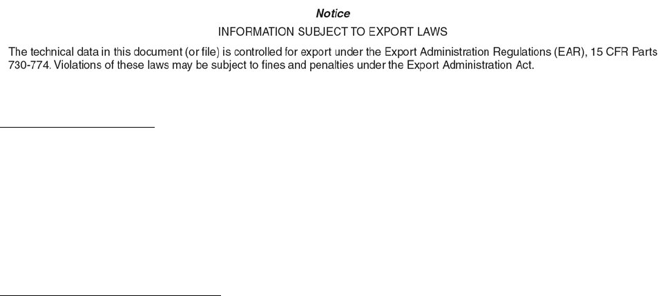
avionics. Refer to Figure 1-1 for the hardware of a typical single Traffic Surveillance System.
1.2.1. Equipment Covered.
Refer to Table 1-1 for a complete list of the Rockwell Collins avionics equipment covered in this manual.
Table 1-1. Equipment Covered.
UNIT DESCRIPTION COLLINS PART
NUMBER
STANDARD
QUANTITY
OPTIONAL
QUANTITY
TSS-4100 Traffic Surveillance System 822-2132-001 1
TSSA-4100 Traffic Surveillance System Application 810-0052-001 1
TSM-4100 Traffic Surveillance Mount 866-0128-020 1
ECU-3000 External Compensation Unit
-802: TCAS II, EHS Mode S Transponder
-803: TCAS II, EHS Mode S Transponder, ADS-B
Out
822-1200-80X 1
TSA-4100 Traffic Surveillance Antenna
-101: Baseline antenna; short connectors
-001: Optional replacement; long connectors
866-0016-X01 1 +1
TRE-930 Omnidirectional Antenna 866-5019-010 1 -1
1-1

general information 523-0809018
Table 1-2. Associated Equipment.
UNIT DESCRIPTION COLLINS PART
NUMBER
STANDARD
QUANTITY
OPTIONAL
QUANTITY
NOTE
Information for the TDR-94D and ANT-42 is for reference only. Refer to the Pro Line II Comm/Nav/Pulse System Instal-
lation Manual, Collins Part Number (CPN) 523-0772719.
TDR-94D Air Traffic Control Radar Beacon System (ATCRBS)
Mode S Transponder: -008, -108, -308, -309, -408,
or -409.
622-9210-X0X 1
ANT-42 Mode S omnidirectional antenna. Used with
TDR-94D.
622-6591-001 2
1.2.1.1. In addition to the Avionics, the TSS-4100 Mode S Address Programming Tool, CPN 811-3937-002, is covered in chapter
4 of this installation manual. This is used to program the Mode S Address for use by the TSS-4100.
1-2
general information 523-0809018
Figure 1-1. Typical Single Traffic Surveillance System
1-3

general information 523-0809018
1.3. SYSTEM OVERVIEW.
This section gives an overview of the Traffic Surveillance System.
1.3.1. System Block Diagram.
NOTE
Most units report maintenance information in a diagnostic word to the built-in diagnostic system. This section does
not refer to these diagnostic words. Refer to the maintenance section of this manual for diagnostic information.
The system schematics are not intended to replace bench level repair coverage. Component level coverage is
provided in the applicable repair manual.
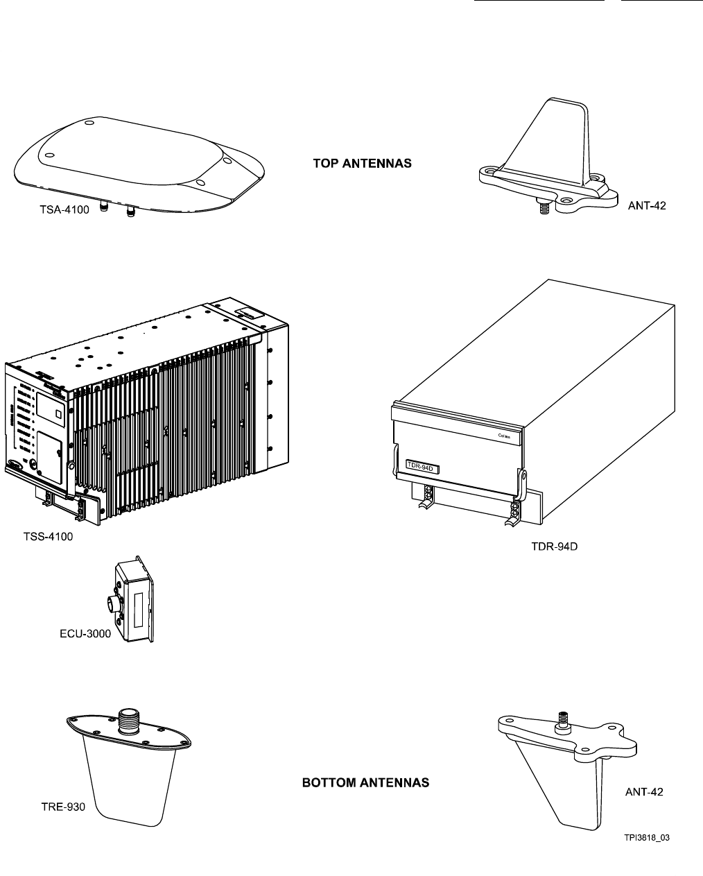
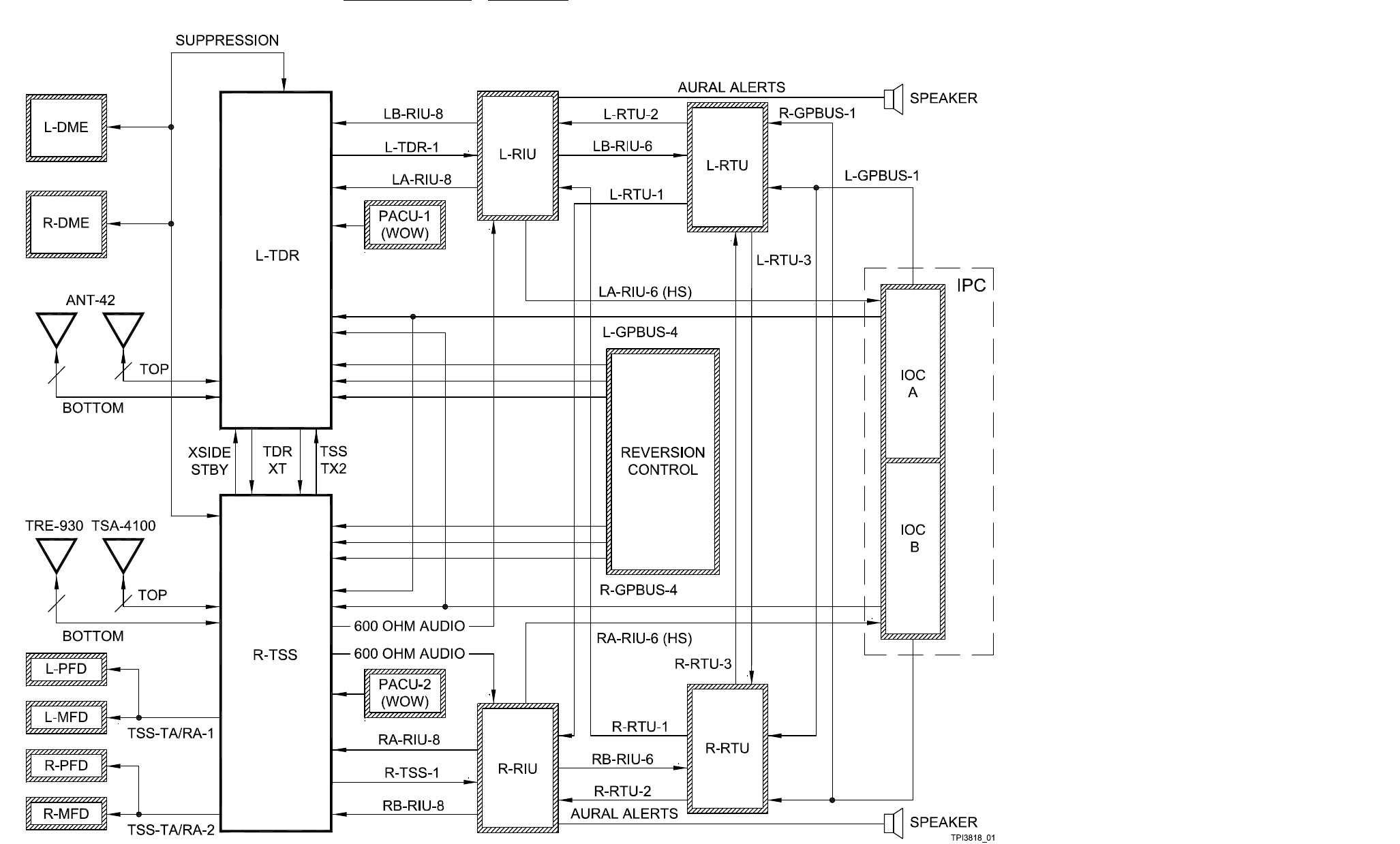
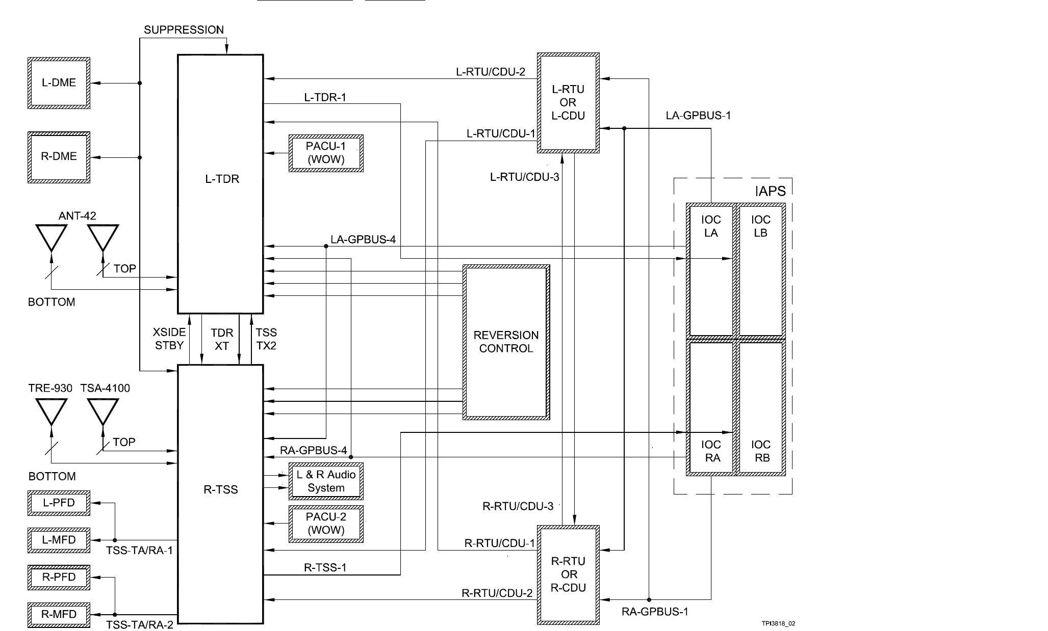
Refer to Figure 1-2 for a block diagram of a typical Traffic Surveillance System with Radio Interface Unit (RIU). Refer to Figure
1-3 for a block diagram of a typical Traffic Surveillance System without RIUs. Heavy solid-black borders identify all system units.
The slashed border outlines identify the interfacing units.
1-4
general information 523-0809018
Figure 1-2. Typical Traffic Surveillance System with RIUs, Block Diagram
1-5/(1-6 Blank)
general information 523-0809018
Figure 1-3. Typical Traffic Surveillance System without RIUs, Block Diagram
1-7/(1-8 Blank)

general information 523-0809018
1.4. COMPONENT DESCRIPTIONS.
The Traffic Surveillance System fully integrates with an airplane transponder and TCAS control system. The Traffic Surveillance
System includes the Line Replaceable Units (LRU) that follow:
• One TSS-4100 Traffic Surveillance System LRU
• TSSA-4100 Traffic Surveillance System Application (TSSA) software
• One ECU-3000 External Compensation Unit (ECU)
• One upper TSA-4100 Traffic Surveillance Antenna (TSA)
• One lower TRE-930 L-Band Omnidirectional TCAS Antenna (TRE)
• One TSM-4100 Traffic Surveillance Mount (TSM) with monitored cooling fan
•OneAirTraffic Control (ATC) Mode-S Transponder (TDR)
• Two ANT-42 L-Band Transponder Omnidirectional Antennas (ANT)
• A transponder/TCAS control unit
•Atrafficdisplay
• An aural alert system.
The LRU overviews below describe each unit in the Traffic Surveillance System.
1.4.1. TSS-4100 Traffic Surveillance System.
The TSS-4100 is the main component of the Traffic Surveillance System. The TSS-4100 operates on 28-V dc. It contains all circuits
necessary for computing, transmitting, and receiving functions of the Traffic Surveillance System and interfacing with a stand-alone
transponder, other aircraft sensors (for example, Air Data Computer (ADC), Inertial Reference System (IRS), Global Positioning
System (GPS), etc.), antennas, controls, and displays.
1.4.1.1. The TSSA-4100 Traffic Surveillance System Application is necessary software for the TSS-4100. The TSSA-4100 files
are field loadable.
1.4.2. ECU-3000 External Compensation Unit.
The ECU is used to hold all of the aircraft and unit configuration data necessary for the TSS-4100 to operate properly. This simplifies
the wiring for the Traffic Surveillance System. For example, instead of program pins for the Mode S address, maximum aircraft
altitude, and bus speeds that must be wired and tested for every aircraft, a simple file is dataloaded through the TSS and stored in
the ECU.
1.4.3. TDR-94D ATC/Mode S Transponder.
The TDR-94D Duplex ATC/Mode S Transponder operates on 28-V dc. The TDR-94D has the capability of operating with Mode S
interrogators. The Mode S capability permits sending and receiving messages via the interrogation/reply data link.
1.4.4. TSA-4100 Directional Antenna.
The TSA-4100 directional antenna is the top antenna for the TSS. It is also optionally used as the lower antenna for the TSS. It has
four passive antenna elements for directionality and is mounted on the outside of the aircraft fuselage.
1.4.5. TRE-930 Omnidirectional Antenna.
The TRE-930 omnidirectional antenna is an optional lower antenna for the TSS.
1.4.6. ANT-42 Omnidirectional Antenna.
Two ANT-42 omnidirectional antennas, one upper and one lower antenna, connect to the TDR-94D mode S transponder.
1.4.7. TSM-4100 Traffic Surveillance Mount.
The TSM-4100, or Traffic Surveillance Mount, is a standard 4 Modular Concept Unit (MCU) mount with a fan that can be controlled
and monitored.
1-9/(1-10 Blank)

523-0809018
CHAPTER 2
System Components
2.1. INTRODUCTION.
NOTE
The names of some Line Replaceable Unit (LRU) types do not match the initials of the functional name of the
equipment. For example, the name TRE-930 does not match the initials of its functional name, the Mode S Om-
nidirectional Antenna.
The information and instructions provided in this section are recommendations and do not necessarily correspond
with any actual aircraft installation and wiring. This section cannot be used in place of a Supplemental Type
Certificate (STC) or Type Certificate (TC).
2.1.1. LRU System Section.
The first section under a tab shows the LRU-type name (for example, TDR-94D), and the external theory of operation for each LRU
of that LRU-type. This includes all the sources of all the input signals to the LRU, and all the output signals from the LRU. Then a
simplified diagram shows what pins are used for each signal to and from the LRU.
2.1.2. LRU Data Section.
The next section contains blocks of data that describe, where applicable, general details about the same LRU. These data include,
for example:
•LRUpurpose
• LRU graphic
• LRU connector graphic
• LRU connector data
• LRU installation control drawing
• LRU install and removal instructions
• LRU internal theory
• LRU internal block diagram.
2.2. COMPONENT DESCRIPTIONS.
This section describes the necessary and some optional LRU components of the Traffic Surveillance System (TSS).
2.2.1. ANT-42 Mode S L-Band Antenna.
The TDR-94D Mode S Transponder requires two Antenna (ANT), one L-Band antenna (upper) and one L-Band antenna (lower).
The ANT-42 is an ac (capacitive) coupled antenna and does not meet the requirements for being an antenna for the TSS-4100.
2.2.2. TDR-94D ATC/Mode S Transponder.
The TDR-94D Air Traffic Control (ATC)/Mode S Transponder operates on 28 V dc. The TDR-94D has the capability of operating
with Mode S interrogators as well as the standard 4096 interrogators. The Mode S capability permits sending and receiving messages
via the interrogation/reply data link.
2-1

system components 523-0809018
2.2.3. TRE-930 Mode S Omnidirectional Antenna.
The TRE-930 Traffic Alert Collision Avoidance System (TCAS) Antenna is the recommended lower omnidirectional antenna for
the Traffic Surveillance System. It is a DC-grounded omnidirectional antenna, and is mounted on the outside of the aircraft fuselage.
2.2.4. TSA-4100 Mode S Directional Antenna.
The TSS-4100 requires the upper antenna to be the TSA-4100 directional antenna. The lower antenna can be another TSA-4100
directional antenna or it can be an omnidirectional antenna like the TRE-930.
2.2.5. TSS-4100 Traffic Surveillance System.
The TSS-4100 (hardware) and TSSA-4100 (software) work together to provide TCAS, Mode S transponder, and Automatic Depen-
dent Surveillance-Broadcast (ADS-B) capability in one LRU.
2-2
system components 523-0809018
2.3. ANT-42 34-54-00.
The sections that follow describe the external theory of operation, and general data of the ANT-42 L-Band antenna.
2.3.1. ANT-42, External Theory of Operation.
Refer to Figure 2-7. This sheet shows the external wire signals to and from the ANT-42 and the TDR-94D. The ANT-42 antenna
mounts on the top or bottom of an airplane. The antenna connects to the TDR-94D mode S transponder. There are no operator
controls or adjustments on this antenna.
2.4. L-BAND ANTENNA, ANT-42, DATA.
The ANT-42 is an L-Band antenna. The ANT-42 antenna mounts on the top or bottom of an aircraft. There are no operator controls
or adjustments on this antenna.
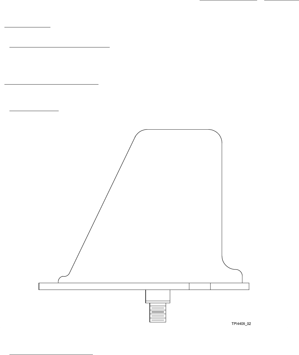
2.4.1. ANT-42 Illustration.
Refer to Figure 2-1 for an illustration of the ANT-42.
Figure 2-1. ANT-42
2.4.2. ANT-42 Mating Connector Data.
Table 2-1 shows the mating connector hardware and tooling for the ANT-42. Also refer to Figure 2-7 for the interconnect wiring
diagram.
2-3

system components 523-0809018
NOTE
The ANT-42 only requires one of the connectors in the table that follows.
Table 2-1. ANT-42 Mating Connector Hardware and Tooling.
ANT-42 HARDWARE/TOOLING
RF connector 90° TNC for ECS cable 311201: Collins Part Number (CPN) 857-1502-020 (CTS122), Vendor Ref VC-8,
RF connector straight, TNC for ECS cable 311201: CPN 857-1502-010 (CTR122), Vendor Ref VC-8
RF connector, straight, TNC for RG-142: CPN 357-9666-000
RF connector, 90°, TNC for RG-142: CPN 357-9664-000
RF grounding gasket: CPN 018-1394-110
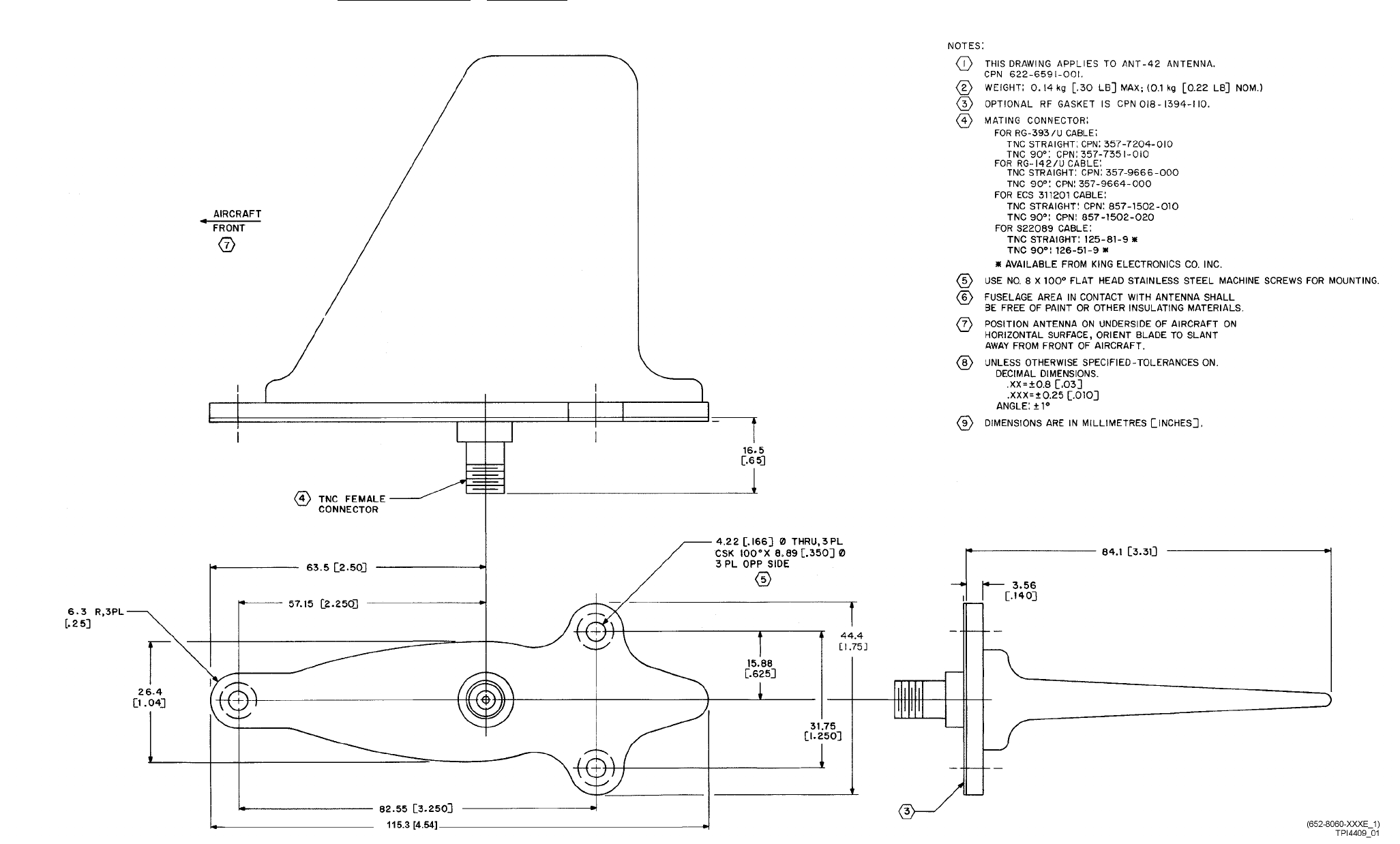
2.4.3. ANT-42 Outline and Mounting Dimensions.
Refer to Figure 2-2 for an illustration of the ANT-42 Outline and Mounting Dimensions.
2-4
system components 523-0809018
Figure 2-2. ANT-42 L-Band Antenna, Outline and Mounting Dimensions
2-5/(2-6 Blank)

system components 523-0809018
2.4.4. Installation and Removal.
Make sure that the aircraft battery master switch is turned off before installing any equipment, mounts, or inter-
connect cables. Failure to do so could irradiate the installer.
The TDR-94D ATC/Mode S transponder requires two ANT-42 antennas. One ANT-42 L-Band Antenna is mounted on top of the
fuselage and the second ANT-42 antenna is mounted on the bottom of the fuselage. All antennas should be mounted in a location
that keeps the interconnecting coaxial cables as short as practicable.
2.4.4.1. Installation. The procedure to install the ANT-42 follows (Refer to Paragraph 2.12.5.1.3 for instructions on antenna
placement relative to other antennas):
a. Verify interconnect cabling before proceeding.
b. Connect the connector to the ANT-42 antenna and position the Antenna on the fuselage.
c. Secure with three mounting screws. No. 8 Stainless steel flat head screws are recommended. Zinc, cadmium plated, or alu-
minum alloy screws are not recommended.
d. Apply any weather/aerodynamic fillet of sealant to the periphery of the antenna and shape as necessary. The height of the bead
should not exceed 2.5 mm (0.1 in).
2.4.4.2. Removal. The procedure to remove the ANT-42 follows:
a. Remove sealant around periphery of the ANT-42 antenna.
Do not allow the antenna to hang from cable. Allowing the antenna to hang from the cable could damage the
connector.
b. Remove three screws from antenna.
c. Disconnect connector from antenna.
2-7/(2-8 Blank)
system components 523-0809018
2.5. ECU-3000 34-54-00.
The sections that follow describe the external theory of operation, internal theory of operation, and general data of the External
Compensation Unit (ECU) in a Traffic Surveillance System.
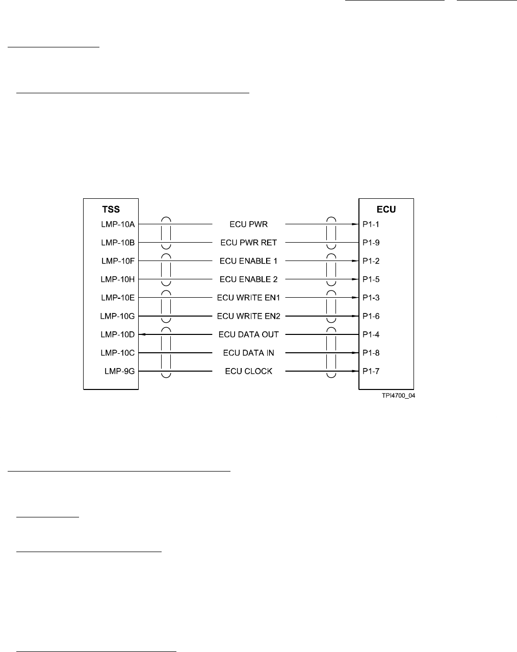
2.5.1. External Control Unit, External Theory of Operation.
The ECU is connected to the TSS through nine wires. Refer to Figure 2-3. This sheet shows a typical TSS External Compensation
Unit connection, and the external wire signals to and from the TSS.
NOTE
There should be three twisted-shielded pairs and one twisted-shielded triple when wiring the ECU to the TSS. The
wires that are bracketed together should be within the same shield.
Figure 2-3. External Compensation Unit, ECU-3000, External Simplified Schematic
2.6. EXTERNAL CONTROL UNIT , ECU-3000, DATA.
The ECU-3000 holds Rockwell Collins programmed data, aircraft-specificconfiguration data, and Mode S address. The ECU has
two halves.
2.6.1. ECU Top Half.
Pre-programmed data for the TSS LRU is in the top half.
2.6.2. ECU Bottom Half, First Partition.
Refer to Table 2-2 for a list of the parameters that need to be set and their possible values. The first partition of the bottom half has
the characteristics that follow:.
• Programmed by the installer
• Contains installation strapping, including number of GPSs, ARINC 429 bus speeds, airplane height and length, etc.
• Must be data loaded.
2.6.3. ECU Bottom Half, Second Partition.
The second partition of the bottom half is used to store the Mode S address, and has the characteristics that follow:
2-9

system components 523-0809018
• Programmed by the installer
• Contains the Mode S address
• Either data loaded, or programmed using the TSS-4100 ECU Mode S Address Programming Tool.
Table 2-2. ECU Installation Strapping Data.
Description Values Recommend (Function Using Setting)
Installation Part Number Up to 16 alpha-numeric characters
Aircraft Installation 0000 0000 = Default
0000 0001 = BRS
Recommend: 0000 0001 (BRS)
Antenna Monitoring 1 = Enable Antenna Monitoring
0 = Disable Antenna Monitoring
Recommend: 1 (Enable)
Antenna Coaxial Cable Loss Upper 00 = Not used
01 = 0 to 1 db
10 = 1 to 2 db
11 = 2 to 3 db
Antenna Coaxial Cable Loss Lower 00 = Not used
01 = 0 to 1 db
10 = 1 to 2 db
11 = 2 to 3 db
Antenna Coaxial Cable Delay 00 = 0 to 50 nsec
01 = 51 to 150 nsec
10 =151 to 250 nsec
11 = 251 to 300 nsec
Cable Delay Sign Bit 1 = Add Cable Delay to Bottom Antenna
0=AddCableDelaytoTopAntenna
Share Antennas 1 = Enable (share antennas)
0 = Disable (independent antennas)
Recommend: 0 (Disable)
Bearing Lookup Configuration 0 = Standard
1 = Enhanced
Recommend: 1 (Enhanced)
Fan Speed 0 = 0 (Fan monitor not connected)
1..255 = 500..127500 (X times 500)
(In Pulses Per Minute)
Recommend: 42 (21000 pulses per
minute) if have TSM; 0 otherwise
RA Valid Discrete Disable 1 = Disable RA Display Status Discrete
Monitor
0 = Enable RA Display Status Discrete
Monitor
Recommend: 0 (Enable) (TCAS)
Display All Traffic/Threat Traffic 1 = Display all intruders
0 = Display only TA and RA intruders
Recommend: 1 (Display all) (TCAS)
Ground Display Mode 1 = TCAS in Standby mode on ground
0 = TCAS in to TA Only mode on ground
Recommend: 0 (TA Only mode) (TCAS)
TA Display Intruder Limit Range 0 - 31 decimal Recommend: 31 (TCAS)
Default Altitude Limit A Range 0 - 127 decimal Recommend: 27 (2,700 ft) (TCAS)
2-10

system components 523-0809018
Table 2-2. ECU Installation Strapping Data. - Continued
Description Values Recommend (Function Using Setting)
Default Altitude Limit B Range 0 - 127 decimal Recommend: 99 (9,900 ft) (TCAS)
Aural Files Used 1 = Aural Files Used
0 = Aural Files Not Used
(TCAS)
Aural Advisory Discrete Delay 1 = Add delay to Aural Advisory discrete
output
0=Nodelay
(TCAS)
In Air Volume 000 = 16 dBm 40 mW
001 = 13 dBm 20 mW
010 = 10 dBm 10 mW
011=7dBm5mW
100 = 4 dBm 2.5 mW
101 = 1 dBm 1.25 mW
110 = -2 dBm 0.625 mW
111 = 19 dBm 80 mW
NOTE
This value is only applicable if
using the TSS’s 600 ohm output.
Audio power output tolerance is
+35%/-25% of power outputs show
in Watts (TCAS)
On Ground Volume 000 = Match “In Air Volume”
001 = 13 dBm 20 mW
010 = 10 dBm 10 mW
011=7dBm5mW
100 = 4 dBm 2.5 mW
101 = 1 dBm 1.25 mW
110 = -2 dBm 0.625 mW
111 = 19 dBm 80 mW
NOTE
This value is only applicable if
using the TSS’s 600 ohm output.
Audio power output tolerance is
+35%/-25% of power outputs show
in Watts (TCAS)
Maximum Climb Altitude Range 0 - 31 decimal (TCAS)
Aircraft Category (maximum takeoff
weight)
0000 = Not available
0001 = < 15,500 lbs
0010 = 15,500 to 75,000
0011 = 75,000 to 300,000
0100 = High Vortex Large
0101 = > 300,000
0110 = High Performance
0111 = Rotorcraft
1000 through 1111 = Reserved for Set
“B”
(ADS-B)
Maximum Cruising Airspeed 000 = Not available
001 = 0 to 75 knots
010 = 75 to 150 knots
011 = 150 to 300 knots
100 = 300 to 600 knots
101 = 600 to 1200 knots
110 = more than 1200 knots
111 = not used
(ADS-B)
2-11

system components 523-0809018
Table 2-2. ECU Installation Strapping Data. - Continued
Description Values Recommend (Function Using Setting)
Aircraft Length/Width 0000 = L 15m, W 11.5m
0001 = L 15m, W 23m
0010 = L 25m, W 28.5m
0011 = L 25m, W 34m
0100 = L 35m, W 33m
0101 = L 35m, W 38m
0110 = L 45m, W 39.5m
0111 = L 45m, W 45m
1000 = L 55m, W 45m
1001 = L 55m, W 52m
1010 = L 65m, W 59.5m
1011 = L 65m, W 67m
1100 = L 75m, W 72.5m
1101 = L 75m, W 80m
1110 = L 85m, W 80m
1111=L>85m,W>80m
(ADS-B)
FMS Surveillance Integrity Limit 00 = Unknown
01 = e-3
10 = e-5
11 = e-7
Recommend: 00 (Unknown) (ADS-B)
GPS Surveillance Integrity Limit 00 = Unknown
01 = e-3
10 = e-5
11 = e-7
Recommend: 10 (e-5) (ADS-B)
GPS Time Mark Source 00 = No GPS Time Mark
01 = Single GPS Time Mark Only
10 = Dual GPS Time Mark
11 = Not Used
(ADS-B)
Position Offset Applied 1 = Position Offset applied
0 = No offset applied
Recommend: 0 (No offset) (ADS-B)
Allow/Disallow Use of GPS from
Concentrator
1 = Disallow use of GPS data from IAPS
bus
0 = Allow use of GPS data from IAPS
busses
Cross-side XPDR Installed 1 = Installed 0 = Not Installed (TCAS)
Dual or Triple AHRS 1 = Triple 0 = Dual
ADLP Installed 1 = ADLP Installed
0 = ADLP Not Installed
Recommend: 0 (Not Installed) (XPDR)
Bus Speed LMP-1DC (Control A Input) 1 = High Speed
0 = Low Speed
Bus Speed LMP-7DC (Control B Input) 1 = High Speed
0 = Low Speed
Bus Speed RMP-1DC (Control C Input) 1 = High Speed
0 = Low Speed
2-12

system components 523-0809018
Table 2-2. ECU Installation Strapping Data. - Continued
Description Values Recommend (Function Using Setting)
Bus Speed LMP-8HG (IAPS #1 Input) 1 = High Speed
0 = Low Speed
Bus Speed RMP-8HG (IAPS #2 Input) 1 = High Speed
0 = Low Speed
Bus Speed RMP-8AB (XT2 (XPDR to
TSS) or ADLP Input)
1 = High Speed
0 = Low Speed
Bus Speed RMP-8DC (TX2 (TSS to
XPDR) or ADLP Output)
1 = High Speed
0 = Low Speed
Bus Speed LMP-1EF (TA/RA-1 Output) 1 = High Speed
0 = Low Speed
Bus Speed RMP-1EF (TA/RA-2 Output) 1 = High Speed
0 = Low Speed
Bus Speed LMP-7AB (TSS-1 Output) 1 = High Speed
0 = Low Speed
Bus Speed LMP-1AB (TSS-2 Output) 1 = High Speed
0 = Low Speed
Bus Speed RMP-1AB (TSS-3; Data
Load Output)
1 = High Speed
0 = Low Speed
Bus Speed LMP-7JK (Data Load Input) 1 = High Speed
0 = Low Speed
Bus Speed LMP-6HG (GPS #1 Input) 1 = High Speed
0 = Low Speed
Bus Speed RMP-2HG (GPS #2 Input) 1 = High Speed
0 = Low Speed
Bus Speed LMP-7EF (ADS-B #1 Input
Provision)
1 = High Speed
0 = Low Speed
Bus Speed LMP-7HG (ADS-B #2 Input
Provision)
1 = High Speed
0 = Low Speed
Bus Speed LMP-9EF (ADS-B #1 Output
Provision)
1 = High Speed
0 = Low Speed
Bus Speed LMP-8JK (CMU #1 Input
Provision)
1 = High Speed
0 = Low Speed
Bus Speed RMP-8JK (CMU #2 Input
Provision)
1 = High Speed
0 = Low Speed
Bus Speed RMP-9EF (CMU Output
Provision)
1 = High Speed
0 = Low Speed
2-13
system components 523-0809018
Table 2-2. ECU Installation Strapping Data. - Continued
Description Values Recommend (Function Using Setting)
Bus Speed RMP-7DC (A768 Future
Input Provision)
1 = High Speed
0 = Low Speed
Bus Speed LMP-9DC (General Purpose
#1 Provision Output)
1 = High Speed
0 = Low Speed
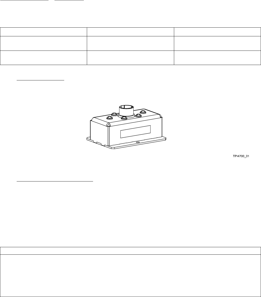
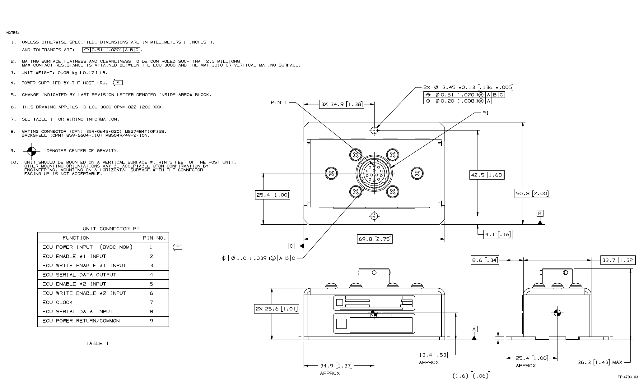
2.6.4. ECU-3000 Illustration.
Refer to Figure 2-4 for an illustration of the ECU-3000.
Figure 2-4. ECU-3000
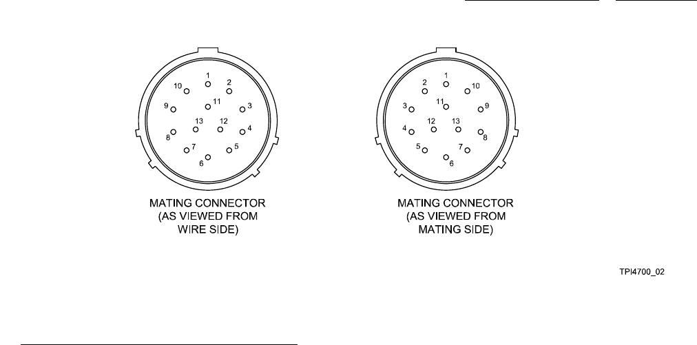
2.6.5. ECU-3000 Mating Connector Data.
NOTE
The wiring to the ECU should be done with three twisted shield pairs and one twisted shield triple.
Figure 2-5 shows a mating connector pictorial for the ECU-3000. Each connector shows pin locations to aid the troubleshooting
effort. Also refer to the interconnect wiring diagram in the appendix.
2.6.5.1. Table 2-3 shows the mating connector hardware and tooling for the ECU-3000.
Table 2-3. ECU-3000 Mating Connector Hardware and Tooling.
ECU-3000 HARDWARE/TOOLING
Mating connector: MIL MS27484T10F35S, Collins 359-0645-020
Contacts: MIL M39029/57-354, Collins 359-0608-110
Strain relief: MIL M85049/49-2-10N, Collins 859-6604-110
Insertion/extraction tool: MIL M81969/14-01, Collins 359-8032-010
Crimp tool: MIL M22520/2-01, Collins 359-8102-010
Crimp tool positioner: MIL M22520/2-06, Collins 359-8102-060
2-14
system components 523-0809018
Figure 2-6. ECU-3000 Outline and Mounting Dimensions
2-17/(2-18 Blank)

system components 523-0809018
2.6.7. Installation and Removal.
Make sure that the aircraft battery master switch is turned off before installing any equipment, mounts, or inter-
connect cables. Failure to do so can damage the equipment.
The unit should be mounted on a vertical surface. Other mounting orientations may be acceptable upon confir-
mation by engineering. Mounting on a horizontal surface with the connector facing up is not acceptable, and can
cause operational failure or damage to the ECU due to water that does not drain out.
For installations with a TSS, the maximum length of each wire between the TSS and the ECU should be one meter
to avoid potentially damaging currents.
NOTE
Refer to the ECU-3000 outline and mounting diagram Figure 2-6 for further instructions. Refer to Table 2-3 for
specific mating connector and contact information.
The installation and removal instructions for the ECU-3000 follow.
2.6.7.1. Installation. The ECU-3000 is designed to stay with the aircraft during a TSS-4100 removal. The ECU-3000 is designed
to be secured to a vertical surface of the aircraft frame. Instructions for installing the unit are as follows:
a. Remove aircraft power.
b. Secure the ECU to the mounting surface with two mounting screws.
c. Connect the mating connector cable assembly to the unit connector.
2.6.7.2. Removal. The procedure to remove the ECU-3000 follows:
a. Remove aircraft power.
b. Disconnect the mating connector cable assembly from the unit connector.
c. Remove the two mounting screws that secure the ECU to the mounting surface.
2.6.8. Internal Theory of Operation.
The ECU-3000 is used to store aircraft specificconfiguration data. The ECU has two halves in which it stores data. The top half
is programmed by Rockwell Collins to enable basic functionality of the TSS. The bottom half is programmed by the aircraft manu-
facturer. There are two partitions of this bottom half. The first partition contains all of the aircraft specific transponder, TCAS, and
ADS-B strapping information. The second partition contains the aircraft Mode S address.
2-19/(2-20 Blank)

system components 523-0809018
2.7. TDR-94D 34-54-00.
The sections that follow describe the external theory of operation, internal theory of operation, and general data of the Mode S
transponder in a traffic surveillance system.
2.7.1. Mode S Transponder, External Theory of Operation.
NOTE
The term CONTROLLER refers to any transponder control unit, such as an Radio Tuning Unit (RTU), a Transpon-
der Control (CTL), or a Control Display Unit (CDU). Buses and discretes are followed in parentheses by the spe-
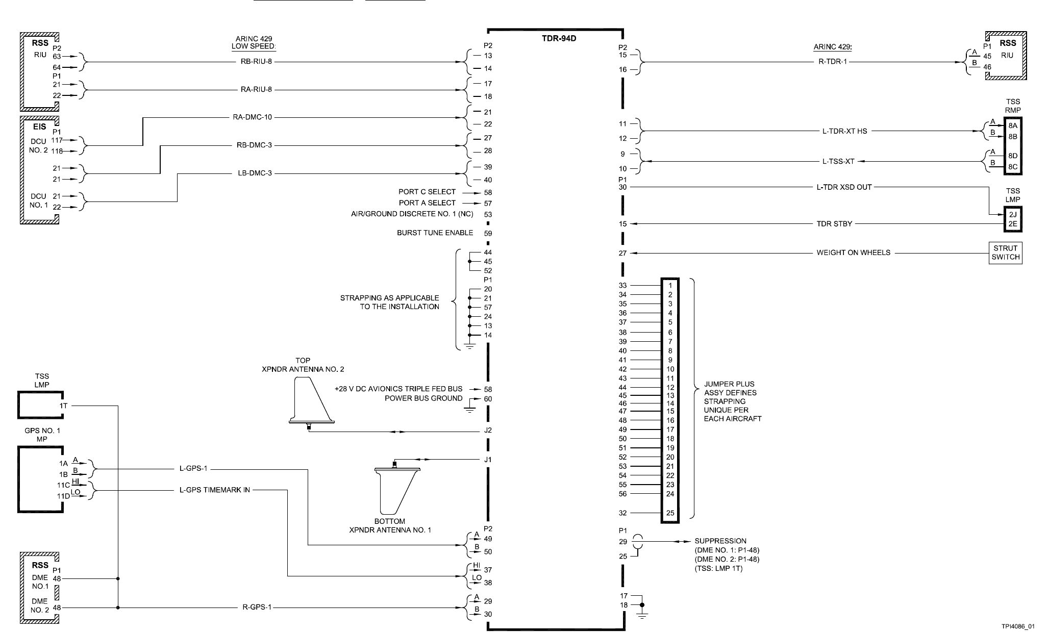
cific bus name shown in the example illustration, Figure 2-7.
Refer to Figure 2-7. This sheet shows a typical transponder system, and the external signals to and from the Transponder (TDR).
Operating power is derived from the +28 V dc avionics triple-fed bus supply.
2.7.1.1. The TDR is controlled by an ARINC standard transponder controller such as an RTU or a CDU. A controller provides the
transponder state (STANDBY, ALTITUDE REPORTING OFF, ALTITUDE REPORTING ON), the flight ID, the squawk code, the
selected altitude, and TCAS control data.
2.7.1.2. Either two or three ARINC 429 low-speed control busses may be routed to the TDR containing control and altitude data.
The on-side data comes to Control Port B. The cross side data comes to Control Port A. An optional back up third controller comes
to Control Port C. The microprocessor reads the discrete (RTU PORT A/B SELECT, P2-57) and selects the active port. Normally,
port B is selected and the TDR is tuned by the on-side controller (RTU). When the reversion switch (RTU1 INHB) is set to inhibit, a
ground is applied to pin P2-57, which selects port A of the right side controller (RTU) tune data. When the reversion switch (RTU2
INHB) is also set to inhibit, a ground (BURST TUNE ENABLE) is applied to pin P2-59, which selects port C (IAPS) burst tune
data.
2.7.1.3. The TCAS/transponder cross talk busses (TSS-TX and TDR-XT busses) are used for coordination between the TCAS
function of the TSS and the TDR.
2.7.1.4. The Mode S address is set by rear connector strapping (P1-33 through P1-56) and is unique for each aircraft.
2.7.1.5. The main transponder output bus (TDR-1) outputs maintenance data and echoes selected control data.
2.7.1.6. The TDR-94D operates with two antennas to provide traffic air-to-air capability. The 1030 Hz interrogation input is
received on either or both L-band antennas, low-pass filtered, and applied through diversity and transmit/receive switches to the
front-end receiver. The diversity switch is not used in receive mode. The transmit/receive switch connects the antennas to the re-
ceiver (not the transmitter) in receive mode.
2.7.1.7. The TDR responds to Air Traffic Control Radar Beacon System (ATCRBS) and Mode S All-Call interrogations.
2.7.1.8. The TDR also responds to selective Mode S interrogations. These interrogations use the transponder Mode S address.
This mode allows the air traffic controller to identify each aircraft by tail number. It is also used by the traffic surveillance system
for air-to-air communication with a cooperating aircraft.
2.7.1.9. A suppression pulse (P1-29) is generated while the TDR is transmitting a response to an interrogation. This pulse is
intended to inhibit the receivers in other L-band radios, such as the TSS and the DME. These other radios also generate a suppression
pulse while they are transmitting. While this is active the TDR will inhibit its replies.
2-21/(2-22 Blank)
system components 523-0809018
Figure 2-7. Mode S Transponder, TDR-94D, External Theory of Operation
2-23/(2-24 Blank)
system components 523-0809018
2.8. MODE S TRANSPONDER, TDR-94D, DATA.
The TDR-94D is a Mode-A, Mode-C, and Mode-S diversity (two antenna) transponder.
2.8.1. TDR-94D ATC/Mode S Transponder Mounting Considerations.
The TDR-94D transponder is mounted on the MMT-150 Modular Mounting Tray, CPN 622-9672-XXX. Piggyback mounting brack-
ets are available to mount an MMT-150 Modular Mounting Tray over another MMT-150 Modular Mounting Tray. Refer to the Pro
Line II Installation Manual (CPN 523-0772719) for additional information.
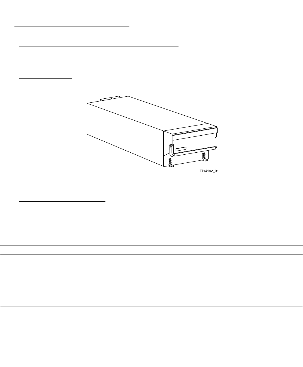
2.8.2. TDR-94D Illustration.
Refer to Figure 2-8 for an illustration of the TDR-94D.
Figure 2-8. TDR-94D
2.8.3. TDR-94D Mating Connector Data.
Figure 2-9 shows a mating connector pictorial for the TDR-94D. Each connector shows pin locations to aid the troubleshooting
effort. Refer to Figure 2-11 for internal signals for the TDR-94D. Also refer to the interconnect wiring diagram in the appendix.
Table 2-4 shows the mating connector hardware and tooling for the TDR-94D.
Table 2-4. TDR-94D Mating Connector Hardware and Tooling.
TDR-94D HARDWARE/TOOLING
Mating connector kit: CPN 628-8661-001 (qty 2)
Connector: 60-pin Thinline II, CPN 634-1112-001
Contacts: CPN 372-2514-110 (insulation up to 1.27 mm (0.050 in) diameter)
Contacts: CPN 372-2514-180 (insulation from 1.27 mm (0.050 in) to 2.03 mm (0.080 in) diameter)
TNC connector: Automatic 301-T2100N, CPN 357-7351-010 (qty 2)
Tooling *
*Thinline II Connector Tooling:
Insertion tool: Daniels DAK-188, CPN 359-0697-050
Extraction tool: Daniels DRK-188, CPN 359-0697-060
Crimp tool: Daniels GMT-221, CPN 359-0697-010
Coax extraction tool: Cannon CET-C6B, CPN 370-8040-030
Coax crimp tool: MIL M22520/5-01, CPN 359-8103-010
Crimp tool positioner: Daniels Y142, CPN 359-8103-050
2-25

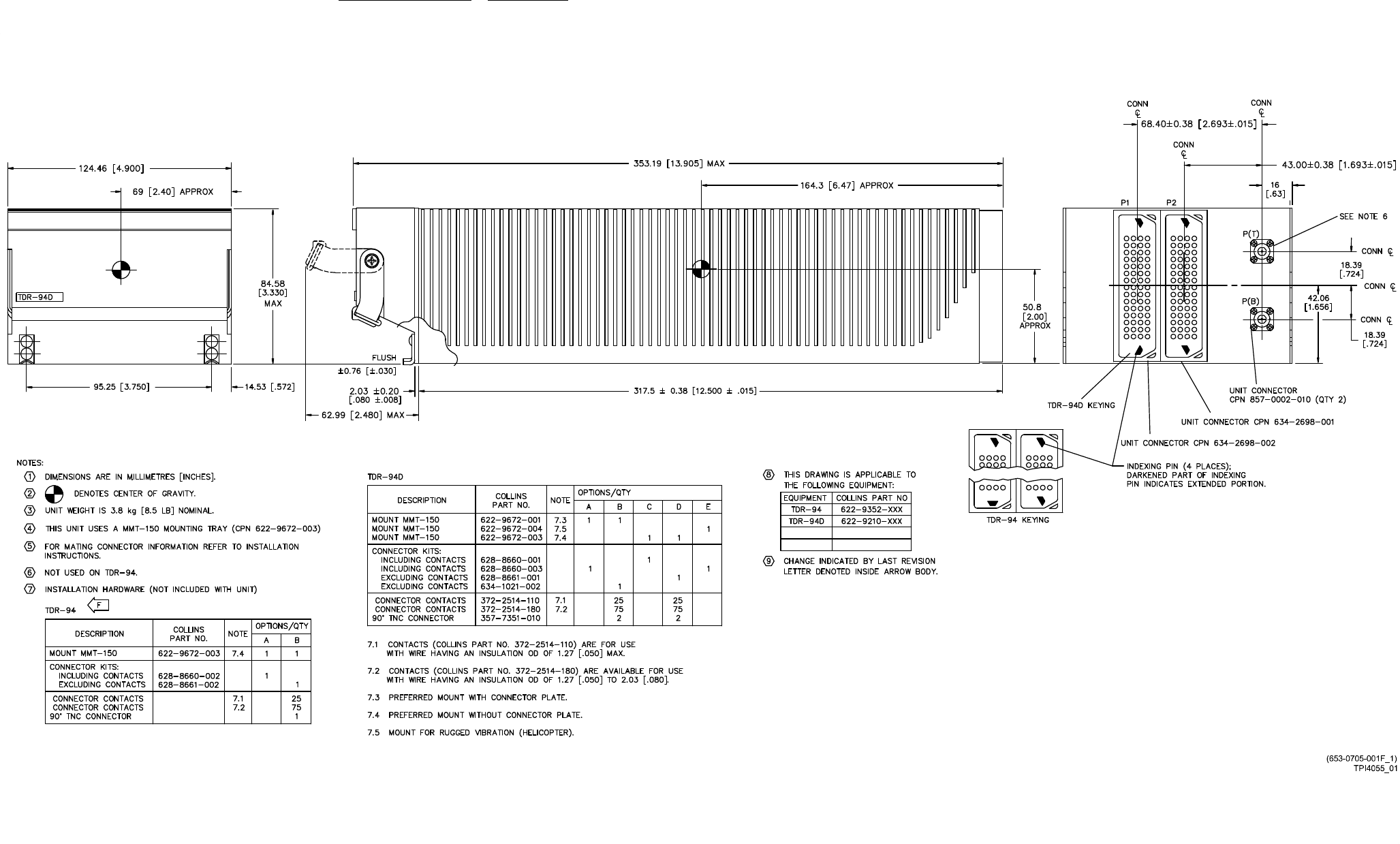
system components 523-0809018
Figure 2-10. TDR-94D Outline and Mounting Dimensions
2-27/(2-28 Blank)

system components 523-0809018
2.8.5. Installation and Removal.
Make sure that the aircraft battery master switch is turned off before installing any equipment, mounts, or inter-
connect cables.
The installation and removal instructions for the TDR-94D follow.
2.8.5.1. Installation. The procedure to install the TDR-94D follows:
a. Remove electrical power from the aircraft.
b. Install the MMT-150 Modular Mounting Tray and connector kit according to the procedures printed in the Pro Line II Installa-
tion Manual (CPN 523-0772719).
c. Install and orient the mating connector keyway pins, (part of the mating connector kits). If installing systems on multiple
aircraft, similar orientation of the keyways is advisable for quick maintenance removal and replacement.
d. Verify all interconnect wiring before proceeding. Verify input power is applied to appropriate pins only.
e. Remove aircraft power and slide TDR-94D ATC/Mode S Transponder into mount until mating connector is fully engaged.
f. Position knurled knobs on front of mount to engage unit-mounting projections and tighten knurled knobs.
g. Push on the front panel to make sure that the unit is fully seated in the mount. Retighten the knurled knobs until the unit is
secure in mount.
h. Make sure a good electrical bond exists between the unit and mount.
i. Install safety wire.
2.8.5.2. Removal. The procedure to remove the TDR-94D follows:
a. Remove electrical power from the aircraft.
b. Remove the safety wire.
c. Loosen the knurled knobs that secure the unit to the mount.
d. Pull TDR-94D ATC/Mode S Transponder from mount.
2.8.6. Internal Theory of Operation.
Refer to Figure 2-11. When active, the TDR responds to valid ATCRBS radar interrogations with a coded identificationinMode-A
or reporting altitude in Mode-C reply. The response code is selected on the controller.
2.8.6.1. The TDR consists of a main microprocessor, serial and discrete I/O interfaces, a 1030 MHz receiver, an interrogation
processor, and a 1090 MHz transmitter. Operating power is derived from the +28 V dc avionics triple-fed bus supply. This input is
filtered and applied through an internal breaker to the low-voltage power supply. This supply generates internally required low-level
voltages, and feeds the high-voltage power supply. A voltage monitor reports power supply integrity to the microprocessor.
2.8.6.2. Refer to Figure 2-11. The main microprocessor uses a 16-bit bidirectional data bus to control unit operation. An address
latch and a data transceiver provide the interface between the processor and internal circuits. This processor controls all I/O data
transfer, monitors key internal power levels, programs the frequency synthesizer, generates high-voltage supply disable logic, and
shares data with the dedicated video processor through a dual-port Random Access Memory (RAM). The processor also directly
monitors the temperature of the transmit modulator. If temperature becomes excessive, data is latched that toggles a discrete to
inhibit the high-voltage power supply.
2.8.6.3. The I/O interface circuits consist of three input UARTs, two discrete input buffers, and two output UARTs. The main
microprocessor accesses each circuit using the bidirectional data bus (DB0-DB15).
2.8.6.4. ARINC 429 low-speed data buses are received and applied to the RTU multiplexer. The microprocessor reads the PORT
A/B select discrete and selects the active port. The RTU multiplexer supplies control data from the selected port, A or B, through
an input UART to the microprocessor.
2.8.6.5. The second input UART is reserved for two Air Data Computer (ADC) air data input buses.
2-29

system components 523-0809018
2.8.6.6. The data bus input through an ARINC 429 high-speed receiver to the third input UART is read from the UART by the
microprocessor.
2.8.6.7. The processor reads the discrete inputs through two buffer circuits. The first buffer provides the input port A/B select
logic, strut switch logic, source identification logic, maximum airspeed logic, altitude input logic, and TCAS installed logic.
2.8.6.8. Parallel data is output from the microprocessor to the output UARTs. Both UARTs are enabled by the processor to decode
and transmit serial data.
2.8.6.9. The TDR is interrogated by the 3-pulse Side-Lobe-Suppression (SLS) method. The TDR-94D operates with one antenna
to provide TCAS air-to-air capability. The 1030-MHz interrogation input is received on the L-band antenna, low-pass filtered,
and applied through the transmit/receive switch to the front end receiver. The transmit/receive switch connects the antennas to the
receiver, but not the transmitter, in receive mode.
2.8.6.10. The front end receiver is a dual 1030-MHz bandpass filter that rejects images and spurious responses. The two filtered
rf inputs are then independently mixed with a 1090-MHz injection frequency from the synthesizer. This local oscillator frequency is
programmed by the microprocessor using latched data, clock, and enable logic. The two resultant 60-MHz if signals are amplified
and applied to the Differential Phase Shift Keying (DPSK) detector and the video processor.
2.8.6.11. The DPSK detector is a part of the receiver circuit that senses phase reversals present in mode-S interrogations. The
DPSK detector outputs are applied to the Pulse Amplitude Modulation (PAM) decoder. The video processor monitors the received
signal strengths and generates video signals to the PAM decoder.
2.8.6.12. The PAM decoder and a dedicated video microprocessor function together as an interrogation processor. This circuit
processes the video inputs to determine if the received interrogation is a valid ATCRBS or Mode-S interrogation. If a response
is required, the processor determines if the top or the bottom antenna should be used for the reply. The processor then enables the
transmit mode and generates the proper response. The TCAS generated collision avoidance transmit data is input to the interrogation
processor through the dual port RAM.
2.8.6.13. When transmit mode is enabled by the interrogation processor, INT SUPRN logic activates the suppression amplifier and
XMT ENBL logic activates the transmit enable driver. During transmit mode, the suppression amplifier momentarily inhibits other
L-band units, described in a later paragraph. During transmit mode, the enable driver closes the transmit/receive switch. This isolates
the receiver and connects the transmitter to the selected antenna. The interrogation processor generates the ATCRBS or Mode-S
reply output and top/bottom antenna select logic. This response is applied through a multiplexer to the rf transmit modulator.
2.8.6.14. The 1090-MHz transmitter circuit consists of an rf modulator and a power amplifier. The rf modulator receives operating
power from the high-voltage power supply. This power supply provides the voltage levels required for L-band transmission. A
current monitor disables both the rf modulator and the High-Voltage (HV) supply if the current draw or power output becomes
excessive. An HV power monitor provides a high-power monitor output through a buffer to the main microprocessor.
2.8.6.15. The reply output from the interrogation processor controls the modulator bias applied to the power amplifier. The power
amplifier is driven by a 1090-MHz CW signal generated by the synthesizer. The ON/OFF BIAS from the modulator causes the
power amplifier to generate a corresponding pulse train output, at the 1090-MHz drive frequency. This rf reply output is a series of
pulses, the number and spacing of which is determined by the ATC code plus a trailing IDENT pulse, if selected, and the operating
mode. The pulse transmission is applied through the closed transmit/receive switch and radiated out the antenna. The transmit signal
is sampled by a forward power monitor, which provides a low-power monitor output through a buffer to the processor.
2.8.6.16. A suppression amplifier generates a blanking pulse output when the interrogation processor selects transmit mode.
2-30
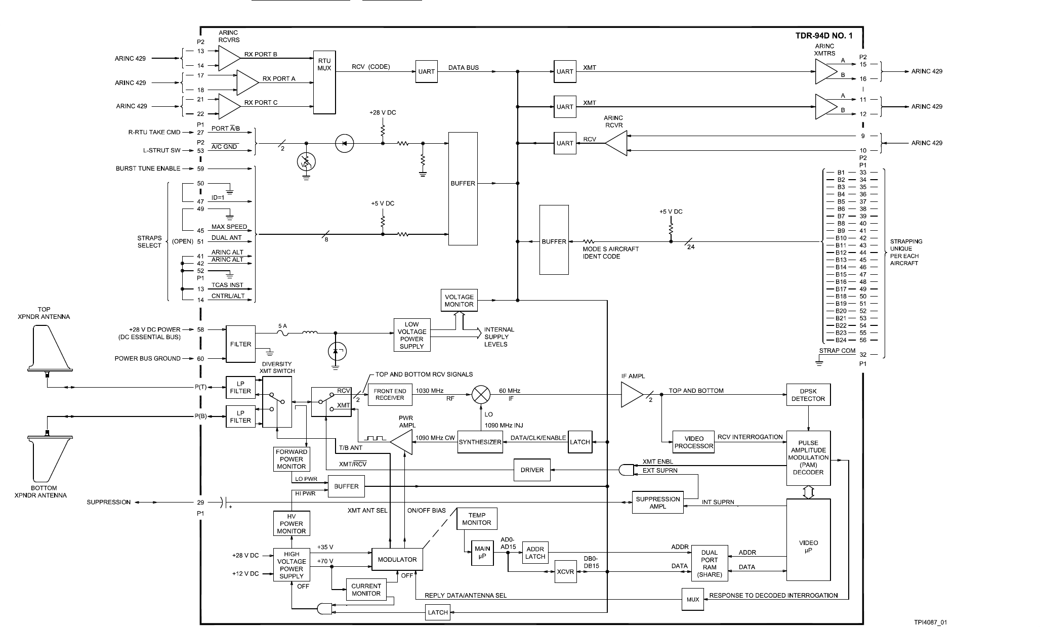
system components 523-0809018
Figure 2-11. Mode S Transponder, TDR-94D, Internal Theory of Operation
2-31/(2-32 Blank)
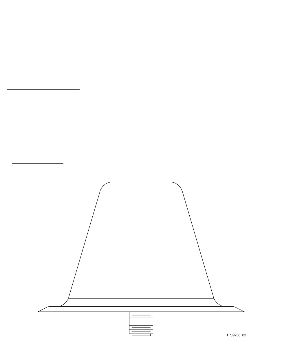
system components 523-0809018
2.9. TRE-930 34-54-00.
The sections that follow describe the external theory of operation, internal theory of operation, and general data of the TRE L-Band
Omnidirectional Antenna in the traffic surveillance system.
2.9.1. TRE-930 L-Band Directional Antenna, External Theory of Operation.
Refer to the TSS External Simplified Schematic Figure 2-19. This sheet shows the external wire signals to and from the TRE-930
and the TSS-4100. The TRE-930 antenna is a single, non-repairable unit. When used with the TSS-4100, the TRE-930 antenna
mounts only on the bottom of the aircraft. There are no operator controls or adjustments on this antenna.
2.10. ANTENNA, TRE-930, DATA.
NOTE
If the TRE-930 or any other omni-directional antenna is used, the option for antenna monitoring in the aircraft
configuration portion of the ECU must be enabled. The TSS uses antenna monitoring to determine that there is
only a single connection on the bottom of the aircraft. If antenna monitoring is off, the TSS will assume that
there is a directional antenna on the bottom of the aircraft. If antenna monitoring is off, any TSS antenna port not
connected to an antenna may cause a failure of the TSS transmitter or receiver.
The TRE is an L-band omnidirectional antenna. The TRE radiates and receives L-band signals in an omnidirectional pattern.
2.10.1. TRE-930 Illustration.
Refer to Figure 2-12 for an illustration of the TRE-930.
Figure 2-12. TRE-930
2-33

system components 523-0809018
2.10.2. TRE-930 Mating Connector Data.
Table 2-5 shows the mating connector hardware and tooling for the TRE-930. Also refer to the interconnect wiring diagram in the
appendix.
Table 2-5. TRE-930 Mating Connector Hardware and Tooling.
TRE-930 HARDWARE/TOOLING
RF connector 90° TNC for ECS cable 311201: CPN 857-1502-020 (CTS122), Vendor Ref VC-8,
RF connector straight, TNC for ECS cable 311201: CPN 857-1502-010 (CTR122), Vendor Ref VC-8
RF connector, straight, TNC for RG-142: CPN 357-9666-000
RF connector, 90°, TNC for RG-142: CPN 357-9664-000
RF grounding gasket: CPN 018-1394-110
2.10.3. TRE-930 Outline and Mounting Dimensions.
Refer to Figure 2-13 for an illustration of the TRE-930 Outline and Mounting Dimensions.
2-34
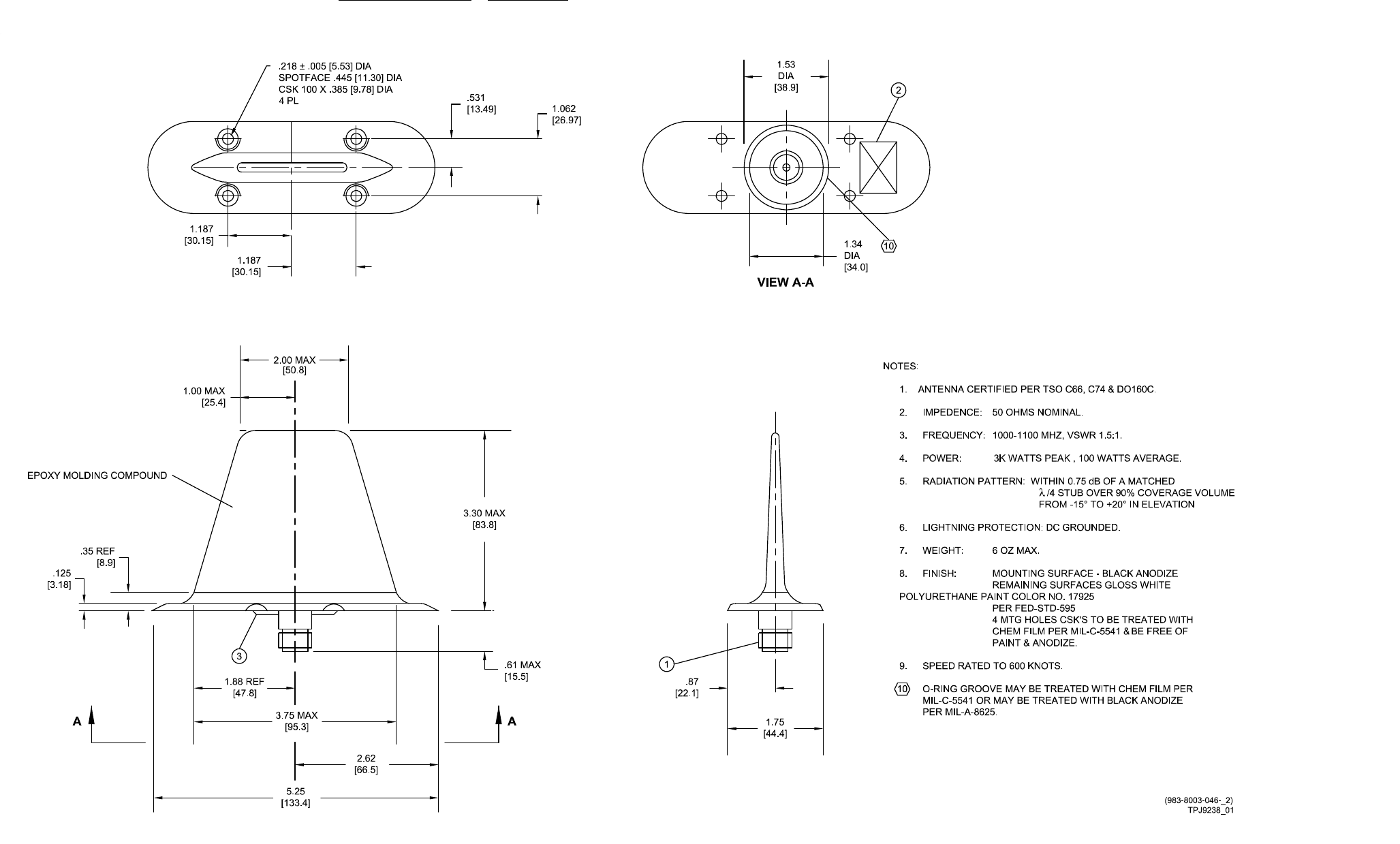
system components 523-0809018
Figure 2-13. TRE-930 L-Band Antenna, Outline and Mounting Dimensions
2-35/(2-36 Blank)

system components 523-0809018
2.10.4. Omni-Directional Requirements.
If a different antenna is used instead of a TRE-930, there are requirements to be compatible with the TSS-4100. There are also
requirements to facilitate certification with a TCAS/transponder system.
2.10.4.1. The requirements of an antenna to replace the TRE-930 for use with the TSS-4100 follow:
• It must have a DC impedance of 50 .
• It must have continuous power at a minimum of 50 W.
• It must have peak power at a minimum of 4 kW.
• Itmustbecertified to work at a minimum of the maximum altitude of the aircraft.
2.10.4.2. The recommended requirements to facilitate the certification of the TCAS, transponder, and related antenna system on
an aircraft are below:
• It is recommended that the system be certified as operational, at a minimum, between -55 and 80 ºC.
• It is recommended that the system have a Voltage-Standing Wave Ratio (VSWR) of 1.5 to 1 or less, for 1000 to 1100 MHz.
• It is recommended that the system be compliant with TSO-C119. Specifically, it is recommended that the antenna comply with
the requirement in Section 2.2.4.7.2.1 of DO-185A. This requires that the gain of an omnidirectional wave pattern not be less
than the gain of a matched quarter-wave stub, minus one dB, over 90% of a coverage volume from 0 to 360 degrees in azimuth,
and -15 to +20 degrees in elevation.
2.10.5. Installation and Removal.
Make sure that the aircraft battery master switch is turned off before installing any equipment, mounts, or inter-
connect cables.
The installation and removal instructions for the TRE-930 follow.
2.10.5.1. Installation. The procedure to install the TRE-930 follows:
a. Make sure that the cabling to the TSS-4100 is correct before proceeding.
b. Connect the connector to the TRE-930 antenna and position the antenna on the fuselage.
c. Secure with four mounting screws.
d. Apply any weather or aerodynamic strip of sealant to the periphery of the antenna and shape as necessary.
2.10.5.2. Removal. The procedure to remove the TRE-930 follows:
a. Remove sealant around periphery of the TRE-930 antenna.
b. Remove the four screws from the antenna and do not allow the antenna to hang from the cable.
c. Disconnect the connector from the antenna.
2-37/(2-38 Blank)
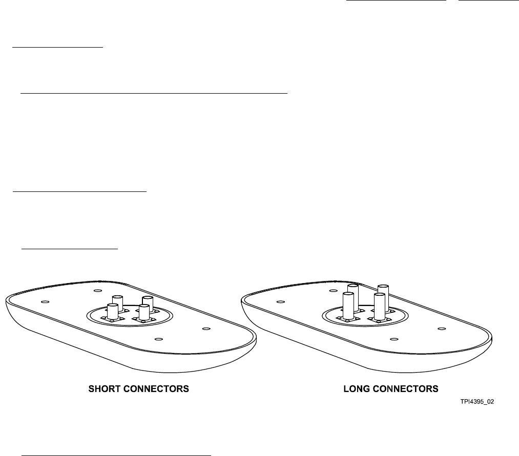
system components 523-0809018
2.11. TSA-4100 34-54-00.
The sections that follow describe the external theory and general data of the directional Traffic Surveillance Antenna (TSA) in the
Traffic Surveillance System.
2.11.1. Traffic Surveillance Antenna, External Theory of Operation.
Refer to Figure 2-18 for a simplified block diagram that includes this antenna. The TSA-4100 Antenna acts both as an omni and a
directional antenna at 1030 MHz & 1090 MHz at +/- 3 MHz for the Traffic Surveillance System. It has four passive antenna elements
for directionality and is mounted on the outside of the aircraft fuselage. The upper antenna must be the TSA-4100 directional antenna.
The lower antenna can be another TSA-4100 directional antenna or it can be an omnidirectional antenna. The return loss for each
connector is less than or equal to -12.5 dB. Meeting the MOPS requirements for TSO-C112 and TSO-C119b, the antenna is vertically
polarized. The TSA-4100 meets all lightning protection requirements for Zone 1A on an aluminum ground plane.
2.12. ANTENNA, TSA-4100, DATA.
The TSA is Mode S directional antenna. The number 1 TSA is mounted on the top of the aircraft. The optional number 2 TSA
is mounted on the bottom of the aircraft. For the TCAS function of the TSS, the TSA is directional, which allows the system to
compute bearing to a target aircraft. For the transponder function of the TSS, the TSA acts as an omnidirectional antenna.
2.12.1. TSA-4100 Illustration.
Refer to Figure 2-14 for an illustration of the TSA-4100.
Figure 2-14. TSA-4100, Short and Long Connectors
2.12.2. TSA-4100 Outline and Mounting Diagram.
NOTE
There are two versions of connectors on the TSA. One version of TSA has longer connectors, the other version
has shorter connectors. Refer to Figure 2-15 for connector lengths.
Refer to Figure 2-15 for outline and mounting diagrams of the TSA-4100 with long connectors. Refer to Figure 2-16 for outline and
mounting diagrams of the TSA-4100 with short connectors.
2-39/(2-40 Blank)
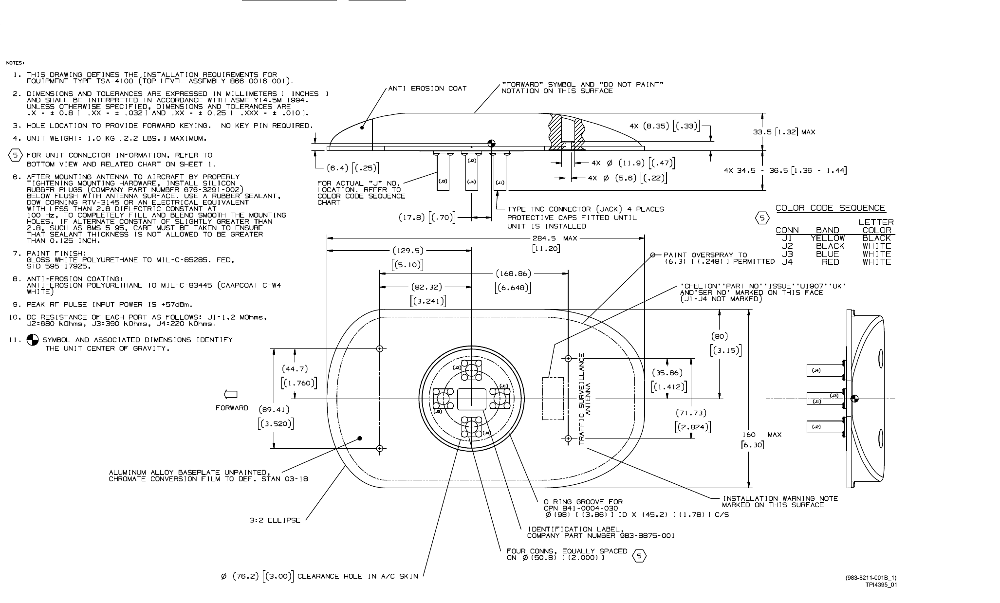
system components 523-0809018
Figure 2-15. TSA-4100 Outline and Mounting Diagram, Long Connector Version (Sheet 1 of 2)
2-41/(2-42 Blank)
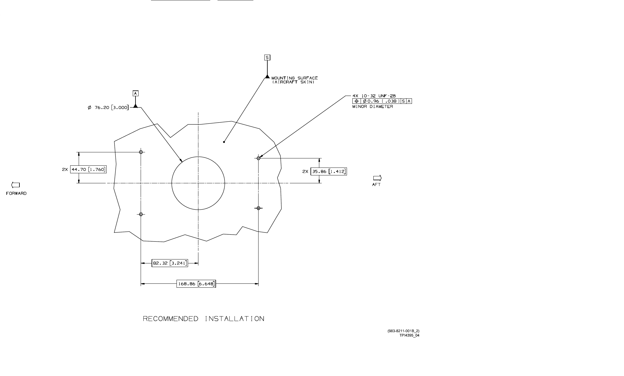
system components 523-0809018
Figure 2-15. TSA-4100 Outline and Mounting Diagram, Long Connector Version (Sheet 2 of 2)
2-43/(2-44 Blank)
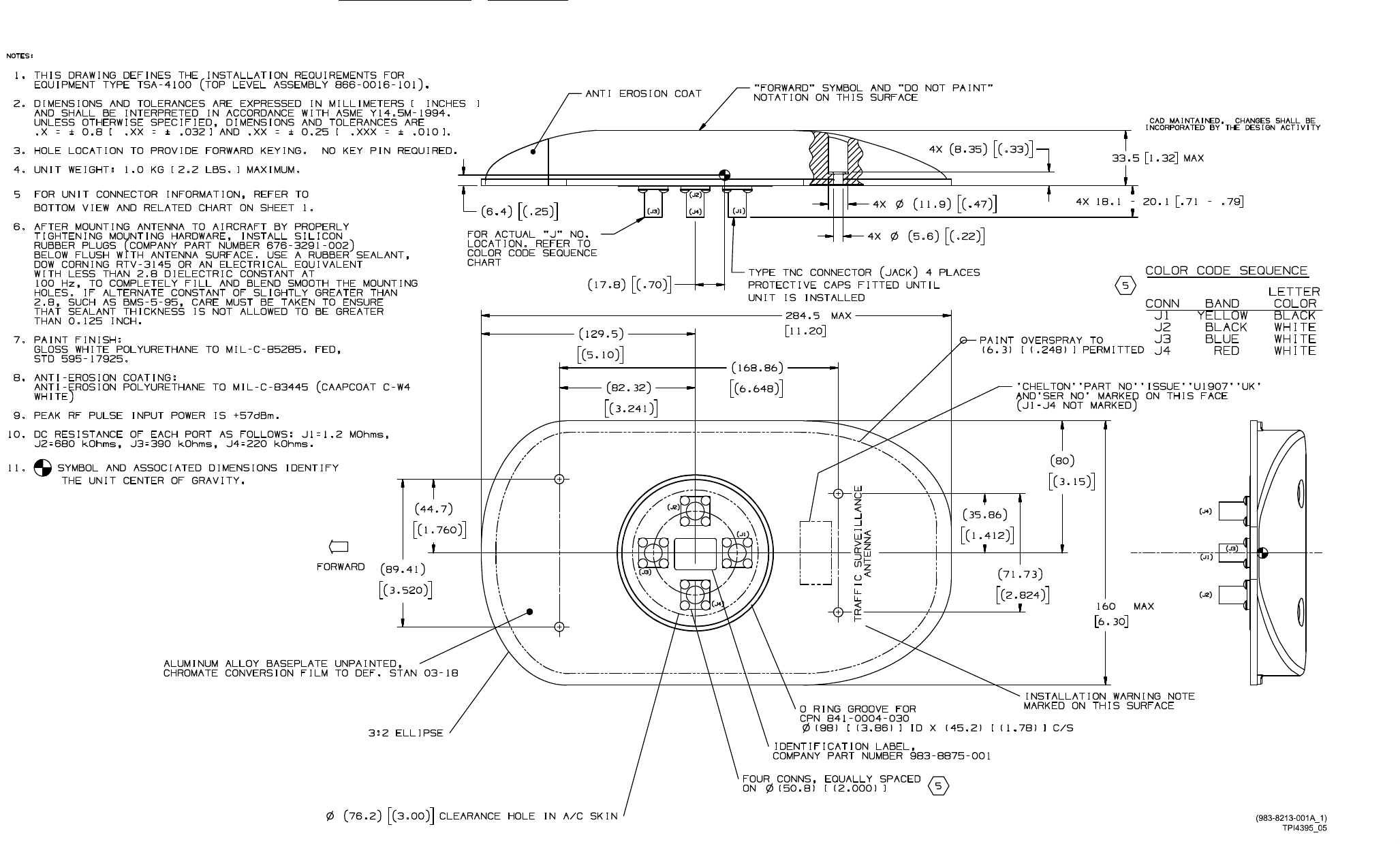
system components 523-0809018
Figure 2-16. TSA-4100 Outline and Mounting Diagram, Short Connector Version (Sheet 1 of 2)
2-45/(2-46 Blank)
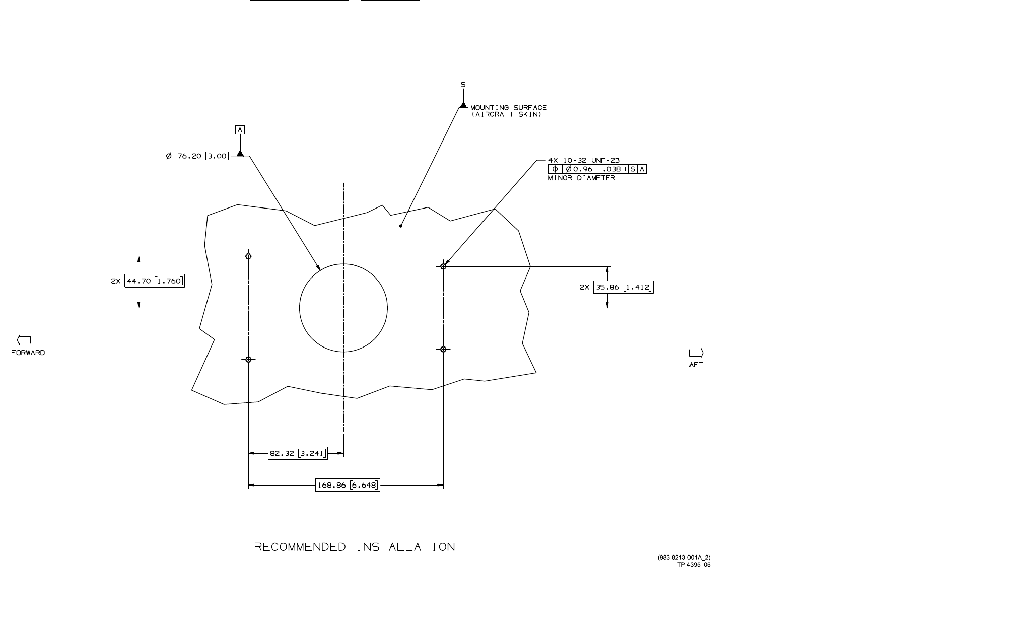
system components 523-0809018
Figure 2-16. TSA-4100 Outline and Mounting Diagram, Short Connector Version (Sheet 2 of 2)
2-47/(2-48 Blank)

system components 523-0809018
2.12.3. TSA-4100 Mating Connector Data.
Table 2-6 shows the mating connector hardware and tooling for the TSA-4100. Also refer to the interconnect wiring diagram in
Figure E-1.
Table 2-6. TSA-4100 Mating Connector Hardware and Tooling.
TSA-4100 HARDWARE/TOOLING
RF connector, TNC for RG-142, qty 4 required: CPN 357-9664-000, Mil M39012/30/0101
RF connector, straight, low loss for ECS cable: CPN 857-1502-010
RF connector 90 degrees low-loss for ECS cable: CPN 857-1502-020
Silicon rubber plug (qty 4): CPN 676-3291-002
O-ring: CPN 841-0004-030
2.12.4. Cabling Considerations.
The recommended cable for use between the TSS-4100 and the TSA-4100 is ECS 311201. Information for RG-142/U has also been
provided in the following table, but no testing has been done with the TSS using this cable. The maximum allowable loss between
the TSS and its antennas is 3.0 dB. Refer to the values below. The maximum length of the cables is calculated by dividing 3.0 dB
by the Loss Factor.
Cable Type Collins P/N Delay Loss Factor Max Length
ECS 311201 858-5804-010 1.26 ns/ft 0.0589 dB/ft 15.5 m (51 ft)
RG-142/U Not Available 4.6 ns/ft 0.13 dB/ft 7.0 m (23 ft )
2.12.4.1. The ECU contains settings based on the type and length of cable used (refer to Table 2-2). The antenna coaxial-cable
loss is calculated by multiplying the loss factor of the cable used by the length of the cable. The coaxial cable delay is calculated by
subtracting the amount of delay from the antenna that is closer to the TSS from the amount of delay from the antenna that is further
away from the TSS. The cable delay sign bit is simply a way to determine which antenna is further away from the TSS. Adding the
delay to the bottom antenna means that the bottom antenna is closer to the TSS.
2.12.4.2. The TSA-4100 directional antenna requires four antenna cables. Unlike other TCAS antennas, the TSA-4100/TSS-4100
combination does not require the four cables to be in phase. The requirements for the four cables are:
• They are of the same type.
• They are within .3 m (12 in) of length of each other (so cable delay difference between the cables is minimized).
• They are within 0.5 dB of loss of each other (including loss due to the connectors. This is so the Coaxial Cable Loss is the same
for all of the cables to the same antenna).
2.12.5. Installation and Removal.
Make sure that the aircraft battery master switch is turned off before installing any equipment, mounts, or inter-
connect cables.
One TSA-4100 Traffic Surveillance Antenna is mounted on top of the fuselage and the second antenna, either another TSA-4100 or
an omnidirectional antenna, is mounted on the bottom of the fuselage. All antennas should be mounted in a location that keeps the
interconnecting coaxial cables as short as practicable.
2.12.5.1. Antenna Placement. One TSA-4100 is mounted on top of the aircraft fuselage. Another TSA-4100 or an omnidirec-
tional antenna is mounted on the bottom.
2-49

system components 523-0809018
2.12.5.1.1. Place the antennas, especially the top antenna, as forward as possible on the aircraft fuselage. Make sure there are as
few obstructions as possible between the antenna and the front of the aircraft.
2.12.5.1.2. Make sure that the lateral deviation between the top and bottom antenna is less than 25 feet. This is to make sure that
both antennas receive and reply to an interrogation at about the same time.
2.12.5.1.3. Separate the antennas as much as possible from other antennas. The minimum distances from a TSS or TDR antenna,
to another type of antenna, are specified below:
• To an ADF antenna, 2 feet
• To a VHF antenna, 5 feet
• ToanL-bandantenna,30inches(approximately20dBisolation).
NOTE
Other L-band antennas include the DME, TDR, and TSS antennas.
2.12.5.1.4. Make sure that the tilt angle both in the longitudinal and in the latitudinal directions are as close to parallel to the
horizon as possible. Refer to Figure 2-17 for limitations on mounting the antenna.
2-50
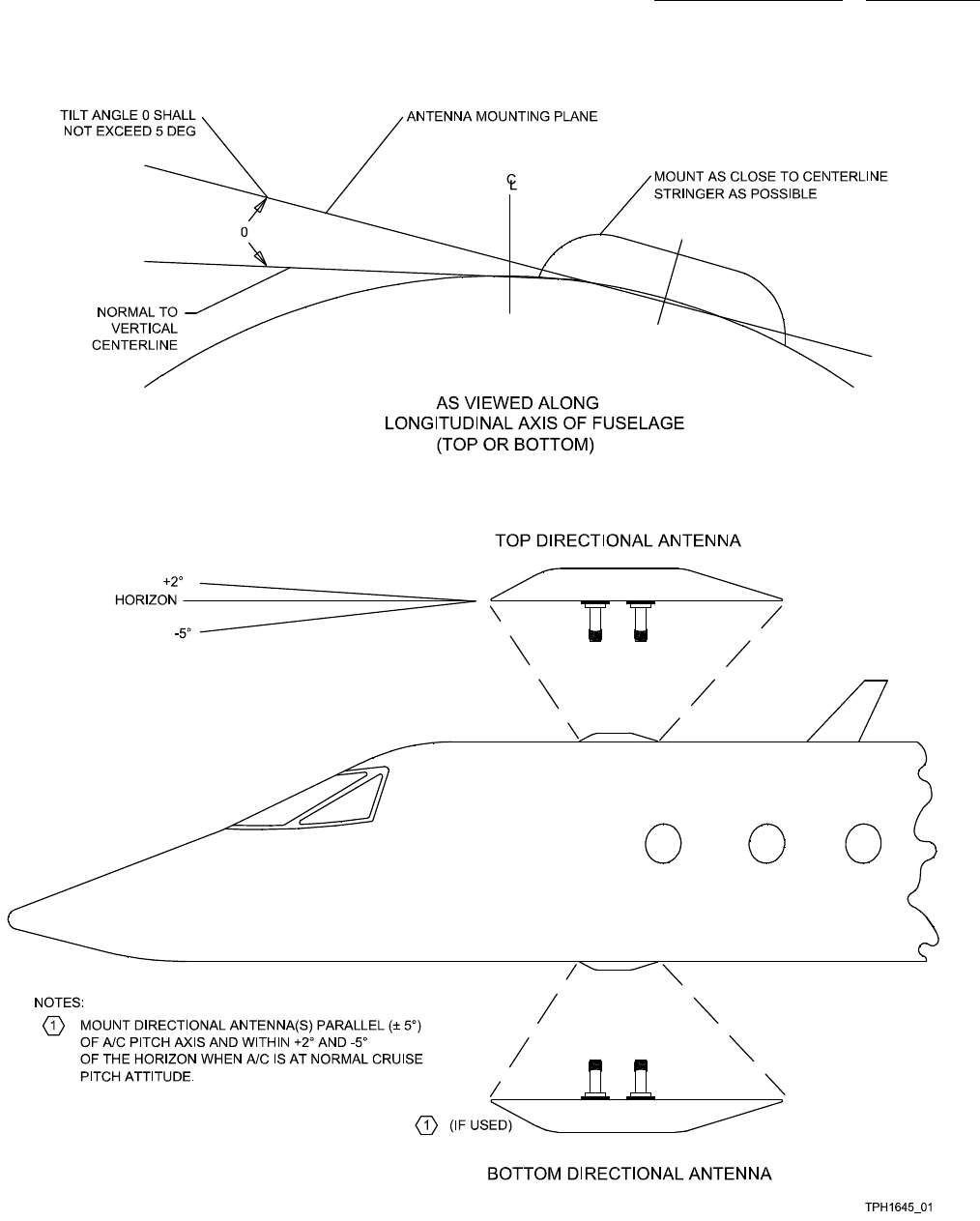
system components 523-0809018
Figure 2-17. TCAS Directional Antenna, Mounting Diagram
2-51

system components 523-0809018
2.12.5.2. Installation. To install a directional antenna, follow the steps below:
a. Make sure all interconnect cabling is correct before continuing.
b. Inspect the aircraft skin surface at the mounting location for dirt and corrosion. Clean as necessary.
c. Install an O-ring, CPN 841-0004-030, in the groove on the bottom of the antenna.
d. Connect the appropriate cable to the color-coded J1, J2, J3, and J4 of the antenna, then position the TSA-4100 Antenna.
• J1–Yellow
• J2–Black
•J3–Blue
•J4–Red.
e. Use four mounting screws to secure the antenna. Stainless-steel socket head-cap screws are recommended. Zinc, cadmium-
plated, or aluminum-alloy screws are not recommended.
f. Tighten the screws to almost contact with the bearing surface, and then torque to 25 ±5 lb in.
g. Apply any weather/aerodynamic fillet of sealant to the periphery of the antenna, and shape it as necessary. The height of the
bead should not exceed 2.5 mm (0.1 in).
h. Install the four foam-rubber plugs, CPN 676-3291-002, in the antenna mounting holes. Push them down below the antenna
surface. Cover the plugs with a layer of Dow Corning gray RTV-3145 (CPN 005-1531-010, or three 3 oz collapsible tubes, or
CPN 005-2531-030 for one 11 oz cartridge), or equivalent sealant. Feather sealant over mounting holes and remove any excess
sealant.
2.12.5.3. Removal. To remove a directional antenna, follow the steps below:
a. Remove the sealant from mounting holes and around periphery of the TSA-4100 Antenna.
b. Remove the foam plugs from the antenna mounting holes.
c. Remove the four mounting screws from the antenna. Do not allow the antenna to hang from cables.
d. Disconnect connectors P1, P2, P3, or P4 from the antenna.
2-52

system components 523-0809018
2.13. TSS-4100 34-43-00.
The sections that follow describe the external theory of operation, internal theory of operation, and general data of the Traffic Surveil-
lance System LRU in a traffic surveillance system.
2.13.1. Traffic Surveillance System, External Theory of Operation.
Refer to Figure 2-18 and Figure 2-19. A transponder provides air traffic control and other aircraft with appropriate information about
its own aircraft. When interrogated, the transponder may provide an aircraft’s current altitude, squawk code (4096 code), or other
information that is requested. The TSS receives this information through ARINC 429 messages that are routed through the aircrafts
wiring. Other A429 signals that are received by the TSS are used to control the transponder and TCAS functions.
2.13.1.1. A pilot may put his own aircraft’s transponder into one of three modes: standby, on with altitude reporting off, or on
with altitude reporting on. TCAS may also be put into one of three modes: standby, TA Only, or TA/RA. TCAS interrogates the
transponders of other aircraft to gather the altitude, range, relative speed, and bearing of those aircraft. The altitude, range, and
bearing information is then passed along to a display so that it can be shown to the pilots.
2.13.1.2. If TCAS determines that one of those other aircraft is going to be a potential threat, then it issues a TA (Traffic Advisory).
This is noted by a TRAFFIC, TRAFFIC aural and a visual annunciation on the display. The icon representing the offending aircraft
is changed as well.
2.13.1.3. If TCAS believes that a collision is possible, it will issue an RA (Resolution Advisory). This resolution advisory will
advise the pilot to climb, descend, or maintain the current vertical rate. This information will be related aurally and via a visual
annunciation on the display. Again, the icon representing the offending aircraft is changed. If an RA is issued and both aircraft are
TCAS equipped, then the TCAS and transponder of both aircraft coordinate which aircraft goes up and which goes down. The TSS
may use either its internal transponder or an external TDR-94D in order to perform this coordination.
2.13.1.4. Automatic Dependant Surveillance - Broadcast (ADS-B) allows for traffic information to be made available without
interrogations. If enabled, the transponder function of the TSS takes own aircraft position, velocity, track, and flight ID information
and makes it available at a periodic basis for anyone to receive. Either a ground station or another aircraft may read this information
and use it for one of many defined applications. If enabled, a TSS will merge the ADS-B messages it receives with TCAS targets
and send them to a display as one data block.
2.13.1.5. The TSM-4100 is a standard 4 Modular Concept Unit (MCU) mount with a fan that can be controlled and monitored.
The Traffic Surveillance Mount (TSM) has a discrete line in that turns on and off the fan. The TSM also has a line out which contains
a signal wave form that indicates the speed of the fan. The TSS uses this output to determine if the fan has failed by checking the
speed against a predetermined threshold.
2-53
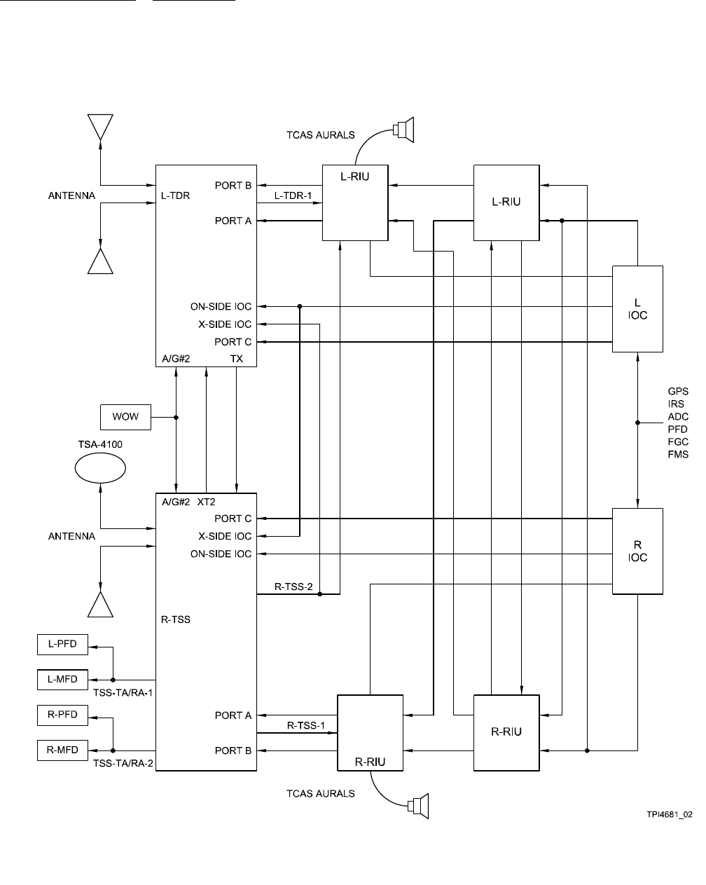
system components 523-0809018
Figure 2-18. Traffic Surveillance System, External Block Diagram
2-54
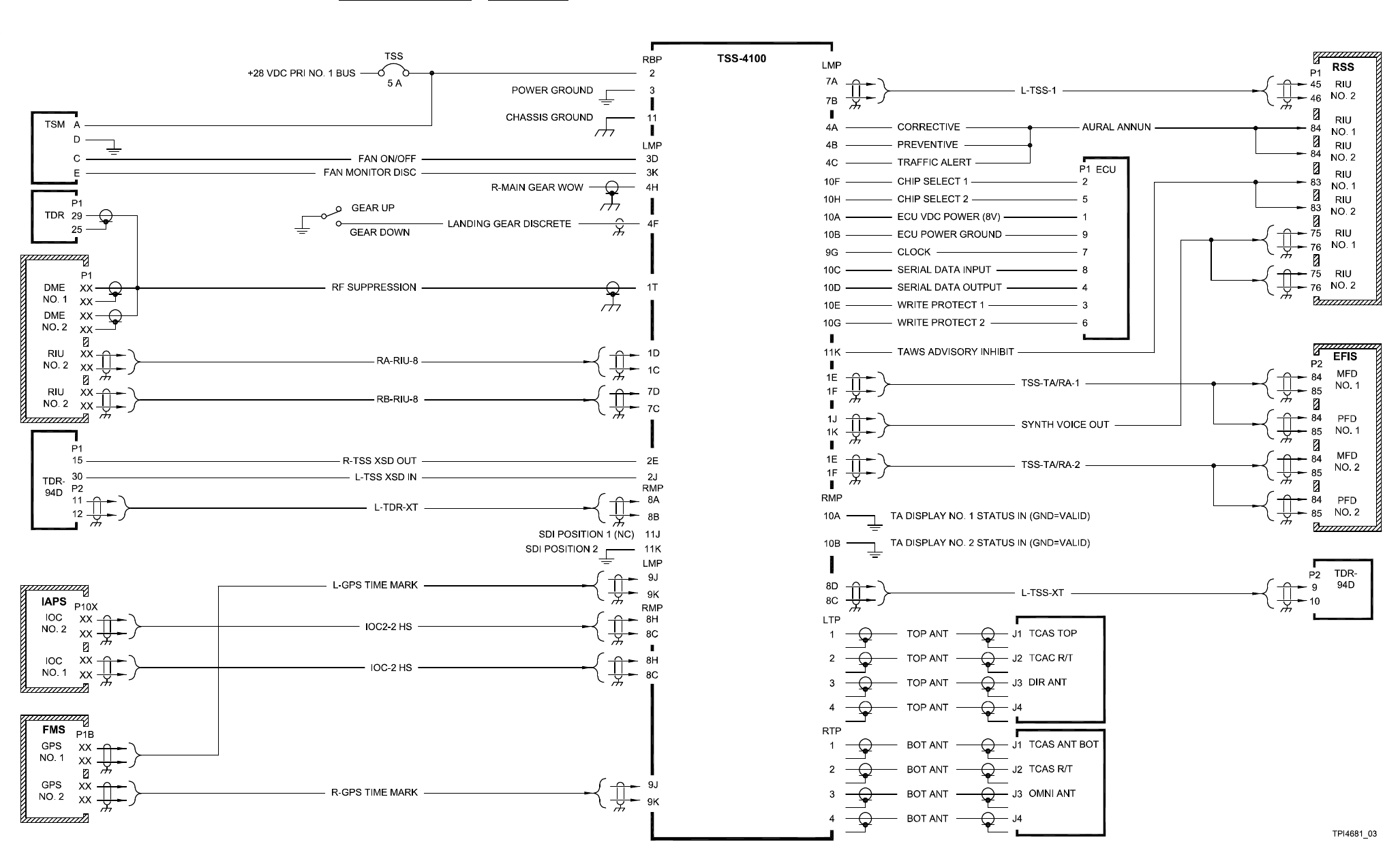
system components 523-0809018
Figure 2-19. Traffic Surveillance System, TSS-4100 No. 1, External Simplified Schematic
2-55/(2-56 Blank)
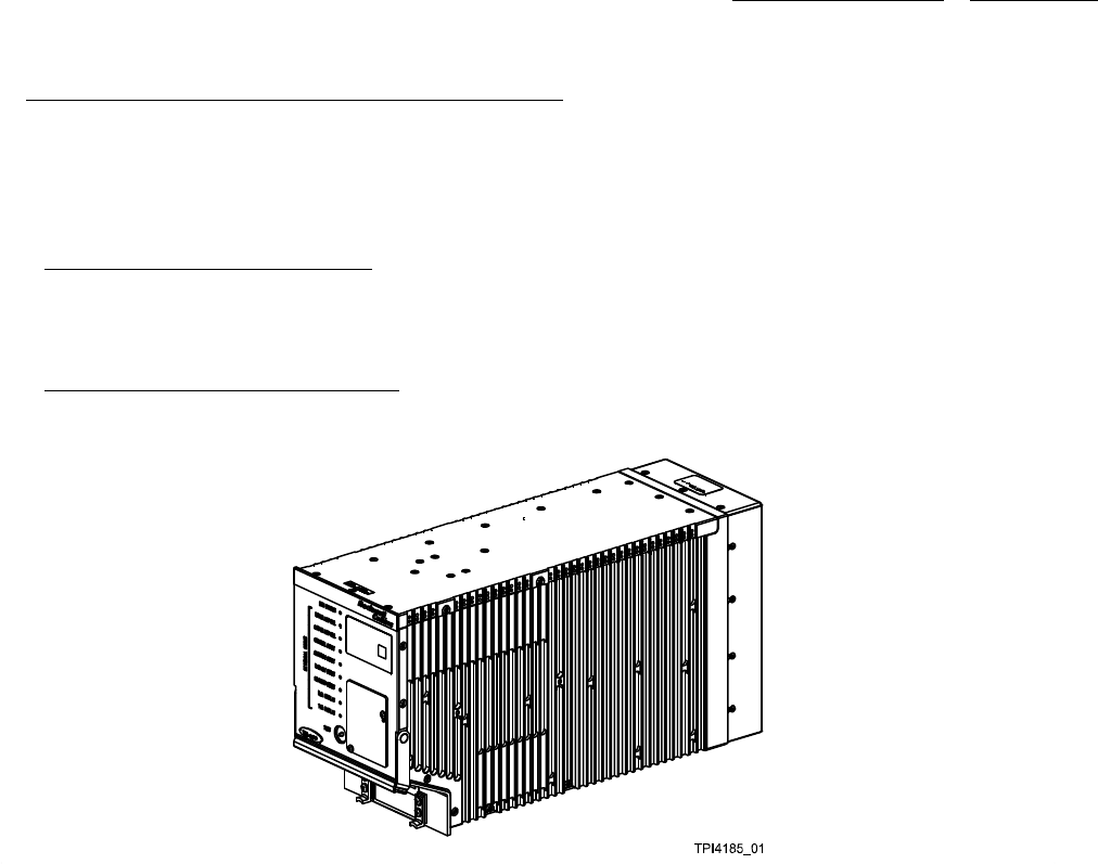
system components 523-0809018
2.14. TRAFFIC SURVEILLANCE SYSTEM, TSS-4100, DATA.
The TSS-4100 Traffic Surveillance System is a major component of an aircraft traffic system. The TSS-4100 operates on 28 V dc.
It contains all circuits necessary for computing, transmitting, and receiving functions of the TSS and interfacing with a transponder,
antennas, and displays. The TSS LRU and Traffic Surveillance System Application (TSSA) work together to provide TCAS, Mode
S transponder, and ADS-B capability in one LRU. The TSS, TSSA, and Traffic Surveillance Mount (TSM) are described in this
section.
2.14.1. TSS-4100 Antenna Requirements.
The TSS-4100 requires two antennas. One antenna is mounted on the fuselage on top of the aircraft. The other antenna is mounted
on the fuselage on the bottom of the aircraft. The top antenna is a TSA-4100 directional antenna. The bottom antenna can either be
a second TSA-4100 antenna, or it can be an omnidirectional antenna such as the TRE-930.
2.14.2. TSS-4100 and TSM-4100 Illustration.
Refer to Figure 2-20 for an illustration of the TSS-4100. Refer to Figure 2-21 for an illustration of the TSM-4100.
Figure 2-20. TSS-4100
2-57
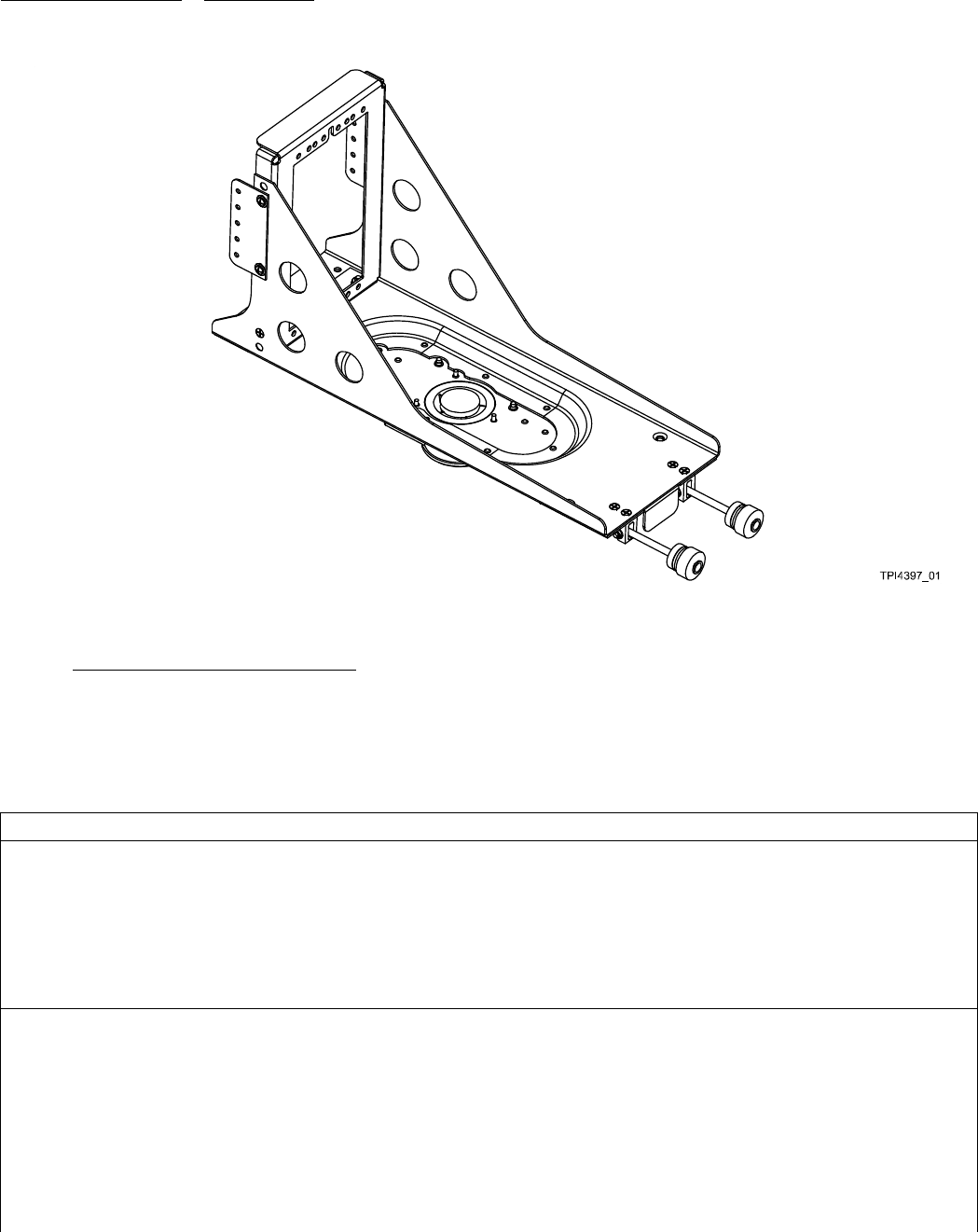
system components 523-0809018
Figure 2-21. TSM-4100
2.14.3. TSS-4100 Mating Connector Data.
Figure 2-22 shows a mating connector pictorial for the TSS-4100. Each connector shows pin locations to aid the troubleshooting
effort. Refer to the interconnect wiring diagram in the appendix. Table 2-7 shows the mating connector hardware and tooling for
the TSS-4100.
Table 2-7. TSS-4100 Mating Connector Hardware and Tooling.
TSS-4100 HARDWARE/TOOLING
Mating connector kit: CPN 628-8661-001 (qty 2)
Connector: 60-pin Thinline II, CPN 859-3477-510
Contacts: Standard Size 22 pins (RADIALL 620200)
Contacts: CPN 372-2514-180 (insulation from 1.27 mm (0.050 in) to 2.03 mm (0.080 in) diameter)
TNC connector: Automatic 301-T2100N, CPN 357-7351-010 (qty 2)
Mating connector: ARINC 600, Cannon BKAD3-67404-55, CPN 370-0501-050
Contacts (size 12): Cannon 031-1308-000, CPN 370-0066-090
Insertion/extraction tool: Cannon CET 12-4, CPN not assigned
Crimp tool: MIL M22520/1-01, CPN 359-8101-010
Crimp tool positioner: MIL M22520/1-11, CPN 359-8101-120
Contacts (size 16): Cannon 031-1303-000, CPN 370-0066-080
Insertion/extraction tool: Cannon CET 16-9, CPN 371-8445-080
2-58

system components 523-0809018
Table 2-7. TSS-4100 Mating Connector Hardware and Tooling. - Continued
TSS-4100 HARDWARE/TOOLING
Crimp tool: MIL M22520/1-01, CPN 359-8101-010
Crimp tool positioner: MIL M22520/1-02, CPN 359-8101-020
Contacts (size 20): Cannon 031-1302-000, CPN 370-0066-070
Insertion/extraction tool: Cannon CIET 20HDL, CPN 371-8445-040
Crimp tool: MIL M22520/2-01, CPN 359-8102-010
Crimp tool positioner: MIL M22520/2-08, CPN 359-8101-080
Contacts (size 22): Cannon 030-2259-000, CPN 370-0066-060
Insertion/extraction tool: Cannon CIET 22, CPN 371-8445-020
Crimp tool: MIL M22520/2-01, CPN 359-8102-010
Crimp tool positioner: MIL M22520/2-23, CPN 359-8102-130
TNC connector (qty 8): Cannon 349-1046-000, CPN 370-0066-220
Contact, coaxial RG-178 (qty 2): Cannon 249-2080-000, CPN 370-0055-100
2-59
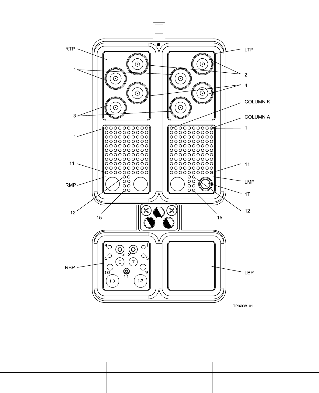
system components 523-0809018
Figure 2-22. TSS-4100 Mating Connectors
2.14.3.1. TSS-4100 Mating Connector Pins and Functions follow:
Table 2-8. TSS-4100 Mating Connector Pins and Functions, Power, Ground, Suppression.
Pin Name Connector Pin
+ 28 VDC Power In RBP 2
Power Return RBP 3
2-60

system components 523-0809018
Table 2-8. TSS-4100 Mating Connector Pins and Functions, Power, Ground, Suppression. - Continued
Pin Name Connector Pin
Chassis Ground RBP 11
Suppression Coax - coaxial insert in the
bottom corner of LMP
LMP 1T
Table 2-9. TSS-4100 Mating Connector Pins and Functions, ARINC 429 Input.
Pin Name Connector Pin A Pin B
Control A LMP 1D 1C
Control B LMP 7D 7C
Control C RMP 1D 1C
IAPS #1 (on-side) LMP 8H 8G
IAPS #2 (cross-side) RMP 8H 8G
GPS #1 LMP 6H 6G
GPS #2 RMP 2H 2G
XT2 (TDR to TSS) (or ADLP) RMP 8A 8B
Data Load LMP 7J 7K
CMU #1 (Provision) LMP 8J 8K
CMU #2 (Provision) RMP 8J 8K
ADS-B #1 (Provision) LMP 7E 7F
ADS-B #2 (Provision) LMP 7H 7G
A768 Future (Provision) RMP 7D 7C
Table 2-10. TSS-4100 Mating Connector Pins and Functions, ARINC 429 Output.
Pin Name Connector Pin A Pin B
TSS-1 LMP 7A 7B
TSS-2 LMP 1A 1B
TSS-3 (Data Load) RMP 1A 1B
TA/RA-1 LMP 1E 1F
TA/RA-2 RMP 1E 1F
TX2 (TSS to TDR) (or ADLP) RMP 8D 8C
ADS-B #1 (Provision) LMP 9E 9F
2-61

system components 523-0809018
Table 2-10. TSS-4100 Mating Connector Pins and Functions, ARINC 429 Output. - Continued
Pin Name Connector Pin A Pin B
CMU (Provision) RMP 9E 9F
General Purpose #1
(Provision)
LMP 9D 9C
Table 2-11. TSS-4100 Mating Connector Pins and Functions, GPS Time Mark Input.
Pin Name Connector Pin + Pin -
GPSTimeMark#1(On-side) LMP 9J 9K
GPS Time Mark #2
(Cross-side)
RMP 9J 9K
Table 2-12. TSS-4100 Mating Connector Pins and Functions, Discrete Input (Gnd = Active).
Pin Name Conn Pin Pin Name Conn Pin
Spare LMP 2H Advisory
Inhibit #3
LMP 11J
XTDR Active
(from XTDR)
LMP 2J Advisory
Inhibit #4
LMP 11K
Extended
Squitter Disable
LMP 2K Advisory
Inhibit #1
LMP 10J
Perf Limit LMP 3E Advisory
Inhibit #2
LMP 10K
Simulator
Enable
LMP 3F Shop Mode
Enable
RMP 6A
Air/Gnd(F) #1 LMP 3G ATE Discrete In
(Spare)
RMP 6B
Spare LMP 3H TA Display
Va l i d # 1
RMP 10A
Spare LMP 3J TA Display
Va l i d # 2
RMP 10B
Fan Monitor LMP 3K RA Display
Va l i d # 1
RMP 10C
Spare LMP 4F RA Display
Va l i d # 2
RMP 10D
Air/Gnd(F) #2 LMP 4H Burst Tune
Select
RMP 10E
Spare LMP 4J Control Port
Select 0
RMP 10F
2-62

system components 523-0809018
Table 2-12. TSS-4100 Mating Connector Pins and Functions, Discrete Input (Gnd = Active). - Continued
Pin Name Conn Pin Pin Name Conn Pin
Climb Inhibit
#1
LMP 11A Control Port
Select 1
RMP 10G
Climb Inhibit
#2
LMP 11B Advisory
Annun Cancel
RMP 10H
Climb Inhibit
#3
LMP 11C Spare RMP 10J
Climb Inhibit
#4
LMP 11D Data Load
Enable
RMP 10K
Increase Climb
Inh #1
LMP 11E Program Pin
Common
RMP 11H
Increase Climb
Inh #2
LMP 11F Source
Destination
Identifier (SDI)
Position 1
RMP 11J
Increase Climb
Inh #3
LMP 11G SDI Position 2 RMP 11K
Increase Climb
Inh #4
LMP 11H
Ctrl Port:
Ctrl
Port
Sel 0
Ctrl
Port
Sel 1 SDI code:
SDI
Pos 1
SDI
Pos 2
Gnd Open Ctrl Bus A Gnd Open Side 1 - Left
Open Open Ctrl Bus B Open Gnd Side 2 - Right
X Gnd Ctrl Bus C Open Open Not Used
Gnd Gnd Not Used
Table 2-13. TSS-4100 Mating Connector Pins and Functions, Discrete Output (Gnd = Active).
Pin Name Conn Pin Pin Name Conn Pin
TSS Active (to
XTDR)
LMP 2E Test Data 1 RMP 6D
Spare +28/Open LMP 2F Test Data 2 RMP 6E
Spare LMP 2G Test Data 3 RMP 6F
Visual Annun C LMP 3A Test Data 4 RMP 6G
Visual Annun P LMP 3B Test Data 5 RMP 6H
Visual Annun
TA
LMP 3C Test Data 6 RMP 6J
Fan Off
(100ma)
LMP 3D Test Data 7 RMP 6K
2-63

system components 523-0809018
Table 2-13. TSS-4100 Mating Connector Pins and Functions, Discrete Output (Gnd = Active). - Continued
Pin Name Conn Pin Pin Name Conn Pin
Aural Advisory
C
LMP 4A Test Data
Address 0
RMP 7G
Aural Advisory
P
LMP 4B Test Data
Address 1
RMP 7H
Aural Advisory
TA
LMP 4C Test Read RMP 7J
Test Data 0 RMP 6C Test Write RMP 7K
Table 2-14. TSS-4100 Mating Connector Pins and Functions, Audio Output.
Pin Name Connector Pin Hi Pin Lo
Audio #1 LMP 1J 1K
Audio #2 RMP 1J 1K
Table 2-15. TSS-4100 Mating Connector Pins and Functions, ECU Interface.
Pin Name Connector Pin
Clock Out to ECU LMP 9G
Power Out to ECU LMP 10A
Power Return from ECU LMP 10B
Serial Data In from ECU LMP 10C
Serial Data Out to ECU LMP 10D
Write Enable #1 Out to ECU LMP 10E
Enable #1 Out to ECU LMP 10F
Write Enable #2 Out to ECU LMP 10G
Enable #2 Out to ECU LMP 10H
2.14.4. TSS-4100 Outline and Mounting Dimensions.
Refer to Figure 2-23 for an illustration of the TSS-4100 Outline and Mounting Dimensions. Refer to Figure 2-24 for an illustration
of the TSM-4100 Outline.
2-64
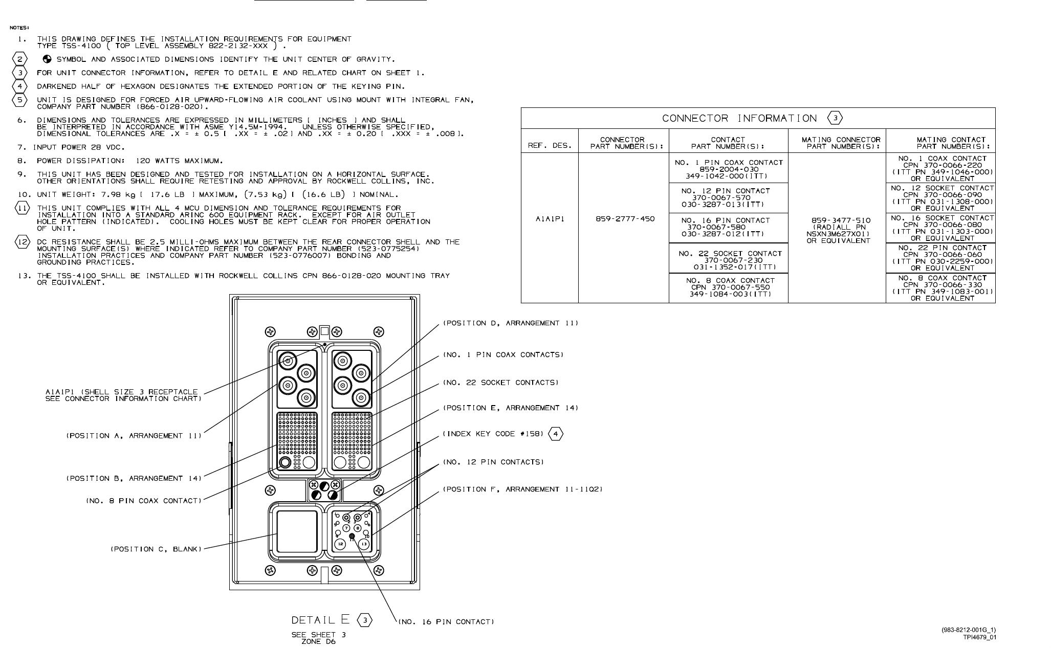
system components 523-0809018
Figure 2-23. TSS-4100 Traffic Surveillance System, Outline and Mounting Dimensions (Sheet 1 of 3)
2-65/(2-66 Blank)
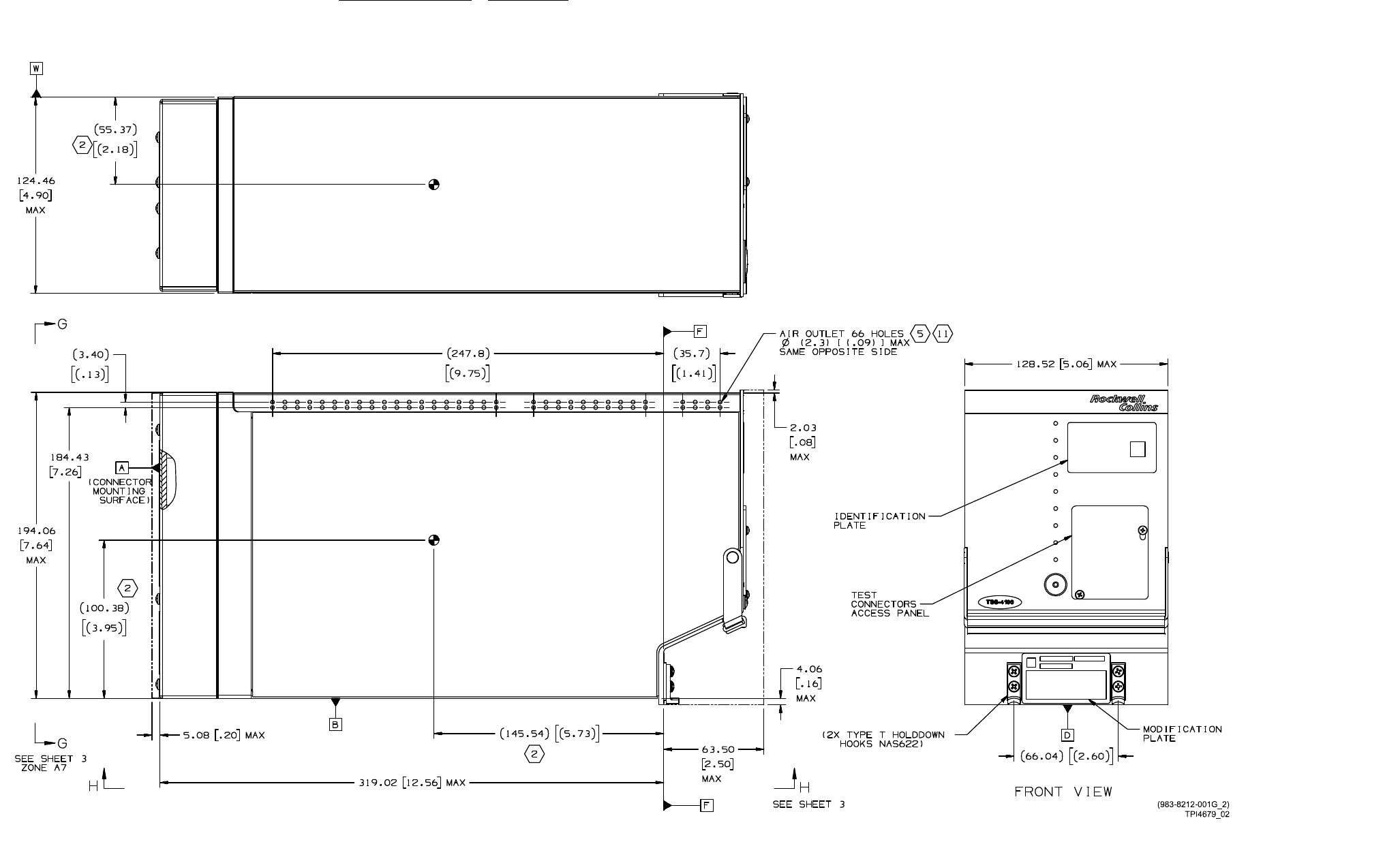
system components 523-0809018
Figure 2-23. TSS-4100 Traffic Surveillance System, Outline and Mounting Dimensions (Sheet 2 of 3)
2-67/(2-68 Blank)
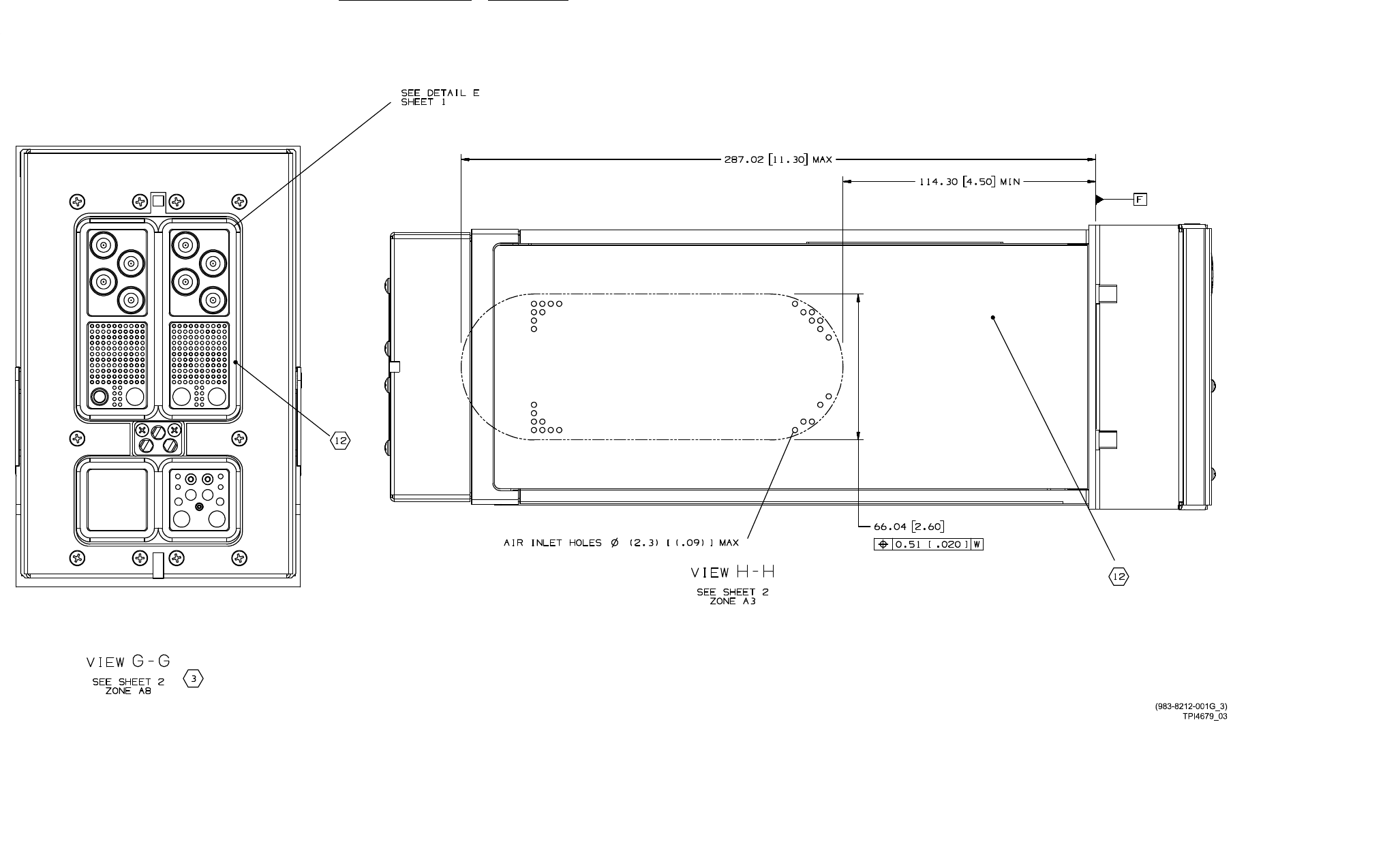
system components 523-0809018
Figure 2-23. TSS-4100 Traffic Surveillance System, Outline and Mounting Dimensions (Sheet 3 of 3)
2-69/(2-70 Blank)
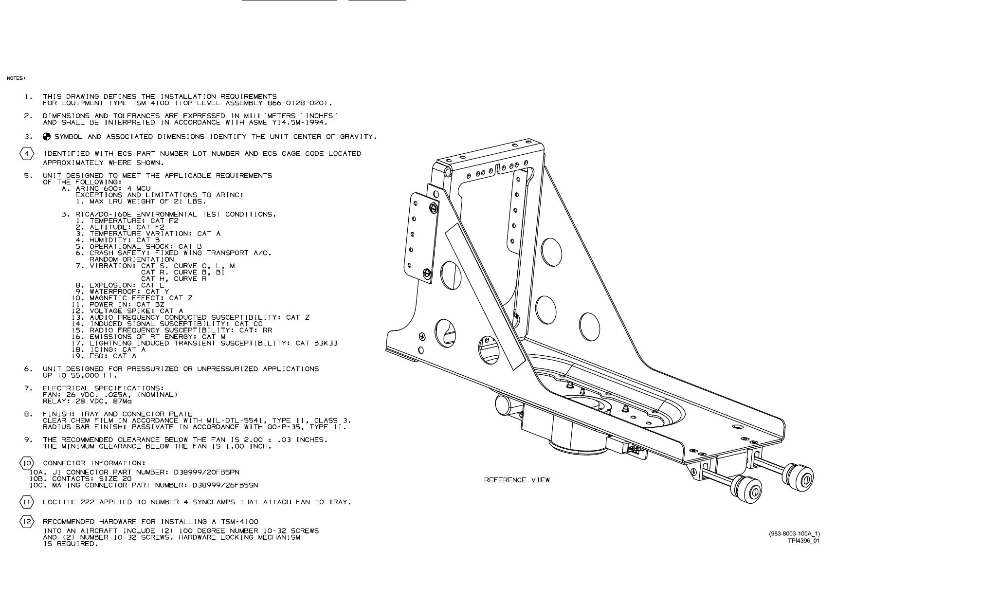
system components 523-0809018
Figure 2-24. TSM-4100 Traffic Surveillance Mount, Outline (Sheet 1 of 3)
2-71/(2-72 Blank)
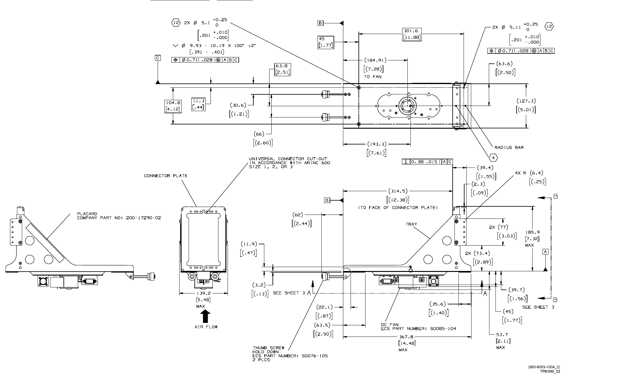
system components 523-0809018
Figure 2-24. TSM-4100 Traffic Surveillance Mount, Outline (Sheet 2 of 3)
2-73/(2-74 Blank)
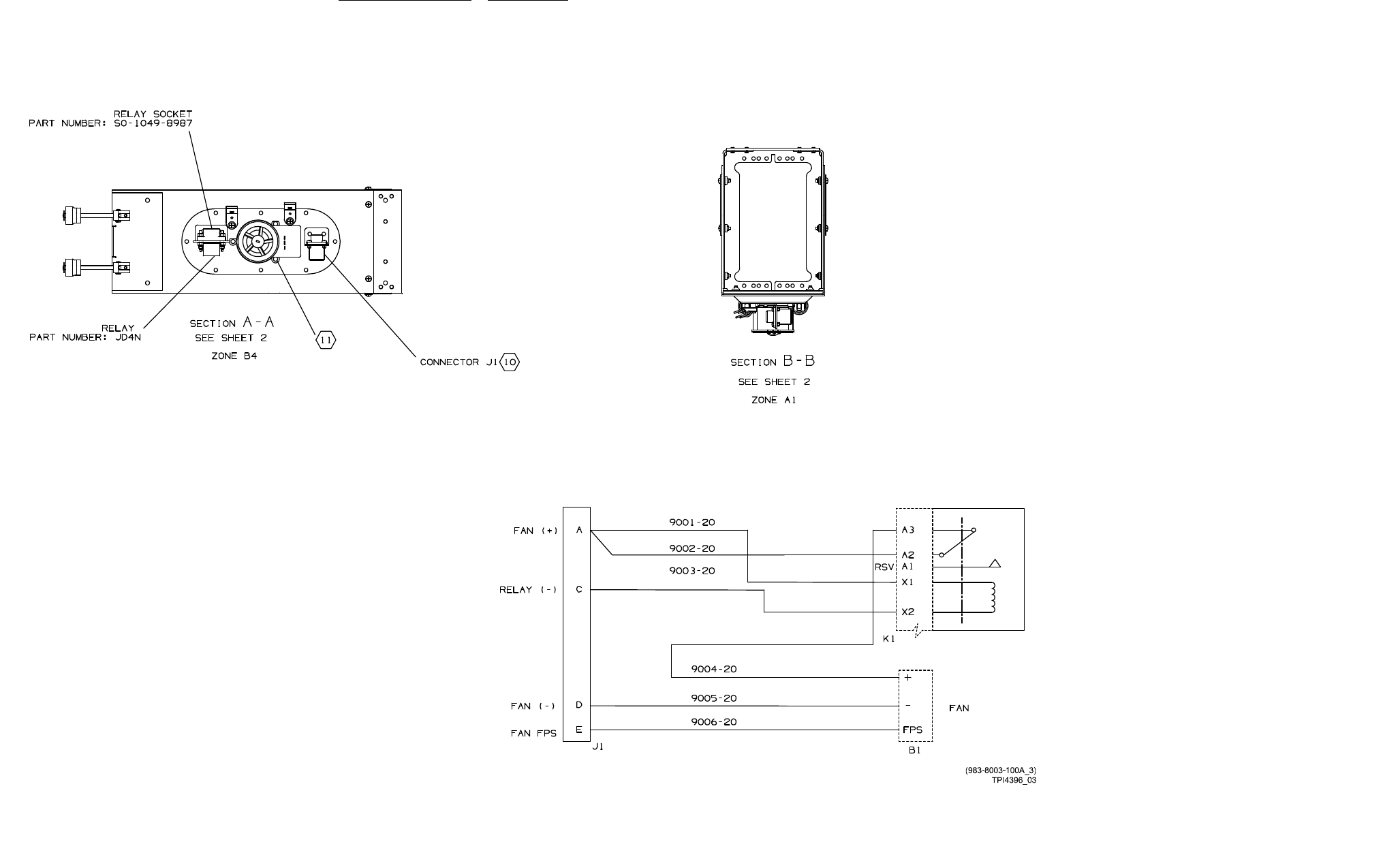
system components 523-0809018
Figure 2-24. TSM-4100 Traffic Surveillance Mount, Outline (Sheet 3 of 3)
2-75/(2-76 Blank)

system components 523-0809018
2.14.5. Cabling Considerations.
For the TSS-4100:
• Shield wires shall be no greater than 4 inches in length.
• The wires from the TSS to the ECU shall be no greater than one meter in length.
• The SDI strap shall be no greater than 6 inches in length.
• The length of the wires from the TSS to the TSM shall be no greater than 18 inches in length.
• The circuit breaker for the TSS should be rated for 7.5 Amps.
2.14.6. Installation and Removal.
Make sure that the aircraft battery master switch is turned off before installing any equipment, mounts, or inter-
connect cables.
NOTE
The resistance between the TSS-4100 and the rear contact shell and mounting surfaces must not be greater than
2.5 milliohms.
The TSS-4100 is rack mounted in the TSM-4100.
2.14.6.1. Installation. The procedure to install the TSS-4100 follows:
a. Remove electrical power from the aircraft.
b. Slide the unit into the mount until the mating connectors are fully engaged.
c. Position the knurled knobs (on the front of mount) to engage the unit holddown hooks. Tighten the knurled knobs to secure the
unit to the mount. Safety-wire the knurled knobs.
2.14.6.2. Removal. The procedure to remove the TSS-4100 follows:
a. Remove electrical power from the aircraft.
b. Remove the safety wire and loosen the knurled knobs that secure the unit to the mount.
c. Slide the unit straight out to disconnect it from the mount connectors.
2.14.7. Internal Theory of Operation.
The TSS-4100 Processing unit provides the main processing, system I/O, and traffic RF functions for the system in an ARINC 600 4
MCU Line Replaceable Unit (LRU). The paragraphs that follow outline the functions of the main assemblies. Refer to Figure 2-25
for an internal block diagram of the TSS-4100.
2.14.7.1. Power Supply Assembly. Power supply assembly develops the primary 12 V dc bus voltage from the 28 V dc aircraft
power. The power supply assembly consists of a power supply circuit card and a storage capacitor assembly which enables the
TSS-4100 to continue operating through momentary power interruptions. The power supply assembly supplies +31.6 V dc to the
transmitter module and +12 V dc to the other circuit cards and sub-assemblies of the TSS-4100.
2.14.7.2. System Processor Input / Output Assembly. The System I/O Circuit Card (SysIO) controls almost all of the input
and output between the TCAS/transponder function and other aircraft systems. SysIO outputs display data, aural messages, fault
information, aircraft system discretes, and data logging outputs. SysIO receives data used by the TCAS/transponder card and per-
forms most of the source selection logic. SysIO manages the data loading of the unit and of the attached ECU. SysIO is responsible
for communications with the ECU and for monitoring of an external fan.
2.14.7.3. Traffic Receiver Assembly. The traffic receiver assembly consists of three circuit card assemblies, the RF switch,
receiver circuits and digital signal processing circuits for the ACAS/transponder function. The RF switch circuit controls the selec-
tion function for the top and bottom antennas, antenna element selection and the transmit/receive switch function. There are eight
2-77

system components 523-0809018
parallel antenna ports, four each for the top and bottom antennas on the aircraft. Each port represents a beam heading: fore, aft,
port, starboard. The transmit port from the power amplifier is switched to one of these eight antenna ports. The receiver paths on the
RF switch include fixed-gain, low-noise amplifiers and band-pass filtering. Each of the eight antenna ports feeds a separate receiver
path. The receiver circuits down-convert the band-pass filtered L-band frequencies provided through the switch card to intermediate
frequencies, provide additional filtering and provide receiver gain. There are 16 parallel transponder receiver paths; eight each high
and low gain. There are four parallel TCAS receiver channels, with switchable high/low gain. These 16 Transponder and four TCAS
signals become 20 parallel high speed Analog to Digital Converter channels to the signal processor circuit card. The TSS design
also supports a 5 antenna port installation where top ports one thru four are connected to a directional antenna and bottom port 1 is
connected to an omni-directional antenna. Bottom ports two thru four would not be used in this configuration. The signal processing
circuits correlate and track the replies of Mode S and Mode C transponders for the TSS-4100 TCAS function. The signal processing
circuits use these replies to calculate intruder aircraft range, altitude and bearing. From this calculation, the signal processing circuits
also develop resolution and traffic advisory data. Resolution Advisories (RA) and Traffic Advisories (TA) are sent to the aural and
visual displays. The signal processing circuits also receive and prepare responses to ATCRBS and Mode S interrogations for the
TSS-4100 transponder function.
2.14.7.4. Traffic Transmitter Assembly. The traffic transmitter module consists of a modulator circuit card and a power am-
plifier circuit card. The Traffic Transmitter Module receives serial frequency tuning data and a set of digital commands from the
digital signal processor that specify the desired pulses to be sent. The modulator circuit card then generates the appropriate ACAS
Differential Phase Shift Keying (DPSK) modulation, Mode-C whisper shout, or transponder interrogation output that will be sent to
the ATC/ACAS antenna. The modulator card implements a power control loop so that the drive to the power amplifier is varied to
achieve the desired output power. Modulation is produced in a quadrature modulator, allowing amplitude only (pulse), PPM, and
the PSK waveform to be produced. The modulator drive level changes on a 16.667 nsec (60.000 MHz) clock, allowing tight control
of the rise and fall times of the pulse. The power amplifier circuit amplifies the transmit signals before the signals are sent through
the RF switch to the antenna.
2.14.7.5. TSS-4100 Cooling Considerations. Because the TSS-4100 was tested without the TSM-4100 for the loss of cooling
test, the TSS-4100 must be installed with cooling. If the TSM-4100 is not used, equivalent cooling must be supplied or a thermal
analysis of the installation must be done to show that the TSS-4100 will remain within its operating temperature range (-55 to +80
degrees C).
2.14.7.5.1. If the traffic module of the TSS detects that the transmitter is getting too hot, the TSS-4100 will put itself into standby
and declare itself failed.
2-78
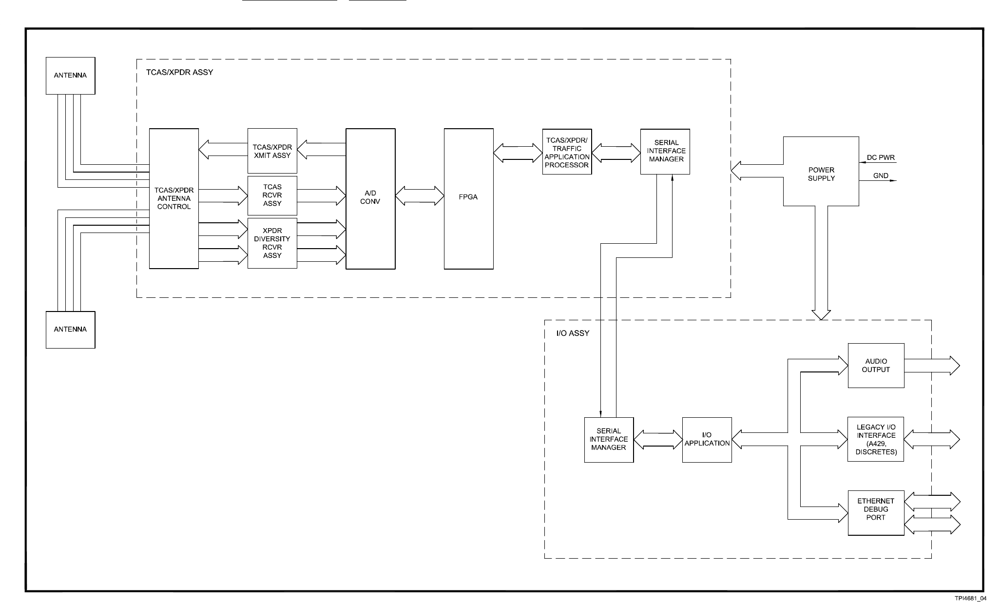
system components 523-0809018
Figure 2-25. Traffic Surveillance System, TSS-4100, Internal Block Diagram
2-79/(2-80 Blank)

523-0809018
CHAPTER 3
Operation
3.1. INTRODUCTION.
NOTE
This section is not intended to be a pilot’s guide, but is written to provide a basic knowledge and understanding of
operating procedures for this system. For detailed data about the controls and displays of a specific airplane, refer
to the Operator's Guide for that airplane.
Line Replaceable Units (LRU) with specific controls and displays are described in this section. However, the
Traffic Surveillance System (TSS) can be controlled by any Transponder (TDR) / Traffic Alert Collision Avoid-
ance System (TCAS) control unit, and TCAS traffic. Also, Traffic Advisory (TA) / Resolution Advisory (RA)
information can be shown by any ARINC 735A standard display.
Only basic controls and indicators, plus those related to TRAFFIC operation, are discussed in this manual.
This section shows the typical operating controls and displays of a Traffic Surveillance System. Tables describe each control or
displayinsufficient detail so that the flight-line technician can operate the equipment and troubleshoot the complete system.
3.2. GENERAL.
This chapter of the Traffic Surveillance System installation manual contains examples and a description of the controls and indicators
listed below:
•Traffic Display on an Adaptive Flight Display (AFD)
•RADisplaysonanAFD
• Top Level Radio Page on a Radio Tuning Unit (RTU) or a Control Display Unit (CDU)
• TCAS Control Page on an RTU or CDU
• Transponder Control Page on a CDU or an RTU.
3-1
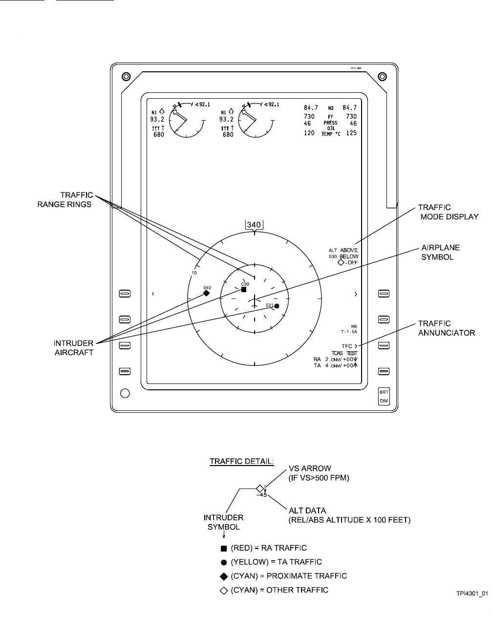
operation 523-0809018
Figure 3-1. Traffic Display (AFD-3010/3010E), TRAFFIC Page
3-2

operation 523-0809018
Table 3-1. Tra ffic Display (AFD-3010/3010E), TRAFFIC Page.
CONTROL OR
DISPLAY FUNCTION/DESCRIPTION
Refer to Figure 3-1.
TRAFFIC map The TSS traffic symbology is available for display on the display. Push the Traffic (TFC) line
select key to show the TSS traffic overlay on the Horizontal Situation Indicator (HSI), arc,
or Present Position (PPOS) Map formats. This map is a dynamic, heading-up pictorial that
shows nearby transponder-equipped aircraft. This screen shows traffic symbols that alert the
crew to potential and predicted collision threats. A traffic only format, along with the standard
traffic overlay option, is available from the PPOS Map using either a LOWER FORMAT or
the TFC line select key. The traffic only format erases all non-trafficsymbols.
TRAFFIC RANGE
RINGS
Three range rings provide a distance measuring scale. These rings show distance from the
aircraft. Turn the RANGE knob on the Display Control Panel (DCP) to select the desired
full-scale display range. The outer ring is a full-intensity circle with a tic mark every 30
degrees. This ring represents the selected full-scale range. A numeric distance label shows
by the outer range ring. The middle ring is a half-intensity circle with a tic mark every 30
degrees. This ring marks the half-scale range (not shown when full-scale range is 5 miles).
The inner ring consists of (only) tic marks every 30 degrees. This ring normally marks a range
of 3 miles, but blanks when the full-scale range is more than 25 miles.
INTRUDER AIRCRAFT INTRUDER AIRCRAFT are shown with an INTRUDER SYMBOL, Altitude (ALT) DATA,
and a VS ARROW.
INTRUDER SYMBOL Four kinds of intruder aircraft symbols may show.
NOTE
If a Traffic Advisory (TA) or TCAS Resolution Advisory (RA) intruder is detected that
is beyond the selected display range, (only) half of the TA or RA traffic symbol shows.
This half-symbol appears on the outer ring at the appropriate bearing.
• The cyan open-diamond symbol shows an aircraft that is in the protected air space volume,
but is not considered to be a collision threat.
• The cyan solid-diamond symbol is a proximate traffic symbol. This symbol shows an aircraft
that is nearby (<1200 feet relative altitude), but not close enough to be considered advisory
traffic.
• The yellow solid-circle is a TA traffic symbol. This is a traffic advisory that means the in-
truder aircraft is a potential threat.
• The red solid-square is an RA traffic symbol. This is a resolution advisory that means the
intruder aircraft is an immediate threat. Take corrective or preventive action to maintain
minimum air space separation. RA traffic symbols are shown only with traffic.
VS ARROW If the vertical trend rate of the intruder is greater than 500 feet per minute, the VS arrow
shows. The arrow points up if the intruder is climbing, and down if descending.
3-3

operation 523-0809018
Table 3-1. Tra ffic Display (AFD-3010/3010E), TRAFFIC Page. - Continued
CONTROL OR
DISPLAY FUNCTION/DESCRIPTION
TRAFFIC MODE
DISPLAY
The traffic mode display shows the traffic altitude above/below limits selected, the aircraft
altitude, and other traffic selected off. This window defines a zone of vertical air space relative
to the aircraft. Intruders into this zone are tracked and considered potential threats. Four
selections are possible, and the selected option on the CDU is enlarged.
• NORM: The protection window is 2700 feet above and 2700 feet below the aircraft.
• ABOVE: The protection window is 9900 feet above and 2700 feet below the aircraft.
• BELOW: The protection window is 2700 feet above and 9900 feet below the aircraft.
• ABOVE/BELOW: The protection window is 9900 feet above and 9900 feet below the air-
craft.
When Absolute (ABS) altitude is selected, the airplane absolute altitude shows in hundreds of
feet. This field is blank when Relative (REL) altitude is selected.
AIRPLANE SYMBOL This symbol is a reference that represents the airplane. This symbol is used to visualize the
relative positions of intruder aircraft. The airplane symbol is stationary and always shows in
the center of the screen. Intruder traffic symbols show and move about the screen as long
as valid bearing information is received, and the aircraft is within the selected range and
relative altitude window.
TRAFFIC
ANNUNCIATOR
Push the TFC line select key to add or remove the traffic overlay from the arc or present
position map formats. The selected traffic operating mode annunciates below the TFC
annunciator. Select the traffic mode from the TRAFFIC CONTROL page on the CDU or
Radio Tuning Unit (RTU). When TA/RA mode is selected, the TFC annunciator field is blank.
TA and RA symbols may show. TA/RA mode is inhibited when the aircraft is on the ground.
When Standby (STBY) mode is selected, TRAFFIC OFF (or TCAS OFF) annunciates in
white. When TA mode is selected, TA ONLY annunciates in white (no intruders) or flashes
yellow (TA intruder detected). RA symbols are not shown in this mode. TRAFFIC FAIL (or
TCAS FAIL) annunciates if the display is not receiving the TRAFFIC bus. TRAFFIC TEST
(or TCAS TEST) annunciates when the TSS is in test mode.
No bearing table This two line table, shown below the TRAFFIC operating mode, automatically shows when
the TSS detects an RA or TA intruder, but does not receive valid bearing information. This
table shows data for the first two TA/RA intruders for which bearing information is not
available. Each line lists the RA/TA advisory type, distance/altitude, and a VS trend arrow (if
trend is more than 500 feet/minute). The lines are red (RA) or yellow (TA).
3-4
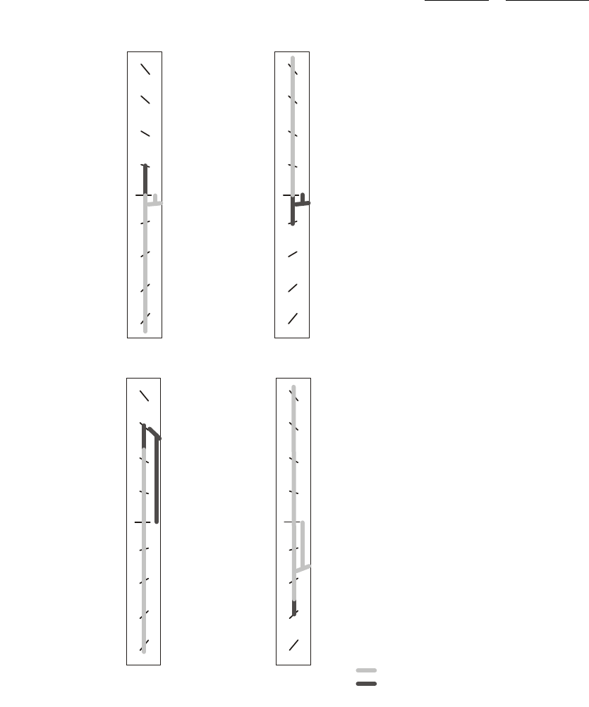
operation 523-0809018
TPI4301_02
2
2
2
2
2
2
2
2
1
1
1
1
1
1
1
1
4
4
4
4
4
4
4
4
CLIMB
PREVENTIVE
DESCEND
CORRECTIVE
DESCEND
PREVENTIVE
CLIMB
CORRECTIVE
= RED
= GREEN
Figure 3-2. Resolution Advisory Display (AFD), TCAS II Fly-To Commands
3-5
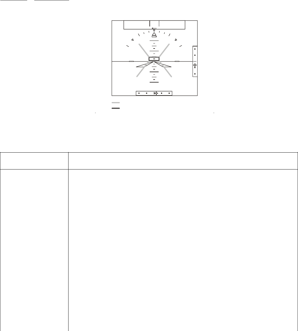
operation 523-0809018
TPI4301_03
2O
1O
1O
2O
ALTV
LNV1
APYD VPATH
= RED
= GREEN
Figure 3-3. Resolution Advisory Display (AFD), Pitch Cues
Table 3-2. Resolution Advisory Display (AFD), TCAS II Fly-To Commands and Pitch Cues.
CONTROL OR
DISPLAY FUNCTION/DESCRIPTION
RefertoFigure3-2foranillustrationofFly-ToCommandsonanRAVerticalSpeedindicator.
RA Fly-To Commands NOTE
The message TRAFFIC shows in red below the vertical speed scale on the PFD when the
system detects RA traffic. The message shows in yellow below the vertical speed scale
when the system detects TA traffic.
RA vertical speed fly-to commands show on the PFD vertical speed scale when in TA/RA
mode and a trafficconflict exists. The fly-to commands show as red and green bands. To
comply with an RA, avoid flying vertical speeds within the red-banded areas and do flythe
vertical speeds within the green-banded areas.
There are two types of RAs that show on the PFD, preventive and corrective. These are
described below:
• Preventive RAs are issued for threat traffic for which the TSS has determined current vertical
speed will resolve the threat situation. The vertical speed range to avoid shows in red on the
PFD vertical speed scale.
• Corrective RAs are issued for threat traffic for which the TSS has determined that corrective
action needs to be taken to avoid the traffic. The vertical speed range to seek (green) and
avoid (red) shows on the PFD vertical speed scale. Aural commands are issued over the
cockpit audio system.
Refer to Figure 3-3 for an illustration of RA pitch cues on an attitude indicator.
3-6

operation 523-0809018
Table 3-2. Resolution Advisory Display (AFD), TCAS II Fly-To Commands and Pitch Cues. - Continued
CONTROL OR
DISPLAY FUNCTION/DESCRIPTION
RA Pitch Cues, Attitude
Indicator
The TCAS Resolution Advisory (RA) pitch cues are shown on the PFD attitude indicator. The
pitch cues advise the pilot of the pitch attitude that is necessary to satisfy a vertical RA.
RA cues are issued by the TSS when aircraft corrective maneuvering is required in order to
avoid a potential collision. The pitch cues are shown as red avoidance zones and green flyto
zones. A yellow NO ATT RA message is shown in the TCAS data fieldwhenRApitchcues
cannot be computed or if pitch data is not in view on the PFD. The pitch cues are disabled
when an excessive attitude condition exists. When any data required to compute pitch cues is
invalid, the pitch cues are removed.
The two types of RA cues that can be issued by the TSS are preventative and corrective.
These are described above.
3-7
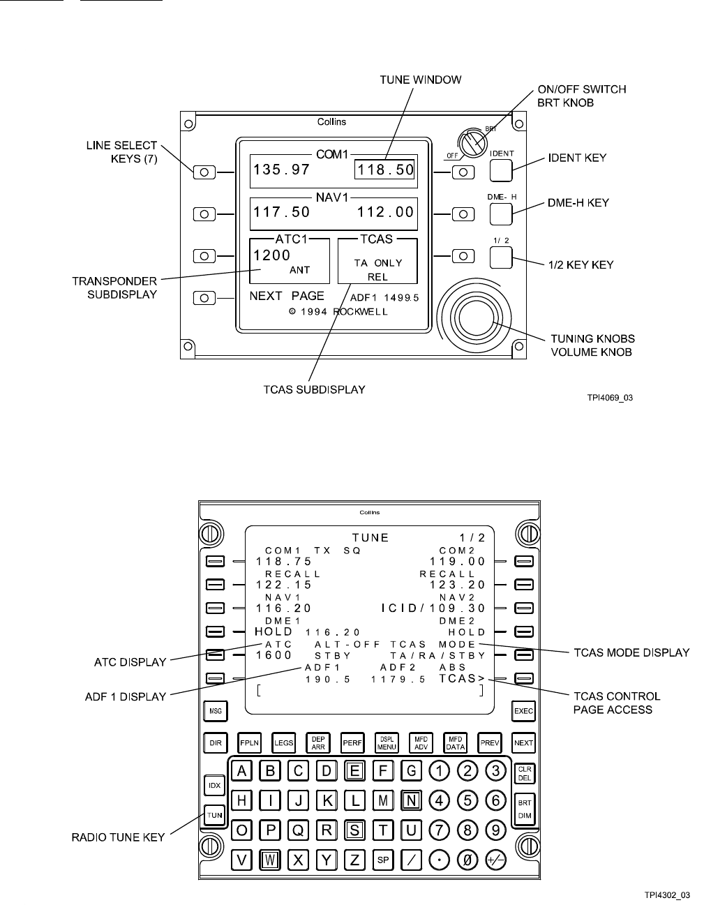
operation 523-0809018
Figure 3-4. Top Level Radio Tuning Page, RTU-42XX Radio Tuning Unit
Figure 3-5. Top Level Radio Tune Page, CDU-62XX Control Display Unit
3-8

operation 523-0809018
Table 3-3. Top Level Radio Tune Page, RTU Radio Tuning Unit or CDU Control Display Unit.
CONTROL OR DISPLAY FUNCTION / DESCRIPTION
RefertoFigure3-4forthetoplevelradiotunepageonanRTU.
Refer to Figure 3-5 for the top level radio tune page on a CDU.
NOTE
Some of the controls listed are optional and may or may not be included depending on
the installation.
LINE SELECT KEYS The RTU and CDU have several panel mounted line select keys. These are used to select
control of individual radio frequencies, presets, codes, and modes.
TCAS SUBDISPLAY (RTU) or
TCAS MODE DISPLAY
(CDU)
Displays various TCAS operating modes and selections.
TCAS CONTROL PAGE
ACCESS
(CDU only)
Push the TCAS line key to view the ATC/TCAS CONTROL page. Refer to Figure 3-7. The
selected TCAS altitude display format ABS (Absolute) or REL (Relative) also shows above
the TCAS legend.
ATC DISPLAY
(CDU only)
Set the active ATC beacon code by keying the desired beacon code onto the scratch pad line.
Then push the ATC line key to transfer this code to the selected field. If the beacon code
is valid, it shows in the data field, and the active transponder immediately responds to the
new beacon code. ALT OFF is shown to the right of the ATC legend when reply Mode A is
selected. STBY shows when standby is selected. REPLY shows when the active TDR replies
to an interrogation. IDENT shows when the IDENT line key on the ATC/TCAS CONTROL
page is pushed and the active TDR transmits. The digit to the right of the ATC legend shows
which transponder is active.
TUNE WINDOW
(RTU only)
The tune window surrounds the item selected for control.
TUNING KNOBS
(RTU only)
The tuning knobs are used to set the value shown in the tune window. When a frequency, code,
or mode is shown in the tune window, the large tuning knob controls the most significant digits,
and the small tuning knob controls the least significant digits.
VOLUME KNOB
(RTU only)
If present, the volume knob is the third (smallest diameter) knob on the knob cluster. As the
volume knob is rotated, a volume scale is displayed adjacent to the selected radio.
IDENT KEY
(RTU only)
Push the IDENT function key to transmit an Air Traffic Control (ATC) identification pulse.
When the ident feature is active, ID is shown in cyan on the ATC sub-display and on the ATC
main display page.
3-9
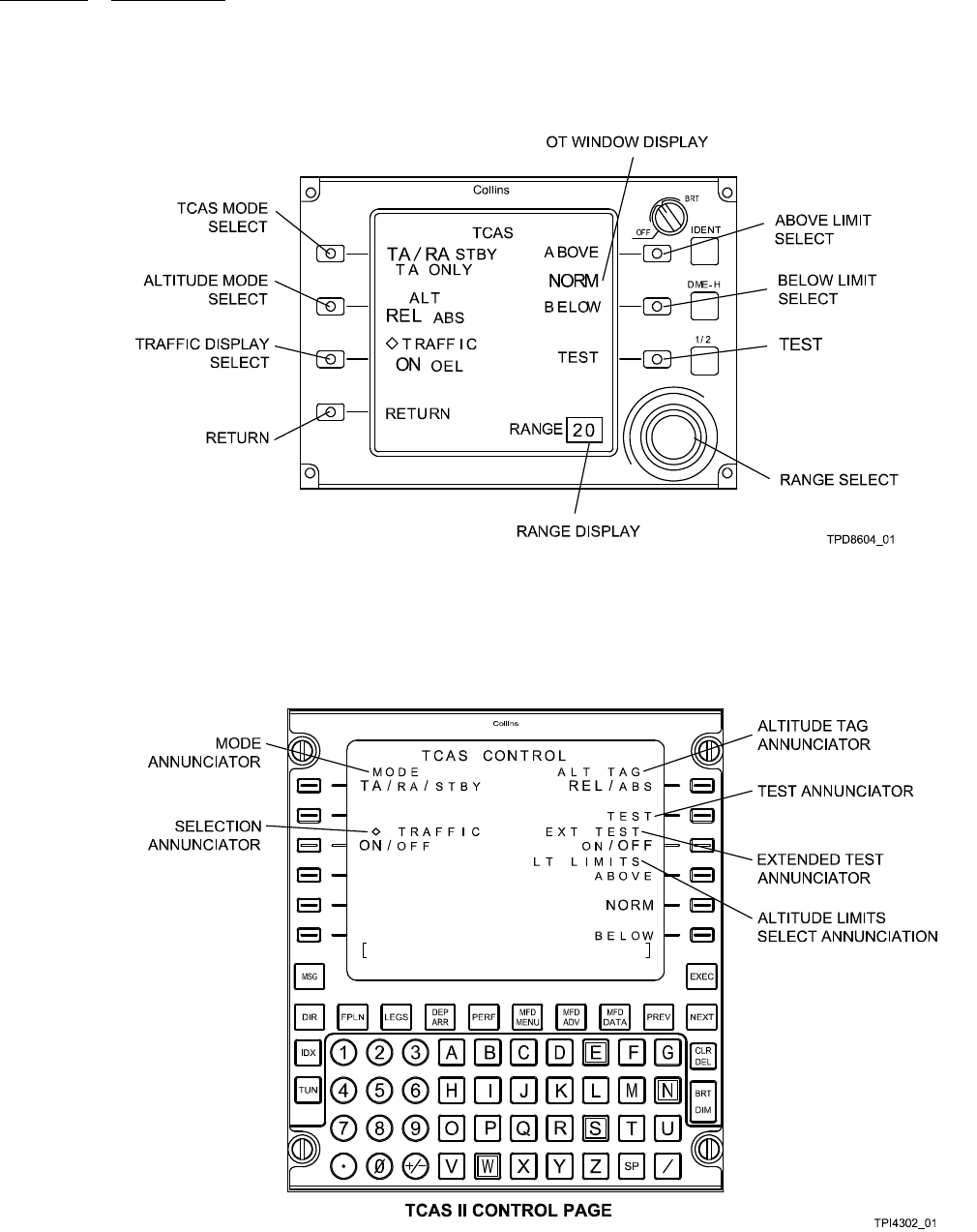
operation 523-0809018
Figure 3-6. TCAS Page, Radio Tuning Unit (RTU-42XX)
Figure 3-7. TCAS Page, Control Display Unit (CDU-62XX)
3-10

operation 523-0809018
Table 3-4. TCAS Page, Radio Tuning Unit or Control Display Unit.
CONTROL OR
DISPLAY FUNCTION/DESCRIPTION
NOTE
Some of the controls listed are optional and may or may not be included depending on the
installation.
Refer to Figure 3-6 for a typical TCAS Page on an RTU.
Refer to Figure 3-7 for a typical TCAS Page on a CDU.
TCAS CONTROL page Push the TCAS line key on the top level CDU (or RTU) page to select the TCAS CONTROL
page.
MODE ANNUNCIATOR
or MODE SELECT line
key
Push the MODE line key to to toggle through the TCAS modes:
•TA/RA(Traffic and Resolution Advisories)
• STBY (Standby)
• TA ONLY (Traffic Advisories Only).
The active mode is shown in cyan and in large letters. Open-diamond traffic is other traffic. RA
traffic, TA traffic, and proximate traffic may still show.
ALTITUDE TAG
ANNUNCIATOR or
ALTITUDE MODE
SELECT line key
Push this line select key to toggle between the altitude modes. The available modes are Rela-
tive (REL) and Absolute (ABS).
TEST ANNUNCIATOR
and line key
Push the TEST line key to initiate the TSS self-test routines. When self test is active, TEST is
annunciated in cyan and in large letters for approximately 10 seconds. When TSS self test is
initiated, the ATC self test is also initiated.
NOTE
If an extended test is an option, push and hold the TEST line select key to initiate the
extended self test.
ALTITUDE LIMITS
SELECT line keys and
OT WINDOW DISPLAY
Push the ABOVE, NORM, or BELOW line key to select the altitude range of the trafficpro-
tection window. The active altitude volume limit of Other Traffic (OT) is shown in cyan and in
large letters.
NOTE
If there is no NORM line key between the ABOVE and BELOW line keys (for example,
on the RTU shown), then NORM is selected when neither ABOVE nor BELOW are se-
lected.
The altitude limit defines a volume of vertical air space relative to the aircraft. Intruders into this
volume are tracked and considered potential threats. When NORM is selected, the protection
volume is 2700 feet above and 2700 feet below the aircraft. When ABOVE is selected, the pro-
tection volume is 9900 feet above and 2700 feet below the aircraft. When BELOW is selected,
the protection volume is 2700 feet above and 9900 feet below the aircraft. When ABOVE and
BELOW are both selected, the protection volume is 9900 feet above and 9900 feet below the
aircraft.
3-11

operation 523-0809018
Table 3-4. TCAS Page, Radio Tuning Unit or Control Display Unit. - Continued
CONTROL OR
DISPLAY FUNCTION/DESCRIPTION
SELECTION
ANNUNCIATOR or
TRAFFIC DISPLAY
SELECT
Push the adjacent line select key to set other traffic (non-threat traffic) monitoring ON (all traffic)
or OFF (threat traffic only). The active state is shown in cyan and in large letters.
RANGE SELECT (RTU
only)
Turn either tuning knob to set the display range. Clockwise rotation selects increasing ranges
and counterclockwise rotation selects decreasing ranges. Available range depends on the instal-
lation and may be either 6/12, 6/12/20/40, 3/5/10/20/40, or 5/10/20/40 (nmi).
3-12
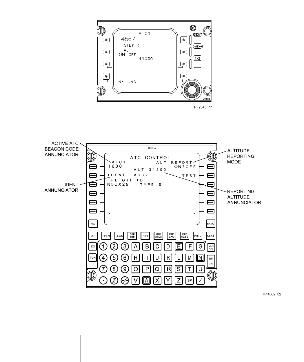
operation 523-0809018
Figure 3-8. Transponder Page, RTU-42XX Radio Tuning Unit
Figure 3-9. Transponder Page, CDU-62XX Control Display Unit
Table 3-5. Transponder Page, RTU Radio Tuning Unit or Control Display Unit.
CONTROL OR DISPLAY FUNCTION / DESCRIPTION
Figure 3-8 shows the ATC main display page on an RTU.
Figure 3-9 shows the ATC controls on a CDU.
3-13

operation 523-0809018
Table 3-5. Transponder Page, RTU Radio Tuning Unit or Control Display Unit. - Continued
CONTROL OR DISPLAY FUNCTION / DESCRIPTION
AT C P ag e ( RT U or C D U ) NOTE
Identical control selections are presented on both RTUs (or on both CDUs) for the ATC
transponder so that either pilot can make transponder control selections.
To access the ATC Transponder main display page from the RTU or CDU top level page, push
the ATC line select key two times. The first push positions the tune window around the ATC
code, and the second push shows the ATC main display page.
ACTIVE ATC BEACON
CODE ANNUNCIATOR
To enter the ATC Ident code from the TUNE page or ATC CONTROL page, enter the desired
code in the scratchpad.
The conditions that follow define a valid beacon code entry:
• One to four digits have been entered (i.e., 1 = 0001).
• Each digit entered is between 0 and 7 (i.e., 2753, 7367, 377, etc.).
IDENT ANNUNCIATOR Push the IDENT ANNUNCIATOR ident line key to transfer the contents of the scratchpad to
the ATC fieldonaCDU.
ALTITUDE REPORTING
MODE
The ALTITUDE REPORTING MODE is set from the ATC main display page. The line select
key adjacent to the ALT legend is used to select altitude reporting mode (push-on/push-off).
NOTE
TCAS operation requires altitude data, so if the ATC transponder is not set to ALT re-
porting mode, the TCAS system automatically selects STBY mode.
REPORTING ALTITUDE
ANNUNCIATOR
3-14

523-0809018
CHAPTER 4
Maintenance
4.1. INTRODUCTION.
NOTE
Use the flight line maintenance procedures as customer acceptance test procedures by interconnecting the equip-
ment on the bench using the equivalent of an aircraft interconnect harness and appropriate sensor data sources.
Throughout these procedures the term Traffic Control is intended to apply to any traffic control Line Replaceable
Unit (LRU).
The term Traffic Surveillance System applies to the entire traffic system. The abbreviation TSS-4100 applies to
the LRU.
Throughout these procedures, the term Traffic Display refers to whatever traffic display device is present in the
installation. This can be a single or dual VSI/Resolution Advisory (RA)/TA display like the TVI-920D, an Elec-
tronic Flight Instrument System (EFIS) display like an MFD-3010E, or a combination of these or other traffic
displays.
This section contains the procedures necessary to assure proper post-installation system operation.
4.1.1. Flight Line Maintenance.
The flight line maintenance procedures assist the flight line technician in isolating a reported failure to a given LRU. Therefore, the
instructions in this series favor a higher probability of traffic surveillance system equipment failure. Faulty units then can be tested
and repaired with the bench procedures given in the associated unit repair manual.
4.1.2. Automatic Testing.
The traffic surveillance system incorporates automatic testing routines (Built-In Test Equipment (BITE)) in the TSS-4100 Trans-
mitter/Receiver to check the operational integrity of the system. Monitoring of system functions is continuous during operation.
Testing may be initiated manually via the traffic control LRU, or by pushing the TEST switch on the front panel of the TSS-4100.
If a system failure is detected during operation or after initiating test, an indicator illuminates on the TSS-4100 front panel and a red
Traffic Alert Collision Avoidance System (TCAS) System flag displays on the TCAS display. Refer to the Operation chapter of this
manual for a description of front panel control and indicators.
4-1
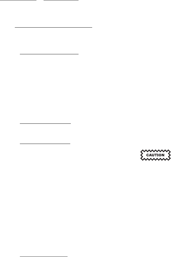
maintenance 523-0809018
4.2. MAINTENANCE SCHEDULE.
The TCAS function of the TSS-4100 does not require any periodic maintenance. However, the transponder function must have an
Air Traffic Control (ATC) transponder test and inspection according to FAR part 91 at a minimum of once every two years.
4.2.1. Cleaning and Painting.
NOTE
Observe all warnings and cautions listed in the advisories paragraph of this manual and the Collins Avionics Stan-
dard Shop Practices Manual.
This section presents the special instructions necessary for cleaning the traffic surveillance system equipment. For standard cleaning
instructions, the technician should follow the instructions outlined in the Collins Avionics Standard Shop Practices Manual, Collins
Part Number (CPN) 523-0768039.
4.2.2. Cleaning Indicators.
There are no indicators coming from any part of the Traffic Surveillance System to indicate necessary cleaning.
4.2.3. Cleaning Antennas.
Do not paint the antenna surface. Do not attempt to touch up the silk screening with paint.
Do not use cleaning solvents on the antennas.
NOTE
Refer to TRE-920 Service Information Letter 1-95, Radome Paint Peeling, for cleaning the TSA-4100 or TRE-930.
Methods of cleaning antennas follow.
a. Clean the exposed antenna surface using a soft cloth moistened with soap and water.
b. Rinse the surface with clean water and allow to air dry.
4.2.4. Approved Repairs.
No repairs should be attempted on any component of the traffic surveillance system while the equipment is installed in the aircraft.
4-2

maintenance 523-0809018
4.3. CONVERSION FROM TTR/TDR TO TSS SYSTEM.
The Traffic Surveillance System (TSS) is designed to take the place of one TDR-94D and a TTR-920, TTR-921, or TCAS-4000, in
an integrated system.
4.3.1. Preparation for Conversion.
A list of requirements follows:
• The TSS-4100 requires a 7.5 Amp breaker and 28 V input power.
• The TSS-4100 requires concentrated input busses. If the existing system has a TDR-94D strapped to Configuration 2, this is
already available. If the TDR-94D is strapped to any other configuration more changes will be necessary to the architecture of
the aircraft to accommodate the TSS-4100.
• The TSS-4100 requires radio altitude on the concentrated input bus for the TCAS function. This may require a change to the
input/output concentrator routing in order to route this data to the TSS-4100. This is already true for most Configuration 2 TDR-
94D installations.
• The TSS-4100 requires the following interfaces from the TDR it is replacing: Concentrated bus inputs, Control bus inputs, Con-
trol bus control discretes, All GPS inputs, X-side transponder standby input and output discretes, TDR No. 1 output bus (used
for TSS No. 1 output bus), and Air/Gnd input.
• The TSS-4100 requires the following interfaces from the TTR it is replacing: TA/RA output busses, RA Display and TA Display
input discretes, XT and TX busses to stand alone transponder, 600 output, (Climb Inhibit, Increase Climb Inhibit, Perf Limit,
and Advisory Inhibit) discrete inputs), and Visual Annunciation and Aural Annunciation output discretes.
• The TSS-4100 requires ARINC 615-3/4 data load capability. This is required to load aircraft configuration data.
• The TSS-4100 requires a couple of changes to the maintenance system. The maintenance labels being sent through the TSS No.
1 output bus are different. In addition there must be an option to show the TSS-4100 electronic nameplate.
• A change to the input/output concentrator tables to route the maintenance and electronic nameplate labels to the maintenance
system is necessary.
• The TSA-4100 replaces the TRE-920 directional antenna. The connectors for the TSA-4100 are rotated 45 degrees from the
placement of the connectors for the TRE-920. This is not an issue if there is only one hole in the skin of the aircraft for all of the
connectors to go through.
4.3.2. Differences between TTR/TDR and TSS.
Differences between the TTR/TDR and TSS systems follows:
• It is recommended that the TDR is on the left and the TSS-4100 is on the right. This is because a transponder is required to be on
the emergency battery bus. Typically, the left transponder is on this bus. A stand alone TDR uses less power than the TSS-4100.
• The TSS-4100 only supports A429 input busses. CSDB inputs, Gillham altitude, and analog inputs (for example, an analog radio
altitude input) are not supported.
• The TSS-4100 does not support an 8 audio output.
• The TSS-4100 supports a Time Mark input from both GPS sources. The TDR only supports an input from one GPS.
• Aircraft configuration data is maintained electronically in a file loaded through the TSS-4100 into an attached ECU. In a
TDR/TTR, this aircraft configuration data is maintained through hard straps on the back of the unit.
• The Mode S address for the TSS-4100 is maintained electronically within the attached ECU. TDR has 24 discrete inputs to set
theModeSAddress.
• The TSS-4100 requires cooling. It is highly recommended that the TSM is used as the fan. This mount can be monitored by the
TSS-4100.
NOTE
The TSS-4100 (hardware only) and TSSA-4100 (software only) are separate top level part numbers. Both must
be maintained as part numbers on the aircraft.
The TDR and TTR top level part numbers are different. Each includes both software, and hardware, components.
4-3

maintenance 523-0809018
4.4. DATA LOADING.
Explanations of data loading the ECU and the TSS-4100 follow.
4.4.1. ECU Data.
The External Compensation Unit (ECU) attached to the TSS-4100 holds two sets of data. The first set of data, the TSS ECU Media
Set Builder, contains the aircraft-configuration strapping for the TSS. These straps are detailed in Table 2-2. These data must be data
loaded through the TSS-4100. Refer to Table 4-1 for the data load busses and pins. The TSS-4100 will recognize the format of the
data set and store the data appropriately. The second set of data contains the aircraft Mode S Address. The TSS Mode S Address
Programming Tool loads just the Mode S address onto the ECU, refer to Paragraph 4.5 for details. Verification of a proper load of
these sets of data will be accomplished by reviewing the TSS-4100 Electronic Nameplate on the aircraft maintenance system. See
Paragraph 4.4.3 for more information on the TSS electronic nameplate.
Table 4-1. Data Load Buses And Pins
Bus Name Pin Numbers (Hi & Low) Bus Speed
Control B Input Bus LMP-7D & 7C Low
Dataload Input Bus LMP-7J & 7K High
TSS-1 Output Bus LMP-7A & 7B Low
TSS-2 Output Bus LMP-1A & 1B High
TSS-3 Output Bus RMP-1A & 1B High
4.4.1.1. If the bus speeds are configured differently in the ECU than what is listed in Table 4-1, follow the following steps in order
to load data.
a. Disconnect the cable from the ECU.
b. Power cycle the TSS-4100. This forces the TSS to use the default speeds listed in Table 4-1.
c. Reconnect the cable to the ECU.
d. Start the data load process as normal. The data load software always uses the default bus speeds. The bus speeds in the ECU
are ignored once the data load process has begun.
4.4.2. TSS Data Loading.
The TSSA-4100 and the ECU files are field loadable. Rockwell Collins has tested the TSS data load procedure using the ARINC
615-3 data loaders shown in Table 4-2. It is recommended that one of these data loaders, or an upgraded version of one of these data
loaders, is used to load the Traffic Surveillance System Application (TSSA) or the ECU.
4.4.2.1. The TSS may be data loaded using one of two input buses and one of three output buses. Loading must be done using the
default speed of the bus. Refer to Table 4-1 for bus names, pin numbers, and bus speeds. Refer to Table 4-2 for a list of the data
loaders that the TSS-4100 has been tested with. Most standard ARINC 615-3/4 compatible data loaders should be able to interface to
the TSS-4100. No special adaptor is called out for the TSS-4100. See the specifications of the applicable data loader for information
on the mating connector to be used.
4.4.2.2. The TSS-4100 needs one of the following sets of requirements in order to enter data load mode:
4-4

maintenance 523-0809018
• Set the SDI code of the unit to right or left.
• Make sure the airspeed and ground speed are each
less than 40 kts.
• Make sure the Data Load Enable discrete (RMP-
10K) is grounded.
• Make sure one of the air ground discretes is
grounded.
• Make sure the TSS-4100 receives an ARINC label
with a data load request. The TSS uses ARINC label
027 as the data load input label and sends label 226
as the data load output label.
OR • Set the SDI code of the unit is set to indeterminate
(neither of the SDI pins are grounded).
• Make sure the Data Load Enable discrete (RMP-
10K) is grounded.
• Make sure the Shop Mode Enable discrete (RMP-
6A) is grounded.
• Make sure the TSS-4100 receives an ARINC label
with a data load request.
4.4.2.3. Refer to Figure 4-1. To make sure that the TSSA has been loaded correctly, look at the electronic nameplate being sent
to the maintenance system. Refer to Paragraph 4.4.3 for data about the TSS electronic nameplate, and for what needs to be verified
after a TSSA or ECU media set data load.
Table 4-2. ARINC 615 Data Loaders.
Company Product Part Number
Honeywell (Allied
Signal)
PDL 964-0400-024
USB429win USB/ ARINC 429 Adapter 650-0200Avionica
USB429win 615 Data Loader SW for PC 700-0300; (version
040903)
Demo Systems PMAT-2000
Demo Systems PDL-615/MSD
4.4.3. TSS Electronic Nameplate.
Refer to Figure 4-1. Through the aircraft maintenance system it is necessary to access the TSS Electronic Nameplate. There are
three sections of the electronic nameplate.
4-5
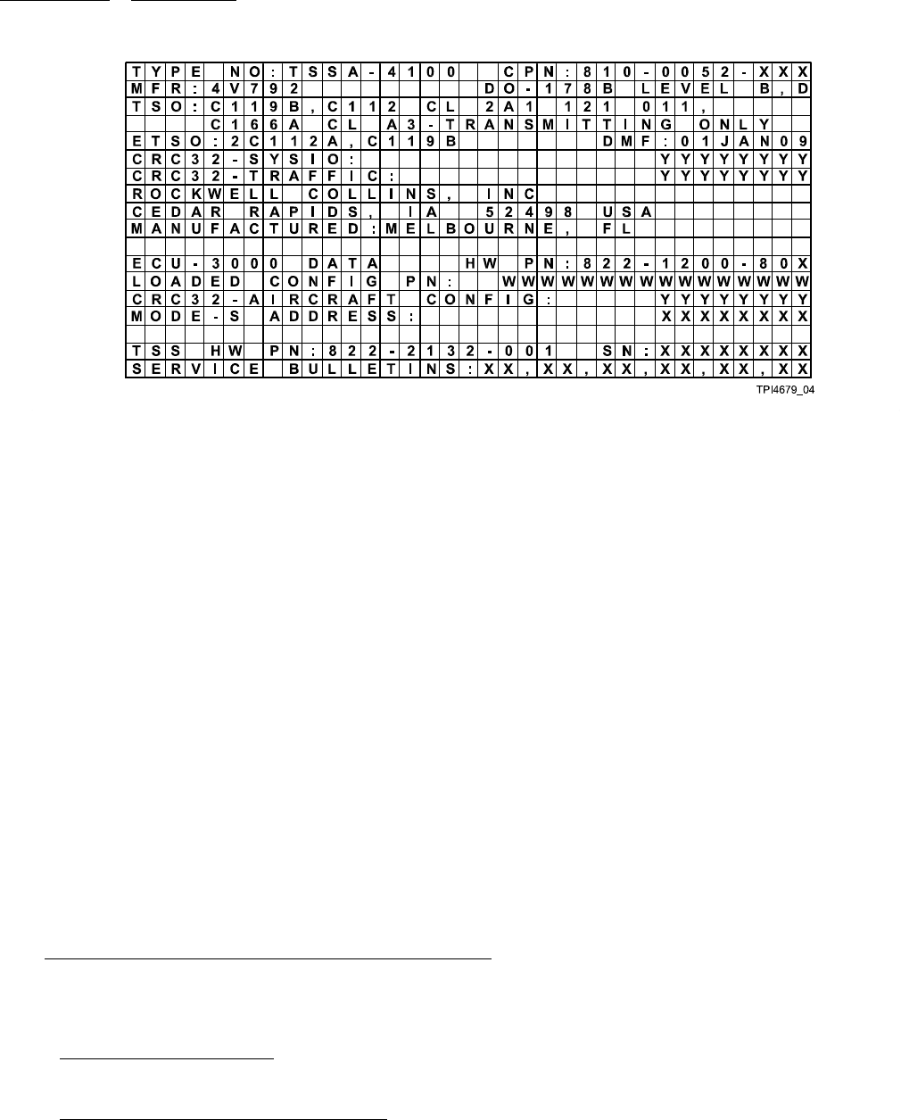
maintenance 523-0809018
Figure 4-1. TSS-4100, Electronic Nameplate
4.4.3.1. The top section of the electronic nameplate (lines 1 - 10) contains information regarding the TSSA-4100 software. When
the software is updated, make sure the items that follow:
• CPN – this is the top level software part number for the TSSA loaded
• CRC32-SysIO – this is a Cyclic Redundancy Check (CRC) on the first of two load sets that are part of the TSSA-4100
• CRC32-SysIO – this is a CRC on the second of two load sets that are part of the TSSA-4100.
4.4.3.2. The second section of the electronic nameplate (lines 12 - 15) contains data about the ECU connected to the TSS-4100.
4.4.3.2.1. When the ECU is properly connected to the TSS-4100, the hardware part number of the ECU is shown. If the ECU is
incorrectly formatted for the TSS or is not properly connected, the hardware part number will be shown as INVALID.
4.4.3.2.2. The second and third lines of the ECU portion of the electronic nameplate show the aircraft configuration that is loaded
into the ECU. If there is not an aircraft configuration loaded, or if the load is invalid, both the LOADED CONFIG PN and CRC32-
AIRCRAFT CONFIG line of the aircraft configuration are INVALID. When a valid aircraft configuration file is loaded into the ECU,
the part number and the CRC must be compared against the part number and CRC provided with the configuration file.
4.4.3.2.3. The last line of the ECU portion of the electronic nameplate shows the Mode S address stored within the ECU. The
Mode S address is shown in octal. Do not use this display of the Mode S address to verify a changed Mode S address. Instead, use
a transponder test set such as the IFR-6000 to verify a changed Mode S address.
4.4.3.3. The third section of the electronic nameplate (lines 17+) contains some information about the TSS-4100 hardware. This
is reported as a convenience only and is not to be used for official record keeping. The official part number, serial number, and list
of installed service bulletins are on the physical TSS-4100 nameplates.
4.5. TSS-4100 MODE S ADDRESS PROGRAMMING TOOL.
Rockwell Collins provides the TSS-4100 Mode S Address Programming Tool (Mode S tool). This tool changes the Mode S address,
and does not require data loading. The Mode S tool is provided to allow an update to the Mode S address of the TSS-4100 without
requiring a data load and without removing the TSS-4100 or the ECU from the aircraft.
4.5.1. Programming Tool Support.
Support for the TSS-4100 Mode S Programming Tool is provided by Rockwell Collins Product Support Representatives.
4.5.2. Programming Tool System Requirements.
The system requirements for using the TSS-4100 Mode S Address Programming Tool are as follows:
• A PC or laptop with Microsoft Windows™ XP or later
4-6

maintenance 523-0809018
• Be logged in with administrator credentials
• At least one RJ-45 port on the PC/laptop
• A Cross-Over RJ-45 Ethernet Cable.
4.5.3. Programming Tool Installation.
NOTE
This program requires Microsoft™ .NET 3.5 on the PC. If there is difficulty in installing .NET, uninstall all cur-
rently installed versions of Microsoft™ .NET before attempting the new installation. Contact your network ad-
ministrator or information technology department for further assistance.
Do the steps that follow to install the Mode S Programming Tool:
a. Obtain the TSS-4100 Mode S Address Programming Tool (CPN 811-2989-001).
NOTE
This is available through a CD-ROM. It may also be available through a digital download. Contact a Rockwell
Collins Product Support Representative for more information regarding this option.
b. Open the directory with the TSS-4100 Mode S Address Programming Tool setup files.
c. If .NET is not already installed, run Install .NET 3.5 Offline.exe. If unsure whether or not .NET is installed,
proceed to the next step. This setup program is provided by Microsoft™. This setup program will indicate that it is downloading
files from the internet, and will say, "Download Complete. You can now disconnect from the Internet." These statements are
normal. All necessary files are contained within the executable.
d. Run the Mode S Tool Installation Package.msi program. Follow the prompts to install the TSS-4100 Mode S
Address Programming Tool.
NOTE
If .NET is not installed, a prompt to download the applicable files from the Internet will show. It is recommended
to decline this download, and to perform Step 4.5.3.c. This is because the .NET framework is very large, and
downloading the files will take a significant amount of time.
4.5.4. Programming Tool Setup.
Make sure the IP address of the PC or laptop is within the proper address space. If the Mode S Programming Tool is expected to be
used often, then configure an IP port, on the PC or laptop, to not get an IP address from a DNS server at start-up.
NOTE
If there are problems setting up the IP address of the PC or laptop, contact your network administrator or informa-
tion technology department for assistance.
a. On the TSS-4100 Mode S Address Programming Tool, select the System > IP Addresses option.
b. Select the appropriate Network Interface Card (NIC). Refer to Figure 4-2.
NOTE
In the example below, the second NIC card is being selected.
4-7
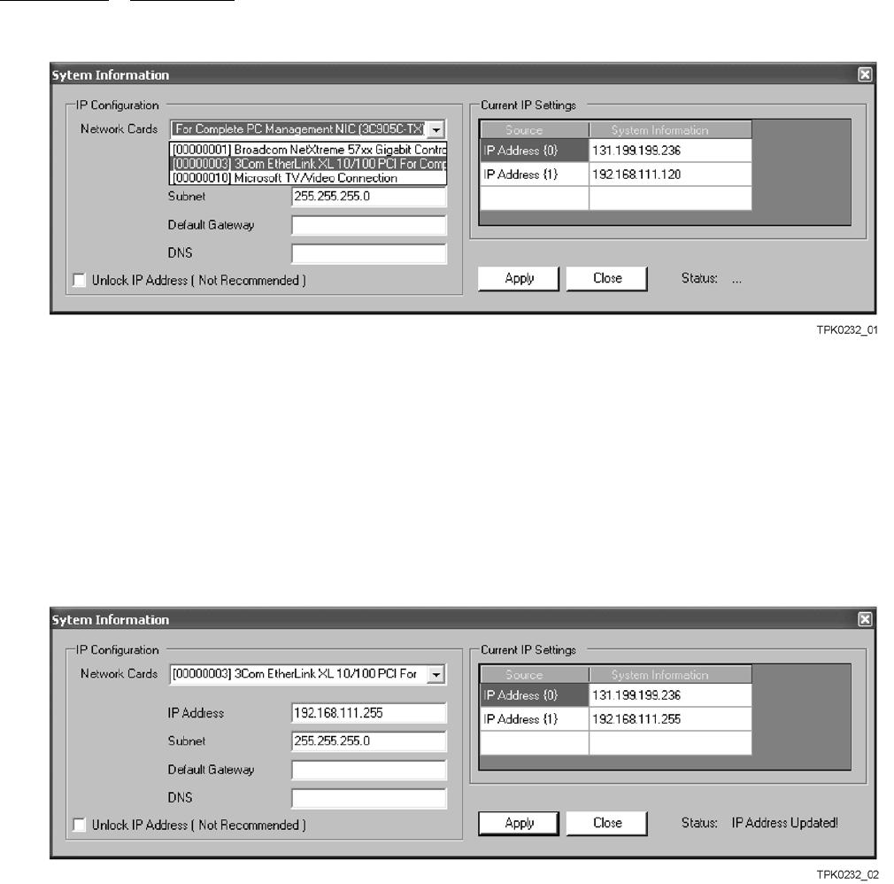
maintenance 523-0809018
Figure 4-2. Programming Tool - Select Network Interface Card
c. Refer to Figure 4-3. If necessary, change the IP address to be 192.168.111.XXX, where XXX is anything except 110. Change
the Subnet mask to 255.255.255.0. Make sure the Default Gateway and DNS server are blank.
NOTE
In the example below, the second IP address was changed from 192.168.111.120 to 192.168.111.255. This can be
seen by looking at the IP Address (1) field in the Current IP Settings window.
Also, the status now indicates IP Address Updated.
Figure 4-3. Programming Tool - Change the IP Address
d. Refer to Figure 4-4. If the IP address is locked by the program, it is possible to unlock the IP address and make changes. This
is not recommended, and if this is done it is recommended that these settings are changed back after use of the tool.
NOTE
In the example below, the first NIC card is selected, and there is a Default Gateway and DNS server. In order for
this NIC card to be used to communicate with the TSS-4100, these values would need to be cleared, and the IP
address would need to be set to the proper address space.
4-8
maintenance 523-0809018
Figure 4-4. Programming Tool - Unlock the IP Address
e. On the Programming Tool, select the System > Settings option. Make sure that the target IP address is 192.168.111.110
and that the port is 3000. Refer to Figure 4-5.
Figure 4-5. Programming Tool - Verify the IP Address
4.5.5. Programming Tool Instructions.
These instructions assume that the TSS-4100 is installed properly on the aircraft.
a. Make sure that the TSS-4100 is off and in the “On Ground” state.
Do not attempt to remove the front panel screws from the TSS-4100. This will likely result in either a sheared
screw or the screw not being able to be screwed back in. If this happens, please return the TSS-4100 to a Rockwell
Collins Service Center. These screws are designed to stay on the TSS-4100.
b. Loosen, but do not remove, the screws located on the front panel of the TSS-4100. Slide the access panel up and rotate it so
that the TSS-4100 RJ-45 maintenance ports are accessible.
c. Connect the cross-over cable from the PC to the TSS-4100 SYSP port.
NOTE
If a cross-over cable is not used, there will be no connection between the PC and the TSS-4100.
d. Turn the TSS-4100 on. Allow the unit up to 30 seconds to complete its power up sequence.
e. Run the TSS-4100 Mode S Address Programming Tool. If a default installation is done, the program may be accessed through
a shortcut on the desktop, or in the START menu under > Rockwell Collins > Mode S Programmer > TSS-4100 Mode S Tool.
f. Select the appropriate base for programming the Mode S address – either octal or hexadecimal.
4-9

maintenance 523-0809018
g. Enter the Mode S Address. If entering in octal, the entered is eight digits between 0 and 7. If entering in hexadecimal, the
entered value is 6 characters, each character being either a single digit (0 – 9), or a letter A thru F.
NOTE
If there are not enough characters for the selected base, zeroes (0s) will be added to the beginning of the value
entered.
h. Push the PROGRAM button and wait for up to a minute. The system will attempt to send the new Mode S address to the
TSS-4100. If the process completes incorrectly, an error message will appear in the Display Log. If the process completes
correctly, the TSS-4100 will reset itself. Allow the TSS-4100 to complete its power up sequence.
i. Push the QUERY button. Make sure that the Mode S address displayed is the newly programmed address.
NOTE
This is not an approved way to officially verify the current Mode S address setting.
j. Select the TSS-4100 as the active transponder. Make sure that there is no annunciation of a transponder failure. Interrogate the
TSS-4100 using a test set (such as the IFR-6000), and verify the Mode S Address.
k. Turn off the power to the TSS-4100.
l. Remove the cross-over cable from the TSS-4100.
m. Slide the cover back onto the front panel of the TSS-4100 and tighten the screws.
4.5.6. Programming Tool Overview.
Figure 4-6 shows a screen shot of the TSS-4100 Mode S Address Programming Tool. The description of the screen shot follows:
1. Octal / Hexadecimal: Radio buttons used to change between Octal and Hex just by clicking on the radio button with the
appropriate base for ease of readability. This affects both the input and the output.
2. Mode S Address: Text box in which to enter a Mode S address. If octal is selected, only the characters 0 – 7 are accepted.
If hexadecimal is selected, only the characters 0 – 9 and A – F are accepted.
3. Current Mode S: Text field that shows the Mode S address currently being used by the TSS-4100. This is only populated
after the Query button is pushed. This output is either in octal or in hexadecimal based on the current setting.
NOTE
The Current Mode S field is for informational use only. This is not an approved way to officially verify the
current Mode S Address setting. Checking the reported Mode S Address from the reply to an interrogation
of the TSS-4100 (using a test set such as the IFR-6000) is the appropriate way to verify the Mode S address.
4. Program Button: This button makes the programming tool attempt to program a new Mode S address into the TSS-4100.
5. Query Button: Button that causes the Programming Tool to obtain and display the Mode S address currently being used by
the TSS-4100. Pushing this button populates the Current Mode S text field. Pushing this button also causes a comparison
between the value in the Mode S address text field and the value in the Current Mode S text field.
6. Display Log: Log of communications between the TSS-4100 and the programming tool.
7. File: Three options are available under File: an option that replicates the functionality of the Program Button, an option that
replicates the functionality of the Query Button, and an option to exit the programming tool.
8. System: Two options are available under System: an option to view and change the target port and IP address, and an
option to view and change the IP address of the PC or laptop in use. These options are described in the Setup section of
these instructions.
4-10
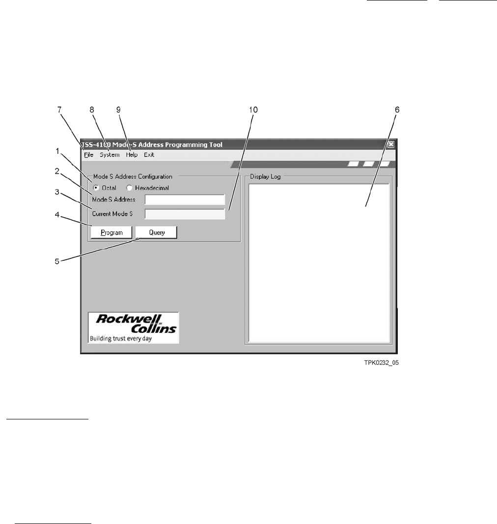
maintenance 523-0809018
9. Help: Two options are available under Help: an option to view programming tool version information and an option
to view these instructions.
10. Match Indicator: After pushing the Query Button, there will be an indication here if the address in the Mode S address box
matches the Current Mode S box. If they match it will be green; if they do not match it will be red.
Figure 4-6. Programming Tool - Screen Shot
4.6. LED INDICATORS.
This section contains descriptions of the Traffic Surveillance System (TSS) Light Emitting Diodes (LED) that show on the front
panel of the TSS-4100.
NOTE
Refer to the system pilot guide or the operation section of the system installation manual for displays indicators
and data.
4.6.1. LED Descriptions.
There are nine LED indicators on the front panel of the TSS-4100 to show the internal status and some external faults. Refer to
Figure 4-7. And, refer to Table 4-3 for a description of what each LED represents. The LED indicators show the results of the
power-up self-test and the results when the front panel TEST push button is pushed. The LED indicators also show the results of
any continuous monitoring errors detected during normal operation.
4-11
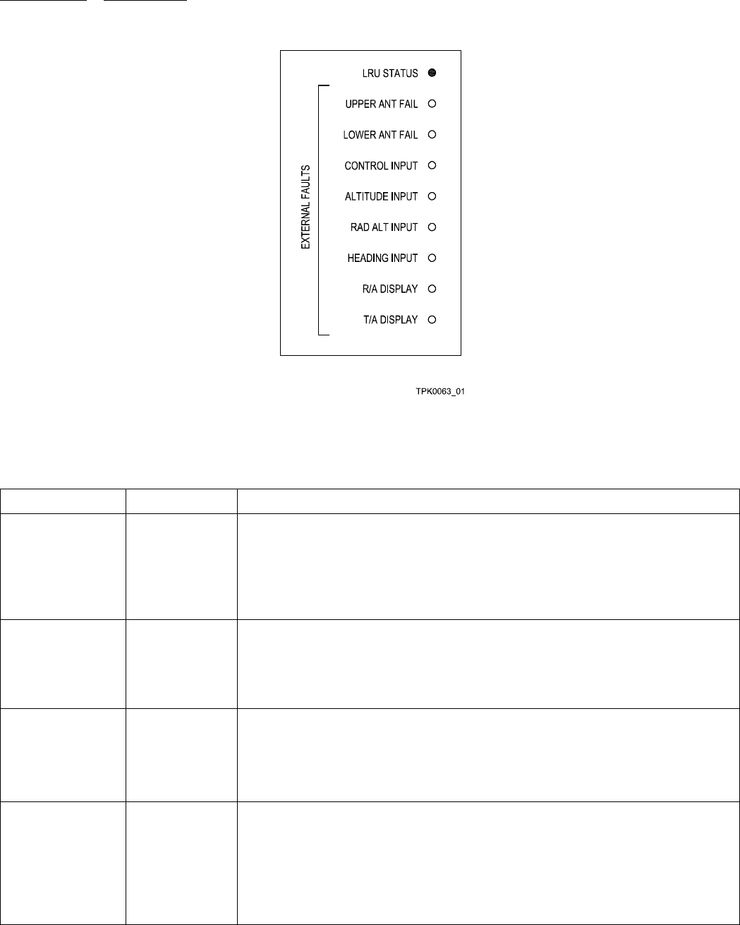
maintenance 523-0809018
Figure 4-7. TSS-4100 Front Panel LEDs
Table 4-3. LED Descriptions
Indicator Color Description
LRU STATUS indicator will light green whenever the self-test is successful. The LRU
STATUS indicator will light red whenever the self-test fails.
LRU STATUS RED/GREEN
If this is red, it is probable that the TSS will need to be replaced. See the maintenance
words for more information on this.
UPPER ANT FAIL indicator will light red whenever the impedance of the upper
antenna does not meet specification.
UPPER ANT FAIL RED
If this is lit the cabling from the TSS to the upper antenna needs to be checked.
LOWER ANT FAIL indicator will light red whenever the impedance of the lower
antenna does not meet specification.
LOWER ANT
FAIL
RED
If this is lit the cabling from the TSS to the lower antenna needs to be checked.
CONTROL INPUT indicator will light whenever a fault with the control panel is
detected.
CONTROL INPUT RED
If this is lit the connection between the TSS and the selected control panel needs to
be checked. Alternately, check the control panel selection discretes and verify they
are correctly being set.
4-12

maintenance 523-0809018
Table 4-3. LED Descriptions - Continued
Indicator Color Description
ALTITUDE FAULT indicator will light whenever the selected altitude source is
failed or missing.
ALTITUDE
INPUT
RED
If this is lit, check the transponder control panel to see if it is indicating that it is
sending a valid altitude. If the transponder control panel is not sending the altitude,
check to verify that the ADC on the PFD which is coupled to the autopilot is sending
valid information.
The RAD ALT INPUT indicator will light whenever the selected radio altitude inputs
are missing, or when there are two radio altitude inputs and they are not in agreement.
RAD ALT INPUT RED
If this is lit and there are two radio altimeters, try turning off one at a time to see if
the failure goes away. If the failure persists or if there is only one radio altimeter,
check the wiring from the radio altimeter.
The HEADING INPUT indicator will light whenever one of the following is missing:
selected heading, pitch angle, roll angle, or true heading.
HEADING INPUT RED
These are optional parameters for the TCAS function. If these parameters are not
available, the Traffic Surveillance System will work properly.
The R/A DISPLAY indicator will light whenever either R/A display discrete input is
not grounded.
R/A DISPLAY RED
If this is lit, check that both the left and right displays are active and can display TCAS
traffic. Push the TCAS test button, if the targets do not appear on one of the displays –
check the TA/RA port to that display. If the targets are shown on all displays, check
the RA discrete connection from the display to the TSS.
The T/A DISPLAY indicator will light whenever either T/A display discrete input is
not grounded.
T/A DISPLAY RED
This is a legacy TCAS discrete input and is not generally used any more. If this is
lit check to make sure that the straps setting the two T/A discrete inputs are correctly
strapped to ground.
4-13

maintenance 523-0809018
4.7. TEST EQUIPMENT AND POWER REQUIREMENTS.
Test equipment required to perform the post-installation test procedures is below. Other equipment may be entirely satisfactory if it
meets the specifications and is calibrated as necessary.
• Combined TCAS/Transponder test set (such as the IFR-6000), or a TCAS test set and a transponder test set
• Pitot Static Ramp Tester
• Radio Altimeter Ramp Tester.
4.7.1. Power Requirements.
All power required to perform the system tests and trouble shooting is provided by the aircraft in which the system is installed.
4-14

maintenance 523-0809018
4.8. TESTING AND TROUBLESHOOTING.
The procedures in this section help isolate LRU failures. The built-in tests present in the Traffic Surveillance System and in the
cross-side Mode S transponder system, make diagnostics easy to use on the flight line. For more information on the maintenance
reporting of the TSS-4100 and TDR-94D see Appendix B.
4.8.1. Pre-installation Testing.
To make sure that equipment works before installing the equipment in an aircraft, perform one of the tests that follow:
•Thefinal performance test
• The customer acceptance test
• Connect the unit to a system mock-up.
4.8.2. TCAS Self Test.
NOTE
Run this test as a Return to Service Test, and as part of the pilot pre-flight check.
The TCAS System Test shows that the Traffic Surveillance System is working properly. Run this test first whenever there is an
problem with the TCAS function. To initiate a TCAS self-test, perform the steps that follow:
a. Push the TEST button on the TCAS control, or push any other remote TCAS self-test button.
NOTE
The TSS will only go into test while on the ground.
b. Make sure that TEST is shown on the TrafficDisplay.
c. Make sure that the test intruder set of traffic symbols are as shown in Figure 4-8 and are as follows:
• An RA symbol (solid red square) at 2 nmi, at 200 feet relative altitude, above (+02), with no VS arrow, at a relative bearing
of +90 degrees.
• A TA symbol (solid yellow circle) at 2 nmi, at 200 feet relative altitude, below (–02), with ascending arrow, and a relative
bearing of –90 degrees.
• An PT symbol (solid cyan or white diamond) at 3.625 nmi, at 1000 feet relative altitude, below (–10), with descending
arrow, at a relative bearing of +33.75 degrees.
• An OT symbol (open cyan or white diamond) at 3.625 nmi, at 1000 feet relative altitude, above (+10), with no arrow, at a
relative bearing of –33.75 degrees.
4-15
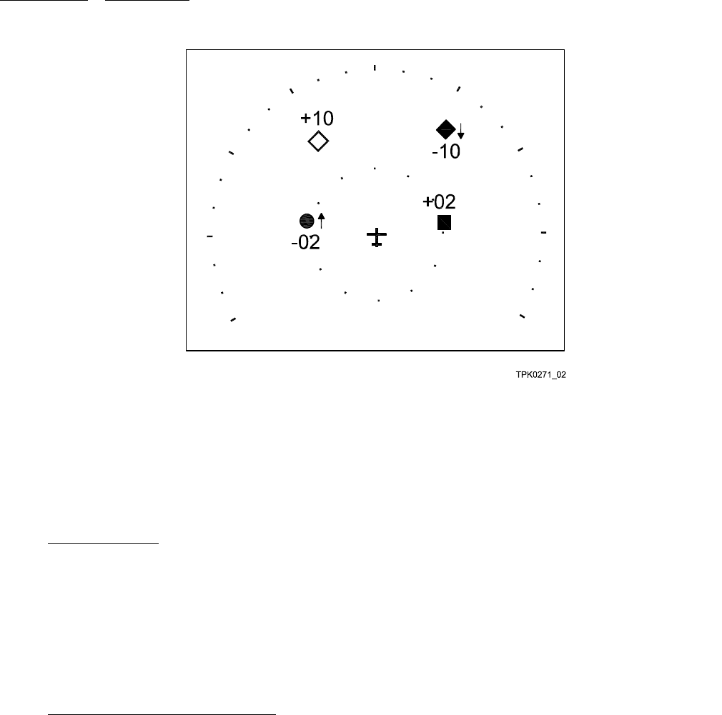
maintenance 523-0809018
Figure 4-8. TCAS Self Test Standard Output
d. Verify that RA vertical guidance is shown on the system. This may be done in the form of pitch cues, path cues, or on a vertical
speed tape.
e. After the test is completed, the audio system announces, "TCAS SYSTEM TEST OK." If the audio system announces, "TCAS
FAIL," instead, repeat self-test by pushing the TEST button on the front of the TSS-4100. The LEDs on the front of the unit
show the source of the failure. See section XXXX for a description of the meaning of the LEDs.
4.8.3. Equipment Setup.
Perform the steps that follow to setup the TCAS test equipment, only if a ramp-tester is used:
a. Position the TCAS test set according to the instructions supplied with the test set.
b. Make sure that the electrical power is applied to all of the aircraft systems that are required for Traffic Surveillance System
operation.
c. Turn off any Traffic Surveillance System ground operation controls that may be present in the installation under test. This
includes the WOW automatic-standby, and landing gear and flaps extended switching features.
d. Perform the test set self-test procedure to be sure the set is operating properly.
4.8.4. Radio Altitude System Failure Tests.
Perform this test when a pilot complaint suggests a problem related to the TCAS/Radio Altitude interface. A failure of all radio
altitude sources will fail the TCAS function. Do the steps that follow to perform a radio altitude system failure test:
a. Set the aircraft simulated altitude to 2,000 feet, both radio and barometric altimeters, and simulate WOW in air.
b. Select Traffic Advisory (TA)/RA or Automatic (AUTO) and verify that Traffic Surveillance System operation is normal.
c. Select the TSS-4100 as the active transponder.
d. Make sure no transponder failure annunciates.
e. Make sure that the single and dual radio altitude source operation is normal.
(1) If this is a single radio altimeter installation, simulate a radio altimeter system failure by opening the circuit breaker for
the radio altimeter. Make sure that TCAS FAIL is annunciated.
(2) Reset the circuit breaker opened in the previous step. Make sure that the Traffic Surveillance System returns to normal
operation.
4-16

maintenance 523-0809018
(3) If this is a dual radio altimeter installation, simulate a radio altimeter system failure by opening both of the radio altimeter
circuit breakers. Verify that TCAS FAIL is annunciated.
(4) Reset the circuit breaker for the No. 1 radio altimeter. Make sure that the Traffic Surveillance System returns to normal
operation.
(5) Open the circuit breaker for the No. 1 radio altimeter. Make sure that TCAS FAIL is annunciated.
(6) Reset the circuit breaker for the No. 2 radio altimeter. Make sure that the Traffic Surveillance System returns to normal
operation.
(7) Reset the circuit breaker for the No. 1 radio altimeter.
4.8.5. Pressure Altitude System Failure Tests.
Perform this test when there is pilot complaint suggesting a problem related to both the pressure altitude, and either the TCAS or the
transponder systems. A failure of the pressure altitude source makes the TCAS function fail. To perform a pressure altitude system
failure test, do the steps that follow:
a. If this is a single ADC installation, make sure that the source operation is normal.
(1) Select the left transponder. Select No. 1 or single altitude source.
(2) MakesurethattheTraffic Surveillance System operation is normal.
(3) Open the circuit breaker for the No. 1 altitude source. Make sure that the TCAS FAIL annunciates.
(4) Reset the circuit breaker for the No. 1 altitude source. Make sure that the Traffic Surveillance System returns to normal
operation.
(5) Select the right transponder and repeat this procedure.
b. If this is a multiple ADC installation, make sure that the source operation is normal.
(1) Make sure that all of the ADCs are on and are working. Make sure that the TSS-4100 is the selected transponder.
(2) Select the pilot PFD as the side that is driving the auto pilot (couple the auto pilot to the pilot side PFD). Have the pilot
side PFD use the No. 1 ADC. Make sure that the Traffic Surveillance System operation is normal.
(3) Open the circuit breaker for the ADC No. 1. Make sure that TCAS FAIL annunciates.
(4) If possible, select the ADC No. 2 on the pilot PFD. If this is not possible, then skip to Step 4.8.5.b.(6). Make sure that the
system returns to normal operation.
(5) Reset the circuit breaker for the No. 1 ADC and open the circuit breaker for the No. 2 ADC. Make sure that TCAS FAIL
annunciates.
(6) Reset the circuit breaker for the No. 2 ADC. If possible, select the No. 3 ADC on the pilot PFD. If this is not possible,
then skip to Step 4.8.5.b.(8). Make sure that the system returns to normal operation.
(7) Open the circuit breaker for the No. 3 ADC. Make sure that TCAS FAIL annunciates. Reset the circuit breaker for the
No. 3 ADC.
(8) Select the copilot PFD as the side driving the auto pilot (couple the auto pilot to the pilot PFD). Have the copilot PFD use
the No. 2 ADC. Make sure that the Traffic Surveillance System operates normally.
(9) Open the circuit breaker for the No. 2 ADC. Make sure that a TCAS FAIL is annunciated.
(10) If possible, select the No. 1 ADC on the copilot PFD. If this is not possible, then skip to Step 4.8.5.b.(12). Make sure that
the system returns to normal operation.
(11) Reset the circuit breaker for the No. 2 ADC and open the circuit breaker for the No. 1 ADC. Make sure that TCAS FAIL
annunciates.
(12) Reset the circuit breaker for the No. 1 ADC. If possible, select the No. 3 ADC on the pilot PFD. If this is not possible,
then skip to Step 4.8.5.b.(14). Make sure that the system returns to normal operation.
(13) Open the circuit breaker for the No. 3 ADC. Make sure that TCAS FAIL annunciates. Reset the circuit breaker for the
No. 3 ADC.
4-17

maintenance 523-0809018
(14) Reset the system so that each PFD is using its primary ADC source. Select the off side transponder as the active transpon-
der. Make sure that the system operates normally.
4.8.6. Range and Bearing Test.
Perform this test when there is pilot complaint suggesting a problem that is related to bearing accuracy. Run this test with an IFR-
6000 or other equivalent TCAS test set.
a. When testing the top antenna, monitor the TCAS display in the cockpit of the aircraft. Set the viewed range to 10 NM.
b. Set the Traffic Surveillance System aircraft simulated altitude below 400 ft agl. This automatically disables Mode C interroga-
tions (Mode S is still enabled) from the bottom antenna.
c. Set the test set parameters as follows:
(1) Altitude: Same as Traffic Surveillance System aircraft altitude
(2) Range: 8 nmi. Make sure a stationary PT symbol shows on the display. Make sure the PT symbol is at a relative bearing
that is equivalent to the bearing to the test set.
(3) VS: 0
(4) Rate: 0.
d. If a tarmac clock pattern (as shown in Figure 4-9) or a compass rose is available, use it as a reference to position the test set. If
not, position the TCAS test set at 45° intervals around the airplane and make sure that the displayed PT-symbol bearing agrees
with the bearing to the test set. Use two technicians if possible: one moves the test set around the aircraft, the other one watches
the display. The symbol moves about the aircraft symbol with no dropouts and no deviations in bearing that are more than 15
degrees. The center of the rose should be the TCAS antenna, not the center of the airplane. It is not required to test behind the
aircraft.
NOTE
Watch for large and constant bearing errors. An occasional bearing drift can be caused by signal reflections, and
is not an equipment failure. But if the symbol shifts to an adjacent or opposite quadrant, and remains there when
the test set moves into a test quadrant, then suspect a problem with the installation. Make sure this is a problem
by rotating the aircraft 90 degrees, then repeating the test. If the problem quadrant remains in the same position
relative to the aircraft, suspect an equipment failure (the TSS-4100, the TSA-4100, or the cabling). If the problem
quadrant stays fixed in space, suspect signal reflections or other outside interference.
4-18
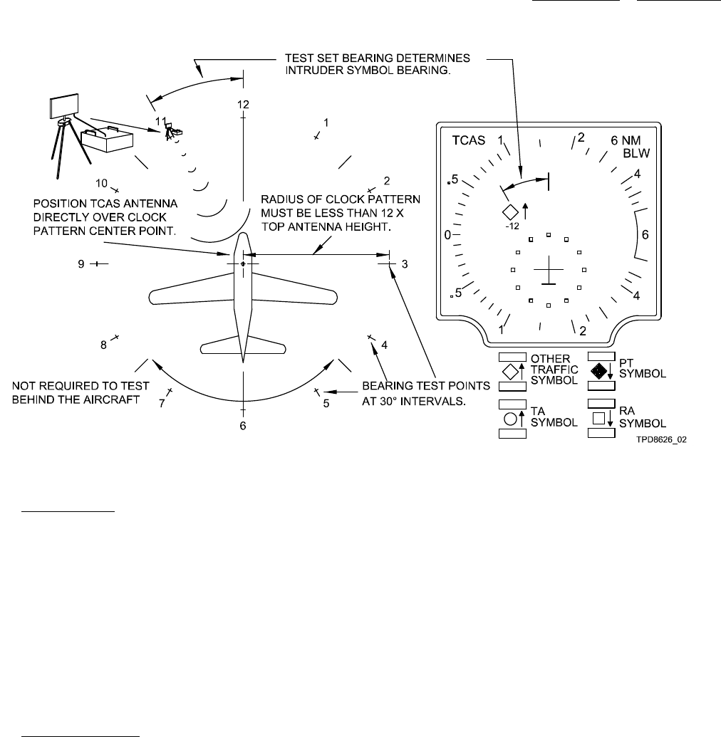
maintenance 523-0809018
Figure 4-9. Bearing Test, Aircraft and TCAS Test Set Orientation
4.8.7. TCAS RA Test.
Perform a TCAS RA test when there is pilot complaint suggesting a problem related to TAs or to RAs. Find out which approximate
bearing to check, if necessary. Run this test with an IFR-6000, or other equivalent TCAS test set.
a. Make sure that the pressure altitude and radio altitude is at or above 1500 ft.
b. Set the TCAS test set to make a collision course starting from 10 nmi away at 200 ft below the aircraft. Choose an appropriate
bearing from which this target should approach.
c. Make sure that initially on the TCAS display, an open cyan diamond is shown, then a filled-in cyan diamond is shown, then a
yellow circle is shown, then a red square is shown.
d. Make sure that when the yellow circle shows, a "Traffic, Traffic" aural is also heard.
e. Make sure that when the red square shows, that a "Climb, Climb" aural is also heard. Also make sure that a vertical advisory
shows on the Primary Flight Display (PFD). This indicates that a climb is commanded.
4.8.8. Transponder Tests.
Verify that the TSS transponder is functioning properly. This test should be performed whenever there is pilot complaint suggesting
a transponder issue. This may be run with an IFR-6000 or other equivalent transponder test set. It is recommended that all of the
transponder tests on the test set are run, but provided is a minimum subset that should be run.
NOTE
For a transponder to reply to Mode A, Mode C, or Mode S interrogations, it will be necessary to simulate the
aircraft being in the air. At a minimum this includes ensuring that the weight on wheels discrete is open and that
the radio altimeter reads above 50 feet. If possible it would be best to also simulate an airspeed of greater than
100 knots.
4-19

maintenance 523-0809018
a. Simulate a 2000 ft pressure altitude (uncorrected). Set the squawk code to 1234. Set the Flight ID to TEST1234. Set the
selected altitude to 16000 ft.
NOTE
Other altitude values can be used to run this test.
b. Run a Mode A/C decode and Side Lobe Suppression (SLS) test. Make sure they pass. Make sure that the proper altitude (2000
ft) and squawk code (1234) are reported.
c. Run an XPDR A/C Spacing Width Test, which also tests the ATCRBS all-call functionality. Make sure it passes.
d. Run the power and frequency tests. This also tests receiver sensitivity. Make sure they pass.
e. Run a Mode S All Call test. Make sure it passes. Make sure the Mode S address is correct.
f. Run a Mode S Reply test that includes a test of diversity. Make sure it passes.
g. Run a Mode S UF0 test. Make sure it passes. Make sure that the maximum airspeed range is what should be programmed for
that aircraft.
NOTE
The maximum airspeed range is programmed in the ECU as part of the aircraft configuration. If necessary, read
the documentation that comes with the aircraft configuration media set to see what this value should be.
h. Run a Mode S UF4 test. Make sure it passes. Make sure that the reported altitude is 2000 ft.
i. Run a Mode S UF5 test. Make sure it passes. Make sure that the reported squawk code is 1234.
j. Run a Mode S UF11 test. Make sure it passes.
k. Run Elementary Surveillance tests. Retrieve, at a minimum, registers 1,0, 1,7 and 2,0. Make sure that the tests pass and that
the retrieved value of register 2,0 is TEST1234.
l. Run Enhanced Surveillance tests. Retrieve, at a minimum, registers 4,0, 5,0, and 6,0. Make sure that the tests pass and that the
selected altitude reported in Register 4,0 is 16000 ft.
4.8.9. ADS-B Transmit Ground Test.
Run this test only if the ADS-B Out option is available. Perform this test when there is pilot complaint that there is an issue with the
ADS-B position transmissions from the aircraft.
NOTE
Flight testing, or GPS simulation of a flying aircraft, is required to do more testing than specified here.
a. Set the TSS-4100 as the selected transponder, and have it set to reporting altitude. Turn on the primary GPS and turn off any
secondary GPS. Allow the GPS to obtain a good position fix.
b. Use the IFR-6000, or any other ADS-B capable test set. Use it to monitor for Register 0.6, the surface position squitter. Make
sure that the decoded position is correct. Make sure that the position is synced to the time mark. On the IFR-6000, this is
indicated by the annunciation UTC. The indication that the position is not synced to the time mark is N/UTC.
c. If there is a secondary GPS, then turn off the primary GPS and turn on the secondary GPS. Let the secondary GPS to obtain a
good position fix.
d. Use the IFR-6000, or any other ADS-B capable test set, and use it to monitor for Register 0.6, the surface position squitter.
Make sure that the decoded position is correct. Make sure that the position is synced to the time mark.
4.8.10. Transponder/TCAS Suppression Bus Issues.
If the pilot report describes a Tracking Own Aircraft TCAS error when the non-TSS transponder is selected, then the transponder
suppression interface should be examined for open/short circuits. The suppression interface connects each TDR-94D connector,
TSS-4100 connector, and DME radio. When there is a suppression interface problem, the traffic display shows an intruder aircraft
4-20

maintenance 523-0809018
at zero-range, and at the same altitude (±200 ft) as own aircraft. The intruder stays at own altitude regardless of evasive vertical
maneuver. The problem can also make the display show a cluster of intruder targets at own altitude that move randomly. Check the
continuity of the suppression interfaces to show any short-circuits.
a. Remove all units connected to the suppression interface, including the TSS-4100, the transponder, and DME units.
b. Make sure that the continuity is less than 1to each contact in the interface. Make sure an open is greater than 100 kbetween
the center conductor and the shield/barrel of the coaxial connector.
c. Make sure that all coaxial pin contacts are positioned correctly.
d. When each unit is inserted back into the system but not powered, make sure that the connections to that unit are open.
4-21
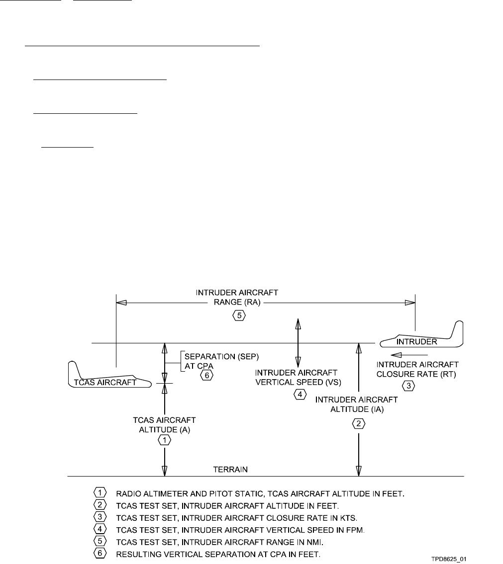
maintenance 523-0809018
4.9. INITIAL INSTALLATION CHECK OUT PROCEDURE.
Follow the procedures that follow to make sure the initial installation of the TSS-4100 performs well.
4.9.1. Initial Transponder Check Out.
Follow the procedures described in Paragraph 4.8.8.
4.9.2. Initial TCAS Check Out.
Follow the procedures that follow to make sure the initial installation of the TSS-4100 performs TCAS functions correctly.
4.9.2.1. Introduction.
NOTE
These tests simulate TCAS-equipped aircraft at different altitudes with altimeter test equipment, but simulate the
aircraft as stationary in space.
The instructions in this section use the TCAS test set to simulate certain flight scenarios. The activity of intruder aircraft is simulated
by the TCAS test set. That activity simulates the combined relative horizontal and vertical movements of both aircraft in an actual
flight situation. For example, in an actual flight situation in which a TCAS equipped aircraft and an intruder are approaching at
the same altitude both with a speed of 360 kts, the relative approach speed is 720 kts. This situation can be simulated by giving
the intruder a speed of 720 kts. Refer to Figure 4-10 for the parameters involved in the flight scenarios (CPA = Closest Point of
Approach).
Figure 4-10. Simplified Flight Scenario and Parameters
4.9.2.2. The altitude of the TCAS aircraft is simulated by means of radio and barometric altimeter system test equipment. The
TCAS test set allows entry of intruder-simulated altitude and vertical speed. A change in relative vertical speed can be simulated by
changing the intruder vertical speed while the test runs.
4-22

maintenance 523-0809018
4.9.2.3. You should be familiar with how to use the TCAS test set you are using. This procedure does not give detailed instructions
on test set operation. These are general instructions for a normal TCAS test set. Change these instructions to apply to your test set
if necessary.
4.9.2.4. Equipment Preparation.
NOTE
Equipment Preparation means running any necessary self-tests, making the necessary connections, and placing
the equipment as required for executing the test scenarios.
Follow the instructions supplied with the test equipment.
a. Prepare the TCAS test set, pitot-static ramp tester, and radio altimeter ramp tester for the tests that follow.
b. Prepare aircraft to simulate an in-flight condition. If necessary:
• Defeat the strut switch automatic standby feature.
• Apply electrical power.
c. Set the TCAS control to the STBY (standby) position.
d. If the TCAS system has an altitude volume selector switch (ABOVE-NORM-BELOW), then select NORM.
e. If the TCAS system has an altitude reference selector switch (REL-ABS), then select REL (relative).
f. Make sure the TCAS display shows no RA (resolution advisory), TA (Traffic Advisory), or PT (proximity traffic) symbols.
g. Make sure the TCAS display shows that the TCAS system is in standby mode.
h. Select TA/RA mode on the TCAS control.
NOTE
The TCAS controls may have a position labeled AUTO. If so, use AUTO instead of TA/RA.
i. Make sure the TCAS display shows that TCAS is no longer in standby.
j. Make sure the TCAS display is set for full-time traffic display. If it is not, then select traffic mode. Set the TCAS Display
Range to 15 nmi or greater.
NOTE
If airborne aircraft are near (i.e. within approximately 15 nmi), the display can show an other traffic(OT)orPT
symbol.
4.9.2.5. Test Scenarios. Refer to Figure 4-10 for the Test Scenario setups. If using the IFR-6000 Test Set, pre-program the unit
for the desired scenarios. This can save time on the flight line. In all test scenarios, the bearing to the intruder symbol on the TCAS
display will always be in the direction of the test set with respect to the airplane. That is, if the test set is situated off the right wing,
all intruder symbols will appear at or very near, the 3:00 o’clock position on the TCAS display. Here is a summary of the scenarios:
• Scenario 1a: Climb RA
• Scenario 1b: Descend RA
• Scenario 2a: Climb RA just below maximum climb altitude
• Scenario 2b: Descend RA just above the maximum climb altitude
• Scenario 3a: Increase Climb RA
• Scenario 3b: Increase Climb Inhibit (not applicable to all installations)
• Scenario 3c: Climb Inhibit (not applicable to all installations)
• Scenario 4a: Low Altitude Allow Increase Descent
4-23

maintenance 523-0809018
• Scenario 4b: Low Altitude Don't Allow Increase Descent
• Scenario 4c: Low Altitude TA Only.
NOTE
(1) There may be an approximately one second delay between symbol display and the aural advisory.
(2) The maximum climb altitude is documented at airplane certification and may be different than the airplane
service ceiling. Consult airplane data for applicable altitude. This altitude is programmed in the ECU.
4.9.2.5.1. Scenario 1a: Climb RA. In Scenario 1a, the intruder is placed below own airplane to induce a CLIMB RA command.
a. Set the airplane under test (UUT) simulated altitude to 12,000 ft and the radio altimeter to maximum setting.
b. Set the following values as necessary:
•TCASType:TCASII
• Intruder Type: Mode S
• Range at Start: 15.00 nmi
• Range Rate: +720 kts
• Altitude at Start: 11900 ft (if entering as an absolute altitude) or -100 ft (if entering relative altitude)
• Altitude Rate: 0.
c. Start the scenario.
d. Monitor the TCAS display and audio system for correct presentation as follows (NOTE 1):
Display Range (approx) Display Aural
12 nmi Other Traffic Symbol None
9 nmi TA Symbol TRAFFIC, TRAFFIC
6 nmi RA Symbol CLIMB, CLIMB
4.9.2.5.2. Scenario 1b: Descend RA. In Scenario 1b, the intruder is placed above own airplane to induce a DESCEND RA
command.
a. Set the airplane under test (UUT) simulated altitude to 12,000 ft and the radio altimeter to the maximum setting.
b. Set the following values as necessary.
•TCASType:TCASII
• Intruder Type: Mode S
• Range at Start: 15.00 nmi
• Range Rate: +720 kts
• Altitude at Start: 12,100 ft (if entering as an absolute altitude) or +100 ft (if entering relative altitude)
• Altitude Rate: 0.
c. Start the scenario.
d. Monitor the TCAS display and audio system for correct presentation as follows (NOTE 1):
4-24

maintenance 523-0809018
Display Range (approx) Display Aural
12 nmi Other Traffic Symbol None
9 nmi TA Symbol TRAFFIC, TRAFFIC
6 nmi RA Symbol CLIMB, CLIMB
4.9.2.5.3. Scenario 2a: Climb RA just below maximum climb altitude. Scenario 2a and 2b are tests intended to ensure that
the maximum climb altitude is properly programmed and read by TCAS.
a. Set airplane under test (UUT) simulated altitude to 50 ft below (+/- 10 ft) the maximum climb altitude (NOTE 2). Set the radio
altimeter to the maximum setting.
b. Set the following values as necessary:
• TCAS Type: TCAS II
• Intruder Type: Mode S
• Range at Start: 15.00 nmi
• Range Rate: +720 kts
• Altitude at Start: Set to 50 ft below the UUT altitude (or equal to 100 ft below the maximum climb altitude)
• Altitude Rate: 0.
c. Start the scenario.
d. Monitor the TCAS display and audio system for correct presentation as follows (NOTE 1):
Display Range (approx) Display Aural
If the maximum climb altitude is set between 10,000 and 20,000 ft:
12 nmi Other Traffic Symbol None
9 nmi TA Symbol TRAFFIC, TRAFFIC
6 nmi RA Symbol CLIMB, CLIMB
If the maximum climb altitude is set to 20,000 ft or more:
12 nmi Other Traffic Symbol None
9.6 nmi TA Symbol TRAFFIC, TRAFFIC
7 nmi RA Symbol CLIMB, CLIMB
4.9.2.5.4. Scenario 2b: Descend RA just above the maximum climb altitude. Scenario 2a and 2b are tests intended to
ensure that the maximum climb altitude is properly programmed and read by TCAS.
a. Set airplane under test (UUT) simulated altitude to 50 ft above (+/- 10 ft) the maximum climb altitude (NOTE 2). Set the radio
altimeter to the maximum setting.
b. Set the following values as necessary:
• TCAS Type: TCAS II
• Intruder Type: Mode S
• Range at Start: 15.00 nmi
• Range Rate: +720 kts
• Altitude at Start: Set to 50 ft below the UUT altitude (or equal to the maximum climb altitude)
• Altitude Rate: 0.
4-25

maintenance 523-0809018
c. Start the scenario.
d. Monitor the TCAS display and audio system for correct presentation as follows (NOTE 1):
Display Range (approx) Display Aural
If the maximum climb altitude is set between 10,000 and 20,000 ft:
12 nmi Other Traffic Symbol None
9 nmi TA Symbol TRAFFIC, TRAFFIC
6 nmi RA Symbol CLIMB, CLIMB
If the maximum climb altitude is set to 20,000 ft or more:
12 nmi Other Traffic Symbol None
9.6 nmi TA Symbol TRAFFIC, TRAFFIC
7 nmi RA Symbol CLIMB, CLIMB
4.9.2.5.5. Scenario 3a: Increase Climb RA. Scenario 3a can always be run.
a. Set airplane under test (UUT) simulated altitude to 11990 ft and set the radio altimeter to the maximum setting.
b. Set the following values as necessary.
•TCASType:TCASII
• Intruder Type: Mode S
• Range at Start: 15.00 nmi
• Range Rate: +720 kts
• Altitude at Start: 11,500 ft (if entering as an absolute altitude) or -490 ft (if entering relative altitude)
• Altitude Rate: 0.
c. Start the scenario.
d. Monitor the TCAS display and audio system for correct presentation as follows (NOTE 1):
Display Range (approx) Display Aural
12 nmi Other Traffic Symbol None
8 nmi TA Symbol TRAFFIC, TRAFFIC
6 nmi RA Symbol CLIMB, CLIMB
1.3 RA Symbol INCREASE CLIMB,
INCREASE CLIMB
4.9.2.5.6. Scenario 3b: Increase Climb Inhibit. Scenario 3b can only be run if the "Increase Climb Inhibit" discretes are
connected and can be stimulated. This test is intended to ensure TCAS properly recognizes the increase climb inhibit input (2500
ft/min climb inhibit). Follow the same steps as SCENARIO 3a except as follows:
a. Configure the airplane as needed to enable the 2500 ft/min climb inhibit condition. This may require a change to both the
altitude of the own aircraft and the altitude of the target aircraft. If the altitude of this test is greater than 20,000 ft, then the
ranges in the following step will be off. Also, the TA and the RA will occur sooner than indicated.
b. Monitor the TCAS display and audio system for correct presentation as follows (NOTE 1):
4-26

maintenance 523-0809018
Display Range (approx) Display Aural
12 nmi Other Traffic Symbol None
8 nmi TA Symbol TRAFFIC, TRAFFIC
6 nmi RA Symbol CLIMB, CLIMB
At a range < 6 nmi Verify that no increase climb advisory is issued. An RA should be
maintained, but which RA being issued can change. This test passes as
long as it is not an increase climb advisory.
4.9.2.5.7. Scenario 3c: Climb Inhibit. Scenario 3c can only be run if the "Climb Inhibit" discretes are connected and can be
stimulated. This test is intended to ensure TCAS properly recognizes the climb inhibit input (1500 ft/min climb inhibit). Follow the
same steps as SCENARIO 3a except as follows:
a. Configure the airplane as needed to enable the 1500 ft/min climb inhibit condition. This may require a change to both the
altitude of the own aircraft, and the altitude of the target aircraft. If the altitude of this test is greater than 20000 ft, the ranges
in the following step will be off. Also, the TA and the RA will occur sooner than indicated.
b. Monitor the TCAS display and audio system for correct presentation as follows (NOTE 1):
Display Range (approx) Display Aural
12 nmi Other Traffic Symbol None
8 nmi TA Symbol TRAFFIC, TRAFFIC
At a range < 8 nmi RA Symbol See Below
Verify no climb or increase climb advisory issued.
NOTE
An RA should be issued at about 6 nmi, and that it is possible that there is a change in which RA is being issued
inside of 6 nmi. This test passes as long as there is not a climb or an increase climb advisory.
4.9.2.5.8. Scenario 4a: Low Altitude Allow Increase Descent. Scenario 4a shows that a descend and increase descent advi-
sories will be given at low altitudes above a certain radio altimeter threshold.
a. Set airplane under test (UUT) simulated altitude to 1390 ft and set the radio altimeter to 1700 ft agl.
b. Set the following values as necessary.
• TCAS Type: TCAS II
• Intruder Type: Mode S
• Range at Start: 15.00 nmi
• Range Rate: +720 kts
• Altitude at Start: 1600 ft (if entering as an absolute altitude) or +210 ft (if entering relative altitude)
• Altitude Rate: 0.
c. Start the scenario.
d. At a range of 5 nmi set the altitude rate to -500 fpm. This altitude rate change must occur as close to 5 nmi as possible. The
timing of the alert is tight. Changing the value too soon or too late may cause other alerts to be annunciated.
e. Monitor the TCAS display and audio system for correct presentation as follows (NOTE 1):
4-27

maintenance 523-0809018
Display Range (approx) Display Aural
12 nmi Other Traffic Symbol None
5 nmi TA Symbol TRAFFIC, TRAFFIC
3 nmi RA Symbol DESCEND, DESCEND
At a range < 3 nmi RA Symbol INCREASE DESCENT,
INCREASE DESCENT
4.9.2.5.9. Scenario 4b: Low Altitude Don't Allow Increase Descent. Scenario 4b shows that within a certain radio altimeter
range, a descend advisory will be given, but an increase descent advisories will not be issued.
a. Set airplane under test (UUT) simulated altitude to 1390 ft and set the radio altimeter to 1400 ft agl.
b. Set the following values as necessary.
•TCASType:TCASII
• Intruder Type: Mode S
• Range at Start: 15.00 nmi
• Range Rate: +720 kts
• Altitude at Start: 1600 ft (if entering as an absolute altitude) or +210 ft (if entering relative altitude)
• Altitude Rate: 0.
c. Start the scenario.
d. At a range of 5 nmi set the altitude rate to -500 fpm. This altitude rate change must occur as close to 5 nmi as possible. The
timing of the alert is tight. Changing the value too soon or too late may cause other alerts to be annunciated.
e. Monitor the TCAS display and audio system for correct presentation as follows (NOTE 1):
Display Range (approx) Display Aural
12 nmi Other Traffic Symbol None
5 nmi TA Symbol TRAFFIC, TRAFFIC
3 nmi RA Symbol DESCEND, DESCEND
At a range < 3 nmi RA Symbol Make sure that there is no Increase
Descent RA, but that the RA continues.
4.9.2.5.10. Scenario 4c: Low Altitude TA Only. Scenario 4c shows that below a certain radio altimeter threshold, TCAS will
be in TA ONLY mode.
a. Set airplane under test (UUT) simulated altitude to 1390 ft and set the radio altimeter to 850 ft agl.
b. Set the following values as necessary.
•TCASType:TCASII
• Intruder Type: Mode S
• Range at Start: 15.00 nmi
• Range Rate: +720 kts
• Altitude at Start: 1600 ft (if entering as an absolute altitude) or +210 ft (if entering relative altitude)
• Altitude Rate: 0.
c. Verify that the TCAS display shows that TCAS is in TA ONLY mode.
4-28
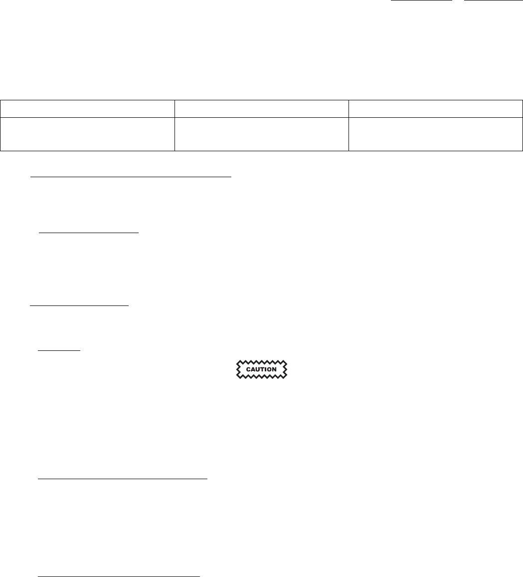
maintenance 523-0809018
d. Start the scenario.
e. At a range of 5 nmi (or less) set the altitude rate to -500 fpm. This altitude rate change should occur as close to 5 nmi as possible.
f. Monitor the TCAS display and audio system for correct presentation as follows (NOTE 1):
Display Range (approx) Display Aural
12 nmi Other Traffic Symbol None
4 nmi TA Symbol TRAFFIC, TRAFFIC
4.10. RETURN TO SERVICE TEST PROCEDURE.
Use the procedures that follow to make sure that the Traffic Surveillance System equipment that has been removed for maintenance,
repair, or bench testing and is now being reinstalled in an aircraft, operates normally. If the equipment fails these tests, use the fault
isolation procedures to determine which LRUs should be removed for shop maintenance.
4.10.1. Return to Service Test.
Perform the test steps that follow to return TSS equipment to service:
a. Perform the procedures in the TCAS self-test, described in Paragraph 4.8.2.
b. Perform the procedures in Transponder Tests, described in Paragraph 4.8.8.
4.11. INSPECTION/CHECK.
This section presents the unique instructions necessary to verify that the conditions of the Traffic Surveillance System are normal in
the airplane. Refer to the applicable component maintenance manual if any repair to the equipment is required.
4.11.1. Antennas.
Do not paint any antenna. Paint can affect the performance of the antenna.
Perform the items that follow:
• Make sure that the antenna is free of dents, cracks, punctures, and dirt.
• Make sure that the plugs are installed and sealed correctly.
4.11.2. TSS-4100 Traffic Surveillance System.
Perform the inspections that follow:
• Make sure that the transmitter/receiver and mount connectors are properly mated and that the transmitter/receiver is securely
fastened to the rack mounting position.
• Make sure that the knurled hold-down knobs on the rack are secured to the transmitter/receiver and are properly safety-wired.
• Make sure that the front RJ-45 access panel is properly fastened with both screws.
4.11.3. TDR-94D ATC/Mode S Transponder.
Perform the inspections that follow:
• Make sure that the transponder and mount connectors are properly mated and that the transponder is securely fastened to the rack
mounting position.
• Make sure that the knurled hold-down knobs on the rack are secured to the transponder and are properly safety-wired.
4-29/(4-30 Blank)

523-0809018
APPENDIX A
Faults and Warnings
A.1. GENERAL.
The faults and warnings generated by the TSS-4100 include Light Emitting Diodes (LED) and maintenance words. The LEDs show
on the front panel of the TSS-4100, and are described in Paragraph A.1. The maintenance words are sent by the TSS-4100 to the
Maintenance Diagnostic Computer, and are described in Appendix B.
A-1/(A-2 Blank)

523-0809018
APPENDIX B
Maintenance Words
B.1. MAINTENANCE DIAGNOSTIC WORDS.
Refer to Table B-1 for a list of the diagnostic words from the Traffic Surveillance System (TSS). Table B-2 shows how to interpret
a diagnostic word. Use this table to decode the hexadecimal readouts. Refer to Table B-3 for the hexadecimal-to-binary conversion
table. Refer to Table B-4 through Paragraph B.1.7 for a bit definition of each diagnostic word.
Table B-1. LRU Diagnostic Data, Reporting LRUs
Bus Label Number Label Name
TSS #1, #2, #3 Output Bus 350 TDR Maintenance Word
TSS #1, #2, #3 Output Bus 351 TSS-4100 Diagnostic Word 1
TSS #1, #2, #3 Output Bus 352 CDU Diagnostic Word 1
TSS #1, #2, #3 Output Bus 353 TSS-4100 Diagnostic Word 2
TSS #1, #2, #3 Output Bus 354 TSS-4100 Diagnostic Word 3
TSS #1, #2, #3 Output Bus 355 TSS-4100 Diagnostic Word 4
TA/RA #1, #2 Output Bus 350 ACAS Diagnostics
B-1

appendix B 523-0809018
Table B-2. Diagnostic Word Interpretation.
These words show on the ADVANCED DIAGNOSTICS pages.
SAMPLE 6-DIGIT HEXADECIMAL DISPLAY: 2 0 5 7 A E
BINARY VALUE BIT NUMBER HEX VALUE
19 0
210 1
411 1
812
E
1
113 0
214 1
415 0
816
A
1
117 1
218 1
419 1
820
7
0
121 1
222 0
423 1
824
5
0
125 0
226 0
427 0
828
0
0
129 0
230 1
Bits 10–12, 14, 16–19, 21, 23, and 30 are set.
431 0
832
2
0
B-2

appendix B 523-0809018
Table B-3. Hexadecimal to Binary Conversion Table.
HEXADECIMAL DIGIT
BINARY
VALUE 0 1234 5 6 7 8 9 A(10) B(11) C(12) D(13) E(14) F(15)
1 0 1010 1 0 1 0 1 0 1 0 1 0 1
2 0 0110 0 1 1 0 0 1 1 0 0 1 1
4 0 0001 1 1 1 0 0 0 0 1 1 1 1
8 0 0000 0 0 0 1 1 1 1 1 1 1 1
1. Turn to the table that shows the Line Replaceable Unit (LRU) diagnostic word to be decoded.
2. Convert each of the 6 hexadecimal digits shown on Multifunction Display (MFD) to a binary value.
3. Mark a 1 or a 0 by each bit number in the left column of the table.
4. The description of each line marked with a 1 is true.
B-3

appendix B 523-0809018
B.1.1. Label 350 TDR Maintenance Word.
This word is included as an output from the TSS as a way to be backward compatible with installations that previously had the TDR.
Many of the controllers use this label as a way to know if the selected transponder is failed. The only field of this word that should
be used is the SSM. If the SSM is 11, the TSS is not failed. If the SSM is 00, the TSS is failed. Refer to Paragraph B.2 for a complete
definition of this word. There has been no attempt to replicate TDR fault ID's by the TSS. This field will always be 0.
B.1.2. Label 351 TSS-4100 Diagnostic Word 1.
Refer to Table B-4 for the definition of this word and a possible solution to the indicated issue.
Table B-4. Label 351 TSS-4100 Diagnostic Word 1
Bit Label 351- TSS-4100 Diagnostics Word 1 Possible Solution
9SDI*
10 SDI*
11 TSS-4100 Unit Failure (Normal = 0 Fail = 1) Replace the unit
12 ACAS Function Summary (Normal = 0 Fail = 1) Replace the unit
13 XPDR Function Summary (Normal = 0 Fail = 1) Replace the unit
14 SysIO Function Summary (Normal = 0 Fail = 1) Replace the unit
15 ACAS System Summary (Normal = 0 Fail = 1) Check for other faults.
16 XPDR System Summary (Normal = 0 Fail = 1) Check for other faults.
17 ECU Unit Failure (Normal = 0 Fail = 1) Reprogram the ECU with the appropriate configuration
data. If this does not work replace the ECU.
18 Fan Unit Failure (Normal = 0 Fail = 1) Replace mount with integral fan
19 Upper Antenna Unit Failure (Normal = 0 Fail = 1) If no TSS unit failure, check wiring to the top antenna;
replace antenna if there is no wiring problem.
20 Lower Antenna Unit Failure (Normal = 0 Fail = 1) If no TSS unit failure, check wiring to the bottom antenna;
replace antenna if there is no wiring problem.
21 to 29 Pad
30 SSM**
31 SSM**
32 Odd Parity
*SDI Code: Bit 10 Bit 9 LRU Number **SSM Code: Bit 31 Bit 30 LRU Status
00NotUsed 00Normal
01Left 01NotUsed
10Right 10Test
1 1 Not Used 1 1 Not Used
B-4

appendix B 523-0809018
B.1.3. Label 352 CDU Diagnostic Word 1.
This label is forwarded if it is received through the selected control bus. The only change made to this label is changing the label
number from 350 (from the selected control bus) to 352. See the appropriate documentation for the attached controller if a definition
of this word is desired.
B.1.4. Label 353 TSS-4100 Diagnostic Word 2.
Refer to Table B-5 for the definition of this word.
Table B-5. Label 353 TSS-4100 Diagnostic Word 2
Bit Label 353- TSS-4100 Diagnostics Word 2 Note
9SDI*
10 SDI*
11 Pad
12 ACAS Function Fault (Normal = 0 Failed = 1) Indicated fault sets bit 12 in Label 351
13 XPDR Function Fault (Normal = 0 Failed = 1) Indicated fault sets bit 13 in Label 351
14 SysIO/ECU/Fan Function Fault (Normal = 0 Failed
=1)
Indicated fault sets bit 14, 17, or 18 in Label 351
15 ACAS System Fault (Normal = 0 Failed = 1) Indicated fault sets bit 15 in Label 351
16 XPDR System Fault (Normal = 0 Failed = 1) Indicated fault sets bit 16 in Label 351
28 to 17 12-bit Monitor IDRange 0 4095 Refer to Table B-4 for Monitor IDs
29 Start of Reporting Cycle (True = 1 False = 0)
30 SSM**
31 SSM**
32 Odd Parity
*SDI Code: Bit 10 Bit 9 LRU Number **SSM Code: Bit 31 Bit 30 LRU Status
00NotUsed 00Normal
01Left 01NotUsed
10Right 10Test
1 1 Not Used 1 1 Not Used
B.1.4.1. TSS-4100 Monitor IDs. Label 353 cycles through all active faults detected by the TSS-4100. If there is more than one
active fault, every 500 ms a different Monitor ID will be transmitted. The "Start of Reporting Cycle" bit is implemented so that it is
possible to know that all currently active faults are recorded. For example, if there are four active faults corresponding to Monitor
ID 2150, 2151, 2152, and 2153, then label 353 will output Monitor ID 2150 with the Start of Reporting Cycle bit set to 1. The other
Monitor IDs will be output one at a time with the "Start of Reporting Cycle" bit set to 0. Once all of the Monitor IDs have been
output, the TSS will start with Monitor ID 2150 again. Refer to Table B-6 for a list of all the possible Monitor IDs and the associated
faults.
B-5

appendix B 523-0809018
Table B-6. LRU Diagnostic Data, Fault Names and Categories.
Moni-
tor ID
Fault Name TSS-4100 Fault
Category
Monitor Name Internal /
External Fault
259 SysIO Failure SysIO Function SysIO PPC Program CRC Test Internal
260 SysIO Failuree SysIO Function SysIO Program RAM Monitor Internal
263 Module
Synchronization Fault
SysIO Function Traffic Synchronization Monitor Internal
264 SysIO Failure SysIO Function DSP Init Monitor Internal
265 SysIO Failure SysIO Function DSP Program CRC Test Internal
267 Dataload Inhibited
Request Fault Report
SysIO Function Dataload – Dataload Enable Monitor External
269 Dataload Inhibited
Request Fault Report
SysIO Function Dataload – Air Ground Monitor External
273 SysIO To TFC IMC
Transmit Fault
SysIO Function Intermodule Communication SysIO to
TFC Transmit Monitor
Internal
278 SysIO – TFC Comm
Fault
SysIO Function Traffic Receive Monitor Internal
279 SysIO Health Fault SysIO Function Internal Power Supply Monitor Internal
280 SysIO Health Fault SysIO Function Temperature Sensor Monitor Internal
281 SysIO Health Fault SysIO Function Boot Config ROM Monitor Internal
282 SysIO Health Fault SysIO Function NVRAM Monitor Internal
299 SysIO Load List
Check Fault
SysIO Function SysIO Load List Check Test Internal
303 TFC Load List Check
Fault
SysIO Function TFC OPS Load List Check Test Internal
304 SysIO Part Number
Comp Fault
SysIO Function SysIO Part Number Compatibility Test Internal
305 TrafficPartNumber
Comp Fault
SysIO Function Traffic Part Number Compatibility Test Internal
310 Test Inhibited Request
Fault Report
SysIO Function Initiated Test – Air Speed Monitor External
311 Test Inhibited Request
Fault Report
SysIO Function Initiated Test – Air Ground Monitor External
339 ECU Fault ECU Function ECU Data Fault Monitor External
340 Fan Fault Fan Function Fan Fault External
343 SysIO – TFC Comm
Fault
SysIO Function Traffic PTT Time-out Fault Internal
346 SysIO – TFC Comm
Fault
SysIO Function Traffic UIT Time-out Fault Internal
360 ACAS Aural File Fault ACAS Function ACAS Aural File Load List Check Test Internal
B-6

appendix B 523-0809018
Table B-6. LRU Diagnostic Data, Fault Names and Categories. - Continued
Moni-
tor ID
Fault Name TSS-4100 Fault
Category
Monitor Name Internal /
External Fault
361 ECU Fault ECU Function ECU Write Protection Fault Monitor External
362 ECU Fault ECU Function ECU Installation Part Number Fault Monitor External
363 SysIO Part Number
Comp Fault
SysIO Function Top Level Load Set Mismatch Monitor Internal
2048 Traffic Unit Failure ACAS & XPDR
Function
PPC Program Memory CRC Monitor Internal
2049 Traffic Input Failure XPDR System Mode S Discrete Address Continuous Monitor External
2050 Traffic Unit Failure ACAS & XPDR
Function
Mode S Discrete Address Continuous Monitor Internal
2053 Traffic Unit Failure ACAS & XPDR
Function
Radio Altitude Right Activity External
2069 Traffic Unit Failure ACAS & XPDR
Function
Receiver Monitor Internal
2071 Traffic Unit Failure ACAS & XPDR
Function
Receiver Frequency Lock Monitor Internal
2072 Traffic Unit Failure ACAS & XPDR
Function
Transmitter Frequency Lock Monitor Internal
2073 Traffic Unit Failure ACAS & XPDR
Function
Transmitter Power Monitor Internal
2074 Traffic Unit Failure ACAS & XPDR
Function
Transmitter Calibration Pulse Power Monitor Internal
2075 Traffic Unit Failure ACAS & XPDR
Function
Transmitter DAC Monitor Internal
2076 Traffic Unit Failure ACAS & XPDR
Function
Switch Card Monitor (Diode Monitor) Internal
2077 Traffic Unit Failure ACAS & XPDR
Function
Resolution Message Queue Full DSP-XPDR Mon Internal
2078 Traffic Unit Failure ACAS & XPDR
Function
Link DSP Initialization Monitor Internal
2079 Traffic Unit Failure ACAS & XPDR
Function
NVRAM Monitor Internal
2080 XPDR Input Failure XPDR System Mode S Discrete Address Monitor External
2083 Traffic Unit Failure ACAS & XPDR
Function
Hardware Init Status Monitor Internal
2084 Traffic Unit Failure ACAS & XPDR
Function
Watch Dog Timer Test Monitor Internal
2085 Traffic Unit Failure ACAS & XPDR
Function
Power Supply Monitors Internal
B-7

appendix B 523-0809018
Table B-6. LRU Diagnostic Data, Fault Names and Categories. - Continued
Moni-
tor ID
Fault Name TSS-4100 Fault
Category
Monitor Name Internal /
External Fault
2086 Traffic Unit Failure ACAS & XPDR
Function
IOSM - FPGA Initialization Monitor Internal
2087 Traffic Unit Failure ACAS & XPDR
Function
FPGA Health Status Monitor Internal
2088 Traffic Unit Failure ACAS & XPDR
Function
Transponder/ACAS Interface Monitor Internal
2089 Traffic Unit Failure ACAS & XPDR
Function
Mode S DSP Initialization Monitor Internal
2090 Traffic Unit Failure ACAS & XPDR
Function
Mode S DSP heart Beat Monitor Internal
2091 XPDR Input Failure XPDR System On Side GPS Time Mark Fault External
2092 Bottom Antenna
Connector Failure
ACAS & XPDR
Function
Bottom Antenna Connector Monitor External
2094 Top Antenna
Connector Failure
ACAS & XPDR
Function
Top Antenna Connector Monitor External
2096 Traffic Input Failure ACAS System Barometric Altitude Monitor External
2097 Barometric Altitude
Parametric Failure
ACAS System Barometric Altitude CRED Monitor External
2098 XPDR Input Failure XPDR System Cross Side GPS Time Mark Fault External
2100 ACAS Function Intruder Buffer Monitor Internal
2102 Receiver Calibration
Bottom Antenna
Failure
ACAS Function Receiver Calibration Bottom Antenna Monitor Internal
2103 Receiver Calibration
Top Antenna Failure
ACAS Function Receiver Calibration Top Antenna Monitor Internal
2104 ACAS Failure ACAS Function Resolution Message Queue Full XPDR-ACAS
Monitor
Internal
2105 Traffic Input Failure ACAS System Resolution Advisory (RA) Display 1 BITE External
2106 Traffic Input Failure ACAS System Resolution Advisory (RA) Display 2 BITE External
2107 Traffic Input Failure ACAS System RA Display 1 Status Discrete External
2108 Traffic Input Failure ACAS System RA Display 2 Status Discrete External
2109 Traffic Advisory (TA)
Display 1 Status
Discrete Failure
ACAS System Traffic Advisory (TA) Display 1 Status Discrete Internal
2110 Traffic Advisory (TA)
Display 2 Status
Discrete Failure
ACAS System Traffic Advisory (TA) Display 2 Status Discrete Internal
2112 XPDR Failure XPDR Function Acquisition Squitter Monitor Internal
B-8

appendix B 523-0809018
Table B-6. LRU Diagnostic Data, Fault Names and Categories. - Continued
Moni-
tor ID
Fault Name TSS-4100 Fault
Category
Monitor Name Internal /
External Fault
2113 ACAS / XPDR Control
Panel Validity Failure
ACAS & XPDR
System
Acquisition Squitter Monitor External
2114 ACAS / XPDR Control
Panel Validity Failure
ACAS & XPDR
System
ACAS Control Panel Validity Monitor External
2135 Traffic Unit Failure ACAS & XPDR
Function
ACAS 1Hz Producer IOSM Monitor Internal
2136 Traffic Unit Failure ACAS & XPDR
Function
XPDR 100 Hz Producer Monitor Internal
2138 Traffic Unit Failure ACAS & XPDR
Function
XPDR 10 Hz Producer IOSM Monitor Internal
2139 Traffic Unit Failure ACAS & XPDR
Function
CDTI 10 Hz Producer IOSM Monitor Internal
2140 Traffic Unit Failure ACAS & XPDR
Function
ADSB 10 Hz Producer Monitor Internal
2145 Traffic Unit Failure ACAS & XPDR
Function
CDTI to IOSM Display Data Monitor Internal
2146 Traffic Unit Failure ACAS & XPDR
Function
ACAS 1 Hz Producer CDTI Monitor Internal
2149 Traffic Unit Failure ACAS & XPDR
Function
Link DSP CRC Monitor Internal
B-9

appendix B 523-0809018
Table B-6. LRU Diagnostic Data, Fault Names and Categories. - Continued
Moni-
tor ID
Fault Name TSS-4100 Fault
Category
Monitor Name Internal /
External Fault
2150 Traffic Unit Failure ACAS & XPDR
Function
Link DSP CRC Monitor Internal
2151 Traffic Unit Failure ACAS & XPDR
Function
Mode S DSP CRC Monitor Internal
2152 Traffic Unit Failure ACAS & XPDR
Function
Configuration Monitor Internal
2157 Traffic Input Failure ACAS System Pitch Angle Input Monitor External
2158 Traffic Input Failure ACAS System Roll Angle Input Monitor External
2160 Traffic Input Failure ACAS System Mag Heading Input Monitor External
2168 Traffic Input Failure ACAS System Radio Altitude Left Activity External
2177 Traffic Unit Failure ACAS & XPDR
Function
ACAS Null Pointer Monitor Internal
2178 Radio Altitude
Parametric Failure
ACAS System Radio Altitude Parametric Failure External
2180 XPDR Failure XPDR Function Extended Squitter Monitor Internal
2190 Bottom Antenna
Failure
ACAS & XPDR
System
Bottom Forward Monitor External
2191 Bottom Antenna
Failure
ACAS & XPDR
System
Bottom Right Monitor External
2192 Bottom Antenna
Failure
ACAS & XPDR
System
Bottom Left Monitor External
2193 Bottom Antenna
Failure
ACAS & XPDR
System
Bottom Aft Monitor External
2194 Top Antenna Failure ACAS & XPDR
System
Top Forward Monitor External
2195 Top Antenna Failure ACAS & XPDR
System
Top Right Monitor External
2196 Top Antenna Failure ACAS & XPDR
System
Top Left Monitor External
2197 Top Antenna Failure ACAS & XPDR
System
Top Aft Monitor External
B-10

appendix B 523-0809018
B.1.5. Label 354 TSS-4100 Diagnostic Word 3.
Refer to Table B-7 for the definition of this word and a possible solution to the indicated issue.
Table B-7. Label 354 TSS-4100 Diagnostic Word 3
Bit Label 354- TSS-4100 Diagnostics Word 3 Possible Solution
9SDI*
10 SDI*
11 LMP - 1C/D (Control A) (Active = 0 Inactive = 1) Check wiring from appropriate controller to the TSS.
Repair wiring or replace the appropriate unit.
12 LMP - 6G/H (GPS #1) (Active = 0 Inactive = 1) (Optional connection) Check wiring from the onside GPS.
Repair wiring or replace the GPS.
13 LMP - 7C/D (Control B) (Active = 0 Inactive = 1) Check wiring from appropriate controller to the TSS.
Repair wiring or replace the appropriate unit.
14 LMP - 7E/F (ADS-B #1) (Active = 0 Inactive = 1)
15 LMP - 7G/H (ADS-B #2) (Active = 0 Inactive = 1)
16 LMP - 7J/K (Data Load) (Active = 0 Inactive = 1)
17 LMP - 8G/H (IAPS #1) (Active = 0 Inactive = 1) Check wiring from the onside I/O Concentrator. Repair
wiring or replace the concentrator.
18 LMP - 8J/K (CMU #1) (Active = 0 Inactive = 1)
19 RMP - 1C/D (Control C) (Active = 0 Inactive = 1) (Optional connection) Check wiring from appropriate
controller to the TSS. Repair wiring or replace the
appropriate unit.
20 RMP - 2G/H (GPS #2) (Active = 0 Inactive = 1) (Optional connection) Check wiring from the cross-side
GPS. Repair wiring or replace the GPS.
21 RMP - 7C/D (A768) (Active = 0 Inactive = 1)
22 RMP - 8G/H (IAPS #2) (Active = 0 Inactive = 1) Check wiring from the cross-side I/O Concentrator.
Repair wiring or replace the concentrator.
23 RMP - 8J/K (CMU #2) (Active = 0 Inactive = 1)
24 RMP - 8A/B (XT #2) (Active = 0 Inactive = 1) Check both the XT and TX bus wiring; check to see if off
side TDR is working properly.
25 to 29 Pad
30 SSM**
31 SSM**
32 Odd Parity
*SDI Code: Bit 10 Bit 9 LRU Number **SSM Code: Bit 31 Bit 30 LRU Status
00NotUsed 00Normal
01Left 01NotUsed
10Right 10Test
1 1 Not Used 1 1 Not Used
B-11

appendix B 523-0809018
B.1.6. Label 355 TSS-4100 Diagnostic Word 4.
Refer to Table B-8 for the definition of this word.
Table B-8. Label 355 TSS-4100 Diagnostic Word 4
Bit Label 355 −TSS Diagnostic Word 4
9SDI*
10 SDI*
14 to 11 Voltage Index (Range: 1 - 12)
1) Traffic reported 33VDC (LVDS message from Traffic)
2) Power Supply Side A 12 VDC (ADC Channel 12)
3) SysIO GAIN_REF (ADC Channel 10)
4) SysIO Top Temp (ADC Channel 15)
5) SysIO Bottom Temp (ADC Channel 14)
6) SysIO +8 VDC (ADC Channel 6)
7) SysIO - 8 VDC (ADC Channel 7)
8) SysIO Post Switch 12 VDC (ADC Channel 8)
9) SysIO 3.3 VDC (ADC Channel 4)
10) SysIO 1.5 VDC (ADC Channel 2)
11) SysIO DSP Core Voltage (ADC Channel 0)
12) SysIO RAM Voltage (ADC Channel 9)
15 Pad
16 Pad
28 to 17 12-bit Voltage Value (Range: 0 - 0xFFF)
NOTE
0xBAD means no voltage present to report (1011 1010 1101)
29 Pad
30 SSM**
31 SSM**
32 Odd Parity
*SDI Code: Bit 10 Bit 9 LRU Number **SSM Code: Bit 31 Bit 30 LRU Status
00NotUsed 00Normal
01Left 01NotUsed
10Right 10Test
1 1 Not Used 1 1 Not Used
B.1.6.1. TSS-4100 Label 355 Voltage Decode. Refer to Table B-7 to determine what the reading is and whether or not the
reading is within the specified range for the TSS-4100. In the Decode column,
V = (2.5 / 4096) X
where X is the raw decimal value encoded in bits 28 to 17.
B-12

appendix B 523-0809018
Table B-9. Label 355 Voltage Decode
Voltage Index Decode Nominal Upper Limit Lower Limit
1 (VDC) = V * 32.66 31.5 36.3 29.7
2 (VDC) = V * 11.01 12.0 12.60 11.40
3 (VDC) = V 1.5 1.575 1.425
4(°C)=(V0.424) *
160
Ambient temp N/A
5(°C)=(V0.424) *
160
Ambient temp N/A
6 (VDC) = V * 5.71 8.0 8.22 7.54
7 (VDC) = V * -4.21 -8.0 -7.24 -8.34
8 (VDC) = V * 10.53 12.0 12.60 11.40
9 (VDC) = V * 2.00 3.3 3.44 3.16
10 (VDC) = V 1.5 1.57 1.43
11 (VDC) = V 1.26 1.32 1.20
12 (VDC) = V 1.25 1.35 1.15
B-13

appendix B 523-0809018
B.1.7. Label 350 ACAS Diagnostics.
Refer to Table B-10 for the definition of this word and a possible solution to the indicated issue. This label is created to replicate an
equivalent word from Rockwell Collins TTR series of TCAS units. This is not sent through the TSS #X output busses. This label
should only be used as a supplement to Label 351 and Label 354 on the TSS #X output busses.
NOTE
This label is sent to the displays on the TA/RA busses.
Table B-10. Label 350 ACAS Diagnostics Word
Bit Label 350 −ACAS Diagnostics Possible Solution
9Pad
10 Pad
11 TSS ACAS Fail (Normal = 0 Failure = 1) Check for other faults.
12 Upper Antenna (Normal = 0 Failure = 1) Check wiring to the top antenna; replace antenna if there
is no wiring problem or a TSS unit fault.
13 Lower Antenna (Normal = 0 Failure = 1) Check wiring to the bottom antenna; replace antenna if
there is no wiring problem or a TSS unit fault.
14 Radio Altimeter Input Bus #1 (Normal = 0 Inactive
=1)
Check the units and the wiring path from radio altimeter
#1 to the I/O Concentrator to the TSS.
15 Radio Altimeter Input Bus #2 (Normal = 0 Inactive
=1)
Check the units and the wiring path from radio altimeter
#2 to the I/O Concentrator to the TSS.
16 TSS Transponder (Active or Stby = 0 Fail = 1) Check for other faults.
17 X-Side Transponder (Active or Stby = 0 Fail = 1) Check wiring to the Cross side TDR; replace TDR if
necessary.
18 Attitude Input Bus (Normal = 0 Inactive = 1) Check the units and the wiring path from the selected
AHRS/IRS to the I/O Concentrator to the TSS.
19 Magnetic Heading Input Bus (Normal = 0 Inactive
=1)
Check the units and the wiring path from the selected
AHRS/IRS to the I/O Concentrator to the TSS.
20 TCAS System Status (Normal = 0 Failure = 1) Check for other faults.
21 Pad
22 Pad
23 TA 1 Display System Status (Normal = 0 Failure = 1) Check the ground strap to the TA #1 discrete.
24 TA 2 Display System Status (Normal = 0 Failure = 1) Check the ground strap to the TA #2 discrete.
25 RA 1 Display System Status (Normal = 0 Failure = 1) Check the discrete wire from the displays to the TSS;
check the RA/TA bus to the appropriate displays. If
the wiring is OK AND there is no TSS unit fault, then
Replace Display.
26 RA 2 Display System Status (Normal = 0 Failure = 1) Check the discrete wire from the displays to the TSS;
check the RA/TA bus to the appropriate displays. If
the wiring is OK AND there is no TSS unit fault, then
Replace Display.
B-14

appendix B 523-0809018
Table B-10. Label 350 ACAS Diagnostics Word - Continued
Bit Label 350 −ACAS Diagnostics Possible Solution
27 Not Used
28 Not Used
29 Not Used
30 SSM*
31 SSM*
32 Odd Parity
*SSM Code: Bit 31 Bit 30 LRU Status
00Normal
01NotUsed
10Test
11NotUsed
B-15

appendix B 523-0809018
B.2. TDR-94D DIAGNOSTIC CODES.
Refer to Table B-11. A traffic control unit such as the CTL-92(), or a maintenance diagnostic system, lists TDR-94D diagnostic
codes.
Table B-11. TDR-94D Diagnostic Codes.
DIAGNOSTIC DISPLAY
PRIMARY
CODE
SECONDARY
CODE DESCRIPTION T1 F/W
None
(refer to Note)
No Fault Found
NOTE
With a No Fault Found condition, a pulsating AL will appear in the upper window and the baro altitude
will appear in the lower window.
10 Power Supply Diagnostics (Note 1) (Note 1)
11 +5-V dc Yes Yes
12 + 70-V dc No No
13 +35-V dc No No
14 LVPS No No
20 Transmitter / Modulator diagnostics (Note 2) (Note 2)
21 Final stage over current Yes Yes
22 Top antenna low-power output No No
23 Bottom antenna low-power output No No
24 Transmitter over temperature No No
30 Synthesizer diagnostics No No
31 Synthesizer lock detect No No
32 Synthesizer low-power detect No No
40 Receiver / IF diagnostics No No
41 Top receiver channel No No
42 Bottom receiver channel No No
43 Top Differential Phase Shift Keying (DPSK)
demodulator
No No
44 Bottom DPSK demodulator No No
50 Program memory (ROM) diagnostics Yes Yes
51 High-byte ROM Yes Yes
52 Low-byte ROM Yes Yes
53 Both ROM chips Yes Yes
60 Volatile memory (RAM) diagnostics Yes Yes
61 High-byte RAM Yes Yes
B-16

appendix B 523-0809018
Table B-11. TDR-94D Diagnostic Codes. - Continued
DIAGNOSTIC DISPLAY
PRIMARY
CODE
SECONDARY
CODE DESCRIPTION T1 F/W
62 Low-byte RAM Yes Yes
63 Both RAM chips Yes Yes
64 Cache RAM Yes Yes
65 Cache RAM and high-byte RAM Yes Yes
66 Cache RAM and low-byte RAM Yes Yes
67 Cache RAM and both RAM chips Yes Yes
68 Dual Port RAM Yes Yes
70 Non-Volatile RAM (NVRAM) diagnostics No No
80 Serial input control bus diagnostics (Note 4) No
81 ARINC 429 control UART (Note 4) No
82 ARINC 429 control Port A inactive (Note 4) No
83 ARINC 429 control Port B inactive (Note 4) No
84 ARINC 429 control Port C inactive (Note 4) No
85 CSDB control input Port A inactive (Note 4) No
87
(-004 TDR-94D only)
AIS/Air Data System (ADS) UART failure No No
88
(-004 TDR-94D only)
GPS UART failure No No
89
(-004 TDR-94D only)
IRS UART failure No No
90 Serial altitude input diagnostics No No
91 ARINC 429/575 altitude UART No No
92 ARINC 429/575 input Port A inactive No No
93 ARINC 429/575 input Port B inactive No No
94 CSDB altitude input Port A inactive No No
95 CSDB altitude input Port B inactive No No
99 No data received — —
A0 ADLP communication diagnostics No No
A1 ADLP com A/B UART No No
A2 ADLP com A/B bus inactive No No
A3 ADLP com C/D UART No No
A4 ADLP com C/D bus inactive No No
B0 TCAS communication diagnostics No No
B1 TCAS UART No No
B-17

appendix B 523-0809018
Table B-11. TDR-94D Diagnostic Codes. - Continued
DIAGNOSTIC DISPLAY
PRIMARY
CODE
SECONDARY
CODE DESCRIPTION T1 F/W
B2 TCAS unit — —
B3 TCAS bus inactive No No
B4 TCAS protocol error No No
C0 Squitter diagnostics No Yes
C1
(TDR-94D only)
Top channel squitter No Yes
C2
(TDR-94D only)
Bottom channel squitter No Yes
D0 (TDR-94D only) Diversity diagnostic No Yes
E0 Message processor diagnostics No No
E1
(TDR-94D only)
Top channel message processor, soft failure No No
E2 Bottom channel message processor, soft failure No No
E3 Top channel message processor, hard failure Yes Yes
E4 Bottom channel message processor, hard failure Yes Yes
F0 Configuration diagnostics No No
F1 Mode S discrete address changed No No
F2 TCAS selection changed No No
F3 Altitude units selection changed No No
F4 Max airspeed program selects changed No No
F5 Port selects changed No No
F6 SDI selects changed No No
F7 Single antenna selection changed No No
F8 ADLP selection changed No No
F9-FE Not assigned No No
B-18

appendix B 523-0809018
Table B-11. TDR-94D Diagnostic Codes. - Continued
DIAGNOSTIC DISPLAY
PRIMARY
CODE
SECONDARY
CODE DESCRIPTION T1 F/W
FF Unacceptable Mode S address selected (all address
lines identical)
Yes Yes
NOTE
1. Transmitter is inhibited (TI) and failure warn (F/W1) output (P1-31) is set only if a diagnostic Code 11 is detected.
2. Transmitter is inhibited and F/W1 discrete is set only if a diagnostic Code 21 is detected.
3. Transmitter is inhibited and TDR-94/TDR-94D is set to standby only if all selected control inputs are nonfunctional.
4. Transmitter is inhibited and TDR-94/TDR-94D is set to standby only if the control bus failure is detected on the selected
control bus.
5. Transmitter is inhibited and TDR-94/TDR-94D is set to standby only if serial control is selected and all serial inputs are
nonfunctional.
6. Except for 00, 70, and D0, primary diagnostics are not displayed.
7. F/W SET refers to:
• TDR-94D fault monitor discrete output, P1-31, set to high level
• TDR-94D CSDB data word Label 1F, Byte-1, Bit-7, set to logic 0
• TDR-94D ARINC 429 SSM and other data bits related to diagnostics set to the appropriate fault level.
B-19/(B-20 Blank)

523-0809018
APPENDIX C
Buses and Other Interfaces
C.1. INTERFACE TYPES.
The various Line Replaceable Unit (LRU) in the Traffic Surveillance System (TSS) interface with each other and other systems
using primarily ARINC 429 or discrete interfaces. Each bus has a unique name. The buses are primarily ARINC 429 or discrete
format. Refer to Table C-1 for a list of the possible discrete and ARINC bus names. Refer to Table C-2 through Table C-16 for lists
of the word labels on each digital bus. Interfaces to the ECU, audio systems, and test equipment are not described here.
Table C-1. Buses and Discretes
Name of Bus or Discrete Type of Bus or Discrete
TSS Active (to XTDR) Discrete Output
Visual Annun C Discrete Output
Visual Annun P Discrete Output
Visual Annun TA Discrete Output
Fan Off (100ma) Discrete Output
Aural Advisory C Discrete Output
Aural Advisory P Discrete Output
Aural Advisory TA Discrete Output
XTDR Active (from XTDR) Discrete Input
Extended Squitter Disable Discrete Input
Perf Limit Discrete Input
Simulator Enable Discrete Input
Air/Gnd(F) #1 Discrete Input
Fan Monitor Discrete Input
Air/Gnd(F) #2 Discrete Input
Climb Inhibit #1 Discrete Input
Climb Inhibit #2 Discrete Input
Climb Inhibit #3 Discrete Input
Climb Inhibit #4 Discrete Input
Increase Climb Inh #1 Discrete Input
Increase Climb Inh #2 Discrete Input
Increase Climb Inh #3 Discrete Input
Increase Climb Inh #4 Discrete Input
Advisory Inhibit #1 Discrete Input
Advisory Inhibit #2 Discrete Input
C-1

appendix C 523-0809018
Table C-1. Buses and Discretes - Continued
Name of Bus or Discrete Type of Bus or Discrete
Advisory Inhibit #3 Discrete Input
Advisory Inhibit #4 Discrete Input
TA Display Valid #1 Discrete Input
TA Display Valid #2 Discrete Input
RA Display Valid #1 Discrete Input
RA Display Valid #2 Discrete Input
Burst Tune Select Discrete Input
Control Port Select 0 Discrete Input
Control Port Select 1 Discrete Input
Advisory Annun Cancel Discrete Input
Data Load Enable Discrete Input
SDI Position 1 Discrete Input
SDI Position 2 Discrete Input
TSS-1 Output Bus
TSS-2 Output Bus
TSS-3 (Data Load) Output Bus
TA/RA-1 Output Bus
TA/RA-2 Output Bus
TX2 (TSS to TDR) (or ADLP) Output Bus
ADS-B #1 (Provision) Output Bus
CMU (Provision) Output Bus
General Purpose #1 (Provision) Output Bus
Control A Input Bus
Control B Input Bus
Control C Input Bus
IAPS #1 Input Bus
IAPS #2 Input Bus
GPS #1 Input Bus
GPS #2 Input Bus
XT2 (TDR to TSS) (or ADLP) Input Bus
Data Load Input Bus
CMU #1 (Provision) Input Bus
CMU #2 (Provision) Input Bus
ADS-B #1 (Provision) Input Bus
C-2

appendix C 523-0809018
Table C-1. Buses and Discretes - Continued
Name of Bus or Discrete Type of Bus or Discrete
ADS-B #2 (Provision) Input Bus
A768 Future (Provision) Input Bus
C-3

appendix C 523-0809018
C.2. TSS DISCRETE OUTPUTS.
Refer to Table C-2 for a list of the discrete outputs for the TSS and their expected destinations.
Table C-2. TSS Discrete Outputs
Pin Name Conn Pin Expected Connection/Notes
TSS Active (to XTDR) LMP 2E Cross side transponder, even if it is another TSS
Visual Annun C LMP 3A Not normally connected
Visual Annun P LMP 3B Not normally connected
Visual Annun TA LMP 3C Not normally connected
Fan Off (100ma) LMP 3D Connect to TSM to control the fan
Aural Advisory C LMP 4A May be connected as a push-to-talk for audio outputs
Aural Advisory P LMP 4B May be connected as a push-to-talk for audio outputs
Aural Advisory TA LMP 4C May be connected as a push-to-talk for audio outputs
C-4

appendix C 523-0809018
C.3. TSS DISCRETE INPUTS.
Refer to Table C-3 for a list of the discrete inputs to the TSS and their expected connections.
Table C-3. TSS Discrete Inputs
Pin Name Conn Pin Expected Connection/Notes
XTDR Active (from XTDR) LMP 2J Cross side transponder
Extended Squitter Disable LMP 2K This will only be connected if there is a switch to turn off
extended squitters
Perf Limit LMP 3E This is an ARINC 735 (TCAS) pin that is not usually used
Simulator Enable LMP 3F Not normally connected
Air/Gnd(F) #1 LMP 3G Not normally connected use Air/Gnd #2
Fan Monitor LMP 3K Connect to TSM to monitor fan speed
Air/Gnd(F) #2 LMP 4H Connect to Weight on Wheels indicator
Climb Inhibit #1 LMP 11A This is an ARINC 735 (TCAS) pin that is not usually used
Climb Inhibit #2 LMP 11B This is an ARINC 735 (TCAS) pin that is not usually used
Climb Inhibit #3 LMP 11C This is an ARINC 735 (TCAS) pin that is not usually used
Climb Inhibit #4 LMP 11D This is an ARINC 735 (TCAS) pin that is not usually used
Increase Climb Inh #1 LMP 11E This is an ARINC 735 (TCAS) pin that is not usually used; in
some installations connected to ADC to inhibit increase climbs
at some altitude
Increase Climb Inh #2 LMP 11F This is an ARINC 735 (TCAS) pin that is not usually used; in
some installations connected to ADC to inhibit increase climbs
at some altitude
Increase Climb Inh #3 LMP 11G This is an ARINC 735 (TCAS) pin that is not usually used; in
some installations connected to ADC to inhibit increase climbs
at some altitude
Increase Climb Inh #4 LMP 11H This is an ARINC 735 (TCAS) pin that is not usually used; in
some installations connected to ADC to inhibit increase climbs
at some altitude
Advisory Inhibit #1 LMP 10J Not usually used; puts TCAS into standby
Advisory Inhibit #2 LMP 10K Connect to TAWS or CAS system; puts TCAS into TA only
mode and inhibits all aurals
Advisory Inhibit #3 LMP 11J Connect to TAWS or CAS system; puts TCAS into TA only
mode and inhibits all aurals
Advisory Inhibit #4 LMP 11K Connect to TAWS or CAS system; puts TCAS into TA only
mode and inhibits all aurals
TA Display Valid #1 RMP 10A Usually strapped to ground; for use on TA only display
TA Display Valid #2 RMP 10B Usually strapped to ground; for use on TA only display
RA Display Valid #1 RMP 10C Connect to pilot side displays
RA Display Valid #2 RMP 10D Connect to co-pilot side displays
C-5

appendix C 523-0809018
Table C-3. TSS Discrete Inputs - Continued
Pin Name Conn Pin Expected Connection/Notes
Burst Tune Select RMP 10E If control port C is a burst tuner, connect to same source as
Control Port Select 1 pin (RMP 10G)
Control Port Select 0 RMP 10F See control bus section in this appendix
Control Port Select 1 RMP 10G See control bus section in this appendix
Advisory Annun Cancel RMP 10H Not usually connected; cancels aurals, but RA info still sent
on TA/RA bus
Data Load Enable RMP 10K Connect to data load enable switch
SDI Position 1 RMP 11J *Refer to Note
SDI Position 2 RMP 11K *Refer to Note
NOTE
TSSSDIstrapencodingisasfollows:
SDI Coding Side 1 - Left Side 2 - Right Not Used Not Used
SDI Position 1 (RMP
11J)
Gnd Open Open Gnd
SDI Position 2 (RMP
11K)
OpenGndOpenGnd
C-6

appendix C 523-0809018
C.4. TSS A429 OUTPUT BUSES.
Refer to Table C-4 for a list of the ARINC 429 output buses and their expected destinations.
Table C-4. TSS A429 Output Buses
Pin Name Con-
nector
Pin A Pin B Destination
TSS-1 LMP 7A 7B Onside controller or concentrator
TSS-2 LMP 1A 1B Offside controller or concentrator
TSS-3 (Data Load) RMP 1A 1B Data loader or maintenance system
TA/RA-1 LMP 1E 1F Pilot side displays
TA/RA-2 RMP 1E 1F Copilot side displays
TX2 (TSS to TDR) (or ADLP) RMP 8D 8C Cross-side TDR
ADS-B #1 (Provision) LMP 9E 9F Not connected
CMU (Provision) RMP 9E 9F Not connected
General Purpose #1 (Provision) LMP 9D 9C Not connected
C.4.1. TSS-1 and TSS-2 Output Bus Labels.
Refer to Table C-5 for a list of the labels output on the TSS-1 and the TSS-2 output buses and their expected output rate.
Table C-5. TSS-1 and TSS-2 Output Bus Labels
Label Parameter Name Rate (ms)
011 TSS Configuration Data 100
013 TCAS Control Word 100
015 Altitude Select Limits 100
016 TCAS/Mode-S Transponder 100
031 ATC Transponder 200
203 Pressure Altitude 200
204 Baro-Corrected Altitude 200
226 Data Load Output On Demand
233 Aircraft Ident Word 1 1000
234 Aircraft Ident Word 2 1000
235 Aircraft Ident Word 3 1000
236 Aircraft Ident Word 4 1000
237 Aircraft Ident Word 5 1000
243 Aural Annunciation 50
275 Mode S Address Part 1 1000
276 Mode S Address Part 2 1000
C-7

appendix C 523-0809018
Table C-5. TSS-1 and TSS-2 Output Bus Labels - Continued
Label Parameter Name Rate (ms)
301 Aircraft Registry Word 1 1000
302 Aircraft Registry Word 2 1000
303 Aircraft Registry Word 3 1000
350 TDR Maintenance Word 500
351 TSS-4100 Diagnostic Word 1 500
352 CDU Diagnostic Word 1 500
353 TSS-4100 Diagnostic Word 2 500
354 TSS-4100 Diagnostic Word 3 500
355 TSS-4100 Diagnostic Word 4 500
356 ARINC 604 to CMS On Demand
357 TSS-4100 Diagnostic Word 5 (Reserved) 500
377 TSS-4100 Equipment Identification 1000
C.4.2. TSS-3 Output Bus Labels.
Refer to Table C-6 for a list of the labels output on the TSS-3 output bus and their expected output rate.
Table C-6. TSS-3 Output Bus Labels
Label Parameter Name Rate (ms)
011 TSS Configuration Data 100
226 Data Load Output On Demand
350 TDR Maintenance Word 500
351 TSS-4100 Diagnostic Word 1 500
352 CDU Diagnostic Word 1 500
353 TSS-4100 Diagnostic Word 2 500
354 TSS-4100 Diagnostic Word 3 500
355 TSS-4100 Diagnostic Word 4 500
356 ARINC 604 to CMS On Demand
357 TSS-4100 Diagnostic Word 5 (Reserved) 500
361 NVRAM Download Header Words (Shop Mode) On Demand
362 NVRAM Download Data Words (Shop Mode) On Demand
377 TSS-4100 Equipment Identification 1000
C.4.3. TA/RA-1 and TA/RA-2 Output Bus Labels.
Refer to Table C-7 for a list of the labels output on the TA/RA-1 and TA/RA-2 output buses and their expected output rate.
C-8

appendix C 523-0809018
Table C-7. TA/RA-1 and TA/RA-2 Output Bus Labels
Label Parameter Name Rate (ms)
013 TCAS Control Word 100
015 Altitude Select Limits 100
016 TCAS/Mode-S Transponder 100
130 Intruder Range Block
131 Intruder Altitude Block
132 Intruder Bearing Block
203 Pressure Altitude 500
204 Baro-Corrected Altitude 500
270 Vertical Resolution Advisory 500
274 TX Word 2 500
320 Magnetic Heading 500
350 ACAS Diagnostics 500
357 Intruder File, Block Protocol Block
377 ACAS Equipment ID 500
C.4.4. TX-2 Output Bus Labels.
Refer to Table C-8for a list of the labels output on the TX-2 output bus and their expected output rate.
NOTE
The TSS only supports the DO-185A XT/TX protocol. It does not support the older TSO C119A protocol.
Table C-8. TX-2 Output Bus Labels
Label Parameter Name Rate (ms)
270 TGD Protocol On Demand
274 TX Word 2 200
275 TX Word 3 On Demand
C-9

appendix C 523-0809018
C.5. A429 INPUT BUSES.
Refer to Table C-9 for a list of the A429 Input Buses and their expected source.
Table C-9. A429 Input Buses
Pin Name Con-
nector
Pin A Pin B Source
Control A LMP 1D 1C Offside controller, directly or via RIU
Control B LMP 7D 7C Onside controller, directly or via RIU
Control C RMP 1D 1C Third control source
IAPS #1 LMP 8H 8G On side data concentrator
IAPS #2 RMP 8H 8G Cross-side data concentrator
GPS #1 LMP 6H 6G On side GPS
GPS #2 RMP 2H 2G Cross-side GPS
XT2 (TDR to TSS) (or ADLP) RMP 8A 8B Cross-side TDR
Data Load LMP 7J 7K Data loader
CMU #1 (Provision) LMP 8J 8K Not connected
CMU #2 (Provision) RMP 8J 8K Not connected
ADS-B #1 (Provision) LMP 7E 7F Not connected
ADS-B #2 (Provision) LMP 7H 7G Not connected
A768 Future (Provision) RMP 7D 7C Not connected
C.5.1. Control Bus Selection.
The control port is selected using the control-port select discretes as encoded in Table C-10.
Table C-10. Control Bus Selection
Control Port Select Coding Ctrl Bus A Ctrl Bus B Ctrl Bus C Not Used
Control Port Select 0 (RMP 10F) Gnd Open Open Gnd
Control Port Select 1 (RMP 10G) Open Open Gnd Gnd
NOTE
If both the control-port select 0 and control-port select 1 pins are grounded, then the control bus selection is invalid.
If the installation will cause this to happen, it is recommended that the source of the discrete for selecting control
bus C is connected to the burst tuning discrete.
C.5.2. Control Bus Labels.
Refer to Table C-11 for a list of the labels expected to be received on the control buses and notes regarding their use.
C-10

appendix C 523-0809018
Table C-11. Control Bus Labels
Label Parameter Name Notes
006 Mode-S Address Set Word 1 Not required; only received when controller is attempting
to set the Mode S address
007 Mode-S Address Set Word 2 Not required; only received when controller is attempting
to set the Mode S address
013 TCAS Control Word Not used by TSS; passed through to display
015 TCAS Altitude Select Limits Not used by TSS; passed through to display
016 TCAS/Mode-S Transponder Required; TCAS control word
027 TSS Data Load Receive (Dataloader) TSS Control B port only; may data load through this port
031 Mode-S ATC Control Required; transponder control word
203 Pressure Altitude (ADC) Required, but may be passed through concentrated buses
instead of through controller
204 Baro-Corrected Altitude (ADC) May be passed through concentrated buses instead of
through controller
227 ARINC 604 from CMS TSS Control B port only; maintenance system may request
ECU data through this port
233 Aircraft Ident Word 1 Required, but may be passed through concentrated buses
instead of through controller
234 Aircraft Ident Word 2 Required, but may be passed through concentrated buses
instead of through controller
235 Aircraft Ident Word 3 Required, but may be passed through concentrated buses
instead of through controller
236 Aircraft Ident Word 4 Required, but may be passed through concentrated buses
instead of through controller
237 Aircraft Ident Word 5 May be passed through concentrated buses instead of
through controller; this label is not present from all
sources of flight ID will usually only have labels 233
236 available
350 CDU Diagnostics Word 1 (CDU) Not required; only needed if the controller does not have
its own interface to the maintenance system
360 Download NVRAM Request (Shop Mode) TSS Control B port only while in shop mode; response to
a request to download NVRAM
C.5.3. Concentrated Bus Inputs.
It is expected that the left and right transponders, whether the transponder is a TSS or a TDR, will receive exactly the same infor-
mation. This may be done either through separate or through shared concentrated buses. The only difference is that data will come
in from a different side. Table C-12lists the TDR concentrated bus inputs and the TSS bus inputs and how they correspond.
C-11
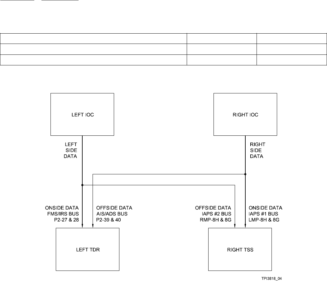
appendix C 523-0809018
Table C-12. Concentrated Bus Inputs
Bus Source TDR Bus TSS Bus
Onside data concentrator FMS/IRS IAPS #1
Cross-side data concentrator AIS/ADS IAPS #2
C.5.3.1. The following figure is of the expected concentrated bus architecture with a right TSS and a left TDR using a single output
bus from both the left and the right concentrator.
Figure C-1. Bus Architecture, TSS (R) and TDR (L)
C.5.3.2. A summary of the data sources that are sorted based on SDI is below. Data from all other sources are sorted by the bus
that the data is received.
• Radio Altimeter
• PFD
• ADC
• AHC/IRS.
C.5.3.3. Here is a list of the labels that can be received on the concentrated buses, the ultimate expected source of the data, and
notes regarding their use. Not Required does not mean that it is not desired or will not be used – it means that at this time it is not
a required parameter.
C-12

appendix C 523-0809018
Label Parameter Name Notes
076 GNSS Altitude (MSL) (GPS) May be on GPS bus
101 Selected Heading/Track Required for ADS-B
102 Selected Altitude Either this or label 226 required for enhanced surveillance;
102 used for selected altitude that comes from a source
other than the FMS
103 GPS Track Angle (GPS) Required for ADS-B, but may be on GPS bus
110 GNSS Latitude - Coarse (GPS) Required for ADS-B, but may be on GPS bus
111 GNSS Longitude - Coarse (GPS) Required for ADS-B, but may be on GPS bus
112 GNSS Ground Speed (GPS) Required for ADS-B, but may be on GPS bus
120 GNSS Latitude - Fine (GPS) Required for ADS-B, but may be on GPS bus
121 GNSS Longitude - Fine (GPS) Required for ADS-B, but may be on GPS bus
130 Horizontal Integrity Limit (GPS) Required for ADS-B, but may be on GPS bus
133 Vertical Integrity Limit (GPS) Required for ADS-B, but may be on GPS bus
136 Vertical Figure of Merit (GPS) Required for ADS-B, but may be on GPS bus
151 GNSS UTC (Time) (GPS) Required for ADS-B, but may be on GPS bus
164 Radio Height (RALT) Required
165 Vertical Velocity (GPS) Required for ADS-B, but may be on GPS bus
166 GNSS N/S Velocity (GPS) Required for ADS-B, but may be on GPS bus
174 GNSS E/W Velocity (GPS) Required for ADS-B, but may be on GPS bus
175 PFD Mode Select Word (PFD) Required; use bits 11, 12, 13, 15, & 25-28
203 Pressure Altitude (ADC) Required, but may be received on selected control bus
204 Baro-Corrected Altitude (ADC) May be on selected control bus
205 Mach (ADC) Required
206 Computed Airspeed (ADC) Required
210 True Airspeed (BNR) (ADC) Required
212 Altitude Rate (ADC) Required
213 Static Air Temperature (BNR) (ADC) Not required
217 Static Pressure (Hg) SSE Corrected (ADC) Not required
226 Target Altitude (From FMS) Either this or label 102 required for enhanced surveillance;
226 used for target altitude that comes from the FMS
240 Barometric Correction (ADC) Required
247 Horizontal Figure of Merit (GPS) Required for ADS-B, but may be on GPS bus
253 FGC Mode Word 2 (FGC) Required; only use bit 19
261 GNSSDate(GPS) MaybeonGPSbus
273 GNSS Sensor Status (GPS) Required for ADS-B, but may be on GPS bus
301 Aircraft Registry Word 1 (Central Maint) Not required
C-13

appendix C 523-0809018
Label Parameter Name Notes
302 Aircraft Registry Word 2 (Central Maint) Not required
303 Aircraft Registry Word 3 (Central Maint) Not required
310 Present Position Latitude (FMS) Not required, but desired as backup to GPS position
311 Present Position Longitude (FMS) Not required, but desired as backup to GPS position
312 Ground Speed (FMS) Required
313 Track Angle (True) (FMS) Required
314 True Heading (FMS) Not required
315 Wind Speed (FMS) Not required
316 Wind Direction (FMS) (Reserved) Not required
317 Track Angle, Magnetic (IRS) Not required
320 Magnetic Heading (AHC) Required must be magnetic heading, not displayed
heading
324 Pitch Angle (IRS) Not required
325 Roll Angle (IRS) Required
335 Track Angle Rate (IRS) Required, but known that it is not available on an AHRS
system; for new AHRS installations it is expected that the
FMS will calculate this value and it will be received as
label 336
336 Track Angle Rate (FMS) Required see above
365 Inertial Vertical Speed (IRS) Required, may be from FMS instead of IRS
366 North/South Velocity (FMS) Not required, but desired as backup to GPS velocity
367 East/West Velocity (FMS) Not required, but desired as backup to GPS position
370 GNSS Altitude (HAE) (GPS) Required for ADS-B, but may be on GPS bus
376 PFD Discrete Wd 2 (PFD) Required; using bits 27-28
C.5.4. GPS Input Data.
GPS Input Data section includes information about:
• GPS Bus Labels
•GPSDataLatency
• GPS Data/Time Mark Input Correlation
• Single vs Dual GPS Installation.
C.5.4.1. GPS Bus Labels. Refer to Table C-13 for a listing of the data used from the ARINC 429 data block coming from a
GPS.
Table C-13. GPS Bus Labels
Label Parameter Name
076 GNSS Altitude (MSL)
103 GPS Track Angle True
C-14

appendix C 523-0809018
Table C-13. GPS Bus Labels - Continued
Label Parameter Name
110 GNSS Latitude Coarse
111 GNSS Longitude Coarse
112 GNSS Ground Speed
120 GNSS Latitude Fine
121 GNSS Longitude Fine
130 Horizontal Integrity Limit
133 Vertical Integrity Limit
136 Vertical Figure of Merit
150 GNSS UTC Time
165 GPS Vertical Velocity
166 GNSS N/S Velocity
174 GNSS E/W Velocity
247 Horizontal Figure of Merit
260 GNSS Date
273 GNSS Sensor Status
370 GNSS Altitude (HAE)
C.5.4.2. GPS Data Latency. It is important that the GPS time mark (which comes out once a second) and the ARINC 429 data
block associated with it have less than a 200 ms lag between them. Typically, a high speed data block associated with the time
mark comes out about 150 ms after the time mark. A low speed data block comes out just under 200 ms. If there is not a direct
connection between the GPS and the TSS or TDR transponder, the latency through the rest of the system must be minimized. A
GPS may transmit data at either a 1 Hz rate or at a 5 Hz rate. Either input rate is acceptable for the transponders. GPS data may not
be down-sampled (for example, to one every 5 data blocks) as the block that corresponds to the time mark must be received by the
transponder.
C.5.4.3. GPS Data/Time Mark Input Correlation. GPS data may either come in through the dedicated GPS bus or through the
concentrated bus. It is not allowable to have the data come in through both. When received on the concentrated bus, GPS data is
sorted by the bus it comes in, so the data from the left GPS must come from the left concentrator and the data from the right GPS
must come from the right concentrator. In addition, the GPS Time Mark input being used must match the input of the ARINC 429
data. Refer to Table C-14 for which time mark matches which input port.
NOTE
For the TDR there is only one time mark input. Data received either from the cross-side GPS or the cross-side
concentrator will not have an associated time mark.
Table C-14. GPS Data/Time Mark Input Correlation
Unit Time Mark Input GPS Input Concentrated Bus Input
TSS GPS Time Mark #1 (LMP 9J & 9K) GPS #1 IAPS #1
TSS GPS Time Mark #2 (RMP 9J & 9K) GPS #2 IAPS #2
C-15
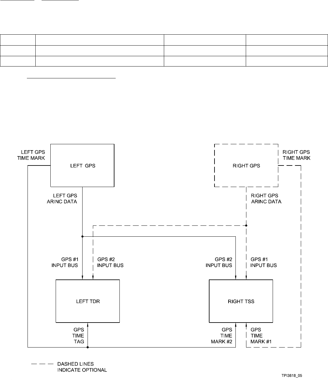
appendix C 523-0809018
Table C-14. GPS Data/Time Mark Input Correlation - Continued
Unit Time Mark Input GPS Input Concentrated Bus Input
TDR GPS Time Tag (P2-37 & 38) GPS #1 FMS/IRS
TDR None GPS #2 AIS/ADS
C.5.4.4. Single vs Dual GPS Installation. Refer to Figure C-2 for an example block diagram of a GPS installation. In this
diagram the Left GPS is standard and the right GPS is optional.
NOTE
There is an ECU setting for the TSS as to whether there should be one or two GPS inputs expected.
In a single GPS installation, a right TSS expects that the single GPS input to come in from the cross side – to come
in on the #2 input.
Figure C-2. Dual GPS Installation
C-16

appendix C 523-0809018
C.5.5. XT-2 Input Bus (TDR to TSS).
Refer to Table C-15 for a list of the labels received on the XT-2 input bus.
NOTE
The TSS only supports the DO-185A XT/TX protocol; it does not support the older TSO C119A protocol.
Table C-15. XT-2 Input Bus (TDR to TSS)
Label Parameter Name
013 TCAS Control Word
015 TCAS Altitude Select Limits
016 TCAS/Mode-S Transponder
203 Pressure Altitude (XT Word 4)
204 Baro-Corrected Altitude (XT Word 9)
270 XGD Protocol (XT Word 10) (Reserved)
271 XT Word 1
272 XT Word 2
273 XT Word 3
274 XT Word 8
275 XT Word 5
276 XT Word 6
277 XT Word 7
C.5.6. TSS Data Load Bus.
Refer to Table C-16 for a list of the labels received on the data load input bus.
Table C-16. TSS Data Load Bus
Label Parameter Name
027 TSS Data Load Receive (Dataloader)
227 ARINC 604 from CMS
C-17/(C-18 Blank)

523-0809018
APPENDIX D
Equipment Characteristics
D.1. EQUIPMENT CHARACTERISTICS.
Refer to Table D-1 for the equipment specifications. Refer to Table D-2 for the certification categories. Refer to Table D-3 for the
equipment weight, power requirements, and size. Refer to Table D-4 through Table D-8 for the environmental qualifications of each
piece of equipment.
Table D-1. Equipment Specifications.
CHARACTERISTIC SPECIFICATION
Certification
FAA Technical Standard
Order (TSO)
Refer to Table D-2.
Environmental Refer to Table D-2 and to the environmental qualification forms provided in Table D-4
through Table D-8.
Size Refer to Table D-3.
Weight Refer to Table D-3.
Power requirements Refer to Table D-3 (typical values).
Maintenance requirements The TCAS function of the TSS-4100 does not require any periodic maintenance -- it is on
condition. The exception follows:
TSS-4100 and TDR-94D: The transponder function must have an Air Traffic
Control (ATC) transponder test and inspection according to FAR part 91 at a minimum
of once every two years.
D-1

appendix D 523-0809018
Table D-2. Certification Categories.
Unit FAA TSO Environmental Categories
ANT-42 C66b,C74c DO-160A E1/B/JLY/XRHXXXXXXXX
ECU-3000 TSO-C112 & TSO-C119b (-802
status)+ TSO-C166a Transmit only
(-803 status)
DO-160E [(F2)(A2)V]ABB[(RBB1)(SCLM)(HR)]
EYXXXXZ[AB]AZ[CC] [RR]M[X][X]AAX
TDR-94D TSO-C112 Class 3A2 121 011 Level
3es
DO-160E [(A2)(E1)-]BBA[SCLM] EXXXFXZZAZZC
[RR]M[(A3)(Z3)X]XXAX
TRE-930 C66, C74 DO-108 ABAXXXXCL1
NOTE
This unit is not tested to DO-160 levels.
TSA-4100 TSO-C112, TSO-C119b &
TSO-C166a Transmit only.
DO-160E [(D2)(F2)X]ABB[(RCC1)(HR)(SLM)]
XSFDFSZ[X]XX[CW] [RR]H[(XX)(K4)4][1A]AAX
TSS-4100 TSO-C112 Class 2A1 121 011 Level
2es, TSO-C119b & TSO-C166a
Transmit Only
DO-160E [(F2)(A2)V]ABB[(RBB1)(SCLM)(HR)]
EYXXXXZ[AB]AZ[CC] [RR]M[(B3)(K3)3]XAAX
Table D-3. Unit Weight, Power Requirements, and Size.
UNIT WEIGHT
kg (lb)
POWER
(Nominal)
POWER
(Max) SIZE(H×W×L)mm(in)
ANT-42 96 (0.2) Not
Applicable (NA)
84.1 x 44.5 x 115.3 (3.31 x 1.75 x 4.45)
TSA-4100 1.0 (2.2) NA 33.0 x 160 x 284.5 (1.30 x 6.30 x 11.20)
NOTE
Height does not include length of connector. The
-101 connector is 20 mm long. The -001 connec-
tor is 39 mm long.
ECU-3000 0.08 (0.17) Powered by
TSS-4100
36x51x70(1.4x2.0x2.8)
TDR-94/94D 3.86 (8.5) 28.0 W 85.0 x 124 x 353 (3.31 x 4.87 x 14.0) (1/2 ATR,
short-low)
TRE-930 0.17 (0.38) NA 84 x 44 x 133 (3.3 x 1.7 x 5.24)
TSS-4100 7.55 (16.6) 85 W 120 W 194 x 129 x 382 (7.64 x 5.08 x 15.0)
D-2

appendix D 523-0809018
Table D-4. ANT-42 Environmental Qualification Form.
CONDITIONS DO-160A SECTION
AND REV
EQUIPMENT QUALIFICATIONS
CATEGORIES OF CONDUCTED TESTS
Temperature and Altitude 4.0 Category E1
-Temperature
- Low Operating Temperature –55 °C (+5 °F)
- High Operating Temperature +70 °C (+158 °F)
- Low Storage Temperature –55 °C (-67 °F)
- High Storage Temperature +85 °C (+185 °F)
- Altitude E1
Temperature Variation 5.0 B
Humidity 6.0 J
Shock 7.0 L
- Operational
- Crash Safety
Vibration 8.0 Y
Explosion 9.0 X
Waterproofness 10.0 R
Fluids Susceptibility 11.0 H
Sand and Dust 12.0 X
Fungus 13.0 X
Salt Spray 14.0 X
Magnetic Effect 15.0 X
Power Input 16.0 X
Voltage Spike Conducted 17.0 X
Audio Frequency Conducted Susceptibility 18.0 X
Induced Signal Susceptibility 19.0 X
Radio Frequency Susceptibility 20.0 X
D-3

appendix D 523-0809018
Table D-5. ECU-3000 Environmental Qualification Form.
CONDITIONS DO-160E SECTION
AND REV
EQUIPMENT QUALIFICATIONS
CATEGORIES OF CONDUCTED TESTS
Temperature and Altitude 4.0 (F2)(A2)V
- Temperature
- Low Operating Temperature F2 –55 °C (–67 °F)
- High Operating Temperature F2 +70 °C (+158 °F)
- Low Storage Temperature F2 –55 °C (–67 °F)
- High Storage Temperature F2 +85 °C (+185 °F)
- High (Short Time) Operating Temperature F2 +70 °C (+158 °F)
- Altitude F2 16 800 m (55 000 ft)
- In-Flight Loss of Cooling V
- Decompression A2
- Over pressure A2
Temperature Variation 5.0 A
Humidity 6.0 B
Shock 7.0 B
- Operational Tested at 6 g peak
- Crash Safety Tested at 20 g peak
Vibration 8.0 Equipment Tested to Cat R curves BB1, Cat S
curves CLM and Cat H curve R
Explosion Proofness 9.0 E
Waterproofness10.0
Y
Fluids Susceptibility 11.0 X
Sand and Dust 12.0 X
Fungus Resistance 13.0 X
Salt Spray 14.0 X
Magnetic Effect 15.0 Z
Power Input 16.0 AB
Voltage Spike 17.0 A
Audio Frequency Conducted Susceptibility 18.0 Z
Induced Signal Susceptibility 19.0 CC
Radio Frequency Susceptibility 20.0 RR
Emission of Radio Frequency Energy 21.0 M
Lightning Induced Transient Susceptibility 22.0 X
Lightning Direct Effects 23.0 X
Icing 24.0 A
Electrostatic Discharge 25.0 A
D-4

appendix D 523-0809018
Table D-5. ECU-3000 Environmental Qualification Form. - Continued
CONDITIONS DO-160E SECTION
AND REV
EQUIPMENT QUALIFICATIONS
CATEGORIES OF CONDUCTED TESTS
Fire/Flammability 26.0 X
NOTE
The ECU-3000 Power Input is tested to the worst case of categories A, B, and Z with the exception of the 1 second power interruption
test required for category Z.
D-5

appendix D 523-0809018
Table D-6. TDR-94D Environmental Qualification Form.
CONDITIONS DO-160E SECTION
AND REV
EQUIPMENT QUALIFICATIONS
CATEGORIES OF CONDUCTED TESTS
Temperature and Altitude 4.0 A2 and E1
-Temperature
- Low Operating Temperature –55 °C (–67 °F)
- High Operating Temperature +70 °C (+158 °F)
- Low Storage Temperature –55 °C (–67 °F)
- High Storage Temperature +85 °C (+185 °F)
- Altitude 21 300 m (70 000 ft)
- In-Flight Loss of Cooling - (Not applicable)
Temperature Variation 5.0 B
Humidity 6.0 B
Shock 7.0 A
- Operational Tested at 6 g peak
- Crash Safety Tested at 15 g (11 ms duration)
Vibration 8.0 Equipment Tested to Cat S, curves CLM
Explosion 9.0 E
Waterproofness 10.0 X
Fluids Susceptibility 11.0 X
Sand and Dust 12.0 X
Fungus 13.0 F
Salt Spray 14.0 X
Magnetic Effect 15.0 Z
Power Input 16.0 Z
Voltage Spike Conducted 17.0 A
Audio Frequency Conducted Susceptibility 18.0 Z
Induced Signal Susceptibility 19.0 ZC
Radio Frequency Susceptibility 20.0 RR
Radio Frequency Emission 21.0 M
Lightning Induced Transient Susceptibility 22.0 A3Z3X
Lightning Direct Effects 23.0 X
Icing 24.0 X
Electrostatic Discharge 25.0 A
Flammability 26.0 X
Electrical NA
Primary Power 28 V DC, 28 W nominal, 100
Wmax
Receive Frequency NA
D-6

appendix D 523-0809018
Table D-6. TDR-94D Environmental Qualification Form. - Continued
CONDITIONS DO-160E SECTION
AND REV
EQUIPMENT QUALIFICATIONS
CATEGORIES OF CONDUCTED TESTS
1030 ±0.2 MHz from ATCRBS interrogators
1030 ±0.01 MHz from Mode-S interrogators
Transmit Frequency NA
1090 ± 1 MHz
Transmit Peak Power NA
min250W,max625W
D-7

appendix D 523-0809018
Table D-7. TSA-4100 Environmental Qualification Form.
CONDITIONS DO-160E SECTION
AND REV
EQUIPMENT QUALIFICATIONS
CATEGORIES OF CONDUCTED TESTS
Temperature and Altitude 4.0 (D2)(F2)X
- Temperature
- Low Short Time Operating Temperature D2
- Low Operating Temperature D2
- High Short Time Operating Temperature D2
- High Operating Temperature D2
- Altitude F2
Temperature Variation 5.0 A
Humidity 6.0 B
Shock 7.0 B
Vibration 8.0 Equipment Tested to Cat R curves CC1, Cat H
curve R and Cat S curves LM (RCC1)(HR)(SLM)
Explosion 9.0 X
Waterproofness 10.0 S
Fluids Susceptibility 11.0 F
Sand and Dust 12.0 D
Fungus 13.0 F
Salt Spray 14.0 S
Magnetic Effect 15.0 Z
Power Input 16.0 X
Voltage Spike Conducted 17.0 X
Audio Frequency Conducted Susceptibility 18.0 X
Induced Signal Susceptibility 19.0 CW
Radio Frequency Susceptibility 20.0 RR
Radio Frequency Emission 21.0 H
Lightning Induced Transient Susceptibility 22.0 (XX)(K4)4
Lightning Direct Effects 23.0 1A
Icing 24.0 A
Electrostatic Discharge 25.0 A
Fire/Flammability 26.0 X
DC Input Resistance: NA
J1 to ground - 1.2 M
J2 to ground - 680 k
J3 to ground - 390 k
NOTE
These values are used by the TSS-4100 during initializa-
tion to verify proper antenna connections J4 to ground - 220 k
D-8

appendix D 523-0809018
Table D-8. TSS-4100 Environmental Qualification Form.
CONDITIONS DO-160E SECTION
AND REV
EQUIPMENT QUALIFICATIONS
CATEGORIES OF CONDUCTED TESTS
Temperature and Altitude 4.0 [(F2)(A2)V]
- Temperature
- Low Temperature Storage F2
- High Temperature Operation F2
- High Temperature Storage F2
- Low Temperature Operation F2
- In-Flight Loss of Cooling V
- Altitude F2
- Decompression A2
- Overpressure A2
Temperature Variation 5.0 A
Humidity 6.0 B
Shock 7.0 B
- Operational
- Crash Safety
Vibration 8.0 Equipment Tested to Cat R curves BB1, Cat S
curves CLM andCatHcurveR
Explosion 9.0 E
Waterproofness 10.0 Y
Fluids Susceptibility 11.0 X
Sand and Dust 12.0 X
Fungus 13.0 X
Salt Spray 14.0 X
Magnetic Effect 15.0 Z
Power Input 16.0 AB
Voltage Spike Conducted 17.0 A
Audio Frequency Conducted Susceptibility 18.0 Z
Induced Signal Susceptibility 19.0 CC
Radio Frequency Susceptibility 20.0 RR
Radio Frequency Emission 21.0 M
Lightning Induced Transient Susceptibility 22.0 (B3)(K3)3
Lightning Direct Effects 23.0 X
Icing 24.0 A
Electrostatic Discharge 25.0 A
Fire/Flammability 26.0 X
TCAS RF Characteristics NA
D-9

appendix D 523-0809018
Table D-8. TSS-4100 Environmental Qualification Form. - Continued
CONDITIONS DO-160E SECTION
AND REV
EQUIPMENT QUALIFICATIONS
CATEGORIES OF CONDUCTED TESTS
Transmit Frequency 1030 ± 0.01 MHz
Receive Frequency 1090 ± 3 MHz
Sensitivity 75 ± 1 dBm
XPDR RF Characteristics NA
Receive Frequency (XPDR) 1030 ± 0.2 MHz
Transmit Frequency 1090 ± 1 MHz
Transmit Peak Power min 125 W, max 500 W
Sensitivity 74 ± 3 dBm
Electrical NA
Primary Power 28 V DC, 85 W nominal, 120
Wmax
Inrush current – 40 amps max
1.875 microhenry inductor
NOTE
The TSS-4100 has been tested to the highest level of power input testing of Category A, B, and Z – with the exception of a one second
power interrupt test required for Category Z.
The TSS-4100 has undergone flammability testing/ analysis that meets Rockwell Collins standard CS-ENG-M-122: Flammability, Toxi-
city, and Smoke Density Analysis Method.
D-10

523-0809018
APPENDIX E
Interconnect Diagram
E.1. INTRODUCTION.
This appendix contains the interconnect wiring diagram. Refer to Figure E-1.
E.2. CABLING INSTRUCTIONS.
Make sure the aircraft battery master switch is turned off before installing any interconnect cabling.
NOTE
Figure E-1 shows a possible interconnect between the TSS-4100 and various altitude and control sources. Because
various part numbers of the TSS-4100 provide different strapping options this information is for reference only.
The Traffic Surveillance System (TSS) interconnect diagram is shown in Figure E-1. All installations follow this general configu-
ration pattern. Various options offer the installer a wide choice of configurations for new and retrofit installations. Use the generic
interconnect diagram to help locate specific interconnect data. Each functional area, shown in bold type, is complete only with
respect to TSS interface data for that particular function. That is, for peripheral systems, for example the air data system or radio
altimeter system, interconnect data to non-TSS related equipment is not provided here. In those cases, you must refer to other appro-
priate documentation. Most of the application groupings are also shown in bold type. Subordinate application groupings are shown
in normal type.
During preparation of the interconnect cables, observe the precautions that follow:
a. Read all notes on drawings and interconnect diagrams prior to fabricating interconnect wiring cables.
b. Bond and shield all parts of the aircraft electrical system, such as generator and ignition systems.
c. Keep the interconnect cables away from circuits carrying heavy current, pulse transmitting equipment, and other sources of
information.
d. Make all external connections of the equipment through the designated connectors listed on the outline and mounting diagrams.
e. For balanced connections, use twisted-pair shielded wiring for minimum pickup of electrostatic and magnetic fields. Avoid
long runs of wire and keep input and output circuits separated as much as possible.
f. All interconnect wires and cables should be marked in accordance with the Aircraft Electronics Association Wire Marking
Standard.
g. Avoid excessive cable lengths, but allow sufficient slack for movements due to vibration.
h. After installation of the cables in the aircraft, and before installation of the equipment, check to make sure that aircraft power
is applied to the pins specified on the interconnect diagrams and that all other wires and shields are properly terminated.
E.3. GROUNDING AND HIRF GUIDELINES.
The notes on the system interconnect wiring diagram (refer to Figure E-1, sheet 1) describe the recommended methods and tech-
niques for reducing the hazards of High Intensity Radiated Field (HIRF). These are general recommendations that apply to wiring
modification/repair as well as to new installations. It shows the preferred method for grounding the shields of shielded wires.
E-1

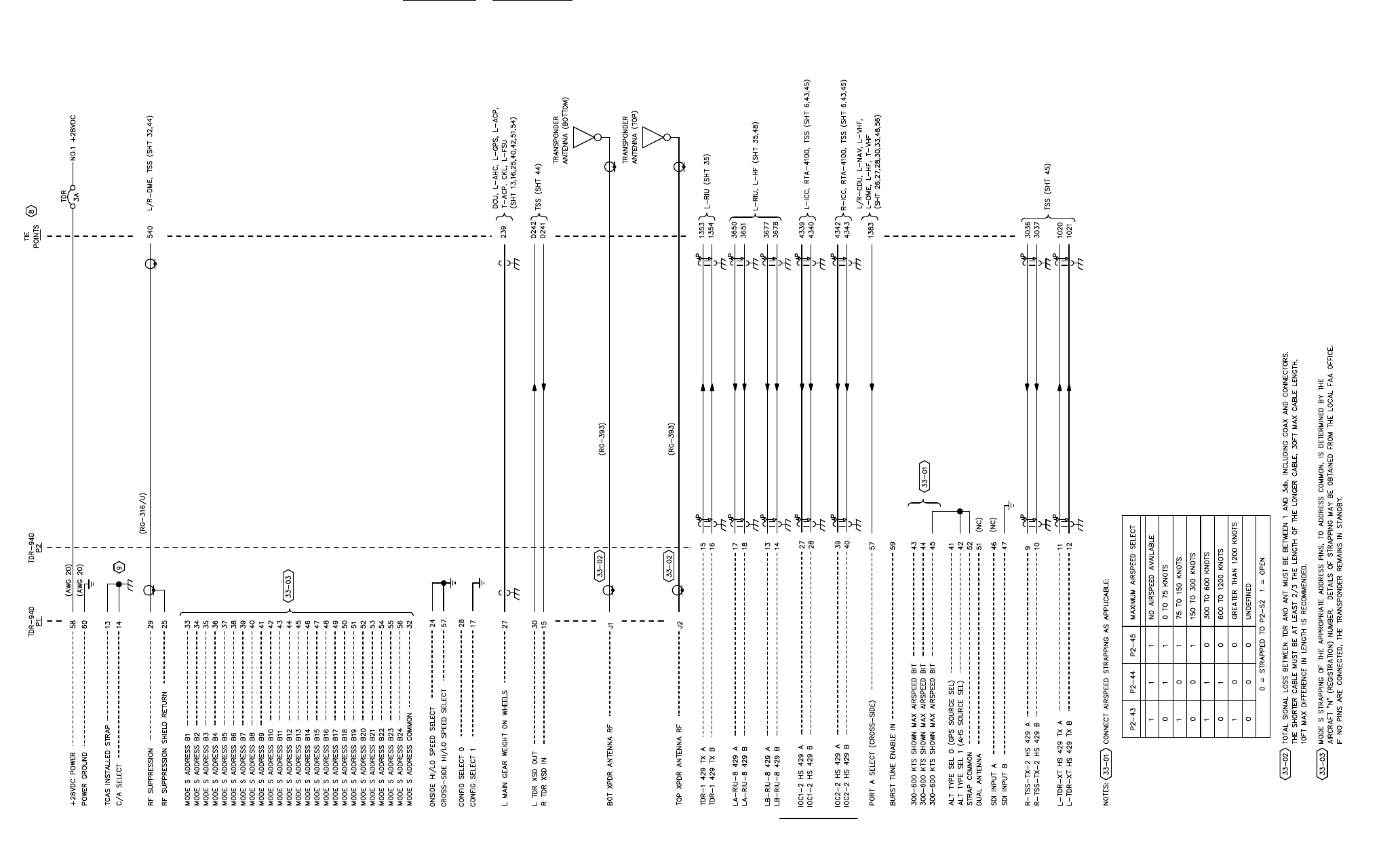
appendix E 523-0809018
(992-6037-001B_33)
TPJ9606_01
Figure E-1. Traffic Surveillance System, Interconnect Wiring Diagram (Sheet 1 of 3)
E-3/(E-4 Blank)
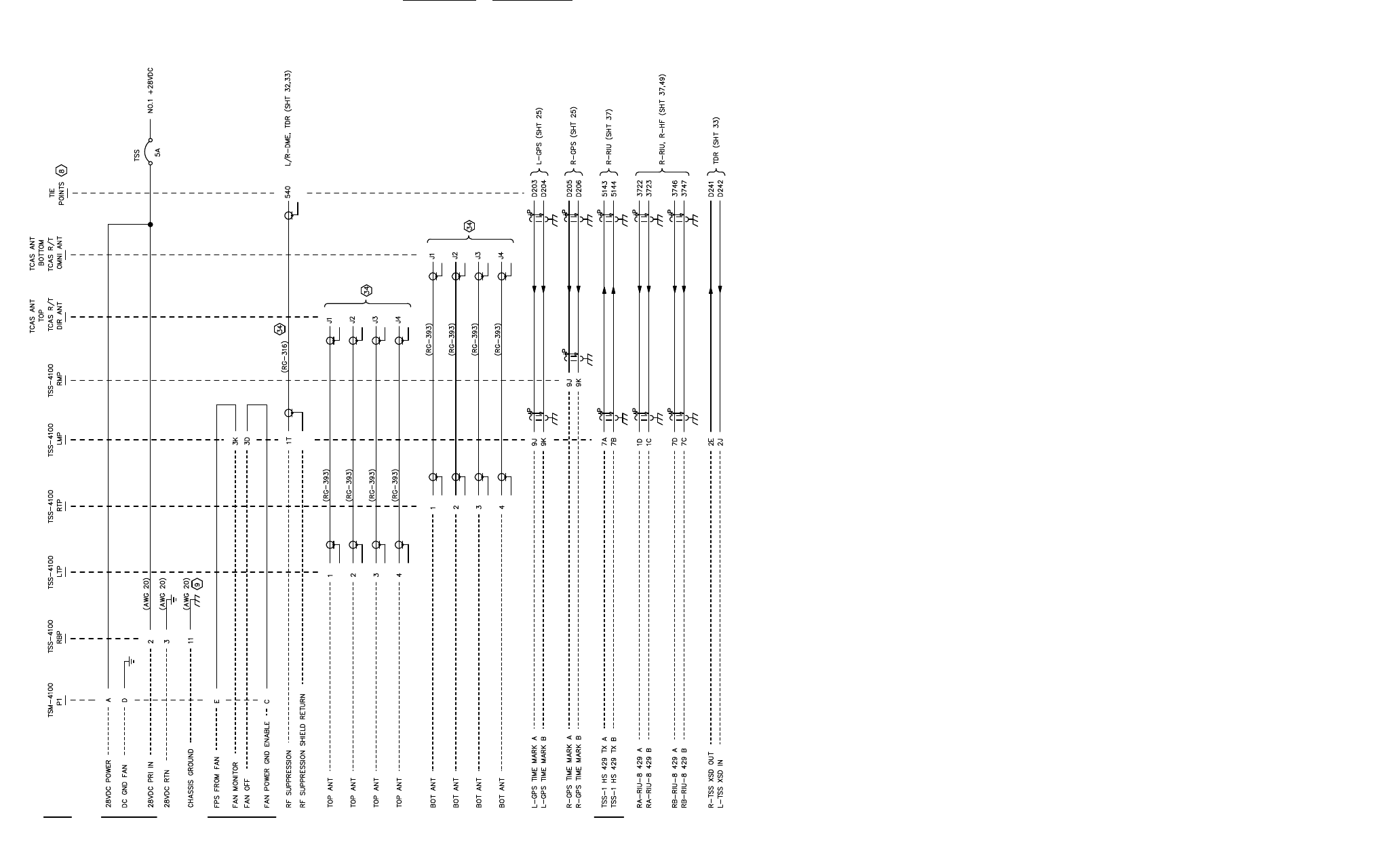
appendix E 523-0809018
(992-6037-001B_44)
TPJ9606_02
Figure E-1. Traffic Surveillance System, Interconnect Wiring Diagram (Sheet 2 of 3)
E-5/(E-6 Blank)
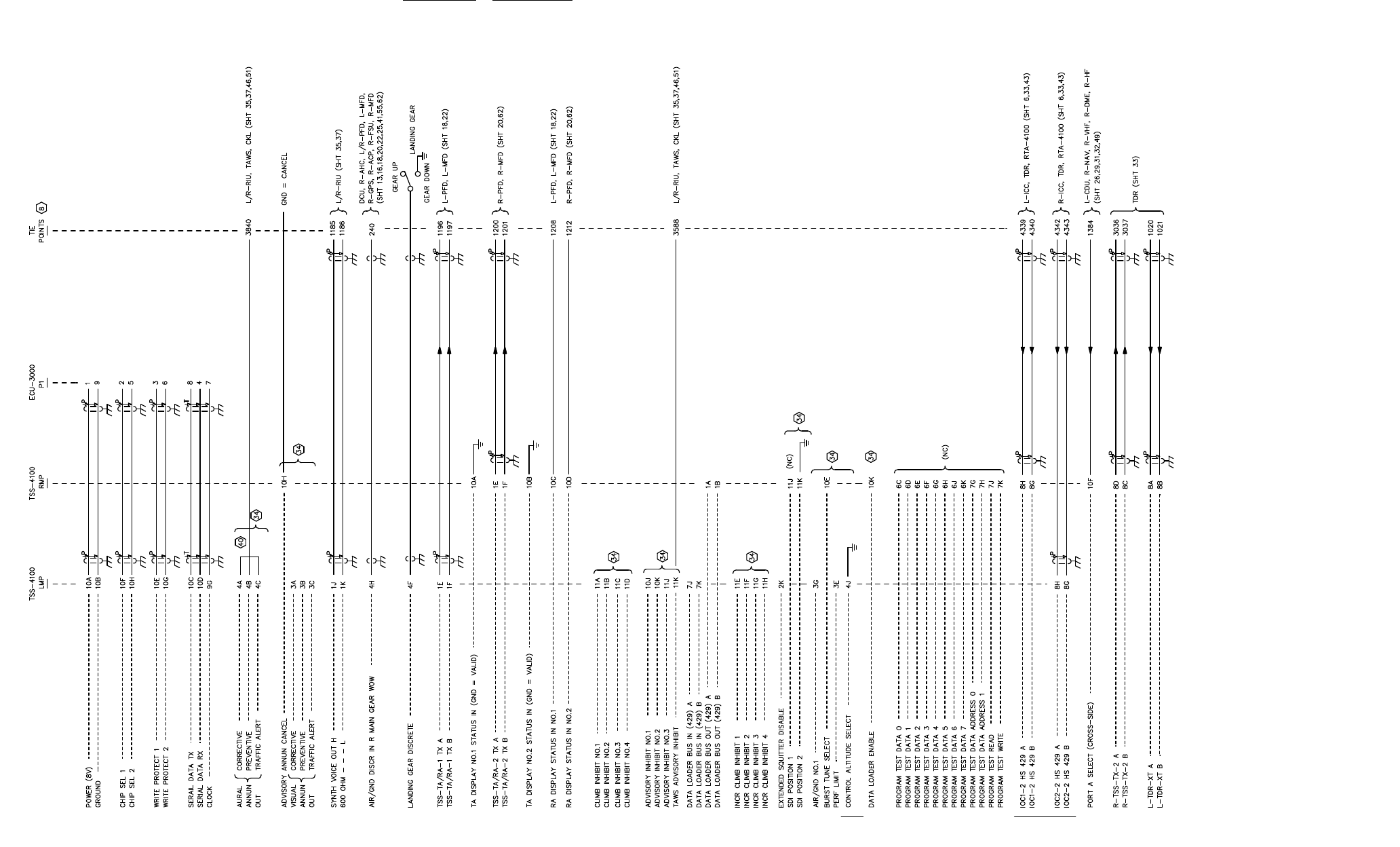
appendix E 523-0809018
(992-6037-001B_45)
TPJ9606_03
Figure E-1. Traffic Surveillance System, Interconnect Wiring Diagram (Sheet 3 of 3)
E-7/(E-8 Blank)

523-0809018
© Copyright 2009, Rockwell Collins, Inc.,
All Rights Reserved, Printed in USA