Rockwell Collins PN822-2764 HF TRANSCEIVER User Manual Rockwell Collins Inc
Rockwell Collins Inc HF TRANSCEIVER Rockwell Collins Inc
UserManual.wiki
>
Rockwell Collins
>
PN822 2764 User Manual
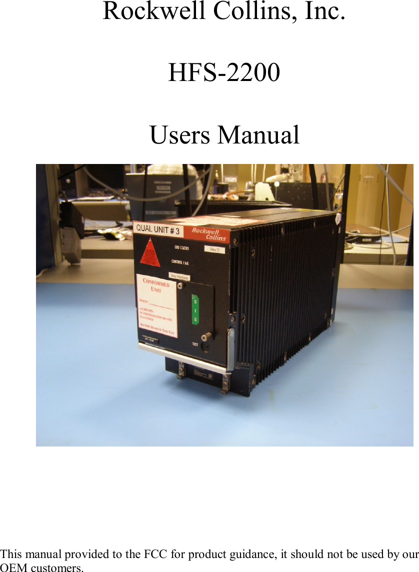
Users Manual
Navigation menu
Upload a User Manual
Namespaces
Wiki Guide
HTML
PDF
Info
Views
User Manual
Discussion / Help
Navigation