Rockwell Collins PN822-2764 HF TRANSCEIVER User Manual Rockwell Collins Inc
Rockwell Collins Inc HF TRANSCEIVER Rockwell Collins Inc
Users Manual
Rockwell Collins, Inc.
HFS-2200
Users Manual
This manual provided to the FCC for product guidance, it should not be used by our
OEM customers.
Scope:
This document will detail information required to install and use the HFS-2200 unit.
Introduction:
The Rockwell Collins® HFS-2200 HF Data Radio (HFDR) provides the means to
process transmit and receive data as well as analog voice. The HFDR transceiver
operates on frequencies spaced 100 Hz apart in the 2-30-MHz band. For compatibility
with existing ARINC 719 installations the HFS-2200 provides single sideband
suppressed carrier voice, amplitude modulated equivalent voice, selective calling
(SELCAL™), and analog data functions. In addition to providing traditional HF radio
functionality, the unit contains an internal data modem and controller for ARINC 753
compatibility. Voice transmission is compatible with current single sideband HF
transceivers. Data transmission is compatible with ground HF transmitting and receiving
systems, which use conventional HF transceivers and ARINC 635 compliant modems
and controllers.
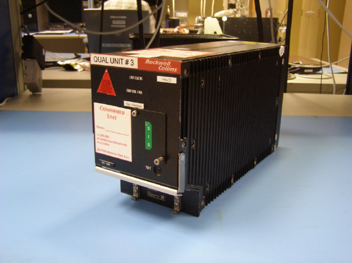
Mechanical Description
The HFS-2200 is structured with formed aluminum members that include a front panel, a
rear panel, a bottom panel, a top panel, a central partition that rigidly maintains the
alignment of the other panels, and a swing-out side panel.
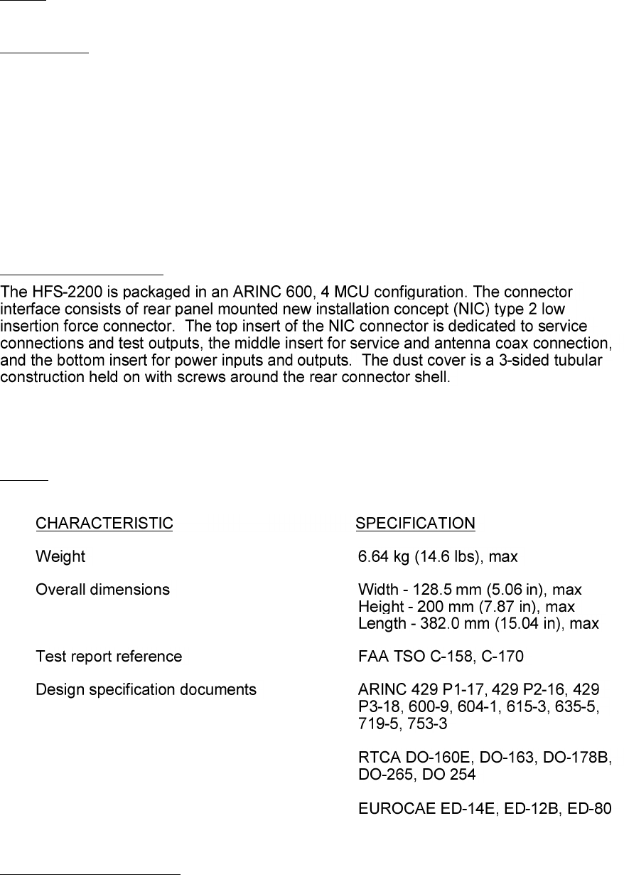
Design
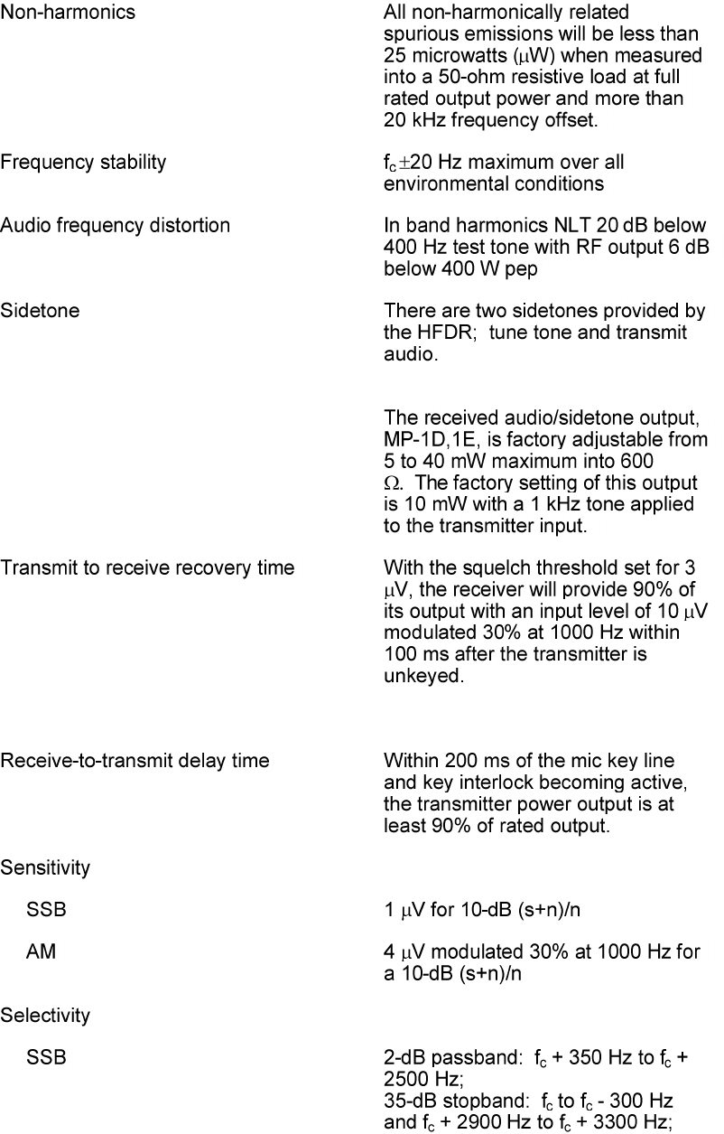
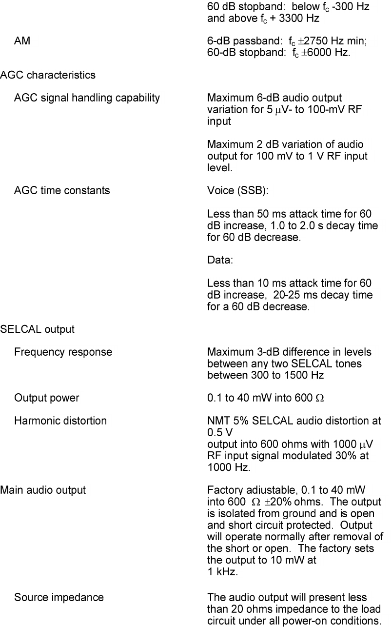
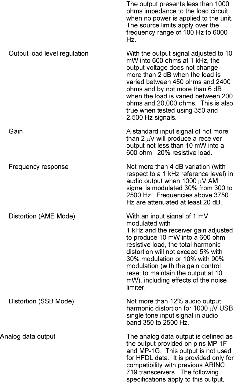
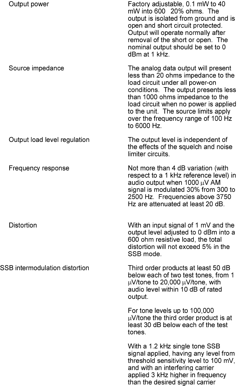
The table below details the characteristics of the HFS-2200.
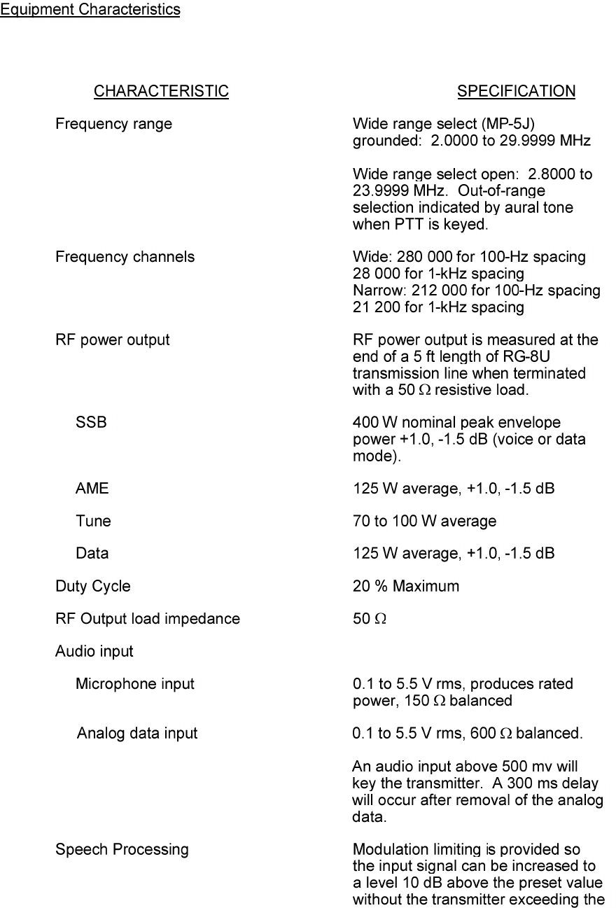
Equipment Characteristics
The HFS-2200 conforms to the following equipment specifications listed in figure 6
according to DO-163, ARINC 635, ARINC 719-5, and ARINC 753-3.
±
±
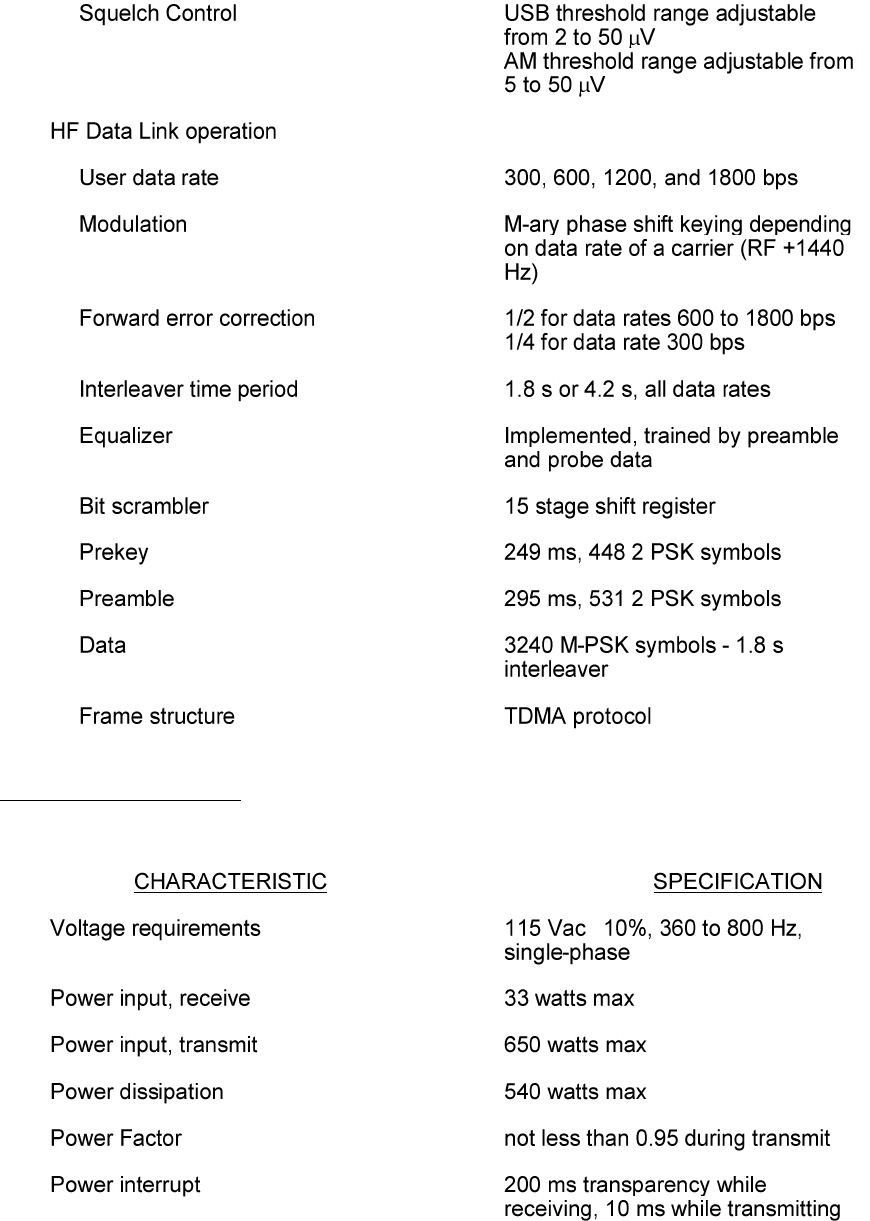
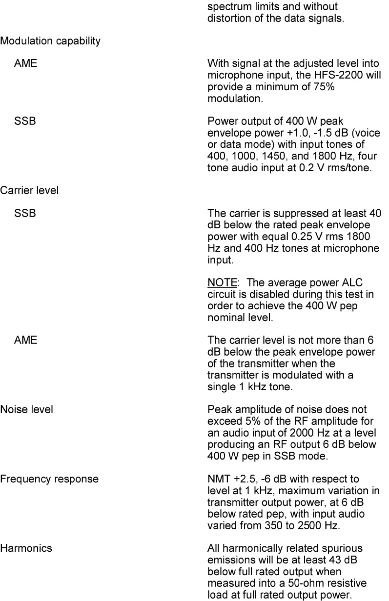
Electrical Characteristics
The HFS-2200 conforms to the following electrical specifications;
±
Installation:
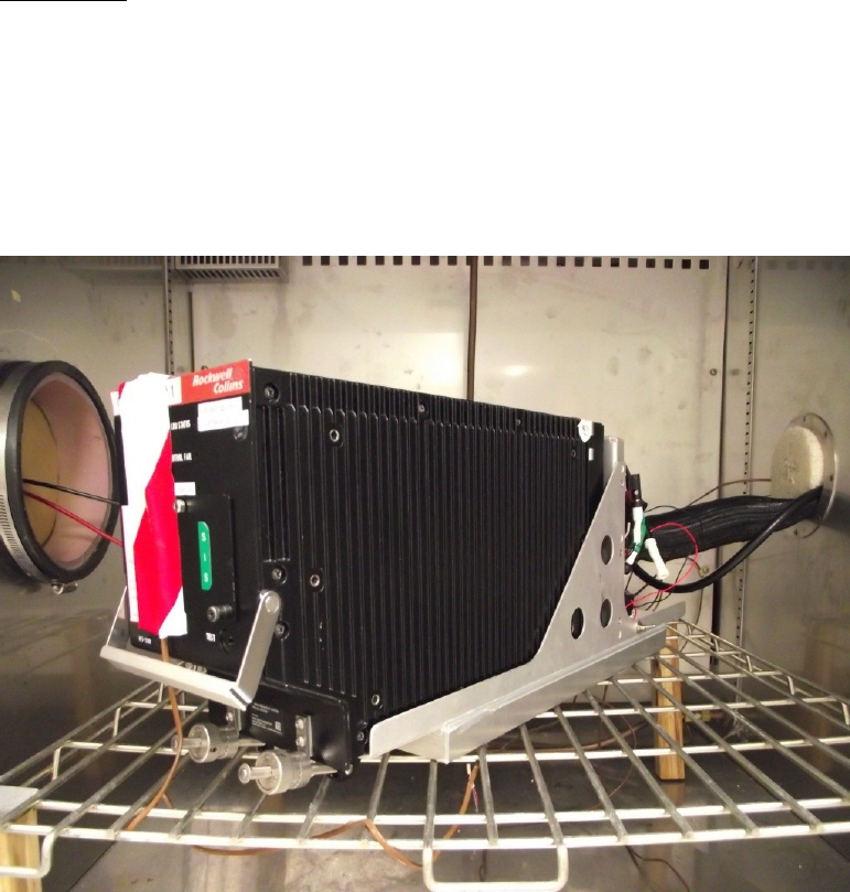
The picture below details the HFS-2200 unit mounted in the ARINC 600 4MCU mount.
These type mounts have mechanical mechanisms to allow capture and restraint of the
front feet of the unit. This restraint ensures the unit will not come loose from the mount
and also that the ARINC defined connector does remains in contact with the rear pins.
The harness that connects the RMP to the VHF-2200 is defined by the aircraft
manufacturer. The pinout is defined by the ARINC 753 and 719 standard to allow
interchangeable product migration. The HFS-2200 pinout can be found below.
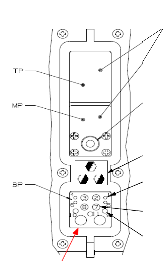
Rear Pin Out
Error! Reference source not found.The following pictures provide a generic depiction
of the HFS-2200 rear connector. The top, middle and bottom insert will be defined later
in this chapter.
N um b e r 22 socke ts
N um b e r 1 C oaxia l C onta ct
In d e x P in C o d in g #53
N um b e r 20 pin conta ct
N um b e r 12 pin conta ct
N um b e r 16 pin conta ct
HFS-2200 Rear Connector Layout (not to scale)

A
B
C
D
E
F
G
H
J
K
1
RS232 TX
RS232
RX
SPARE1
SPARE2
MFG
Reserved
MFG
Reserved
MFG
Reserved
MFG
Reserved
MFG
Reserved
MFG
Reserved
2
RS232
Ground
ATE ID
ATE ID
MFG
Reserved
MFG
Reserved
MFG
Reserved
MFG
Reserved
MFG
Reserved
Serial No.
Load
MFG
Reserved
3
Strap Even
Parity
ICAO #1
429 Input
A
ICAO #1
429 Input
B
CFDS
Mode A
CFDS
Mode B
CFDS
Mode C
HFDL TX
Inhibit
Sense Input
HFDL TX
Inhibit
Program Input
MFG
Reserved
Opposite
Side HFDL
Mode
Enabled
4
MFG
Reserved
MFG
Reserved
MFG
Reserved
MFG
Reserved
MFG
Reserved
MFG
Reserved
MFG Spare
MFG
Reserved
MFG Spare
MFG
Reserved
5
CMU #1/2
A429 Bus
Speed
Select
Air/Gnd
Prog
Discrete
FAX Input
Reserved
FAX Input
Reserved
FAX Output
Reserved
FAX Output
Reserved
HFDR
Crosslink
Output A
HFDR
Crosslink
Output B
HFDR
Crosslink
Input A
HFDR
Crosslink
Input B
6
MFG
Reserved
MFG
Reserved
MFG
Reserved
MFG
Reserved
MFG
Reserved
MFG
Reserved
MFG Spare
MFG
Reserved
MFG
Reserved
MFG
Reserved
7
Time 429
Input A
Time 429
Input B
ICAO #2
429 Input
A
ICAO #2
429 Input B
Position
429 Input
A
Position
429 Input
B
HFDL Mode
Enable
Data Link Fault
Discrete
Output
HFDL TX
Inhibit
Override
Other Side
PTT
8
MFG
Reserved
MFG
Reserved
MFG
Reserved
MFG
Reserved
MFG
Reserved
MFG
Reserved
MFG
Reserved
MFG
Reserved
MFG
Reserved
MFG
Reserved
9
CMU #1
429 Input
A
CMU #1
429
Input B
CMU
429
Output A
CMU
429
Output B
CMU #2
429 Input
A
CMU #2
429 Input
B
MFG
Reserved
MFG
Reserved
HFDL TX
Inhibited
Discrete
Output
MFG
Reserved
10
MFG
Reserved
MFG
Reserved
MFG
Reserved
MFG
Reserved
MFG
Reserved
MFG
Reserved
MFG
Reserved
MFG
Reserved
MFG
Reserved
Double Beep
11
Data
Loader 429
Input A
Data
Loader
429 Input
B
Data
Loader
429
Output A
Data
Loader 429
Output B
Data Load
Discrete
Input
ICAO ID 1
(MSB)
ICAO ID 2
ICAO ID 3
ICAO ID 4
ICAO ID 5
12
MFG
Reserved
MFG
Reserved
MFG
Reserved
MFG
Reserved
MFG
Reserved
MFG
Reserved
MFG
Reserved
MFG
Reserved
MFG
Reserved
MFG
Reserved
13
ICAO ID 6
ICAO ID
7
ICAO ID 8
ICAO ID 9
ICAO ID 10
ICAO ID 11
ICAO ID 12
ICAO ID 13
ICAO ID 14
ICAO ID 15
14
MFG
Reserved
MFG
Reserved
MFG
Reserved
MFG
Reserved
MFG
Reserved
MFG
Reserved
MFG Spare
MFG
Reserved
MFG Spare
Maintenance
Mode
15
ICAO ID 16
ICAO ID
17
ICAO ID
18
ICAO ID 19
ICAO ID 20
ICAO ID 21
ICAO ID 22
ICAO ID 23
ICAO ID 24
(LSB)
ICAO Even
Parity Strap
HFS-2200 Top Plug

A
B
C
D
E
F
G
H
J
K
1
MIC Input
- HI
MIC Input-
LO
MIC PTT
- HI
IN / OUT
Audio/Sidetone
Output - HI
Audio/Sidetone
Output - LO
Analog
Data
Output -
HI
Analog
Data
Output -
LO
Analog
Data
Input - HI
Analog
Data Input
- LO
Analog
Data
Keyline
2
Reserved
Audio
Ground
MIC PTT
- LO
Voice/Analog
Data Mode
Select
Key Event
Discrete
Output
MIC
Input- LO
753 Spare
753
Spare
Fuel
Operations
Frequency
Source
Select
3
SSB/AM
Discrete
Input
LSB/USB
Discrete
Input
SELCAL
Output -
HI
SELCAL
Output - LO
Tuning Port A
429 Input - A
Tuning
Port A
429 Input
- B
Tuning
Port B 429
Input - A
Tuning
Port B
429 Input
- B
Frequency
Port Select
Input
Blower
Control
Input
4
CFDS
429 Input
A
CFDS 429
Input B
CFDS
429
Output A
CFDS 429
Output B
Coupler Fault
RF Fault
Air/Ground
Discrete
Input
SDI Input
#1
SDI Input
#0
SDI /
ICAO ID
Common
5
Chopper
Control
Rechannel
Output HF
RTS/CTS
Tune
Power
Input CPL
RTS/CTS
On/Off Relay
RF Squelch
RF
Sensitivity
753 Spare
Key
Relay
Interlock
& Serial
Data LO
Narrow /
Wide
Range
Select
Reserved
-
Reentrant
Tune A
6
Reserved
-
Reentrant
Tune B
Reserved
-
Reentrant
Tune C
Reserved
-
Reentrant
Tune D
Reserved -
Reentrant
Tune E
Reserved -
Reentrant
Tune F
Reserved
-
Reentrant
Tune G
Reserved -
Reentrant
Tune H
Reserved
-
Reentrant
Tune J
Reserved -
Reentrant
Tune K
Reserved
-
Reentrant
Tune L
7
Reserved
-
Reentrant
Tune M
Reserved
-
Reentrant
Tune N
Reserved
-
Reentrant
Tune P
Reserved -
Reentrant
Tune R
Reserved -
Reentrant
Tune S
Reserved
-
Reentrant
Tune T
Reserved -
Reentrant
Tune W
Reserved
-
Reentrant
Tune X
Reserved -
Reentrant
Tune r
Reserved
-
Reentrant
Tune j
HFS-2200 Middle Plug

4
3 2
1
65
7
8
910
11
12
13
HFS-2200 Bottom Plug View
Bottom Plug
BP-1
Interlock Excitation
753 Serial Data HI
BP-2
115 VAC Input / Output
BP-3
115 VAC Input / Output
BP-4
115 VAC Input / Output
BP-5
115 VAC Input / Output
BP-6
AC Neutral
BP-7
AC Neutral
BP-8
AC Neutral
BP-9
115 VAC Input / Output
BP-10
Chassis Ground
BP-11
(unused)
BP-12
AFDX A Insert Reserve
BP-13
AFDX B Insert Reserve
HFS-2200 Bottom Plug Detail