Rockwell Collins RVLU User Manual pages
Rockwell Collins, Inc. pages
UserManual.wiki
>
Rockwell Collins
>
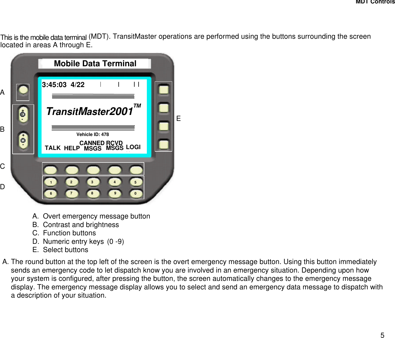
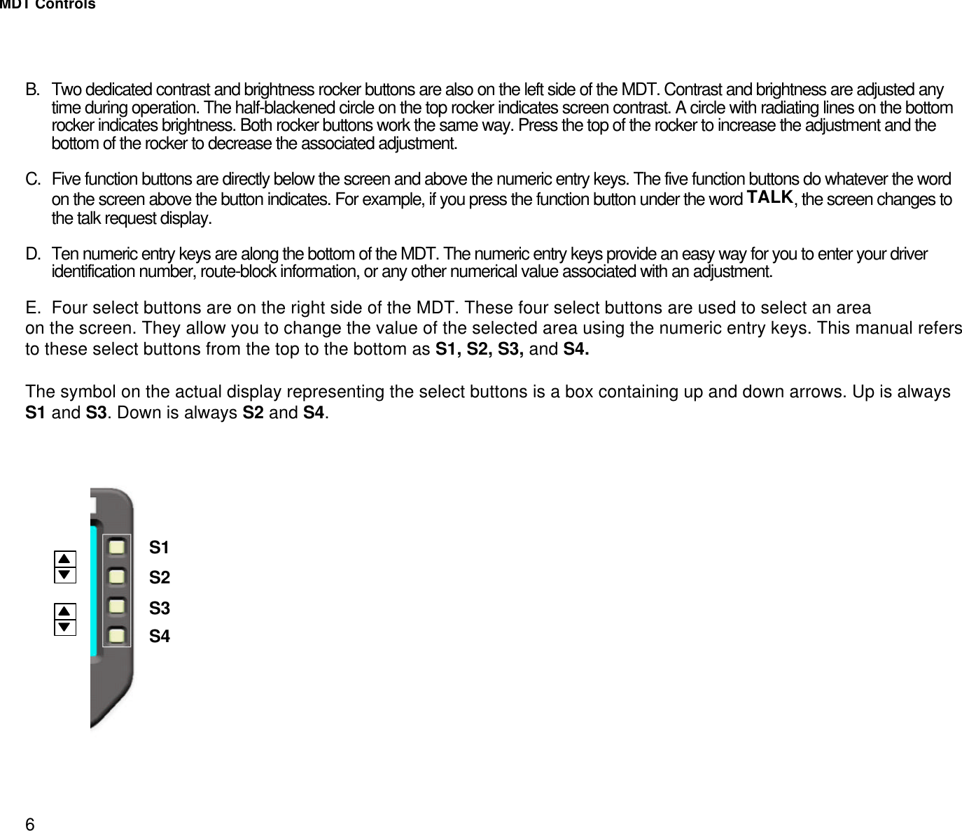
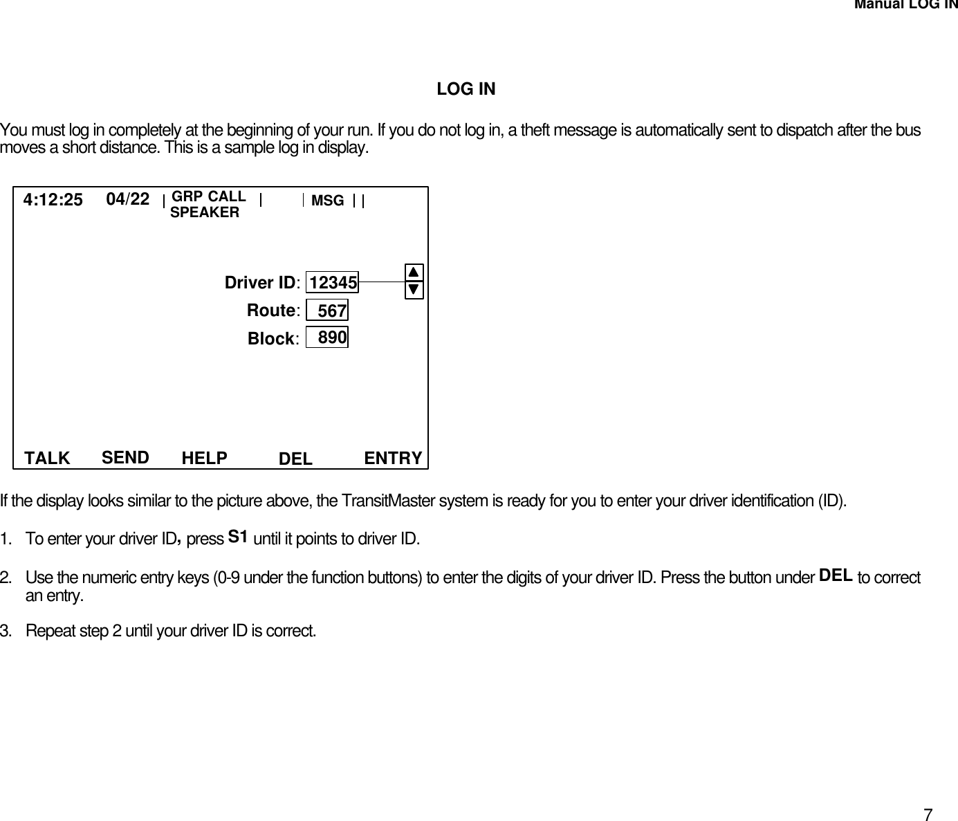
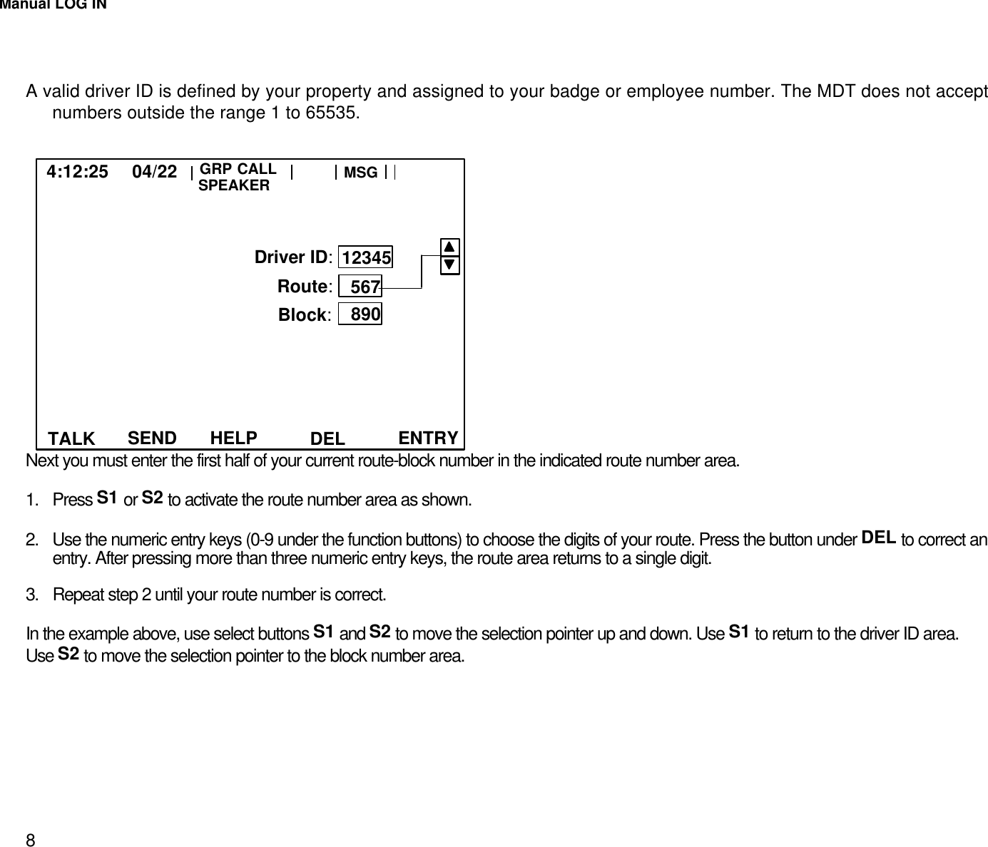
RVLU User Manual
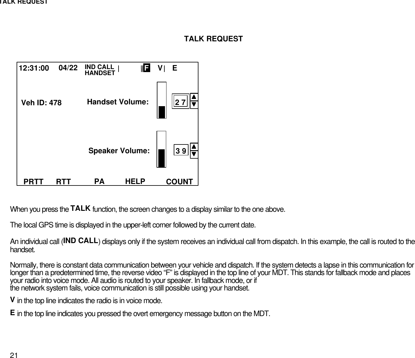
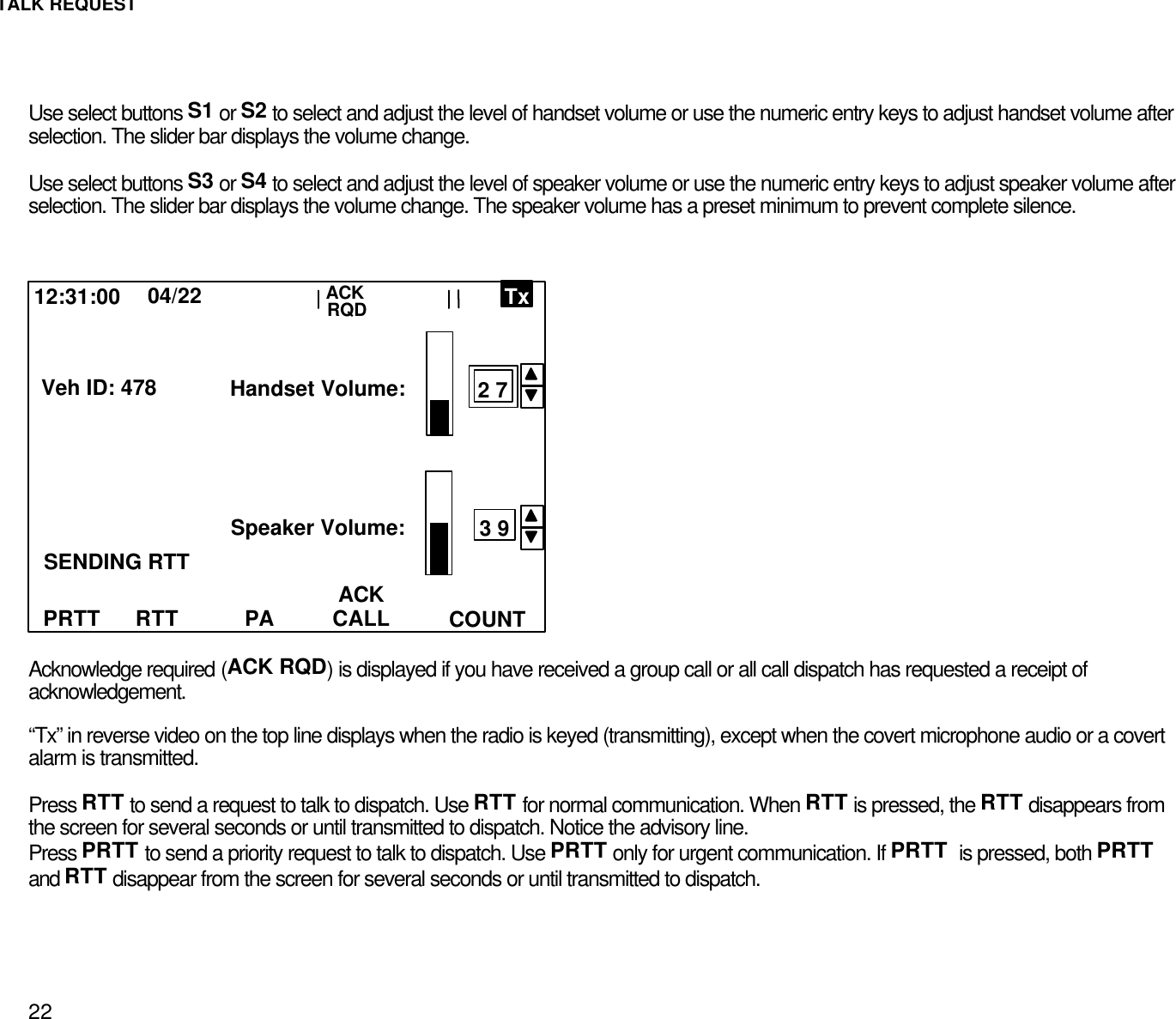
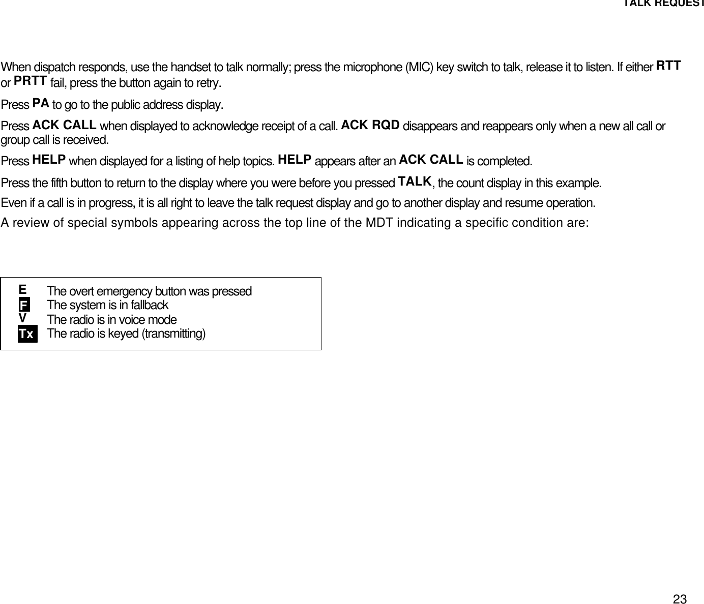
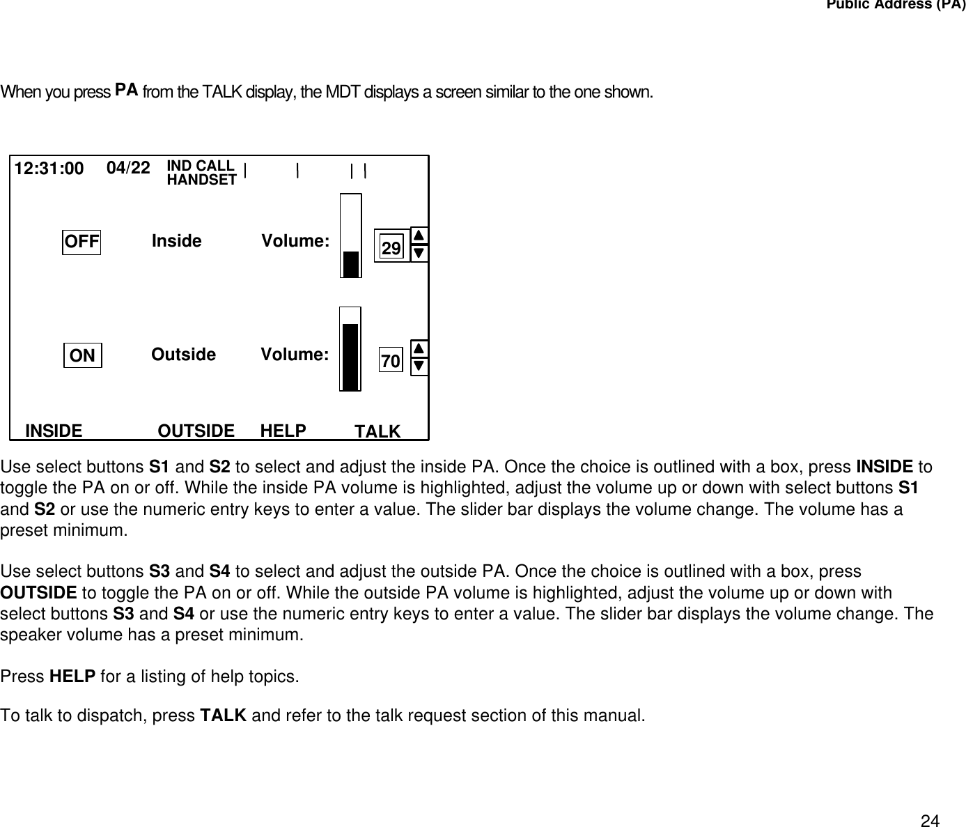
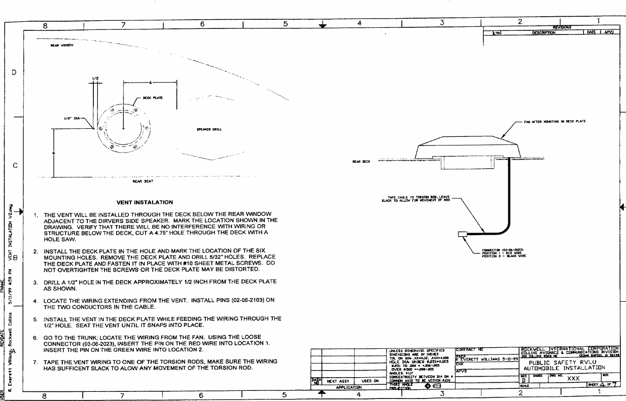
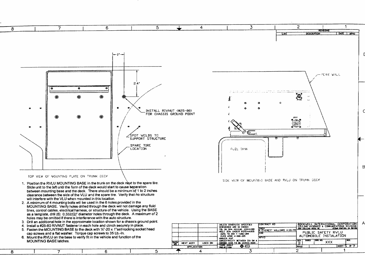
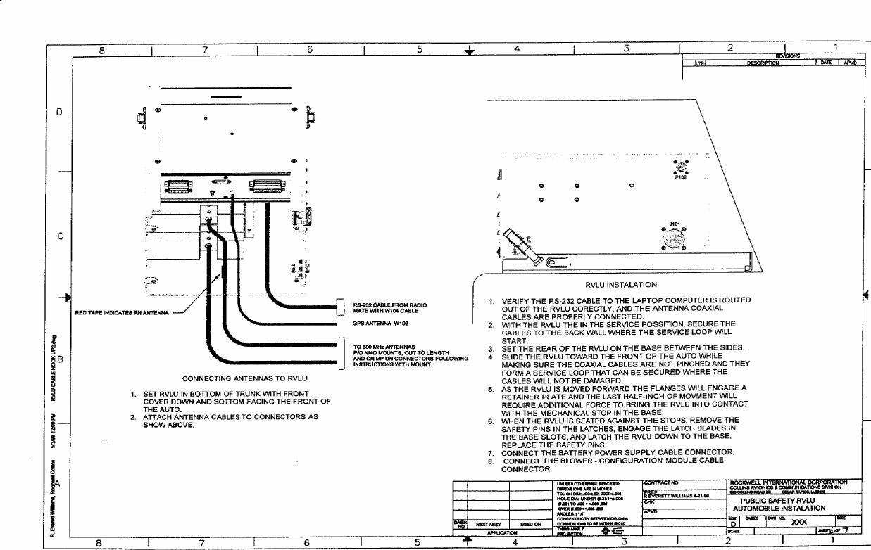
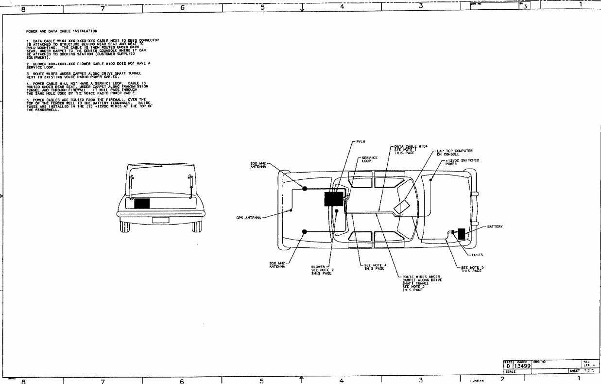
Exhibit A Instruction and Installation Manuals
Navigation menu
Upload a User Manual
Namespaces
Wiki Guide
HTML
PDF
Info
Views
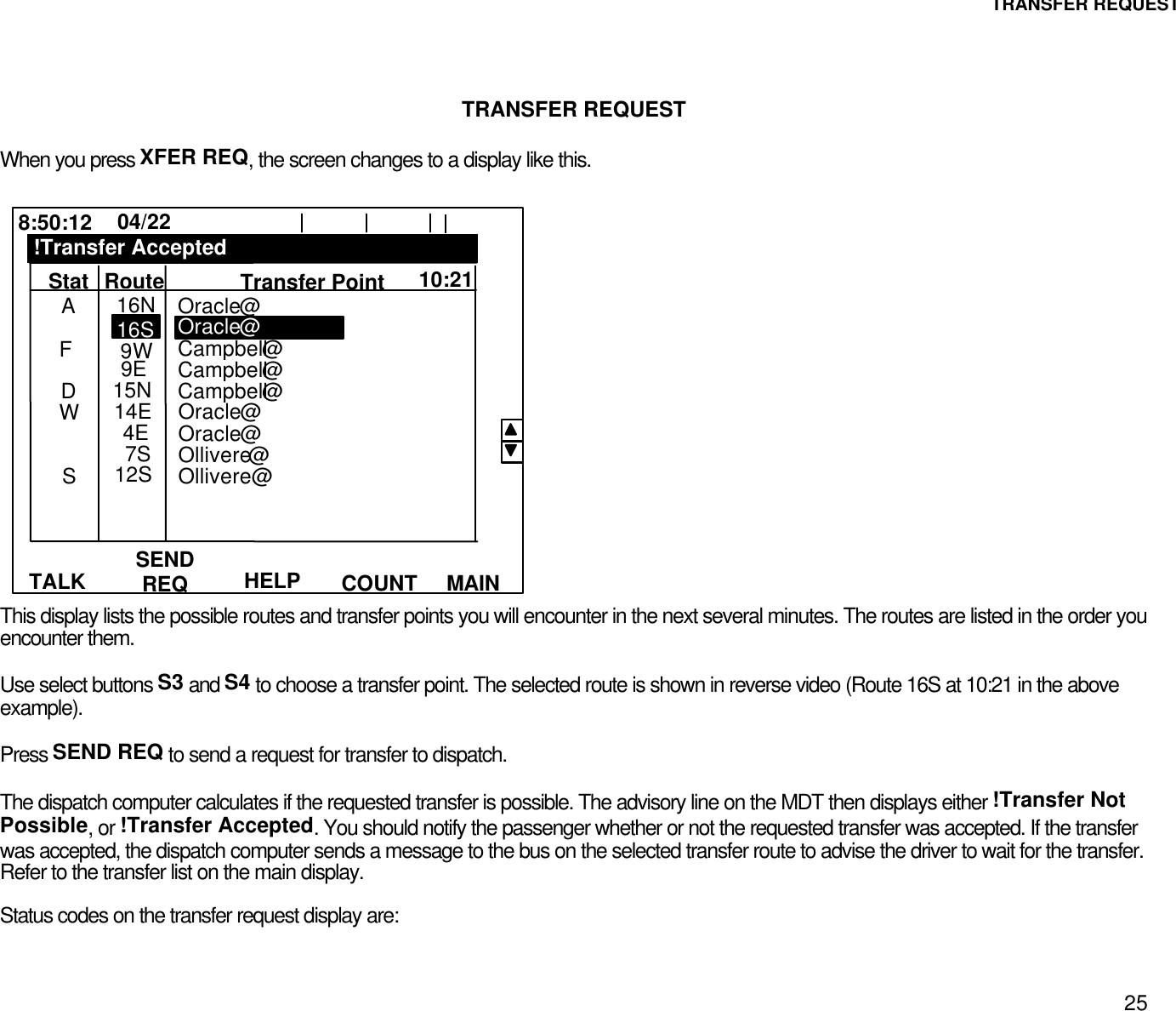
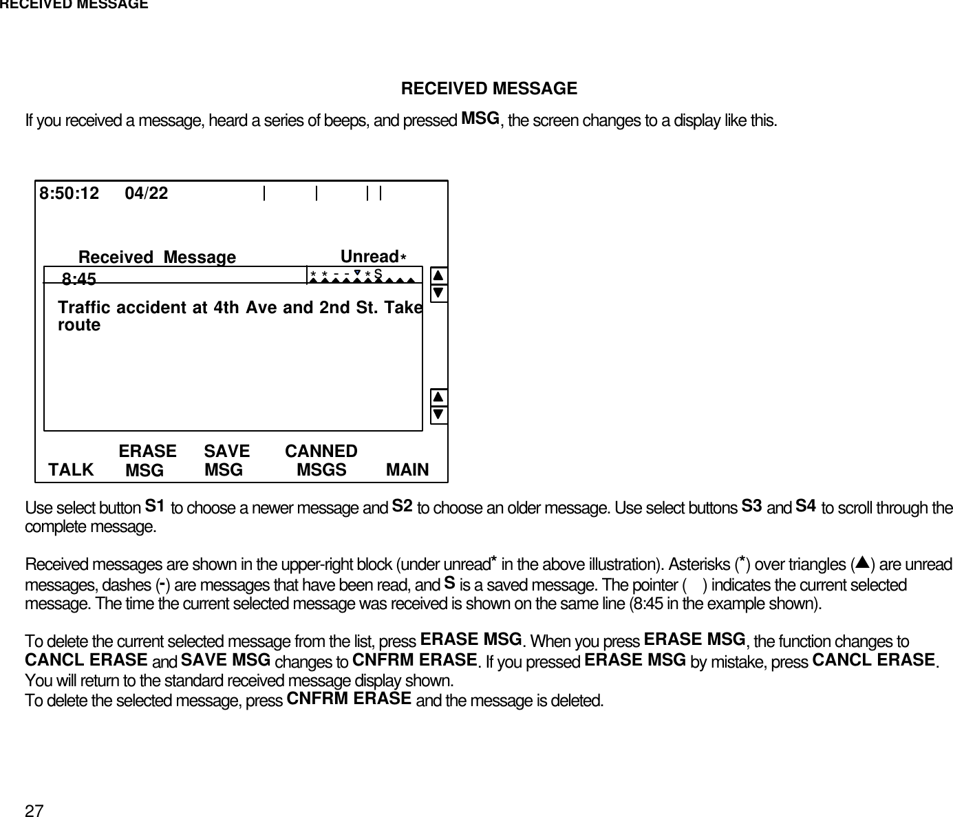
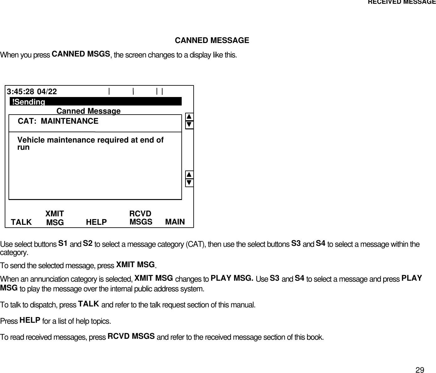
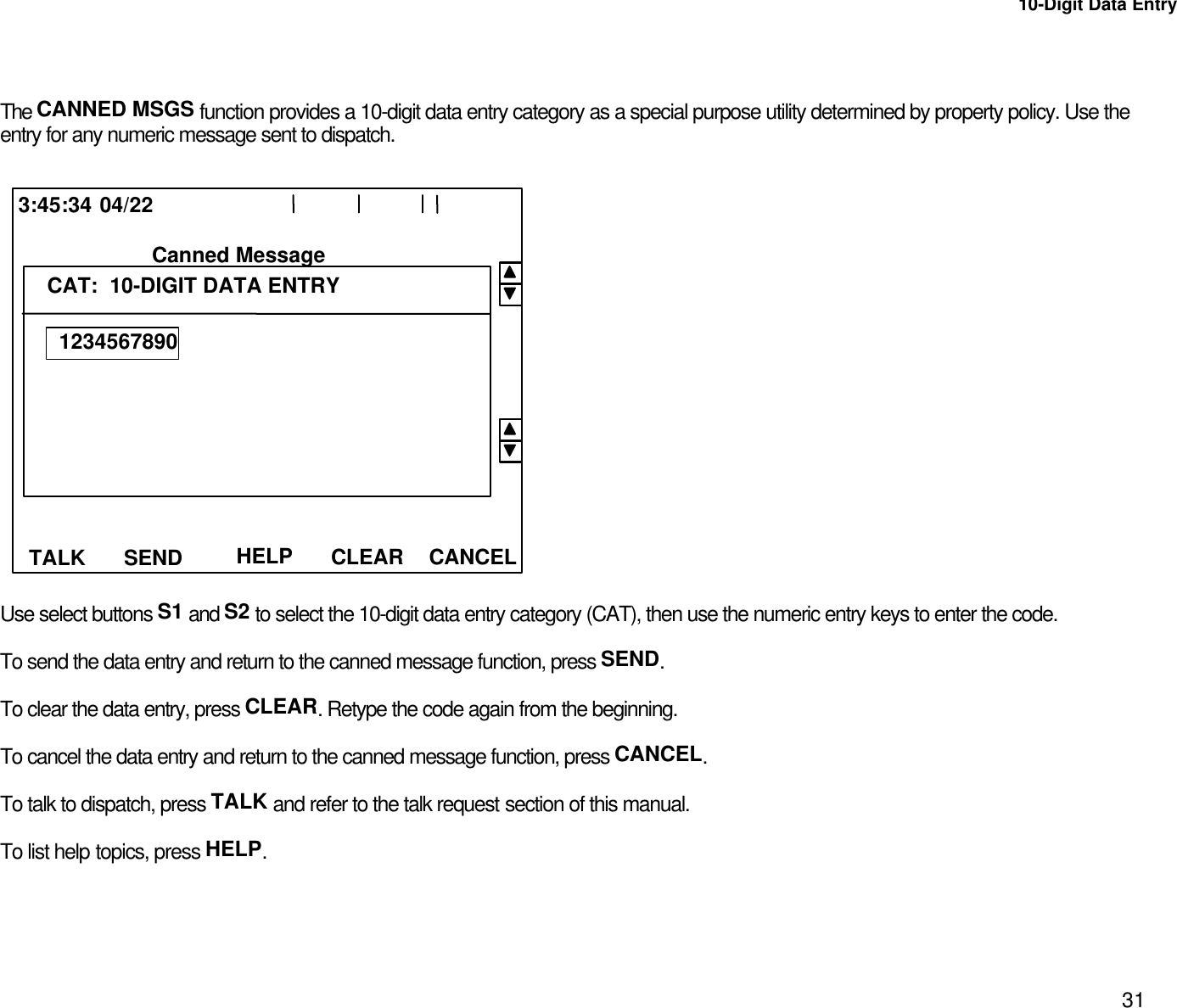
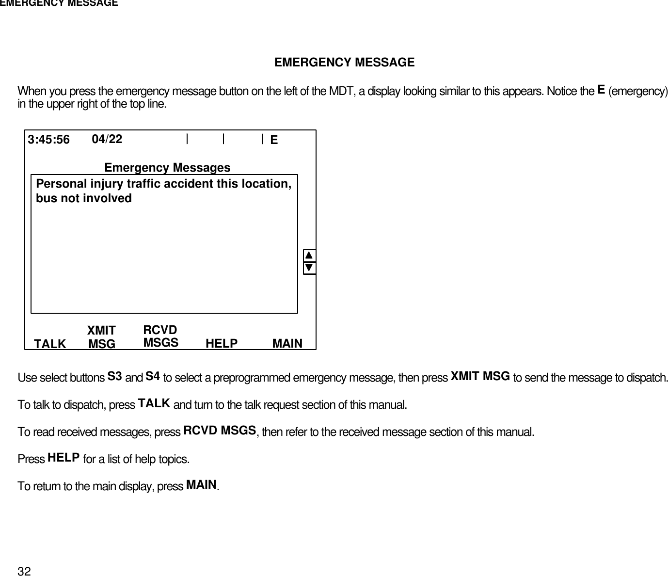
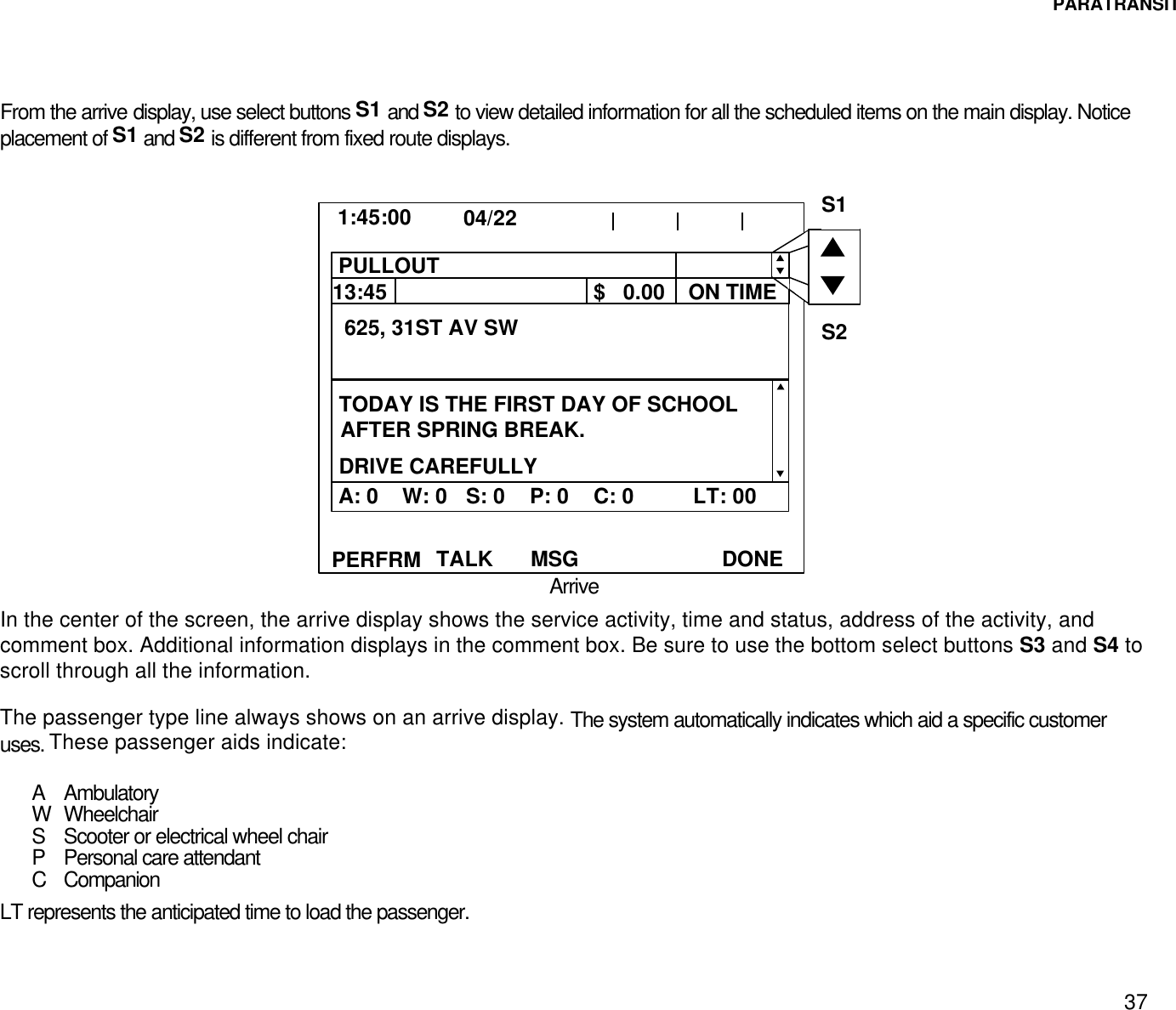
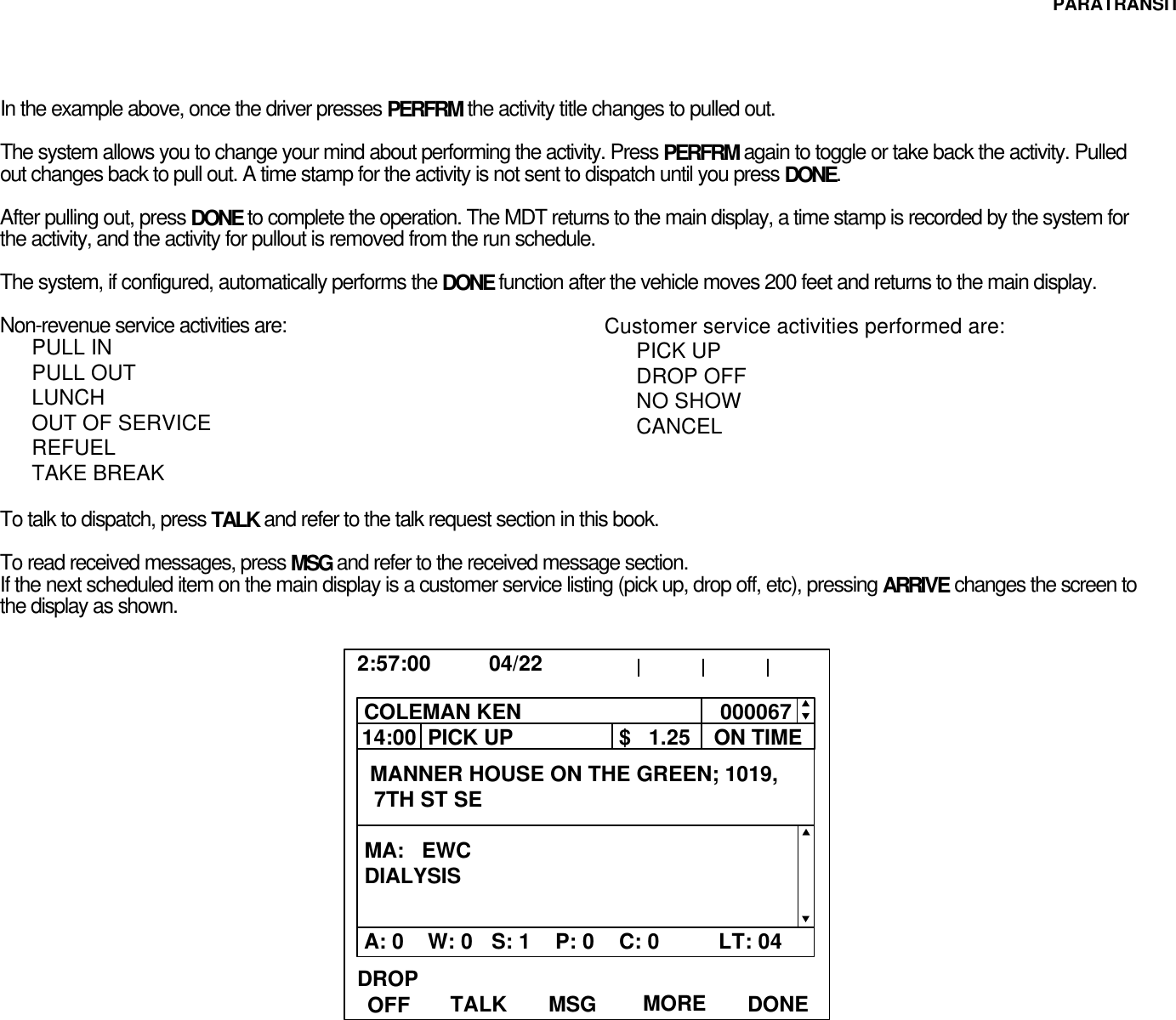
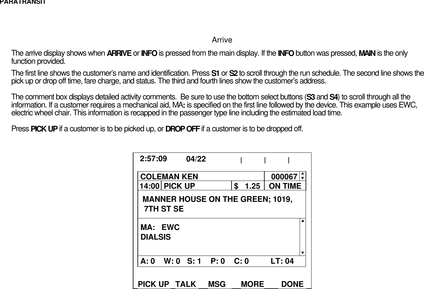
User Manual
Discussion / Help
Navigation