Rohde and Schwarz and Co KG 61020307 M3SR Series 4400 VHF/Transmitter User Manual
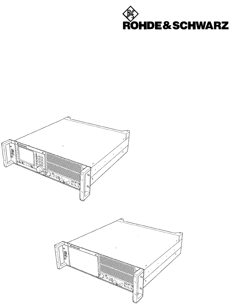
Rohde & Schwarz GmbH & Co KG M3SR Series 4400 VHF/Transmitter
Contents
- 1. Warning
- 2. Product Literature
- 3. Revised Manual
Revised Manual
Radio Communication Systems
Division
6076.0822.12.02 – 1
2SHUDWRU¶V 0DQXDO
065
9+)8+)DQG9+)8+)75$16&(,9(56
(valid for models ≥ 02)
M3SR Software Release: 8.00
XT 4410A
XU 4410A
XD 4410A
XD 4460A
XU 4410A
XT 4460A
©
Copying of this document as well as any other utilization and communication of its content are only admissible
with the permission of the originator or other authorized persons.
Any disregard will be prosecuted and is subject to restitution (UrhG, UWG, BGB). For the case a patent is is-
sued or the design is officially registered all rights are reserved.
52+'(6&+:$5=*PE+&R.*'0QFKHQ0KOGRUIVWU7HO,QW
7HOHID[,QW
3ULQWHGLQWKH)HGHUDO5HSXEOLFRI*HUPDQ\6XEMHFWWRFKDQJH'DWDZLWKRXWWROHUDQFHVRUGHURIPDJQLWXGHRQO\
6076.0822.12.02 – 2

Adressen/Addresses
FIRMENSITZ/HEADQUARTERS Phone
Fax
E-mail
Rohde & Schwarz GmbH & Co. KG
Mühldorfstraße 15 · D-81671 München
Postfach 80 14 69 · D-81614 München
+49 (89) 41 29-0
+49 89 4129-121 64
-
WERKE/PLANTS
Rohde & Schwarz Messgerätebau GmbH
Riedbachstraße 58 · D-87700 Memmingen
Postfach 1652 · D-87686 Memmingen
+49 (8331) 108-0
+49 (8331) 108-11 24
-
Rohde & Schwarz GmbH & Co. KG
Werk Teisnach
Kaikenrieder Straße 27 · D-94244 Teisnach
Postfach 1149 · D-94240 Teisnach
+49 (9923) 857-0
+49 (9923) 857-11 74
-
Rohde & Schwarz GmbH & Co. KG
Dienstleistungszentrum Köln
Graf-Zeppelin-Straße 18 · D-51147 Köln
Postfach 98 02 60 · D-51130 Köln
+49 (2203) 49-0
+49 (2203) 49 51-308
info@rsdc.rohde-schwarz.com
service@rsdc.rohde-schwarz.com
TOCHTERUNTERNEHMEN/SUBSIDIARIES
Rohde & Schwarz Vertriebs-GmbH
Mühldorfstraße 15 · D-81671 München
Postfach 80 14 69 · D-81614 München
+49 (89) 41 29-137 74
+49 (89) 41 29-137 77
-
Rohde & Schwarz International GmbH
Mühldorfstraße 15 · D-81671 München
Postfach 80 14 60 · D-81614 München
+49 (89) 41 29-129 84
+49 (89) 41 29-120 50
-
Rohde & Schwarz Engineering and Sales
GmbH
Mühldorfstraße 15 · D-81671 München
Postfach 80 14 29 · D-81614 München
+49 (89) 41 29-137 11
+49 (89) 41 29-137 23
-
R&S BICK Mobilfunk GmbH
Fritz-Hahne-Str. 7 · D-31848 Bad Münder
Postfach 2062 · D-31844 Bad Münder
+49 (5042) 998-0
+49 (5042) 998-105
-
Rohde & Schwarz FTK GmbH
Wendenschlossstraße 168, Haus 28
D-12557 Berlin
+49 (30) 658 91-122
+49 (30) 655 50-221
-
Rohde & Schwarz SIT GmbH
Agastraße 3
D-12489 Berlin
+49 (30) 658 84-0
+49 (30) 658 84-183
ADRESSEN DEUTSCHLAND/ADDRESSES
GERMANY
Rohde & Schwarz Vertriebs-GmbH
Mühldorfstraße 15 · D-81671 München
Postfach 80 14 69 · D-81614 München
+49 89 4129-133 74
+4989 4129-133 77
-
Zweigniederlassungen der Rohde &
Schwarz Vertriebs-GmbH/Branch offices of
Rohde & Schwarz Vertriebs-GmbH
Zweigniederlassung Nord, Geschäftsstelle
Berlin
Ernst-Reuter-Platz 10 · D-10587 Berlin
Postfach 100620 · D-10566 Berlin
+49 (30) 34 79 48-0
+49 (30) 34 79 48 48
-
Zweigniederlassung Büro Bonn
Josef-Wirmer-Straße 1-3 · D-53123 Bonn
Postfach 140264 · D-53057 Bonn
+49 (228) 918 90-0
+49 (228) 25 50 87
-
Zweigniederlassung Nord, Geschäftsstelle
Hamburg
Steilshooper Alle 47 · D-22309 Hamburg
Postfach 60 22 40 · D-22232 Hamburg
+49 (40) 63 29 00-0
+49 (40) 630 78 70
-
Zweigniederlassung Mitte, Geschäftsstelle
Köln
Niederkasseler Straße 33 · D-51147 Köln
Postfach 900 149 · D-51111 Köln
+49 (2203) 807-0
+49 (2203) 807-650
-
Zweigniederlassung Süd, Geschäftsstelle
München
Mühldorfstraße 15 · D-81671 München
Postfach 80 14 69 · D-81614 München
+49 (89) 41 86 95-0
+49 (89) 40 47 64
-
Zweigniederlassung Süd, Geschäftsstelle
Nürnberg
Donaustraße 36
D-90451 Nürnberg
+49 (911) 642 03-0
+49 (911) 642 03-33
-
Zweigniederlassung Mitte, Geschäftsstelle
Neu-Isenburg
Siemensstraße 20
D-63263 Neu-Isenburg
+49 (6102) 20 07-0
+49 (6102) 20 07 12
-
ADRESSEN WELTWEIT/ADDRESSES
WORLDWIDE
siehe / see AustriaAlbania
ROHDE & SCHWARZ
Bureau d'Alger
5B Place de Laperrine
16035 Hydra-Alger
+213 (21) 48 20 18
+213 (21) 69 46 08
Algeria
PRECISION ELECTRONICA S.R.L.
Av. Pde Julio A. Roca 710 - 6° Piso
(C1067ABP) Buenos Aires
+541 (14) 331 41 99
+541 (14) 334 51 11
alberto_lombardi@prec-elec.com.ar
Argentina
ROHDE & SCHWARZ (AUSTRALIA) Pty. Ltd.
Sales Support
Unit 6
2-8 South Street
Rydalmere, N.S.W. 2116
+61 (2) 88 45 41 00
+61 (2) 96 38 39 88
lyndell.james@rsaus.rohde-
schwarz.com
Australia
ROHDE & SCHWARZ-ÖSTERREICH
Ges.m.b.H.
Am Euro Platz 3
Gebäude B
1120 Wien
+43 (1) 602 61 41-0
+43 (1) 602 61 41-14
office@rsoe.rohde-schwarz.com
Austria
ROHDE & SCHWARZ Azerbaijan
Liaison Office Baku
ISR Plaza
340 Nizami Str.
370000 Baku
+994 (12) 93 31 38
+994 (12) 93 03 14
RS-Azerbaijan@RUS.Rohde-
Schwarz.com
Azerbaijan
siehe / see DenmarkBaltic
Countries
BIL Consortium Ltd.
Corporation Office
House No: 95/A, Block - 'F'
Road No. 4, Banani
Dhaka-1213
+880 (2) 881 06 53
+880 (2) 882 82 91
Bangladesh
ROHDE & SCHWARZ BELGIUM N.V.
Excelsiorlaan 31 Bus 1
1930 Zaventem
+32 (2) 721 50 02
+32 (2) 725 09 36
info@rsb.rohde-schwarz.com
Belgium
ROHDE & SCHWARZ DO BRASIL LTDA.
Av. Alfredo Egidio de Souza Aranha n° 177,
1° andar - Santo Amaro
04726-170 Sao Paulo - SP
+55 (11) 56 44 86 11 (general)
+55 (11) 56 44 86 25 (sales)
+55 (11) 56 44 86 36
sales-brazil@rsdb.rohde-
schwarz.com
Brasil
GKL Equipment PTE. Ltd.
Jurong Point Post Office
P.O.Box 141
Singapore 916405
+65 (6) 276 06 26
+65 (6) 276 06 29
gkleqpt@singnet.com.sg
Brunei
ROHDE & SCHWARZ ÖSTERREICH
Representation Office Bulgaria
39, Fridtjof Nansen Blvd.
1000 Sofia
+359 (2) 963 43 34
+359 (2) 963 21 97
rohdebg@rsoe.rohde-schwarz.com
Bulgaria
siehe / see SloveniaBosnia-
Herzegovina

Adressen/Addresses
ROHDE & SCHWARZ CANADA Inc.
555 March Rd.
Kanata, Ontario K2K 2M5
+1 (613) 592 80 00
+1 (613) 592 80 09
cgirwarnauth@rscanada.ca
Canada
TEKTRONIX CANADA Inc.
Test and Measurement
4929 Place Olivia
Saint-Laurent, Pq
Montreal H4R 2V6
+1 (514) 331 43 34
+1 (514) 331 59 91
Canada
DYMEQ Ltda.
Av. Larrain 6666
Santiago
+56 (2) 339 20 00
+56 (2) 339 20 10
dnussbaum@dymeq.com
Chile
ROHDE & SCHWARZ China Ltd.
Representative Office Shanghai
Central Plaza
227 Huangpi North Road
RM 807/809
Shanghai 200003
+86 (21) 63 75 00 18
+86 (21) 63 75 91 70
China
ROHDE & SCHWARZ China Ltd.
Representative Office Beijing
Room 602, Parkview Center
2 Jiangtai Road
Chao Yang District
Beijing 100016
+86 (10) 64 31 28 28
+86 (10) 64 37 98 88
info.rschina@rsbp.rohde-
schwarz.com
China
ROHDE & SCHWARZ China Ltd.
Representative Office Guangzhou
Room 2903, Metro Plaza
183 Tianhe North Road
Guangzhou 510075
+86 (20) 87 55 47 58
+86 (20) 87 55 47 59
China
ROHDE & SCHWARZ China Ltd.
Representative Office Chengdu
Unit G, 28/F, First City Plaza
308 Shuncheng Avenue
Chengdu 610017
+86 (28) 86 52 76 05 to 09
+86 (28) 86 52 76 10
rsbpc@mail.sc.cninfo.net
China
ROHDE & SCHWARZ China Ltd.
Unit 3115
31/F Entertainment Building
30 Queen's Road Central
Hongkong
+85 (2) 21 68 06 70
+85 (2) 21 68 08 99
China
ROHDE & SCHWARZ China Ltd.
Representative Office Xi'an
Room 10125, Jianguo Hotel Xi'an
No. 2, Huzhu Road
Xi'an 710048
+86 (29) 321 82 33
+86 (29) 329 60 15
sherry.yu@rsbp.rohde-schwarz.com
China
Shanghai ROHDE & SCHWARZ
Communication Technology Co.Ltd.
Central Plaza, Unit 809
227 Huangpi North Road
Shanghai 200003
China
Beijing ROHDE & SCHWARZ Communication
Technology Co.Ltd.
Room 106, Parkview Centre
No. 2, Jiangtai Road
Chao Yang District
Beijing 100016
+86 (10) 64 38 80 80
+86 (10) 64 38 97 06
China
siehe / see SloveniaCroatia
HINIS TELECAST LTD.
Agiou Thoma 18
Kiti
Larnaca 7550
+357 (24) 42 51 78
+357 (24) 42 46 21
hinis@logos.cy.net
Cyprus
ROHDE & SCHWARZ - Praha s.r.o.
Hadovka Office Park
Evropská 33c
16000 Praha 6
+420 (2) 24 31 12 32
+420 (2) 24 31 70 43
office@rscz.rohde-schwarz.com
Czech Republic
ROHDE & SCHWARZ DANMARK A/S
Ejby Industrivej 40
2600 Glostrup
+45 (43) 43 66 99
+45 (43) 43 77 44
Denmark
REPRESENTACIONES MANFRED
WEINZIERL
Vía Láctea No. 4 y Via Sta. Inés
P.O.Box 17-22-20309
1722 Cumbayá-Quito
+593 (22) 89 65 97
+593 (22) 89 65 97
mweinzierl@accessinter.net
Ecuador
U.A.S. Universal Advanced Systems
31 Manshiet El-Bakry Street
Heliopolis
11341 Cairo
+20 (2) 455 67 44
+20 (2) 256 17 40
an_uas@link.net
Egypt
siehe / see MexicoEl Salvador
ROHDE & SCHWARZ DANMARK A/S
Estonian Branch Office
Narva mnt. 13
10151 Tallinn
+372 (6) 14 31 23
+372 (6) 14 31 21
margo.fingling@rsdk.rohde-
schwarz.com
Estonia
Orbis Oy
P.O.Box 15
00421 Helsinski 42
+358 (9) 47 88 30
+358 (9) 53 16 04
info@orbis.fi
Finland
ROHDE & SCHWARZ FRANCE
Immeuble "Le Newton"
9-11, rue Jeanne Braconnier
92366 Meudon La Forêt Cédex
+33 (1) 41 36 10 00
+33 (1) 41 36 11 73
France
Niederlassung/Subsidiary Rennes
37 Rue du Bignon
Bât. A
F-35510 Cesson Sevigne
+33 (0) 299 51 97 00
+33 (0) 299 51 98 77
-
France
Niederlassung/Subsidiary Toulouse
Technoparc 3
B.P. 501
F-31674 Labège Cédex
+33 (0) 561 39 10 69
+33 (0) 561 39 99 10
-
France
Aix-en-Provence +33 (0) 494 07 39 94
+33 (0) 494 07 55 11
-
France
Office Lyon +33 (0) 478 29 88 10
+33 (0) 478 79 18 57
France
Office Nancy +33 (0) 383 54 51 29
+33 (0) 383 54 82 09
France
KOP Engineering Ltd.
P.O. Box 11012
3rd Floor Akai House, Osu
Accra North
+233 (21) 77 89 13
+233 (21) 701 06 20
Ghana
MERCURY S.A.
6, Loukianou Str.
10675 Athens
+302 (10) 722 92 13
+302 (10) 721 51 98
mercury@hol.gr
Greece
siehe / see Mexico Guatemala
siehe / see Mexico Honduras
Electronic Scientific Engineering
36/F Dorset House, Taikoo Place
979 King's Road
Quarry Bay
Hong Kong
+852 (25) 07 03 33
+852 (25) 07 09 25
stephenchau@ese.com.hk
Hongkong
ROHDE & SCHWARZ
Budapesti Iroda
Váci út 169
1138 Budapest
+36 (1) 412 44 60
+36 (1) 412 44 61
rohdehu@rsoe.rohde-schwarz.com
Hungary
siehe / see DenmarkIceland

Adressen/Addresses
ROHDE & SCHWARZ India Pvt. Ltd.
Bangalore Office
No. 24, Service Road, Domlur
2nd Stage Extension
Bangalore - 560 071
+91 (80) 535 23 62
+91 (80) 535 03 61
rsindiab@rsnl.net
India
ROHDE & SCHWARZ India Pvt. Ltd.
Hyderabad Office
302 & 303, Millenium Centre
6-3-1099/1100, Somajiguda
Hyderabad - 500 016
+91 (40) 23 32 24 16
+91 (40) 23 32 27 32
rsindiah@nd2.dot.net.in
India
ROHDE & SCHWARZ India Pvt. Ltd.
244, Okhla Industrial Estate, Phase-III
New Delhi 110020
+91 (11) 26 32 63 81
+91 (11) 26 32 63 73
sales@rsindia.rohde-schwarz
services@rsindia.rohde-schwarz.com
India
ROHDE & SCHWARZ India Pvt. Ltd.
RS India Mumbai Office
B-603, Remi Bizcourt, Shah Industrial
Estate, Off Veera Desai Road
Mumbai - 400 058
+91 (22) 26 30 18 10
+91 (22) 26 32 63 73
rsindiam@rsnl.net
India
PT ROHDE & SCHWARZ Indonesia
Graha Paramita 5th Floor
Jln. Denpasar Raya Blok D-2
Jakarta 12940
+62 (21) 252 36 08
+62 (21) 252 36 07
sales@rsbj.rohde-schwarz.com
services@rsbj.rohde-schwarz.com
Indonesia
ROHDE & SCHWARZ IRAN
Groundfloor No. 1, 14th Street
Khaled Eslamboli (Vozara) Ave.
15117 Tehran
+98 (21) 872 42 96
+98 (21) 871 90 12
rs-tehran@neda.net
Iran
siehe / see United KingdomIreland
EASTRONICS LTD.
Messtechnik / T&M Equipment
11 Rozanis St.
P.O.Box 39300
Tel Aviv 61392
+972 (3) 645 87 77
+972 (3) 645 86 66
david_hasky@easx.co.il
Israel
J.M. Moss (Engineering) Ltd.
Kommunikationstechnik/ Communications
Equipment
9 Oded Street
P.O.Box 967
52109 Ramat Gan
+972 (3) 631 20 57
+972 (3) 631 40 58
jmmoss@zahav.net.il
Israel
ROHDE & SCHWARZ ITALIA S.p.a.
Centro Direzionale Lombardo
Via Roma 108
20060 Cassina de Pecchi (MI)
+39 (02) 95 70 42 03
+39 (02) 95 30 27 72
ornella.crippa@rsi.rohde-
schwarz.com
Italy
ROHDE & SCHWARZ ITALIA S.p.a.
Via Tiburtina 1182
00156 Roma
+39 (06) 41 59 82 18
+39 (06) 41 59 82 70
Italy
ADVANTEST Corporation
RS Sales Department
1-32-1, Asahi-cho
Nerima-ku
Tokyo 179-0071
+81 (3) 39 30 41 90
+81 (3) 39 30 41 86
RSSales@advantest.co.jp
Japan
Jordan Crown Engineering & Trading Co.
Jabal Amman, Second Circle
Youssef Ezzideen Street
P.O.Box 830414
Amman, 11183
+962 (6) 462 17 29
+962 (6) 465 96 72
jocrown@go.com.jo
Jordan
ROHDE & SCHWARZ Kazakhstan
Representative Office Almaty
Pl. Respubliki 15
480013 Almaty
+7 (32) 72 63 55 55
+7 (32) 72 63 46 33
RS-Kazakhstan@RUS-Rohde-
Schwarz.com
Kazakhstan
Excel Enterprises Ltd
Dunga Road
P.O.Box 42 788
Nairobi
+254 (2) 55 80 88
+254 (2) 54 46 79
Kenya
ROHDE & SCHWARZ Korea Ltd.
83-29 Nonhyun-Dong, Kangnam-Ku
Seoul 135-010
+82 (2) 514 45 46
+82 (2) 514 45 49
sales@rskor.rohde-schwarz.com
service@rskor.rohde-schwarz.com
Korea
Group Five Trading & Contracting Co.
Mezanine Floor
Al-Bana Towers
Ahmad Al Jaber Street
Sharq
+965 (244) 91 72/73/74
+965 (244) 95 28
jk_agarwal@yahoo.com
Kuwait
ROHDE & SCHWARZ DANMARK A/S
Latvian Branch Office
Merkela iela 21-301
1050 Riga
+371 (7) 50 23 55
+371 (7) 50 23 60
rsdk@rsdk.rohde-schwarz.com
Latvia
ROHDE & SCHWARZ Liaison Office
c/o Haji Abdullah Alireza Co. Ltd.
P.O.Box 361
Riyadh 11411
+966 (1) 465 64 28 Ext. 303
+966 (1) 465 64 28 Ext. 229
chris.porzky@rsd.rohde-schwarz.com
Lebanon
NetcomLebanon
siehe / see SwitzerlandLiechtenstein
ROHDE & SCHWARZ DANMARK A/S
Lithuanian Office
Lukiskiu 5-228
2600 Vilnius
+370 (5) 239 50 10
+370 (5) 239 50 11
Lithuania
siehe / see BelgiumLuxembourg
siehe / see SloveniaMacedonia
DAGANG TEKNIK SDN. BHD.
No. 9, Jalan SS 4D/2
Selangor Darul Ehsan
47301 Petaling Jaya
+60 (3) 27 03 55 68
+60 (3) 27 03 34 39
mey.nara@danik.com.my
Malaysia
ITEC International Technology Ltd
B'Kara Road
San Gwann SGN 08
+356 (21) 37 43 00 or 37 43 29
+356 (21) 37 43 53
sales@itec.com.mt
Malta
Rohde & Schwarz de Mexico (RSMX)
S. de R.L. de C.V.
German Centre Oficina 4-2-2
Av. Santa Fé 170
Col. Lomas de Santa Fé
01210 Mexico D.F.
+52 (55) 85 03 99 13
+52 (55) 85 03 99 16
latinoamerica@rsd.rohde-
schwarz.com
Mexico
Rohde & Schwarz de Mexico (RSMX)
Av. Prol. Americas No. 1600, 2° Piso
Col. Country Club
Guadalajara, Jal.
Mexico CP, 44610
+52 (33) 36 78 91 70
+52 (33) 36 78 92 00
Mexico
siehe / see RomaniaMoldavia
ROHDE & SCHWARZ NEDERLAND B.V.
Perkinsbaan 1
3439 ND Nieuwegein
+31 (30) 600 17 00
+31 (30) 600 17 99
info@rsn.rohde-schwarz.com
Netherlands
Nichecom
1 Lincoln Ave.
Tawa, Wellington
+64 (4) 232 32 33
+64 (4) 232 32 30
rob@nichecom.co.nz
New Zealand
siehe / see MexicoNicaragua
Ferrostaal Abuja
Plot 3323, Barada Close
P.O.Box 8513, Wuse
Off Amazon Street
Maitama, Abuja
+234 (9) 413 52 51
+234 (9) 413 52 50
fsabuja@rosecom.net
Nigeria

Adressen/Addresses
ROHDE & SCHWARZ NORGE AS
Enebakkveien 302 B
1188 Oslo
+47 (23) 38 66 00
+47 (23) 38 66 01
Norway
Mustafa Sultan Science & Industry Co.LLC.
For Test & Measurement ONLY
Way No. 3503
Building No. 241
Postal Code 112
Al Khuwair, Muscat
+968 636 000
+968 607 066
m-aziz@mustafasultan.com
Oman
Siemens Pakistan
23, West Jinnah Avenue
Islamabad
+92 (51) 227 22 00
+92 (51) 227 54 98
reza.bokhary@siemens.com.pk
Pakistan
siehe / see Mexico Panama
siehe / see AustraliaPapua-New
Guinea
MARCOM INDUSTRIAL EQUIPMENT, Inc.
6-L Vernida I Condominium
120 Amorsolo St.
Legaspi Village
Makati City/ Philippines 1229
+63 (2) 813 29 31
+63 (2) 810 58 07
marcom@i-next.net
Philippines
ROHDE & SCHWARZ Österreich SP.z o.o.
Przedstawicielstwo w Polsce
ul. Stawki 2, Pietro 28
00-193 Warszawa
+48 (22) 860 64 94
+48 (22) 860 64 99
rohdepl@rsoe.rohde-schwarz.com
Poland
Rohde & Schwarz Portugal, Lda.
Alameda Antonio Sergio, n° 7
R/C, Sala A
2795-023 Linda-a-Velha
+351 (21) 415 57 00
+351 (21) 415 57 10
telerus@mail.telepac.pt
Portugal
ROHDE & SCHWARZ
Representation Office Bucharest
Str. Uranus 98
Sc. 2, Et. 5, Ap. 36
76102 Bucuresti, Sector 5
+40 (21) 410 68 46
+40 (21) 411 20 13
rohdero@rsoe.rohde-schwarz.com
Romania
ROHDE & SCHWARZ
Representative Office Moscow
119180, Yakimanskaya nab., 2
Moscow
+7 (095) 745 88 50 to 53
+7 (095) 745 88 54
rs-russia@rsru.rohde-schwarz.com
Russian
Federation
Mr. Chris Porzky
ROHDE & SCHWARZ International GmbH
c/o Haji Abdullah Alireza Co. Ltd.
P.O.Box 361
Riyadh 11411
+966 (1) 465 64 28 Ext. 303
+966 (1) 465 6428 Ext. 229
chris.porzky@rsd.rohde-schwarz.com
Saudi Arabia
GENTECSaudi Arabia
Representative Office Belgrade
Tose Jovanovica 7
11030 Beograd
+381 (11) 305 50 25
+381 (11) 305 50 24
Serbia-
Montenegro
Specialne systemy a software, a.s.
Svrcia ul.
841 04 Bratislava
+421 (2) 65 42 24 88
+421 (2) 65 42 07 68
stefan.lozek@special.sk
Slovak
Republic
ROHDE & SCHWARZ
Representation Ljubljana
Tbilisijska 89
1000 Ljubljana
+386 (1) 423 46 51
+386 (1) 423 46 11
rohdesi@rsoe.rohde-schwarz.com
Slovenia
Protea Data Systems (Pty.) Ltd.
Communications and Measurement Division
Private Bag X19
Bramley 2018
+27 (11) 719 57 00
+27 (11) 786 58 91
unicm@protea.co.za
South Africa
Protea Data Systems (Pty.) Ltd.
Cape Town Branch
Unit G9, Centurion Business Park
Bosmandam Road
Milnerton
Cape Town, 7441
+27 (21) 555 36 32
+27 (21) 555 42 67
unicm@protea.co.za
South Africa
ROHDE & SCHWARZ ESPANA S.A.
Salcedo, 11
28034 Madrid
+34 (91) 334 10 70
+34 (91) 329 05 06
rses@rses-rohde-schwarz.com
Spain
LANKA AVIONICS
658/1/1, Negombo Road
Mattumagala
Ragama
+94 (1) 95 66 78
+94 (1) 95 83 11
lankavio@sltnet.lk
Sri Lanka
SolarMan Co. Ltd.
P.O.Box 11 545
North of Fraouq Cementry 6/7/9 Bldg. 16
Karthoum
+249 (11) 47 31 08
+249 (11) 47 31 38
solarman29@hotmail.com
Sudan
ROHDE & SCHWARZ SVERIGE AB
Marketing Div.
Flygfältsgatan 15
128 30 Skarpnäck
+46 (8) 605 19 00
+46 (8) 605 19 80
info@rss.se
Sweden
Roschi Rohde & Schwarz AG
Mühlestr. 7
3063 Ittigen
+41 (31) 922 15 22
+41 (31) 921 81 01
sales@roschi.rohde-schwarz.com
Switzerland
Electro Scientific Office
Baghdad Street
Dawara Clinical Lab. Bldg
P.O.Box 8162
Damascus
+963 (11) 231 59 74
+963 (11) 231 88 75
memo@hamshointl.com
Syria
Lancer Communication Co. Ltd.
for Div. 1 and 7
16F, No. 30, Pei-Ping East Road
Taipei
+886 (2) 23 91 10 02
+886 (2) 23 95 82 82
info@lancercomm.com.tw
Taiwan
System Communication Co. Ltd.
for Div. 2 and 8
16F, No. 30, Pei-Ping East Road
Taipei
+886 (2) 23 91 10 02
+886 (2) 23 95 82 82
info@lancercomm.com.tw
Taiwan
SSTL Group
P.O. Box 7512
Dunga Street Plot 343/345
Dar es Salaam
+255 (22) 276 00 37
+255 (22) 276 02 93
sstl@twiga.com
Tanzania
Schmidt Electronics (Thailand) Ltd.
63 Government Housing Bank Bldg.
Tower II, 19th floor, Rama 9 Rd.
Huaykwang, Bangkapi
Bangkok 10320
+66 (2) 643 13 30 to 39
+66 (2) 643 13 40
kamthoninthuyot@schmidtthailand.c
om
Thailand
TPP Operation Co., Ltd.
41/5 Mooban Tarinee
Boromrajchonnee Road
Talingchan, Bangkok 10170
+66 (2) 880 93 47
+66 (2) 880 93 47
thipsukon@tpp-operation.com
Thailand
siehe / see MexicoTrinidad
&Tobago
TELETEK
71, Rue Alain Savary
Residence Alain Savary (C64)
1003 Tunis
Tunisia
ROHDE & SCHWARZ International GmbH
Liaison Office Istanbul
Bagdad Cad. 191/3, Arda Apt. B-Blok
81030 Selamicesme-Istanbul
+90 (216) 385 19 17
+90 (216) 385 19 18
rsturk@superonline.com
Turkey
ROHDE & SCHWARZ
Representative Office Kiev
4, Patris Loumoumba ul
01042 Kiev
+38 (044) 268 60 55
+38 (044) 268 83 64
rohdeukr@rsoe.rohde-schwarz.com
Ukraine
ROHDE & SCHWARZ International GmbH
Liaison Office Abu Dhabi
P.O. Box 31156
+971 (2) 633 56 70
+971 (2) 633 56 71
United Arab
Emirates
Abu Dhabi
michael.rogler@rsd.rohde-
schwarz.com

Adressen/Addresses
ROHDE & SCHWARZ Bick Mobile
Communication
P.O.Box 17466
Dubai
+971 (4) 883 71 35
+971 (4) 883 71 36
www.rsbick.de
United Arab
Emirates
ROHDE & SCHWARZ Emirates L.L.C.
Ahmed Al Nasri Building, Mezzanine Floor,
P.O.Box 31156
Off old Airport Road
Behind new GEMACO Furniture
Abu Dhabi
+971 (2) 631 20 40
+971 (2) 631 30 40
rsuaeam@emirates.net.ae
United Arab
Emirates
ROHDE & SCHWARZ UK Ltd.
Ancells Business Park
Fleet
Hampshire
GU 51 2UZ England
+44 (1252) 81 88 88 (sales)
+44 (1252) 81 88 18 (service)
+44 (1252) 81 14 47
sales@rsuk.rohde-schwarz.com
United
Kingdom
AEROMARINE S.A.
Cerro Largo 1497
11200 Montevideo
+598 (2) 400 39 62
+598 (2) 401 85 97
mjn@aeromarine.com.uy
Uruguay
ROHDE & SCHWARZ, Inc.
Broadcast & Comm. Equipment
(US Headquarters)
7150-K Riverwood Drive
Columbia, MD 21046
+1 (410) 910 78 00
+1 (410) 910 78 01
rsatv@rsa.rohde-schwarz.com
rsacomms@rsa.rohde-schwarz.com
USA
Rohde & Schwarz Inc.
Marketing & Support Center / T&M
Equipment
2540 SW Alan Blumlein Way
M/S 58-925
Beaverton, OR 97077-0001
+1 (503) 627 26 84
+1 (503) 627 25 65
info@rsa.rohde-schwarz.com
USA
Rohde & Schwarz Inc.
Systems & EMI Products
8080 Tristar Drive
Suite 120
Irving, Texas 75063
+1 (469) 713 53 00
+1 (469) 713 53 01
info@rsa.rohde-schwarz.com
USA
EQUILAB TELECOM C.A.
Centro Seguros La Paz
Piso 6, Local E-61
Ava. Francisco de Miranda
Boleita, Caracas 1070
+58 (2) 12 34 46 26
+58 (2) 122 39 52 05
r_ramirez@equilabtelecom.com
Venezuela
REPRESENTACIONES BOPIC S.A.
Calle C-4
Qta. San Jose
Urb. Caurimare
Caracas 1061
+58 (2) 129 85 21 29
+58 (2) 129 85 39 94
incotr@cantv.net
Venezuela
Schmidt Vietnam Co., (H.K.) Ltd.,
Representative Office in Hanoi
Intern. Technology Centre
8/F, HITC Building
239 Xuan Thuy Road
Cau Giay, Tu Liem
Hanoi
+84 (4) 834 61 86
+84 (4) 834 61 88
svnhn@schmidtgroup.com
Vietnam
siehe / see MexicoWest Indies
GEDIS GmbH
Sophienblatt 100
Postfach 22 01
24021 Kiel
+49 (431) 600 51-0
+49 (431) 600 51-11
sales@gedis-online.de

Safety Instructions
095.1000 Sheet 17
This unit has been designed and tested in accordance with the EC Certificate of Conformity and has left the
manufacturer’s plant in a condition fully complying with safety standards.
To maintain this condition and to ensure safe operation, the user must observe all instructions and warnings
given in this operating manual.
Safety-related symbols used on equipment and documentation from R&S:
Observe
operating
instructions
Weight
indication for
units >18 kg
PE terminal Ground
terminal
Danger!
Shock hazard
Warning!
Hot surfaces
Ground Attention!
Electrostatic
sensitive de-
vices require
special care
1. The unit may be used only in the operating con-
ditions and positions specified by the manufac-
turer. Unless otherwise agreed, the following
applies to R&S products:
IP degree of protection 2X, pollution severity 2
overvoltage category 2, only for indoor use, al-
titude max. 2000 m.
The unit may be operated only from supply net-
works fused with max. 16 A.
Unless specified otherwise in the data sheet, a
tolerance of ±10% shall apply to the nominal
voltage and of ±5% to the nominal frequency.
2. For measurements in circuits with voltages Vrms
> 30 V, suitable measures should be taken to
avoid any hazards.
(using, for example, appropriate measuring
equipment, fusing, current limiting, electrical
separation, insulation).
3. If the unit is to be permanently wired, the PE
terminal of the unit must first be connected to
the PE conductor on site before any other con-
nections are made. Installation and cabling of
the unit to be performed only by qualified techni-
cal personnel.
4. For permanently installed units without built-in
fuses, circuit breakers or similar protective de-
vices, the supply circuit must be fused such as
to provide suitable protection for the users and
equipment.
5. Prior to switching on the unit, it must be ensured
that the nominal voltage set on the unit matches
the nominal voltage of the AC supply network.
If a different voltage is to be set, the power fuse
of the unit may have to be changed accordingly.
6. Units of protection class I with disconnectible
AC supply cable and appliance connector may
be operated only from a power socket with
earthing contact and with the PE conductor con-
nected.
7. It is not permissible to interrupt the PE conduc-
tor intentionally, neither in the incoming cable
nor on the unit itself as this may cause the unit
to become electrically hazardous.
Any extension lines or multiple socket outlets
used must be checked for compliance with rele-
vant safety standards at regular intervals.
8. If the unit has no power switch for disconnection
from the AC supply, the plug of the connecting
cable is regarded as the disconnecting device.
In such cases it must be ensured that the power
plug is easily reachable and accessible at all
times (length of connecting cable approx. 2 m).
Functional or electronic switches are not suit-
able for providing disconnection from the AC
supply.
If units without power switches are integrated in
racks or systems, a disconnecting device must
be provided at system level.
9. Applicable local or national safety regulations
and rules for the prevention of accidents must
be observed in all work performed.
Prior to performing any work on the unit or
opening the unit, the latter must be discon-
nected from the supply network.
Any adjustments, replacements of parts, main-
tenance or repair may be carried out only by
authorized R&S technical personnel.
Only original parts may be used for replacing
parts relevant to safety (eg power switches,
power transformers, fuses). A safety test must
be performed after each replacement of parts
relevant to safety.
(visual inspection, PE conductor test, insulation-
resistance, leakage-current measurement, func-
tional test).
continued overleaf

Safety Instructions
095.1000 Sheet 18
10. Ensure that the connections with information
technology equipment comply with IEC950 /
EN60950.
11. Lithium batteries must not be exposed to high
temperatures or fire.
Keep batteries away from children.
If the battery is replaced improperly, there is
danger of explosion. Only replace the battery by
R&S type (see spare part list).
Lithium batteries are suitable for environmen-
tally-friendly disposal or specialized recycling.
Dispose them into appropriate containers, only.
Do not short-circuit the battery.
12. Equipment returned or sent in for repair must be
packed in the original packing or in packing with
electrostatic and mechanical protection.
13. Electrostatics via the connectors may dam-
age the equipment. For the safe handling and
operation of the equipment, appropriate
measures against electrostatics should be im-
plemented.
14. The outside of the instrument is suitably
cleaned using a soft, lint-free dustcloth. Never
use solvents such as thinners, acetone and
similar things, as they may damage the front
panel labeling or plastic parts.
15. Any additional safety instructions given in this
manual are also to be observed.

Für Betrieb im Europäischen Wirtschaftsraum (EWR) und zivilen Einsatz.
Hinweis gemäß dem Gesetz über „Funkanlagen und Telekommunikations-
endeinrichtungen“ (FTEG) und der Europäischen Richtlinie 1999/5/EG:
Dieses Produkt darf innerhalb des EWR nicht uneingeschränkt betrieben werden, da
der verwendete Frequenzbereich auf nicht harmonisierten Bändern erfolgt. Nationale
Vorschriften / Genehmigungen sind zu beachten.
Das Gerät ist 4 Wochen vor Inverkehrbringen bei der jeweils zuständigen nationalen
Behörde für die Frequenzhoheit zu notifizieren. Informationen hierzu im Internet unter
folgender Adresse: http://europa.eu.int/comm/enterprise/rtte/spectr.htm
For operation in the European Economic Area (EEA) and for civil use.
Note pursuant to the German Radio and Telecommunications Terminal
Equipment Directive (FTEG) and the European R&TTE Directive 1999/5/EC:
Operation of this product within the EEA is subject to restrictions since the frequency
bands used are not harmonized. National provisions / authorizations shall be
complied with.
The product shall be notified to the competent national frequency management
authority four weeks before the product is put on the market.
For more information refer to: http://europa.eu.int/comm/enterprise/rtte/spectr.htm
6012.1234.54 – 1 / 2

6076.0822.12.02
- C.1 / C.2 -
KONFORMITÄTSERKLÄRUNG gemäß dem Gesetz über Funkanlagen und Telekommunikationsendeinrichtungen (FTEG)
und der Richtlinie 1999/5/EG (R&TTE)
DECLARATION OF CONFORMITY in accordance with the Radio and Telecommunications Terminal Equipment Act (FTEG) and Directive
1999/5/EC (R&TTE Directive)
Zertifikat-Nr.: / Certificate No.: 2003-19
Hiermit wird bescheinigt, dass die Funkanlage
This is to certify that the radio equipment
Gerätetyp / Equipment Type Materialnummer / Stock No. Benennung / Designation
XT4410A 6102.0307.xx VHF/UHF Transceiver
XT4460A 6102.1103.xx VHF/UHF Transceiver
XD4410A 6122.1109.xx UHF Transceiver
Geräteklasse: / Equipment class: 2.12 – Infrastructure equipment
bei bestimmungsgemäßer Verwendung den grundlegenden Anforderungen des § 3 und den übrigen
einschlägigen Bestimmungen des FTEG (Artikel 3 der R&TTE) entspricht.
complies with the essential requirements of §3 and the other relevant provisions of the FTEG (Article 3 of the R&TTE
Directive), when used for its intended purpose.
•Gesundheit und Sicherheit gemäß § 3 (1) 1 (Artikel 3 (1) a))
•Health and safety requirements pursuant to § 3 (1) 1 (Article 3(1) a))
•Schutzanforderungen in Bezug auf die elektromagn. Verträglichkeit § 3 (1) 2, Artikel 3 (1) b))
•Protection requirements concerning electromagnetic compatibility § 3(1)(2), (Article 3(1)(b))
•Maßnahmen zur effizienten Nutzung des Funkfrequenzspektrums
•Measures for the efficient use of the radio frequency spectrum
•Luftschnittstelle bei Funkanlagen gemäß § 3(2) (Artikel 3(2))
•Air interface of the radio systems pursuant to § 3(2) (Article 3(2))
Angewendete harmonisierte Normen:
Harmonized standards applied:
EN 60950:1992+A1:1993+A2:1993+A3:1995+A4:1997
EN 300339 V1.1.1 (1998-06)
Einhaltung der grundlegenden Anforderungen auf andere Art und
Weise (hierzu verwendete Standards/Spezifikationen):
Other means of proving conformity with the essential requirements
(standards/specifications used):
ETSI EN 301489-1 V1.3.1 (2001-09)
ETSI EN 301489-22 V1.1.1 (2000-12)
EN 300676 V1.2.1 (2000-05)
RegTP 321 ZV 39
Anbringung des CE-Zeichens ab: 2003 / Affixing the EC conformity mark as from 2003
ROHDE & SCHWARZ GmbH & Co. KG
Mühldorfstr. 15, D-81671 München
München, den 26.05.2003 Zentrales Qualitätsmanagement FS-QZ / Becker
Munich, 2003-05-26 Central Quality Management

Radio Communication Systems
Division
6012.1234.12.06 - 1 / 2
If you have any questions on Radio Communication System products, our support center staff will
provide any assistance possible.
Hotline services are available: Monday through Friday from 08:00 to 17:00 (GMT + 1).
Additionally you may also contact us round the clock via e-mail at the address stated above.
Support Center
Telephone: +49 (0) 180 5124242
Fax: +49 (0) 180 4129-13777
e-mail: Customersupport@rohde-schwarz.com
065 75$16&(,9(5 ; $ ; $
Operator’s Manual
6076.0822.12.02 – N.1 / N.2 –
1RWH
This manual deals with the following Software Packages and M3SR Transceivers:
Software Package DS 4410A 6102.2068.05 fullband, with Link 11
Software Package DS 4410A 6102.2051.04 fullband
Software Package DS 4410A 6102.2097.03 with Link 11
Software Package DS 4410A 6102.2080.03
UHF Transceiver XD 4410A 6122.1109.03 with integrated Control Unit
GB 4000C
UHF Transceiver XD 4410A 6122.1109.13 with Link 11,
and integrated Control Unit
GB 4000C
UHF Transceiver XD 4410A 6122.1109.15 with Antenna Interface
GI 4403, mod. 02
and integrated Control Unit
GB 4000C
UHF Transceiver XD 4410A 6122.1109.31 with Guard Receiver
ET 4400G
and integrated Control Unit
GB 4000C
VHF / UHF Transceiver XT 4410A 6102.0307.03 with integrated Control Unit
GB 4000C
VHF / UHF Transceiver XT 4410A 6102.0307.13 with Link 11,
and integrated Control Unit
GB 4000C
VHF / UHF Transceiver XT 4410A 6102.0307.22 with UHF Filter FD 4430
and integrated Control Unit
GB 4000C
VHF / UHF Transceiver XT 4410A 6102.0307.31 with Guard Receiver
ET 4400G
and integrated Control Unit
GB 4000C
VHF / UHF Transceiver XT 4410A 6102.0307.41 with Link 11,
Guard Receiver ET 4400G
and integrated Control Unit
GB 4000C
VHF / UHF Transceiver XT 4410A 6102.0307.42 with UHF Filter FD 4430,
Guard Receiver ET 4400G,
and integrated Control Unit
GB 4000C
VHF / UHF Transceiver XT 4460A 6102.1103.02 without OCXO
VHF / UHF Transceiver XT 4460A 6102.1103.03
VHF / UHF Transceiver XT 4460A 6102.1103.13 with Link 11
VHF / UHF Transceiver XT 4460A 6102.1103.31 with Guard Receiver
ET 4400G
VHF / UHF Transceiver XT 4460A 6102.1103.41 with Link 11 and
Guard Receiver ET 4400G

Radio Communication Systems Division
Documentation Dept.
Mühldorfstr. 15
'0QFKHQ
Fax +49 89 4129 12690
0803 6076.0822.12.02 - 001 please turn over
(9$/8$7,212)0$18$/6
here: 2SHUDWRU¶V0DQXDO,G1R065 7UDQVFHLYHU; $
; $
Dear Sirs,
we constantly try to improve our technical manuals, so that you, our customer gets the
best possible benefit from them.
In order to become better, we need your help and your opinion on the manuals. There-
fore, we would like you to evaluate the accompanying manual and tell us your opinion
about it. In order to make the job easy for you, we have designed the following matrix.
Please tick where appropriate.
1. What is your general impression of the manual?
qqqqq
lousy not so good quite ok good excellent
2. How do you assess the detail and depth of information in general?
qqqqq
far too too much all information not enough important items
detailed information contained information missing
3. How do you assess the size of the manual in general?
qqqqq
far too a bit too appropriate to easy to very clearly
bulky thick the equipment handle presented
4. How do you assess the structure of the manual?
qqqqq
opaque difficult to quite ok easy to find very user-
understand information friendly
5. How do you assess the understandability (language) of manual?
qqqqq
very difficult complicated normal to easy to very user-
to follow language understand understand friendly

0803 6076.0822.12.02 - 002
(9$/8$7,212)0$18$/6
2SHUDWRU¶V0DQXDO,G1R065 7UDQVFHLYHU; $
; $
6. How do you rate the number of illustrations?
qqqqq
far too a bit too just about could be not enough
many many right more illustrations
7. How do you rate the quality of illustrations?
qqqqq
lousy not so good quite ok good excellent
8. How do you assess the balance of text to illustrations?
qqqqq
lousy not so good quite ok good excellent
Further Comments and Suggestions for Improvement:
Date / Signature / Department

065 75$16&(,9(56 ; $ ; $
Operator’s Manual
6076.0822.12.02 – G.1 / G.2 –
)LUVW(GLWLRQDQG5HYLVLRQV
First edition...........Change Index 01......May 2003
First revision...........Change Index 02......August 2003
/,672)())(&7,9(3$*(6
Page No. Change index /
date of issue Page No. Change index /
date of issue
M.1 to M.2
1 / 2
095.1000:
sheets 17 + 18
6012.1234.54:
1 / 2
6076.0822.12:
C.1 / C.2
6012.1234.12:
1/2
6076.0822.12:
N.1 / N.2
001 to 002
G.1 / G.2
V.1 to V.4
B.1 to B.2
H.1 / H.2
Z.1 / Z.2
I.1 to I.10
3/4
0.1 to 0.4
1.1 to 1.10
2.1 to 2.7
2.8 to 2.44
2.45 to 2.52
6102.4002.01DF
6076.0822.12
3.1 to 3.50
3.51
3.52 to 3.57
3.58
3.59 to 3.60
3.61 to 3.62
3.63 to 3.71
3.72 to 3.73
01 05 / 03
02 08 / 03
03 / 01
07 / 02
02 08 / 03
06 10 / 01
02 08 / 03
02 08 / 03
02 08 / 03
01 05 / 03
01 05 / 03
01 05 / 03
01 05 / 03
02 08 / 03
01 05 / 03
02 08 / 03
01 05 / 03
01 05 / 03
02 08 / 03
01 05 / 03
01 06 / 01
01 05 / 03
02 08 / 03
01 05 / 03
02 08 / 03
01 05 / 03
02 08 / 03
01 05 / 03
02 08 / 03
3.74 to 3.76
3.77
3.78 to 3.84
4.1 to 4.26
5.1 to 5.2
A1.1 to A1.15
A1.16
A1.17 to A1.22
A1.23 to A1.24
A1.25 to A1.27
A1.28
A1.29
A1.30
A1.31 to A1.38
PD 0757.6691.22
6076.0822.12:
A2.1 to A2.12
A3.1 to A3.4
01 05 / 03
02 08 / 03
01 05 / 03
01 05 / 03
01 05 / 03
01 05 / 03
02 08 / 03
01 05 / 03
02 08 / 03
01 05 / 03
02 08 / 03
01 05 / 03
02 08 / 03
01 05 / 03
02 / 03
02 08 / 03
01 05 / 03
065 75$16&(,9(5 ; $ ; $
Operator’s Manual
6076.0822.12.01 – V.1 –
$& alternating current
$&& according
$'&analog-to-digital converter
$''5address
$'9&'advanced
$) audio frequency
$),audio frequency interface
$)3 audio frequency panel
$)8 audio frequency unit
$*&automatic gain control
(IF level)
$/&automatic level control
$0$( amplitude modulation
$03amplifier
$6. amplitude shift keying
$7& air traffic control
$7(& active time error correction
$77 attenuator
$8'),/audio filter
%$77 battery
%% baseband
%(5 bit error rate
%, break-in
%,7 built-in test
%,7( built-in test equipment
%1& (RF connector type)
%3bandpass filter
%: bandwidth
&control unit
&$/calibrate
&$55 carrier
&%,7 continuous built-in test
&&8comfort control unit
&'carrier detection
&*&cipher ground control
&+&+$1 channel
&+$5 character
&/communication line
&/(: conventional Link Eleven
waveform
&/,3clipper
&/.clock
&/5clear
&60$ carrier-sense multiple access
&2'(& coder-decoder equipment
&20/,1( communication line
&200 communication mode
&203component
&203complete
&206(& communication security
&21)(5 conference
&2175 contrast
&25crypto override
&3cipher
&3control panel
&3current page
&3+cipher
&6(& communication security
&7 cipher text
&75/control
&76 clear to send
&8control unit
&85current
&96'continuously variable slope
delta modulation
'data
'digital
'$& digital-to-analog converter
G% decibel
'&direct current
'&'data carrier detect
'()definition
'(9 device
'(9 deviation
',1 Deutsche Industrienorm
(German Industrial Standard)
',63display
'3 diphase
'35dual-port RAM
'377 delayed PTT
'63digital signal processor
'70)dual-tone multiple frequency
(&&0 electronic counter counter
measures
(& European Community
(standard)
((3520electrical erasable program-
mable read-only memory
(0& electromagnetic compatibility
(0&/emergency clear
(17 enter
(20end of message
(30electronic protection
measures
(55 error
(6& escape
(76, European Telecommunic-
tions Standard Institute
(;7 external
)) fixed frequency
),/filter
)0)( frequency modulation
)0& frequency management center
)07 frequency management
training
)3 front panel
)3*$field-programmable gate array
)5(4)54 frequency
)6. frequency shift keying
):firmware
*guard receiver
*gateway
*1'ground
*07 Greenwich mean time
(see UTC)
*5*5[ guard receiver
+$,/hailing
+'half duplex
+4 Have Quick
/LVWRI$EEUHYLDWLRQV
065 75$16&(,9(5 ; $ ; $
Operator’s Manual
– V.2 – 6076.0822.12.01
+: hardware
+:0 hardware module
,%,7 initiated built-in test
,&$2International Civil Aviation
Organization
,'identification
,'' interface design document
,(& International Electrotechnical
Committee
,(7)Internet engineering task force
,)intermediate frequency
,)interface
,//80illumination
,03impedance
,1 input
,19 inventory
,2input/output
,3Internet protocol
,U'$Infrared Data Association,
here also: infrared data access
,6'1integrated services digital
network
,78International Telecommunic-
tions Union (ITU standards)
.'' key distribution device
.('key entry device
.(<%'keyboard
.)0& key and frequency
management center
.0& key management center
/local
/$1 local area network
/&$ logic cell array (SW-program-
mable gate array)
/' low distortion
/('light-emitting diode
/(9 level
/1low noise
/2 local oscillator
/2&local
/2* logical
/26line of sight
/3 lowpass filter
/58line-replaceable unit
/6% least significant bit
/:low
0main receiver
065 multiband, multimode and
multirole surface radio
0$,17 maintenance
0('medium
0+6 management and handling
system
0+] megahertz
0,6& miscellaneous
00& mission management center
00, man-machine interface
02' module
02'02'8 modulation
021,7 monitor
05. marker
06% most significant bit
07%)mean time between failures
0775 mean time to repair
1 newton
1$72North Atlantic Treaty
Organization
1% narrowband
1( net entry
12number
2operational
2&;2oven-controlled crystal
oscillator
2))6offset
20& operation management center
3$power amplifier
3$5$06 parameters
3%,7 power-on built-in test
3&% printed circuit board
3,1 personal identification number
3// phase-locked loop
30phase modulation
325plain override
32:power
33 preset page
330parts per million
330pulse per minute
336pulse per second
35(9 previous
352' production
3527protection
36power supply
37plain text
377 push to talk
3:5 power
5radio
5$0 random access memory
5& remote control
5&% radio control bus
5'%radio data bus
5(& receive
5()reference
5(0 remote
5)radio frequency
5)&request for commands
5, ring indicator
50% radio module bus
566, received signal strength
indicator
576 ready to send
5; receiver, reception
5['receive data
61 signal-to-noise ratio
6$7851 Second Generation Anti-jam
Tactical UHF Radio for NATO
6(5 serial
6,'(71 sidetone
6/slot
612serial number
62&software options controller
63spacing
6464/squelch
648* squelch guard receiver
065 75$16&(,9(5 ; $ ; $
Operator’s Manual
6076.0822.12.01 – V.3 / V.4 –
6480squelch main receiver
65& source
6767$7 status
677( special-to-type test equipment
683 supply
6: software
6<1& synchronization
6<17 synthesizer
6: software
6:0 software module
7training
7type
7%'to be defined
7%5/to be released later
7&;2temperature-compensated
crystal oscillator
7'0$ time division multiple access
7)20time figure of merit
7)7thin-film transistor
7+'total harmonic distortion
72' time of day
75$16(& transmission security
7; transmitter, transmission
7['transmit data
89 UHF / VHF
8+) ultra high frequency
81&3unciphered
87& universal time coordinated
9voice
9voltage
9$& volt alternating current
9&;2voltage-controlled oscillator
9'& volt direct current
9'(Verein Deutscher Elektrotec-
niker (German Standard)
9(5 version
9+)very high frequency
92/7voltage
923 operating voltage
933 peak-to-peak voltage
96switched voltage
96:5 voltage-standing wave ratio
: watt
:% wideband
:2' word of day
065 75$16&(,9(5 ; $ ; $
Operator’s Manual
6076.0822.12.01 – B.1 –
'HILQLWLRQV
Check In appropriate measurements by means of the specified test
equipment proper functioning of a unit or module is estab-
lished.
Discolouration Components such as e.g. connectors and printed circuit
boards are examined if they have changed colour due to tem-
perature effects and thus differ widely from their normal condi-
tion.
Disconnect Pull off connector.
Examine In case of trouble the unit / module or components such as
e.g. connectors, are to be thoroughly checked for obvious me-
chanical damage.
Functional check This means that components / modules / units are checked for
proper functioning while installed.
Hazardous voltages Voltages > 30 Vrms or 50 Vpp (AC) or 50 V (DC)
Make sure Ascertain whether all mentioned requirements are met or all
measures are taken to establish the required condition.
Open Access is to be gained to the unit / module by observing the
given instructions and safety precautions.
Perfect condition This means that a component / module / unit has to be in a
state which does not give cause to complaints.
Replacement In case of trouble the replacement of modules is carried out in
order to localize and eliminate the fault.
Replace Components / modules / units which - due to damage and / or
other defects - no longer meet the respective requirements or
components / modules / units which during troubleshooting
were identified as the cause of fault, are to be replaced.
065 75$16&(,9(5 ; $ ; $
Operator’s Manual
– B.2 – 6076.0822.12.01
Visual examination This is a visual inspection of the outer appearance and com-
pleteness of a component / module / unit without manual inter-
ference by the examiner. This does not include the necessary
preparations and finishing work such as e.g. opening and clos-
ing of covers or similar.

065 75$16&(,9(5 ; $ ; $
Operator’s Manual
6076.0822.12.01 – H.1 / H.2 –
1RWLFHV
The three different notices used in this Operator’s Manual have the following meaning:
7KLVKHDGLQJLVXVHGWRLQGLFDWHWKDWLQDFFXUDWHREVHUYDQFHRUQRQREVHUYDQFH
RILQVWUXFWLRQVRUPHWKRGVFDQFDXVHLQMXU\RUHYHQIDWDODFFLGHQWVRUGXULQJDQ
RSHUDWLRQGHVFULEHGKD]DUGRXVPDWHULDOFDQEHVHWIUHHLQWKHXQLWRUV\VWHP
&$87,21
7KLVKHDGLQJLVXVHGWRLQGLFDWHWKDWLQDFFXUDWHREVHUYDQFHRUQRQREVHUYDQFHRILQ
VWUXFWLRQVRUPHWKRGVFDQFDXVHGDPDJHWRWKHXQLW
1RWH
7KLVKHDGLQJLVXVHGWRGUDZWKHUHDGHU¶VDWWHQWLRQWRDSDUWLFXODUIDFW
This manual contains the following ’Warning’:
:HDUJRJJOHVZKHQZRUNLQJZLWKFRPSUHVVHGDLU
LQRUGHUWRDYRLGH\HLQMXULHV
:$51,1*
:$51,1*

065 75$16&(,9(5 ; $ ; $
Operator’s Manual
6076.0822.12.01 – Z.1 / Z.2 –
8VHU,QIRUPDWLRQ
3XUSRVHRIWKH0DQXDO
This Manual provides all information the operators and service staff need to maintain level 1 of
repairs.
lt contains all necessary information and instructions concerning the installation, putting into
operation and control of the unit, plus troubleshooting instructions down to unit level. In case of
trouble this allows straightforward error localization as well as easy replacement of the unit.
0HDVXULQJ8QLWV
In this Manual the basic SI measuring units and units coherently derived from them are used
by preference. In exceptional cases units legally derived from the SI units acc. to DIN1301 may
also be used.
6\PEROV
The different symbols used in this Manual have the following meaning:
q= emphasizing / setting off general facts
•= special remark
+= single action
Ç= setting off general facts
:HUHFRPPHQGWRNHHSFRPSOHWHVSDUHXQLWVLQVWRUH
065 75$16&(,9(5 ; $ ; $
Operator’s Manual
6076.0822.12.02 – I.1 –
$
AC/DC..........................................................2.19
Accessories..................................................1.10
Acknowledgement....................................... A2.1
Activates / deactivates operation with
the connected
UHF amplifier.........................................3.53
VHF amplifier .........................................3.53
Activating a specific user page ....................3.23
ACTIVE........................................................3.57
ADD ADDR ..................................................3.77
Address....................................................... A2.1
ADDRESS LIST... ..............................3.36, 3.77
Addressing .................................................. A2.2
Addressing.......................................Range A2.2
ADR = 400U.............................................. A1.29
ADR = 999 ................................................ A1.28
ADVANCED.................................................2.29
AF AGC........................................................2.38
AF interface 1 connector X26 ................... A1.10
AF interface 2 connector X25 ..................... A1.9
AFI .................................................................1.6
AFI PARAMETERS......................................3.47
ALC DECAY.................................................3.47
ALL...............................................................3.32
AM.......................................................2.36, 3.52
AM MOD ......................................................3.52
Antenna connector X30 ............................ A1.13
Application examples ...................................3.83
Assigns the comline or guard receiver
to the audio output at the front panel ...........3.62
Assigns the selected audio port
to the comline...............................................3.58
Assigns the selected device to a comline ....3.59
ATTACK.......................................................3.50
Audio frequency interface ..............................1.6
AUDIO FRONTP... ......................................3.61
AUDIO MAPPING ........................................3.58
AUDIO MAPPING... ....................................3.58
%
Backup batteries ............................................5.1
BAND...........................................................2.43
Basic cabling..................................................2.4
BATT............................................................2.19
Battery connector X32 .............................. A1.14
BIT control unit.............................................4.18
BIT design......................................................4.2
BIT radio ........................................................4.3
BITRATE......................................................3.35
BITS/CHAR..................................................3.35
Block diagram ................................................1.7
BRIGHT .......................................................3.81
Built-in test (BIT) ............................................4.2
Button RESET .............................................2.14
&
Cable .............................................................2.4
Cabling to be made at the
front...................................................2.5, 2.7
rear ...................................................2.4, 2.6
CARR...........................................................2.19
CBIT...............................................................4.2
CBIT... ..................................................4.6, 4.22
CHAN SP............................................2.38, 3.69
Change report............................................. A2.4
CHANGE TYPE ...........................................3.77
Changing of the
gateway address...........................3.38, 3.79
own IP address.............................3.38, 3.79
own logical address ......................3.38, 3.79
subnet mask .................................3.38, 3.79
Characteristics of data transmission........... A2.2
Checking........................................................2.1
Cipher Unit KY58...........................................3.5
CL ................................................................3.44
CL1 ..............................................................3.32
Cleaning.........................................................5.2
CLEAR LIST .........................................4.8, 4.24
Clears the complete error list in
Menu 420.................................................4.8
Menu 820...............................................4.24
Client..............................................................1.6
CLIP LEV.....................................................3.51
CLIPPER .....................................................2.37
CLK SRC .....................................................3.46
Code No. ............................................3.33, 3.73
CODEC........................................................3.47
Codes ......................................................... A2.5
Comline..........................................................3.2
COMLINE SESSION ...................................2.28
COMM ................................................2.37, 3.69
Communication Modes ..................................3.3
Configuration ........................................3.6, 3.26
CONNECT ..........................................2.30, 3.53
Connection of peripheral equipment......... A1.16
Connectives ................................................ A2.4
CONTR ........................................................3.81
CONTROL PORT... ....................................3.34
Control scenario of one transceiver and
two control units...........................................2.31
Control Unit GB 4000C ..................................1.4
Control Unit RESET.....................................2.17
Controls .......................................................2.18
COUNT ........................................................3.65
,QGH[
065 75$16&(,9(5 ; $ ; $
Operator’s Manual
– I.2 – 6076.0822.12.02
CU................................................................2.19
CU ADDRESS ROUTE................................3.78
CU CBIT DETAILS.......................................4.23
CU CBIT RESULTS.....................................4.22
CU DISPLAY PARAMS ...............................3.80
CU ERROR DETAILS..................................4.25
CU ERROR LIST .........................................4.24
CU IBIT DETAILS ........................................4.20
CU IBIT RESULTS.......................................4.19
CU INVENTORY..........................................3.72
CU INVENTORY DETAILS..........................3.73
CU MAINTENANCE............................3.71, 4.18
CU maintenance PIN ...................................3.24
CU SYSTEM PIN.........................................3.27
CU... MAINT........................................3.71, 4.18
Current page area........................................3.23
'
DATE ..................................................3.40, 3.80
DC IN connector X31................................ A1.13
DECAY.........................................................3.50
DEFAULT MODE.........................................3.68
DEFAULT SETTINGS..................................3.30
Default settings ......................................... A1.22
Defines the type of a selected radio
configuration ................................................3.59
DELETE ADDRESS 3.77
DELETE PAGE 3.66
DELETE RANGE 3.66
Deletes from page xxx to page yyy..............3.66
Deletes specified page.................................3.66
Design............................................................1.4
Design of Display...........................................2.9
DETAILS... ...........................................3.33, 4.5
DEV..............................................................3.32
DEVICE MAPPING......................................3.59
DEVICE MAPPING... ..................................3.59
Digital data terminal .......................................3.5
DISCONNECT .............................................2.30
DISP TIMER ................................................3.81
Display ...........................................................2.9
DISPLAY PARAMS... ..................................3.80
Displays a list of
"fixed" modules ......................................3.44
interface modules ..................................3.44
plug-in modules .....................................3.44
Download.................................................. A1.30
Dust protection filter.......................................5.1
(
EDIT PRESET PAGE FIX.FRQ ...................3.67
EDIT... ................................................3.42, 3.67
Editing and Storing a Loaded Page .............3.21
Editing of the tuning value for the
OCXO frequency ...................................3.45
TCXO frequency ....................................3.45
Editing of the tuning value for the
VCXO frequency....................................3.45
Emergency clear..........................................2.17
EMERGENCY MODE..................................2.43
ENA/DIS ......................................................3.62
Enables or disables the
PLAIN marker function.................................3.62
Enabling / disabling of squelch function.......2.36
ENT..............................................................2.14
Entry of a
ALC DECAY time...................................3.47
ALC level ...............................................3.48
CU maintenance PIN.............................3.27
logical address and IP address..............3.77
MAINT PIN number ...............................3.71
maintenance PIN ...................................3.30
radio maintenance PIN ..........................3.26
radio setup PIN......................................3.26
setup PIN number..................................3.64
TX ALC ATTACK time ...........................3.47
Entry of value for
audio RX LEVEl.....................................3.48
audio TX LEVEL ....................................3.48
GUARD VOLUME..................................3.49
MARKER VOLUME ...............................3.49
SIDETONE VOLUME ............................3.49
EQUIP...................................................3.32, 4.4
Error...............................................................4.2
code................................................4.9, 4.25
index ...............................................4.9, 4.25
list .................................................4.10, 4.26
ERRORS... ..........................................4.8, 4.24
ESC / CLR ...................................................2.14
ESC/CLR and Key 1 ....................................2.17
ESC/CLR and ON/OFF................................2.17
ET 4400 .........................................................1.4
EVEN...........................................................3.35
Example of a network with router ................3.74
Explanation of models ...................................1.2
Explanation of softkey symbols ...................2.10
EXT REF......................................................3.46
External devices ............................................3.5
External interfaces...................................... A1.2
front..................................................... A1.33
rear ..................................................... A1.35
rear modules....................................... A1.37
External supply connector X33................. A1.14
)
FD 221 ...................................................... A1.21
FD 430 ...................................................... A1.19
FD 4430 .........................................................1.4
FILL connector X5 ...................................... A1.2
Filter...............................................A1.19, A1.21
Filter / power amplifier 1 connector X27 ... A1.11
Filter / power amplifier 2 connector X28 ... A1.12
Filter mat........................................................5.1
FIX.FRQ.......................................................2.35
FIXED ..........................................................2.29
065 75$16&(,9(5 ; $ ; $
Operator’s Manual
6076.0822.12.02 – I.3 –
FM.......................................................2.36, 3.52
Format of responses................................... A2.3
Frame for data traffic................................... A2.1
FREQ..................................................2.36, 3.68
Frequency table .............................A2.10, A2.12
Front
cabling ..............................................2.5, 2.7
panel ........................................................1.6
view..........................................................1.1
FRONTPANEL AUDIO SOURCE ................3.61
Functioning ....................................................1.6
Functions related to the communication mode
(Rx, Rx/Tx, Tx).............................................2.45
FW ......................................................3.32, 3.72
*
G ..................................................................2.19
GATEWAY ADDR...............................3.38, 3.79
GB 4000C ......................................................1.4
GB2PP.........................................................3.34
General Data..................................................1.8
GET FROM RADIO......................................3.77
GF 4400T.......................................................1.4
GH 4450.........................................................1.4
GO ...............................................................2.19
GRx antenna connector X5032................. A1.15
GUARD........................................................2.35
GUARD RECEIVER.....................................2.20
Guard Receiver.....................................1.4, 3.19
Guard Receiver ET 4400G ............................1.4
GUARD VOLUME........................................3.49
+
Headphone volume control..........................2.18
Headset connector X7 ................................ A1.3
HIGH............................................................2.36
HW...............................................................3.32
HWM............................................................3.32
HWMOD.......................................................3.32
,
IBIT ................................................................4.2
IBIT... ...................................................4.4, 4.19
ICAO ............................................................3.80
Ident. No. ...........................................3.33, 3.73
IETF .............................................................3.75
IN 4000A .......................................................1.3
INDICATORS...............................................3.80
Indicators .....................................................2.19
Initiates a(n)
control unit RESET ................................2.17
imergency Clear.....................................2.17
procedure for system PIN number input 2.17
INPUT ..........................................................3.51
Input of 6 digits............................................ A2.9
Input of 7 digits............................................ A2.9
Inquiry ......................................................... A2.3
Inquiry of
carrier and squelch ............................... A2.3
entire setting ......................................... A2.3
frequency or channel number............... A2.3
INSTALL OPTION .......................................3.42
Installation......................................................2.2
Interface Module GH 4450.............................1.4
Internet engineering task force ....................3.75
Internet protocol..................................3.37, 3.75
Introduction to communication modes,
resources and external devices .....................3.2
Introduction to
displays and controls ...............................2.8
loaded, user and current pages.............3.21
Inventory structure.................................... A1.25
INVENTORY... ...................................3.32, 3.72
IP ........................................................3.37, 3.75
IP ADDR .............................................3.38, 3.79
IP address....................................................3.75
.
KEY..............................................................2.19
Key
ENT........................................................2.14
ESC / CLR .............................................2.14
LOCAL...................................................2.14
MENU HOME ...............................2.14, 2.34
ON ................................................2.21, 2.24
ON / OFF ...............................................2.14
SELECT.................................................2.14
Key Combinations........................................2.17
KEY ILLUM..................................................3.80
KEYBD TEST... ..........................................4.21
keys MENU HOME and ENT.......................3.26
Keys with Fixed Function.............................2.14
KR 4400.........................................................1.4
KY58BB .......................................................3.59
KY58DP.......................................................3.59
/
Label date of battery installation ....................5.1
LAN connector X20..................................... A1.5
LAN SERVICE connector X6...................... A1.3
LED
1 to 4......................................................2.20
AC/DC..................................2.20, 2.22, 2.25
BATT......................................................2.20
CARR.....................................................2.19
CU........................................2.19, 2.22, 2.25
G............................................................2.19
GO .......................................2.19, 2.22, 2.25
KEY........................................................2.19
LOCAL...................................................2.20
ON .......................................2.19, 2.22, 2.25
SQL G....................................................2.20
SQL M....................................................2.19
Level .....................................................4.9, 4.25
Link 11 ...........................................................3.3
065 75$16&(,9(5 ; $ ; $
Operator’s Manual
– I.4 – 6076.0822.12.02
Link 11 (CLEW)............................................3.13
Link 11 data terminal......................................3.5
Loaded page area........................................3.21
LOADED PAGE PARAMETERS .................3.66
Loading the preset pages into the radio.... A1.31
LOCAL ................................................2.15, 3.57
LOG ADDR .........................................3.38, 3.79
Logical address............................................3.75
Loudspeaker volume control........................2.18
LOW.............................................................2.36
LOW DISTORTION......................................3.50
LOW NOISE.................................................3.50
0
M3SR.............................................................1.1
MAIN............................................................2.34
MAINT PIN..........................................3.30, 3.71
Maintenance ..................................................5.1
Malfunction.....................................................4.1
Man-machine interface ..................................1.6
MANUAL FIX. FRQ......................................2.35
MANUAL... ..................................................2.35
MARK...........................................................3.35
MARKER......................................................2.36
MARKER CONTROL ...................................3.62
MARKER VOLUME .....................................3.49
MARKER... CONTROL ................................3.62
MEDIUM ......................................................2.36
Menu
0: SYSTEM ............................................3.26
010: RADIO CONNECTION ..................2.27
020: COMLINE SESSION .....................2.28
030: RADIO SESSION ..........................3.28
040: MAIN..............................................2.34
110, Page 1: MANUAL FIX. FRQ ..........2.35
110, Page 2: MANUAL FIX. FRQ ..........2.37
210, Page 1: USER PRESET FIX.FRQ.2.39
210, Page 2: USER PRESET FIX.FRQ.2.42
300: EMERGENCY MODE....................2.43
400, Page 1: RADIO MAINTENANCE...3.29
400, Page 2: RADIO MAINTENANCE...3.31
405: RADIO IBIT RESULTS ....................4.4
406: RADIO IBIT DETAILS......................4.5
410: RADIO CBIT RESULTS...................4.6
411: RADIO CBIT DETAILS ....................4.7
415: RADIO INVENTORY .....................3.32
416: RADIO INVENTORY DETAILS......3.33
420: RADIO ERROR LIST.......................4.8
421: RADIO ERROR DETAILS ...............4.9
425: RADIO CONTROL PORT..............3.34
435: RADIO ADDRESS LIST ................3.36
436: RADIO ADDRESS ROUTE............3.37
440: RADIO TIME and DATE ................3.40
505: RADIO OPTIONS ..........................3.41
506: SET OPTIONS...............................3.42
510: RADIO MODULES.........................3.43
511: PLATFORM PARAMETERS..........3.45
512, Page 1: AFI PARAMETERS ..........3.47
512, Page 2: AFI PARAMETERS ..........3.49
515: VU RX PARAMETERS ..................3.50
516: VU TX PARAMETERS ..................3.52
Menu
517: VU SYN PARAMETERS................3.54
535: SPLIT SITE DEFINITION ..............3.55
550: PTT COMLINE MAPPING.............3.56
560: AUDIO MAPPING..........................3.58
565: DEVICE MAPPING........................3.59
570: SQUELCH POLARITY...................3.60
575: FRONTPANEL AUDIO SOURCE..3.61
580: MARKER CONTROL.....................3.62
600: RADIO SETUP ..............................3.63
610: PRESET CONFIGURATION .........3.65
620: LOADED PAGE PARAMETERS ...3.66
710 3.67, Page 1: EDIT PRESET PAGE
FIX.FRQ.................................................3.67
710, Page 2: EDIT PRESET PAGE
FIX.FRQ.................................................3.69
800: CU MAINTENANCE ......................3.71
805: CU IBIT RESULTS ........................4.19
806: CU IBIT DETAILS..........................4.20
810: CU CBIT RESULTS.......................4.22
811: CU CBIT DETAILS ........................4.23
815: CU INVENTORY............................3.72
816: CU INVENTORY DETAILS............3.73
820: CU ERROR LIST...........................4.24
821: CU ERROR DETAILS....................4.25
835: RADIO ADDRESS LIST ................3.74
836: CU ADDRESS ROUTE..................3.78
840: CU DISPLAY PARAMS .................3.80
MENU HOME .....................................2.14, 2.34
MENU HOME and ENT ...............................2.17
Menu overview.............................................2.47
Miscellaneous 1 connector X23.................. A1.7
Miscellaneous 2 connector X21.................. A1.5
MMI................................................................1.6
MODE .................................................2.35, 3.67
MODU.................................................2.36, 3.67
MONITOR....................................................2.29
Multiband, Multimode And Multirole
Surface Radio................................................1.1
1
Name of module or software...............3.33, 3.73
Network with router......................................3.74
NONE ..........................................................3.34
NORMAL .....................................................3.80
Numerical keypad ........................................2.14
Numerical values .........................................2.12
2
OCXO ..........................................................3.45
ODD.............................................................3.35
OFF..............................................................2.35
ON ...............................................................2.19
ON / OFF .....................................................2.14
Operation.......................................................2.8
Option code ...................................................3.2
OPTIONS... .................................................3.41
Overview........................................................3.2
Own address...................................3.78
065 75$16&(,9(5 ; $ ; $
Operator’s Manual
6076.0822.12.02 – I.5 –
3
PA ................................................................3.53
PA UHF........................................................3.53
PA VHF........................................................3.53
PAGE...........................................................2.41
PAGE 1/2 MORE... ............................2.37, 3.31
PAGE DEF... ...............................................3.66
PARAMS... ..................................................3.43
PARITY........................................................3.35
PBIT...............................................................4.2
Peripheral equipment................................ A1.16
PIN CU MAINT.............................................3.27
PIN number..................................................3.24
PIN RADIO MAINT ......................................3.26
PIN RADIO SETUP......................................3.26
PLATFORM PARAMETERS........................3.45
POW LEV.....................................................3.52
POWER ..............................................2.36, 3.67
Power amplifier ......................................... A1.16
Power Supply IN 4000A.................................1.3
Power-on BIT.................................................4.2
PRESET.......................................................3.65
PRESET CONFIGURATION .......................3.65
PRESET DEF... ..........................................3.65
Preset Page .................................................3.20
PRESET... ...................................................2.39
Produces test tone (1 kHz) ..........................2.36
Production Date ..................................3.33, 3.73
PROTOCOL.................................................3.34
PTT COMLINE MAPPING ...........................3.56
PTT MAPPING... .........................................3.56
PWR SUP ....................................................3.46
5
Radio addr ...................................................2.27
RADIO ADDRESS LIST......................3.36, 3.74
RADIO ADDRESS ROUTE..........................3.37
RADIO BASIS................................................1.4
Radio basis ....................................................1.4
RADIO CBIT DETAILS ..................................4.7
RADIO CBIT RESULTS.................................4.6
RADIO CONNECTION ................................2.27
RADIO CONTROL PORT ............................3.34
Radio data bus...............................................1.6
RADIO ERROR DETAILS..............................4.9
RADIO ERROR LIST .....................................4.8
RADIO IBIT DETAILS ....................................4.5
RADIO IBIT RESULTS ..................................4.4
RADIO INVENTORY....................................3.32
RADIO INVENTORY DETAILS....................3.33
RADIO MAINT... ..................................3.29, 4.3
RADIO MAINTENANCE .......................3.29, 4.3
Radio maintenance PIN ...............................3.24
Radio mode....................................................3.2
Radio module bus..........................................1.6
RADIO MODULES.......................................3.43
RADIO OPTIONS ........................................3.41
Radio platform ...............................................1.6
RADIO SESSION ........................................3.28
Radio session PIN .......................................3.24
RADIO SETUP ............................................3.63
Radio setup PIN...........................................3.24
RADIO SYSTEM PIN...................................3.26
RADIO TIME and DATE ..............................3.40
RADIO TIME... ............................................3.40
RADIO... MODULES....................................3.43
RDB ...............................................................1.6
Reading the current time and date from
the connected radio .....................................3.40
Readjust the oscillators..................................5.1
Rear cabling............................................2.4, 2.6
Receive mode................................................1.6
REF IN IMP..................................................3.46
REF OUT .....................................................3.46
Reference frequency input connector X10 . A1.4
Reference frequency output connector X11 A1.4
Relationship between option codes, radio
modes, external devices, resources and
communication modes...................................3.2
REMOTE .....................................................3.56
Remote control ................................A1.27, A2.1
Remote control via RS485 connector X24 and
GB2PP protocol.................................. A1.28
S400U protocol................................... A1.29
Remote-control codes................................. A2.5
Repeat counter .....................................4.9, 4.25
Required personnel .......................................1.3
Required power supply ..................................1.3
RESET.........................................................2.14
Resets all maintenance parameters of
transceiver to default settings ......................3.30
Resources......................................................3.4
RESTORE PAGE ........................................2.41
RESTORE PRESET ....................................3.65
Restores the preset configuration stored in
the radio.......................................................3.65
Restoring a specific user page ....................3.22
Restoring all user pages ..............................3.22
Retouching the paint work .............................5.2
Retrieves an address list from the
assigned radio .............................................3.77
RFC page ...........................................3.37, 3.75
RMB...............................................................1.6
ROUTE... ...........................................3.38, 3.78
Router ..........................................................3.74
RS 232........................................................ A1.8
RS 232 connector X22................................ A1.6
RS 485 / RS 422......................................... A1.8
RS 485 connector X24................................ A1.8
RS TYPE .....................................................3.35
Rules for remote frequency control............. A2.9
065 75$16&(,9(5 ; $ ; $
Operator’s Manual
– I.6 – 6076.0822.12.02
Rx antenna connector X5031 ................... A1.15
RX LEVEL....................................................3.48
6
S400U..........................................................3.34
S400U protocol ........................................... A2.1
Safety rules ....................................................1.9
SAVE AS......................................................3.68
SAVE PAGE ................................................2.41
SAVE TO CTRL UNIT..................................3.77
SAVE TO RADIO.........................................3.39
Saves address list to the control unit ..3.77, 3.79
Saves the edited PRESET PAGE under
a new PRESET number...............................3.68
Scanning..................................................... A2.4
Scheduled maintenance ................................5.1
SELECT.......................................................2.15
SELECT and 10 x LOCAL within 10 sec......2.17
Select by turning the tuning knob.................2.12
Selection of
access level ...........................................2.30
active PTT line 3.56, 3.57
AF AGC attack time ...............................3.50
AF AGC decay time ...............................3.50
antenna input .........................................3.51
channel spacing.....................................3.69
channel spacing value ...........................2.38
clipper level............................................3.51
clock frequency for reference
output X11 .............................................3.46
clock source...........................................3.46
communication line for PTT mapping ....3.56
configuration of the power level for
the external power amplifier...................3.53
date format.............................................3.80
edit fields for power levels .....................3.52
equipment for CBIT..................................4.6
equipment for error list.............................4.8
equipment for radio inventory ................3.32
frequency mode .....................................3.80
guard receiver AF signal........................2.35
interface for level setting........................3.47
modulation type ............................2.36, 3.67
parity ......................................................3.35
pre-defined communication mode 2.37, 3.69
protocol type ..........................................3.34
PTT level of the current line...................3.57
radio operating mode.............................2.35
sensitivity ...............................................3.50
serial port standard ................................3.35
section of the Preset Page to be
edited or viewed.....................................3.67
transmit power ..............................2.36, 3.67
Tx offset value ..............................2.38, 3.70
Selection within a set of values....................2.12
Selects the
entire radio or comline for IBIT ................4.4
input to be monitored .............................3.46
radio operation mode.............................3.68
SENSITIV LW NOISE ..................................3.50
Serial No. ...........................................3.33, 3.73
Server ............................................................1.6
Service / FILL connector X4 ....................... A1.2
Service and Maintenance Tool ZS 4400... A1.31
SESSION.....................................................2.30
SET OPTIONS.............................................3.42
Sets the default IP .......................................2.17
Setting of a
AM modulation depth.............................3.52
AM transmit power.................................3.52
common frequency for Tx and
Rx operation ..........................................2.36
display brightness..................................3.81
display contrast......................................3.81
display timer...........................................3.81
FM transmit power.................................3.52
front key illumination..............................3.80
LED brightness ......................................3.80
logical radio address..............................2.27
new date ................................................3.40
new time ................................................3.40
number of bits in the telegram ...............3.35
number of stop bits ................................3.35
response threshold of the S/N squelch..3.51
value for fine tuning of synthesizer
FM modulator.........................................3.54
value for FM Deviation Narrowband ......3.54
value for FM Deviation Wideband
(analog)..................................................3.54
value for TX Deviation for
Link 11 operation ...................................3.54
SETUP.........................................................3.64
SETUP... .....................................................3.64
SIDETN VOLUME .......................................3.49
Softkey.........................................................2.10
ACTIVE..................................................3.57
ADD ADDR............................................3.77
ADDRESS LIST... ........................3.36, 3.77
AF AGC .................................................2.38
ALC DECAY ..........................................3.47
AM .........................................................3.52
AM MOD................................................3.52
ATTACK.................................................3.50
AUDIO FRONTP... ................................3.61
AUDIO MAPPING... ..............................3.58
BAND.....................................................2.43
BITRATE................................................3.35
BITS/CHAR............................................3.35
BRIGHT .................................................3.81
CBIT... ............................................4.6, 4.22
CHAN SP......................................2.38, 3.69
CHANGE TYPE.....................................3.77
CL ..........................................................3.44
CLEAR LIST ...................................4.8, 4.24
CLIP LEV...............................................3.51
CLIPPER ...............................................2.37
CLK SRC ...............................................3.46
CODEC..................................................3.47
COMM ..........................................2.37, 3.69
CONNECT....................................2.30, 3.53
CONTR..................................................3.81
CONTROL PORT... ..............................3.34
COUNT..................................................3.65
CU... MAINT .................................3.71, 4.18
DATE ............................................3.40, 3.80
DECAY ..................................................3.50
DEFAULT MODE...................................3.68
065 75$16&(,9(5 ; $ ; $
Operator’s Manual
6076.0822.12.02 – I.7 –
softkey
DEFAULT SETTINGS ...........................3.30
DELETE ADDRESS ..............................3.77
DELETE PAGE......................................3.66
DELETE RANGE ...................................3.66
DETAILS... .....................................3.33, 4.5
DEVICE MAPPING... ............................3.59
DISCONNECT .......................................2.30
DISP TIMER ..........................................3.81
DISPLAY PARAMS... ...........................3.80
EDIT... ..........................................3.42, 3.67
ENA/DIS ................................................3.62
EQUIP.............................................3.32, 4.4
ERRORS... ....................................4.8, 4.24
EXT REF................................................3.46
FM..........................................................3.52
FREQ............................................2.36, 3.68
GATEWAY ADDR.........................3.38, 3.79
GET FROM RADIO ...............................3.77
GUARD..................................................2.35
GUARD VOLUME..................................3.49
IBIT... .............................................4.4, 4.19
INDICATORS.........................................3.80
INPUT ....................................................3.51
INSTALL OPTION .................................3.42
INVENTORY... .............................3.32, 3.72
IP ADDR .......................................3.38, 3.79
KEY ILLUM ............................................3.80
KEYBD TEST... ....................................4.21
LOCAL ...................................................3.57
LOG ADDR ...................................3.38, 3.79
MAINT PIN....................................3.30, 3.71
MANUAL... ............................................2.35
MARKER ...............................................2.36
MARKER VOLUME ...............................3.49
MARKER... CONTROL..........................3.62
MODE ...........................................2.35, 3.67
MODU...........................................2.36, 3.67
OCXO .....................................................3.45
OPTIONS... 3.41
PA...........................................................3.53
PA UHF ..................................................3.53
PA VHF...................................................3.53
PAGE......................................................2.41
PAGE 1/2 MORE... .......................2.37, 3.31
PAGE DEF... .........................................3.66
PARAMS... ............................................3.43
PARITY...................................................3.35
PIN CU MAINT .......................................3.27
PIN RADIO MAINT .................................3.26
PIN RADIO SETUP ................................3.26
POW LEV ...............................................3.52
POWER .........................................2.36, 3.67
PRESET .................................................3.65
PRESET DEF... .....................................3.65
PRESET... .............................................2.39
PROTOCOL ...........................................3.34
PWR SUP...............................................3.46
RADIO MAINT... ............................3.29, 4.3
RADIO SESSION ..................................3.28
RADIO TIME... ......................................3.40
RADIO... MODULES..............................3.43
REF IN IMP............................................3.46
REF OUT ...............................................3.46
REMOTE ...............................................3.56
RESTORE PAGE ..................................2.41
RESTORE PRESET..............................3.65
ROUTE... .....................................3.38, 3.78
RS TYPE ...............................................3.35
RX LEVEL..............................................3.48
SAVE AS ...............................................3.68
SAVE PAGE ..........................................2.41
SAVE TO CTRL UNIT ...........................3.77
SAVE TO RADIO...................................3.39
SENSITIV LW NOISE............................3.50
SESSION...............................................2.30
SET OPTIONS.......................................3.42
SETUP...................................................3.64
SETUP... ...............................................3.64
SIDETN VOLUME .................................3.49
SOURCE ...............................................3.58
SPLIT SITE... ........................................3.55
SQUELCH .............................................2.36
SQUELCH LEV S/N...............................3.51
SQUELCH... POLARITY........................3.60
START............................................4.4, 4.19
STOP..............................................4.4, 4.19
STOP BITS............................................3.35
SUBNET MASK............................3.38, 3.79
TCXO.....................................................3.45
TIME ......................................................3.40
TIME READ ...........................................3.40
TONE.....................................................2.36
TX ALC .........................................3.47, 3.48
TX ALC LEVEL......................................3.48
TX DEV FM LK11 ..................................3.54
TX DEV FM NB......................................3.54
TX DEV FM WB.....................................3.54
TX DEV TRIM........................................3.54
TX LEVEL..............................................3.48
TX OFFS.......................................2.38, 3.70
TYPE .....................................................3.59
VCXO.....................................................3.45
VIEW FIXED..........................................3.44
VIEW IF SLOT.......................................3.44
VIEW MOD SLOT..................................3.44
PROTOCOL...........................................3.34
Softkey number............................................2.10
Softkey symbols...........................................2.10
Software Download................................... A1.30
SOURCE .....................................................3.58
SPACE.........................................................3.35
SPLIT SITE DEFINITION ............................3.55
SPLIT SITE... ..............................................3.55
SQL G..........................................................2.19
SQL M..........................................................2.19
SQUELCH ...................................................2.36
SQUELCH LEV S/N.....................................3.51
SQUELCH POLARITY.................................3.60
SQUELCH... POLARITY..............................3.60
Standby switchover........................................1.3
START...........................................................4.4
Starts IBIT for the selected configuration.......4.4
STOP.............................................................4.4
STOP BITS..................................................3.35
SUBNET MASK ..................................3.38, 3.79
SW......................................................3.32, 3.72
065 75$16&(,9(5 ; $ ; $
Operator’s Manual
– I.8 – 6076.0822.12.02
Switches
AF AGC function on or off......................2.38
automatic level control (ALC) for
transmitter on or off................................3.48
between two active Presets ...................3.65
between two preset counts ....................3.65
clipper function on or off ........................2.37
input impedance of interface X10 ..........3.46
marker tone on or off .............................2.36
monitoring function on or off ..................3.46
over between radio and controller .........3.77
Switching Off.......................................2.23, 2.26
Switching On.......................................2.21, 2.24
Switching the Transceiver On and Off .........2.21
SWM ............................................................3.32
SWMOD.......................................................3.32
Synchron Data Mode .....................................3.3
SYSTEM ......................................................3.26
System PIN..................................................3.24
7
Taking care ....................................................5.2
TCXO...........................................................3.45
Technical data........................................... A1.26
Technical information.................................. A1.1
Telescopic slide .............................................2.2
Test messages............................................ A2.4
TIME ............................................................3.40
TIME READ .................................................3.40
Toggle switches ...........................................2.13
TONE...........................................................2.36
Top view.........................................................1.5
Transmit operation .........................................1.6
Transmitter Unit VT 4403...............................1.4
Troubleshooting .............................................4.2
Tuning knob .................................................2.18
TX ALC ........................................................3.47
TX ALC LEVEL ............................................3.48
TX DEV FM LK11 ........................................3.54
TX DEV FM NB............................................3.54
TX DEV FM WB ...........................................3.54
TX DEV TRIM ..............................................3.54
TX LEVEL ....................................................3.48
TX OFFS.............................................2.38, 3.70
Tx offset value..............................................2.38
TYPE............................................................3.59
Type.............................................................3.33
8
UHF..............................................................2.35
UHF Agile Filter FD 430............................ A1.19
UHF Automatic Filter FD 221.................... A1.21
UHF filter........................................................1.4
UHF Filter FD 4430........................................1.4
UHF Power Amplifier VD 480L ................. A1.16
UHF+VHF ....................................................2.35
Unpacking ......................................................2.1
Update 32 Tool ......................................... A1.31
Upper left softkey and ON/OFF and
upper right softkey and ENT ........................2.17
Use under normal conditions .........................2.1
Use under special conditions.........................3.1
User page area ............................................3.22
User PIN ......................................................3.24
USER PRESET FIX.FRQ ............................2.39
9
V.24 remote control .................................... A2.1
V/D CP...........................................................3.3
V/D UNCP......................................................3.3
Value selection ............................................2.12
Variant ................................................3.33, 3.73
VCXO...........................................................3.45
VD 480L.................................................... A1.16
Version No. ........................................3.33, 3.73
VHF..............................................................2.35
VHF/UHF Receiver ET 4400 (main receiver) 1.4
VHF/UHF Synthesizer GF 4400T ..................1.4
VIEW FIXED................................................3.44
VIEW IF SLOT.............................................3.44
VIEW MOD SLOT........................................3.44
Visual inspection............................................4.1
Voice / data ciphered.....................................3.3
Voice / data unciphered .................................3.3
VT 4403 .........................................................1.4
VU RX PARAMETERS ................................3.50
VU SYN PARAMETERS..............................3.54
VU TX PARAMETERS ................................3.52
:
Warning .........................................................4.2
WB ANALOG .................................................3.3
WB DIGITAL BB ............................................3.3
WB DIGTAL DP .............................................3.3
Wideband Analog ..........................................3.3
Wideband Digital..........................................3.11
Wideband Digital Baseband ..........................3.3
Wideband Digital Diphase .............................3.3
;
X10 ............................................................. A1.4
X11 ............................................................. A1.4
X20 ............................................................. A1.5
X21 ............................................................. A1.5
X22 ............................................................. A1.6
X23 ............................................................. A1.7
X24 ............................................................. A1.8
X25 ............................................................. A1.9
X26 ........................................................... A1.10
X27 ........................................................... A1.11
X28 ........................................................... A1.12
X30 ........................................................... A1.13
065 75$16&(,9(5 ; $ ; $
Operator’s Manual
6076.0822.12.02 – I.9 / I.10 –
X31............................................................ A1.13
X32............................................................ A1.14
X33............................................................ A1.14
X4................................................................ A1.2
X5................................................................ A1.2
X5031........................................................ A1.15
X5032........................................................ A1.15
X6................................................................ A1.3
X7................................................................ A1.3
=
ZS 4400 .................................................... A1.31
065 75$16&(,9(5 ; $ ; $
Operator’s Manual • Overview
6076.0822.12.01 – 3 / 4 –
29(59,(:
Chapter
8VHU,QIRUPDWLRQ
General Features, Explanation of Models, Required Personnel, Required Power
Supply, Design, Functioning, General Data, Detailed Saftey Rules, Accessories
8VHXQGHU1RUPDO&RQGLWLRQV
Introduction, Unpacking and Checking, Installation into a 19" Rack, Basic Cabling,
Operation
8VHXQGHU6SHFLDO&RQGLWLRQV
Introduction to Communication Modes, Resources and External Devices, Config-
uration Examples, Guard Receiver, Preset Pages, PIN Numbers, Configuration
0DOIXQFWLRQ
Introduction, Visual Inspection, Troubleshooting
0DLQWHQDQFH
Scheduled Maintenance, Taking Care
$SS 7HFKQLFDO,QIRUPDWLRQ
External Interfaces, Connection of Peripheral Equipment, Default Settings, Inven-
tory Structure, Technical Data, Remote Control, Download
$SS95HPRWH&RQWURO683URWRFRO
General, Frame for Data Traffic, Address, Acknowledgement, Addressing, Inquiry,
Scanning, Test Messages, Remote Control Codes, Rules for Remote Frequency
Control of Series M3SR
$SS /$195HPRWH&RQWURO*%333URWRFRO
General, List of Commands

065 75$16&(,9(56 ; $ ; $
Operator’s Manual
6076.0822.12.02 – 0.1 –
List of Contents
Chapter Title Page
8VHU,QIRUPDWLRQ
1.1 General Features. . . . . . . . . . . . . . . . . . . . . . . . . . . . . . . . . . . . . . . . . . . . . . . . . . . . . . .1.1
1.2 Explanation of Models . . . . . . . . . . . . . . . . . . . . . . . . . . . . . . . . . . . . . . . . . . . . . . . . . . . 1.2
1.3 Required Personnel. . . . . . . . . . . . . . . . . . . . . . . . . . . . . . . . . . . . . . . . . . . . . . . . . . . . . 1.3
1.4 Required Power Supply. . . . . . . . . . . . . . . . . . . . . . . . . . . . . . . . . . . . . . . . . . . . . . . . . . 1.3
1.5 Design, e.g. XT 4410A - Mod. 22 . . . . . . . . . . . . . . . . . . . . . . . . . . . . . . . . . . . . . . . . . . 1.4
1.6 Functioning, e.g. XT 4410A - Mod. 22. . . . . . . . . . . . . . . . . . . . . . . . . . . . . . . . . . . . . . . 1.6
1.7 General Data . . . . . . . . . . . . . . . . . . . . . . . . . . . . . . . . . . . . . . . . . . . . . . . . . . . . . . . . . . 1.8
1.8 Detailed Safety Rules . . . . . . . . . . . . . . . . . . . . . . . . . . . . . . . . . . . . . . . . . . . . . . . . . . . 1.9
1.9 Accessories . . . . . . . . . . . . . . . . . . . . . . . . . . . . . . . . . . . . . . . . . . . . . . . . . . . . . . . . . .1.10
8VHXQGHU 1RUPDO &RQGLWLRQV
2.1 Introduction . . . . . . . . . . . . . . . . . . . . . . . . . . . . . . . . . . . . . . . . . . . . . . . . . . . . . . . . . . . 2.1
2.2 Unpacking and Checking. . . . . . . . . . . . . . . . . . . . . . . . . . . . . . . . . . . . . . . . . . . . . . . . . 2.1
2.3 Installation into a 19" Rack . . . . . . . . . . . . . . . . . . . . . . . . . . . . . . . . . . . . . . . . . . . . . . . 2.2
2.4 Basic Cabling. . . . . . . . . . . . . . . . . . . . . . . . . . . . . . . . . . . . . . . . . . . . . . . . . . . . . . . . . . 2.4
2.4.1 • M3SR Transceiver, e.g. XT 4410A . . . . . . . . . . . . . . . . . . . . . . . . . . . . . . . . . . . . . . . 2.4
2.4.2 • M3SR Transceiver, e.g. XT 4460A . . . . . . . . . . . . . . . . . . . . . . . . . . . . . . . . . . . . . . . 2.6
2.5 Operation. . . . . . . . . . . . . . . . . . . . . . . . . . . . . . . . . . . . . . . . . . . . . . . . . . . . . . . . . . . . . 2.8
2.5.1 • Introduction to Displays and Controls. . . . . . . . . . . . . . . . . . . . . . . . . . . . . . . . . . . . . 2.8
2.5.2 • Switching the Transceiver On and Off . . . . . . . . . . . . . . . . . . . . . . . . . . . . . . . . . . . 2.21
2.5.3 • Menu 010: RADIO CONNECTION. . . . . . . . . . . . . . . . . . . . . . . . . . . . . . . . . . . . . . 2.27
2.5.4 • Menu 020: COMLINE SESSION . . . . . . . . . . . . . . . . . . . . . . . . . . . . . . . . . . . . . . . 2.28
2.5.5 • Menu 040: MAIN . . . . . . . . . . . . . . . . . . . . . . . . . . . . . . . . . . . . . . . . . . . . . . . . . . . 2.34
2.5.6 • Menu 110, Page 1: MANUAL FIX. FRQ (Fixed Frequency) . . . . . . . . . . . . . . . . . . . 2.35
2.5.7 • Menu 110, Page 2: MANUAL FIX. FRQ (Fixed Frequency) . . . . . . . . . . . . . . . . . . . 2.37
2.5.8 • Menu 210, Page 1: USER PRESET FIX.FRQ (Fixed Frequency) . . . . . . . . . . . . . . 2.39
2.5.9 • Menu 210, Page 2: USER PRESET FIX.FRQ (Fixed Frequency) . . . . . . . . . . . . . . 2.42
2.5.10 • Menu 300: EMERGENCY MODE. . . . . . . . . . . . . . . . . . . . . . . . . . . . . . . . . . . . . . . 2.43
8VHXQGHU6SHFLDO &RQGLWLRQV
3.1 Introduction . . . . . . . . . . . . . . . . . . . . . . . . . . . . . . . . . . . . . . . . . . . . . . . . . . . . . . . . . . . 3.1
3.2 Introduction to Communication Modes, Resources and External Devices . . . . . . . . . . . 3.2
3.2.1 • Communication Modes. . . . . . . . . . . . . . . . . . . . . . . . . . . . . . . . . . . . . . . . . . . . . . . . 3.3
3.2.2 • Resources . . . . . . . . . . . . . . . . . . . . . . . . . . . . . . . . . . . . . . . . . . . . . . . . . . . . . . . . .3.4
3.2.3 • External Devices . . . . . . . . . . . . . . . . . . . . . . . . . . . . . . . . . . . . . . . . . . . . . . . . . . . . 3.5
3.3 Configuration Examples . . . . . . . . . . . . . . . . . . . . . . . . . . . . . . . . . . . . . . . . . . . . . . . . . 3.6
3.3.1 • Voice / Data Unciphered. . . . . . . . . . . . . . . . . . . . . . . . . . . . . . . . . . . . . . . . . . . . . . . 3.6
3.3.2 • Wideband Analog . . . . . . . . . . . . . . . . . . . . . . . . . . . . . . . . . . . . . . . . . . . . . . . . . . . . 3.9
3.3.3 • Wideband Digital . . . . . . . . . . . . . . . . . . . . . . . . . . . . . . . . . . . . . . . . . . . . . . . . . . . 3.11
3.3.4 • Link 11 (CLEW) . . . . . . . . . . . . . . . . . . . . . . . . . . . . . . . . . . . . . . . . . . . . . . . . . . . . 3.13
3.3.5 • Voice Data Ciphered. . . . . . . . . . . . . . . . . . . . . . . . . . . . . . . . . . . . . . . . . . . . . . . . . 3.15
3.4 Guard Receiver . . . . . . . . . . . . . . . . . . . . . . . . . . . . . . . . . . . . . . . . . . . . . . . . . . . . . . . 3.19
3.5 Preset Page. . . . . . . . . . . . . . . . . . . . . . . . . . . . . . . . . . . . . . . . . . . . . . . . . . . . . . . . . .3.20
3.5.1 • General. . . . . . . . . . . . . . . . . . . . . . . . . . . . . . . . . . . . . . . . . . . . . . . . . . . . . . . . . . . 3.20
3.5.2 • Introduction to Loaded, User and Current Pages. . . . . . . . . . . . . . . . . . . . . . . . . . . 3.21
3.6 PIN Numbers . . . . . . . . . . . . . . . . . . . . . . . . . . . . . . . . . . . . . . . . . . . . . . . . . . . . . . . . . 3.24
3.7 Configuration . . . . . . . . . . . . . . . . . . . . . . . . . . . . . . . . . . . . . . . . . . . . . . . . . . . . . . . . .3.26
3.7.1 • Menu 0: SYSTEM. . . . . . . . . . . . . . . . . . . . . . . . . . . . . . . . . . . . . . . . . . . . . . . . . . . 3.26
3.7.2 • Menu 030: RADIO SESSION . . . . . . . . . . . . . . . . . . . . . . . . . . . . . . . . . . . . . . . . . . 3.28
3.7.3 • Menu 400, Page 1: RADIO MAINTENANCE . . . . . . . . . . . . . . . . . . . . . . . . . . . . . . 3.29
3.7.4 • Menu 400, Page 2: RADIO MAINTENANCE . . . . . . . . . . . . . . . . . . . . . . . . . . . . . . 3.31
065 75$16&(,9(56 ; $ ; $
Operator’s Manual
– 0.2 – 6076.0822.12.02
Chapter Title Page
3.7.5 • Menu 415: RADIO INVENTORY . . . . . . . . . . . . . . . . . . . . . . . . . . . . . . . . . . . . . . . 3.32
3.7.6 • Menu 416: RADIO INVENTORY DETAILS. . . . . . . . . . . . . . . . . . . . . . . . . . . . . . . . 3.33
3.7.7 • Menu 425: RADIO CONTROL PORT. . . . . . . . . . . . . . . . . . . . . . . . . . . . . . . . . . . . 3.34
3.7.8 • Menu 435: RADIO ADDRESS LIST . . . . . . . . . . . . . . . . . . . . . . . . . . . . . . . . . . . . . 3.36
3.7.9 • Menu 436: RADIO ADDRESS ROUTE . . . . . . . . . . . . . . . . . . . . . . . . . . . . . . . . . . 3.37
3.7.10 • Menu 440: RADIO TIME and DATE . . . . . . . . . . . . . . . . . . . . . . . . . . . . . . . . . . . . . 3.40
3.7.11 • Menu 505: RADIO OPTIONS. . . . . . . . . . . . . . . . . . . . . . . . . . . . . . . . . . . . . . . . . . 3.41
3.7.12 • Menu 506: SET OPTIONS . . . . . . . . . . . . . . . . . . . . . . . . . . . . . . . . . . . . . . . . . . . . 3.42
3.7.13 • Menu 510: RADIO MODULES . . . . . . . . . . . . . . . . . . . . . . . . . . . . . . . . . . . . . . . . . 3.43
3.7.14 • Menu 511: PLATFORM PARAMETERS. . . . . . . . . . . . . . . . . . . . . . . . . . . . . . . . . . 3.45
3.7.15 • Menu 512, Page 1: AFI PARAMETERS (Audio Frequency Interface) . . . . . . . . . . . 3.47
3.7.16 • Menu 512, Page 2: AFI PARAMETERS (Audio Frequency Interface) . . . . . . . . . . . 3.49
3.7.17 • Menu 515: VU RX PARAMETERS. . . . . . . . . . . . . . . . . . . . . . . . . . . . . . . . . . . . . . 3.50
3.7.18 • Menu 516: VU TX PARAMETERS . . . . . . . . . . . . . . . . . . . . . . . . . . . . . . . . . . . . . . 3.52
3.7.19 • Menu 517: VU SYN PARAMETERS. . . . . . . . . . . . . . . . . . . . . . . . . . . . . . . . . . . . . 3.54
3.7.20 • Menu 535: SPLIT SITE DEFINITION . . . . . . . . . . . . . . . . . . . . . . . . . . . . . . . . . . . . 3.55
3.7.21 • Menu 550: PTT COMLINE MAPPING . . . . . . . . . . . . . . . . . . . . . . . . . . . . . . . . . . . 3.56
3.7.22 • Menu 560: AUDIO MAPPING. . . . . . . . . . . . . . . . . . . . . . . . . . . . . . . . . . . . . . . . . . 3.58
3.7.23 • Menu 565: DEVICE MAPPING. . . . . . . . . . . . . . . . . . . . . . . . . . . . . . . . . . . . . . . . . 3.59
3.7.24 • Menu 570: SQUELCH POLARITY . . . . . . . . . . . . . . . . . . . . . . . . . . . . . . . . . . . . . . 3.60
3.7.25 • Menu 575: FRONTPANEL AUDIO SOURCE. . . . . . . . . . . . . . . . . . . . . . . . . . . . . . 3.61
3.7.26 • Menu 580: MARKER CONTROL . . . . . . . . . . . . . . . . . . . . . . . . . . . . . . . . . . . . . . . 3.62
3.7.27 • Menu 600: RADIO SETUP . . . . . . . . . . . . . . . . . . . . . . . . . . . . . . . . . . . . . . . . . . . . 3.63
3.7.28 • Menu 610: PRESET CONFIGURATION . . . . . . . . . . . . . . . . . . . . . . . . . . . . . . . . . 3.65
3.7.29 • Menu 620: LOADED PAGE PARAMETERS . . . . . . . . . . . . . . . . . . . . . . . . . . . . . . 3.66
3.7.30 • Menu 710, Page 1: EDIT PRESET PAGE FIX.FRQ (Fixed Frequency) . . . . . . . . . 3.67
3.7.31 • Menu 710, Page 2: EDIT PRESET PAGE FIX.FRQ (Fixed Frequency) . . . . . . . . . 3.69
3.7.32 • Menu 800: CU MAINTENANCE . . . . . . . . . . . . . . . . . . . . . . . . . . . . . . . . . . . . . . . . 3.71
3.7.33 • Menu 815: CU INVENTORY . . . . . . . . . . . . . . . . . . . . . . . . . . . . . . . . . . . . . . . . . . 3.72
3.7.34 • Menu 816: CU INVENTORY DETAILS. . . . . . . . . . . . . . . . . . . . . . . . . . . . . . . . . . . 3.73
3.7.35 • Menu 835: RADIO ADDRESS LIST . . . . . . . . . . . . . . . . . . . . . . . . . . . . . . . . . . . . . 3.74
3.7.36 • Menu 836: CU ADDRESS ROUTE . . . . . . . . . . . . . . . . . . . . . . . . . . . . . . . . . . . . . 3.78
3.7.37 • Menu 840: CU DISPLAY PARAMS . . . . . . . . . . . . . . . . . . . . . . . . . . . . . . . . . . . . . 3.80
0DOIXQFWLRQ
4.1 Introduction . . . . . . . . . . . . . . . . . . . . . . . . . . . . . . . . . . . . . . . . . . . . . . . . . . . . . . . . . . . 4.1
4.2 Visual Inspection . . . . . . . . . . . . . . . . . . . . . . . . . . . . . . . . . . . . . . . . . . . . . . . . . . . . . . .4.1
4.3 Troubleshooting. . . . . . . . . . . . . . . . . . . . . . . . . . . . . . . . . . . . . . . . . . . . . . . . . . . . . . . .4.2
4.3.1 • BIT Design . . . . . . . . . . . . . . . . . . . . . . . . . . . . . . . . . . . . . . . . . . . . . . . . . . . . . . . . . 4.2
4.3.2 • BIT Radio . . . . . . . . . . . . . . . . . . . . . . . . . . . . . . . . . . . . . . . . . . . . . . . . . . . . . . . . . . 4.3
4.3.3 • BIT Control Unit . . . . . . . . . . . . . . . . . . . . . . . . . . . . . . . . . . . . . . . . . . . . . . . . . . . . 4.18
0DLQWHQDQFH
5.1 Scheduled Maintenance . . . . . . . . . . . . . . . . . . . . . . . . . . . . . . . . . . . . . . . . . . . . . . . . . 5.1
5.2 Taking Care . . . . . . . . . . . . . . . . . . . . . . . . . . . . . . . . . . . . . . . . . . . . . . . . . . . . . . . . . . . 5.2
5.2.1 • Cleaning . . . . . . . . . . . . . . . . . . . . . . . . . . . . . . . . . . . . . . . . . . . . . . . . . . . . . . . . . . . 5.2
5.2.2 • Retouching the Paint Work. . . . . . . . . . . . . . . . . . . . . . . . . . . . . . . . . . . . . . . . . . . . . 5.2
$ 7HFKQLFDO ,QIRUPDWLRQ $
A1.1 External Interfaces. . . . . . . . . . . . . . . . . . . . . . . . . . . . . . . . . . . . . . . . . . . . . . . . . . . . .A1.2
A1.1.1 • Service / FILL Connector X4 (only X. 4410A). . . . . . . . . . . . . . . . . . . . . . . . . . . . . .A1.2
A1.1.2 • FILL Connector X5 . . . . . . . . . . . . . . . . . . . . . . . . . . . . . . . . . . . . . . . . . . . . . . . . . .A1.2
A1.1.3 • LAN SERVICE Connector X6. . . . . . . . . . . . . . . . . . . . . . . . . . . . . . . . . . . . . . . . . .A1.3
A1.1.4 • Headset Connector X7 . . . . . . . . . . . . . . . . . . . . . . . . . . . . . . . . . . . . . . . . . . . . . . .A1.3
A1.1.5 • Reference Frequency Input Connector X10. . . . . . . . . . . . . . . . . . . . . . . . . . . . . . .A1.4
065 75$16&(,9(56 ; $ ; $
Operator’s Manual
6076.0822.12.02 – 0.3 –
Chapter Title Page
A1.1.6 • Reference Frequency Output Connector X11 . . . . . . . . . . . . . . . . . . . . . . . . . . . . .A1.4
A1.1.7 • LAN Connector X20 . . . . . . . . . . . . . . . . . . . . . . . . . . . . . . . . . . . . . . . . . . . . . . . . .A1.5
A1.1.8 • Miscellaneous 2 Connector X21. . . . . . . . . . . . . . . . . . . . . . . . . . . . . . . . . . . . . . . .A1.5
A1.1.9 • RS 232 Connector X22 . . . . . . . . . . . . . . . . . . . . . . . . . . . . . . . . . . . . . . . . . . . . . .A1.6
A1.1.10 • Miscellaneous 1 Connector X23. . . . . . . . . . . . . . . . . . . . . . . . . . . . . . . . . . . . . . . .A1.7
A1.1.11 • RS 485 Connector X24 . . . . . . . . . . . . . . . . . . . . . . . . . . . . . . . . . . . . . . . . . . . . . .A1.8
A1.1.12 • AF Interface 2 Connector X25 . . . . . . . . . . . . . . . . . . . . . . . . . . . . . . . . . . . . . . . . .A1.9
A1.1.13 • AF Interface 1 Connector X26 . . . . . . . . . . . . . . . . . . . . . . . . . . . . . . . . . . . . . . . .A1.10
A1.1.14 • Filter / Power Amplifier 1 Connector X27 . . . . . . . . . . . . . . . . . . . . . . . . . . . . . . . . A1.11
A1.1.15 • Filter / Power Amplifier 2 Connector X28 . . . . . . . . . . . . . . . . . . . . . . . . . . . . . . . .A1.12
A1.1.16 • Antenna Connector X30 . . . . . . . . . . . . . . . . . . . . . . . . . . . . . . . . . . . . . . . . . . . . .A1.13
A1.1.17 • DC IN Connector X31. . . . . . . . . . . . . . . . . . . . . . . . . . . . . . . . . . . . . . . . . . . . . . .A1.13
A1.1.18 • Battery Connector X32 . . . . . . . . . . . . . . . . . . . . . . . . . . . . . . . . . . . . . . . . . . . . . .A1.14
A1.1.19 • External Supply Connector X33 . . . . . . . . . . . . . . . . . . . . . . . . . . . . . . . . . . . . . . .A1.14
A1.1.20 • Rx Antenna Connector X5031 (Part of Antenna Interface GI 4403). . . . . . . . . . . .A1.15
A1.1.21 • GRx Antenna Connector X5032 (Part of Antenna Interface GI 4403, Mod. 04). . .A1.15
A1.2 Connection of Peripheral Equipment. . . . . . . . . . . . . . . . . . . . . . . . . . . . . . . . . . . . . .A1.16
A1.2.1 • UHF Power Amplifier VD 480L. . . . . . . . . . . . . . . . . . . . . . . . . . . . . . . . . . . . . . . .A1.16
A1.2.2 • UHF Agile Filter FD 430 . . . . . . . . . . . . . . . . . . . . . . . . . . . . . . . . . . . . . . . . . . . . .A1.19
A1.2.3 • UHF Automatic Filter FD 221 . . . . . . . . . . . . . . . . . . . . . . . . . . . . . . . . . . . . . . . . .A1.21
A1.3 Default Settings . . . . . . . . . . . . . . . . . . . . . . . . . . . . . . . . . . . . . . . . . . . . . . . . . . . . . .A1.22
A1.4 Inventory Structure . . . . . . . . . . . . . . . . . . . . . . . . . . . . . . . . . . . . . . . . . . . . . . . . . . .A1.25
A1.5 Technical Data . . . . . . . . . . . . . . . . . . . . . . . . . . . . . . . . . . . . . . . . . . . . . . . . . . . . . . .A1.26
A1.6 Remote Control . . . . . . . . . . . . . . . . . . . . . . . . . . . . . . . . . . . . . . . . . . . . . . . . . . . . . .A1.27
A1.6.1 • Remote Control via RS422 Connector X24 and GB2PP Protocol . . . . . . . . . . . . .A1.28
A1.6.2 • Remote Control via RS485 Connector X24 and S400U Protocol. . . . . . . . . . . . . .A1.29
A1.7 Download. . . . . . . . . . . . . . . . . . . . . . . . . . . . . . . . . . . . . . . . . . . . . . . . . . . . . . . . . . .A1.30
Data Sheet for Digital Programmable Software Radios of Series M3SR. . . . . . . . . . . PD 0757.6691.22
$ 95HPRWH&RQWURO683URWRFRO $
A2.1 General . . . . . . . . . . . . . . . . . . . . . . . . . . . . . . . . . . . . . . . . . . . . . . . . . . . . . . . . . . . . .A2.1
A2.2 Frame for Data Traffic . . . . . . . . . . . . . . . . . . . . . . . . . . . . . . . . . . . . . . . . . . . . . . . . . .A2.1
A2.3 Address . . . . . . . . . . . . . . . . . . . . . . . . . . . . . . . . . . . . . . . . . . . . . . . . . . . . . . . . . . . . .A2.1
A2.4 Acknowledgement . . . . . . . . . . . . . . . . . . . . . . . . . . . . . . . . . . . . . . . . . . . . . . . . . . . . .A2.1
A2.5 Addressing. . . . . . . . . . . . . . . . . . . . . . . . . . . . . . . . . . . . . . . . . . . . . . . . . . . . . . . . . . .A2.2
A2.5.1 • Addressing Range . . . . . . . . . . . . . . . . . . . . . . . . . . . . . . . . . . . . . . . . . . . . . . . . . .A2.2
A2.5.2 • Characteristics of Data Transmission. . . . . . . . . . . . . . . . . . . . . . . . . . . . . . . . . . . .A2.2
A2.6 Inquiry . . . . . . . . . . . . . . . . . . . . . . . . . . . . . . . . . . . . . . . . . . . . . . . . . . . . . . . . . . . . . .A2.3
A2.6.1 • Format of Responses . . . . . . . . . . . . . . . . . . . . . . . . . . . . . . . . . . . . . . . . . . . . . . . .A2.3
A2.6.2 • Inquiry of Carrier and Squelch . . . . . . . . . . . . . . . . . . . . . . . . . . . . . . . . . . . . . . . . .A2.3
A2.6.3 • Inquiry of Frequency or Channel Number . . . . . . . . . . . . . . . . . . . . . . . . . . . . . . . .A2.3
A2.6.4 • Inquiry of Entire Setting . . . . . . . . . . . . . . . . . . . . . . . . . . . . . . . . . . . . . . . . . . . . . .A2.3
A2.7 Scanning (S400U only) . . . . . . . . . . . . . . . . . . . . . . . . . . . . . . . . . . . . . . . . . . . . . . . . .A2.4
A2.8 Test Messages. . . . . . . . . . . . . . . . . . . . . . . . . . . . . . . . . . . . . . . . . . . . . . . . . . . . . . . .A2.4
A2.8.1 • Connectives . . . . . . . . . . . . . . . . . . . . . . . . . . . . . . . . . . . . . . . . . . . . . . . . . . . . . . .A2.4
A2.8.2 • Change Report . . . . . . . . . . . . . . . . . . . . . . . . . . . . . . . . . . . . . . . . . . . . . . . . . . . . .A2.4
A2.9 Remote-control Codes. . . . . . . . . . . . . . . . . . . . . . . . . . . . . . . . . . . . . . . . . . . . . . . . . .A2.5
A2.10 Examples. . . . . . . . . . . . . . . . . . . . . . . . . . . . . . . . . . . . . . . . . . . . . . . . . . . . . . . . . . . .A2.8
A2.11 Rules for Remote Frequency Control of Series M3SR . . . . . . . . . . . . . . . . . . . . . . . . .A2.9
A2.11.1 • Input of 6 Digits: (25 / 12.5-kHz Spacing without Offset) . . . . . . . . . . . . . . . . . . . . .A2.9
A2.11.2 • Input of 7 Digits: (25 / 12.5-kHz Spacing with Offset or 8.33-kHz Spacing) . . . . . . .A2.9
A2.11.3 • Frequency Table. . . . . . . . . . . . . . . . . . . . . . . . . . . . . . . . . . . . . . . . . . . . . . . . . . .A2.10
A2.11.4 • ICAO Frequency Table . . . . . . . . . . . . . . . . . . . . . . . . . . . . . . . . . . . . . . . . . . . . . .A2.12

065 75$16&(,9(56 ; $ ; $
Operator’s Manual
– 0.4 – 6076.0822.12.02
Chapter Title Page
$ /$195HPRWH&RQWURO*%333URWRFRO $
A3.1 General . . . . . . . . . . . . . . . . . . . . . . . . . . . . . . . . . . . . . . . . . . . . . . . . . . . . . . . . . . . . .A3.1
A3.2 List of Commands . . . . . . . . . . . . . . . . . . . . . . . . . . . . . . . . . . . . . . . . . . . . . . . . . . . . .A3.1
A3.2.1 • Primary Commands . . . . . . . . . . . . . . . . . . . . . . . . . . . . . . . . . . . . . . . . . . . . . . . . .A3.1
A3.2.2 • Secondary Commands. . . . . . . . . . . . . . . . . . . . . . . . . . . . . . . . . . . . . . . . . . . . . . .A3.2
List of Figures
Fig. Title Page
1.1 M3SR Transceiver X. 4410A / X. 4460A, Front View . . . . . . . . . . . . . . . . . . . . . . . . . . . 1.1
1.2 Power Supply IN 4000A . . . . . . . . . . . . . . . . . . . . . . . . . . . . . . . . . . . . . . . . . . . . . . . . . 1.3
1.3 Top View of e.g. XT 4410A, Mod. 22 (without Cover) . . . . . . . . . . . . . . . . . . . . . . . . . . . 1.5
1.4 Block Diagram of e.g. XT 4410A, Mod. 22 . . . . . . . . . . . . . . . . . . . . . . . . . . . . . . . . . . . 1.7
2.1 Design of Display (Principle) . . . . . . . . . . . . . . . . . . . . . . . . . . . . . . . . . . . . . . . . . . . . . . 2.9
2.2 Functions Related to the Communication Mode (Rx, Rx/Tx, Tx) . . . . . . . . . . . . . . . . . 2.45
2.3 M3SR Transceiver X. 4410A / X. 4460A, Menu Overview . . . . . . . . . . . . . . . . . . . . . . 2.47
2.4 M3SR Transceiver X. 4410A, Control and Display Elements . . . . . . . . . . . . . . . . . . . . 2.49
Outline Dimensions Drawing . . . . . . . . . . . . . . . . . . . . . . . . . . . . . . . . . . . . . . . . . . . . . 6102.4002.01DF
3.1 Overview . . . . . . . . . . . . . . . . . . . . . . . . . . . . . . . . . . . . . . . . . . . . . . . . . . . . . . . . . . . . . 3.2
3.2 Editing and Storing a Loaded Page. . . . . . . . . . . . . . . . . . . . . . . . . . . . . . . . . . . . . . . . 3.21
3.3 Restoring a Specific User Page. . . . . . . . . . . . . . . . . . . . . . . . . . . . . . . . . . . . . . . . . . . 3.22
3.4 Restoring All User Pages . . . . . . . . . . . . . . . . . . . . . . . . . . . . . . . . . . . . . . . . . . . . . . . 3.22
3.5 Activating a Specific User Page . . . . . . . . . . . . . . . . . . . . . . . . . . . . . . . . . . . . . . . . . . 3.23
3.6 Editing and Saving a Current Page . . . . . . . . . . . . . . . . . . . . . . . . . . . . . . . . . . . . . . . . 3.23
3.7 Example of a Network with Router . . . . . . . . . . . . . . . . . . . . . . . . . . . . . . . . . . . . . . . . 3.74
3.8 Application Examples, e.g. XT 4410A . . . . . . . . . . . . . . . . . . . . . . . . . . . . . . . . . . . . . . 3.83
A1.1 External Interfaces of X. 4410A (Front). . . . . . . . . . . . . . . . . . . . . . . . . . . . . . . . . . . .A1.33
A1.2 External Interfaces (Rear) . . . . . . . . . . . . . . . . . . . . . . . . . . . . . . . . . . . . . . . . . . . . . .A1.35
A1.3 External Interfaces (Rear Modules). . . . . . . . . . . . . . . . . . . . . . . . . . . . . . . . . . . . . . .A1.37

065 75$16&(,9(5 ; $ ; $
Operator’s Manual • User Information
6076.0822.12.01 – 1.1 –
8VHU ,QIRUPDWLRQ
This manual deals with the following M3SR Transceivers:
qVHF Transceivers XU 4410A and XU 4460A
qUHF Transceivers XD 4410A and XD 4460A
qVHF / UHF Transceivers XT 4410A and XT 4460A
The only difference between the four transceivers is the frequency range (X. means XD = UHF,
XT = VHF/UHF, XU = VHF) and that M3SR Transceiver X. 4410A has a Control Unit
GB 4000C, mod. 02 installed at the front instead of the dummy panel of X. 4460A. Therefore,
here reference is made mostly to the "Transceiver" in general, differences being pointed out,
where necessary.
*HQHUDO)HDWXUHV
M3SR (= Multiband, Multimode and Multirole Surface Radio) is a completely new, economic,
highly flexible and future-oriented radio generation for military or non-military applications. It is
designed as an advanced, reliable and dynamic communications platform to meet the joint tac-
tical radio objectives, and meet the interoperability requirements for stationary, mobile, ship-
board and even special airborne communications scenarios.
The high-performance digital M3SR Transceiver can be used for transmission and reception in
the VHF and / or UHF band (in the range from 100 to 512 MHz).
The radios are capable of transmitting and/or receiving analog voice, digital voice and data in
all commonly used classes of emission, i.e. AM and FM in either narrowband or wideband con-
figurations.
M3SR Transceivers X. 4410A and X. 4460A operate in fixed frequency mode.
)LJ 0657UDQVFHLYHU; $; $)URQW9LHZ
; $
; $

065 75$16&(,9(5 ; $ ; $
Operator’s Manual • User Information
– 1.2 – 6076.0822.12.01
General benefits of the M3SR Transceiver are:
q2SHQV\VWHPVDUFKLWHFWXUH to customize for individual initial or future needs.
q'LJLWDOVRIWZDUHSURJUDPPLQJof multiband, multifunction and multimode technology
platform for advanced data waveforms, allowing flexible use and fast upgrading.
q+LJKPRGXODULW\VOLFHGUDGLRwith a variety of internal modules and rear interfaces
to meet the customer’s operational and system requirements.
q9HUVDWLOHPDQPDFKLQHLQWHUIDFHdue to various local control panels and remote control
units.
q6LPSOHGDWDKDQGOLQJ LQQHWZRUNVdue to compatibility with standard bus systems
(RS 485, LAN).
q+LJKUHOLDELOLW\ (MTBF), VKRUW 0775 and efficient testability together with optimum
maintainability.
([SODQDWLRQRI0RGHOV
Each of the transceiver types is available in different models, which are distinguished as fol-
lows. "xx" in the identification number stands for the model designator.
XT 4410A (ident. no. 6102.0307.xx):
XT 4460A (ident. no. 6102.1103.xx)
XD 4410A (ident. no. 6122.1109.xx)
Option
Model
03 13 22 31 41 42
LINK 11 (CLEW) SW package x x
Guard Receiver ET 4400G x x x
UHF Filter FD 4430 x x
Option
Model
02 03 13 31 41
OCXO xxxx
LINK 11 (CLEW) SW package x x
Guard Receiver ET 4400G x x
Option
Model
03 13 15 31
LINK 11 (CLEW) SW package x x
Guard Receiver ET 4400G x
Antenna Interface GI 4403, mod. 02 x
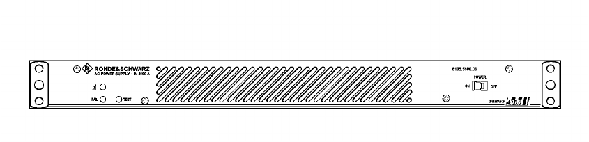
065 75$16&(,9(5 ; $ ; $
Operator’s Manual • User Information
6076.0822.12.01 – 1.3 –
5HTXLUHG3HUVRQQHO
Configuration of the M3SR Transceiver will have to be done by qualified personnel. Installation
and operation of the transceiver should be assigned to adequately skilled personnel.
The personnel must be familiar with this Operator’s Manual.
5HTXLUHG3RZHU6XSSO\
The M3SR Transceiver operates on a DC voltage of 28 VDC (19 to 31 VDC). This voltage is
provided by the external AC Power Supply IN 4000A (19" rackmount of 1 height unit) available
for the purpose. The connecting cable between transceiver and AC Power Supply IN 4000A is
available on demand.
The transceiver may also be powered by an external battery (22 to 31 VDC). An automatic
switchover facility integrated in the transceiver provides for automatic standby switchover in
case primary power fails.
)LJ 3RZHU6XSSO\,1 $
065 75$16&(,9(5 ; $ ; $
Operator’s Manual • User Information
– 1.4 – 6076.0822.12.01
'HVLJQHJ;7 $0RG
(See Fig. 1.3)
The M3SR Transceiver is accommodated in a sturdy 19" case of 3 height units, its top being
formed by a detachable screwed-down metal cover. After removing this cover, the modules of
XT 4410A become visible, which are:
qRadio Basis KR 4400, Mod. 04
It is formed by several items, namely the mechanical parts chassis and housing, which
accommodate the internal transceiver modules. Located in the left-hand part of the chas-
sis is the radio platform, containing a number of interface connectors for interfacing with
the internal subassemblies and also with the outside. For internal signal transfer a Radio
Module Bus, consisting of Radio Control Bus and Radio Data Bus, is available. Another
part of the radio basis is the Front Panel Unit, located directly at the front on the right. It
contains various control and display elements such as LEDs and buttons, external con-
nectors as well as a loudspeaker.
qVHF/UHF Receiver ET 4400 (main receiver)
The receiver is a plug-in module located in one of the slots in the centre left-hand part of
the chassis. It is of compact design, both sides being EMC-protected by appropriate
shielding covers. Once plugged into the radio platform in its assigned slot, the receiver is
held in place by quick-release fasteners.
qVHF/UHF Synthesizer GF 4400T
The synthesizer is a plug-in module located in one of the slots in the centre left-hand part
of the chassis. It is of compact design, both sides being EMC-protected by appropriate
shielding covers. Once plugged into the radio platform in its assigned slot, the synthesiz-
er is held in place by quick-release fasteners.
qInterface Module GH 4450
The interface module is a plug-in module in the left-hand rear part of the chassis. At its
top it carries several connectors for ribbon-cable connections towards the transmitter
unit. In addition, the plug-in module contains three interfaces for the rear modules.
qTransmitter Unit VT 4403, Mod. 02
The transmitter unit is a power module located in the right-hand part of the chassis and
extending over its full depth. It is made up of the actual transmitter board at the top and
the DC power supply located underneath. Both subassemblies are shielded by EMC cov-
ers. Also part of the transmitter unit is a heat sink with two fans, which are accommodated
directly at the rear, also on the right-hand side.
qControl Unit GB 4000C, Mod. 02
The control unit is located at the front on the left-hand side. It contains a display, control
and display elements such as LEDs, fixed-function keys and softkeys, a keypad and a
connector.
qUHF Filter FD 4430
The UHF filter is a plug-in module located in the centre left-hand part of the chassis, next
to the control unit. Once plugged into the radio platform in its assigned slot, the UHF filter
is held in place by quick-release fasteners.
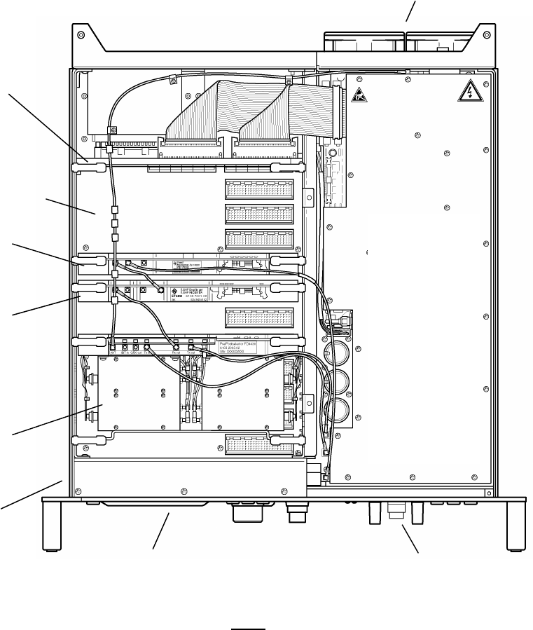
065 75$16&(,9(5 ; $ ; $
Operator’s Manual • User Information
6076.0822.12.01 – 1.5 –
)LJ 7RS9LHZRIHJ;7 $0RGZLWKRXW&RYHU
9+)8+)
7UDQVPLWWHU
%RDUG
with
'&3RZHU
6XSSO\
underneath
(both are part of
Transmitter Unit
VT 4403, Mod. 0
2)
+HDWVLQNZLWKWZRIDQV
(part of VT 4403, Mod. 02)
3RZHUPRGXOHV
)URQW3DQHO8QLW
(part of KR 4400)
,QWHUIDFH0RGXOH
*+
9+)8+)
6\QWKHVL]HU
*) 7
3OXJLQPRGXOHV
9+)8+)
5HFHLYHU
(7
)UDPH
(part of Ra-
dio Basis
KR 4400)
5DGLR3ODWIRUP
(
part of KR 4400)
&RQWURO8QLW*%&
0RG
1RWH
5DGLRSODWIRUPFRQQHFWRUVVKRZQZLWKRXW
SURWHFWLYHFDSV
8+))LOWHU
)'
065 75$16&(,9(5 ; $ ; $
Operator’s Manual • User Information
– 1.6 – 6076.0822.12.01
)XQFWLRQLQJHJ;7 $0RG
(See Fig. 1.4)
The Radio Platform contains the central processor (= server) of the M3SR Transceiver. Via
LAN/Ethernet, the server is connected to its clients. Clients may be an integrated Control Unit
GB 4000C (mod. 02) and/or further Control Units GB 4000C (mod. 03) connected via the LAN
connector X20 and a LAN hub, or customer-specific devices. The clients plus the software
package DS4400A form the MMI (= man-machine interface) of the M3SR Transceiver. Clients
are controlled by using the GB2PP protocol. The MMI guides the operator through menu-based
operating procedures and selectively visualizes all states on the display. Commands are en-
tered by making use of the control elements and the keypad. Operation and indication of the
transceiver’s operating status are both menu-oriented, operator interaction is performed via the
display and keyboard. The modules are controlled by the central processor via the Radio Mod-
ule Bus (RMB). The Radio Platform stores all parameters relating to the individual modules. A
system monitor monitors the temperatures and operating voltages. In a clock section all clock
signals needed by the radio platform are generated. The RMB connects the modules of
XT 4410A to one another and also to the central processor and the I/O interfaces. Serial inter-
faces are used for data transmission and remote control purposes. Parallel interfaces serve as
discrete inputs and outputs and control for instance an externally connected filter and / or am-
plifier. An Audio Frequency Interface (AFI) processes the analog signals in digital form so that
they can be transmitted digitally on the Radio Data Bus (RDB).
The Front Panel connected at the Radio Platform carries the control and display elements for
handling the basic transceiver functions. An Ethernet port is available for sending and receiving
data for service purposes (configuration and software download).
When the transceiver operates in receive mode, the RF signal is taken from antenna connector
X30 to the VHF/UHF Transmitter Board. From here it is routed via a Tx/Rx switch to the UHF
Filter FD 4430. The input stages of the filter are directly protected for electrostatic discharge.
The filter is working for the VHF/UHF Receiver ET 4400 (main receiver) as a preselector to re-
duce the interfering levels from other radios of the platform. In the main receiver, the RF signal
passes along a VHF path (100 to 224.975 MHz) or a UHF path (225 to 512 MHz) to the mixer
stages. The mixer stages get the LO signal (365 to 652 MHz) from VHF/UHF Synthesizer
GF 4400T. The AGC-controlled 2nd IF signal with a frequency of 455 kHz is demodulated in the
digital section of the receiver. The demodulated baseband signal is taken to the RDB for further
processing.
In transmit operation, VHF/UHF Synthesizer GF 4400T generates a carrier frequency in the
range from 100 MHz to 512 MHz. For amplitude modulation, this carrier frequency is modu-
lated by the VHF/UHF Transmitter Board. FM signals (both analog FM and digital FSK signals)
are generated by the synthesizer to be merely amplified by the VHF/UHF Transmitter Board
(signal RF_Drive). After amplification and filtering, the resulting signal is made available at an-
tenna connector X30. The UHF Filter FD 4430 is working as postselector. The filter chain is
located within the transmit path of the radio. The selectivity of the filter chain reduces the trans-
mitted noise energy of the radio which may degrade the sensitivity of other receiving radios on
the platform.
Interface Module GH 4450 connects the RMB and discrete signals between the Radio Plat-
form, the VHF/UHF Transmitter Board and up to three further rear modules. Switchover be-
tween transmission and reception is effected via the RMB.
The integrated DC Power Supply uses the +28-VDC input voltage to generate all voltages re-
quired in XT 4410A.

065 75$16&(,9(5 ; $ ; $
Operator’s Manual • User Information
6076.0822.12.01 – 1.7 –
)LJ %ORFN'LDJUDPRIHJ;7 $0RG
&RQWURO8QLW
9+)8+)
5HFHLYHU
(7
9+)8+)
6\QWKHVL]HU
*) 7
*%&0RG
5DGLR 3ODWIRUP
5()B,1 ;
5()B287 ;
$PS)LO;
$PS)LO ;
0LVF ;
0LVF;
56 ;
56 ;
$);
$);
'LVSOD\ .H\ERDUG
.'' ;
.'' ;(WKHUQHW ; +HDGVHW ;
5[
(WKHUQHW ;
)URQW 3DQHO
µ&
&ORFN
50%
$XGLR
,2,QWHUIDFHV
6HULDO3DUDOOHO
(WKHUQHW
)UHTXHQF\
,QWHUIDFH
6HFWLRQ
5DGLR %DVLV
.5
6HUYHU
&OLHQW
(WKHUQHW
(WKHUQHW
8+)
)LOWHU
)'
/2B5[
,QWHUIDFH
%RDUG
*+
%$77(5< ;
5)B'ULYH
9+)8+)
7UDQVPLWWHU
%RDUG
'&
3RZHU
6XSSO\
'&B,1 ;
&21752/;
$QWHQQD ;
7UDQVPLWWHU 8QLW
97
5[B,Q
7[B,Q
7[B2XW
5[B2XW
065 75$16&(,9(5 ; $ ; $
Operator’s Manual • User Information
– 1.8 – 6076.0822.12.01
*HQHUDO'DWD
See data sheet for Digital Programmable Software Radios of Series M3SR in Appendix A1.
065 75$16&(,9(5 ; $ ; $
Operator’s Manual • User Information
6076.0822.12.01 – 1.9 –
'HWDLOHG 6DIHW\ 5XOHV
Establish the cabling only if the transceiver is switched off.
When fitting operating rooms and installing and operating electrical equipment, the relevant na-
tional and international safety provisions and regulations have to be adhered to.
The following safety instructions apply in particular:
qIEC 364
qVDE 0100
qDIN 57100
These safety regulations deal with the following subjects:
ÇProtective measures:
Prevention of accidents
Overvoltage protection
Insulation of equipment
Grounding
ÇType and laying of lines and cables
ÇProvisions for operational facilities, rooms and equipment requiring special handling

065 75$16&(,9(5 ; $ ; $
Operator’s Manual • User Information
– 1.10 – 6076.0822.12.01
$FFHVVRULHV
3RZHU6XSSO\
IN 4000A
$QWHQQDV
HK 014
not shown:
HK 012
HK 001
&RQWURO8QLWV
GB 4000C, mod. 03
(remote version)
not shown:
GB 406.. on request
)LOWHUDQG$PSOLILHUV
FD 430
not shown:
VU 210L
VU 220L
VD 480L
+DQGVHWVDQG+HDGVHWV
GA 015
not shown:
GA 012
GA 013
GA 016H1
0DWLQJ&RQQHFWRU
not shown:
ZF 4410
065 75$16&(,9(5 ; $ ; $
Operator’s Manual • Use under Normal Conditions
6076.0822.12.01 – 2.1 –
8VH XQGHU 1RUPDO &RQGLWLRQV
,QWURGXFWLRQ
This chapter provides information concerning
qUnpacking and checking
qInstallation into a 19" rack
qBasic cabling
qOperation
- Introduction to Displays and Controls
- Switching the Transceiver On and Off
- Menu RADIO CONNECTION
- Menu COMLINE SESSION
- Menu MAIN
- Menu MANUAL FIX. FRQ
- Menu USER PRESET FIX.FRQ
- Menu EMERGENCY MODE
8QSDFNLQJDQG&KHFNLQJ
After delivery carry out the following steps:
1. Unpack the transceiver.
2. Check if delivery (transceiver and accessories) is complete by referring to the delivery
note.
3. Check the transceiver and accessories for signs of damage which may have occurred
during transit.
4. Contact the shipping agent immediately, if damage is found.
5. Keep the packaging (box etc.) for later use, e.g. if the transceiver is to be sent to the near-
est R&S representative for repair (see address list following the title page of this manual).
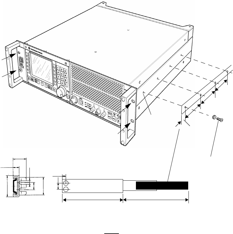
065 75$16&(,9(5 ; $ ; $
Operator’s Manual • Use under Normal Conditions
– 2.2 – 6076.0822.12.01
,QVWDOODWLRQLQWRD5DFN
(See drawing 6102.4002.01DF at the end of this chapter)
1RWH
7KHWHOHVFRSLFVOLGHVDUHDYDLODEOHRQGHPDQGLGHQWQRRQO\IRUUDFNVSURYLG
LQJIRUDVHDWHGGHSWKRIPPDQGDFFHVVLEOHIURPWKHUHDURUIRUWUDLOLQJFD
EOHLQVWDOODWLRQ
)L[LQJ DWUDFN
IURQW
HJ; $
([WHQVLRQ
6LGHOHQJWK
[3KLOOLSVVFUHZV
0[
,GHQWQR
[:DVKHU
,GHQWQR
0D[VFUHZLQ
GHSWKPP
/RDGUDWLQJIRUHDFKVOLGHSDLU
1
,GHQWQR
065 75$16&(,9(5 ; $ ; $
Operator’s Manual • Use under Normal Conditions
6076.0822.12.01 – 2.3 –
For installation into a 19" rack with telescopic slides proceed as follows:
1. Take the right-hand telescopic slide and extend it as far as it goes.
2. Press the automatic unlocking device and pull the innermost slide completely out.
3. Attach the innermost slide to the right-hand side panel of the transceiver by means of four
Phillips screws and the associated washers (see figure above).
4. Take the left-hand telescopic slide and extend it as far as it goes.
5. Press the automatic unlocking device and pull the innermost slide completely out.
6. Attach the innermost slide to the left-hand side panel of the transceiver by means of four
Phillips screws and the associated washers (see figure above).
7. Take the outer telescopic slides and mount them to the rack.
8. Insert the transceiver, with its slides fitted, into the extended slides of the rack and slide
it in until the stop is reached.
9. Fasten the transceiver to the rack using four screws.
10. Cable the transceiver at its rear acc. to chapter 2.4.

065 75$16&(,9(5 ; $ ; $
Operator’s Manual • Use under Normal Conditions
– 2.4 – 6076.0822.12.01
%DVLF&DEOLQJ
&$87,21
&RQQHFWWKHPDLQVFDEOHRQO\DIWHUDOORWKHUFDEOLQJKDVEHHQPDGH
065 7UDQVFHLYHUHJ;7 $
5HDU&DEOLQJ
Cabling to be made at the rear:
X31: DC IN is protected against reverse polarity (no function in this case).
1RWH
7KHFRQQHFWLQJFDEOHEHWZHHQFRQQHFWRU;'& ,1RI;7 $DQGFRQQHFWRU;RI$&
3RZHU6XSSO\,1 $LVDYDLODEOHRQGHPDQGRUGHUQXPEHUOHQJWK P
X32: Optional battery connection (+19 to +31 VDC, ≤25 A) for automatic switchover in the
case of power failure.
GND
GND
HJ;7 $
,1$
X1 AC Mains
(85 to 265 VAC)
X32 Battery
24 VDC (19to31VDC)
X31 DC IN
X30 to Antenna
X2
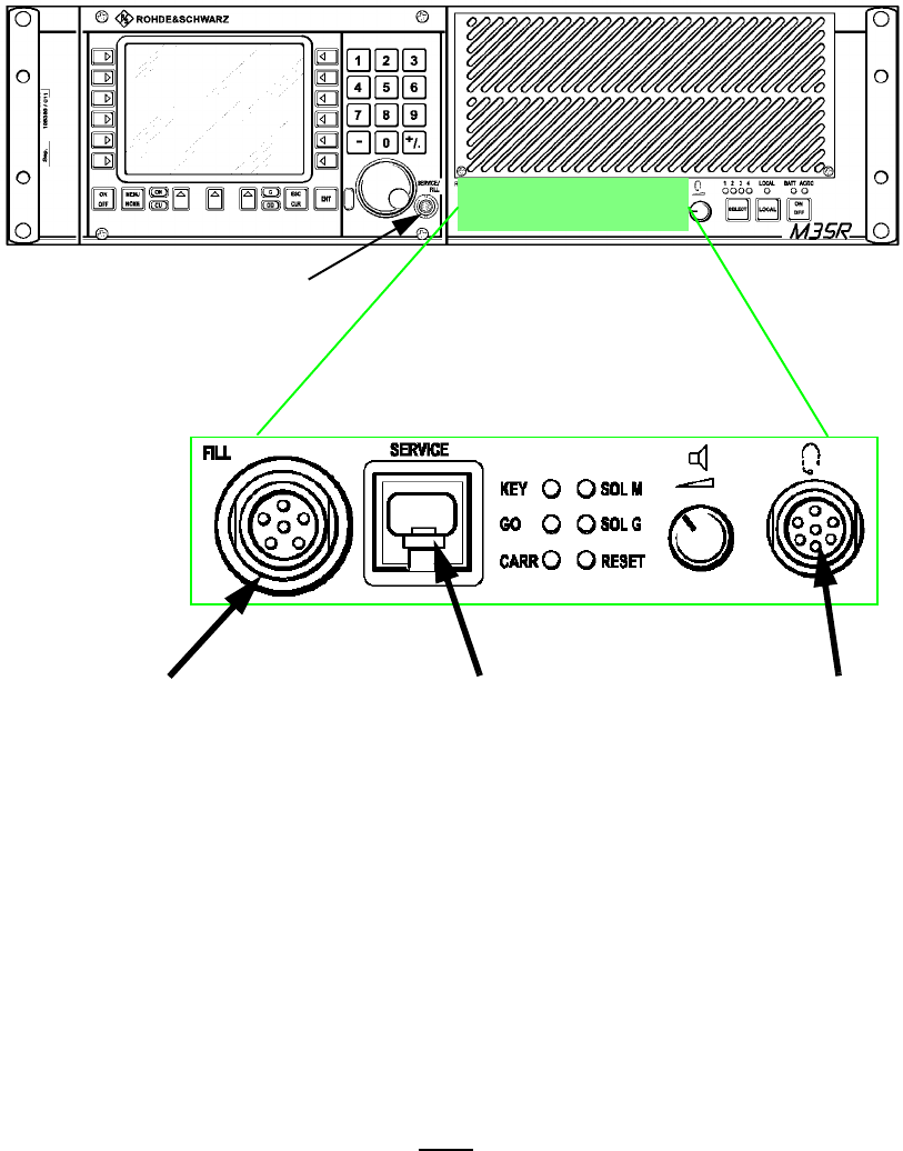
065 75$16&(,9(5 ; $ ; $
Operator’s Manual • Use under Normal Conditions
6076.0822.12.01 – 2.5 –
)URQW&DEOLQJ
Cabling to be made at the front:
1RWH
)RUGHWDLOHGLQIRUPDWLRQRQFRQQHFWRUVDQGFRQWDFWDVVLJQPHQW
VHHLQWHUIDFHGHVFULSWLRQLQ$SSHQGL[$7HFKQLFDO,QIRUPDWLRQ
&RQQHFWRU
IRUIXWXUHXVH
)LOO*XQ&RQQHFWRU
not used
6HUYLFH&RQQHFWRU
used for connecting a PC
for
•remote control
•software download
•monitoring
•analysis
&RQQHFWRU IRU
+HDGVHW*$
used for LOCAL
mode operation
(voice)

065 75$16&(,9(5 ; $ ; $
Operator’s Manual • Use under Normal Conditions
– 2.6 – 6076.0822.12.01
065 7UDQVFHLYHUHJ;7 $
5HDU&DEOLQJ
Cabling to be made at the rear:
X31: DC IN is protected against reverse polarity (no function in this case).
1RWH
7KHFRQQHFWLQJFDEOHEHWZHHQFRQQHFWRU;'& ,1RI;7 $DQGFRQQHFWRU;RI$&
3RZHU6XSSO\,1 $LVDYDLODEOHRQGHPDQGRUGHUQXPEHUOHQJWK P
X32: Optional battery connection (+19 to +31 VDC, ≤25 A) for automatic switchover in the
case of power failure.
GND ,1$
X1 AC Mains
(85 to 265 VAC)
X32 Battery
24 VDC (19to31VDC)
X31 DC IN
X30 to Antenna
X2
X20 LAN
X44 LAN
X33 Control
24 V (external,
switched)
GND GND
*%&0RG
HJ;7 $
X42 Battery
24 VDC (19 to 31 VDC)

065 75$16&(,9(5 ; $ ; $
Operator’s Manual • Use under Normal Conditions
6076.0822.12.01 – 2.7 –
)URQW&DEOLQJ
Cabling to be made at the front:
1RWH
)RUGHWDLOHGLQIRUPDWLRQRQFRQQHFWRUVDQGFRQWDFWDVVLJQPHQW
VHHLQWHUIDFHGHVFULSWLRQLQ$SSHQGL[$7HFKQLFDO,QIRUPDWLRQ
6HUYLFH&RQQHFWRU
used for connecting a PC
for
•remote control
•software download
•monitoring
•analysis
&RQQHFWRUIRU
+HDGVHW*$
not used
)LOO*XQ&RQQHFWRU
not used
065 75$16&(,9(5 ; $ ; $
Operator’s Manual • Use under Normal Conditions
– 2.8 – 6076.0822.12.02
2SHUDWLRQ
,QWURGXFWLRQWR'LVSOD\VDQG&RQWUROV
For transceiver control, a multi-function man-machine interface is provided, featuring
qDisplay
qSoftkeys (menu-dependent multi-functional keys)
qKeys with a fixed function (such as ON / OFF switch, ENTER key, numerical keypad, cur-
sor control keys)
qKey combinations
qControls (such as volume control and rotary knob)
qIndicators (LEDs signalling the operating status)

065 75$16&(,9(5 ; $ ; $
Operator’s Manual • Use under Normal Conditions
6076.0822.12.02 – 2.9 –
'LVSOD\RQO\; $
Reflecting its design as a software radio, the M3SR Transceiver controlled via GB 4000C relies
on a menu-based control concept, the operator being guided through the individual menus and
submenus and having a variety of selection options.
This chapter assumes that the individual functions or submenus are called up starting on the
main menu level. If necessary, press key MENU HOME (see chapter 2.5.1.4) to go to the main
menu straight from any other level.
)LJ 'HVLJQRI'LVSOD\3ULQFLSOH
Calls the
previous
menu
,QIRUPDWLRQ(GLW %R[
Overview of operating states
and fields for manual inputs
depending on the selected
operating mode
0HQX1R5DGLR$GGU&RQWURO 8QLW $GGU
0HQX7LWOH
7LWOH $UHD RI 0HQX
'LVSOD\)LHOGVZLWK6RIWNH\1DPHV
By using the associated softkeys various
functions and parameter settings can be
selected depending on the active menu
Calls the next page
of the same menu
/
L is only displayed if key
LOCAL is pressed (LOCAL
mode).

065 75$16&(,9(5 ; $ ; $
Operator’s Manual • Use under Normal Conditions
– 2.10 – 6076.0822.12.02
6RIWNH\VRQO\; $
2.5.1.2.1 Softkey Numbers
The softkey numbering as shown by the example above is maintained throughout this chapter.
2.5.1.2.2 Explanation of Softkey Symbols
The use of symbols in the menu-dependent softkey designations follows some simple rules:
This menu contains two pages. The page currently shown is page one.
One menu is following, which is opened by pressing the softkey. The cur-
rent setting is shown in the direction pointed out by the black arrowhead.
Example:
This menu is disabled right now (letters light-faced, i.e. not bold) or it is not
present.
Softkey
No.
Softkey
No.

065 75$16&(,9(5 ; $ ; $
Operator’s Manual • Use under Normal Conditions
6076.0822.12.02 – 2.11 –
Some basic concepts need to be explained in order to fully understand the following chapters.
One menu is following. The current setting is shown in the second line (ex-
ample: HIGH).
Example:
Toggle switch with two functions, the currently active function is high-
lighted.
Fixed function: The tone is produced as long as you keep pressing the
key.
(Three dots): Further menus are following.
After pressing the associated softkey a parameter can be entered/edited
manually. In the direction pointed out by the arrowhead, the value (e.g. fre-
quency) is displayed.
Example:
Press to return to previous menu.
The asterisk (*) indicates that the new settings have not yet been stored.
When the menu is left without storing the new settings, a warning comes
up.
+Press softkey SAVE * to save the current data or
+Press key ENT to discard the
changes and leave.

065 75$16&(,9(5 ; $ ; $
Operator’s Manual • Use under Normal Conditions
– 2.12 – 6076.0822.12.02
2.5.1.2.3 Value Selection
qSelection within a set of values (example: power) can be made in different ways:
1. Press the appropriate softkey associated to the relevant display field as many times as
required, selection being made in forward direction. Confirm by pressing the ENTER key.
The previously set value remains highlighted until a new setting is selected and con-
firmed with ENTER.
Example:
2. Select by turning the tuning knob (in either direction). Confirm by pressing the ENTER
key.
Example:
qNumerical values (example: frequency) can be set by using either the numerical keypad
or the tuning knob and the ENTER key.
Example:
and
Softkey
and
Tuning Knob
or
and
and
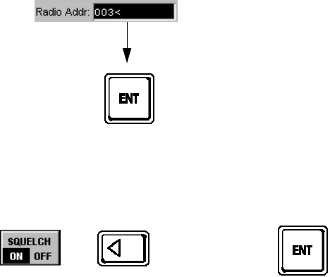
065 75$16&(,9(5 ; $ ; $
Operator’s Manual • Use under Normal Conditions
6076.0822.12.02 – 2.13 –
qAn arrow after a figure means that if this numerical value has been changed it must be
confirmed with ENTER.
Example:
qToggle switches are actuated by just pressing the appropriate softkey, i.e. without
ENTER.
Example:
without
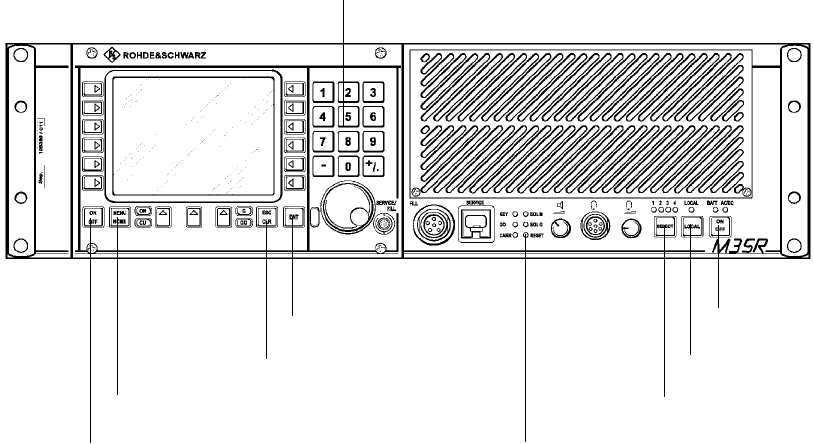
065 75$16&(,9(5 ; $ ; $
Operator’s Manual • Use under Normal Conditions
– 2.14 – 6076.0822.12.02
.H\VZLWK)L[HG)XQFWLRQ
q212)) Key (Control Unit GB 4000)
Switching the transceiver on (but not off), or during operation switching the display off and
on again.
q0(18+20( Key (Control Unit GB 4000)
Switching the transceiver to the Menu 040 (MAIN) straight from any other level.
q(6&&/5 Key (Control Unit GB 4000)
Deleting entries or aborting processes.
q(17 Key (Control Unit GB 4000)
Confirming entries or initiating processes.
qNumerical keypad (Control Unit GB 4000)
Input of numerical values and decimal point and in- or decrementing selection.
q5(6(7 Button (Front Panel)
When pressing this button all software in the transceiver will be reset and after a short
time the software will be restarted. The last activated menu will be displayed.
Key ON / OFF *)
Key MENU HOME *)
Button RESET
Key ESC / CLR *)
Key ON / OF
F
Key ENT *)
Key LOCAL
Key SELECT
Numerical keypad *)
*) only X. 4410A
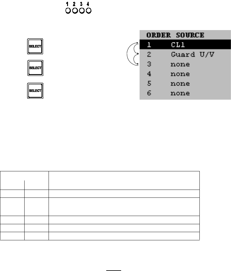
065 75$16&(,9(5 ; $ ; $
Operator’s Manual • Use under Normal Conditions
6076.0822.12.02 – 2.15 –
q6(/(&7 Key (Front Panel)
By using the SELECT key one of the AF sources for the loudspeaker can be selected that
have been configured in Menu 575 (FRONTPANEL AUDIO SOURCE), e.g. CL1 (Com-
line) or Guard U/V. A Comline is a functional unit of radio modules.
When CL1 is selected as AF source and communication mode V/D UNCP is active, the
guard receiver AF signal can be output at the loudspeaker in addition to the main receiver
AF signal, depending on the GUARD configuration (see Menu 110, page 1 (MANUAL
FIX.FRQ) and Menu 210, page 1(MANUAL PRESET FIX.FRQ)).
After power-on, Comline 1 is selected by default. This is indicated by illumination of
LED 1.
The following table shows how LEDs 1 and 2 are related and which AF signal is output
by the loudspeaker:
q/2&$/ Key (Front Panel)
1RWH
8VLQJWKLVNH\RQO\PDNHVVHQVHZLWK065 7UDQVFHLYHU; $
Activate local mode.
LED LOCAL lights up.
In the menu title area an ’L’ comes up.
The transceiver is controlled exclusively via Control Unit GB 4000C, mod. 02. In local
mode the same functions are available as in remote mode, although here only commu-
nication mode V/D UNCP makes sense.
LED AF signal
12
no AF signal
OLJKWHG AF signal of main receiver and in addition of guard receiver, if
switched on via softkey GUARD in Menu 110 (MANUAL
FIX.FRQ) or 210 (USER PRESET FIX.FRQ).
IODVKLQJ AF signal of guard receiver (VHF band)
IODVKLQJ AF signal of guard receiver (UHF band)
IODVKLQJ IODVKLQJ AF signal of guard receiver (VHF and UHF bands)
LED 1 lighted
1. Press key LED 1 and 2 flashing
2. Press key none of the LEDs lighted
3. Press key LED 1 lighted

065 75$16&(,9(5 ; $ ; $
Operator’s Manual • Use under Normal Conditions
– 2.16 – 6076.0822.12.02
Running remote control sessions (fixed, advanced) are terminated.
Control units, which may be connected, are able to operate in remote control sessions
(monitoring) only.
In local mode the four audio lines (NB1, WB1, NB2, WB2) have no function. In voice
mode (V/D UNCP) the signal from the headset interface is used for carrier modulation.
The demodulated AF signal will be made available also at the headset interface.
ALC (automatic level control) is performed in the front panel unit, compensating volume
variations of voice signals. The Tx ALC cannot be disconnected.
Carrier activation is performed in voice mode (V/D UNCP) via the headset interface.
In Menu 550 (PTT COMLINE MAPPING) the four PTT lines (PTT_1, PTT_1L, PTT_2,
PTT_2L) can be configured also for local mode. For more details on PTT mapping refer
to chapter 3.
1RWH
:HUHFRPPHQGQRWWRFRQILJXUHWKH377OLQHVIRUORFDOPRGH
DVWKLVPD\UHVXOWLQXQZDQWHGFDUULHUDFWLYDWLRQE\RQHRIWKHFRQQHFWHGGHYLFHV
When local mode is left by pressing the LOCAL key, all settings which were active when
remote mode was last left will be reactivated. However, changes made in Menus 400
(RADIO MAINTENANCE) and 600 (RADIO SETUP) will be preserved!
For more details on communication modes, sessions, line mapping etc. see chapter 3.
q212)) Key (Front Panel)
Switching the transceiver on or off.

065 75$16&(,9(5 ; $ ; $
Operator’s Manual • Use under Normal Conditions
6076.0822.12.02 – 2.17 –
.H\&RPELQDWLRQV
By hitting the following key combinations on Control Unit GB 4000C and the Front Panel, re-
spectively, special commands can be given to the M3SR Transceiver.
.H\FRPELQDWLRQRQ&RQWURO8QLW
RQO\; $'HVFULSWLRQ HIIHFWRQ065 7UDQVFHLYHU
(6&&/5 and 212))
or
(6&&/5 and .H\
The radio initiates an Emergency Clear.
This works always, i.e. also in a Monitoring Ses-
sion. No Advanced or Fixed Session is re-
quired.
Zeroize is available as output signal at connec-
tor contact X26.24 (AF1) (refer to interface de-
scription in Appendix A1).
In the case that a Cipher Unit KY58 is con-
nected, emergency clear will erase the KY58
data.
0(18+20( and (17 at the same timeInitiates the procedure for system PIN number
input (see chapter 3).
System PIN numbers cannot be changed since
they are firmly tied to the hardware.
The following 4 keys at the same time:
8SSHU OHIW VRIWNH\ and 212)) and
XSSHU ULJKWVRIWNH\ and (17
Initiates a control unit RESET.
The control unit then re-establishes the remote
control connection to the radio and displays the
last menu active before the RESET.
.H\FRPELQDWLRQRQ)URQW3DQHO 'HVFULSWLRQ HIIHFWRQ065 7UDQVFHLYHU
6(/(&7 and 10 x /2&$/ within 10 sec Sets the default IP (Internet Protocol) address:
Platform CPLAT set to 192.168.52.46
This is necessary when incorrect IP addresses
were entered and the default IP address is to be
used again for establishing a remote control
connection to a radio.
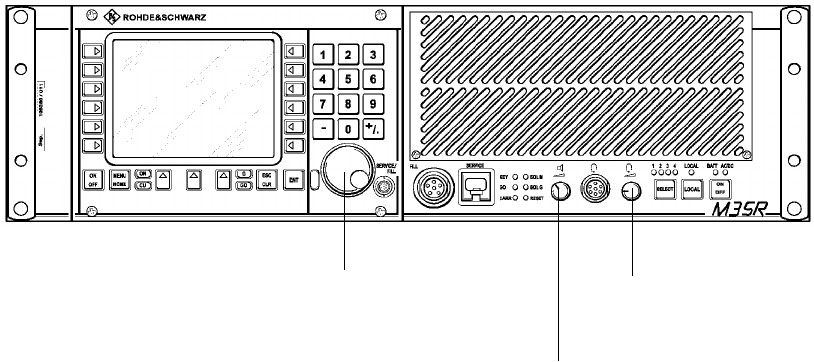
065 75$16&(,9(5 ; $ ; $
Operator’s Manual • Use under Normal Conditions
– 2.18 – 6076.0822.12.02
&RQWUROV
qTuning Knob (Control Unit GB 4000)
Selecting values.
qLoudspeaker Volume Control (Front Panel)
Adjusting volume:
Low: control turned fully counter-clockwise
Full: control turned fully clockwise
qHeadphone Volume Control (Front Panel)
Adjusting volume:
Low: control turned fully counter-clockwise
Full: control turned fully clockwise
Volume Control
Loudspeaker
Tuning Knob
(only X. 4410A) Volume Control
Headphone
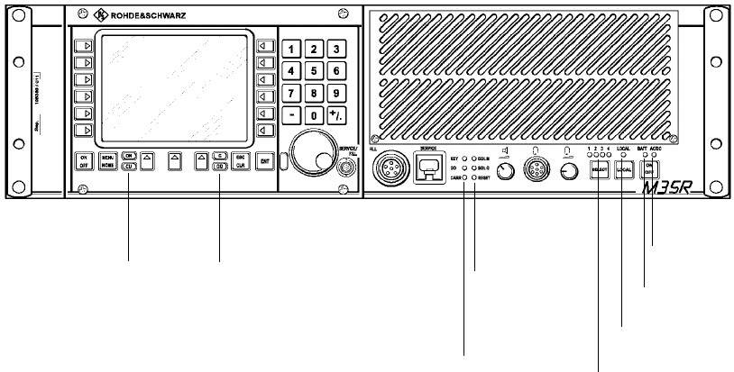
065 75$16&(,9(5 ; $ ; $
Operator’s Manual • Use under Normal Conditions
6076.0822.12.02 – 2.19 –
,QGLFDWRUV
qLED 21 (Control Unit GB 4000)
is illuminated when the control unit is on.
qLED &8 (Control Unit GB 4000)
is illuminated when the control unit is fully operative.
qLED * (Control Unit GB 4000)
lights up when the guard receiver squelch opens.
qLED *2 (Control Unit GB 4000)
is illuminated when the transceiver is fully operative.
qLED .(< (Front Panel)
signals that a device connected at the Fill Gun connector has been detected and that the
transceiver is ready to load data.
qLED *2 (Front Panel)
signals that the M3SR Transceiver is fully operative.
qLED &$55 (Front Panel)
signals availability of a carrier signal at the antenna connector in transmit operation.
qLED 64/ 0 (Front Panel)
indicates reception of a signal by (main) Receiver ET 4400 (squelch).
LED ON *)
LED CU *) LED G *)
LED GO *)
LED KEY
LED GO
LED CARR
LED SQL M
LED SQL G
LED LOCAL
LEDs 1 to 4
LED BATT
LED AC/DC
*) only X. 4410A

065 75$16&(,9(5 ; $ ; $
Operator’s Manual • Use under Normal Conditions
– 2.20 – 6076.0822.12.02
qLED 64/ * (Front Panel)
indicates reception of a signal by Guard Receiver ET 4400G.
qLEDs to (Front Panel)
indicate which signal is being output via the loudspeaker (3 + 4 presently not used):
qLED /2&$/ (Front Panel)
is illuminated when the LOCAL key has been pressed, indicating that the transceiver can
be controlled only locally via the integrated control unit. In addition, a headset (PTT key,
microphone), which may be connected, will be enabled as well.
qLED %$77 (Front Panel)
signals availability of battery power.
qLED $&'& (Front Panel)
signals availability of AC/DC power.
LED AF signal
1234
no AF signal
OLJKWHG AF signal of main receiver and in addition of guard
receiver, if switched on via softkey GUARD in Menu
110 (MANUAL FIX.FRQ) or 210 (USER PRESET
FIX.FRQ).
IODVKLQJ AF signal of guard receiver (VHF band)
IODVKLQJ AF Signal of guard receiver (UHF band)
IODVKLQJ IODVKLQJ AF signals of guard receiver (VHF and UHF bands)

065 75$16&(,9(5 ; $ ; $
Operator’s Manual • Use under Normal Conditions
6076.0822.12.02 – 2.21 –
6ZLWFKLQJWKH7UDQVFHLYHU2QDQG2II
0657UDQVFHLYHU; $
2.5.2.1.1 Minimum Requirements
Before putting the M3SR Transceiver X. 4410A into operation make sure that the following min-
imum requirements are met:
•AC Power Supply IN 4000A (or a battery complying with the technical specifications) is
available.
•Antenna is connected.
•Handset or headset is connected.
•See also chapter 2.4 "Basic Cabling".
2.5.2.1.2 Switching On
1RWH
:KHQVWDUWLQJXSWKHWUDQVFHLYHUWKHODVWPHQXZKLFKZDVDFWLYHEHIRUHVZLWFKLQJRII
LVFDOOHGXSDJDLQRUWKHSURPSWIRU3,1HQWU\FRPHVXSLIWKHODVWPHQXZDV3,1SURWHFWHG
+Press key ON / OFF on the Front Panel or Control Unit GB 4000C (see figure).
.H\212)) .H\212))
switches the transceiver on
(but not off), or during opera-
tion switches the display off
and on again
switches the transceiver
on / off
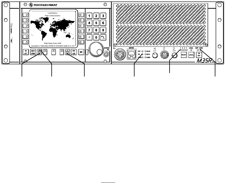
065 75$16&(,9(5 ; $ ; $
Operator’s Manual • Use under Normal Conditions
– 2.22 – 6076.0822.12.02
qAll LEDs pointed out above are illuminated to indicate readiness for operation, their indi-
vidual messages are:
LED ON: control unit ready for operation
LED CU: control unit ok
LEDs GO: radio ok
LED AC/DC: power available
LED 1: indicates which signal is being output via the loudspeaker
1RWH
,I/('UHPDLQVGDUNSUHVVWKH6(/(&7NH\
qThe last activated menu is called up again, or the prompt for PIN entry comes up if the
last menu was PIN-protected.
/('&8 /('21/('*2 /('*2 /('$&'&
/('

065 75$16&(,9(5 ; $ ; $
Operator’s Manual • Use under Normal Conditions
6076.0822.12.02 – 2.23 –
2.5.2.1.3 Switching Off
+Press key ON / OFF on the Front Panel.
qControl Unit GB 4000C, mod. 02 (left-hand part of the control panel) may be switched off
separately by using the ON/OFF key on its front panel. In this case the display will go dark
although the radio is still operative.
1RWH
7KHFRQWUROXQLWGLVSOD\ZLOODOVREHGDUNZKLOHWKHVFUHHQVDYHULVDFWLYH
+Press key ON/OFF.
qDisplay goes dark and LED ON is
extinguished.
.H\212))
switches the transceiver
on / off
/('21
.H\212))
switches the control unit
display off and on

065 75$16&(,9(5 ; $ ; $
Operator’s Manual • Use under Normal Conditions
– 2.24 – 6076.0822.12.02
065 7UDQVFHLYHU; $
2.5.2.2.1 Minimum Requirements
Before putting the M3SR Transceiver X. 4460A into operation make sure that the following
minimum requirements are met:
•Control Unit GB 4000C, mod. 03 (remote version) is connected with the transceiver via
LAN.
•Control Unit GB 4000C, mod. 03 is connected with the power distribution system.
•AC Power Supply IN 4000A (or a battery complying with the technical specifications) is
available.
•Antenna is connected.
•See also chapter 2.4 "Basic Cabling".
2.5.2.2.2 Switching On
+Press key ON / OFF on the Front Panel (see figure).
+Press key ON / OFF on Control Unit GB 4000C, mod. 03.
.H\212))
switches the transceiver on / off
.H\212)) switches the control unit on / off

065 75$16&(,9(5 ; $ ; $
Operator’s Manual • Use under Normal Conditions
6076.0822.12.02 – 2.25 –
qAll LEDs pointed out above are illuminated to indicate readiness for operation, their indi-
vidual messages are:
LED ON: control unit ready for operation
LED CU: control unit ok
LEDs GO: radio ok
LED AC/DC: power available
LED 1: indicates which signal is being output via the loudspeaker
1RWH
,I/('UHPDLQVGDUNSUHVVWKH6(/(&7NH\
qThe last activated menu is called up again, or the prompt for PIN entry comes up if the
last menu was PIN-protected.
/('*2 /('$&'&
/('&8 /('21/('*2
Control Unit GB 4000C, Mod. 03 /('

065 75$16&(,9(5 ; $ ; $
Operator’s Manual • Use under Normal Conditions
– 2.26 – 6076.0822.12.02
2.5.2.2.3 Switching Off
+Press key ON / OFF on Control Unit GB 4000C, mod. 03.
qLED ON is extinguished.
+Press key ON / OFF on the Front Panel.
/('21
.H\212)) switches the control unit display off and on
.H\212))
switches the transceiver
on / off
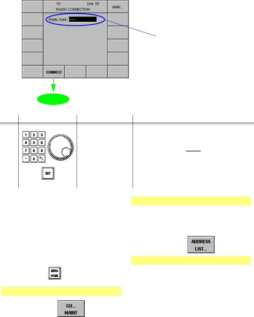
065 75$16&(,9(5 ; $ ; $
Operator’s Manual • Use under Normal Conditions
6076.0822.12.02 – 2.27 –
0HQX5$',2&211(&7,21
Via Menu 010 the link setup between Control Unit GB 4000C and the radio is done.
Starting point: Switching On
qThe following display appears:
No. Control Action Notes
Set address.
Confirm with
ENTER.
Setting logical radio address in the range
from 001 to 999.
1RWH
:KHQWKH065 7UDQVFHLYHULVRSHUDWHGLQ
DQHWZRUNWKHDGGUHVVHVQHHGWREHFRQILJ
XUHGYLD0HQXV5$',2$''5(66
5287($''5(66/,67DQG
&8$''5(665287(
Address edit field
0HQX
:KHQSXWWLQJWKHUDGLRLQWRRSHUDWLRQWKH
ILUVWWLPH
+Enter default address 46.
:KHQWKHHQWHUHGDGGUHVVGRHVQRWSHUPLW
WRFRQQHFWWRWKHWUDQVFHLYHU
C
heck if the address is in the control unit’s ad-
d
ress list.
1. Press key
Menu 040 (MAIN)
2. Press softkey
Menu 800 (CU MAINTENANCE)
3. Enter control unit maintenance PIN
number by using the numerical key-
pad, then press enter.
4. Press softkey
Menu 835 (CU ADDRESS LIST)
ÇThis menu displays all addresses of
devices the control unit can connect
to.
ÇIf necessary, enter the required ad-
dress in the address list.
065 75$16&(,9(5 ; $ ; $
Operator’s Manual • Use under Normal Conditions
– 2.28 – 6076.0822.12.02
0HQX&20/,1(6(66,21
In Menu 020 the operator can define the level of access, switch from COMLINE Session to
RADIO Session (Menu 030) or cut the connection between control unit and radio, if necessary.
The COMLINE session is the normal operating mode of the radio where all the COMLINE radio
operation parameters are set via Menus
•110 (MANUAL FIX.FRQ),
•210 (USER PRESET FIX.FRQ) and
•300 (EMERGENCY).
Menus 400 (RADIO MAINTENANCE), 600 (SETUP) and 800 (CU MAINTENANCE) are acces-
sible only by entering the respective PINs. The assignment of modules to particular Comlines
cannot be changed in a COMLINE session. For this a RADIO session is required, which is ac-
tivated by entry of the respective PIN.
In the COMLINE session the following three levels of access are available:
qFIXED
qADVANCED
qMONITOR

065 75$16&(,9(5 ; $ ; $
Operator’s Manual • Use under Normal Conditions
6076.0822.12.02 – 2.29 –
•FIXED
- In a FIXED COMLINE session, a fixed remote control connection is established be-
tween the own control unit and the radio which cannot be broken by third parties.
- Therefore FIXED COMLINE session is used whenever continuous remote control is
required.
•ADVANCED
- In an ADVANCED COMLINE session, the remote control connection between a con-
trol unit and the radio can be broken by a third party. When another control unit has
taken remote control of the radio, the display of the local control unit visualizes a mes-
sage to this effect.
- ADVANCED COMLINE session is used in normal radio control operation.
•MONITOR
- In a MONITOR COMLINE session, the operator is able to passively monitor on the dis-
play of the control unit how control of the radio by another control unit is proceeding.
Active radio control via the own control unit is disabled.
- MONITOR COMLINE session is used for monitoring radio control.
- MONITOR COMLINE session suffices for maintenance actions accessible via PIN.
&$87,21
,QD),;('&20/,1(VHVVLRQLWLVLPSRVVLEOHIRUIXUWKHUFRQWUROXQLWVZKLFKPD
\
EHFRQQHFWHGWRWDNHUHPRWHFRQWURORIWKHUDGLR$QH[FHSWLRQWRWKLVLV/2&$/
PRGHZKLFKKDVWRSSULRULW\6RZKHQSUHVVLQJWKH/2&$/NH\D),;('&20/,1
(
VHVVLRQZLOOEHLQWHUUXSWHG
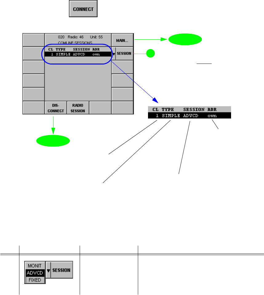
065 75$16&(,9(5 ; $ ; $
Operator’s Manual • Use under Normal Conditions
– 2.30 – 6076.0822.12.02
Starting point: Menu 010 (RADIO CONNECTION)
+Press softkey (9) and the following display appears:
No. Control Action Notes
2 Press softkey
SESSION.
Select setting.
Selection of access level
021,7Only monitoring operation.
$'9&'Command authority can be withdrawn.
),;(' Command authority cannot be withdrawn.
softkey CONNECT
softkey DISCONNECT
Selected Comline
(only 1 is possible)
Type of radio connection
•SIMPLE
•S400U
•MASTER
•SLAVE
Access level
•blank = monitoring
•ADVCD
•FIXED
}
Remote control unit logica
l
address
•own
•001 to 999
•400U (protocol)
only split-site mode
0HQX
0HQX
1RWH
6RIWNH\5$',26(66,21
LVGHVFULEHGLQFKDSWHU
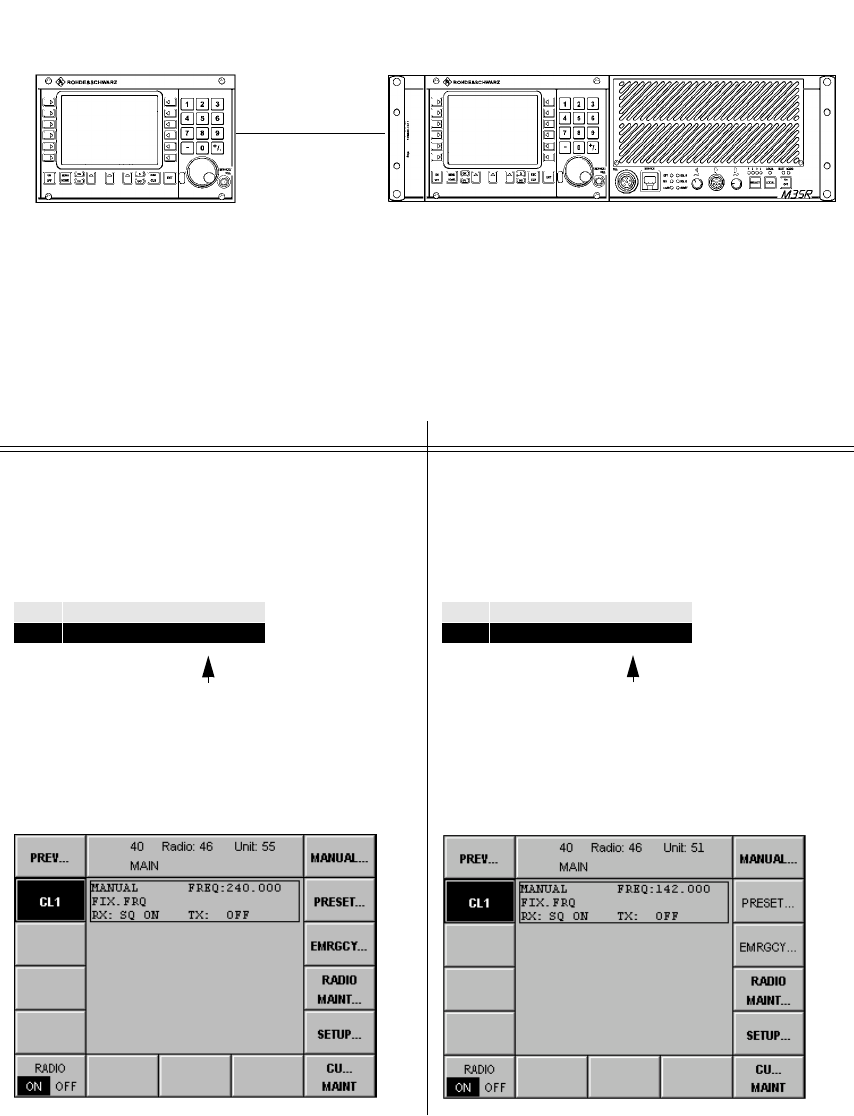
065 75$16&(,9(5 ; $ ; $
Operator’s Manual • Use under Normal Conditions
6076.0822.12.02 – 2.31 –
([DPSOH
The example below illustrates a control scenario of one transceiver and two control units, the
command authority changing between the two control units.
The M3SR Transceiver X. 4410A with local control unit (GB 4000C, mod. 02) may also be re-
mote-controlled by a Control Unit GB 4000C, mod. 03.
+Change access level to fixed
GB 4000C, mod. 03 - Unit 55 GB 4000C, mod. 02 - Unit 51
Access level: advanced
Control unit (55) controls transceiver with log-
ical address 46 (ADR = own).
Detail of Menu 030:
The operator sees that his control unit (55)
has advanced access level to the radio.
Menu 040:
Access level: monitoring
Control unit 51 can take control any time.
Detail of Menu 030:
The operator sees that it is not his control unit
(51) that has advanced access level to the ra-
dio, but control unit (55).
Menu 040:
GB 4000C, mod. 02
Unit: 51 X. 4410A
Radio: 46
GB 4000C, mod. 03
Unit: 55
CL TYPE SESSION ADR
1SIMPLE ADVCD own
CL TYPE SESSION ADR
1SIMPLE ADVCD 55
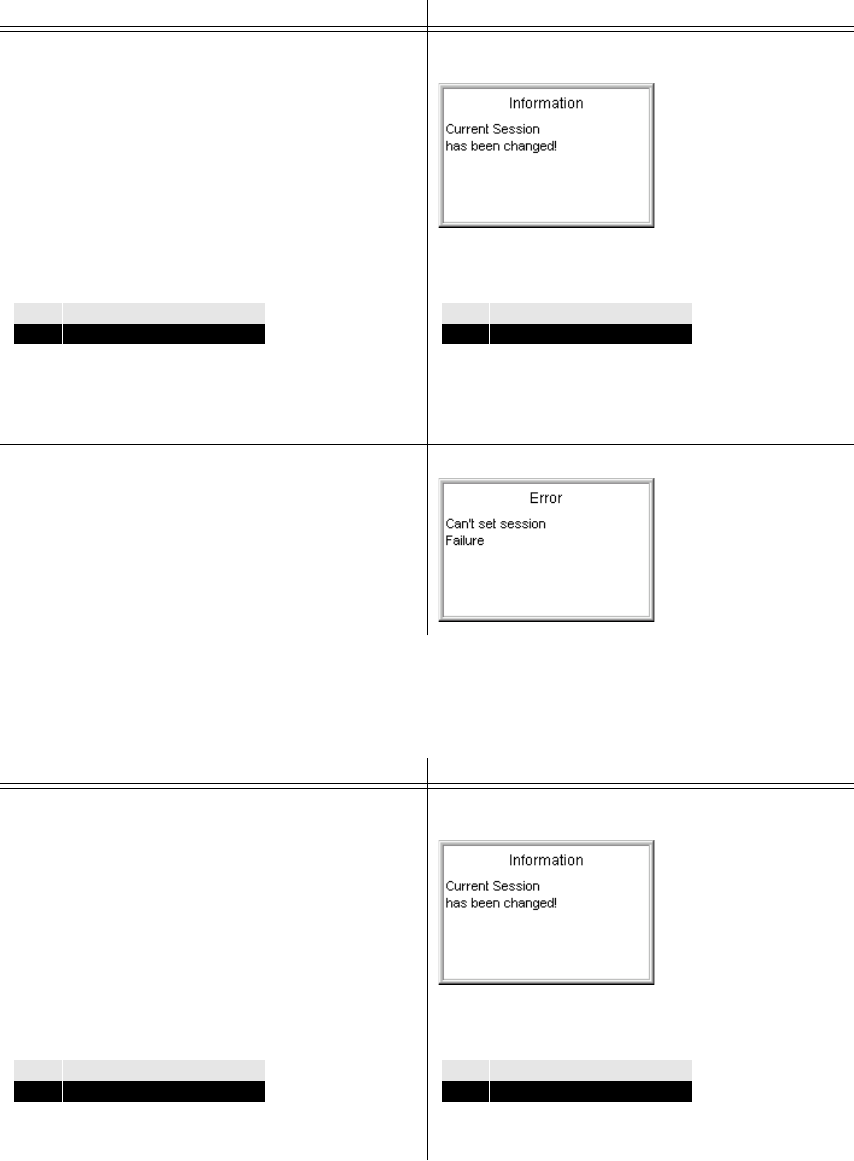
065 75$16&(,9(5 ; $ ; $
Operator’s Manual • Use under Normal Conditions
– 2.32 – 6076.0822.12.02
+Change access level to monitoring
+Press LOCAL key.
GB 4000C, mod. 03 - Unit 55 GB 4000C, mod. 02 - Unit 51
Access level is changed to fixed.
Detail of Menu 030:
Control unit controls transceiver alone and
cannot be interrupted.
→ The following message comes up:
Detail of Menu 030:
When the operator tries to change the COM-
LINE session, the following message comes
up:
GB 4000C, mod. 03 - Unit 55 GB 4000C, mod. 02 - Unit 51
Access level is changed to monitoring.
Detail of Menu 030:
Control unit can take control any time.
→ The following message comes up:
Detail of Menu 030:
Control unit can take control any time.
CL TYPE SESSION ADR
1SIMPLE FIXED own
CL TYPE SESSION ADR
1SIMPLE FIXED 55
CL TYPE SESSION ADR
1SIMPLE own
CL TYPE SESSION ADR
1SIMPLE 55

065 75$16&(,9(5 ; $ ; $
Operator’s Manual • Use under Normal Conditions
6076.0822.12.02 – 2.33 –
GB 4000C, mod. 03 - Unit 55 GB 4000C, mod. 02 - Unit 51
The following message comes up:
Only monitoring is possible.
Menu 040:
← The operator presses key LOCAL.
Control unit controls transceiver in LOCAL
mode.
Menu 040:
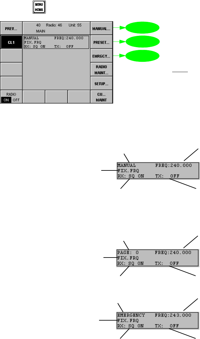
065 75$16&(,9(5 ; $ ; $
Operator’s Manual • Use under Normal Conditions
– 2.34 – 6076.0822.12.02
0HQX0$,1
Starting point: Menu 040
If you come from any other menu,
+ press key and the Menu 040 MAIN (HOME) appears:
Menu 040 shows the current operating status of the radio:
qThe following settings are active:
qDepending on the operation mode further displays are possible:
key MENU HOME
1RWH
6RIWNH\V5$',20$,176(783DQG
&80$,17DUHGHDOWZLWKLQFKDSWHU
for
future
use
0HQX
0HQX
0HQX
Tx/Rx frequency
Transmitter level is OF
F
Receive mode with squelch on
Operation on
fixed frequency
Manual
radio operation
0DQXDO 0RGH
)L[HG)UHTXHQF\
Tx/Rx frequency
Transmitter level is OF
F
Receive mode with squelch on
Operation on
fixed frequency
Preset
page number
3UHVHW 0RGH
)L[HG)UHTXHQF\
Receive mode with squelch on
Operation on
fixed frequency
Emergency
radio operation
(PHUJHQF\ 0RGH
Transmitter level is OFF
Guard frequency
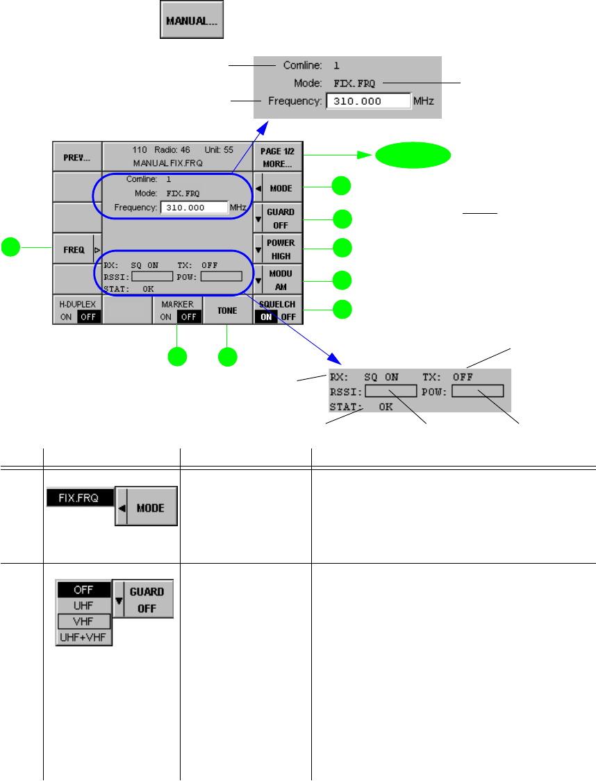
065 75$16&(,9(5 ; $ ; $
Operator’s Manual • Use under Normal Conditions
6076.0822.12.02 – 2.35 –
0HQX3DJH0$18$/),;)54)L[HG)UHTXHQF\
Menu 110 shows the current operating status of the radio. All operation parameters can be se-
lected and edited by means of softkeys.
Starting point: Menu 040 (MAIN)
+Press softkey (1) and the following display appears:
No. Control Action Notes
2 Press softkey
MODE. Selection of radio operating mode (only
FIX. FRQ is possible)
),;)54
The radio performs standard fixed-frequency trans-
mission and reception, without frequency hopping.
3 Press softkey
GUARD.
Select setting.
Selection of the guard receiver AF signal
that in communication mode V/D UNCP is
to be mixed to the main receiver AF signal.
2)) mixer and LED SQL G switched off
8+)AF signal from guard receiver
(UHF channel)
9+) AF signal from guard receiver
(VHF channel)
8+)9+) AF signals from guard receiver
(UHF and/or VHF channel)
Reception of an emergency call is indicated
by illumination of the SQL G LED, as well
as through a status message in the display.
softkey MANUAL...
1RWH
,Q0RQLWRULQJ&RPOLQHVHVVLRQ
RQO\VRIWNH\V35(97,0(
DQG3$*(025(DUH
HQDEOHG
for
future
use
0HQX page 2
Selected Comline
(only 1 is possible) Selected radio opera
-
tion mode
(only FIX. FRQ is pos
-
sible)
Selected frequency
Power indicator
Transmitter level
RSSI indicator
Radio status
Receiver setup

065 75$16&(,9(5 ; $ ; $
Operator’s Manual • Use under Normal Conditions
– 2.36 – 6076.0822.12.02
4 Press softkey
POWER
Select setting.
Selection of transmit power
2)) Tx is switched off
/2: Tx is set to low power
0(',80Tx is set to medium power
+,*+ Tx is set to high power
ÇExact levels in W are defined in Menu
516 (VU TX PARAMETERS).
5 Press softkey
MODU.
Select setting.
Selection of modulation type
$0amplitude modulation
)0frequency modulation
6 Press softkey
SQUELCH. Switches squelch function on or off.
2)) noise without Rx signal, no muting
21Audio signal only if RF signal level is
above squelch level
ÇThe squelch level is set in Menu 515
(VU RX PARAMETERS).
7 Press softkey
TONE. Produces test tone (1 kHz) for test and
monitoring purposes as long as softkey
TONE is pressed.
1RWH
7KLVWRQHLVWUDQVPLWWHGRQWKHVHOHFWHG
UDGLRIUHTXHQF\
8 Press softkey
MARKER. Switches a marker tone on or off, if present.
When a marker tone is present, the softkey
automatically shows ON as the current set-
ting. The marker tone is output via a loud-
speaker or headset. By pressing this
softkey the marker tone is switched off until
the next one occurs.
12 Press softkey
FREQ.
Set value.
Setting of a common frequency for Tx and
Rx operation in the frequency range from
q100 to 512 MHz (VHF/UHF transceiver) or
q108 to 173.9875 MHz (VHF transceiver) or
q225 to 399.9875 MHz (UHF transceiver)
ÇThe stepwidth is selected in Menu
110, page 2 (MANUAL FIX.FRQ).
1RWH
7KHWXQLQJNQREVHWWLQJQHHGVQRFRQILUPD
WLRQZLWK(17
No. Control Action Notes

065 75$16&(,9(5 ; $ ; $
Operator’s Manual • Use under Normal Conditions
6076.0822.12.02 – 2.37 –
0HQX3DJH0$18$/),;)54)L[HG)UHTXHQF\
Starting point: Menu 110, page 1
+Press softkey (1) and the following display appears:
No. Control Action Notes
2 See chapter 2.5.6, softkey 2.
6 Press softkey
CLIPPER. Switches clipper function on or off.
(Noise reduction function only for receiver
in AM mode)
ÇThe CLIPPER level is selected in
Menu 515 (VU RX PARAMETERS).
7 See chapter 2.5.6, softkey 7.
8 See chapter 2.5.6, softkey 8.
11 Press softkey
COMM.
Select setting.
Example: Selection of a pre-defined com-
munication mode, without device mapping
(see also chapter 3):
9'81&3
Voice/Data unciphered (not encrypted)
•Audio line NB1
•Keyline PTT_1L / PTT_2L
:%$1$/2*
for wideband data transmission up to 16 kbps (base-
band)
•Audio line WB2
•Keyline PTT_1L / PTT_2L
softkey PAGE 1/2 MORE...
1RWH
,Q0RQLWRULQJ&RPOLQHVHVVLRQ
RQO\VRIWNH\V35(9DQG
3$*(025(DUH
HQDEOHG
no
function
0HQX page 1

065 75$16&(,9(5 ; $ ; $
Operator’s Manual • Use under Normal Conditions
– 2.38 – 6076.0822.12.02
12 Press softkey
CHAN SP.
Select value.
Selection of the channel spacing value
The channel spacing of 8.33 kHz is only
available in the frequency range from
118 MHz to 144 MHz.
8.33 kHz and 25 kHz are used for civil Air
Traffic Control (ATC) in AM modulation.
25 kHz is standard in UHF band.
13 Press softkey TX
OFFS.
Select value.
Selection of the Tx offset value
Tx offset is used for ATC purposes. Softkey
TX OFFS is enabled in the frequency range
from 118 MHz to 144 MHz.
Tx offset is enabled with 25-kHz channel
spacing.
Tx offset selection is only available with AM
modulation.
1RWH
$Q\FKDQJHRIWKH7[RIIVHWZLOORQO\WDNHHI
IHFWZKHQWKHWUDQVPLWWHULVQH[WNH\HG
14 Press softkey
AF AGC. Switches AF AGC function on or off.
The AGC controls the volume at the AF out-
put for headphones and loudspeaker to a
constant value.
AGC = Automatic Gain Control
(of audio frequency)
No. Control Action Notes

065 75$16&(,9(5 ; $ ; $
Operator’s Manual • Use under Normal Conditions
6076.0822.12.02 – 2.39 –
0HQX3DJH86(535(6(7),;)54)L[HG)UHTXHQF\
The PRESET menu is used for operation with the presettings stored in a PRESET PAGE. A
few of the pre-defined values of the PRESET PAGE can also be edited and the new value can
be stored.
Starting point: Menu 040 (MAIN)
+Press softkey (2) and the following display appears:
No. Control Action Notes
2 Press softkey
MODE. Selection of radio operating mode (only
FIX. FRQ is possible)
),;)54
The radio performs standard fixed-frequency trans-
mission and reception, without frequency hopping.
softkey PRESET...
page 2
0HQX
Power indicator
Transmitter leve
l
RSSI indicator
Radio status
Receiver setup
Selected Comline
(only 1 is possible)
Selected radio opera-
tion mode
(only FIX. FRQ is possi-
ble) Selected frequency
Selected preset page
Current
communication
mode
1RWH
,Q0RQLWRULQJ&RPOLQHVHVVLRQRQO\
VRIWNH\V35(97,0(DQG
3$*(025(DUHHQDEOHG

065 75$16&(,9(5 ; $ ; $
Operator’s Manual • Use under Normal Conditions
– 2.40 – 6076.0822.12.02
3 Press softkey
GUARD.
Select setting.
Selection of the guard receiver AF signal
that in communication mode V/D UNCP is
to be mixed to the main receiver AF signal.
2))mixer and LED SQL G switched off
8+)AF signal from guard receiver
(UHF channel)
9+)AF signal from guard receiver
(VHF channel)
8+)9+)AF signals from guard receiver
(UHF and/or VHF channel)
Reception of an emergency call is indicated
by illumination of the SQL G LED, as well
as through a status message in the display.
4 Press softkey
POWER.
Select setting.
Selection of transmit power
2))Tx is switched off
/2: Tx is set to low power
0(',80Tx is set to medium power
+,*+ Tx is set to high power
ÇExact levels in W are defined in Menu
516 (VU TX PARAMETERS).
5 Press softkey
MODU.
Select setting.
Selection of modulation type
$0amplitude modulation
)0frequency modulation
6 Press softkey
SQUELCH. Switches the squelch function on or off
2)) noise without Rx signal, no muting
21Audio signal only if RF signal level is
above squelch level
ÇThe squelch level is set in Menu 515
(VU RX PARAMETERS).
7 Press softkey
TONE. Produces test tone (1 kHz) for test and
monitoring purposes as long as softkey
TONE is pressed.
1RWH
7KLVWRQHLVWUDQVPLWWHGRQWKH
VHOHFWHGUDGLRIUHTXHQF\
8 Press softkey
MARKER. Switches a marker tone on or off, if present.
When a marker tone is present, the softkey
automatically shows ON as the current set-
ting. The marker tone is output via a loud-
speaker or headset. By pressing this
softkey the marker tone is switched off until
the next one occurs.
No. Control Action Notes
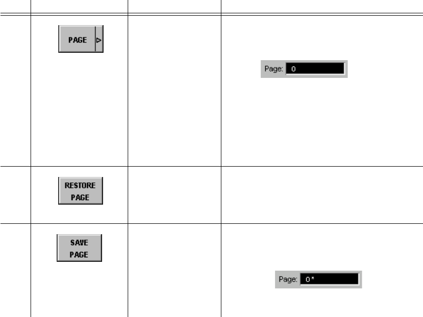
065 75$16&(,9(5 ; $ ; $
Operator’s Manual • Use under Normal Conditions
6076.0822.12.02 – 2.41 –
11 Press softkey
PAGE.
Set value.
The PAGE function is used to load a spe-
cific User Page into the Current Page
range.
The range of values is determined in Menu
610 (PRESET CONFIGURATION).
Preset count 1: 0 to 199
Preset count 2: 0 to 99 (preset = 1)
Preset count 2: 0 to 99 (preset = 2)
For definition of Current Page, User Page
and Loaded Page see chapter 3.
13 Press softkey
RESTORE PAGE. RESTORE PAGE restores the originally
Loaded Page in the User Page area.
Simultaneously the Current page is up-
dated also to the Loaded Page.
14 Press softkey
SAVE PAGE. By using the SAVE PAGE key the content
of the Current Page is stored in the User
Page.
The asterisk signals that User Page and
Loaded Page are no longer identical.
No. Control Action Notes

065 75$16&(,9(5 ; $ ; $
Operator’s Manual • Use under Normal Conditions
– 2.42 – 6076.0822.12.02
0HQX3DJH86(535(6(7),;)54)L[HG)UHTXHQF\
Starting point: Menu 210, page 1
+Press softkey (1) and the following display appears:
No. Control Action Notes
2 See chapter 2.5.8, softkey 2.
6 Press softkey
CLIPPER. Switches clipper function on or off.
(Noise reduction function only for receiver
in AM mode)
ÇThe CLIPPER level is selected in
Menu 515 (VU RX PARAMETERS).
7 See chapter 2.5.8, softkey 7.
8 See chapter 2.5.8, softkey 8.
11 See chapter 2.5.8, softkey 11.
page 1
1RWH
,Q0RQLWRULQJ&RPOLQHVHVVLRQ
RQO\VRIWNH\V35(9DQG3$*(
025(DUHHQDEOHG
0HQX
Current
communication
mode
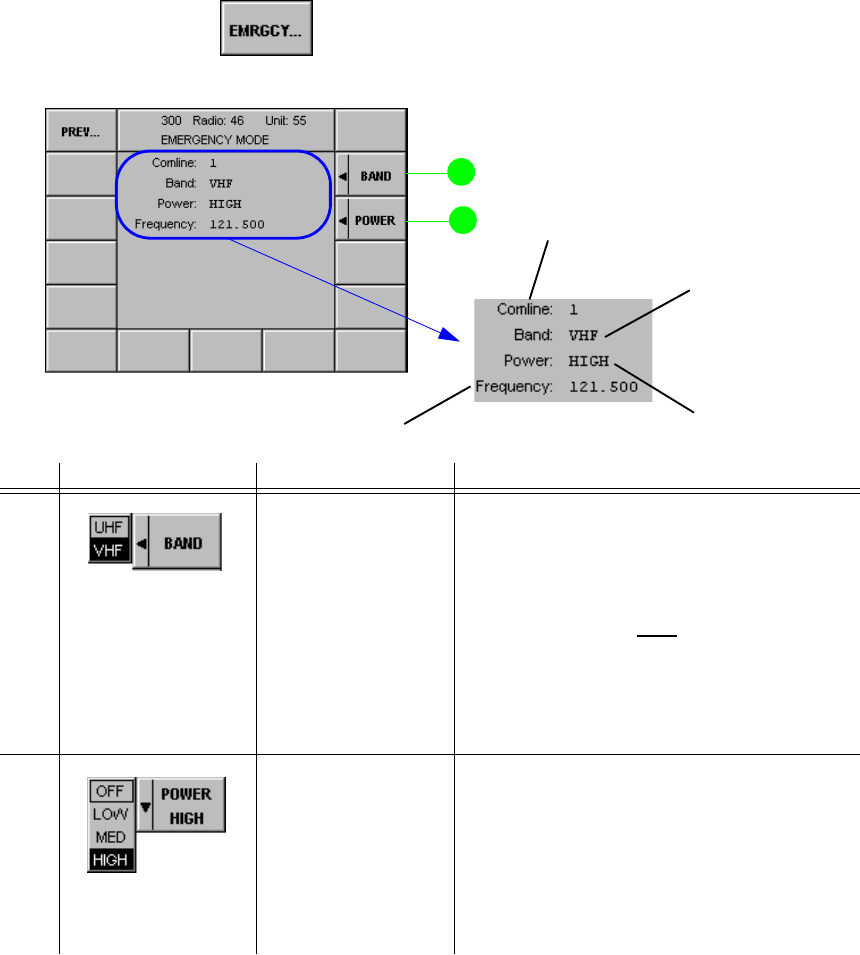
065 75$16&(,9(5 ; $ ; $
Operator’s Manual • Use under Normal Conditions
6076.0822.12.02 – 2.43 / 2.44 –
0HQX(0(5*(1&<02'(
In the EMERGENCY menu, frequency band and transmit power for making an emergency call
can be selected. Reception of an emergency call is indicated by illumination of the SQL G LED,
as well as through a status message in the display. When the operator then changes to the
EMERGENCY menu, that frequency where the call was received on will be automatically set.
Then the operator only has to press the PTT key to answer the emergency call. Depending on
the configuration in Menu 575 (FRONTPANEL AUDIO SOURCE), the emergency call will also
be made audible via the loudspeaker. Softkey GUARD (see Menu 110, page 1 (MANUAL
FIX.FRQ) and Menu 210, page 1 (USER PRESET FIX.FRQ)) is used to select the guard re-
ceiver AF signal that in communication mode V/D UNCP is to be mixed to the main receiver AF
signal on the Comline.
Starting point: Menu 040 (MAIN)
+Press softkey (3)
qThe following display appears:
No. Control Action Notes
2 Press softkey
BAND to select the
required band.
Tunes to emergency frequency of transmit-
ter (VHF or UHF):
VHF = 121.500 MHz
UHF = 243.000 MHz
1RWH
:KHQWKHUDGLRUHFHLYHVDQHPHUJHQF\FDOOHJRQ
0+]DQGWKHRSHUDWRUWKHQFKDQJHVWR0HQX
WKHIUHTXHQF\RI0+]ZLOOEHWXQHGDX
WRPDWLFDOO\+RZHYHULIWKHRSHUDWRUVWLOOZDQWVWRVH
OHFW0+]WKHQKHRQO\QHHGVWRSUHVV
VRIWNH\%$1'
3 Press softkey
POWER to select
the required power
level.
Selection of emergency transmit power
2)) Tx is switched off
/2: Tx is set to low power
0(',80Tx is set to medium power
+,*+ Tx is set to high power
ÇThe exact levels in W are set in Menu
516 (VU TX PARAMETERS).
Guard receiver band
Selected Comline
Transmit power level
Selected guard frequency

065 75$16&(,9(5 ; $ ; $
Operator’s Manual • Use under Normal Conditions
6076.0822.12.01 – 2.45 / 2.46 –
1) only AM
2) only AM and 118 ≤ f≤ 144 MHz
3) A separate audio line (e.g. NB2) needs to be configured in Menu 560 (AUDIO MAPPING)
4) only with 25-kHz channel spacing
5) A separate audio line (NB1) needs to be configured in Menu 560 (AUDIO MAPPING).
Please note that in this case the AF1 interface cannot be used any more for voice modes.
)LJ )XQFWLRQV5HODWHGWRWKH&RPPXQLFDWLRQ0RGH5[5[7[7[
)XQFWLRQ
&RPPXQLFDWLRQ0RGH
Voice / Data
Unciphered Voice / Data
Ciphered Wideband
Analog Wideband
Digital
Diphase
Wideband
Digital
Baseband
Link 11
Rx Squelch [--- --- --- --- ---
Muting [--- --- --- --- [
X26.13 [[[[[n / a
Rx Guard [[3) [3) [3) [3) [5)
Rx AF AGC [1) --- --- --- --- ---
Rx Clipper [1) --- --- --- --- ---
Rx/Tx Frequency
in MHz XU:
100 ≤ f < 174
XD:
225 ≤ f < 400
XT:
100 ≤ f≤ 512
XU:
100 ≤ f < 174
XD:
225 ≤ f < 400
XT:
100 ≤ f≤ 512
XU:
100 ≤ f < 174
XD:
225 ≤ f < 400
XT:
100 ≤ f≤ 512
XU:
100 ≤ f < 174
XD:
225 ≤ f < 400
XT:
100 ≤ f≤ 512
XU:
100 ≤ f < 174
XD:
225 ≤ f < 400
XT:
100 ≤ f≤ 512
XD = XT:
225 ≤ f < 400
Rx/Tx Modulation
(AM / FM) [[[[[FM
Rx/Tx Channel
Spacing
in kHz
8.33 2)
12.5
25.0
12.5
25.0 12.5
25.00 12.5
25.0 12.5
25.0 25.0
Tx Power [[[[[[
Tx Tone [--- --- --- --- ---
Tx TX Offset [4) --- --- --- --- ---

065 75$16&(,9(5 ; $ ; $
Operator’s Manual • Use under Normal Conditions
6076.0822.12.01 - 2.47 / 2.48 -
)LJ 065 7UDQVFHLYHU; $; $0HQX2YHUYLHZ
WELCOME 000 SYSTEM
010 CONNECT
020 COMLINE SESSION 030 RADIO SESSION
040 MAIN/MENU HOME 100 MANUAL 110 MANUAL FIX.FRQ (fixed frequency)
200 PRESET 210 USER PRESET FIX.FRQ (fixed frequency)
300 EMERGENCY
400 RADIO MAINTENANCE Page 1/2 405 RADIO IBIT RESULTS 406 RADIO IBIT DETAILS
410 RADIO CBIT RESULTS 411 RADIO CBIT DETAILS
415 RADIO INVENTORY 416 RADIO INVENTORY DETAILS
420 RADIO ERROR LIST 421 RADIO ERROR DETAILS
425 RADIO CONTROL PORT
435 RADIO ADDRESS LIST 436 RADIO ADDRESS ROUTE
440 RADIO TIME
Page 2/2 505 RADIO OPTIONS 506 SET OPTIONS
510 RADIO MODULES 511 PLATFORM PARAMETERS
512 AFI PARAMETERS
515 VU RX PARAMETERS
516 VU TX PARAMETERS
517 VU SYNT PARAMETERS
535 SPLIT SITE DEFINITION
550 PTT COMLINE MAPPING
560 AUDIO MAPPING
565 DEVICE MAPPING
570 SQUELCH POLARITY
575 FRONTPANEL AUDIO SOURCE
580 MARKER CONTROL
600 RADIO SETUP 610 PRESET CONFIGURATION
620 LOADED PRESET PAGE PARAMS 710 EDIT PRESET PAGE FIX.FRQ
800 CU MAINTENANCE 805 CU IBIT RESULTS 806 CU IBIT DETAILS
807 KEYBOARD TEST
810 CU CBIT RESULTS 811 CU CBIT DETAILS
815 CU INVENTORY 816 CU INVENTORY DETAILS
820 CU ERROR LIST 821 CU ERROR DETAILS
835 CU ADDRESS LIST 836 CU ADDRESS ROUTE
840 DISPLAY PARAMS
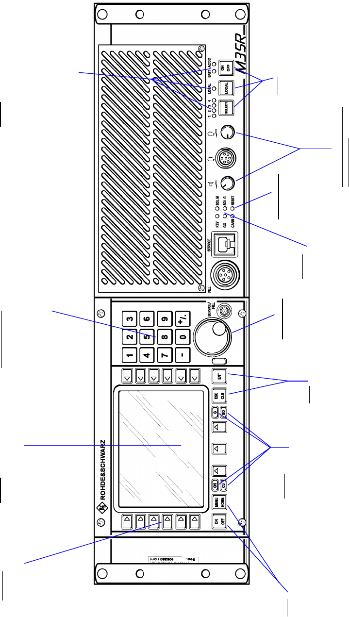
065 75$16&(,9(5 ; $ ; $
Operator’s Manual • Use under Normal Conditions
6076.0822.12.01 – 2.49 / 2.50 –
)LJ 0657UDQVFHLYHU; $&RQWURO DQG'LVSOD\ (OHPHQWV
7XQLQJNQRE
• Tuning values
• Selecting menus
/RXGVSHDNHUKHDGSKRQH
YROXPHFRQWURO
/RZYROXPH
Control turned fully
counter-clockwise
)XOOYROXPH
Control turned fully clockwise
VRIWNH\V
.H\V
(17
• Confirming entries
• Initiating processes
(6&&/5
• Deleting entries
• Aborting processes
.H\V
6(/(&7
Selecting communication line
1 (2 to 4 disabled) = Rx and /
or GRx signal
/2&$/
Selecting local / remote
operation (toggle function)
212))
Switching transceiver
on or off (toggle function)
/('RQ
.(<
Key system on
*2
Radio ok
&$55
Carrier activated
64/0
Squelch main receiver active
64/*
Squelch guard receiver active
/('RQ
21
Control unit is on
&8
Control unit ok
*
Squelch guard receiver active
*2
Radio ok
.H\V
212))
• ON: switching radio ON
• OFF: switching only control unit
off
0(18+20(
Switching to start menu 040
5(6(7EXWWRQ
Resetting the trans-
ceiver
1XPHULFDONH\SDG
,QSXWRI
• Numerical values
• Decimal point
.H\
• Incrementing or decrementing selection
'LVSOD\
• Display of menus
• Display of menu-dependent softkey
functions
6RIWNH\V
Selecting menu-dependent
functions
/('RQ
WR
Communication line selected (2 to 4 disabled)
/2&$/
Local operation selected
%$77
Battery operation
$&'&
AC / DC operation
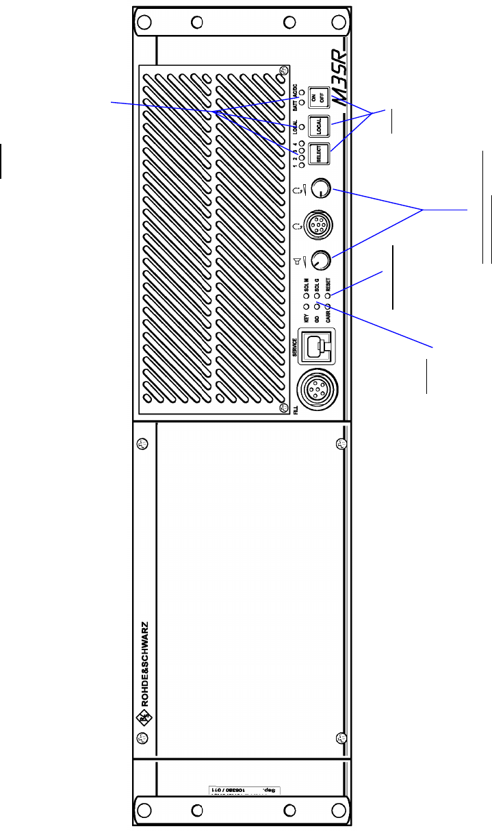
065 75$16&(,9(5 ; $ ; $
Operator’s Manual • Use under Normal Conditions
6076.0822.12.01 – 2.51 / 2.52 –
)LJ 065 7UDQVFHLYHU; $&RQWURO DQG'LVSOD\ (OHPHQWV
/RXGVSHDNHUKHDGSKRQH
YROXPHFRQWURO
/RZYROXPH
Control turned fully
counter-clockwise
)XOOYROXPH
Control turned fully clockwise
VRIWNH\V
.H\V
6(/(&7
Selecting communication line
1 (2 to 4 disabled) = Rx and /
or GRx signal
/2&$/
no function
212))
Switching transceiver
on or off (toggle function)
/('RQ
.(<
Key system on
*2
Radio ok
&$55
Carrier activated
64/0
Squelch main receiver active
64/*
Squelch guard receiver active
5(6(7EXWWRQ
Resetting the trans-
ceiver
/('RQ
WR
Communication line selected (2 to 4 disabled)
/2&$/
Local operation selected
%$77
Battery operation
$&'&
AC / DC operation
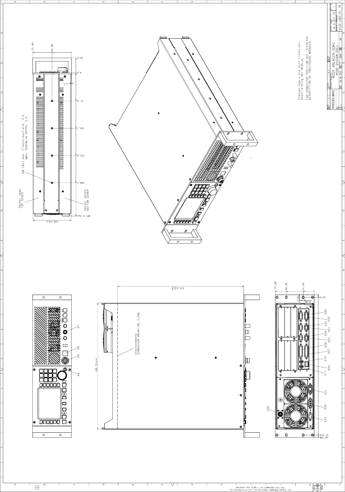

065 75$16&(,9(5 ; $ ; $
Operator’s Manual • Use under Special Conditions
6076.0822.12.01 – 3.1 –
8VHXQGHU6SHFLDO &RQGLWLRQV
1RWH
$OOVHWWLQJVDUHWREHFDUULHGRXWE\TXDOLILHGSHUVRQDOV\VWHPDGPLQLVWUDWRURQO\
,QWURGXFWLRQ
This chapter provides information concerning
qIntroduction to Communication Modes, Resources and External Devices
qConfiguration Examples
- Voice / Data Unciphered
- Wideband Analog
- Wideband Digital
- Link 11 (CLEW)
- Voice / Data Ciphered
qGuard Receiver
qPreset Pages
qPIN Numbers
qConfiguration
- Menu SYSTEM
- Menu RADIO SESSION
- Menu RADIO MAINTENANCE
- Menu Radio SETUP
- Menu CU MAINTENANCE

065 75$16&(,9(5 ; $ ; $
Operator’s Manual • Use under Special Conditions
– 3.2 – 6076.0822.12.01
,QWURGXFWLRQWR&RPPXQLFDWLRQ0RGHV5HVRXUFHVDQG
([WHUQDO'HYLFHV
The following diagram illustrates the relationship between Option Codes, Radio Modes, Exter-
nal Devices, Resources and Communication Modes:
•Option Codes: code to select functionality of radio software
•Radio Modes: type of radio communication
•Communication Mode: method for voice/data transmission
•Resources: audio and PTT interfaces between radio and external devices
•External Devices: type of data terminal equipment that can be connected at the audio in-
terface
•Comline: interface between Rx / Tx functional unit (radio modules) and resources.
)LJ 2YHUYLHZ
7KHUDGLRPRGHGH
WHUPLQHVWKHDYDLOD
EOHFKRLFHRI
FRPPXQLFDWLRQ
PRGHV
2QFHD&RPOLQHLVDV
VLJQHGWRDGHYLFHE\
GHYLFHPDSSLQJWKH
UHVRXUFHVDOVRQHHG
WREHILUPO\DVVLJQHG
WRWKHGHYLFH
2QFHD&RPOLQHLVDV
VLJQHGWRDGHYLFHE\
GHYLFHPDSSLQJIXU
WKHUFRPPXQLFDWLRQ
PRGHVZLOOEHFRPH
DYDLODEOH
:KHQRSWLRQFRGHV
DUHHQWHUHGIXUWKHU
FRPPXQLFDWLRQ
PRGHVZLOOEHFRPH
DYDLODEOH
9LDWKHFRPPXQLFD
WLRQPRGHWKHUH
VRXUFHVVHOHFWHGE\
377DQGDXGLRPDS
SLQJDUHDFWLYDWHG
:KHQRSWLRQFRGHV
DUHHQWHUHGIXUWKHU
UDGLRPRGHVZLOOEH
FRPHDYDLODEOH
1RWH
(DFKUHVRXUFHFDQEH
DVVLJQHGRQO\RQFH
*) basic
External Devices
Cipher Unit KY58
Digital data terminal
Link 11 data terminal
...
Radio Modes
FIX.FRQ *)
...
Communication Modes
Voice / Data unciphered *)
Wideband analog *)
Wideband digital (baseband)
Wideband digital (diphase)
Voice / Data ciphered
Link 11
...
Resources
Audio lines
Wideband 1 *)
Wideband 2 *)
Narrowband 1 *)
Narrowband 2 *)
...
Keylines
PTT_1 *)
PTT_2 *)
PTT_1L *)
PTT_2L *)
...
Option Codes
Link 11
...

065 75$16&(,9(5 ; $ ; $
Operator’s Manual • Use under Special Conditions
6076.0822.12.01 – 3.3 –
&RPPXQLFDWLRQ0RGHV
Depending on the option codes, the external devices connected at the Comline and the cur-
rently active radio mode, one or several of the following communication modes are available:
qVoice / Data Unciphered (V/D UNCP):
The communication mode V/D UNCP is used for narrowband AM and FM voice commu-
nication. The keyline selected by PTT mapping is used. Narrowband audio lines NB1 and
NB2 are available. Audio line NB1 should be used by preference.
qWideband Analog (WB ANALOG)
The communication mode WB ANALOG is used for wideband AM and FM communica-
tion with analog data terminals (only baseband). The keyline selected by PTT mapping
is used. Wideband audio lines WB1 and WB2 are available. Audio line WB2 should be
used by preference.
qWideband Digital Baseband (WB DIGITAL BB) and
Wideband Digital Diphase (WB DIGTAL DP)
The communication modes WB DIGITAL are used for data communication (ASK, FSK)
with digital data terminals (baseband and diphase). Carrier activation for transmission is
carried out via keyline PTT_1, and the digital data are transmitted via wideband audio line
WB1.
qLink 11 (LINK 11)
The communication mode LINK 11 is used for data communication with Link 11 data ter-
minals. Carrier activation for transmission is carried out via keyline PTT_2, and the data
are transmitted via narrowband audio line NB2.
qVoice / Data Ciphered (V/D CP)
The voice encrypted by Cipher Unit KY 58 is transmitted via wideband audio line WB1.
Carrier activation for transmission is carried out via keyline PTT_1L. The KY 58 and the
M3SR Transceiver are interconnected via the following signals:
The following table illustrates how the radio operation mode is related to the communication
mode:
1RWH
:KHQFKDQJLQJWRDGLIIHUHQWFRPPXQLFDWLRQPRGHHJLQ0HQX0$18$/),;)54IXU
WKHUSDUDPHWHUVPD\EHFKDQJHGDXWRPDWLFDOO\:KHQFKDQJLQJIURP9RLFH'DWD8QFLSKHUHG
PRGXODWLRQPRGH$0FKDQQHOVSDFLQJN+]WR/LQNPRGXODWLRQPRGH)0DQGFKDQ
QHOVSDFLQJRIN+]ZLOOEHVHW+RZHYHUFKDQJLQJEDFNWR9RLFH'DWD8QFLSKHUHGZLOOQRW
UHHVWDEOLVKWKHLQLWLDOVHWWLQJVRIPRGXODWLRQPRGHDQGFKDQQHOVSDFLQJ
•CGC (cipher ground control) •BB/DP (baseband / diphase)
•DPTT (delayed PTT) •ZEROIZE
•PT/CT (plain text / cipher text)
Radio operation
mode
Communication mode
V/D UNCP WB
ANALOG
WB
DIGITAL BB
WB
DIGITAL DP
LINK11 V/D CP
FIX.FRQ [[[[[[
065 75$16&(,9(5 ; $ ; $
Operator’s Manual • Use under Special Conditions
– 3.4 – 6076.0822.12.01
5HVRXUFHV
The Audio Frequency Interface (part of Radio Basis KR 4400) provides the following resources:
qfour keylines
- PTT_1L (contact X26.10)
- PTT_1 (contact X26.18)
- PTT_2L (contact X25.10)
- PTT_2 (contact X25.18)
qfour audio lines (narrowband, wideband)
- NB1 (contacts: Tx = X26.1 and .2; Rx = X26.3 and .4)
- NB2 (contacts: Tx = X25.1 and .2; Rx = X25.3 and .4)
- WB1 (contacts: Tx = X26.6 and .7; Rx = X26.8 and .9)
- WB2 (contacts: Tx = X25.6 and .7; Rx = X25.8 and .9)
Resources are activated in Menu 550 (PTT COMLINE MAPPING) for keylines and in Menu 560
(AUDIO MAPPING) for audio lines. Please note that each resource can be assigned only once.
That means that if for instance the resource PTT 1L is assigned to device A, it cannot be as-
signed to device B at the same time.
Keylines may also be defined to be low or high-active.

065 75$16&(,9(5 ; $ ; $
Operator’s Manual • Use under Special Conditions
6076.0822.12.01 – 3.5 –
([WHUQDO'HYLFHV
A great variety of external devices may be connected to the M3SR Transceiver. This also
includes cipher units, digital and Link 11 data terminals. Before external devices can be used,
however, each of them needs to be connected to the Comline. This is done in Menu 565
(DEVICE MAPPING). A Comline is a group of modules within the radio (see also Menu 510
(RADIO MODULES)). Once the device is linked to the Comline, further communication modes
are available for use (see table below).
For the basic communication modes V/D UNCP and WB ANALOG, device mapping is not im-
plemented. Resources are assigned via Menus 550 (PTT COMLINE MAPPING) and 560 (PTT
MAPPING).
Resource assignment to a device connected to the Comline is carried out automatically (see
table below).
Consequently, not all resources are available for the basic communication modes V/D UNCP
and WB ANALOG. The table shows that simultaneous connection of a cipher unit and a digital
modem (SYNC WB DATA) is impossible because both devices need resource WB1.
Once the external devices are linked to the Comline, the operator can select the
communication mode he wants to communicate in by pressing softkey COMM in Menu 110,
page 2 (MANUAL FIX.FRQ).
External Device Comline
Communication mode
V/D UNCP WB
ANALOG
WB
DIGITAL
BB
WB
DIGITAL
DP
LINK11 V/D CP
no external device required CL1 [[
Cipher Unit KY58 CL1 [[ [
Link 11 data terminal CL1 [[ [
Digital data terminal CL1 [[[[
Communication
Mode Comline Keylines Audio Lines External
Device
Mapping
PLL_1L PTT_1 PTT_2L PTT_2 NB1 WB1 NB2 WB2
V/D UNCP CL1 according to PTT Mapping [[
V/D UNCP
CL1 [
[
&LSKHUXQLW
V/D CP [
WB ANALOG CL1 according to PTT Mapping [ [ QRPDSSLQJ
WB DIGITAL BB CL1 [ [ 'LJLWDOGDWDWHU
PLQDO
WB DIGITAL DP CL1 [ [
LINK 11 CL1 [ [ /LQNGDWD
WHUPLQDO

065 75$16&(,9(5 ; $ ; $
Operator’s Manual • Use under Special Conditions
– 3.6 – 6076.0822.12.01
&RQILJXUDWLRQ([DPSOHV
9RLFH'DWD8QFLSKHUHG
1RWH
1RGHYLFHKDVEHHQOLQNHGWRWKH&RPOLQHLQ0HQX'(9,&(0$33,1*
Voice transmission shall take place via narrowband audio line NB1 and carrier activation via
keyline PTT_1L (low-active). Modulation is in AM or FM.
Communication
Mode Comline Keylines Audio Lines External
Device
PLL_1L PTT_1 PTT_2L PTT_2 NB1 WB1 NB2 WB2
V/D UNCP CL1 x [
Audio System
X26
.1
.2
.3
.4
.10
.11
.12
.13
.20
M3SR Transceiver
AF Tx A NB
AF Tx B NB
AF Rx A NB
AF Rx B NB
PTT_1L
AGC (LSB)
AGC (MSB)
Squelch
Carrier
Starting point: Menu 040 (MAIN)
1. Press softkey
Menu 400 (RADIO MAINTENANCE)
2. Enter maintenance PIN by using the
numerical keypad, then press
ENTER.
3. Press softkeys
Menu 560 (AUDIO MAPPING)
4. Select audio lines NB1 by using the
tuning knob.
5. Press softkey
6. Select source CL1 by using the tuning
knob, then press ENTER.
7. Press softkeys
Menu 550 (PTT COMLINE MAPPING)
8. Select keyline PTT_1L by using the
tuning knob.
9. Press softkey
10. Select Comline CL1 by using the tun-
ing knob, then press ENTER.
11. Press softkey to set the
PTT level to low.

065 75$16&(,9(5 ; $ ; $
Operator’s Manual • Use under Special Conditions
6076.0822.12.01 – 3.7 –
12. Press softkeys
Menu 570 (SQUELCH POLARITY)
13. Select squelch SQ COMLINE 1 by us-
ing the tuning knob.
14. Press softkey to set the
squelch level to low.
15. Press softkeys
Menu 575
(FRONTPANEL AUDIO SOURCE)
16. Select audio source 1 by using the
tuning knob.
17. Press softkey
18. Select source CL1 by using the tuning
knob.
19. Press softkeys
Menu 510 (RADIO MODULES)
20. Press softkey
21. Select module audio interface by us-
ing the tuning knob.
22. Press softkey
Menu 512 (AFI PARAMETERS)
23. Press softkey
24. Select audio line NB1 by using the
tuning knob.
25. Press softkey
26. Enter a new TX LEVEL by using the
numerical keypad, then press
ENTER.
Range: -15 dB to 0 dB, if TX-ALC = ON
27. Press softkey
28. Enter a new RX LEVEL by using the
numerical keypad, then press
ENTER.
Range: -20 dB to +10 dB
29. Press softkey
30. Enter a new TX ALC ATTACK time by
using the numerical keypad, then
press ENTER.
Range: 10 ms to 100 ms;
30 ms recommended
31. Press softkey
32. Enter a new TX ALC DECAY time by
using the numerical keypad, then
press ENTER.
Range: 100 ms to 2 000 ms;
300 ms recommended
33. Press softkey to switch on
the automatic level control.
34. Press softkeys
35. Enter a new value for SIDETONE
VOLUME by using the numerical key-
pad, then press ENTER.
Range: -25.5 dB to 0 dB
relative to selected audio Rx level
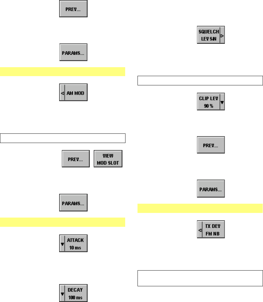
065 75$16&(,9(5 ; $ ; $
Operator’s Manual • Use under Special Conditions
– 3.8 – 6076.0822.12.01
36. Press softkey
37. Select module VU POWER
AMPLIFIER by using the tuning knob.
38. Press softkey
Menu 516 (VU TX PARAMETERS)
39. Press softkey
40. Enter a new modulation depth by us-
ing the numerical keypad, then press
ENTER.
Range: 10% to 99%; 90% recommended
41. Press softkeys
42. Select module VU RX (receiver) by
using the tuning knob.
43. Press softkey
Menu 515 (VU RX PARAMETERS)
44. Press softkey
45. Select a new AF AGC ATTACK time
by using the tuning knob, then press
ENTER.
46. Press softkey
47. Select a new AF AGC DECAY time by
using the tuning knob, then press
ENTER.
48. Press softkey
49. Enter a new threshold by using the
numerical keypad, then press
ENTER.
Range: 6 dB to 20 dB
50. Press softkey
51. Select a new clipper level by using the
tuning knob, then press ENTER.
52. Press softkey
53. Select module VU SYN (synthesizer)
by using the tuning knob.
54. Press softkey
Menu 517 (VU SYN PARAMETERS)
55. Press softkey
56. Enter a new value for TX Deviation
(FM, narrowband) by using the nu-
merical keypad, then press ENTER.
Range: 1 kHz to 20 kHz;
3.5 kHz recommended
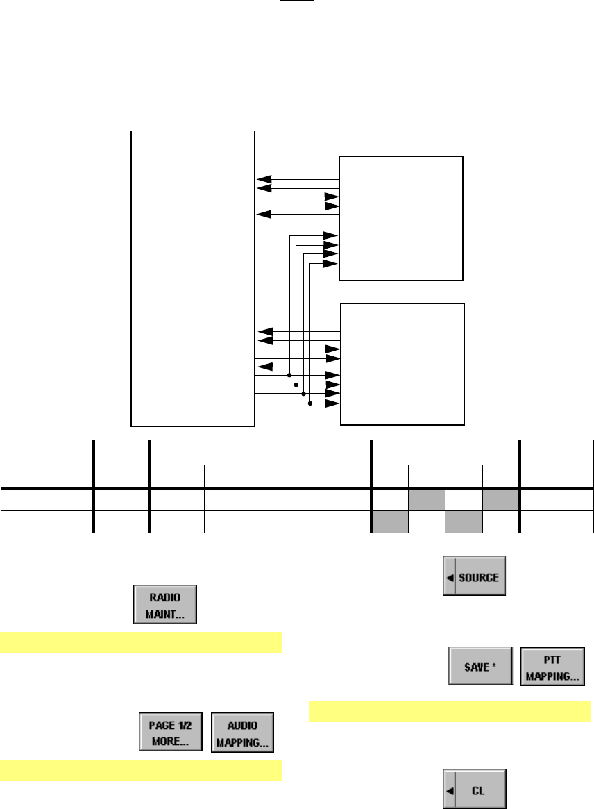
065 75$16&(,9(5 ; $ ; $
Operator’s Manual • Use under Special Conditions
6076.0822.12.01 – 3.9 –
:LGHEDQG$QDORJ
1RWH
1RGHYLFHKDVEHHQOLQNHGWRWKH&RPOLQHLQ0HQX'(9,&(0$33,1*
Voice transmission is to take place via narrowband audio line NB1 and carrier activation via
keyline PTT_1L (low-active). Modulation is in AM or FM (see chapter 3.3.1). In addition, an an-
alog data equipment is connected. Data transmission is to be carried out via wideband audio
line WB2 and carrier activation via keyline PTT_2L (low-active). Modulation is in AM or FM.
Communication
Mode Comline Keylines Audio Lines External
Device
Mapping
PLL_1L PTT_1 PTT_2L PTT_2 NB1 WB1 NB2 WB2
V/D UNCP CL1 x [
WB ANALOG CL1 [ [ QRPDSSLQJ
Analog Data
Equipment
X26
.1
.2
.3
.4
10
.11
.12
.13
.20
M3SR Transceiver
AF Tx A NB
AF Tx B NB
AF Rx A NB
AF Rx B NB
PTT_1L
AGC (LSB)
AGC (MSB)
Squelch
Carrier
X25
.6
.7
.8
.9
.10
AF Tx A WB
AF Tx B WB
AF Rx A WB
AF Rx B WB
PTT_2L
Audio System
no sidetone
no squelch softke
y
no ALC
no muting
Starting point: Menu 040 (MAIN)
1. Press softkey
Menu 400 (RADIO MAINTENANCE)
2. Enter maintenance PIN by using the
numerical keypad, then press
ENTER.
3. Press softkeys
Menu 560 (AUDIO MAPPING)
4. Select audio lines WB2 by using the
tuning knob.
5. Press softkey
6. Select source CL1 by using the tuning
knob, then press ENTER.
7. Press softkeys
Menu 550 (PTT COMLINE MAPPING)
8. Select keyline PTT_2L by using the
tuning knob.
9. Press softkey
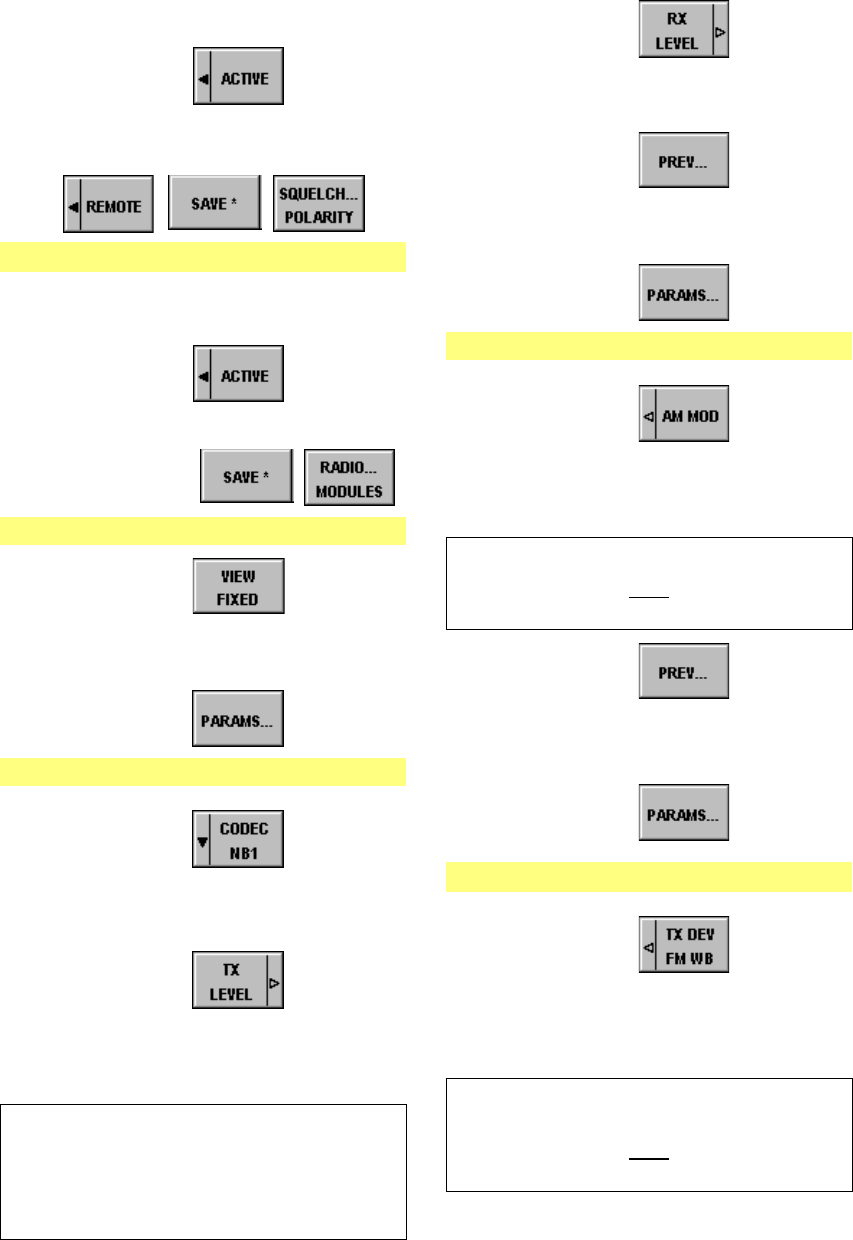
065 75$16&(,9(5 ; $ ; $
Operator’s Manual • Use under Special Conditions
– 3.10 – 6076.0822.12.01
10. Select Comline CL1 by using the tun-
ing knob, then press ENTER.
11. Press softkey to set the
PTT level to low.
12. Press softkeys
Menu 570 (SQUELCH POLARITY)
13. Select squelch SQ COMLINE 1 by us-
ing the tuning knob.
14. Press softkey to set the
squelch level to low.
15. Press softkeys
Menu 510 (RADIO MODULES)
16. Press softkey
17. Select module audio interface by us-
ing the tuning knob.
18. Press softkey
Menu 512 (AFI PARAMETERS)
19. Press softkey
20. Select audio line WB2 by using the
tuning knob.
21. Press softkey
22. Enter a new TX LEVEL by using the
numerical keypad, then press
ENTER.
Range: -3 dB to +15.5 dB
relative to 1.4 Vpp
0 dB = 1.4 Vpp into 600 Ω
-3 dB = 1.0 Vpp into 600 Ω
+15.5 dB = 8.0 Vpp into 600 Ω
23. Press softkey
24. Enter a new RX LEVEL according to
step 22.
25. Press softkey
26. Select module VU POWER
AMPLIFIER by using the tuning knob.
27. Press softkey
Menu 516 (VU TX PARAMETERS)
28. Press softkey
29. Enter a new modulation depth by us-
ing the numerical keypad, then press
ENTER.
Range: 10% to 99%; 90% recommended
1RWH
)UHTXHQF\UDQJH +]WRN+]
30. Press softkey
31. Select module VU SYN (synthesizer)
by using the tuning knob.
32. Press softkey
Menu 517 (VU SYN PARAMETERS)
33. Press softkey
34. Enter a new value for TX Deviation
(FM, wideband) by using the numeri-
cal keypad, then press ENTER.
Range: 1 kHz to 20 kHz;
6.25 kHz recommended
1RWH
)UHTXHQF\UDQJH +]WRN+]

065 75$16&(,9(5 ; $ ; $
Operator’s Manual • Use under Special Conditions
6076.0822.12.01 – 3.11 –
:LGHEDQG'LJLWDO
For voice communication, narrowband audio line NB1 is used, carrier activation is performed
via keyline PTT_1L low-active. Modulation is in AM or FM (see chapter 3.3.1). In addition, a
digital data terminal is connected. Data communication is carried out via wideband audio line
WB1 and carrier activation via keyline PTT_1 low-active. Modulation is in ASK (= amplitude
shift keying) or FSK (= frequency shift keying).
1RWH
,QGLSKDVHPRGHVLJQDOVFDQEHWUDQVPLWWHGZLWKDGDWDUDWHRIXSWRNELWV3OHDVHREVHUYH
WKHORZHUFXWRIIIUHTXHQF\RI+]%HORZWKLVIUHTXHQF\WKHGLJLWDO$0PRGXODWRUZLOOVZLWFK
EDFNWRFDUULHUOHYHO
Communication
Mode Comline Keylines Audio Lines External
Device
Mapping
PLL_1L PTT_1 PTT_2L PTT_2 NB1 WB1 NB2 WB2
V/D UNCP CL1 x [
WB DIGITAL BB CL1 [ [ 'LJLWDO0RGHP
WB DIGITAL DP CL1 [ [
Digital
Data Terminal
X26
.1
.2
.3
.4
.6
.7
.8
.9
10
.11
.12
.13
.18
.20
M3SR Transceiver
AF Tx A NB
AF Tx B NB
AF Rx A NB
AF Rx B NB
AF Tx A WB
AF Tx B WB
AF Rx A WB
AF Rx B WB
PTT_1L
AGC (LSB)
AGC (MSB)
Squelch
PTT_1
Carrier
Audio System no squelch softke
y
no muting
Starting point: Menu 040 (MAIN)
1. Press softkey
Menu 400 (RADIO MAINTENANCE)
2. ENTER maintenance PIN by using
the numerical keypad, then press
ENTER.
3. Press softkeys
Menu 565 (DEVICE MAPPING)
4. Select SYNC WB DATA by using the
tuning knob.
5. Press softkey
6. Select Comline 1 by using the tuning
knob, then press ENTER.
7. Press softkey
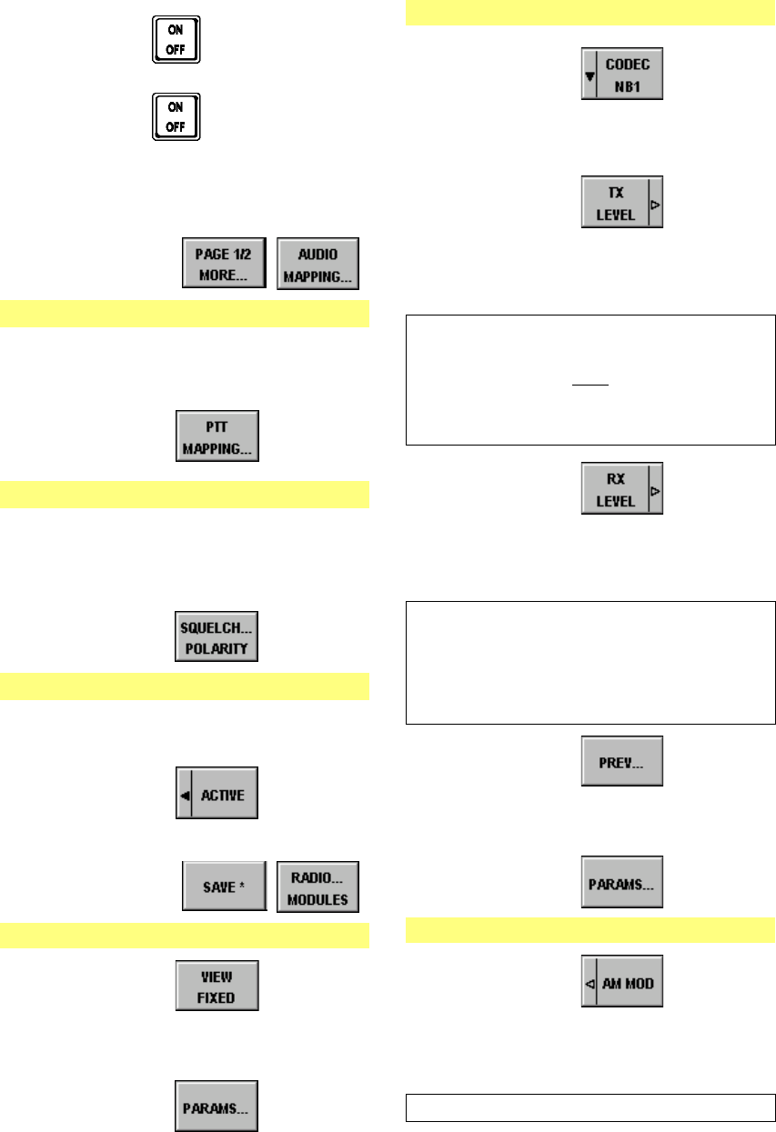
065 75$16&(,9(5 ; $ ; $
Operator’s Manual • Use under Special Conditions
– 3.12 – 6076.0822.12.01
8. Press key (front panel).
9. Press key again.
10. ENTER maintenance PIN by using
the numerical keypad, then press
ENTER.
11. Press softkeys
Menu 560 (AUDIO MAPPING)
12. Check if audio line WB1 is connected
with Comline CL1. If necessary, con-
nect.
13. Press softkey
Menu 550 (PTT COMLINE MAPPING)
14. Check if keyline PTT_1 is connected
with Comline CL1, if it is low-active
and only effective in remote mode. If
necessary, configure.
15. Press softkey
Menu 570 (SQUELCH POLARITY)
16. Select squelch SQ COMLINE 1 by us-
ing the tuning knob.
17. Press softkey to set the
squelch level to low.
18. Press softkeys
Menu 510 (RADIO MODULES)
19. Press softkey
20. Select module audio interface by us-
ing the tuning knob.
21. Press softkey
Menu 512 (AFI PARAMETERS)
22. Press softkey
23. Select audio line WB1 by using the
tuning knob.
24. Press softkey
25. Enter a new TX LEVEL by using the
numerical keypad, then press
ENTER.
Range: -3 dB to +15.5 dB
relative to 1.4 Vpp
1RWH
$SSUR[LPDWLRQWRWKHGLJLWDOLQSXWOHYHOZLOOVXIILFH
7KHVLJQDOZLOOEHGLJLWL]HGE\PHDQVRIDQLQWHUQDO
FRPSDUDWRU
26. Press softkey
27. Enter a new RX LEVEL by using the
numerical keypad, then press
ENTER.
Range: -3 dB to +15.5 dB
relative to 1.4 Vpp
28. Press softkey
29. Select module VU POWER
AMPLIFIER by using the tuning knob.
30. Press softkey
Menu 516 (VU TX PARAMETERS)
31. Press softkey
32. Enter a new modulation depth by us-
ing the numerical keypad, then press
ENTER.
Range: 10% to 99%; 90% recommended
0 dB = 1.4 Vpp into 600 Ω
-3 dB = 1.0 Vpp into 600 Ω
+15.5 dB = 8.0 Vpp into 600 Ω

065 75$16&(,9(5 ; $ ; $
Operator’s Manual • Use under Special Conditions
6076.0822.12.01 – 3.13 –
/LQN&/(:
For voice communication, narrowband audio line NB1 is used, carrier activation is performed
via keyline PTT_1L low-active. Modulation is in AM or FM (see chapter 3.3.1). In addition, a
Link 11 data terminal is connected. Data communication is carried out via narrowband audio
line NB2 and carrier activation via keyline PTT_2 high-active. Modulation is in FM.
Communication
Mode Comline Keylines Audio Lines External
Device
Mapping
PLL_1L PTT_1 PTT_2L PTT_2 NB1 WB1 NB2 WB2
V/D UNCP CL1 x [
LINK 11 CL1 [ [ /LQN'DWD
7HUPLQDO
Link 11 Data
Terminal
X26
.1
.2
.3
.4
.10
.11
.12
.13
.20
M3SR Transceiver
AF Tx A NB
AF Tx B NB
AF Rx A NB
AF Rx B NB
PTT_1L
AGC (LSB)
AGC (MSB)
Squelch
Carrier
Audio System
X25
.1
.2
.3
.4
.18
.21
AF Tx A NB
AF Tx B NB
AF Rx A NB
AF Rx B NB
PTT_2
~LINK11
no sidetone
Starting point: Menu 040 (MAIN)
1. Press softkey
Menu 400 (RADIO MAINTENANCE)
2. ENTER maintenance PIN by using
the numerical keypad, then press
ENTER.
3. Press softkeys
Menu 565 (DEVICE MAPPING)
4. Select LINK 11 by using the tuning
knob.
5. Press softkey
6. Select Comline 1 by using the tuning
knob, then press ENTER.
7. Press softkey
8. Press key (front panel).
9. Press key again.
10. Enter maintenance PIN by using the
numerical keypad, then press
ENTER.
11. Press softkeys
Menu 560 (AUDIO MAPPING)
12. Check if audio line NB2 is connected
with Comline CL1. If necessary, con-
nect.
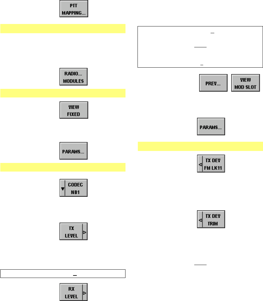
065 75$16&(,9(5 ; $ ; $
Operator’s Manual • Use under Special Conditions
– 3.14 – 6076.0822.12.01
13. Press softkey
Menu 550 (PTT COMLINE MAPPING)
14. Check if keyline PTT_2 is connected
with Comline CL1, if it is high-active
and only effective in remote mode. If
necessary, configure.
15. Press softkey
Menu 510 (RADIO MODULES)
16. Press softkey
17. Select module audio interface by us-
ing the tuning knob.
18. Press softkey
Menu 512 (AFI PARAMETERS)
19. Press softkey
20. Select audio line NB2 by using the
tuning knob.
21. Press softkey
22. Enter a new TX LEVEL by using the
numerical keypad, then press
ENTER.
Range: 0 dB +3 dB
23. Press softkey
24. Enter a new RX LEVEL by using the
numerical keypad, then press
ENTER.
Range: 0 dB +3 dB
(effective level into 600 Ω)
1RWH
:LWKD/LQNWHVWVLJQDORIN+]ZLWKN+]GHYLD
WLRQWKHRXWSXWOHYHOZLOOEHDGMXVWDEOHWR
G%G%P
25. Press softkeys
26. Select module VU SYN (synthesizer)
by using the tuning knob.
27. Press softkey
Menu 517 (VU SYN PARAMETERS)
28. Press softkey
29. Enter a value of 20 kHz for TX Devia-
tion for Link 11 operation by using the
numerical keypad, then press
ENTER.
30. Press softkey
31. Enter a new value for fine tuning of
synthesizer FM modulator by using
the tuning knob, then press ENTER.
1RWH
)LQHWXQLQJIRUN+]GHYLDWLRQWHVWVLJQDON+]VL
QXVRLGDOZLWKHIIHFWLYHOHYHORIG%PLQWRΩ
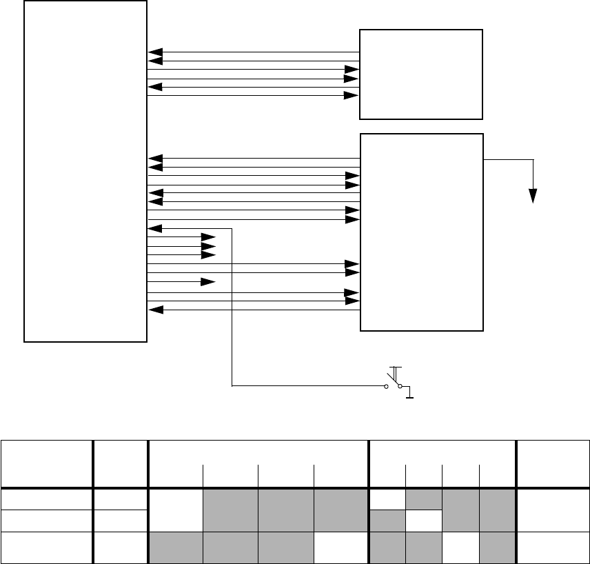
065 75$16&(,9(5 ; $ ; $
Operator’s Manual • Use under Special Conditions
6076.0822.12.01 – 3.15 –
9RLFH'DWD&LSKHUHG
A Cipher Unit KY58 is connected and operated in baseband mode. For voice communication,
narrowband audio line NB1 and wideband audio line WB1 are used, carrier activation is per-
formed via keyline PTT_1L low-active. Modulation is in AM or FM. In addition, a Link 11 data
terminal is connected. Data communication is carried out via narrowband audio line NB2 and
carrier activation via keyline PTT_2 high-active. Modulation is in FM (see chapter 3.3.4).
Communication
Mode Comline Keylines Audio Lines External
Device
Mapping
PLL_1L PTT_1 PTT_2L PTT_2 NB1 WB1 NB2 WB2
V/D UNCP CL1
[
[
&LSKHU8QLW
V/D CP CL1 [
LINK 11 CL1 [ [ /LQN'DWD
7HUPLQDO
Link 11 Data
Terminal
M3SR Transceiver
X25
.1
.2
.3
.4
.18
.21
AF Tx A NB
AF Tx B NB
AF Rx A NB
AF Rx B NB
PTT_2
~LINK11
X26
.1
.2
.3
.4
.6
.7
.8
.9
10
.11
.12
.13
.16
.17
.20
.24
.25
.26
AF Tx A NB
AF Tx B NB
AF Rx A NB
AF Rx B NB
AF Tx A WB
AF Tx B WB
AF Rx A WB
AF Rx B WB
PTT_1L
AGC (LSB)
AGC (MSB)
Squelch
BB/~DP
~DPTT
Carrier
Zeroize
PT/CT
CGC
Cipher Unit KY58
to Audio System
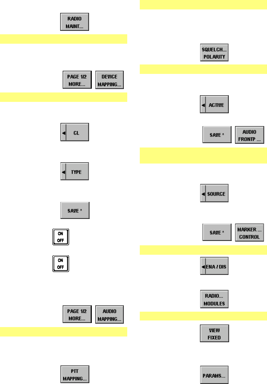
065 75$16&(,9(5 ; $ ; $
Operator’s Manual • Use under Special Conditions
– 3.16 – 6076.0822.12.01
Starting point: Menu 040 (MAIN)
1. Press softkey
Menu 400 (RADIO MAINTENANCE)
2. ENTER maintenance PIN by using
the numerical keypad, then press
ENTER.
3. Press softkeys
Menu 565 (DEVICE MAPPING)
4. Select CIPHER UNIT by using the
tuning knob.
5. Press softkey
6. Select Comline 1 by using the tuning
knob, then press ENTER.
7. Press softkey
8. Select KY58BB or KY58DP by using
the tuning knob, then press ENTER.
9. Press softkey
10. Press key (front panel).
11. Press key again.
12. Enter maintenance PIN by using the
numerical keypad, then press
ENTER.
13. Press softkeys
Menu 560 (AUDIO MAPPING)
14. Check if audio lines NB1 and WB1
are connected with Comline CL1. If
necessary, connect.
15. Press softkey
Menu 550 (PTT COMLINE MAPPING)
16. Check if keyline PTT_1L is connected
with Comline CL1, if it is low-active
and only effective in remote mode. If
necessary, configure.
17. Press softkey
Menu 570 (SQUELCH POLARITY)
18. Select squelch SQ COMLINE 1 by us-
ing the tuning knob.
19. Press softkey to set the
squelch level to low.
20. Press softkeys
Menu 575
(FRONTPANEL AUDIO SOURCE)
21. Select audio source 1 by using the
tuning knob.
22. Press softkey
23. Select source CL1 by using the tuning
knob.
24. Press softkeys
Menu 580 (MARKER CONTROL)
25. Press softkey to enable
plain marker tone.
26. Press softkey
Menu 510 (RADIO MODULES)
27. Press softkey
28. Select module audio interface by us-
ing the tuning knob.
29. Press softkey

065 75$16&(,9(5 ; $ ; $
Operator’s Manual • Use under Special Conditions
6076.0822.12.01 – 3.17 –
Menu 512 (AFI PARAMETERS)
30. Press softkey
31. Select audio line NB1 by using the
tuning knob.
32. Press softkey
33. Enter a new TX LEVEL by using the
numerical keypad, then press
ENTER.
Range: -15 dB to 0 dB, if TX-ALC = ON
34. Press softkey
35. Enter a new RX LEVEL by using the
numerical keypad, then press
ENTER.
Range: -20 dB to +10 dB
36. Press softkey
37. Enter a new TX ALC ATTACK time by
using the numerical keypad, then
press ENTER.
Range: 10 ms to 100 ms;
30 ms recommended
38. Press softkey
39. Enter a new TX ALC DECAY time by
using the numerical keypad, then
press ENTER.
Range: 100 ms to 2 000 ms;
300 ms recommended
40. Press softkey to switch on
the automatic level control.
41. Press softkey
42. Select audio line WB1 by using the
tuning knob.
43. Press softkey
44. Enter a new TX LEVEL by using the
numerical keypad, then press
ENTER.
Range: -3 dB to +15.5 dB
relative to 1.4 Vpp
45. Press softkey
46. Enter a new RX LEVEL according to
step 44.
47. Press softkeys
48. Enter a new value for SIDETONE
VOLUME by using the numerical key-
pad, then press ENTER.
Range: -25.5 dB to 0 dB
relative to selected audio Rx level
49. Press softkey
50. Enter a new value for MARKER
VOLUME according to step 48.
51. Press softkey
52. Select module VU POWER
AMPLIFIER by using the tuning knob.
53. Press softkey
Menu 516 (VU TX PARAMETERS)
54. Press softkey
55. Enter a new modulation depth by us-
ing the numerical keypad, then press
ENTER.
Range: 10% to 99%; 90% recommended
0 dB = 1.4 Vpp into 600 Ω
-3 dB = 1.0 Vpp into 600 Ω
+15.5 dB = 8.0 Vpp into 600 Ω
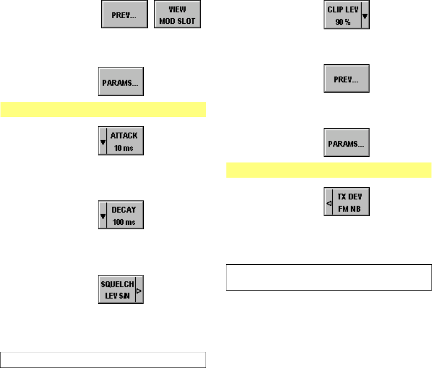
065 75$16&(,9(5 ; $ ; $
Operator’s Manual • Use under Special Conditions
– 3.18 – 6076.0822.12.01
56. Press softkeys
57. Select module VU RX (receiver) by
using the tuning knob.
58. Press softkey
Menu 515 (VU RX PARAMETERS)
59. Press softkey
60. Select a new AF AGC ATTACK time
by using the tuning knob, then press
ENTER.
61. Press softkey
62. Select a new AF AGC DECAY time by
using the tuning knob, then press
ENTER.
63. Press softkey
64. Enter a new threshold by using the
numerical keypad, then press
ENTER.
Range: 6 dB to 20 dB
65. Press softkey
66. Select a new clipper level by using the
tuning knob, then press ENTER.
67. Press softkey
68. Select module VU SYN (synthesizer)
by using the tuning knob.
69. Press softkey
Menu 517 (VU SYN PARAMETERS)
70. Press softkey
71. Enter a new value for TX Deviation
(FM, narrowband) by using the nu-
merical keypad, then press ENTER.
Range: 1 kHz to 20 kHz;
3.5 kHz recommended

065 75$16&(,9(5 ; $ ; $
Operator’s Manual • Use under Special Conditions
6076.0822.12.01 – 3.19 –
*XDUG5HFHLYHU
The guard receiver is a common resource, meaning that it is not assigned to any particular
Comline.
There are two different ways for the guard receiver to be operated.
a) Without audio mapping
Plug the module Guard Receiver ET 4400G into the M3SR Transceiver. No audio map-
ping is necessary.
The guard receiver is only available in communication mode Voice / Data unciphered
(V/D UNCP).
Depending on the selection made by using softkey GUARD (Menus 110 (MANUAL
FIX.FRQ) and 210 (USER PRESET FIX.FRQ)), the guard receiver AF signal is mixed
to the main receiver AF signal.
Depending on the selection made by using softkey GUARD, the LEDs G (Control Unit)
and SQL G (Front Panel), as well as a status message in the display signal an emer-
gency call.
Reception of an emergency call is signalled at contact X26.19 always, irrespective of
the selection made by softkkey GUARD.
The volume of the GRx audio signal is configured in Menu 512 (AFI PARAMETERS).
b) With audio mapping
Audio line NB2 is assigned to the guard receiver via Menu 560 (AUDIO MAPPING).
The guard receiver AF signal is available on audio line NB2 irrespective of the commu-
nication mode and the selection made by softkey GUARD (Menus 110 (MANUAL
FIX.FRQ) and 210 (USER PRESET FIX.FRQ)).
Reception of an emergency call is signalled at contact X26.19 always, irrespective of
the selection made by softkkey GUARD.
The volume of the GRx audio signal is configured in Menu 512 (AFI PARAMETERS).
1RWH
&RPPXQLFDWLRQPRGH/LQNFDQQRWEHXVHGZKHQDXGLROLQH1%LVDVVLJQHGWRWKHJXDUG
UHFHLYHU
065 75$16&(,9(5 ; $ ; $
Operator’s Manual • Use under Special Conditions
– 3.20 – 6076.0822.12.01
3UHVHW3DJH
*HQHUDO
qA Preset Page always consists of two areas:
Fixed Frequency area
EPM area (not used in this application)
qFor the Preset Pages the full choice of functions is available, regardless of the functions
actually supported by the relevant radio. So for example Link 11 communication mode
can be selected, although your radio may not have such functionality.
qA plausibility check will only be performed when the Preset Page is called. So when
Link 11 mode is set in a Preset Page and this page is then called on a radio that does not
support Link 11 functionality, the default (communication mode V/D UNCP) will be acti-
vated instead.
qWhen editing the Preset Pages make sure that matching parameters are selected. For
instance for communication mode Link 11 select modulation type FM.
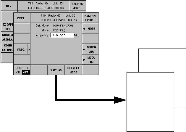
065 75$16&(,9(5 ; $ ; $
Operator’s Manual • Use under Special Conditions
6076.0822.12.01 – 3.21 –
,QWURGXFWLRQWR/RDGHG8VHUDQG&XUUHQW3DJHV
Page storage within the radio is based on a redundancy concept. There are three areas for the
Preset Page to be stored:
qLoaded Page area: pages with factory and / or customer-predefined settings
qUser Page area: copies of Loaded Pages that can be edited
qCurrent Page area: currently used page
/RDGHG3DJH$UHD
Pages with factory and / or customer-predefined settings are referred to as Loaded Pages and
can only be changed by the administrator. Identical copies of the Loaded Pages are used as
basis for User Pages and Current Pages, which can then be edited by the operator as required.
Normally Loaded Pages will be loaded into the radio via the Service and Maintenance Tool
ZS 4400. In some cases, however, it may be necessary to enter these pages manually, which
can be done only by an administrator having the required setup PIN. For editing a Preset Page
an editor (Menu 710 (EDIT PRESET PAGE FIX.FRQ)) is available. Softkey SAVE AS is used
to store the edited Preset Page as Loaded Page and simultaneously as User Page.
)LJ (GLWLQJDQG6WRULQJD/RDGHG3DJH
User Page
12
Loaded Page
12
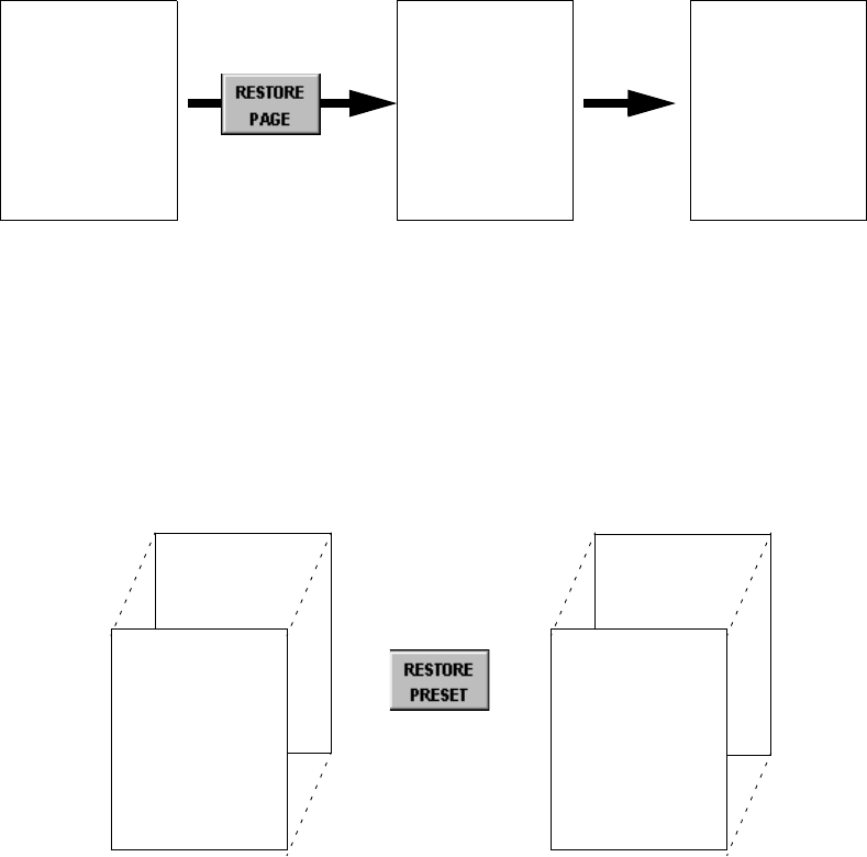
065 75$16&(,9(5 ; $ ; $
Operator’s Manual • Use under Special Conditions
– 3.22 – 6076.0822.12.01
8VHU3DJH$UHD
The User Pages are a copy of the Loaded Pages, which can be edited for ongoing operation.
User Pages can be restored to the Loaded Page settings either individually or globally. In the
figures below any text in italics indicates that this page has been edited.
By pressing softkey RESTORE PAGE (Menu 210 (USER PRESET FIX.FRQ)) a specific User
Page is restored to the relevant Loaded Page setting. Here Restore also has an immediate im-
pact on the Current Page.
)LJ 5HVWRULQJD6SHFLILF8VHU3DJH
By pressing softkey RESTORE PRESET (Menu 610 (PRESET CONFIGURATION)) all User
Pages are restored to the relevant Loaded Page settings. For this no particular User Page
needs to be entered. Here Restore has no impact on the Current Page.
)LJ 5HVWRULQJ$OO8VHU3DJHV
8VHU3DJH
User Page
12
=
Loaded Page
12
Current Page
12
User Page
199
User Page
0
=
Loaded Page
0
User Page
199
8VHU3DJH

065 75$16&(,9(5 ; $ ; $
Operator’s Manual • Use under Special Conditions
6076.0822.12.01 – 3.23 –
&XUUHQW3DJH$UHD
The currently used User Page is the Current Page.
)LJ $FWLYDWLQJD6SHFLILF8VHU3DJH
The Current Page can be edited by the operator in the Preset Page editor (Menu 210 (USER
PRESET FIX.FRQ)). By pressing softkey SAVE PAGE the edited settings can be saved in the
User Page. A User Page modified in this way is marked by an asterisk.
)LJ (GLWLQJDQG6DYLQJD&XUUHQW3DJH
User Page
12
Current Page
12
Current Page
12 *
User Page
12 *
065 75$16&(,9(5 ; $ ; $
Operator’s Manual • Use under Special Conditions
– 3.24 – 6076.0822.12.01
3,11XPEHUV
To protect the radio system from tampering there are two levels of PIN (Personal Identification
Numbers) numbers in force:
qSystem PIN
qUser PINs
System PIN
•The System PIN is used to globally change the User PINs.
•The System PIN is unique and firmly tied to one particular radio. The System PIN is de-
rived from the equipment serial number and can be retrieved any time from the manufac-
turer, if lost.
•The System PIN is intended to be used by service or supervisor staff.
User PINs
The User PINs are required to gain access to the Maintenance and Setup areas of the radio
and also when the operator wants to change from Comline Session to Radio Session. There
are three User PINs for the transceiver and one User PIN for the control unit.
Transceiver
•Radio Maintenance PIN
The Radio Maintenance PIN is used to gain access to the Maintenance area. In the Main-
tenance area it is for instance possible to clear the error list and/or to configure the trans-
ceiver.
•Radio Setup PIN
The Radio Setup PIN is used to gain access to the Setup area. In the Setup area it is
possible to create, modify and/or clear the Preset Pages.
•Radio Session PIN
The Radio Session PIN is used to change from Comline to Radio session. In the Radio
session it is for instance possible to assign the modules to Comline CL1 and to reactivate
the default settings.
Control unit
•CU Maintenance PIN
The CU Maintenance PIN is used to gain access to the control unit Maintenance area. In
the Maintenance area it is for instance possible to clear the error list and/or to configure
the display parameters.
These PIN numbers can be changed by the operator. The default setting (factory setting) of
these PIN numbers is "00000". But please keep in mind: Once changed, the default setting is
no longer valid and cannot be used any more.
Each PIN number to be entered or changed is a five-digit decimal figure.
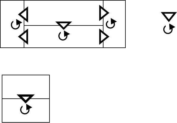
065 75$16&(,9(5 ; $ ; $
Operator’s Manual • Use under Special Conditions
6076.0822.12.01 – 3.25 –
The figure below illustrates when a User PIN needs to be entered and where it can be changed:
The relevant User PIN can be changed in Menu 400 (Radio Maintenance), Menu 600 (Radio
Setup) and Menu 800 (CU Maintenance), respectively.
In addition, the User PINs can be changed globally via Menu 0 (System Menu).
&RPOLQH6HVVLRQ
5DGLR6HVVLRQ
0DLQWHQDQFH
6HWXS
0DLQWHQDQFH
= PIN required
= PIN changeable
2SHUDWLRQ
Control Unit
*)
*) = not yet implemented
Transceiver

065 75$16&(,9(5 ; $ ; $
Operator’s Manual • Use under Special Conditions
– 3.26 – 6076.0822.12.01
&RQILJXUDWLRQ
0HQX6<67(0
In Menu 0 (SYSTEM) the User PINs can be changed globally (for details on PIN numbers refer
to chapter 3.6).
+ Press key and key simultaneously.
qThe following display appears:
No. Control Action Notes
2 Press softkey PIN
RADIO MAINT.
Abort entry.
Entry of new radio maintenance PIN
1. Enter the RADIO SYSTEM PIN number
by using the numerical keypad, then
press ENTER.
2. Enter new MAINT PIN number by using
the numerical keypad, then press
ENTER.
3. Confirm the new MAINT PIN number by
repeating the entry by using the numeri-
cal keypad, then press ENTER.
3 For entry of a new radio setup PIN follow
the same procedure as described for the
radio maintenance PIN (see softkey 2).
keys MENU HOME and ENT
softkey PIN RADIO SETUP

065 75$16&(,9(5 ; $ ; $
Operator’s Manual • Use under Special Conditions
6076.0822.12.01 – 3.27 –
4 For entry of a new radio session PIN fol-
low the same procedure as described for
the radio maintenance PIN (see softkey
2).
14 Press softkey PIN
CU MAINT.
Abort entry.
Entry of new CU maintenance PIN
1. Enter the CU SYSTEM PIN number by
using the numerical keypad, then press
ENTER.
2. Enter new MAINT PIN number by using
the numerical keypad, then press
ENTER.
3. Confirm the new MAINT PIN number by
repeating the entry by using the numeri-
cal keypad, then press
ENTER.
No. Control Action Notes
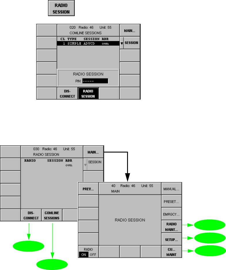
065 75$16&(,9(5 ; $ ; $
Operator’s Manual • Use under Special Conditions
– 3.28 – 6076.0822.12.01
0HQX5$',26(66,21
Changing from Comline session to Radio session is required to
qrestore the default settings (see Appendix A1),
qinstall radio options (Menu 505 (RADIO OPTIONS)),
qconnect a radio module to the Comline (Menu 510 (RADIO MODULES)),
qconfigure split-site operation (Menu 535 (SPLIT SITE DEFINITION))
Starting point: Menu 020 (COMLINE SESSION)
+Press softkey (8) and the following display appears:
+Enter RADIO SESSION PIN number by using the numerical keypad.
+Confirm with ENTER key.
softkey RADIO SESSION
for
future
use
0HQX
0HQX
0HQX
0HQX
0HQX
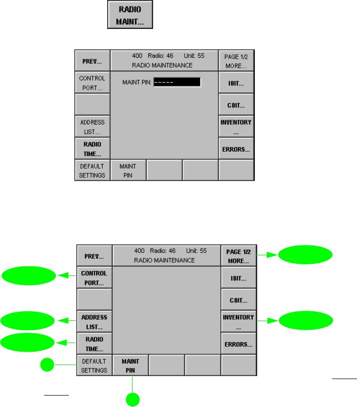
065 75$16&(,9(5 ; $ ; $
Operator’s Manual • Use under Special Conditions
6076.0822.12.01 – 3.29 –
0HQX3DJH5$',20$,17(1$1&(
Via this menu the maintenance functions implemented in the radio are activated. The mainte-
nance functions relate to the assignment of radio resources to Comlines, squelch polarity, in-
ventory report, failure archive and initiation of IBIT functions. Access to some of the
maintenance functions is protected by a PIN (Personal Identification Number), for Inventory,
Errors and Radio Time, however, no PIN is required. Some maintenance functions should only
be activated by trained maintenance staff.
Starting point: Menu 040 (MAIN)
+Press softkey (4) and the following display appears:
+Enter maintenance PIN (5 digits) by using the numerical keypad, then press ENTER.
qThe following display appears:
+Press the relevant softkey to call one of these menus.
softkey RADIO MAINT...
1RWH
,Q5DGLRVHVVLRQ
VRIWNH\'()$8/7
6(77,1*LVHQDEOHG
0HQX
0HQX
page 2
0HQX
0HQX
0HQX
1RWH
6RIWNH\V,%,7&%,7DQG
(55256DUHGHVFULEHGLQ
FKDSWHU
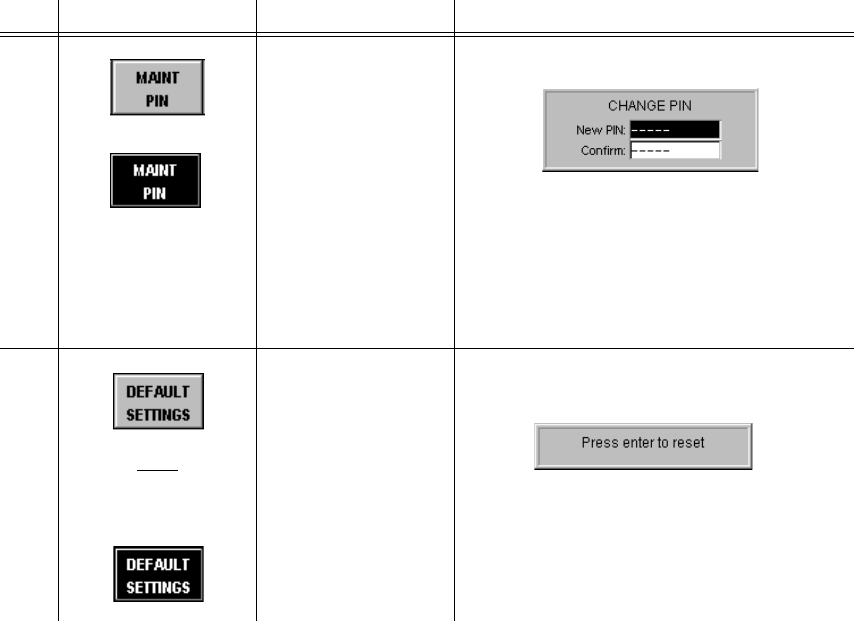
065 75$16&(,9(5 ; $ ; $
Operator’s Manual • Use under Special Conditions
– 3.30 – 6076.0822.12.01
No. Control Action Notes
9 Press softkey
MAINT PIN.
Abort entry.
Entry of new maintenance PIN
1. Enter the new PIN number by using the nu-
merical keypad, then press ENTER.
2. Confirm the new PIN number by repeating
the entry by using the numerical keypad,
then press ENTER.
See also chapter 3.6.
10
1RWH
,Q5DGLRVHVVLRQWKLV
VRIWNH\LVHQDEOHG
Press softkey
DEFAULT
SETTINGS.
Abort process.
Resets all maintenance parameters of
transceiver to default settings.
See List of Default Parameters in Appen-
dix A1.

065 75$16&(,9(5 ; $ ; $
Operator’s Manual • Use under Special Conditions
6076.0822.12.01 – 3.31 –
0HQX3DJH5$',20$,17(1$1&(
Starting point: Menu 400, page 1
+Press softkey (1) and the following display appears:
+Press the relevant softkey to call one of these menus.
softkey PAGE 1/2 MORE...
for
future
use
for
future
use
0HQX
0HQX
0HQX
0HQX
page 1
0HQX
0HQX
0HQX
0HQX
0HQX0HQX

065 75$16&(,9(5 ; $ ; $
Operator’s Manual • Use under Special Conditions
– 3.32 – 6076.0822.12.01
0HQX5$',2,19(1725<
This menu gives a survey of all hardware, software and firmware components installed in
M3SR Transceiver X. 4410A or X. 4460A.
Starting point: Menu 400, page 1 (RADIO MAINTENANCE)
+Press softkey (4) and the following display appears:
No. Control Action Notes
2 Press softkey
EQUIP.
Select setting.
Selection of equipment for radio inven-
tory
Depending on the item selected the fol-
lowing components are listed:
$// all components installed
&/components of CL1
): firmware components
+: all hardware components
6: all software components
+:02'name of the HW module article
6:02'name of the SW module article
'(9XT 4410A or X. 4460A
softkey INVENTORY...
see Appendix A1 Slot No. (see Menu 510)
T
ypes:
D
EV - device, e.g. XT 4410A
S
WM - identifier for software package
S
W - identifier for software
F
W - identifier for firmware
H
WM - identifier for hardware module
H
W - identifier for hardware
0HQX
Hardware installation
slot
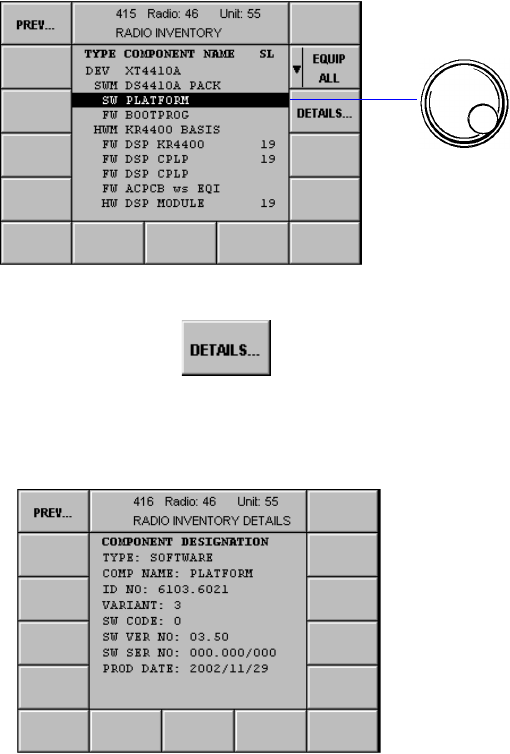
065 75$16&(,9(5 ; $ ; $
Operator’s Manual • Use under Special Conditions
6076.0822.12.01 – 3.33 –
0HQX5$',2,19(1725<'(7$,/6
This menu displays administrative data of a component.
Starting point: Menu 415 (RADIO INVENTORY)
+Press softkey (3) and the following display appears:
+Select component.
softkey DETAILS...
Example: Software Designation The data for the component selected in
Menu 415 comprise the following:
Type (hardware, software,
firmware)
Name of module or software
Ident. No.
Variant
Code No.
Version No.
Serial No.
Production Date
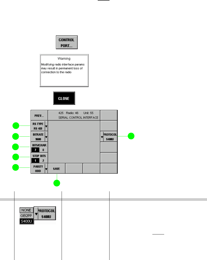
065 75$16&(,9(5 ; $ ; $
Operator’s Manual • Use under Special Conditions
– 3.34 – 6076.0822.12.01
0HQX5$',2&21752/3257
Via this menu the serial control port parameters can be viewed and edited.
1RWH
2QHRIWKHSDUDPHWHUVWREHFRQILJXUHGLQ0HQXLVWKHSURWRFROIRUGDWDFRPPXQLFDWLRQYLD
VHULDOFRQWUROSRUW;,UUHVSHFWLYHRIWKLVVHWWLQJWKHSURWRFROXVHGDWWKH/$1LQWHUIDFHV
;DQG;LVDOZD\V*%33
Starting point: Menu 400, page 1 (RADIO MAINTENANCE)
+Press softkey (14) and the following message appears:
+Press softkey (9) and the following display appears:
No. Control Action Notes
3 Press softkey
PROTOCOL.
Select setting.
Selection of protocol type
121(no remote control via control port
*%33 remote control via GB2PP protocol is
possible (RS 232, RS 422)
1RWH
2QO\IRUSRLQWWRSRLQWFRQQHFWLRQ
68 remote control via S400U protocol is
possible (RS 232, RS 422, RS 485)
3D\DWWHQWLRQWRWKH:DUQLQJ
softkey CONTROL PORT...

065 75$16&(,9(5 ; $ ; $
Operator’s Manual • Use under Special Conditions
6076.0822.12.01 – 3.35 –
9 Press softkey
SAVE. Saves the current settings.
The asterisk (*) indicates that the new set-
tings have not yet been stored.
10 Press softkey
PARITY.
Select setting.
Selection of parity
121(no parity
(9(1even number of bits
2'' odd number of bits
63$&(parity fixed at 0
0$5. parity fixed at 1
11 Press softkey
STOP BITS. Setting the number of stop bits
12 Press softkey
BITS/CHAR. Setting the number of bits in the telegram
13 Press softkey
BITRATE.
Select setting.
Selection of bitrate
14 Press softkey
RS TYPE.
Select setting.
Selection of serial port standard.
1RWH
5HJDUGLQJWKH56LQWHUIDFHSOHDVH
WDNHQRWHRIWKHIROORZLQJ
&60$&'&DUULHU6HQVH0XOWLSOH$FFHVV
ZLWK&ROOLVLRQ'HWHFWLRQLVQRWVXSSRUWHG
E\WKHUDGLR%XVRSHUDWLRQLVRQO\SRVVL
EOHZLWK68SURWRFROVHHVRIWNH\
DQG&RQWURO8QLW*%DSSOLFDWLRQSUR
WRFROSUHYHQWVFROOLVLRQV
No. Control Action Notes
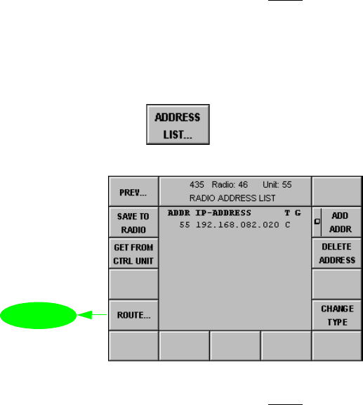
065 75$16&(,9(5 ; $ ; $
Operator’s Manual • Use under Special Conditions
– 3.36 – 6076.0822.12.01
0HQX5$',2$''5(66/,67
1RWH
:LWK065 7UDQVFHLYHU;7 $WKHDGGUHVVRIWKHLQWHJUDWHGFRQWUROXQLW
QHHGVWREHHQWHUHGKHUH
Starting point: Menu 400, page 1 (RADIO MAINTENANCE)
+Press softkey (13) and the following display appears:
1RWH
:HUHFRPPHQGWRHQWHUDOVRWKHUDGLR¶VRZQDGGUHVVORJLFDODQG,3DGGUHVV,I\RXIDLOWRGR
VRDQGWKHQSUHVVVRIWNH\*(7)5205$',2VHHFKDSWHUODWHURQQRFRQQHFWLRQZLOO
EHHVWDEOLVKHGIURPWKHFRQWUROXQLWWRWKHUDGLR
softkey ADDRESS LIST...
0HQX

065 75$16&(,9(5 ; $ ; $
Operator’s Manual • Use under Special Conditions
6076.0822.12.01 – 3.37 –
0HQX5$',2$''5(665287(
For addressing the M3SR devices the Internet Protocol (IP) is used. Therefore a unique IP
address needs to be assigned to each device, permitting the device to be identified and
addressed without ambiguity. In addition, each device needs a freely selectable logical address
in the range from 000 to 999, which is the address to be entered in Menu 010 (RADIO
CONNECTION) for addressed operation. The logical address spares the operator the tedious
task of entering the complex IP addresses.
Via Menu 436 the own address (logical and IP address) can be entered. When specifying the
Subnet Mask and the IP addresses (own and Gateway), please observe the IETF (= Internet
Engineering Task Force) standards (RFC pages (= Request for Commands)), in particular:
q796: Address Mappings
q940: Toward an Internet Standard Scheme for Subnetting
q950: Internet Standard Subnetting Procedure
q1219: On the Assignment of Subnet Numbers
q1517: Applicability Statement for the Implementation of Classless Inter-Domain
Routing
q1519: Classless Inter-Domain Routing: an Address Assignment and Aggregation
Strategy
q1918: Address Allocation for Private Internets
In compliance with RFC1918 the following address ranges are reserved for private networks:
q10.0.0.0 to 10.255.255.255, associated subnet mask 255.0.0.0
q172.16.0.0 to 172.31.255.255, associated subnet mask 255.255.0.0
q192.168.0.0 to 192.168.0.255, associated subnet mask 255.255.255.0
The subnet mask defines the respective address parts for network address and local address.
1RWH
•,3DGGUHVVHVDQGDUHQRWSHUPLWWHGWREHXVHG
•)RUWKHQHWLQIUDVWUXFWXUHHJURXWHUZHUHFRPPHQGWRXVHWKHORZHUORFDODGGUHVVHV
Network address Local address
Subnet mask 255 255 255 0
IP addresses 192 168 0 0
::::
192 168 0 255
max. 256 units
0 reserved for network
255 reserved for broadcas
t

065 75$16&(,9(5 ; $ ; $
Operator’s Manual • Use under Special Conditions
– 3.38 – 6076.0822.12.01
Starting point: Menu 435 (RADIO ADDRESS LIST)
+Press softkey (11) and the following display appears:
No. Control Action Notes
2 Press softkey LOG
ADDR.
Change value.
Changing the own logical address:
Range of values: 001 to 999
3 Press softkey
IP ADDR.
Change value.
Changing the own IP address:
11 Press softkey
GATEWAY ADDR.
Change value.
Changing the gateway address:
12 Press softkey
SUBNET MASK.
Change value.
Changing the subnet mask:
softkey ROUTE...
1RWH
ZLOOGHOHWHDQH[LVWLQJ
JDWHZD\DGGUHVV

065 75$16&(,9(5 ; $ ; $
Operator’s Manual • Use under Special Conditions
6076.0822.12.01 – 3.39 –
14 Press softkey
SAVE TO RADIO. Saves address and subnet mask to the
radio.
The asterisk (*) indicates that the new set-
tings have not yet been stored.
qWhen softkey SAVE * has been
pressed, the radio automatically per-
forms a restart.
qThe following display appears:
+Switch radio off and on again.
+Enter the radio address (see Menu
010).
No. Control Action Notes
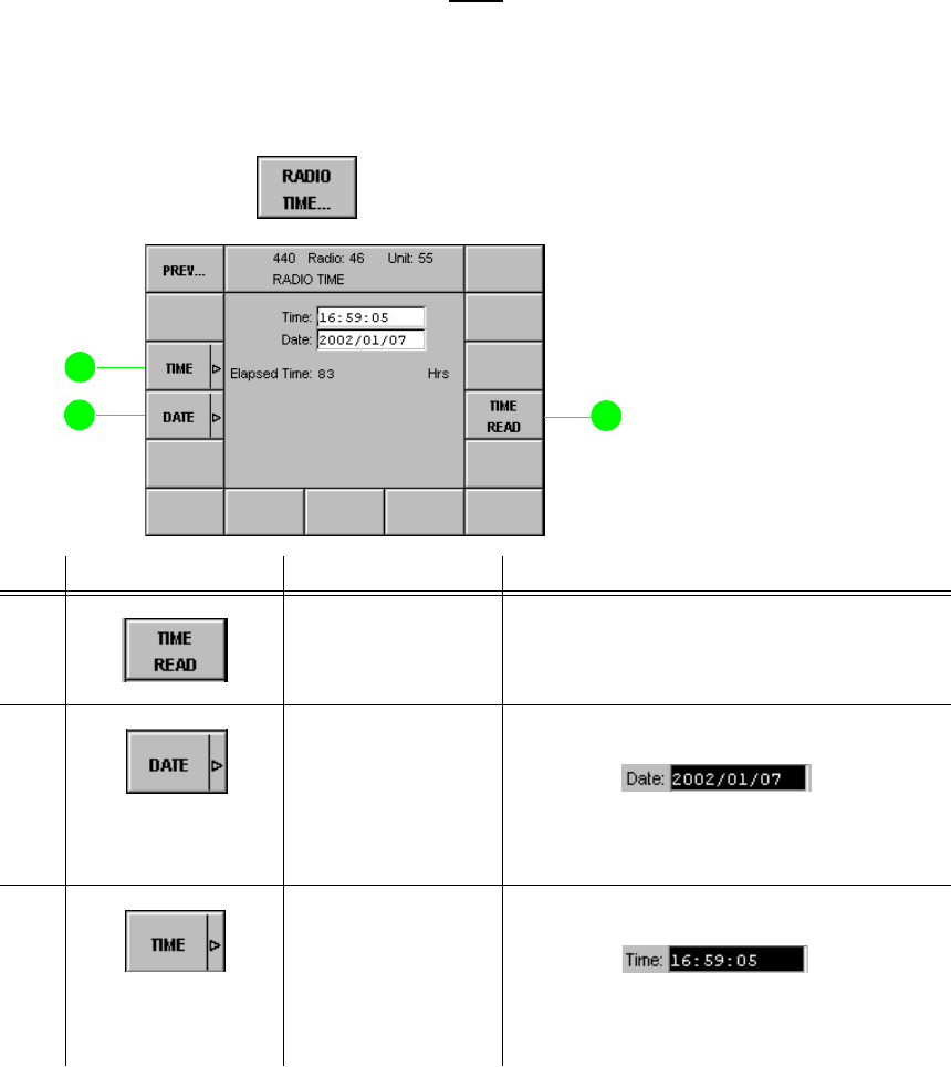
065 75$16&(,9(5 ; $ ; $
Operator’s Manual • Use under Special Conditions
– 3.40 – 6076.0822.12.01
0HQX5$',27,0(DQG'$7(
Via this menu the time and date stored in the radio can be edited.
1RWH
7KHWLPHDQGGDWHHQWHUHGKHUHDUHRQO\XVHGWRGHWHUPLQHZKHQH[DFWO\DQHUURURFFXUUHG
7LPHGDWHDQGHUURUDUHUHFRUGHGLQWKHHUURUOLVW0HQX5$',2(5525/,67
RU0HQX&8(5525/,67
Starting point: Menu 400, page 1 (RADIO MAINTENANCE)
+Press softkey (11) and the following display appears:
No. Control Action Notes
4 Press softkey
TIME READ. When softkey TIME READ is pressed,
GB 4000C starts reading the current time
and date from the connected radio.
12 Press softkey
DATE.
Set value.
Setting a new date
The year can be set between 1999 and
2037. The date within the radio is ad-
justed accordingly.
13 Press softkey
TIME.
Set value.
Setting a new time
The time is entered in 24 h format. The
time within the radio is adjusted accord-
ingly.
softkey RADIO TIME...
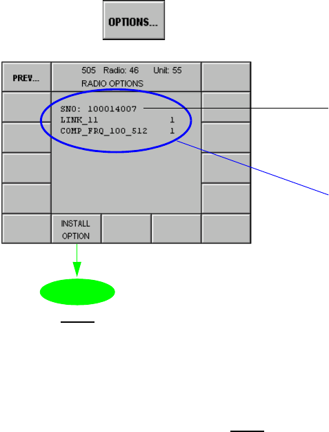
065 75$16&(,9(5 ; $ ; $
Operator’s Manual • Use under Special Conditions
6076.0822.12.01 – 3.41 –
0HQX5$',2237,216
In this menu all available radio options are listed.
Starting point: Menu 400, page 2 (RADIO MAINTENANCE)
+Press softkey (2) and the following display appears:
1RWH
7KH6126HULDO1XPEHURIWKHRSWLRQVFRQWUROOHULVWKHQXPEHU\RXQHHGWRVSHFLI\ZKHQRU
GHULQJDQHZRSWLRQIURP5RKGH6FKZDU]<RXZLOOWKHQJHWD62&6RIWZDUH2SWLRQV&RQ
WUROOHUILOHWKDWFDQEHORDGHGE\XVLQJWKH6HUYLFH0DLQWHQDQFH7RRO
softkey OPTIONS...
1RWH
,Q5DGLRVHVVLRQVRIWNH\,167$//
237,21LVHQDEOHG
List of radio options which
are installed and can there-
fore be activated
0HQX
Serial no. of options
controller
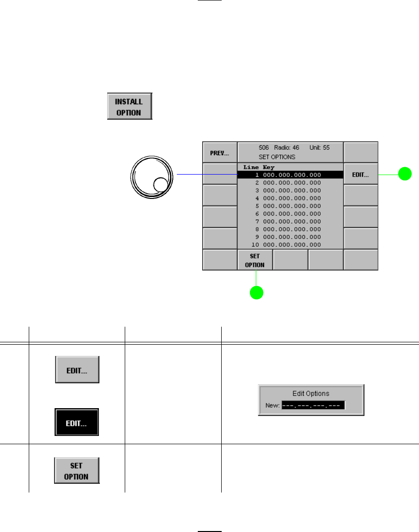
065 75$16&(,9(5 ; $ ; $
Operator’s Manual • Use under Special Conditions
– 3.42 – 6076.0822.12.01
0HQX6(7237,216
1RWH
2SWLRQFRGHVFDQEHVWEHORDGHGLQWRWKHUDGLRYLD/$1E\XVLQJWKH566HUYLFH0DLQWH
QDQFH7RRO=6,GHQWQR
In this menu any new option can be installed. The data which need to be entered must be re-
quested from the manufacturer.
Starting point: Menu 505 (RADIO OPTIONS)
+Press softkey (9) and the following display appears:
1RWH
$IWHUORDGLQJDQRSWLRQFRGHHLWKHUYLDWKH/$1LQWHUIDFHDQGWKH6HUYLFH0DLQWHQDQFH7RRO
=6RUE\LQSXWLQ0HQXYLDWKHQXPHULFDONH\SDGVZLWFKWKHUDGLRRIIDQGRQDJDLQ
$OORZDSSUR[LPDWHO\PLQXWHIRUWKHRSWLRQWREHDFWLYDWHG
No. Control Action Notes
2 Press softkey
EDIT...
Abort entry.
In order to enable further options the new
keys are to be entered.
9 Press softkey SET
OPTIONS. Activates options which are already in-
stalled.
softkey INSTALL OPTION
+Select line where
key is to be en-
tered.

065 75$16&(,9(5 ; $ ; $
Operator’s Manual • Use under Special Conditions
6076.0822.12.01 – 3.43 –
0HQX5$',202'8/(6
In this menu the individual radio modules are assigned to the Comlines.
Starting point: Menu 400, page 2 (RADIO MAINTENANCE)
+Press softkey (3) and the following display appears:
No. Control Action Notes
2 Press softkey
PARAMS... Switches to one of the following menus
depending on the module selected.
In the following menus module parameters
can be edited:
Platform: 0HQX
AFI (AF interface): 0HQX
Platform interfaces: IRUIXWXUHXVH
Receiver: 0HQX
Transmitter: 0HQX
Synthesizer: 0HQX
softkey RADIO... MODULES
1RWH
,Q5DGLRVHVVLRQVRIWNH\&/
LVHQDEOHG
6RIWNH\3$5$06SURYLGHV
DFFHVVWRIXUWKHUPHQXV
ZKHUHPRGXOHSDUDPHWHUV
FDQEHHGLWHGIRU'HIDXOW
6HWWLQJVVHH$SSHQGL[$
COM line
1 = Comline number
A = all, module is a common resource
(assigned to all Comlines)
Module slot
+Select module.
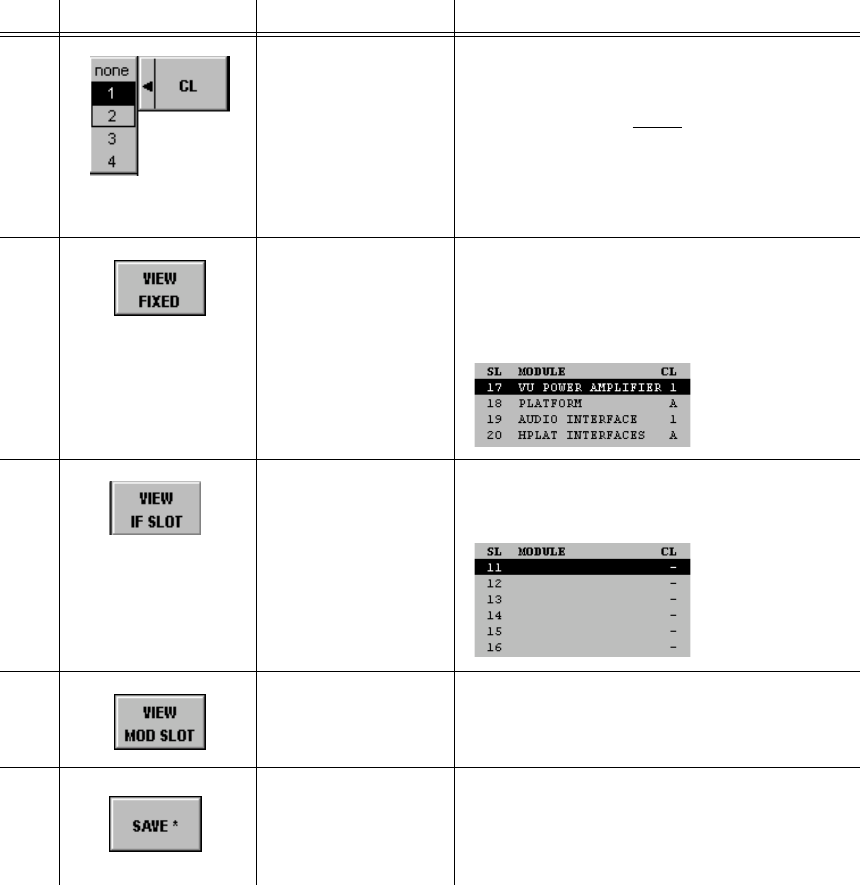
065 75$16&(,9(5 ; $ ; $
Operator’s Manual • Use under Special Conditions
– 3.44 – 6076.0822.12.01
3 Press softkey CL.
Select value.
The selected module is assigned to one
of the radio Comlines.
1RWH
:LWK0657UDQVFHLYHU; $RU
; $RQH&RPOLQHLVDYDLODEOH&RP
OLQHVWRDUHLQDFWLYH,Q5DGLRVHVVLRQ
VRIWNH\&/LVHQDEOHG
7 Press softkey
VIEW FIXED. Displays a list of "fixed" modules, that is,
modules that are firmly built in (for in-
stance slot no. 18 for platform, 19 for au-
dio interface).
8 Press softkey
VIEW IF SLOT. Displays a list of interface modules at the
rear (11 to 16, backplane, IF slots).
9 Press softkey
VIEW MOD SLOT. Displays a list of plug-in modules (0 to
10). For display see previous page.
14 Press softkey
SAVE. Saves the current configuration.
The asterisk (*) indicates that the new set-
tings have not yet been stored.
No. Control Action Notes
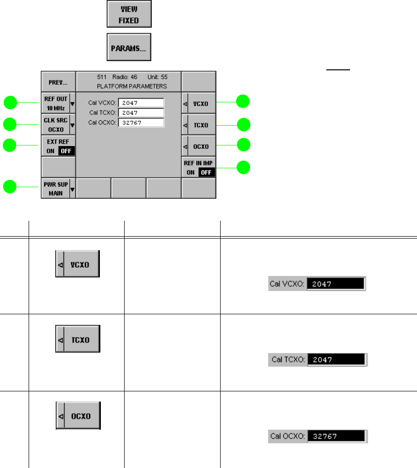
065 75$16&(,9(5 ; $ ; $
Operator’s Manual • Use under Special Conditions
6076.0822.12.01 – 3.45 –
0HQX3/$7)2503$5$0(7(56
In this menu radio platform parameters can be edited. The parameter default settings are fac-
tory-defined and should only be changed by service staff, for instance by using the R&S Serv-
ice & Maintenance Tool ZS 4400 (Ident. no. 6105.2600.02).
Starting point: Menu 510 (RADIO MODULES)
+Press softkey (7) and select module PLATFORM by using the tuning knob.
+Press softkey (3) and the following display appears:
No. Control Action Notes
2 Press softkey
VCXO.
Set value.
Setting the tuning value for the VCXO fre-
quency
Range of values: 0 to 4 095
3 Press softkey
TCXO.
Set value.
Setting the tuning value for the TCXO fre-
quency
Range of values: 0 to 4 095
4 Press softkey
OCXO.
Set value.
Setting the tuning value for the OCXO fre-
quency
Range of values: 0 to 65 535
1RWH
)RU'HIDXOW6HWWLQJVVHH$SSHQGL[
$
7KH9&;27&;2DQG2&;2
OHDYHWKHIDFWRU\FRUUHFWO\
FDOLEUDWHG$IWHUH[WHQGHGSHULRGV
RIRSHUDWLRQKRZHYHULWPD\EH
QHFHVVDU\WRUHFDOLEUDWHWKH
7&;2DQG2&;2WRFRPSHQVDWH
HIIHFWVRIDJLQJ7KLVVKRXOGEH
GRQHE\VHUYLFHVWDIIRQO\7KHGH
IDXOWVHWWLQJVHH$SSHQGL[$LV
QRWUHVWRUHGZKHQWKH'()$8/7
6(77,1*VRIWNH\LVSUHVVHG
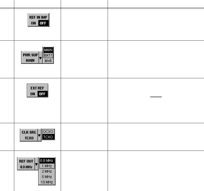
065 75$16&(,9(5 ; $ ; $
Operator’s Manual • Use under Special Conditions
– 3.46 – 6076.0822.12.01
5 Press softkey
REF IN IMP. Switches the input impedance of interface
X10 (Reference Frequency):
2)) input is high impedance
2150-Ω input at X10 enabled
10 Press softkey
PWR SUP.
Select setting.
Selection of the input to be monitored
(CBIT):
0$,1selects X31
%$77selects X32
0% selects both DC power inputs
12 Press softkey
EXT REF. Switches monitoring function on or off.
1RWH
,IWKHLQSXWLVPRQLWRUHG 21WKHLQWHU
QDO2&;2RU7&;2KDVWRV\QFKURQL]HWR
WKHH[WHUQDOUHIHUHQFHVLJQDO,IWKLVIDLOVD
&%,7PHVVDJHZLOOFRPHXS
13 Press softkey
CLK SRC.
Select setting.
Selection of the clock source
OCXO is recommended.
14 Press softkey
REF OUT.
Select setting.
Selection of the clock frequency for refer-
ence output X11
No. Control Action Notes
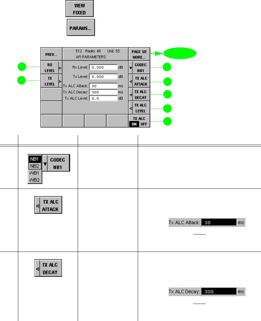
065 75$16&(,9(5 ; $ ; $
Operator’s Manual • Use under Special Conditions
6076.0822.12.01 – 3.47 –
0HQX3DJH$),3$5$0(7(56$XGLR)UHTXHQF\,QWHUIDFH
In this menu the parameters of the Audio Frequency Interface are displayed and edited (page
1 of 2). The default parameters have been selected to allow optimum performance. If, however,
changes were made at some point and the operator then wants to re-establish the default set-
tings (see Appendix A1), he only needs to press the Default softkey in Menu 400 (RADIO
MAINTENANCE).
Starting point: Menu 510 (RADIO MODULES)
+Press softkey (7) and select module AUDIO INTERFACE by using the tuning
knob.
+Press softkey (3) and the following display appears:
No. Control Action Notes
2 Press softkey
CODEC.
Select setting.
Selection of interface for level setting
The Rx level and Tx level are both as-
signed to the selected NB or WB channel.
3 Press softkey
TX ALC.
Enter value.
Entry of the TX ALC ATTACK time for
transmitter AF signals in the range from
10 ms to 100 ms, 30 ms is recommended.
1RWH
&XVWRPHUVSHFLILFVHWWLQJVFDQEHFRQILJXUHG
DVUHTXLUHG
4 Press softkey
ALC DECAY.
Enter value.
Entry of the ALC DECAY time for trans-
mitter AF signals in the range from
100 ms to 2 000 ms, 300 ms is recom-
mended.
1RWH
&XVWRPHUVSHFLILFVHWWLQJVFDQEHFRQILJXUHG
DVUHTXLUHG
page 2
0HQX
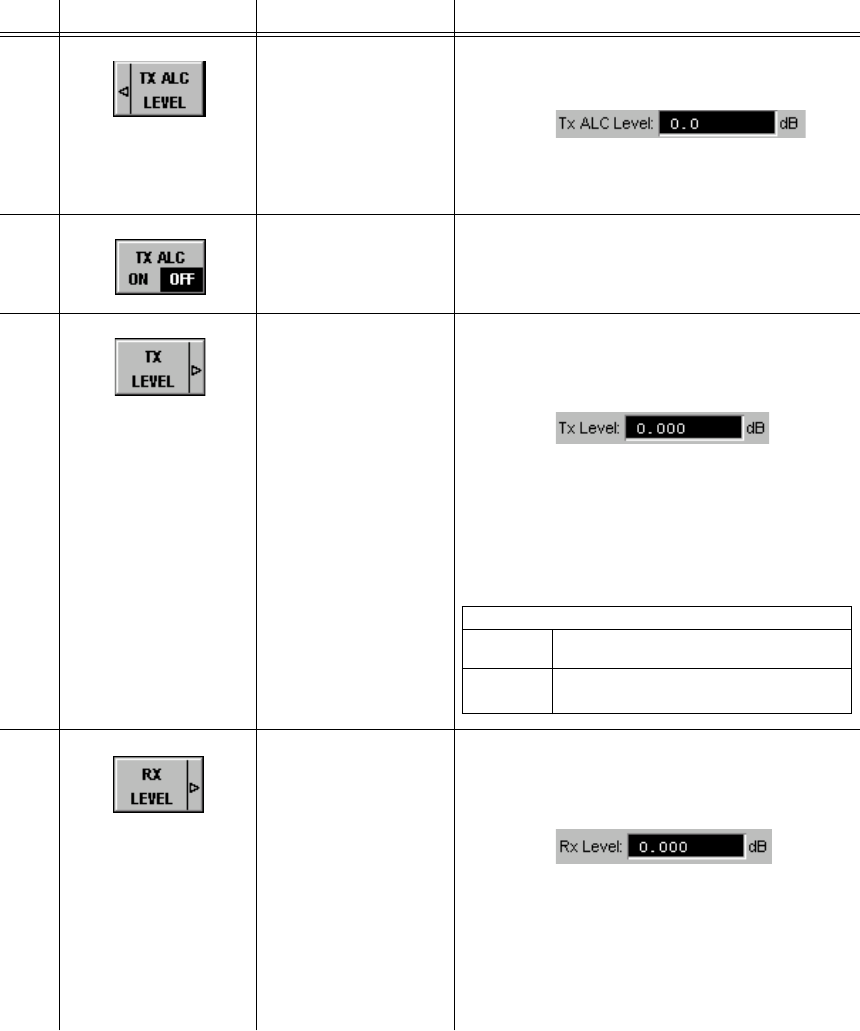
065 75$16&(,9(5 ; $ ; $
Operator’s Manual • Use under Special Conditions
– 3.48 – 6076.0822.12.01
5 Press softkey
TX ALC LEVEL.
Enter value.
Entry of the ALC level in the range from
-6.5 dB to + 6.5 dB
Output level of TX ALC
0 dB is recommended.
6 Press softkey TX
ALC. Switches the automatic level control
(ALC) for transmitter on or off.
13 Press softkey TX
LEVEL.
Enter value.
Entry of value for audio TX LEVEL into
600 Ω of interfaces NB1 and NB2 in the
range from -20 dB to +10 dB
For NB2 and device Link 11 (Menu 565
(DEVICE MAPPING)) the setting range is
between -3 and +3 dB.
For WB1 and WB2 the setting range is
between -3 and +15.5 dB relative to
1.4 Vpp.
14 Press softkey RX
LEVEL.
Enter value.
Entry of value for audio RX LEVEL into
600 Ω of interfaces NB1 and NB2 in the
range from -20 dB to +10 dB
For NB2 and device Link 11 (Menu 565
(DEVICE MAPPING)) the setting range is
between -3 and +3 dB.
For WB1 and WB2 the setting range is
between -3 and +15.5 dB relative to
1.4 Vpp.
No. Control Action Notes
Operation with ALC-TX
Setting Input range for constant modulation
depth or FM deviation
0 dBm -15 to +15 dBm
-15 dBm -30 to 0 dBm
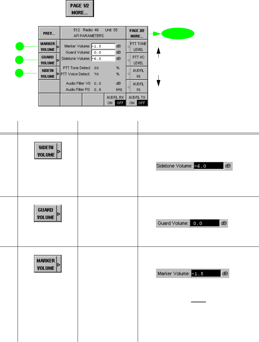
065 75$16&(,9(5 ; $ ; $
Operator’s Manual • Use under Special Conditions
6076.0822.12.01 – 3.49 –
0HQX3DJH$),3$5$0(7(56$XGLR)UHTXHQF\,QWHUIDFH
In this menu the parameters of the Audio Frequency Interface are displayed and edited (page
2 of 2). For Default Settings see Appendix A1.
Starting point: Menu 512, page 1
+Press softkey (1) and the following display appears:
No. Control Action Notes
12 Press softkey
SIDETN VOLUME.
Enter value.
Entry of value for SIDETONE VOLUME
in the range from -25.5 dB to 0 dB rela-
tive to selected audio Rx level
This is a narrowband voice sidetone
available at the audio NB-Rx output and
at the headset / loudspeaker.
13 Press softkey
GUARD VOLUME.
Enter value.
Entry of value for GUARD VOLUME in
the range from -25.5 dB to 0 dB
The Guard Volume is relative to the audio
Rx level.
14 Press softkey
MARKER
VOLUME.
Enter value.
Entry of value for MARKER VOLUME in
the range from -25.5 dB to 0 dB
The Marker Volume is relative to the au-
dio Rx level.
1RWH
7KLVVHWWLQJRQO\PDNHVVHQVHLI&LSKHU
8QLW.<LVPDSSHG7KHRSHUDWRULVLQ
IRUPHGYLDDFRXVWLFVLJQDOZKHQWKHWUDQV
FHLYHULVNH\HGLQSODLQWH[WPRGH
9'81&3
for
future
use
for future use
page 1
0HQX
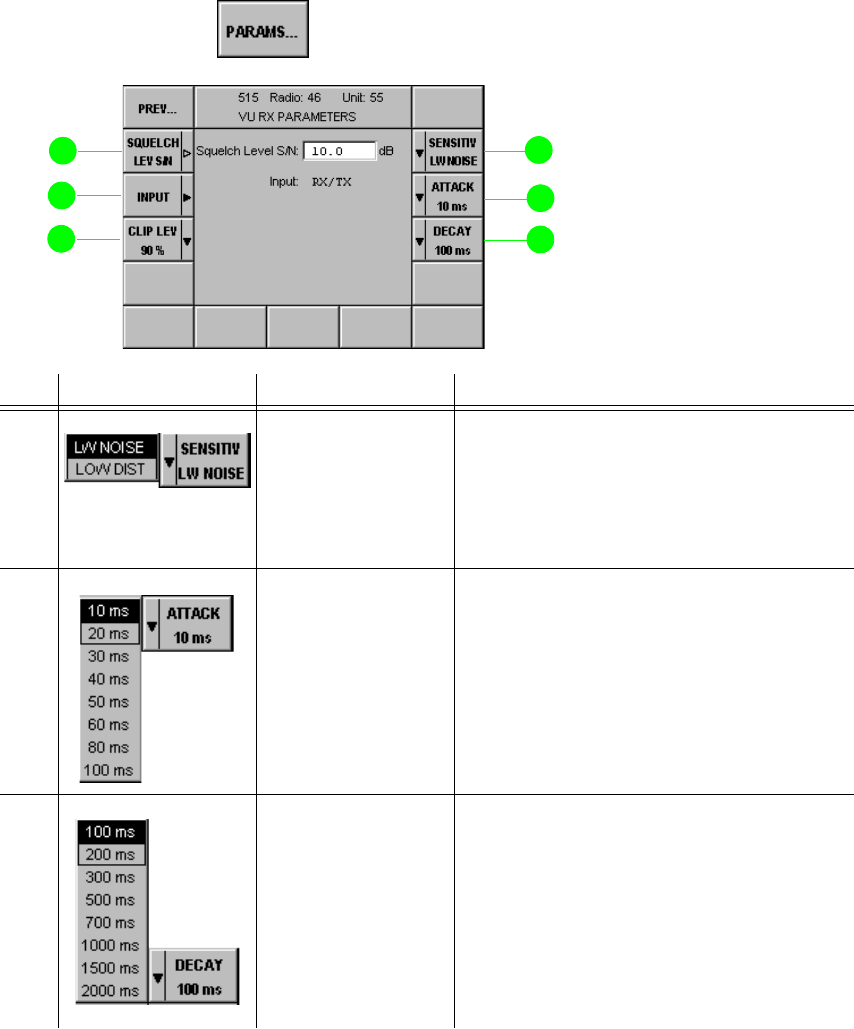
065 75$16&(,9(5 ; $ ; $
Operator’s Manual • Use under Special Conditions
– 3.50 – 6076.0822.12.01
0HQX985;3$5$0(7(56
In this menu receiver parameters are displayed and edited. For Default Settings see Appendix
A1.
Starting point: Menu 510 (RADIO MODULES)
+Select module VU RX (receiver) by using the tuning knob.
+Press softkey (3) and the following display appears:
No. Control Action Notes
2 Press softkey
SENSITIV LW
NOISE.
Select setting.
Selection of sensitivity
/2:12,6(
means high sensitivity of receiver
/2:',67257,21
means low sensitivity of receiver which is thus less
susceptible to interference
3 Press softkey
ATTACK.
Select value.
Selection of AF AGC attack time
The attack time is the time the receiver
needs for controlling the AF output signal
to 90% of its nominal output level when
the modulation depth has changed from
10% to 90%.
4 Press softkey
DECAY.
Select value.
Selection of AF AGC decay time
The decay time is the time the receiver
needs for controlling the AF output signal
to its nominal output level when the mod-
ulation depth has changed from 90% to
10%.
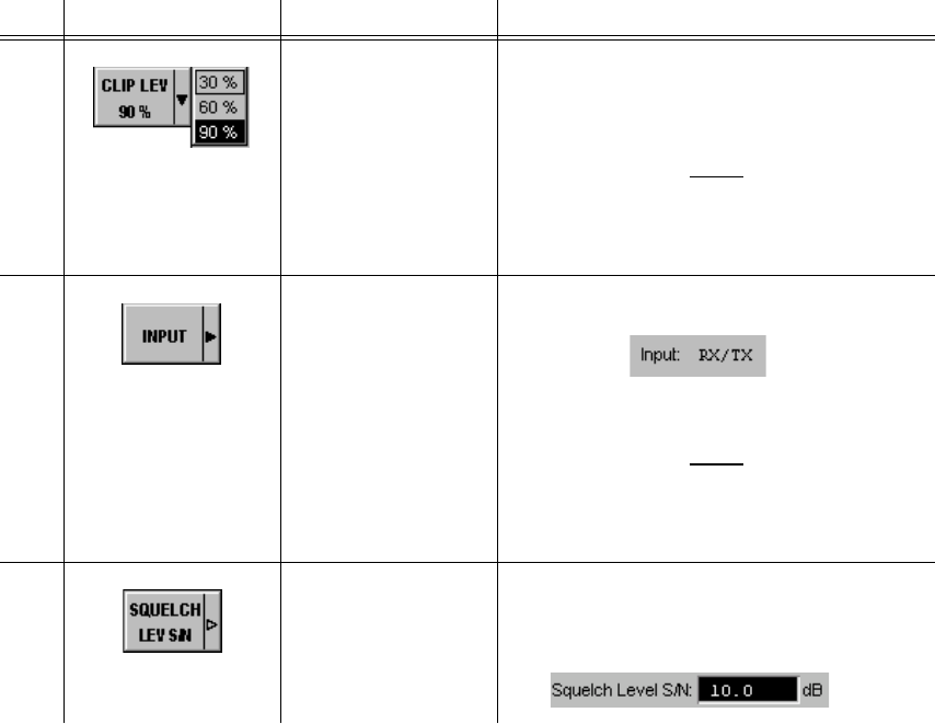
065 75$16&(,9(5 ; $ ; $
Operator’s Manual • Use under Special Conditions
6076.0822.12.02 – 3.51 –
12 Press softkey CLIP
LEV.
Select setting.
Selection of the clipper level
This is used for noise clipping after AM
voice demodulation.
1RWH
7KH&/,33(5LVVZLWFKHGRQDQGRIIE\
XVLQJVRIWNH\LQ0HQXSDJH
0$18$/),;)54
13 Press softkey
INPUT.
Select setting.
Selection of antenna input
When the common RX/TX antenna of a
transceiver is to be used select RX/TX.
1RWH
,QFRQMXQFWLRQZLWK$QWHQQD,QWHUIDFH
*, DQGZLWKRXW8+))LOWHU)'
VHOHFW5;LQDOORWKHUFDVHV5;7;LQSXW
14 Press softkey
SQUELCH
LEV S/N.
Set value.
Setting the response threshold of the S/N
squelch in the range from 6 to 20 dB
(only effective with Narrowband Voice)
No. Control Action Notes
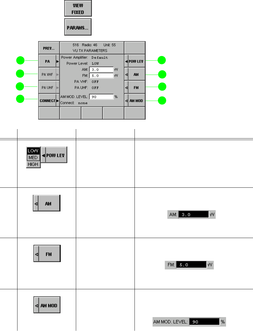
065 75$16&(,9(5 ; $ ; $
Operator’s Manual • Use under Special Conditions
– 3.52 – 6076.0822.12.01
0HQX987;3$5$0(7(56
In this menu the transmitter parameters are displayed and edited. For Default Settings and
Connection of Peripheral Equipment see Appendix A1.
Starting point: Menu 510 (RADIO MODULES)
+Press softkey (7) and select module VU POWER AMPLIFIER by using the
tuning knob.
+Press softkey (3) and the following display appears:
No. Control Action Notes
2 Press softkey
POW LEV.
Select setting.
Selection of edit fields for power levels
/2: editing the value for low power level
0(',80editing the value for medium power
level
+,*+ editing the value for high power
level
3 Press softkey
AM.
Set value.
Setting the AM transmit power (for LOW,
MEDIUM, HIGH)
For AM the power level (carrier unmodu-
lated) can be set to values from 1 to 30 W.
4 Press softkey
FM.
Set value.
Setting the FM transmit power (for LOW,
MEDIUM, HIGH)
For FM the power level can be set to val-
ues from 1 to 100 W.
5 Press softkey
AM MOD.
Set value.
Setting the AM modulation depth in the
range from 10 to 99%, 90% is recom-
mended.
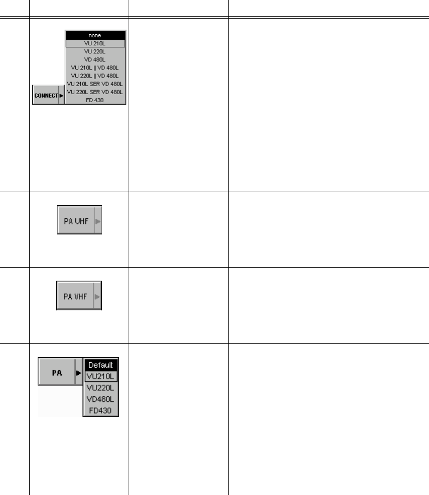
065 75$16&(,9(5 ; $ ; $
Operator’s Manual • Use under Special Conditions
6076.0822.12.01 – 3.53 –
11 Press softkey
CONNECT.
Select setting.
Defines whether an external power am-
plifier is connected at X. 4410A or
X. 4460A and selects its type:
98/ for future use
98/ for future use
9'/ UHF Amplifier
100 W AM
98/9'/ for future use
98/9'/ for future use
98/6(59'/ for future use
98/6(59'/ for future use
)'UHF Agile Filter
See Appendix A1, Connection of Periph-
eral Equipment.
12 Press softkey
PA UHF. Activates / deactivates operation with the
connected UHF amplifier.
The power amplifier can be activated via
software at one of the power levels LOW,
MED, and HIGH.
13 Press softkey
PA VHF. Activates / deactivates operation with the
connected VHF amplifier.
The power amplifier can be activated via
software at one of the power levels LOW,
MED, and HIGH.
14 Press softkey PA.
Select setting.
Selection of the configuration of the
power level for the external power ampli-
fier
'HIDXOW selects power level (LOW, MED,
HIGH) for use of X. 4410A or
X. 4460A without power amplfier
98/ for future use
98/ for future use
9'/ UHF Amplifier 100 W AM
)'UHF Agile Filter
See Appendix A1, Connection of Periph-
eral Equipment.
No. Control Action Notes

065 75$16&(,9(5 ; $ ; $
Operator’s Manual • Use under Special Conditions
– 3.54 – 6076.0822.12.01
0HQX986<13$5$0(7(56
In this menu the synthesizer parameters are displayed and edited. As the default settings have
been configured for optimum performance, changing them will not be necessary in most cases.
For Default Settings see Appendix A1.
Starting point: Menu 510 (RADIO MODULES)
+Select module VU SYN (synthesizer) by using the tuning knob.
+Press softkey (3) and the following display appears:
No. Control Action Notes
2 Press softkey
TX DEV FM NB.
Set value.
Setting the value for FM Deviation Nar-
rowband in the range from 1 kHz to
20 kHz, 3.5 kHz is recommended.
3 Press softkey
TX DEV FM WB.
Set value.
Setting the value for FM Deviation Wide-
band (analog) in the range from 1 kHz to
20 kHz, 6.25 kHz is recommended.
4 Press softkey
TX DEV FM LK11.
Set value.
Setting the value for TX Deviation for Link
11 operation in the range from 1 kHz to
20 kHz, 20 kHz is recommended.
5 Press softkey
TX DEV TRIM.
Set value.
Setting the value for fine tuning of syn-
thesizer FM modulator in the range from
-30% to 30%
This setting is effective for all analog pro-
cedures, not for Wideband Data Digital
FSK.
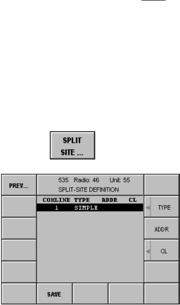
065 75$16&(,9(5 ; $ ; $
Operator’s Manual • Use under Special Conditions
6076.0822.12.01 – 3.55 –
0HQX63/,76,7('(),1,7,21
1RWH
1RWXVHGLQWKLVDSSOLFDWLRQ
Starting point: Menu 400, page 2 (RADIO MAINTENANCE)
+Press softkey (3) and the following display appears:
Softkey SPLIT SITE...
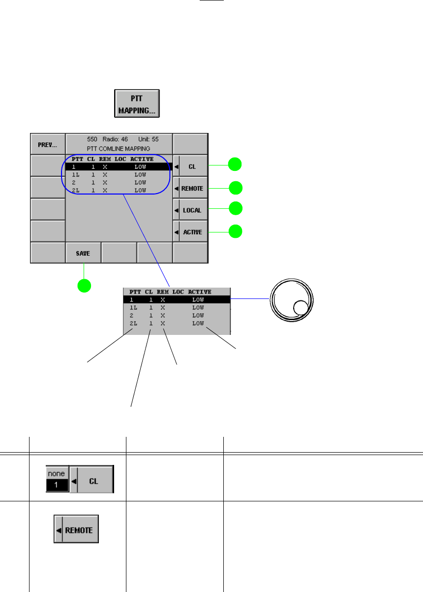
065 75$16&(,9(5 ; $ ; $
Operator’s Manual • Use under Special Conditions
– 3.56 – 6076.0822.12.01
0HQX377&20/,1(0$33,1*
1RWH
:HUHFRPPHQGQRWWRFRQILJXUHWKHNH\OLQHVIRUORFDOPRGHDVWKLVPD\UHVXOWLQXQZDQWHG
FDUULHUDFWLYDWLRQE\RQHRIWKHFRQQHFWHGGHYLFHV
In this menu the assignment of PTT lines to radio Comlines is displayed and edited. For Default
Settings See Appendix A1.
Starting point: Menu 400, page 2 (RADIO MAINTENANCE)
+Press softkey (14) and the following display appears:
No. Control Action Notes
2 Press softkey CL.
Select setting.
Selection of communication line for PTT
mapping
3 Press softkey
REMOTE. Selection of the active PTT line
An "X" then indicates that this line can be
selected by remote control only.
REMOTE means that the PTT line can be
operated only in remote control but not in
local control.
softkey PTT MAPPING...
PTT line interface (X25, X26) is only
active if radio is set to REMOTE
PTT contacts of X25
acc. to interface descrip-
tion in Appendix A1
Active Comline
Level of active keyline
+Select keyline.

065 75$16&(,9(5 ; $ ; $
Operator’s Manual • Use under Special Conditions
6076.0822.12.01 – 3.57 –
4 Press softkey
LOCAL. Selection of the active PTT line
An "X" then indicates that this line can be
selected by local control only.
The PTT line is only enabled if the radio is
set to LOCAL operation (key on Front
Panel).
5 Press softkey
ACTIVE. Selection of the PTT level of the current
line
9 Press softkey
SAVE. Saves the current configuration.
The asterisk (*) indicates that the new set-
tings have not yet been stored.
No. Control Action Notes
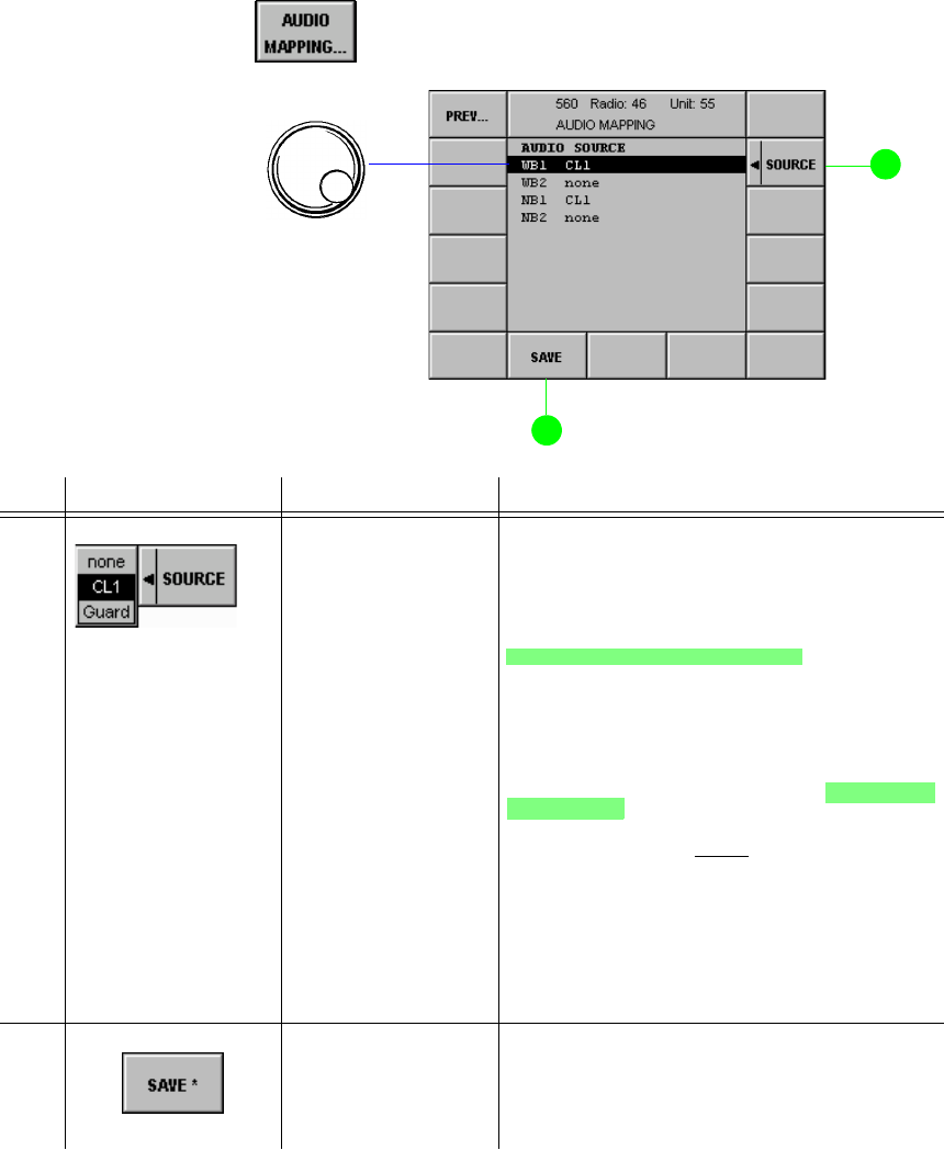
065 75$16&(,9(5 ; $ ; $
Operator’s Manual • Use under Special Conditions
– 3.58 – 6076.0822.12.02
0HQX$8',20$33,1*
In this menu the assignment of audio channels to Comlines is displayed and edited.
Starting point: Menu 400, page 2
+Press softkey (12) and the following display appears:
No. Control Action Notes
2 Press softkey
SOURCE.
Select setting.
Assigns the selected audio port to the
Comline.
&/
Audio port is dedicated to Comline CL1 modules. In
communication mode V/D UNCP any AF signal
from the guard receiver will be added to the nar-
rowband interface if the mixer is switched on via
softkey GUARD (Menus 110 / 210).
*8$5'
Audio port is exclusively for AF signals from the
guard receiver. Any AF signal from the guard re-
ceiver will be output at the NB2 port in all communi-
cation modes.
1RWH
:HUHFRPPHQGWRVZLWFKRQWKHPL[HUYLD
VRIWNH\*8$5'0HQXVIRU
ERWK$)VLJQDOV9+)DQG8+)
7KLVJXDUDQWHHVWKH$)VLJQDORXWSXWIURP
WKHJXDUGUHFHLYHULQDOOFRPPXQLFDWLRQ
PRGHV
9 Press softkey
SAVE. Saves the current configuration.
The asterisk (*) indicates that the new set-
tings have not yet been stored.
softkey AUDIO MAPPING...
+Select audio line
NB: Voice info
WB: Data info
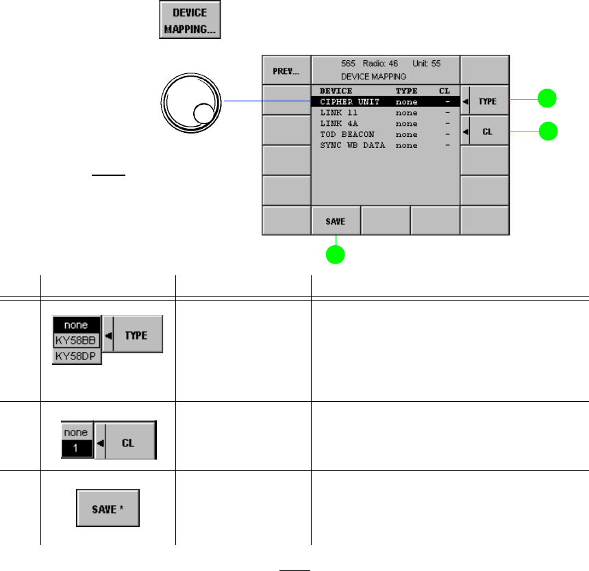
065 75$16&(,9(5 ; $ ; $
Operator’s Manual • Use under Special Conditions
6076.0822.12.01 – 3.59 –
0HQX'(9,&(0$33,1*
In this menu the assignment of radio configurations (e.g. Link 11) to Comlines is displayed and
edited.
Starting point: Menu 400, page 2 (RADIO MAINTENANCE)
+Press softkey (11) and the following display appears:
1RWH
•$VDUHVXOWRIGHYLFHPDSSLQJDOOWKHUHOHYDQWUDGLRVHWWLQJVVXFKDVUHVRXUFHDVVLJQPHQWLQWHUQDO
VLJQDOSURFHVVLQJHWFDUHPDGH
•:KHQWKHH[WHUQDOGHYLFHKDVEHHQFRQQHFWHGWRWKH&RPOLQHEHDEVROXWHO\VXUHWRVZLWFKWKH
UDGLRRIIDQGRQDJDLQ
•$IWHUVZLWFKRQFKHFNLIDXGLROLQH0HQX$8',20$33,1*DQGNH\OLQH0HQX377
&20/,1(0$33,1*KDYHEHHQPDSSHGFRUUHFWO\
•&$87,21:KHQUHPRYLQJWKHH[WHUQDOGHYLFHIURPWKH&RPOLQHDOOSUHYLRXVO\XVHGUHVRXUFHV
ZLOOEHFRPHIUHHDJDLQ7KHUHIRUHDOZD\VFKHFNERWKDXGLRPDSSLQJ0HQXDQG377PDS
SLQJ0HQX
No. Control Action Notes
2 Press softkey
TYPE.
Select setting.
Defines the type of a selected radio con-
figuration. At present, this function is
available with cipher units only.
.<%% = Baseband mode
.<'3 = Diphase mode
3 Press softkey CL.
Select setting.
Assigns the selected device to a Comline.
9 Press softkey
SAVE. Saves the current configuration.
The asterisk (*) indicates that the new set-
tings have not yet been stored.
softkey DEVICE MAPPING...
+Select device
1RWH
/,1.$DQG72'%($&21
DUHIRUIXWXUHXVH
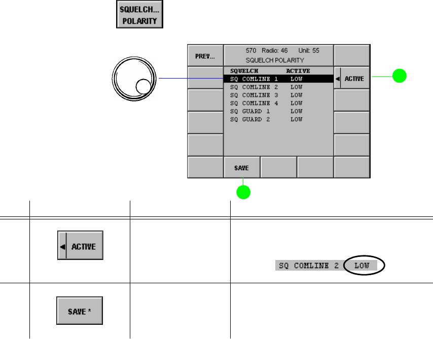
065 75$16&(,9(5 ; $ ; $
Operator’s Manual • Use under Special Conditions
– 3.60 – 6076.0822.12.01
0HQX648(/&+32/$5,7<
In this menu the polarity of the squelch signal output level is displayed and edited.
Starting point: Menu 400, page 2 (RADIO MAINTENANCE)
+Press softkey (10) and the following display appears:
No. Control Action Notes
2 Press softkey
ACTIVE. The active polarity is switched from low to
high and vice versa:
9 Press softkey
SAVE. Saves the current configuration.
The asterisk (*) indicates that the new
settings have not yet been stored.
softkey SQUELCH... POLARITY
Active level:
High - positive polarity
Low - level 0 V
+Select squelch

065 75$16&(,9(5 ; $ ; $
Operator’s Manual • Use under Special Conditions
6076.0822.12.02 – 3.61 –
0HQX)52173$1(/$8',26285&(
By using the SELECT key one of the AF sources for the loudspeaker can be selected that have
been configured in Menu 575, e.g. CL1 or Guard U/V.
When CL1 is selected as AF source and communication mode V/D UNCP is active, the guard
receiver AF signal can be output at the loudspeaker in addition to the main receiver AF signal,
depending on the GUARD configuration (see Menu 110 (MANUAL FIX.FRQ), page 1 and
Menu 210, page 1 (USER PRESET FIX.FRQ)).
The following table shows how LEDs 1 and 2 are related and which AF signal is output by the
loudspeaker.
Starting point: Menu 400, page 2 (RADIO MAINTENANCE)
+Press softkey (9) and the following display appears:
LED AF signal
12
no AF signal
OLJKWHGAF signal of main receiver and in addition of guard receiver, if
switched on via softkey GUARD in Menu 110 (MANUAL
FIX.FRQ) or 210 (USER PRESET FIX.FRQ).
IODVKLQJAF signal of guard receiver (VHF band)
IODVKLQJAF signal of guard receiver (UHF band)
IODVKLQJIODVKLQJAF signal of guard receiver (VHF and UHF bands)
LED 1 lighted
1. Press key LEDs 1 and 2 flashing
2. Press key none of the LEDs lighted
3. Press key LED 1 lighted
softkey AUDIO FRONTP...
+Select audio source
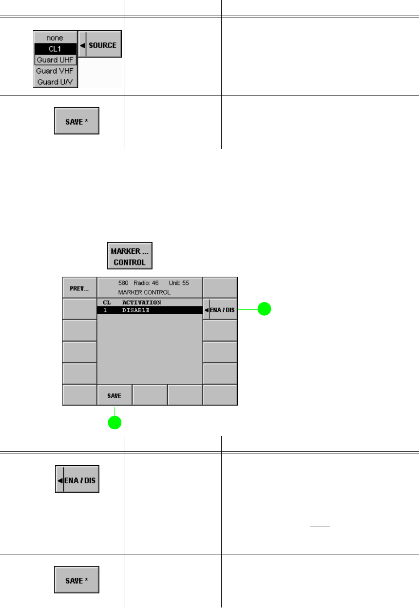
065 75$16&(,9(5 ; $ ; $
Operator’s Manual • Use under Special Conditions
– 3.62 – 6076.0822.12.02
0HQX0$5.(5&21752/
In this menu the marker for the selected Comline is enabled or disabled.
Starting point: Menu 400, page 2 (RADIO MAINTENANCE)
+Press softkey (7) and the following display appears:
No. Control Action Notes
2 Press softkey
SOURCE.
Select setting.
Assigns the Comline or guard receiver to
the audio output at the Front Panel (loud-
speaker, headset connector X7).
9 Press softkey
SAVE. Saves the current configuration.
The asterisk (*) indicates that the new set-
tings have not yet been stored.
No. Control Action Notes
2 Press softkey
ENA/DIS. Enables or disables the PLAIN marker
function. The marker tone itself is
switched on in Menu 110 (MANUAL
FIX.FRQ) or 210 (USER PRESET
FIX.FRQ).
1RWH
7KHPDUNHUWRQHLVWREHXVHGRQO\LI
&LSKHU8QLW.<LVPDSSHG
9 Press softkey
SAVE. Saves the current configuration.
The asterisk (*) indicates that the new set-
tings have not yet been stored.
softkey MARKER... CONTROL
065 75$16&(,9(5 ; $ ; $
Operator’s Manual • Use under Special Conditions
6076.0822.12.01 – 3.63 –
0HQX5$',26(783
Via the Radio Setup menus the PRESET PAGES (LOADED PAGES) are edited and stored.
One PRESET consisting of up to 200 Pages can be stored in the radio. Alternatively, the PRE-
SET may also be split up into two PRESETs with 100 Pages each.
Each PRESET PAGE is made up of a fixed frequency and an EPM section (not used in this
application). When a PRESET PAGE is called up in PRESET mode, one of these sections is
activated and the radio is set accordingly. Which section is to be activated in each case is de-
fined in the DEFAULT MODE setting, to be made in Menu 710.
Page storage within the radio is based on a redundancy concept. For more details on Loaded,
User and Current Pages see chapter 3.5.

065 75$16&(,9(5 ; $ ; $
Operator’s Manual • Use under Special Conditions
– 3.64 – 6076.0822.12.01
Starting point: Menu 040 (MAIN)
+Press softkey (5) and the following display appears:
+Enter setup PIN number (5 digits) by using the numerical keypad, then press ENTER.
qThe following display appears:
No. Control Action Notes
9 Press softkey
SETUP.
Abort entry.
Entry of a new setup PIN.
1. Enter the new PIN by using the numerical
keypad, then press ENTER.
2. Confirm the new PIN by repeating the entry
using the numerical keypad, then press EN-
TER.
See also chapter 3.6.
softkey SETUP...
for future use
0HQX
0HQX
0HQX
0HQX
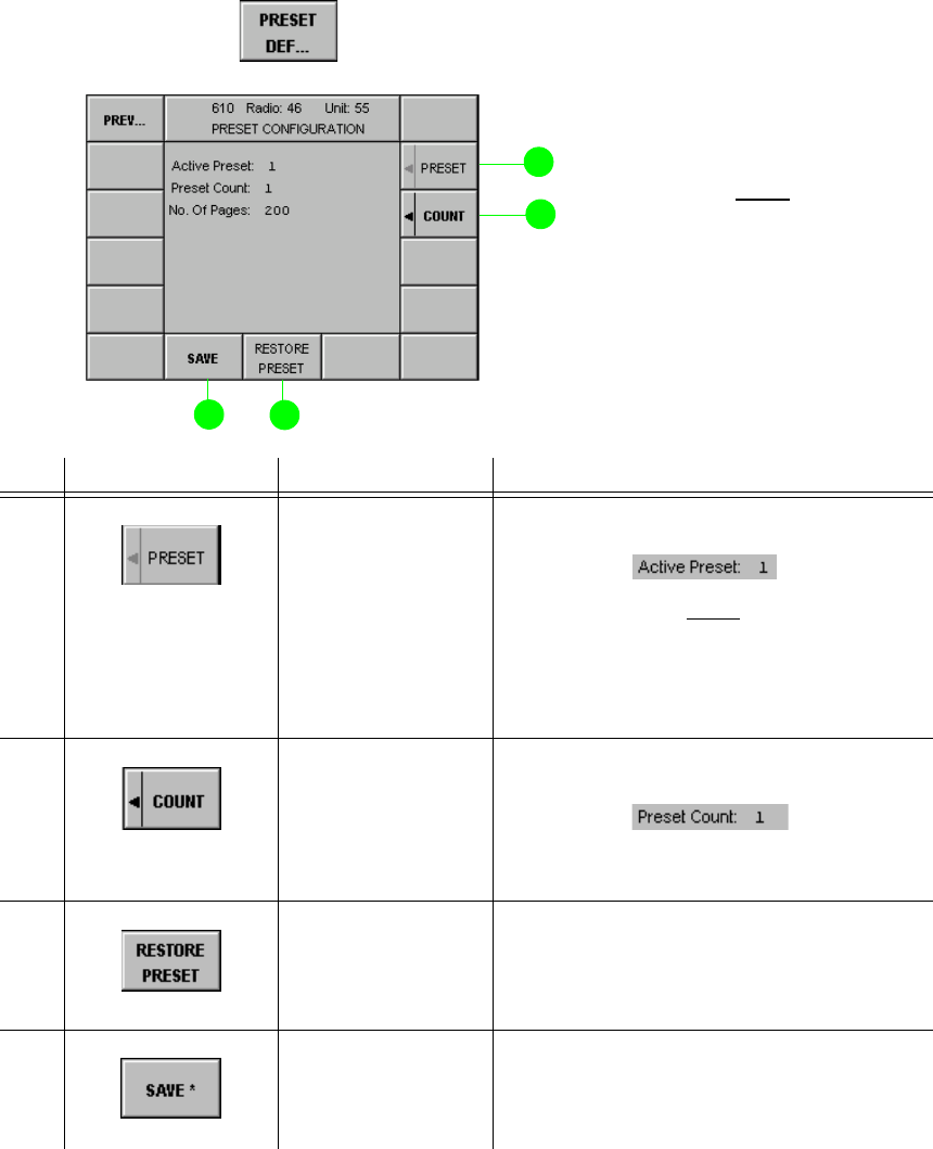
065 75$16&(,9(5 ; $ ; $
Operator’s Manual • Use under Special Conditions
6076.0822.12.01 – 3.65 –
0HQX35(6(7&21),*85$7,21
In this menu the Preset configuration is displayed and edited.
Starting point: Menu 600 (RADIO SETUP)
+Press softkey (2) and the following display appears:
No. Control Action Notes
2 Press softkey
PRESET. Switches between two active Presets.
1RWH
6ZLWFKLQJRYHUEHWZHHQ3UHVHWDQGLV
RQO\SRVVLEOHLI&RXQW
[SDJHVLVVHOHFWHG6RVRIWNH\
35(6(7LVHQDEOHGZLWKSUHVHWFRXQW
3 Press softkey
COUNT. Switches between two preset counts.
Count 2 is for 2 x 100 pages and
Count 1 is for 200 pages.
8 Press softkey
RESTORE
PRESET.
Restores the Preset configuration stored
in the radio. The Preset data are copied
from the Loaded Presets into the User
Presets.
9 Press softkey
SAVE. Saves the current configuration.
The asterisk (*) indicates that the new set-
tings have not yet been stored.
softkey PRESET DEF...
A Preset may consist of 200
or 2 x 100 Preset Pages.
1RWH
,Q5DGLRVHVVLRQVRIWNH\V35(
6(7&2817DQG6$9(DUH
HQDEOHG,Q&RPOLQHVHVVLRQ
VRIWNH\5(6725(35(6(7LV
HQDEOHG
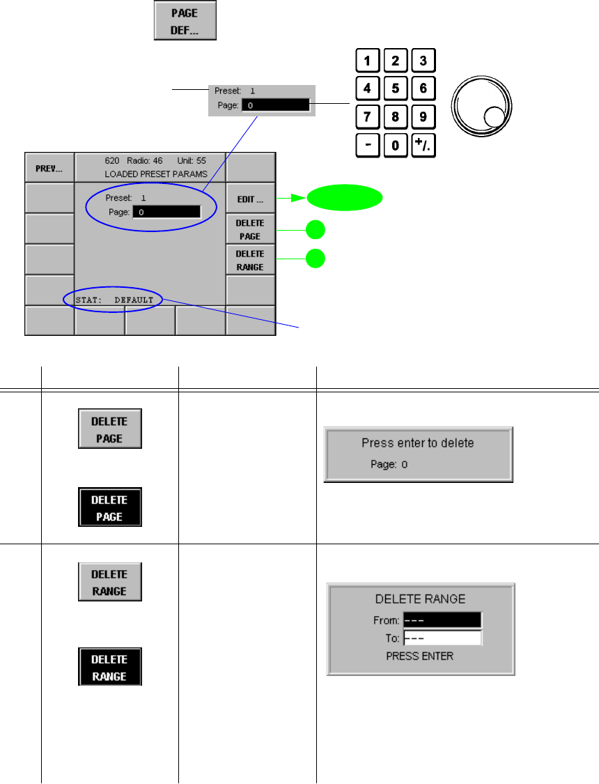
065 75$16&(,9(5 ; $ ; $
Operator’s Manual • Use under Special Conditions
– 3.66 – 6076.0822.12.01
0HQX/2$'('3$*(3$5$0(7(56
In this menu the individual LOADED PAGES can be selected and deleted.
Starting point: Menu 600 (RADIO SETUP)
+Press softkey (3) and the following display appears:
No. Control Action Notes
3 Press softkey
DELETE PAGE.
Abort entry.
Deletes specified page.
User-defined settings in the selected Pre-
set Page are replaced by default values
(see Default Settings in Appendix A1).
4 Press softkey
DELETE RANGE.
Abort entry.
Deletes from page xxx to page yyy.
The user-defined settings in the pages of
the specified range are deleted.
1. Enter start number by using the numerical
keypad, then press ENTER.
2. Enter stop number by using the numerical
keypad, then press ENTER.
softkey PAGE DEF...
0HQX
+Enter page no.
Active preset
DEFAULT: no customer-specific data loaded
LOADED: customer-specific data loaded
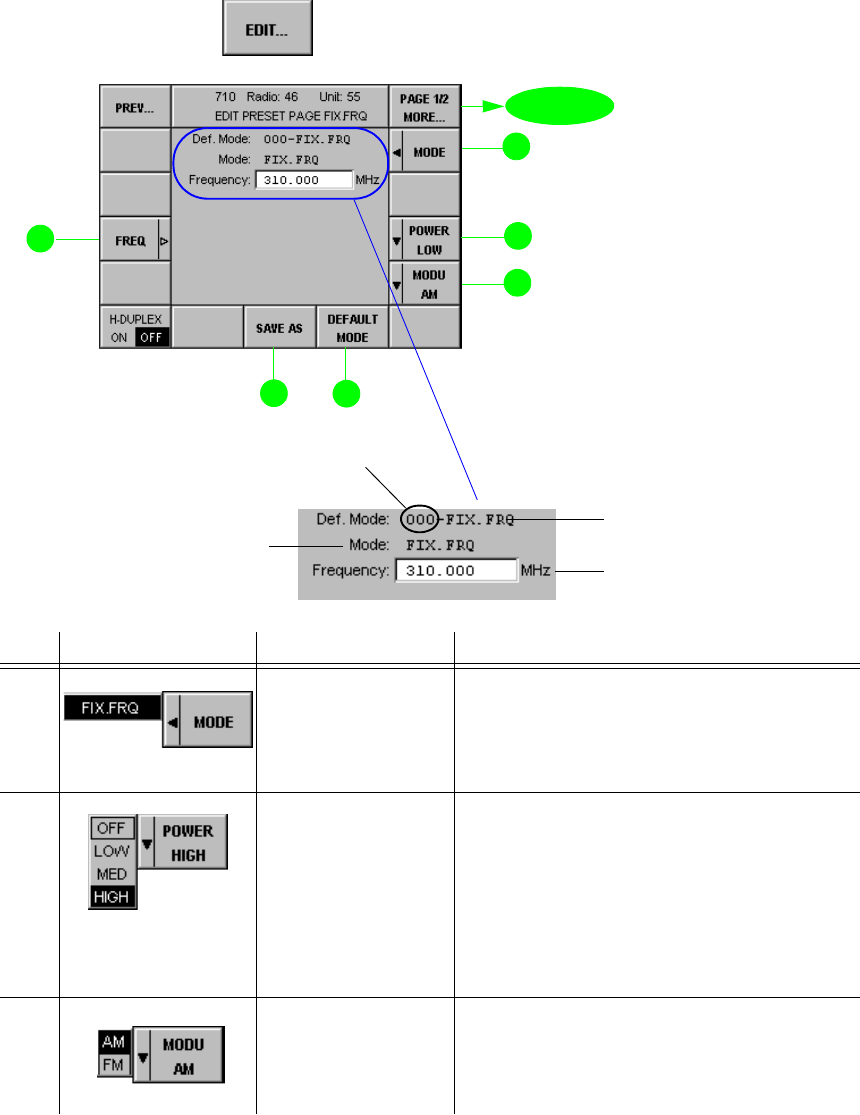
065 75$16&(,9(5 ; $ ; $
Operator’s Manual • Use under Special Conditions
6076.0822.12.01 – 3.67 –
0HQX3DJH(',735(6(73$*(),;)54)L[HG)UHTXHQF\
In this menu the settings of a Preset Page selected in Menu 620 (LOADED PRESET PARAMS)
are displayed, edited and stored (page 1 of 2).
Starting point: Menu 620 (LOADED PRESET PARAMS)
+Press softkey (2) and the following display appears:
No. Control Action Notes
2 Press softkey
MODE. Selection of the section of the Preset
Page to be edited or viewed
),;)54
only FIX. FRQ is possible
4 Press softkey
POWER.
Select setting.
Selection of transmit power
2))Tx is switched off
/2: Tx is set to low power
0(',80Tx is set to medium power
+,*+ Tx is set to high power
ÇExact levels in W are defined in
Menu 516 (VU TX PARAMETERS).
5 Press softkey
MODU.
Select setting.
Selection of modulation type
$0amplitude modulation
)0frequency modulation
softkey EDIT...
page 2
Radio mode specified for
this Preset Page if called
Frequency specified for this
Preset Page
Preset Page selected in
Menu 620
for
future
use
0HQX
Section of Preset
Page to be edited
(only FIX. FRQ is
possible)
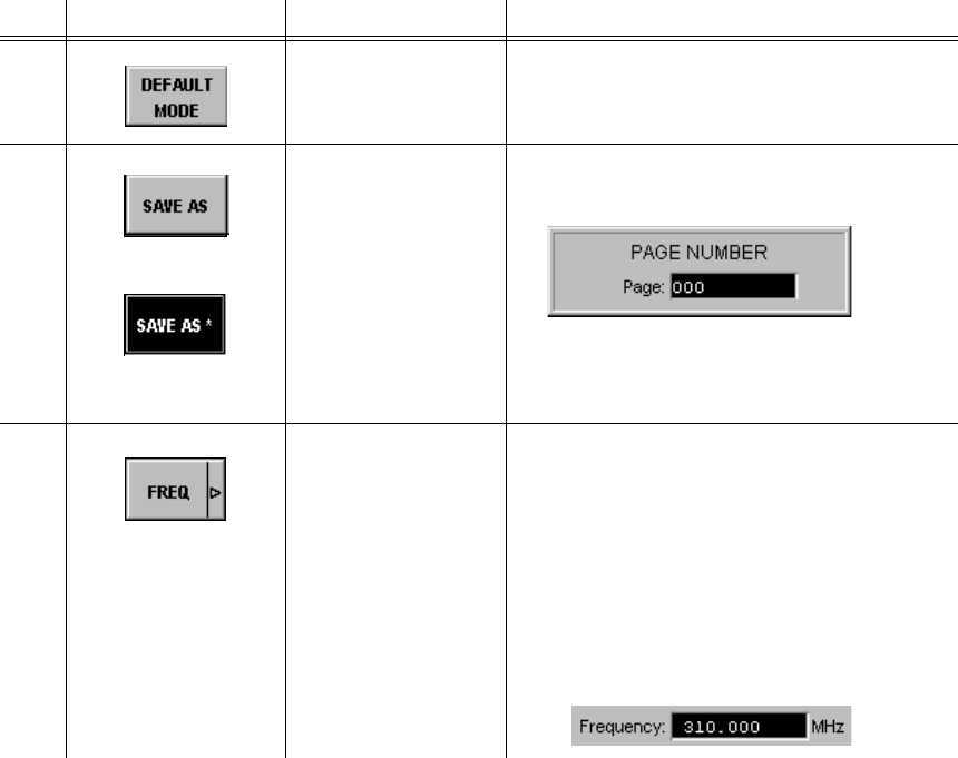
065 75$16&(,9(5 ; $ ; $
Operator’s Manual • Use under Special Conditions
– 3.68 – 6076.0822.12.01
7 Press softkey
DEFAULT MODE. Selection of the radio operation mode to
be set, if this Preset Page is called up.
8 Press softkey
SAVE AS.
Set value.
Press softkey
SAVE AS.
Saves the edited PRESET PAGE under a
new PRESET number.
Range of values: 0 to 199
The asterix (*) indicates that the new set-
tings have not yet been stored.
12 Press softkey
FREQ.
Set value.
Setting the frequency in the range from
q100 to 512 MHz
(VHF/UHF transceiver) or
q100 to 173.9875 MHz
(VHF transceiver) or
q225 to 399.9875 MHz
(UHF transceiver)
No. Control Action Notes
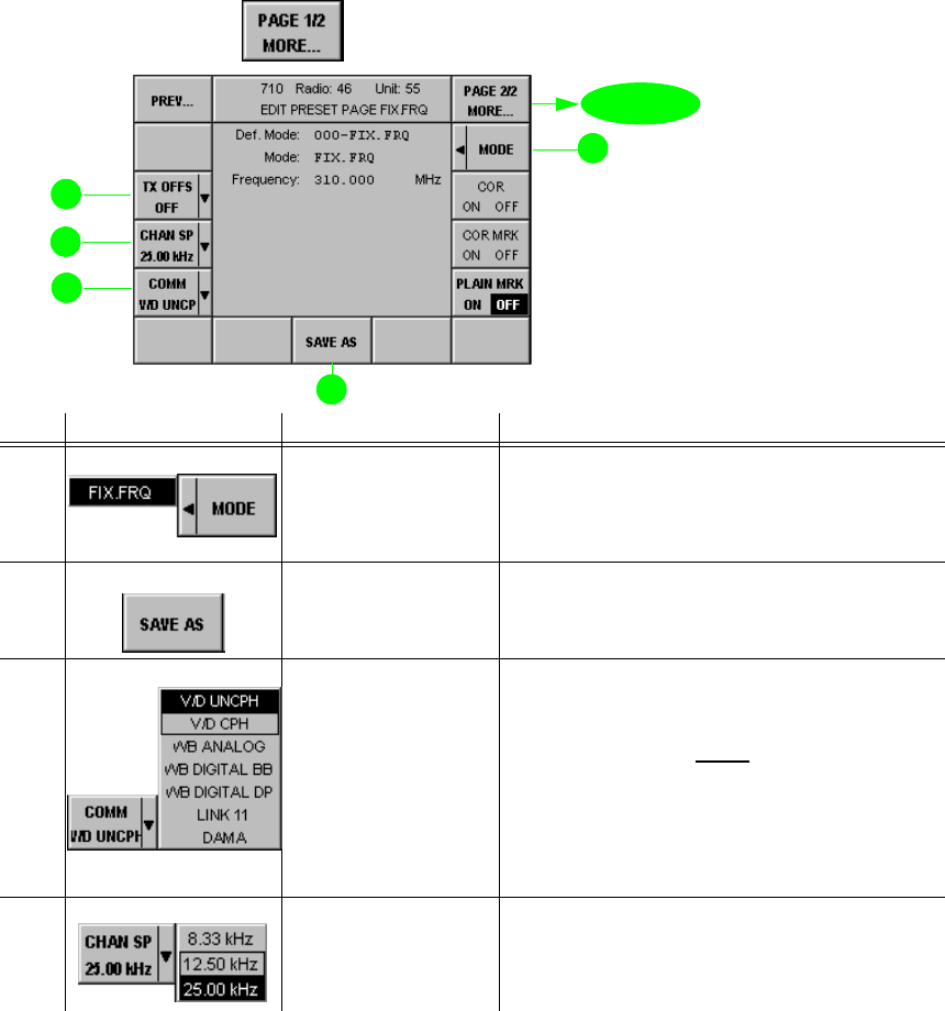
065 75$16&(,9(5 ; $ ; $
Operator’s Manual • Use under Special Conditions
6076.0822.12.01 – 3.69 –
0HQX3DJH(',735(6(73$*(),;)54)L[HG)UHTXHQF\
In this menu the settings of a Preset Page selected in Menu 620 (LOADED PRESET PARAMS)
are displayed, edited and stored (page 2 of 2).
Starting point: Menu 710, page 1
+Press softkey (1) and the following display appears:
No. Control Action Notes
2 See chapter 3.7.30, softkey 2.
8 See chapter 3.7.30, softkey 8.
11 Press softkey
COMM.
Select setting.
Selection of a pre-defined communication
mode
1RWH
:KHQDFRPPXQLFDWLRQPRGHQRWVXS
SRUWHGE\WKHUDGLR6:RSWLRQPLVVLQJGH
YLFHPDSSLQJLVVHWYLDWKH3UHVHW3DJHV
FRPPXQLFDWLRQPRGH9'81&3ZLOOEHDF
WLYDWHGE\GHIDXOW
12 Press softkey
CHAN SP.
Select setting.
Selection of the channel spacing
softkey PAGE 1/2 MORE...
page 1
0HQX
no function

065 75$16&(,9(5 ; $ ; $
Operator’s Manual • Use under Special Conditions
– 3.70 – 6076.0822.12.01
13 Press softkey
TX OFFS.
Select value.
Selection of the Tx offset value
See Menu 110, page 2 (MANUAL
FIX.FRQ).
No. Control Action Notes
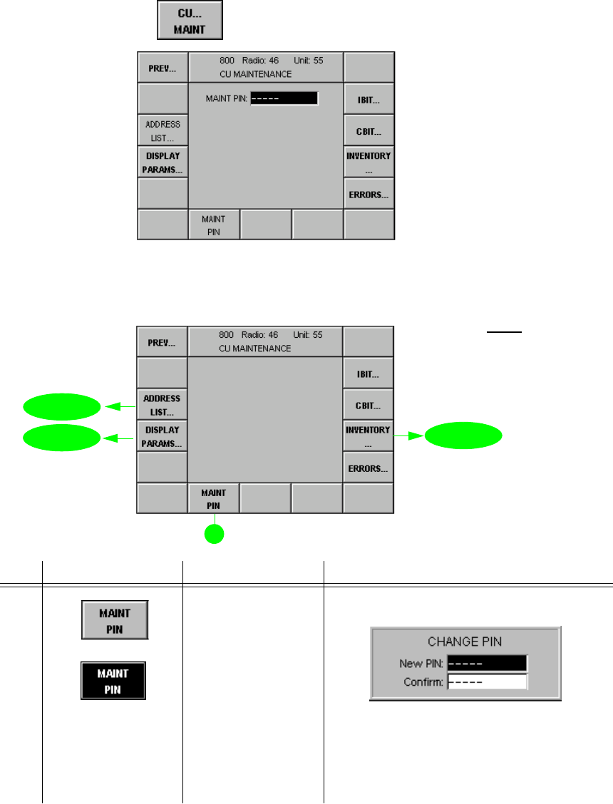
065 75$16&(,9(5 ; 0 ; 0
Operator’s Manual • Use under Special Conditions
6076.0851.12.01 – 3.71 –
0HQX&80$,17(1$1&(
In this menu the hardware and software parameters of the Control Unit GB 4000C are dis-
played and edited.
Starting point: Menu 040 (MAIN)
+Press softkey (6) and the following display appears:
+Enter control unit maintenance PIN number (5 digits) by using the numerical keypad, then
press ENTER.
qThe following display appears:
No. Control Action Notes
9 Press softkey
MAINT PIN.
Abort entry.
Entry of a new maintenance PIN
1. Enter the new PIN by using the numerical
keypad, then press ENTER.
2. Confirm the new PIN by repeating the entry
using the numerical keypad, then press EN-
TER.
See also chapter 3.6.
softkey CU... MAINT
0HQX
0HQX
0HQX
1RWH
6RIWNH\V,%,7&%,7DQG
(55256DUHGHVFULEHGLQ
FKDSWHU
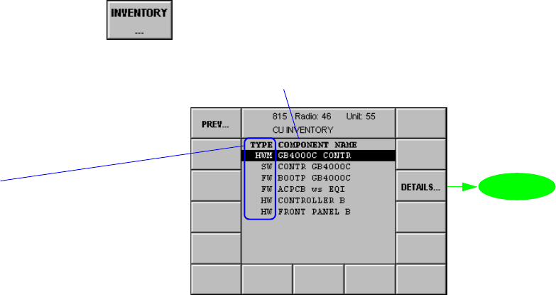
065 75$16&(,9(5 ; 0 ; 0
Operator’s Manual • Use under Special Conditions
– 3.72 – 6076.0851.12.02
0HQX&8,19(1725<
This menu gives an overview of the hardware, software and firmware components installed in
the control unit.
Starting point: Menu 800 (CU MAINTENANCE)
+Press softkey (4) and the following display appears:
softkey INVENTORY...
0HQX
Types:
SW - identifier for software
FW - identifier for firmware
HWM - identifier for hardware module
HW - identifier for hardware
see Appendix A1
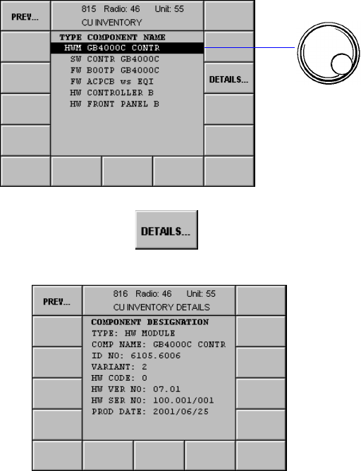
065 75$16&(,9(5 ; 0 ; 0
Operator’s Manual • Use under Special Conditions
6076.0851.12.02 – 3.73 –
0HQX&8,19(1725<'(7$,/6
This menu shows details about a component.
Starting point: Menu 815 (CU INVENTORY)
+Press softkey (3) and the following display appears (example):
+Select component.
softkey DETAILS...
The data for the component selected in
Menu 815 comprise the following:
Type (hardware, software,
firmware)
Name of module or software
Ident. No.
Variant
Code No.
Version No.
Serial No.
Production Date
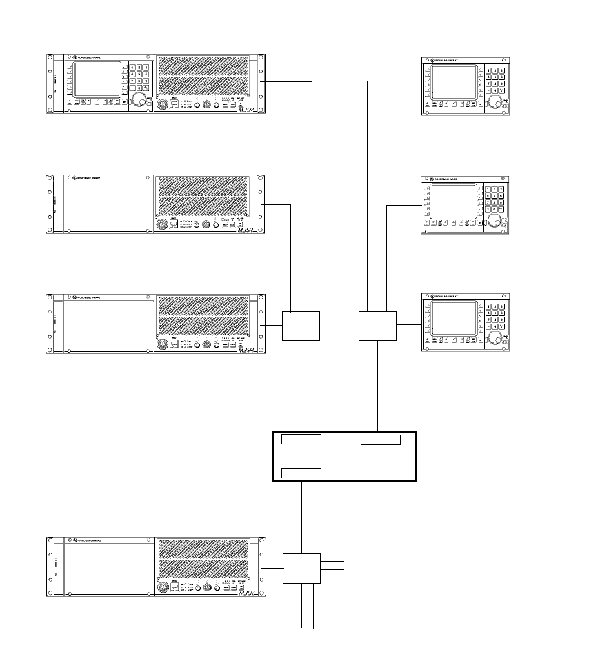
065 75$16&(,9(5 ; 0 ; 0
Operator’s Manual • Use under Special Conditions
– 3.74 – 6076.0851.12.01
0HQX5$',2$''5(66/,67
)LJ ([DPSOHRID1HWZRUNZLWK5RXWHU
5RXWHU
,3DGGUHVV/RJLFDODGGUHVV
5
&
,3DGGUHVV/RJLFDODGGUHVV
5
,3DGGUHVV/RJLFDODGGUHVV
5
,3DGGUHVV/RJLFDODGGUHVV
&
,3DGGUHVV/RJLFDODGGUHVV
&
,3DGGUHVV/RJLFDODGGUHVV
&
*DWHZD\DGGUHVV
*DWHZD\DGGUHVV
5UDGLR
&FRQWUROXQLW
Hub
,3DGGUHVV/RJLFDODGGUHVV
5
Hub
*DWHZD\DGGUHVV
*DWHZD\
*DWHZD\
*DWHZD\
Hub
HJIXUWKHUUDGLRV
HJIXUWKHUUDGLRV

065 75$16&(,9(5 ; 0 ; 0
Operator’s Manual • Use under Special Conditions
6076.0851.12.01 – 3.75 –
For addressing the M3SR devices the Internet Protocol (IP) is used. Therefore a unique IP ad-
dress needs to be assigned to each device, permitting the device to be identified and ad-
dressed without ambiguity. In addition, each device needs a freely selectable logical address
in the range from 000 to 999, which is the address to be entered in Menu 010 (RADIO CON-
NECTION) for addressed operation. The logical address spares the operator the tedious task
of entering the complex IP addresses.
Via Menu 835, the addresses (logical and IP addresses) of devices other than one’s own can
be entered or deleted. When entering the IP address please observe the IETF (= Internet En-
gineering Task Force) standards (RFC pages = request for comments). In compliance with
RFC1918, the following IP address ranges are reserved for private networks:
q10.0.0.0 to 10.255.255.255, associated subnet mask 255.0.0.0
q172.16.0.0 to 172.31.255.255, associated subnet mask 255.255.0.0
q192.168.0.0 to 192.168.0.255, associated subnet mask 255.255.255.0
The subnet mask defines the respective address parts for network address and local address.
1RWH
•,3DGGUHVVHVDQGDUHQRWSHUPLWWHGWREHXVHG
•)RUWKHQHWLQIUDVWUXFWXUHHJURXWHUZHUHFRPPHQGWRXVHWKHORZHUORFDODGGUHVVHV
Menu 835 displays all stored addresses. In Menu 010 (CU ADDRESS ROUTE) only those de-
vices can be selected to set up a link, which figure in the address list and which in column ’G’
are not marked with a ’-’ (wrong configuration, see Menu 836).
When a radio is selected whose network address (e.g. 192.168..010) differs from the con-
trol unit network address (e.g. 192.168..011), the link is set up via the router.
Network address Local address
Subnet mask 255 255 255 0
IP addresses 192 168 0 0
::::
192 168 0 255
max. 256 units
0 reserved for network
255 reserved for broadcas
t

065 75$16&(,9(5 ; 0 ; 0
Operator’s Manual • Use under Special Conditions
– 3.76 – 6076.0851.12.01
Example:
1. Defining the subnet mask
- depending on the number of networks and devices per network
(up to 256 networks with max. 253 devices per network => 255.255.255.000)
2. Defining the logical addresses and IP addresses
- Select a logical address that clearly identifies the particular device and is easy to re-
member.
- The logical and the local address may be identical.
3. Defining the gateway addresses
- For each local network a gateway address is required
(192.168.082.001, 192.168.083.001 and 192.168.084.001).
- For the local address always use "1".
4. Entering the logical addresses and IP addresses for those radios that are to be linked up
to
- We recommend to also enter the logical addresses and IP addresses of the control
units, because this will inhibit these addresses for radios and prevent multiple address
allocation.
5. Entering the own address, subnet mask and gateway address in Menu 836 (CU AD-
DRESS ROUTE)
Address
Logical Associated IP = network + local
46 192.168.082.010 192.168.082 010
47 192.168.082.011 192.168.082 011
48 192.168.082.012 192.168.082 012
50 192.168.083.010 192.168.083 010
51 192.168.083.011 192.168.083 011
52 192.168.083.012 192.168.083 012
55 192.168.082.020 192.168.082 020
68 192.168.084.010 192.168.084 010
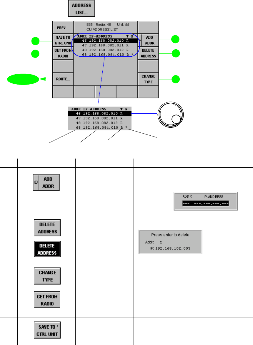
065 75$16&(,9(5 ; 0 ; 0
Operator’s Manual • Use under Special Conditions
6076.0851.12.02 – 3.77 –
Starting point: Menu 800, page 1 (CU MAINTENANCE)
+Press softkey (13) and the following display appears:
No. Control Action Notes
2 Press softkey ADD
ADDR.
Enter
Adds address to the address list. Entry of
logical address and IP address for another
device:
3 Press softkey
DELETE
ADDRESS.
Abort process.
Deletes the selected address.
5 Press softkey
CHANGE TYPE. Switches over between radio and controller
(control unit).
13 Press softkey GET
FROM RADIO. Retrieves an address list from the assigned
radio (see also Menu 435 (RADIO AD-
DRESS LIST)). In this way the control unit
obtains all addresses stored in the radio.
14 Press softkey SAVE
TO CTRL UNIT. Saves address list to the control unit.
The asterisk (*) indicates that the new set-
tings have not yet been stored.
softkey ADDRESS LIST...
0HQX
Logical address Type of device:
5 UDGLR
& UHPRWHFRQWUROXQLW
Gateway:
EODQN GHYLFHLVSDUWRIWKHORFDOQHWZRUN
GHYLFHLVSDUWRIDQRWKHUQHWZRUN
WREHUHDFKHGYLDDJDWHZD\
ZURQJFRQILJXUDWLRQVHH0HQX
+Select address.
IP address
1RWH
:KHQVRIWNH\*(7
)5205$',2LV
SUHVVHGDQ\H[LVWLQJDG
GUHVVHVZLOOEHUHSODFHG
7KLVSUHYHQWVWKDWLGHQWL
FDO,3DGGUHVVHVZLWKGLI
IHUHQWORJLFDODGGUHVVHV
DUHFUHDWHG
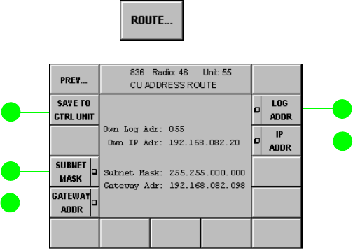
065 75$16&(,9(5 ; 0 ; 0
Operator’s Manual • Use under Special Conditions
– 3.78 – 6076.0851.12.01
0HQX&8$''5(665287(
Via Menu 836 the own address (logical and IP address) can be entered. When specifying the
Subnet Mask and the IP addresses (own and Gateway), please observe the IETF standards
(RFC pages), in particular:
q796: Address Mappings
q940: Toward an Internet Standard Scheme for Subnetting
q950: Internet Standard Subnetting Procedure
q1219: On the Assignment of Subnet Numbers
q1517: Applicability Statement for the Implementation of Classless Inter-Domain
Routing
q1519: Classless Inter-Domain Routing: an Address Assignment and Aggregation
Strategy
q1918: Address Allocation for Private Internets
In compliance with RFC1918 the following address ranges are reserved for private networks:
q10.0.0.0 to 10.255.255.255, associated subnet mask 255.0.0.0
q172.16.0.0 to 172.31.255.255, associated subnet mask 255.255.0.0
q192.168.0.0 to 192.168.255.255, associated subnet mask 255.255.255.0
Starting point: Menu 835 (CU ADDRESS LIST)
+Press softkey (11) and the following display appears:
softkey ROUTE...
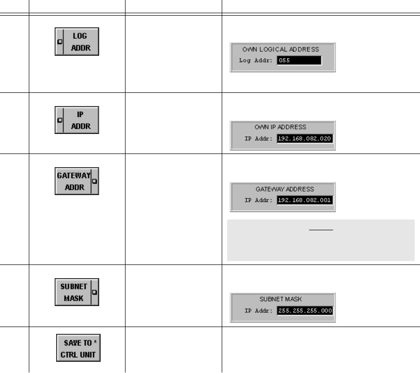
065 75$16&(,9(5 ; 0 ; 0
Operator’s Manual • Use under Special Conditions
6076.0851.12.01 – 3.79 –
No. Control Action Notes
2 Press softkey
LOG ADDR.
Change value.
Changing the own logical address:
Range of values: 001 to 999
3 Press softkey
IP ADDR
Change value.
Changing of the own IP address:
11 Press softkey
GATEWAY ADDR.
Change value.
Changing the gateway address:
12 Press softkey
SUBNET MASK.
Change value.
Changing the subnet mask:
14 Press softkey SAVE
TO CTRL UNIT. Saves address list to the control unit.
The asterisk (*) indicates that the new set-
tings have not yet been stored.
1RWH
(QWU\RIGHOHWHVDQH[
LVWLQJJDWHZD\DGGUHVV
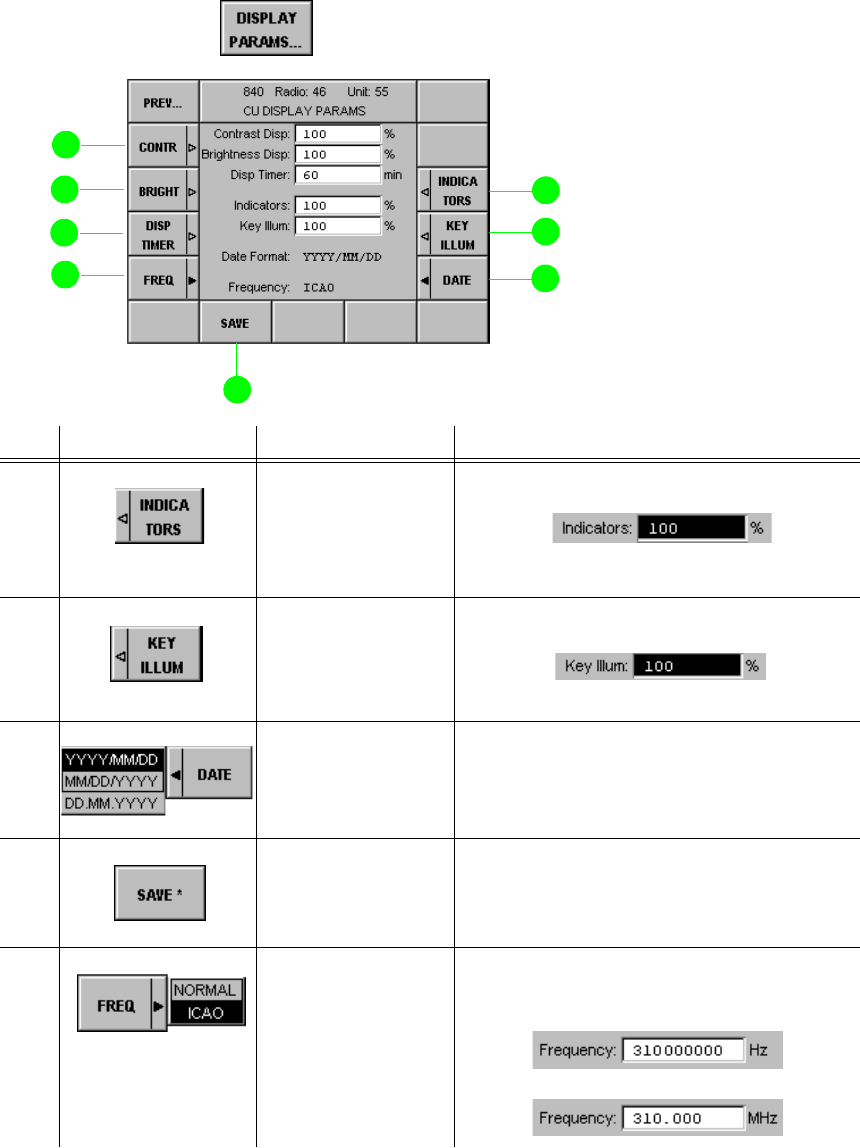
065 75$16&(,9(5 ; 0 ; 0
Operator’s Manual • Use under Special Conditions
– 3.80 – 6076.0851.12.01
0HQX&8',63/$<3$5$06
In this menu the display parameters of the control unit are displayed and edited.
Starting point: Menu 800 (CU MAINTENANCE)
+Press softkey (6) and the following display appears:
No. Control Action Notes
3 Press softkey
INDICATORS.
Set value.
Setting the LED brightness
Permitted range of values: 0% to 100%
4 Press softkey KEY
ILLUM.
Set value.
Setting the front key illumination
Permitted range of values: 0% to 100%
5 Press softkey
DATE.
Select format.
Selection of the date format
9 Press softkey
SAVE. Saves the current configuration.
The asterisk (*) indicates that the new set-
tings have not yet been stored.
11 Press softkey
FREQ.
Select setting.
Selection of the frequency mode
NORMAL:
ICAO:
softkey DISPLAY PARAMS...

065 75$16&(,9(5 ; 0 ; 0
Operator’s Manual • Use under Special Conditions
6076.0851.12.01 – 3.81 / 3.82 –
12 Press softkey
DISP TIMER.
Set value.
Setting of the display timer in the range of
1 to 60 minutes (display goes blank).
Permitted range of values: 0 to 60 min.
After this timeout the display goes blank.
13 Press softkey
BRIGHT.
Set value.
Setting of the display brightness in per-
cent.
Permitted range of values: 0% to 100%
14 Press softkey
CONTR.
Set value.
Setting the display contrast in percent.
Permitted range of values: 0% to 100%
No. Control Action Notes
Frequency
(MHz) Channel
spacing
(kHz)
Channel
xxx.0000 25 xxx.000
xxx.0000 8.33 xxx.005
xxx.0083 8.33 xxx.010
xxx.0167 8.33 xxx.015
xxx.0250 25 xxx.025
xxx.0250 8.33 xxx.030
xxx.0333 8.33 xxx.035
xxx.0417 8.33 xxx.040
xxx.0500 25 xxx.050
xxx.0500 8.33 xxx.055
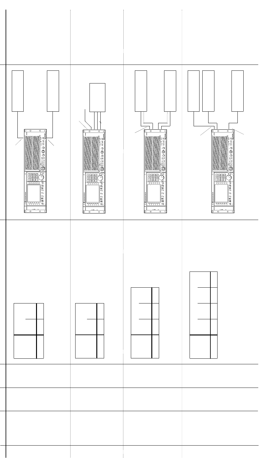
065 75$16&(,9(5 ; $ ; $
Operator’s Manual • Operation under Special Conditions
6076.0822.12.01 – 3.83 / 3.84 –
Radio oper-
ation mode
Communication
mode
V/D
UNCP V/D
CP
FIX.FRQ [[
NB1
PTT_1L Audio System
WB2
PTT_2L
AF Interface 1
(X26)
AF Interface 2
(X25)
Analog Data
Equipment
NB1
PTT_1L
WB1
AF Interface 1
(X26)
Audio System
e.g.
16-kbps Cipher Unit
e.g.
Link 11 Unit (DTS)
NB1
PTT_1L
WB1
PTT_1
AF Interface 1
(X26)
NB2
PTT_2
AF Interface 2
(X25)
Audio System
e.g.
16-kbps Cipher Unit
NB1
PTT_1L
WB1
PTT_1
AF Interface 1
(X26)
Radio oper-
ation mode
Communication mode
V/D
UNCP WB
DIGITAL
BB
WB
DIGITAL
DP
LINK11
FIX.FRQ [[[[
Communication Mode
qVoice / Data
unciphered
qWideband analog
qVoice / Data
unciphered
qVoice / Data
ciphered
qVoice / Data
unciphered
qWideband digital
baseband
qWideband digital
diphase
qVoice / Data
unciphered
qWideband digital
baseband
qWideband digital
diphase
qLink11
Radio oper-
ation mode
Communication mode
V/D
UNCP WB
DIGITAL
BB
WB
DIGITAL
DP
FIX.FRQ [[[
Radio oper-
ation mode
Communication
mode
V/D
UNCP WB
ANALOG
FIX.FRQ [[
Keyline
PTT_1L
PTT_2L
PTT_1L
PTT_1L
PTT_1
PTT_1L
PTT_1
PTT_2
'HIDXOW
Device
none
CIPHER UNIT
SYNC WB DATA
SYNC WB DATA
LINK11
Audio line
NB1
WB2
NB1
WB1
NB1
WB1
NB1
WB1
NB2
Cipher Unit
KY58
CGC
DPTT
PT/CT
BB/DP
Zeroize
%RWKNH\OLQHVDUHHQDEOHGIRUERWKFRPPXQLFDWLRQPRGHV(JNH\OLQH377B/DFWLYDWHVWUDQVFHLYHU
LQ9'81&3DQG:%$1$/2*
)LJ$SSOLFDWLRQ([DPSOHVHJ;7 $
065 75$16&(,9(5 ; $ ; $
Operator’s Manual • Malfunction
6076.0822.12.01 – 4.1 –
0DOIXQFWLRQ
,QWURGXFWLRQ
This chapter provides information concerning
qVisual Inspection
qTroubleshooting
- BIT Design
- BIT Radio (Menu RADIO MAINTENANCE)
- BIT Control Unit (Menu CU MAINTENANCE)
9LVXDO,QVSHFWLRQ
Check the following:
1. Check external cabling between the complete transceiver and external equipment.
2. Check all connectors for firm seating and the power supply cable and RF coaxial cables
at the rear for mechanical damage. If necessary, replace cables by new ones one at a
time until the defective connection has been found.
&$87,21
,IDFRQQHFWRUVKRZVDQ\GLVFRORXUDWLRQFDXVHGE\KHDWLWVPDWLQJFRQQHFWRULVDOVR
GHIHFWLYHDQGPXVWEHUHSODFHGWRR
Obvious damage of minor importance can be eliminated on the spot, provided that the appro-
priate equipment is available. In case of severe damage, the transceiver must be sent to the
nearest repair facility.
065 75$16&(,9(5 ; $ ; $
Operator’s Manual • Malfunction
– 4.2 – 6076.0822.12.01
7URXEOHVKRRWLQJ
Troubleshooting of the remote-controlled transceiver is possible by using for instance a Control
Unit GB 4000C, mod. 03.
%,7'HVLJQ
For detection of device and system failures Built-In Test (BIT) functions are implemented in the
equipment.
The BIT functions support the service team in detecting and analysing equipment and system
errors, helping them to decide on appropriate countermeasures.
qPBIT
The Power-on BIT is performed automatically after power supply has been switched
on.
qCBIT
The Continuous BIT starts directly after PBIT.
The system is subjected to a functional check.
The modules installed in the radio basis are continuously checked by CBIT.
Warnings and/or error messages produced during ongoing operation are displayed in
Menu 410 (RADIO CBIT RESULTS) for the transceiver and in Menu 810 (CU CBIT RE-
SULTS) for the control unit.
As long as an error is indicated in Menu 410 (RADIO CBIT RESULTS), the GO LED
remains dark and connector contact X23.4 (NOGO) carries low level.
Menu 420 (RADIO ERROR LIST) or 820 (CU ERROR LIST) displays all warnings and
error messages that have occurred, together with the time of occurrence.
When malfunctions (warning or error message) have been detected, the failure is sig-
nalled to the control unit and/or via GB2PP protocol to a connected remote control unit.
qIBIT
The Initiated BIT is used for equipment diagnostics (test of LEDs, RF wiring etc.). IBIT
helps to localize failures and to support maintenance.
It can be activated directly on the local control unit (Menu 405 (RADIO IBIT RESULTS))
and also by a remote control command (only GB2PP protocol).
It takes several minutes for IBIT to be completed. It is possible to interrupt this test any
time and to continue later.
During IBIT the transceiver is not available for operation.
Please note that the radio is only ok if CBIT and IBIT both signal GO.
The rating of a BIT message can be either warning or error, depending on how serious the trou-
ble is.
qWhen there is a warning, operation may still go on, although the radio should be checked
as soon as possible. The GO LED remains lighted in the presence of warnings.
qWhen an error is indicated, the radio is not working correctly and needs to be sent to the
next repair facility. The GO LED is extinguished in the presence of errors, and contact
X23.4 changes to low level.
Irrespective of the rating, a BIT message is reported in Menu 410 (RADIO CBIT RESULTS)
and/or Menu 420 (RADIO ERROR LIST). Please take care: the RADIO ERROR LIST contains
both errors and warnings.
CBIT always indicates the existing state, that means, as long as a BIT message is being indi-
cated by CBIT, this problem persists.
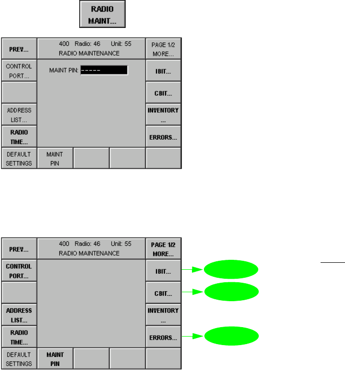
065 75$16&(,9(5 ; $ ; $
Operator’s Manual • Malfunction
6076.0822.12.01 – 4.3 –
%,75DGLR
0HQX3DJH5$',20$,17(1$1&(
Via this menu the maintenance functions implemented in the radio are activated.
Starting point: Menu 040 (MAIN)
+Press softkey (4) and the following display appears:
+Enter maintenance PIN (5 digits) by using the numerical keypad, then press ENTER.
qThe following display appears:
+Press the relevant softkey to call up any of these menus.
softkey RADIO MAINT...
0HQX
0HQX
0HQX
1RWH
6RIWNH\V,19(1725<
0$,173,1'()$8/7
6(77,1*65$',2
7,0($''5(66
/,67DQG&21752/
3257DUHGHVFULEHGLQ
FKDSWHU

065 75$16&(,9(5 ; $ ; $
Operator’s Manual • Malfunction
– 4.4 – 6076.0822.12.01
0HQX5$',2,%,75(68/76
In this menu, an IBIT (Initiated Built-In Test) for the entire radio or a selected Comline can be
started. After completion of IBIT the results are displayed.
Starting point: Menu 400, page 1 (RADIO MAINTENANCE)
+Press softkey (2) and the following display appears:
1RWH
3HUIRUP,%,7RQO\XQGHUWKHIROORZLQJFRQGLWLRQV
•5DGLRRSHUDWLRQPRGH),;)54
•0RGXODWLRQPRGH$0
•&RPPXQLFDWLRQPRGH9'81&3YRLFHGDWDXQFLSKHUHG
•0DNHVXUHWKDWWKHIXOO9'&VXSSO\YROWDJHLVDYDLODEOHDWDOOWLPHVRWKHUZLVHWKHUH
TXLUHGWUDQVPLWSRZHUZLOOIDLOWREHREWDLQHGDQGDUHODWLQJ%,7ZDUQLQJZLOOEHSURGXFHG
,IWKHVHUHTXLUHPHQWVDUHQRWPHWDQHUURUPHVVDJHPD\FRPHXSZKHQWKH,%,7LVVWDUWHG
2QFHWKH,%,7LVFRPSOHWHGUHVHWWKHUDGLRNH\212))3OHDVHQRWHWKDWGXULQJ,%,7ORZ
SRZHUWUDQVPLWVLJQDOVDUHUDGLDWHG
As soon as IBIT signals anything other than GO, IBIT needs to be repeated. If the same error
persists, send the radio to the depot for repair.
No. Control Action Notes
2 Press softkey
EQUIP.
Select equipment.
Selection of equipment for IBIT
$//all components installed
&/components of Comline CL1
1RWH
(UURUPHVVDJHVUHVXOWLQJIURP,%,7DUHGLV
SOD\HGVHOHFWLYHO\GHSHQGLQJRQWKHVH
OHFWHGHTXLSPHQW
9 Press softkey
START.
Terminate IBIT with
softkey STOP.
Starts IBIT for the selected configuration.
1RWH
,%,7FDQEHVWRSSHGDQ\WLPH
softkey IBIT...
1RWH
6RIWNH\'(7$,/6LVRQO\
HQDEOHGZLWKVWDWXV(55
0HQX
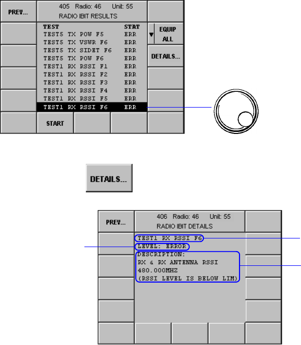
065 75$16&(,9(5 ; $ ; $
Operator’s Manual • Malfunction
6076.0822.12.01 – 4.5 –
0HQX5$',2,%,7'(7$,/6
This menu displays information about an IBIT result.
Starting point: Menu 405 (RADIO IBIT RESULTS)
+Press softkey (3) and the following display appears:
ÇSee also Menu 420 (RADIO ERROR LIST) and Menu 421 (RADIO ERROR DETAILS).
+Select message.
softkey DETAILS...
Message
Explanation of
message
Status:
Warning or Error
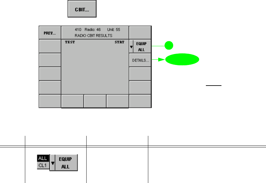
065 75$16&(,9(5 ; $ ; $
Operator’s Manual • Malfunction
– 4.6 – 6076.0822.12.01
0HQX5$',2&%,75(68/76
This menu provides information about the CBIT (Continuous Built-In Test) results. It displays
all currently existing warnings and/or errors. As long as an error persists, the GO LED is extin-
guished and contact X23.4 (NOGO) carries low level.
Starting point: Menu 400, page 1 (RADIO MAINTENANCE)
+Press softkey (3) and the following display appears:
No. Control Action Notes
2 Press softkey
EQUIP.
Select equipment.
Selection of equipment for CBIT
$//all components installed
&/components of Comline CL1
softkey CBIT...
0HQX
1RWH
6RIWNH\'(7$,/6LVRQO\
HQDEOHGZLWKVWDWXV(55

065 75$16&(,9(5 ; $ ; $
Operator’s Manual • Malfunction
6076.0822.12.01 – 4.7 –
0HQX5$',2&%,7'(7$,/6
This menu displays information about a CBIT result.
Starting point: Menu 410 (RADIO CBIT RESULTS)
+Press softkey (3) and the following display appears:
ÇSee also Menu 420 (RADIO ERROR LIST) and Menu 421 (RADIO ERROR DETAILS).
+Select message.
softkey DETAILS...
Message
Explanation of
message
Status:
Warning or Error
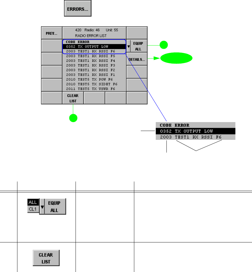
065 75$16&(,9(5 ; $ ; $
Operator’s Manual • Malfunction
– 4.8 – 6076.0822.12.01
0HQX5$',2(5525/,67
This menu selectively displays all messages (warnings and errors) which have occurred in the
radio, depending on the selected equipment. The first list entry always refers to the most recent
error. Up to 100 errors may be listed. When the error list is full, a warning message comes up
prompting the operator to clear the error list. Failure to do so will close the error list for new
entries.
Starting point: Menu 400, page 1 (RADIO MAINTENANCE)
+Press softkey (5) and the following display appears:
No. Control Action Notes
2 Press softkey
EQUIP.
Select equipment.
Selection of equipment for error list
$//all components installed
&/components of Comline CL1
Depending on the selection, all errors or
only those concerning CL1 are listed.
9 Press softkey
CLEAR LIST. Clears the complete error list in Menu
420.
softkey ERRORS...
0HQX
The latest error
Error code
number Error message
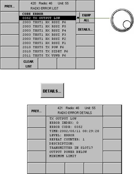
065 75$16&(,9(5 ; $ ; $
Operator’s Manual • Malfunction
6076.0822.12.01 – 4.9 –
0HQX5$',2(5525'(7$,/6
This menu shows the details of an error.
Starting point: Menu 420 (RADIO ERROR LIST)
+Press softkey (3) and the following display appears:
The details of an error selected in Menu 420 comprise the following data:
Name of error
Error index Consecutive error number in the radio error list
Error Code See Error Code List in chapter 4.3.2.8
Comline Comline No.
Time Time and date of error occurrence
Level Classification of failure: error or warning
Repeat Counter Number of occurrences
Description Description of failure
+Select error message
.
softkey DETAILS...

065 75$16&(,9(5 ; $ ; $
Operator’s Manual • Malfunction
– 4.10 – 6076.0822.12.01
(UURU/LVW
Check the error code and proceed as indicated in the Action column (in most cases the radio
will need to be transferred to the nearest depot facility).
1RWH
(UURUFRGHV[[[DUHQRWOLVWHGLQWKHWDEOH,I,%,7VHHFKDSWHUUHWXUQVD[[[HUURU
FRGH,%,7PXVWEHUHSHDWHG,IWKHHUURUSHUVLVWVVHQGWKHUDGLRWRWKHGHSRW
Code Message Level Notes Action
(CBIT message,
frequent or single event)
0001 GR CNAPI ERR W Inform depot.
0002 GR General Software Error W Inform depot.
0003 GR ERR STR FULL W Error store full Inform depot.
0004 GR FLASH CHCKS ERR E Checksum error of Flash
EEPROM Inform depot.
0100 PL +2.5 V LOW E Platform error:
+25-V reference voltage
low
Send radio to depot.
0101 PL V_BATT LOW W Platform warning:
33-V battery low Send radio to depot
(replace the platform battery).
0102 PL V_RET LOW E Platform error:
Retention voltage low Send radio to depot.
0103 PL INT +10V LOW E Platform error:
Internal voltage +10 V low Send radio to depot.
0105 PL INT -10V LOW E Platform error:
Internal voltage -10 V low Send radio to depot.
0106 PL OVERTEMP W Platform warning:
Overtemperature Check airflow of fans and ambient
temperature. If this fails to eliminate
the fault, send radio to depot.
0150 PL SRAM BATT EMPTY W Platform warning:
SRAM battery is low Send radio to depot
(replace the platform SRAM battery).
0200 PS -12V LOW E DC power supply error:
Voltage -12 V low CBIT message or frequent event:
Send radio to depot.
Single event:
no action
0201 PS +3.3V LOW E DC power supply error:
Voltage +33 V low CBIT message or frequent event:
Send radio to depot.
Single event:
no action
0202 PS +5V LOW E DC power supply error:
Voltage +5 V low CBIT message or frequent event:
Send radio to depot.
Single event:
no action
0203 PS +12V LOW E DC power supply error:
Voltage +12 V low CBIT message or frequent event:
Send radio to depot.
Single event:
no action
0204 PS +33V LOW E DC power supply error:
Voltage +33 V low CBIT message or frequent event:
Send radio to depot.
Single event:
no action

065 75$16&(,9(5 ; $ ; $
Operator’s Manual • Malfunction
6076.0822.12.01 – 4.11 –
0205 PS MAIN VLT LOW W DC power supply warning:
Main voltage (28 VDC) low CBIT message:
Send radio to depot.
Frequent event:
Check configuration (Menu 511, func-
tion PWR SUP). Switch off and check
external power supply, cables and
connectors at X31. If this fails to elimi-
nate the fault, send the radio to depot.
Single event:
Check configuration (Menu 511, func-
tion PWR SUP). Switch off and check
external power supply, cables and
connectors at X31.
0206 PS BATT VLT LOW W DC power supply warning:
Battery voltage low CBIT message:
Send radio to depot.
Frequent event:
Check configuration (Menu 511, func-
tion PWR SUP). Switch off and check
external power supply, cables and
connectors at X31. If this fails to elimi-
nate the fault, send the radio to depot.
Single event:
Check configuration (Menu 511, func-
tion PWR SUP). Switch off and check
external power supply, cables and
connectors at X31.
0207 PS VLT LW VLIM W DC power supply warning:
VLIM voltage low CBIT message or frequent event:
Send radio to depot.
Single event:
no action
0208 PS VLT EXT SW W DC power supply warning:
Voltage for external switch
low
CBIT message or frequent event:
Send radio to depot.
Single event:
no action
0209 PS 28V LT AMP LOW DC W DC power supply warning:
28 VDC for left amplifier
low
CBIT message or frequent event:
Send radio to depot.
Single event:
no action
0210 PS 28V RT AMP LOW DC W DC power supply warning:
28 VDC for right amplifier
low
CBIT message or frequent event:
Send radio to depot.
Single event:
no action
0211 PS 28V DRV AMP LOW W DC power supply warning:
28 VDC for driver amplifier
low
CBIT message or frequent event:
Send radio to depot.
Single event:
no action
0212 PS VLT PAX LW VLIM W DC power supply warning
Voltage power amplifier
below limit
CBIT message or frequent event:
Send radio to depot.
Single event:
no action
0213 PS OVERTEMP W DC power supply warning:
Overtemperature in power
supply unit
CBIT message or frequent event:
Check airflow of fans and ambient
temperature. If this fails to eliminate
the fault, send radio to depot.
Single event:
Check airflow of fans and ambient
temperature.
Code Message Level Notes Action
(CBIT message,
frequent or single event)

065 75$16&(,9(5 ; $ ; $
Operator’s Manual • Malfunction
– 4.12 – 6076.0822.12.01
0214 PS SPEED FAN1 LOW W DC power supply warning:
Speed of fan 1 at trans-
ceiver rear is too low
CBIT message or frequent event:
Check airflow of fans and ambient
temperature. If this fails to eliminate
the fault, send radio to depot.
Single event:
Check airflow of fans and ambient
temperature.
0215 PS SPEED FAN2 LOW W DC Power supply warning:
Speed of fan 2 at trans-
ceiver rear is too low
CBIT message or frequent event:
Check airflow of fans and ambient
temperature. If this fails to eliminate
the fault, send radio to depot.
Single event:
Check airflow of fans and ambient
temperature.
0216 PS DC UNDER VOLT W DC power supply warning:
External DC supply under
18 VDC
CBIT message or frequent event:
Switch off and check external AC/DC
Power Supply IN 4000A, cables and
connectors. If this fails to eliminate the
fault, send radio to depot.
Single event:
Switch off and check external AC/DC
Power Supply IN 4000A, cables and
connectors.
0217 PS NO SYNC E DC power supply error:
External 100-kHz reference
not present
CBIT message or frequent event:
Send radio to depot.
Single event:
no action
0218 PS OVERTEMP AC/DC W DC power supply warning:
Overtemperature in exter-
nal Power Supply
IN 4000A
CBIT message or frequent event:
Switch off and check external AC/DC
Power Supply IN 4000A, cables and
connectors. If this fails to eliminate the
fault, send radio to depot.
Single event:
Switch off and check external AC/DC
Power Supply IN 4000A, cables and
connectors.
0250 SY DEF E Synthesizer error:
Module defective CBIT message or frequent event:
Send radio to depot.
Single event:
no action
0251 SY VOLT ERR E Synthesizer error:
Voltage error CBIT message or frequent event:
Send radio to depot.
Single event:
no action
0252 SY SYNC E Synthesizer error:
Synchronization error / bad
time reference
CBIT message or frequent event:
Send radio to depot.
Single event:
no action
0253 SY EXT FREQ REF E Synthesizer error:
Not locked to an external
reference
CBIT message or frequent event:
Send radio to depot.
Single event:
no action
0254 SY LEV LO OSC E Synthesizer error:
Local oscillator level low CBIT message or frequent event:
Send radio to depot.
Single event:
no action
0255 SY SYNC ERR E Synthesizer error:
Synchronization/timing
error
CBIT message or frequent event:
Send radio to depot.
Single event:
no action
Code Message Level Notes Action
(CBIT message,
frequent or single event)

065 75$16&(,9(5 ; $ ; $
Operator’s Manual • Malfunction
6076.0822.12.01 – 4.13 –
0256 SY PLL UNLOCK E Synthesizer error:
PLL unlock CBIT message or frequent event:
Send radio to depot.
Single event:
no action
0257 SY FREQ CMD ERR W Synthesizer warning:
Incorrect frequency value
commanded
Inform depot.
270 HSELU FREQ CMD ERR W UHF filter warning:
Illegal frequency value
commanded
Inform depot.
271 HSELU NO OUTPOW E UHF filter error:
No output power. The error
message disappears after
the next faultless transmis-
sion.
CBIT message or frequent event:
Send radio to depot.
Single event:
no action
272 HSELU NO INPOW E UHF filter error:
No input power. The error
message disappears after
the next faultless transmis-
sion.
CBIT message or frequent event:
Send radio to depot.
Single event:
no action
273 HSELU VOLT ERR E UHF filter error:
Voltage error CBIT message or frequent event:
Send radio to depot.
Single event:
no action
274 HSELU DEFECT E UHF filter error:
UHF filter defective CBIT message or frequent event:
Send radio to depot.
Single event:
no action
0300 RX OVERTEMP W Receiver warning:
Overtemperature in module CBIT message or frequent event:
Check airflow of fans and ambient
temperature. If this fails to eliminate
the fault, send radio to depot.
Single event:
Check airflow of fans and ambient
temperature.
0301 RX EXT REF NOT PRES E Receiver error:
External 100-kHz reference
frequency not present
CBIT message or frequent event:
Send radio to depot.
Single event:
no action
0302 RX IF PART OVERLOAD E Receiver error:
IF part overload CBIT message or frequent event:
Send radio to depot.
Single event:
no action
0303 RX IN SIG OVERLOAD W Receiver warning:
Input signal overload CBIT message or frequent event:
Receive signal too large. Switch off
and check RF cables. If this fails to
eliminate the fault, send radio to
depot.
Single event:
Receive signal too large. Switch off
and check RF cables.
0304 RX GEN ERR E Receiver error:
General error CBIT message or frequent event:
Send radio to depot.
Single event:
no action
0305 RX WATCHDOG E Receiver error:
Reset of µP caused by
watchdog circuit
Send radio to depot.
Code Message Level Notes Action
(CBIT message,
frequent or single event)

065 75$16&(,9(5 ; $ ; $
Operator’s Manual • Malfunction
– 4.14 – 6076.0822.12.01
0306 RX INT REF DEF E Receiver error:
Internal reference defective Send radio to depot.
0307 RX IF PART DEF E Receiver error:
IF part defective Send radio to depot.
0308 RX INT LO DEF E Receiver error:
Internal local oscillator
defective
CBIT message or frequent event:
Send radio to depot.
Single event:
no action
0309 RX EXT LO NOT PRES E Receiver error:
External local oscillator not
present
CBIT message:
Send radio to depot.
frequent event:
Switch off and check RF cables. If this
fails to eliminate the fault, send radio
to depot.
Single event:
no action
0350 TX GLOBAL ERROR E Transmitter error:
TX is switched off due to
global error in module
Send radio to depot.
0351 TX PIN DIODE SW DEF E Transmitter error:
PIN diode switch defective Send radio to depot.
0352 TX OUTPUT LOW E Transmitter error:
Output power below mini-
mum limit
CBIT message or frequent event:
Send radio to depot.
Single event:
no action
0353 TX OUTPUT HIGH E Transmitter error:
Output power above maxi-
mum limit
CBIT message or frequent event:
Send radio to depot.
Single event:
no action
0354 TX OVERTEMP W Transmitter warning:
Tx is switched off due to
overtemperature in module
CBIT message or frequent event:
Check airflow of fans and ambient
temperature. If this fails to eliminate
the fault, send radio to depot.
Single event:
Check airflow of fans and ambient
temperature.
0355 TX WATCHDOG E Transmitter error:
Reset of µP caused by
watchdog circuit
Send radio to depot.
0356 TX INCORR CMD E Transmitter error:
Received command is not
correct
Send radio to depot.
0357 TX OVERVOLTAGE W Transmitter warning:
Overvoltage CBIT message or frequent event:
Switch off and check DC power sup-
ply. If this fails to eliminate the fault,
send radio to depot.
Single event:
Switch off and check DC power sup-
ply.
0358 TX EXT REF NOT PRES E Transmitter error:
External 100-kHz reference
is not present
CBIT message or frequent event:
Send radio to depot.
Single event:
no action
0359 TX VSWR W Transmitter warning:
Voltage standing-wave
ratio above limit
Switch off and check antenna cabling.
If this fails to eliminate the fault, send
radio to depot.
Code Message Level Notes Action
(CBIT message,
frequent or single event)

065 75$16&(,9(5 ; $ ; $
Operator’s Manual • Malfunction
6076.0822.12.01 – 4.15 –
0360 TX IN DRIVE MISSING E Transmitter error:
Input drive signal below
limit or missing
CBIT message or frequent event:
Send radio to depot.
Single event:
no action
0361 TX POW CTL LOOP LIM E Transmitter error:
Power control loop out of
limits
CBIT message or frequent event:
Send radio to depot.
Single event:
no action
0362 TX POW REDUCED W Transmitter warning:
Output power reduced Check airflow of fans, ambient tem-
perature, antenna cabling and DC
power supply. If this fails to eliminate
the fault, send radio to depot.
0363 TX TEMP SENS SH E Transmitter error:
Temperature sensor is
shorted / defective
Inform depot.
0400 GRX WATCHDOG E Guard receiver error:
Reset of µP caused by
watchdog circuit
Send radio to depot.
0401 GRX EXT REF NOT PRE E Guard receiver error:
External 100-kHz reference
is not present
CBIT message or frequent event:
Send radio to depot.
Single event:
no action
0402 GRX VCO1 NOT LOCKED E Guard receiver error:
Loop of VCO1 (Voltage-
Controlled Oscillator) not
locked
CBIT message or frequent event:
Send radio to depot.
Single event:
no action
0403 GRX VCO2 NOT LOCKED E Guard receiver error:
Loop of VCO2 (Voltage-
Controlled Oscillator) not
locked
CBIT message or frequent event:
Send radio to depot.
Single event:
no action
0404 GRX IN SIG OVERLOAD W Guard receiver warning:
Input signal overload CBIT message or frequent event:
Receive signal too large. Switch off
and check RF cables. If this fails to
eliminate the fault, send radio to
depot.
Single event:
Receive signal too large. Switch off
and check RF cables.
0500 AFI WATCHDOG E Audio frequency interface
error:
Reset of µP caused by
watchdog circuit
Send radio to depot.
0501 AFI BUFFER OVERFLOW W Audio frequency interface
warning:
Sample buffer overflow
Inform depot.
0502 AFI CMD ERR E Audio frequency interface
error:
Received command is not
correct
Inform depot.
0503 AFI CODEC E Audio frequency interface
error:
Error in CODEC
CBIT message or frequent event:
Send radio to depot.
Single event:
no action
0504 AFI R/W ERR E Audio frequency interface
error:
Error during read/write
access
Inform depot.
Code Message Level Notes Action
(CBIT message,
frequent or single event)

065 75$16&(,9(5 ; $ ; $
Operator’s Manual • Malfunction
– 4.16 – 6076.0822.12.01
0550 FPGA1 R/W ERR E Platform error:
Test of internal circuit failed Send radio to depot.
0551 FPGA2 R/W ERR E Platform error:
Test of internal circuit failed Send radio to depot.
0552 FPGA3 R/W ERR E Platform error:
Test of internal circuit failed Send radio to depot.
0600 IF CBIT OF EXT AMP W Pin TEST1 X278 / X288
CBIT warning of external
amplifier
CBIT message or frequent event:
Switch off and check external ampli-
fier / filter, cables and connectors. If
this fails to eliminate the fault, send
radio to depot.
Single event:
Switch off and check external ampli-
fier / filter, cables and connectors.
0601 IF CBIT OF EXT AMP W Pin TEST0 X2735 / X2835
CBIT warning of external
amplifier
CBIT message or frequent event:
Switch off and check external ampli-
fier / filter, cables and connectors. If
this fails to eliminate the fault, send
radio to depot.
Single event:
Switch off and check external ampli-
fier / filter, cables and connectors.
0602 IF VSWR OF EXT AMP W Pin VSWR X2720 / 37 /
X2820 / 37
VSWR warning of external
amplifier
CBIT message or frequent event:
Switch off and check antenna cabling.
If this fails to eliminate the fault, send
radio to depot.
Single event:
Switch off and check antenna cabling.
0603 EXT PA TUNING X27 W Pin TX_INHIBIT 0 X274
Tuning error of external fil-
ter (testing period 20 s
before output of warning)
Switch off and check external filter,
cables and connectors. If this fails to
eliminate the fault, send radio to
depot.
0604 EXT PA TUNING X27 W Pin TX_INHIBIT 1 X2722
Tuning error of external fil-
ter (testing period 20 s
before output of warning)
Switch off and check external filter,
cables and connectors. If this fails to
eliminate the fault, send radio to
depot.
0605 EXT PA TUNING X28 W Pin TX_INHIBIT 2 X284
Tuning error of external fil-
ter (testing period 20 s
before output of warning)
Switch off and check external filter,
cables and connectors. If this fails to
eliminate the fault, send radio to
depot.
0606 EXT PA TUNING X28 W Pin TX_INHIBIT 3 X2822
Tuning error of external fil-
ter (testing period 20 s
before output of warning)
Switch off and check external filter,
cables and connectors. If this fails to
eliminate the fault, send radio to
depot.
0700 PL PLL1 UNLOCK W Platform warning:
PLL1 is unlocked CBIT message or frequent event:
Send radio to depot.
Single event:
no action
0701 PL PLL1 NO REF FREQ W Platform warning:
No reference frequency for
PLL1
Check configuration (Menu 511, func-
tion EXT REF).
Check the cabling at interface X10.
If required, change the configuration
or replace the cable if external refer-
ence is ok.
0702 PL OCXO TEMP W Platform warning:
Temperature of OCXO low Warning occurs either when chang-
ing from TCXO to OCXO or while
oven-controlled oscillator is in warm-
up phase.
Code Message Level Notes Action
(CBIT message,
frequent or single event)

065 75$16&(,9(5 ; $ ; $
Operator’s Manual • Malfunction
6076.0822.12.01 – 4.17 –
0703 PL PLL2 UNLOCK E Platform error:
PLL2 is unlocked CBIT message or frequent event:
Send radio to depot.
Single event:
no action
0704 PL PLL2 NO REF FREQ E Platform error:
No reference frequency for
PLL2
Check configuration (Menu 511, func-
tion EXT REF).
Check the cabling at interface X10.
If required, change the configuration
or replace the cable if external refer-
ence is ok.
Code Message Level Notes Action
(CBIT message,
frequent or single event)

065 75$16&(,9(5 ; $ ; $
Operator’s Manual • Malfunction
– 4.18 – 6076.0822.12.01
%,7&RQWURO8QLW
0HQX&80$,17(1$1&(
Starting point: Menu 040 (MAIN)
+Press softkey (6) and the following display appears:
+Enter control unit maintenance PIN number (5 digits) by using the numerical keypad, then
press ENTER.
qThe following display appears:
+Press the relevant softkey to call up any of these menus.
softkey CU... MAINT
0HQX
0HQX
0HQX
1RWH
6RIWNH\V,19(1725<
0$,173,1',63/$<
3$5$06DQG
$''5(66/,67DUH
GHVFULEHGLQFKDSWHU

065 75$16&(,9(5 ; $ ; $
Operator’s Manual • Malfunction
6076.0822.12.01 – 4.19 –
0HQX&8,%,75(68/76
In this menu the operator can start an IBIT (Initiated Built-In Test) for the Control Unit. When
IBIT is completed the results are displayed.
Starting point: Menu 800 (CU MAINTENANCE)
+Press softkey (2) and the following display appears:
As soon as IBIT signals anything other than GO, IBIT needs to be repeated. If the error persists,
send the radio to the depot for repair.
No. Control Action Notes
9 Press softkey
START.
Terminate IBIT
with softkey STOP.
Press keys ESC/
CLR plus ENT at
the same time.
Terminate key-
board test with
softkey KEYBD
TEST.
Starts IBIT.
1RWH
,%,7FDQEHVWRSSHGDQ\WLPH
The keyboard test starts automatically.
softkey IBIT...
1RWH
6RIWNH\'(7$,/6LVRQO\
HQDEOHGZLWKVWDWXV(55
0HQX
0HQX
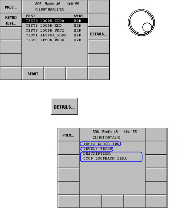
065 75$16&(,9(5 ; $ ; $
Operator’s Manual • Malfunction
– 4.20 – 6076.0822.12.01
0HQX&8,%,7'(7$,/6
This menu displays information about an IBIT result.
Starting point: Menu 805 (CU IBIT RESULTS)
+Press softkey (3) and the following display appears:
ÇSee also Menu 820 (CU ERROR LIST) and Menu 821 (CU ERROR DETAILS).
+Select message.
softkey DETAILS...
Message
Explanation of
message
Status:
Warning or Error
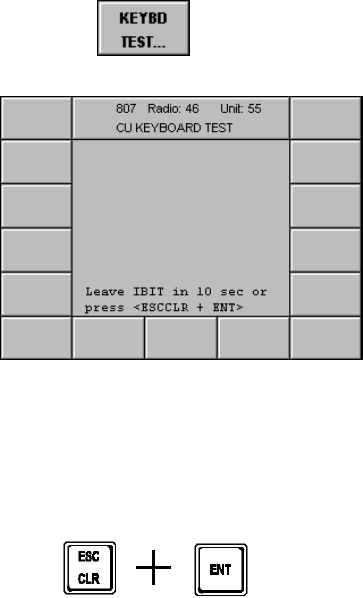
065 75$16&(,9(5 ; $ ; $
Operator’s Manual • Malfunction
6076.0822.12.01 – 4.21 –
0HQX&8.(<%2$5'7(67
In the Keyboard Test the keyboard is checked for proper functioning. For this test the operator
should press all keys and softkeys one after the other. The display shows which key has just
been pressed. The keyboard test can be stopped any time by pressing keys ESC/CLR and
ENT simultaneously.
When triggering the IBIT in Menu 805 the keyboard test is started automatically.
Starting point: Menu 805 (CU IBIT RESULTS)
+Press softkey (14) and the following display appears:
softkey KEYBD TEST...
After ten seconds the display returns to Menu 805.
o
r:
+Press keys ESC/CLR plus ENT at the same time.
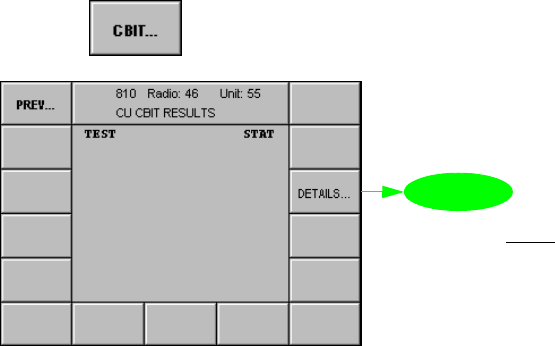
065 75$16&(,9(5 ; $ ; $
Operator’s Manual • Malfunction
– 4.22 – 6076.0822.12.01
0HQX&8&%,75(68/76
In this menu the results for the Control Unit CBIT (Continuous Built-In Test) are displayed.
Starting point: Menu 800 (CU MAINTENANCE)
+Press softkey (3) and the following display appears:
softkey CBIT...
1RWH
6RIWNH\'(7$,/6LVRQO\
HQDEOHGZLWKVWDWXV(55
0HQX
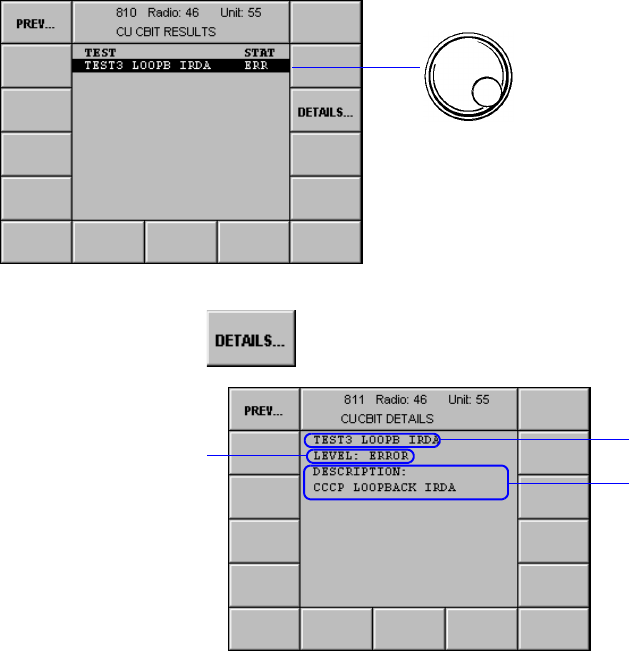
065 75$16&(,9(5 ; $ ; $
Operator’s Manual • Malfunction
6076.0822.12.01 – 4.23 –
0HQX&8&%,7'(7$,/6
This menu displays information about a CBIT result.
Starting point: Menu 810 (CU CBIT RESULTS)
+Press softkey (3) and the following display appears:
ÇSee also Menu 820 (CU ERROR LIST) and Menu 821 (CU ERROR DETAILS).
+Select message.
softkey DETAILS...
Message
Explanation of
message
Status:
Warning or Error

065 75$16&(,9(5 ; $ ; $
Operator’s Manual • Malfunction
– 4.24 – 6076.0822.12.01
0HQX&8(5525/,67
This menu displays all errors which have occurred in the control unit. The first list entry always
refers to the most recent error. Up to 100 errors may be listed. When the error list is full, a warn-
ing message comes up prompting the operator to clear the error list. Failure to do so will close
the error list for new entries.
Starting point: Menu 800 (CU MAINTENANCE)
+Press softkey (5)
qThe following display appears:
No. Control Action Notes
9 Press softkey
CLEAR LIST. Clears the complete error list in Menu
820.
softkey ERRORS...
0HQX
The latest error
Error code
number Error message
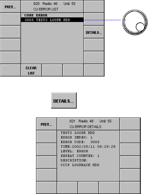
065 75$16&(,9(5 ; $ ; $
Operator’s Manual • Malfunction
6076.0822.12.01 – 4.25 –
0HQX&8(5525'(7$,/6
This menu shows the details of an error.
Starting point: Menu 820 (CU ERROR LIST)
+Press softkey (3) and the following display appears:
The details of an error selected in Menu 820 comprise the following data:
Name of error
Error index Consecutive error number in the CU error list
Error Code Error Code List
Time Time and date of error occurrence
Level Classification of failure: error or warning
Repeat Counter Number of occurrences
Description Description of failure
+Select error message.
softkey DETAILS...

065 75$16&(,9(5 ; $ ; $
Operator’s Manual • Malfunction
– 4.26 – 6076.0822.12.01
(UURU/LVW
Check the error code and proceed as indicated in the Action column (in most cases the radio
will need to be transferred to the nearest depot facility).
*) The SRAM battery is not a replaceable battery but a gold capacitor.
Code Message Level Notes Action
(CBIT message,
frequent or single event)
0002 GR General Software Error W Inform depot.
0003 GR ERR STR FULL W Error store full Inform depot.
1000 CP +28V RANGE W Control panel +28 VDC
out of range Send radio to depot.
1001 CP +2.5V RANGE W Control panel +2.5 VDC
out of range Send radio to depot.
1002 CP +3.3V RANGE W Control panel +3.3 VDC
out of range CBIT message or frequent event:
Send radio to depot.
Single event:
no action
1003 CP +5.0V RANGE W Control panel +5.0 VDC
out of range CBIT message or frequent event:
Send radio to depot.
Single event:
no action
1004 CP +12V RANGE W Control panel +12 VDC
out of range CBIT message or frequent event:
Send radio to depot.
Single event:
no action
1005 CP -12V RANGE W Control panel -12 VDC
out of range CBIT message or frequent event:
Send radio to depot.
Single event:
no action
1006 CP OVERTEMP W Control panel
overtemperature Check / correct ambient temperature
(must be below 55 °C). If this fails to
eliminate the fault, send the radio to
the depot.
1007 *) CP SRAM BATT LOW W Control panel interfaces
SRAM battery low Send radio to depot.
3000 TEST1 ALTERA_RDBK E Read back test of FPGA
failed Send radio to depot.
3001 TEST1 EPSON_RDBK E Read back test of the dis-
play controller failed Send radio to depot.
3002 TEST3 LOOPB IRDA E Loopback test of the IRDA
interface failed Send radio to depot.
3005 TEST3 LOOPB KDD E Loopback test of the KDD
serial port failed Send radio to depot.
3006 TEST3 LOOPB SMC2 E Loopback test of the serial
port SMC2 failed Send radio to depot.
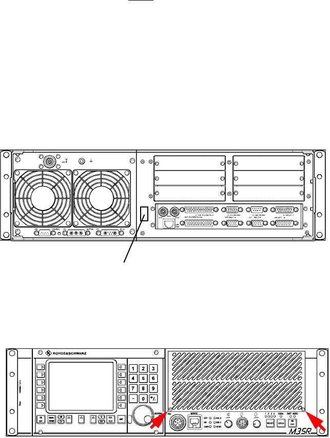
065 75$16&(,9(5 ; $ ; $
Operator’s Manual • Maintenance
6076.0822.12.01 – 5.1 –
0DLQWHQDQFH
1RWH
$OOPDLQWHQDQFHLVWREHFDUULHGRXWE\TXDOLILHGSHUVRQDORQO\
6FKHGXOHG0DLQWHQDQFH
qWe recommend to readjust the oscillators (TCXO and OCXO, part of Radio Platform
HPLAT, see the relevant Service Manual) one year after the M3SR Transceiver was first
put into operation. Only this can guarantee that the specification is met.
qThe backup battery (part of Radio Platform HPLAT, see the relevant Service Manual)
need to be replaced once every three years after installation (see figure below).
qThe filter mat of the dust protection filter needs to be cleaned or replaced (ident. no.
6102.6092.00) at certain intervals. The time interval depends on the environmental con-
ditions the transceiver is operated in. To remove the filter mat proceed as follows:
1. Undo the two screws (see figure below) fixing the cover to the front panel.
2. Carefully remove the cover.
3. Remove the filter mat from the ventilating duct.
4. Clean the filter mat by using compressed air or water.
5. Re-insert the cleaned and dried filter mat into the ventilating duct.
6. Perform steps 1 and 2 in the reverse order.
Otherwise the transceiver is free from scheduled maintenance.
Label: Date of battery installation
e.g. XT 4410A

065 75$16&(,9(5 ; $ ; $
Operator’s Manual • Maintenance
– 5.2 – 6076.0822.12.01
7DNLQJ&DUH
Such measures involve cleaning and touching up slight blemishes in the varnish coat of the
transceiver. The following materials are required:
&OHDQLQJ
:HDUJRJJOHVZKHQZRUNLQJZLWKFRPSUHVVHGDLU
LQRUGHUWRDYRLGH\HLQMXULHV
&$87,21
'LUHFWFRPSUHVVHGDLUILUVWWRZDUGVJURXQGXQWLOQRPRUHFRQGHQVHGZDWHULVFRQWDLQHG
LQWKHDLUMHW
.HHSDPLQLPXPGLVWDQFHRIFPEHWZHHQFRPSUHVVHGDLUDQGWUDQVFHLYHU
1. First of all clean surfaces of the unit with compressed air.
2. Continue cleaning with a soft brush or a duster.
3. Clean heavily contaminated surfaces, especially grease stains, with a soft, lint-free cloth
moistened with suds.
5HWRXFKLQJWKH3DLQW:RUN
Touch up the paint work of the M3SR Transceiver as follows:
1. Remove any loose paint particles from the area to be retouched.
2. Clean area to be retouched with a soft, lint-free cloth soaked in suds or similar.
3. Wait for the suds to dry out.
4. Retouch with paint carefully and allow plenty of time to dry out.
5. Once the first coat is completely dry, apply a second coat and again allow it to dry. The
repair is thus completed.
,WHP'HVFULSWLRQ
1 Soft brush
2Duster
3 Cleaning compound, e.g.
suds, household detergent
4 Varnish
Front panel:
RAL 7947 telegrey
Chassis:
KB90 grey
:$51,1*

065 75$16&(,9(5 ; $ ; $
Operator’s Manual • Technical Information
6076.0822.12.01 – A1.1 –
$ 7HFKQLFDO ,QIRUPDWLRQ
1RWH
)RUXVHRIWKH065 7UDQVFHLYHUUHDGLQJWKLVDSSHQGL[LVQRWHVVHQWLDO7KLVDSSHQGL[SUR
YLGHVLQIRUPDWLRQIRUDQ\RQHLQWHUHVWHGLQWKHWHFKQLFDOIDFWV
DQGILJXUHVRI; $RU; $
The technical information covers the following:
qExternal Interfaces
qConnection of Peripheral Equipment
qDefault Settings
qInventory Structure
qTechnical Data for M3SR Transceiver
qRemote Control
qDownload

065 75$16&(,9(5 ; $ ; $
Operator’s Manual • Technical Information
– A1.2 – 6076.0822.12.01
$ ([WHUQDO,QWHUIDFHV
(see Figs. A1.1 to A1.3)
More detailed information is provided by the interface description, available on demand from
Rohde & Schwarz at extra charge (order no.: 6102.4002.01SB).
* or ~ = inverted signal
$ 6HUYLFH),//&RQQHFWRU;RQO\; $
1RWH
)RUIXWXUHXVH
$ ),//&RQQHFWRU;
1RWH
1RWXVHG
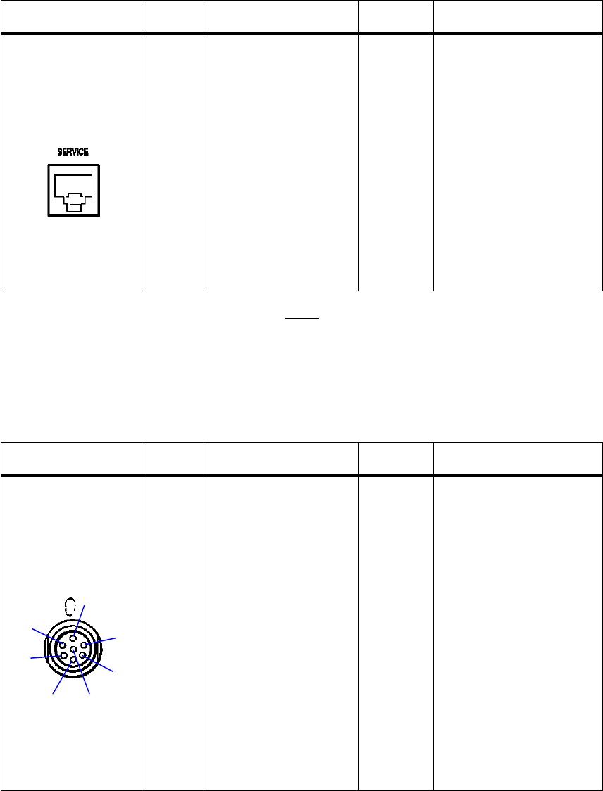
065 75$16&(,9(5 ; $ ; $
Operator’s Manual • Technical Information
6076.0822.12.01 – A1.3 –
$ /$16(59,&(&RQQHFWRU;
1RWH
;LVDQ0',;FURVVRYHUFRQQHFWRU
$ +HDGVHW&RQQHFWRU;
&RQQHFWRU &RQWDFW 6LJQDO 'LUHFWLRQ 5HPDUNV
Recessed socket,
8-way
;
(FT 4052.5738)
Mating Connector:
8-way cable plug
(FT 6083.5984)
1
2
3
4
5
6
7
8
PL_ETH_RX+
PL_ETH_RX-
PL_ETH_TX+
PL_ETH_TX-
input
input
output
output
acc. to 10BaseT
acc. to 10BaseT
acc. to 10BaseT
not connected
not connected
acc. to 10BaseT
not connected
not connected
&RQQHFWRU &RQWDFW 6LJQDO 'LUHFWLRQ 5HPDUNV
Recessed socket,
7-way
;
(FO 586.7855)
Mating Connector:
7-way cable plug
(FO 0586.8239)
Shrink-on part
(FO 0586.8245)
A
B
C
D
E
F
G
Headphones
Headphones (-)
Microphone 0.5 mV
Microphone 0.5 mV (-)
Microphone 150 mV
*PTT
GND
output
input
input
input
return to GND
return to GND
for microphone 150 mV
and *PTT
$
%
&
*'
(
)
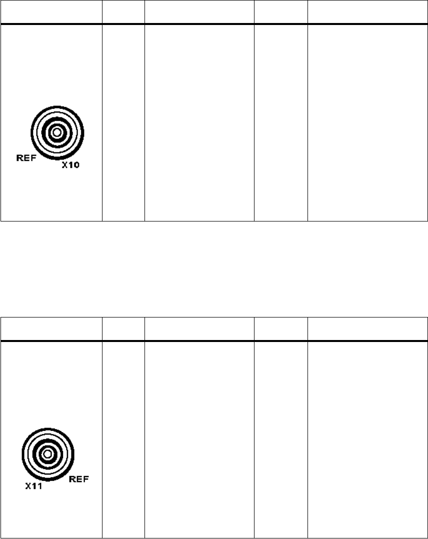
065 75$16&(,9(5 ; $ ; $
Operator’s Manual • Technical Information
– A1.4 – 6076.0822.12.01
$5HIHUHQFH)UHTXHQF\,QSXW&RQQHFWRU;
$ 5HIHUHQFH)UHTXHQF\2XWSXW&RQQHFWRU;
&RQQHFWRU &RQWDFW 6LJQDO 'LUHFWLRQ 5HPDUNV
Recessed socket,
type BNC
;
(FJ 0048.6796)
Mating Connector:
Cable plug system BNC
(FJ 0272.5930)
1
2
F_REF_IN
GND
input
&RQQHFWRU &RQWDFW 6LJQDO 'LUHFWLRQ 5HPDUNV
Recessed socket,
type BNC
;
(FJ 0048.6796)
Mating Connector:
Cable plug system BNC
(FJ 0272.5930)
1
2
F_REF_OUT
GND
output
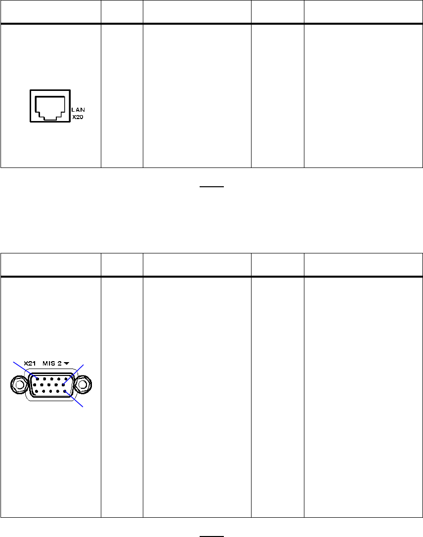
065 75$16&(,9(5 ; $ ; $
Operator’s Manual • Technical Information
6076.0822.12.01 – A1.5 –
$/$1&RQQHFWRU;
1RWH
;LVDQ0',FRQQHFWRU
$0LVFHOODQHRXV&RQQHFWRU;
1RWH
8VHU,2IRUFXVWRPHUVSHFLILFVROXWLRQV1RWVXSSRUWHGE\VRIWZDUHIRUIXWXUHXVH5HOD\FRQ
WDFWVIRUFRQWURORIH[WHUQDO5)UHOD\V
&RQQHFWRU &RQWDFW 6LJQDO 'LUHFWLRQ 5HPDUNV
Recessed socket,
8-way
;
(FT 0048.9620)
Mating Connector:
8-way cable plug
(FT 6083.5984)
1
2
3
4
5
6
7
8
PL_ETH_TX+
PL_ETH_TX-
PL_ETH_RX+
PL_ETH_RX-
output
output
input
input
acc. to 10BaseT
acc. to 10BaseT
acc. to 10BaseT
not connected
not connected
acc. to 10BaseT
not connected
not connected
&RQQHFWRU &RQWDFW 6LJQDO 'LUHFWLRQ 5HPDUNV
Male multipoint con-
nector, subminiature,
15-way
;
(FM 6104.9018)
Mating Connector:
15-way female multipoint
connector
(FM 1003.0866)
Socket contacts
(FM 1006.7410)
Shielded case
(FM 0586.9870)
1
2
3
4
5
6
7
8
9
10
11
12
13
14
15
RELAY_1
RELAY_2
RELAY_3
RELAY_4
USER_I/O_0
USER_I/O_1
USER_I/O_2
GND
USER_I/O_3
USER_I/O_4
USER_I/O_5
USER_I/O_6
USER_I/O_7
GND
USER_I/O_8
output
output
output
output
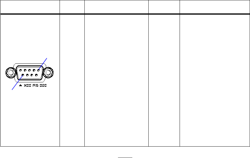
065 75$16&(,9(5 ; $ ; $
Operator’s Manual • Technical Information
– A1.6 – 6076.0822.12.01
$56&RQQHFWRU;
1RWH
1RWXVHGLQWKLVDSSOLFDWLRQ
,QWHUIDFHIRUXVHUGDWDHJWRFRQQHFWD'7(GDWDWHUPLQDOHTXLSPHQW
&RQQHFWRU &RQWDFW 6LJQDO 'LUHFWLRQ 5HPDUNV
Female multipoint
connector, 9-way
;
(FM 6104.9018)
Mating Connector:
9-way male multipoint
connector
(FM 0048.3368)
Pin contacts
(FM 0520.6344)
Shielded case
(FM 0586.9870)
1
2
3
4
5
6
7
8
9
RS 232_DCD
RS 232_RXD
RS 232_TXD
RS 232_DTR
GND
RS 232_DSR
RS 232_RTS
RS 232_CTS
RS 232_RI
output
output
input
input
output
input
output
output
data carrier detect
receive data
transmit data
data terminal ready
data set ready
ready to send
clear to send
ring indicator
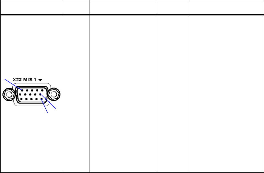
065 75$16&(,9(5 ; $ ; $
Operator’s Manual • Technical Information
6076.0822.12.01 – A1.7 –
$ 0LVFHOODQHRXV&RQQHFWRU;
*) Used in conjunction with EPM radio modes (e.g. SECOS). Not used in this application.
&RQQHFWRU &RQWDFW 6LJQDO 'LUHFWLRQ 5HPDUNV
Male multipoint con-
nector, subminiature,
15-way
;
(FM 6104.8986)
Mating Connector:
15-way female multipoint
connector
(FM 1003.0866)
Socket contacts
(FM 1006.7410)
Shielded case
(FM 0586.9870)
1
2
3
4
5
6
7
8
9
10
11
12
13
14
15
TOD_A
TOD_B
TOD
CONFIGURATION
NOGO
~ZEROIZE
~INHIBIT_TX
~INHIBIT_RX
GND
~SOK_1
~Bl_1
~SOK_2
~Bl_2
~NE_2
GND
~NE_1
bidirec.
bidirec.
output
output
input
input
input
bidirec.
bidirec.
output
output
output
bidirec.
time of day *)
time of day *)
reference voltage *)
synchronization ok *)
break-in *)
synchronization ok *)
break-in *)
net entry *)
net entry *)
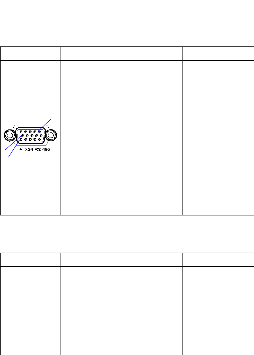
065 75$16&(,9(5 ; $ ; $
Operator’s Manual • Technical Information
– A1.8 – 6076.0822.12.01
$ 56 &RQQHFWRU;
1RWH
7KHUHPRWHFRQWUROSRUWFDQEHFRQILJXUHGLQ0HQX5$',2&21752/3257
HJWRVHULDOSRUWVWDQGDUG7KLVUHVXOWVLQWKHIROORZLQJFRQWDFWDVVLJQPHQWV
$ 5656
$ 56
&RQQHFWRU &RQWDFW 6LJQDO 'LUHFWLRQ 5HPDUNV
Female multipoint
connector, subminia-
ture, 15-way
;
(FM 6104.8986)
Mating Connector:
15-way male multipoint
connector
(FM 1006.4491)
Pin contacts
(FM 1006.4504)
Shielded case
(FM 0586.9870)
1
2
3
4
5
6
7
8
9
10
11
12
13
14
15
GND
RS485_B_A
RS485_S_A
RS485_I_A
RS485_R_A
RS485_C_A
RS485_T_A
GND
RS485_5V
RS485_B_B
RS485_S_B
RS485_I_B
RS485_R_B
RS 485_C_B
RS485_T_B
input
bidirec.
input
input
output
output
output
input
bidirec.
input
input
output
output
signal ground
clear to send
clock
data set ready
receive data
request to send
transmit data
protective ground con-
nected to chassis ground
clear to send
clock
data set ready
receive data
request to send
transmit data
&RQQHFWRU &RQWDFW 6LJQDO 'LUHFWLRQ 5HPDUNV
see appendix
A1.1.11.1
1
2
3 to 4
5
6
7
8
9 to 15
GND
CTS
RxD
RTS
TxD
GND
input
input
output
output
signal ground
clear to send
not used
receive data
request to send
transmit data
protective ground con-
nected to chassis ground
not used
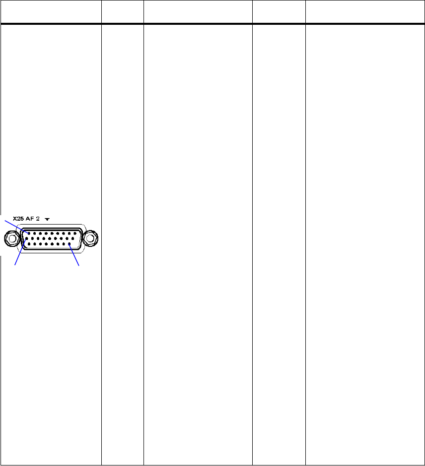
065 75$16&(,9(5 ; $ ; $
Operator’s Manual • Technical Information
6076.0822.12.01 – A1.9 –
$ $),QWHUIDFH&RQQHFWRU;
*) for future use
&RQQHFWRU &RQWDFW 6LJQDO 'LUHFWLRQ 5HPDUNV
Male multipoint con-
nector, subminiature,
26-way
;
(FM 6102.5650)
Mating Connector:
26-way female multipoint
connector
(FM 1006.7403)
Socket contacts
(FM 1006.7410)
Shielded case
(FM 0586.9564)
1
2
3
4
5
6
7
8
9
10
11
12
13
14
15
16
17
18
19
20
21
22
23 to 24
25
26
AF_TX2_NB_A
AF_TX2_NB_B
AF_RX2_NB_A
AF_RX2_NB_B
AGND
AF_TX2_WB_A
AF_TX2_WB_B
AF_RX2_WB_A
AF_RX2_WB_B
~PTT_LINE_2
AGC_RX2_1
AGC_RX2_2
SQ_MAIN_2
GND
USER_DEF_1
USER_DEF_2
PTT_2
SQ_GUARD_2
~CARRIER
~LINK11
+5V
USER_DEF_3
USER_DEF_4
input
input
output
output
input
input
output
output
input
output
output
output
bidirec.
bidirec.
input
output
output
output
output
bidirec.
bidirec.
narrowband
galvanic decoupling
narrowband
galvanic decoupling
narrowband
galvanic decoupling
narrowband
galvanic decoupling
analog ground
wideband
wideband
wideband
wideband
for second receiver *)
for second receiver *)
for second receiver *)
reserved
customer specific *)
customer specific *)
for second receiver *)
reserved
customer specific *)
customer specific *)

065 75$16&(,9(5 ; $ ; $
Operator’s Manual • Technical Information
– A1.10 – 6076.0822.12.01
$ $),QWHUIDFH&RQQHFWRU;
&RQQHFWRU &RQWDFW 6LJQDO 'LUHFWLRQ 5HPDUNV
Female multipoint
connector, subminia-
ture, 26-way
;
(FM 6102.5650)
Mating Connector:
26-way male multipoint
connector
(FM 6104.9530)
Pin contacts
(FM 1006.4504)
Shielded case
(FM 0586.9564)
1
2
3
4
5
6
7
8
9
10
11
12
13
14 to 15
16
17
18
19
20
21
22
23
24
25
26
AF_TX1_NB_A
AF_TX1_NB_B
AF_RX1_NB_A
AF_RX1_NB_B
AGND
AF_TX1_WB_A
AF_TX1_WB_B
AF_RX1_WB_A
AF_RX1_WB_B
~PTT_LINE_1
AGC_RX1_1
AGC_RX1_2
SQ_MAIN_1
GND
BB/~DP
~DPTT
PTT_1
SQ_GUARD_1
~CARRIER
+28 V_SW
+28 V_SW
ZEROIZE
PT/CT
CGC
input
input
output
output
input
input
output
output
input
output
output
output
output
output
input
output
output
output
output
output
output
input
narrowband
galvanic decoupling
narrowband
galvanic decoupling
narrowband
galvanic decoupling
narrowband
galvanic decoupling
analog ground
wideband
wideband
wideband
wideband
baseband / diphase
delayed
reserved
switched
switched
plain text / cipher text
cipher ground control
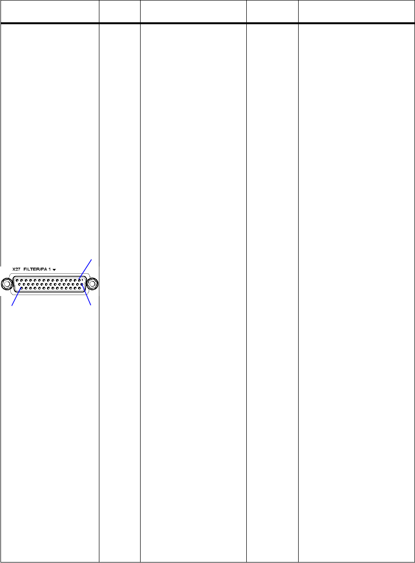
065 75$16&(,9(5 ; $ ; $
Operator’s Manual • Technical Information
6076.0822.12.01 – A1.11 –
$ )LOWHU3RZHU$PSOLILHU&RQQHFWRU;
&RQQHFWRU &RQWDFW 6LJQDO 'LUHFWLRQ 5HPDUNV
Female multipoint
connector, subminia-
ture, 44-way
;
(FM 6104.9001)
Mating Connector:
44-way male multipoint
connector
(FM 6104.9547)
Pin contacts
(FM 1006.4504)
Shielded case
(FM 0627.1826)
1
2
3
4
5
6
7
8
9
10
11
12
13
14
15
16
17
18
19
20
21
22
23
24
25
26
27
28
29
30
31
32
33
34
35
36
37
38
39
40
41
42
43
44
28V_SW
GND
~BLK
~TX_INHIBIT0
~CARRIER
~FM
~TX_RX
TEST1
VHF
100KHZ
1MHZ
800KHZ
8MHZ
40MHZ
GND
28V_SW
GND
~3DB
~ENABLE0
~VSWR
~PTT
~TX_INHIBIT1
~CARRIER
~FM
25KHZ
200KHZ
2MHZ
10MHZ
100MHZ
80MHZ
28V_SW
GND
UHF
~TX_RX
TEST0
~ENABLE1
~VSWR
~PTT
GND
50KHZ
400KHZ
4MHZ
20MHZ
200MHZ0
output
output
input
input
output
output
input
output
output
output
output
output
output
output
output
input
input
output
input
input
output
output
output
output
output
output
output
output
output
output
input
input
input
output
output
output
output
output
output
switched
blanking
switched
attenuation
switched
used as ’device select’
for certain filter types
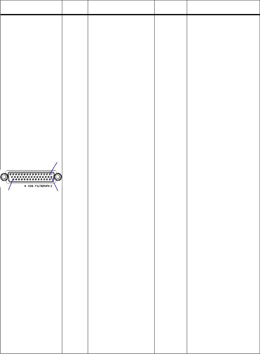
065 75$16&(,9(5 ; $ ; $
Operator’s Manual • Technical Information
– A1.12 – 6076.0822.12.01
$ )LOWHU3RZHU$PSOLILHU&RQQHFWRU;
&RQQHFWRU &RQWDFW 6LJQDO 'LUHFWLRQ 5HPDUNV
Female multipoint
connector, subminia-
ture, 44-way
;
(FM 6104.9001)
Mating Connector:
44-way male multipoint
connector
(FM 6104.9547)
Pin contacts
(FM 1006.4504)
Shielded case
(FM 0627.1826)
1
2
3
4
5
6
7
8
9
10
11
12
13
14
15
16
17
18
19
20
21
22
23
24
25
26
27
28
29
30
31
32
33
34
35
36
37
38
39
40
41
42
43
44
28V_SW
GND
~BLK
~TX_INHIBIT2
~CARRIER
~FM
~TX_RX
TEST1
VHF
100KHZ
1MHZ
800KHZ
8MHZ
40MHZ
GND
28V_SW
GND
~3DB
~ENABLE0
~VSWR
~PTT
~TX_INHIBIT3
~CARRIER
~FM
25KHZ
200KHZ
2MHZ
10MHZ
100MHZ
80MHZ
28V_SW
GND
UHF
~TX_RX
TEST0
~ENABLE1
~VSWR
~PTT
GND
50KHZ
400KHZ
4MHZ
20MHZ
200MHZ1
output
output
input
input
output
output
input
output
output
output
output
output
output
output
output
input
input
output
input
input
output
output
output
output
output
output
output
output
output
output
input
input
input
output
output
output
output
output
output
switched
blanking
switched
attenuation
switched
used as ’device select’
for certain filter types
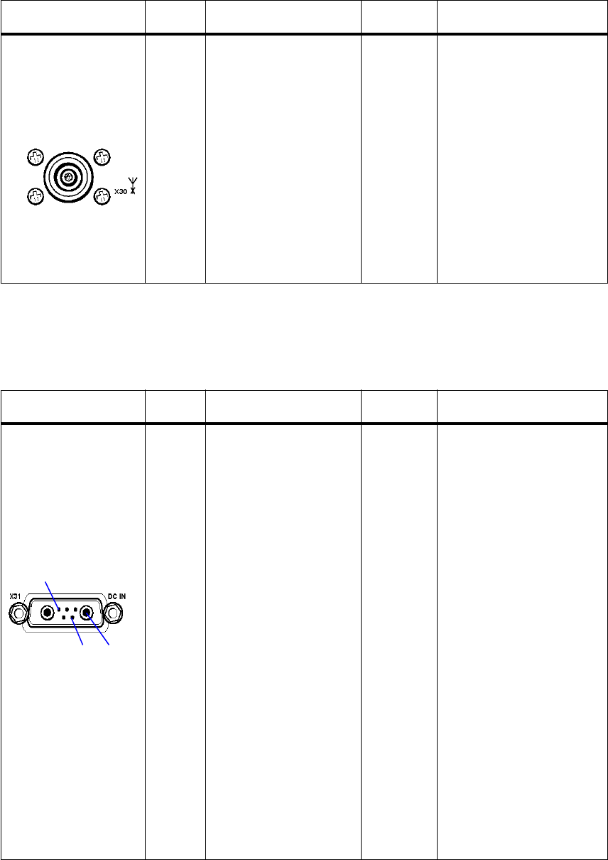
065 75$16&(,9(5 ; $ ; $
Operator’s Manual • Technical Information
6076.0822.12.01 – A1.13 –
$ $QWHQQD&RQQHFWRU;
$'&,1&RQQHFWRU;
&RQQHFWRU &RQWDFW 6LJQDO 'LUHFWLRQ 5HPDUNV
Recessed socket,
N-type
;
(FJ 6104.9353)
Mating Connector:
Cable plug system N
(FJ 0087.8850)
1
2
Antenna
GND
RF Rx input / Tx output
&RQQHFWRU &RQWDFW 6LJQDO 'LUHFWLRQ 5HPDUNV
Multipoint connector
7-way: 2 high-current
(40 A) pins + 5 auxil-
iary pins
;
(FM 6105.0337)
Mating Connector:
5-way female
multipoint connector
(FM 0066.0173)
Socket contacts
(FM 0520.6338)
High-current socket con-
tacts
(FP 0531.9233)
Shielded case
A1
A2
1
2
3
4
5
MAIN
GND
PFAIL
PTEMP
PRET
SPARE
SPARE
input
input
input
input
28 VDC nominal
100 Ω to GND
$
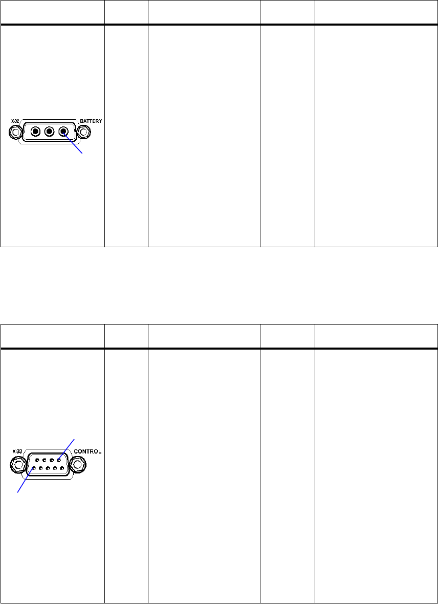
065 75$16&(,9(5 ; $ ; $
Operator’s Manual • Technical Information
– A1.14 – 6076.0822.12.01
$ %DWWHU\&RQQHFWRU;
$([WHUQDO6XSSO\&RQQHFWRU;
&RQQHFWRU &RQWDFW 6LJQDO 'LUHFWLRQ 5HPDUNV
Multipoint connector
3-way: 2 high-current
(40 A) pins
;
(FM 0070.0780)
Mating Connector:
3-way female multipoint
connector
(FM 0070.0800)
High-current contacts
(FP 0531.9233)
Shielded case
(FM 0586.9564)
A1
A2
A3
GND
SPARE
BATTERY input 19 to 31 VDC
&RQQHFWRU &RQWDFW 6LJQDO 'LUHFWLRQ 5HPDUNV
Female multipoint
connector, 9-way
;
(FM 0243.1346)
Mating Connector:
9-way multipoint
connector
(FM 0048.3368)
Pin contacts
(FM 0520.6344)
Shielded case
(FM 0586.9870)
1
2
3
4
5
6
7
8
9
28V_EXT
GND
ON
GND
28V_EXT_SW
28V_EXT
OFF
28V_EXT_SW
28V_EXT_SW
output
input
output
output
input
output
output
switched
switched
switched
$
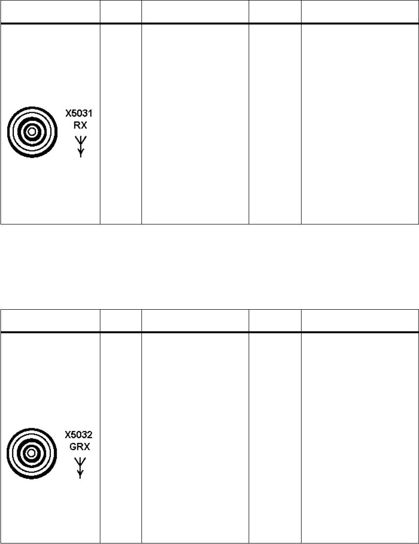
065 75$16&(,9(5 ; $ ; $
Operator’s Manual • Technical Information
6076.0822.12.01 – A1.15 –
$ 5[$QWHQQD&RQQHFWRU;3DUWRI$QWHQQD,QWHUIDFH*,
$ *5[$QWHQQD&RQQHFWRU;3DUWRI$QWHQQD,QWHUIDFH
*,0RG
&RQQHFWRU &RQWDFW 6LJQDO 'LUHFWLRQ 5HPDUNV
Recessed socket,
type BNC
;
(part of W2:
DV 6103.4864)
Mating Connector:
Cable plug system BNC
(FJ 0272.5930)
1
2
Antenna Rx
GND
input
&RQQHFWRU &RQWDFW 6LJQDO 'LUHFWLRQ 5HPDUNV
Recessed socket,
type BNC
;
(part of W1:
DV 6103.4858)
Mating Connector:
Cable plug system BNC
(FJ 0272.5930)
1
2
Antenna GRx
GND
input
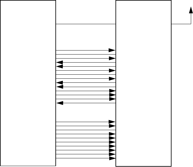
065 75$16&(,9(5 ; $
Operator’s Manual • Technical Information
– A1.16 – 6076.0822.12.02
$ &RQQHFWLRQRI3HULSKHUDO(TXLSPHQW
$ 8+)3RZHU$PSOLILHU9'/
When frequencies outside the frequency range of 225 to 400 MHz or communication mode
LINK 11, UHF Power Amplifier VD 480L will be bypassed.
The following CBIT messages relating to UHF Amplifier VD 480L may occur:
q601: IF CBIT OF EXT AMP
q602: IF VSWR OF EXT AMP
Make sure that in UHF Power Amplifier VD 480L the jumpers for connector X400 are set as
follows (see also User Manual 6045.5822.12), otherwise an error message may come up:
X400.1 and .2: jumper (voltage error)
X400.3 and .4: no jumper (no input power monitoring)
X400.5 and .6: jumper (VSWR error)
When selecting the power level, bear in mind that VD 480L can be driven with max. 25 W.
VD 480L
.13
.14
.15
.27
.28
.29
.30
.42
.43
.44
M3SR Transceiver
8MHZ
40MHZ
GND
2MHZ
10MHZ
100MHZ
80MHZ
4MHZ
20MHZ
200MHZ
X27
.1
.2
.3
.4
.5
.6
.17
.18
.19
.20
.21
.33
.34
.35
28V_SW
GND
~BLK
~TX_INHIBIT0
~CARRIER
~FM
GND
~3DB
~ENABLE0
~VSWR
~PTT
UHF
~TX/RX
TEST0
X30 X107 X108
to Antenna
X105
.25
.2
.24
.22
.19
.4
.15
.12
.10
.7
.5
.11
.9
.18
X106
.6
.14
.10
.4
.12
.7
.15
.5
.13
.8
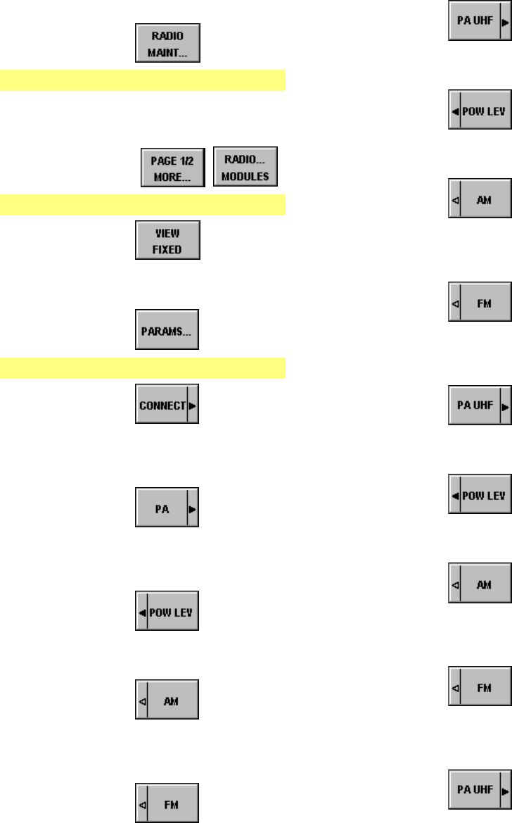
065 75$16&(,9(5 ; $ ; $
Operator’s Manual • Technical Information
6076.0822.12.01 – A1.17 –
Starting point: Menu 040 (MAIN)
1. Press softkey
Menu 400 (RADIO MAINTENANCE)
2. ENTER maintenance PIN by using
the numerical keypad, then press
ENTER.
3. Press softkeys
Menu 510 (RADIO MODULES)
4. Press softkey
5. Select module VU POWER
AMPLIFIER by using the tunig knob.
6. Press softkey
Menu 516 (VU TX PARAMETERS)
7. Press softkey
8. Select UHF Power Amplifier VD 480L
by using the tuning knob, then press
ENTER.
9. Press softkey
10. Select UHF Power Amplifier VD 480L
by using the tuning knob, then press
ENTER.
11. Press softkey
12. Select power level LOW by using the
tuning knob, then press ENTER.
13. Press softkey
14. Enter a new power level, e.g. 1 W, by
using the numerical keypad, then
press ENTER.
15. Press softkey
16. Enter a new power level, e.g. 5 W, by
using the numerical keypad, then
press ENTER.
17. Press softkey to e.g.
deactivate the power level setting
(LOW).
18. Press softkey
19. Select power level MED by using the
tuning knob, then press ENTER.
20. Press softkey
21. Enter a new power level, e.g. 2 W, by
using the numerical keypad, then
press ENTER.
22. Press softkey
23. Enter a new power level, e.g. 10 W,
by using the numerical keypad, then
press ENTER.
24. Press softkey to e.g.
deactivate the power level setting
(MED).
25. Press softkey
26. Select power level HIGH by using the
tuning knob, then press ENTER.
27. Press softkey
28. Enter a new power level, e.g. 12 W,
by using the numerical keypad, then
press ENTER
29. Press softkey
30. Enter a new power level, e.g. 15 W,
by using the numerical keypad, then
press ENTER.
31. Press softkey to e.g.
activate the power level setting
(HIGH).
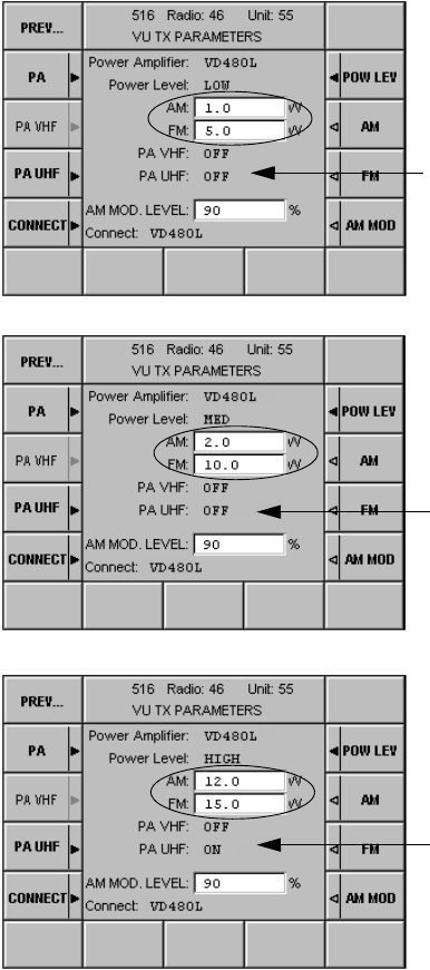
065 75$16&(,9(5 ; $ ; $
Operator’s Manual • Technical Information
– A1.18 – 6076.0822.12.01
Since the power amplifier is deactivated (PA UHF
= OFF), the default values are used for PTT in-
stead of the values configured for AM or FM.
Default values:
AM = 3 W
FM = 5 W
Since the power amplifier is deactivated (PA UHF
= OFF), the default values are used for PTT in-
stead of the values configured for AM or FM.
Default values:
AM = 10 W
FM = 10 W
Since the power amplifier is activated (PA UHF =
ON), the configured values are used for PTT in-
stead of the default values.
Configured values:
AM = 12 W → 12 W x gain of VD 480L
FM = 15 W → 15 W x gain of VD 480L
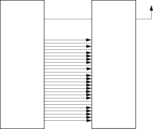
065 75$16&(,9(5 ; $ ; $
Operator’s Manual • Technical Information
6076.0822.12.01 – A1.19 –
$ 8+)$JLOH)LOWHU)'
The UHF Agile Filter FD 430 can be used in all communication modes.
Only frequencies from the frequency range 225 to 400 MHz are permitted to be used.
Softkey PA UHF has no function, because FD 430 is active always and cannot be bypassed.
When selecting the power level, bear in mind that UHF Agile Filter FD 430 can be driven with
max. 10 W (AM) or 15 W (FM).
FD 430
M3SR Transceiver
X27
.1
.2
.6
.10
.11
.12
.13
.14
.15
.16
.17
.21
.25
.26
.27
.28
.29
.30
.31
.32
.39
.40
.41
.42
.43
.44
28V_SW
GND
~FM
100KHZ
1MHZ
800KHZ
8MHZ
40MHZ
GND
28V_SW
GND
~PTT
25KHZ
200KHZ
2MHZ
10MHZ
100MHZ
80MHZ
28V_SW
GND
GND
50KHZ
400KHZ
4MHZ
20MHZ
200MHZ
X30 X5 X2
to Antenna
X1
.1
.3
.29
.30
.13
.33
.16
.36
.4
.2
.5
.26
.11
.31
.14
.34
.17
.37
.20
.19
.25
.12
.32
.15
.35
.18
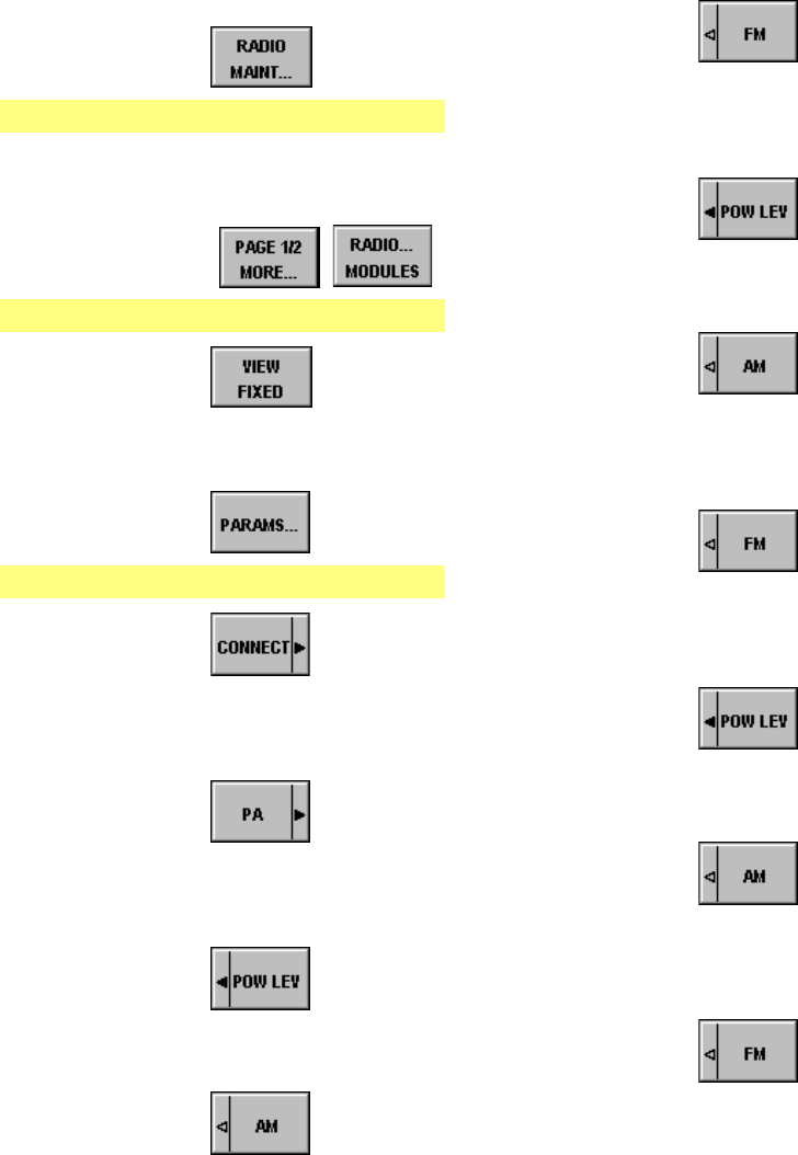
065 75$16&(,9(5 ; $ ; $
Operator’s Manual • Technical Information
– A1.20 – 6076.0822.12.01
Starting point: Menu 040 (MAIN)
1. Press softkey
Menu 400 (RADIO MAINTENANCE)
2. ENTER maintenance PIN by using
the numerical keypad, then press
ENTER.
3. Press softkeys
Menu 510 (RADIO MODULES)
4. Press softkey
5. Select module VU POWER
AMPLIFIER by using the tuning knob.
6. Press softkey
Menu 516 (VU TX PARAMETERS)
7. Press softkey
8. Select UHF Agile Filter FD 430 by us-
ing the tuning knob, then press
ENTER.
9. Press softkey
10. Select UHF Agile Filter FD 430 by us-
ing the tuning knob, then press
ENTER.
11. Press softkey
12. Select power level LOW by using the
tuning knob, then press ENTER.
13. Press softkey
14. Enter a new power level by using the
numerical keypad, then press
ENTER.
15. Press softkey
16. Enter a new power level by using the
numerical keypad, then press
ENTER.
17. Press softkey
18. Select power level MED by using the
tuning knob, then press ENTER.
19. Press softkey
20. Enter a new power level by using the
numerical keypad, then press
ENTER.
21. Press softkey
22. Enter a new power level by using the
numerical keypad, then press
ENTER.
23. Press softkey
24. Select power level HIGH by using the
tuning knob, then press ENTER.
25. Press softkey
26. Enter a new power level by using the
numerical keypad, then press
ENTER.
27. Press softkey
28. Enter a new power level by using the
numerical keypad, then press EN-
TER.
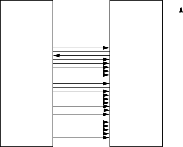
065 75$16&(,9(5 ; $ ; $
Operator’s Manual • Technical Information
6076.0822.12.01 – A1.21 –
$ 8+)$XWRPDWLF)LOWHU)'
UHF Filter FD 221 can be used in all communication modes.
Only frequencies from the frequency range between 225 and 400 MHz are permitted to be
used.
Filter tuning is monitored by signal ~Tx_INHIBIT0 (contact X27.4). As long as filter tuning is in
progress, the transmitter is disabled. If tuning fails to be completed within approximately 20 s,
the message " 603: EXT PA TUNING X27" comes up.
No setup procedures are required in the M3SR Transceiver.
FD 221
M3SR Transceiver
X27
.1
.2
.4
.10
.11
.12
.13
.14
.15
.16
.17
.25
.26
.27
.28
.29
.30
.31
.32
.40
.41
.42
.43
.44
28V_SW
GND
~TX_INHIBIT0
100KHZ
1MHZ
800KHZ
8MHZ
40MHZ
GND
28V_SW
GND
25KHZ
200KHZ
2MHZ
10MHZ
100MHZ
80MHZ
28V_SW
GND
50KHZ
400KHZ
4MHZ
20MHZ
200MHZ
X30 X10 X20
to Antenna
X1
.31
.34
.18
.3
.7
.6
.10
.13
.35
.32
.36
.1
.4
.8
.11
.15
.14
.33
.19
.2
.5
.9
.12
.16

065 75$16&(,9(5 ; $ ; $
Operator’s Manual • Technical Information
– A1.22 – 6076.0822.12.01
$ 'HIDXOW6HWWLQJV
There are two different scenarios for default settings to become active:
qThe radio is powered up for the first time.
qThe radio is reset during operation by using softkey DEFAULT SETTINGS in Menu 400.
In this case only the maintenance parameters will be reset, all other parameters are not
affected. In the tables below, such parameters non-affected by a reset are marked by an
"N" in the last column.
Frequency 310 MHz (UHF and VHF/UHF)
Mode FIX.FRQ
Guard OFF
Power HIGH
Modulation AM
Squelch ON
Marker OFF
H-Duplex
H-Duplex RX
H-Duplex TX
OFF
310 MHz (UHF and VHF/UHF)
311 MHz (UHF and VHF/UHF)
Clipper OFF
COMM V/D UNCPH
Chan SP 25 kHz
Tx Offs OFF
AF AGC OFF
Preset No. 0
Band UHF
Radio Time
Date
00:00
01.01.70
N
N
Default Address Radio Logical 46
IP 192.168.052.046 T R
N
Radio Modules Slot 0 VU GRX, ALL
Slot 3 VU SYN, CL1
Slot 4 VU RX, CL1
Slot 17 VU TX, CL1
Slot 18 PLAT, ALL
Slot 19 AFI, CL1
Slot 20 PLAT INT, ALL
N
N
N
N
N
N
N
Operation type Manual
Remote Control RS485 (X24) 9 600, 7, 1, ODD, RS485, S400U protocol

065 75$16&(,9(5 ; $
Operator’s Manual • Technical Information
6076.0822.12.02 – A1.23 –
Module Parameters CPLAT:
RX SQ Level S/N 10 dB
Input RXTX or RX
1RWH
,QFRQMXQFWLRQZLWK$QWHQQD,QWHU
IDFH*, DQGZLWKRXW8+)
)LOWHU)' VHOHFW5;LQDOO
RWKHUFDVHV5;7;LQSXW
N
Clipper Level 90%
Sensitivity LN
Attack 10 ms
Decay 100 ms
TX AM TX Power 3, 10, 30
FM TX Power 5, 10, 45
AM MOD 90%
Voltage Protection ON
External Power Amplifier None
External Filter None
SY
(Parameters
for AFI)
TX Deviation WB 6.3 kHz
TX Deviation NB 3.5 kHz
TX Deviation L11 20 kHz
TX Deviation TRIM 0% N
Plat VCXO 2 047 N
TCXO 2 047 N
OCXO 32 767 N
Ref Out 10 MHz
EXT REF OFF
REF IN INPUT OFF
PWR SUP MAIN
CLK SRC OCXO (if unavailable: TCXO)
AFI TX ALC ON
RX LEVEL 0 dBm
TX LEVEL 0 dBm
TX ALC Attack 30 ms
TX ALC Decay 300 ms
TX ALC Level 0 dB
Marker Volume -1.5 dB
Guard Volume 0 dB
Sidetone Volume -6 dB
Split Site Simple

065 75$16&(,9(5 ; $
Operator’s Manual • Technical Information
– A1.24 – 6076.0822.12.02
Default values for Setup:
Default values for Control Unit GB 4000C
Standby not selectable
PTT Mapping PTT1 CL1
low
PTT1L Rem CL1
low
PTT2 CL1
high
PTT2L Rem CL1
low
Phantom Mapping not selectable
Audio Mapping WB1 none
NB1 to CL1
WB2 to CL1
NB2 none
Device Mapping All none, no CL assigned
SQ Polarity All low
Audio Source Source 1 = CL1
2 = Guard U/V
Marker Control Disabled
Local Mode OFF N
PINs All PINs set to 00000 N
Active Preset 1 N
Preset Count 1 N
No. of Pages 200 N
Default Address Control Unit Logical 47
IP 192.168.052.047 T C
N
Contrast 100% N
Brightness 100% N
Display Timer 60 min N
Indicators 100% N
Key Illumination 100% N
Frequency ICAO N
Date Format YYYY / MM / DD N

065 75$16&(,9(5 ; $ ; $
Operator’s Manual • Technical Information
6076.0822.12.01 – A1.25 –
$ ,QYHQWRU\6WUXFWXUH
In Menu 415 INVENTORY all components installed in the radio are listed:
In Menu 815 INVENTORY all components installed in the control unit are listed:
e.g. XT4410A (DEV) DS 4400A PACK (SWM) PLATFORM (SW)
BOOTPROG (FW)
KR 4400 BASIS (HWM) PLATFORM (HW)
FRONT PANEL B (HW)
DSP MODULE (HW)
CPLD KR 4400 (FW)
ACPCB ws EQI (FW)
DSP KR 4400 (FW)
DSP CPLD (FW)
ET 4400 REC (HWM) RECEIVER B (HW)
FLASH ET 4400 (FW)
ET 4400G REC (HWM) GUARD REC B (HW)
FLASH ET 4400G (FW)
GF 4400T SYNTH (HWM) SYNTHESIZER B (HW)
VCO BOARD (HW)
XIL GF 4400T (FW)
ALT GF 4400T (FW)
VT 4403 TRANSM (HWM) TRANSMITTER B (HW)
DRIVER AMP (HW)
POWER SUPPLY (HW)
DSP VT 4403 (FW)
DSP CPLD (FW)
FD 4430 UHF (HWM) FW XILINX (FW)
HF BOARD (HW)
DIGITAL BOARD
GB 4000C CONTR (HVM) CONTROLLER B (HW)
FRONT PANEL B (HW)
ACPCB ws EQI (FW)
CONTR GB 4000C (SW)
BOOTPR GB 4000C (FW)
065 75$16&(,9(5 ; $ ; $
Operator’s Manual • Technical Information
– A1.26 – 6076.0822.12.01
$7HFKQLFDO'DWD
See data sheet for Digital Programmable Software Radios of Series M3SR in the annex.

065 75$16&(,9(5 ; $ ; $
Operator’s Manual • Technical Information
6076.0822.12.01 – A1.27 –
$ 5HPRWH&RQWURO
For remote control of the M3SR Transceiver two different serial connections may be used:
*) The protocol and the serial port standard for the serial connection X24 can be configured
via Menu 425 (SERIAL CONTROL INTERFACE).
The following table shows the difference between the protocols:
x = supported FF = fixed frequency
6HULDO
&RQQHFWLRQ
6HULDO3RUW
6WDQGDUG3URWRFRO 1RWH
X6 / X20 LAN GB2PP Multipoint connection
(TCP IP addressing)
X24 *) RS232
RS422
GB2PP Point-to-point connection
RS232
RS422
S400U Point-to-point connection
RS485 S400U Multipoint connection
(with CSMA/CD)
68 *%33
Operation mode:
•Manual
•Preset
•Emergency
;(only FF)
;(only FF)
;(only FF)
;
;
;
Radio maintenance - ;
Preset Page setup - ;
CBIT status ;;
Error List:
•Read
•Clear
-
-
X
X
Start of IBIT - X
Session control - X

065 75$16&(,9(5 ; $
Operator’s Manual • Technical Information
– A1.28 – 6076.0822.12.02
$ 5HPRWH&RQWUROYLD56&RQQHFWRU;DQG*%333URWRFRO
The Radio Interface Unit (RIU) uses the GB2PP protocol to control the radio. When the RIU
has connected to the radio in an Advanced session, all other control units may take control of
the radio any time. For this to happen, only the session needs to be changed from Monitoring
to Advanced or Fixed. Menu 020 (COMLINE SESSION) contains an indication that the radio is
being controlled by an RIU (ADR = 999) in Advanced session.
; ;
Radio
Interface
Unit
LAN
GB2PP Protocol
Remote Control Unit
GB 4000C,
mod. 03
e.g. RS232
GB2PP Protocol
Radio interface unit controls
the M3SR Transceiver in
Advanced session.
Control unit is in Monitoring session.
Advanced / Fixed session and local
mode are possible.
Control unit is in Monitoring
session.
Advanced / Fixed session is
possible.
Radio Interface Unit is in Ad-
vanced session and controls
the radio.

065 75$16&(,9(5 ; $ ; $
Operator’s Manual • Technical Information
6076.0822.12.01 – A1.29 –
$ 5HPRWH&RQWUROYLD56&RQQHFWRU;DQG683URWRFRO
As soon as a radio address has been configured on one of the Control Units GB 406, this con-
trol unit will automatically connect to the radio in Fixed session. All other control units will only
be able to monitor. Menu 020 (COMLINE SESSION) contains an indication that the S400U pro-
tocol is being used for radio control (ADR = 400U).
LAN Hub
Customer-
specific
Device
;
;
; ;
;
;
only Monitor-
ing session
only Monitoring session or
local mode
Control Unit GB 406 controls
the M3SR Transceiver in
Fixed session
Remote Control Unit GB 406
Remote Control Un
it
GB 4000C,
mod. 03
LAN
GB2PP Protocol
RS485
S400U Protocol
DSSOLFDWLRQSURWRFRO
SUHYHQWVFROOLVLRQV
only Monitoring
session
only Fixed
session only Fixed
session

065 75$16&(,9(5 ; $
Operator’s Manual • Technical Information
– A1.30 – 6076.0822.12.02
$'RZQORDG
q6RIWZDUH'RZQORDG
A software CD is delivered together with each radio. The software CD contains the com-
plete Software Package. The Software Package itself consists of various software and
firmware items. The following table (example for fullband transceiver = XT) shows which
software and firmware items are upgradable.
In addition, the software CD contains the Update32 and Service- and Maintenance Tool
ZS 4400 (basis edition) for upgrading the software, as well as a list of known software
bugs. The software CD can be reordered any time by stating the ident. no. of the
DS4400A Pack (e.g. 6102.2068.05).
The manufacturer provides tools to download these data. The download can be per-
formed via LAN by using connectors X6 (front) and X20 (rear). The actual download tool
runs on any standard PC supporting Windows NT4™ or Windows W2k™.
For detailed information please contact the manufacturer’s representative in charge.
7\SH1DPH ,GHQW1R9HUVLRQ 8SJUDG
DEOH 5HPDUN
SWM DS4400A Pack 6102.2068.05
6102.2051.04 01.00
01.00 yes
yes with Link 11
without Link 11
SW PLATFORM 6103.6021.03
6103.6038.03 03.72
03.72 yes
yes with Link 11
without Link 11
FW BOOTPROG 6102.5621.02 12.03 no
FW CPLD KR4400 6102.5609.02 01.00 no
FW ACPCB ws EQI 6105.6412.06 01.27 yes
FW DSP KR4400 6102.5644.02 03.46 yes
FW DSP CPLD 6105.8550.02 01.02 no
FW FLASH ET4400 6102.7118.02 01.33 yes
FW FLASH ET4400G 6102.8614.02 01.03 yes
FW XIL GF4400T 6102.6611.02 04.00 yes
FW ALT GF4400T 6102.6605.02 04.00 yes
FW DSP VT4403 6102.7599.02 03.36 yes
FW DSP CPLD 6105.8550.02 01.02 no
SW CONTR GB4000C 6103.6109.02 03.72 yes only X. 4410A
FW BOOTPR GB4000C 6105.6406.02 12.03 no only X. 4410A
FW ACPCB ws EQI 6105.6412.06 01.27 yes only X. 4410A
FW FW XILINX 6103.2084.02 01.08 no FD 4430

065 75$16&(,9(5 ; $ ; $
Operator’s Manual • Technical Information
6076.0822.12.01 – A1.31 / A1.32 –
Update 32 Tool
The Update 32 Tool is contained on the software CD that is delivered with each
M3SR Transceiver. Downloading the software is done in a number of single steps.
Please follow the instructions in the Software Manual of the Update 32 Tool (ident. no.
6076.0168.42). It is also contained on the software CD. Another, more comfortable
means for upgrading is the Service and Maintenance Tool ZS 4400.
Service & Maintenance Tool ZS 4400 (ident. no. 6105.2600.02)
The Service & Maintenance Tool automatically compares the software and firmware
loaded in the M3SR Transceiver with that on the software CD. In the case that any differ-
ence is detected, the required upgrade is performed also automatically.
Please follow the instructions in the Software Manual of Service & Maintenance Tool
ZS 4400.
q/RDGLQJWKH3UHVHW3DJHVLQWRWKH5DGLR
Control Unit GB 4000C
The Preset Pages can be entered manually via the following menus:
620 (LOADED PRESET PAGES PARAMS) and
710 (EDIT PRESET PAGE (FIX.FRQ).
Service & Maintenance Tool ZS 4400 (ident. no. 6105.2600.02)
The Service & Maintenance Tool can be used to retrieve from the radio (reference de-
vice) all Preset Pages that have been edited manually, to duplicate them in a second step
into other radios.
Please follow the instructions in the Software Manual of Service & Maintenance Tool
ZS 4400.

065 75$16&(,9(5 ; $ ; $
Operator’s Manual • Technical Information
6076.0822.12.01 – A1.33 / A1.34 –
)LJ $ ([WHUQDO,QWHUIDFHVRI; $)URQW
Mating Connector:
8-way cable plug
(FT 6083.5984)
Mating Connector:
7-way cable plug
(FO 0586.8239)
Shrink-on part
(FO 0586.8245)
for future use
$
%
&
'
(
)
(X4)
(X5) (X6) (X7)
%
&
*
'
(
)
1RWH
0DWLQJFRQQHFWRUVDUHFRQWDLQHG
LQ&RQQHFWRU6HW=)
SDUWQR
not used
$

065 75$16&(,9(5 ; $ ; $
Operator’s Manual • Technical Information
6076.0822.12.01 – A1.35 / A1.36 –
)LJ $ ([WHUQDO,QWHUIDFHV5HDU
Mating Connector:
44-way male multipoint
connector
(FM 6104.9547)
Pin contacts
(FM 1006.4504)
Shielded case
(FM 0627.1826)
Mating Connector:
44-way male multipoint
connector
(FM 6104.9547)
Pin contacts
(FM 1006.4504)
Shielded case
(FM 0627.1826)
Mating Connector:
15-way female multipoint
connector
(FM 1003.0866)
Socket contacts
(FM 1006.7410)
Shielded case
(FM 0586.9870)
Mating Connector:
15-way female
multipoint connector
(FM 1003.0866)
Socket contacts
(FM 1006.7410)
Shielded case
(FM 0586.9870)
Mating Connector:
26-way female
multipoint connector
(FM 1006.7403)
Socket contacts
(FM 1006.7410)
Shielded case
(FM 0586.9564)
Mating Connector:
26-way male multipoint
connector
(FM 6104.9530)
Pin contacts
(FM 1006.4504)
Shielded case
(FM 0586.9564)
Mating Connector:
9-way male multipoint
connector
(FM 0048.3368)
Pin contacts
(FM 0520.6344)
Shielded case
(FM 0586.9870)
Mating Connector:
15-way male multipoint
connector
(FM 1006.4491)
Pin contacts
(FM 1006.4504)
Shielded case
(FM 0586.9870)
Mating Connectors:
Cable plug system BNC
(FJ 0272.5930)
Mating Connector:
5-way female multipoint
connector
(FM 0066.0173)
Socket contacts
(FM 0520.6338)
High-current socket contacts
(FP 0531.9233)
Shielded case
(FM 0586.9564)
$
$
Mating Connector:
3-way female multipoint
connector
(FM 0070.0800)
High-current contacts
(FP 0531.9233)
Shielded case
(FM 0586.9564)
Mating Connector:
9-way multipoint
connector
(FM 0048.3368)
Pin contacts
(FM 0520.6344)
Shielded case
(FM 0586.9870)
Mating Connector:
Cable plug system N
(FJ 0087.8850)
Mating Connector:
8-way cable plug
(FT 6083.5984)
1RWH
0DWLQJFRQQHFWRUVDUHFRQWDLQHG
LQ&RQQHFWRU6HW=)
SDUWQR
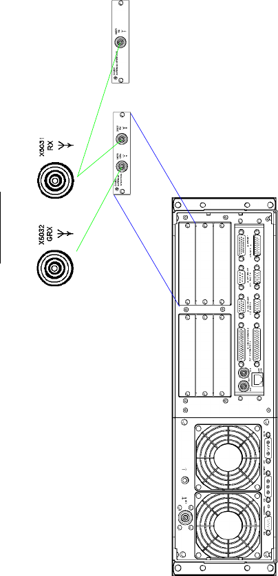
065 75$16&(,9(5 ; $ ; $
Operator’s Manual • Technical Information
6076.0822.12.01 – A1.37 / A1.38 –
)LJ $ ([WHUQDO,QWHUIDFHV5HDU0RGXOHV
Mating Connectors:
Cable plug system BNC
(FJ 0272.5930)
RU
*,0RG
*,0RG

Digital Reprogrammable Software Radios R&S M3SR
Your key to interoperability
◆Software download of new
waveforms
◆High growth potential through P3I
(preplanned product improvement)
◆Embedded hopping filter optionally
available
◆High operational flexibility while on
mission
◆Interoperability with existing radios
according to international standards
◆Easy system integration
◆Low life cycle costs

2Digital Reprogrammable Software Radios R&S M3SR
The R&S M3SR (multiband, multimode
and multirole surface radio) represents an
innovative and versatile generation of
software radios for use in the navy, civil
and military air traffic control, air defence
and stationary applications.
In addition to the R&S M3TR (multiband,
multimode and multirole tactical radio)
and R&S M3AR (multiband, multimode
and multirole airborne radio), the R&S
M3SR is the third element of a new radio
equipment generation. All three feature
functionality that can be varied by means
of software.
For the commercial user, the basic units
come standard with the waveform for air
traffic control (ATC) in line with
EN300676. The R&S M3SR can be used
both in normal ATC operation and as an
emergency backup radio.
The R&S M3SR is interoperable with
many types of existing radio equipment
and standards. For military customers,
this means seamless communication
with their own and allied troops. To com-
municate with neighbouring troops, the
radio is switched to the waveform or
communication protocol used there. This
switchover can be carried out online even
during a mission.
The operational functions and the avail-
able waveforms are determined by the
loaded application software. Additional
functions can be implemented, as
required, by downloading the appropriate
software and/or using plug-in hardware
modules.
Modular design
The R&S M3SR features highly modular
hardware and software architecture. All
R&S M3SR units are based on the uni-
form Radio Basis R&S KR4400. The versa-
tile P3I upgrade concept of the basic
version helps to avoid unnecessarily high
initial investment costs.
The R&S M3SR is available as a receiver,
transmitter or transceiver, according to
the customer's requirements.
Radio Basis R&S KR4400
The various models are set up on the
hardware and software of the Radio Basis
R&S KR4400, which forms the central and
common part of all R&S M3SR radios. The
radio basis is independent of the RF-
specific modules. Additional radio-
specific hardware and software modules
define the performance features of the
radio.
The R&S KR4400 consists of the mechan-
ical frame, the radio platform and a front
panel with audio interface, loudspeaker
and status displays. The platform is the
control center of the radio. The embedded
realtime operating system controls and
monitors all functions in the radio. A con-
trol panel (R&S GB4000C) can be inte-
grated for local control of the radios.
The main tasks of the radio basis include:
◆Monitoring and control of the
complete radio unit
◆Mechanical and electrical accommo-
dation of modules and control panel
◆Digital voice and data processing
◆Internal routing of information data
to the interfaces
◆Standard interfaces to peripherals
◆Audio interface, loading of encryp-
tion keys and display of status infor-
mation
An oven-controlled crystal oscillator
(OCXO) is integrated as standard to meet
the stringent requirements regarding
time stability.
For the configuration of the various radio
models, the radio basis is equipped with
slots for the radio modules, and a
mechanical fixture on the side to accom-
modate the transmitter module.

Digital Reprogrammable Software Radios R&S M3SR 3
Key features of the modules
The modules have the following out-
standing features:
◆Independent use of all modules
(no alignment or manual adjustment
when modules are replaced)
◆Central download of software and
firmware (no need to open the
radio unit)
◆Data exchange via radio module bus
◆Type label with bar code identification
down to PCB level (fast automated
detection and identification)
◆All modules with electromagnetic
shielding (maximum EMC/EMI
immunity)
◆All settings made via software
(reduced maintenance)
◆Fast and easy replacement of
modules (short MTTR)
Modules for radio module slots
VHF/UHF Synthesizer Module
R&S GF4400T
The synthesizer module is the core of the
high-frequency structure of the radio
unit. It covers the frequency range from
100 MHz to 512 MHz, generates the RF
signal for driving the transmitter and sup-
plies the local oscillator (LO) signal for the
receiver module. Direct digital synthesis
(DDS) technology ensures fine frequency
tuning with high accuracy and high
speed. The extremely low-noise signal
generation allows the radio to be used at
sites with stringent requirements regard-
ing large-signal immunity (collocation).
VHF/UHF Receiver Module
R&S ET4400
The Main Receiver Module R&S ET4400
can be universally used for all operational
modes in the VHF/UHF range. The use of
programmable VLSI components makes
the module extremely compact, occupy-
ing only one slot. The flexible digital
demodulator allows the processing of
complex digital waveforms.
VHF/UHF Guard Receiver
R&S ET4400G
The R&S ET4400G simultaneously moni-
tors the emergency frequencies in the
VHF (121.5 MHz) and UHF (243 MHz)
ranges and can be installed in any R&S
M3SR model, irrespective of the other
modules. The AF of the guard receiver can
either be routed to one of the audio inter-
faces or mixed with the AF of the main
receiver. The software for using a guard
receiver is supplied with the basic unit.
Electronic Protective Measures (EPM)
Processor Module R&S GP4400
The powerful EPM Processor Module R&S
GP4400 handles data processing for spe-
cial waveforms. It occupies one radio mod-
ule slot and can host EPM waveforms such
as SATURN, SECOS or HAVE QUICK I/II on
its memory devices. Its functionality is
determined by the loaded software.
Power modules
VHF/UHF Transmitter Module
R&S VT4403
The R&S VT4403 is a universal transmitter
module for all operational modes in the
frequency range 100 MHz to 512 MHz
and is mounted in the R&S KR4400. This
means that there is one transmitter for
each radio. A PIN diode switch is pro-
vided for fast and reliable switchover
between transmission and reception. Two
low-noise, temperature-controlled fans
are provided on the rear panel for heat
dissipation of the transmitter.
Main Receiver Module R&S ET4400
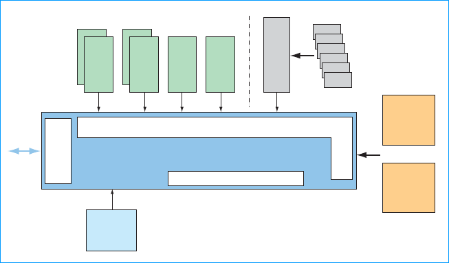
4Digital Reprogrammable Software Radios R&S M3SR
or
Radio modules
Power modules
RX
Synthesizer
EPM
processor
Radio basis
Radio module bus (RMB)
Standard I/O
Guard
receiver
incl. DC
power supply
AC/DC
power
supply
Radio control and signal processing
Local
control
panel
Backplane
Audio front panel with fill gun connector
Interface cards
TX
Block diagram of R&S M3SR
Internal AC/DC Power Supply
R&S IN4400A
The R&S IN4400A is the internal AC/DC
power supply required for receiver and
multireceiver radio types. Its submodules
are an AC/DC converter and a DC/DC con-
verter. The AC/DC converter delivers DC
from the external mains supply. The R&S
IN4400A occupies the slot assigned to
the transmitter module. The external
Universal Power Supply R&S IN4000A is
required for transceivers or transmitters.
Local control panel
A local control panel can be integrated in
the front of the Radio Basis R&S KR4400.
If a local control panel is not required, a
blank panel is fitted instead.
Comfort Control Panel (CCP)
R&S GB4000C
The ½ 19" plug-in CCP is the standard
control panel and allows easy and conve-
nient local control of the radio. All radio
functions are controlled by the R&S
GB4000C. The 5" display has softkeys and
a user-friendly, menu-guided user inter-
face. The keypad is backlighted by LEDs.
Any additional R&S M3SR units that are
connected can be controlled and moni-
tored from a local control panel.
Interfaces
In addition to the interfaces provided as
standard, interface cards can be inserted.
Six free slots are available for interface
cards. These cards may contain customer-
specific interfaces as well as other func-
tions.
Backplane R&S GH4400
The Backplane R&S GH4400 connects the
optional interface cards and the transmit-
ter module to the radio module bus. This
passive PCB does not occupy a radio
module slot. The Backplane R&S GH4400
is required for every R&S M3SR configu-
ration except receivers, which do not
need interface cards.
Antenna connector configura-
tions
The connector for a combined transmit-
ting/receiving antenna is configured as
standard. Depending on the antennas
used, various connector combinations are
offered. This means that either separate
or combined antenna connectors are
available for main receiver, guard receiver
and transmitter.
Due to the use of a universal wideband
amplifier, only one antenna connector is
required, irrespective of the frequency
range. If separate operation of the VHF
and UHF range is required for special
applications, an external diplexer (e.g.
R&S FT224) has to be used.
Remote control
A variety of standardized interfaces is
available for remote control of the radio
units. An integrated LAN (local area net-
work) hub allows easy integration into
data networks. Any number of radios can
thus be controlled from a central operator
position.
The R&S M3SR radios can be remote-con-
trolled via external remote control units,
other R&S M3SR units with integrated
control panel, Rohde&Schwarz remote
control systems or customer-specific
solutions.

Digital Reprogrammable Software Radios R&S M3SR 5
Built-in test (BIT) concept
An efficient BIT concept allows identifica-
tion and location of functional failures
down to module level. All failures
detected during the test can be indicated
locally and remotely.
◆Power-up BIT (PBIT)
Automatic test after power-up of the
unit
◆Continuous BIT (CBIT)
Automatic start after successful PBIT
and continuous and automatic moni-
toring of all modules including radio
basis during operation
◆Initiated BIT (IBIT)
Interactive test in non-operating
status to support maintenance of the
radio units; can be triggered locally or
remotely; test and analysis of the
signal path in the radio with the aid of
test signals without disconnecting the
antenna connector (test signal gener-
ator already built in; simplified diag-
nostics possible without opening the
unit)
Radio failure archive
All failures detected and error messages
are stored in the radio failure archive. The
archive can be read locally on the CCP
and remotely. Each entry also contains a
description in plain text.
Inventory report
The software and hardware states of the
radio system are entered in full detail into
the inventory report. The report allows a
fast overview of the total configuration
status without having to open the unit.
Power supply concept
Transceivers and transmitters are sup-
plied from DC. The external Universal
Power Supply R&S IN4000A or other
AC/DC sources provide AC supply for the
radios.
Receivers and multireceivers have an
integrated AC/DC power supply
(R&S IN4400A).
Radio type
Power supply
Receiver Transmitter Transceiver
DC integrated integrated integrated
AC/DC integrated external R&S IN4000A external R&S IN4000A

6Digital Reprogrammable Software Radios R&S M3SR
Specifications for basic fixed-frequency radio
Common data for transmitter, transceiver and receiver radio
configurations
Unless stated otherwise, specs are valid for the frequency range from 108 MHz
to 174 MHz and 225 MHz to 400 MHz. For the remaining ranges down to
100 MHz and up to 512 MHz, minor deviations may occur.
Usable frequency range 100 MHz to 512 MHz without gap
Waveforms contained in
standard radio configuration VHF (108 MHz to 173.975 MHz):
LOS FM
LOS AM
Civil ATC AM acc. to EN300676
UHF (225 MHz to 399.975 MHz):
LOS FM
LOS AM
Optional waveforms – HAVE QUICK I/II acc. to STANAG4246
– SATURN acc. to STANAG4372
– UHF DAMA with external modem
acc. to MIL-STD-188-181/2/3 on
request
– Link 11 with external modem acc. to
STANAG5511
– Link 22 with external modem acc. to
STANAG5522 on request
– Link 4A with external modem acc. to
STANAG5504 on request
– Link Y Mk2 with external modem on
request
– SECOS voice, Rohde&Schwarz
TRANSEC/COMSEC waveform
– SECOS with data preprocessor (DPP)
– SECOS with TDMA on request
– other waveforms on request
Channel spacing 8.33 kHz, 25 kHz, 75 kHz (HAVE QUICK
mode)
Frequency spacing 8.33 kHz, 12.5 kHz and 25 kHz synthe-
sizer increments
Frequency drift (–20qC to +55qC) 0.1 ppm (10–7) with OCXO
Frequency offset (for TX only) up to 4-carrier offset mode ±2.5 kHz/
5 kHz/7.5 kHz
5-carrier offset mode on request
Preset pages (channel configuration,
including all operational parameters) 200
Classes of emission AM: A3E, A9E, AXX (16 kbit/s base-
band and diphase)
FM: F3E, F9E, FSK, FSK-MSK
Receiver data
Sensitivity
With AM (m = 0.3)
With FM (±3.5 kHz deviation)
For (S+N)/N = 10 dB (weighted to
ITU-T) and fm = 1 kHz
d–107 dBm (low-noise mode)
d–101 dBm (low-distortion mode)
d–110 dBm (low-noise mode)
d–104 dBm (low-distortion mode)
Note: If a guard receiver with common main receiver antenna is installed in an
R&S M3SR, the sensitivity of the main receiver is reduced by 4 dB.
AM internal noise level
(with input signal –47 dBm,
fm = 1 kHz, m = 0.3) (S+N)/N t40 dB (modulated-to-
unmodulated), weighted to ITU-T
FM noise quieting (with input signal
–70 dBm, fm = 1 kHz;
deviation = ±3.5 kHz ) (S+N)/N t40 dB, weighted to ITU-T
Selectivity (IF bandwidth)
Main RX
BW 1 for 25 kHz channel spacing
BW 2 for 8.33 kHz channel spacing
BW 3 for data
BW 4 for data
t26 kHz/6 dB, d50 kHz/80 dB
t7 kHz/6 dB, d13 kHz/60 dB
t50 kHz/6 dB, d150 kHz/70 dB
t70 kHz/6 dB, d140 kHz/60 dB
RFI (radio frequency interference) suppression
Adjacent-channel rejection VHF ATC band acc. to EN300676
t60 dB for 8.33 kHz and 25 kHz channel
spacing
Desensitization
S+N/N !10 dB, weighted to ITU-T wanted signal –95 dBm/m = 0.6,
unwanted signal +80 dBc
VHF at !±200 kHz
UHF at !±200 kHz
IF/image rejection t80 dB
Spurious rejection 80 dB
Suppression of 3rd order intermodula-
tion products
Low-distortion mode, ref = –101 dBm,
m = 30%, 'f = 100 kHz t70 dB
Local oscillator reradiation at antenna
connector d–90 dBm
Squelch
(S+N)/N setting range 6 dB to 20 dB
Squelch hysteresis 1.5 dB to 6 dB
Squelch attenuation (muting) (AF out-
put with activated squelch threshold) d–70 dBm
AF outputs (voice) (valid for A3E and F3E in plain and fixed-frequency mode)
Line output
Impedance
Level with input signal –47 dBm,
fm = 1 kHz, m = 0.6 or 'f = 3.5 kHz
600 : ±10%
0 dBm nominal (–20 dBm to +10 dBm
settable) into 600 :, balanced (float-
ing) allowing external grounding;
500 V minimum isolation against
ground
AF response
With 25 kHz channel spacing and
input signal –47 dBm, m = 0.3
With 8.33 kHz channel spacing and
input signal –47 dBm, m = 0.3
300 Hz to 3500 Hz with ±2 dB
d150 Hz with d–15 dB (fref = 1 kHz)
t5000 Hz with d–20 dB (fref = 1 kHz)
300 Hz to 3000 Hz with ±2 dB
d150 Hz with d–15 dB (fref = 1 kHz)
t4000 Hz with d–20 dB (fref = 1 kHz)
THD (total harmonic distortion)
(with input signal –79 dBm to +3 dBm,
fm = 1 kHz and 600 : termination)
With m = 0.6
With m = 0.9
d5%
d10%
Noise peak limiter threshold range m = 0.3 to 0.9 adjustable
AF AGC with input variation
m = 0.3 to 0.9 d1 dB AF output variation

Digital Reprogrammable Software Radios R&S M3SR 7
AF outputs (WB) (valid for A9E and F9E in plain and fixed-frequency mode)
Line output
Impedance
Level with input signal –47 dBm,
fm = 1 kHz, m = 0.9 or ±6.25 kHz FM
deviation
600 : ±10%
1.4 V peak-peak nominal
(1 V to 8 V peak-peak settable) into
600 : unbalanced
AF response
With input signal –47 dBm, m = 0.9
Extended frequency range on request
30 Hz to 12000 Hz with ±2 dB
25000 Hz with d–10 dB (fref = 1 kHz)
30 Hz to 16000 Hz with ±2 dB
THD (with input signal –79 dBm to
+3 dBm, m = 0.9, fm = 1 kHz and 600 :
termination) d10%
AF outputs (data) (valid for ASK and FSK/MSK)
Data rate max. 32 kbit/s, higher data rates on
request
16 kbit/s baseband or diphase
m = 0.9; 'F = ±6.25 kHz
RF AGC
With modulated input signals AM
(m = 0.6) or FM (±4.66 kHz deviation)
–107 dBm to +1 dBm (LN mode) or
–101 dBm to +7 dBm (LD mode)
For values with guard receiver
installed, see page 9.
d3 dB AF output variation
Transmitter data
Unless stated otherwise, specs refer to the antenna terminal and involve an
antenna impedance of 50 : (max. VSWR = 1.1 and nominal power supply).
Output power
AM carrier power 30 W nominal, 1 W to 30 W adjustable
FM/FSK 100 W nominal, 1 W to 100 W adjust-
able
Power setting quasi-continuously and independently
for AM and FM
Power reduction
for VSWR d2
for VSWR !2
for 26 V (FM)/28 V (AM) to 19 V DC
d1 dB
graceful degradation
graceful degradation from nominal
power
Permissible mismatch without
damage short circuit to open circuit, all phases
Duty cycle continuous transmission
Thermal protection integrated temperature-controlled fans
Unwanted emissions
Harmonics suppression VHF (108 MHz to 173.975 MHz)
UHF (225 MHz to 399.975 MHz):
t80 dB for 2nd harmonics
t65 dB for 2nd harmonics
t80 dB for 3rd harmonics and higher
Nonharmonic spurious suppression
(for !100 kHz from carrier frequency) t80 dBc, 90 dBc typ.
Phase noise attenuation
at 'f = ±25 kHz from carrier
at 'f = ±1% from carrier
at 'f = !±10 MHz
t120 dBc (1 Hz) (VHF)/
t110 dBc (1 Hz) (UHF)
t150 dBc (1 Hz)
165 dBc (1 Hz)
AM modulation depth tolerance with
specified input level at AF inputs 80% to 98%
FM frequency deviation
Voice
WB/data
configurable acc. to the mode used;
examples
3.5 kHz
6.25 kHz
AF inputs (NB voice) (valid for A3E and F3E in plain and fixed-frequency mode)
Nominal input level voice audio 0 dBm
AF line input voice –15 dBm to +10 dBm settable, into
600 : ±10% balanced; transformers
with center tap for phantom circuit;
500 V minimum isolation against
ground
AF response
With 25 kHz channel spacing and
nominal input signal
With 8.33 kHz channel spacing and
nominal input signal
300 Hz to 3500 Hz with ±2 dB
d100 Hz with d–20 dB (fref = 1 kHz)
t5000 Hz with d–25 dB (fref = 1 kHz)
300 Hz to 2500 Hz with ±2 dB
d100 Hz with d–20 dB (fref = 1 kHz)
t3200 Hz with d–25 dB (fref = 1 kHz)
AF inputs (WB)
Nominal input level wideband 1.4 V peak-peak
AF line input WB/data 1 V to 8 V peak-peak adjustable,
into 600 : ±10%
AF response (valid for A9E)
With nominal input signal
Extended frequency range on request
30 Hz to 12000 Hz with ±2 dB
30 Hz to 16000 Hz with ±2 dB
AF response (valid for F9E)
With nominal input signal
Extended frequency range on request
300 Hz to 12000 Hz with ±2 dB
300 Hz to 16000 Hz with ±2 dB
AF inputs (data) (valid for ASK and FSK/MSK)
Data rate max. 32 kbit/s, higher data rates on
request
16 kbit/s baseband or diphase
m = 0.9; 'F = ±6.25 kHz
Distortion AM/FM
(with 0 dBm input (300 Hz to 3500 Hz)) d8%
ALC (automatic level control) function
selectable
Modulation depth variation for
±15 dB, with input level setting
–15 dBm to 0 dBm m = 0.8 to 0.98
Noise modulation (S+N/N) (m = 0.9,
1 kHz; fm = 5 kHz) t40 dB
Special tones and PTT
Test tone 1 kHz/m = 0.9; generator included as
standard; for local and remote tests
Sidetone
(in plain AM/FM (normal voice) mode,
level related to adjusted RX output) sidetone derived from carrier (AM) or
power monitor (FM) and introduced
into normal AF output
0 dB to 10 dB adjustable
PTT signalling variety of methods (configurable):
parallel (ground or voltage), serial or
via audio inband tone (e.g. 2040 Hz) on
request

Digital Reprogrammable Software Radios R&S M3SR 8
Built-in interfaces
Serial interfaces 2 serial interfaces up to 115 kbit/s; one
RS-232-C, the other one can be config-
ured as RS-232-C/RS-422/RS-485,
parameters adjustable for radio con-
trol, configuration, user data (SECOS
mode with DPP)
LAN 2 interfaces acc. to Ethernet IEEE802.3,
RJ-45 connectors, 10baseT;
for radio control, configuration and
software download
RF power amplifier (PA) and RF filter
control interfaces 2 user-configurable interfaces for
Rohde&Schwarz PA and filters: 2 x PA
or 2 x filter or 1 x filter + 1 x PA; others
on request
RF connectors for antennas N female for TX or common TX/RX
antenna and BNC female for RX
AF standard interfaces 2 narrowband, 2 wideband;
for voice and user data
External reference frequency for special applications; input/output
(BNC connector): 0.8/1/2/5 or 10 MHz
configurable, can be daisy-chained
Timing system input/output to receive/transmit TOD
(time of day) from/to external timing
system (e.g. R&S GT400) acc. to
STANAG 4246, STANAG 4430,
ICD-GPS-060
Key distribution device interface
(fill gun) KYK-13, KOI-18, DTD (data transfer
device) conforming to DS100/DS101/
DS102; Rohde&Schwarz KDD (key
distribution device); external mainte-
nance tool
External crypto devices KY 58, KY 57 (others on request)
Miscellaneous interfaces e.g. PTT, carrier SQ, NOGO, INHIBIT,
switched DC for external devices; other
I/Os on request
Headphones output max. 1 V at 150 : (adjustable to lower
values down to 0 V), NF7-type headset
connector
Integrated loudspeaker
max. 0.4 W, volume adjustable via knob
Microphone inputs dynamic micro: 0 mV to 25 mV into
150 :
amplifier micro: 0 V to 1 V/150 :,
15 mA to 20 mA, 9 V DC max.,
NF7-type headset connector
General data
Operating temperature range –20qC to +55qC
Storage temperature range –40qC to +70qC
Humidity d95% at +55qC to MIL-STD-810F
method 507.2 and DIN EN 60068-2-30,
+25qC /+55qC
Dust and water protection
Control unit
Radio
IP 54
IP 20, upgradeable to IP 32, for radio
front only
Fungus protected to MIL-STD-810C method
508.2
Permissible altitude
Permanent operation
5 min operation
Transport
5000 m asl
10000 m asl
10000 m asl
Vibration 5 Hz to 55 Hz, 0.4 mm double
amplitude, test period: 30 min to DIN
EN 60068-2-6, MIL-STD-167-1 type 1,
STANAG4138
Shock
45 Hz to 2000 Hz,
d
40 g, 3 shocks in two
of three axes to DIN EN 60068-2-27,
MIL-STD-810D method 516.3
EMI/EMC EN301489
MIL-STD-461E: CE101, CE102, CE106,
CS101, CS114, RE102, RS101 (maxi-
mally achieved test field strength
160 dBpT), RS-103 (2 MHz to 1 GHz,
test field strength 10 V/m)
Transients and spikes (AC supply) STANAG1008 edition 8 and
MIL-STD-1399 sec.103 type 1
Electrical safety Directive 72/23/EEC (CE mark), IEC 950,
VDE0804, VDE0805, VDE0866,
EN60950
Cooling sensor-controlled forced-air cooling by
integrated fans, air flow direction from
front to rear side; if there is a front
door, it should have sufficient air inlets
Power supply
DC operation
AC operation
Receiver
Transmitter, transceiver
AC/DC operation
Power consumption
(example: VHF/UHF transceiver with
CCP, EPM, guard RX)
28 V nominal, 19 V to 31 V with some
degradations (acc. to Directives
89/336/EEC and 72/23/EEC)
90 V to 264 V, 47 Hz to 63 Hz
90 V to 264 V, 47 Hz to 63 Hz;
110 V at 400 Hz to 440 Hz (with external
R&S IN4000A)
automatic switchover; priority to AC
depending on configuration and
DC/AC supply
approx. 80 W (receive mode, DC)
approx. 380 W/505 VA for VHF/UHF
30 W AM/100 W FM (transmit mode,
AC/DC)
Dimensions
Transceiver/transmitter (DC) 19" plug-in, 3 HU
Transceiver/transmitter set (AC/DC) 19" plug-in, 3 HU + 1 HU
(AC power supply)
Receiver/multiple receiver (AC/DC) 19" plug-in, 3 HU
Additional space for rear cabling 200 mm recommended
Weight
Receiver approx. 14 kg
Transceiver approx. 16.5 kg
EPM transceiver incl. guard receiver approx.17.5 kg
External Universal Power Supply
R&S IN4000A 5.7 kg
Logistics
MTTR on module level 15 min typ.
Important note: All adjustments, settings and configurations stated above can
be performed locally or remotely via software.

Digital Reprogrammable Software Radios R&S M3SR 9
Plug-in option
Guard Receiver R&S ET4400G
Guard (distress) frequencies 121.5 MHz and 243 MHz in parallel at
the same time
Input signal protection d+21 dBm
Sensitivity (with AM (m = 0.3),
121.5/243 MHz)
ITU-T S+N/N = 10 dB d–101 dBm
Image and spurious rejection 80 dB
Selectivity (IF bandwidth) t30 kHz/6 dB, d75 kHz/60 dB
AM internal noise level
(with input signal –47 dBm,
fm = 1 kHz, m = 0.8) (S+N)/N = 40 dB (modulated-to-
unmodulated), weighted to ITU-T
Certified Environmental System
ISO 14001
REG. NO 1954
Certified Quality System
ISO 9001
DQS REG. NO 1954
Ordering information
Order designation Type Order No.
Basic radio
R&S M3SR Basic Unit Hardware for split-site
receiver radios, without CCP, without software,
AC/DC R&S MR4400E 6057.8496.02
R&S M3SR Basic Unit Hardware for split-site
transmitter radios; without CCP, without
software, DC R&S MR4400S 6057.8544.02
R&S M3SR Basic Unit Hardware for transceiver
radios, without CCP, without software, DC R&S MR4400X 6057.8596.02
Options
Frequency range VHF, 108 MHz to 174 MHz R&S FR4400U 6057.8644.02
Frequency range UHF, 225 MHz to 400 MHz R&S FR4400D 6057.8696.02
Frequency range VHF/UHF, 100 MHz to
512 MHz R&S FR4400T 6057.8744.02
Recommended extras
VHF/UHF Guard Receiver, optional module for
R&S M3SR, 121.5 MHz and 243 MHz1) R&S ET4400G 6102.8508.02
Optional Software for fixed frequency and
Link 11 operation for R&S M3SR1) R&S DS4400A 6102.2000.13
R&S M3SR Antenna Interface for separate
receive and transmit antennas1) R&S GI4403 6103.4758.02
R&S M3SR Antenna Interface for separate
guard RX and combined RX/TX antennas1) R&S GI4403 6103.4758.03
R&S M3SR Antenna Interface for separate
guard RX, main RX and TX antennas1) R&S GI4403 6103.4758.04
Local Comfort Control Panel (CCP) R&S GB4000C 6105.6006.02
Protection Processor Module for EPM
operation R&S GP4400 6102.9504.03
Frequency Agile Filter Module for R&S M3SR R&S FD4430 6103.2003.02
SECOS Waveform Software for voice operation R&S GS4400 6057.8796.02
SECOS DPP Waveform Software for voice
operation (voice + data) R&S GS4400 6057.8796.03
SECOS Waveform Software for voice operation
(voice + data + TDMA) R&S GS4400 on request
HAVE QUICK I Waveform Software for voice
operation R&S GS4400 on request
HAVE QUICK II Waveform Software for voice
operation R&S GS4400 6057.8796.05
SATURN Waveform Software for voice
operation R&S GS4400 6057.8796.06
Interface Card for UHF DAMA operation with
external modem R&S GI4402 on request
Packages for later upgrade to SECOS, HAVE QUICK I/II, SATURN, etc, on
request.

ROHDE & SCHWARZ GmbH & Co. KG Mühldorfstraße 15 81671 München Germany
P.O.B. 8014 69 81614 München, Germany Telephone +49 89 4129-0 Fax +49 89 4129-13663 www.rohde-schwarz.com
PD 0757.6691.22Digital Reprogrammable Software Radios R&S M3SR Trade names are trademarks of the ownersSubject to changeData without tolerances: typical values Printed in Germany 0203 (Bi sk)
C
orrect order number
:
6
1
0
2.
060
7.1
3
for
p
roduc
t
R
&S
XT 44
60J
F
o
r th
eco
rr
ec
t
o
rd
e
r numb
e
r
and t
yp
e of
y
our e
q
ui
p
ment,
p
lease contact
y
our Rohde &
S
chwarz
representative
.
B
as
i
c
r
ad
i
o
...
R&
S
MR 4400
X
O
p
tion
s
...
R
eco
mm
e
n
ded
e
x
t
r
as
...
6
1
0
2.2
000
.1
3
...
6
1
0
2.
950
4.
03
...
605
7.
8
7
96
.
05
...
✓
✓
✓
✓
✓
R&S M3SR Basic Unit for transceiver radios
,
without CCP
,
without software
,
D
C
R&
S
FR 4400
T
Frequency ran
g
e VHF/UHF, 100 MHz t
o
5
1
2 MHz
R&
S
D
S
4400
A
O
p
tional Software for fixed fre
q
uenc
y
and
Link 11 o
p
eration for R&S M3S
R
R&
SG
P 440
0
Pr
o
t
ec
ti
o
n Pr
ocesso
r M
o
dul
e
f
o
r EP
M
o
p
eratio
n
R&
SGS
440
0
HAVE Q
U
I
C
K II Waveform
S
oftware for voice
o
p
eratio
n
Order desi
g
natio
n
T
ype
O
rder No
.
Add it
em
Orderin
g
exam
p
le
:
The customer wishes to
p
urchase an R&S M3SR that includes
:
–
trans
ce
iv
er
–
for the VHF/UHF ran
g
e (100 MHz to 512 MHz
)
–
with Link 11 function and HAVE Q
U
I
C
K II
.
The followin
g
components need to be selected
:
6057.85
9
6.0
2
605
7.
8
744.
02
Auxiliary equipment
Power supply
Universal Power Supply (external AC) R&S IN4000A 6105.5500.03
Power supply cable
R&S M3SR-R&S IN4000A, 1 m 6105.5639.10
Compatible remote control units
Comfort Control Unit (DC)
Comfort Control Unit (AC/DC)
(suitable for all radio types, incl. software)
R&S GB4000C
R&S GB4000C
6105.6006.03
on request
Remote Control Units of R&S Series400U2) R&S GB406xx on request
Audio accessories
Handset, rugged type R&S GA013 0693.7712.02
Headset, standard type R&S GA015 0583.6012.02
Headset, light type R&S GA015L 6082.9663.02
Headset, rugged type R&S GA012 0693.7664.02
Microphone, dynamic, handheld type R&S GA016H1 0583.5568.02
External filters and amplifiers
All Rohde&Schwarz filters and amplifiers in the radio frequency range are
suitable. They can be remote-controlled via the basic radio.
Mating connectors (suitable for all radio types)
Full Connector Set R&S ZF4410 6105.9011.02
Connector Set without circular connector R&S ZF4410 6105.9011.03
Antennas
VHF (100 MHz to 163 MHz) R&S HK012 0459.7611.02
UHF (225 MHz to 400 MHz) R&S HK001 0425.2781.03
VHF/UHF (100 MHz to 1300 MHz) R&S HK014 0644.1514.02
Miscellaneous
VHF/UHF Diplexer (100 MHz to 163 MHz/
225 MHz to 400 MHz ) R&S FT224 0525.5117.03
Rohde&Schwarz Timing System3) R&S GT400 on request
1) Also available as upgrade kit.
2) With R&S GB406xx, only the operational remote-control functions of R&S M3SR are available.
Please ask for special firmware to control R&S M3SR.
3) Recommended for time synchronization of frequency hopping systems, including GPS receiver
and disciplined rubidium oscillator.
065 75$16&(,9(5 ; $ ; $
Operator’s Manual • V.24 Remote Control (S400U Protocol)
6076.0822.12.02 – A2.1 –
$95HPRWH&RQWURO683URWRFRO
$ *HQHUDO
Via interface X24 (RS 485 / RS 232) the M3SR Transceiver can be remote-controlled by means
of a personal computer and/or for example the following control units:
qGB 406C1 (only fixed frequency and voice)
qGB 406C2 (only fixed frequency and voice)
$)UDPHIRU'DWD7UDIILF
Each data transmission is started with "Line Feed" (lf) and ended with "Carriage Return" (cr).
Several commands up to a total length of 100 characters may be stringed together. Any char-
acters exceeding this will be ignored. The response of the interface always starts with a line
feed.
$ $GGUHVV
Each data transmission contains an address.
Address format for commands: Axx
Address format for responses: axx
$ $FNQRZOHGJHPHQW
The acknowledgement contains, in addition to the frame with "lf" and "cr", the address and a
character signalling the following information:
The priority is governed by this sequence.
?= reception of a corrupted character (e.g. wrong parity, length or similar)
*= command not permitted, false parameter etc.
E= local operation (all inquiries / commands are responded to with "axxE" only)
U= command correctly understood
065 75$16&(,9(5 ; $ ; $
Operator’s Manual • V.24 Remote Control (S400U Protocol)
– A2.2 – 6076.0822.12.02
$$GGUHVVLQJ
$ $GGUHVVLQJ5DQJH
Addresses 01 to 99 are the generally used device addresses.
The following is valid if Tx operation is separated from Rx operation (Split Site):
Rx addressing range: 01 to 49
Tx addressing range: 50 to 99
Tx address = (associated Rx) + 50
$&KDUDFWHULVWLFVRI'DWD7UDQVPLVVLRQ
Transmission is carried out asynchronously in ISO-7-bit code and with odd parity (with
300 Baud even parity). Characters with wrong parity and faulty ones will be ignored.
Baud rates between 300 and 115 200 baud are accepted.
065 75$16&(,9(5 ; $ ; $
Operator’s Manual • V.24 Remote Control (S400U Protocol)
6076.0822.12.02 – A2.3 –
$ ,QTXLU\
$ )RUPDWRI5HVSRQVHV
This format corresponds to that of the acknowledgements. Thus the same characters are con-
tained (E, U) in addition to the frame, the address and the information required. The waiting
period until the end of response depends on the kind of command and varies from approxi-
mately 100 ms up to 5 s.
$,QTXLU\RI&DUULHUDQG6TXHOFK
The control code for this inquiry is "N". This inquiry is recommended for general polling of
changes concerning the test message and the setting.
$ ,QTXLU\RI)UHTXHQF\RU&KDQQHO1XPEHU
The control code for this inquiry is "O2". Either the channel number or the frequency can be
inquired, but not the channel / frequency assignment. This inquiry is recommended in order to
trace the scanning.
$ ,QTXLU\RI(QWLUH6HWWLQJ
The control code for this inquiry is "O3". The following information is reported:
qRadio characteristics
qFrequency or channel
qMode of operation
qCommunication mode
qClass of emission
qGuard receiver on / off
qPower stage
qSquelch on / off
qScanning mode (only if set)
This inquiry should be performed about 1 s after all setting commands in order to check if the
command was executed successfully.
065 75$16&(,9(5 ; $ ; $
Operator’s Manual • V.24 Remote Control (S400U Protocol)
– A2.4 – 6076.0822.12.02
$ 6FDQQLQJ68RQO\
The control code is "Q" with two 2-digit channel numbers defining start and end channels.
The scanning mode is left by entering a new frequency or channel number.
If in scanning a channel (= preset stored in radio) is hit where reception is taking place, scan-
ning will stop until a new scanning command is received.
$ 7HVW0HVVDJHV
The control code for the inquiry of test messages is "O1". If there are several test messages,
all of them are contained in the radio answer.
$ &RQQHFWLYHV
The messages "VSWR > 2" (T4) and "No carrier" (T5) are linked with PTT and stored.
$&KDQJH5HSRUW
Any alterations of test messages or status messages (S400U only) will be transmitted immedi-
ately after the next inquiry.

065 75$16&(,9(5 ; $ ; $
Operator’s Manual • V.24 Remote Control (S400U Protocol)
6076.0822.12.02 – A2.5 –
$ 5HPRWHFRQWURO&RGHV
Command Function Code Direction Note
EPM modes Plain (not encrypted)
Cipher ext. (encrypted) B0
B7 CU → radio
Presets Preset (stored in remote CU)
xx = 00 to 99
e.g. no. 05: C005F305000L1
C0xx CU → radio S400U only
Channel
loading Loading of frequencies into channel
xx = 00 to 99 (= preset stored in radio) C6xxFxxxxxx[x] CU → radio S400U only
Operation Voice
Data
B0: wideband analog
Link 11
Link 4a
B0: wideband digital baseband
B0: wideband digital diphase
D0
D1
D1
D4
D5
D6
D7
CU → radio S400U only
S4400 only
t.b.r.l.
Local mode Operation via local CU
(E instead of U at the end of message)
All commands and inquiries are answered with
"axxE" only.
E radio → CU
S4400 only
Frequency
VHF + UHF
100.000 to 511.975 MHz
(25-kHz spacing)
100.000.0 to 511.991.6 MHz
(8.33-kHz spacing)
VHF
100.000 to 162.975 MHz
(25-kHz spacing)
100.000.0 to 162.991.6 MHz
(8.33-kHz spacing)
UHF
225.000 to 399.975 MHz
(25-kHz spacing)
225.000.0 to 399.991.6 MHz
(8.33-kHz spacing)
Fxxxxxx[x] CU → radio
see A2.11
S4400 only
S400U only
S400U only
Guard
receiver Off
On G0
G1 CU → radio
Class of
emission AM
FM I1
I7 CU → radio
Channel Select channel (= preset stored in radio)
xx = 00 to 99 Kxx CU → radio
Frequency
modes Manual
e.g. FxxxxxxL0
Preset
e.g. C0xxFxxxxxxL1 (= preset stored in CU)
e.g. KxxL1 (= preset stored in radio)
e.g. QxxxxL1
Guard (includes voice "B0D0" with AM "I1")
e.g. F243000L2 (UHF guard frequency)
Maritime (e.g. KxxL3)
L0
L1
L2
L3
CU → radio
S400U only
S400U only
n/a

065 75$16&(,9(5 ; $ ; $
Operator’s Manual • V.24 Remote Control (S400U Protocol)
– A2.6 – 6076.0822.12.02
Inquiry Carrier and squelch reports
recommended time-out for inquiry "N" 1.2 s,
for all other inquiries and commands 5 s
(9 600 Bd)
N CU → radio
Inquiries Version and date of radio software
(response Vx.xxdd.mm.yy)
Test message
(response T0 to Txx)
Channel or frequency
(response Kxx or Fxxxxx)
Entire setting parameters
(response Pxyz[Cxxx*][Fxxxxxx][Kxx]Lx
[Qxxyy*]BxDxGxIxSxVx[Wx**]
Status of HDX setup
[ ] = available according to selected mode
* = S400U only
** = valid in anti-jam mode only
O0
O1
O2
O3
O5
CU → radio S400U only
S400U only
Radio types Frequency range
x=1: VHF
X=2: UHF
X=3: VHF/UHF
X=5 to 7
Equipment type
y=1 to 4
y=5: Rx
y=6: Tx
y=7: Rx/Tx
y=8: split site
Pxyz radio → CU
S400U only
S400U only
Scanning Scanning between channels xx and yy
xx = 00 to 98
yy = 01 to 99
Switched off by frequency (FxxxxxxL0) or
channel (KxxL1) command
Qxxyy CU → radio S400U only
Radio
modes Radio off
Radio on (low power)
Radio on (medium power)
Radio on (high power)
S0
S1
S3
S5
CU → radio S4400: S0 is
effective for Tx
only
Test
messages
(CBIT)
Radio Go
Radio NoGo in local operation
Highamp NoGo
Amp NoGo
VSWR > 2
Carrier NoGo
Blower on
Supply voltage out of range
Local CU NoGo
Tx/Rx switch NoGo
PP NoGo
DC NoGo
AC NoGo
IF NoGo
Synth NoGo
Option 2 NoGo
GRx NoGo
Link 11 / 4A NoGo
Option 1 NoGo
RF NoGo
Overtemperature
Audio IF NoGo
FPGA NoGo
Battery low
DAMA NoGo
T0
T1
T2
T3
T4
T5
T6
T7
T8
T9
T10
T40
T41
T42
T43
T44
T45
T46
T47
T48
T49
T50
T51
T52
T53
radio → CU
S400U only
S400U only
S400U only
S400U only
S4400 only
S4400 only
S4400 only
t.b.r.l.
Command Function Code Direction Note

065 75$16&(,9(5 ; $ ; $
Operator’s Manual • V.24 Remote Control (S400U Protocol)
6076.0822.12.02 – A2.7 –
Radio warning messages
Same problem as Ty/Tyy, but meaning is only
"Warning" instead of "NoGo".
T1yy
Positive
acknowl-
edgement
Response if command is free from syntax er-
rors (= "*" instead of "U") or
bit errors (e.g. parity = "?" instead of "U")
"!" instead of "U"
U radio → CU
S400U only
AF control Squelch off
Squelch on V0
V1 CU → radio
IF band-
width Narrowband
Wideband W0
W1 CU → radio S400U only
S400U only
Carrier /
squelch
reports
No carrier and no squelch
Squelch - Rx
Squelch - GRx
Squelch - Rx and GRx
Carrier
Carrier and squelch - Rx
Carrier and squelch - GRx
Carrier and squelch - Rx and GRx
X0
X1
X2
X3
X4
X5
X6
X7
radio → CU
PTT
control PTT off
PTT (timeout 1 s)
PTT with tone (timeout 1 s)
PTT enabled
PTT inhibited
Tone without PTT
Y0
Y1
Y2
Y3
Y4
Y5
CU → radio S400U only
S400U only
S400U only
S400U only
Userbits
output
f = hex number from 0 to f Zff CU → radio t.b.r.l.
Command Function Code Direction Note

065 75$16&(,9(5 ; $ ; $
Operator’s Manual • V.24 Remote Control (S400U Protocol)
– A2.8 – 6076.0822.12.02
$ ([DPSOHV
(e.g. address 01)
Command Code →Code ←Meaning
Inquiry lfA01Ncr lfa01X0Ucr SQL / carrier off
Inquiry lfA01O1cr lfa01T0Ucr No failure
Inquiry lfA01O2cr lfa01F300000Ucr Current frequency
Inquiry lfA01O3cr lfa01P371F300000L0B0D0G0I1S1V1W0Ucr Overall status
Transmitter
on lfA01S1O1cr lfa01T0Ucr No failure
(low power)
Frequency lfA01F300000L0O3cr lfa01Ecr Local operation
Frequency lfA01F30000L0cr lfa01*cr Impermissible value
(30 MHz)
Frequency
(8.33-kHz
spacing)
lfA01F1234500L0cr
(e.g. 123.4500 MHz) lfa01Ucr 7 numbers instead of 6:
8.33-kHz spacing or 25 /
12.5-kHz spacing with offset
Channel 00 lfA01K00L1cr lfa01Ucr Correctly understood
Guard
receiver on lfA01G1O3cr lfa01P371F300000L0B0D0G0I1S1V1W0Ucr GRx not installed
(answer: G0 !)
Scanning lfA01Q0108L1O3Ncr lfa01P371K01L1Q0108B0D0G0I1S1V1W0X0Ucr Correctly understood
(S400U only)
Inquiry dur-
ing scan-
ning
lfA01O2cr
lfA01O2cr
:
lfa01K02Ucr
lfa01K03Ucr
:
Scanning operation
(S400U only)
lfA01O2cr lfa01K07X1Ucr Scanning stop at channel 7
due to reception
(recommended inquiry rate
1/s)
Transmitter
off lfA01S0O3cr lfa01P372F300000L0B0D0G0I1S0V1W0Ucr Correctly understood
Inquiry of
alteration lfA01Ncr lfa01X1cr SQL main receiver
(recommended inquiry rate
1/s)
Inquiry of
alteration lfA01Ncr lfa01X0T07Ucr Occurence of NoGo mes-
sage:
Operating voltage out of
range
(radio attaches message
Txx altough not inquired)
065 75$16&(,9(5 ; $ ; $
Operator’s Manual • V.24 Remote Control (S400U Protocol)
6076.0822.12.02 – A2.9 –
$ 5XOHVIRU5HPRWH)UHTXHQF\&RQWURORI6HULHV065
$ ,QSXWRI'LJLWVN+]6SDFLQJZLWKRXW2IIVHW
Format: FFFFXX (XX = 00 / 12 / 25 / 37 / 50 / 62 / 75 / 87)
$,QSXWRI'LJLWVN+]6SDFLQJZLWK2IIVHWRU
N+]6SDFLQJ
a) Offset
Format: FFFFXXO (XX = 00 / 12 / 25 / 37 / 50 / 62 / 75 / 87)
O = 1: -2.5 kHz
O = 2: +2.5 kHz
O = 4: -5 kHz
O = 5: +5 kHz
O = 7: -7.5 kHz
O = 8: +7.5 kHz
b) 8.33-kHz spacing
Format: FFFFXXX (XXX = 000 / 083 / 166 / 250 / 333 / 416 / 500 / 583 / 666 /
750 / 833 / 916)

065 75$16&(,9(5 ; $ ; $
Operator’s Manual • V.24 Remote Control (S400U Protocol)
– A2.10 – 6076.0822.12.02
$ )UHTXHQF\7DEOH
(e.g. 118.000 MHz to 118.100 MHz)
Frequency
(MHz) Spacing / BW /
Offset (kHz) Command
118.000.0 8.33 / NB / -
12.5 / WB / 0
12.5 / WB / +2.5
12.5 / WB / +5.0
12.5 / WB / +7.5
1180000
118000
1180002
1180005
1180008
118.000.3 8.33 / NB / - 11800083
118.012.5 12.5 / WB / 0
12.5 / WB / -2.5
12.5 / WB / +2.5
12.5 / WB / -5.0
12.5 / WB / +5.0
12.5 / WB / -7.5
12.5 / WB / +7.5
118012
1180121
1180122
1180124
1180125
1180127
1180128
118.016.6 8.33 / NB / - 1180166
118.025.0 8.33 / NB / -
12.5 / WB / 0
12.5 / WB / -2.5
12.5 / WB / +2.5
12.5 / WB / -5.0
12.5 / WB / +5.0
12.5 / WB / -7.5
12.5 / WB / +7.5
1180250
118025
1180251
1180252
1180254
1180255
1180257
1180258
118.033.3 8.33 / NB / - 1180333
118.037.5 12.5 / WB / 0
12.5 / WB / -2.5
12.5 / WB / +2.5
12.5 / WB / -5.0
12.5 / WB / +5.0
12.5 / WB / -7.5
12.5 / WB / +7.5
118037
1180371
1180372
1180374
1180375
1180377
1180378
118.041.6 8.33 / NB / - 1180416
118.050.0 8.33 / NB / -
12.5 / WB / 0
12.5 / WB / -2.5
12.5 / WB / +2.5
12.5 / WB / -5.0
12.5 / WB / +5.0
12.5 / WB / -7.5
12.5 / WB / +7.5
1180500
118050
1180501
1180502
1180504
1180505
1180507
1180508
118.058.3 8.33 / NB / - 1180583
118.062.5 2.5 / WB / 0
12.5 / WB / -2.5
12.5 / WB / +2.5
12.5 / WB / -5.0
12.5 / WB / +5.0
12.5 / WB / -7.5
12.5 / WB / +7.5
118062
1180621
1180622
1180624
1180625
1180627
1180628
118.066.6 8.33 / NB / - 1180666

065 75$16&(,9(5 ; $ ; $
Operator’s Manual • V.24 Remote Control (S400U Protocol)
6076.0822.12.02 – A2.11 –
118.075.0 8.33 / NB / -
12.5 / WB / 0
12.5 / WB / -2.5
12.5 / WB / +2.5
12.5 / WB / -5.0
12.5 / WB / +5.0
12.5 / WB / -7.5
12.5 / WB / +7.5
1180750
118075
1180751
1180752
1180754
1180755
1180757
1180758
118.083.3 8.33 / NB / - 1180833
118.087.5 12.5 / WB / 0
12.5 / WB / -2.5
12.5 / WB / +2.5
12.5 / WB / -5.0
12.5 / WB / +5.0
12.5 / WB / -7.5
12.5 / WB / +7.5
118087
1180871
1180872
1180874
1180875
1180877
1180878
118.091.6 8.33 / NB / - 1180916
118.100.0 12.5 / WB / 0
12.5 / WB / -2.5
12.5 / WB / -5.0
12.5 / WB / -7.5
118100
1181001
1181004
1181007
Frequency
(MHz) Spacing / BW /
Offset (kHz) Command

065 75$16&(,9(5 ; $ ; $
Operator’s Manual • V.24 Remote Control (S400U Protocol)
– A2.12 – 6076.0822.12.02
$ ,&$2)UHTXHQF\7DEOH
(e.g. 118.000 MHz to 118.100 MHz)
ICAO Frequency
(MHz) Spacing (kHz) Command
118.000 25 118000
118.005 8.33 1180000
118.010 8.33 1180083
118.015 8.33 1180166
118.025 25 118025
118.030 8.33 1180250
118.035 8.33 1180333
118.040 8.33 1180416
118.050 25 118050
118.055 8.33 1180500
118.060 8.33 1180583
118.065 8.33 1180666
118.075 25 118075
118.080 8.33 1180750
118.085 8.33 1180833
118.090 8.33 1180916
118.100 25 118100
065 75$16&(,9(5 ; $ ; $
Operator’s Manual • LAN / V.24 Remote Control (GB2PP Protocol)
6076.0822.12.01 – A3.1 –
$ /$195HPRWH&RQWURO*%333URWRFRO
$ *HQHUDO
More detailed information is provided by the Serial Interface Control Document, available on
demand from Rohde & Schwarz at extra charge (order no.: 6102.3258.00).
$/LVWRI&RPPDQGV
The following lists contains possible commands. It does not claim to be complete.
$ 3ULPDU\&RPPDQGV
AL ALE
AS ALIS
DL Download
DM DAMA
ER Errors
EX External interfaces
FF Fixed frequency
GR General radio functionality
GX Guard receiver
HQ Have Quick
HW Hardware interface
MH MIB handling
OP Options
PP Preset Page control
RA Selection between two radios (with M3SR the radio selection parameter in the
MIB path is left out, default = RA)
RB With M3TR for multi-combined radios
RC Radio control
SC Session control
SE SECOS
SH SECOM-H
ST SATURN
SV SECOM-V
UA User access
065 75$16&(,9(5 ; $ ; $
Operator’s Manual • LAN / V.24 Remote Control (GB2PP Protocol)
– A3.2 – 6076.0822.12.01
$6HFRQGDU\&RPPDQGV
AC Set and request the current communication mode of the radio
AD Define and request the current address definition list of the radio
AF Set and request the configuration parameters of the AFI
AG Set and request the current AF AGC status
AM Set and request the audio mapping between audio and Comline
AP Set and request the active control port
AS Set and request the order of audio output at the radio front panel
AS Start / stop scan mode
AT Set all trap-commands to off
CC Request the current capabilities of the Comlines
CD Request the detail of one entry in the CBIT list
CL Clear the complete error list of the radio
CL Set and request the clipper status for the receiver module
CO Set and request the current communication mode
CP Change stored PIN number
CP Set and request the current parameter page
CS Request the status of the last CBIT
CS Request and trap the current cipher unit status
DM Request the current data port mode status
DM Set and request the device mapping between an external device and the radio
DM Set and request the default communication mode of the radio
DO Delete an activated radio option
DP Disable activated user PIN
DP Delete one or a range of Preset Pages
DS Set all radio settings to default values
DS Set and request the default Tx power switch
ED Request the error detail for an error log entry
EE Request the data of one error log entry
EL Request the error list with all error log entries
EP Enable special PIN for a user
ET Request the current radio elapsed time
FD Set and request the mapping for full duplex mode
GN Request the current GO/NOGO status of the radio
GR Set and request the current guard receiver status
ID Request the detail of one entry in the IBIT list
IL Request the inventory list of the radio
IR Enable / disable Rx
IS Request the status of the last IBIT
IT Enable / disable Tx
LD Set and request the logical address of a local control unit
LI Set and request the LAN interface parameters
LP Set and request the parameters of one preset page within the loaded preset
LS Request a status list of the preset pages stored in the loaded preset
065 75$16&(,9(5 ; $ ; $
Operator’s Manual • LAN / V.24 Remote Control (GB2PP Protocol)
6076.0822.12.01 – A3.3 –
MA Acknowledge / disacknowledge and request marker tone
MC Set and request the mapping between slot numbers and Comline for a module
MD Set and request the current modulation status
ML Request the available communication modes
MP Set and request the default MIB path
MT Enable or disable marker tone for the radio Comline
ND Request the detail of one entry in the inventory list
OA Set and request the own address of the radio
OL Request the radio option list
OP Activate a new radio option
PA Set and request the configuration parameters of the VU PA
PD Send new data to the radio within the Preset key download container
PD Set and request the current Preset definition
PF Set and request the current PTT status
PG Set and request the activated connection control
PL Set and request the configuration parameters of the radio platform
PM Set and request the PTT mapping between keylines and Comlines
PP Set and request the currently selected Preset Page
PS Set and request the currently selected Preset
PT Set and request the current PTT tone status
RI Request the current Rx indicator status
RL Set and request the radio local status
RP Restore the selected Preset Page from Loaded Preset to User Preset
RS Set and request the standby mode status of the radio modules
RS Request the current RSSI level
RS Request the current guard RSSI level
RX Set and request the configuration parameters of the VU RX
SB Request the current sessions of the connected radio
SC Request the current capabilities
SD Send new software to the radio within the software download container
SD Set and request the definition of the main / standby partners
SI Start / stop IBIT
SI Request the current squelch indicator status
SI Set and request the serial interface parameters
SM Set and request the current scan mode status
SN Request the current scan indicator status
SP Set and request the squelch polarity
SP Save the parameters of the current preset page
SP Set and request the channel spacing for fix frequency mode
SQ Set and request the current squelch status
SQ Set and request the squelch switch status
SS Set and request the assignment of a radio’s own Comline to a split-site partner’s
Comline
ST Set and request a current session on a Comline
065 75$16&(,9(5 ; $ ; $
Operator’s Manual • LAN / V.24 Remote Control (GB2PP Protocol)
– A3.4 – 6076.0822.12.01
SY Set and request the configuration parameters of the VU SYN
TC Request the current Tx indicator status
TI Set and request the radio time
TO Request the current Tx output power indicator status
TO Set and request the current Tx offset status
TR Set and request the current Tx / Rx frequency status
TS Set and request the Tx power switch status
TV Request the current Tx VSWR indicator status
TX Set and request the configuration parameters of the VU TX