Rohde and Schwarz and Co KG 61020307 M3SR Series 4400 VHF/Transmitter User Manual
Rohde & Schwarz GmbH & Co KG M3SR Series 4400 VHF/Transmitter
UserManual.wiki
>
Rohde and Schwarz and Co KG
>
61020307 User Manual
>
Revised Manual
Contents
1.
Warning
2.
Product Literature
3.
Revised Manual
Revised Manual
Navigation menu
Upload a User Manual
Namespaces
Wiki Guide
HTML
PDF
Info
Views
User Manual
Discussion / Help
Navigation

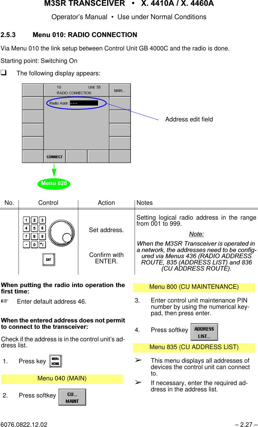
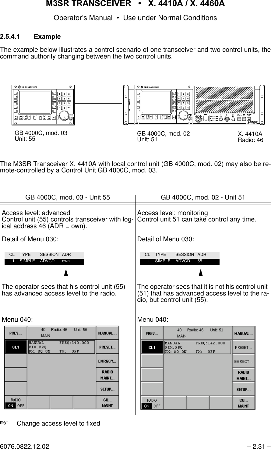
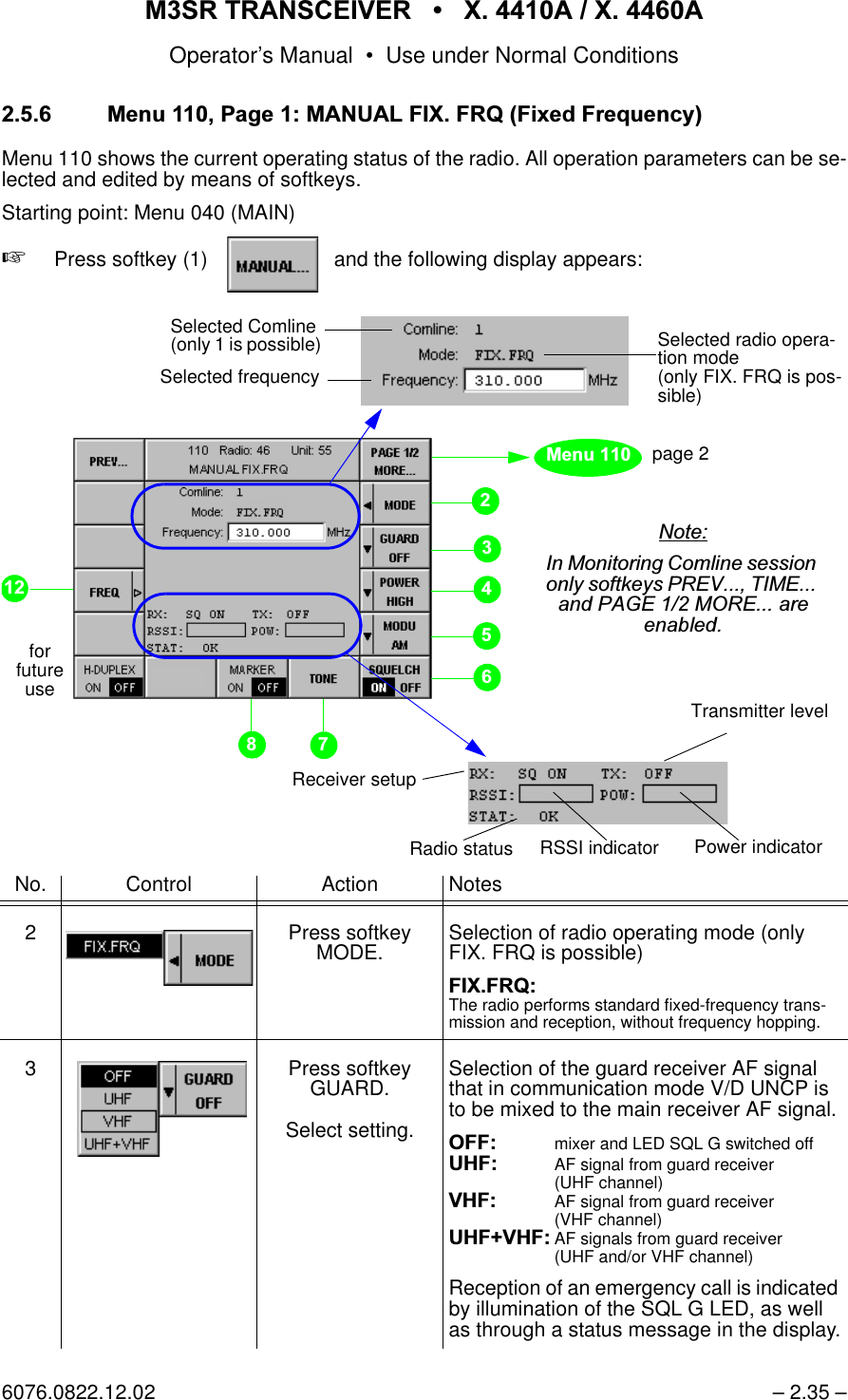
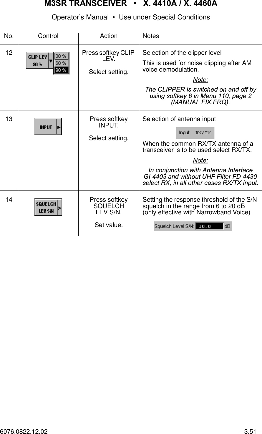
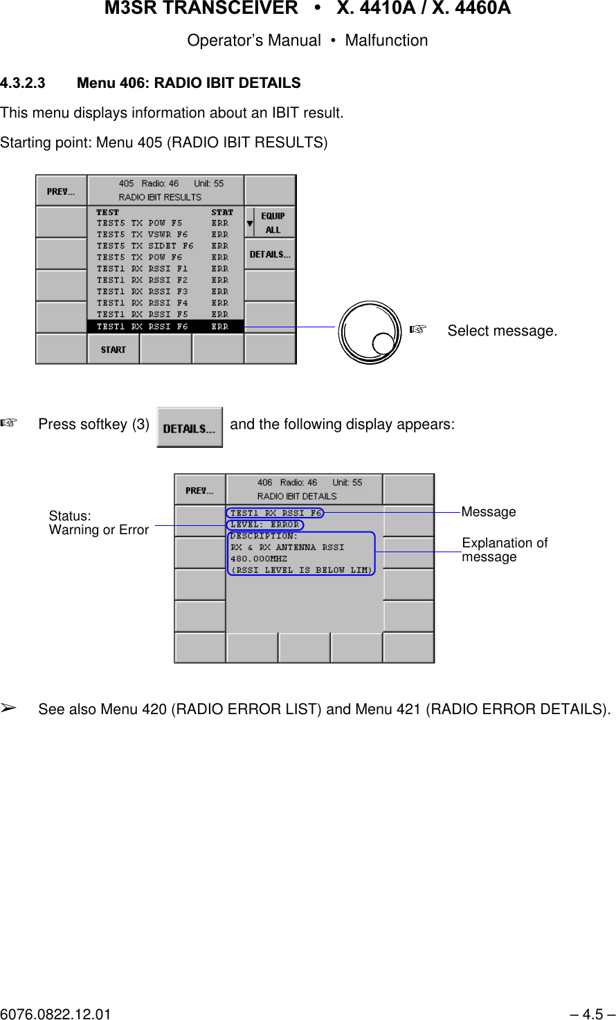
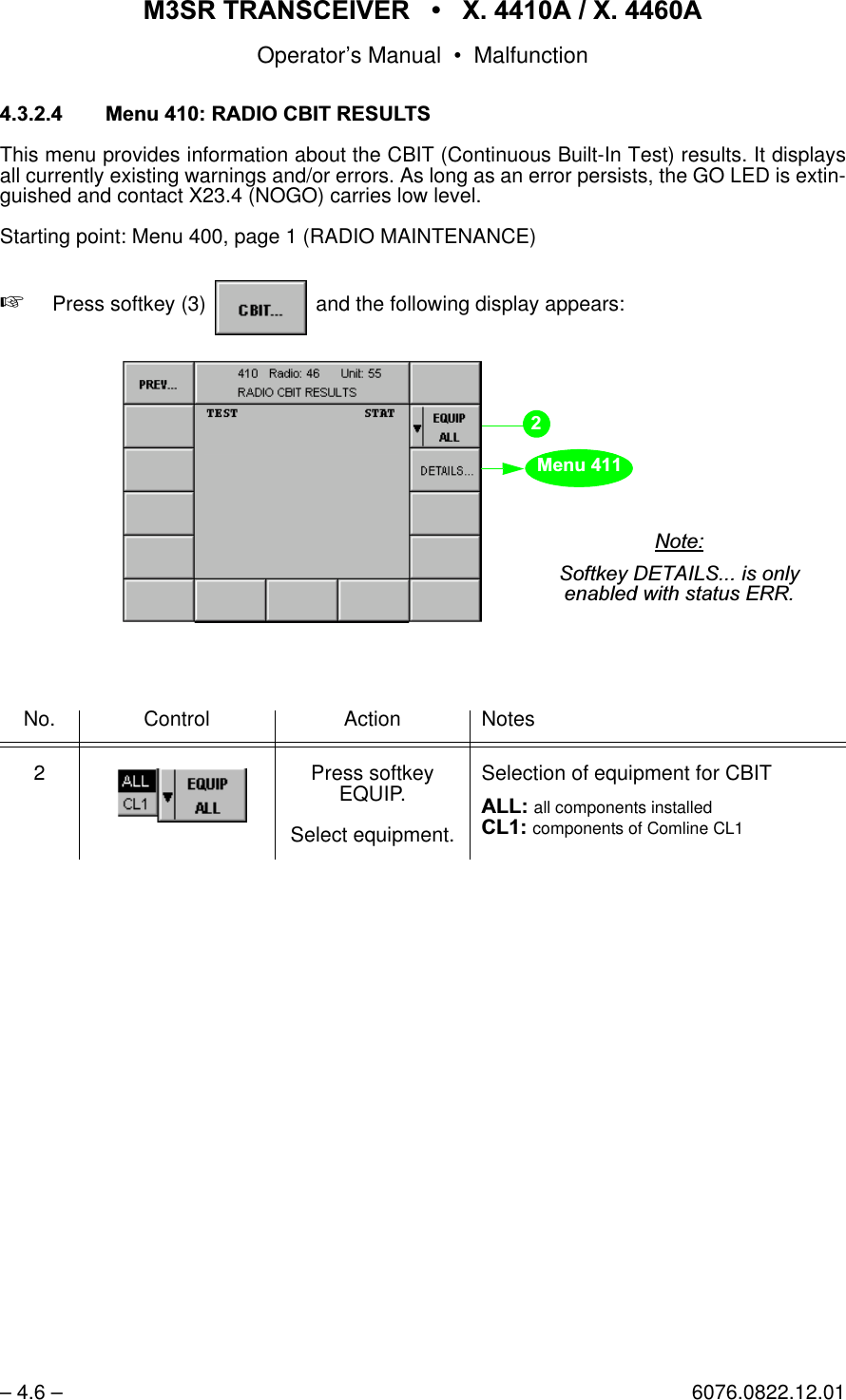
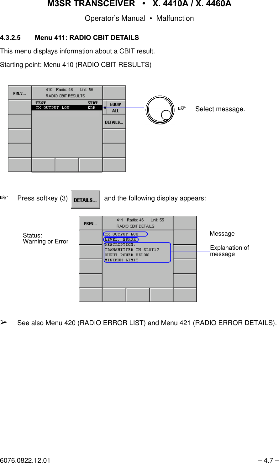
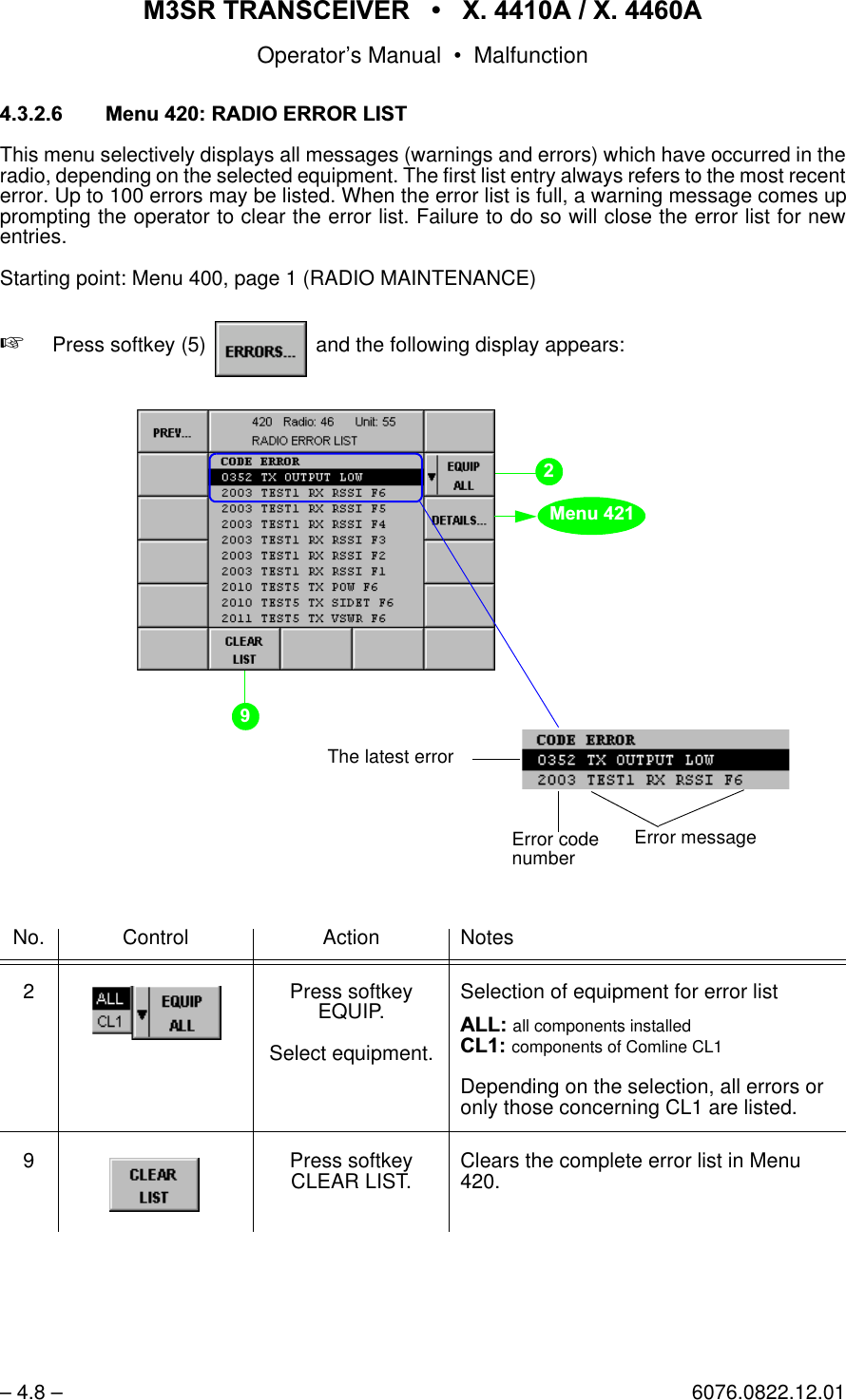
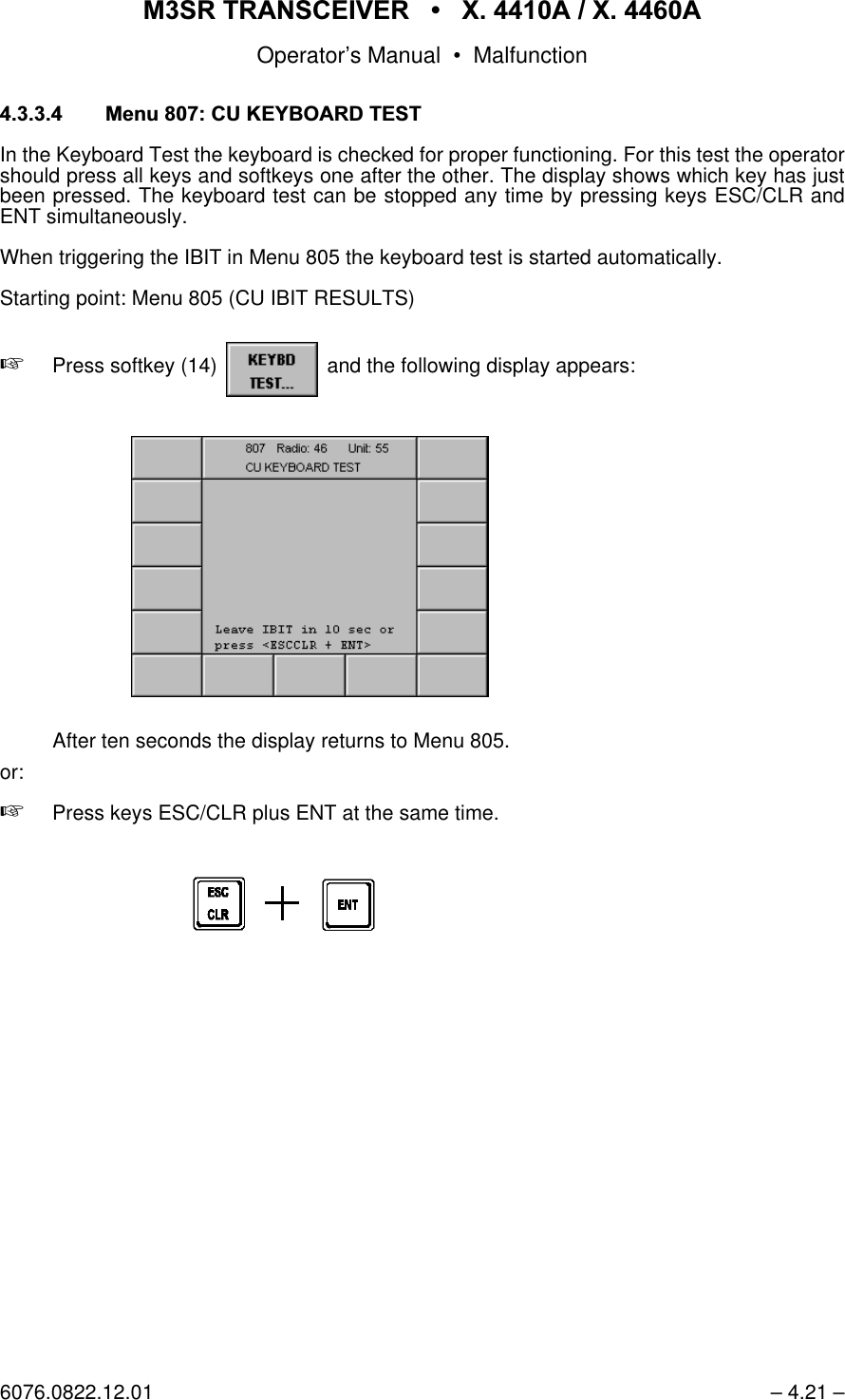
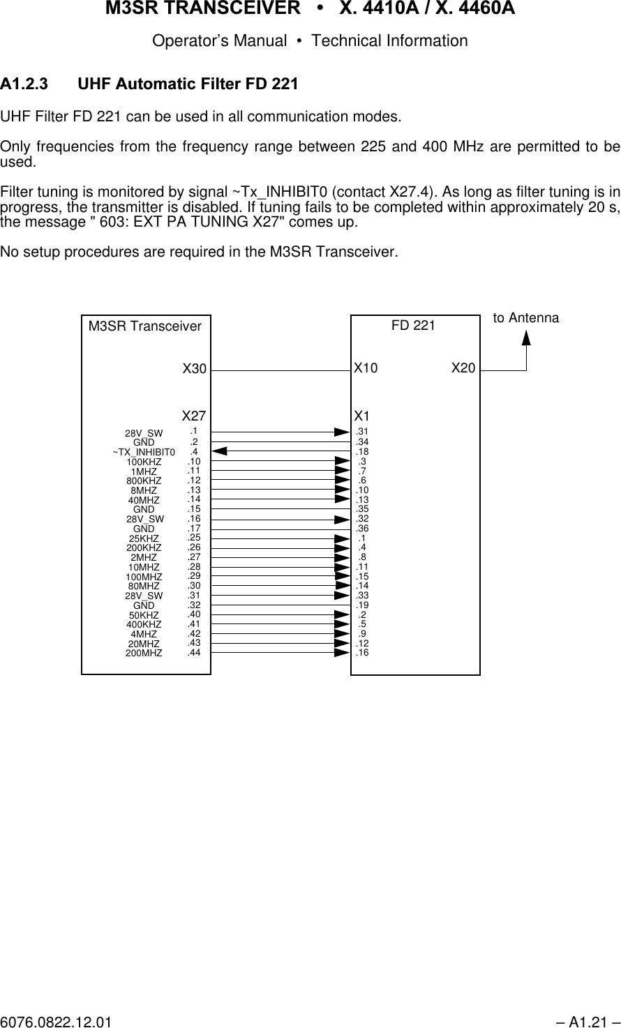
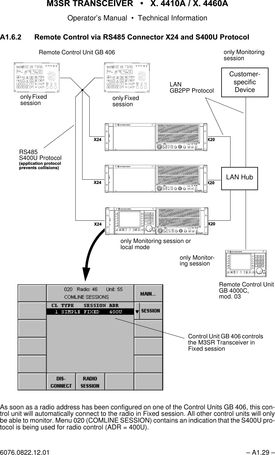
![065 75$16&(,9(5 ; $ ; $Operator’s Manual– V.2 – 6076.0822.12.01+: hardware+:0 hardware module,%,7 initiated built-in test,&$2International Civil AviationOrganization,'identification,'' interface design document,(& International ElectrotechnicalCommittee,(7)Internet engineering task force,)intermediate frequency,)interface,//80illumination,03impedance,1 input,19 inventory,2input/output,3Internet protocol,U'$Infrared Data Association,here also: infrared data access,6'1integrated services digitalnetwork,78International Telecommunic-tions Union (ITU standards).'' key distribution device.('key entry device.(<%'keyboard.)0& key and frequencymanagement center.0& key management center/local/$1 local area network/&$ logic cell array (SW-program-mable gate array)/' low distortion/('light-emitting diode/(9 level/1low noise/2 local oscillator/2&local/2* logical/26line of sight/3 lowpass filter/58line-replaceable unit/6% least significant bit/:low0main receiver065 multiband, multimode andmultirole surface radio0$,17 maintenance0('medium0+6 management and handlingsystem0+] megahertz0,6& miscellaneous00& mission management center00, man-machine interface02' module02'02'8 modulation021,7 monitor05. marker06% most significant bit07%)mean time between failures0775 mean time to repair1 newton1$72North Atlantic TreatyOrganization1% narrowband1( net entry12number2operational2&;2oven-controlled crystaloscillator2))6offset20& operation management center3$power amplifier3$5$06 parameters3%,7 power-on built-in test3&% printed circuit board3,1 personal identification number3// phase-locked loop30phase modulation325plain override 32:power33 preset page330parts per million330pulse per minute336pulse per second35(9 previous352' production3527protection36power supply37plain text377 push to talk3:5 power5radio5$0 random access memory5& remote control5&% radio control bus5'%radio data bus5(& receive5()reference5(0 remote5)radio frequency5)&request for commands5, ring indicator50% radio module bus 566, received signal strengthindicator576 ready to send5; receiver, reception5['receive data61 signal-to-noise ratio6$7851 Second Generation Anti-jamTactical UHF Radio for NATO6(5 serial6,'(71 sidetone6/slot612serial number62&software options controller63spacing6464/squelch648* squelch guard receiver](https://usermanual.wiki/Rohde-and-Schwarz-and-Co-KG/61020307.Revised-Manual/User-Guide-1012212-Page-26.png)
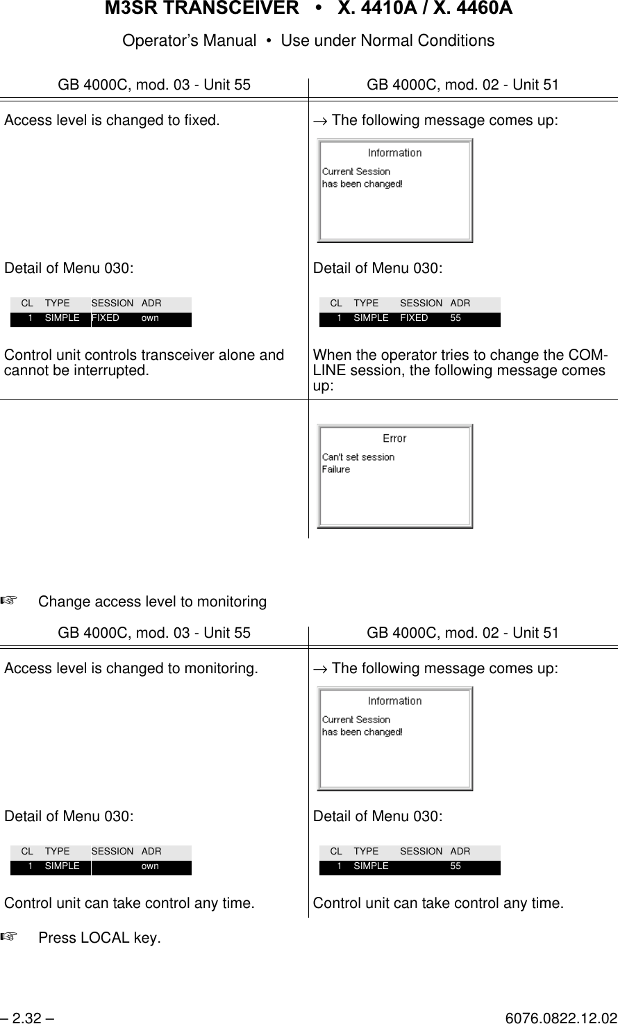
![065 75$16&(,9(5 ; $ ; $Operator’s Manual6076.0822.12.01 – H.1 / H.2 –1RWLFHVThe three different notices used in this Operator’s Manual have the following meaning:7KLVKHDGLQJLVXVHGWRLQGLFDWHWKDWLQDFFXUDWHREVHUYDQFHRUQRQREVHUYDQFHRILQVWUXFWLRQVRUPHWKRGVFDQFDXVHLQMXU\RUHYHQIDWDODFFLGHQWVRUGXULQJDQRSHUDWLRQGHVFULEHGKD]DUGRXVPDWHULDOFDQEHVHWIUHHLQWKHXQLWRUV\VWHP&$87,217KLVKHDGLQJLVXVHGWRLQGLFDWHWKDWLQDFFXUDWHREVHUYDQFHRUQRQREVHUYDQFHRILQVWUXFWLRQVRUPHWKRGVFDQFDXVHGDPDJHWRWKHXQLW1RWH7KLVKHDGLQJLVXVHGWRGUDZWKHUHDGHU¶VDWWHQWLRQWRDSDUWLFXODUIDFWThis manual contains the following ’Warning’::HDUJRJJOHVZKHQZRUNLQJZLWKFRPSUHVVHGDLULQRUGHUWRDYRLGH\HLQMXULHV:$51,1*:$51,1*](https://usermanual.wiki/Rohde-and-Schwarz-and-Co-KG/61020307.Revised-Manual/User-Guide-1012212-Page-31.png)
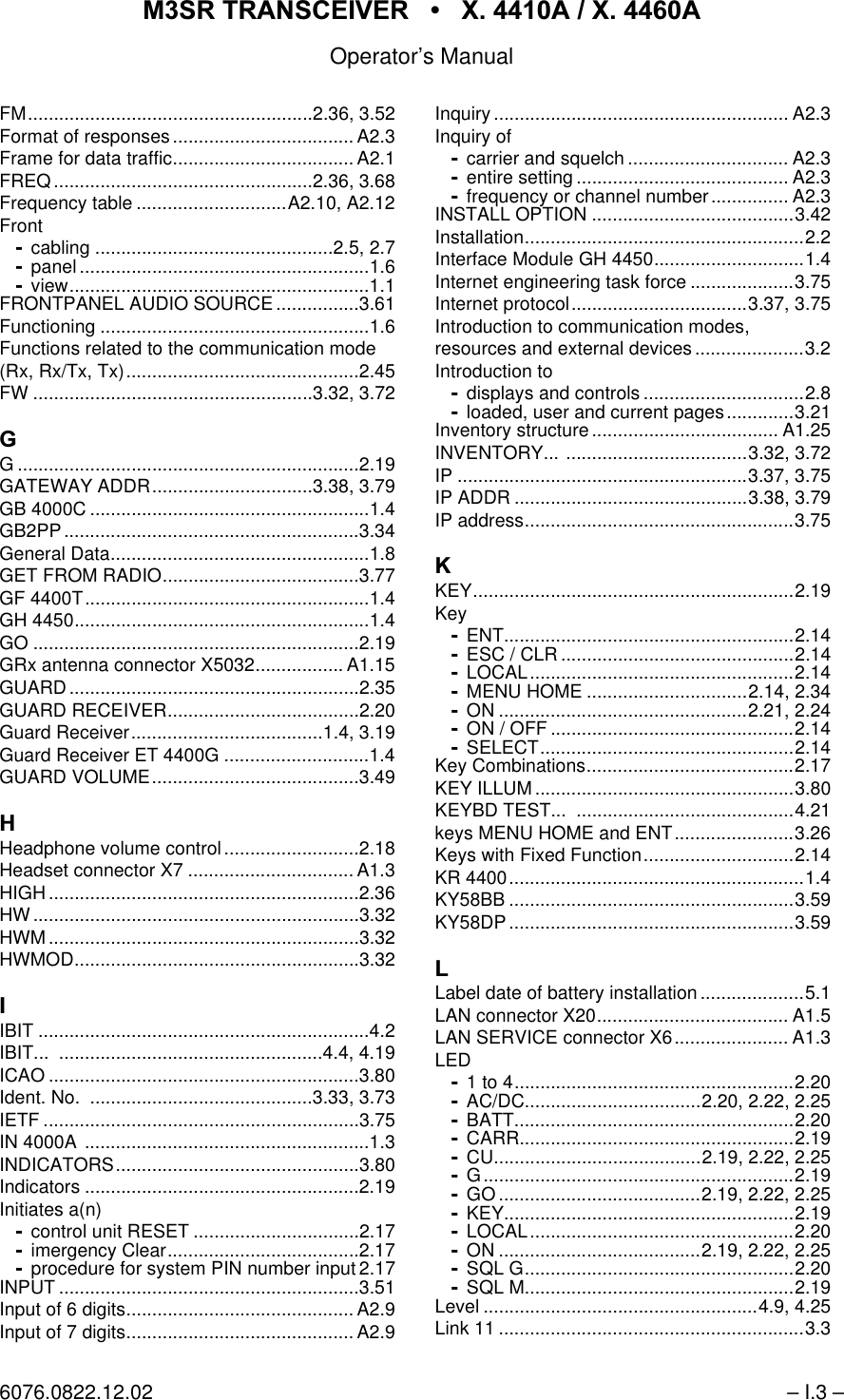
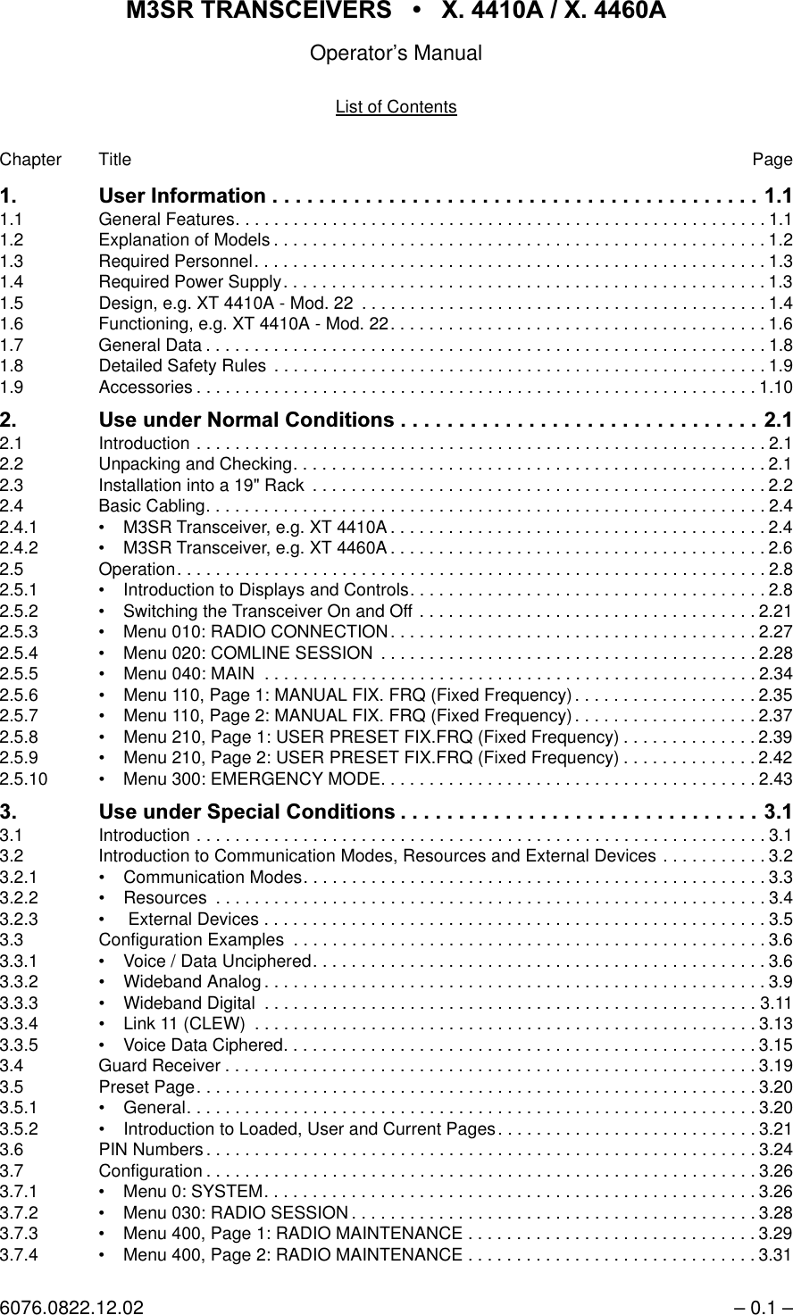
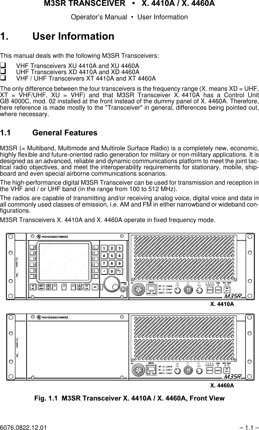
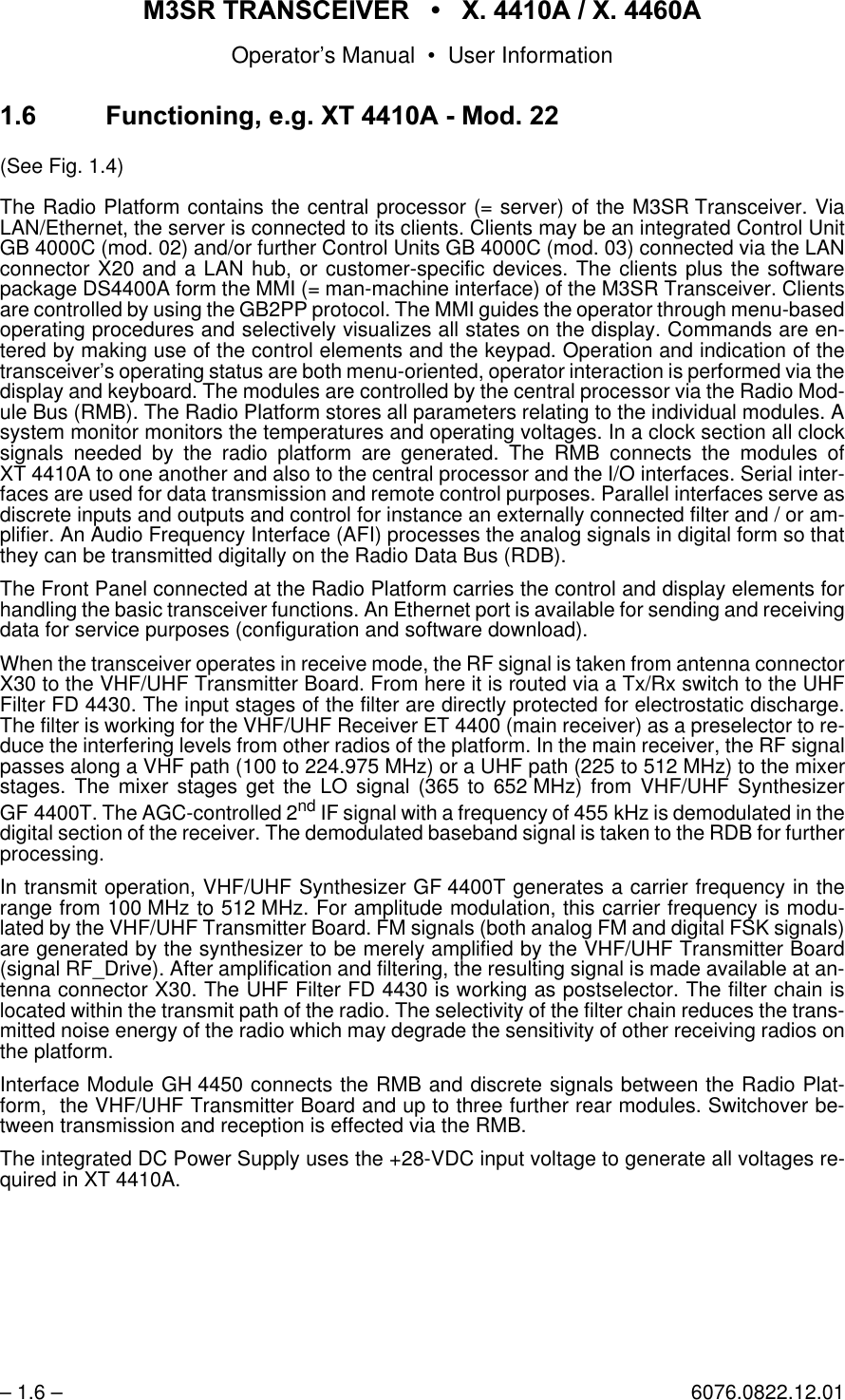
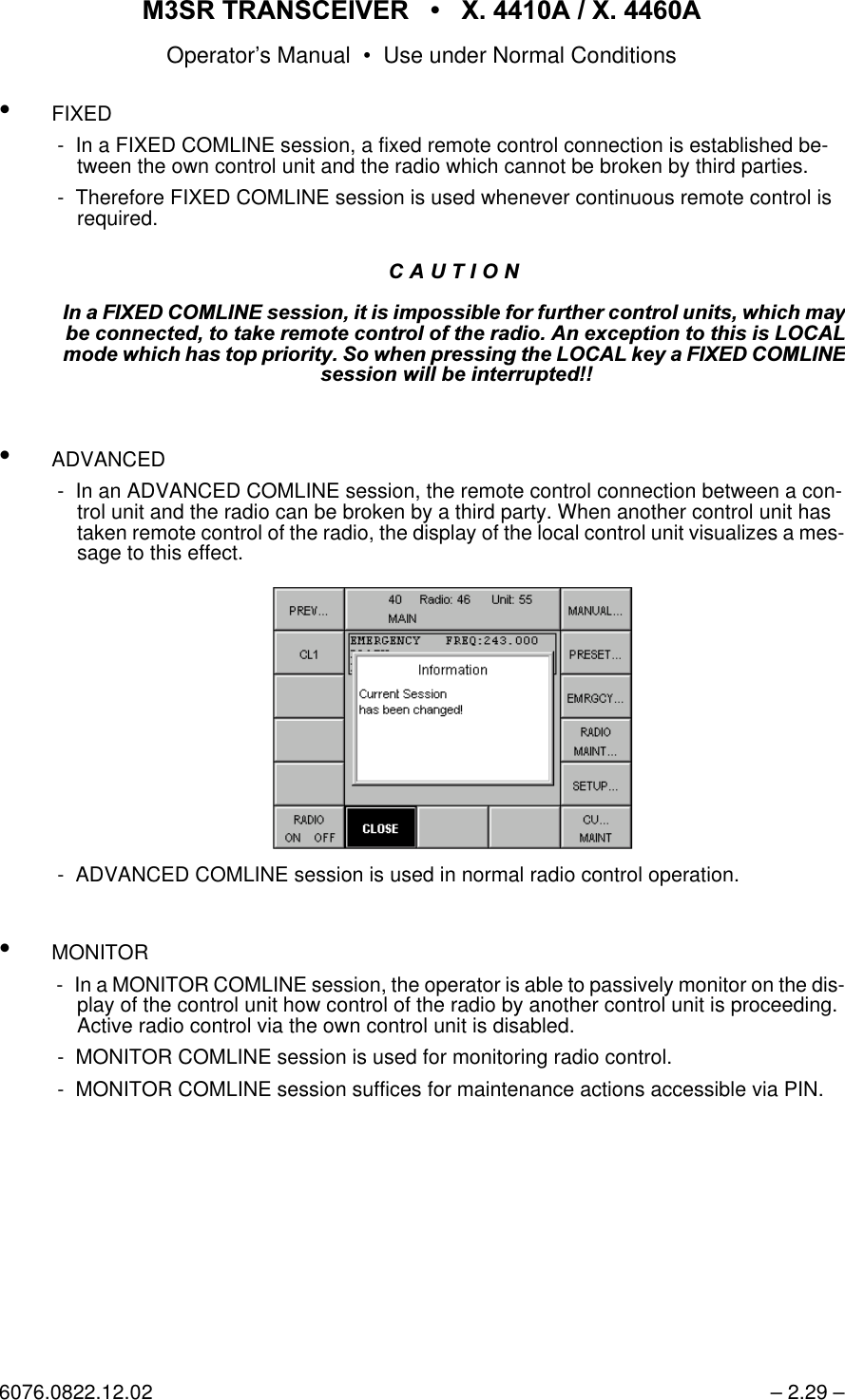
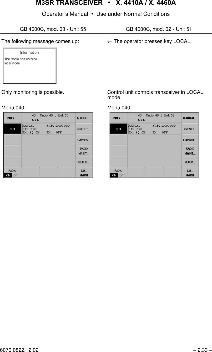
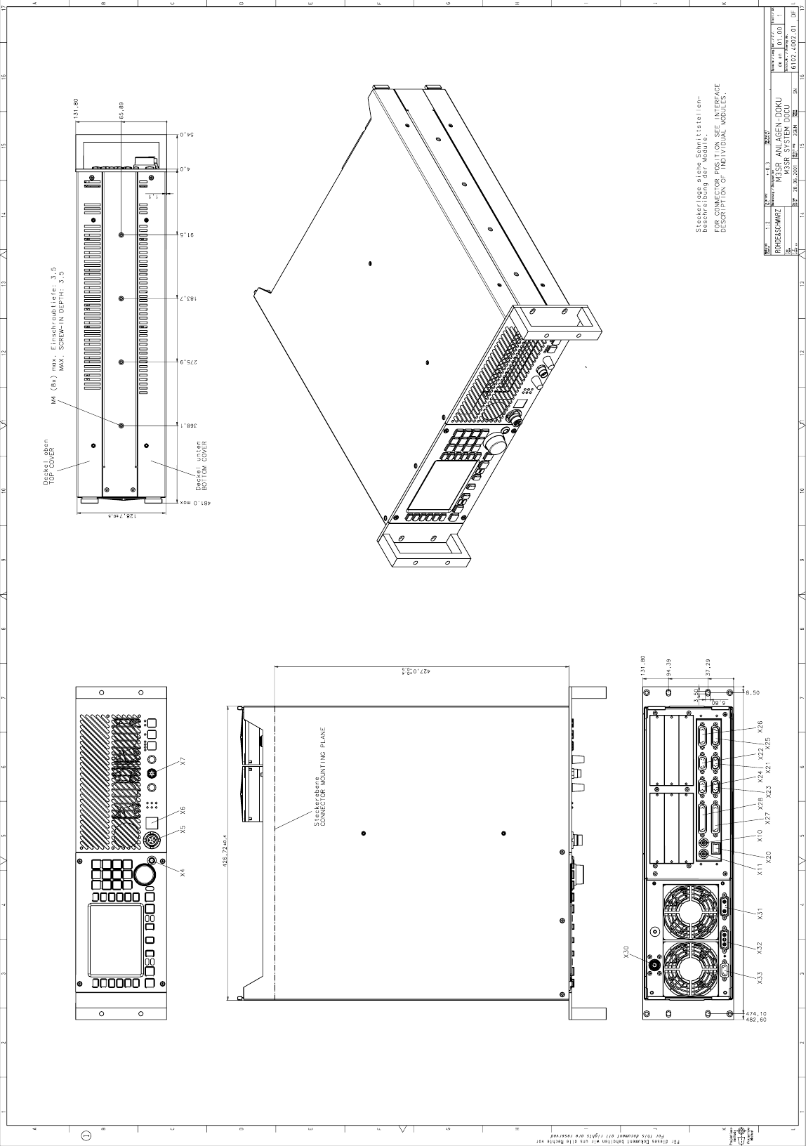
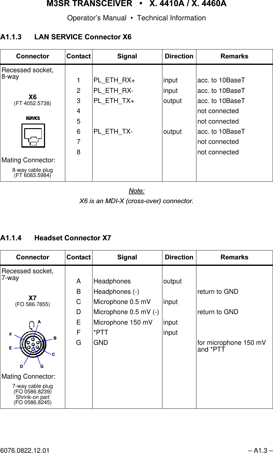
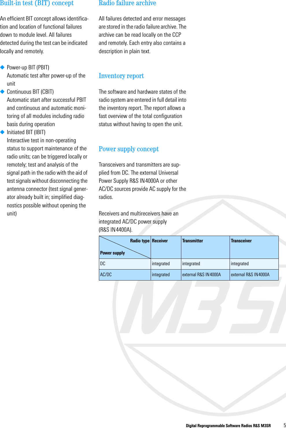
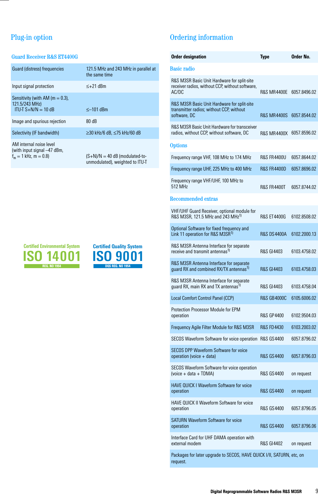
![065 75$16&(,9(5 ; $ ; $Operator’s Manual • User Information6076.0822.12.01 – 1.5 –)LJ 7RS9LHZRIHJ;7 $0RGZLWKRXW&RYHU9+)8+)7UDQVPLWWHU%RDUGwith'&3RZHU6XSSO\underneath(both are part ofTransmitter Unit VT 4403, Mod. 02)+HDWVLQNZLWKWZRIDQV(part of VT 4403, Mod. 02)3RZHUPRGXOHV)URQW3DQHO8QLW(part of KR 4400),QWHUIDFH0RGXOH*+ 9+)8+)6\QWKHVL]HU*) 73OXJLQPRGXOHV9+)8+)5HFHLYHU(7 )UDPH(part of Ra-dio Basis KR 4400)5DGLR3ODWIRUP(part of KR 4400)&RQWURO8QLW*%&0RG1RWH5DGLRSODWIRUPFRQQHFWRUVVKRZQZLWKRXWSURWHFWLYHFDSV8+))LOWHU)' ](https://usermanual.wiki/Rohde-and-Schwarz-and-Co-KG/61020307.Revised-Manual/User-Guide-1012212-Page-55.png)
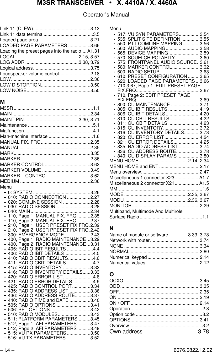
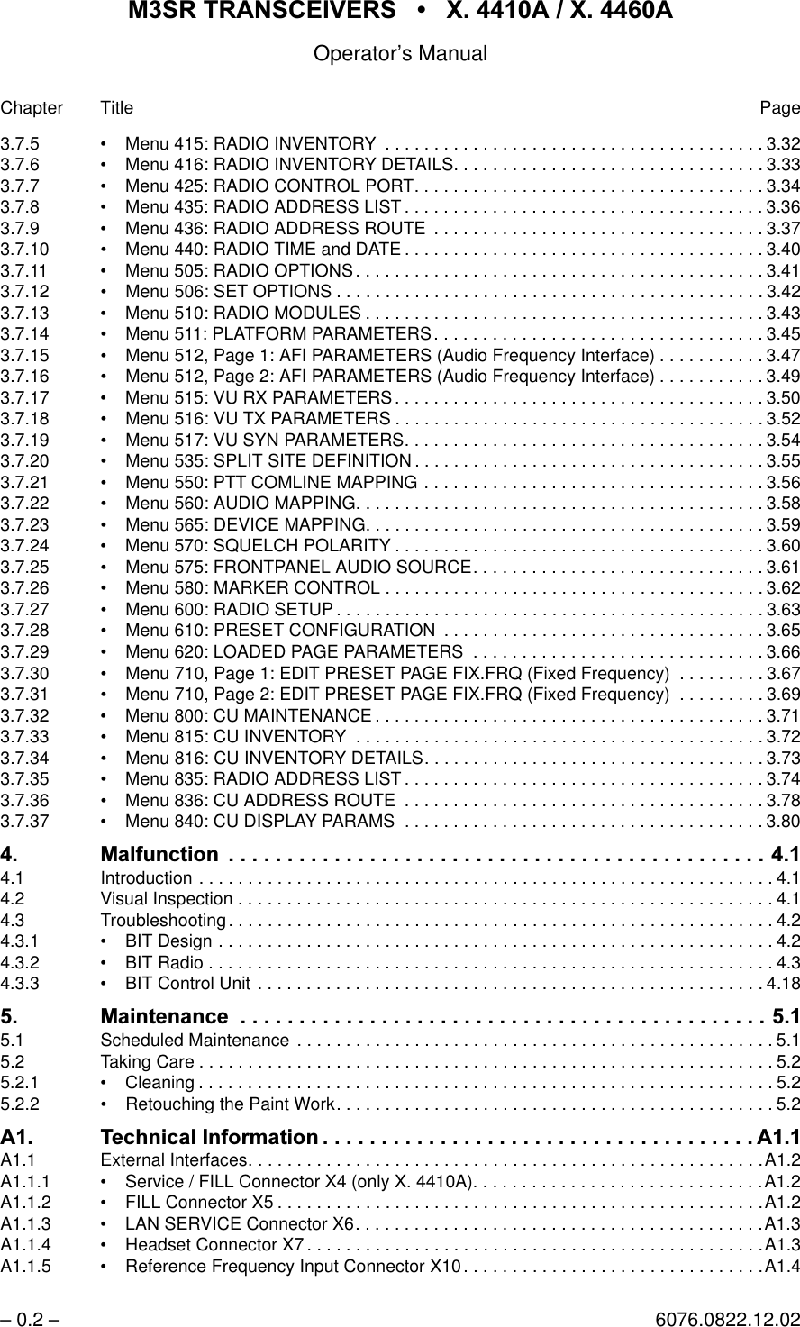
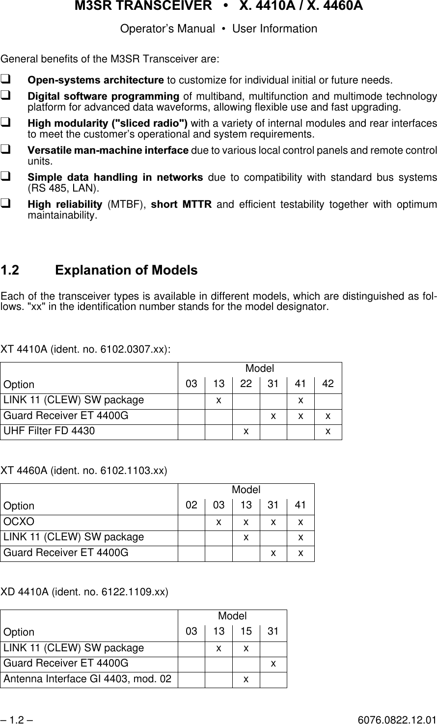
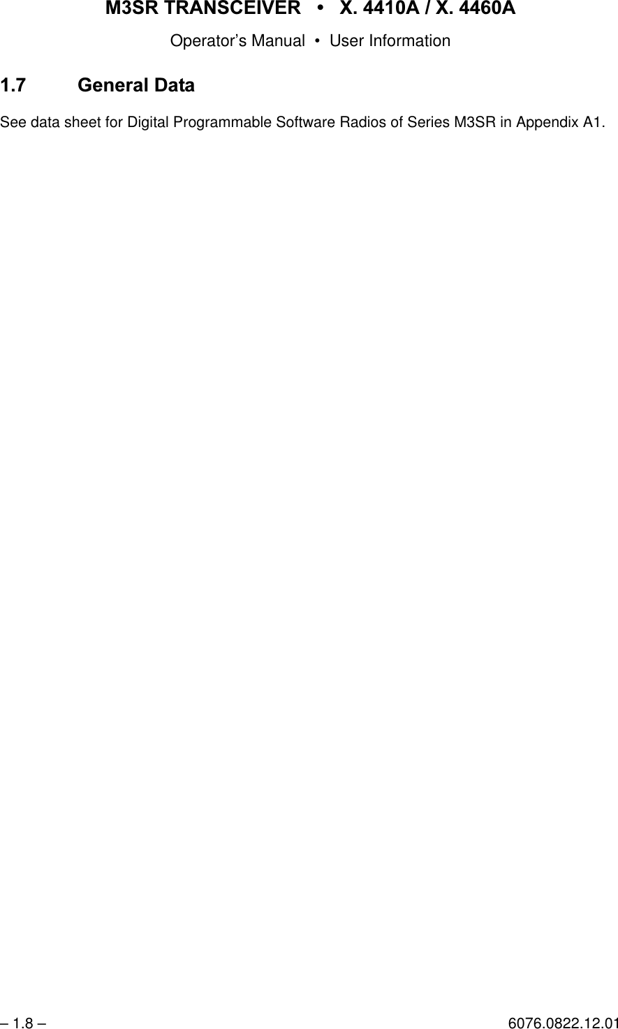
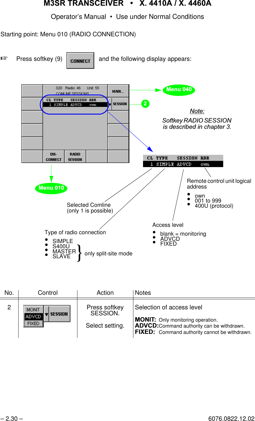
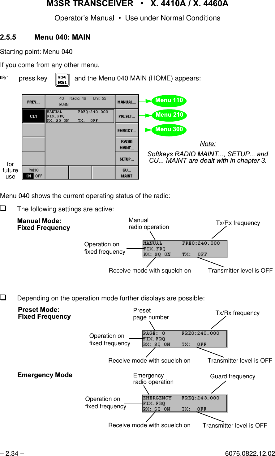
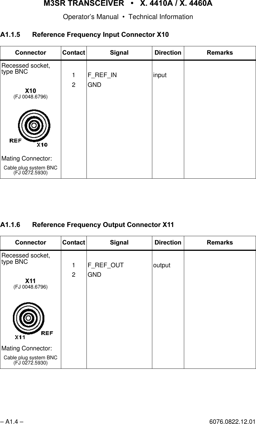
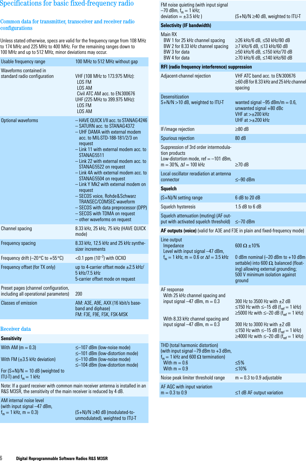
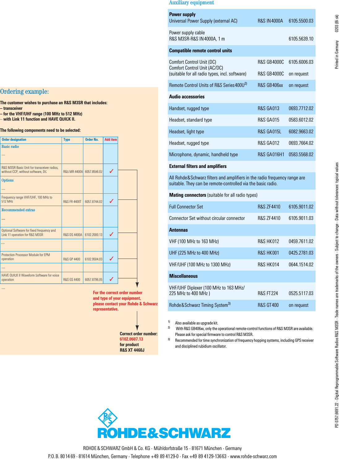
![065 75$16&(,9(5 ; $ ; $Operator’s Manual • User Information6076.0822.12.01 – 1.7 –)LJ %ORFN'LDJUDPRIHJ;7 $0RG&RQWURO8QLW9+)8+)5HFHLYHU(7 9+)8+)6\QWKHVL]HU*) 7*%&0RG5DGLR 3ODWIRUP5()B,1 ;5()B287 ;$PS)LO;$PS)LO ;0LVF ;0LVF;56 ;56 ;$);$);'LVSOD\ .H\ERDUG.'' ;.'' ;(WKHUQHW ; +HDGVHW ;5[(WKHUQHW ;)URQW 3DQHOµ&&ORFN50%$XGLR,2,QWHUIDFHV6HULDO3DUDOOHO(WKHUQHW)UHTXHQF\,QWHUIDFH6HFWLRQ5DGLR %DVLV.5 6HUYHU&OLHQW(WKHUQHW(WKHUQHW8+))LOWHU)' /2B5[,QWHUIDFH%RDUG*+ %$77(5< ;5)B'ULYH9+)8+)7UDQVPLWWHU%RDUG'&3RZHU6XSSO\'&B,1 ;&21752/;$QWHQQD ;7UDQVPLWWHU 8QLW97 5[B,Q7[B,Q7[B2XW5[B2XW](https://usermanual.wiki/Rohde-and-Schwarz-and-Co-KG/61020307.Revised-Manual/User-Guide-1012212-Page-57.png)
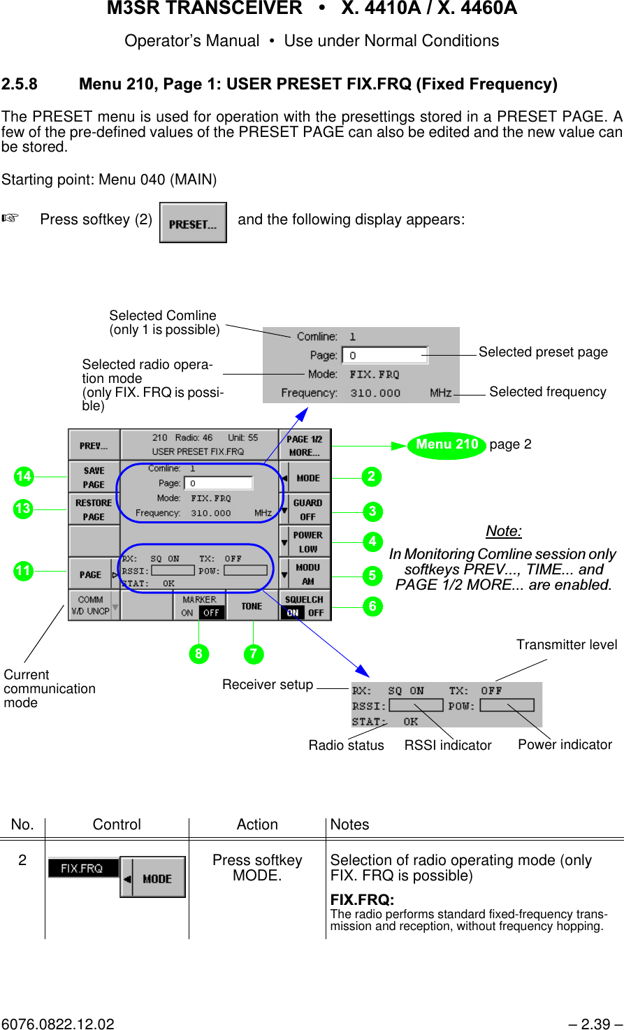
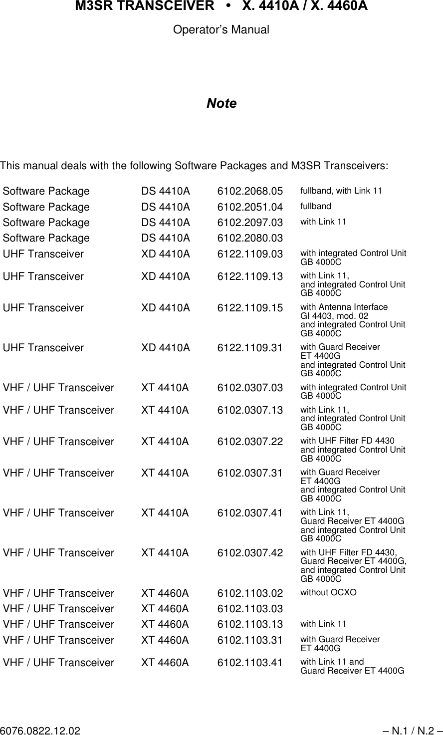
![065 75$16&(,9(5 ; $ ; $Operator’s Manual • Use under Normal Conditions6076.0822.12.02 – 2.43 / 2.44 – 0HQX(0(5*(1&<02'(In the EMERGENCY menu, frequency band and transmit power for making an emergency callcan be selected. Reception of an emergency call is indicated by illumination of the SQL G LED,as well as through a status message in the display. When the operator then changes to theEMERGENCY menu, that frequency where the call was received on will be automatically set.Then the operator only has to press the PTT key to answer the emergency call. Depending onthe configuration in Menu 575 (FRONTPANEL AUDIO SOURCE), the emergency call will alsobe made audible via the loudspeaker. Softkey GUARD (see Menu 110, page 1 (MANUALFIX.FRQ) and Menu 210, page 1 (USER PRESET FIX.FRQ)) is used to select the guard re-ceiver AF signal that in communication mode V/D UNCP is to be mixed to the main receiver AFsignal on the Comline.Starting point: Menu 040 (MAIN)+Press softkey (3) qThe following display appears:No. Control Action Notes2 Press softkey BAND to select the required band.Tunes to emergency frequency of transmit-ter (VHF or UHF):VHF = 121.500 MHzUHF = 243.000 MHz 1RWH:KHQWKHUDGLRUHFHLYHVDQHPHUJHQF\FDOOHJRQ0+]DQGWKHRSHUDWRUWKHQFKDQJHVWR0HQXWKHIUHTXHQF\RI0+]ZLOOEHWXQHGDXWRPDWLFDOO\+RZHYHULIWKHRSHUDWRUVWLOOZDQWVWRVHOHFW0+]WKHQKHRQO\QHHGVWRSUHVVVRIWNH\%$1'3 Press softkey POWER to select the required power level.Selection of emergency transmit power2)) Tx is switched off/2: Tx is set to low power0(',80Tx is set to medium power+,*+ Tx is set to high powerÇThe exact levels in W are set in Menu 516 (VU TX PARAMETERS).Guard receiver bandSelected ComlineTransmit power levelSelected guard frequency](https://usermanual.wiki/Rohde-and-Schwarz-and-Co-KG/61020307.Revised-Manual/User-Guide-1012212-Page-103.png)
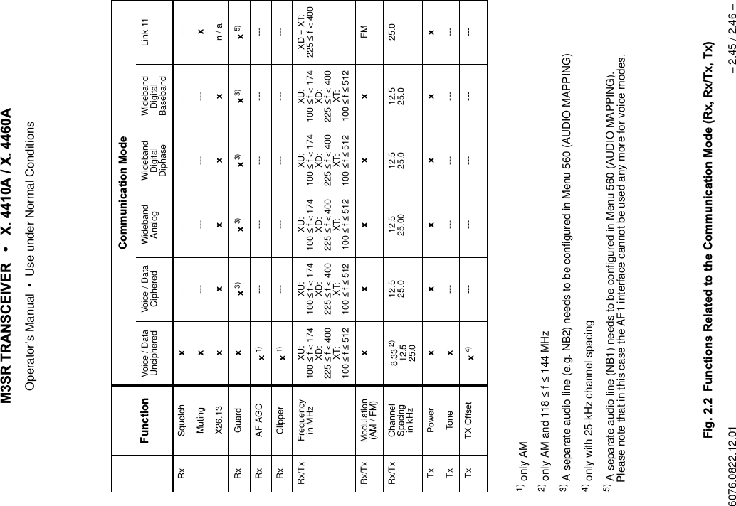
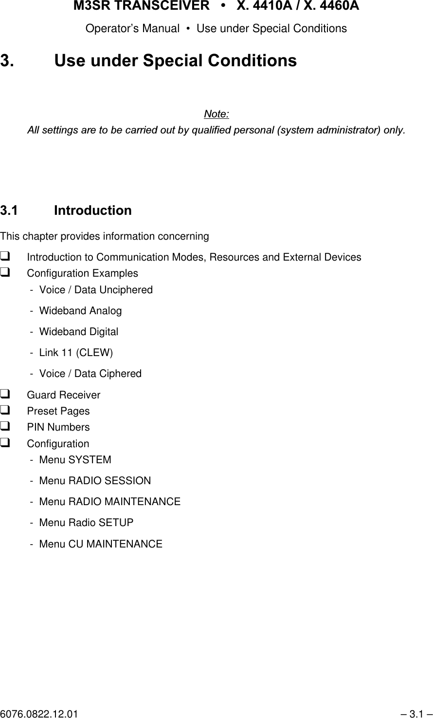
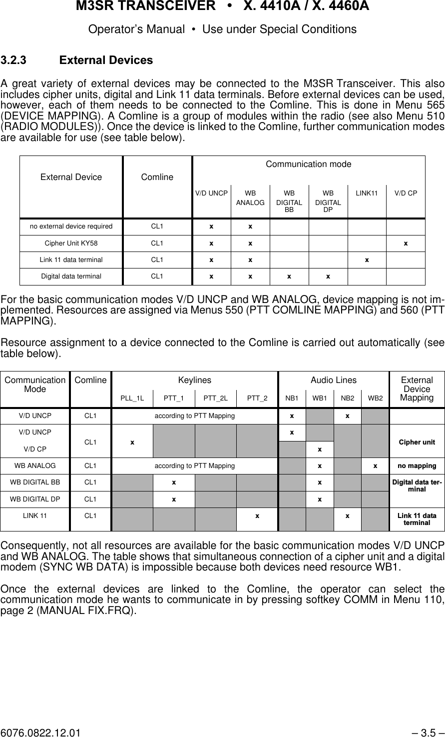
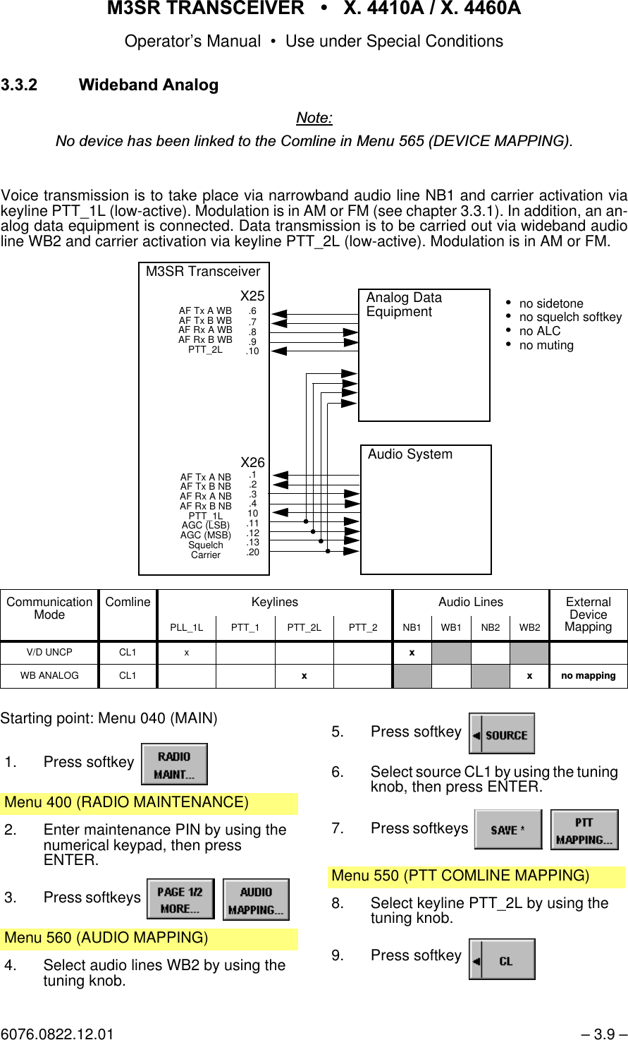
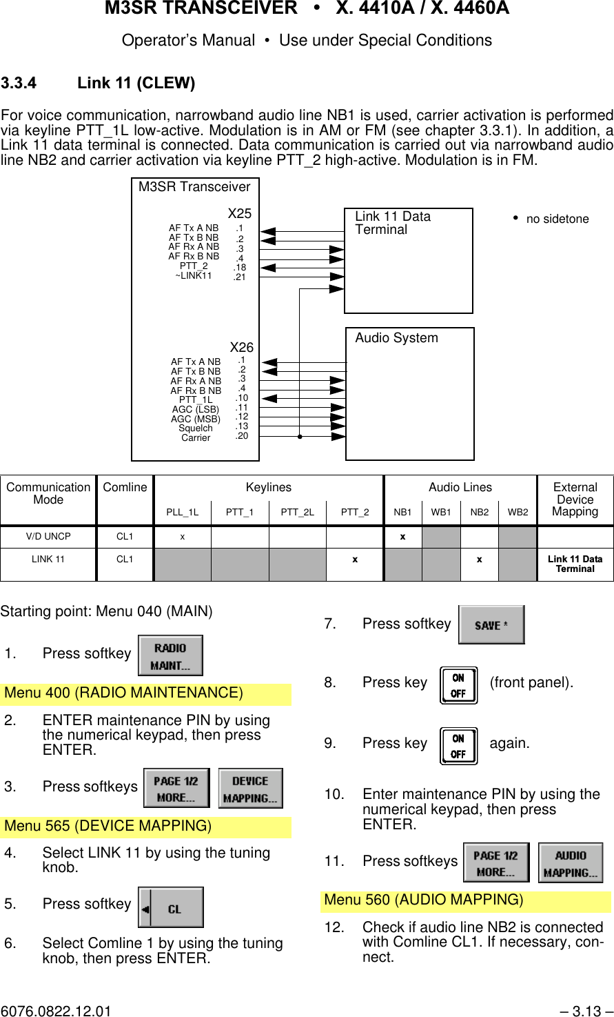
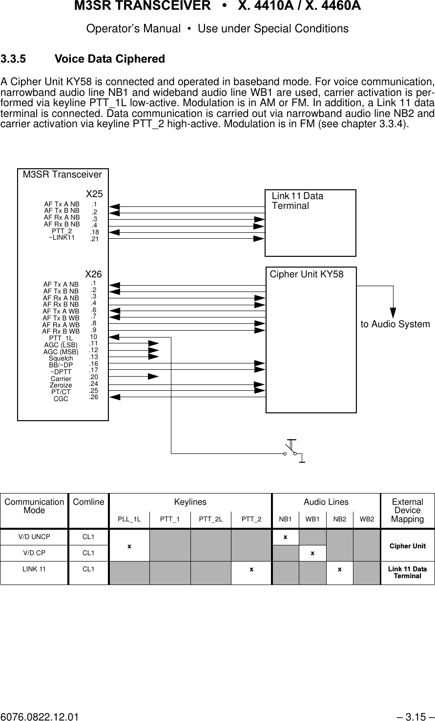
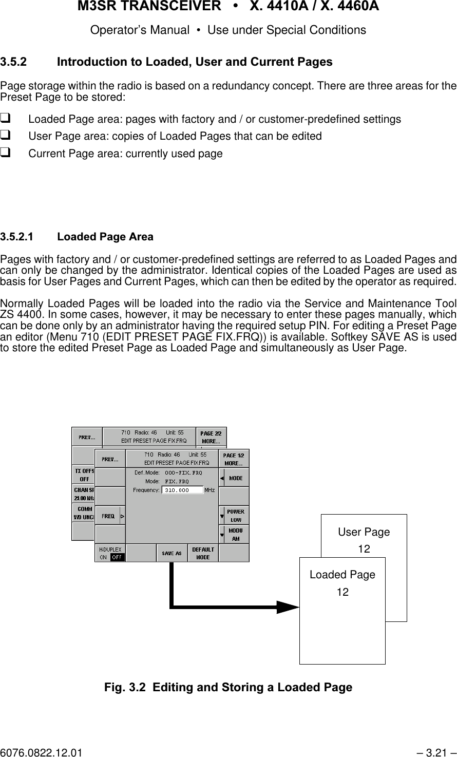
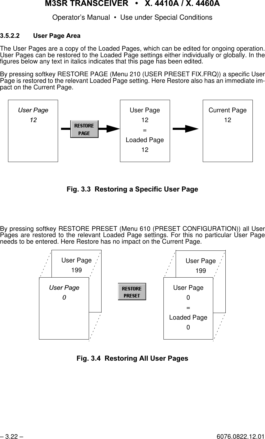
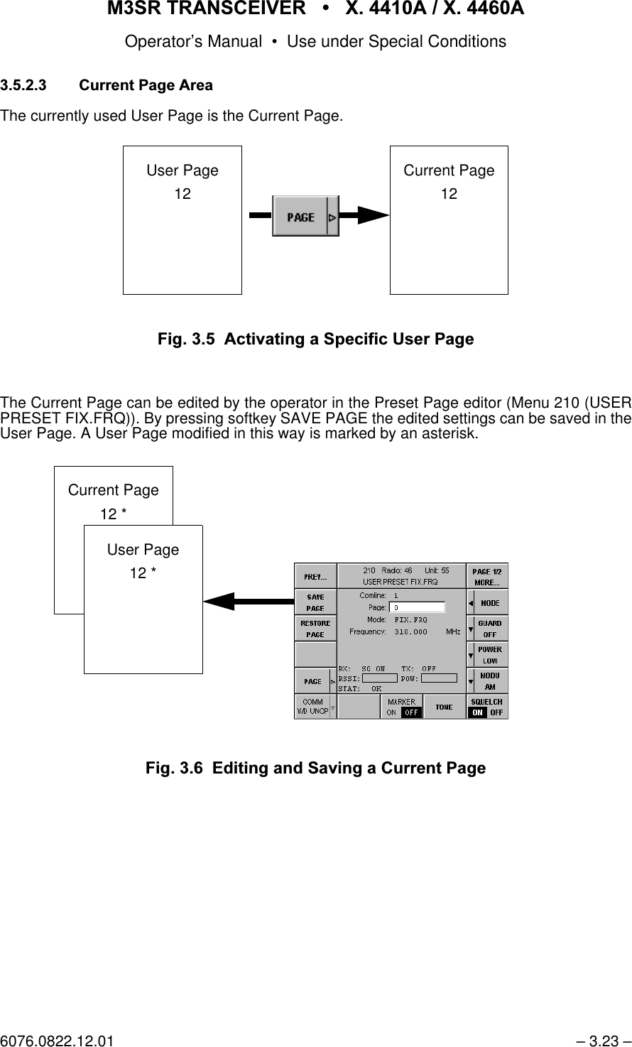
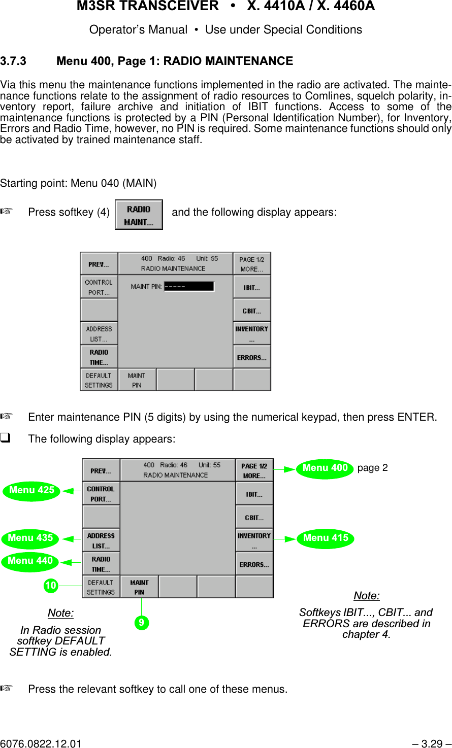
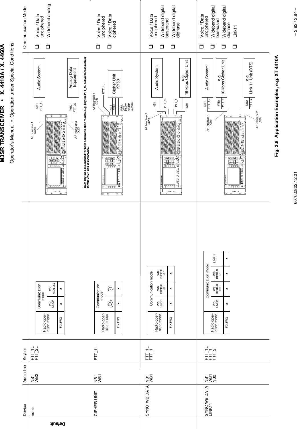
![065 75$16&(,9(5 ; $ ; $Operator’s Manual • Use under Special Conditions6076.0822.12.01 – 3.3 – &RPPXQLFDWLRQ0RGHVDepending on the option codes, the external devices connected at the Comline and the cur-rently active radio mode, one or several of the following communication modes are available: qVoice / Data Unciphered (V/D UNCP):The communication mode V/D UNCP is used for narrowband AM and FM voice commu-nication. The keyline selected by PTT mapping is used. Narrowband audio lines NB1 andNB2 are available. Audio line NB1 should be used by preference.qWideband Analog (WB ANALOG)The communication mode WB ANALOG is used for wideband AM and FM communica-tion with analog data terminals (only baseband). The keyline selected by PTT mappingis used. Wideband audio lines WB1 and WB2 are available. Audio line WB2 should beused by preference.qWideband Digital Baseband (WB DIGITAL BB) andWideband Digital Diphase (WB DIGTAL DP)The communication modes WB DIGITAL are used for data communication (ASK, FSK)with digital data terminals (baseband and diphase). Carrier activation for transmission iscarried out via keyline PTT_1, and the digital data are transmitted via wideband audio lineWB1.qLink 11 (LINK 11)The communication mode LINK 11 is used for data communication with Link 11 data ter-minals. Carrier activation for transmission is carried out via keyline PTT_2, and the dataare transmitted via narrowband audio line NB2.qVoice / Data Ciphered (V/D CP)The voice encrypted by Cipher Unit KY 58 is transmitted via wideband audio line WB1.Carrier activation for transmission is carried out via keyline PTT_1L. The KY 58 and theM3SR Transceiver are interconnected via the following signals:The following table illustrates how the radio operation mode is related to the communicationmode:1RWH:KHQFKDQJLQJWRDGLIIHUHQWFRPPXQLFDWLRQPRGHHJLQ0HQX0$18$/),;)54IXUWKHUSDUDPHWHUVPD\EHFKDQJHGDXWRPDWLFDOO\:KHQFKDQJLQJIURP9RLFH'DWD8QFLSKHUHGPRGXODWLRQPRGH$0FKDQQHOVSDFLQJN+]WR/LQNPRGXODWLRQPRGH)0DQGFKDQQHOVSDFLQJRIN+]ZLOOEHVHW+RZHYHUFKDQJLQJEDFNWR9RLFH'DWD8QFLSKHUHGZLOOQRWUHHVWDEOLVKWKHLQLWLDOVHWWLQJVRIPRGXODWLRQPRGHDQGFKDQQHOVSDFLQJ•CGC (cipher ground control) •BB/DP (baseband / diphase)•DPTT (delayed PTT) •ZEROIZE •PT/CT (plain text / cipher text)Radio operation modeCommunication modeV/D UNCP WBANALOGWBDIGITAL BBWBDIGITAL DPLINK11 V/D CPFIX.FRQ [[[[[[](https://usermanual.wiki/Rohde-and-Schwarz-and-Co-KG/61020307.Revised-Manual/User-Guide-1012212-Page-117.png)
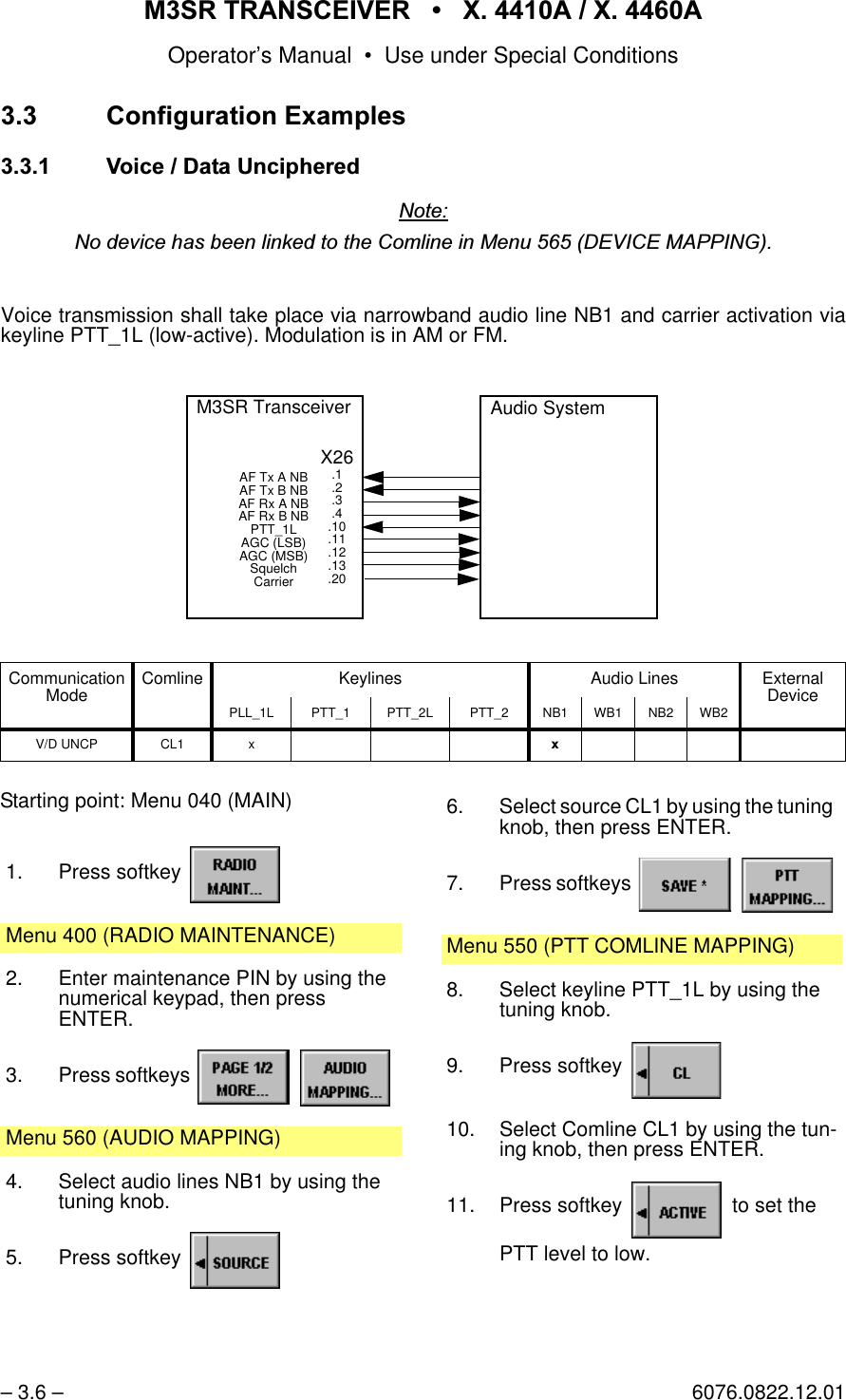
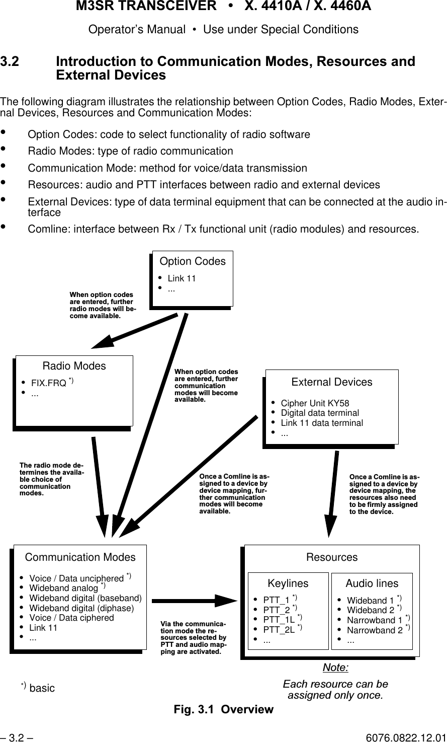
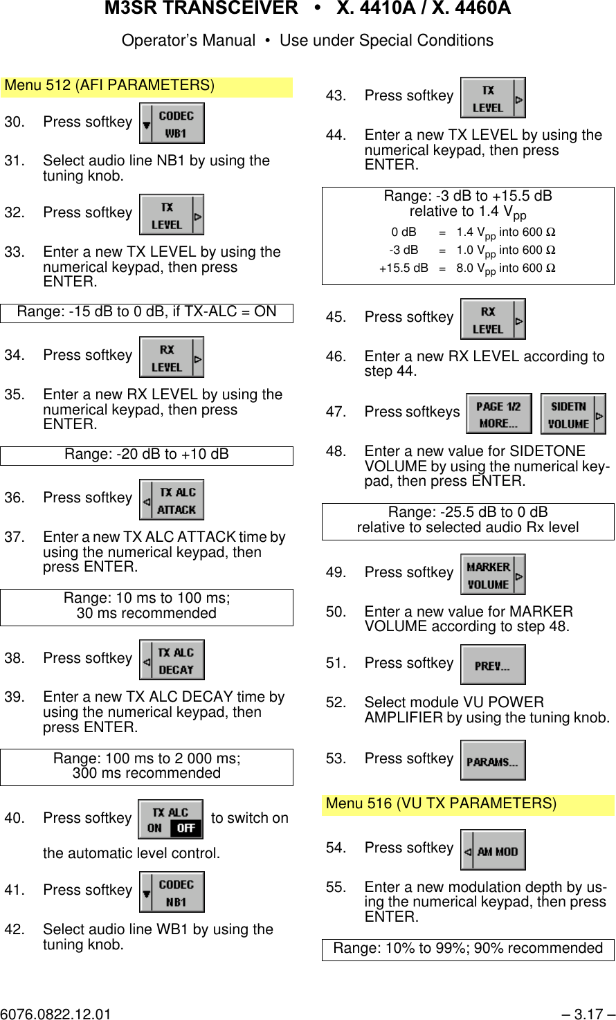
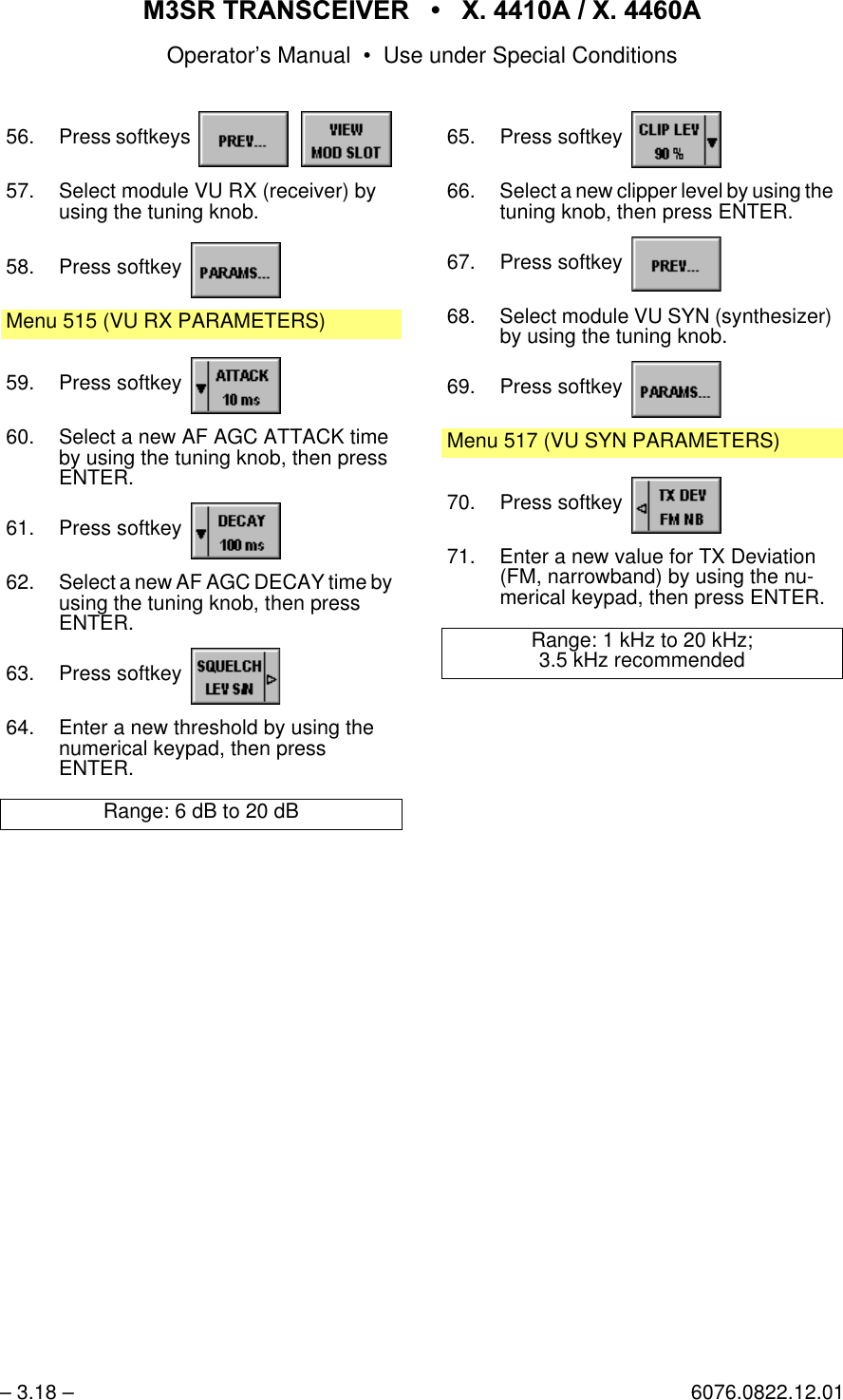
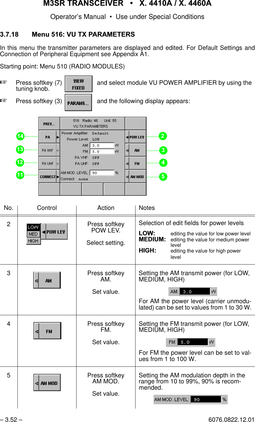
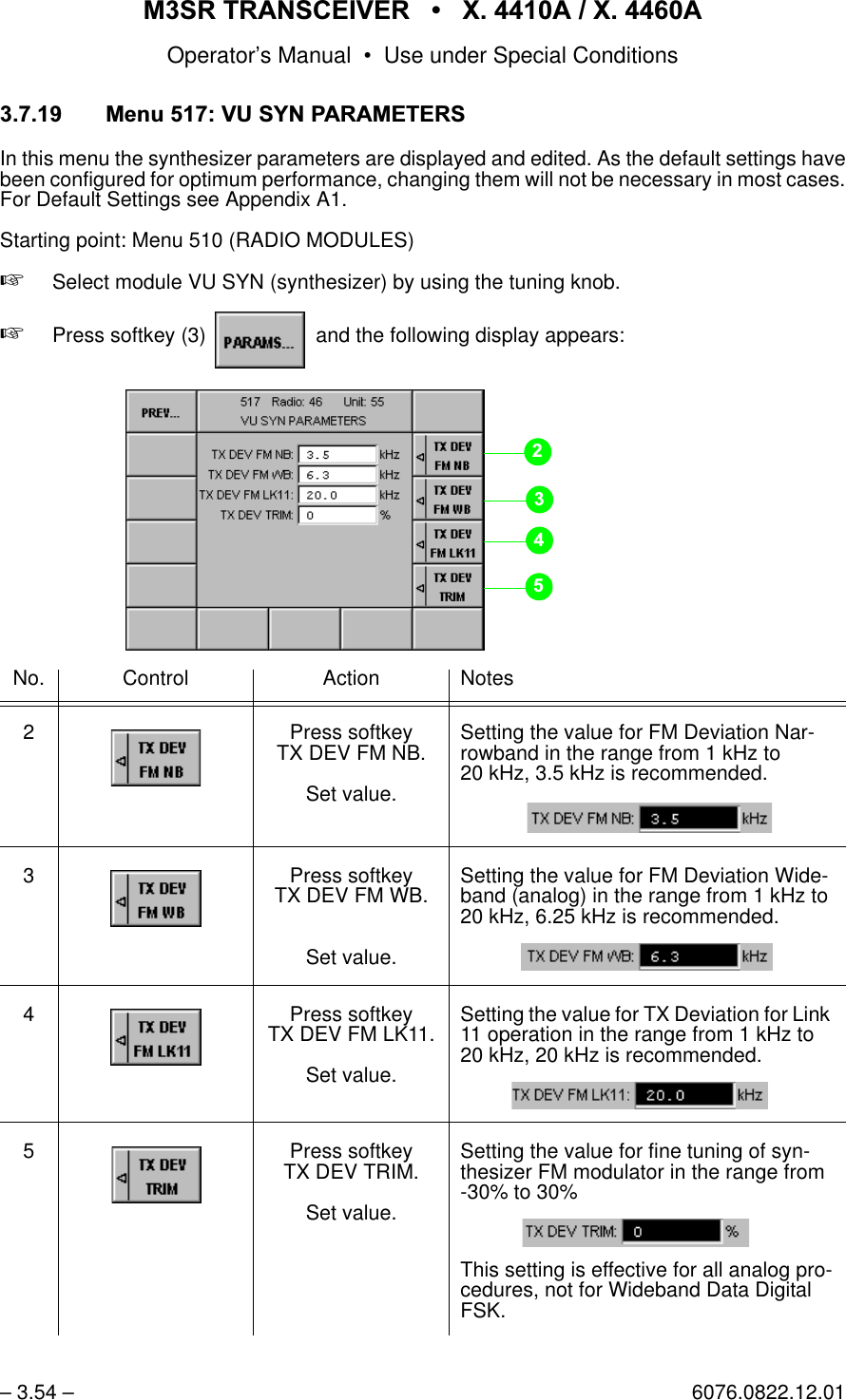
![065 75$16&(,9(5 ; $ ; $Operator’s Manual • Use under Special Conditions– 3.10 – 6076.0822.12.0110. Select Comline CL1 by using the tun-ing knob, then press ENTER.11. Press softkey to set thePTT level to low.12. Press softkeysMenu 570 (SQUELCH POLARITY)13. Select squelch SQ COMLINE 1 by us-ing the tuning knob.14. Press softkey to set thesquelch level to low.15. Press softkeys Menu 510 (RADIO MODULES)16. Press softkey 17. Select module audio interface by us-ing the tuning knob.18. Press softkey Menu 512 (AFI PARAMETERS)19. Press softkey 20. Select audio line WB2 by using the tuning knob.21. Press softkey 22. Enter a new TX LEVEL by using the numerical keypad, then pressENTER.Range: -3 dB to +15.5 dBrelative to 1.4 Vpp0 dB = 1.4 Vpp into 600 Ω-3 dB = 1.0 Vpp into 600 Ω+15.5 dB = 8.0 Vpp into 600 Ω23. Press softkey 24. Enter a new RX LEVEL according to step 22.25. Press softkey 26. Select module VU POWERAMPLIFIER by using the tuning knob.27. Press softkey Menu 516 (VU TX PARAMETERS)28. Press softkey 29. Enter a new modulation depth by us-ing the numerical keypad, then press ENTER.Range: 10% to 99%; 90% recommended1RWH)UHTXHQF\UDQJH +]WRN+]30. Press softkey 31. Select module VU SYN (synthesizer) by using the tuning knob.32. Press softkey Menu 517 (VU SYN PARAMETERS)33. Press softkey 34. Enter a new value for TX Deviation (FM, wideband) by using the numeri-cal keypad, then press ENTER.Range: 1 kHz to 20 kHz;6.25 kHz recommended1RWH)UHTXHQF\UDQJH +]WRN+]](https://usermanual.wiki/Rohde-and-Schwarz-and-Co-KG/61020307.Revised-Manual/User-Guide-1012212-Page-124.png)
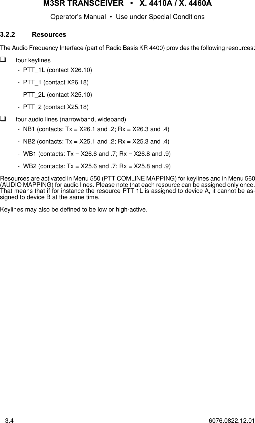
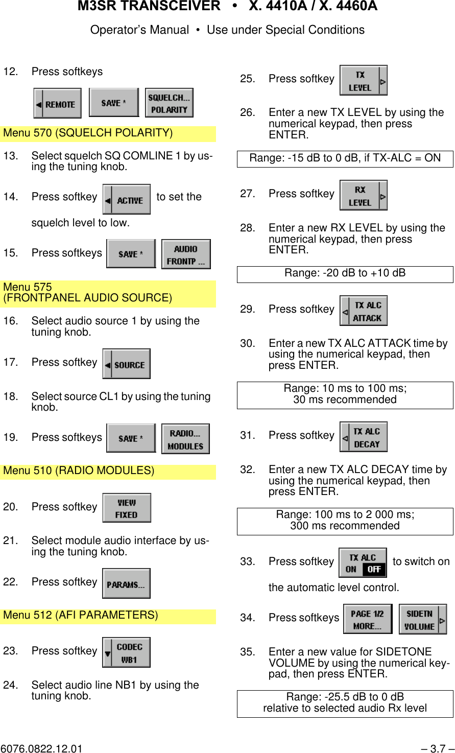
![065 75$16&(,9(5 ; $ ; $Operator’s Manual • Use under Special Conditions6076.0822.12.01 – 3.11 – :LGHEDQG'LJLWDOFor voice communication, narrowband audio line NB1 is used, carrier activation is performedvia keyline PTT_1L low-active. Modulation is in AM or FM (see chapter 3.3.1). In addition, adigital data terminal is connected. Data communication is carried out via wideband audio lineWB1 and carrier activation via keyline PTT_1 low-active. Modulation is in ASK (= amplitudeshift keying) or FSK (= frequency shift keying). 1RWH,QGLSKDVHPRGHVLJQDOVFDQEHWUDQVPLWWHGZLWKDGDWDUDWHRIXSWRNELWV3OHDVHREVHUYHWKHORZHUFXWRIIIUHTXHQF\RI+]%HORZWKLVIUHTXHQF\WKHGLJLWDO$0PRGXODWRUZLOOVZLWFKEDFNWRFDUULHUOHYHOCommunication Mode Comline Keylines Audio Lines External DeviceMappingPLL_1L PTT_1 PTT_2L PTT_2 NB1 WB1 NB2 WB2V/D UNCP CL1 x [WB DIGITAL BB CL1 [ [ 'LJLWDO0RGHPWB DIGITAL DP CL1 [ [DigitalData TerminalX26.1.2.3.4.6.7.8.910.11.12.13.18.20M3SR TransceiverAF Tx A NB AF Tx B NB AF Rx A NB AF Rx B NBAF Tx A WB AF Tx B WB AF Rx A WB AF Rx B WBPTT_1LAGC (LSB)AGC (MSB)SquelchPTT_1CarrierAudio System no squelch softkeyno mutingStarting point: Menu 040 (MAIN)1. Press softkey Menu 400 (RADIO MAINTENANCE)2. ENTER maintenance PIN by using the numerical keypad, then pressENTER.3. Press softkeys Menu 565 (DEVICE MAPPING)4. Select SYNC WB DATA by using the tuning knob.5. Press softkey 6. Select Comline 1 by using the tuning knob, then press ENTER.7. Press softkey](https://usermanual.wiki/Rohde-and-Schwarz-and-Co-KG/61020307.Revised-Manual/User-Guide-1012212-Page-125.png)
![065 75$16&(,9(5 ; $ ; $Operator’s Manual • Use under Special Conditions– 3.12 – 6076.0822.12.018. Press key (front panel).9. Press key again.10. ENTER maintenance PIN by using the numerical keypad, then pressENTER.11. Press softkeys Menu 560 (AUDIO MAPPING)12. Check if audio line WB1 is connected with Comline CL1. If necessary, con-nect.13. Press softkey Menu 550 (PTT COMLINE MAPPING)14. Check if keyline PTT_1 is connected with Comline CL1, if it is low-active and only effective in remote mode. If necessary, configure.15. Press softkey Menu 570 (SQUELCH POLARITY)16. Select squelch SQ COMLINE 1 by us-ing the tuning knob.17. Press softkey to set thesquelch level to low.18. Press softkeys Menu 510 (RADIO MODULES)19. Press softkey 20. Select module audio interface by us-ing the tuning knob.21. Press softkey Menu 512 (AFI PARAMETERS)22. Press softkey 23. Select audio line WB1 by using the tuning knob.24. Press softkey 25. Enter a new TX LEVEL by using the numerical keypad, then pressENTER.Range: -3 dB to +15.5 dBrelative to 1.4 Vpp1RWH$SSUR[LPDWLRQWRWKHGLJLWDOLQSXWOHYHOZLOOVXIILFH7KHVLJQDOZLOOEHGLJLWL]HGE\PHDQVRIDQLQWHUQDOFRPSDUDWRU26. Press softkey 27. Enter a new RX LEVEL by using the numerical keypad, then pressENTER.Range: -3 dB to +15.5 dBrelative to 1.4 Vpp28. Press softkey 29. Select module VU POWERAMPLIFIER by using the tuning knob.30. Press softkey Menu 516 (VU TX PARAMETERS)31. Press softkey 32. Enter a new modulation depth by us-ing the numerical keypad, then press ENTER.Range: 10% to 99%; 90% recommended0 dB = 1.4 Vpp into 600 Ω-3 dB = 1.0 Vpp into 600 Ω+15.5 dB = 8.0 Vpp into 600 Ω](https://usermanual.wiki/Rohde-and-Schwarz-and-Co-KG/61020307.Revised-Manual/User-Guide-1012212-Page-126.png)
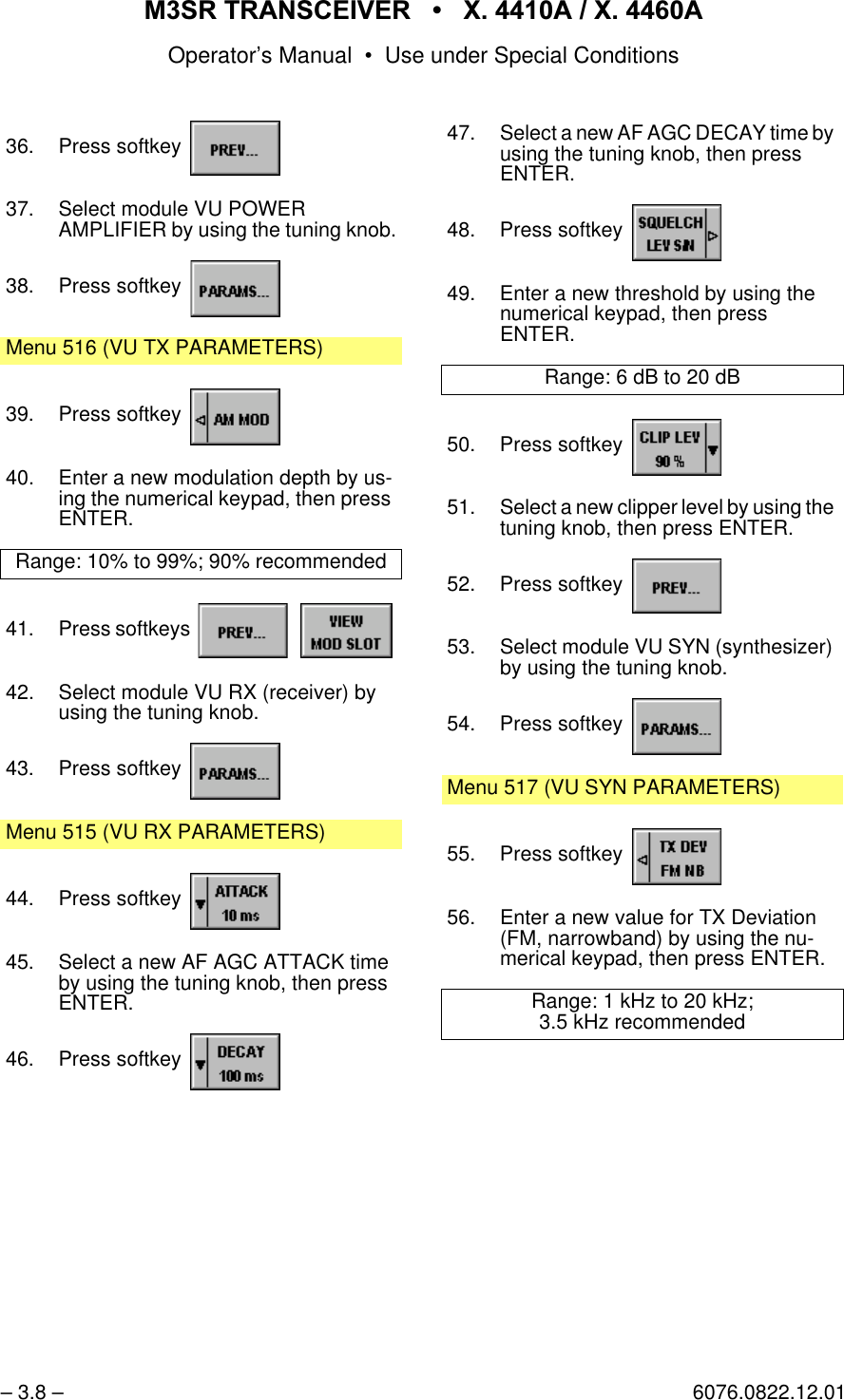
![065 75$16&(,9(5 ; $ ; $Operator’s Manual • Use under Special Conditions– 3.14 – 6076.0822.12.0113. Press softkey Menu 550 (PTT COMLINE MAPPING)14. Check if keyline PTT_2 is connected with Comline CL1, if it is high-active and only effective in remote mode. If necessary, configure.15. Press softkey Menu 510 (RADIO MODULES)16. Press softkey 17. Select module audio interface by us-ing the tuning knob.18. Press softkey Menu 512 (AFI PARAMETERS)19. Press softkey 20. Select audio line NB2 by using the tuning knob.21. Press softkey 22. Enter a new TX LEVEL by using the numerical keypad, then pressENTER.Range: 0 dB +3 dB23. Press softkey 24. Enter a new RX LEVEL by using the numerical keypad, then pressENTER.Range: 0 dB +3 dB (effective level into 600 Ω)1RWH:LWKD/LQNWHVWVLJQDORIN+]ZLWKN+]GHYLDWLRQWKHRXWSXWOHYHOZLOOEHDGMXVWDEOHWRG%G%P25. Press softkeys 26. Select module VU SYN (synthesizer) by using the tuning knob.27. Press softkey Menu 517 (VU SYN PARAMETERS)28. Press softkey 29. Enter a value of 20 kHz for TX Devia-tion for Link 11 operation by using the numerical keypad, then pressENTER.30. Press softkey 31. Enter a new value for fine tuning of synthesizer FM modulator by using the tuning knob, then press ENTER.1RWH)LQHWXQLQJIRUN+]GHYLDWLRQWHVWVLJQDON+]VLQXVRLGDOZLWKHIIHFWLYHOHYHORIG%PLQWRΩ](https://usermanual.wiki/Rohde-and-Schwarz-and-Co-KG/61020307.Revised-Manual/User-Guide-1012212-Page-128.png)
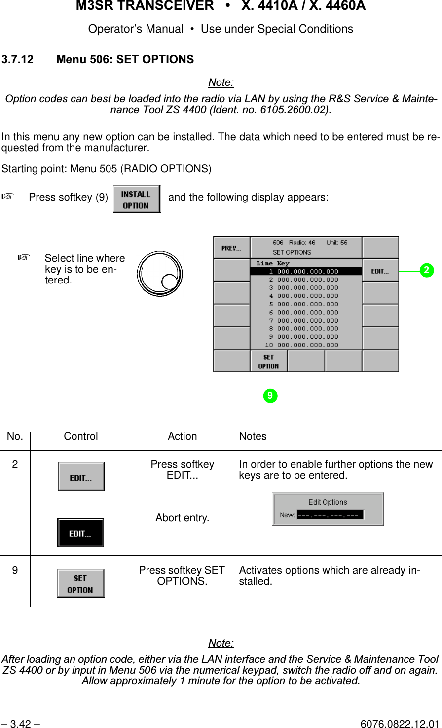
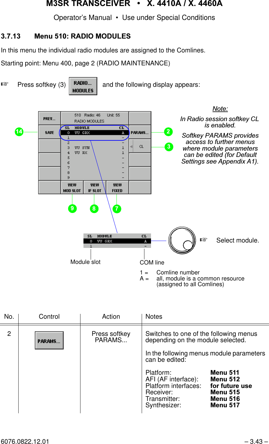
![065 75$16&(,9(5 ; $ ; $Operator’s Manual • Use under Special Conditions6076.0822.12.01 – 3.41 – 0HQX5$',2237,216In this menu all available radio options are listed.Starting point: Menu 400, page 2 (RADIO MAINTENANCE)+Press softkey (2) and the following display appears:1RWH7KH6126HULDO1XPEHURIWKHRSWLRQVFRQWUROOHULVWKHQXPEHU\RXQHHGWRVSHFLI\ZKHQRUGHULQJDQHZRSWLRQIURP5RKGH6FKZDU]<RXZLOOWKHQJHWD62&6RIWZDUH2SWLRQV&RQWUROOHUILOHWKDWFDQEHORDGHGE\XVLQJWKH6HUYLFH0DLQWHQDQFH7RROsoftkey OPTIONS...1RWH,Q5DGLRVHVVLRQVRIWNH\,167$//237,21LVHQDEOHGList of radio options whichare installed and can there-fore be activated0HQXSerial no. of options controller](https://usermanual.wiki/Rohde-and-Schwarz-and-Co-KG/61020307.Revised-Manual/User-Guide-1012212-Page-155.png)
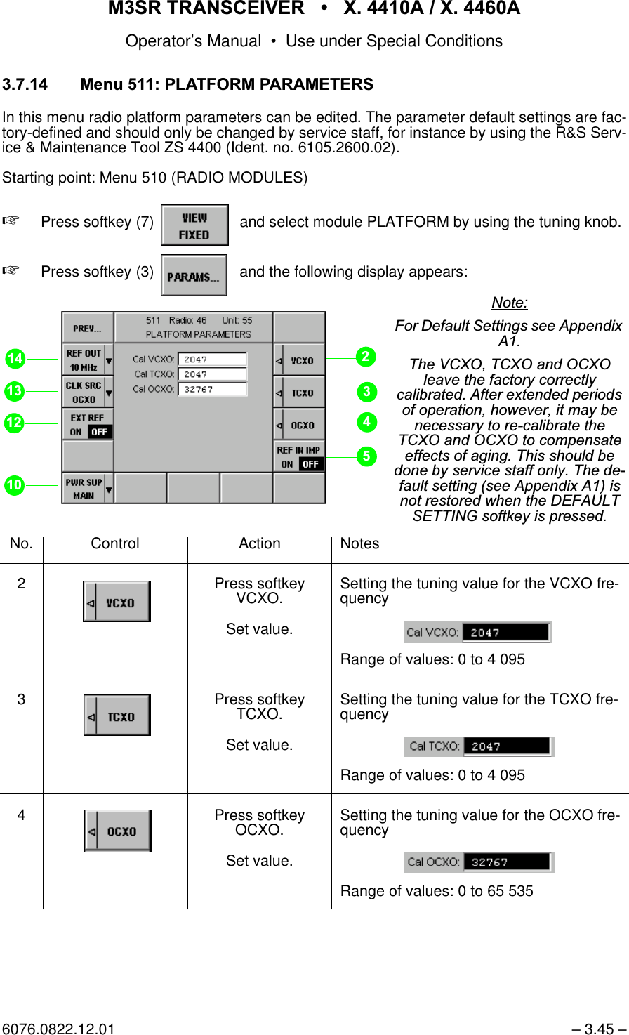
![065 75$16&(,9(5 ; $ ; $Operator’s Manual • Use under Special Conditions– 3.46 – 6076.0822.12.015 Press softkey REF IN IMP. Switches the input impedance of interface X10 (Reference Frequency):2)) input is high impedance2150-Ω input at X10 enabled10 Press softkey PWR SUP.Select setting.Selection of the input to be monitored (CBIT):0$,1selects X31%$77selects X320% selects both DC power inputs12 Press softkeyEXT REF. Switches monitoring function on or off.1RWH,IWKHLQSXWLVPRQLWRUHG 21WKHLQWHUQDO2&;2RU7&;2KDVWRV\QFKURQL]HWRWKHH[WHUQDOUHIHUHQFHVLJQDO,IWKLVIDLOVD&%,7PHVVDJHZLOOFRPHXS13 Press softkey CLK SRC.Select setting.Selection of the clock sourceOCXO is recommended.14 Press softkey REF OUT.Select setting.Selection of the clock frequency for refer-ence output X11No. Control Action Notes](https://usermanual.wiki/Rohde-and-Schwarz-and-Co-KG/61020307.Revised-Manual/User-Guide-1012212-Page-160.png)
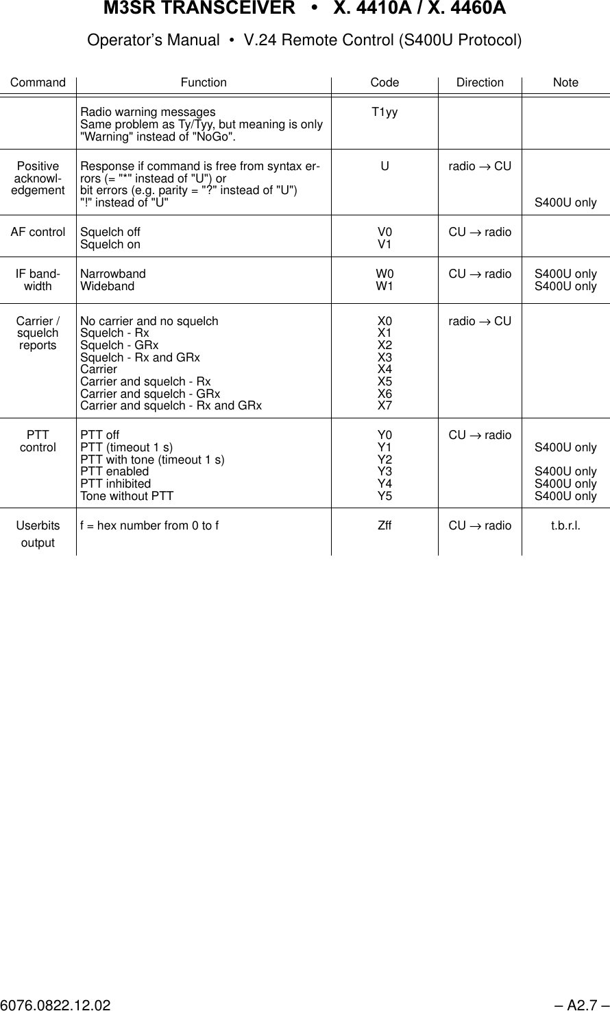
![065 75$16&(,9(5 ; $ ; $Operator’s Manual • V.24 Remote Control (S400U Protocol)6076.0822.12.02 – A2.5 –$ 5HPRWHFRQWURO&RGHVCommand Function Code Direction NoteEPM modes Plain (not encrypted)Cipher ext. (encrypted) B0B7 CU → radioPresets Preset (stored in remote CU)xx = 00 to 99e.g. no. 05: C005F305000L1C0xx CU → radio S400U onlyChannel loading Loading of frequencies into channelxx = 00 to 99 (= preset stored in radio) C6xxFxxxxxx[x] CU → radio S400U onlyOperation VoiceDataB0: wideband analogLink 11Link 4aB0: wideband digital basebandB0: wideband digital diphaseD0D1D1D4D5D6D7CU → radio S400U onlyS4400 onlyt.b.r.l.Local mode Operation via local CU(E instead of U at the end of message)All commands and inquiries are answered with "axxE" only.E radio → CUS4400 onlyFrequencyVHF + UHF100.000 to 511.975 MHz(25-kHz spacing)100.000.0 to 511.991.6 MHz(8.33-kHz spacing)VHF100.000 to 162.975 MHz(25-kHz spacing)100.000.0 to 162.991.6 MHz(8.33-kHz spacing)UHF225.000 to 399.975 MHz(25-kHz spacing)225.000.0 to 399.991.6 MHz(8.33-kHz spacing)Fxxxxxx[x] CU → radiosee A2.11S4400 onlyS400U onlyS400U onlyGuard receiver OffOn G0G1 CU → radioClass of emission AMFM I1I7 CU → radioChannel Select channel (= preset stored in radio)xx = 00 to 99 Kxx CU → radioFrequencymodes Manuale.g. FxxxxxxL0Presete.g. C0xxFxxxxxxL1 (= preset stored in CU)e.g. KxxL1 (= preset stored in radio)e.g. QxxxxL1Guard (includes voice "B0D0" with AM "I1")e.g. F243000L2 (UHF guard frequency)Maritime (e.g. KxxL3)L0L1L2L3CU → radioS400U onlyS400U onlyn/a](https://usermanual.wiki/Rohde-and-Schwarz-and-Co-KG/61020307.Revised-Manual/User-Guide-1012212-Page-279.png)
![065 75$16&(,9(5 ; $ ; $Operator’s Manual • V.24 Remote Control (S400U Protocol)– A2.6 – 6076.0822.12.02Inquiry Carrier and squelch reportsrecommended time-out for inquiry "N" 1.2 s, for all other inquiries and commands 5 s (9 600 Bd)N CU → radioInquiries Version and date of radio software(response Vx.xxdd.mm.yy)Test message(response T0 to Txx)Channel or frequency(response Kxx or Fxxxxx)Entire setting parameters(response Pxyz[Cxxx*][Fxxxxxx][Kxx]Lx[Qxxyy*]BxDxGxIxSxVx[Wx**]Status of HDX setup[ ] = available according to selected mode* = S400U only** = valid in anti-jam mode onlyO0O1O2O3O5CU → radio S400U onlyS400U onlyRadio types Frequency rangex=1: VHFX=2: UHFX=3: VHF/UHFX=5 to 7Equipment typey=1 to 4y=5: Rxy=6: Txy=7: Rx/Txy=8: split sitePxyz radio → CUS400U onlyS400U onlyScanning Scanning between channels xx and yyxx = 00 to 98yy = 01 to 99Switched off by frequency (FxxxxxxL0) or channel (KxxL1) commandQxxyy CU → radio S400U onlyRadiomodes Radio offRadio on (low power)Radio on (medium power)Radio on (high power)S0S1S3S5CU → radio S4400: S0 is effective for Tx onlyTestmessages(CBIT)Radio GoRadio NoGo in local operationHighamp NoGoAmp NoGoVSWR > 2Carrier NoGoBlower onSupply voltage out of rangeLocal CU NoGoTx/Rx switch NoGoPP NoGoDC NoGoAC NoGoIF NoGoSynth NoGoOption 2 NoGoGRx NoGoLink 11 / 4A NoGoOption 1 NoGoRF NoGoOvertemperatureAudio IF NoGoFPGA NoGoBattery lowDAMA NoGoT0T1T2T3T4T5T6T7T8T9T10T40T41T42T43T44T45T46T47T48T49T50T51T52T53radio → CUS400U onlyS400U onlyS400U onlyS400U onlyS4400 onlyS4400 onlyS4400 onlyt.b.r.l.Command Function Code Direction Note](https://usermanual.wiki/Rohde-and-Schwarz-and-Co-KG/61020307.Revised-Manual/User-Guide-1012212-Page-280.png)
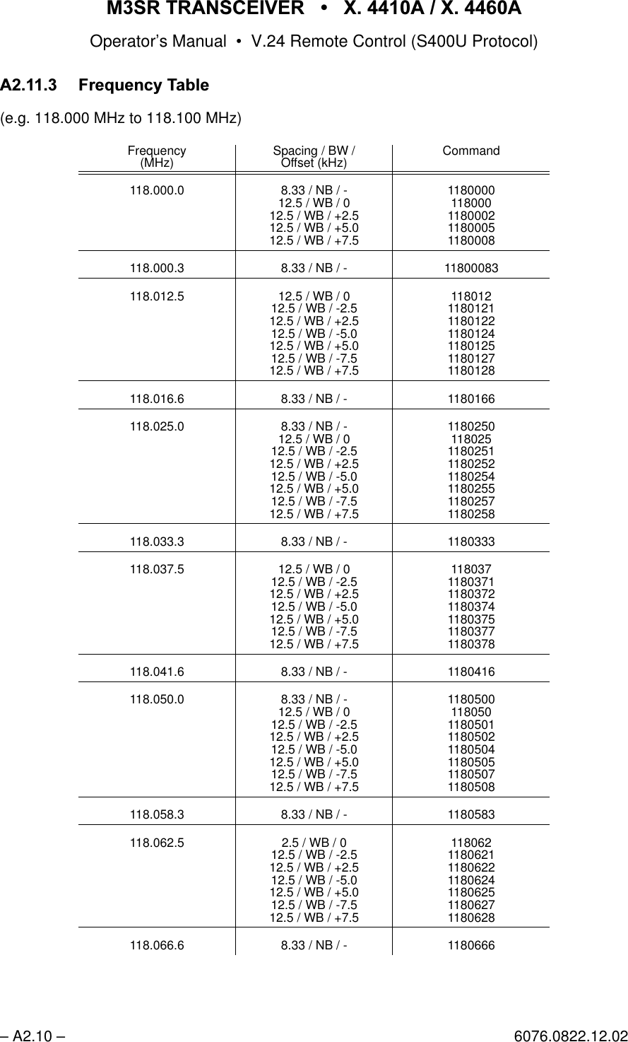
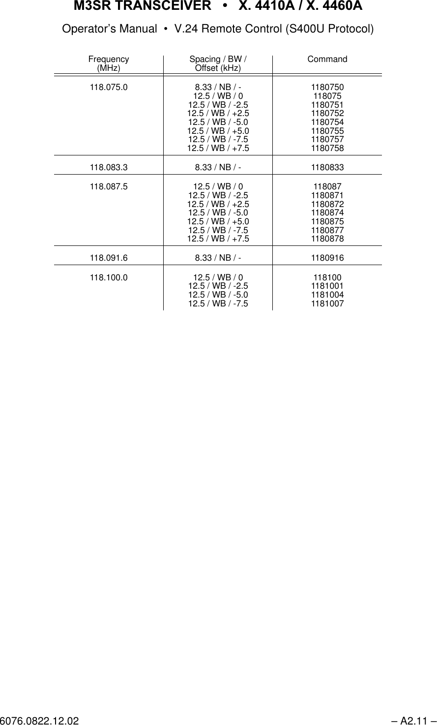
![065 75$16&(,9(5 ; $ ; $Operator’s Manual • V.24 Remote Control (S400U Protocol)6076.0822.12.02 – A2.9 –$ 5XOHVIRU5HPRWH)UHTXHQF\&RQWURORI6HULHV065$ ,QSXWRI'LJLWVN+]6SDFLQJZLWKRXW2IIVHWFormat: FFFFXX (XX = 00 / 12 / 25 / 37 / 50 / 62 / 75 / 87)$,QSXWRI'LJLWVN+]6SDFLQJZLWK2IIVHWRUN+]6SDFLQJa) OffsetFormat: FFFFXXO (XX = 00 / 12 / 25 / 37 / 50 / 62 / 75 / 87)O = 1: -2.5 kHzO = 2: +2.5 kHzO = 4: -5 kHzO = 5: +5 kHzO = 7: -7.5 kHzO = 8: +7.5 kHzb) 8.33-kHz spacingFormat: FFFFXXX (XXX = 000 / 083 / 166 / 250 / 333 / 416 / 500 / 583 / 666 /750 / 833 / 916)](https://usermanual.wiki/Rohde-and-Schwarz-and-Co-KG/61020307.Revised-Manual/User-Guide-1012212-Page-283.png)