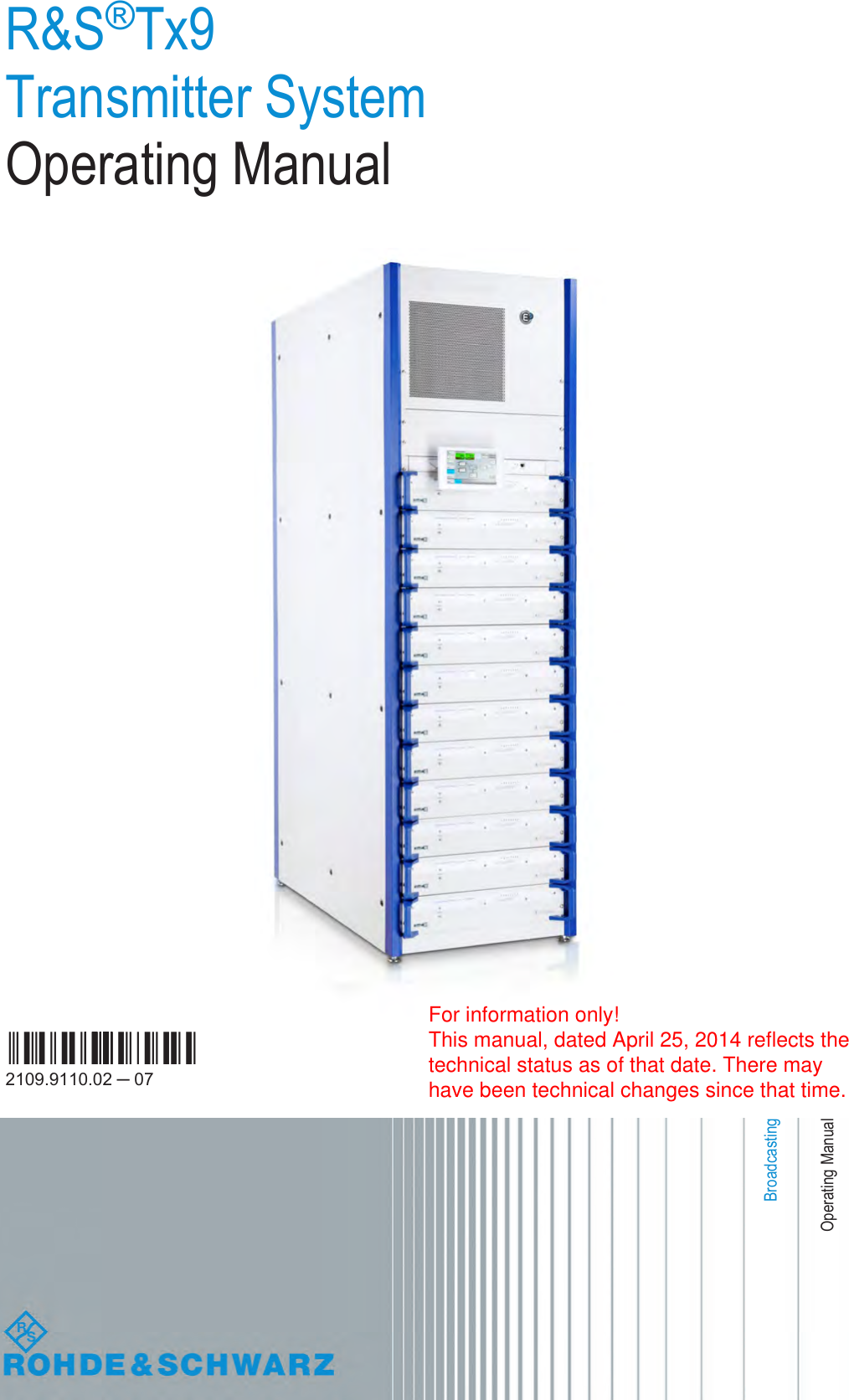
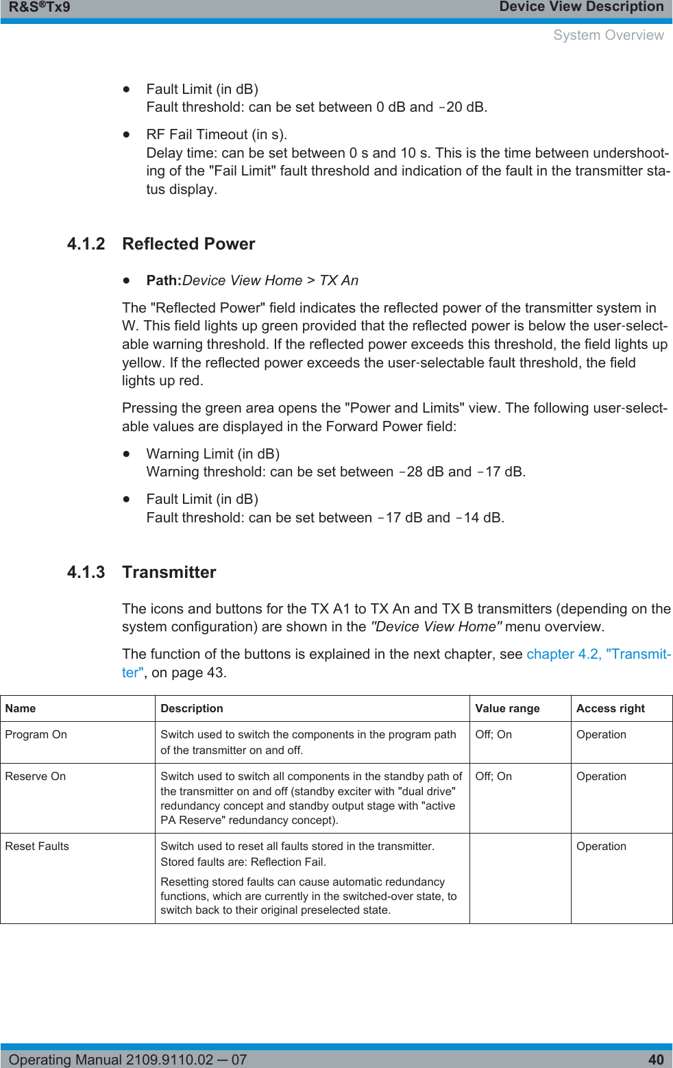
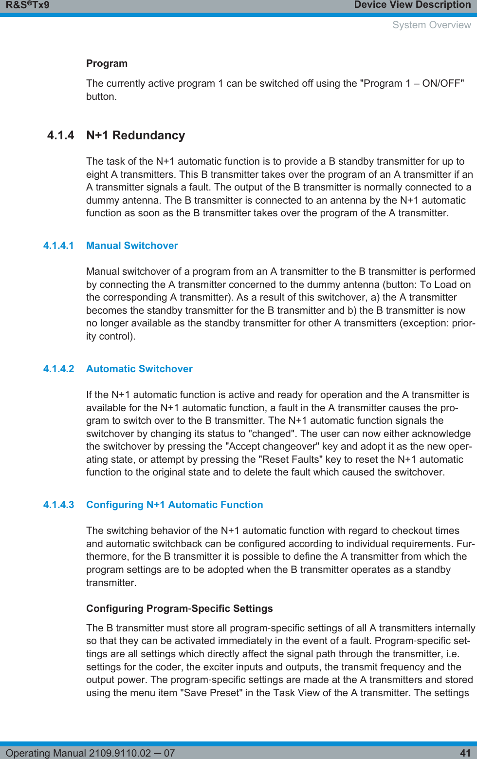
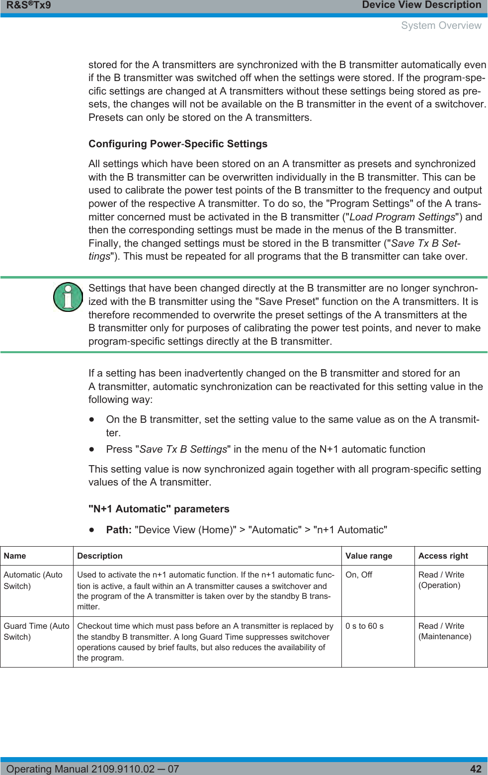
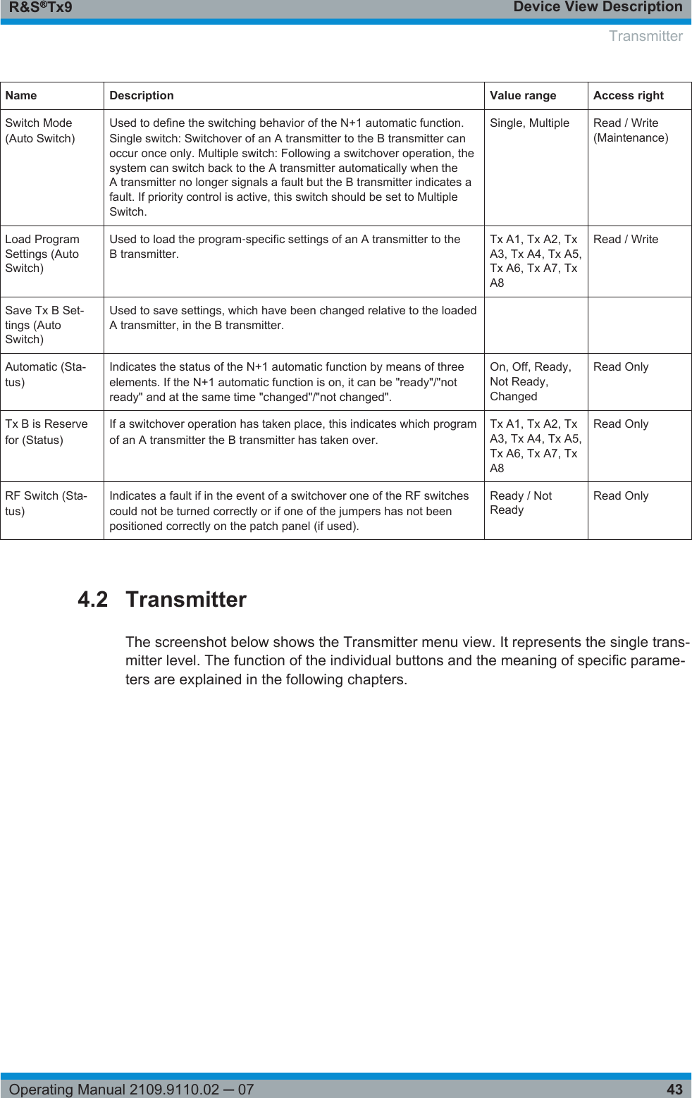
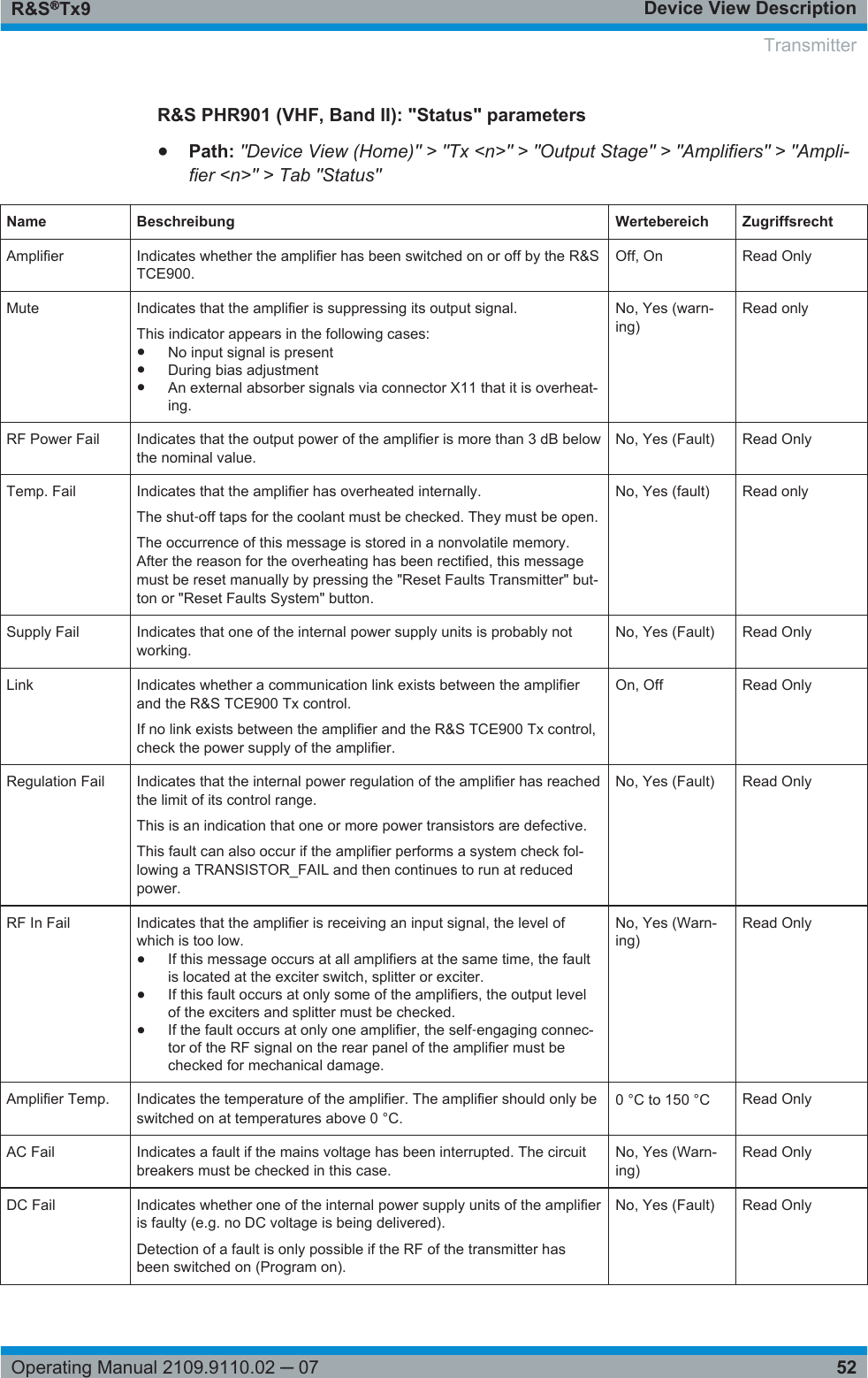
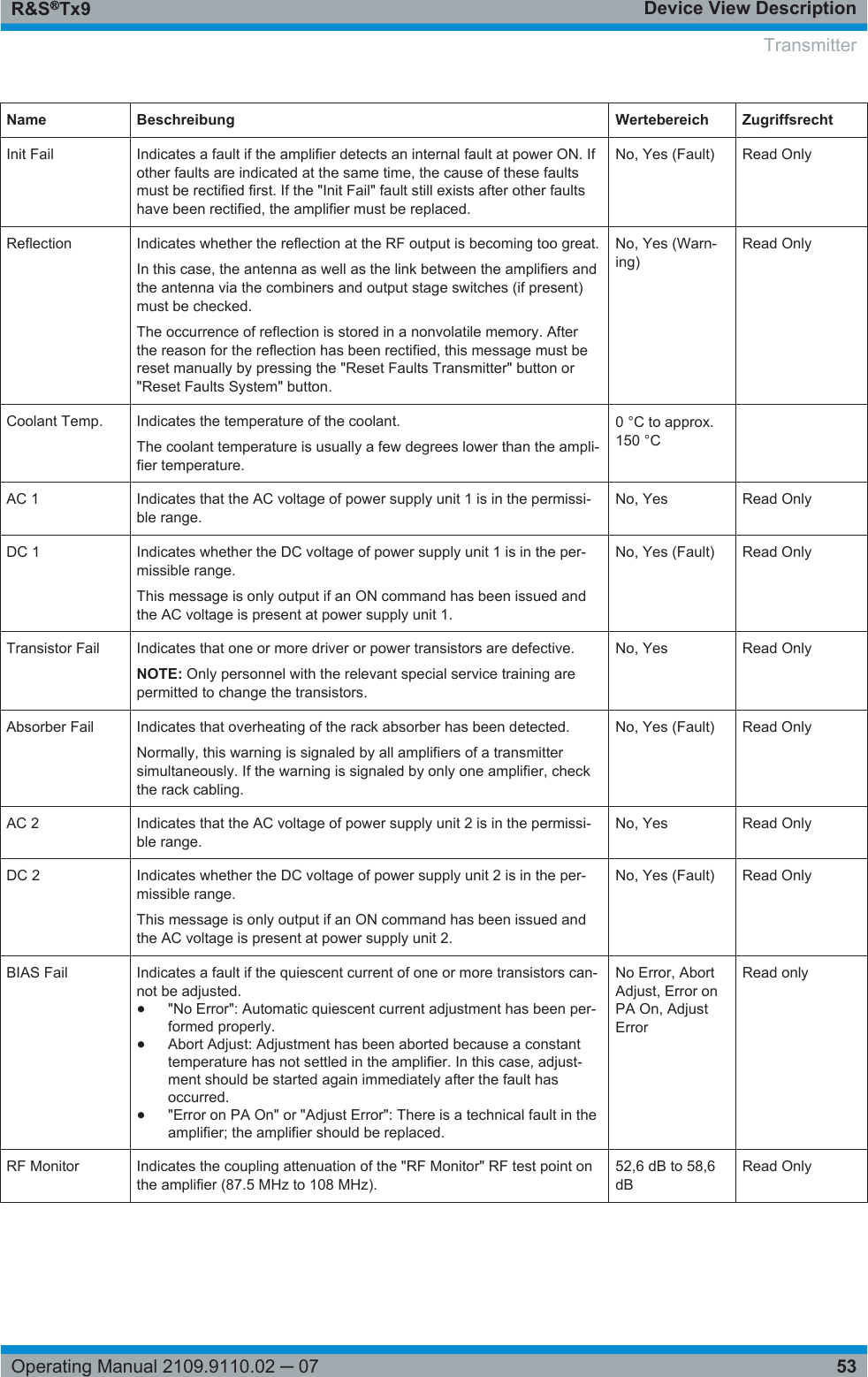
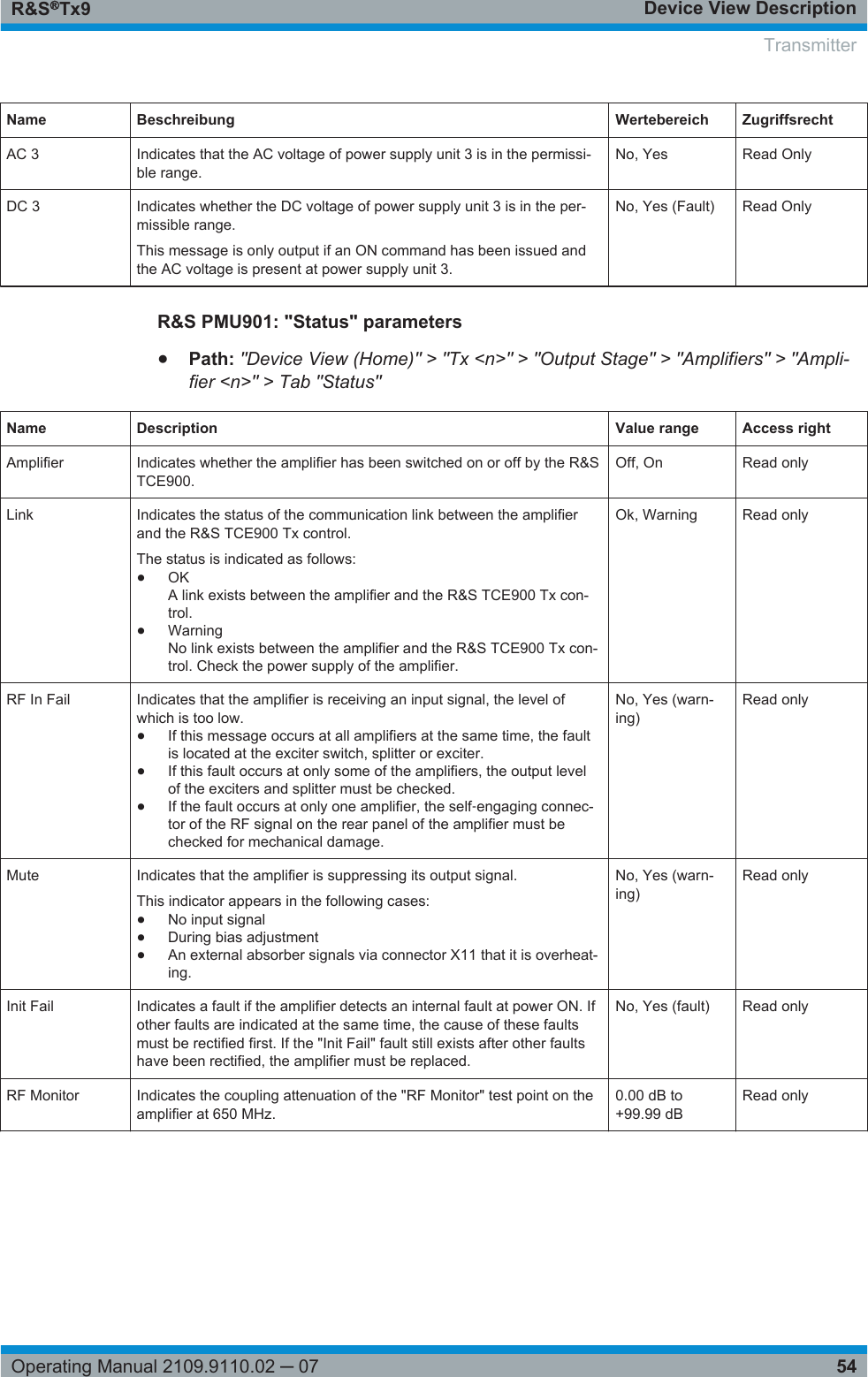
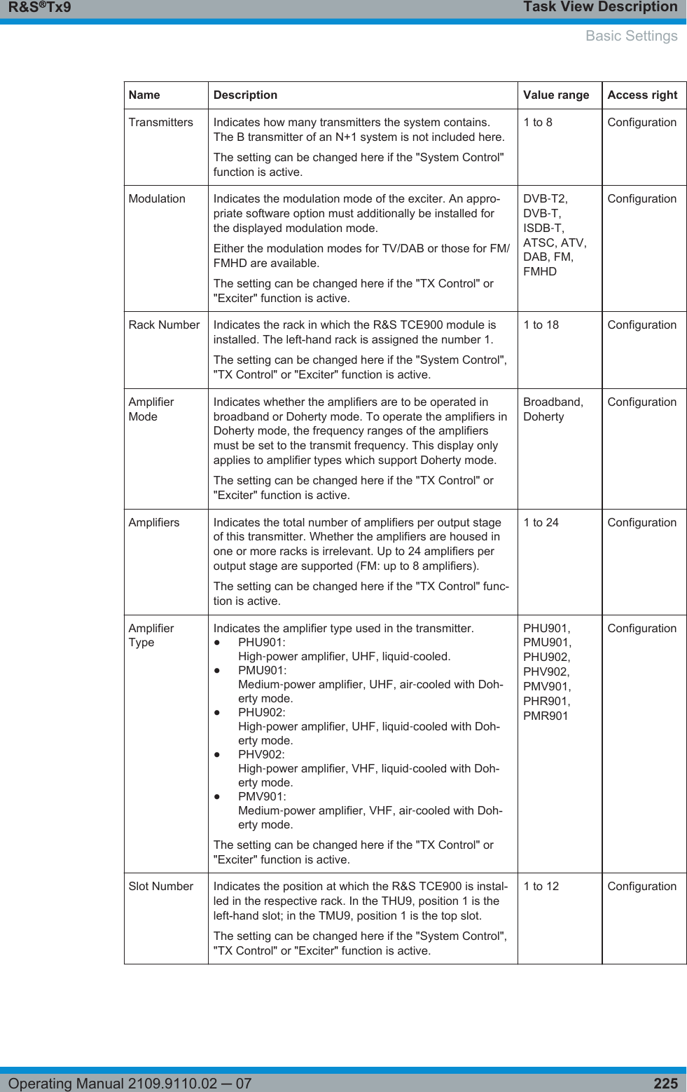
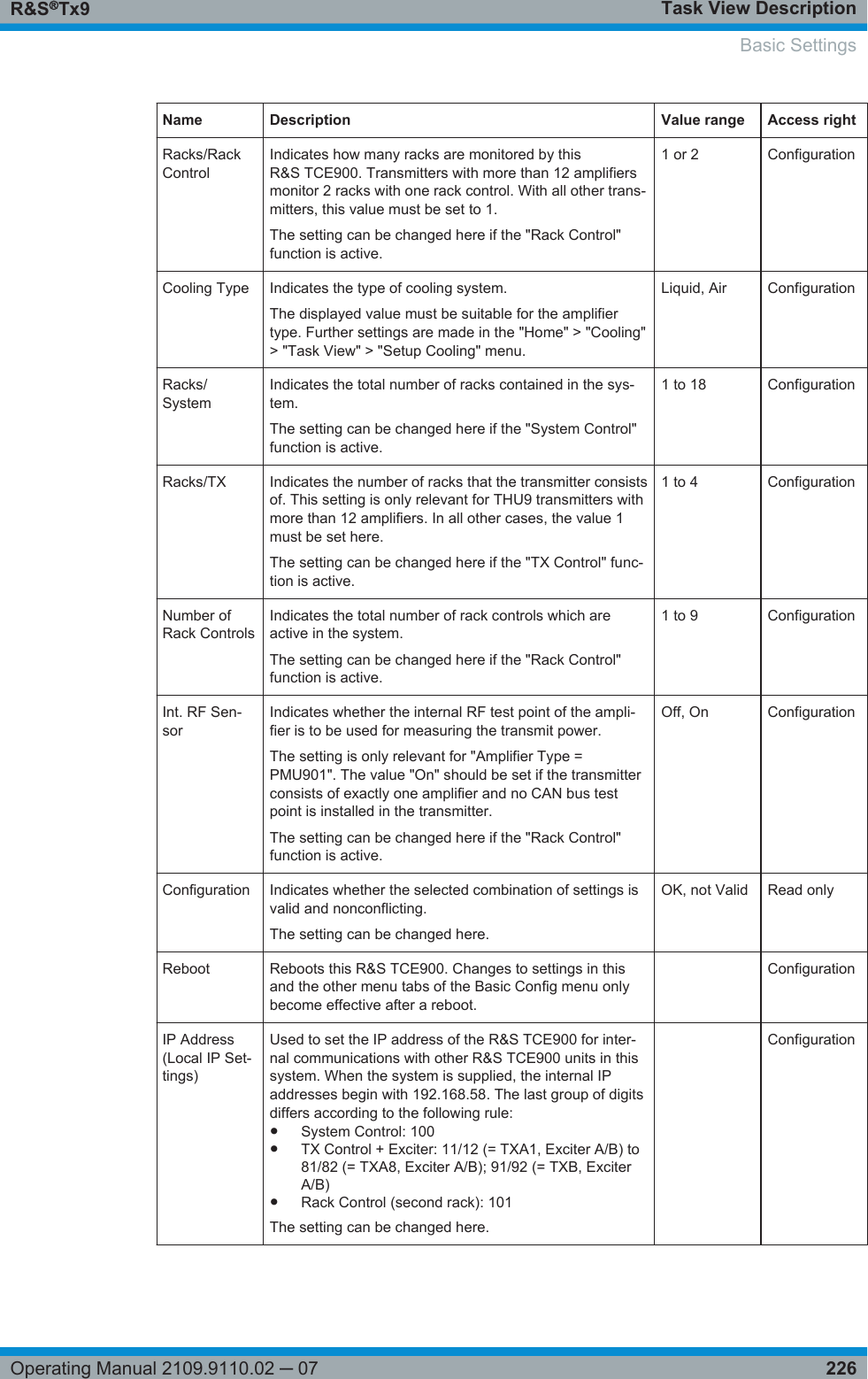
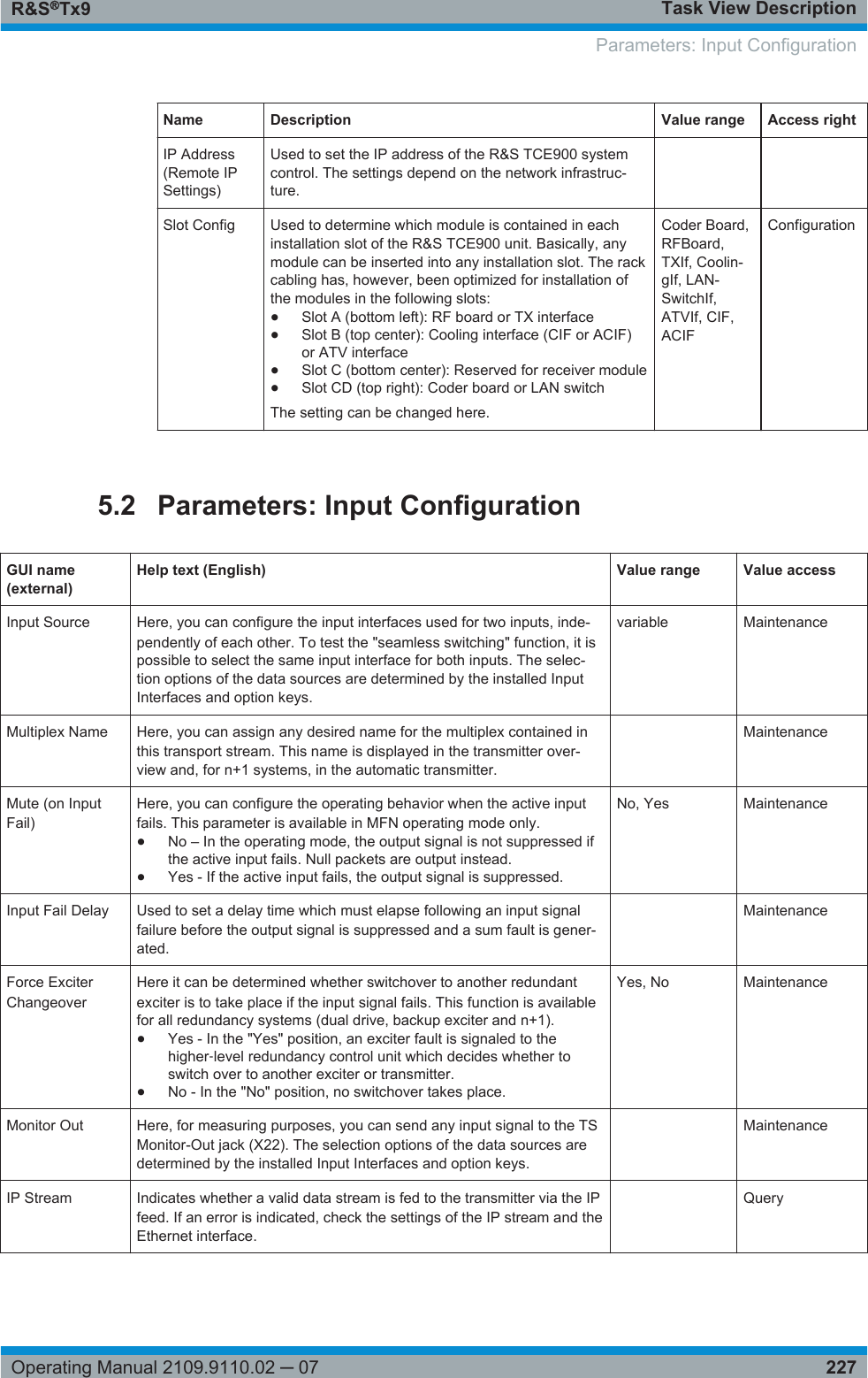
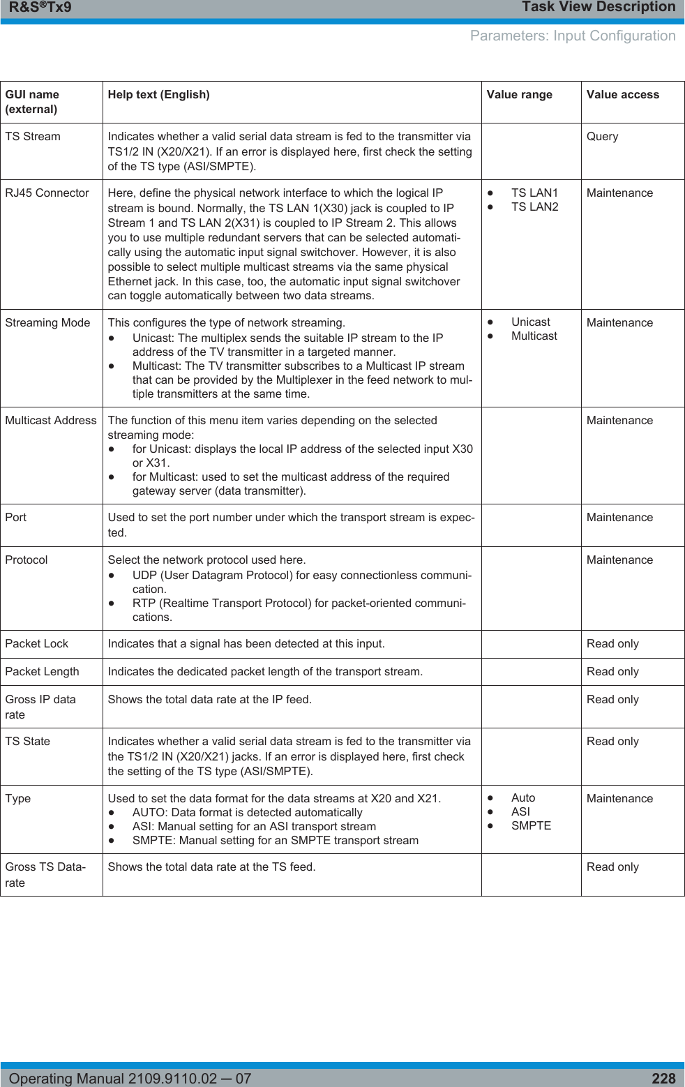
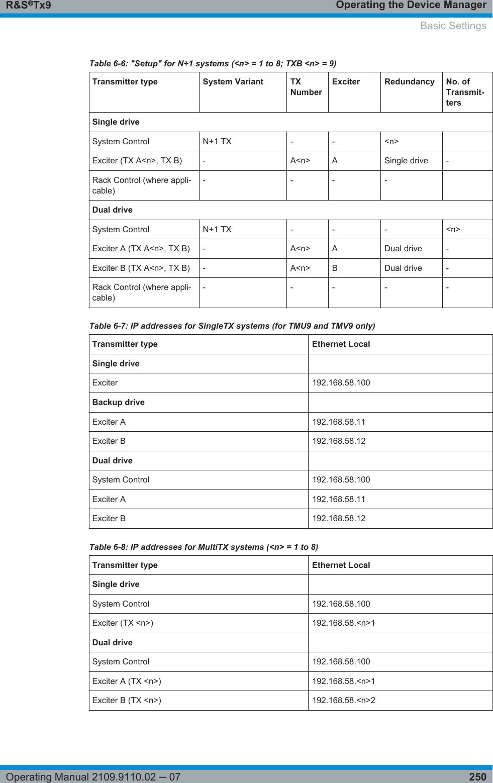
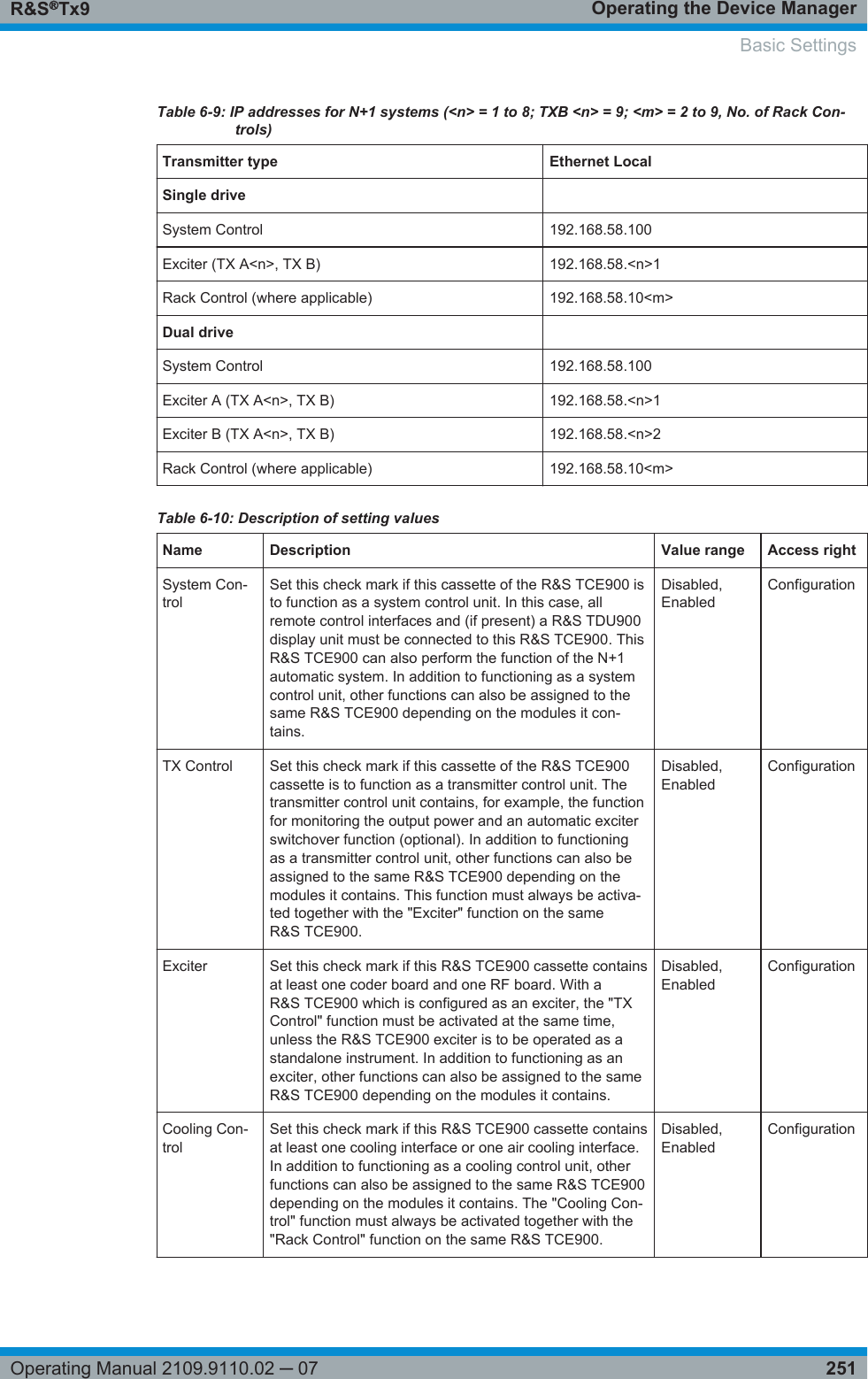
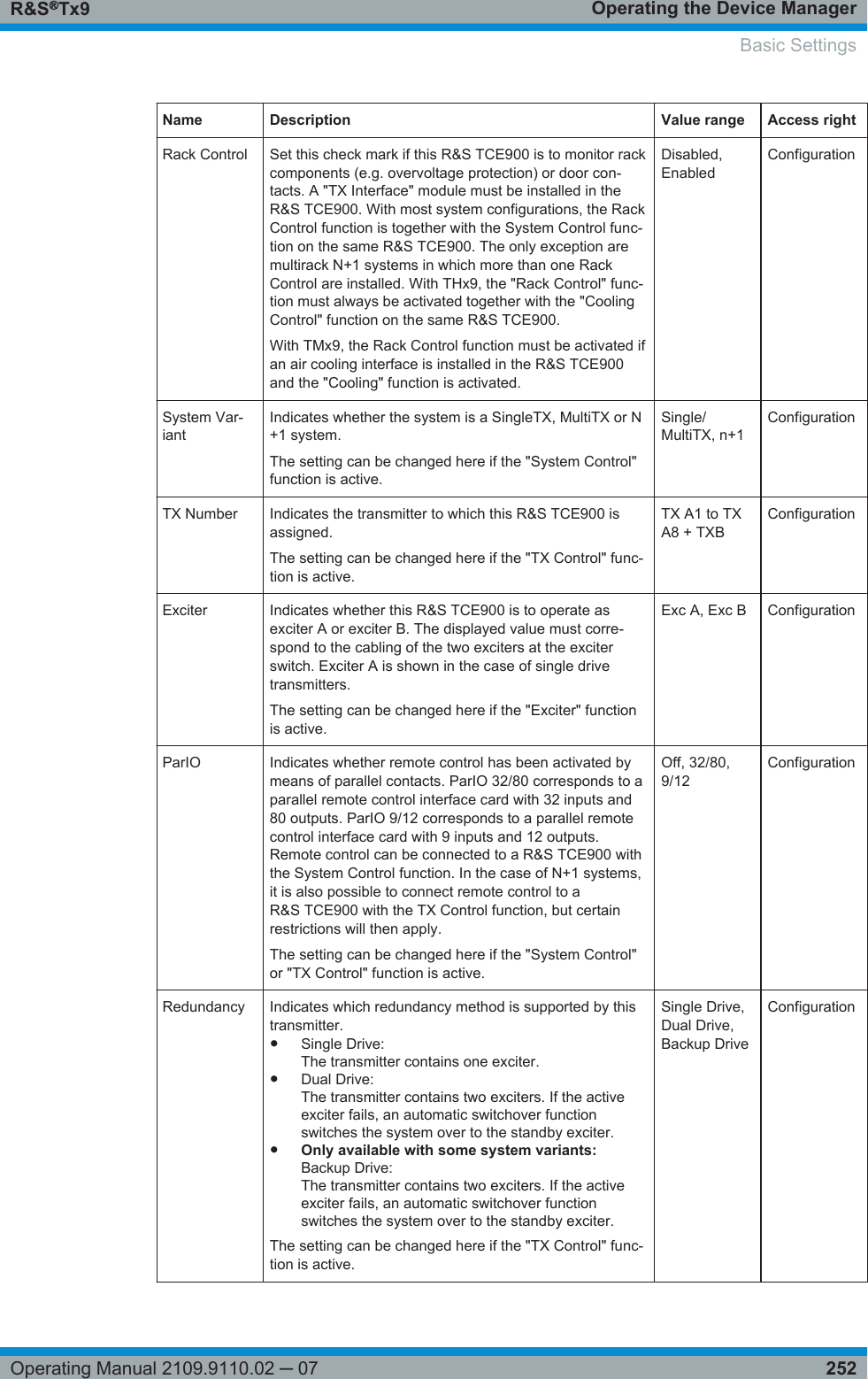
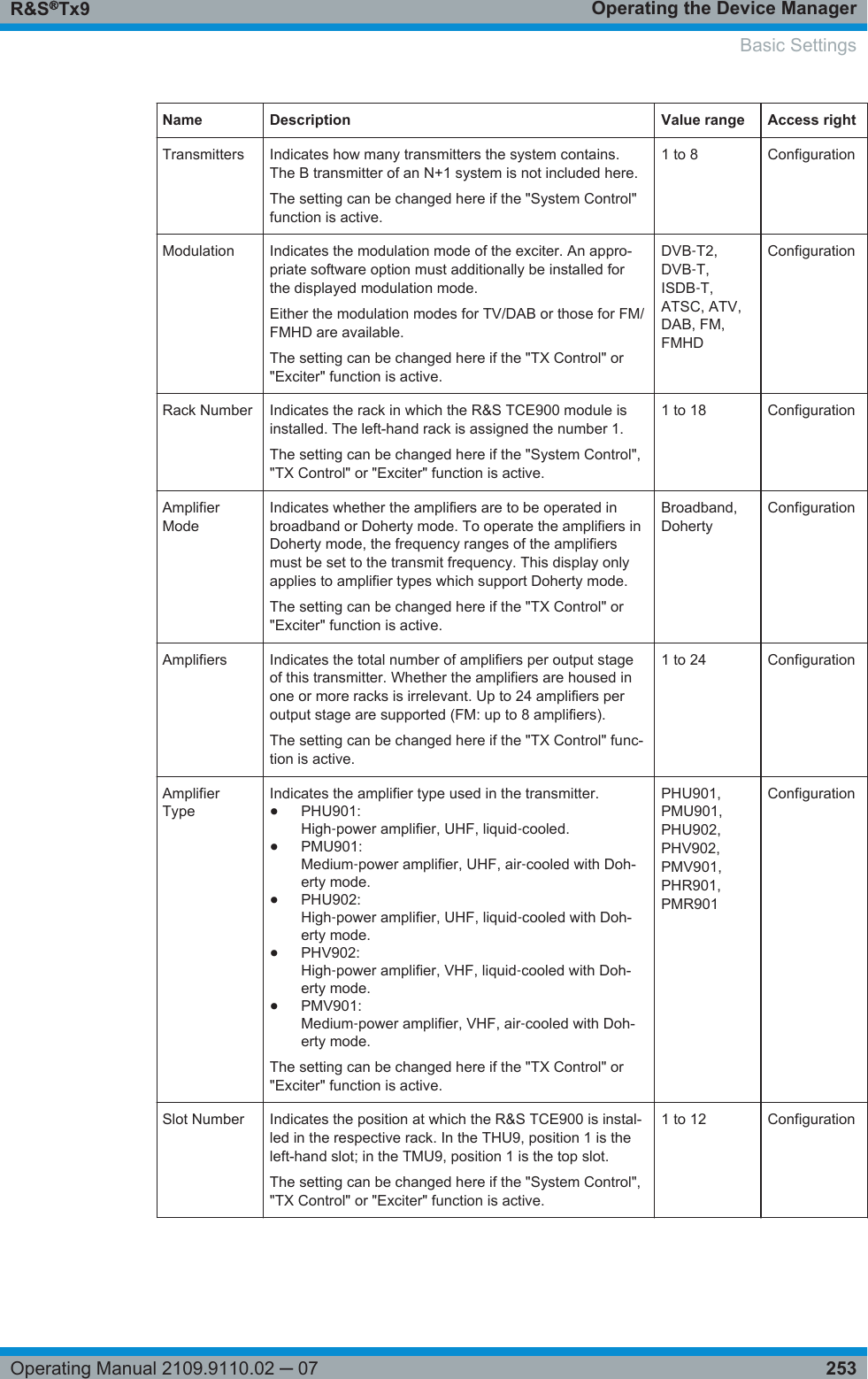
Rohde and Schwarz TMU91 500 Watt UHF ATSC Transmitter User Manual Setup Manual
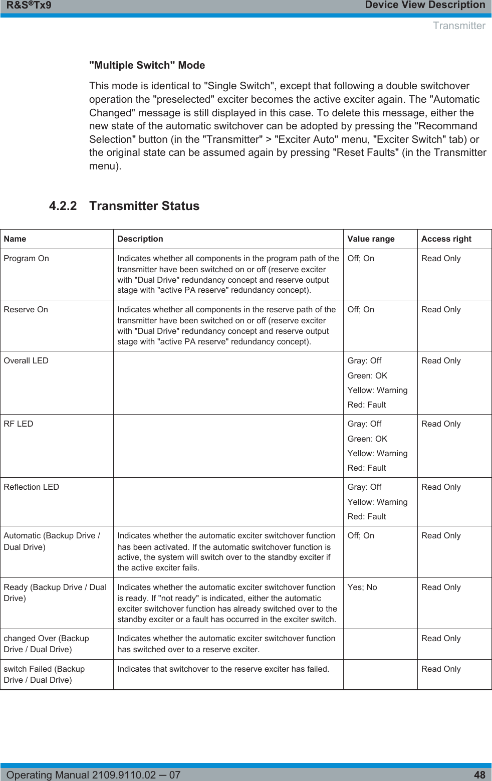
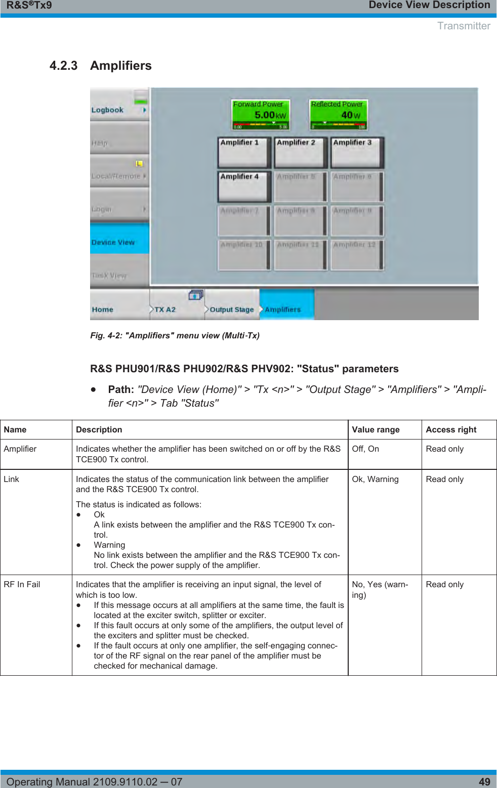
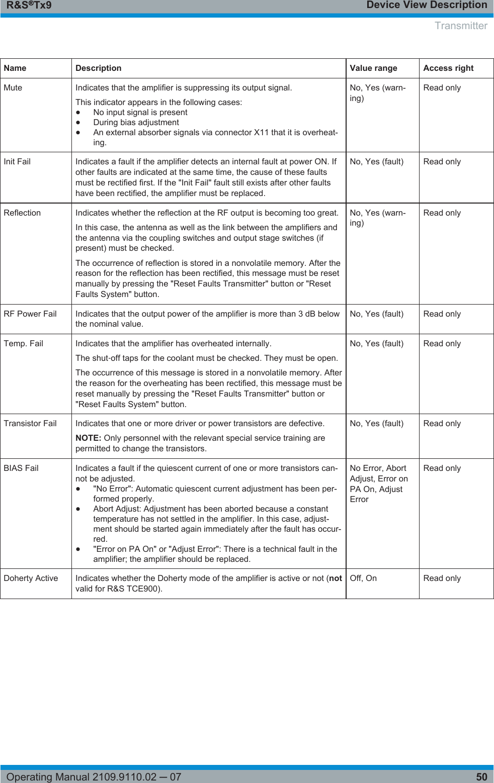
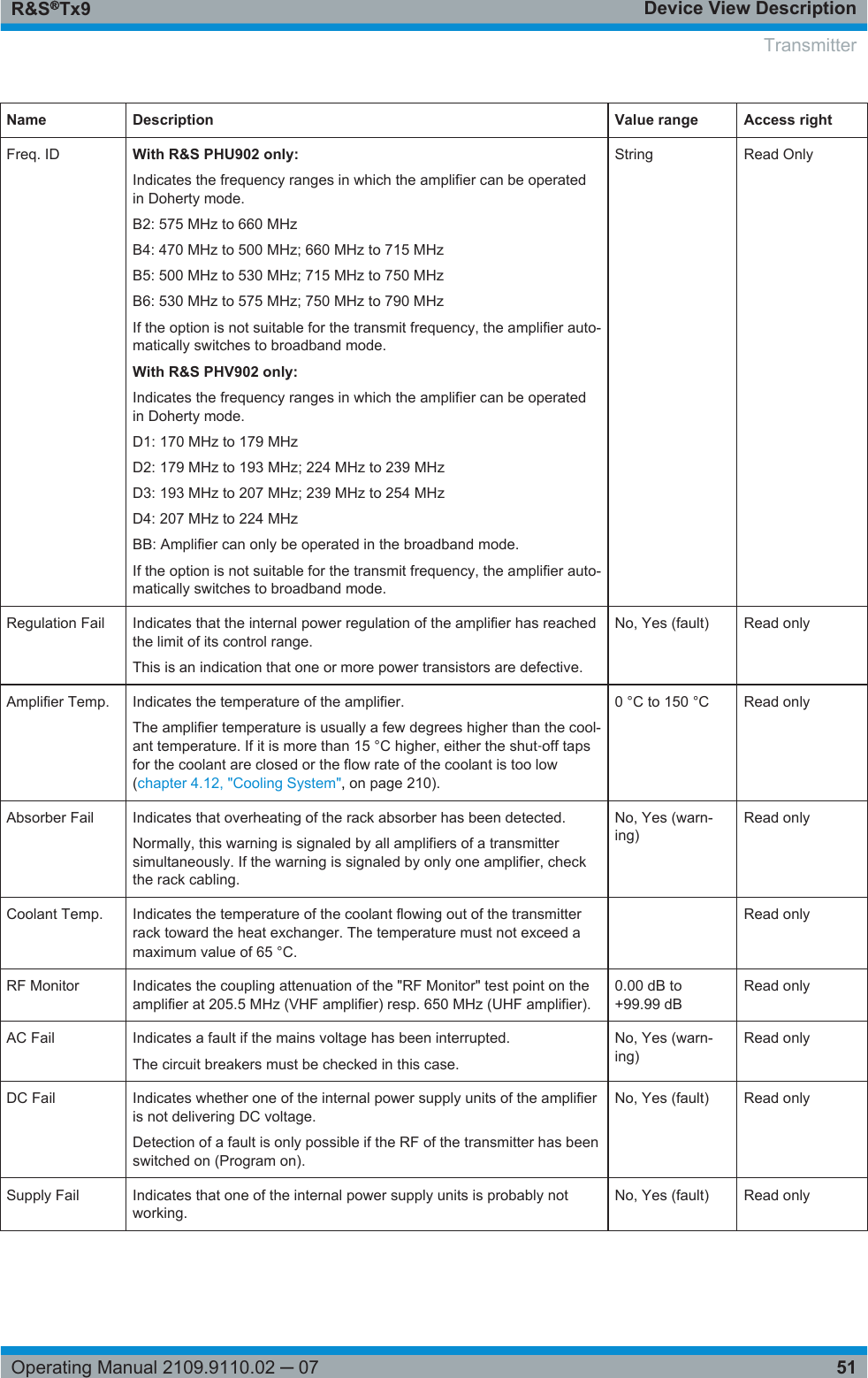
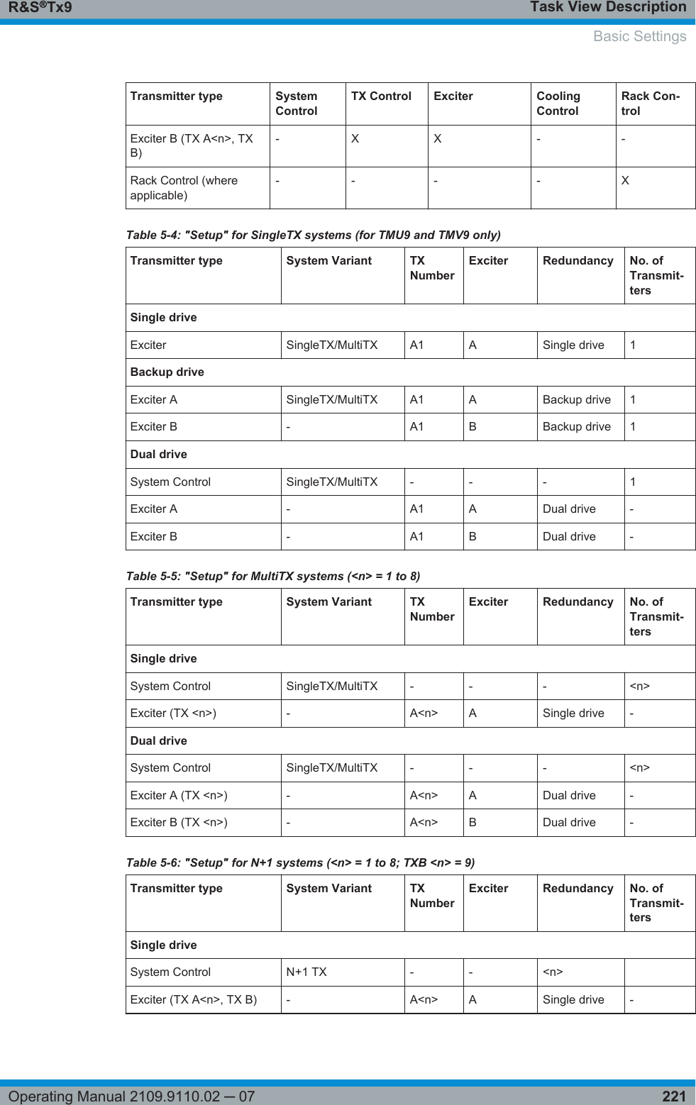
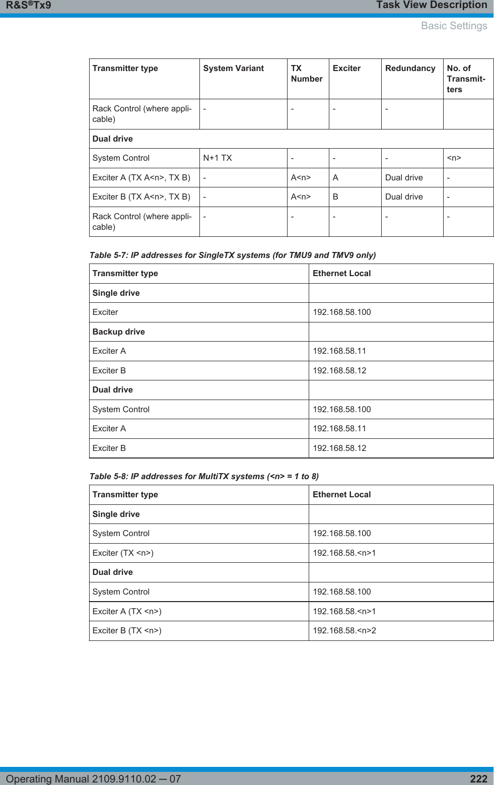
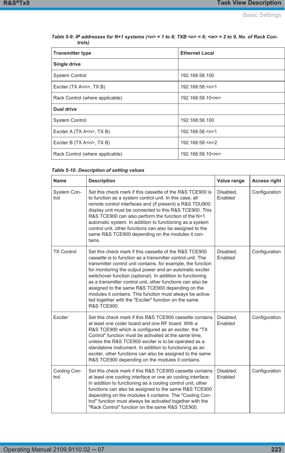
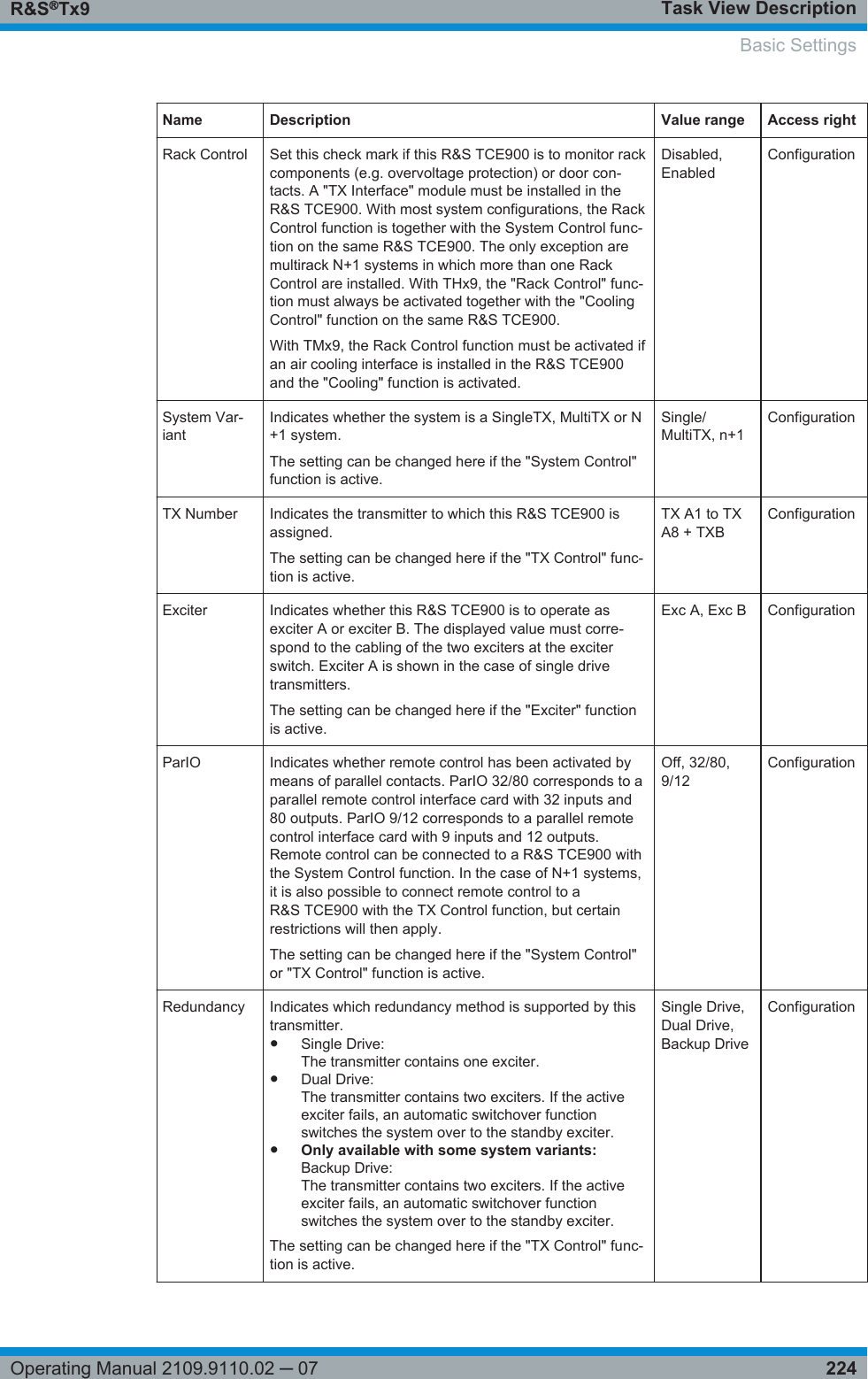
Rohde & Schwarz Inc 500 Watt UHF ATSC Transmitter Setup Manual
UserManual.wiki
>
Rohde and Schwarz
>
TMU91 User Manual
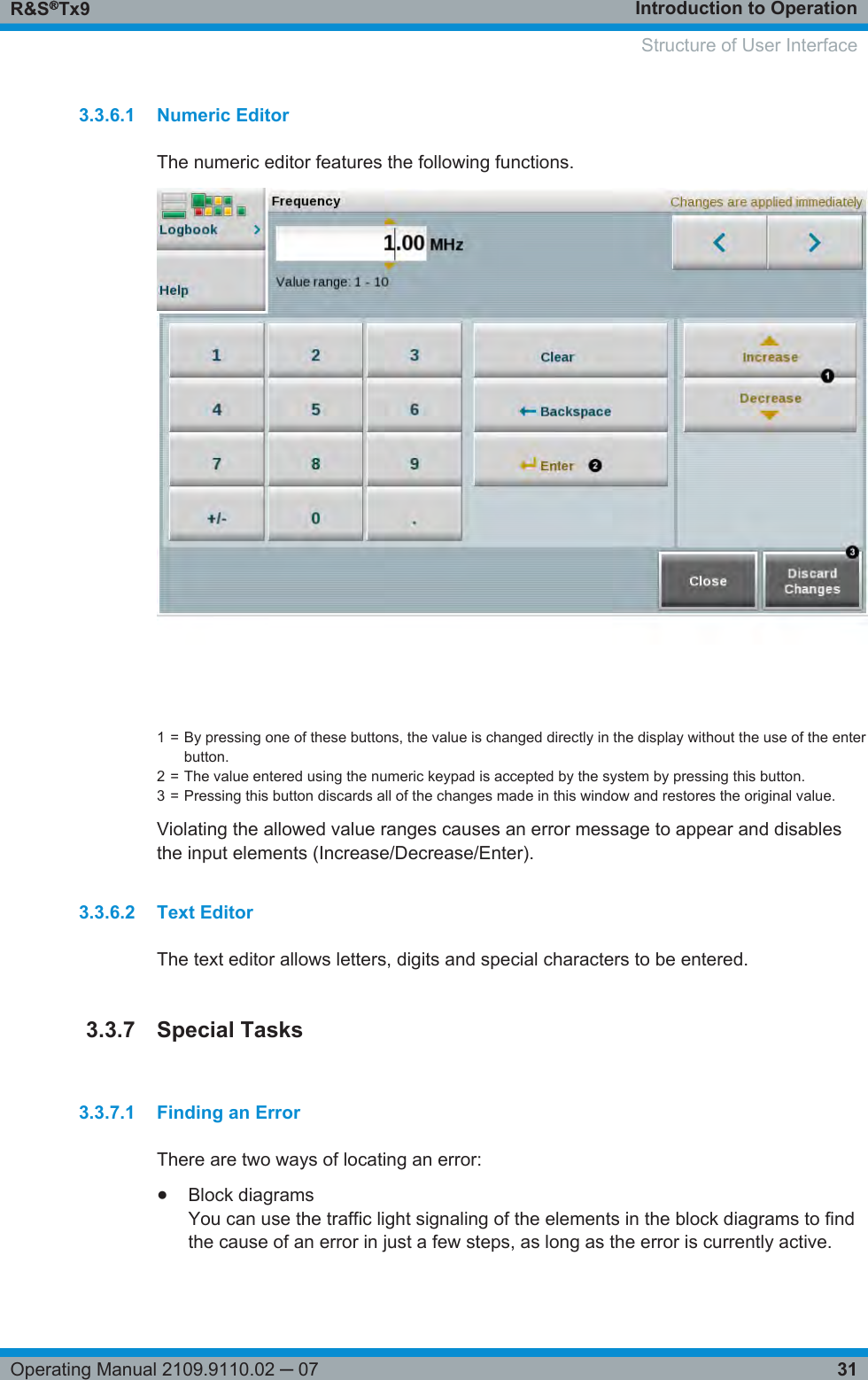
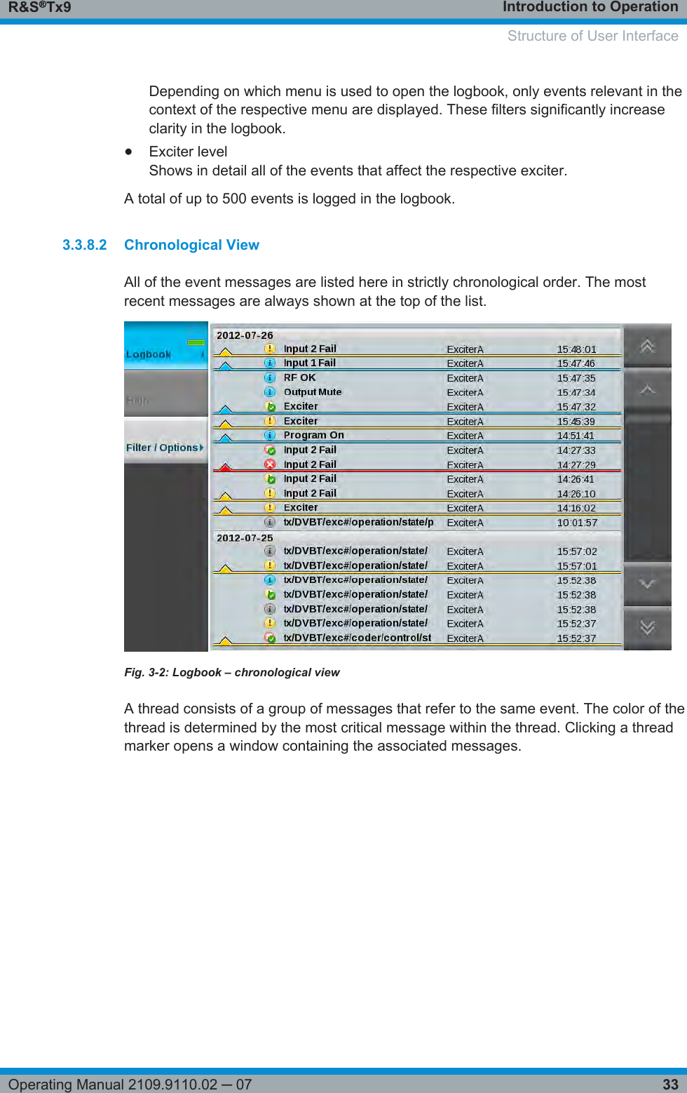
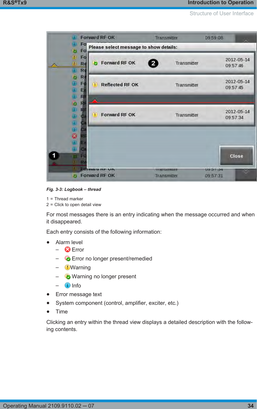
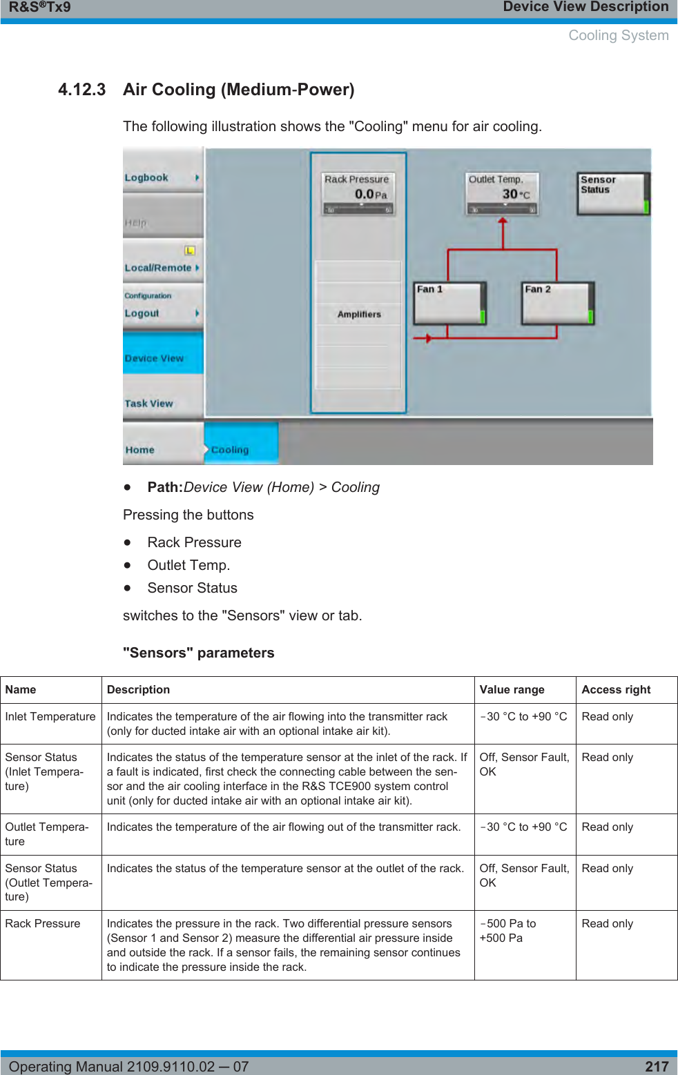
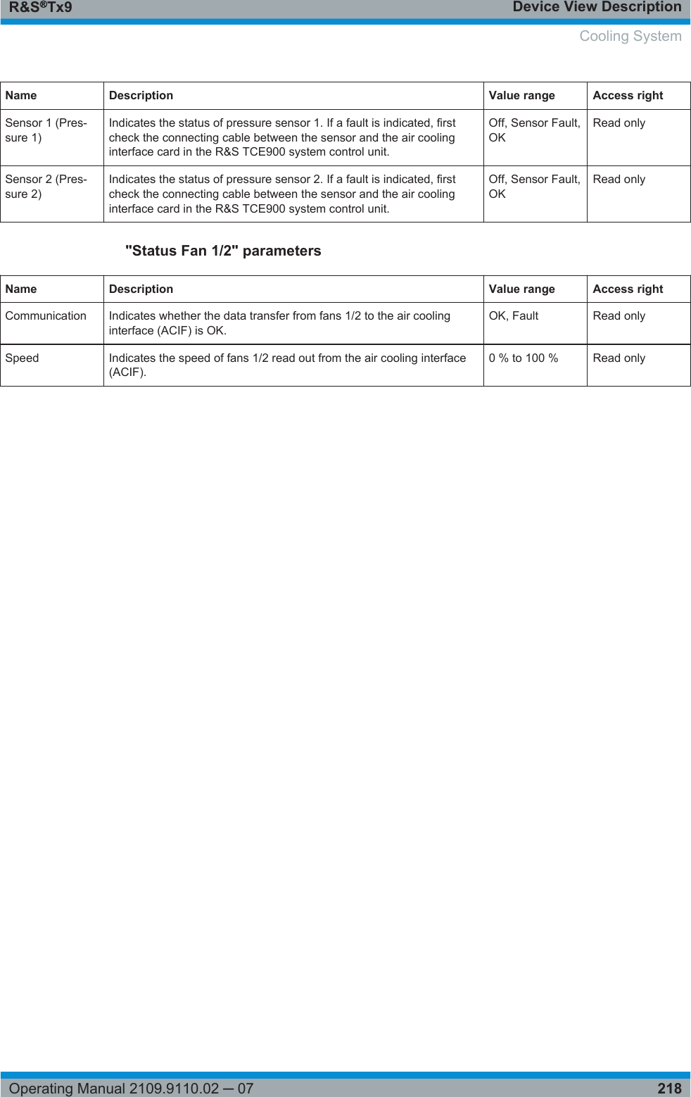
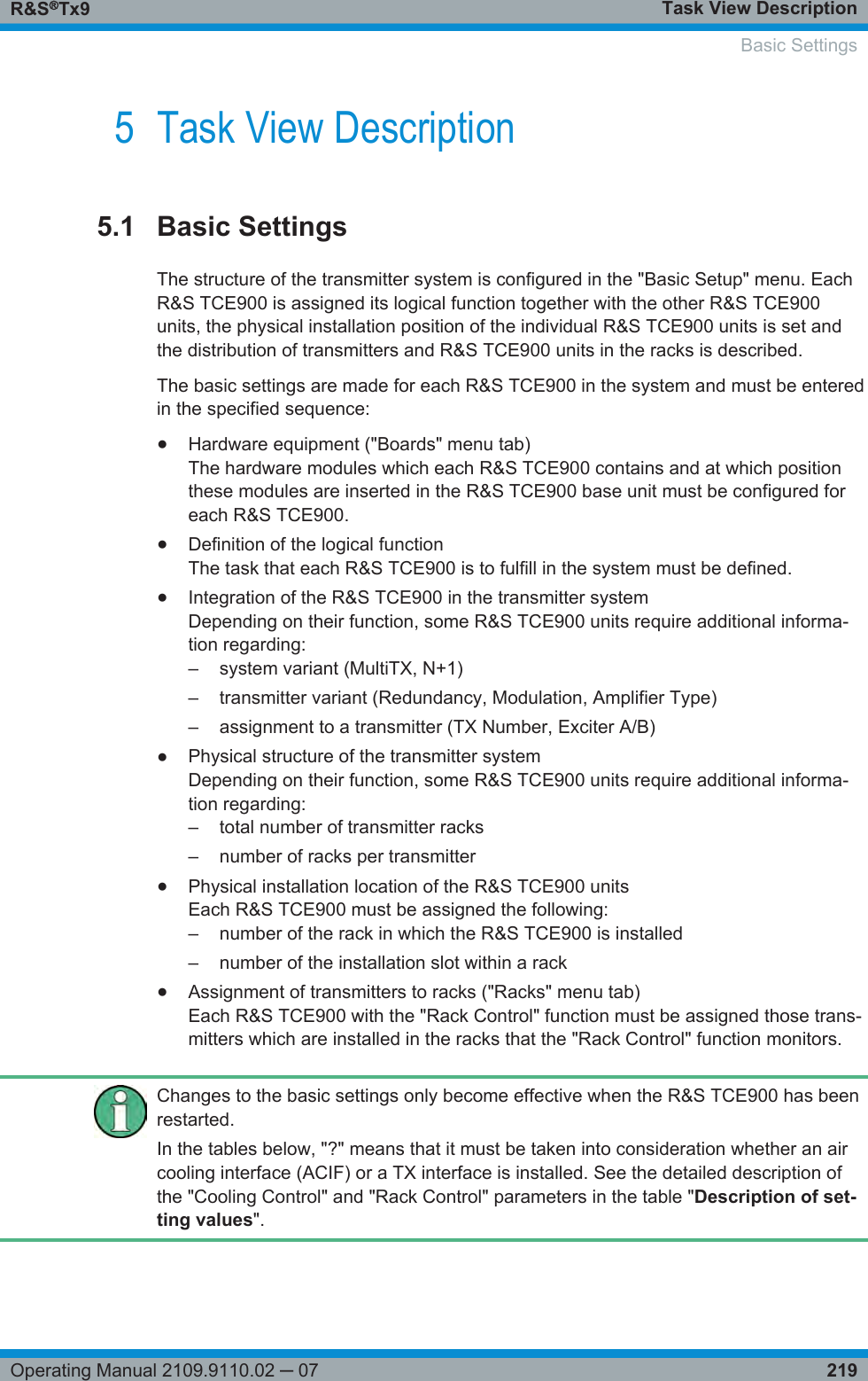
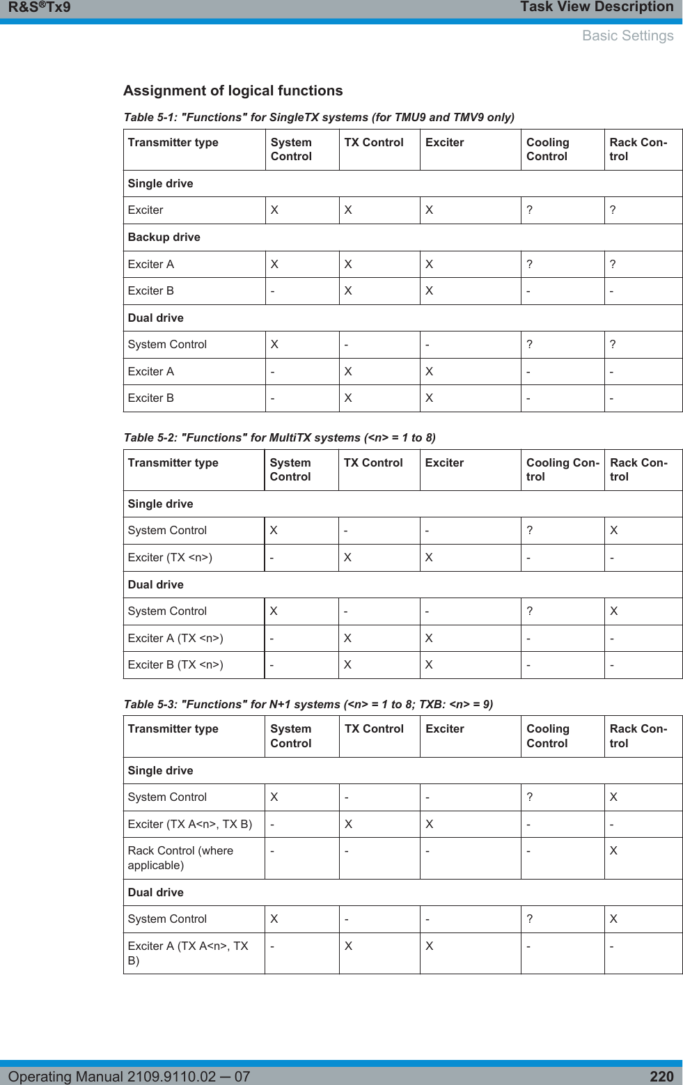
Setup Manual
Navigation menu
Upload a User Manual
Namespaces
Wiki Guide
HTML
PDF
Info
Views
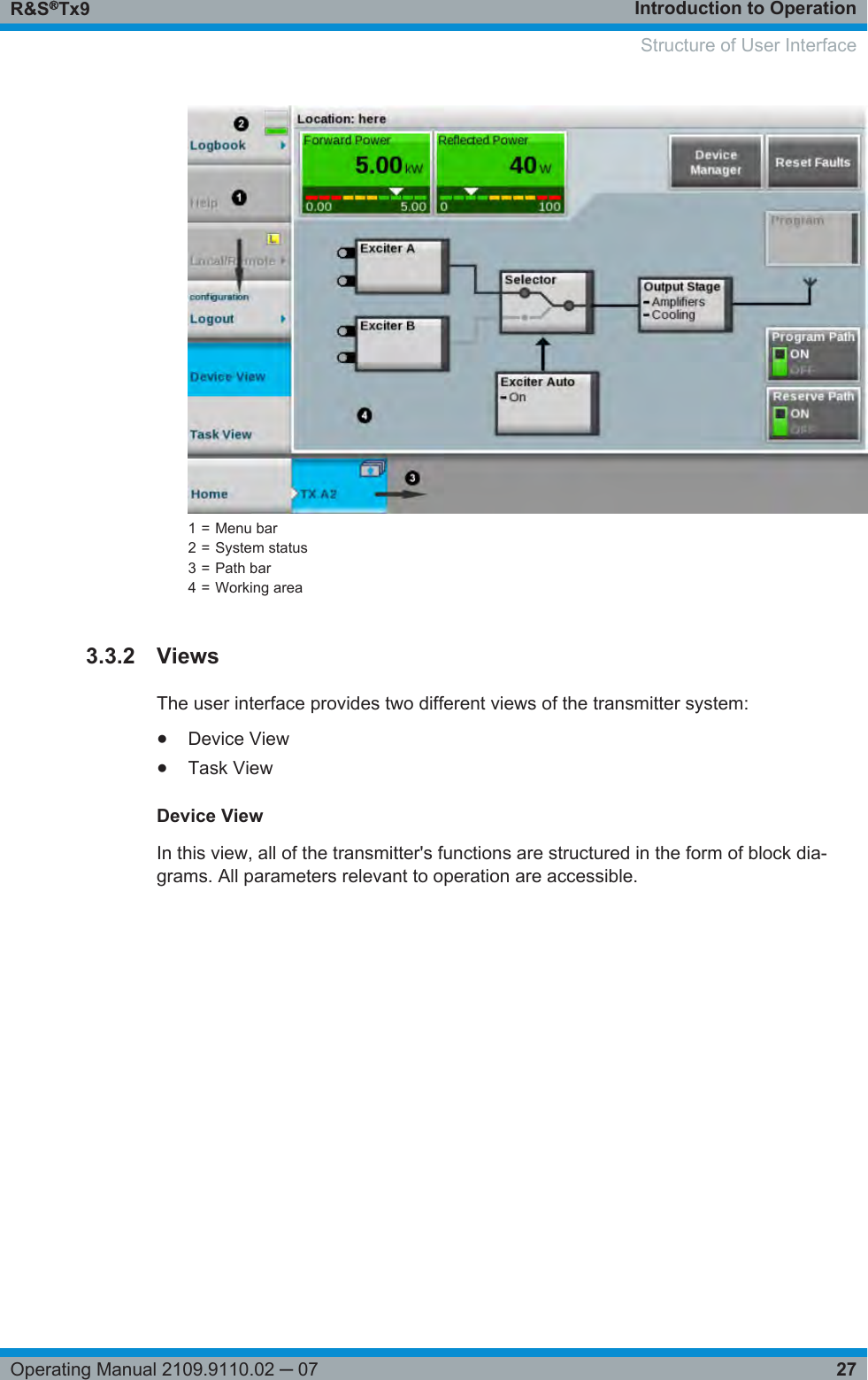
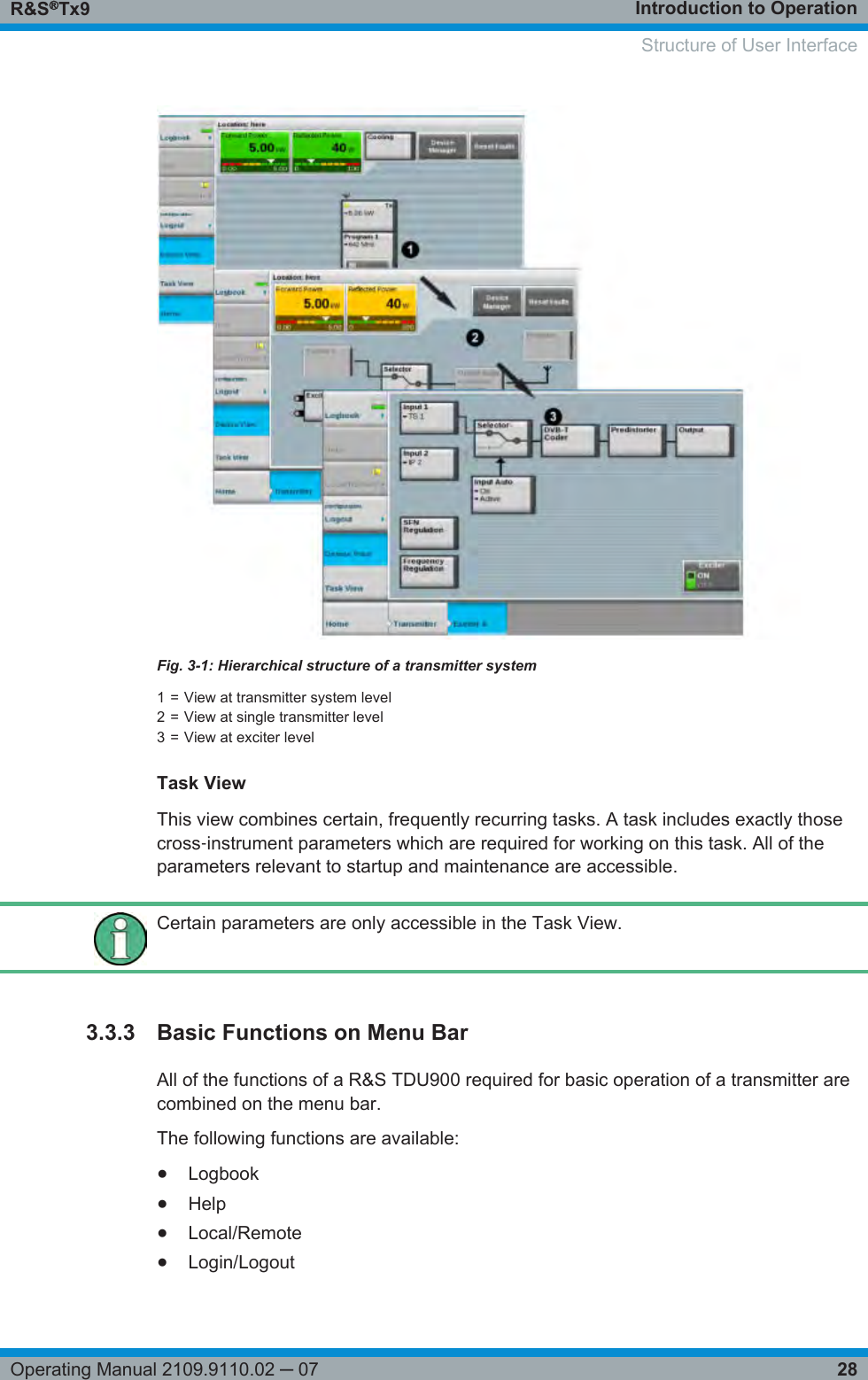
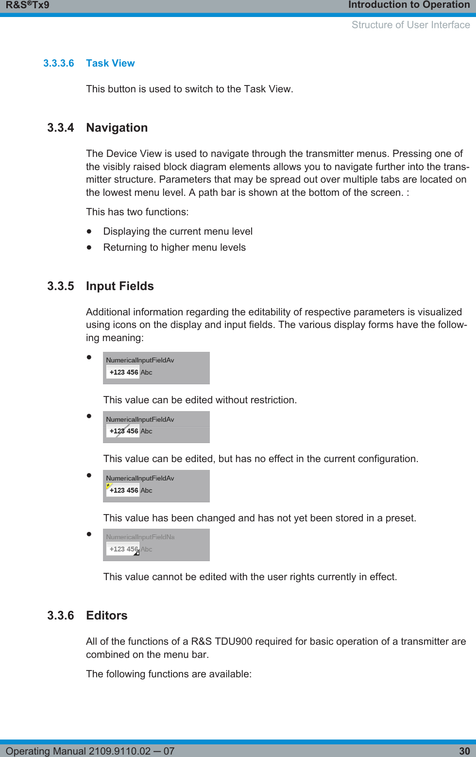
User Manual
Discussion / Help
Navigation