Rohde and Schwarz TMU91 500 Watt UHF ATSC Transmitter User Manual Setup Manual
Rohde & Schwarz Inc 500 Watt UHF ATSC Transmitter Setup Manual
Setup Manual
R&S®Tx9
Transmitter System
Operating Manual
Operating Manual
(E9é:2)
2109.9110.02 ─ 07
Broadcasting
For information only!
This manual, dated April 25, 2014 reflects the
technical status as of that date. There may
have been technical changes since that time.
© 2014 Rohde & Schwarz GmbH & Co. KG
Mühldorfstr. 15, 81671 München, Germany
Phone: +49 89 41 29 - 0
Fax: +49 89 41 29 12 164
E-mail: info@rohde-schwarz.com
Internet: www.rohde-schwarz.com
Subject to change – Data without tolerance limits is not binding.
R&S® is a registered trademark of Rohde & Schwarz GmbH & Co. KG.
Trade names are trademarks of the owners.
The following abbreviations are used throughout this manual: R&S®XYZ1234 is abbreviated as R&S XYZ1234.

Sehr geehrter Kunde,
Sie haben sich für den Kauf
eines Rohde & Schwarz Produk-
tes entschieden. Sie erhalten
damit ein nach modernsten Fer-
tigungsmethoden hergestelltes
Produkt. Es wurde nach den
Regeln unserer Qualitäts- und
Umweltmanagementsysteme
entwickelt, gefertigt und geprüft.
Rohde & Schwarz ist unter ande-
rem nach den Managementsys-
temen ISO 9001 und ISO 14001
zertifiziert.
Der Umwelt verpflichtet
❙Energie-efziente,
RoHS-konforme Produkte
❙Kontinuierliche
Weiterentwicklung nachhaltiger
Umweltkonzepte
❙ISO 14001-zertiziertes
Umweltmanagementsystem
Dear customer,
You have decided to buy a
Rohde & Schwarz product. This
product has been manufactured
using the most advanced meth-
ods. It was developed, manufac-
tured and tested in compliance
with our quality management
and environmental manage-
ment systems. Rohde & Schwarz
has been certified, for exam-
ple, according to the ISO 9001
and ISO 14001 management
systems.
Environmental commitment
❙Energy-efcient products
❙Continuous improvement in
environmental sustainability
❙ISO 14001-certied
environmental management
system
Cher client,
Vous avez choisi d’acheter un
produit Rohde & Schwarz. Vous
disposez donc d’un produit
fabriqué d’après les méthodes
les plus avancées. Le dévelop-
pement, la fabrication et les
tests de ce produit ont été effec-
tués selon nos systèmes de
management de qualité et de
management environnemental.
La société Rohde & Schwarz a
été homologuée, entre autres,
conformément aux systèmes
de management ISO 9001 et
ISO 14001.
Engagement écologique
❙Produits à efcience
énergétique
❙Amélioration continue de la
durabilité environnementale
❙Système de management
environnemental certié selon
ISO 14001
Certied Environmental System
ISO 14001
Certied Quality System
ISO 9001
Quality management
and environmental
management
1171.0200.11 V 05.01
1171020011
ISO-Qualitaets-Zertifikat_1171-0200-11_A4.indd 1 28.09.2012 10:25:08

1171.0200.22-06.00
Customer Support
Technical support – where and when you need it
For quick, expert help with any Rohde & Schwarz equipment, contact one of our Customer Support
Centers. A team of highly qualified engineers provides telephone support and will work with you to find a
solution to your query on any aspect of the operation, programming or applications of Rohde & Schwarz
equipment.
Up-to-date information and upgrades
To keep your instrument up-to-date and to be informed about new application notes related to your
instrument, please send an e-mail to the Customer Support Center stating your instrument and your wish.
We will take care that you will get the right information.
Europe, Africa, Middle East Phone +49 89 4129 12345
customersupport@rohde-schwarz.com
North America Phone 1-888-TEST-RSA (1-888-837-8772)
customer.support@rsa.rohde-schwarz.com
Latin America Phone +1-410-910-7988
customersupport.la@rohde-schwarz.com
Asia/Pacific Phone +65 65 13 04 88
customersupport.asia@rohde-schwarz.com
China Phone +86-800-810-8228 /
+86-400-650-5896
customersupport.china@rohde-schwarz.com

Contents
R&S®Tx9
3Operating Manual 2109.9110.02 ─ 07
Contents
1Information about this Manual..............................................................9
2Safety Instructions...............................................................................11
2.1 Safety Instructions for Transmitter Systems and Equipment................................ 11
2.2 General Safety Instructions....................................................................................... 12
2.2.1 Safety Instructions.........................................................................................................12
2.3 Special Hazard Information........................................................................................19
2.3.1 Hazards from AC Supply Voltage................................................................................. 19
2.3.1.1 AC Power Supply.......................................................................................................... 19
2.3.1.2 Changing Fuses............................................................................................................ 19
2.3.2 Hazards from High‑Energy Electric Circuits..................................................................19
2.3.3 Hazards from RF Radiation...........................................................................................20
2.3.3.1 Obligation to Instruct Personnel.................................................................................... 20
2.3.3.2 RF Shielding..................................................................................................................20
2.3.3.3 Rules When Operating an Amplifier..............................................................................20
2.3.3.4 Rules When Working on an Open Amplifier..................................................................21
2.3.4 Conditions for Assembly Work on Cooling System.......................................................21
2.3.5 Safety Data Sheets for Hazardous Substances............................................................22
3Introduction to Operation....................................................................23
3.1 Operation via R&S TDU900........................................................................................ 23
3.1.1 Opening Display............................................................................................................23
3.1.2 Closing Display............................................................................................................. 23
3.1.3 Using Touchscreen Function........................................................................................ 23
3.2 Operation via Browser................................................................................................24
3.2.1 Connection Setup and Login.........................................................................................26
3.3 Structure of User Interface.........................................................................................26
3.3.1 Elements of User Interface............................................................................................26
3.3.2 Views.............................................................................................................................27
3.3.3 Basic Functions on Menu Bar....................................................................................... 28
3.3.3.1 Logbook........................................................................................................................ 29
3.3.3.2 Help...............................................................................................................................29
3.3.3.3 Local/Remote................................................................................................................ 29

Contents
R&S®Tx9
4Operating Manual 2109.9110.02 ─ 07
3.3.3.4 Login/Logout................................................................................................................. 29
3.3.3.5 Device View.................................................................................................................. 29
3.3.3.6 Task View......................................................................................................................30
3.3.4 Navigation..................................................................................................................... 30
3.3.5 Input Fields....................................................................................................................30
3.3.6 Editors........................................................................................................................... 30
3.3.6.1 Numeric Editor.............................................................................................................. 31
3.3.6.2 Text Editor.....................................................................................................................31
3.3.7 Special Tasks................................................................................................................31
3.3.7.1 Finding an Error............................................................................................................ 31
3.3.7.2 Managing Users............................................................................................................ 32
3.3.8 Logbook........................................................................................................................ 32
3.3.8.1 Intelligent Filtering......................................................................................................... 32
3.3.8.2 Chronological View....................................................................................................... 33
3.3.8.3 Manual Filter (Filter/Options).........................................................................................35
3.3.8.4 Scroll Function.............................................................................................................. 36
4 Device View Description......................................................................39
4.1 System Overview........................................................................................................ 39
4.1.1 Forward Power..............................................................................................................39
4.1.2 Reflected Power............................................................................................................40
4.1.3 Transmitter.................................................................................................................... 40
4.1.4 N+1 Redundancy.......................................................................................................... 41
4.1.4.1 Manual Switchover........................................................................................................41
4.1.4.2 Automatic Switchover....................................................................................................41
4.1.4.3 Configuring N+1 Automatic Function............................................................................ 41
4.2 Transmitter.................................................................................................................. 43
4.2.1 Automatic Switchover....................................................................................................44
4.2.1.1 Automatic Input Signal.................................................................................................. 44
4.2.1.2 Automatic Exciter Switchover........................................................................................47
4.2.2 Transmitter Status.........................................................................................................48
4.2.3 Amplifiers...................................................................................................................... 49
4.2.4 Rack.............................................................................................................................. 64
4.2.5 Output Stage................................................................................................................. 65

Contents
R&S®Tx9
5Operating Manual 2109.9110.02 ─ 07
4.3 Exciter DVB-T2............................................................................................................ 65
4.3.1 Coder for DVB-T2......................................................................................................... 65
4.3.2 Setting Transmit Frequency and Output Power............................................................ 74
4.3.3 Signal Feed................................................................................................................... 75
4.3.3.1 Configuring Physical Inputs...........................................................................................75
4.3.3.2 Input Signal Switchover.................................................................................................80
4.3.4 Controlling Time of Transmission in Single-Frequency Networks (SFN)...................... 82
4.3.4.1 Settings......................................................................................................................... 84
4.3.5 Using Frequency Control.............................................................................................. 86
4.3.6 Precorrection at ATV.....................................................................................................88
4.4 Exciter DVB-T.............................................................................................................. 92
4.4.1 Coder for DVB-T........................................................................................................... 92
4.4.2 Setting Transmit Frequency and Output Power............................................................ 96
4.4.3 Signal Feed................................................................................................................... 96
4.4.3.1 Configuring Physical Inputs...........................................................................................96
4.4.3.2 Input Signal Switchover...............................................................................................101
4.4.4 Controlling Time of Transmission in Single-Frequency Networks (SFN).................... 104
4.4.4.1 Settings....................................................................................................................... 106
4.4.5 Using Frequency Control............................................................................................ 108
4.4.6 Precorrection...............................................................................................................110
4.5 Exciter ISDB-T........................................................................................................... 116
4.5.1 Coder for ISDB-T........................................................................................................ 116
4.5.2 Setting Transmit Frequency and Output Power.......................................................... 121
4.5.3 Signal Feed................................................................................................................. 122
4.5.3.1 Configuring Physical Inputs.........................................................................................122
4.5.3.2 Input Signal Switchover...............................................................................................127
4.5.4 Controlling Time of Transmission in Single-Frequency Networks (SFN).................... 129
4.5.4.1 Settings....................................................................................................................... 132
4.5.5 Using Frequency Control............................................................................................ 134
4.5.6 Precorrection...............................................................................................................136
4.6 Exciter ATSC............................................................................................................. 142
4.6.1 Coder for ATSC...........................................................................................................142
4.6.2 Setting Transmit Frequency and Output Power.......................................................... 144

Contents
R&S®Tx9
6Operating Manual 2109.9110.02 ─ 07
4.6.3 Signal Feed................................................................................................................. 145
4.6.3.1 Configuring Physical Inputs.........................................................................................145
4.6.3.2 Input Signal Switchover...............................................................................................150
4.6.4 Controlling Time of Transmission in Single-Frequency Networks (SFN).................... 152
4.6.4.1 Settings....................................................................................................................... 155
4.6.5 Using Frequency Control............................................................................................ 157
4.6.6 Precorrection...............................................................................................................160
4.7 Exciter DTMB.............................................................................................................165
4.7.1 Coder for DTMB.......................................................................................................... 165
4.8 Exciter ATV................................................................................................................ 169
4.8.1 Coder for ATV............................................................................................................. 169
4.8.2 Setting Transmit Frequency and Output Power.......................................................... 175
4.8.3 Signal Feed................................................................................................................. 176
4.8.4 Using Frequency Control............................................................................................ 179
4.8.5 Precorrection at ATV...................................................................................................181
4.9 Exciter DAB............................................................................................................... 187
4.9.1 Coder for DAB.............................................................................................................187
4.9.2 Using Frequency Control............................................................................................ 189
4.9.3 Precorrection...............................................................................................................191
4.10 Exciter FM.................................................................................................................. 197
4.10.1 Coder for FM............................................................................................................... 197
4.10.2 Setting Transmit Frequency and Output Power for FM...............................................199
4.10.3 Signal Feed................................................................................................................. 200
4.10.3.1 Configuring Physical Inputs.........................................................................................200
4.10.3.2 Input Signal Switchover...............................................................................................203
4.10.4 Using Frequency Control............................................................................................ 204
4.11 Switchless Combiner................................................................................................207
4.11.1 Settings....................................................................................................................... 208
4.12 Cooling System......................................................................................................... 210
4.12.1 Liquid Cooling (High‑Performance).............................................................................210
4.12.1.1 Configuring Switching Thresholds (Pressure) and Flow Volumes.............................. 210
4.12.1.2 Configuring Fans and Pumps......................................................................................213
4.12.1.3 Status of Cooling System............................................................................................214

Contents
R&S®Tx9
7Operating Manual 2109.9110.02 ─ 07
4.12.2 Small Cooling – Simplified Liquid Cooling System (FM Transmitter)..........................214
4.12.2.1 Configuration of Cooling System.................................................................................215
4.12.2.2 Status.......................................................................................................................... 215
4.12.3 Air Cooling (Medium‑Power)....................................................................................... 217
5Task View Description....................................................................... 219
5.1 Basic Settings........................................................................................................... 219
5.2 Parameters: Input Configuration............................................................................. 227
5.3 System Control..........................................................................................................229
5.3.1 Simple Network Management Protocol (SNMP)......................................................... 229
5.3.1.1 General....................................................................................................................... 229
5.3.1.2 Settings on Transmitter End........................................................................................229
5.3.1.3 Settings on Manager End............................................................................................230
5.3.1.4 Which MIBs Must Be Used?....................................................................................... 232
5.3.1.5 Which OIDs from a MIB Must Be Used?.....................................................................233
5.3.1.6 Setting Alarms.............................................................................................................234
5.3.1.7 Testing the SNMP Communications........................................................................... 235
5.3.1.8 Setting Alarms Using SNMP....................................................................................... 236
5.3.1.9 Type plates - the ENTITY MIB.................................................................................... 238
5.4 Maintain Software..................................................................................................... 240
5.4.1 Software Update......................................................................................................... 240
5.4.2 Backup/Restore...........................................................................................................242
5.5 Options.......................................................................................................................244
6Operating the Device Manager......................................................... 247
6.1 Basic Settings........................................................................................................... 247
7User Administration...........................................................................257
7.1 Creating New User Profiles...................................................................................... 257
7.2 Changing User Profiles (Users and Access Rights)..............................................257
7.3 Deleting User Profiles...............................................................................................258
7.4 Closing Active Sessions.......................................................................................... 258

Information about this Manual
R&S®Tx9
9Operating Manual 2109.9110.02 ─ 07
1 Information about this Manual
This manual is part of the documentation for the R&S THU9 transmitter family from
Rohde & Schwarz. The individual manuals for the transmitter family have a modular
structure and complement each other.
Structure
The system manual, which is the central and overarching part of the overall documen-
tation, describes all the steps involved in installing a transmitter.
Operation of the transmitter system after installation and the steps required to put the
system into operation are described in the operating manual.
The service manual describes all maintenance, troubleshooting and service tasks that
customers can carry out themselves. At certain points in the transmitter manual, the
reader is referred to the appropriate operating manual or service manual.
Contents
The manuals for the transmitter family describe all activities required for installation,
startup, operation, maintenance, troubleshooting and servicing of the transmitter and
its component parts. The appendix contains the interface descriptions and the techni-
cal documentation.
Safety
All skilled personnel working with a transmitter or its components have a duty to read
the associated manuals and to follow the safety measures described in the section
"Safety" and given at appropriate points in the manual. It must be ensured that the
transmitter and the individual components of the transmitter are used only for their
intended use. All activities connected with the transmitter or individual transmitter com-
ponents must be carried out by skilled personnel. If activities require additional skills
and qualifications, this is indicated at the appropriate points in the manual.
Symbols and notation
The "warning triangle" symbol refers the reader to potential hazards. The degree of
danger is indicated by different signal words next to the warning symbol.
Instructions are given in numbered steps. All other formatting options are intended to
improve clarity and are self‑explanatory.

Introduction to Operation
R&S®Tx9
23Operating Manual 2109.9110.02 ─ 07
3 Introduction to Operation
The R&S TDU900 is a display unit with a touchscreen function and a graphical user
interface for configuring Tx9 transmitter systems.
3.1 Operation via R&S TDU900
3.1.1 Opening Display
When in the idle state, the display is inside the R&S TDU900 operating unit.
1. Unlock the display by pressing firmly on the trapezoidal area.
2. The display slowly slides forward out of the instrument.
3. Tilt the display until you have reached the most ergonomically comfortable angle
for operation.
3.1.2 Closing Display
1. Tilt the display to a horizontal position until you feel the display engage.
2. Push the display all the way into the R&S TDU900 housing until the display
engages in the transport lock.
3. The display illumination automatically switches off in this state.
Tip: Close the operating unit during long periods of inactivity to prolong the service
life of the backlighting.
3.1.3 Using Touchscreen Function
The display has a touchscreen function for operating all of the transmitter functions.
Using sharp‑edged objects can damage or destroy the surface. Therefore only use
your finger to operate the touchscreen.
1. A light touch on a button is enough to trigger a user action.
2. A button lights up orange for as long as your finger remains there. The action is not
carried out until you remove your finger from the button.
Operation via R&S TDU900

Introduction to Operation
R&S®Tx9
24Operating Manual 2109.9110.02 ─ 07
Tip: To cancel an inadvertently selected action, slide your finger to the side away
from the button highlighted orange and then lift your finger off the touchscreen.
3.2 Operation via Browser
The graphical user interface (GUI) of the Tx9 transmitter series has been implemented
in JAVA to ensure optimum user experience. Java technology provides maximum com-
patibility between different versions of operating systems and browsers.
Supported operating systems
●Windows XP, Windows Vista (32 bit version)
●Windows 7 (32 bit and 64 bit version)
●Windows 8 (32 bit and 64 bit version)
Supported browsers
●Google Chrome
●Mozilla Firefox
●Internet Explorer 7
●Internet Explorer 8
●Internet Explorer 9 (32 bit version)
●Internet Explorer 10 (32 bit and 64 bit desktop version)
Supported JAVA virtual machines
●Oracle (previously: Sun) JRE 7 in 32 bit version
Troubleshooting
You can ensure trouble‑free operation of the GUI in a browser by installing the browser
and the Java VM with their default settings on a computer configured with its factory
settings.
The following solutions are available if the computer settings differ from the standard
installation and there are problems:
●The 64 bit version of Internet Explorer 9 is not supported
–The 32 bit version, which is also installed, must be used
– Use another browser, such as Google Chrome or Mozilla Firefox.
●Internet Explorer 10 is to be used on a 64 bit operating system (Windows 7/8):
"Enhanced Protection Mode" must be disabled in the browser under "Tools >
Options > Advanced" (this is the default setting).
●Windows 8 Modern UI (previously: Metro) does not support Java.
– Start the desktop version of Internet Explorer 10 from the desktop.
– Start Google Chrome or Firefox from a link in Modern UI.
●The error message "Application blocked by security settings" appears on the login
page.
Operation via Browser

Introduction to Operation
R&S®Tx9
25Operating Manual 2109.9110.02 ─ 07
Set the security level to "High" in the Java Control Panel and restart the browser.
●Only a 64 bit Java runtime environment (JRE) is installed.
Remove the 64 bit JRE and install the 32 bit version.
●A 64 bit JRE is installed and required by another application (unlikely)
Install a 32 bit JRE to run in parallel with the 64 bit version.
You can determine the Java version (32 or 64 bit) as follows:
●Open an input prompt window (Start > Run > Open, insert "cmd" and press <OK>)
●Enter: java -d32 -version
●The version number is shown if a 32 bit JRE is installed, otherwise an error mes-
sage appears.
Java security
In order to ensure the optimum protection against malicious software (malware), the
user interface for the Tx9 transmitter series has been implemented in Java. Java tech-
nology eliminates the need to run potentially unsafe ActiveX or Flash plug‑ins in your
browser. Java offers numerous security functions:
●Java security settings
The security level in the Java Control Panel should be set to "High". A correspond-
ing security warning appears then appears when opening a website with Java con-
tents; you have to acknowledge this message. This prevents Java programs from
untrusted websites from being started unintentionally.
●Detecting a secure browser
The Java version installed on the computer should be displayed at the bottom left
corner of the login page only after the security notice for running Java code has
been confirmed. If the Java version is displayed without confirming the security
notice, then you are using an unsecured browser or an outdated version of Java on
your computer.
●Detecting the right web server
The security notice for running the Java code shows the IP address of the transmit-
ter that loaded the Java code to the browser.
Transmitters in the Tx9 series are protected against malware by various security meas-
ures. Nevertheless, it is important to follow this general information on security to pro-
tect other computers in the same network against malware:
●Always keep your browser updated to the latest version!
●Always update your Java runtime environment to the most recent version immedi-
ately after starting your browser.
●Avoid using unsecured browsers, such as MS Internet Explorer 7.
●Always use a firewall to display Internet pages from servers outside your LAN.
●The transmitter should be accessible within its protected intranet at all times. If this
is not technically feasible, take additional measures to secure communications
between the transmitter and browser (e.g. via a VPN).
Operation via Browser

Introduction to Operation
R&S®Tx9
26Operating Manual 2109.9110.02 ─ 07
3.2.1 Connection Setup and Login
1. Create a physical network connection to the transmitter. The following options are
available:
a) Remote access via WAN (Wide Area Network)
b) Local access directly to a transmitter using a LAN cable
2. Start the browser and enter the following information in the address bar:
a) IP address of the transmitter
The website for operating the transmitter is called (login page).
3. Enter your user name and password.
Note: The following login information is preconfigured at the factory
● User name: Query
Password: 1234
● User name: Operation
Password: 1234
● User name: Maintenance
Password: 1234
● User name: Configuration
Password: 1234
Change the user names and passwords after logging in for the first time chap-
ter 3.3.7.2, "Managing Users", on page 32.
After successfully logging in, the actual user interface is displayed.
3.3 Structure of User Interface
3.3.1 Elements of User Interface
The user interface is composed of the following elements:
●Menu bar:
The menu bar provides access to the most important functions.
●System status:
This display provides a constantly visible, general overview of the entire system
status.
●Path bar:
The path bar shows the current position within the menu structure and provides the
ability to quickly return to higher menu levels.
●Working area:
The various tasks and configuration steps are carried out in the working area.
Structure of User Interface
Introduction to Operation
R&S®Tx9
27Operating Manual 2109.9110.02 ─ 07
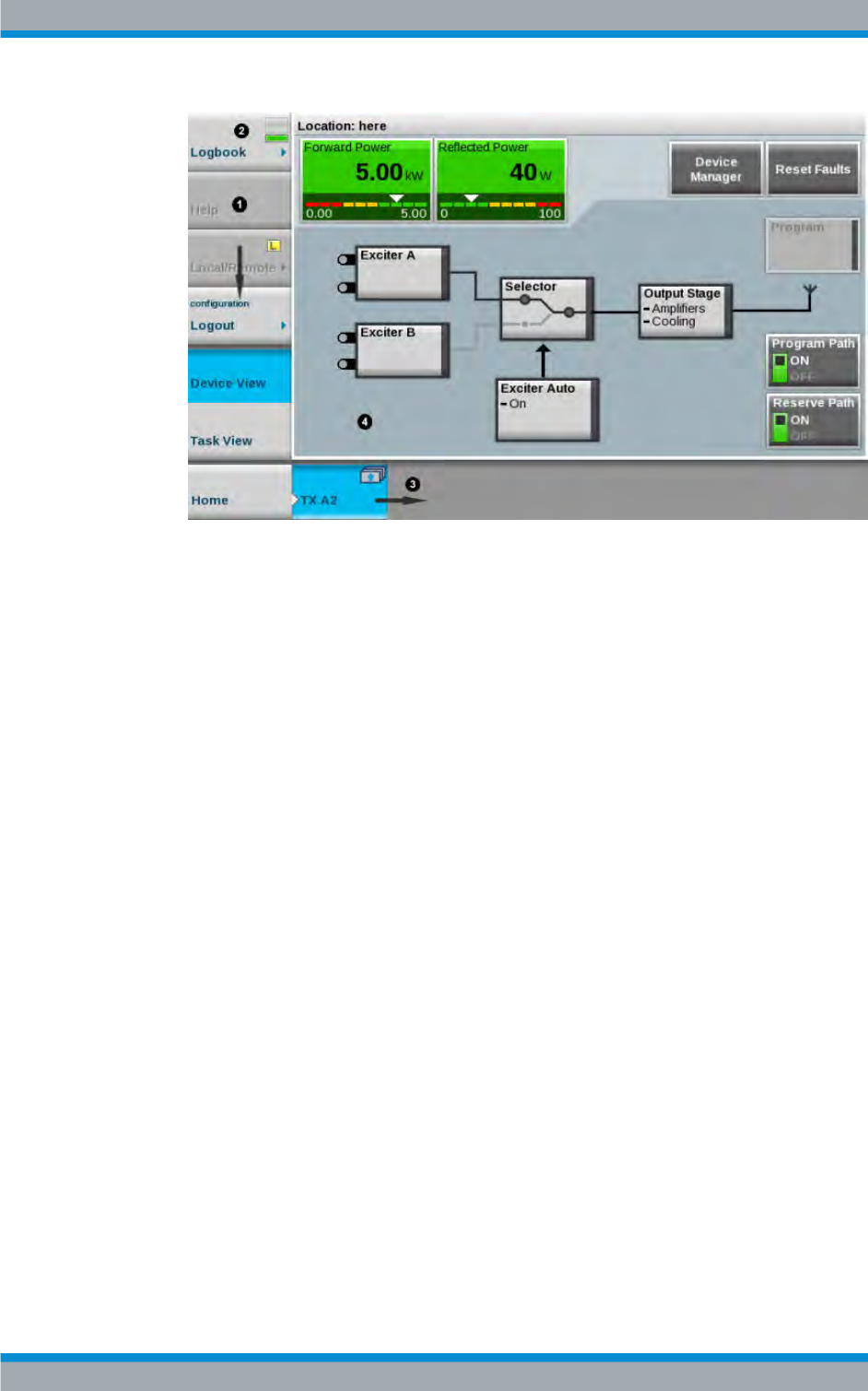
1 = Menu bar
2 = System status
3 = Path bar
4 = Working area
3.3.2 Views
The user interface provides two different views of the transmitter system:
●Device View
●Task View
Device View
In this view, all of the transmitter's functions are structured in the form of block dia-
grams. All parameters relevant to operation are accessible.
Structure of User Interface
Introduction to Operation
R&S®Tx9
28Operating Manual 2109.9110.02 ─ 07
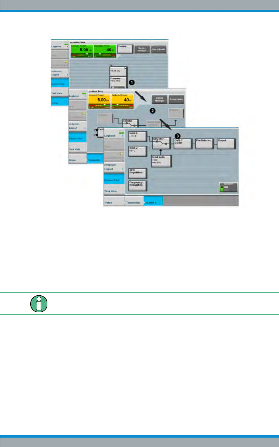
Fig. 3-1: Hierarchical structure of a transmitter system
1 = View at transmitter system level
2 = View at single transmitter level
3 = View at exciter level
Task View
This view combines certain, frequently recurring tasks. A task includes exactly those
cross‑instrument parameters which are required for working on this task. All of the
parameters relevant to startup and maintenance are accessible.
Certain parameters are only accessible in the Task View.
3.3.3 Basic Functions on Menu Bar
All of the functions of a R&S TDU900 required for basic operation of a transmitter are
combined on the menu bar.
The following functions are available:
●Logbook
●Help
●Local/Remote
●Login/Logout
Structure of User Interface
Introduction to Operation
R&S®Tx9
29Operating Manual 2109.9110.02 ─ 07
●Device View
●Task View.
3.3.3.1 Logbook
The logbook is used for logging all system events and for troubleshooting and error
analysis.
3.3.3.2 Help
This button is used to activate the help function. The following steps must be per-
formed:
1. Press the Help button.
All of the elements for which help information is available are identified by a blue
frame.
2. Select the desired element.
The corresponding help information is shown in a separate window.
3.3.3.3 Local/Remote
The transmitter can be operated via both local access and via remote access.
The Local/Remote button allows you to toggle between the two types of access.
The transmitter can be switched from remote operation to local operation from at any
time.
For safety reasons, remote operation is not possible if the system is currently being
operated locally.
The current status (L = Local, R = Remote) is shown directly on the Local/Remote but-
ton. The corresponding status of each transmitter is shown individually for multi‑trans-
mitter systems.
3.3.3.4 Login/Logout
The login dialog allows a user to log in or log out of the system.
3.3.3.5 Device View
This button is used to switch to the Device View.
Structure of User Interface
Introduction to Operation
R&S®Tx9
30Operating Manual 2109.9110.02 ─ 07
3.3.3.6 Task View
This button is used to switch to the Task View.
3.3.4 Navigation
The Device View is used to navigate through the transmitter menus. Pressing one of
the visibly raised block diagram elements allows you to navigate further into the trans-
mitter structure. Parameters that may be spread out over multiple tabs are located on
the lowest menu level. A path bar is shown at the bottom of the screen. :
This has two functions:
●Displaying the current menu level
●Returning to higher menu levels
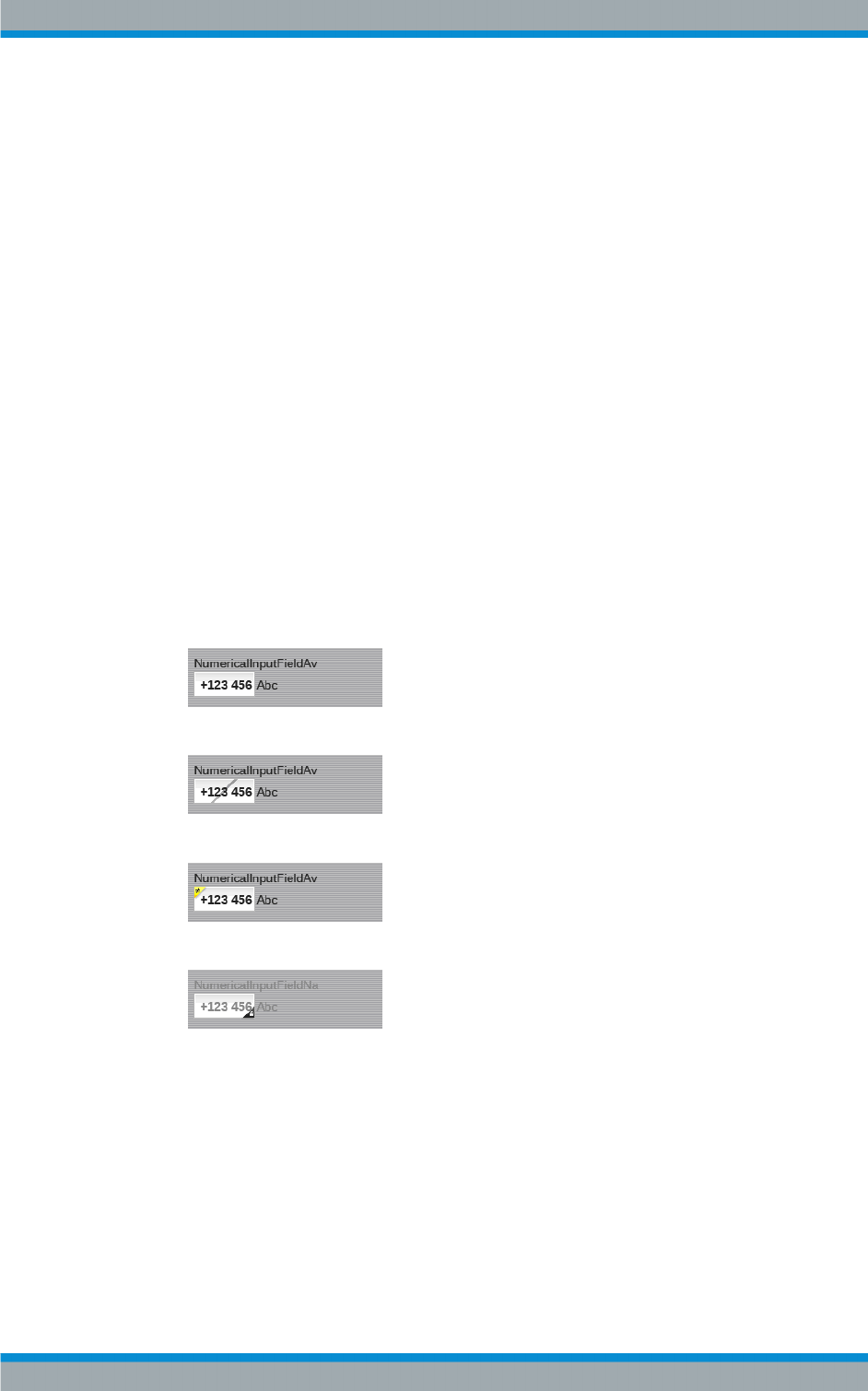
3.3.5 Input Fields
Additional information regarding the editability of respective parameters is visualized
using icons on the display and input fields. The various display forms have the follow-
ing meaning:
●
This value can be edited without restriction.
●
This value can be edited, but has no effect in the current configuration.
●
This value has been changed and has not yet been stored in a preset.
●
This value cannot be edited with the user rights currently in effect.
3.3.6 Editors
All of the functions of a R&S TDU900 required for basic operation of a transmitter are
combined on the menu bar.
The following functions are available:
Structure of User Interface
Introduction to Operation
R&S®Tx9
31Operating Manual 2109.9110.02 ─ 07
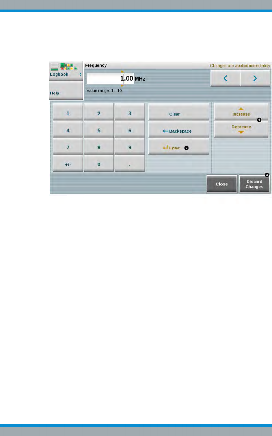
3.3.6.1 Numeric Editor
The numeric editor features the following functions.
1 = By pressing one of these buttons, the value is changed directly in the display without the use of the enter
button.
2 = The value entered using the numeric keypad is accepted by the system by pressing this button.
3 = Pressing this button discards all of the changes made in this window and restores the original value.
Violating the allowed value ranges causes an error message to appear and disables
the input elements (Increase/Decrease/Enter).
3.3.6.2 Text Editor
The text editor allows letters, digits and special characters to be entered.
3.3.7 Special Tasks
3.3.7.1 Finding an Error
There are two ways of locating an error:
●Block diagrams
You can use the traffic light signaling of the elements in the block diagrams to find
the cause of an error in just a few steps, as long as the error is currently active.
Structure of User Interface

Introduction to Operation
R&S®Tx9
32Operating Manual 2109.9110.02 ─ 07
Valuable information about an error's cause and tips for correcting the error can be
retrieved using the help function of the respective error message.
●Logbook
Complex error situations including behavior over time can be analyzed using the
logbook. The help function again provides a multitude of valuable information.
3.3.7.2 Managing Users
User management is only available if the R&S TDU900 is operated using a browser.
The following login must be selected for this purpose:
User name: Superuser
Password: 1234
For more details, see chapter 7, "User Administration", on page 257.
3.3.8 Logbook
All system events are recorded in the logbook. The following functions are available for
simplifying troubleshooting and error analysis:
●Intelligent filtering
Events are intelligently prefiltered based on the context of the menu currently open.
●Chronological view
Events are shown in their chronological order. Associated events are marked
accordingly.
●Manual filter (Filter and Options)
Events or event groups can be chosen selectively with the help of specific criteria.
●Scroll function
Enables fast navigation in long event lists
3.3.8.1 Intelligent Filtering
Depending on which menu is used to open the logbook, only events relevant in the
context of the respective menu are displayed. These filters significantly increase clarity
in the logbook.
●System overview
Opening in the system overview: With MultiTX and N+1 systems, shows all of the
events affecting the core components (e.g. cooling, N+1 automatic switchover) as
well as the most important messages from individual transmitters within the sys-
tem. With SingleTX systems, all of the detailed messages from the transmitter are
also shown.
●Transmitter level:
Opening in a transmitter-specific menu: Shows in detail all of the events that affect
the respective transmitter (incl. exciters).
Structure of User Interface
Introduction to Operation
R&S®Tx9
33Operating Manual 2109.9110.02 ─ 07
Depending on which menu is used to open the logbook, only events relevant in the
context of the respective menu are displayed. These filters significantly increase
clarity in the logbook.
●Exciter level
Shows in detail all of the events that affect the respective exciter.
A total of up to 500 events is logged in the logbook.
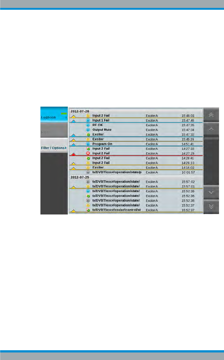
3.3.8.2 Chronological View
All of the event messages are listed here in strictly chronological order. The most
recent messages are always shown at the top of the list.
Fig. 3-2: Logbook – chronological view
A thread consists of a group of messages that refer to the same event. The color of the
thread is determined by the most critical message within the thread. Clicking a thread
marker opens a window containing the associated messages.
Structure of User Interface
Introduction to Operation
R&S®Tx9
34Operating Manual 2109.9110.02 ─ 07
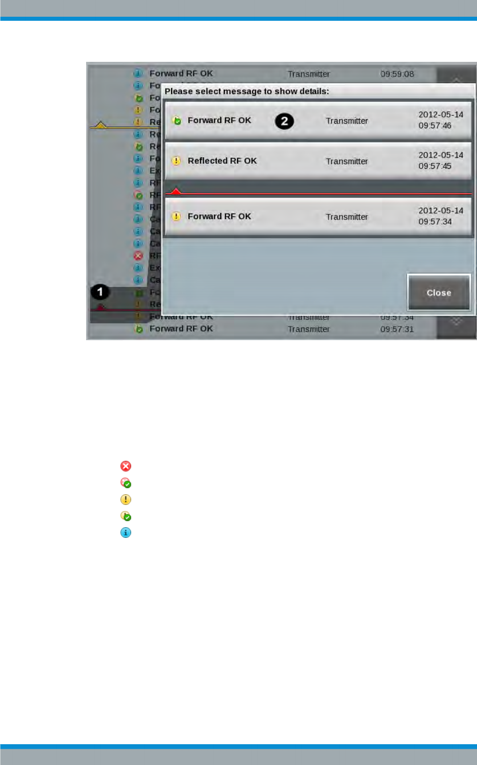
Fig. 3-3: Logbook – thread
1 = Thread marker
2 = Click to open detail view
For most messages there is an entry indicating when the message occurred and when
it disappeared.
Each entry consists of the following information:
●Alarm level
– Error
– Error no longer present/remedied
–Warning
– Warning no longer present
– Info
●Error message text
●System component (control, amplifier, exciter, etc.)
●Time
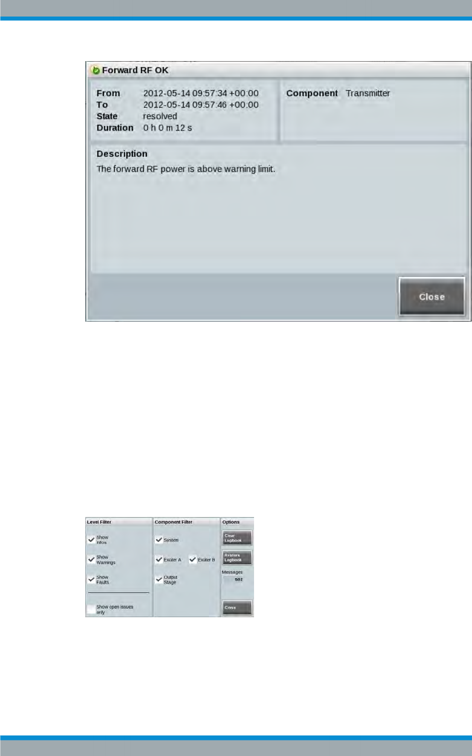
Clicking an entry within the thread view displays a detailed description with the follow-
ing contents.
Structure of User Interface
Introduction to Operation
R&S®Tx9
35Operating Manual 2109.9110.02 ─ 07
●From: / To:
Displays the time when an event starts or ends.
●State:
Indicates whether an event is still active or already remedied.
●Duration:
Indicates how long an event was active.
●Component:
Indicates the system components affected by an event.
●Description:
Displays a detailed description of an event.
3.3.8.3 Manual Filter (Filter/Options)
Fig. 3-4: Logbook – filter/options
The filter function allows filtering of the messages according to the following criteria:
●Level filter:
Structure of User Interface

Introduction to Operation
R&S®Tx9
36Operating Manual 2109.9110.02 ─ 07
The messages can be filtered selectively according to individual or multiple levels
(Info | Warning | Fault) at the same time by selecting/deselecting the checkboxes
"Show Infos", "Show Warnings" and "Show Faults".
Selecting the "Show open issues only" checkbox will cause only messages that are
still active to be displayed, in other words, messages that still have not been rem-
edied,
●Component filter:
The messages can be filtered selectively according to individual or multiple system
components (System | Exciter A/B | Output Stage) at the same time by selecting/
deselecting the checkboxes.
●Options:
The following options are available:
– Clear logbook
"Clear Logbook" is used to completely delete the contents of the logbook.
– Restore logbook
"Restore Logbook" is used to restore the logbook after it has been inadvertently
deleted.
– Messages
The "Messages" display shows the number of entries in the logbook.
– Close
"Close" is used to close the entire filter function.
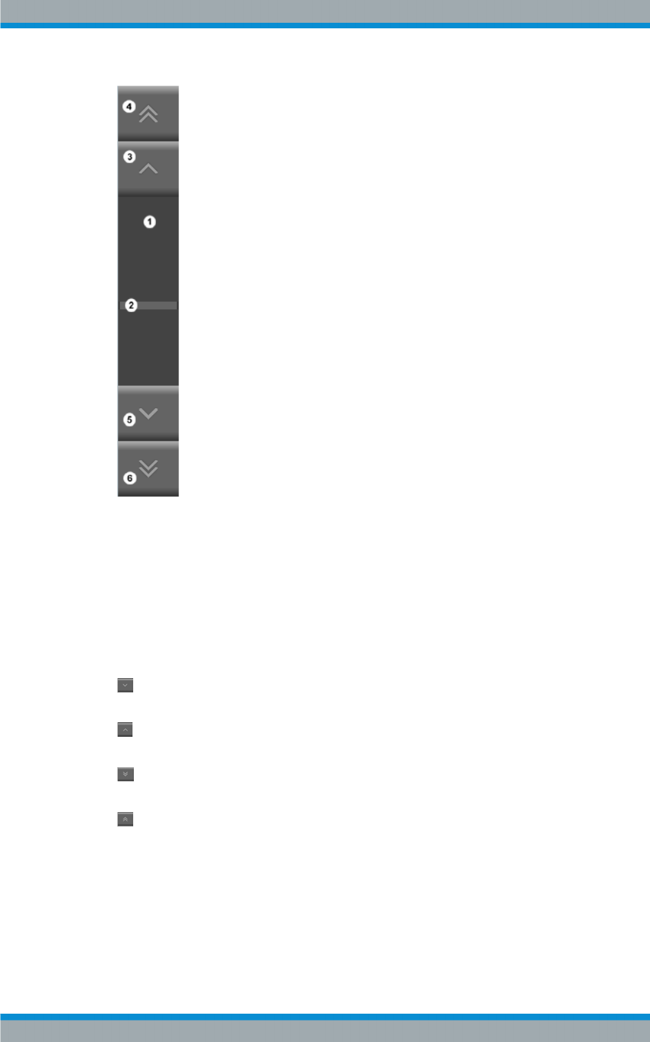
3.3.8.4 Scroll Function
The scroll function enables navigation within a long event list and the selection and
detailed view of specific events.
Structure of User Interface
Introduction to Operation
R&S®Tx9
37Operating Manual 2109.9110.02 ─ 07
Fig. 3-5: Scroll functions
1 = Scroll box
2 = Scroll thumb
3 = Entry up
4 = Page up
5 = Entry down
6 = Page down
Clicking inside the scroll box moves the "scroll thumb" directly to the corresponding
position.
Entry down: This button is used to scroll down by one entry in the direction of the
oldest date.
Entry up: This button is used to scroll up by one entry in the direction of the most
recent date.
Page down: This button is used to scroll by one page at a time in the direction of the
oldest date.
Page up: This button is used to scroll by one page at a time in the direction of the
most recent date.
Structure of User Interface
Device View Description
R&S®Tx9
39Operating Manual 2109.9110.02 ─ 07
4 Device View Description
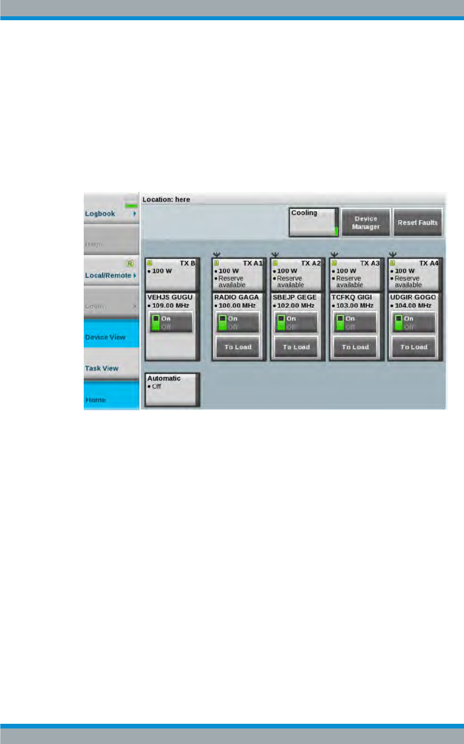
4.1 System Overview
The screenshot below shows the Device View Home menu view. It represents the
transmitter system level. The function of the individual buttons and the meaning of spe-
cific parameters are explained in the following chapters.
Fig. 4-1: Device View Home menu view
4.1.1 Forward Power
●Path:Device View Home > TX An
The "Forward Power" field shows the forward power of the transmitter system in kW.
This field lights up green provided that the forward power is above the user‑selectable
warning threshold. If the forward power drops to the warning level, the field lights up
yellow. If the forward power drops below the user‑selectable fault threshold, the field
lights up red.
Pressing the green area opens the "Power and Limits" view. The following user‑select-
able values are displayed in the Forward Power field:
●Power (in percent)
Forward power: can be set between 0 % and 130 %. The nominal transmitter
power corresponds to 100 %.
●Warning Limit (in dB)
Warning threshold: can be set between 0 dB and ‒20 dB.
System Overview

Device View Description
R&S®Tx9
40Operating Manual 2109.9110.02 ─ 07
●Fault Limit (in dB)
Fault threshold: can be set between 0 dB and ‒20 dB.
●RF Fail Timeout (in s).
Delay time: can be set between 0 s and 10 s. This is the time between undershoot-
ing of the "Fail Limit" fault threshold and indication of the fault in the transmitter sta-
tus display.
4.1.2 Reflected Power
●Path:Device View Home > TX An
The "Reflected Power" field indicates the reflected power of the transmitter system in
W. This field lights up green provided that the reflected power is below the user‑select-
able warning threshold. If the reflected power exceeds this threshold, the field lights up
yellow. If the reflected power exceeds the user‑selectable fault threshold, the field
lights up red.
Pressing the green area opens the "Power and Limits" view. The following user‑select-
able values are displayed in the Forward Power field:
●Warning Limit (in dB)
Warning threshold: can be set between ‒28 dB and ‒17 dB.
●Fault Limit (in dB)
Fault threshold: can be set between ‒17 dB and ‒14 dB.
4.1.3 Transmitter
The icons and buttons for the TX A1 to TX An and TX B transmitters (depending on the
system configuration) are shown in the "Device View Home" menu overview.
The function of the buttons is explained in the next chapter, see chapter 4.2, "Transmit-
ter", on page 43.
Name Description Value range Access right
Program On Switch used to switch the components in the program path
of the transmitter on and off.
Off; On Operation
Reserve On Switch used to switch all components in the standby path of
the transmitter on and off (standby exciter with "dual drive"
redundancy concept and standby output stage with "active
PA Reserve" redundancy concept).
Off; On Operation
Reset Faults Switch used to reset all faults stored in the transmitter.
Stored faults are: Reflection Fail.
Resetting stored faults can cause automatic redundancy
functions, which are currently in the switched-over state, to
switch back to their original preselected state.
Operation
System Overview

Device View Description
R&S®Tx9
41Operating Manual 2109.9110.02 ─ 07
Program
The currently active program 1 can be switched off using the "Program 1 – ON/OFF"
button.
4.1.4 N+1 Redundancy
The task of the N+1 automatic function is to provide a B standby transmitter for up to
eight A transmitters. This B transmitter takes over the program of an A transmitter if an
A transmitter signals a fault. The output of the B transmitter is normally connected to a
dummy antenna. The B transmitter is connected to an antenna by the N+1 automatic
function as soon as the B transmitter takes over the program of the A transmitter.
4.1.4.1 Manual Switchover
Manual switchover of a program from an A transmitter to the B transmitter is performed
by connecting the A transmitter concerned to the dummy antenna (button: To Load on
the corresponding A transmitter). As a result of this switchover, a) the A transmitter
becomes the standby transmitter for the B transmitter and b) the B transmitter is now
no longer available as the standby transmitter for other A transmitters (exception: prior-
ity control).
4.1.4.2 Automatic Switchover
If the N+1 automatic function is active and ready for operation and the A transmitter is
available for the N+1 automatic function, a fault in the A transmitter causes the pro-
gram to switch over to the B transmitter. The N+1 automatic function signals the
switchover by changing its status to "changed". The user can now either acknowledge
the switchover by pressing the "Accept changeover" key and adopt it as the new oper-
ating state, or attempt by pressing the "Reset Faults" key to reset the N+1 automatic
function to the original state and to delete the fault which caused the switchover.
4.1.4.3 Configuring N+1 Automatic Function
The switching behavior of the N+1 automatic function with regard to checkout times
and automatic switchback can be configured according to individual requirements. Fur-
thermore, for the B transmitter it is possible to define the A transmitter from which the
program settings are to be adopted when the B transmitter operates as a standby
transmitter.
Configuring Program‑Specific Settings
The B transmitter must store all program‑specific settings of all A transmitters internally
so that they can be activated immediately in the event of a fault. Program‑specific set-
tings are all settings which directly affect the signal path through the transmitter, i.e.
settings for the coder, the exciter inputs and outputs, the transmit frequency and the
output power. The program‑specific settings are made at the A transmitters and stored
using the menu item "Save Preset" in the Task View of the A transmitter. The settings
System Overview

Device View Description
R&S®Tx9
42Operating Manual 2109.9110.02 ─ 07
stored for the A transmitters are synchronized with the B transmitter automatically even
if the B transmitter was switched off when the settings were stored. If the program‑spe-
cific settings are changed at A transmitters without these settings being stored as pre-
sets, the changes will not be available on the B transmitter in the event of a switchover.
Presets can only be stored on the A transmitters.
Configuring Power‑Specific Settings
All settings which have been stored on an A transmitter as presets and synchronized
with the B transmitter can be overwritten individually in the B transmitter. This can be
used to calibrate the power test points of the B transmitter to the frequency and output
power of the respective A transmitter. To do so, the "Program Settings" of the A trans-
mitter concerned must be activated in the B transmitter ("Load Program Settings") and
then the corresponding settings must be made in the menus of the B transmitter.
Finally, the changed settings must be stored in the B transmitter ("Save Tx B Set-
tings"). This must be repeated for all programs that the B transmitter can take over.
Settings that have been changed directly at the B transmitter are no longer synchron-
ized with the B transmitter using the "Save Preset" function on the A transmitters. It is
therefore recommended to overwrite the preset settings of the A transmitters at the
B transmitter only for purposes of calibrating the power test points, and never to make
program‑specific settings directly at the B transmitter.
If a setting has been inadvertently changed on the B transmitter and stored for an
A transmitter, automatic synchronization can be reactivated for this setting value in the
following way:
●On the B transmitter, set the setting value to the same value as on the A transmit-
ter.
●Press "Save Tx B Settings" in the menu of the N+1 automatic function
This setting value is now synchronized again together with all program‑specific setting
values of the A transmitter.
"N+1 Automatic" parameters
●Path: "Device View (Home)" > "Automatic" > "n+1 Automatic"
Name Description Value range Access right
Automatic (Auto
Switch)
Used to activate the n+1 automatic function. If the n+1 automatic func-
tion is active, a fault within an A transmitter causes a switchover and
the program of the A transmitter is taken over by the standby B trans-
mitter.
On, Off Read / Write
(Operation)
Guard Time (Auto
Switch)
Checkout time which must pass before an A transmitter is replaced by
the standby B transmitter. A long Guard Time suppresses switchover
operations caused by brief faults, but also reduces the availability of
the program.
0 s to 60 s Read / Write
(Maintenance)
System Overview

Device View Description
R&S®Tx9
43Operating Manual 2109.9110.02 ─ 07
Name Description Value range Access right
Switch Mode
(Auto Switch)
Used to define the switching behavior of the N+1 automatic function.
Single switch: Switchover of an A transmitter to the B transmitter can
occur once only. Multiple switch: Following a switchover operation, the
system can switch back to the A transmitter automatically when the
A transmitter no longer signals a fault but the B transmitter indicates a
fault. If priority control is active, this switch should be set to Multiple
Switch.
Single, Multiple Read / Write
(Maintenance)
Load Program
Settings (Auto
Switch)
Used to load the program‑specific settings of an A transmitter to the
B transmitter.
Tx A1, Tx A2, Tx
A3, Tx A4, Tx A5,
Tx A6, Tx A7, Tx
A8
Read / Write
Save Tx B Set-
tings (Auto
Switch)
Used to save settings, which have been changed relative to the loaded
A transmitter, in the B transmitter.
Automatic (Sta-
tus)
Indicates the status of the N+1 automatic function by means of three
elements. If the N+1 automatic function is on, it can be "ready"/"not
ready" and at the same time "changed"/"not changed".
On, Off, Ready,
Not Ready,
Changed
Read Only
Tx B is Reserve
for (Status)
If a switchover operation has taken place, this indicates which program
of an A transmitter the B transmitter has taken over.
Tx A1, Tx A2, Tx
A3, Tx A4, Tx A5,
Tx A6, Tx A7, Tx
A8
Read Only
RF Switch (Sta-
tus)
Indicates a fault if in the event of a switchover one of the RF switches
could not be turned correctly or if one of the jumpers has not been
positioned correctly on the patch panel (if used).
Ready / Not
Ready
Read Only
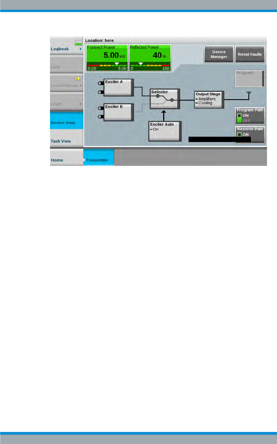
4.2 Transmitter
The screenshot below shows the Transmitter menu view. It represents the single trans-
mitter level. The function of the individual buttons and the meaning of specific parame-
ters are explained in the following chapters.
Transmitter
Device View Description
R&S®Tx9
44Operating Manual 2109.9110.02 ─ 07
4.2.1 Automatic Switchover
4.2.1.1 Automatic Input Signal
The R&S®TCE900 in the R&S®TCE900 exciter configuration has an automatic switch-
over function which, in the event of a signal failure at one logical input, switches over to
the other logical input (provided that a valid input signal is available at the other logical
input). Before a failure occurs, the preselected input is active. The way in which this
automatic switchover function operates is determined by the following factors:
Automatic input switchover ON/OFF
If automatic switchover is OFF, the preselected input remains active even if the input
signal fails. If automatic switchover is ON and there is a failure at the (preselected)
input, switchover to the standby input takes place.
Input priority (Preferred Input = Logical Input 1/2)
Following switchover of the priority logical input to the standby input, the automatic sys-
tem switches back to this priority input as soon as a signal returns. All switchover oper-
ations are delayed for the set delay times. If the signal fails at both the operating input
and the standby input, the priority input always remains active.
Inputs with equal priority (Preferred Input = none)
Following switchover of the active logical input, the second input with the same priority
remains active until the input signal fails on this input also. The automatic system
switches back to the preselected input, but only if a signal is present on it once again
(and if "Switch to" is set to "reserve & back"). All switchover operations are delayed for
the set delay times.
Transmitter

Device View Description
R&S®Tx9
45Operating Manual 2109.9110.02 ─ 07
Selecting this operating mode minimizes the number of switchover operations and, in
certain cases, the number of breaks in transmission.
Direction of switchover (Switch to)
The "to reserve and back" switch position enables switchover in both directions, i.e. to
and from the standby input, depending on which of the two logical inputs is currently
faulty.
The "reserve" switch position ensures that switchover takes place once only. Following
switchover, the automatic system switches to "switched" and the "Active" indicator dis-
appears.
Switchback to the preselected input takes place when the active input is switched over
by pressing the input selector switch (Selector) and then selecting the preselected
input.
If the switch is set to "reserve", the switchback to the preselected input is suppressed.
Manual switchover between inputs
The input can be switched over in the "Home" > "Transmitter" > "Exciter" menu by
pressing the input selector switch ("Selector") and then selecting the desired input.
Depending on the configuration and switching state (ON/OFF) of the automatic input
signal switchover function, this menu contains either the switch used to change the
preferred input or the switch used to switch over the active input.
The automatic input signal switchover function is configured in the following way:
1. Navigate to the following destination using the menu bar:
"Devices" > "Tx<n>" > "Exciter A|B" > "Input Auto"
2. The following parameters must be defined on the Automatic tab:
a) for Configuration:
●Automatic:
●Preferred Input:
●Guard Time to Reserve:
●Guard Time Back:
●Switch to:
b) for Reserve Control:
●If Reserve Input Fails.
c) for Seamless Switching:
●Seamless Switching:
●Delay between Inputs
●Pre-Delay:
Transmitter

Device View Description
R&S®Tx9
46Operating Manual 2109.9110.02 ─ 07
d) for Input Control:
●Force Exciter Changeover:
●Mute on Input Fail
●If Reserve Input fails
"Automatic input signal switchover" parameters
Name Description Value range Access right
Automatic (State) Indicates the state of the automatic input signal switchover function.
●Not Ready:
The automatic switchover function is not ready. An input signal is
not present at the standby input or a switchover has already taken
place and the automatic switchover function is configured such
that automatic switchback is not permitted.
●Ready:
The automatic switchover function is ready to switch the currently
active input over to the input currently not in use as soon as the
input signal of the currently active input fails.
●Changed:
The automatic switchover function has switched over from the
preferred input to the standby input.
undefined, Not
Ready, Ready,
Changed+Ready,
Changed+Not
Ready
Read only
Seamless Switch-
ing
Indicates whether seamless switching of the input signal is possible.
"Not Possible" always appears if only one input signal is supplied or in
cases where two different data streams are present at the two inputs. If
seamless switching is possible, it always takes place immediately
when required, regardless of whether a "Guard Time to Reserve" or
"Guard Time Back" has been set.
undefined, not
Possible, Possi-
ble
Read only
Automatic Activates automatic switchover of the input signal to the standby input
if the preferred input fails.
Off, On Operation
Preferred Input Used to select the preferred input which the automatic input signal
switchover function should use whenever possible.
Input 1, Input 2,
No Preference
Operation
Active Input Used to select the active input to be used when the automatic input
signal switchover function is off. If the automatic switchover function is
on, the input can only be switched over using this switch if Preferred
Input is set to "No Preference" or a switchover to the standby input has
taken place.
Input 1, Input 2 Operation
Switch to Used to set the operational response of the automatic switchover func-
tion.
●"To Reserve Only":
The automatic switchover function switches over once from the
preferred input to the standby input and then assumes the "not
ready" state". Switching the active input over manually to the pre-
ferred input reactivates the automatic switchover function.
●"To Reserve and Back":
Following successful switchover to the standby input, the auto-
matic switchover function can also switch back automatically if the
signal at the standby input fails.
Reserve Only,
Reserve & Back
Maintenance
Guard Time to
Reserve
Used to set a guard time which must elapse before the automatic
switchover function switches over to the standby input if the input sig-
nal at the preferred input fails. The set guard time has no effect if
seamless switching is possible. In this case, the switchover always
takes place immediately without interruption (i.e. seamlessly).
Maintenance
Transmitter

Device View Description
R&S®Tx9
47Operating Manual 2109.9110.02 ─ 07
Name Description Value range Access right
Guard Time Back Used to set a guard time which must elapse before the automatic
switchover function switches back to the preferred input if the input sig-
nal at the standby input fails. If seamless switching is possible, switch-
over always takes place immediately without interruption regardless of
the set guard time. If "to Reserve Only" was selected as the "Direc-
tion", the set guard time has no effect.
Maintenance
If Reserve Fails Used to determine whether the signal at the standby input is to be
monitored.
●If the transmitter is operated with only one input signal or the
standby input is connected only temporarily, "Do Not Show Warn-
ing" must be selected.
●If two redundant input signals are normally supplied to the trans-
mitter, "Show Warning" must be selected.
Do Not Show
Warning, Show
Warning
Maintenance
4.2.1.2 Automatic Exciter Switchover
The automatic exciter switchover function enables a faulty exciter to be automatically
switched over to a functional standby exciter.
In the "Exciter Automatic" menu it is possible to switch automatic switchover between
two exciters on and off and to select the basic operating behavior of the function. The
"Switch Mode" switch is used to select whether automatic switchover to a standby
exciter is to take place once only (Single Switch) or whether a switchback is also to be
performed if the standby exciter signals a fault, but the preselected exciter is no longer
faulty (Multiple Switch).
It is also possible to set a guard time which must always expire before a switchover
can take place. This prevents unwanted switchover operations resulting from brief fault
events.
Operation
One of the two exciters can be preselected for operation by pressing the exciter selec-
tor switch (or via the ExciterAuto -> Exciter Switch tab). This exciter is switched on
together with the output stage by pressing the "Program Path On" switch (in the
"Transmitter" menu). If necessary, the RF of the standby exciter can be switched on for
measuring and monitoring purposes by pressing the "Reserve Path (on)" switch (in the
"Transmitter" menu). A switchover operation causes the standby exciter to become the
main exciter and vice versa. The ON/OFF switches then act on the other exciter in
each case.
"Single Switch" Mode
If a fault occurs in the preselected exciter, the automatic switchover function will swap
the main and standby exciter and display an "Automatic changed" message.
Either the new state can now be accepted by changing the "preselected exciter"
("Automatic changed" disappears) or the automatic switchover function can be reset to
its original state by pressing "Reset Faults" (in the "Transmitter" menu).
Transmitter

Device View Description
R&S®Tx9
48Operating Manual 2109.9110.02 ─ 07
"Multiple Switch" Mode
This mode is identical to "Single Switch", except that following a double switchover
operation the "preselected" exciter becomes the active exciter again. The "Automatic
Changed" message is still displayed in this case. To delete this message, either the
new state of the automatic switchover can be adopted by pressing the "Recommand
Selection" button (in the "Transmitter" > "Exciter Auto" menu, "Exciter Switch" tab) or
the original state can be assumed again by pressing "Reset Faults" (in the Transmitter
menu).
4.2.2 Transmitter Status
Name Description Value range Access right
Program On Indicates whether all components in the program path of the
transmitter have been switched on or off (reserve exciter
with "Dual Drive" redundancy concept and reserve output
stage with "active PA reserve" redundancy concept).
Off; On Read Only
Reserve On Indicates whether all components in the reserve path of the
transmitter have been switched on or off (reserve exciter
with "Dual Drive" redundancy concept and reserve output
stage with "active PA reserve" redundancy concept).
Off; On Read Only
Overall LED Gray: Off
Green: OK
Yellow: Warning
Red: Fault
Read Only
RF LED Gray: Off
Green: OK
Yellow: Warning
Red: Fault
Read Only
Reflection LED Gray: Off
Yellow: Warning
Red: Fault
Read Only
Automatic (Backup Drive /
Dual Drive)
Indicates whether the automatic exciter switchover function
has been activated. If the automatic switchover function is
active, the system will switch over to the standby exciter if
the active exciter fails.
Off; On Read Only
Ready (Backup Drive / Dual
Drive)
Indicates whether the automatic exciter switchover function
is ready. If "not ready" is indicated, either the automatic
exciter switchover function has already switched over to the
standby exciter or a fault has occurred in the exciter switch.
Yes; No Read Only
changed Over (Backup
Drive / Dual Drive)
Indicates whether the automatic exciter switchover function
has switched over to a reserve exciter.
Read Only
switch Failed (Backup
Drive / Dual Drive)
Indicates that switchover to the reserve exciter has failed. Read Only
Transmitter
Device View Description
R&S®Tx9
49Operating Manual 2109.9110.02 ─ 07
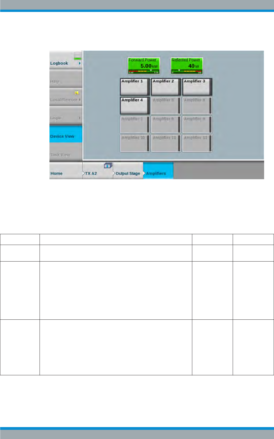
4.2.3 Amplifiers
Fig. 4-2: "Amplifiers" menu view (Multi
‑
Tx)
R&S PHU901/R&S PHU902/R&S PHV902: "Status" parameters
●Path: "Device View (Home)" > "Tx <n>" > "Output Stage" > "Amplifiers" > "Ampli-
fier <n>" > Tab "Status"
Name Description Value range Access right
Amplifier Indicates whether the amplifier has been switched on or off by the R&S
TCE900 Tx control.
Off, On Read only
Link Indicates the status of the communication link between the amplifier
and the R&S TCE900 Tx control.
The status is indicated as follows:
●Ok
A link exists between the amplifier and the R&S TCE900 Tx con-
trol.
●Warning
No link exists between the amplifier and the R&S TCE900 Tx con-
trol. Check the power supply of the amplifier.
Ok, Warning Read only
RF In Fail Indicates that the amplifier is receiving an input signal, the level of
which is too low.
●If this message occurs at all amplifiers at the same time, the fault is
located at the exciter switch, splitter or exciter.
●If this fault occurs at only some of the amplifiers, the output level of
the exciters and splitter must be checked.
●If the fault occurs at only one amplifier, the self‑engaging connec-
tor of the RF signal on the rear panel of the amplifier must be
checked for mechanical damage.
No, Yes (warn-
ing)
Read only
Transmitter

Device View Description
R&S®Tx9
50Operating Manual 2109.9110.02 ─ 07
Name Description Value range Access right
Mute Indicates that the amplifier is suppressing its output signal.
This indicator appears in the following cases:
●No input signal is present
●During bias adjustment
●An external absorber signals via connector X11 that it is overheat-
ing.
No, Yes (warn-
ing)
Read only
Init Fail Indicates a fault if the amplifier detects an internal fault at power ON. If
other faults are indicated at the same time, the cause of these faults
must be rectified first. If the "Init Fail" fault still exists after other faults
have been rectified, the amplifier must be replaced.
No, Yes (fault) Read only
Reflection Indicates whether the reflection at the RF output is becoming too great.
In this case, the antenna as well as the link between the amplifiers and
the antenna via the coupling switches and output stage switches (if
present) must be checked.
The occurrence of reflection is stored in a nonvolatile memory. After the
reason for the reflection has been rectified, this message must be reset
manually by pressing the "Reset Faults Transmitter" button or "Reset
Faults System" button.
No, Yes (warn-
ing)
Read only
RF Power Fail Indicates that the output power of the amplifier is more than 3 dB below
the nominal value.
No, Yes (fault) Read only
Temp. Fail Indicates that the amplifier has overheated internally.
The shut‑off taps for the coolant must be checked. They must be open.
The occurrence of this message is stored in a nonvolatile memory. After
the reason for the overheating has been rectified, this message must be
reset manually by pressing the "Reset Faults Transmitter" button or
"Reset Faults System" button.
No, Yes (fault) Read only
Transistor Fail Indicates that one or more driver or power transistors are defective.
NOTE: Only personnel with the relevant special service training are
permitted to change the transistors.
No, Yes (fault) Read only
BIAS Fail Indicates a fault if the quiescent current of one or more transistors can-
not be adjusted.
●"No Error": Automatic quiescent current adjustment has been per-
formed properly.
●Abort Adjust: Adjustment has been aborted because a constant
temperature has not settled in the amplifier. In this case, adjust-
ment should be started again immediately after the fault has occur-
red.
●"Error on PA On" or "Adjust Error": There is a technical fault in the
amplifier; the amplifier should be replaced.
No Error, Abort
Adjust, Error on
PA On, Adjust
Error
Read only
Doherty Active Indicates whether the Doherty mode of the amplifier is active or not (not
valid for R&S TCE900).
Off, On Read only
Transmitter

Device View Description
R&S®Tx9
51Operating Manual 2109.9110.02 ─ 07
Name Description Value range Access right
Freq. ID With R&S PHU902 only:
Indicates the frequency ranges in which the amplifier can be operated
in Doherty mode.
B2: 575 MHz to 660 MHz
B4: 470 MHz to 500 MHz; 660 MHz to 715 MHz
B5: 500 MHz to 530 MHz; 715 MHz to 750 MHz
B6: 530 MHz to 575 MHz; 750 MHz to 790 MHz
If the option is not suitable for the transmit frequency, the amplifier auto-
matically switches to broadband mode.
With R&S PHV902 only:
Indicates the frequency ranges in which the amplifier can be operated
in Doherty mode.
D1: 170 MHz to 179 MHz
D2: 179 MHz to 193 MHz; 224 MHz to 239 MHz
D3: 193 MHz to 207 MHz; 239 MHz to 254 MHz
D4: 207 MHz to 224 MHz
BB: Amplifier can only be operated in the broadband mode.
If the option is not suitable for the transmit frequency, the amplifier auto-
matically switches to broadband mode.
String Read Only
Regulation Fail Indicates that the internal power regulation of the amplifier has reached
the limit of its control range.
This is an indication that one or more power transistors are defective.
No, Yes (fault) Read only
Amplifier Temp. Indicates the temperature of the amplifier.
The amplifier temperature is usually a few degrees higher than the cool-
ant temperature. If it is more than 15 °C higher, either the shut‑off taps
for the coolant are closed or the flow rate of the coolant is too low
(chapter 4.12, "Cooling System", on page 210).
0 °C to 150 °CRead only
Absorber Fail Indicates that overheating of the rack absorber has been detected.
Normally, this warning is signaled by all amplifiers of a transmitter
simultaneously. If the warning is signaled by only one amplifier, check
the rack cabling.
No, Yes (warn-
ing)
Read only
Coolant Temp. Indicates the temperature of the coolant flowing out of the transmitter
rack toward the heat exchanger. The temperature must not exceed a
maximum value of 65 °C.
Read only
RF Monitor Indicates the coupling attenuation of the "RF Monitor" test point on the
amplifier at 205.5 MHz (VHF amplifier) resp. 650 MHz (UHF amplifier).
0.00 dB to
+99.99 dB
Read only
AC Fail Indicates a fault if the mains voltage has been interrupted.
The circuit breakers must be checked in this case.
No, Yes (warn-
ing)
Read only
DC Fail Indicates whether one of the internal power supply units of the amplifier
is not delivering DC voltage.
Detection of a fault is only possible if the RF of the transmitter has been
switched on (Program on).
No, Yes (fault) Read only
Supply Fail Indicates that one of the internal power supply units is probably not
working.
No, Yes (fault) Read only
Transmitter

Device View Description
R&S®Tx9
52Operating Manual 2109.9110.02 ─ 07
R&S PHR901 (VHF, Band II): "Status" parameters
●Path: "Device View (Home)" > "Tx <n>" > "Output Stage" > "Amplifiers" > "Ampli-
fier <n>" > Tab "Status"
Name Beschreibung Wertebereich Zugriffsrecht
Amplifier Indicates whether the amplifier has been switched on or off by the R&S
TCE900.
Off, On Read Only
Mute Indicates that the amplifier is suppressing its output signal.
This indicator appears in the following cases:
●No input signal is present
●During bias adjustment
●An external absorber signals via connector X11 that it is overheat-
ing.
No, Yes (warn-
ing)
Read only
RF Power Fail Indicates that the output power of the amplifier is more than 3 dB below
the nominal value.
No, Yes (Fault) Read Only
Temp. Fail Indicates that the amplifier has overheated internally.
The shut‑off taps for the coolant must be checked. They must be open.
The occurrence of this message is stored in a nonvolatile memory.
After the reason for the overheating has been rectified, this message
must be reset manually by pressing the "Reset Faults Transmitter" but-
ton or "Reset Faults System" button.
No, Yes (fault) Read only
Supply Fail Indicates that one of the internal power supply units is probably not
working.
No, Yes (Fault) Read Only
Link Indicates whether a communication link exists between the amplifier
and the R&S TCE900 Tx control.
If no link exists between the amplifier and the R&S TCE900 Tx control,
check the power supply of the amplifier.
On, Off Read Only
Regulation Fail Indicates that the internal power regulation of the amplifier has reached
the limit of its control range.
This is an indication that one or more power transistors are defective.
This fault can also occur if the amplifier performs a system check fol-
lowing a TRANSISTOR_FAIL and then continues to run at reduced
power.
No, Yes (Fault) Read Only
RF In Fail Indicates that the amplifier is receiving an input signal, the level of
which is too low.
●If this message occurs at all amplifiers at the same time, the fault
is located at the exciter switch, splitter or exciter.
●If this fault occurs at only some of the amplifiers, the output level
of the exciters and splitter must be checked.
●If the fault occurs at only one amplifier, the self‑engaging connec-
tor of the RF signal on the rear panel of the amplifier must be
checked for mechanical damage.
No, Yes (Warn-
ing)
Read Only
Amplifier Temp. Indicates the temperature of the amplifier. The amplifier should only be
switched on at temperatures above 0 °C.
0 °C to 150 °C Read Only
AC Fail Indicates a fault if the mains voltage has been interrupted. The circuit
breakers must be checked in this case.
No, Yes (Warn-
ing)
Read Only
DC Fail Indicates whether one of the internal power supply units of the amplifier
is faulty (e.g. no DC voltage is being delivered).
Detection of a fault is only possible if the RF of the transmitter has
been switched on (Program on).
No, Yes (Fault) Read Only
Transmitter

Device View Description
R&S®Tx9
53Operating Manual 2109.9110.02 ─ 07
Name Beschreibung Wertebereich Zugriffsrecht
Init Fail Indicates a fault if the amplifier detects an internal fault at power ON. If
other faults are indicated at the same time, the cause of these faults
must be rectified first. If the "Init Fail" fault still exists after other faults
have been rectified, the amplifier must be replaced.
No, Yes (Fault) Read Only
Reflection Indicates whether the reflection at the RF output is becoming too great.
In this case, the antenna as well as the link between the amplifiers and
the antenna via the combiners and output stage switches (if present)
must be checked.
The occurrence of reflection is stored in a nonvolatile memory. After
the reason for the reflection has been rectified, this message must be
reset manually by pressing the "Reset Faults Transmitter" button or
"Reset Faults System" button.
No, Yes (Warn-
ing)
Read Only
Coolant Temp. Indicates the temperature of the coolant.
The coolant temperature is usually a few degrees lower than the ampli-
fier temperature.
0 °C to approx.
150 °C
AC 1 Indicates that the AC voltage of power supply unit 1 is in the permissi-
ble range.
No, Yes Read Only
DC 1 Indicates whether the DC voltage of power supply unit 1 is in the per-
missible range.
This message is only output if an ON command has been issued and
the AC voltage is present at power supply unit 1.
No, Yes (Fault) Read Only
Transistor Fail Indicates that one or more driver or power transistors are defective.
NOTE: Only personnel with the relevant special service training are
permitted to change the transistors.
No, Yes Read Only
Absorber Fail Indicates that overheating of the rack absorber has been detected.
Normally, this warning is signaled by all amplifiers of a transmitter
simultaneously. If the warning is signaled by only one amplifier, check
the rack cabling.
No, Yes (Fault) Read Only
AC 2 Indicates that the AC voltage of power supply unit 2 is in the permissi-
ble range.
No, Yes Read Only
DC 2 Indicates whether the DC voltage of power supply unit 2 is in the per-
missible range.
This message is only output if an ON command has been issued and
the AC voltage is present at power supply unit 2.
No, Yes (Fault) Read Only
BIAS Fail Indicates a fault if the quiescent current of one or more transistors can-
not be adjusted.
●"No Error": Automatic quiescent current adjustment has been per-
formed properly.
●Abort Adjust: Adjustment has been aborted because a constant
temperature has not settled in the amplifier. In this case, adjust-
ment should be started again immediately after the fault has
occurred.
●"Error on PA On" or "Adjust Error": There is a technical fault in the
amplifier; the amplifier should be replaced.
No Error, Abort
Adjust, Error on
PA On, Adjust
Error
Read only
RF Monitor Indicates the coupling attenuation of the "RF Monitor" RF test point on
the amplifier (87.5 MHz to 108 MHz).
52,6 dB to 58,6
dB
Read Only
Transmitter

Device View Description
R&S®Tx9
54Operating Manual 2109.9110.02 ─ 07
Name Beschreibung Wertebereich Zugriffsrecht
AC 3 Indicates that the AC voltage of power supply unit 3 is in the permissi-
ble range.
No, Yes Read Only
DC 3 Indicates whether the DC voltage of power supply unit 3 is in the per-
missible range.
This message is only output if an ON command has been issued and
the AC voltage is present at power supply unit 3.
No, Yes (Fault) Read Only
R&S PMU901: "Status" parameters
●Path: "Device View (Home)" > "Tx <n>" > "Output Stage" > "Amplifiers" > "Ampli-
fier <n>" > Tab "Status"
Name Description Value range Access right
Amplifier Indicates whether the amplifier has been switched on or off by the R&S
TCE900.
Off, On Read only
Link Indicates the status of the communication link between the amplifier
and the R&S TCE900 Tx control.
The status is indicated as follows:
●OK
A link exists between the amplifier and the R&S TCE900 Tx con-
trol.
●Warning
No link exists between the amplifier and the R&S TCE900 Tx con-
trol. Check the power supply of the amplifier.
Ok, Warning Read only
RF In Fail Indicates that the amplifier is receiving an input signal, the level of
which is too low.
●If this message occurs at all amplifiers at the same time, the fault
is located at the exciter switch, splitter or exciter.
●If this fault occurs at only some of the amplifiers, the output level
of the exciters and splitter must be checked.
●If the fault occurs at only one amplifier, the self‑engaging connec-
tor of the RF signal on the rear panel of the amplifier must be
checked for mechanical damage.
No, Yes (warn-
ing)
Read only
Mute Indicates that the amplifier is suppressing its output signal.
This indicator appears in the following cases:
●No input signal
●During bias adjustment
●An external absorber signals via connector X11 that it is overheat-
ing.
No, Yes (warn-
ing)
Read only
Init Fail Indicates a fault if the amplifier detects an internal fault at power ON. If
other faults are indicated at the same time, the cause of these faults
must be rectified first. If the "Init Fail" fault still exists after other faults
have been rectified, the amplifier must be replaced.
No, Yes (fault) Read only
RF Monitor Indicates the coupling attenuation of the "RF Monitor" test point on the
amplifier at 650 MHz.
0.00 dB to
+99.99 dB
Read only
Transmitter

Device View Description
R&S®Tx9
55Operating Manual 2109.9110.02 ─ 07
Name Description Value range Access right
Reflection Indicates whether the reflection at the RF output is becoming too great.
In this case, the antenna as well as the link between the amplifiers and
the antenna via the combiners and output stage switches (if present)
must be checked.
The occurrence of reflection is stored in a nonvolatile memory. After
the reason for the reflection has been rectified, this message must be
reset manually by pressing the "Reset Faults Transmitter" button or
"Reset Faults System" button.
No, Yes (warn-
ing)
Read only
RF Power Fail Indicates that the output power of the amplifier is more than 3 dB below
the nominal value.
No, Yes (fault) Read only
Temp. Fail Indicates that the amplifier has overheated internally.
The shut‑off taps for the coolant must be checked. They must be open.
The occurrence of this message is stored in a nonvolatile memory.
After the reason for the overheating has been rectified, this message
must be reset manually by pressing the "Reset Faults Transmitter" but-
ton or "Reset Faults System" button.
No, Yes (fault) Read only
Transistor Fail Indicates that one or more driver or power transistors are defective.
NOTE: Only personnel with the relevant special service training are
permitted to change the transistors.
No, Yes Read only
BIAS Fail Indicates a fault if the quiescent current of one or more transistors can-
not be adjusted.
●"No Error": Automatic quiescent current adjustment has been per-
formed properly.
●Abort Adjust: Adjustment has been aborted because a constant
temperature has not settled in the amplifier. In this case, adjust-
ment should be started again immediately after the fault has
occurred.
●"Error on PA On" or "Adjust Error": There is a technical fault in the
amplifier; the amplifier should be replaced.
No Error, Abort
Adjust, Error on
PA On, Adjust
Error
Read only
Amplifier Temp. Indicates the temperature of the amplifier. The amplifier should only be
switched on at temperatures above 0 °C.
‒30 °C to 120 °C Read only
Frequency Fail This fault occurs if the tunit (tuning unit) used in the amplifier is not suit-
able for the RF of the exciter. The tunit is a plug-in module and is on
the top side of the amplifier. Please check that the used tunit is suitable
for the frequency which is set in the Output menu of the exciter, and
whether it has been installed in the amplifier in the "Doherty" or "Broad-
band" position corresponding to the setting in the "Basic Config" menu.
No, Yes (fault) Read only
Transmitter

Device View Description
R&S®Tx9
56Operating Manual 2109.9110.02 ─ 07
Name Description Value range Access right
Freq. ID Shows the ID of the tunit (tuning unit) which is installed in the amplifier.
The operating frequency which is set for the transmitter, and the result-
ing center frequency of the operating channel must be suitable for the
operating frequency range of the tunit.
The ID "BB" is shown if the tunit is fitted in the position (slot) "BB" (=
broadband mode). "Missmatch" is shown if no tunit is built in.
1: 502 MHz to 518 MHz; 614 MHz to 630 MHz; 750 MHz to 758 MHz
2: 470 MHz to 486 MHz; 574 MHz to 598 MHz; 710 MHz to 726 MHz;
830 MHz to 854 MHz
3: 558 MHz to 574 MHz; 686 MHz to 710 MHz; 814 MHz to 830 MHz
4: 550 MHz to 558 MHz; 670 MHz to 686 MHz; 790 MHz to 814 MHz
5: 534 MHz to 550 MHz; 646 MHz to 670 MHz; 774 MHz to 790 MHz
6: 518 MHz to 534 MHz; 630 MHz to 646 MHz; 758 MHz to 774 MHz
7: 486 MHz to 502 MHz; 598 MHz to 614 MHz; 726 MHz to 750 MHz;
854 MHz to 862 MHz
1 to 7, BB, mis-
match
Read only
Regulation Fail Indicates that the internal power regulation of the amplifier has reached
the limit of its control range.
This is an indication that one or more power transistors are defective.
This fault can also occur if the amplifier performs a system check fol-
lowing a TRANSISTOR_FAIL and then continues to run at reduced
power.
No, Yes (fault) Read only
Blower Fail Indicates a fault if one of the fans of the amplifier module has failed. No, Yes (fault) Read only
Absorber Fail Indicates that overheating of the rack absorber has been detected.
Normally, this warning is signaled by all amplifiers of a transmitter
simultaneously. If the warning is signaled by only one amplifier, check
the rack cabling.
No, Yes (fault) Read only
Air Inlet Indicates the inlet air temperature of the amplifier module.
It should always be in the range +1 °C to +45 °C.
‒30 °C to
+120 °C
Read only
AC Fail Indicates a fault if the mains voltage has been interrupted. The circuit
breakers must be checked in this case.
No, Yes (warn-
ing)
Read only
AC 1 Ok Indicates that the mains AC voltage at power supply unit 1 is in the per-
missible range (only valid for PMU901 with power supply standby).
No, Yes
AC 2 Ok Indicates that the mains AC voltage at power supply unit 2 is in the per-
missible range (only valid for PMU901 with power supply standby).
No, Yes
DC Fail Indicates whether one of the internal power supply units of the amplifier
is faulty (e.g. no DC voltage is being delivered).
Detection of a fault is only possible if the RF of the transmitter has
been switched on (Program on).
No, Yes (fault) Read only
DC 1 Ok Indicates whether the DC voltage of power supply unit 1 is in the per-
missible range.
This message is only output if an ON command has been issued and
the AC voltage is present at power supply unit 1 (only valid for
PMU901 with power supply standby).
No, Yes (fault) Read only
Transmitter

Device View Description
R&S®Tx9
57Operating Manual 2109.9110.02 ─ 07
Name Description Value range Access right
DC 2 Ok Indicates whether the DC voltage of power supply unit 2 is in the per-
missible range.
This message is only output if an ON command has been issued and
the AC voltage is present at power supply unit 2 (only valid for
PMU901 with power supply standby).
No, Yes (fault) Read only
Supply Fail Indicates that one of the internal power supply units is probably not
working.
No, Yes (fault) Read only
Supply 1 Fail Indicates that power supply unit 1 (right) is probably faulty (only valid
for PMU901 with power supply standby).
No, Yes (fault) Read only
Supply 2 Fail Indicates that power supply unit 2 (left) is probably faulty (only valid
for PMU901 with power supply standby).
No, Yes (fault) Read only
Air Outlet Indicates the outlet air temperature of the amplifier module. ‒30 °C to
+120 °C
Read only
R&S PMV901: "Status" parameters
●Path: "Device View (Home)" > "Tx <n>" > "Output Stage" > "Amplifiers" > "Ampli-
fier <n>" > Tab "Status"
Name Description Value range Access right
Amplifier Indicates whether the amplifier has been switched on or off by the R&S
TCE900 Tx control.
Off, On Read only
Link Indicates the status of the communication link between the amplifier
and the R&S TCE900 Tx control.
The status is indicated as follows:
●OK
A link exists between the amplifier and the R&S TCE900 Tx con-
trol.
●Warning
No link exists between the amplifier and the R&S TCE900 Tx con-
trol. Check the power supply of the amplifier.
Ok, Warning Read only
RF In Fail Indicates that the amplifier is receiving an input signal, the level of
which is too low.
●If this message occurs at all amplifiers at the same time, the fault
is located at the exciter switch, splitter or exciter.
●If this fault occurs at only some of the amplifiers, the output level
of the exciters and splitter must be checked.
●If the fault occurs at only one amplifier, the self‑engaging connec-
tor of the RF signal on the rear panel of the amplifier must be
checked for mechanical damage.
No, Yes (warn-
ing)
Read only
Mute Indicates that the amplifier is suppressing its output signal.
This indicator appears in the following cases:
●No input signal
●During bias adjustment
●An external absorber signals via connector X11 that it is overheat-
ing.
No, Yes (warn-
ing)
Read only
Init Fail Indicates a fault if the amplifier detects an internal fault at power ON. If
other faults are indicated at the same time, the cause of these faults
must be rectified first. If the "Init Fail" fault still exists after other faults
have been rectified, the amplifier must be replaced.
No, Yes (fault) Read only
Transmitter

Device View Description
R&S®Tx9
58Operating Manual 2109.9110.02 ─ 07
Name Description Value range Access right
RF Monitor Indicates the coupling attenuation of the "RF Monitor" test point on the
amplifier at 650 MHz.
0.00 dB to
+99.99 dB
Read only
Reflection Indicates whether the reflection at the RF output is becoming too great.
In this case, the antenna as well as the link between the amplifiers and
the antenna via the combiners and output stage switches (if present)
must be checked.
The occurrence of reflection is stored in a nonvolatile memory. After
the reason for the reflection has been rectified, this message must be
reset manually by pressing the "Reset Faults Transmitter" button or
"Reset Faults System" button.
No, Yes (warn-
ing)
Read only
RF Power Fail Indicates that the output power of the amplifier is more than 3 dB below
the nominal value.
No, Yes (fault) Read only
Temp. Fail Indicates that the amplifier has overheated internally.
The shut‑off taps for the coolant must be checked. They must be open.
The occurrence of this message is stored in a nonvolatile memory.
After the reason for the overheating has been rectified, this message
must be reset manually by pressing the "Reset Faults Transmitter" but-
ton or "Reset Faults System" button.
No, Yes (fault) Read only
Transistor Fail Indicates that one or more driver or power transistors are defective.
NOTE: Only personnel with the relevant special service training are
permitted to change the transistors.
No, Yes Read only
BIAS Fail Indicates a fault if the quiescent current of one or more transistors can-
not be adjusted.
●"No Error": Automatic quiescent current adjustment has been per-
formed properly.
●Abort Adjust: Adjustment has been aborted because a constant
temperature has not settled in the amplifier. In this case, adjust-
ment should be started again immediately after the fault has
occurred.
●"Error on PA On" or "Adjust Error": There is a technical fault in the
amplifier; the amplifier should be replaced.
No Error, Abort
Adjust, Error on
PA On, Adjust
Error
Read only
Amplifier Temp. Indicates the temperature of the amplifier. The amplifier should only be
switched on at temperatures above 0 °C.
‒30 °C to 120 °C Read only
Doherty Active Indicates whether the Doherty mode of the amplifier is active or not. No, Yes (Fault) Read only
Freq. ID Indicates the frequency ranges in which the amplifier can be operated
in Doherty mode.
D1: 170 MHz to 179 MHz
D2: 179 MHz to 193 MHz; 224 MHz to 239 MHz
D3: 193 MHz to 207 MHz; 239 MHz to 254 MHz
B4: 207 MHz to 224 MHz
BB: Amplifier can only be operated in the broadband mode.
If the option is not suitable for the transmit frequency, the amplifier
automatically switches to broadband mode.
D1 to D4, BB,
mismatch
Read only
Regulation Fail Indicates that the internal power regulation of the amplifier has reached
the limit of its control range.
This is an indication that one or more power transistors are defective.
This fault can also occur if the amplifier performs a system check fol-
lowing a TRANSISTOR_FAIL and then continues to run at reduced
power.
No, Yes (fault) Read only
Transmitter

Device View Description
R&S®Tx9
59Operating Manual 2109.9110.02 ─ 07
Name Description Value range Access right
Blower Fail Indicates a fault if one of the fans of the amplifier module has failed. No, Yes (fault) Read only
Absorber Fail Indicates that overheating of the rack absorber has been detected.
Normally, this warning is signaled by all amplifiers of a transmitter
simultaneously. If the warning is signaled by only one amplifier, check
the rack cabling.
No, Yes (fault) Read only
Air Inlet Indicates the inlet air temperature of the amplifier module.
It should always be in the range +1 °C to +45 °C.
‒30 °C to
+120 °C
Read only
AC Fail Indicates a fault if the mains voltage has been interrupted. The circuit
breakers must be checked in this case.
No, Yes (warn-
ing)
Read only
AC 1 Ok Indicates that the mains AC voltage at power supply unit 1 is in the per-
missible range (only valid for PMVU901 with power supply
standby).
No, Yes
AC 2 Ok Indicates that the mains AC voltage at power supply unit 2 is in the per-
missible range (only valid for PMV901 with power supply standby).
No, Yes
DC Fail Indicates whether one of the internal power supply units of the amplifier
is faulty (e.g. no DC voltage is being delivered).
Detection of a fault is only possible if the RF of the transmitter has
been switched on (Program on).
No, Yes (fault) Read only
DC 1 Ok Indicates whether the DC voltage of power supply unit 1 is in the per-
missible range.
This message is only output if an ON command has been issued and
the AC voltage is present at power supply unit 1 (only valid for
PMV901 with power supply standby).
No, Yes (fault) Read only
DC 2 Ok Indicates whether the DC voltage of power supply unit 2 is in the per-
missible range.
This message is only output if an ON command has been issued and
the AC voltage is present at power supply unit 2 (only valid for
PMV901 with power supply standby).
No, Yes (fault) Read only
Supply Fail Indicates that one of the internal power supply units is probably not
working.
No, Yes (fault) Read only
Supply 1 Fail Indicates that power supply unit 1 (right) is probably faulty (only valid
for PMV901 with power supply standby).
No, Yes (fault) Read only
Supply 2 Fail Indicates that power supply unit 2 (left) is probably faulty (only valid
for PMV901 with power supply standby).
No, Yes (fault) Read only
Air Outlet Indicates the outlet air temperature of the amplifier module. ‒30 °C to
+120 °C
Read only
"Supply" parameters
●Path: "Device View (Home)" > "Tx <n>" > "Output Stage" > "Amplifiers" > "Ampli-
fier <n>" > Tab "Supply"
Transmitter

Device View Description
R&S®Tx9
60Operating Manual 2109.9110.02 ─ 07
Name Description Value range Access right
V Aux In (Supply) Indicates the supply voltage of the amplifier control board.
This auxiliary voltage is generated directly by the power supply unit.
This voltage should be present at the amplifier control board even if the
amplifier has been switched off by the R&S TCE900. If no voltage is
indicated, the miniature circuit breakers of the power distribution unit as
well as the self‑engaging contacts on the rear panel of the amplifier
must be checked first of all. If no fault can be found in the energy feed,
the amplifier must be replaced.
Read only
V+ Mon (Supply) Indicates the voltage supplied to the transistor blocks by the power
supply unit.
If the displayed voltage is 0 V, either the power supply unit is faulty or
the amplifier has not been switched on by the R&S TCE900.
Read only
I DC (Amplifier) Indicates the total current flowing through the internal power supply
units.
If the display shows 0 A, the amplifier may not have been switched on
by the R&S TCE900.
Other possible faults are:
●RF In Fail
●Temperature Fail
●DC Fail
Read only
I Pre (Amplifier) Indicates the current flowing through the transistors of the preamplifier
module.
Read only
V5V ACB (Ampli-
fier Control
Board)
Indicates the 5 V auxiliary voltage which is generated on the amplifier
control board from the auxiliary voltage (V_AUX_IN) of the power sup-
ply unit.
If no voltage is indicated, the miniature circuit breakers of the energy
distribution unit and also the self‑engaging contacts on the rear panel
of the amplifier should be checked first of all.
If no fault can be found in the energy feed, the amplifier must be
replaced.
Read only
V 3V5 (Amplifier
Control Board)
Indicates the 3.5 V auxiliary voltage which is generated on the amplifier
control board from the auxiliary voltage (V_AUX_IN) of the power sup-
ply unit.
If no voltage is indicated, the miniature circuit breakers of the energy
distribution unit and also the self‑engaging contacts on the rear panel
of the amplifier should be checked first of all.
If no fault can be found in the energy feed, the amplifier must be
replaced.
Read only
Transmitter

Device View Description
R&S®Tx9
61Operating Manual 2109.9110.02 ─ 07
Name Description Value range Access right
V 12 Mon (Pre
Amplifier)
Indicates the 12 V auxiliary voltage.
●R&S PHU901, R&S PHU902, R&S PHV902, R&S PHR901: The
auxiliary voltage is generated on the preamplifier board from the
20 V supply voltage (V PRE MON). If the amplifier has not been
switched on by the R&S TCE900 the voltage is approx. 8 V.
●R&S PMU901, R&S PMV901: The auxiliary voltage is generated
on the amplifier board from the 20 V supply voltage
(V_PRE_MON). If the amplifier has not been switched on by the
R&S TCE900, the voltage is 0 V.
Read only
V Pre Mon (Pre
Amplifier)
Indicates the 20 V supply voltage of the preamplifier.
●R&S PHU901, R&S PHU902, R&S PHV902: In the ON state, the
voltage is approx. 20 V and is generated on the preamplifier
board. The displayed voltage is 0 V if the amplifier has been
switched off by the R&S TCE900. If no voltage is indicated in the
ON state, the miniature circuit breakers of the energy distribution
unit and also the self‑engaging contacts on the rear panel of the
amplifier should be checked first of all. If no fault can be found in
the energy feed, the amplifier must be replaced.
●R&S PMU901: As for PHU901, except that here the 20 V voltage
is generated on the amplifier board.
●R&S PMV901: not existing.
Read only
R&S PHU901/R&S PHU902/R&S PHV902: "Transistors" parameters
●Path: "Device View (Home)" > "Tx <n>" > "Output Stage" > "Amplifiers" > "Ampli-
fier <n>" > Tab "Transistors"
Name Description Value range Access right
I PRE Indicates the current flowing through the transistors of the preamplifier
module.
0 A to 5 A Read only
I DRV Indicates the current flowing through transistors V12A and V12B of the
driver module.
0 A to 40 A Read only
I 1A Indicates the current flowing through transistors V14 and V15 of output
stage module 1 in transistor block A.
0 A to 40 A Read only
I 2A Indicates the current flowing through transistors V16 and V17 of output
stage module 2 in transistor block A.
0 A to 40 A Read only
I 3A Indicates the current flowing through transistors V18 and V19 of output
stage module 3 in transistor block A (not valid for R&S PHV902).
0 A to 40 A Read only
I 1B Indicates the current flowing through transistors V24 and V25 of output
stage module 1 in transistor block B.
0 A to 40 A Read only
I 2B Indicates the current flowing through transistors V26 and V27 of output
stage module 2 in transistor block B.
0 A to 40 A Read only
I 3B Indicates the current flowing through transistors V28 and V29 of output
stage module 3 in transistor block B (not valid for R&S PHV902)..
0 A to 40 A Read only
R&S PHR901 (VHF, Band II): "Transistors" parameters
●Path: "Device View (Home)" > "Tx <n>" > "Output Stage" > "Amplifiers" > "Ampli-
fier <n>" > Tab "Transistors"
Transmitter

Device View Description
R&S®Tx9
62Operating Manual 2109.9110.02 ─ 07
Name Description Value range Access right
I DRV Indicates the current flowing through transistors T1000 and T1050 of
the preamplifier/driver.
0 A to 5 A Read only
I 101 Indicates the current flowing through transistor V101 of output stage
module 1 in transistor block A.
0 A to 40 A Read only
I 102 Indicates the current flowing through transistor V102 of output stage
module 1 in transistor block A.
0 A to 40 A Read only
I 103 Indicates the current flowing through transistor V103 of output stage
module 2 in transistor block A.
0 A to 40 A Read only
I 104 Indicates the current flowing through transistor V104 of output stage
module 2 in transistor block A.
0 A to 40 A Read only
I 105 Indicates the current flowing through transistor V105 of output stage
module 3 in transistor block B.
0 A to 40 A Read only
I 106 Indicates the current flowing through transistor V106 of output stage
module 3 in transistor block B.
0 A to 40 A Read only
I 107 Indicates the current flowing through transistor V107 of output stage
module 4 in transistor block B.
0 A to 40 A Read only
I 108 Indicates the current flowing through transistor V108 of output stage
module 4 in transistor block B.
0 A to 40 A Read only
R&S PMU901/R&S PMV901: "Transistors" parameters
●Path: "Device View (Home)" > "Tx <n>" > "Output Stage" > "Amplifiers" > "Ampli-
fier <n>" > Tab "Transistors"
Name Beschreibung Wertebereich Zugriffsrecht
I PRE Zeigt den Strom durch die Transistoren des Vorverstärkermoduls an. 0 A bis 5 A Read Only
I DRV Zeigt den Strom durch den Transistor V401 an. 0 A bis 40 A Read Only
I 1A Zeigt den Strom durch den Transistor V500 im Transistorblock A an. 0 A bis 40 A Read Only
I 2A Zeigt den Strom durch den Transistor V1500 im Transistorblock A an. 0 A bis 40 A Read Only
I 3A Zeigt den Strom durch den Transistor V2500 im Transistorblock A an
(gilt nicht für R&S PMV901).
0 A bis 40 A Read Only
I 1B Zeigt den Strom durch den Transistor V600 im Transistorblock B an. 0 A bis 40 A Read Only
I 2B Zeigt den Strom durch den Transistor V1600 im Transistorblock B an. 0 A bis 40 A Read Only
I 3B Zeigt den Strom durch den Transistor V2600 im Transistorblock B an
(gilt nicht für R&S PMV901).
0 A bis 40 A Read Only
R&S PHU901/R&S PHU902/R&S PHV902/R&S PMV901: "RF Levels" parameters
●Path: "Device View (Home)" > "Tx <n>" > "Output Stage" > "Amplifiers" > "Ampli-
fier <n>" > Tab "RF Levels"
Transmitter

Device View Description
R&S®Tx9
63Operating Manual 2109.9110.02 ─ 07
Name Description Value range Access right
Power A Indicates the measured voltage of the RF detector in transistor block A. 0 V to 8 V Read only
Power B Indicates the measured voltage of the RF detector in transistor block B. 0 V to 8 V Read only
Power V Ref Indicates the nominal value which is predefined by the R&S TCE900
for internal regulation of the output power.
0 V to 6 V Read only
Power Out Indicates the measured voltage of the RF detector at the output of the
amplifier.
0 V to 8 V Read only
Reflected Out Indicates the measured voltage of the RF detector for reflected power
at the output of the amplifier.
0 V to 8 V Read only
R&S PMU901: "RF Levels" parameters
●Path: "Device View (Home)" > "Tx <n>" > "Output Stage" > "Amplifiers" > "Ampli-
fier <n>" > Tab "RF Levels"
Name Beschreibung Wertebereich Zugriffsrecht
Power V Ref Zeigt den Sollwert an, der durch die R&S TCE900 für die interne Rege-
lung der Ausgangsleistung vorgegeben wird.
0 V bis 6 V Read Only
Power Out Zeigt die gemessene Spannung des RF-Detektors am Ausgang des
Verstärkers an.
0 V bis 8 V Read Only
Reflected Out Zeigt die gemessene Spannung des RF-Detektors für die Rücklaufleis-
tung am Ausgang des Verstärkers an.
0 V bis 8 V Read Only
R&S PHR901 (VHF, Band II): "RF Levels" parameters
●Pfad: "Device View (Home)" > "Tx <n>" > "Output Stage" > "Amplifiers" > "Ampli-
fier <n>" > Tab "RF Levels"
Name Description Value range Access right
Power In Shows the measured power at the amplifier input. 0.000 W to
0.101 W
Read only
Power Driver Shows the measured power at the amplifier driver stage. 0.0 W to 126.0 W Read only
Power A Indicates the measured power of the RF detector in transistor block A. 0.00 W to
10334.00 W
Read only
Power B Indicates the measured power of the RF detector in transistor block B. 0.00 W to
10334.00 W
Read only
Power V Ref Indicates the nominal value which is predefined by the R&S TCE900
for internal regulation of the output power.
0 % to 100.00 % Read only
Power Out Shows the measured power of the RF detector at the output of the
amplifier.
0.00 W to
7500.00 W
Read only
Reflected Out Shows the measured power of the RF detector for the reflected power
at the output of the amplifier.
0.00 W to
1500.00 W
Read only
Transmitter
Device View Description
R&S®Tx9
64Operating Manual 2109.9110.02 ─ 07
"Type Plate" parameters
●Path: "Device View (Home)" > "Tx <n>" > "Output Stage" > "Amplifiers" > "Ampli-
fier <n>" > Tab "Type Plate"
Information about the amplifier is set at the factory.
Name Description Value range Access right
Name Instrument designation Read only
Part Number R&S material number and order number of the instrument. Specify this
number when reporting faults.
Read only
Variant Instrument variant Read only
Product Index Production index (parts change index) Read only
Serial Number Serial number Read only
Production Date Production date Read only
SW/FW/Bios
Number
Software, firmware or BIOS number Read only
4.2.4 Rack
"Status Rack" parameters
Name Description Value range Access right
Absorber With multi‑rack transmitters, this indicates whether one
of the rack absorbers is overheating. This fault can
occur if several amplifiers of a rack fail and additionally
there is a fault in the cooling system.
Green: OK
Red: too hot
Read Only
Cabinet Door Indicates whether the rear rack door is open or closed
(does not apply to TMU9).
Green:
Closed
Yellow: Open
Read Only
Overvoltage Protectors Indicates whether the overvoltage protection for the
respective component is still functioning.
Green: OK
Red: Fault
Read Only
Transmitter

Device View Description
R&S®Tx9
65Operating Manual 2109.9110.02 ─ 07
4.2.5 Output Stage
"Commissioning" parameters
Name Description Value range Access right
Absorber With multi‑rack transmitters, this indicates whether one
of the rack absorbers is overheating. This fault can
occur if several amplifiers of a rack fail and additionally
there is a fault in the cooling system.
Green: OK
Red: too hot
Read Only
Cabinet Door Indicates whether the rear rack door is open or closed. Green:
Closed
Yellow: Open
Read Only
external Fault Indicates whether an external fault message exists at
terminal X41 of the mains distribution board. This func-
tion is only available if the "use external faults" check
mark has been set in the Commissioning dialog box for
this rack.
Green: no
Fault
Red: Fault
Read Only
12V Control Indicates whether a backup power supply unit connec-
ted to terminal X42 of the mains distribution board is
still working. This function is only available if the "con-
trol external 12V supply" check mark has been set in
the Commissioning dialog box for this rack.
Green: OK
Red: Fault
Read Only
Overvoltage Protectors Indicates whether the overvoltage protection for the
respective component is still functioning.
Green: OK
Red: Fault
Read Only
4.3 Exciter DVB-T2
4.3.1 Coder for DVB-T2
To operate the transmitter in DVB‑T2 mode, an appropriate software option must be
activated using an option kex.
This function is used to set the DVB transmission parameters required for coding and
modulation and to check the used (TPS) settings (TPS = transmission parameter sig-
naling) that are signaled during transmission.
The network configuration parameters are used to set the higher‑level parameters for
DVB‑T2 that comply with the standard and are valid for all physical layer pipes (PLP).
The L1 frame information parameters are used to configure the "L1 post signaling".
The PLP parameters are used to make various settings for the possible PLPs. When
streaming via TS (TS Stream setting), the PLP parameters can be configured for
exactly one PLP. If, however, T2MI is active (T2MI = On), several PLPs from the T2MI
Exciter DVB-T2

Device View Description
R&S®Tx9
142Operating Manual 2109.9110.02 ─ 07
Name Description Value range Access right
Test Signal (Non-
linear Extension)
Generates signals with different modulation in order to increase the
video S/N ratio using an external measuring instrument. Measurement
of the video S/N ratio and adjustment of the associated slopes allows
the S/N ratio to be optimized for various picture contents.
Black, Grey,
White, Off
Maintenance
Black Slope
(Nonlinear Exten-
sion)
Used to optimize the video S/N ratio at high levels.
The value can only be changed if the nonlinear precorrector is in
"Stop" mode and the test signal "Black" has been activated.
-50% to 50% Maintenance
Grey Slope (Non-
linear Extension)
Used to optimize the video S/N ratio at medium levels.
The value can only be changed if the nonlinear precorrector is in
"Stop" mode and the test signal "Grey" has been activated.
-50% to 50% Maintenance
White Slope
(Nonlinear Exten-
sion)
Used to optimize the video S/N ratio at low levels.
The value can only be changed if the nonlinear precorrector is in
"Stop" mode and the test signal "White" has been activated.
-50% to 50% Maintenance
Phase Correction
(FM Carrier 1/2)
Indicates whether the sound phase shifter for carrier 1 and carrier 2 is
switched on.
The setting can be changed here.
Off, On Maintenance
Trigger Point 1/2
(FM Carrier 1/2)
Indicates the position defined for the respective onset point of the
phase shifter (referenced to modulation of the picture signal).
The setting can be changed here.
0% to 100% Maintenance
Slope 1/2 (FM
Carrier 1/2)
Indicates the value that has been set for the slope at the respective
onset point of the phase shifter.
The setting can be changed here.
-50% to 50% Maintenance
4.6 Exciter ATSC
4.6.1 Coder for ATSC
To operate the transmitter in ATSC mode, an appropriate software option must be acti-
vated using an option key.
The ATSC TV standard can be used both in single frequency networks (SFN) and in
multiple frequency networks (MFN). In an SFN, the time at which an ATSC symbol is
transmitted is set automatically via the transmission control protocol (TCP). The net-
work mode is selected in the SFN menu. Whether a TCP is present in the data stream
is indicated in the two Input menus.
In the Configuration menu, it is possible to activate transmission to mobile terminal
equipment and also to set the transmitter IDs for operation in a network.
Exciter ATSC

Device View Description
R&S®Tx9
143Operating Manual 2109.9110.02 ─ 07
"Configuration" parameters
●Path: Device View (Home) > Transmitter > Exciter > ATSC Coder > Configuration
To operate the transmitter in Mobile DTV (MDTV) mode, an appropriate software
option must be activated using an option key.
Name Description Value range Access right
Mobile DTV (Con-
figuration)
Indicates whether the coding for Mobile DTV is switched on or off. Off, On Maintenance
MHE PID (Config-
uration)
Indicates which MHE PID is set.
The setting can be changed here.
The packet ID that is set is the one containing the Mobile DTV data
stream. The MHE PID is only available if Mobile DTV has been set to
"On".
0 to 8191 Maintenance
Frame Status
(Configuration)
Indicates whether the ATSC coder is synchronized using the TCP
frames contained in the data stream.
A fault can occur if the fed transport stream does not contain a TCP. In
this case, the status display of the active input would signal a corre-
sponding TCP fault.
Locked,
Unlocked
Read only
Mobile Content
(Configuration)
Indicates whether mobile data is contained in the input data stream.
This display is only available if Mobile DTV has been set to "On".
Found, Not found Read only
RF Watermark
(Localization)
Indicates the set RF watermark level.
The setting can be changed here.
It is the level of the RF watermark signal relative to the useful signal.
If "Off" is set, no RF watermark signal is generated. The RF watermark
allows a distinction to be made between the RF signals of individual
transmitters in single‑frequency networks for measuring purposes. To
enable this, the transmitter ID, for example, is transmitted cyclically in
the watermark.
‒21 dB to ‒
39 dB in steps of
3 dB, Off
Maintenance
Network ID
(Localization)
Indicates the set network ID.
The setting can be changed here.
Using the network ID, several transmitters in a single‑frequency net-
work can be combined to form a group. All the transmitters in a group
must be assigned different Tx addresses.
0 to 495 Maintenance
Tx Address
(Localization)
Indicates the set transmitter address.
The setting can be changed here.
The transmitter address allows a distinction to be made between the
individual transmitters in a single‑frequency network.
0 to 31 Maintenance
Exciter ATSC

Device View Description
R&S®Tx9
144Operating Manual 2109.9110.02 ─ 07
"Test" parameters
Name Description Value range Access right
Generate Test
Signal
Indicates which test signal is to be generated.
●Off
Switches off test signal generation.
●PRBS
Generates a PRBS sequence instead of the payload.
●Single Carrier
Generates an unmodulated single carrier.
The frequency of the single carrier is at the center of the band and
therefore deviates from the vision carrier frequency.
This test signal can be used to measure the phase noise of the
synthesizer. The phase noise must be measured via the RF Moni-
tor Out connector (X61). The cable connected to RF Out (X60)
must be removed. In order to protect the amplifiers, this test signal
is only generated if the output of the exciter is open.
The setting can be changed here.
Off, PRBS, Sin-
gle Carrier
Maintenance
Testmode Indicates whether one of the test signals is activated.
If a test signal is activated, decoding of the transmitted signal by the
transmitter will not be possible.
Off, On Read only
4.6.2 Setting Transmit Frequency and Output Power
The transmit frequency is configured separately for each R&S TCE900 exciter with an
accuracy of ±1 Hz. For the DVB‑T and DVB‑T2 transmission standards, the channel
center frequency must be set during this process.
The output power of the R&S TCE900 exciters is regulated internally to +13 dBm for
DTV. It can be attenuated via an integrated attenuator by up to 9 dB (in steps of 3 dB).
Depending on the number of amplifiers that a transmitter has, the attenuator in the
R&S TCE900 exciter has to be configured as described below.
The transmit frequency and output power are configured in the following way:
► Navigate to the following using the menu bar:
"Device View (Home)" > "TX<n>" > "Exciter A | B" > "Output" > "Attenuation" (0 dB,
3 dB, 6 dB, 9 dB).
Attenuation setting for R&S THU9
●Transmitter with 1 amplifier: 9 dB
●Transmitter with 2 or more amplifiers: 0 dB
Attenuation setting for R&S TMU9/R&S TMV9
●Transmitter with 1 amplifier: 9 dB
●Transmitter with 2 or more amplifiers: 0 dB
Exciter ATSC

Device View Description
R&S®Tx9
145Operating Manual 2109.9110.02 ─ 07
4.6.3 Signal Feed
The TCE900 Exciter has a number of physical inputs depending on the modules and
software options installed. Up to two of these inputs can be used parallel to each other
for signal feed. They are referred to below as logical inputs. The assignment of physi-
cal inputs to logical inputs takes place in a special task during startup of the system. All
available physical inputs can also be configured within this task. In normal operation,
the two selected logical inputs are visible in the Device View of the exciter. All settings
relevant for the logical inputs can be made directly in the Device View. The two logical
inputs are available for automatic input switchover in the event of a fault along the feed
path.
4.6.3.1 Configuring Physical Inputs
The physical inputs are configured at startup of the system in the menu "Device View"
> "Tx<n>" > "Exciter A | B" > "Task View" > "Configure Inputs".
This function allows you to define two logical inputs from the number of available inputs
used for the redundancy of the input signal. For each logical input, you can optionally
assign a name for the fed program multiplex. This name is displayed in the transmitter
and system overview screens.
TS Feed
Every TCE900 Exciter which is suitable for the transmission of digital TV has two trans-
port stream inputs (connector X20 and X21). The data format (ASI/SMPTE/Auto) can
be set separately for both inputs. The gross data rate and the packet length are also
displayed.
IP Feed
Depending on the installed software options, up to two independent IP feeds are avail-
able in the TCE900 Exciter. During startup, each Ethernet socket (X30, X31) must be
assigned an IP address in the menu "Device View" > "Tx<n>" > "Exciter A | B" > "Task
View" > "Configure TS LAN". The two Ethernet sockets are linked to two logical IP
streams which contain additional configuration parameters. Both IP streams support
unicast and multicast streams. For multicast streams, the IP address of the multiplexer
which makes the stream available in the network must also be specified. It is possible
to assign both logical IP streams to the same physical socket, but to specify different
multicast addresses. This provides maximum flexibility with regard to different redun-
dancy scenarios in the feed path.
The IP addresses for the Ethernet sockets are configured in the "Configure TS LAN"
task and only become effective after the TCE900 Exciter has been restarted.
Exciter ATSC

Device View Description
R&S®Tx9
146Operating Manual 2109.9110.02 ─ 07
Settings for Input 1/2 (Transport Stream and IP Stream)
"Transport Stream (TS 1/2)" parameters
Name Description Value range Access right
Stream Status Indicates whether a valid serial data stream is being
fed to the transmitter via the TS1/2 IN sockets (X20/
X21). If a fault is displayed here, first check the setting
of the TS type (ASI/SMPTE).
OK, No
Stream
Read Only
Packet Length Indicates the detected packet length of the transport
stream.
Read Only
MIP (SIP, IIP) Indicates whether the control information required for
SFN mode is contained in the data stream. The dis-
played name depends on the modulation standard. An
error can also be displayed in MFN mode if the coder
settings are to be automatically controlled via the trans-
port stream.
OK, No, Fail Read Only
Gross data rate Shows the total data rate at the TS feed including stuff-
ing bytes.
1200000 bps Read Only
Payload data rate Indicates the information data rate without stuffing
bytes on the TS feed. This value is only available if
MFN is set (multiple‑frequency network), i.e. SFN mode
(single‑frequency network) must be set to OFF.
Read Only
Data rate Indicates whether the data rate of the payload matches
the selected coder settings.
OK, Too
Low, Too
High, No Sig-
nal
Read Only
Multiplex Name Here, you can assign any desired name for the multi-
plex contained in this transport stream. This name is
displayed in the transmitter overview and, in the case
of n+1 systems, in the automatic transmitter switchover
function.
<20 charac-
ters>
Read / Write
"IP Stream (IP 1/2)" parameters
Name Description Value range Access right
Stream Status (Status) Indicates whether a valid data stream is being fed to
the transmitter via the IP feed. If a fault is indicated,
check the settings of the IP stream and the Ethernet
interface.
OK, No
Stream
Read Only
Packet Length (Status) Indicates the detected packet length of the IP stream. Read Only
Gross data rate (Sta-
tus)
Indicates the total data rate (gross data rate) on the IP
feed.
1200000 bps Read Only
Payload data rate (Sta-
tus)
Indicates the information data rate of the multiplex con-
tained in the IP stream.
Read Only
Data rate Indicates whether the data rate of the payload matches
the selected coder settings.
OK, Too
Low, Too
High, No Sig-
nal
Read Only
Exciter ATSC

Device View Description
R&S®Tx9
147Operating Manual 2109.9110.02 ─ 07
Name Description Value range Access right
MIP (SIP, IIP) Indicates whether the control information required for
SFN mode is contained in the data stream. The dis-
played name depends on the modulation standard. An
error can also be displayed in MFN mode if the coder
settings are to be automatically controlled via the trans-
port stream.
OK, No, Fail Read Only
RJ45 Connector (Set-
tings)
Used to define the physical network interface to which
the logical IP stream is bound. Normally, the TS LAN 1
socket (X30) is coupled to IP stream 1 and the TS LAN
2 socket (X31) to IP stream 2. This allows you to use
multiple redundant servers that can be selected auto-
matically using the automatic input signal switchover.
However, it is also possible to feed several multicast
streams via the same physical Ethernet socket. In this
case, too, the automatic input signal switchover func-
tion can toggle automatically between two data
streams.
TS LAN1, TS
LAN2
Maintenance
Protocol (Settings) Used to select the used network protocol.
●UDP (User Datagram Protocol) for easy, connec-
tionless communication.
●RTP (Realtime Transport Protocol) for packet‑ori-
ented communication.
Auto, UDP,
RTP
Maintenance
Streaming Mode (Set-
tings)
Used to set the used type of network streaming.
●Unicast: The multiplexer sends the suitable IP
stream to the IP address of the TV transmitter.
●Multicast: The TV transmitter subscribes to a mul-
ticast IP stream that can be provided by the multi-
plexer in the feed network to several transmitters
at the same time.
Multicast,
Unicast
Maintenance
Port (Settings) Used to set the port number under which the transport
stream is expected.
0 to 65535 Maintenance
IP Address (Settings) Displays the IP address of the generator in Multicast
mode. In Unicast mode, the IP address of the selected
RJ45 socket of the TCE900 is displayed here. In Multi-
cast mode you can change the IP address here.
Maintenance (Read Only)
Multiplex Name (Set-
tings)
Here, you can assign any desired name for the multi-
plex contained in this transport stream. This name is
displayed in the transmitter overview and, in the case
of n+1 systems, in the automatic transmitter switchover
function.
<20 charac-
ters>
Read / Write
Exciter ATSC

Device View Description
R&S®Tx9
148Operating Manual 2109.9110.02 ─ 07
"Settings" parameters
Name Description Value range Access right
Mute on Input Fail
(Input Control of Input
1 / Input 2)
Used to determine whether the output signal of the
exciter is to be shut down if the input signal of all avail-
able inputs fails, or whether "null packets" are to be
sent. This switch is available in multiple‑frequency net-
works (MFN) only. In single‑frequency networks (SFN),
the exciter will always mute if no decodable input signal
is fed.
No, Yes Read / Write
Input Fail Delay (Input
Control of Input 1 /
Input 2)
Used to set the length of the checkout time which must
expire after detection of an input signal fault before the
exciter displays a fault. If a short checkout time is set,
the system can quickly switch over to a standby exciter
if all input signals of the exciter fail. If a long checkout
time is set, there will be enough time in the event of a
fault to switch to an alternative feed path so that the
exciter is prevented from switching over to a redun-
dancy component.
0 s to 600 s Read / Write
Force Exciter Change-
over (On loss Of Input
Signal)
Used to determine whether switchover to another
redundant exciter is to take place if the input signal
fails. This function is available for all redundancy sys-
tems (dual drive, backup exciter and n+1). In the "Yes"
position, an exciter fault is signaled to the higher‑level
redundancy control unit, which decides whether to
switch over to another exciter or transmitter. In the "No"
position, no switchover takes place.
No (Create
Warning),
Yes (Create
Fault)
Read / Write
"Task View Config" parameters
"Device View" > "Tx<n>" > "Exciter A | B" > "Task View" > "Configure Inputs" > "Con-
fig"
Name Description Value range Access right
Logical Input 1/2 Used to configure the input interfaces used for two
inputs, independently of each other. To test the "seam-
less switching" function, it is possible to select the
same input interface for both inputs. The selection
options for the data sources are determined by the
installed input interfaces and option keys.
Variable Maintenance
Multiplex 1/2 Name Here, you can assign any desired name for the multi-
plex contained in this transport stream. This name is
displayed in the transmitter overview and, in the case
of N+1 systems, in the automatic transmitter switchover
function.
Maintenance
Monitor Out For measuring purposes, any input signal can be
switched to the TS Monitor-Out socket (X22). The
selection options for the data sources are determined
by the installed input interfaces and option keys.
Maintenance
IP MUX 1/2 Indicates whether a valid data stream is being fed to
the transmitter via the IP feed. If a fault is indicated,
check the settings of the IP stream and the Ethernet
interface.
Stream OK,
No Stream
Query
Exciter ATSC

Device View Description
R&S®Tx9
149Operating Manual 2109.9110.02 ─ 07
"Task View TS Feed" parameters
"Device View" > "Tx<n>" > "Exciter A | B" > "Task View" > "Configure Inputs" > "TS
Feed"
or: "Device View" > "Tx<n>" > "Exciter A | B" > "Input 1 | 2" > "Transport Stream"
Name Description Value range Access rights
TS 1/2 Type Used to set the data format for the data streams at X20
and X21.
●Auto: The data format is detected automatically
●ASI: Manual setting for an ASI transport stream
●SMPTE: Manual setting for an SMPTE transport
stream
Auto, ASI,
SMPTE
Maintenance
Gross data rate Indicates the total data rate on the IP feed. Read Only
Stream Status Indicates whether a valid serial data stream is being
fed to the transmitter via the TS1/2 IN sockets (X20/
X21). If a fault is displayed here, first check the setting
of the TS type (ASI/SMPTE).
OK, No
Stream
Read Only
Packet Length Indicates the detected packet length of the transport
stream.
Read Only
MIP/IIP/TCP+DB Depending on the selected TV standard, this indicates
whether additional information for operation in sin-
gle‑frequency networks (SFN) is present in the data
stream.
Read Only
"Settings" parameters
"Device View" > "Tx<n>" > "Exciter A | B" > "Input 1 | 2" > "Settings"
Name Description Value range Access right
Mute (on Input Fail) Used to define the operating behavior when the active
input fails. This parameter is available in MFN mode
only.
●No – In this mode, the output signal is not sup-
pressed if the active input fails. Null packets are
output instead.
●Yes – If the active input fails, the output signal is
suppressed.
No, Yes Maintenance
Input Fail Delay Used to set a delay time which must elapse following
an input signal failure before the output signal is sup-
pressed and a sum fault is generated.
0 s to 600 s Maintenance
Force Exciter Change-
over
Used to determine whether switchover to another
redundant exciter is to take place if the input signal
fails. This function is available for all redundancy sys-
tems (dual drive, backup exciter and N+1).
●Yes – In the "Yes" position, an exciter fault is sig-
naled to the higher‑level redundancy control unit
which decides whether to switch over to another
exciter or transmitter.
●No – In the "No" position, no switchover takes
place.
Yes, No Maintenance
Exciter ATSC
Device View Description
R&S®Tx9
150Operating Manual 2109.9110.02 ─ 07
4.6.3.2 Input Signal Switchover
The R&S®TCE900 in the R&S®TCE900 Exciter configuration has an automatic switch-
over function which, in the event of a signal failure at one logical input, switches over to
the other logical input (provided that a valid input signal is available at the other logical
input). Before a failure occurs, the preselected input is active. The way in which this
automatic switchover function operates is determined by the following factors:
Automatic input switchover ON/OFF
If automatic switchover is OFF, the preselected input remains active even if the input
signal fails. If automatic switchover is ON and there is a failure at the (preselected)
input, switchover to the standby input takes place.
Input priority (Preferred Input = Logical Input 1/2)
Following switchover of the priority logical input to the standby input, the automatic sys-
tem switches back to this priority input as soon as a signal returns. All switchover oper-
ations are delayed for the set delay times. If the signal fails at both the operating input
and the standby input, the priority input always remains active.
Inputs with equal priority (Preferred Input = none)
Following switchover of the active logical input, the second input with the same priority
remains active until the input signal fails on this input also. The automatic system
switches back to the preselected input, but only if a signal is present on it once again
(and if "Switch to" is set to "reserve & back"). All switchover operations are delayed for
the set delay times.
Selecting this operating mode minimizes the number of switchover operations and, in
certain cases, the number of breaks in transmission.
Direction of switchover (Switch to)
The "reserve and back" switch position enables switchover in both directions, i.e. to
and from the standby input, depending on which of the two logical inputs is currently
faulty.
The "reserve" switch position ensures that switchover takes place once only. Following
switchover, the automatic system switches to "switched" and the "Active" indicator dis-
appears.
Switchback to the preselected input takes place when the active input is switched over
by pressing the input selector switch (Selector) and then selecting the preselected
input.
If the switch is set to "reserve", the switchback to the preselected input is suppressed.
Exciter ATSC

Device View Description
R&S®Tx9
151Operating Manual 2109.9110.02 ─ 07
Seamless switching
The automatic input signal switchover function has an operating mode which permits
seamless switching between two inputs. Seamless switching is activated using the
"Seamless" switch. If seamless switching is possible, the switchover always takes
place immediately, irrespective of the set guard times. Seamless switching is available
without restriction for operation in single‑frequency networks (SFN). For operation in
MFNs, it is necessary to set the maximum expected delay time between the two signal
feeds. The signal which arrives earlier is delayed by the set time and the signal which
arrives later is adjusted to the earlier signal. The currently measured delay between the
two inputs is displayed to provide an adjustment aid. In SFN and MFN mode, signals
can be fed via two different media (e.g. ASI and IP).
Manual switchover between inputs
Manual switchover is possible when the automatic input signal switchover function is
both on and off.
●Switchover with automatic input signal switchover OFF
The input can be switched over in the "Home" > "Transmitter" > "Exciter" menu by
pressing the input selector switch ("Selector") and then selecting the desired input
"Selected Input".
●Switchover with automatic input signal switchover ON
The input can be switched over in the "Home" > "Transmitter" > "Exciter" menu by
pressing the input selector switch ("Selector") and then selecting the desired input
"Selected Input" if the two inputs are configured with equal priority (Preferred Input
= None).
If one of the inputs is configured as having priority, switchover is performed by
changing the priority input "Preferred Input" in the same menu.
"Automatic input signal switchover" parameters
Name Description Value range Access right
Automatic (State) Indicates the state of the automatic input signal switchover function.
●Off:
The automatic switchover function is switched off.
●Active:
The automatic switchover function is ready to switch the currently
active input over to the input currently not in use as soon as the
input signal of the currently active input fails.
●Changed:
The automatic switchover function has switched over from the
preferred input to the standby input. "Changed" is only displayed if
switchback is not permitted. ("Switch to" = reserve)
Off, Active,
Changed
Read Only
Seamless Switch-
ing
Indicates whether seamless switching of the input signal is possible.
"Not Possible" appears if only one input signal is fed, if two different
data streams are present at the two inputs or if in MFN mode the set
"Max Delay between Inputs" is not sufficient to align the two signals
with each other. If seamless switching is possible, it always takes place
immediately when required, regardless of whether a "Guard Time to
Reserve" or "Guard Time Back" has been set.
not Possible,
Possible
Read Only
Automatic Activates automatic switchover of the input signal to the standby input
if the preferred input fails.
Off, On Operation
Exciter ATSC

Device View Description
R&S®Tx9
152Operating Manual 2109.9110.02 ─ 07
Name Description Value range Access right
Preferred Input Used to select the preferred input which the automatic input signal
switchover function should use whenever possible.
Input 1, Input 2,
None
Operation
Selected Input Used to select the active input to be used when the automatic input
signal switchover function is off. If the automatic switchover function is
on, the input can be switched over using this switch if Preferred Input is
set to "No Preference" or a switchover to the standby input has taken
place. Switchover of the input is otherwise performed using the "Prefer-
red Input" switch.
Input 1, Input 2 Operation
Switch to Used to set the operational response of the automatic switchover func-
tion.
●"To Reserve Only":
The automatic switchover function switches over once from the
preferred input to the standby input and then assumes the "not
ready" state. Switching the active input over manually to the pre-
ferred input reactivates the automatic switchover function.
●"To Reserve and Back":
Following successful switchover to the standby input, the auto-
matic switchover function can also switch back automatically if the
signal at the standby input fails.
Reserve Only,
Reserve & Back
Maintenance
Guard Time to
Reserve
Used to set a guard time which must elapse before the automatic
switchover function switches over to the standby input if the input sig-
nal at the preferred input fails. The set guard time has no effect if
seamless switching is possible. In this case, the switchover always
takes place immediately without interruption (i.e. seamlessly).
Maintenance
Guard Time Back Used to set a guard time which must elapse before the automatic
switchover function switches back to the preferred input if the input sig-
nal at the standby input fails. If seamless switching is possible, switch-
over always takes place immediately without interruption regardless of
the set guard time. If "to Reserve Only" was selected as the "Direc-
tion", the set guard time has no effect.
Maintenance
If Reserve Fails Used to determine whether the signal at the standby input is to be
monitored.
●If the transmitter is operated with only one input signal or the
standby input is connected only temporarily, "Do Not Show Warn-
ing" must be selected.
●If two redundant input signals are normally supplied to the trans-
mitter, "Show Warning" must be selected.
Do Not Show
Warning, Show
Warning
Maintenance
4.6.4 Controlling Time of Transmission in Single-Frequency Networks
(SFN)
For operation in single-frequency networks (SFN), the R&S®TCE900 exciter has a
function which allows the time at which the signal is transmitted to be controlled. In the
SFN, time synchronization of all exciters in the network is performed using a seconds
pulse (PPS), which is generally obtained at the exciter site via GPS satellites.
Controlling time of transmission
Control of the time of transmission is switched on and off in the "Device View (Home)"
> "Transmitter" > "Exciter" > "SFN Regulation" menu ("Time Synchronization" tab) by
means of the "SFN Sync" switch (On (SFN) / Off (MFN)). This function can only be
used if the exciter has a time reference.
Exciter ATSC
Device View Description
R&S®Tx9
153Operating Manual 2109.9110.02 ─ 07
To operate the transmitter with an integrated GPS receiver, an appropriate software
option must be activated using an option code.
The following options are available:
●Feed of an external PPS signal (pulse per second)
●Use of an integrated GPS receiver (requires option key)
If the time reference fails during operation, the exciter can revert to its integrated fre-
quency control function (see the chapter "Frequency Control") and calculate a highly
precise PPS internally.To do so, the exciter only needs to be able to synchronize with a
PPS once for a few seconds after it has started.
If the time and frequency reference fail at the same time, Holdover Mode becomes
active. In this operating mode, the accuracy of "time of transmission" control depends
on the frequency stability of the integrated, temperature‑stabilized 10 MHz crystal oscil-
lator (OXCO).
Since, in Holdover Mode, calculation of the time of transmission becomes increasingly
inaccurate over time, the output signal of the exciter can be switched off after a config-
urable Guard Time.
Special features
With ATSC, up to three different synchronization types are supported.
An appropriate software option must be activated using an option code for the respec-
tive synchronization type.
●R&S Mobile
If mobile content is transmitted and a Rohde & Schwarz AEM100 Emission
Mux/SFN inserter is used, the "RSMobile" synchronization type must be selected.
●R&S A53
If normal content is transmitted and a Rohde & Schwarz AEM100 Emission
Mux/SFN inserter is used, the "RSA53" synchronization type must be selected.
●A/110
In the case of the standard‑conforming SFN synchronization corresponding to
ATSC A/110B, the "A/110" synchronization type must be selected. It contains a
compatible expansion to allow use of Mobile DTV.
With the synchronization types "R&S Mobile" and "A/110", a distinction is also made as
to whether the time of transmission is to be synchronized primarily using data from the
TCP information or using data from the dummy bytes.
Setting and display of time of transmission
In the "Device View (Home)" > "Transmitter" > "Exciter" > "SFN Regulation" menu
("SFN Delay" tab), the time of transmission is displayed relative to the reference time.
The time of transmission can be adapted individually by setting an additional static
delay.
Exciter ATSC

Device View Description
R&S®Tx9
154Operating Manual 2109.9110.02 ─ 07
The following delays occur:
●Maximum Delay
Time taken for the signal to travel from the playout center (MIP inserter) to the
transmit antenna for regular transmission. This delay is set in the SFN adapter and
is the default for all transmitters of the SFN.
●Network Delay
Time taken for the signal to travel from the playout center (SFN adapter) to the
input of the exciter. With IP feed, the time for forward error correction (FEC) and
packet reordering is added to the Network Delay. This delay depends on the used
transmission path.
●Processing Delay
Minimum transit time of the signal through the exciter. This delay depends on the
set transmission parameters.
●Dynamic Delay
Period of time by which signal processing is delayed artificially in order to achieve
the desired time of transmission.
●Total Delay
Actual transit time of the signal through the exciter. This time is the sum of Pro-
cessing Delay plus Dynamic Delay.
●Static SFN Delay
Positive or negative offset (set manually for the individual transmitter location) of
the time of transmission relative to the regular time of transmission preset under
Maximum Delay. The Static SFN Delay is used to compensate for differences
between transmission systems from different manufacturers.
●Dispatch Time
This is the actual time of transmission. It is the network‑wide Maximum Delay plus
the transmitter‑specific Static SFN Delay.
Exciter ATSC
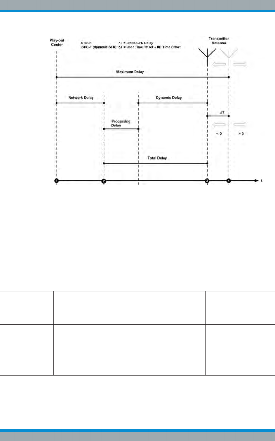
Device View Description
R&S®Tx9
155Operating Manual 2109.9110.02 ─ 07
Fig. 4-6: Delays in SFN
1 = Time of the signal infeed (MIP inserter)
2 = Signal feed at the exciter (Ts x IN)
3 = Regular time of transmission for the station (Tx)
4 = Individually corrected time of transmission for the station (Dispatch Time)
4.6.4.1 Settings
"Time Synchronization" parameters
●Path: "Device View (Home)" > "Tx<n > " > "Exciter A | B" >"SFN Regulation" >
"Time Synchronization"
Name Description Value range Access right
Source The suitable signal source for synchronizing the time of
transmission can be selected in this list.
External
PPS, Internal
GPS
Maintenance
Ext. PPS Indicates whether a seconds pulse is present at the
1PPS_IN socket (X23) at the TCE.
No Signal,
Inaccurate,
OK
Read only
Int. GPS PPS Indicates whether the integrated GPS receiver is
returning a stable seconds pulse (PPS). This function
must have been enabled by installing an option key in
the TCE.
No Signal,
Inaccurate,
OK
Read only
Exciter ATSC

Device View Description
R&S®Tx9
156Operating Manual 2109.9110.02 ─ 07
Name Description Value range Access right
SFN Sync Used to activate time synchronization.
●Off (MFN): The time of transmission is not control-
led.
●Dynamic (SFN): The time of transmission of a
symbol is the same for all the transmitters of a sin-
gle‑frequency network (SFN).
Off (MFN),
Dynamic
(SFN)
Maintenance
SFN Sync Mode Used to define the type of time synchronization. This
switch is available only after the appropriate software
options have been enabled.
●RSMobile: For transmitting mobile content and
when using a Rohde & Schwarz AEM100 Emis-
sion Mux/SFN inserter.
●RSA53: When transmitting normal content and
when using a Rohde & Schwarz AEM100 Emis-
sion Mux/SFN inserter.
●A/110: For standard‑conforming SFN synchroniza-
tion corresponding to ATSC A/110B. It contains a
compatible expansion to allow use of Mobile DTV.
With the synchronization types "R&S Mobile" and "A/
110", a distinction can also be made as to whether the
time of transmission is to be synchronized primarily
using data from the TCP information or using data from
the dummy bytes.
RSMobile,
RSA53,
A/110
Maintenance
PPS State Indicates whether the internally formed PPS is
phase‑synchronized with the frequency control.
●OK: The PPS is phase‑synchronized with the fre-
quency control.
●Holdover: The PPS and the reference frequency of
the frequency control have failed. Time synchroni-
zation is now performed with the accuracy of the
integrated crystal oscillator (OCXO).
●Holdover Expired: The maximum time for which
the transmitter is permitted to remain in holdover
mode has expired (see the Frequency Control
menu).
●Missing: No PPS signal has been detected since
the TCE900 exciter was last started.
If "OK" is not displayed, the signal source of the fre-
quency control must be checked.
OK, Hold-
over, Hold-
over expired,
Missing
Read only
Max. Deviation Used to select the maximum permitted deviation of the
time of transmission relative to the internally controlled
reference frequency. If the set value is exceeded, the
absolute time of transmission is recalculated. This cau-
ses a brief signal failure (mute).
0 s to 100 μsRead only
SFN State Indicates whether or not the fed signal can be transmit-
ted in a time‑synchronous manner. If the "No Time Ref-
erence" fault message is displayed, the reference feed
of the Time Synchronization and the Frequency Regu-
lation must be checked. If the "No Time Information"
fault message is displayed, it must be checked whether
the control information for the time of transmission is
contained in the data stream. (See the "Input" menu.)
SFN Resync,
No Time
Information,
No Time Ref-
erence, SFN
Resync, In
Time
Read only
"SFN Delay" parameters
●Path: "Device View (Home)" > "Tx<n > " > "Exciter A | B" >"SFN Regulation" >
"SFN Delay"
Exciter ATSC

Device View Description
R&S®Tx9
157Operating Manual 2109.9110.02 ─ 07
Name Description Value range Access rights
Maximum Delay Time taken for the signal to travel from the playout cen-
ter to the transmit antenna for regular transmission.
This delay is set at the SFN adapter and is the default
for all transmitters of the dynamic SFN.
0 s to 1 s Read only
Network Delay Time taken for the signal to travel from the playout cen-
ter to the input of the signal processing unit. This delay
depends on the used transmission path. If an IP feed is
used, the FEC processing time is a component of the
Network Delay.
0 s to 1 s Read only
Processing Delay Indicates the internal transit time for signal processing
in the exciter. It depends on the configured modulation
parameters.
0 s to 1 s Read only
Dynamic Delay Indicates the signal delay controlled by the SFN (sin-
gle‑frequency network) synchronization which is
required in order to meet the desired time of transmis-
sion exactly. The displayed value contains the set
Static Delay Offset as well as the Tx Time Offset (if
available).
0 s to 1 s Read only
Total Delay Indicates the total transit time of the signal through the
transmitter. It is the sum of Processing Delay plus
Dynamic Delay.
0 s to 1 s Read only
Static SFN Delay Positive or negative offset (set manually for the individ-
ual transmitter site) of the time of transmission relative
to the regular time of transmission preset under Maxi-
mum Delay. The Static Delay is used to compensate
differences between transmission systems from differ-
ent manufacturers.
0 s to 1 s Maintenance
Dispatch Time Time from the point at which the signal leaves the play-
out center until its actual transmission at the transmit
antenna. This delay corresponds to the Maximum
Delay (compulsory for all transmitters in an SFN) plus
Static Delay Offset plus Tx Time Offset (if available).
0 s to 1 s Read only
4.6.5 Using Frequency Control
The R&S TCE900 in the R&S TCE900 exciter configuration has a transmit frequency
control function.
Depending on the accuracy and stability requirements, one of two operating modes
can be selected for the transmitter.
To operate the transmitter with an integrated GPS receiver, an appropriate software
option must be activated using an option code.
●Free‑wheeling mode
Here the transmit frequency is formed from a temperature‑stabilized 10 MHz crys-
tal oscillator (TCXO).
The frequency stability is sufficient for continuous operation in multiple frequency
networks (MFN).
Exciter ATSC

Device View Description
R&S®Tx9
158Operating Manual 2109.9110.02 ─ 07
●Operation with reference frequency
Here the transit frequency is stabilized by means of a reference frequency. The fol-
lowing options are available:
–External 10 MHz reference frequency
– External PPS (pulse per second)
– Built-in GPS receiver.
The frequency stability and frequency accuracy which can be achieved in this way
fulfill the increased requirements for operation of the transmitter in single‑frequency
networks. If several reference signals are available at the same time, automatic
selection of the most suitable reference frequency is possible.
If the reference signal fails, the transmitter switches over to Holdover Mode and fre-
quency control operates with the accuracy of the temperature‑stabilized 10 MHz crystal
oscillator (OXCO).
Since, in Holdover Mode, frequency control becomes increasingly inaccurate over
time, the output signal of the exciter can be switched off after a configurable Guard
Time.
In the case of reference signals with major fluctuations (jitter), e.g. with non‑controlled
external GPS receivers, a jitter correction function can be activated.
For measuring purposes, the used reference signal or one of the reference signals pro-
cessed internally in the exciter can be output via the Monitor-Out socket (X24).
"Frequency Regulation" parameters
●Path:"Device View (Home)" > "Tx<n>" > "Exciter" > "Frequency Regulation" > Tab
"Frequency Regulation"
Name Description Value range Access right
Ext. 10 MHz (Input) Indicates whether an external 10 MHz reference is
present at the REF_IN (X64) socket on the R&S
TCE900.
No Signal,
Inaccurate,
OK
Read only
Source (Input) The suitable signal source for the frequency reference
can be either detected automatically or preselected in
this list. If multiple signal sources are connected simul-
taneously in "Auto" position, an external reference is
given preference for selection before the internal GPS.
In "Manual" position, the internal crystal oscillator
(OCXO) is calibrated manually and the transmitter can
be operated completely without an external reference
source (not suitable for single-frequency networks).
Manual, Ext.
5 MHz, Ext.
10 MHz, Ext.
PPS, Int.
PPS GPS,
Auto
Read only
Ext PPS (Input) Indicates whether a seconds pulse is present at the
1PPS_IN socket (X23) at the R&S TCE900.
No Signal,
Inaccurate,
OK
Read only
Current Source (input) Shows the signal source used currently for frequency
regulation.
Manual, Ext.
5 MHz, Ext.
10 MHz, Ext.
PPS, Int.
GPS
Read only
Exciter ATSC

Device View Description
R&S®Tx9
159Operating Manual 2109.9110.02 ─ 07
Name Description Value range Access right
Int. GPS PPS (Input) Indicates whether the integrated GPS receiver is
returning a stable seconds pulse (PPS). This function
must have been enabled by installing an option key in
the TCE.
No Signal,
Inaccurate,
OK
Read only
Manual OCXO (regula-
tor)
Enables manual adjustment of the internal crystal oscil-
lator. To allow this, a frequency counter which is
synchronized via a highly accurate reference must be
connected via the monitor output.
0 to 65535 Maintenance
Reference (regulator) Indicates the state of the reference used. In single‑fre-
quency networks, a failure of the reference can cause a
malfunction and thus lead to switchover of the exciter.
Fault, Warn-
ing, OK
Read only
Freq. Stability (regula-
tor)
Indicates the frequency accuracy of the regulator. The
highest possible accuracy ("Excellent") is only reached
at least 24 hours after switching on the exciter. This
ensures that if the reference fails, there are no faults in
single‑frequency networks before the guard time runs
out.
Unknown,
Inaccurate,
Good, Excel-
lent
Read only
Monitor Out (regulator) Used to select the signal to be output at the Monitor
Out socket (X24).
Off, Internal
5 MHz, Inter-
nal 10 MHz,
Internal 1
PPS, Internal
1 PPS GPS,
Current
Source
Operation
On Ref. Fail Mute (reg-
ulator)
Used to define the behavior if the reference source
fails.
●"Never": Muting never takes place. This causes
faults in single‑frequency networks, especially
after power failures.
●"At Startup": After a power failure, muting takes
place until the regulator is synchronized. If the ref-
erence fails, the transmitter will continue running
as long as possible.
●"After Guard Time": Muting takes place not only
after power failures, but also after failure of the ref-
erence and expiry of the set Guard Time.
Never, At
Startup, After
Guard Time
Maintenance
Guard Time (regulator) This value defines for how many hours the signal pro-
cessing should continue running without synchroniza-
tion if the reference connection fails. The Guard Time is
active only if the "Freq Stability" was "Good" at the time
of the failure. The longer the time selected is, the
poorer the accuracy of the transmitting frequency will
become. In addition, the time of transmission of the sig-
nal shifts. If this uses up the guard interval, reception
problems occur in single‑frequency networks.
0 to 24 hours Maintenance
Jitter Correction (Guard
Time)
When using an external reference source with high jit-
ter, activating this function can provide better frequency
stability. With "Good" reference signals, this function
should be disabled as the regulator takes significantly
longer to attain its maximum frequency stability. When
the internal GPS is used, this function is enabled auto-
matically.
On, Off Maintenance
Exciter ATSC

Device View Description
R&S®Tx9
160Operating Manual 2109.9110.02 ─ 07
4.6.6 Precorrection
Each R&S®TCE900 Exciter is equipped with an adaptive precorrector, which continu-
ously compensates for nonlinear distortions of the amplifiers and linear distortions of
the output filter so that, in both cases, a high‑quality signal is present at the output of
the transmitter.
Adaptive nonlinear precorrection
For adaptive nonlinear precorrection, enter a minimum shoulder distance that must not
be undershot. The precorrector will calculate a new precorrection curve as soon as a
shoulder distance below the set value is measured.
The adaptive precorrection can be stopped if necessary (Adaptive Predistortion =
Stop). The current precorrection curve remains in effect.
For measuring purposes, the adaptive nonlinear precorrector can be bypassed (Adap-
tive Predistortion = Bypass) so that the R&S®TCE900 Exciter returns an undistorted
signal at its RF output.
The precorrector can be restarted manually (Reset), making it possible to calculate a
better precorrection curve, even if the shoulder distance has not yet been undershot.
The current precorrection curve is lost as a result.
Adaptive linear precorrection
With adaptive linear precorrection, limit values for amplitude (Amplitude Ripple) and
group delay (Group Delay Ripple) must be set. The precorrector will calculate a new
precorrection curve as soon as the limit values are exceeded.
The adaptive precorrection can be stopped if necessary (Adaptive Predistortion =
Stop). The current precorrection curve remains in effect.
For measuring purposes, the adaptive linear precorrector can be bypassed (Adaptive
Predistortion = Bypass) so that the R&S®TCE900 Exciter returns an undistorted signal
at its RF output.
The precorrector can be restarted manually (Reset), making it possible to calculate a
better precorrection curve, even if the shoulder distance has not yet been undershot.
The current precorrection curve is lost as a result.
The adaptive adjustment of nonlinear precorrection is not available for analog TV
standards.
Crest factor reduction
Available as an option for all COFDM standards
The crest factor feature provides the possibility of improving the signal parameters
"MER" and "Shoulder Distance" separately. Additionally, the signal can be improved
and the DC supply voltage reduced at the amplifier to increase efficiency; this simulta-
neously reduces the crest factor of the transmitter.
Exciter ATSC

Device View Description
R&S®Tx9
161Operating Manual 2109.9110.02 ─ 07
Sound phase shifter
Only available for analog TV standards
The sound phase shifter modifies the phase of the sound subcarrier as a function of
the low-frequency modulation of the picture signal.
When the sound phase shifter is switched on, its characteristic is determined using two
onset points.
The reference for setting the position is initially a value of 37.5 % for the back porch.
Smaller values are in the range of the sync pulse, whereby a value of 15 % corre-
sponds to a sync‑pulse amplitude of 300 mV. Larger values are in the picture range,
whereby a value of 90 % corresponds to a picture amplitude of 700 mV.
An additional condition is that the setting for onset point 1 must always be greater than
that of onset point 2. The sharpness of the two onset points is determined by the slope
of the characteristic at these points. The magnitude of the setting determines the mag-
nitude of the phase shift, whereby a setting of 50 % specifies the maximum value. The
sign of the setting value determines whether the phase is shifted in the positive or neg-
ative direction.
When the characteristic is calculated, it is divided into three linear areas by the two
onset points.
No phase shift takes place for modulation of the picture signal in the area between the
two onset points, i.e. a correction phase of 0° is set.
A correction phase unequal to 0° is set in the case of picture signal modulation which is
greater than the position of onset point 1. The characteristic in this area begins with a
correction phase of 0°, with modulation corresponding to the position of onset point 1,
and increases linearly up to the maximum phase set with slope 1, with 100 % modula-
tion of the picture signal.
Similarly, a correction phase unequal to 0° is also set in the case of picture signal mod-
ulation which is smaller than the position of onset point 2. The characteristic in this
area begins with a correction phase of 0°, with modulation corresponding to the posi-
tion of onset point 2, and increases linearly up to the maximum phase set with slope 2,
with 0 % modulation of the picture signal.
"Non Linear" parameters
●Path:Device View (Home) > Transmitter > Exciter > Pre-Correction > Non Linear
Exciter ATSC

Device View Description
R&S®Tx9
162Operating Manual 2109.9110.02 ─ 07
Name Description Value range Access right
Adaptive Precor-
rection (Settings)
The nonlinear precorrector is used to compensate amplifier faults. The
quality of precorrection affects the shoulder distance of the output sig-
nal.
The setting can be changed here.
●Bypass
The nonlinear precorrector is deactivated. The signal is not modi-
fied inside the exciter.
●Stop
Adaptive precorrection is deactivated. The correction curve that
was determined last is active inside the exciter.
●Run
Digital TV standards only: The adaptive precorrector is active.
The best possible precorrection curve to compensate amplitude
and phase errors of the amplifiers is determined continuously.
Analog TV standards only: The automatic precorrector is active.
The best possible precorrection curve to compensate amplitude
and phase errors of the amplifiers is determined once. The pre-
corrector then enters "Stop" mode. The program is interrupted
during precorrection.
In certain situations, it may be advisable to have a suitable precorrec-
tion curve determined automatically first and then to switch adaptive
precorrection to "Stop" so that the found precorrection curve can no
longer change.
Calculation of a new precorrection curve can be forced by performing
a reset.
Bypass, Stop,
Run
Maintenance
Status (Settings) Indicates the status of the nonlinear precorrector.
●Idle
The precorrector is not active.
●Acquisition
The precorrector is currently recording new measurement values.
●Calculation
The precorrector is currently calculating a new precorrection
curve.
Idle, Acquisition,
Calculation
Read Only
Input Level (Set-
tings)
Indicates whether the level of the input signal is sufficient. "No Input"
appears if the transmitter is off or if the connection to the RF test point
is interrupted.
OK, Too Low,
Too High, No
Input
Read Only
Reset (Settings) Resets the precorrection. If the precorrector is in "run" mode, a new
precorrection curve is calculated.
Maintenance
Shoulder Distance
(Shoulders)
Indicates the minimum shoulder distance that is to be achieved by the
adaptive nonlinear precorrector.
The setting can be changed here.
The precorrector will calculate a new precorrection curve as soon as a
shoulder distance below the set value is measured.
30 dB to 45 dB Maintenance
Shoulder Left
(Shoulders)
Indicates the shoulder distance attained by the circuit for automatic
switchover, measured in the left part of the signal spectrum.
Read Only
Shoulder Right
(Shoulders)
Indicates the shoulder distance attained by the circuit for automatic
switchover, measured in the right part of the signal spectrum.
Read Only
Signal Limiter
(Limiter)
Limits the signal at the input of the nonlinear precorrector.
The setting can be changed here.
6 dB to 12 dB Maintenance
Exciter ATSC

Device View Description
R&S®Tx9
163Operating Manual 2109.9110.02 ─ 07
"Linear" parameters
●Path:Device View (Home) > Transmitter > Exciter > Pre-Correction > Linear
Name Description Value range Access right
Adaptive Precor-
rection (Settings)
The linear precorrector is used to compensate output filter faults. The
quality of precorrection affects the amplitude and group delay ripple of
the output signal.
The setting can be changed here.
●Bypass
The linear precorrector is deactivated. The signal is not modified
inside the exciter.
●Stop
Adaptive precorrection is deactivated. The correction curve that
was determined last is active inside the exciter.
●Run
Digital TV standards only: The adaptive precorrector is active.
The best possible precorrection curve to compensate for ampli-
tude and group delay errors caused by the output filter is deter-
mined continuously.
Analog TV standards only: The automatic precorrector is active.
The best possible precorrection curve to compensate for ampli-
tude and group delay errors caused by the output filter is deter-
mined once. The precorrector then enters "Stop" mode. The pro-
gram is interrupted during precorrection.
In certain situations, it may be advisable to have a suitable precorrec-
tion curve determined automatically first and then to switch adaptive
precorrection to "Stop" so that the found precorrection curve can no
longer change.
Bypass, Stop,
Run
Maintenance
Status (Settings) Indicates the status of the linear precorrector.
●Idle
The precorrector is not active.
●Acquisition
The precorrector is currently recording new measurement values.
●Calculation
The precorrector is currently calculating a new precorrection
curve.
Idle, Acquisition,
Calculation
Read Only
Input Level (Set-
tings)
Indicates whether the level of the input signal is sufficient. "No Input"
appears if the transmitter is off.
OK, Too Low,
Too High, No
Input
Read Only
Slope (Settings) Indicates the asymmetry compensation caused by the RF cable used
between the RF test point downstream of the output filter and the input
of the linear precorrector.
The setting can be changed here.
-1 dB to 1 dB Maintenance
Reset (Settings) Resets the precorrection. If the precorrector is in "run" mode, a new
precorrection curve is calculated.
Maintenance
Amplitude Ripple
Limit (Amplitude
Ripple Limiter)
Indicates the desired maximum amplitude ripple at the output of the fil-
ter. If the circuit for automatic switchover is switched on, the precorrec-
tor attempts to modify the signal to such an extent that the amplitude
ripple remains below the specified limit.
The setting can be changed here.
0 dB to 2 dB Maintenance
Exciter ATSC

Device View Description
R&S®Tx9
164Operating Manual 2109.9110.02 ─ 07
Name Description Value range Access right
Amplitude Ripple
(Amplitude Ripple
Limiter)
Indicates whether the limit set for the amplitude ripple can be achieved
by the linearity corrector.
If the limit was chosen too low, a warning is displayed. In this case, the
corrector will retain the last-calculated curve.
Limit OK, limit
unreachable
Read Only
Amplitude Ripple
(Amplitude Ripple
Limiter)
Indicates the residual ripple in the amplitude frequency response
attained by the circuit for automatic switchover in dB.
Read Only
Group Delay Limit
(Group Delay Lim-
iter)
Indicates the desired maximum group delay ripple at the output of the
filter. If the circuit for automatic switchover is switched on, the precor-
rector attempts to modify the signal to such an extent that the group
delay ripple remains below the specified limit.
The setting can be changed here.
10 ns to 500 ns Maintenance
Group Delay
(Group Delay Lim-
iter)
Indicates whether the limit set for the group delay can be achieved by
the linearity corrector.
If the limit was chosen too low, a warning is displayed. In this case, the
corrector will retain the last-calculated curve.
Limit OK, limit
unreachable
Read Only
Group Delay Rip-
ple (Group Delay
Ripple)
Indicates the residual ripple in the group delay attained by the circuit
for automatic switchover in ns.
Read Only
"Crest Factor" parameters
Available as an option for all COFDM standards
●Path:Device View (Home) > Transmitter > Exciter > Pre-Correction > Crest Factor
Name Description Value range Access right
Reduction Activates manual crest factor reduction. This function is used to opti-
mize the efficiency of the transmitter.
●Bypass
Deactivates the crest factor reduction.
●Manual
Activates manual crest factor reduction.
Bypass, Manual Maintenance
Crest Factor Used to set the crest factor of the exciter's output signal. Setting a low
crest factor allows the efficiency of the transmitter to be increased as a
result of the lower operating voltage of the amplifiers. This can lead to
an increase in intermodulation products outside the frequency band
and to a reduction in MER.
7 dB to 15 dB Maintenance
Inband Noise Increasing this value results in a lower crest factor. This, however,
reduces MER.
10% to 100% Maintenance
Outband Noise Increasing this value produces a lower crest factor; however, this
results in an increase in intermodulation products outside the fre-
quency band.
0% to 50% Maintenance
"Advanced Precorrection" parameters
Available for analog TV standards
●Path:Device View (Home) > Transmitter > Exciter > Pre-Correction > Advanced
Precorrection
Exciter ATSC

Device View Description
R&S®Tx9
165Operating Manual 2109.9110.02 ─ 07
Name Description Value range Access right
Test Signal (Non-
linear Extension)
Generates signals with different modulation in order to increase the
video S/N ratio using an external measuring instrument. Measurement
of the video S/N ratio and adjustment of the associated slopes allows
the S/N ratio to be optimized for various picture contents.
Black, Grey,
White, Off
Maintenance
Black Slope
(Nonlinear Exten-
sion)
Used to optimize the video S/N ratio at high levels.
The value can only be changed if the nonlinear precorrector is in
"Stop" mode and the test signal "Black" has been activated.
-50% to 50% Maintenance
Grey Slope (Non-
linear Extension)
Used to optimize the video S/N ratio at medium levels.
The value can only be changed if the nonlinear precorrector is in
"Stop" mode and the test signal "Grey" has been activated.
-50% to 50% Maintenance
White Slope
(Nonlinear Exten-
sion)
Used to optimize the video S/N ratio at low levels.
The value can only be changed if the nonlinear precorrector is in
"Stop" mode and the test signal "White" has been activated.
-50% to 50% Maintenance
Phase Correction
(FM Carrier 1/2)
Indicates whether the sound phase shifter for carrier 1 and carrier 2 is
switched on.
The setting can be changed here.
Off, On Maintenance
Trigger Point 1/2
(FM Carrier 1/2)
Indicates the position defined for the respective onset point of the
phase shifter (referenced to modulation of the picture signal).
The setting can be changed here.
0% to 100% Maintenance
Slope 1/2 (FM
Carrier 1/2)
Indicates the value that has been set for the slope at the respective
onset point of the phase shifter.
The setting can be changed here.
-50% to 50% Maintenance
4.7 Exciter DTMB
4.7.1 Coder for DTMB
To operate the transmitter in DTMB mode, an appropriate software option must be acti-
vated using an option key.
The DTMB transmission parameters required for coding and modulation as well as the
TPS settings (TPS = transmission parameter signaling) used and signaled during
transmission can be checked in the "Config" and "Modulation" menu fields.
The DTMB standard can be used both in single frequency networks (SFN) and multiple
frequency networks (MFN). In SFNs, the TPSs are usually set automatically by the
megaframe information packet (MIP) or second frame initialization packet (SIP); in
MFNs, the TPS parameters are usually set manually.
Exciter DTMB

Device View Description
R&S®Tx9
207Operating Manual 2109.9110.02 ─ 07
Name Description Value range Access right
Guard Time (regulator) This value defines for how many hours the signal pro-
cessing should continue running without synchroniza-
tion if the reference connection fails. The Guard Time is
active only if the "Freq Stability" was "Good" at the time
of the failure. The longer the time selected is, the
poorer the accuracy of the transmitting frequency will
become. In addition, the time of transmission of the sig-
nal shifts. If this uses up the guard interval, reception
problems occur in single‑frequency networks.
0 to 24 hours Maintenance
Jitter Correction (Guard
Time)
When using an external reference source with high jit-
ter, activating this function can provide better frequency
stability. With "Good" reference signals, this function
should be disabled as the regulator takes significantly
longer to attain its maximum frequency stability. When
the internal GPS is used, this function is enabled auto-
matically.
On, Off Maintenance
4.11 Switchless Combiner
The switchless combiner couples the RF output signals of two racks and feeds the total
power to the antenna. If a rack has a power drop, the switchless combiner ensures
maximum output power at the antenna by a continuous shift of the phase angle.
Operating principle
The switchless combiner consists of two 90-degree couplers and an RF tube of varia-
ble length (referred to as a trombone). Changing the length makes it possible to gener-
ate a variable phase shift between the two inputs. If there is a complete power drop at
an input, the power of the other input can be fed to the antenna without loss. If there is
a partial power drop at one of the two inputs, the power dissipation in the absorber is
minimized by adjusting the phase angle.
Commissioning
During commissioning, the position of the trombone has to be calibrated for different
phase angles. To do so, connect an external power meter to the absorber of the
switchless combiner.
The calibration process consists of the following work steps:
●Start the calibration process.
●Set the switchless combiner to "local".
●Switch the signal of input 1 off.
●Press the up/down buttons on the switchless combiner to set the trombone so that
the power dissipation at the absorber is minimal.
●Press "Save Position".
●Switch the signal of input 1 on and of input 2 off.
●Press the up/down buttons on the switchless combiner to set the trombone so that
the power dissipation at the absorber is minimal.
Switchless Combiner

Device View Description
R&S®Tx9
208Operating Manual 2109.9110.02 ─ 07
●Press "Save Position" again.
●Switch the signal of input 2 back on.
●End the calibration process and set the switchless combiner to "remote".
Finally, use the phase shifter in rack 2 to set a power maximum at the antenna.
The calibration process has to be carried out again after changing the frequency. In
addition, the switchless combiner has to be reprogrammed beforehand according to
the manufacturer's instructions.
Operation
In "Automatic" mode, the switchless combiner responds to power losses at its inputs
independently. In "Manual" mode, one of three fixed positions of the trombone can be
moved to, for example, to switch off a rack.
4.11.1 Settings
"Overview" parameters
●Path: "Device View (Home)" > "Tx<n >" > "Output Stage" >"Switchless Combiner"
> "Overview"
Name Description Value range Access right
Automatic (Control) Switches the automatic power control of the rack
combiner on and off.
Off, On Maintenance
Position (Control) Indicates which input was switched to the antenna
when automatic is switched off.
The setting can be changed here.
1, 2, 1+2 Read only
Current Position (Regu-
lation)
Indicates the current effective phase angle between the
two inputs. If the coupling is symmetric, the phase
angle is 90 degrees. If the switchless combiner has not
yet been calibrated for the current transmitter fre-
quency, the display shows a %.
0 degrees to
180 degrees,
0 % to 100 %
Read only
Status (Regulation) Indicates whether the control is currently working:
●Hold: The phase angle is constant.
●Phase decreasing/Phase increasing: The phase
angle is currently being changed.
Hold, Phase
decreasing,
Phase
increasing
Read only
Calibration (Regulation) Indicates whether the switchless combiner has been
calibrated for the current transmitter frequency.
●OK: The switchless combiner is calibrated.
●Warning: The switchless combiner has not yet
been calibrated.
Ok, Warning Read only
Access (Device Status) Indicates whether the switchless combiner is in "Local"
mode or "Remote" mode. For the control to work, the
switchless combiner has to be in "Remote" mode.
Local/
Remote
Read only
Switchless Combiner

Device View Description
R&S®Tx9
209Operating Manual 2109.9110.02 ─ 07
Name Description Value range Access right
Link (Device Status) Indicates whether there are data communications
between the transmitter and switchless combiner.
SFN Resync,
No Time
Information,
No Time Ref-
erence, SFN
Resync, In
Time
Read only
Warning (Device Sta-
tus)
Indicates whether the switchless combiner signals a
warning. This indication is identical to the indication on
the control panel of the switchless combiner.
Off, Yes Read only
Fault (Device Status) Indicates whether the switchless combiner signals an
error. This indication is identical to the indication on the
control panel of the switchless combiner.
Off, Yes Read only
RF Probe (Device Sta-
tus)
Indicates whether the test point at the antenna output
functions.
OK, Fail Read only
RCB (Device Status) Indicates whether the redundancy control board in the
R&S TCE900 system control functions without errors.
OK, Fail Read only
"Calibration" parameters
●Path: "Device View (Home)" > "Tx<n >" > "Output Stage" >"Switchless Combiner"
> "Calibration"
Name Description Value range Access right
Calibration (Calibration) Starts the calibration process. The calibration steps to
be carried out are displayed in the "Instruction" field
after the calibration process has been started.
Off, On Maintenance
Save Position (Calibra-
tion)
Saves the upper or lower position of the trombone dur-
ing the calibration process.
Maintenance
Forward Power (Cali-
bration)
Indicates the power at the antenna. 0 kW to
100 kW
Read only
Transmitter (Calibra-
tion)
Indicates whether the transmitter is switched on.
The setting can be changed here.
Off, On Maintenance
Instruction (Calibration) Indicates the next step after starting the calibration
process.
Read only
Rack 1-4 (Calibration) Indicates whether the respective rack is switched on.
During the calibration process, the RF at the inputs of
the switchless combiner can be switched off using this
switch.
Auto/Off Maintenance
Access Combiner (Sta-
tus)
Indicates whether the switchless combiner is in "Local"
mode or "Remote" mode. For the control to work, the
switchless combiner has to be in "Remote" mode
Local/
Remote
Read only
Status (Status) Indicates whether the switchless combiner has been
calibrated for the current transmitter frequency.
Calibrated,
Uncalibrated
Read only
Switchless Combiner
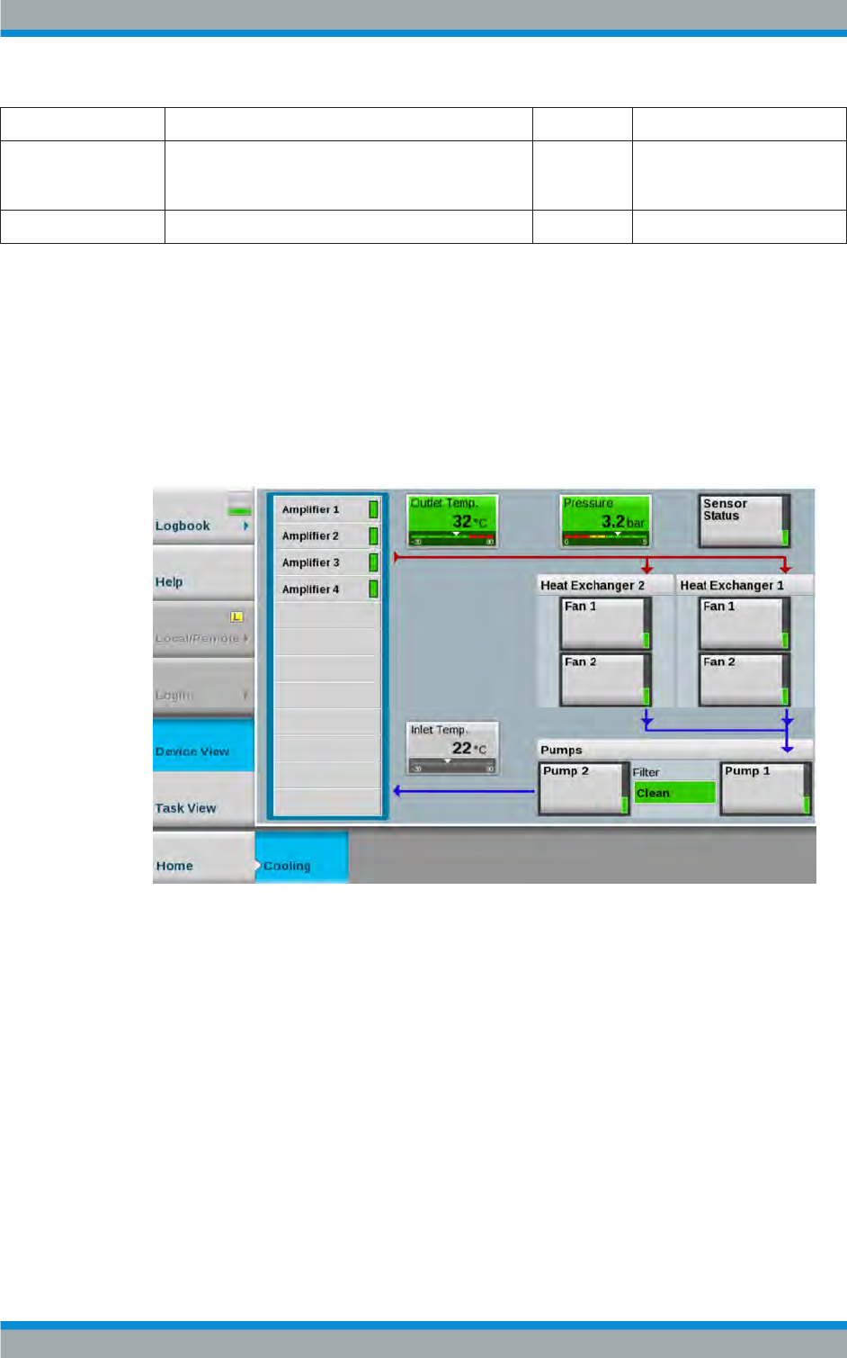
Device View Description
R&S®Tx9
210Operating Manual 2109.9110.02 ─ 07
Name Description Value range Access right
Position (degree) (Sta-
tus)
Indicates the currently set phase angle. This display is
available only if the switchless combiner has been cali-
brated.
0 degrees to
180 degrees
Read only
Position (raw) (Status) Indicates the position of the trombone (unitless). 0 to 1024 Read only
4.12 Cooling System
4.12.1 Liquid Cooling (High‑Performance)
The following illustration shows the "Cooling" menu for liquid cooling.
4.12.1.1 Configuring Switching Thresholds (Pressure) and Flow Volumes
●Path:Device View (Home) > Cooling
Cooling System

Device View Description
R&S®Tx9
211Operating Manual 2109.9110.02 ─ 07
Name Description Value range Access right
Type A distinction must be made between the following types:
●R&S Standard
If the transmitter is connected to a 9000 series cooling sys-
tem, select "R&S Standard".
●If the transmitter is connected to an existing site cooling
system, select the "Site Cooling" setting. In this case,
warning and fault signaling lines which are routed to termi-
nal x8000 of the mains distribution board (MDB) are evalu-
ated.
●If an FM single transmitter is connected to a simplified
cooling system without temperature control, select the
"R&S Small" setting.
R&S Standard,
Site Cooling,
R&S Small
Configuration
Heat Exchangers /
Rack
Either 1 or 2 redundant heat exchangers can be used in each
rack. The set value affects fan monitoring and also the indica-
tors on the user interface.
1 or 2 Configuration
Fans / Heat
Exchanger
Either 1 or 2 fans can be used for each heat exchanger. The set
value affects fan monitoring and also the indicators on the user
interface.
0, 1 or 2 Configuration
Set Point Tempera-
ture
At this temperature, the temperature control system will attempt
to adjust the coolant temperature by changing the fan speed at
the heat exchangers. If the temperature drops below or
exceeds the control range, the actual coolant temperature can
be higher or lower.
25 to 65 Configuration
Fault Limit (Coolant
Temperature)
If the coolant temperature exceeds this value, a fault is trig-
gered and the rack is shut down. In N+1 systems, this event
can lead to switchover of the transmitter.
50 to ‒65 Configuration
Warning Limit (Cool-
ant Temperature)
If the coolant temperature exceeds this value, a warning is trig-
gered. The fault threshold is permanently set to 65 °C.
40 to 65 Configuration
(Coolant Pressure)
Warning Limit
If the coolant pressure drops to this value or lower, a warning is
triggered. Normally, this value should be set higher than the
value for the corresponding "Fault Limit".
0 to 4 Configuration
(Coolant Pressure)
Fault Limit
If the coolant pressure drops to this value or lower, a fault is
triggered. Normally, this value should be lower than the value
for the corresponding "Warning Limit".
0 to 4 Configuration
Max Fan Speed If necessary, the maximum speed of the fans at the heat
exchanger can be decreased in order to reduce noise. This can,
however, result in an increase in coolant temperature or even in
shutdown of the transmitter.
50 % to 100 % Configuration
If Temperature
Exceeds Warning
Limit (Fans)
If a speed limit has been activated for the fans, this switch can
be used to select how the cooling system is to respond if the
warning threshold for the return temperature is exceeded.
●"Keep Fans Quiet"
The speed limit for the fans remains activated. The trans-
mitter is shut down when the fault threshold for the return
temperature is reached.
●"Rise Noise Level of Fans"
The set speed limit for the fans is deactivated and the fan
speed is automatically increased to max. 100 % of the
nominal speed.
Keep Fans
Quiet
1 = Rise Noise
Level of Fans
Configuration
Cooling System

Device View Description
R&S®Tx9
212Operating Manual 2109.9110.02 ─ 07
Name Description Value range Access right
If Temperature
Exceeds Warning
Limit (RF)
Automatic reduction of the output power can be performed in
order to reduce the temperature level of cooling when the warn-
ing threshold is exceeded. In this case, the amplifiers are auto-
matically precorrected corresponding to their lower power.
Keep Nominal
RF Power
Reduce RF
Power to 80 %
Reduce RF
Power to 60 %
Configuration
Extra Flow Rate In addition to the minimum flow rate predetermined by the num-
ber of amplifiers, the flow can be increased in two stages if
additional components which require cooling (e.g. dummy load)
are installed.
0
+10
+20
Configuration
Hide Pump Errors During registration of pumps on the pump bus, this switch can
be used to hide fault messages which could otherwise cause
the transmitter to shut down. This makes it possible to discon-
nect pumps from the bus without interrupting operation.
Off
On
Maintenance
Hide Fan Errors During registration of fans on the fan bus, this switch can be
used to hide fault messages which could otherwise cause the
transmitter to shut down. This makes it possible to disconnect
fans from the bus without interrupting operation. The switch
acts on all fans of an output stage.
Off
On
Maintenance
Site Cooling Warning Warnings from the site cooling system are displayed here. This
message only functions if the appropriate signals from the site
cooling system are supplied via terminal x8000 of the mains
distribution board (MDB).
OK
Warning
Read only
Site Cooling Fault Faults at the site cooling system are displayed here. This mes-
sage only functions if the appropriate signals from the site cool-
ing system are supplied via terminal x8000 of the mains distri-
bution board (MDB).
OK
Fault
Read only
Pump (State) Indicates whether the pump has been correctly registered on
the pump communication bus by the transmitter control unit.
Not Found
Installed
Read only
Motor (State) Indicates whether the pump motor can run freely or is mechani-
cally blocked. To rectify this fault, the pump must be disassem-
bled and checked for foreign objects.
Blocked
OK
Read only
Operating Hours
(Pump)
Indicates how long the pump has been in operation. 0 to 999999 Read only
(Pump) Type Indicates the used pump type. The displayed type is identical to
the type specified on the type plate of the pump.
●The type "40‑100" should be used for transmitters with up
to 6 amplifiers.
●The type "32‑120" should be used for transmitters with
more than 6 amplifiers.
"40‑100",
"32‑120"
Read only
Flow Indicates the currently measured flow through the pump. 0 to 200 Read only
Speed Indicates the currently measured speed of the pump motor. 0 to 100
Fan (State) Indicates whether the assigned fan is correctly registered on the
fan communication bus.
not found
installed
Read only
(Fan) Motor Indicates whether the fan motor is ready for operation or is
mechanically blocked.
Blocked
OK
Read only
Cooling System

Device View Description
R&S®Tx9
213Operating Manual 2109.9110.02 ─ 07
Name Description Value range Access right
(Fan) Supply If this message appears, the fan is disconnected from the
power supply.
Check the position of the maintenance switch on the heat
exchanger; also check the circuit breaker of the fan in the mains
distribution unit of the rack.
OK
Failure
Read only
Inlet Temp. Indicates the temperature of the coolant flowing into the trans-
mitter rack.
‒30 °C to
+90 °C
Read only
Outlet Temp. Indicates the temperature of the coolant flowing out of the trans-
mitter rack toward the heat exchanger. The temperature must
not exceed a maximum value of 65 °C.
‒30 °C to
+90 °C
Read only
Pressure Indicates the pressure of the coolant. With the pumps switched
off, this pressure can be slightly lower than when the pumps are
running. The correct pressure depends on the delivery head of
the pumps, the temperature of the coolant and the altitude of
the operating location.
Precise pressure tables can be found in the manual.
0 to 6 Read only
Antifreeze Used to define whether or not the fans at the heat exchanger
are to switch off if the temperature drops well below the speci-
fied temperature. Off: The fans switch off. This setting is recom-
mended in order to reduce the energy consumption of the cool-
ing system. On: The fans continue to run even at low outside
temperatures. This setting is recommended if the risk of fan
seizure due to freezing is to be reduced. Note: Even if anti-
freeze mode is active, the condensation protection function of
the transmitter will still switch off the fans at an inlet tempera-
ture below approx. +10 °C. The fans are designed in such a
way that they are not damaged if they seize up due to freezing.
Off; On Configuration
Auto/On If the switch is set to "On", the cooling system is switched on
irrespective of whether or not the transmitter is on. This setting
should only be used when putting the system into operation. If
the switch is set to "Auto", the cooling system is switched on/off
when the transmitter is switched on/off.
Cooling is
always On;
Cooling is
switched on by
Parameter "On"
Configuration
4.12.1.2 Configuring Fans and Pumps
The settings for fans are made in the following way:
For a standard cooling system with one transmitter rack, one pump unit and one heat
exchanger, configuration is performed automatically. Manual configuration is only nec-
essary in the following cases:
●More than one rack
●More than one heat exchanger per rack
1. Ensure that no pumps and fans are connected to the mains distribution board
(MDB).
2. Press the following buttons: Task View > Setup Cooling > Scan Devices.
3. In the Scan Control field, switch Scan Device to "On".
Cooling System

Device View Description
R&S®Tx9
214Operating Manual 2109.9110.02 ─ 07
4. Follow the dialog step by step by connecting one fan after the other and one pump
after the other in the specified sequence to the mains distribution board (MDB) on
the rear of the transmitter rack.
Note: The status of this process is signaled by the status display in the Scan Con-
trol field:
●off (gray) = Scan Devices is switched off.
● In progress (yellow) = configuration is running
● Finished (green) = configuration has been successfully completed; all displays
in the Rack 1 and Rack 2 fields are set to Nothing to do.
5. Switch Scan Device to "Off".
4.12.1.3 Status of Cooling System
Cooling status parameters
Name Description Value range Access right
Sensor for inlet temper-
ature
Indicates the status of the temperature sensor at the
inlet of the rack. If a fault is indicated, first check the
connecting cable between the sensor and the cooling
interface card in the R&S TCE900 system control unit.
Green: OK
Red: Sensor
Fault
Read only
Sensor for outlet tem-
perature
Indicates the status of the temperature sensor at the
outlet of the rack.
Green: OK
Red: Sensor
Fault
Read only
Sensor for coolant
pressure
Indicates the status of the pressure sensor. If a fault is
indicated, first check the connecting cable between the
sensor and the cooling interface card in the
R&S TCE900 system control unit.
Green: OK
Red: Sensor
Fault
Read only
Status of coolant filter Indicates that the pump power is not sufficient to
deliver the required flow. With a correctly dimensioned
and installed cooling system, this only occurs if the
coolant filter is blocked.
Green: OK
Yellow: Filter
Warning
Read only
Sensor for overall sta-
tus
Indicates whether the temperature sensors and pres-
sure sensor are OK. A malfunction at the pressure sen-
sor results in a fault; a malfunction at a temperature
sensor results in a warning.
Green: OK
Yellow:
Warning
Red: Fault
Read only
4.12.2 Small Cooling – Simplified Liquid Cooling System (FM Transmitter)
The following illustration shows the "Cooling" menu for "Small Cooling".
Cooling System
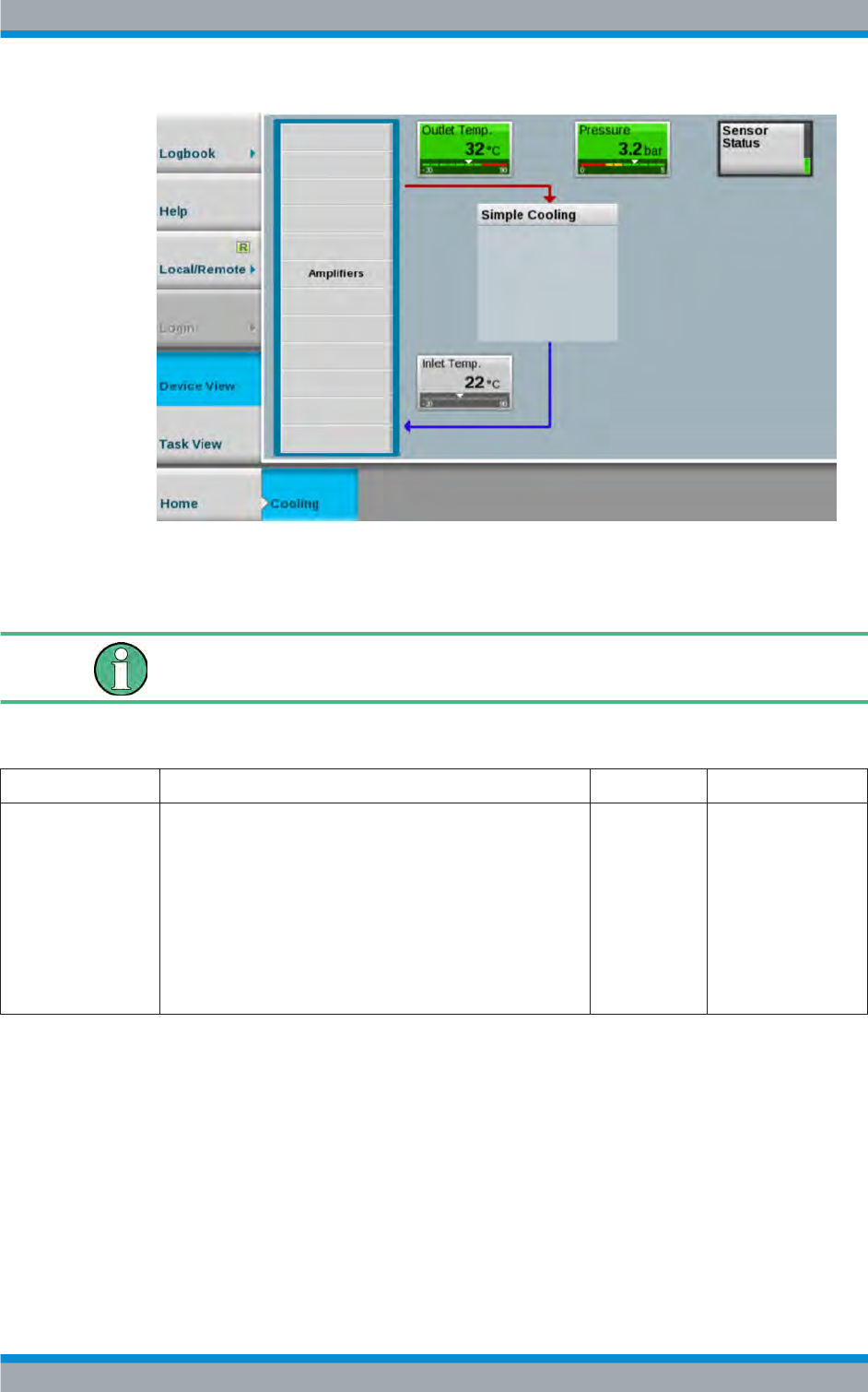
Device View Description
R&S®Tx9
215Operating Manual 2109.9110.02 ─ 07
4.12.2.1 Configuration of Cooling System
The "Small Cooling" mode (simplified cooling) is used only for FM single transmitters.
●Path:Device View (Home) > Cooling > Task View > Setup Cooling
Name Description Value range Access right
Type The following cooling system types can be configured:
●R&S Standard
If the transmitter is connected to a 9000 series cooling sys-
tem, select the "R&S Standard" setting.
●Site Cooling
Set this configuration if the FM transmitter system is to be
connected to the existing site cooling system.
●R&S Small
If an FM single transmitter is connected to a simplified
cooling system without temperature control, use the
"R&S Small" setting.
R&S Standard,
Site Cooling,
R&S Small
Configuration
4.12.2.2 Status
●Path:Device View (Home) > Cooling
Pressing the buttons
●Outlet Temp.
●Pressure
●Sensor Status
●Inlet Temp.
Cooling System

Device View Description
R&S®Tx9
216Operating Manual 2109.9110.02 ─ 07
switches to the "Sensors" view or tab.
"Sensors" parameters
Name Description Value range Access right
Outlet Temp.
(Outlet Tempera-
ture)
Indicates the temperature of the coolant flowing out of the transmitter
rack toward the heat exchanger. The temperature must not exceed a
maximum value of 65 °C.
‒30 °C to +90 °C Read only
Sensor Status
(Outlet Tempera-
ture)
Indicates the status of the temperature sensor at the outlet of the rack. Off, Sensor Fault,
OK
Read only
Warning Limit
(Outlet Tempera-
ture)
Indicates the threshold value for a temperature warning.
If the coolant temperature exceeds this value, a warning is triggered.
The threshold value can be set here (in steps of 1 degree).
40 °C to 65 °C Configuration
Fault Limit (Outlet
Temperature)
Indicates the threshold value for displaying a temperature fault.
If the coolant temperature exceeds this value, a corresponding temper-
ature fault is displayed and the rack is shut down. In N+1 systems, this
event can lead to switchover of the transmitter.
The threshold value can be set here (in steps of 1 degree).
50 °C to 65 °C Configuration
Inlet Temp. (Inlet
temperature)
Indicates the temperature of the coolant flowing into the transmitter
rack.
‒30 °C to +90 °C Read only
Sensor Status
(Inlet Tempera-
ture)
Indicates the status of the temperature sensor at the inlet of the rack.
If a fault is indicated, first check the connecting cable between the sen-
sor and the cooling interface card (CIF) in the R&S TCE900 system
control unit.
Off, Sensor Fault,
OK
Read only
Pressure (Cool-
ant Pressure)
Indicates the pressure of the coolant.
With the pumps switched off, this pressure can be slightly lower than
when the pumps are running. The correct pressure depends on the
delivery head of the pumps, the temperature of the coolant and the alti-
tude of the operating location. Precise pressure tables can be found in
the system manual for the transmitter.
‒500 Pa to
+500 Pa
Read only
Sensor Status
(Coolant Pres-
sure)
Indicates the status of pressure sensor 1. If a fault is indicated, first
check the connecting cable between the sensor and the air cooling
interface card in the R&S TCE900 system control unit.
Off, Sensor Fault,
OK
Read only
Warning Limit
(Coolant Pres-
sure)
Indicates the threshold value for a pressure warning.
If the coolant pressure drops to this value or lower, a warning is trig-
gered. This value should be set higher than the value for the corre-
sponding "Fault Limit".
The threshold value can be set here (in steps of 1 bar).
0.0 bar to 4.0 bar Configuration
Fault Limit (Cool-
ant Pressure)
Indicates the threshold value for displaying a pressure fault.
If the coolant pressure drops to this value or lower, a corresponding
pressure fault is displayed. This value should be set lower than the
value for the corresponding "Warning Limit".
The threshold value can be set here (in steps of 1 bar).
0.0 bar to 4.0 bar Configuration
Cooling System
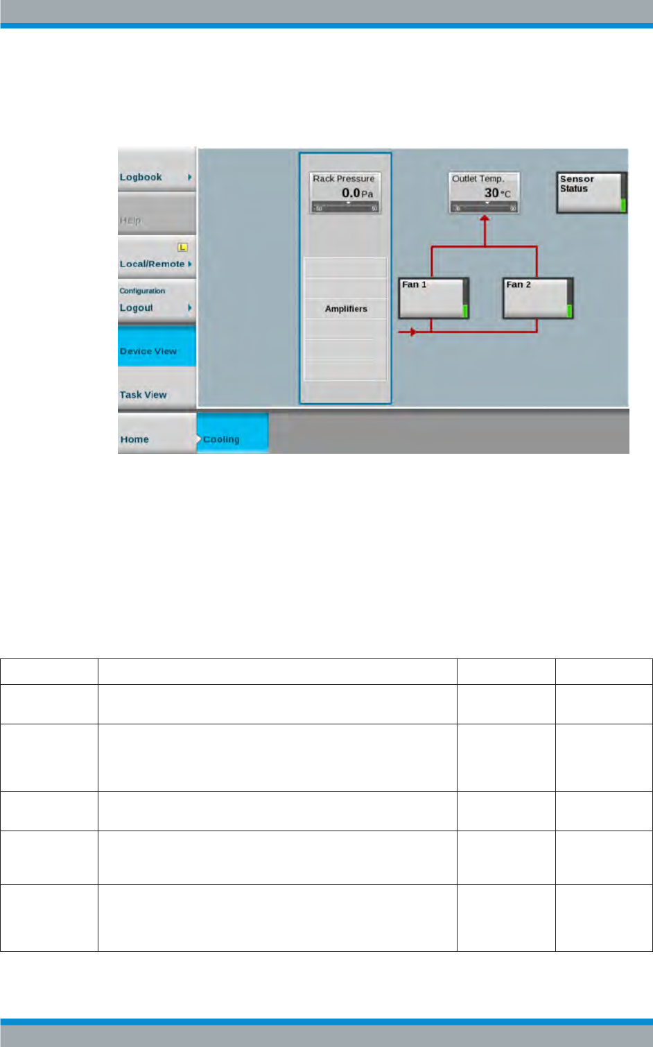
Device View Description
R&S®Tx9
217Operating Manual 2109.9110.02 ─ 07
4.12.3 Air Cooling (Medium‑Power)
The following illustration shows the "Cooling" menu for air cooling.
●Path:Device View (Home) > Cooling
Pressing the buttons
●Rack Pressure
●Outlet Temp.
●Sensor Status
switches to the "Sensors" view or tab.
"Sensors" parameters
Name Description Value range Access right
Inlet Temperature Indicates the temperature of the air flowing into the transmitter rack
(only for ducted intake air with an optional intake air kit).
‒30 °C to +90 °C Read only
Sensor Status
(Inlet Tempera-
ture)
Indicates the status of the temperature sensor at the inlet of the rack. If
a fault is indicated, first check the connecting cable between the sen-
sor and the air cooling interface in the R&S TCE900 system control
unit (only for ducted intake air with an optional intake air kit).
Off, Sensor Fault,
OK
Read only
Outlet Tempera-
ture
Indicates the temperature of the air flowing out of the transmitter rack. ‒30 °C to +90 °C Read only
Sensor Status
(Outlet Tempera-
ture)
Indicates the status of the temperature sensor at the outlet of the rack. Off, Sensor Fault,
OK
Read only
Rack Pressure Indicates the pressure in the rack. Two differential pressure sensors
(Sensor 1 and Sensor 2) measure the differential air pressure inside
and outside the rack. If a sensor fails, the remaining sensor continues
to indicate the pressure inside the rack.
‒500 Pa to
+500 Pa
Read only
Cooling System

Device View Description
R&S®Tx9
218Operating Manual 2109.9110.02 ─ 07
Name Description Value range Access right
Sensor 1 (Pres-
sure 1)
Indicates the status of pressure sensor 1. If a fault is indicated, first
check the connecting cable between the sensor and the air cooling
interface card in the R&S TCE900 system control unit.
Off, Sensor Fault,
OK
Read only
Sensor 2 (Pres-
sure 2)
Indicates the status of pressure sensor 2. If a fault is indicated, first
check the connecting cable between the sensor and the air cooling
interface card in the R&S TCE900 system control unit.
Off, Sensor Fault,
OK
Read only
"Status Fan 1/2" parameters
Name Description Value range Access right
Communication Indicates whether the data transfer from fans 1/2 to the air cooling
interface (ACIF) is OK.
OK, Fault Read only
Speed Indicates the speed of fans 1/2 read out from the air cooling interface
(ACIF).
0 % to 100 % Read only
Cooling System

Task View Description
R&S®Tx9
219Operating Manual 2109.9110.02 ─ 07
5 Task View Description
5.1 Basic Settings
The structure of the transmitter system is configured in the "Basic Setup" menu. Each
R&S TCE900 is assigned its logical function together with the other R&S TCE900
units, the physical installation position of the individual R&S TCE900 units is set and
the distribution of transmitters and R&S TCE900 units in the racks is described.
The basic settings are made for each R&S TCE900 in the system and must be entered
in the specified sequence:
●Hardware equipment ("Boards" menu tab)
The hardware modules which each R&S TCE900 contains and at which position
these modules are inserted in the R&S TCE900 base unit must be configured for
each R&S TCE900.
●Definition of the logical function
The task that each R&S TCE900 is to fulfill in the system must be defined.
●Integration of the R&S TCE900 in the transmitter system
Depending on their function, some R&S TCE900 units require additional informa-
tion regarding:
–system variant (MultiTX, N+1)
– transmitter variant (Redundancy, Modulation, Amplifier Type)
– assignment to a transmitter (TX Number, Exciter A/B)
●Physical structure of the transmitter system
Depending on their function, some R&S TCE900 units require additional informa-
tion regarding:
– total number of transmitter racks
– number of racks per transmitter
●Physical installation location of the R&S TCE900 units
Each R&S TCE900 must be assigned the following:
– number of the rack in which the R&S TCE900 is installed
– number of the installation slot within a rack
●Assignment of transmitters to racks ("Racks" menu tab)
Each R&S TCE900 with the "Rack Control" function must be assigned those trans-
mitters which are installed in the racks that the "Rack Control" function monitors.
Changes to the basic settings only become effective when the R&S TCE900 has been
restarted.
In the tables below, "?" means that it must be taken into consideration whether an air
cooling interface (ACIF) or a TX interface is installed. See the detailed description of
the "Cooling Control" and "Rack Control" parameters in the table "Description of set-
ting values".
Basic Settings
Task View Description
R&S®Tx9
220Operating Manual 2109.9110.02 ─ 07
Assignment of logical functions
Table 5-1: "Functions" for SingleTX systems (for TMU9 and TMV9 only)
Transmitter type System
Control
TX Control Exciter Cooling
Control
Rack Con-
trol
Single drive
Exciter X X X ? ?
Backup drive
Exciter A X X X ? ?
Exciter B - X X - -
Dual drive
System Control X - - ? ?
Exciter A - X X - -
Exciter B - X X - -
Table 5-2: "Functions" for MultiTX systems (<n> = 1 to 8)
Transmitter type System
Control
TX Control Exciter Cooling Con-
trol
Rack Con-
trol
Single drive
System Control X - - ? X
Exciter (TX <n>) - X X - -
Dual drive
System Control X - - ? X
Exciter A (TX <n>) - X X - -
Exciter B (TX <n>) - X X - -
Table 5-3: "Functions" for N+1 systems (<n> = 1 to 8; TXB: <n> = 9)
Transmitter type System
Control
TX Control Exciter Cooling
Control
Rack Con-
trol
Single drive
System Control X - - ? X
Exciter (TX A<n>, TX B) - X X - -
Rack Control (where
applicable)
- - - - X
Dual drive
System Control X - - ? X
Exciter A (TX A<n>, TX
B)
- X X - -
Basic Settings
Task View Description
R&S®Tx9
221Operating Manual 2109.9110.02 ─ 07
Transmitter type System
Control
TX Control Exciter Cooling
Control
Rack Con-
trol
Exciter B (TX A<n>, TX
B)
- X X - -
Rack Control (where
applicable)
- - - - X
Table 5-4: "Setup" for SingleTX systems (for TMU9 and TMV9 only)
Transmitter type System Variant TX
Number
Exciter Redundancy No. of
Transmit-
ters
Single drive
Exciter SingleTX/MultiTX A1 A Single drive 1
Backup drive
Exciter A SingleTX/MultiTX A1 A Backup drive 1
Exciter B - A1 B Backup drive 1
Dual drive
System Control SingleTX/MultiTX - - - 1
Exciter A - A1 A Dual drive -
Exciter B - A1 B Dual drive -
Table 5-5: "Setup" for MultiTX systems (<n> = 1 to 8)
Transmitter type System Variant TX
Number
Exciter Redundancy No. of
Transmit-
ters
Single drive
System Control SingleTX/MultiTX - - - <n>
Exciter (TX <n>) - A<n> A Single drive -
Dual drive
System Control SingleTX/MultiTX - - - <n>
Exciter A (TX <n>) - A<n> A Dual drive -
Exciter B (TX <n>) - A<n> B Dual drive -
Table 5-6: "Setup" for N+1 systems (<n> = 1 to 8; TXB <n> = 9)
Transmitter type System Variant TX
Number
Exciter Redundancy No. of
Transmit-
ters
Single drive
System Control N+1 TX - - <n>
Exciter (TX A<n>, TX B) - A<n> A Single drive -
Basic Settings
Task View Description
R&S®Tx9
222Operating Manual 2109.9110.02 ─ 07
Transmitter type System Variant TX
Number
Exciter Redundancy No. of
Transmit-
ters
Rack Control (where appli-
cable)
- - - -
Dual drive
System Control N+1 TX - - - <n>
Exciter A (TX A<n>, TX B) - A<n> A Dual drive -
Exciter B (TX A<n>, TX B) - A<n> B Dual drive -
Rack Control (where appli-
cable)
- - - - -
Table 5-7: IP addresses for SingleTX systems (for TMU9 and TMV9 only)
Transmitter type Ethernet Local
Single drive
Exciter 192.168.58.100
Backup drive
Exciter A 192.168.58.11
Exciter B 192.168.58.12
Dual drive
System Control 192.168.58.100
Exciter A 192.168.58.11
Exciter B 192.168.58.12
Table 5-8: IP addresses for MultiTX systems (<n> = 1 to 8)
Transmitter type Ethernet Local
Single drive
System Control 192.168.58.100
Exciter (TX <n>) 192.168.58.<n>1
Dual drive
System Control 192.168.58.100
Exciter A (TX <n>) 192.168.58.<n>1
Exciter B (TX <n>) 192.168.58.<n>2
Basic Settings

Task View Description
R&S®Tx9
223Operating Manual 2109.9110.02 ─ 07
Table 5-9: IP addresses for N+1 systems (<n> = 1 to 8; TXB <n> = 9; <m> = 2 to 9, No. of Rack Con-
trols)
Transmitter type Ethernet Local
Single drive
System Control 192.168.58.100
Exciter (TX A<n>, TX B) 192.168.58.<n>1
Rack Control (where applicable) 192.168.58.10<m>
Dual drive
System Control 192.168.58.100
Exciter A (TX A<n>, TX B) 192.168.58.<n>1
Exciter B (TX A<n>, TX B) 192.168.58.<n>2
Rack Control (where applicable) 192.168.58.10<m>
Table 5-10: Description of setting values
Name Description Value range Access right
System Con-
trol
Set this check mark if this cassette of the R&S TCE900 is
to function as a system control unit. In this case, all
remote control interfaces and (if present) a R&S TDU900
display unit must be connected to this R&S TCE900. This
R&S TCE900 can also perform the function of the N+1
automatic system. In addition to functioning as a system
control unit, other functions can also be assigned to the
same R&S TCE900 depending on the modules it con-
tains.
Disabled,
Enabled
Configuration
TX Control Set this check mark if this cassette of the R&S TCE900
cassette is to function as a transmitter control unit. The
transmitter control unit contains, for example, the function
for monitoring the output power and an automatic exciter
switchover function (optional). In addition to functioning
as a transmitter control unit, other functions can also be
assigned to the same R&S TCE900 depending on the
modules it contains. This function must always be activa-
ted together with the "Exciter" function on the same
R&S TCE900.
Disabled,
Enabled
Configuration
Exciter Set this check mark if this R&S TCE900 cassette contains
at least one coder board and one RF board. With a
R&S TCE900 which is configured as an exciter, the "TX
Control" function must be activated at the same time,
unless the R&S TCE900 exciter is to be operated as a
standalone instrument. In addition to functioning as an
exciter, other functions can also be assigned to the same
R&S TCE900 depending on the modules it contains.
Disabled,
Enabled
Configuration
Cooling Con-
trol
Set this check mark if this R&S TCE900 cassette contains
at least one cooling interface or one air cooling interface.
In addition to functioning as a cooling control unit, other
functions can also be assigned to the same R&S TCE900
depending on the modules it contains. The "Cooling Con-
trol" function must always be activated together with the
"Rack Control" function on the same R&S TCE900.
Disabled,
Enabled
Configuration
Basic Settings

Task View Description
R&S®Tx9
224Operating Manual 2109.9110.02 ─ 07
Name Description Value range Access right
Rack Control Set this check mark if this R&S TCE900 is to monitor rack
components (e.g. overvoltage protection) or door con-
tacts. A "TX Interface" module must be installed in the
R&S TCE900. With most system configurations, the Rack
Control function is together with the System Control func-
tion on the same R&S TCE900. The only exception are
multirack N+1 systems in which more than one Rack
Control are installed. With THx9, the "Rack Control" func-
tion must always be activated together with the "Cooling
Control" function on the same R&S TCE900.
With TMx9, the Rack Control function must be activated if
an air cooling interface is installed in the R&S TCE900
and the "Cooling" function is activated.
Disabled,
Enabled
Configuration
System Var-
iant
Indicates whether the system is a SingleTX, MultiTX or N
+1 system.
The setting can be changed here if the "System Control"
function is active.
Single/
MultiTX, n+1
Configuration
TX Number Indicates the transmitter to which this R&S TCE900 is
assigned.
The setting can be changed here if the "TX Control" func-
tion is active.
TX A1 to TX
A8 + TXB
Configuration
Exciter Indicates whether this R&S TCE900 is to operate as
exciter A or exciter B. The displayed value must corre-
spond to the cabling of the two exciters at the exciter
switch. Exciter A is shown in the case of single drive
transmitters.
The setting can be changed here if the "Exciter" function
is active.
Exc A, Exc B Configuration
ParIO Indicates whether remote control has been activated by
means of parallel contacts. ParIO 32/80 corresponds to a
parallel remote control interface card with 32 inputs and
80 outputs. ParIO 9/12 corresponds to a parallel remote
control interface card with 9 inputs and 12 outputs.
Remote control can be connected to a R&S TCE900 with
the System Control function. In the case of N+1 systems,
it is also possible to connect remote control to a
R&S TCE900 with the TX Control function, but certain
restrictions will then apply.
The setting can be changed here if the "System Control"
or "TX Control" function is active.
Off, 32/80,
9/12
Configuration
Redundancy Indicates which redundancy method is supported by this
transmitter.
●Single Drive:
The transmitter contains one exciter.
●Dual Drive:
The transmitter contains two exciters. If the active
exciter fails, an automatic switchover function
switches the system over to the standby exciter.
●Only available with some system variants:
Backup Drive:
The transmitter contains two exciters. If the active
exciter fails, an automatic switchover function
switches the system over to the standby exciter.
The setting can be changed here if the "TX Control" func-
tion is active.
Single Drive,
Dual Drive,
Backup Drive
Configuration
Basic Settings

Task View Description
R&S®Tx9
225Operating Manual 2109.9110.02 ─ 07
Name Description Value range Access right
Transmitters Indicates how many transmitters the system contains.
The B transmitter of an N+1 system is not included here.
The setting can be changed here if the "System Control"
function is active.
1 to 8 Configuration
Modulation Indicates the modulation mode of the exciter. An appro-
priate software option must additionally be installed for
the displayed modulation mode.
Either the modulation modes for TV/DAB or those for FM/
FMHD are available.
The setting can be changed here if the "TX Control" or
"Exciter" function is active.
DVB‑T2,
DVB‑T,
ISDB‑T,
ATSC, ATV,
DAB, FM,
FMHD
Configuration
Rack Number Indicates the rack in which the R&S TCE900 module is
installed. The left-hand rack is assigned the number 1.
The setting can be changed here if the "System Control",
"TX Control" or "Exciter" function is active.
1 to 18 Configuration
Amplifier
Mode
Indicates whether the amplifiers are to be operated in
broadband or Doherty mode. To operate the amplifiers in
Doherty mode, the frequency ranges of the amplifiers
must be set to the transmit frequency. This display only
applies to amplifier types which support Doherty mode.
The setting can be changed here if the "TX Control" or
"Exciter" function is active.
Broadband,
Doherty
Configuration
Amplifiers Indicates the total number of amplifiers per output stage
of this transmitter. Whether the amplifiers are housed in
one or more racks is irrelevant. Up to 24 amplifiers per
output stage are supported (FM: up to 8 amplifiers).
The setting can be changed here if the "TX Control" func-
tion is active.
1 to 24 Configuration
Amplifier
Type
Indicates the amplifier type used in the transmitter.
●PHU901:
High‑power amplifier, UHF, liquid‑cooled.
●PMU901:
Medium‑power amplifier, UHF, air‑cooled with Doh-
erty mode.
●PHU902:
High‑power amplifier, UHF, liquid‑cooled with Doh-
erty mode.
●PHV902:
High‑power amplifier, VHF, liquid‑cooled with Doh-
erty mode.
●PMV901:
Medium‑power amplifier, VHF, air‑cooled with Doh-
erty mode.
The setting can be changed here if the "TX Control" or
"Exciter" function is active.
PHU901,
PMU901,
PHU902,
PHV902,
PMV901,
PHR901,
PMR901
Configuration
Slot Number Indicates the position at which the R&S TCE900 is instal-
led in the respective rack. In the THU9, position 1 is the
left-hand slot; in the TMU9, position 1 is the top slot.
The setting can be changed here if the "System Control",
"TX Control" or "Exciter" function is active.
1 to 12 Configuration
Basic Settings

Task View Description
R&S®Tx9
226Operating Manual 2109.9110.02 ─ 07
Name Description Value range Access right
Racks/Rack
Control
Indicates how many racks are monitored by this
R&S TCE900. Transmitters with more than 12 amplifiers
monitor 2 racks with one rack control. With all other trans-
mitters, this value must be set to 1.
The setting can be changed here if the "Rack Control"
function is active.
1 or 2 Configuration
Cooling Type Indicates the type of cooling system.
The displayed value must be suitable for the amplifier
type. Further settings are made in the "Home" > "Cooling"
> "Task View" > "Setup Cooling" menu.
Liquid, Air Configuration
Racks/
System
Indicates the total number of racks contained in the sys-
tem.
The setting can be changed here if the "System Control"
function is active.
1 to 18 Configuration
Racks/TX Indicates the number of racks that the transmitter consists
of. This setting is only relevant for THU9 transmitters with
more than 12 amplifiers. In all other cases, the value 1
must be set here.
The setting can be changed here if the "TX Control" func-
tion is active.
1 to 4 Configuration
Number of
Rack Controls
Indicates the total number of rack controls which are
active in the system.
The setting can be changed here if the "Rack Control"
function is active.
1 to 9 Configuration
Int. RF Sen-
sor
Indicates whether the internal RF test point of the ampli-
fier is to be used for measuring the transmit power.
The setting is only relevant for "Amplifier Type =
PMU901". The value "On" should be set if the transmitter
consists of exactly one amplifier and no CAN bus test
point is installed in the transmitter.
The setting can be changed here if the "Rack Control"
function is active.
Off, On Configuration
Configuration Indicates whether the selected combination of settings is
valid and nonconflicting.
The setting can be changed here.
OK, not Valid Read only
Reboot Reboots this R&S TCE900. Changes to settings in this
and the other menu tabs of the Basic Config menu only
become effective after a reboot.
Configuration
IP Address
(Local IP Set-
tings)
Used to set the IP address of the R&S TCE900 for inter-
nal communications with other R&S TCE900 units in this
system. When the system is supplied, the internal IP
addresses begin with 192.168.58. The last group of digits
differs according to the following rule:
●System Control: 100
●TX Control + Exciter: 11/12 (= TXA1, Exciter A/B) to
81/82 (= TXA8, Exciter A/B); 91/92 (= TXB, Exciter
A/B)
●Rack Control (second rack): 101
The setting can be changed here.
Configuration
Basic Settings

Task View Description
R&S®Tx9
227Operating Manual 2109.9110.02 ─ 07
Name Description Value range Access right
IP Address
(Remote IP
Settings)
Used to set the IP address of the R&S TCE900 system
control. The settings depend on the network infrastruc-
ture.
Slot Config Used to determine which module is contained in each
installation slot of the R&S TCE900 unit. Basically, any
module can be inserted into any installation slot. The rack
cabling has, however, been optimized for installation of
the modules in the following slots:
●Slot A (bottom left): RF board or TX interface
●Slot B (top center): Cooling interface (CIF or ACIF)
or ATV interface
●Slot C (bottom center): Reserved for receiver module
●Slot CD (top right): Coder board or LAN switch
The setting can be changed here.
Coder Board,
RFBoard,
TXIf, Coolin-
gIf, LAN-
SwitchIf,
ATVIf, CIF,
ACIF
Configuration
5.2 Parameters: Input Configuration
GUI name
(external)
Help text (English) Value range Value access
Input Source Here, you can configure the input interfaces used for two inputs, inde-
pendently of each other. To test the "seamless switching" function, it is
possible to select the same input interface for both inputs. The selec-
tion options of the data sources are determined by the installed Input
Interfaces and option keys.
variable Maintenance
Multiplex Name Here, you can assign any desired name for the multiplex contained in
this transport stream. This name is displayed in the transmitter over-
view and, for n+1 systems, in the automatic transmitter.
Maintenance
Mute (on Input
Fail)
Here, you can configure the operating behavior when the active input
fails. This parameter is available in MFN operating mode only.
●No – In the operating mode, the output signal is not suppressed if
the active input fails. Null packets are output instead.
●Yes - If the active input fails, the output signal is suppressed.
No, Yes Maintenance
Input Fail Delay Used to set a delay time which must elapse following an input signal
failure before the output signal is suppressed and a sum fault is gener-
ated.
Maintenance
Force Exciter
Changeover
Here it can be determined whether switchover to another redundant
exciter is to take place if the input signal fails. This function is available
for all redundancy systems (dual drive, backup exciter and n+1).
●Yes - In the "Yes" position, an exciter fault is signaled to the
higher‑level redundancy control unit which decides whether to
switch over to another exciter or transmitter.
●No - In the "No" position, no switchover takes place.
Yes, No Maintenance
Monitor Out Here, for measuring purposes, you can send any input signal to the TS
Monitor-Out jack (X22). The selection options of the data sources are
determined by the installed Input Interfaces and option keys.
Maintenance
IP Stream Indicates whether a valid data stream is fed to the transmitter via the IP
feed. If an error is indicated, check the settings of the IP stream and the
Ethernet interface.
Query
Parameters: Input Configuration

Task View Description
R&S®Tx9
228Operating Manual 2109.9110.02 ─ 07
GUI name
(external)
Help text (English) Value range Value access
TS Stream Indicates whether a valid serial data stream is fed to the transmitter via
TS1/2 IN (X20/X21). If an error is displayed here, first check the setting
of the TS type (ASI/SMPTE).
Query
RJ45 Connector Here, define the physical network interface to which the logical IP
stream is bound. Normally, the TS LAN 1(X30) jack is coupled to IP
Stream 1 and TS LAN 2(X31) is coupled to IP Stream 2. This allows
you to use multiple redundant servers that can be selected automati-
cally using the automatic input signal switchover. However, it is also
possible to select multiple multicast streams via the same physical
Ethernet jack. In this case, too, the automatic input signal switchover
can toggle automatically between two data streams.
●TS LAN1
●TS LAN2
Maintenance
Streaming Mode This configures the type of network streaming.
●Unicast: The multiplex sends the suitable IP stream to the IP
address of the TV transmitter in a targeted manner.
●Multicast: The TV transmitter subscribes to a Multicast IP stream
that can be provided by the Multiplexer in the feed network to mul-
tiple transmitters at the same time.
●Unicast
●Multicast
Maintenance
Multicast Address The function of this menu item varies depending on the selected
streaming mode:
●for Unicast: displays the local IP address of the selected input X30
or X31.
●for Multicast: used to set the multicast address of the required
gateway server (data transmitter).
Maintenance
Port Used to set the port number under which the transport stream is expec-
ted.
Maintenance
Protocol Select the network protocol used here.
●UDP (User Datagram Protocol) for easy connectionless communi-
cation.
●RTP (Realtime Transport Protocol) for packet-oriented communi-
cations.
Maintenance
Packet Lock Indicates that a signal has been detected at this input. Read only
Packet Length Indicates the dedicated packet length of the transport stream. Read only
Gross IP data
rate
Shows the total data rate at the IP feed. Read only
TS State Indicates whether a valid serial data stream is fed to the transmitter via
the TS1/2 IN (X20/X21) jacks. If an error is displayed here, first check
the setting of the TS type (ASI/SMPTE).
Read only
Type Used to set the data format for the data streams at X20 and X21.
●AUTO: Data format is detected automatically
●ASI: Manual setting for an ASI transport stream
●SMPTE: Manual setting for an SMPTE transport stream
●Auto
●ASI
●SMPTE
Maintenance
Gross TS Data-
rate
Shows the total data rate at the TS feed. Read only
Parameters: Input Configuration
Task View Description
R&S®Tx9
229Operating Manual 2109.9110.02 ─ 07
5.3 System Control
5.3.1 Simple Network Management Protocol (SNMP)
To operate the transmitter in SNMP mode, an appropriate software option must be
activated using an option key.
5.3.1.1 General
Simple network management protocol (SNMP) is used for monitoring and controlling
different devices in a network. A description of the device must be loaded in the central
unit ("manager"; management information base (MIB)), from which the transmitters are
monitored. A monitored device contains a program ("agent") that can answer queries
from the manager and execute commands. Furthermore, it is possible that the agent of
its own accord generates a message (called a notification, alarm or trap) and sends it
to the manager. In this way, the central unit can be informed of a fault. The MIBs
required for monitoring and controlling a transmitter are stored as a ZIP archive in
every R&S TCE900. From there, they can be downloaded with any web browser.
When the transmitter is put into operation, both the agent in the transmitter and the
manager must be configured. Additional steps may be necessary if the transmitter is
connected via routers, firewalls or similar devices, as they may block data packets.
5.3.1.2 Settings on Transmitter End
You can make settings yourself via the local R&S TDU900 display (if available), via the
web server or in part via SNMP. The Task View > System Control > SNMP menu con-
tains all the settings that are required for accessing a transmitter.
Changes to these settings are adopted immediately. The device does not need to be
restarted.
System Control
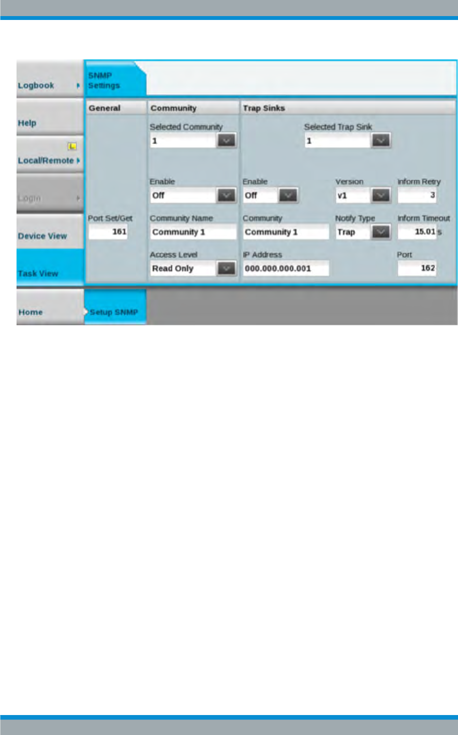
Task View Description
R&S®Tx9
230Operating Manual 2109.9110.02 ─ 07
Fig. 5-1: SNMP menu
The XX9 transmitter family supports the versions SNMPv1 and SNMPv2c. Alarms can
be sent as v1Traps, v2Traps or v2Informs. Several destinations for error messages
(trapsinks) and several communities can be set with read only authorization and read/
write authorization. SNMP is a protocol for remote control and is offered only at the
remote Ethernet interface (X2 – 1000 BaseT). The system or transmitter has to be set
to remote to execute SET commands.
5.3.1.3 Settings on Manager End
The basic SNMP settings (port, community) on the manager end and transmitter end
have must match. You typically define these settings for each IP address in your pro-
gram (e.g. MIB browser). The SNMP version is also set in the manager; the transmitter
then detects this automatically. Subsequently, SNMP communications should already
be functioning at a basic level.
System Control
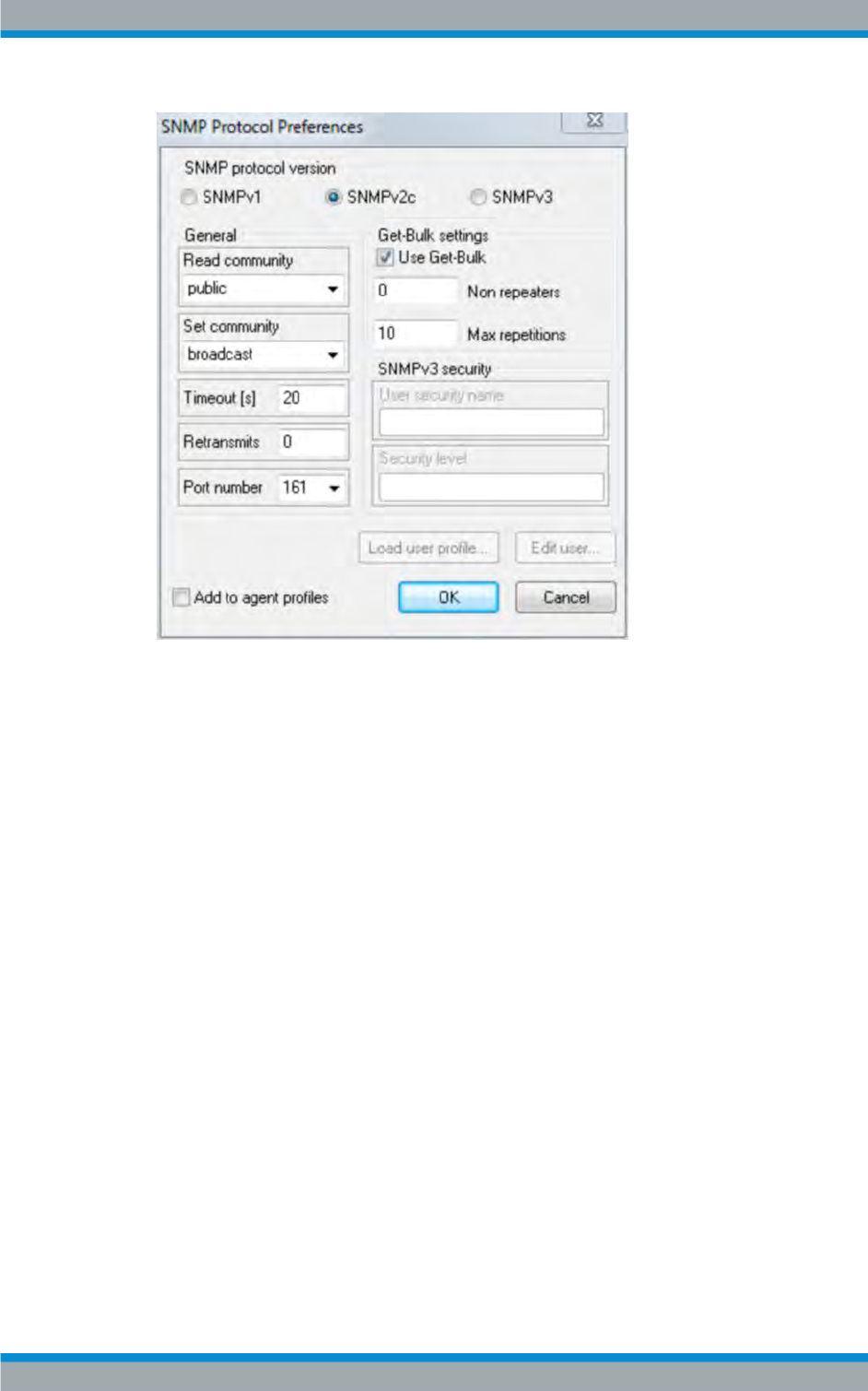
Task View Description
R&S®Tx9
231Operating Manual 2109.9110.02 ─ 07
Fig. 5-2: SNMP manager settings
Being able to monitor and control a transmitter with SNMP requires the device's MIB
on the manager end and a program that can interpret the MIB. You can load all availa-
ble MIBs from any device using a web browser.
●Log in using the WebGUI and select the menu Task View > System Control >
Downloads > Download SNMP MIBs
●Save the mibs.zip file to your computer
●Load the following MIBs in the MIB browser:
–RS-COMMON-MIB
– RS-XX9-SMI-MIB and RS-XX9-TC-MIB
– RS-XX9-COMMON-MIB
– MIB of the standby concept, standard or option
A detailed description of the MIBs, the information that they contain and the associated
options is given below.
MIBs from Rohde & Schwarz and the Munich-based Broadcast Technology Institute
(IRT) are available. MIBs from IRT allow transmitters to be linked using SNMP irre-
spective of the manufacturer. They are, however, limited with respect to their function-
ality. Some particular features to keep in mind when using IRT MIBs are listed in the
document "SoftwareMiniSpecification – SNMP for XX9".
The MIBs have the naming convention RS-XX9-<TV/radio standard>-<function/
option>-MIB. Examples include: RS-XX9-DVBT2-MIB for DVB-T2 and RS-XX9-AIR-
COOLING-MIB for air cooling.
System Control
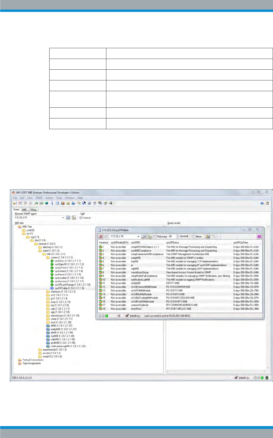
Task View Description
R&S®Tx9
232Operating Manual 2109.9110.02 ─ 07
Examples of MIBs and contents
MIB Description
RS-COMMON-MIB Contains general Rohde & Schwarz definitions
RS-XX9-SMI-MIB Contains top-level definitions of other XX9 MIBs
RS-XX9-TC-MIB Contains definitions for textual conventions used in other MIBs
RS-XX9-COMMON-MIB Contains definitions that comply with all of the transmitters from the XX9 family
(e.g. configuration)
RF-XX9-TX-MIB Contains definitions for single transmitters not dependent on the TV standard
RF-XX9-MTX-MIB Contains definitions for MultiTx and N+1 systems
5.3.1.4 Which MIBs Must Be Used?
The device can be queried by SNMP in order to find out which MIBs have been imple-
mented. This information is contained in the table "sysORTable"
(OID .iso(1).org(3).dod(6).internet(1).mgmt(2).mib-2(1).system(1).sysORTable(9) of
the SNMPv2 MIB). There is a corresponding MIB for each type of modulation.
Fig. 5-3: sysORTable display
System Control

Task View Description
R&S®Tx9
233Operating Manual 2109.9110.02 ─ 07
MIB Description
RS-COMMON-MIB This MIB contains general Rohde & Schwarz definitions.
RS-XX9-AIR-COOLING-MIB This MIB contains parameters for air-cooled transmitters.
RS-XX9-COMMON-MIB This MIB contains general data that supports every device:
●Transmitter configuration
●Option keys
●Software update
●SNMP configuration
●Releasing a test notification
This information always applies to the device using SNMP.
RS-XX9-LIQUID-COOLING-MIB This MIB contains parameters for liquid-cooled transmitters, either
with internal Rohde & Schwarz cooling or with (external) station cool-
ing.
RS-XX9-MTX-MIB This MIB contains parameters independent of the type of modulation
for:
●MultiTx
●N+1
RS-XX9-SMI-MIB This MIB contains top-level definitions of other XX9 MIBs.
RS-XX9-TC-MIB This MIB contains definitions for textual conventions used in other
MIBs.
RS-XX9-TX-MIB This MIB contains parameters independent of the type of modulation
for:
●Single drive standby concepts
●Passive dual drive
●Active dual output stage
This applies to all power classes in the medium- and high-power
range.
RS-XX9-ATSC-MIB This MIB contains parameters for ATSC signal processing.
RS-XX9-ATV-MIB This MIB contains parameters for ATV signal processing.
RS-XX9-DAB-MIB This MIB contains parameters for DAB signal processing.
RS-XX9-DTMB-MIB This MIB contains parameters for DTMB signal processing.
RS-XX9-DVBT-MIB This MIB contains parameters for DVBT signal processing.
RS-XX9-DVBT2-MIB This MIB contains parameters for DVBT2 signal processing.
RS-XX9-FM-MIB This MIB contains parameters for FM signal processing.
RS-XX9-ISDBT-MIB This MIB contains parameters for ISDBT signal processing.
5.3.1.5 Which OIDs from a MIB Must Be Used?
Different parameters are available depending on the system being queried. For exam-
ple, txExcAutoOperationMode (in RS-XX9-TX-MIB) returns the response NoSuch-
Name when you query a single transmitter, since it has no automatic exciter switch-
over. It is easy to find out which parameters are valid by checking the conformance
statements. In the example for automatic exciter switchover above, the OID txExcAu-
toOperationMode is contained in the txObjsExciterAutomatic object group.
System Control
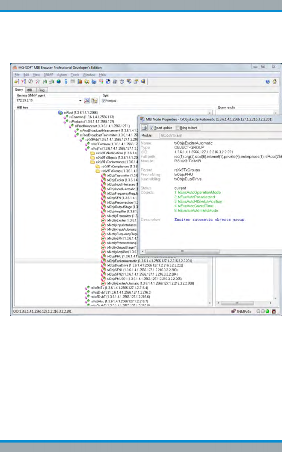
Task View Description
R&S®Tx9
234Operating Manual 2109.9110.02 ─ 07
For N+1 systems this also means that unavailable parameters may receive the
response NoSuchName, e.g. parameters from the transmitter A8 if only a 4+1 system
is present.
Fig. 5-4: Groups display
5.3.1.6 Setting Alarms
Parameters that allow configuration of the transmitter alarms can be found under the
OID "commonSnmpConfiguration". For example, it is possible to switch off the IRT
alarms (factory default setting: on) and to switch on Rohde & Schwarz alarms (factory
default setting: off). The transmitter-specific alarms offer an extensive range of configu-
ration possibilities. In addition, it is also possible to assign a user-selectable priority
and to check the current status. Since the Rohde & Schwarz MIBs contain a large
number of alarms, three predefined groups for faults, warnings and information exist, to
System Control
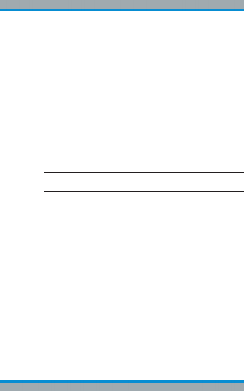
Task View Description
R&S®Tx9
235Operating Manual 2109.9110.02 ─ 07
which all alarms are assigned. For each alarm, the respective alarm class is given in
the binding AlarmClass.
A possible and recommended configuration would therefore be to disable the IRT
alarms and to enable the Rohde & Schwarz alarms of the fault class:
●irtNotificationsAllOff: OID 1.3.6.1.4.1.2566.127.1.2.216.2.1.3.3.0
●rsNotificationsAllFaultsOn; OID 1.3.6.1.4.1.2566.127.1.2.216.2.1.3.6.0
The example shows alarm class fault (1) for the alarm "txSummaryFault" (transmitter
sum fault).
Alarms are always collected in the Notifications branch in the MIBs. They always have
at least three bindings.
●Alarm Class: Predefined, fixed alarm class
●Priority: User-selectable priority
●State: Current state of the alarm
"State" is defined in NotificationState in the MIB RS-XX9-TC-MIB:
undefined(1) State is not available
off(2) Alarm is inactive or not available
fault(3) Alarm corresponds to an error
warning(4) Alarm corresponds to a warning
ok(5) Alarm does not correspond to either an error or a warning or alarm is OK
Matching the alarms, there are one or more notification tables in the MIBs on the
Objects branch. Information is displayed together there.
5.3.1.7 Testing the SNMP Communications
In the following example, a transmitter with the IP address 172.29.12.43 queries the
OID sendTestNotification (1.3.6.1.4.1.2566.127.1.2.216.2.1.3.1). The response from
the agent is "idle(1)". Using a further test, you can check whether the transmitter sends
an alarm message in the event of an error and whether this message reaches the
alarm destinations. To do so, set an OID sendTestNotification to the value of 2 (trig-
ger), which triggers a commonTest trap (1.3.6.1.4.1.2566.127.1.2.216.2.0.1000). This
alarm is sent to all receivers that have been entered for the alarms (trapsinks, see
above). This type of error message functions in a slightly different way than that used
for querying and setting values (default: UDP Port 161 for SET/GET and UDP Port 162
for alarms).
The following image shows that the testTrap has been received correctly by the
tce900-100100 device (serial number 100100).
System Control
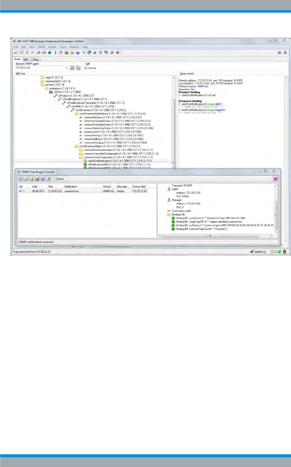
Task View Description
R&S®Tx9
236Operating Manual 2109.9110.02 ─ 07
Fig. 5-5: testTrap display
5.3.1.8 Setting Alarms Using SNMP
As an alternative to a web browser, you can also configure trapsinks with SNMP as
well. The procedure is described in RFC 3413.
System Control
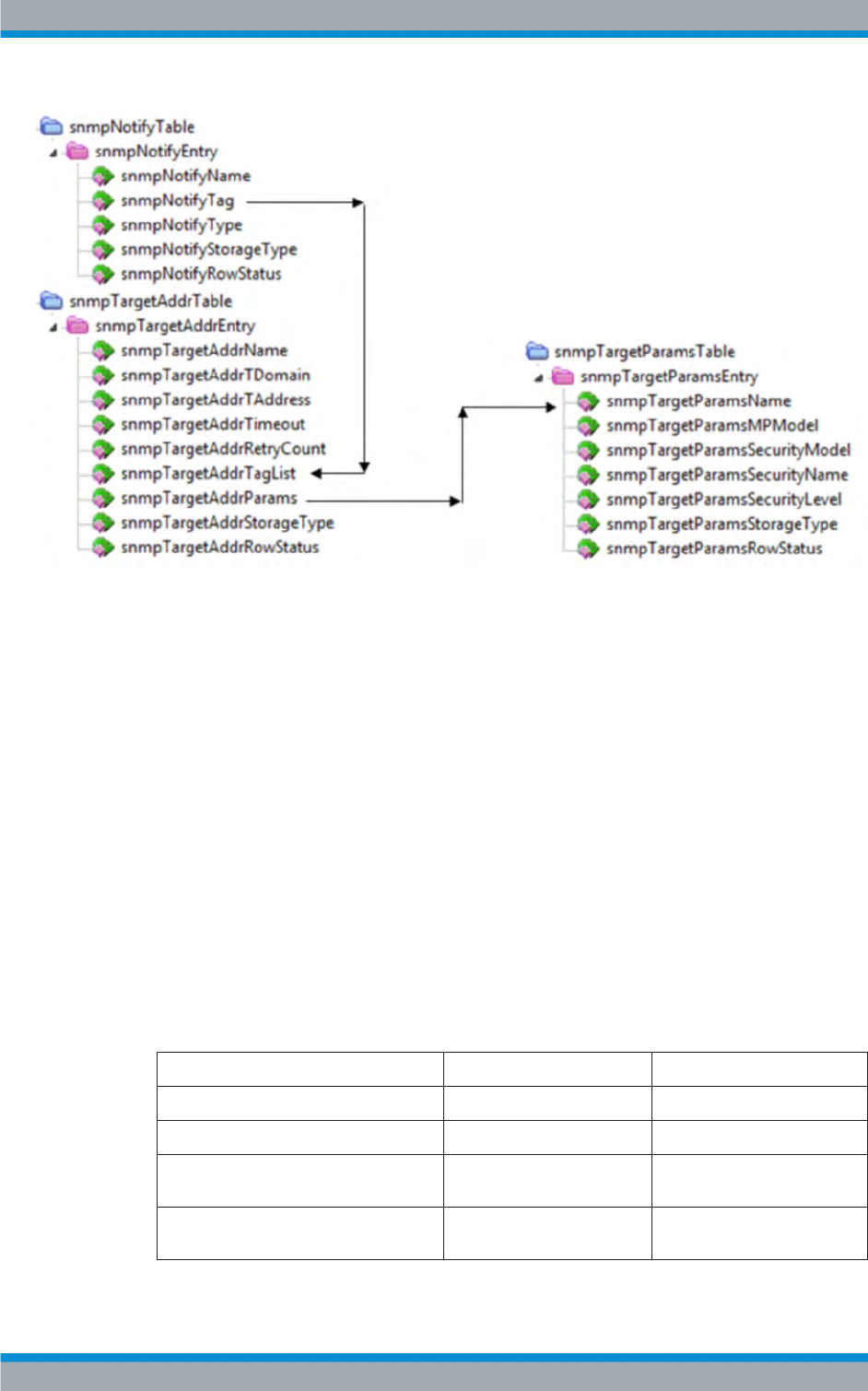
Task View Description
R&S®Tx9
237Operating Manual 2109.9110.02 ─ 07
Fig. 5-6: TargetTables display
There are three tables to be used, contained in SNMP-TARGET-MIB and SNMP-
NOTIFICATION-MIB: snmpNotifyTable, snmpTargetAddrTable and snmpTargetPar-
amsTable:
●snmpNotifyType: trap(1) or inform(2)
●snmpTargetAddrTDomain / snmpTargetAddrTAddress: Address snmpTarge-
tAddrTDomain: 1.3.6.1.6.1.1 (snmpUDPDomain), this makes snmpTargetAddrTAd-
dress six octets; the first four octets correspond to the IP address and the last two
to the UDP port
●snmpTargetAddrTimeout, snmpTargetAddrRetryCount: Additional settings for
inform
●snmpTargetParamsMPModel: 0 (SNMPv1) or 1 (SNMPv2c)
●snmpTargetParamsSecurityModel: Currently just 2 (SNMPv2c)
●nmpTargetParamsSecurityName: Example: public
●snmpTargetParamsSecurityLevel: Currently just noAuthNoPriv(1)
The SNMP agent uses the following default values:
snmpNotifyName rsdef1 rsdef2
snmpNotifyTag trap inform trap inform
snmpNotifyType trap(1) inform (2) trap(1) inform (2)
snmpNotifyStorageType nonVolatile(3)
nonVolatile(3)
nonVolatile(3) nonVolatile(3)
snmpNotifyRowStatus readOnly (5)
readOnly (5)
readOnly readOnly(5)
System Control
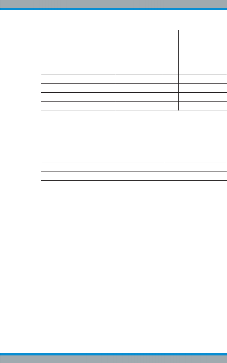
Task View Description
R&S®Tx9
238Operating Manual 2109.9110.02 ─ 07
getAddrName target1 to target5
snmpTargetAddrTDomain 3.6.1.6.1.1 1.3.6.1.6.1.1
snmpTargetAddrTAddress 0x0101010100a2 0x0101010100a2
snmpTargetAddrTimeout 1500 1500
snmpTargetAddrRetryCount 3 3
snmpTargetAddrTagList trap trap
snmpTargetAddrParams param2 param2
snmpTargetAddrStorageType permanent(4) permanent(4)
snmpTargetAddrRowStatus notInService(2) notInService(2)
snmpTargetParamsName param1 param2
snmpTargetParamsMPModel 0 1
snmpTargetParamsSecurityModel 1 2
snmpTargetParamsSecurityName public public
snmpTargetParamsSecurityLevel nNoPriv(1) noAuthNoPriv(1)
snmpTargetParamsStorageType permanent(4) permanent(4)
snmpTargetParamsRowStatus active(1) active(1)
5.3.1.9 Type plates - the ENTITY MIB
The ENTITY MIB contains information on type plates. The table commonEntPhysicalT-
able in RS-XX9-COMMON-MIB serves as an extension of this. It includes values such
as operating hour meters and the number of restarts.
The following figure shows an excerpt from the table entPhysicalTable of the ENTITY
MIB.
System Control
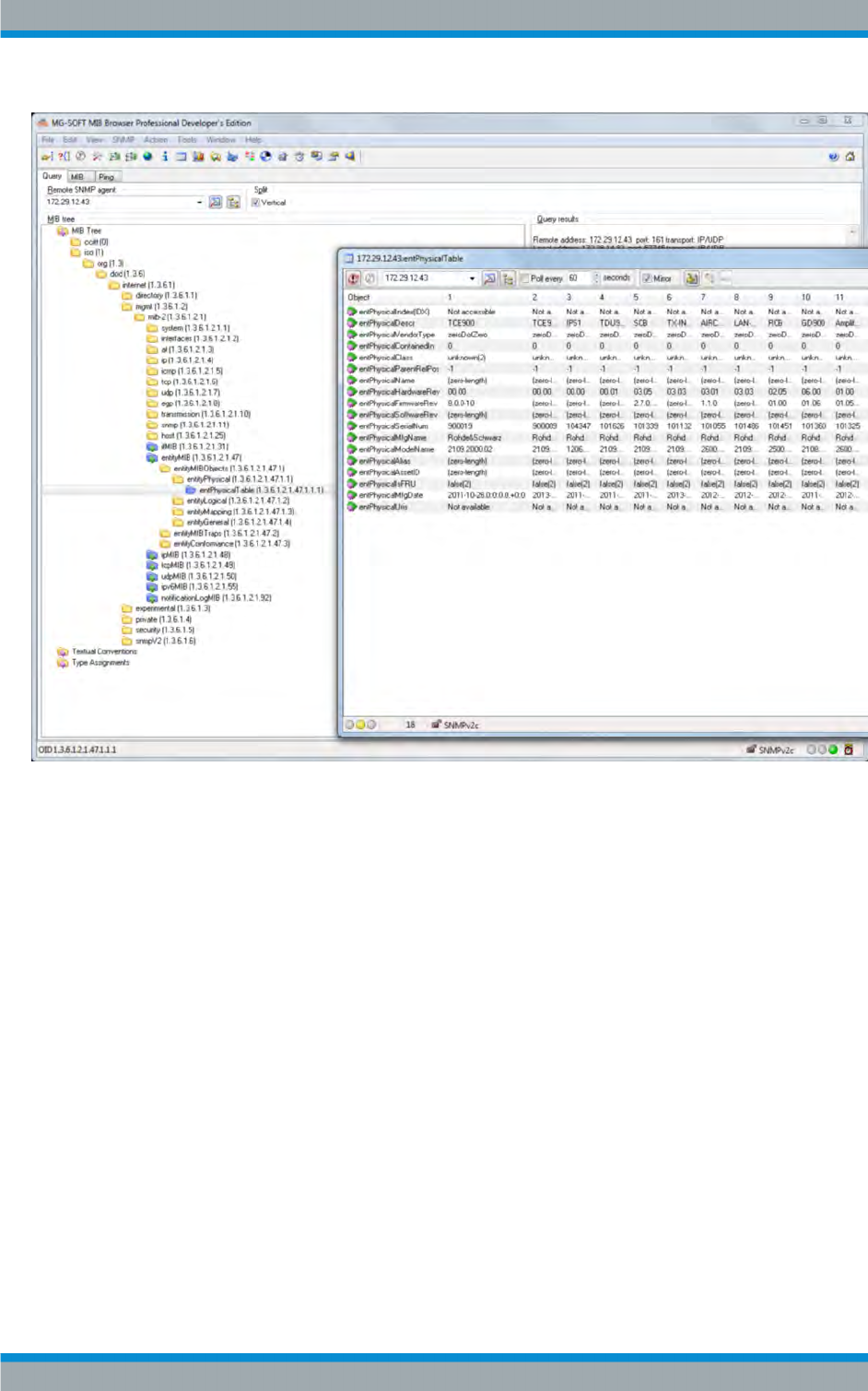
Task View Description
R&S®Tx9
239Operating Manual 2109.9110.02 ─ 07
Fig. 5-7: entPhysical display (excerpt)
The extension of the entPhysicalTable in RS-XX9-COMMON-MIB (commonEntPhysi-
calTable):
System Control
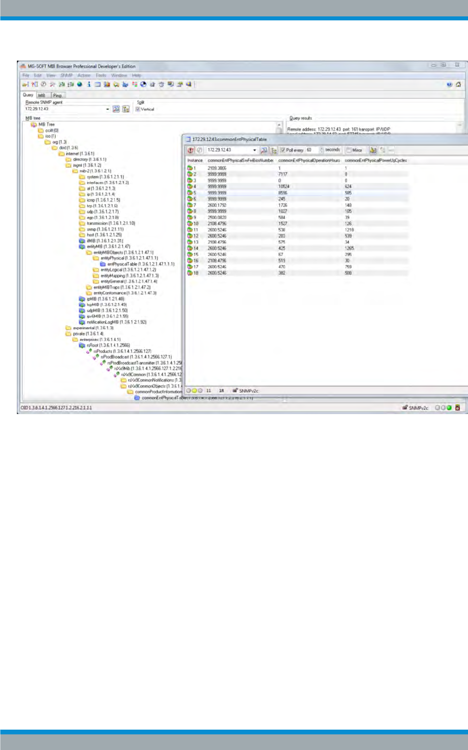
Task View Description
R&S®Tx9
240Operating Manual 2109.9110.02 ─ 07
Fig. 5-8: commonEntPhysical display
5.4 Maintain Software
5.4.1 Software Update
The software of the R&S®TCE900 can be updated. Installing a new version will make
new features available and will improve the functionality of the transmitter. New soft-
ware versions are supplied as a file which can be run under MS Windows. Apart from
the instrument software, this file also contains the "R&S Software Distributor" tool
which allows the software to be installed on several R&S®TCE900 units at the same
time. The software supports all R&S®TCE900 modules within a transmitter system.
The R&S®TCE900 must be prepared for the software update before installation is star-
ted. To ensure that a R&S®TCE900 is found in the network by the R&S Software Dis-
tributor, the software update must be started in the "Task View" > "Maintain SW" >
"SW Update" menu of the respective R&S®TCE900. Alternatively, "Update Mode" can
Maintain Software

Task View Description
R&S®Tx9
241Operating Manual 2109.9110.02 ─ 07
be set to "Permanent" in this menu. This allows the software to be updated at any time
without preparation.
The software update can then be performed on a Windows PC which is connected to
the transmitter via the network.
●Deactivate the energy-saving option of the network card in the PC:
–Under Windows, call the Device Manager by selecting Start > Control Panel >
System > Hardware > Device Manager.
– In the Device Manager, select the correct network adapter and double-click to
call the associated Properties window.
– In the Properties window, select the Power Management tab and (if neces-
sary) deactivate the Allow computer to turn off this device to save power
option.
●On the PC, start the installation software. The start window of the R&S Software
Distributor appears.
●Confirm the default setting Remote Installation with Next.
The installable software updates are displayed. To obtain additional information
about an update, mark the update with the cursor and then click the Info button.
●Search for updatable devices in the network by clicking Next. After a few seconds
a list of the found devices is displayed.
●If no devices are found even though the network settings are correct , the settings
of the R&S Software Distributor must be checked under Options and corrected if
necessary.
–Enable VISA must be deactivated using the checkbox.
–Device Group must match the device group displayed in the Software Update
menu of the TCE.
– Save the changed settings by clicking Save Options and then search again by
clicking Rescan.
●In the Device List, select the device to be updated by marking the checkbox.
●Start the update by clicking Install.
●When the update is complete, a message is displayed in the info field at the bottom
left of the window. The TCE900 is rebooted automatically.
If the update stops prematurely (i.e. the message "Copying/Installing ... %" stops
before the 100 % mark is reached), abort the update by clicking Cancel and then
restart the R&S Software Distributor.
"SW Update" parameters
●Path: Task View (Home) > Maintain SW > SW Update
Maintain Software

Task View Description
R&S®Tx9
242Operating Manual 2109.9110.02 ─ 07
Name Description Value range Access right
Update Status
(Software Update)
Indicates whether the R&S®TCE900 is ready for the device software
update.
●Stopped:
The R&S®TCE900 cannot be found in the network by the Soft-
ware Distributor. It is not possible to update the software.
●Started:
The R&S®TCE900 is listed in the update list of the R&S Software Dis-
tributor and the software can be updated.
Stopped, Started Read only
Update Mode
(Software Update)
Indicates how the software of the TCE can be updated.
●Manual:
The R&S®TCE900 can be found by the Software Distributor for
approx. 90 seconds after the "Start Update" button is pressed.
●Permanent:
The R&S®TCE900 can be found by the Software Distributor at any
time. The software can be updated at any time without the
R&S®TCE900 needing to be prepared for a software update.
The setting can be changed here.
Manual, Perma-
nent
Maintenance
SW Version (Soft-
ware Update)
Shows the software version currently installed on the TCE. The first
number of the displayed SW version must be identical on all
R&S®TCE900 units of a system to ensure that the system operates
correctly.
- Read only
Device Name
(Software Update)
Shows the device name under which this R&S®TCE900 appears in
the list of the Software Distributor.
The setting can be changed here.
Up to 20 charac-
ters
Maintenance
Start Update
(Software Update)
Starts the enable phase of a software update if "Update Mode" is set
to "Manual".
The enable phase is active for approx. 90 seconds. During this time,
the R&S®TCE900 can be found in the network by the Software Dis-
tributor.
- Maintenance
Device Group
(Software Update)
Shows the device group. The displayed device group must be the
same as the device group set in the Software Distributor so that this
R&S®TCE900 is displayed in the list of devices found by the Software
Distributor.
DEFAULT Read only
Reboot (Software
Maintenance)
Reboots the R&S®TCE900. - Maintenance
5.4.2 Backup/Restore
This function is used to make a complete backup of the currently installed software ver-
sion as well as all settings of the R&S®TCE900. This backup is created in the file sys-
tem of the R&S®TCE900 and can then either be downloaded to an external storage
medium or restored at a later time.
Backups of the same R&S®TCE900 and also of other R&S®TCE900 units can be
uploaded from an external storage medium and then restored.
If a backup is made before the software of the R&S®TCE900 is updated, it is then pos-
sible to revert to the old software version after the software has been updated by
restoring the old version from the backup.
Maintain Software

Task View Description
R&S®Tx9
243Operating Manual 2109.9110.02 ─ 07
In order to download a backup to an external storage medium or to upload a backup
from an external storage medium, there must be a direct network connection between
the R&S®TCE900 and a PC. This function is not available for R&S®TCE900 units
which can be reached only indirectly via a TCE900 SysCtrl.
"Backup/Restore" parameters
●Path:Task View (Home) > Maintain SW > Backup/Restore
Name Description Value range Access right
Backup State
(Backup/Restore)
Indicates the action which has just been performed.
●Ready
The backup/restore functions can be started.
●Backup in Progress
A backup has been started and will then be stored in the internal
file system of the R&S®TCE900.
●Check in Progress
The backup uploaded to the R&S®TCE900 is being checked.
●Restore in Progress
The backup stored in the internal file system is being restored on
the R&S®TCE900.
●Download in Progress
The backup stored in the R&S®TCE900 is being copied to an
external storage medium.
●Upload in Progress
A backup is being copied from an external storage medium to the
TCE900.
Ready, Backup/
Check/Restore/
Download/
Upload in Pro-
gress
Read only
Start Backup
(Backup/Restore)
Starts the creation of a backup. The backup is stored in the internal file
system of the R&S®TCE900 and contains the current program version
as well as all setting values of the R&S®TCE900. The creation of a
backup causes the R&S®TCE900 to reboot.
- Maintenance
Start Restore
(Backup/Restore)
Restores the program version as well as all settings of the
R&S®TCE900 from the backup which was stored in the file system of
the R&S®TCE900.Restoring a backup causes the TCE to reboot.
-Maintenance
Download File
(Backup/Restore)
Copies the backup stored in the file system of the R&S®TCE900 to an
external storage medium. This function is only available if the
R&S®TCE900 is operated via a web browser.
- Maintenance
Upload File
(Backup/Restore)
Copies a backup from an external storage medium to the
R&S®TCE900. This function is only available in the case of operation
via a web browser.
- Maintenance
Maintain Software

Task View Description
R&S®Tx9
244Operating Manual 2109.9110.02 ─ 07
Name Description Value range Access right
File State (File
Info)
Indicates the status of the backup stored on the R&S®TCE900.
●Available Backup OK
The backup is OK.
●No Backup Available
No backup has yet been made on or uploaded to the
R&S®TCE900.
●Invalid Backup
The backup is faulty. The backup cannot be used.
●Invalid Device
The backup was not made on a R&S®TCE900. It is not compati-
ble with this device. None of the files from this backup can be
restored on this R&S®TCE900.
●Invalid Checksum
The check routine performed on the backup returned a checksum
error. The backup cannot be used in this case.
●Not Compatible
The backup loaded from an external storage medium is not com-
patible with the R&S®TCE900. The backup cannot be used in
this case.
●Invalid Software Version
To be able to operate, the R&S®TCE900 requires a more recent
software version than that contained in the backup.
- Read only
Tx Name (File
Info)
Shows the name of the transmitter from which the backup originates. - Read only
Name (File Info) Shows the name of the device from which the backup originates. If the
device name is not TCE900, the backup cannot be restored. The Inva-
lid Device fault is displayed in this case.
- Read only
Part Number (File
Info)
Shows the part number of the R&S®TCE900 from which the backup
originates. The backup can only be restored if the displayed part num-
ber is identical to the part number of the R&S®TCE900. The Not
Compatible fault will otherwise be displayed.
- Read only
Date Time (File
Info)
Indicates when the backup was made. - Read only
Serial Number
(File Info)
Shows the serial number of the instrument from which the backup was
made.
- Read only
SW Version (File
Info)
Shows the software version which the backup contains. - Read only
5.5 Options
Under "Options" it is possible to activate additional features on a transmitter. The fea-
tures requested when a transmitter was ordered are activated at the factory before the
transmitter is delivered. Additional features can be purchased at any time from your
local Rohde & Schwarz sales partner.
Options are stored on a SIM card inside the R&S®TCE900 and are always valid for the
R&S®TCE900 in which the SIM card is installed. Options can be transferred to another
R&S®TCE900 by swapping the SIM card.
The Task View (Home) > Options > Status menu provides an overview of the available
or installed options.
Options

Task View Description
R&S®Tx9
245Operating Manual 2109.9110.02 ─ 07
In addition to permanent options, there are also temporary options. These options
deactivate automatically after a certain period of time. The period of validity of tempo-
rary options is shown in the Task View (Home) > Options > Details menu.
Features are enabled by installing a valid activation key in the Task View (Home) >
Options > Manage Keys menu.
"Manage Keys" parameters
●Path:Task View (Home) > Options > Manage Keys
Name Description Value range Access right
Option Key
(Install/Deinstall)
Used to enter an activation key. 30 characters Maintenance
Message (Install/
Deinstall)
●Please enter a key
Prompt to enter a key.
●Key OK
The key has been entered successfully (the display changes back
to "Please enter a key" after a few moments).
●Invalid format
The entered key was invalid.
Please enter a
key, Key OK,
Invalid format
Read only
Options

Task View Description
R&S®Tx9
246Operating Manual 2109.9110.02 ─ 07
Options

Operating the Device Manager
R&S®Tx9
247Operating Manual 2109.9110.02 ─ 07
6 Operating the Device Manager
Using the Device Manager, the device type plates of all TCE900 units and the type
plates of the modules they contain can be polled.
The type plates contain information about the current software version of programma-
ble modules and all necessary information for spare parts procurement.
The Device Manager is started using the "Device Manager" button on the system,
transmitter or exciter level.
6.1 Basic Settings
The structure of the transmitter system is configured in the "Basic Setup" menu. Each
R&S TCE900 is assigned its logical function together with the other R&S TCE900
units, the physical installation position of the individual R&S TCE900 units is set and
the distribution of transmitters and R&S TCE900 units in the racks is described.
The basic settings are made for each R&S TCE900 in the system and must be entered
in the specified sequence:
●Hardware equipment ("Boards" menu tab)
The hardware modules which each R&S TCE900 contains and at which position
these modules are inserted in the R&S TCE900 base unit must be configured for
each R&S TCE900.
●Definition of the logical function
The task that each R&S TCE900 is to fulfill in the system must be defined.
●Integration of the R&S TCE900 in the transmitter system
Depending on their function, some R&S TCE900 units require additional informa-
tion regarding:
–system variant (MultiTX, N+1)
– transmitter variant (Redundancy, Modulation, Amplifier Type)
– assignment to a transmitter (TX Number, Exciter A/B)
●Physical structure of the transmitter system
Depending on their function, some R&S TCE900 units require additional informa-
tion regarding:
– total number of transmitter racks
– number of racks per transmitter
●Physical installation location of the R&S TCE900 units
Each R&S TCE900 must be assigned the following:
– number of the rack in which the R&S TCE900 is installed
– number of the installation slot within a rack
●Assignment of transmitters to racks ("Racks" menu tab)
Each R&S TCE900 with the "Rack Control" function must be assigned those trans-
mitters which are installed in the racks that the "Rack Control" function monitors.
Basic Settings
Operating the Device Manager
R&S®Tx9
248Operating Manual 2109.9110.02 ─ 07
Changes to the basic settings only become effective when the R&S TCE900 has been
restarted.
In the tables below, "?" means that it must be taken into consideration whether an air
cooling interface (ACIF) or a TX interface is installed. See the detailed description of
the "Cooling Control" and "Rack Control" parameters in the table "Description of set-
ting values".
Assignment of logical functions
Table 6-1: "Functions" for SingleTX systems (for TMU9 and TMV9 only)
Transmitter type System
Control
TX Control Exciter Cooling
Control
Rack Con-
trol
Single drive
Exciter X X X ? ?
Backup drive
Exciter A X X X ? ?
Exciter B - X X - -
Dual drive
System Control X - - ? ?
Exciter A - X X - -
Exciter B - X X - -
Table 6-2: "Functions" for MultiTX systems (<n> = 1 to 8)
Transmitter type System
Control
TX Control Exciter Cooling Con-
trol
Rack Con-
trol
Single drive
System Control X - - ? X
Exciter (TX <n>) - X X - -
Dual drive
System Control X - - ? X
Exciter A (TX <n>) - X X - -
Exciter B (TX <n>) - X X - -
Table 6-3: "Functions" for N+1 systems (<n> = 1 to 8; TXB: <n> = 9)
Transmitter type System
Control
TX Control Exciter Cooling
Control
Rack Con-
trol
Single drive
System Control X - - ? X
Exciter (TX A<n>, TX B) - X X - -
Basic Settings
Operating the Device Manager
R&S®Tx9
249Operating Manual 2109.9110.02 ─ 07
Transmitter type System
Control
TX Control Exciter Cooling
Control
Rack Con-
trol
Rack Control (where
applicable)
- - - - X
Dual drive
System Control X - - ? X
Exciter A (TX A<n>, TX
B)
- X X - -
Exciter B (TX A<n>, TX
B)
- X X - -
Rack Control (where
applicable)
- - - - X
Table 6-4: "Setup" for SingleTX systems (for TMU9 and TMV9 only)
Transmitter type System Variant TX
Number
Exciter Redundancy No. of
Transmit-
ters
Single drive
Exciter SingleTX/MultiTX A1 A Single drive 1
Backup drive
Exciter A SingleTX/MultiTX A1 A Backup drive 1
Exciter B - A1 B Backup drive 1
Dual drive
System Control SingleTX/MultiTX - - - 1
Exciter A - A1 A Dual drive -
Exciter B - A1 B Dual drive -
Table 6-5: "Setup" for MultiTX systems (<n> = 1 to 8)
Transmitter type System Variant TX
Number
Exciter Redundancy No. of
Transmit-
ters
Single drive
System Control SingleTX/MultiTX - - - <n>
Exciter (TX <n>) - A<n> A Single drive -
Dual drive
System Control SingleTX/MultiTX - - - <n>
Exciter A (TX <n>) - A<n> A Dual drive -
Exciter B (TX <n>) - A<n> B Dual drive -
Basic Settings
Operating the Device Manager
R&S®Tx9
250Operating Manual 2109.9110.02 ─ 07
Table 6-6: "Setup" for N+1 systems (<n> = 1 to 8; TXB <n> = 9)
Transmitter type System Variant TX
Number
Exciter Redundancy No. of
Transmit-
ters
Single drive
System Control N+1 TX - - <n>
Exciter (TX A<n>, TX B) - A<n> A Single drive -
Rack Control (where appli-
cable)
- - - -
Dual drive
System Control N+1 TX - - - <n>
Exciter A (TX A<n>, TX B) - A<n> A Dual drive -
Exciter B (TX A<n>, TX B) - A<n> B Dual drive -
Rack Control (where appli-
cable)
- - - - -
Table 6-7: IP addresses for SingleTX systems (for TMU9 and TMV9 only)
Transmitter type Ethernet Local
Single drive
Exciter 192.168.58.100
Backup drive
Exciter A 192.168.58.11
Exciter B 192.168.58.12
Dual drive
System Control 192.168.58.100
Exciter A 192.168.58.11
Exciter B 192.168.58.12
Table 6-8: IP addresses for MultiTX systems (<n> = 1 to 8)
Transmitter type Ethernet Local
Single drive
System Control 192.168.58.100
Exciter (TX <n>) 192.168.58.<n>1
Dual drive
System Control 192.168.58.100
Exciter A (TX <n>) 192.168.58.<n>1
Exciter B (TX <n>) 192.168.58.<n>2
Basic Settings

Operating the Device Manager
R&S®Tx9
251Operating Manual 2109.9110.02 ─ 07
Table 6-9: IP addresses for N+1 systems (<n> = 1 to 8; TXB <n> = 9; <m> = 2 to 9, No. of Rack Con-
trols)
Transmitter type Ethernet Local
Single drive
System Control 192.168.58.100
Exciter (TX A<n>, TX B) 192.168.58.<n>1
Rack Control (where applicable) 192.168.58.10<m>
Dual drive
System Control 192.168.58.100
Exciter A (TX A<n>, TX B) 192.168.58.<n>1
Exciter B (TX A<n>, TX B) 192.168.58.<n>2
Rack Control (where applicable) 192.168.58.10<m>
Table 6-10: Description of setting values
Name Description Value range Access right
System Con-
trol
Set this check mark if this cassette of the R&S TCE900 is
to function as a system control unit. In this case, all
remote control interfaces and (if present) a R&S TDU900
display unit must be connected to this R&S TCE900. This
R&S TCE900 can also perform the function of the N+1
automatic system. In addition to functioning as a system
control unit, other functions can also be assigned to the
same R&S TCE900 depending on the modules it con-
tains.
Disabled,
Enabled
Configuration
TX Control Set this check mark if this cassette of the R&S TCE900
cassette is to function as a transmitter control unit. The
transmitter control unit contains, for example, the function
for monitoring the output power and an automatic exciter
switchover function (optional). In addition to functioning
as a transmitter control unit, other functions can also be
assigned to the same R&S TCE900 depending on the
modules it contains. This function must always be activa-
ted together with the "Exciter" function on the same
R&S TCE900.
Disabled,
Enabled
Configuration
Exciter Set this check mark if this R&S TCE900 cassette contains
at least one coder board and one RF board. With a
R&S TCE900 which is configured as an exciter, the "TX
Control" function must be activated at the same time,
unless the R&S TCE900 exciter is to be operated as a
standalone instrument. In addition to functioning as an
exciter, other functions can also be assigned to the same
R&S TCE900 depending on the modules it contains.
Disabled,
Enabled
Configuration
Cooling Con-
trol
Set this check mark if this R&S TCE900 cassette contains
at least one cooling interface or one air cooling interface.
In addition to functioning as a cooling control unit, other
functions can also be assigned to the same R&S TCE900
depending on the modules it contains. The "Cooling Con-
trol" function must always be activated together with the
"Rack Control" function on the same R&S TCE900.
Disabled,
Enabled
Configuration
Basic Settings

Operating the Device Manager
R&S®Tx9
252Operating Manual 2109.9110.02 ─ 07
Name Description Value range Access right
Rack Control Set this check mark if this R&S TCE900 is to monitor rack
components (e.g. overvoltage protection) or door con-
tacts. A "TX Interface" module must be installed in the
R&S TCE900. With most system configurations, the Rack
Control function is together with the System Control func-
tion on the same R&S TCE900. The only exception are
multirack N+1 systems in which more than one Rack
Control are installed. With THx9, the "Rack Control" func-
tion must always be activated together with the "Cooling
Control" function on the same R&S TCE900.
With TMx9, the Rack Control function must be activated if
an air cooling interface is installed in the R&S TCE900
and the "Cooling" function is activated.
Disabled,
Enabled
Configuration
System Var-
iant
Indicates whether the system is a SingleTX, MultiTX or N
+1 system.
The setting can be changed here if the "System Control"
function is active.
Single/
MultiTX, n+1
Configuration
TX Number Indicates the transmitter to which this R&S TCE900 is
assigned.
The setting can be changed here if the "TX Control" func-
tion is active.
TX A1 to TX
A8 + TXB
Configuration
Exciter Indicates whether this R&S TCE900 is to operate as
exciter A or exciter B. The displayed value must corre-
spond to the cabling of the two exciters at the exciter
switch. Exciter A is shown in the case of single drive
transmitters.
The setting can be changed here if the "Exciter" function
is active.
Exc A, Exc B Configuration
ParIO Indicates whether remote control has been activated by
means of parallel contacts. ParIO 32/80 corresponds to a
parallel remote control interface card with 32 inputs and
80 outputs. ParIO 9/12 corresponds to a parallel remote
control interface card with 9 inputs and 12 outputs.
Remote control can be connected to a R&S TCE900 with
the System Control function. In the case of N+1 systems,
it is also possible to connect remote control to a
R&S TCE900 with the TX Control function, but certain
restrictions will then apply.
The setting can be changed here if the "System Control"
or "TX Control" function is active.
Off, 32/80,
9/12
Configuration
Redundancy Indicates which redundancy method is supported by this
transmitter.
●Single Drive:
The transmitter contains one exciter.
●Dual Drive:
The transmitter contains two exciters. If the active
exciter fails, an automatic switchover function
switches the system over to the standby exciter.
●Only available with some system variants:
Backup Drive:
The transmitter contains two exciters. If the active
exciter fails, an automatic switchover function
switches the system over to the standby exciter.
The setting can be changed here if the "TX Control" func-
tion is active.
Single Drive,
Dual Drive,
Backup Drive
Configuration
Basic Settings

Operating the Device Manager
R&S®Tx9
253Operating Manual 2109.9110.02 ─ 07
Name Description Value range Access right
Transmitters Indicates how many transmitters the system contains.
The B transmitter of an N+1 system is not included here.
The setting can be changed here if the "System Control"
function is active.
1 to 8 Configuration
Modulation Indicates the modulation mode of the exciter. An appro-
priate software option must additionally be installed for
the displayed modulation mode.
Either the modulation modes for TV/DAB or those for FM/
FMHD are available.
The setting can be changed here if the "TX Control" or
"Exciter" function is active.
DVB‑T2,
DVB‑T,
ISDB‑T,
ATSC, ATV,
DAB, FM,
FMHD
Configuration
Rack Number Indicates the rack in which the R&S TCE900 module is
installed. The left-hand rack is assigned the number 1.
The setting can be changed here if the "System Control",
"TX Control" or "Exciter" function is active.
1 to 18 Configuration
Amplifier
Mode
Indicates whether the amplifiers are to be operated in
broadband or Doherty mode. To operate the amplifiers in
Doherty mode, the frequency ranges of the amplifiers
must be set to the transmit frequency. This display only
applies to amplifier types which support Doherty mode.
The setting can be changed here if the "TX Control" or
"Exciter" function is active.
Broadband,
Doherty
Configuration
Amplifiers Indicates the total number of amplifiers per output stage
of this transmitter. Whether the amplifiers are housed in
one or more racks is irrelevant. Up to 24 amplifiers per
output stage are supported (FM: up to 8 amplifiers).
The setting can be changed here if the "TX Control" func-
tion is active.
1 to 24 Configuration
Amplifier
Type
Indicates the amplifier type used in the transmitter.
●PHU901:
High‑power amplifier, UHF, liquid‑cooled.
●PMU901:
Medium‑power amplifier, UHF, air‑cooled with Doh-
erty mode.
●PHU902:
High‑power amplifier, UHF, liquid‑cooled with Doh-
erty mode.
●PHV902:
High‑power amplifier, VHF, liquid‑cooled with Doh-
erty mode.
●PMV901:
Medium‑power amplifier, VHF, air‑cooled with Doh-
erty mode.
The setting can be changed here if the "TX Control" or
"Exciter" function is active.
PHU901,
PMU901,
PHU902,
PHV902,
PMV901,
PHR901,
PMR901
Configuration
Slot Number Indicates the position at which the R&S TCE900 is instal-
led in the respective rack. In the THU9, position 1 is the
left-hand slot; in the TMU9, position 1 is the top slot.
The setting can be changed here if the "System Control",
"TX Control" or "Exciter" function is active.
1 to 12 Configuration
Basic Settings

Operating the Device Manager
R&S®Tx9
254Operating Manual 2109.9110.02 ─ 07
Name Description Value range Access right
Racks/Rack
Control
Indicates how many racks are monitored by this
R&S TCE900. Transmitters with more than 12 amplifiers
monitor 2 racks with one rack control. With all other trans-
mitters, this value must be set to 1.
The setting can be changed here if the "Rack Control"
function is active.
1 or 2 Configuration
Cooling Type Indicates the type of cooling system.
The displayed value must be suitable for the amplifier
type. Further settings are made in the "Home" > "Cooling"
> "Task View" > "Setup Cooling" menu.
Liquid, Air Configuration
Racks/
System
Indicates the total number of racks contained in the sys-
tem.
The setting can be changed here if the "System Control"
function is active.
1 to 18 Configuration
Racks/TX Indicates the number of racks that the transmitter consists
of. This setting is only relevant for THU9 transmitters with
more than 12 amplifiers. In all other cases, the value 1
must be set here.
The setting can be changed here if the "TX Control" func-
tion is active.
1 to 4 Configuration
Number of
Rack Controls
Indicates the total number of rack controls which are
active in the system.
The setting can be changed here if the "Rack Control"
function is active.
1 to 9 Configuration
Int. RF Sen-
sor
Indicates whether the internal RF test point of the ampli-
fier is to be used for measuring the transmit power.
The setting is only relevant for "Amplifier Type =
PMU901". The value "On" should be set if the transmitter
consists of exactly one amplifier and no CAN bus test
point is installed in the transmitter.
The setting can be changed here if the "Rack Control"
function is active.
Off, On Configuration
Configuration Indicates whether the selected combination of settings is
valid and nonconflicting.
The setting can be changed here.
OK, not Valid Read only
Reboot Reboots this R&S TCE900. Changes to settings in this
and the other menu tabs of the Basic Config menu only
become effective after a reboot.
Configuration
IP Address
(Local IP Set-
tings)
Used to set the IP address of the R&S TCE900 for inter-
nal communications with other R&S TCE900 units in this
system. When the system is supplied, the internal IP
addresses begin with 192.168.58. The last group of digits
differs according to the following rule:
●System Control: 100
●TX Control + Exciter: 11/12 (= TXA1, Exciter A/B) to
81/82 (= TXA8, Exciter A/B); 91/92 (= TXB, Exciter
A/B)
●Rack Control (second rack): 101
The setting can be changed here.
Configuration
Basic Settings

Operating the Device Manager
R&S®Tx9
255Operating Manual 2109.9110.02 ─ 07
Name Description Value range Access right
IP Address
(Remote IP
Settings)
Used to set the IP address of the R&S TCE900 system
control. The settings depend on the network infrastruc-
ture.
Slot Config Used to determine which module is contained in each
installation slot of the R&S TCE900 unit. Basically, any
module can be inserted into any installation slot. The rack
cabling has, however, been optimized for installation of
the modules in the following slots:
●Slot A (bottom left): RF board or TX interface
●Slot B (top center): Cooling interface (CIF or ACIF)
or ATV interface
●Slot C (bottom center): Reserved for receiver module
●Slot CD (top right): Coder board or LAN switch
The setting can be changed here.
Coder Board,
RFBoard,
TXIf, Coolin-
gIf, LAN-
SwitchIf,
ATVIf, CIF,
ACIF
Configuration
Basic Settings

Operating the Device Manager
R&S®Tx9
256Operating Manual 2109.9110.02 ─ 07
Basic Settings

User Administration
R&S®Tx9
257Operating Manual 2109.9110.02 ─ 07
7 User Administration
The user administration facility is available in conjunction with browser-based opera-
tion. The settings that you enter in user administration are also valid for opening menus
in local operation. You can use the user administration facility to perform the following
tasks.
●Create new user profiles
●Change user profiles (users and access rights)
●Delete user profiles
●Close active sessions
The "Superuser" ID with the factory‑set password 1234 gives you extensive user
administration rights.
7.1 Creating New User Profiles
Proceed as follows to create a new user profile:
1. Log on as Superuser via the web interface.
User name: Superuser
Password: 1234
The processing options and a list of existing users are displayed.
2. Select the Add new user option.
3. Enter a user name and password and the desired permissions for this user.
The password must be at least 6 characters long.
4. Click "Add user" if the settings are correct.
Click "Reset" if the settings are not correct, and enter the settings again.
7.2 Changing User Profiles (Users and Access Rights)
Proceed as follows to modify an existing user profile:
1. Log on as Superuser via the web interface.
User name: Superuser
Password: 1234
The processing options and a list of existing users are displayed.
2. From the list of existing users, select the user to be modified from the Select col-
umn.
3. Select the Change selected user option.
4. Change the user's profile according to your requirements.
Creating New User Profiles

User Administration
R&S®Tx9
258Operating Manual 2109.9110.02 ─ 07
5. Click "Change user" if the settings are correct.
Click "Reset" if the settings are not correct, and enter the settings again.
For the default users, you can change the passwords only; you cannot change access
rights.
7.3 Deleting User Profiles
Proceed as follows to delete a user profile:
1. Log on as Superuser via the web interface.
User name: Superuser
Password: 1234
The processing options and a list of existing users are displayed.
2. From the list of existing users, select the user to be deleted from the Select col-
umn.
3. Select the Delete selected user option.
4. The profile is removed from the user list.
7.4 Closing Active Sessions
To obtain information about existing sessions and end active sessions, follow this pro-
cedure.
1. Log on as Superuser via the web interface.
User name: Superuser
Password: 1234
The processing options and a list of existing users are displayed.
2. Select the Show session list option.
A list with information about the active sessions is displayed.
3. From the list of existing sessions, select the session to be closed from the Select
column.
4. Select the Delete selected session option.
The selected session is closed.
5. Select the Option Show user list option.
The list of existing users is displayed again.
Deleting User Profiles