Roseman Engineering FG3E Car Data Logger User Manual
Roseman Engineering Ltd. Car Data Logger Users Manual
UserManual.wiki
>
Roseman Engineering
>
FG3E User Manual
>
Users Manual
Contents
1.
Users Manual
2.
User Manuel
Users Manual
Navigation menu
Upload a User Manual
Namespaces
Wiki Guide
HTML
PDF
Info
Views
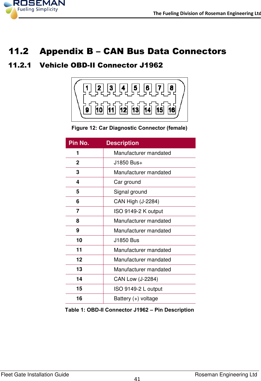
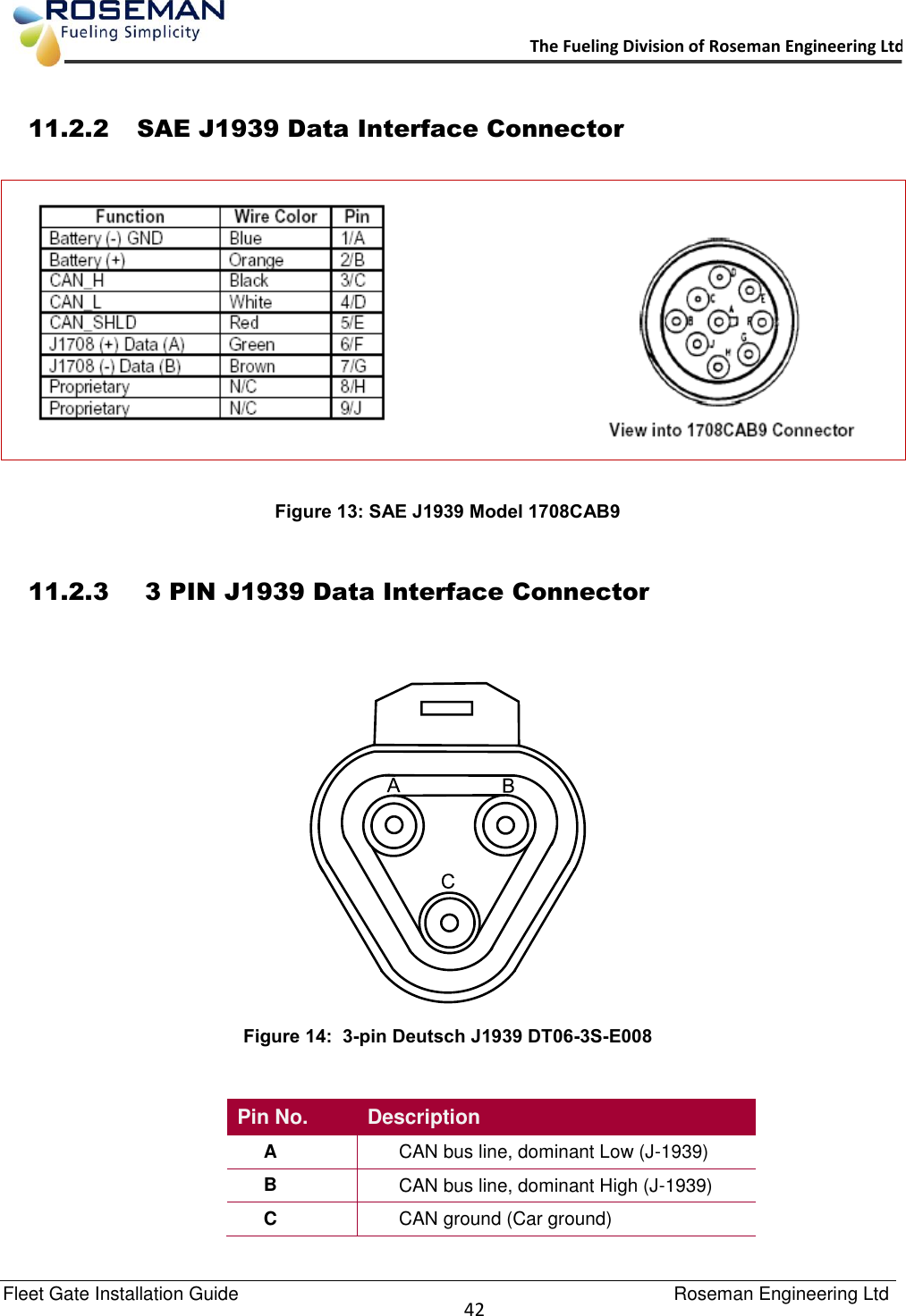
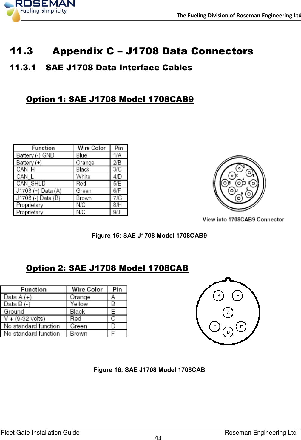
User Manual
Discussion / Help
Navigation
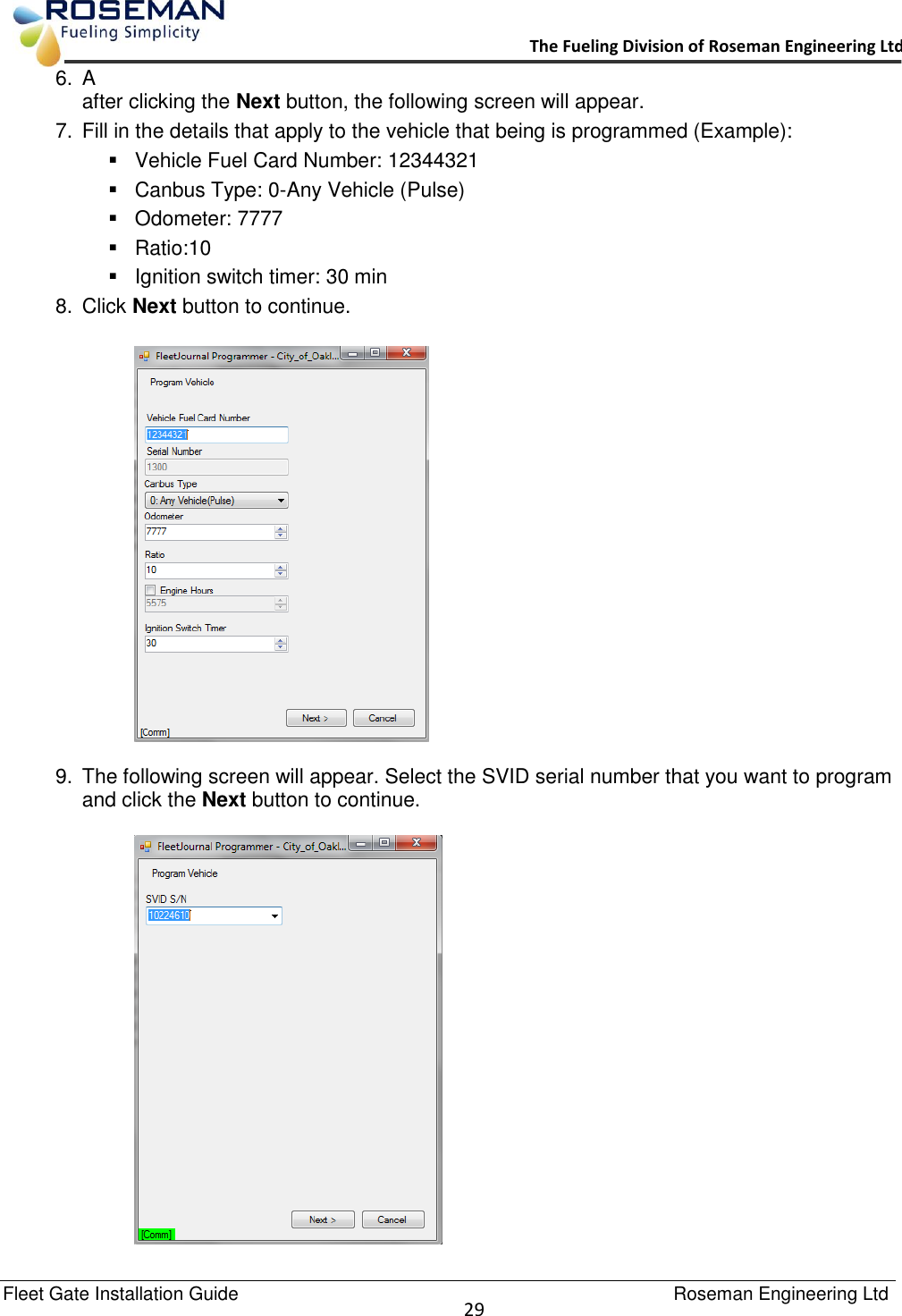
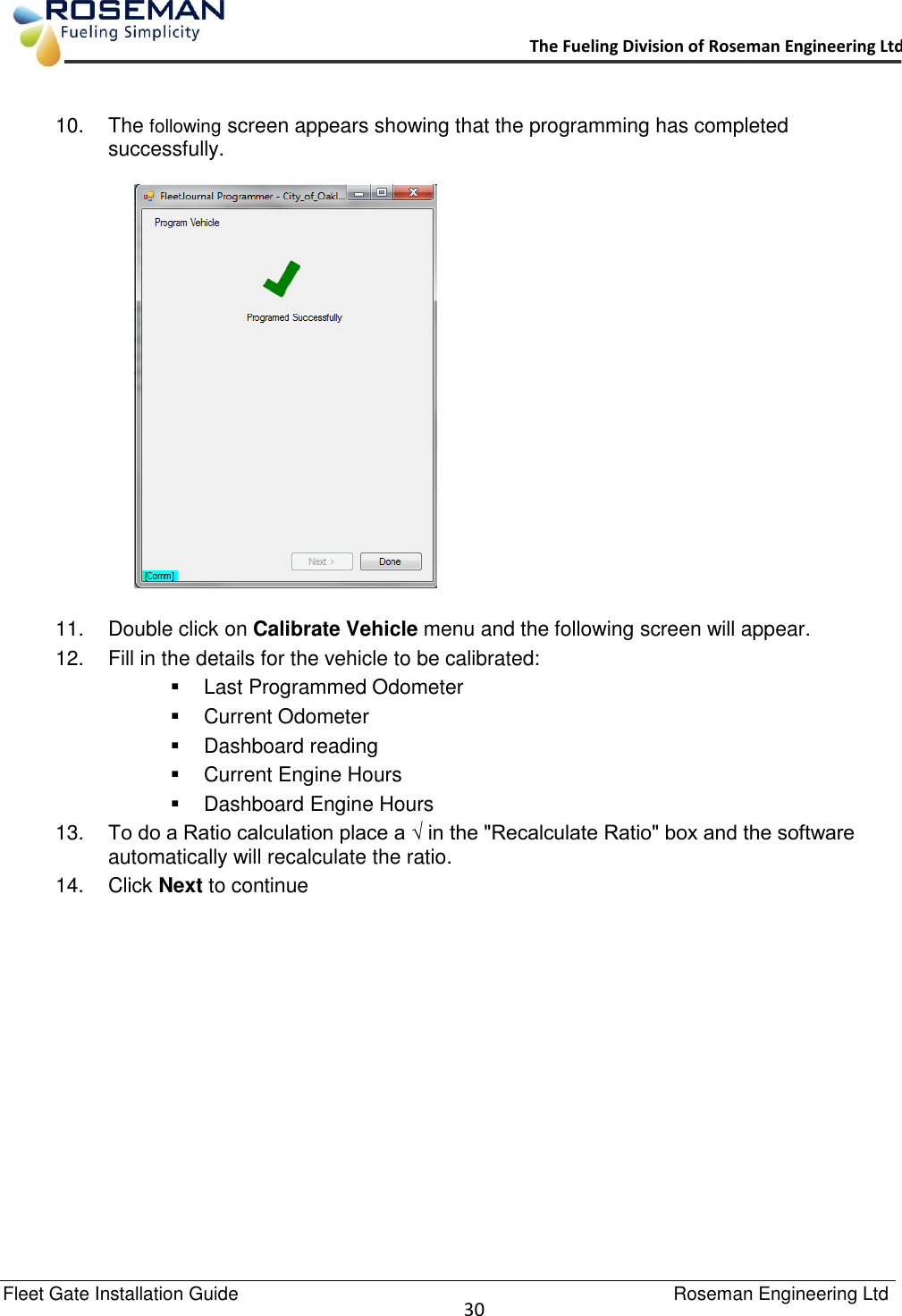
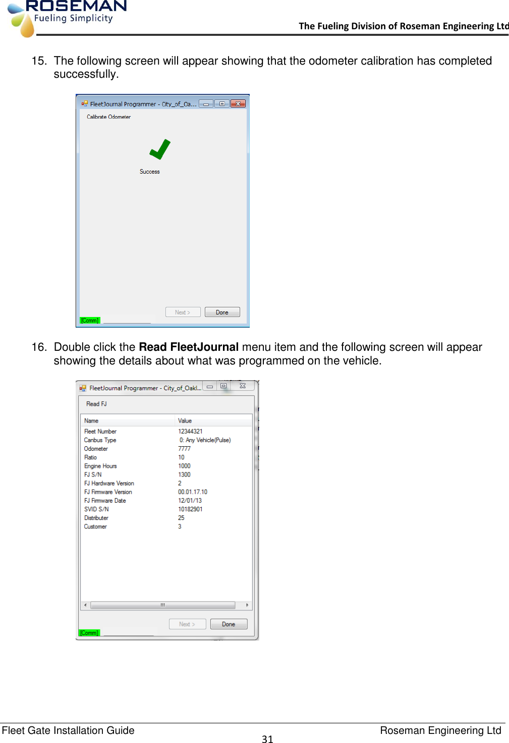
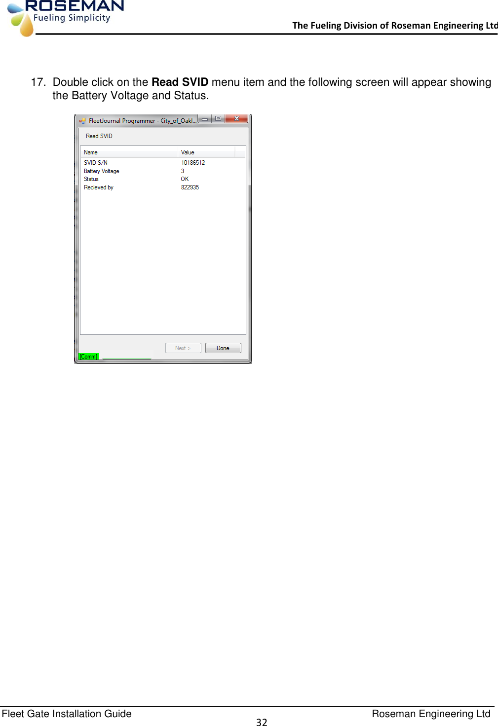
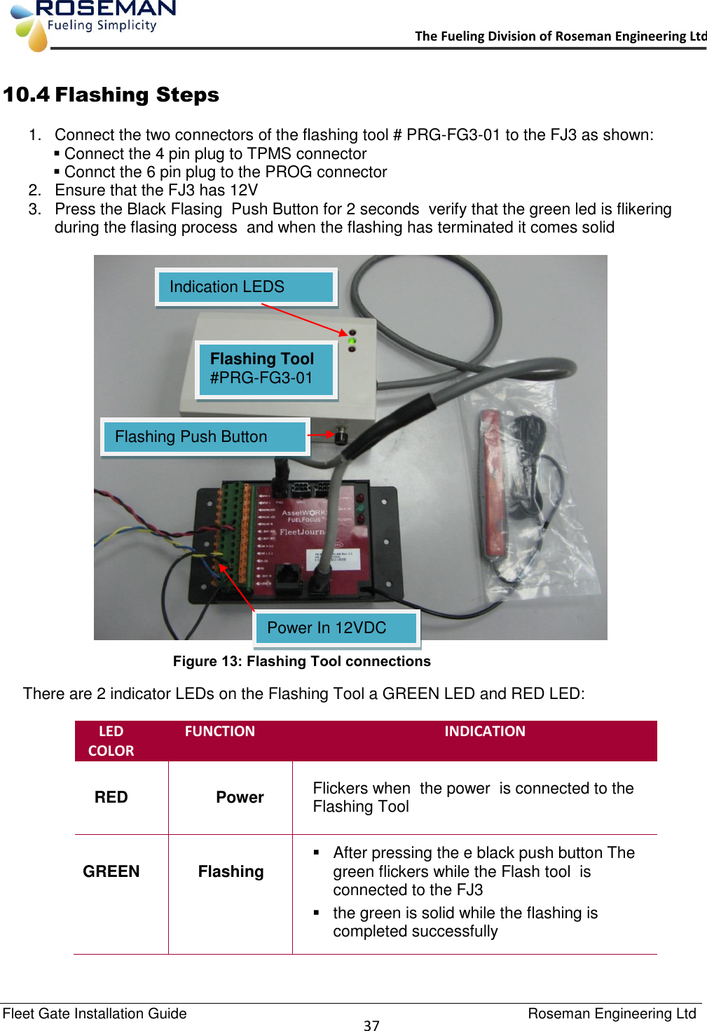
![Fleet Gate Installation Guide Roseman Engineering Ltd 28 The Fueling Division of Roseman Engineering Ltd. 9.2 Programming Steps 1. The Main Menu screen appears showing the following menu items: Program Vehicle Read FleetJournal Read SVID Calibrate Vehicle Update FleetJournal Firmware 2. Verify the WAF is connected [comm] shows green. 3. Single click on the Program Vehicle menu item and the following screen appears showing the devices serial numbers that are in range of the antenna. 4. Select the FJ3 Serial Number that you want to program and single click on it. 5. Click Next to continue.](https://usermanual.wiki/Roseman-Engineering/FG3E.Users-Manual/User-Guide-2550431-Page-28.png)