Roseman Engineering WNR24 Wireless Nozzle Reader User Manual
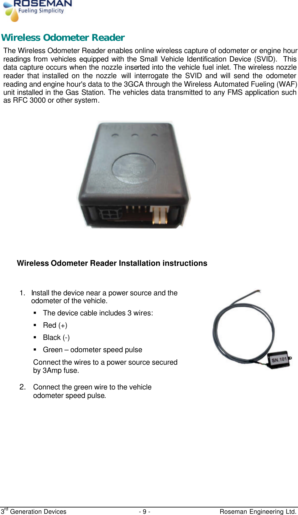
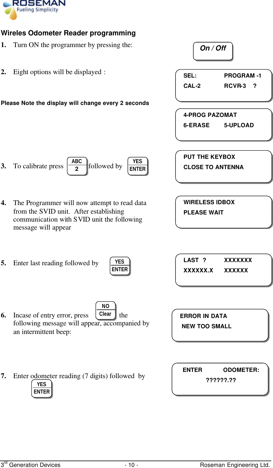
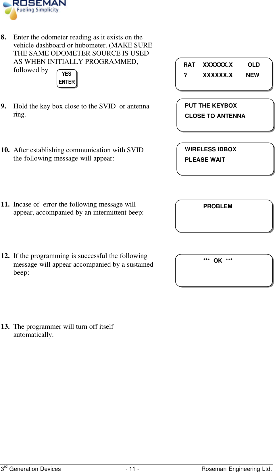
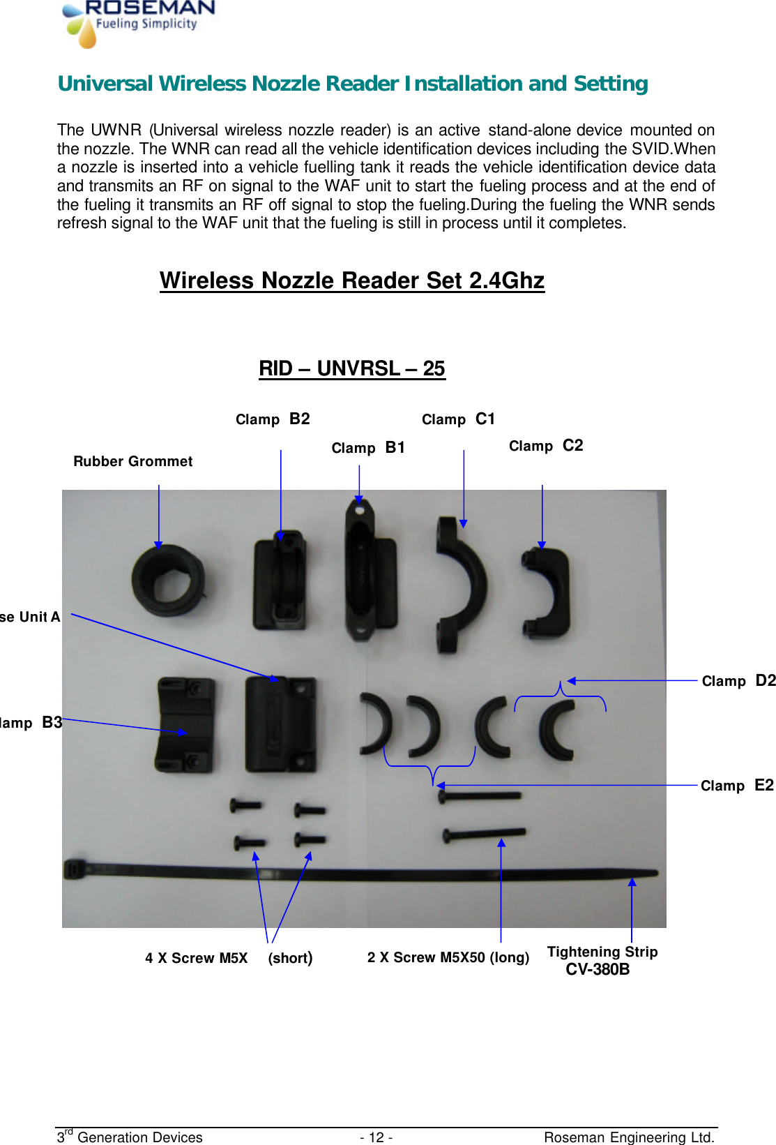
Roseman Engineering Ltd. Wireless Nozzle Reader Users Manual
UserManual.wiki
>
Roseman Engineering
>
WNR24 User Manual
Users Manual
Navigation menu
Upload a User Manual
Namespaces
Wiki Guide
HTML
PDF
Info
Views
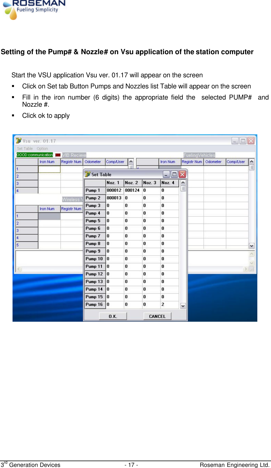
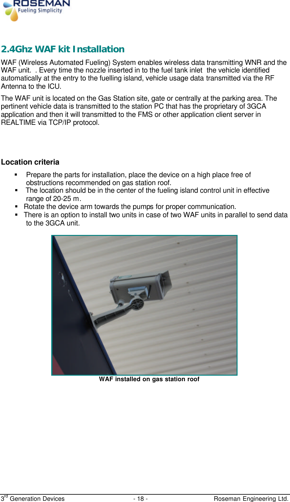
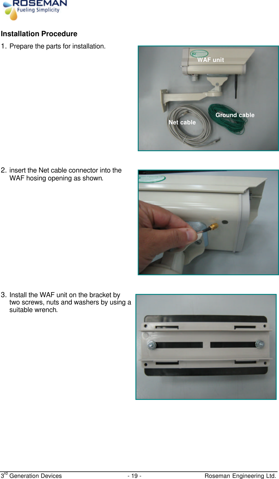
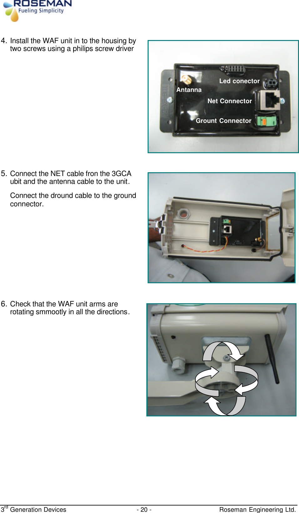
User Manual
Discussion / Help
Navigation
![3rd Generation Devices - 26 - Roseman Engineering Ltd. 10. Now the 3GCA / RFU ready to use. 11. Edit the Vsu.ini [general] Chk_Port=1 tcpip_port=3006 // Customer Server Interface Port write_log=3 max_coms=2 keep_seconds=30 Com_rf1=1 // Com Port com_rf2=8 com_rf1_baudrate=28800 com_rf2_baudrate=28000 max_veh=4 debug=y rfc3000=n language=2 2400_MHz =y Rfu24_ServerPort=5007 // Dest Port: Default 5007 Rfu24_Interface=tcp // Tcp-TCP/IP; Com–Cop Port.](https://usermanual.wiki/Roseman-Engineering/WNR24/User-Guide-1026111-Page-26.png)