Roseman Engineering WNR24 Wireless Nozzle Reader User Manual
Roseman Engineering Ltd. Wireless Nozzle Reader Users Manual
Users Manual
3rd Generation Devices
Installation and Programming Guide

3rd Generation Devices - 2 - Roseman Engineering Ltd.
TABLE OF CONTENTS
OVERVIEW .............................................................................................................................................................................4
SVID (SMALL VEHICLE IDENTIFICATION DEVICE).........................................................................................4
SVID INSTALLATION AND PROGRAMMING.........................................................................................................5
SVID LOCATION CRITERIA............................................................................................................................................. 5
SVID INSTALLATION WITH INTERNAL ANTENNA........................................................................................................ 5
SVID INSTALLATION WITH EXTERNAL ANTENNA....................................................................................................... 6
SVID ACTIVATION..............................................................................................................................................................7
RECEIVING DATA FROM THE DEVICE ........................................................................................................................... 8
WIRELESS ODOMETER READER................................................................................................................................9
WIRELESS ODOMETER READER INSTALLATION INSTRUCT IONS................................................................................ 9
WIRELES ODOMETER READER PROGRAMMING......................................................................................................... 10
UNIVERSAL WIRELESS NOZZLE READER INSTALLATION AND SETTING.......................................12
EXAMPLE:INSTALLATION PROCEDURE FOR HEALY 600 .......................................................................................... 13
SETTING OF THE PUMP # & NOZZLE# ON VSU APPLICATION OF THE STATION COMPUTER.................................. 17
2.4GHZ WAF KIT INSTALLATION.............................................................................................................................18
LOCATION CRITERIA....................................................................................................................................................... 18
INSTALLATION PROCEDURE .......................................................................................................................................... 19
GAS STATION INSTALLATION...................................................................................................................................22
3GCA COMMUNICATION ADAPTER............................................................................................................................. 22
3GCA PROG /SETTING....................................................................................................................................................23
CONFIGURATION PROCESS............................................................................................................................................. 23

3rd Generation Devices - 3 - Roseman Engineering Ltd.
The FCC Wants You to Know
This equipment has been tested and found to comply with the limits for a Class
B digital device, pursuant to Part 15 of the FCC rules. These limits are designed
to provide reasonable protection against harmful interference in a residential
installation. This equipment generates, uses and can radiate radio frequency
energy and, if not installed and used in accordance with the instructions, may
cause harmful interference to radio communications. However, there is no
guarantee that interference will not occur in a particular installation. If this
equipment does cause harmful interference to radio or television reception,
which can be determined by turning the equipment off and on, the user is
encouraged to try to correct the interference by one or more of the following
measures:
a) Reorient or relocate the receiving antenna.
b) Increase the separation between the equipment and receiver.
c) Connect the equipment to an outlet on a circuit different from that to
which the receiver is connected.
d) Consult the dealer or an experienced radio/TV technician.
FCC Warning
Modifications not expressly approved by the manufacturer could void the user
authority to operate the equipment under FCC Rules.
This device complies with Part 15 of the FCC Rules. Operation is subject to the
following two conditions:
(1) This device may not cause harmful interference and
(2) This device must accept any interference received,
including interference that may cause undesired
operation.
3rd Generation Devices - 4 - Roseman Engineering Ltd.
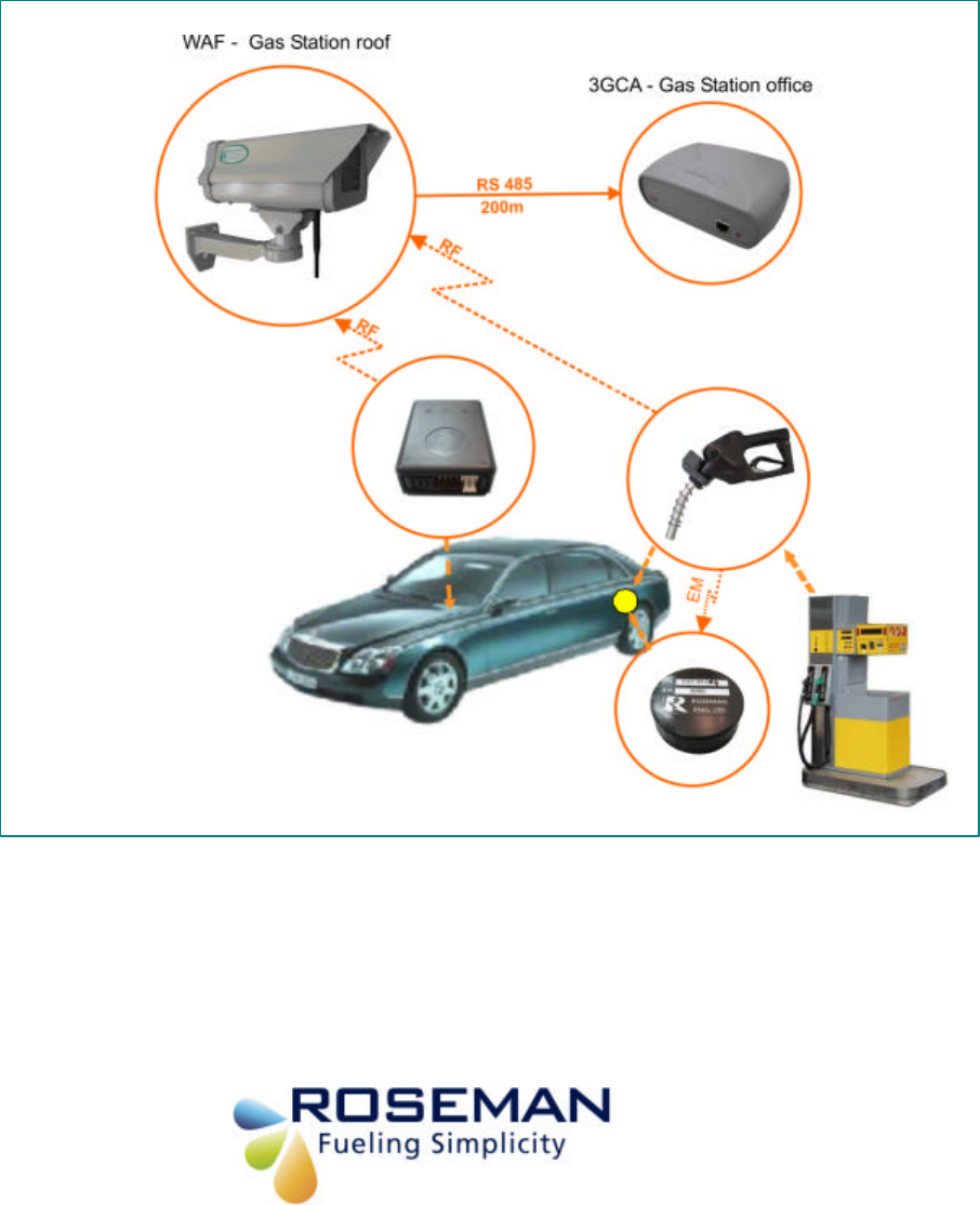
Overview
The 3rd Generation devices comprise wireless Vehicle identification and station identification
devices as follows:
• Vehicle Identification devices includes:
§ SVID Wireless (Small Vehicle Identification Device)
§ Wireless Odometer Reader-VIB
• Station devices includes:
§ Wireless Nozzle Reader (WNR)
§ WAF (Wireless Automated Fueling)
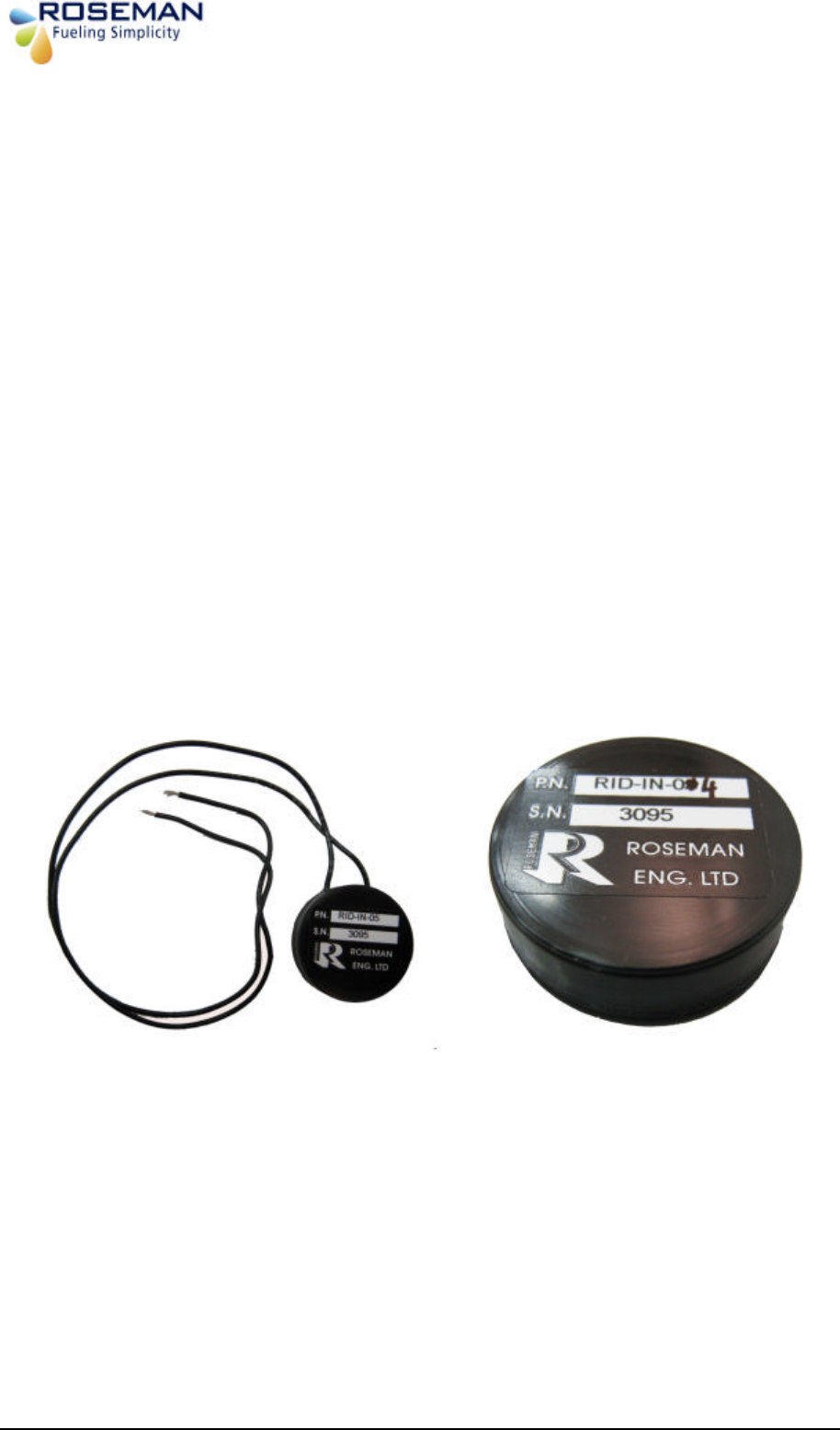
SVID (Small Vehicle Identification Device)
The SVID is a unique vehicle identification device used for automatic fueling.
The SVID is programmed with a unique iron number that can't be changed.
The are two types of devices:
§ SVID with internal antenna
§ SVID with external antenna
SVID with external antenna
wires ANTENNA WIRES
SVID with internal antenna
3rd Generation Devices - 5 - Roseman Engineering Ltd.
SVID Installation and programming
The installation is easy and simple and doesn't require any wiring work.
SVID Location criteria
The location of the SVID will be determined according to the device type:
§ SVID with internal antenna will be located as near as possible to the fueling tank.
§ SVID with external antenna will be located in the vehicle trunk behind the fueling tank.
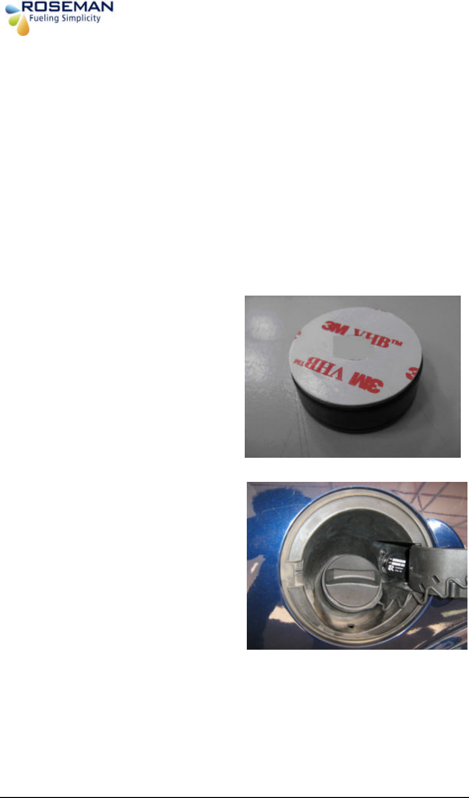
SVID Installation with internal antenna
Remove the sticker underneath the device
Stick the device in the fueling tank
compartment near the fueling tank
?????
sticker
Device Installed
3rd Generation Devices - 6 - Roseman Engineering Ltd.
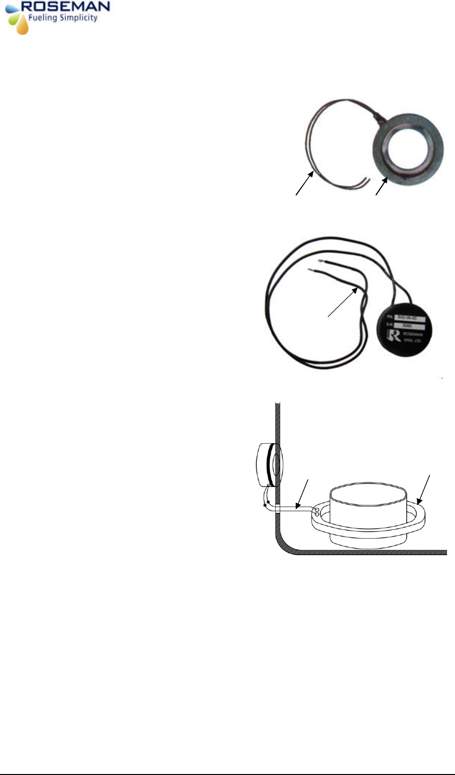
SVID Installation with external antenna
1. Install the antenna ring on the fuel tank
inlet. Select a ring according to the vehicle
type.
2. Install the SVID vehicle trunk behind the
fueling tank the fuel inlet.
3. Connect the SVID antenna wres with
Antenna ring wires using two suitable
connectors.
Antenna Ring
Vehicle trunk Fueling compartment
Fuel inlet
SVID
Antenna wires
Antenna wires
Antenna Ring
Antenna wires
3rd Generation Devices - 7 - Roseman Engineering Ltd.
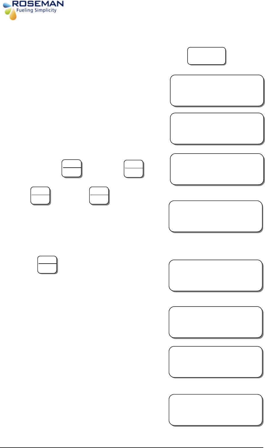
SVID Activation
1. Turn ON the programmer by pressing the:
2. Eight options will be displayed :
Please Note the display will change every 2 seconds
3. To activate press followed by
4. Press followed by
The Programmer will now attempt to read data
from the SVID unit. After establishing
communication with SVID unit the following
message will appear
5. Press
6. Hold the key box close to the SVID or antenna
ring .After establishing communication with
SVID the following message will appear:
7. Incase of error the following message will
appear, accompanied by an intermittent beep:
8. If the programming is successful the following
message will appear accompanied by a sustained
beep:
9. The programmer will turn off itself
automatically.
On / Off
SEL:
PROGRAM
-
1
CAL-2 RCVR-3 ?
4
-
PROG PAZOMAT
6-ERASE 5-UPLOAD
IDBOX
-
0
DIARY
-
1
INTERO – 2 ?
1
YES
ENTER
WIRELESS IDBOX
PLEASE WAIT
IDBOX CABLE
SEL ?
ABC
2
YES
ENTER
PUT THE KEYBOX
CLOSE TO ANTENNA
NO
Clear
PROBLEM
*** OK ***
3rd Generation Devices - 8 - Roseman Engineering Ltd.
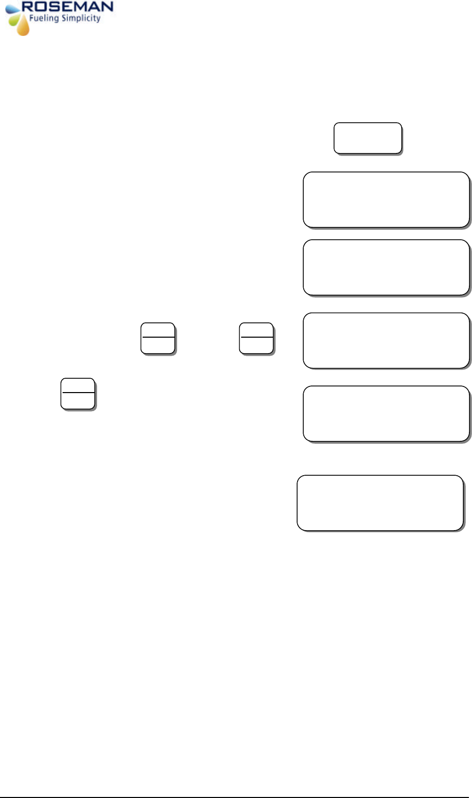
Receiving Data from the Device
1. Turn ON the programmer by pressing the:
2. Eight options will be displayed :
Please Note the display will change every 2 seconds
3. To receive data press followed by
4. Press
5. Hold the keybox close to the SVID.The
follwing meassage will appear.
On / Off
SEL:
PROGRAM
-
1
CAL-2 RCVR-3 ?
4
-
PROG PAZOMAT
6-ERASE 5-UPLOAD
7
-
CHANGE FUEL
8-GENERAL
YES
ENTER
PUT THE KEYBOX
CLOSE TO ANTENNA
ABC
2
IRON N
O:XXXX
XXX
X
102 BATTERY: X.X (Volts)
NO
CLEAR
3rd Generation Devices - 9 - Roseman Engineering Ltd.
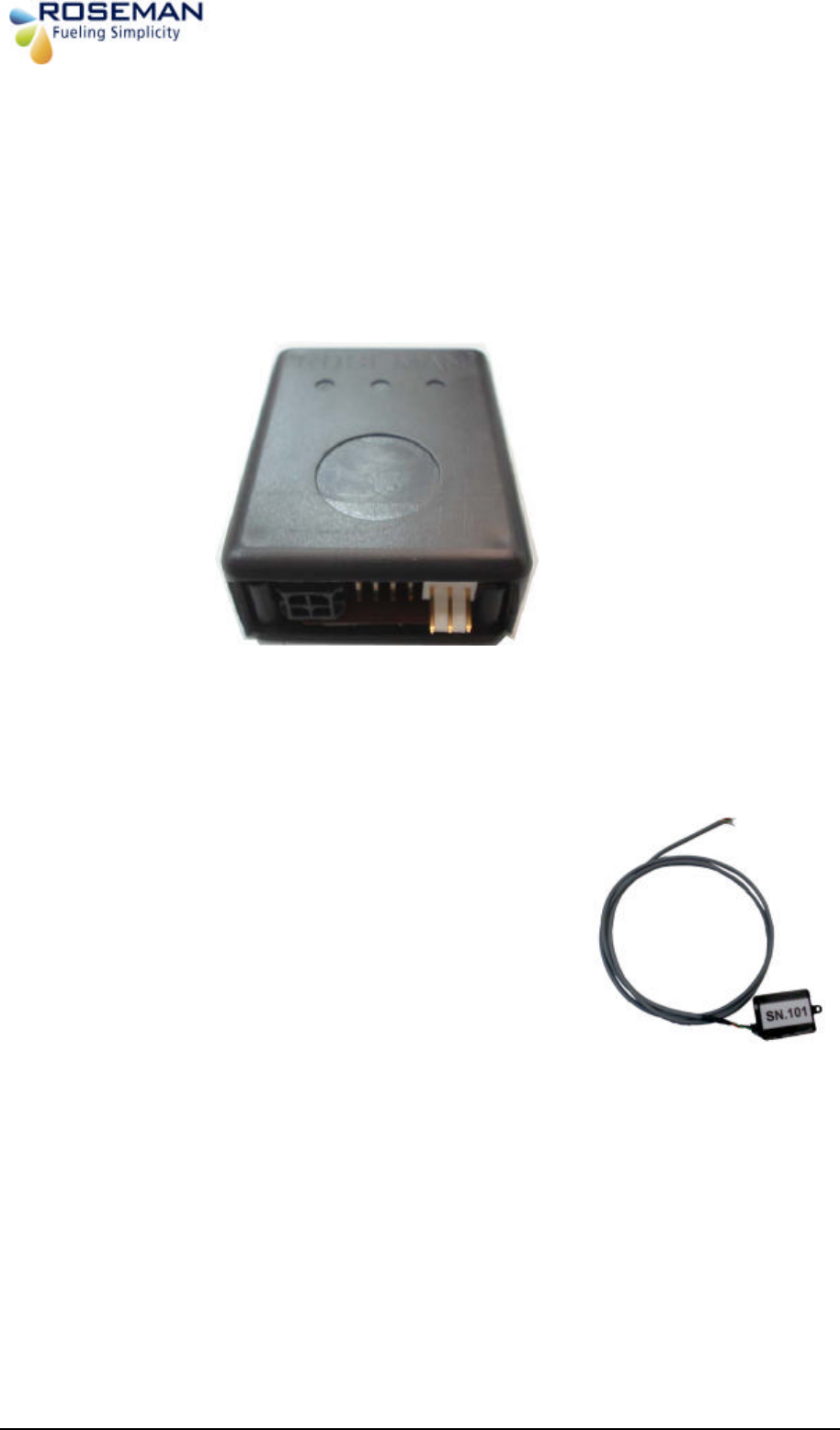
Wireless Odometer Reader
The Wireless Odometer Reader enables online wireless capture of odometer or engine hour
readings from vehicles equipped with the Small Vehicle Identification Device (SVID). This
data capture occurs when the nozzle inserted into the vehicle fuel inlet. The wireless nozzle
reader that installed on the nozzle will interrogate the SVID and will send the odometer
reading and engine hour's data to the 3GCA through the Wireless Automated Fueling (WAF)
unit installed in the Gas Station. The vehicles data transmitted to any FMS application such
as RFC 3000 or other system.
Wireless Odometer Reader Installation instructions
1. Install the device near a power source and the
odometer of the vehicle.
§ The device cable includes 3 wires:
§ Red (+)
§ Black (-)
§ Green – odometer speed pulse
Connect the wires to a power source secured
by 3Amp fuse.
2. Connect the green wire to the vehicle
odometer speed pulse.
3rd Generation Devices - 10 - Roseman Engineering Ltd.
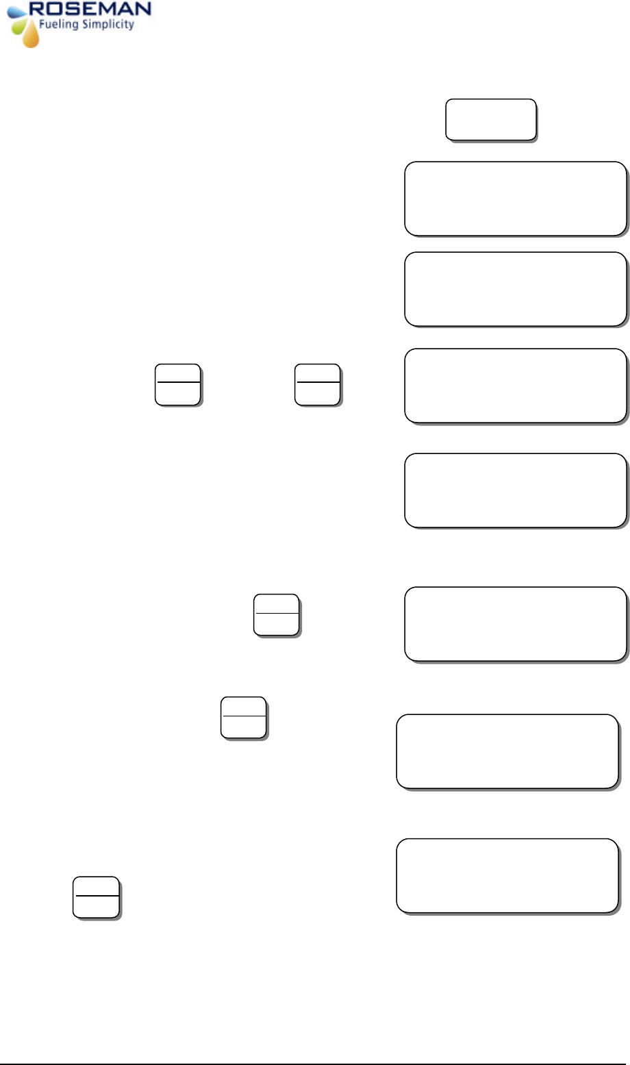
Wireles Odometer Reader programming
1. Turn ON the programmer by pressing the:
2. Eight options will be displayed :
Please Note the display will change every 2 seconds
3. To calibrate press followed by
4. The Programmer will now attempt to read data
from the SVID unit. After establishing
communication with SVID unit the following
message will appear
5. Enter last reading followed by
6. Incase of entry error, press the
following message will appear, accompanied by
an intermittent beep:
7. Enter odometer reading (7 digits) followed by
On / Off
SEL:
PROGRAM
-
1
CAL-2 RCVR-3 ?
4
-
PROG PAZOMAT
6-ERASE 5-UPLOAD
PUT THE KEYBOX
CLOSE TO ANTENNA
ABC
2
YES
ENTER
WIRELESS IDBOX
PLEASE WAIT
LAST
?
XXXXXXX
XXXXXX.X XXXXXX
YES
ENTER
ERROR IN DATA
NEW TOO SMALL
NO
Clear
ENTER
ODOMETER:
??????.??
YES
ENTER
3rd Generation Devices - 11 - Roseman Engineering Ltd.
8. Enter the odometer reading as it exists on the
vehicle dashboard or hubometer. (MAKE SURE
THE SAME ODOMETER SOURCE IS USED
AS WHEN INITIALLY PROGRAMMED,
followed by
9. Hold the key box close to the SVID or antenna
ring.
10. After establishing communication with SVID
the following message will appear:
11. Incase of error the following message will
appear, accompanied by an intermittent beep:
12. If the programming is successful the following
message will appear accompanied by a sustained
beep:
13. The programmer will turn off itself
automatically.
RAT
XXXXXX.X
OLD
? XXXXXX.X NEW
YES
ENTER
PUT THE KEYBOX
CLOSE TO ANTENNA
WIRELESS IDBOX
PLEASE WAIT
PROBLEM
*** OK ***
3rd Generation Devices - 12 - Roseman Engineering Ltd.
Universal Wireless Nozzle Reader Installation and Setting
The UWNR (Universal wireless nozzle reader) is an active stand-alone device mounted on
the nozzle. The WNR can read all the vehicle identification devices including the SVID.When
a nozzle is inserted into a vehicle fuelling tank it reads the vehicle identification device data
and transmits an RF on signal to the WAF unit to start the fueling process and at the end of
the fueling it transmits an RF off signal to stop the fueling.During the fueling the WNR sends
refresh signal to the WAF unit that the fueling is still in process until it completes.
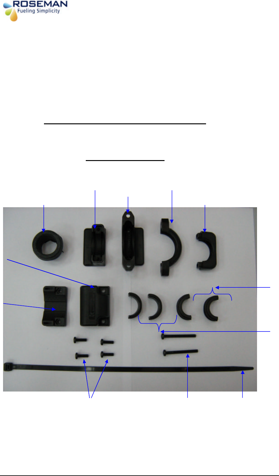
Wireless Nozzle Reader Set 2.4Ghz
RID – UNVRSL – 25
Clamp
D2
Clamp
E2
R
ubber Grommet
Clamp
B1
Clamp
C2
4 X Screw M5X (short)
2 X Screw M5X50 (long)
Tight
ening Strip
CV-380B
lamp
B3
Base Unit
A
Clamp
B2
Clamp
C1
3rd Generation Devices - 13 - Roseman Engineering Ltd.
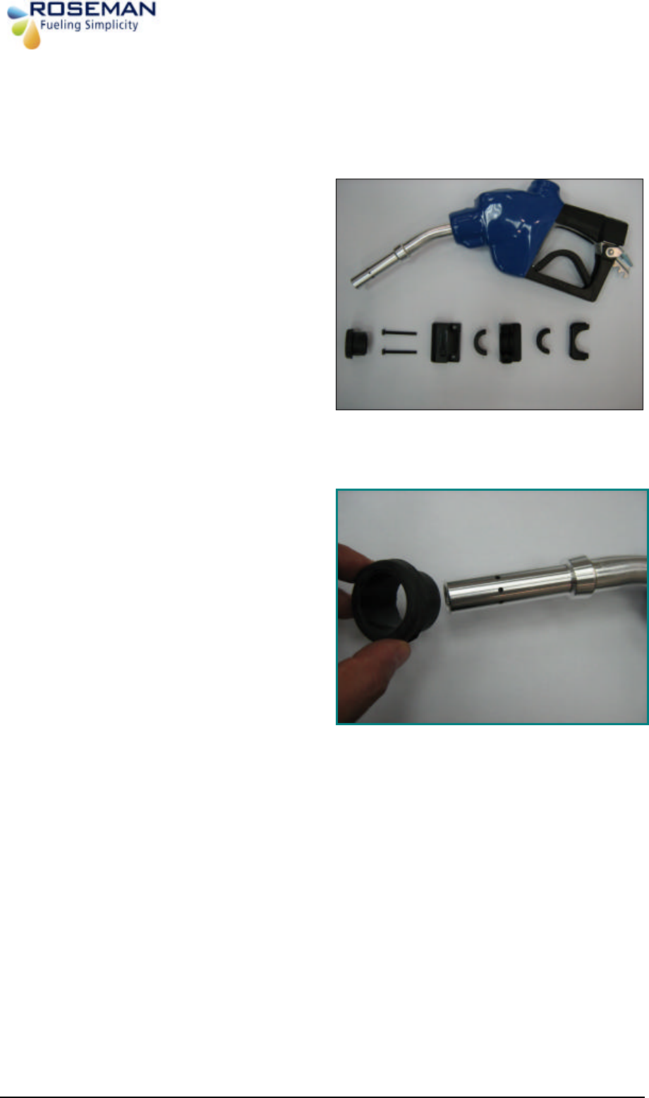
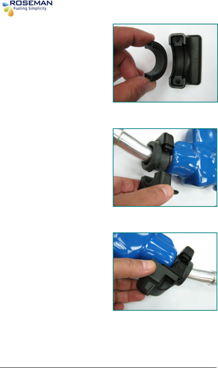
Example:Installation Procedure for Healy 600
Step 1:
Prepare the parts for installation
Step 2:
Install the rubber grommet on the
nozzle pipe.
/4
" Nozzle Guard
Attaching screws
3rd Generation Devices - 14 - Roseman Engineering Ltd.
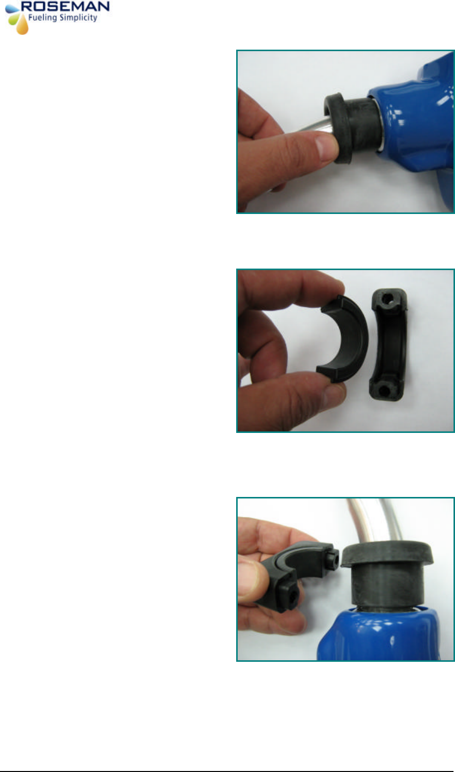
Step :
Insert the rubber grommet into the
nozzle neck.
Step 4:
Install clamp D2 into clamp C2.
Step 5:
Install clamp assembly (C2+D2) on the
rubber grommet.
3rd Generation Devices - 15 - Roseman Engineering Ltd.
Step 6:
Install clamp D2 into clamp B2.
Step 7:
Attach the sub assembly (C2+D2) to
(B2+D2) sub assembly on the rubber
grommet from the opposite side while
the two screw holes are aligned on
both sub assemblies.
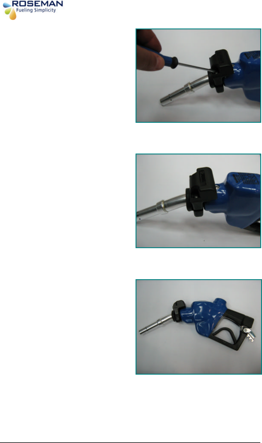
Step 8:
The two assembly part are attached
insert two screws M5X16 (short)
3rd Generation Devices - 16 - Roseman Engineering Ltd.
Step 8:
Install the two screws M5X16 (short)
using a Philips screw driver.
Step 10:
Completion of Installation front view.
Step 11:
Completion of Installation side view.
3rd Generation Devices - 17 - Roseman Engineering Ltd.
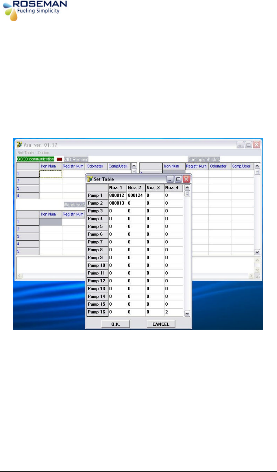
Setting of the Pump# & Nozzle# on Vsu application of the station computer
Start the VSU application Vsu ver. 01.17 will appear on the screen
§ Click on Set tab Button Pumps and Nozzles list Table will appear on the screen
§ Fill in the iron number (6 digits) the appropriate field the selected PUMP# and
Nozzle #.
§ Click ok to apply
3rd Generation Devices - 18 - Roseman Engineering Ltd.
2.4Ghz WAF kit Installation
WAF (Wireless Automated Fueling) System enables wireless data transmitting WNR and the
WAF unit. . Every time the nozzle inserted in to the fuel tank inlet the vehicle identified
automatically at the entry to the fuelling island, vehicle usage data transmitted via the RF
Antenna to the ICU.
The WAF unit is located on the Gas Station site, gate or centrally at the parking area. The
pertinent vehicle data is transmitted to the station PC that has the proprietary of 3GCA
application and then it will transmitted to the FMS or other application client server in
REALTIME via TCP/IP protocol.
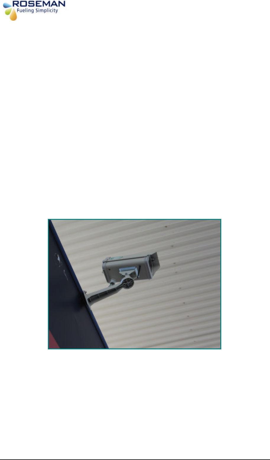
Location criteria
§ Prepare the parts for installation, place the device on a high place free of
obstructions recommended on gas station roof.
§ The location should be in the center of the fueling island control unit in effective
range of 20-25 m.
§ Rotate the device arm towards the pumps for proper communication.
§ There is an option to install two units in case of two WAF units in parallel to send data
to the 3GCA unit.
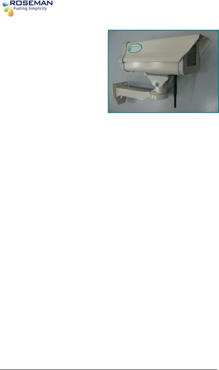
WAF installed on gas station roof
3rd Generation Devices - 19 - Roseman Engineering Ltd.
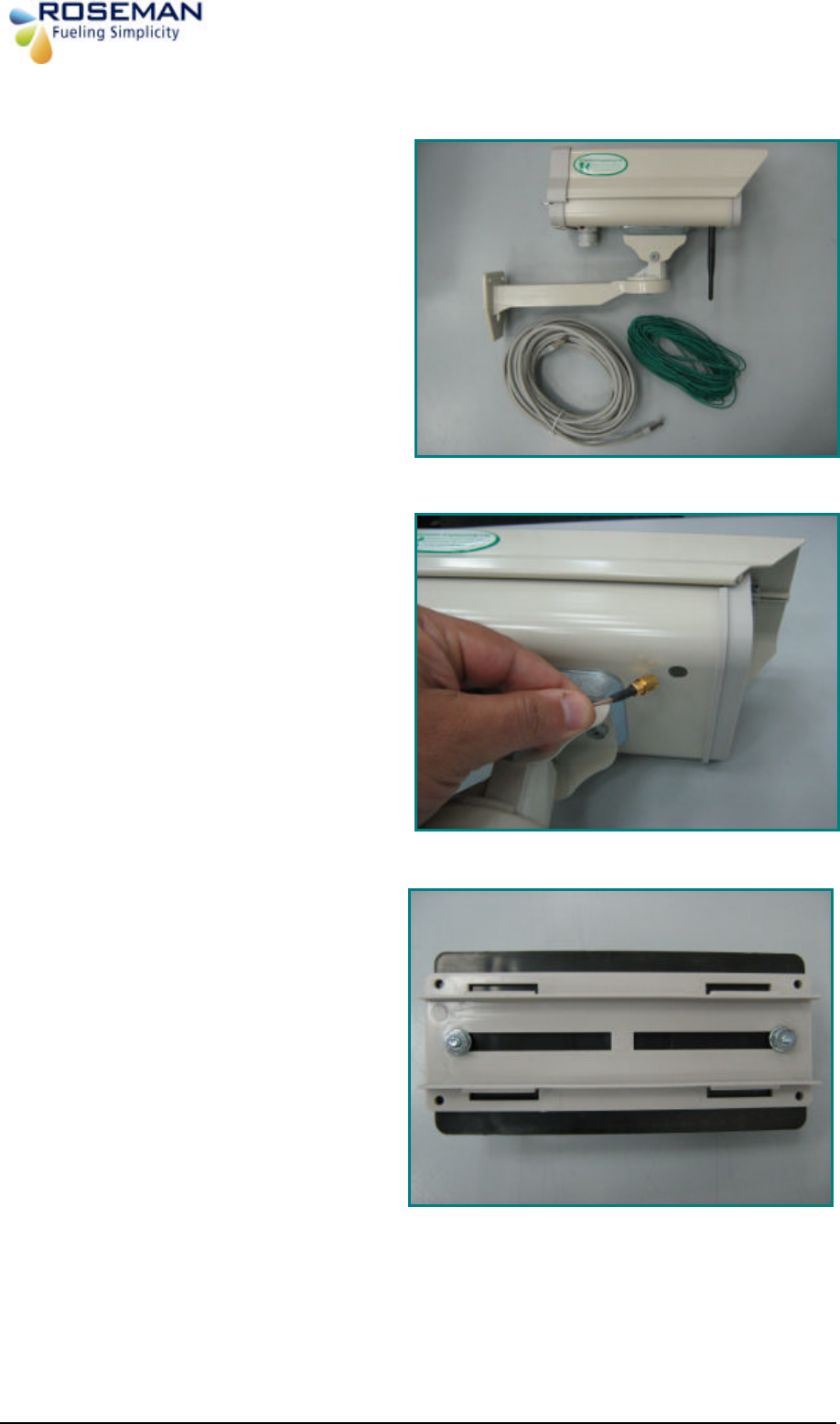
Installation Procedure
1. Prepare the parts for installation.
2. insert the Net cable connector into the
WAF hosing opening as shown.
3. Install the WAF unit on the bracket by
two screws, nuts and washers by using a
suitable wrench.
Net cable Ground cable
WAF unit
3rd Generation Devices - 20 - Roseman Engineering Ltd.
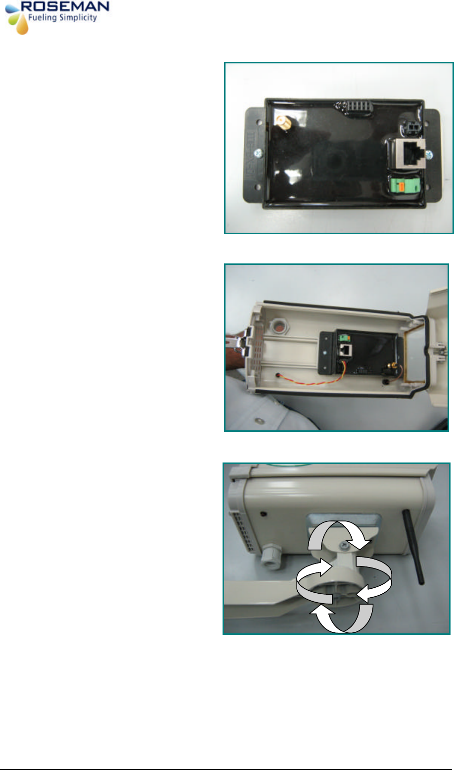
4. Install the WAF unit in to the housing by
two screws using a philips screw driver
5. Connect the NET cable fron the 3GCA
ubit and the antenna cable to the unit.
Connect the dround cable to the ground
connector.
6. Check that the WAF unit arms are
rotating smmootly in all the directions.
Antanna
Led conector
Net Connector
Grount Connector
3rd Generation Devices - 21 - Roseman Engineering Ltd.
7. End of installation.
3rd Generation Devices - 22 - Roseman Engineering Ltd.
Gas Station installation
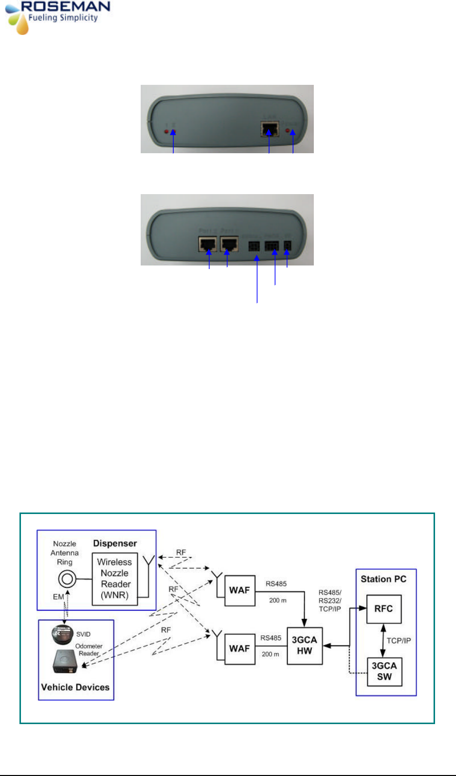
3GCA Communication Adapter
The 3G Communication Adapter (3GCA) is vehicle detection and data collection unit
that works in conjunction with the WAF unit and enables to identify automatically the
wireless devices on the gas station.
The 3GCA have three serial ports: two for WAF unit and one to station PC. It can work with
two WAF units at the same time.
The two RS 485 isolated serial ports (Port 1 & Port 2); designed to receives the wireless
nozzle reader (WNR) data on the fuel pump dispenser and the odometer reader data from
the vehicle via the WAF units that located in a high place at the gas station area.
The 3GCA hardware may have two models, one-model functions as an adapter from RS485
to TCP/IP with 3GCA software running on the station PC, and the other model functions as a
standalone data collector for other applications.
LAN-Port 3 to PC
Front
Rear
Serial RS232/RS485
Power LED
Power 5V
Prog.
Port 1, 2 LEDS
Port 2 Port 1
2 X RS485 to WAF
3rd Generation Devices - 23 - Roseman Engineering Ltd.
3GCA PROG /SETTING
Connect the hardware as described on the above diagram.
Configuration process
1. Connect serial Net cable from the PC to the 3GCA LAN port3.
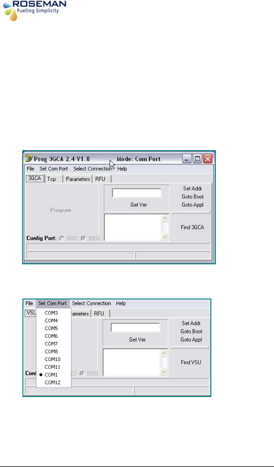
2. Start the application "Prog3GCA2.4.exe" Main screen will appear.
3. Select "Set Com Port"
3rd Generation Devices - 24 - Roseman Engineering Ltd.
4. "select connection type", select Com Port
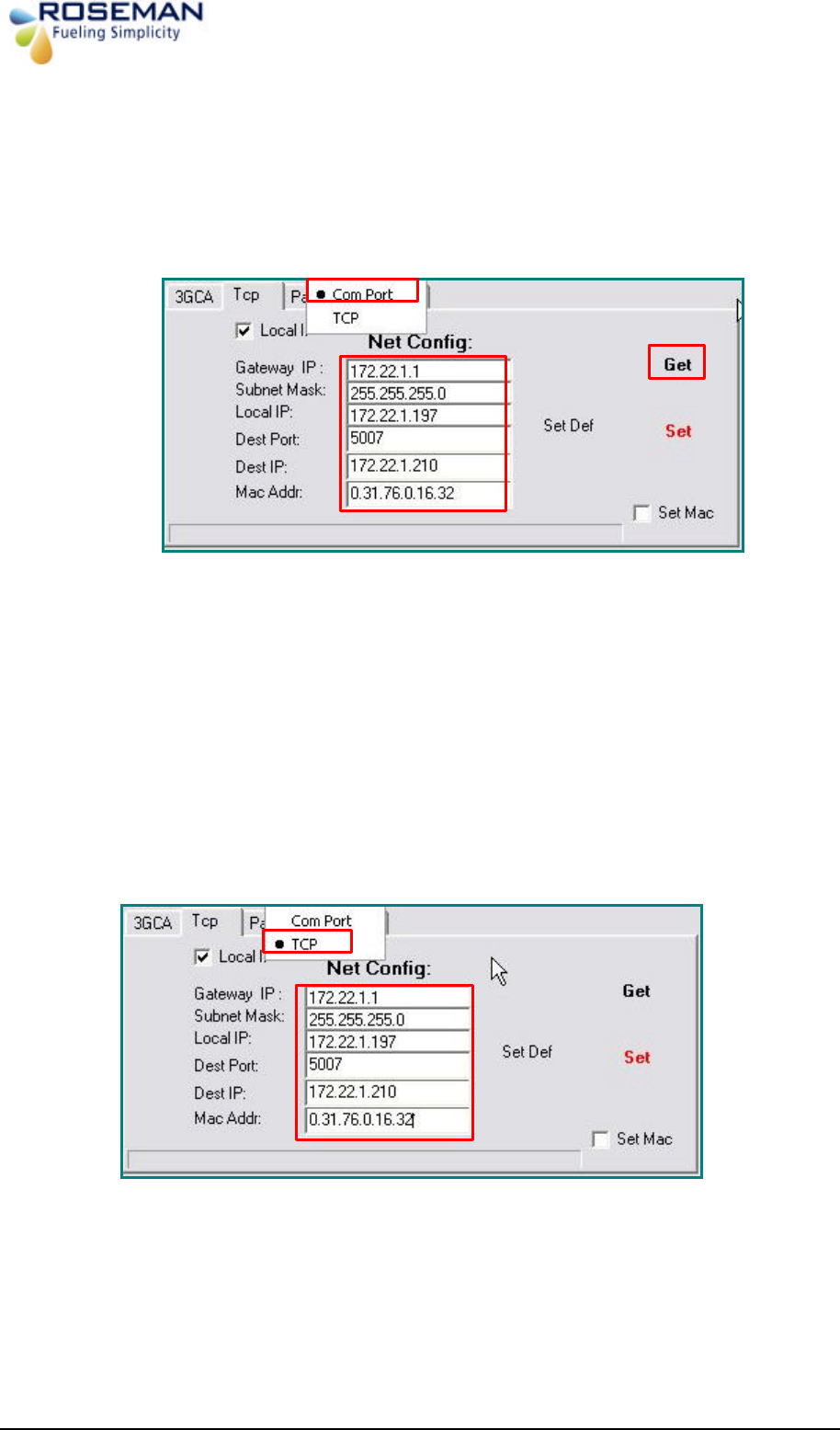
5. Press Get button "Net Config" will display the 3GCA TCP/IP setting.
• Gateway IP: Use default
• Subnet Mask: Class C (As your local Network)
• Local IP: 3GCA Hardware IP.
• Dest Port: Default 5007 (same As vsu.ini)
• Dest IP: Server IP (Where VSU software running from)
• Mac Addr: 3GCA hardware Mac Address. (Do Not Change)
• Configure 3GCA TCP/IP Setting
6. "Select connection type", select TCP
3rd Generation Devices - 25 - Roseman Engineering Ltd.
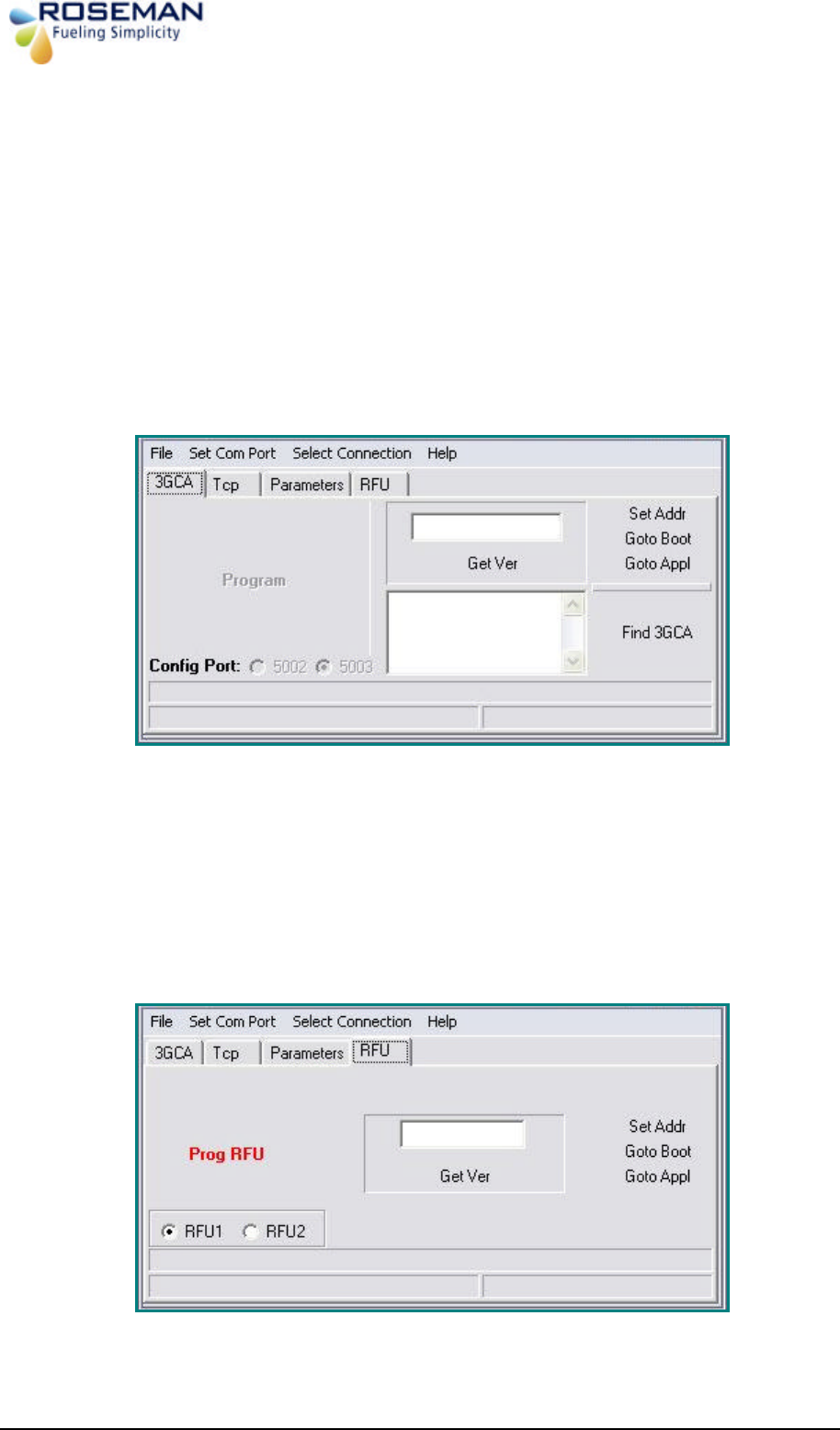
7. For Test configuration Press Get button to receive IP setting.
8. 3GCA Tab will display:
• 3GCA Version (Press Get Ver.)
• 3GCA IP (Press Find VSU)
• To Program VSU Version, Press File > Open > select the File and Press
Program Button. (Will be Enable)
9. Select and press RFU Tab the following screen will appear:
• RFU Hardware Ver. (Press Get Ver.)
• To Program RFU Version, Press File > Open > select the File and Press
Prog RFU. (Will be Enable).

3rd Generation Devices - 26 - Roseman Engineering Ltd.
10. Now the 3GCA / RFU ready to use.
11. Edit the Vsu.ini
[general]
Chk_Port=1
tcpip_port=3006 // Customer Server Interface Port
write_log=3
max_coms=2
keep_seconds=30
Com_rf1=1 // Com Port
com_rf2=8
com_rf1_baudrate=28800
com_rf2_baudrate=28000
max_veh=4
debug=y
rfc3000=n
language=2
2400_MHz =y
Rfu24_ServerPort=5007 // Dest Port: Default 5007
Rfu24_Interface=tcp // Tcp-TCP/IP; Com–Cop Port.