Rosemount Tank Radar 5408L Rosemount 5408 Level Transmitter User Manual
Rosemount Tank Radar AB Rosemount 5408 Level Transmitter
Contents
- 1. manual part2
- 2. manual part1
manual part1
Reference Manual
00809-0100-4408, Rev AA
November 2016
PRELIMINARY
Rosemount™ 5408 and 5408:SIS Level
Transmitters
Non-Contacting Radar
PRELIMINARY

iii
Reference Manual
00809-0100-4408, Rev AA
Table of Contents
November 2016
Table of Contents
PRELIMINARY
1Section 1: Introduction
1.1 Models covered . . . . . . . . . . . . . . . . . . . . . . . . . . . . . . . . . . . . . . . . . . . . . . . . . . . . . . . 1
1.2 Using this manual. . . . . . . . . . . . . . . . . . . . . . . . . . . . . . . . . . . . . . . . . . . . . . . . . . . . . . 1
1.3 Product recycling/disposal . . . . . . . . . . . . . . . . . . . . . . . . . . . . . . . . . . . . . . . . . . . . . .2
2Section 2: Transmitter Overview
2.1 Measurement principle. . . . . . . . . . . . . . . . . . . . . . . . . . . . . . . . . . . . . . . . . . . . . . . . . 3
2.2 Process characteristics . . . . . . . . . . . . . . . . . . . . . . . . . . . . . . . . . . . . . . . . . . . . . . . . .4
2.2.1 Dielectric constant . . . . . . . . . . . . . . . . . . . . . . . . . . . . . . . . . . . . . . . . . . . . . . . 4
2.2.2 Foam and turbulence. . . . . . . . . . . . . . . . . . . . . . . . . . . . . . . . . . . . . . . . . . . . . 4
2.2.3 Condensation . . . . . . . . . . . . . . . . . . . . . . . . . . . . . . . . . . . . . . . . . . . . . . . . . . . 4
2.3 Vessel characteristics . . . . . . . . . . . . . . . . . . . . . . . . . . . . . . . . . . . . . . . . . . . . . . . . . . 4
2.3.1 In-tank obstructions. . . . . . . . . . . . . . . . . . . . . . . . . . . . . . . . . . . . . . . . . . . . . . 4
2.3.2 Tank shape . . . . . . . . . . . . . . . . . . . . . . . . . . . . . . . . . . . . . . . . . . . . . . . . . . . . . . 5
2.4 Application examples . . . . . . . . . . . . . . . . . . . . . . . . . . . . . . . . . . . . . . . . . . . . . . . . . . 5
2.5 Components of the transmitter . . . . . . . . . . . . . . . . . . . . . . . . . . . . . . . . . . . . . . . . .7
2.6 System integration . . . . . . . . . . . . . . . . . . . . . . . . . . . . . . . . . . . . . . . . . . . . . . . . . . . . 8
3Section 3: Mechanical Installation
3.1 Safety messages. . . . . . . . . . . . . . . . . . . . . . . . . . . . . . . . . . . . . . . . . . . . . . . . . . . . . . .9
3.2 Review mounting considerations . . . . . . . . . . . . . . . . . . . . . . . . . . . . . . . . . . . . . . .10
3.2.1 Mounting position . . . . . . . . . . . . . . . . . . . . . . . . . . . . . . . . . . . . . . . . . . . . . . 10
3.2.2 Antenna size . . . . . . . . . . . . . . . . . . . . . . . . . . . . . . . . . . . . . . . . . . . . . . . . . . . 11
3.2.3 Inclination of antenna . . . . . . . . . . . . . . . . . . . . . . . . . . . . . . . . . . . . . . . . . . .11
3.2.4 Non-metallic tanks . . . . . . . . . . . . . . . . . . . . . . . . . . . . . . . . . . . . . . . . . . . . . . 11
3.2.5 Beam width and beam angle . . . . . . . . . . . . . . . . . . . . . . . . . . . . . . . . . . . . . 12
3.2.6 Nozzle requirements . . . . . . . . . . . . . . . . . . . . . . . . . . . . . . . . . . . . . . . . . . . . 13
3.2.7 Free space requirements . . . . . . . . . . . . . . . . . . . . . . . . . . . . . . . . . . . . . . . . . 15
3.2.8 Installation in still pipe/chamber . . . . . . . . . . . . . . . . . . . . . . . . . . . . . . . . . .16
3.2.9 Ball valve installation . . . . . . . . . . . . . . . . . . . . . . . . . . . . . . . . . . . . . . . . . . . .17
3.3 Review mounting preparations . . . . . . . . . . . . . . . . . . . . . . . . . . . . . . . . . . . . . . . . .18
3.3.1 Assemble the segmented cone antenna . . . . . . . . . . . . . . . . . . . . . . . . . . .18
3.3.2 Shorten the extended cone antenna. . . . . . . . . . . . . . . . . . . . . . . . . . . . . . . 20
3.4 Mount the cone antenna . . . . . . . . . . . . . . . . . . . . . . . . . . . . . . . . . . . . . . . . . . . . . .21
3.4.1 Flanged version . . . . . . . . . . . . . . . . . . . . . . . . . . . . . . . . . . . . . . . . . . . . . . . . .22
3.4.2 Flanged version with air purge ring . . . . . . . . . . . . . . . . . . . . . . . . . . . . . . . .23
Contents

iv
Reference Manual
00809-0100-4408, Rev AA
Table of Contents
November 2016
Table of Contents
PRELIMINARY
3.4.3 Threaded version . . . . . . . . . . . . . . . . . . . . . . . . . . . . . . . . . . . . . . . . . . . . . . . 25
3.4.4 Bracket mounting. . . . . . . . . . . . . . . . . . . . . . . . . . . . . . . . . . . . . . . . . . . . . . .31
3.4.5 Align transmitter head. . . . . . . . . . . . . . . . . . . . . . . . . . . . . . . . . . . . . . . . . . . 34
3.5 Mount the parabolic antenna . . . . . . . . . . . . . . . . . . . . . . . . . . . . . . . . . . . . . . . . . .36
3.5.1 Flanged version . . . . . . . . . . . . . . . . . . . . . . . . . . . . . . . . . . . . . . . . . . . . . . . . .37
3.5.2 Threaded version . . . . . . . . . . . . . . . . . . . . . . . . . . . . . . . . . . . . . . . . . . . . . . . 38
3.5.3 Welded version . . . . . . . . . . . . . . . . . . . . . . . . . . . . . . . . . . . . . . . . . . . . . . . . .42
3.5.4 Adjust the inclination of the antenna . . . . . . . . . . . . . . . . . . . . . . . . . . . . . . 48
3.5.5 Connect the air purging. . . . . . . . . . . . . . . . . . . . . . . . . . . . . . . . . . . . . . . . . . 51
3.6 Adjust display orientation (optional) . . . . . . . . . . . . . . . . . . . . . . . . . . . . . . . . . . . .52
4Section 4: Electrical Installation
4.1 Safety messages. . . . . . . . . . . . . . . . . . . . . . . . . . . . . . . . . . . . . . . . . . . . . . . . . . . . . .53
4.2 Cable selection . . . . . . . . . . . . . . . . . . . . . . . . . . . . . . . . . . . . . . . . . . . . . . . . . . . . . . .54
4.3 Cable gland/conduit . . . . . . . . . . . . . . . . . . . . . . . . . . . . . . . . . . . . . . . . . . . . . . . . . .54
4.4 Power supply. . . . . . . . . . . . . . . . . . . . . . . . . . . . . . . . . . . . . . . . . . . . . . . . . . . . . . . . .54
4.5 Hazardous areas . . . . . . . . . . . . . . . . . . . . . . . . . . . . . . . . . . . . . . . . . . . . . . . . . . . . . .54
4.6 Wiring diagram. . . . . . . . . . . . . . . . . . . . . . . . . . . . . . . . . . . . . . . . . . . . . . . . . . . . . . .55
4.7 Grounding . . . . . . . . . . . . . . . . . . . . . . . . . . . . . . . . . . . . . . . . . . . . . . . . . . . . . . . . . . .55
4.7.1 Transmitter housing. . . . . . . . . . . . . . . . . . . . . . . . . . . . . . . . . . . . . . . . . . . . . 55
4.7.2 Signal cable shield grounding. . . . . . . . . . . . . . . . . . . . . . . . . . . . . . . . . . . . .56
4.8 Wiring and power up . . . . . . . . . . . . . . . . . . . . . . . . . . . . . . . . . . . . . . . . . . . . . . . . . .57
4.9 Optional devices. . . . . . . . . . . . . . . . . . . . . . . . . . . . . . . . . . . . . . . . . . . . . . . . . . . . . .60
4.9.1 Rosemount 333 HART Tri-Loop™ . . . . . . . . . . . . . . . . . . . . . . . . . . . . . . . . .60
5Section 5: Configuration
5.1 Safety messages. . . . . . . . . . . . . . . . . . . . . . . . . . . . . . . . . . . . . . . . . . . . . . . . . . . . . .61
5.2 Overview . . . . . . . . . . . . . . . . . . . . . . . . . . . . . . . . . . . . . . . . . . . . . . . . . . . . . . . . . . . .62
5.3 Get started with your preferred configuration tool . . . . . . . . . . . . . . . . . . . . . . . .62
5.3.1 Rosemount Radar Master . . . . . . . . . . . . . . . . . . . . . . . . . . . . . . . . . . . . . . . . 62
5.3.2 AMS Device Manager . . . . . . . . . . . . . . . . . . . . . . . . . . . . . . . . . . . . . . . . . . . . 63
5.3.3 Field Communicator. . . . . . . . . . . . . . . . . . . . . . . . . . . . . . . . . . . . . . . . . . . . .64
5.4 Configure device using Guided Setup . . . . . . . . . . . . . . . . . . . . . . . . . . . . . . . . . . .65
5.5 Verify Level . . . . . . . . . . . . . . . . . . . . . . . . . . . . . . . . . . . . . . . . . . . . . . . . . . . . . . . . . .66
5.6 Establish multidrop communication . . . . . . . . . . . . . . . . . . . . . . . . . . . . . . . . . . . .66
5.7 Use with the HART Tri-Loop . . . . . . . . . . . . . . . . . . . . . . . . . . . . . . . . . . . . . . . . . . . .67

v
Reference Manual
00809-0100-4408, Rev AA
Table of Contents
November 2016
Table of Contents
PRELIMINARY
6Section 6: Operation
6.1 LCD display screen messages. . . . . . . . . . . . . . . . . . . . . . . . . . . . . . . . . . . . . . . . . . .69
6.1.1 Startup screen sequence. . . . . . . . . . . . . . . . . . . . . . . . . . . . . . . . . . . . . . . . .69
6.1.2 Variable screens . . . . . . . . . . . . . . . . . . . . . . . . . . . . . . . . . . . . . . . . . . . . . . . .70
6.2 Set up the LCD display. . . . . . . . . . . . . . . . . . . . . . . . . . . . . . . . . . . . . . . . . . . . . . . . .70
6.3 View measurement data. . . . . . . . . . . . . . . . . . . . . . . . . . . . . . . . . . . . . . . . . . . . . . .71
6.3.1 View current measurement values . . . . . . . . . . . . . . . . . . . . . . . . . . . . . . . .71
6.3.2 Interpret measurement status bars. . . . . . . . . . . . . . . . . . . . . . . . . . . . . . . . 72
6.4 Check device status . . . . . . . . . . . . . . . . . . . . . . . . . . . . . . . . . . . . . . . . . . . . . . . . . . .72
7Section 7: Troubleshooting
7.1 Safety messages. . . . . . . . . . . . . . . . . . . . . . . . . . . . . . . . . . . . . . . . . . . . . . . . . . . . . .75
7.2 Diagnostic messages. . . . . . . . . . . . . . . . . . . . . . . . . . . . . . . . . . . . . . . . . . . . . . . . . .76
7.3 Troubleshooting guide . . . . . . . . . . . . . . . . . . . . . . . . . . . . . . . . . . . . . . . . . . . . . . . .82
7.4 Service and troubleshooting tools . . . . . . . . . . . . . . . . . . . . . . . . . . . . . . . . . . . . . .87
7.4.1 Use the echo curve function . . . . . . . . . . . . . . . . . . . . . . . . . . . . . . . . . . . . . .87
7.4.2 Manage disturbance echoes. . . . . . . . . . . . . . . . . . . . . . . . . . . . . . . . . . . . . .90
7.4.3 Save and load configuration files . . . . . . . . . . . . . . . . . . . . . . . . . . . . . . . . . . 94
7.4.4 Restore to default settings . . . . . . . . . . . . . . . . . . . . . . . . . . . . . . . . . . . . . . .95
7.4.5 Calibrate analog out. . . . . . . . . . . . . . . . . . . . . . . . . . . . . . . . . . . . . . . . . . . . . 95
7.4.6 Use the simulation mode . . . . . . . . . . . . . . . . . . . . . . . . . . . . . . . . . . . . . . . . 96
7.4.7 View input registers . . . . . . . . . . . . . . . . . . . . . . . . . . . . . . . . . . . . . . . . . . . . . 96
7.4.8 View/edit holding registers. . . . . . . . . . . . . . . . . . . . . . . . . . . . . . . . . . . . . . . 97
7.5 Write protect a transmitter . . . . . . . . . . . . . . . . . . . . . . . . . . . . . . . . . . . . . . . . . . . .98
7.6 Application challenges . . . . . . . . . . . . . . . . . . . . . . . . . . . . . . . . . . . . . . . . . . . . . . . .99
7.6.1 Handling disturbances at top of tank . . . . . . . . . . . . . . . . . . . . . . . . . . . . . .99
7.6.2 Tracking of weak surface echoes close to tank bottom. . . . . . . . . . . . . .100
7.6.3 Handling ghost echoes in still pipes . . . . . . . . . . . . . . . . . . . . . . . . . . . . . .102
7.6.4 Handling strong double bounce echoes. . . . . . . . . . . . . . . . . . . . . . . . . . .103
7.7 Service support. . . . . . . . . . . . . . . . . . . . . . . . . . . . . . . . . . . . . . . . . . . . . . . . . . . . . 104
8Section 8: Safety Instrumented Systems (4-20 mA only)
8.1 Safety messages. . . . . . . . . . . . . . . . . . . . . . . . . . . . . . . . . . . . . . . . . . . . . . . . . . . . 105
8.2 Terms and definitions . . . . . . . . . . . . . . . . . . . . . . . . . . . . . . . . . . . . . . . . . . . . . . . 106
8.3 Safety Instrumented System (SIS) certification . . . . . . . . . . . . . . . . . . . . . . . . . 108
8.4 Safety certified identification. . . . . . . . . . . . . . . . . . . . . . . . . . . . . . . . . . . . . . . . . 109
8.5 Installation. . . . . . . . . . . . . . . . . . . . . . . . . . . . . . . . . . . . . . . . . . . . . . . . . . . . . . . . . 110
8.5.1 Measuring range . . . . . . . . . . . . . . . . . . . . . . . . . . . . . . . . . . . . . . . . . . . . . . .110

vi
Reference Manual
00809-0100-4408, Rev AA
Table of Contents
November 2016
Table of Contents
PRELIMINARY
8.6 Configuration . . . . . . . . . . . . . . . . . . . . . . . . . . . . . . . . . . . . . . . . . . . . . . . . . . . . . . 110
8.6.1 Prerequisites . . . . . . . . . . . . . . . . . . . . . . . . . . . . . . . . . . . . . . . . . . . . . . . . . .110
8.6.2 Configure device using Guided Setup. . . . . . . . . . . . . . . . . . . . . . . . . . . . .110
8.6.3 Set operational mode . . . . . . . . . . . . . . . . . . . . . . . . . . . . . . . . . . . . . . . . . .111
8.6.4 Enable safety mode . . . . . . . . . . . . . . . . . . . . . . . . . . . . . . . . . . . . . . . . . . . .111
8.6.5 Alarm and saturation levels. . . . . . . . . . . . . . . . . . . . . . . . . . . . . . . . . . . . . .112
8.7 Site acceptance . . . . . . . . . . . . . . . . . . . . . . . . . . . . . . . . . . . . . . . . . . . . . . . . . . . . 112
8.8 Proof-testing . . . . . . . . . . . . . . . . . . . . . . . . . . . . . . . . . . . . . . . . . . . . . . . . . . . . . . . 112
8.8.1 Overview . . . . . . . . . . . . . . . . . . . . . . . . . . . . . . . . . . . . . . . . . . . . . . . . . . . . .112
8.8.2 1-point level and analog output verification . . . . . . . . . . . . . . . . . . . . . . .114
8.8.3 2-point level and analog output verification . . . . . . . . . . . . . . . . . . . . . . .116
8.8.4 Analog output verification . . . . . . . . . . . . . . . . . . . . . . . . . . . . . . . . . . . . . .118
8.8.5 Level deviation monitoring . . . . . . . . . . . . . . . . . . . . . . . . . . . . . . . . . . . . . .118
8.8.6 Product repair . . . . . . . . . . . . . . . . . . . . . . . . . . . . . . . . . . . . . . . . . . . . . . . . .118
8.9 Specifications . . . . . . . . . . . . . . . . . . . . . . . . . . . . . . . . . . . . . . . . . . . . . . . . . . . . . . 119
8.10SIS loop example . . . . . . . . . . . . . . . . . . . . . . . . . . . . . . . . . . . . . . . . . . . . . . . . . . . 119
AAppendix A: Specifications and Reference Data
A.1 Performance specifications . . . . . . . . . . . . . . . . . . . . . . . . . . . . . . . . . . . . . . . . . . 121
A.1.1 General . . . . . . . . . . . . . . . . . . . . . . . . . . . . . . . . . . . . . . . . . . . . . . . . . . . . . . .121
A.1.2 Measuring range . . . . . . . . . . . . . . . . . . . . . . . . . . . . . . . . . . . . . . . . . . . . . . .121
A.1.3 Environment . . . . . . . . . . . . . . . . . . . . . . . . . . . . . . . . . . . . . . . . . . . . . . . . . .122
A.2 Functional specifications . . . . . . . . . . . . . . . . . . . . . . . . . . . . . . . . . . . . . . . . . . . . 122
A.2.1 General . . . . . . . . . . . . . . . . . . . . . . . . . . . . . . . . . . . . . . . . . . . . . . . . . . . . . . .122
A.2.2 Display and configuration . . . . . . . . . . . . . . . . . . . . . . . . . . . . . . . . . . . . . . .123
A.2.3 4-20 mA HART (output code H) . . . . . . . . . . . . . . . . . . . . . . . . . . . . . . . . . .123
A.2.4 Diagnostics . . . . . . . . . . . . . . . . . . . . . . . . . . . . . . . . . . . . . . . . . . . . . . . . . . .124
A.2.5 Process temperature and pressure rating . . . . . . . . . . . . . . . . . . . . . . . . .125
A.2.6 Temperature limits. . . . . . . . . . . . . . . . . . . . . . . . . . . . . . . . . . . . . . . . . . . . .125
A.2.7 Process sealing for flammable fluids . . . . . . . . . . . . . . . . . . . . . . . . . . . . . .125
A.2.8 Flange rating . . . . . . . . . . . . . . . . . . . . . . . . . . . . . . . . . . . . . . . . . . . . . . . . . .125
A.2.9 Air purging . . . . . . . . . . . . . . . . . . . . . . . . . . . . . . . . . . . . . . . . . . . . . . . . . . . .126
A.2.10System integration . . . . . . . . . . . . . . . . . . . . . . . . . . . . . . . . . . . . . . . . . . . .126
A.3 Physical specifications. . . . . . . . . . . . . . . . . . . . . . . . . . . . . . . . . . . . . . . . . . . . . . . 126
A.3.1 Material selection . . . . . . . . . . . . . . . . . . . . . . . . . . . . . . . . . . . . . . . . . . . . . .126
A.3.2 Engineered solutions . . . . . . . . . . . . . . . . . . . . . . . . . . . . . . . . . . . . . . . . . . .127
A.3.3 Housing and enclosure . . . . . . . . . . . . . . . . . . . . . . . . . . . . . . . . . . . . . . . . .127
A.3.4 Tank connection . . . . . . . . . . . . . . . . . . . . . . . . . . . . . . . . . . . . . . . . . . . . . . .127

vii
Reference Manual
00809-0100-4408, Rev AA
Table of Contents
November 2016
Table of Contents
PRELIMINARY
A.3.5 Flange dimensions . . . . . . . . . . . . . . . . . . . . . . . . . . . . . . . . . . . . . . . . . . . . .127
A.3.6 Antenna versions . . . . . . . . . . . . . . . . . . . . . . . . . . . . . . . . . . . . . . . . . . . . . .127
A.3.7 Material exposed to tank atmosphere . . . . . . . . . . . . . . . . . . . . . . . . . . . .127
A.3.8 Weights . . . . . . . . . . . . . . . . . . . . . . . . . . . . . . . . . . . . . . . . . . . . . . . . . . . . . .128
A.4 Ordering information . . . . . . . . . . . . . . . . . . . . . . . . . . . . . . . . . . . . . . . . . . . . . . . 129
A.5 Dimensional drawings. . . . . . . . . . . . . . . . . . . . . . . . . . . . . . . . . . . . . . . . . . . . . . . 140
A.6 Standard flanges. . . . . . . . . . . . . . . . . . . . . . . . . . . . . . . . . . . . . . . . . . . . . . . . . . . . 143
BAppendix B: Product Certifications
B.1 European Directive Information . . . . . . . . . . . . . . . . . . . . . . . . . . . . . . . . . . . . . . 145
B.2 Telecommunication compliance. . . . . . . . . . . . . . . . . . . . . . . . . . . . . . . . . . . . . . 145
B.3 FCC . . . . . . . . . . . . . . . . . . . . . . . . . . . . . . . . . . . . . . . . . . . . . . . . . . . . . . . . . . . . . . . 145
B.4 IC . . . . . . . . . . . . . . . . . . . . . . . . . . . . . . . . . . . . . . . . . . . . . . . . . . . . . . . . . . . . . . . . . 145
B.5 Radio Equipment Directive (RED) 2014/53/EU. . . . . . . . . . . . . . . . . . . . . . . . . . 146
B.6 Installing Equipment in North America . . . . . . . . . . . . . . . . . . . . . . . . . . . . . . . . 146
B.7 USA . . . . . . . . . . . . . . . . . . . . . . . . . . . . . . . . . . . . . . . . . . . . . . . . . . . . . . . . . . . . . . . 146
B.8 Canada . . . . . . . . . . . . . . . . . . . . . . . . . . . . . . . . . . . . . . . . . . . . . . . . . . . . . . . . . . . . 148
B.9 Europe . . . . . . . . . . . . . . . . . . . . . . . . . . . . . . . . . . . . . . . . . . . . . . . . . . . . . . . . . . . . 150
B.10International. . . . . . . . . . . . . . . . . . . . . . . . . . . . . . . . . . . . . . . . . . . . . . . . . . . . . . . 152
B.11Approval drawings. . . . . . . . . . . . . . . . . . . . . . . . . . . . . . . . . . . . . . . . . . . . . . . . . . 153
CAppendix C: Configuration Parameters
C.1 Menu tree . . . . . . . . . . . . . . . . . . . . . . . . . . . . . . . . . . . . . . . . . . . . . . . . . . . . . . . . . 160
C.2 Device setup . . . . . . . . . . . . . . . . . . . . . . . . . . . . . . . . . . . . . . . . . . . . . . . . . . . . . . . 162
C.2.1 HART . . . . . . . . . . . . . . . . . . . . . . . . . . . . . . . . . . . . . . . . . . . . . . . . . . . . . . . . .162
C.2.2 Units . . . . . . . . . . . . . . . . . . . . . . . . . . . . . . . . . . . . . . . . . . . . . . . . . . . . . . . . .162
C.2.3 Analog output . . . . . . . . . . . . . . . . . . . . . . . . . . . . . . . . . . . . . . . . . . . . . . . . .163
C.2.4 Display . . . . . . . . . . . . . . . . . . . . . . . . . . . . . . . . . . . . . . . . . . . . . . . . . . . . . . .164
C.2.5 Security. . . . . . . . . . . . . . . . . . . . . . . . . . . . . . . . . . . . . . . . . . . . . . . . . . . . . . .164
C.2.6 Device Information. . . . . . . . . . . . . . . . . . . . . . . . . . . . . . . . . . . . . . . . . . . . .164
C.3 Level setup. . . . . . . . . . . . . . . . . . . . . . . . . . . . . . . . . . . . . . . . . . . . . . . . . . . . . . . . . 165
C.3.1 Geometry . . . . . . . . . . . . . . . . . . . . . . . . . . . . . . . . . . . . . . . . . . . . . . . . . . . . .165
C.3.2 Environment . . . . . . . . . . . . . . . . . . . . . . . . . . . . . . . . . . . . . . . . . . . . . . . . . .171
C.3.3 Volume . . . . . . . . . . . . . . . . . . . . . . . . . . . . . . . . . . . . . . . . . . . . . . . . . . . . . . .171
C.3.4 Scaled variable. . . . . . . . . . . . . . . . . . . . . . . . . . . . . . . . . . . . . . . . . . . . . . . . .172
C.3.5 Antenna . . . . . . . . . . . . . . . . . . . . . . . . . . . . . . . . . . . . . . . . . . . . . . . . . . . . . .173
C.3.6 Advanced . . . . . . . . . . . . . . . . . . . . . . . . . . . . . . . . . . . . . . . . . . . . . . . . . . . . .174
C.4 Alert setup . . . . . . . . . . . . . . . . . . . . . . . . . . . . . . . . . . . . . . . . . . . . . . . . . . . . . . . . . 178

viii
Reference Manual
00809-0100-4408, Rev AA
Table of Contents
November 2016
Table of Contents
PRELIMINARY

ix
Reference Manual
00809-0100-4408, Rev AA
Title Page
November 2016
Title Page
PRELIMINARY
Rosemount™ 5408 and 5408:SIS
Level Transmitters –
Non-Contacting Radar
NOTICE
Read this manual before working with the product. For personal and system safety, and
for optimum product performance, make sure you thoroughly understand the
contents before installing, using, or maintaining this product.
Within the United States, Emerson™ Process Management has two toll-free assistance
numbers.
Customer Central:
Technical support, quoting, and order-related questions.
United States - 1-800-999-9307 (7:00 am to 7:00 pm CST)
Asia Pacific- 65 777 8211
Europe / Middle East / Africa - 49 (8153) 9390
North American Response Center:
Equipment service needs.
1-800-654-7768 (24 hours a day — includes Canada)
For equipment service or support needs outside the United States, contact your local
Emerson Process Management representative.

x
Reference Manual
00809-0100-4408, Rev AA
Title Page
November 2016
Title Page
PRELIMINARY
Failure to follow safe installation and service guidelines could result in death or
serious injury.
Make sure only qualified personnel perform the installation.
Explosions could result in death or serious injury.
Verify that the operating environment of the transmitter is consistent with the
appropriate hazardous locations certifications.
Before connecting a Field Communicator in an explosive atmosphere, make sure
the instruments in the loop are installed in accordance with intrinsically safe or
non-incendive field wiring practices.
Do not remove the transmitter covers in explosive atmospheres when the circuit
is alive.
Both transmitter covers must be fully engaged to meet explosion-proof
requirements.
Electrical shock can result in death or serious injury.
Avoid contact with the leads and terminals. High voltage that may be present on
leads can cause electrical shock.
Make sure the main power to the transmitter is off and the lines to any other
external power source are disconnected or not powered while wiring the
transmitter.
Process leaks could result in death or serious injury.
Make sure that the transmitter is handled carefully. If the process seal is damaged,
gas might escape from the tank.
Any substitution of non-authorized parts or repair, other than exchanging the
complete transmitter head or antenna assembly, may jeopardize safety and is
prohibited.
Unauthorized changes to the product are strictly prohibited as they may
unintentionally and unpredictably alter performance and jeopardize safety.
Unauthorized changes that interfere with the integrity of the welds or flanges,
such as making additional perforations, compromise product integrity and
safety. Equipment ratings and certifications are no longer valid on any products
that have been damaged or modified without the prior written permission of
Emerson Process Management. Any continued use of product that has been
damaged or modified without the written authorization is at the customer’s sole
risk and expense.
WARNING – Substitution of components may impair Intrinsic Safety.
WARNING – To prevent ignition of flammable or combustible atmospheres, disconnect
power before servicing.
WARNING – Potential electrostatic charging hazard – Wipe with a damp cloth.
WARNING – Open circuit before removing cover.
WARNING – Seal to be installed within 50 mm of the enclosure.
xi
Reference Manual
00809-0100-4408, Rev AA
Title Page
November 2016
Title Page
PRELIMINARY
AVERTISSEMENT – La substitution de composants peut compromettre la sécurité
intrinsèque.
AVERTISSEMENT – Ne pas ouvrir en cas de presence d’atmosphere explosive.
AVERTISSEMENT – Risque potentiel de charge électrostatique – Essuyer avec un chiffon
humide.
AVERTISSEMENT – Un dispositif d’étanchéité doit être installé à 50mm du boitier.
AVERTISSEMENT – Ouvrir le circuit avant d’enlever le couvercle.
Hot surfaces
The flange and process seal may be hot at high process temperatures.
Allow to cool before servicing.
The products described in this document are NOT designed for nuclear-qualified
applications.
Using non-nuclear qualified products in applications that require
nuclear-qualified hardware or products may cause inaccurate readings. For
information on Rosemount nuclear-qualified products, contact your local
Emerson Process Management Sales Representative.

xii
Reference Manual
00809-0100-4408, Rev AA
Title Page
November 2016
Title Page
PRELIMINARY

Reference Manual
00809-0100-4408, Rev AA
Introduction
November 2016
1
Introduction
PRELIMINARY
Section 1 Introduction
1.1 Models covered
The following point level detectors are covered by this manual:
Rosemount 5408™ Level Transmitter
Rosemount 5408:SIS Level Transmitter
1.2 Using this manual
The sections in this manual provide information on installing, operating, and maintaining
the Rosemount 5408 and 5408:SIS Level Transmitters – Non-Contacting Radar. The
sections are organized as follows:
Section 2: Transmitter Overview provides an introduction to theory of operation, a
description of the transmitter, information on typical applications, and process
characteristics.
Section 3: Mechanical Installation contains mechanical installation instructions.
Section 4: Electrical Installation contains electrical installation instructions.
Section 5: Configuration provides instructions on configuration of the transmitter.
Section 6: Operation contains operation and maintenance techniques.
Section 7: Troubleshooting provides troubleshooting techniques for the most common
operating problems.
Section 8: Safety Instrumented Systems (4-20 mA only) contains identification,
commissioning, maintenance, and operations information for safety-certified transmitter
used in Safety Instrumented Systems (SIS) applications.
Appendix A: Specifications and Reference Data supplies reference and specification data, as
well as ordering information.
Appendix B: Product Certifications contains safety approval information and
approval drawings.
Appendix C: Configuration Parameters provides extended information about the
configuration parameters.

2
Reference Manual
00809-0100-4408, Rev AA
Introduction
November 2016
Introduction
PRELIMINARY
1.3 Product recycling/disposal
Recycling of equipment and packaging should be taken into consideration and disposed of
in accordance with local and national legislation/regulations.
3
Transmitter Overview
November 2016
Transmitter Overview
Reference Manual
00809-0100-4408, Rev AA
PRELIMINARY
Section 2 Transmitter Overview
Measurement principle . . . . . . . . . . . . . . . . . . . . . . . . . . . . . . . . . . . . . . . . . . . . . . . . . . . page 3
Process characteristics . . . . . . . . . . . . . . . . . . . . . . . . . . . . . . . . . . . . . . . . . . . . . . . . . . . . page 4
Application examples . . . . . . . . . . . . . . . . . . . . . . . . . . . . . . . . . . . . . . . . . . . . . . . . . . . . page 5
Components of the transmitter . . . . . . . . . . . . . . . . . . . . . . . . . . . . . . . . . . . . . . . . . . . . page 7
System integration . . . . . . . . . . . . . . . . . . . . . . . . . . . . . . . . . . . . . . . . . . . . . . . . . . . . . . . page 8
2.1 Measurement principle
The Rosemount™ 5408 and 5408:SIS are two-wire transmitters for continuous level
measurement of a broad range of liquids and slurries. It uses two-wire fast-sweep Frequency
Modulated Continuous Wave (FMCW) technology.
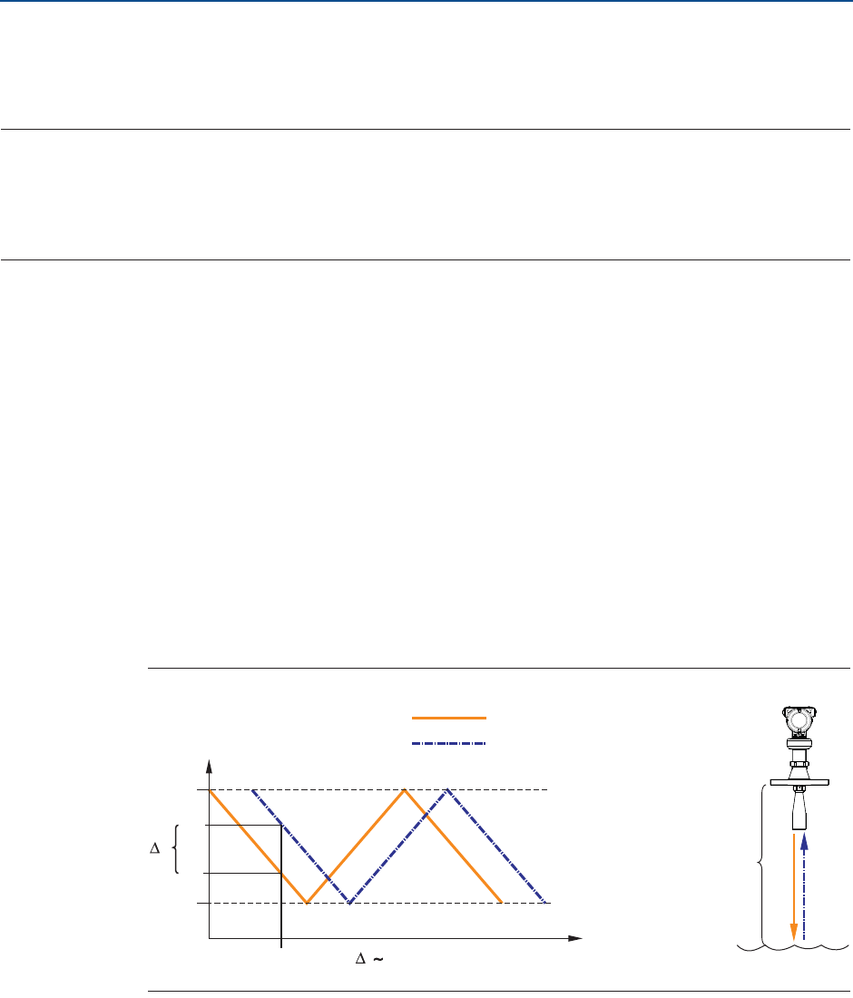
The transmitter continuously emits signal sweeps with a constantly varying frequency
towards the product surface. Since the transmitter continuously changes the frequency of
the transmitted signal, there will be a difference in frequency between the transmitted and
the reflected signals.
The frequency of the reflected signal is subtracted from the frequency of the signal
transmitted at that moment, resulting in a low frequency signal which is proportional to the
distance to the product surface. This signal is further processed to obtain fast, reliable, and
highly accurate level measurements.
Figure 2-1. FMCW-method
d
f0
fmax
fmin
f1
f0
f1
t0
f
f d=Distance
Transmitted signal
Reflected signal
Frequency (GHz)
Time (s)

4
Transmitter Overview
November 2016
Transmitter Overview
Reference Manual
00809-0100-4408, Rev AA
PRELIMINARY
2.2 Process characteristics
2.2.1 Dielectric constant
A key parameter for measurement performance is reflectivity. A high dielectric constant of
the media provides better reflection and enables a longer measuring range.
In addition to the dielectric constant, the measuring range depends on the microwave
frequency, antenna size, and the process conditions (see “Measuring range” on page 121).
2.2.2 Foam and turbulence
Foaming liquids or turbulence may cause weak and varying surface echo amplitudes. The
effects of turbulence are usually minor, but in the most challenging conditions, the
transmitter may be mounted in a still pipe. In addition, measurement performance can be
optimized by enabling the appropriate process conditions parameters, see “Process
conditions” on page 171.
Measurement in foamy applications depends largely on the foam properties. When the
foam is light and airy, the actual product level is measured. For heavy and dense foam, the
transmitter may measure the level of the foam’s upper surface. The Double Surface
Handling function allows the user to select if the foam layer or product surface should be
used as output.
2.2.3 Condensation
Generally, the radar signal is unaffected by condensation and low pressure steam. However,
heavy condensation can effect the measurement. In such applications, air purging may be
required to prevent clogging of the antenna.
In high temperature applications, it is recommended to insulate the tank nozzle. Insulation
prevents the nozzle from becoming a cold spot, and thus reduces the amount of water build
up and condensation on the antenna.
If the temperature in the tank is much higher than the ambient temperature (i.e. tank is
heated and located in a cold area), it might be necessary to heat trace the nozzle in addition
to the insulation.
2.3 Vessel characteristics
2.3.1 In-tank obstructions
The transmitter should be mounted so that objects such as heating coils, ladders, agitators
and so on are not in the radar signal path. These objects may cause false echoes resulting in
reduced measurement performance. However, the transmitter has built-in functions
designed to reduce the influence from disturbing objects where such objects cannot be
totally avoided.
Vertical and inclined structures cause minimal effect since the radar signal is scattered
rather than directed back to the antenna.
5
Transmitter Overview
November 2016
Transmitter Overview
Reference Manual
00809-0100-4408, Rev AA
PRELIMINARY
2.3.2 Tank shape
The shape of the tank bottom affects the measurement signal when the product surface is
close to the tank bottom. The transmitter has built-in functions which optimize
measurement performance for various bottom shapes.
2.4 Application examples
The Rosemount 5408 and 5408:SIS are ideal for level measurements on a broad range of
liquids and slurries. The transmitter is virtually unaffected by changing density,
temperature, pressure, media dielectric, pH, and viscosity. Non-contacting radar level is
ideal for harsh conditions such as corrosive and sticky media, or when internal tank
obstructions are a limiting factor.
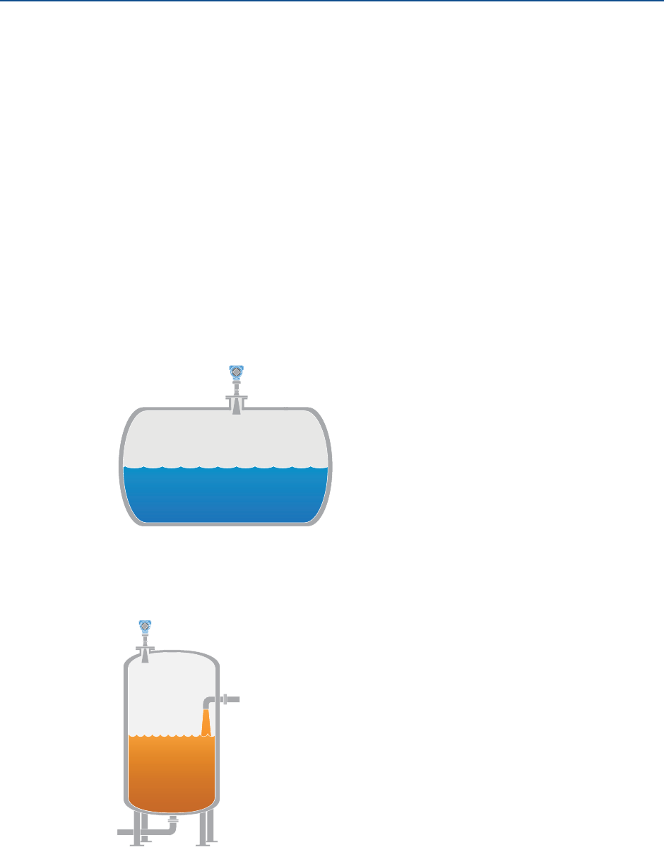
Storage and buffer tanks
The Rosemount 5408 provides accurate and reliable level measurement for storage or
buffer tanks for almost any liquid, e.g. oil, gas condensate, water, chemicals, etc.
Demanding environments
The Rosemount 5408 is a very suitable choice for the most challenging applications, such as
reactors with varying process conditions and product turbulence created by agitators.

6
Transmitter Overview
November 2016
Transmitter Overview
Reference Manual
00809-0100-4408, Rev AA
PRELIMINARY
Reactors and mixing tanks
Rosemount 5408 can help you withstand the rigors of reactor and mixing tanks. Easy to
install and commission, it is also unaffected by virtually any fluid property change.
Still pipe and chamber installations
The Rosemount 5408 is an excellent choice for level measurement in tanks with still pipes. It
may also be used in chambers, but guided wave radar is generally the best fit for these
applications. See “Installation in still pipe/chamber” on page 16 for installation guidelines.
7
Transmitter Overview
November 2016
Transmitter Overview
Reference Manual
00809-0100-4408, Rev AA
PRELIMINARY
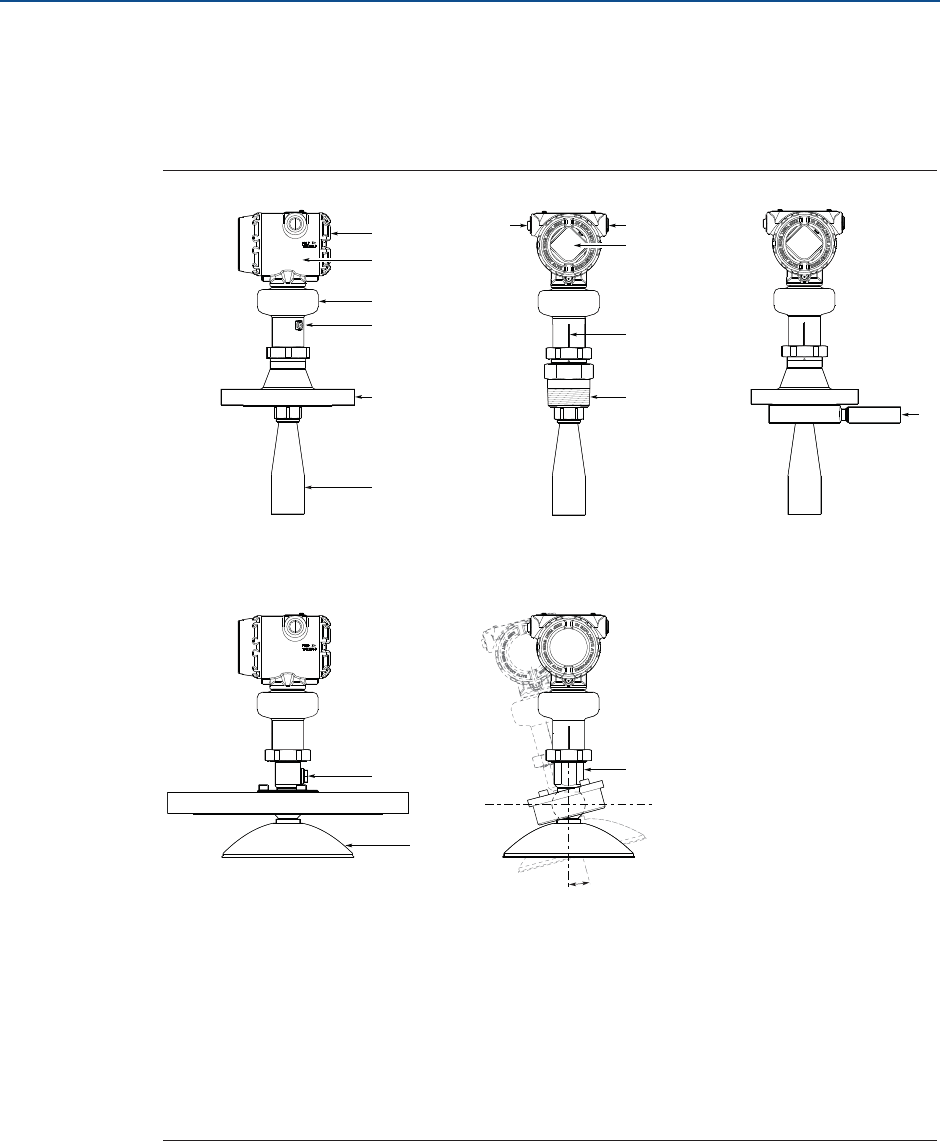
2.5 Components of the transmitter
Figure 2-2 shows the different components of the transmitter. There are different antenna
types and sizes available for various applications.
Figure 2-2. Components
A.
B.
C.
D.
E.
F.
G.
Terminal compartment
Transmitter housing (aluminum or stainless steel)
Sensor module with signal processing electronics
External ground screw
Flanged process connection
Cone antenna
Two cable/conduit entries
(½-14 NPT, M20 x 1.5 or G1/2)
Optional adapters: eurofast® and minifast®
H.
I.
J.
K.
L.
M.
N.
LCD display (optional)
Alignment marker (one per side)
Threaded process connection (NPT or BSPP (G))
Air purge ring (option code PC1 for cone antenna)
Integrated air purge connection
Parabolic antenna
Parabolic antenna with swivel mount
A
B
C
D
E
G
K
G
J
I
F
L
M
H
N
±15°
8
Transmitter Overview
November 2016
Transmitter Overview
Reference Manual
00809-0100-4408, Rev AA
PRELIMINARY
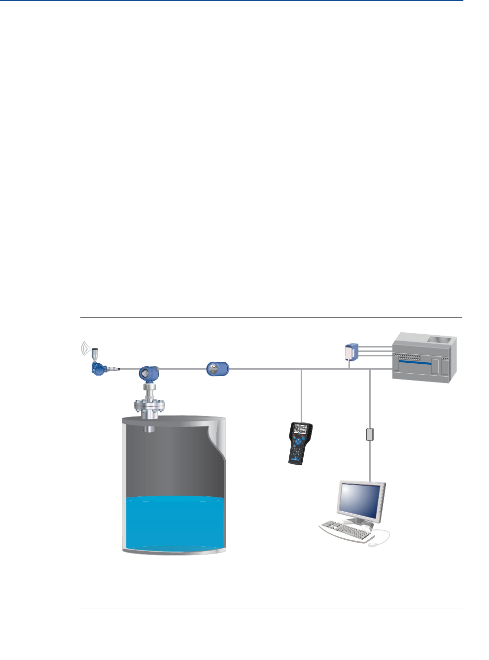
2.6 System integration
The transmitter is loop-powered, and uses the same two wires for power supply and output
signal. The output is a 4-20 mA analog signal superimposed with a digital HART® signal. The
transmitter can be configured for either HART Revision 6 (default) or 7 (option code HR7).
The HART Revision can be switched in field.
By using the optional Rosemount 333 HART Tri-Loop™, the HART signal can be converted up
to three additional 4-20 mA analog signals. With the HART protocol, multidrop
configuration is possible. In this case, communication is restricted to digital, since current is
fixed to the 4 mA minimum value.
The transmitter can be combined with the Emerson™ Wireless 775 THUM™ Adapter to
wirelessly communicate HART data with IEC 62591 (WirelessHART®) technology. In
addition, the transmitter can be connected to a Rosemount 751 Field Signal Indicator, or it
can be equipped with an LCD display.
The transmitter can easily be configured by using a PC with the Rosemount Radar Master
software (running in Instrument Inspector™), a Field Communicator, the AMS™ Suite:
Intelligent Device Manager, or any other Device Descriptor (DD) or Field Device Integration
(FDI) compatible host system.
The Rosemount 5408 and 5408:SIS are compliant to the NAMUR NE 107 Field Diagnostics
for standardized device diagnostic information.
Figure 2-3. System Architecture
A.
B.
C.
D.
Emerson Smart Wireless THUM Adapter
Rosemount 5408
Rosemount 751
475 Field Communicator
E.
F.
G.
H.
Rosemount 333
Host/DCS system
HART modem
Rosemount Radar Master or AMS Device Manager
AB C
D
E
F
G
H
9
Reference Manual
00809-0100-4408, Rev AA
Mechanical Installation
November 2016
Mechanical Installation
PRELIMINARY
Section 3 Mechanical Installation
Safety messages . . . . . . . . . . . . . . . . . . . . . . . . . . . . . . . . . . . . . . . . . . . . . . . . . . . . . . . . . page 9
Review mounting considerations . . . . . . . . . . . . . . . . . . . . . . . . . . . . . . . . . . . . . . . . . . page 10
Review mounting preparations . . . . . . . . . . . . . . . . . . . . . . . . . . . . . . . . . . . . . . . . . . . . page 18
Mount the cone antenna . . . . . . . . . . . . . . . . . . . . . . . . . . . . . . . . . . . . . . . . . . . . . . . . . . page 21
Mount the parabolic antenna . . . . . . . . . . . . . . . . . . . . . . . . . . . . . . . . . . . . . . . . . . . . . . page 36
Adjust display orientation (optional) . . . . . . . . . . . . . . . . . . . . . . . . . . . . . . . . . . . . . . . . page 52
3.1 Safety messages
Procedures and instructions in this section may require special precautions to ensure the
safety of the personnel performing the operation. Information that raises potential safety
issues is indicated by a warning symbol ( ). Refer to the following safety messages before
performing an operation preceded by this symbol.
Failure to follow safe installation and service guidelines could result in death or
serious injury.
Make sure only qualified personnel perform the installation.
Process leaks could result in death or serious injury.
Make sure that the transmitter is handled carefully. If the process seal is damaged,
gas might escape from the tank.
Explosions could result in death or serious injury.
Verify that the operating environment of the transmitter is consistent with the
appropriate hazardous locations certifications.
10
Reference Manual
00809-0100-4408, Rev AA
Mechanical Installation
November 2016
Mechanical Installation
PRELIMINARY
3.2 Review mounting considerations
Before installing the transmitter, consider recommendations for mounting position,
sufficient free space, nozzle requirements, etc.
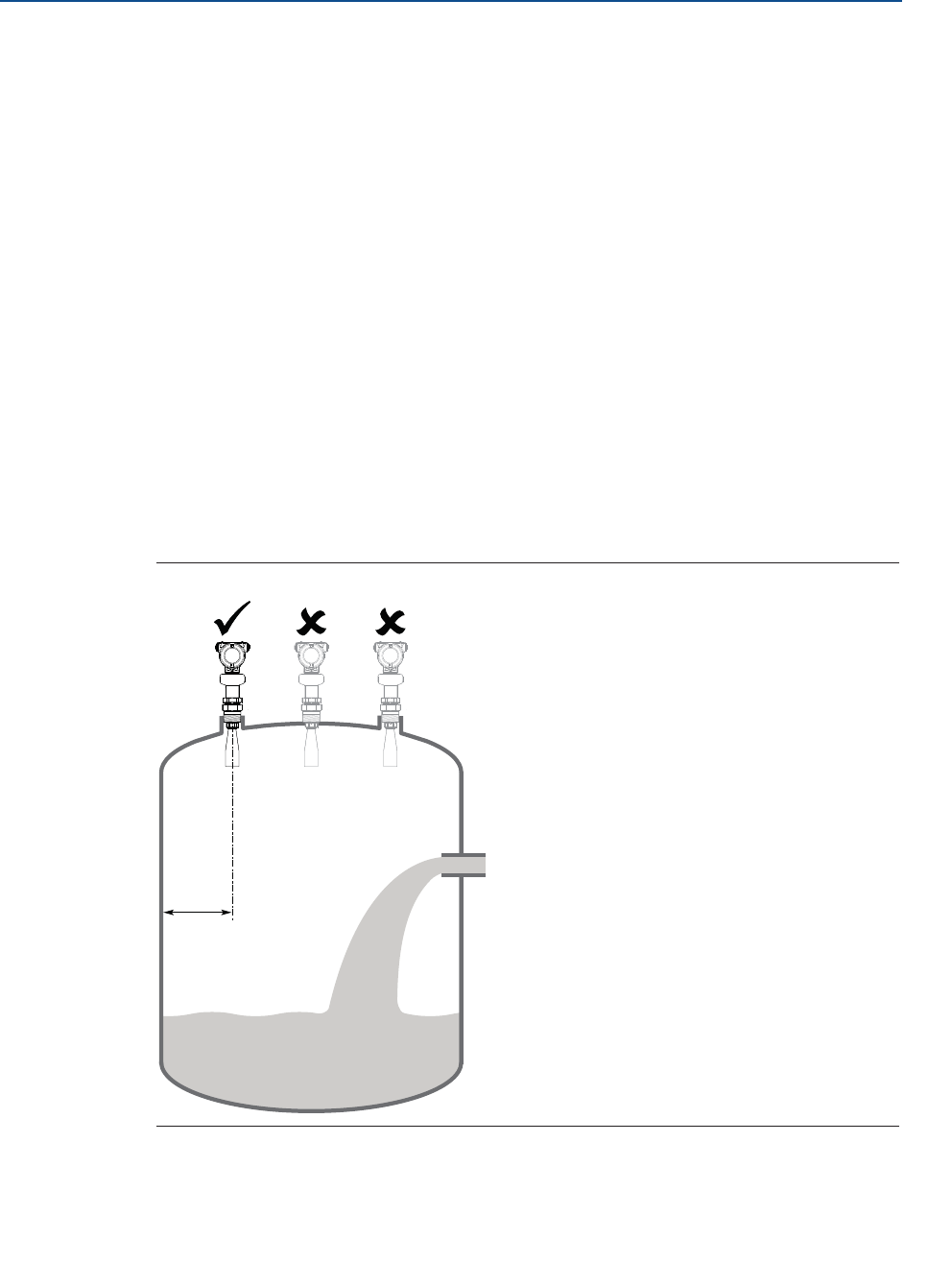
3.2.1 Mounting position
When finding an appropriate location on the tank for the transmitter, the conditions of the
tank must be carefully considered.
Consider the following guidelines when mounting the transmitter:
For optimal performance, the transmitter should be installed in locations with a
clear and unobstructed view of the product surface.
Keep a distance of at least 8 in. (200 mm) distance to the tank wall.
The optimal location is usually 1/4 of the tank diameter.
Do not install the transmitter in the center of the tank.
Do not mount close to or above the inlet stream.
Multiple Rosemount™ 5408 and 5408:SIS Level Transmitters can be used in the
same tank without interfering with each other.
Figure 3-1. Mounting Position
> 8 in.
(200 mm)
11
Reference Manual
00809-0100-4408, Rev AA
Mechanical Installation
November 2016
Mechanical Installation
PRELIMINARY
3.2.2 Antenna size
Choose as large antenna diameter as possible. A larger receiving area concentrates the radar
beam and ensures maximum antenna gain. Increased antenna gain permits greater margin
for weak surface echoes.
In addition, a larger antenna results in a smaller beam angle and thereby, less interference
from any internal structures in the tank.
3.2.3 Inclination of antenna
Ensure the antenna is aligned vertically to the product surface for best measuring
performance. The parabolic antenna comes with swivel connection that adjusts for angled
tank roofs.
Figure 3-2. Inclination
3.2.4 Non-metallic tanks
The walls in non-metallic tanks can be invisible to the radar signal, so nearby objects outside
the tank may cause disturbing radar echoes. Wherever possible, the transmitter should be
positioned so that objects close to the tank are kept outside the signal beam.
Max. 3° Max. 1.5°
Cone antenna Parabolic antenna
12
Reference Manual
00809-0100-4408, Rev AA
Mechanical Installation
November 2016
Mechanical Installation
PRELIMINARY
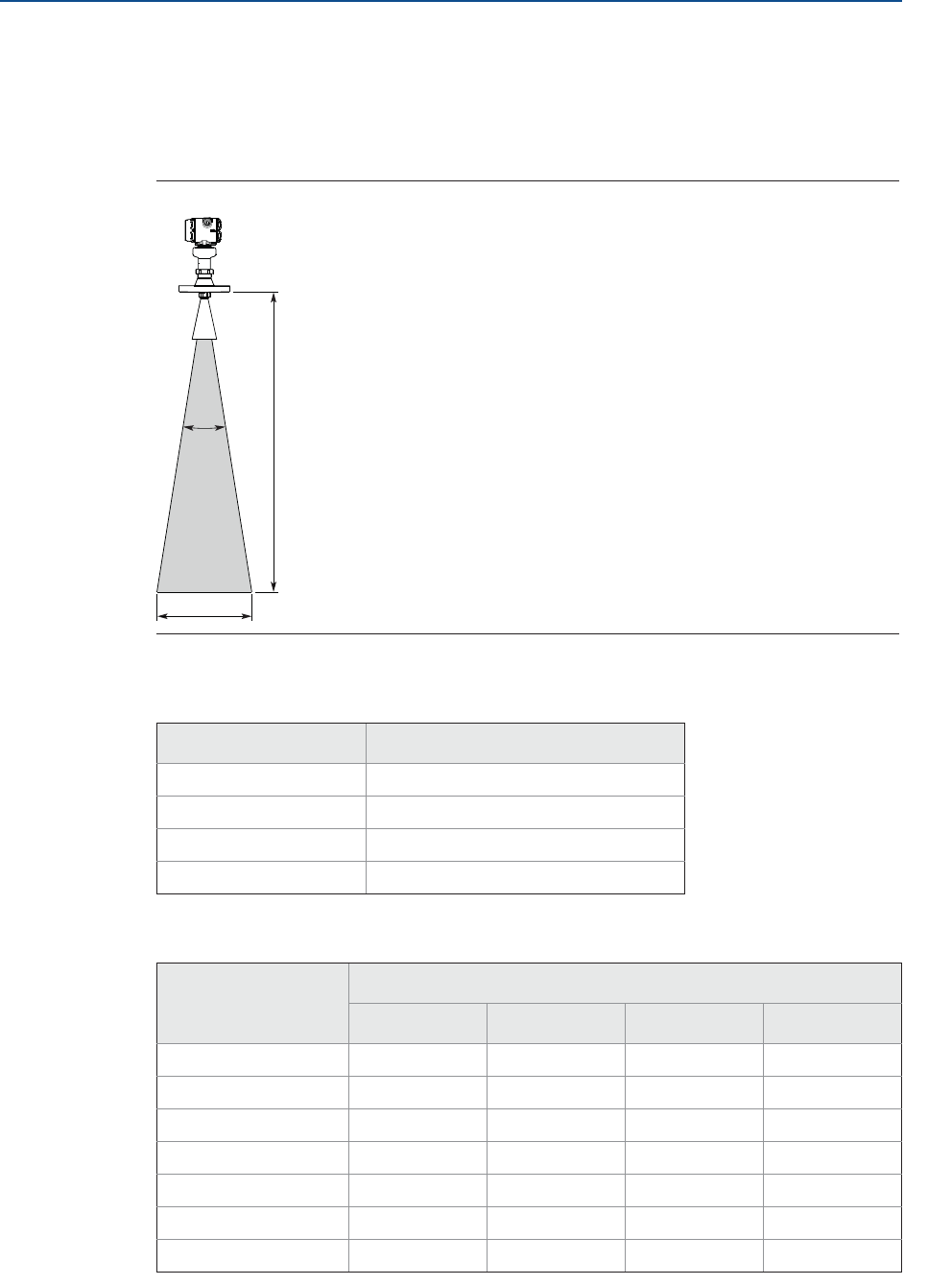
3.2.5 Beam width and beam angle
The transmitter should be mounted with as few internal structures as possible within the
signal beam. Refer to Table 3-1 for beam angle and Table 3-2 for beam width at different
distances.
Figure 3-3. Beam Angle and Beam Width
Table 3-1. Beam Angle
Table 3-2. Beam Width
Antenna size Beam angle (Į)
2-in. cone 18°
3-in. cone 14°
4-in. cone 10°
Parabolic 4.5°
Distance (D), ft (m) Beam width (W), ft (m)
2-in. cone 3-in. cone 4-in. cone Parabolic
16 (5) 5.2 (1.6) 4.0 (1.2) 2.9 (0.9) 1.3 (0.4)
33 (10) 10.4 (3.2) 8.1 (2.5) 5.7 (1.8) 2.6 (0.8)
49 (15) 15.6 (4.8) 12.1 (3.7) 8.6 (2.6) 3.9 (1.2)
66 (20) 20.8 (6.3) 16.1 (4.9) 11.5 (3.5) 5.2 (1.6)
82 (25) 26.0 (7.9) 20.1 (6.1) 14.3 (4.4) 6.4 (2.0)
98 (30) 31.2 (9.5) 24.2 (7.4) 17.2 (5.3) 7.7 (2.4)
131 (40) 41.6 (12.7) 32.2 (9.8) 23.0 (7.0) 10.3 (3.1)
D
D
W
13
Reference Manual
00809-0100-4408, Rev AA
Mechanical Installation
November 2016
Mechanical Installation
PRELIMINARY
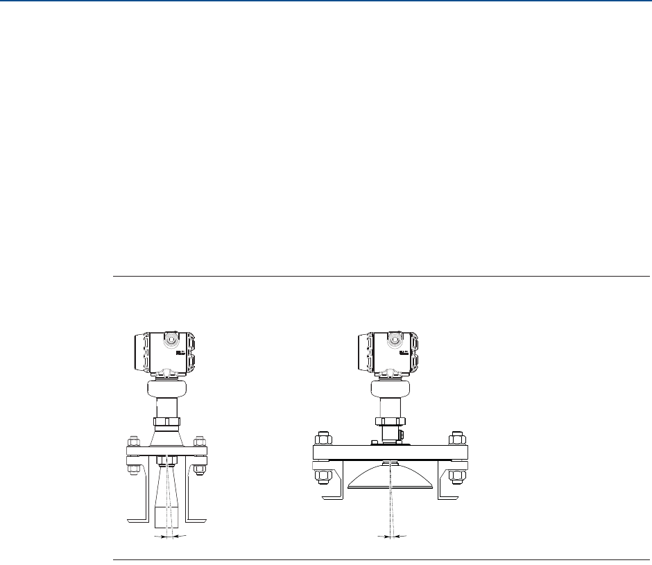
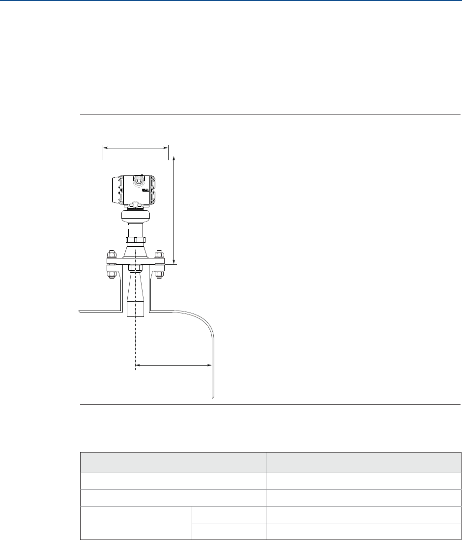
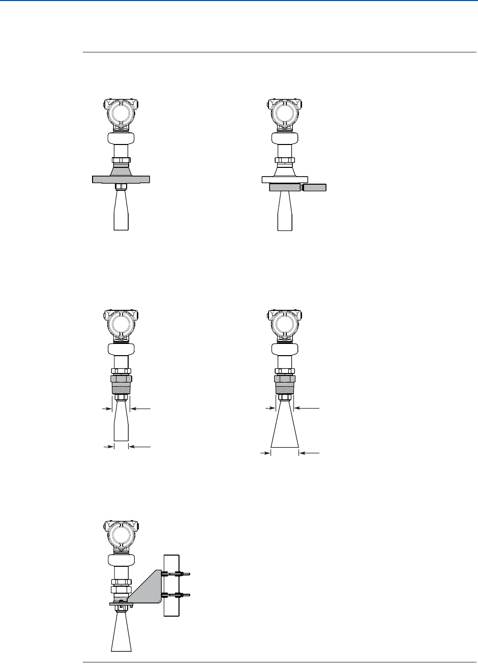
3.2.6 Nozzle requirements
In order to allow the microwaves to propagate undisturbed, the nozzle dimensions should
be kept within the specified limits as given in Table 3-3 and Table 3-4.
Cone antenna
For best performance, the cone antenna should extend at least 0.4 in. (10 mm) below the
nozzle. If required, use the extended cone antenna versions (option code S1 or S2).
However, the antenna can be recessed in smooth nozzles up to 4 ft (1.2 m). Note that if the
inside of the nozzle has irregularities (e.g. due to bad welding, rust or deposit), then use the
extend cone antenna.
Figure 3-4. Mounting of the Cone Antenna
Table 3-3. Nozzle Requirements for Cone Antenna, in Inches (Millimeters)
Antenna size Minimum nozzle
diameter (D)(1)
1. The antennas are sized to fit within schedule 80 or lower pipes.
Maximum nozzle height (H)(2)(3)
2. The values are valid for cone antennas without antenna extension.
3. The cone antenna can be recessed in smooth nozzles up to 4 ft (1.2 m), but note that the accuracy may be reduced in the
region close to the nozzle. If this is not acceptable, use the extended cone antenna versions (option code S1 or S2).
SST cone SST cone with air purge
ring (code PC1)
2-in. (DN50) 1.94 (49.3)
3-in. (DN80) 2.80 (71.0)
4-in. (DN100) 3.78 (96.0)
D
H
> 0.4 in. (10 mm)
14
Reference Manual
00809-0100-4408, Rev AA
Mechanical Installation
November 2016
Mechanical Installation
PRELIMINARY
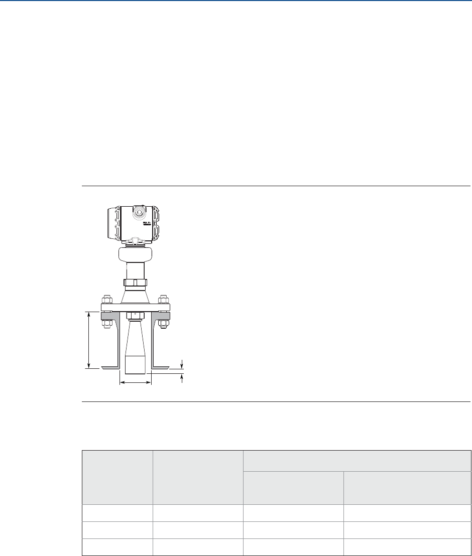
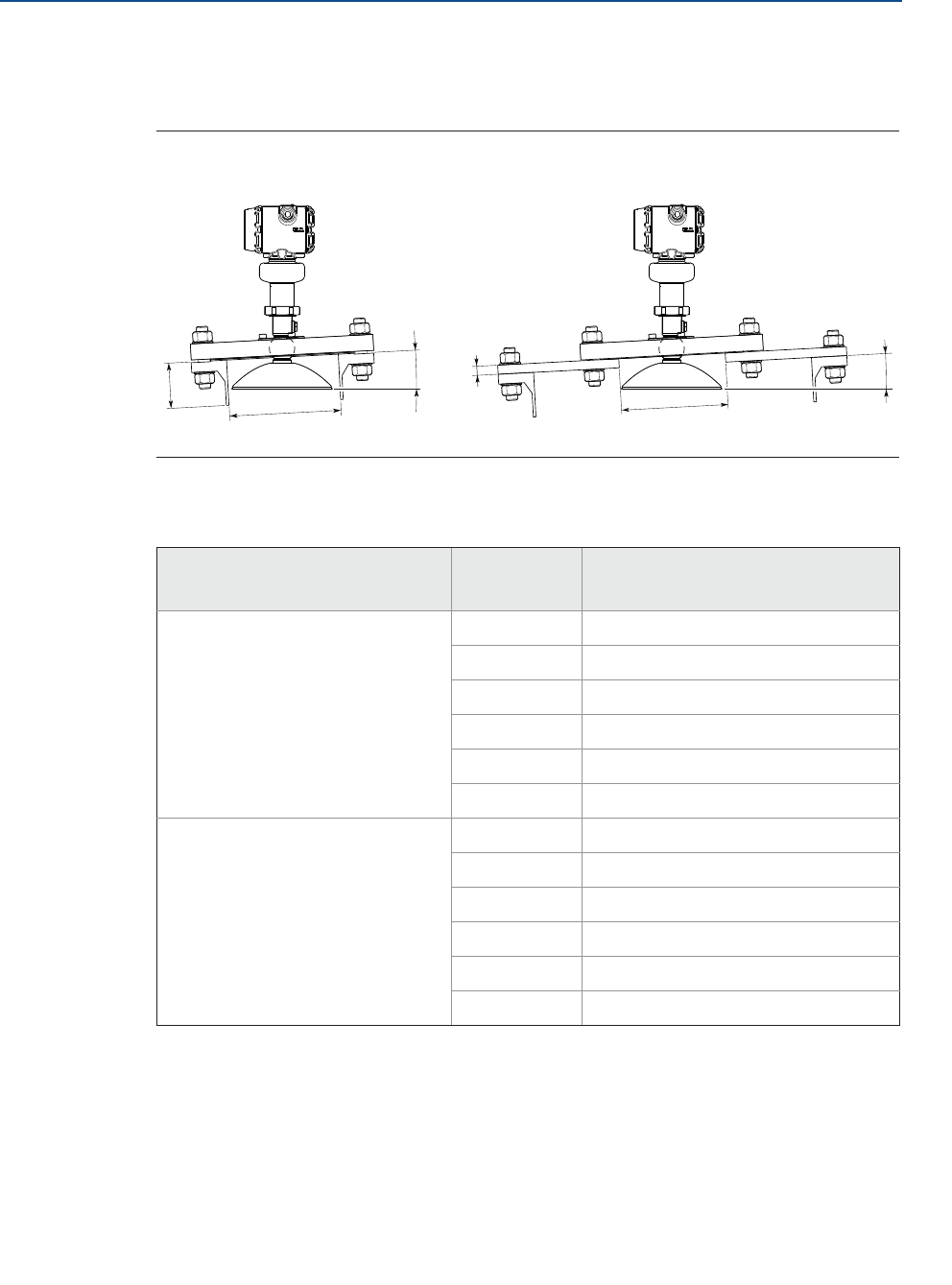
Parabolic antenna
See Table 3-4 for nozzle height recommendations at different inclination angle.
Figure 3-5. Mounting of the Parabolic Antenna
Table 3-4. Nozzle Requirements for Parabolic Antenna
Nozzle size (D) Inclination
angle (Į)
Maximum nozzle height (H),
in. (mm)(1)
1. Note that the inside of the nozzle must be smooth (i.e. avoid bad welding, rust or deposit).
Pipe schedule std, Ø 8 in. (200 mm) 0° 5.9 (150)
3° 5.5 (140)
6° 1.6 (40)
9° 1.2 (30)
12° 1.0 (25)
15° 0.6 (15)
Pipe schedule std, Ø10 in. (250 mm) 0° 8.0 (200)
3° 8.0 (200)
6° 8.0 (200)
9° 8.0 (200)
12° 5.9 (150)
15° 4.3 (110)
ĮH
Ø 8 in. (200 mm)
D
Nozzle mounting Flange mounting in manhole cover
Į
H
15
Reference Manual
00809-0100-4408, Rev AA
Mechanical Installation
November 2016
Mechanical Installation
PRELIMINARY
3.2.7 Free space requirements
If the transmitter is mounted close to a wall or other tank obstructions such as heating coils
and ladders, noise might appear in the measurement signal. Therefore the following
minimum clearance, according to Table 3-5, must be maintained.
For easy access to the transmitter, mount it with sufficient service space (see Table 3-5).
Figure 3-6. Free Space Requirements
Table 3-5. Free Space Requirements
Free space requirements Distance, in. (mm)
Service space width (A) 20 (500)
Service space height (B) 24 (600)
Distance to tank wall (L) Minimum 8 (200)
Recommended 1/4 of the tank diameter
L
B
A
16
Reference Manual
00809-0100-4408, Rev AA
Mechanical Installation
November 2016
Mechanical Installation
PRELIMINARY
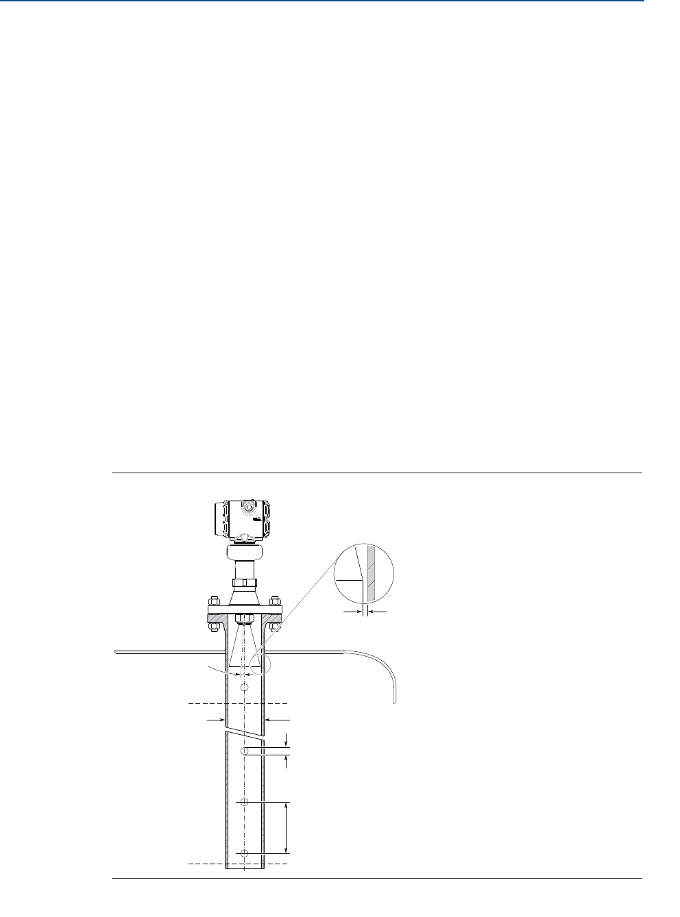
3.2.8 Installation in still pipe/chamber
Installation in still pipe/chamber is recommended for tanks where surface conditions may
be extremely turbulent. By using a pipe, foam or turbulence is reduced. All cone antenna
sizes can be used for still pipe/chamber installations. Consider the following still pipe
requirements:
Pipe
Pipes should be an all-metal material.
Pipe should have a constant inside diameter.
The inner surface must be smooth and clear of any rough edges.
(Smooth pipe joints are acceptable, but may reduce accuracy.)
The end of the pipe must extend beyond the zero level.
Holes(1)
Minimum hole diameter is 0.25 in. (6 mm).
Maximum hole diameter should not exceed 10% of the pipe diameter (D).
Minimum distance between holes is 6 in. (150 mm).
Holes should be drilled on one side only and deburred.
Drill one hole above maximum product surface.
Antenna
The gap between cone antenna and still pipe is limited to 0.2 in. (5 mm). If
required, order an oversized antenna and cut on location.
Figure 3-7. Still Pipe Requirements
1. For guidelines on slotted pipes, consult your local Emerson Automation Solutions representative.
Min. 0.25 in. (6 mm)
Max. D/10
Max. 0.2 in.
(5 mm)
Pipe diameter (D)
Min. 6 in. (150 mm)
Max. 1°
Level = 100%
Level = 0%
17
Reference Manual
00809-0100-4408, Rev AA
Mechanical Installation
November 2016
Mechanical Installation
PRELIMINARY
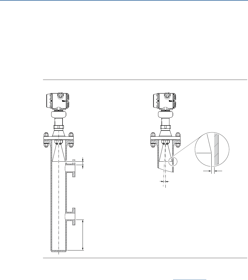
Consider the following chamber requirements:
Pipes should be an all-metal material.
Pipe should have a constant inside diameter.
Inlet pipes should not protrude into the inside of the stand pipe.
The inner surface must be smooth and clear of any rough edges.
(Smooth pipe joints are acceptable, but may reduce accuracy.)
The gap between cone antenna and stand pipe is limited to 0.2 in. (5 mm). If
required, order an oversized antenna and cut on location.
Figure 3-8. Chamber Requirements
For more information and installation requirements, refer to the Guidelines for Choosing
and Installing Radar in Stilling Wells and Bypass Chambers Technical Note.
3.2.9 Ball valve installation
The transmitter can be isolated from the process by using a valve:
Use a full-port ball valve.
Ensure there is no edge between the ball valve and the nozzle or still pipe, the
inside should be smooth.
Valves can be combined with still pipe.
Max. 0.2 in.
(5 mm)
Min. 6 in. (150 mm)
Max. 1°
Min. 0.4 in. (10 mm)
18
Reference Manual
00809-0100-4408, Rev AA
Mechanical Installation
November 2016
Mechanical Installation
PRELIMINARY
3.3 Review mounting preparations
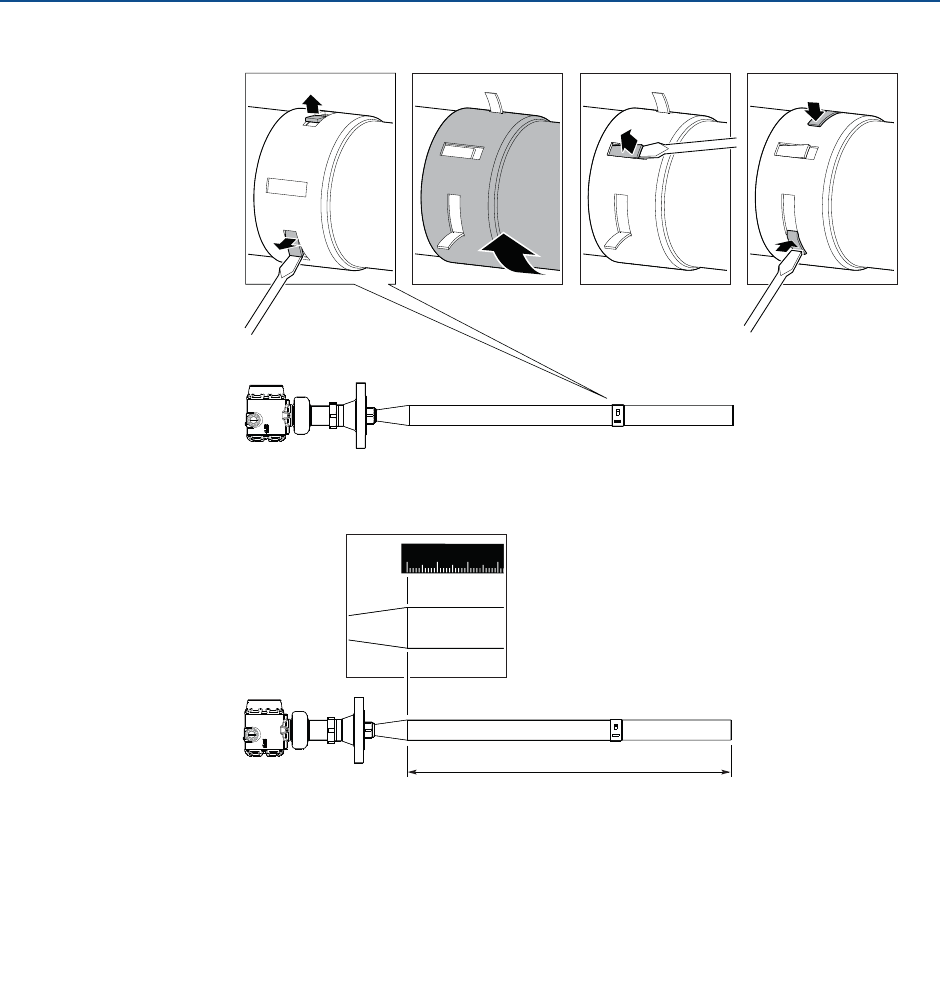
3.3.1 Assemble the segmented cone antenna
This section applies to the segmented cone antenna (option code S2). Use only one
segment; the total antenna length should not exceed 47.2 in. (1200 mm).
To determine the antenna length, follow the guidelines in section “Nozzle requirements” on
page 13.
1. Insert the segment into the cone antenna until it bottoms.
2. Mark where to cut the segment.
3. Cut the extension at the marking.
4. Remove any burrs.
5. Insert the segment into the cone antenna until it bottoms.
12345678
09
19
Reference Manual
00809-0100-4408, Rev AA
Mechanical Installation
November 2016
Mechanical Installation
PRELIMINARY
6. Secure the segment to the antenna.
7. Measure the Antenna Extension Length (L).
8. Update the transmitter configuration to the new Antenna Extension Length (L).
Rosemount Radar Master: AMS Device Manager and
Field Communicator:
Under Configure, select Level Setup >
Antenna.
From the Home screen, select
Configure > Manual Setup > Level
Setup > Antenna.
123 4
L
123
0
20
Reference Manual
00809-0100-4408, Rev AA
Mechanical Installation
November 2016
Mechanical Installation
PRELIMINARY
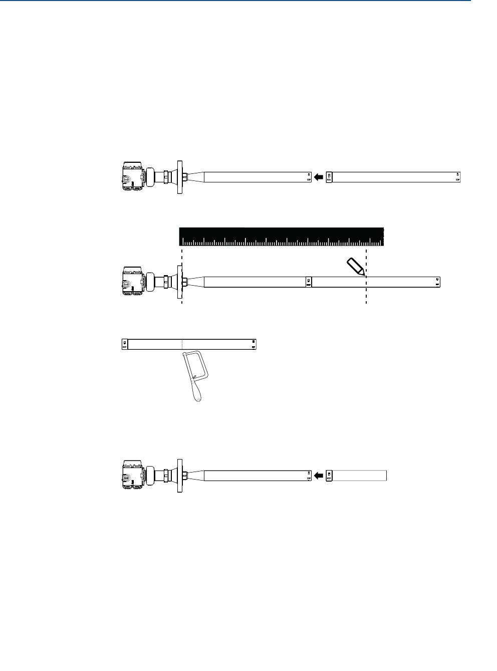
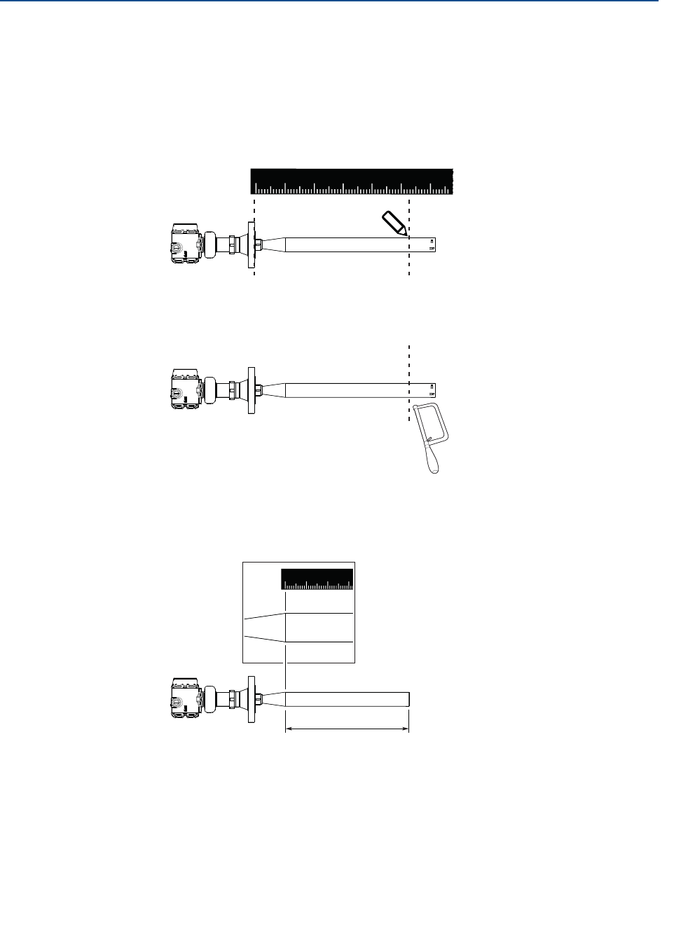
3.3.2 Shorten the extended cone antenna
This section only applies to the extended cone antenna (option code S1).
To determine the antenna length, follow the guidelines in section “Nozzle requirements” on
page 13.
1. Mark where to cut the antenna.
2. Cut the antenna at the marking.
3. Remove any burrs.
4. Measure the Antenna Extension Length (L).
5. Update the transmitter configuration to the new Antenna Extension Length (L).
Rosemount Radar Master: AMS Device Manager and
Field Communicator:
Under Configure, select Level Setup >
Antenna.
From the Home screen, select
Configure > Manual Setup > Level
Setup > Antenna.
123456
0
L
123
0
21
Reference Manual
00809-0100-4408, Rev AA
Mechanical Installation
November 2016
Mechanical Installation
PRELIMINARY
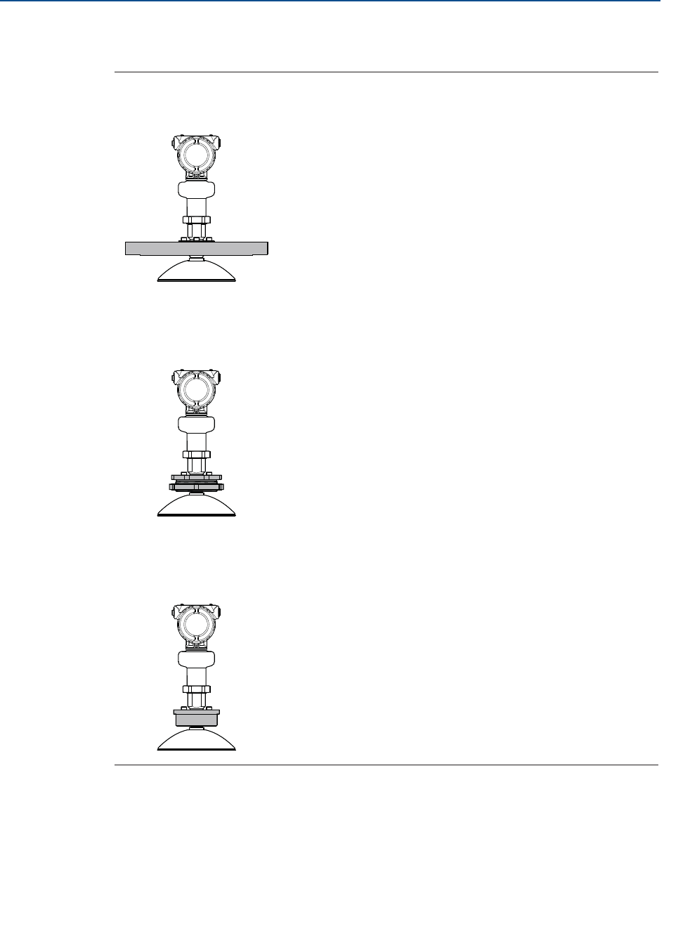
3.4 Mount the cone antenna
Figure 3-9. Overview
d
D
d
D
Flanged version
(see page 22)
Flanged version with air purge ring
(see page 23)
Threaded version, D < d
(see page 25)
Threaded version, D > d
(see page 28)
Bracket mounting
(see page 31)
22
Reference Manual
00809-0100-4408, Rev AA
Mechanical Installation
November 2016
Mechanical Installation
PRELIMINARY
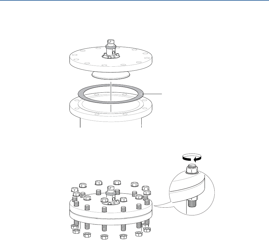
3.4.1 Flanged version
1. Lower transmitter with antenna and flange into the nozzle.
2. Tighten bolts and nuts with sufficient torque for the flange and gasket choice.
3. Align the transmitter head (see page 34).
Gasket
23
Reference Manual
00809-0100-4408, Rev AA
Mechanical Installation
November 2016
Mechanical Installation
PRELIMINARY
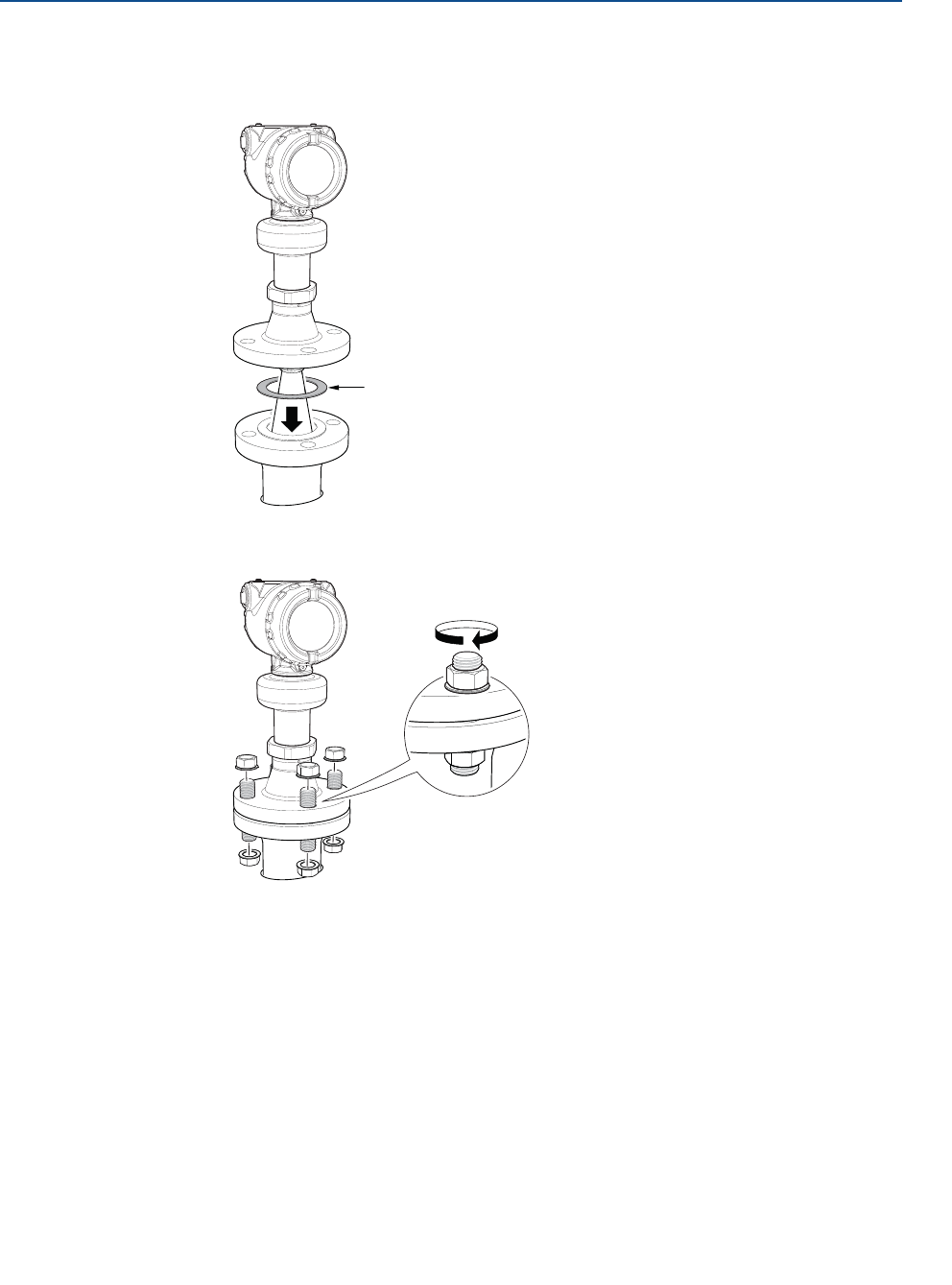
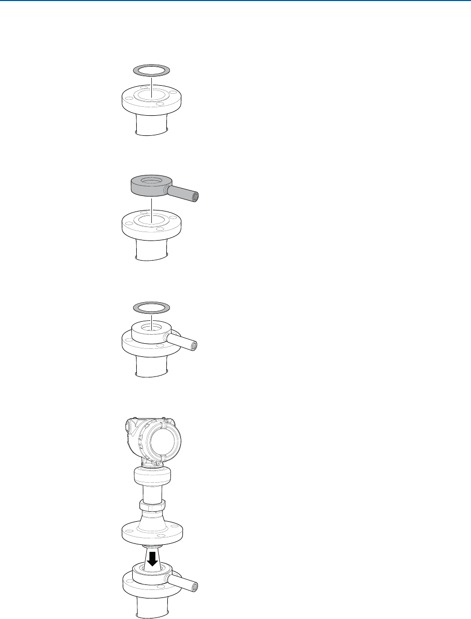
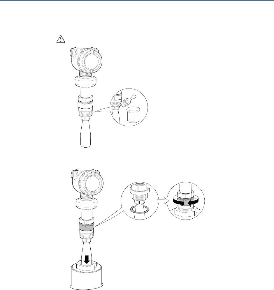
3.4.2 Flanged version with air purge ring
1. Place a suitable gasket on the tank flange.
2. Place the purge ring over the gasket.
3. Place a suitable gasket over the purge ring.
4. Lower transmitter with antenna and flange into the nozzle.
24
Reference Manual
00809-0100-4408, Rev AA
Mechanical Installation
November 2016
Mechanical Installation
PRELIMINARY
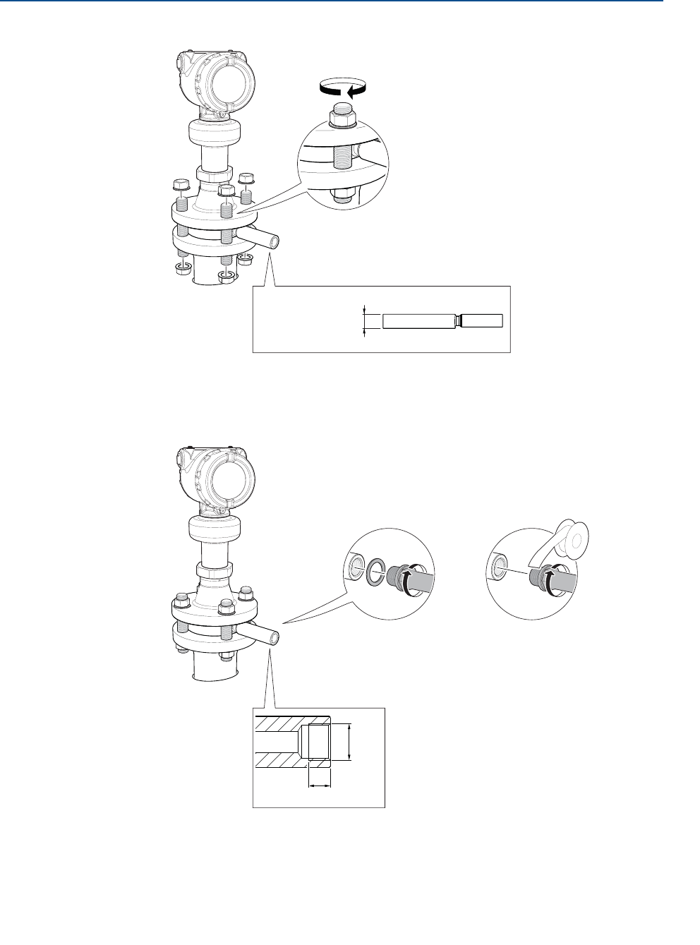
5. Tighten bolts and nuts with sufficient torque for the flange and gasket choice.
6. Connect the air purging system.
Use thread sealant or suitable gasket according to your site procedures.
7. Align the transmitter head (see page 34).
1.0 in. (25.5 mm)
G3/8"
0.4 in. (10 mm)
or
25
Reference Manual
00809-0100-4408, Rev AA
Mechanical Installation
November 2016
Mechanical Installation
PRELIMINARY
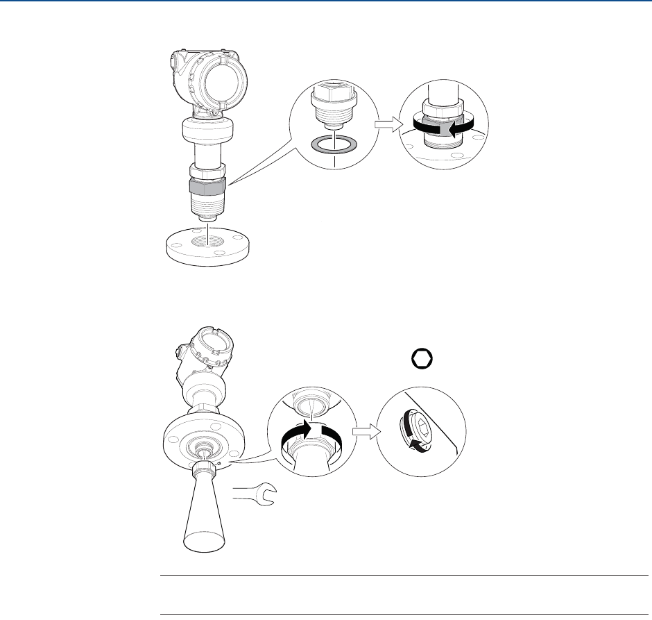
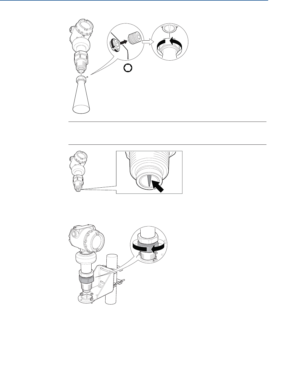
3.4.3 Threaded version
Antenna diameter (D) < Thread diameter (d)
Flanged tank connection
1. Place a suitable gasket on the tank flange.
2. Place the customer supplied flange over the gasket.
3. Tighten the bolts and nuts with sufficient torque for the flange and gasket choice.
4. Apply anti-seize paste or PTFE tape on threads according to your site procedures.
Gasket may be used as a sealant for adapters with 1½ or 2-in. BSPP (G) threads.
26
Reference Manual
00809-0100-4408, Rev AA
Mechanical Installation
November 2016
Mechanical Installation
PRELIMINARY
5. Lower transmitter with antenna and flange into the nozzle.
6. Align the transmitter head (see page 34).
Gasket
(for 1½-in. and 2-in. BSPP
(G) threads only)
27
Reference Manual
00809-0100-4408, Rev AA
Mechanical Installation
November 2016
Mechanical Installation
PRELIMINARY
Threaded tank connection
1. Apply anti-seize paste or PTFE tape on threads according to your site procedures.
Gasket may be used as a sealant for adapters with 1½ or 2-in. BSPP (G) threads.
2. Mount the transmitter on tank.
3. Align the transmitter head (see page 34).
Gasket
(for 1½-in. and 2-in. BSPP
(G) threads only)

28
Reference Manual
00809-0100-4408, Rev AA
Mechanical Installation
November 2016
Mechanical Installation
PRELIMINARY
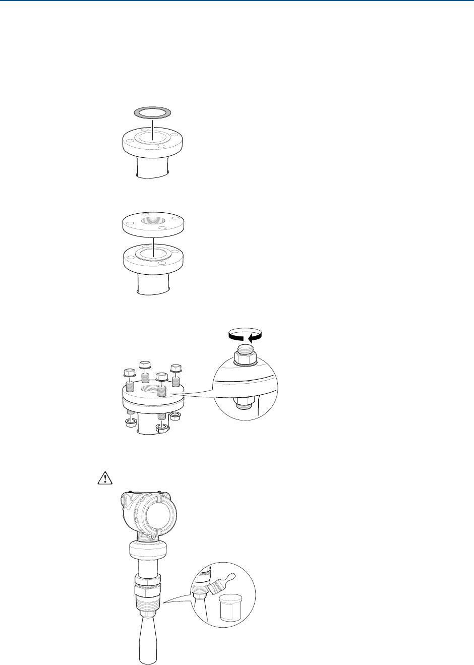
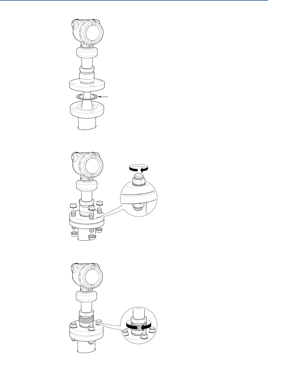
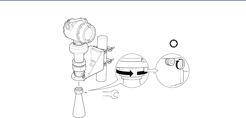
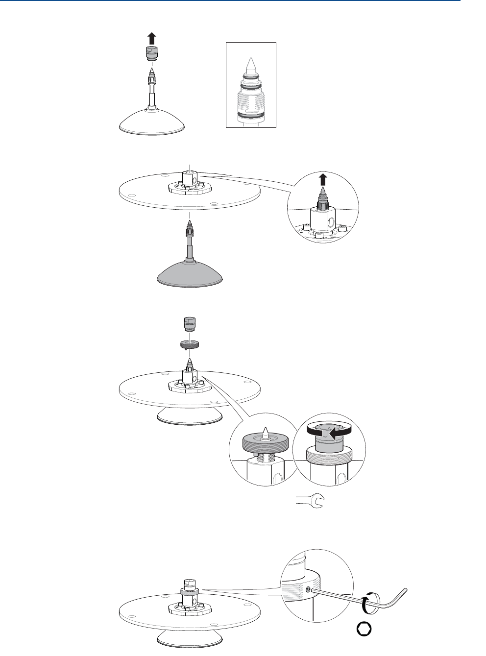
Antenna diameter (D) > Thread diameter (d)
1. Unscrew and remove the antenna.
2. Apply anti-seize paste or PTFE tape on threads according to your site procedures.
Gasket may be used as a sealant for adapters with 1½ or 2-in. BSPP (G) threads.
Note
Do not scratch the microwave launcher. The microwave launcher is sensitive to
mechanical impacts.
H2 mm
Microwave launcher
29
Reference Manual
00809-0100-4408, Rev AA
Mechanical Installation
November 2016
Mechanical Installation
PRELIMINARY
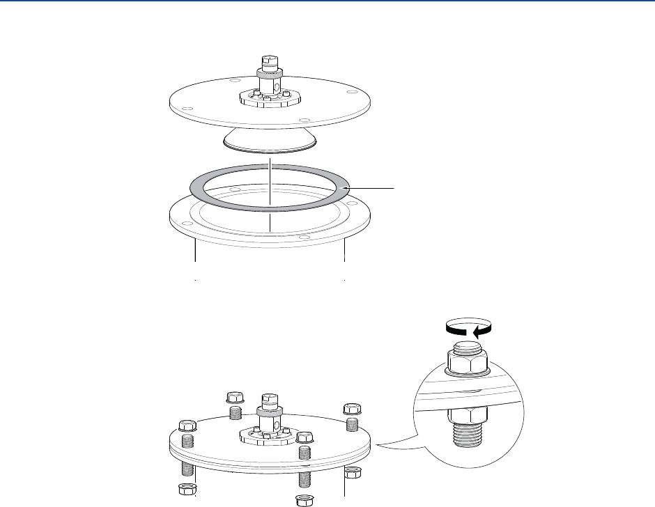
3. Mount the adapter on the customer supplied flange.
4. Mount the antenna.
Gasket
(for 1½-in. and 2-in. BSPP
(G) threads only)
Note
Visually inspect the microwave launcher for damage and dirt. See page 28.
Torque 20 in-lb (2 Nm)
H2 mm
Torque 250 in-lb (28 Nm)
38 mm
30
Reference Manual
00809-0100-4408, Rev AA
Mechanical Installation
November 2016
Mechanical Installation
PRELIMINARY
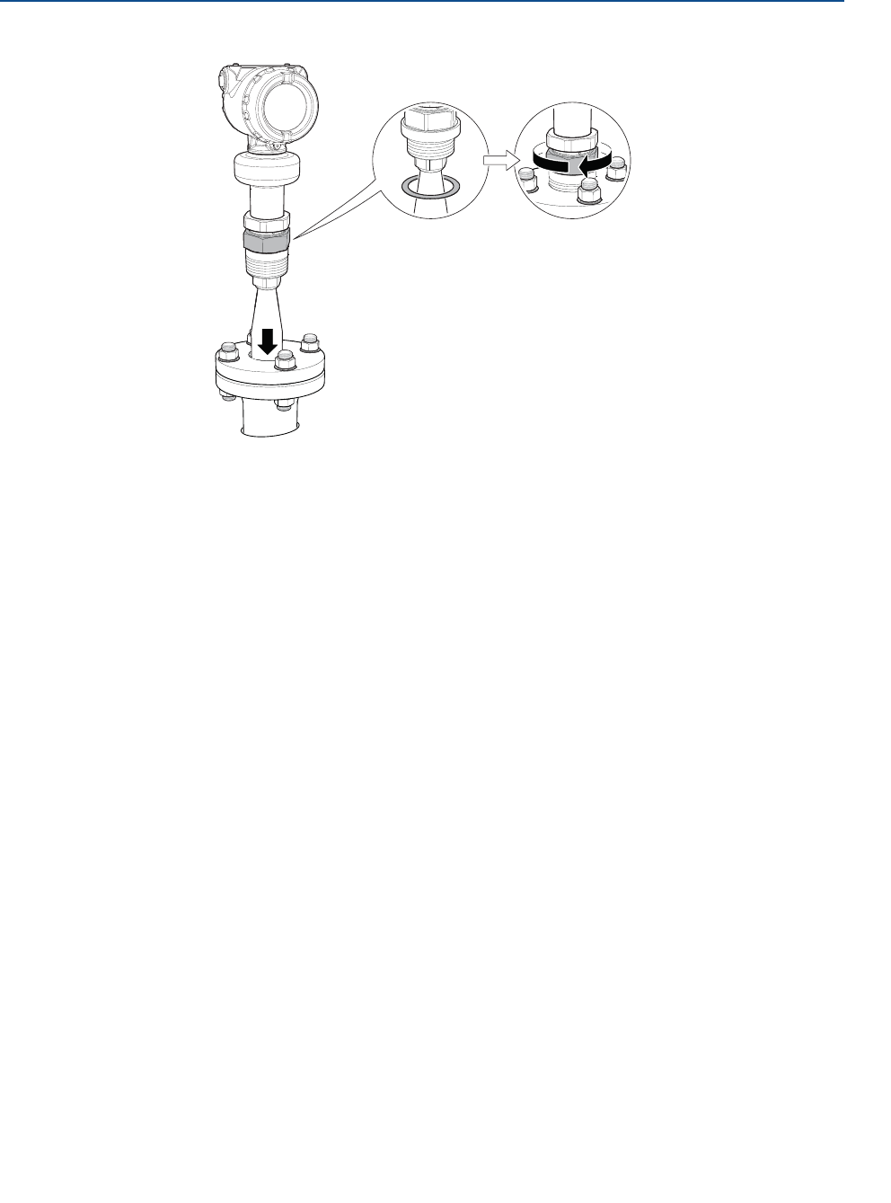
5. Lower transmitter with antenna and flange into the nozzle.
6. Tighten the bolts and nuts with sufficient torque for the flange and gasket choice.
7. Screw the adapter until it is properly tightened.
8. Align the transmitter head (see page 34).
Gasket
31
Reference Manual
00809-0100-4408, Rev AA
Mechanical Installation
November 2016
Mechanical Installation
PRELIMINARY
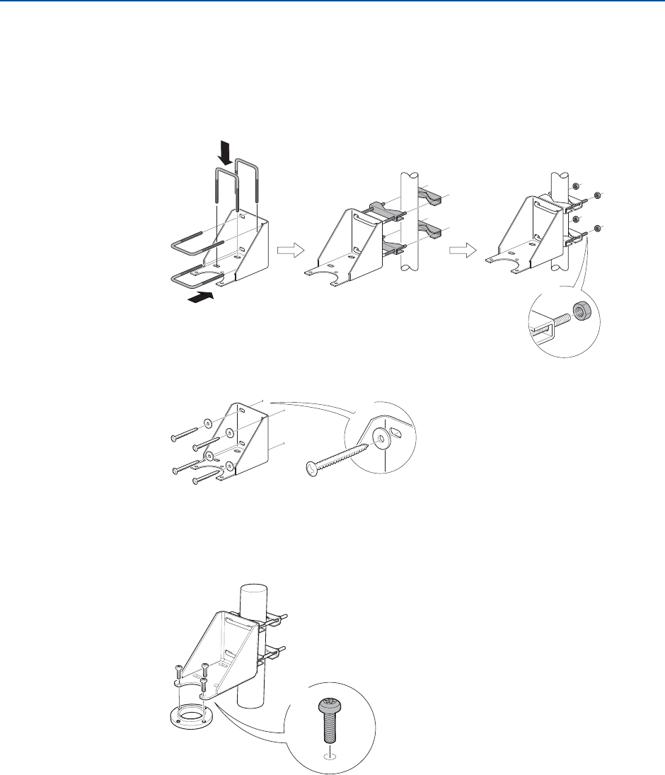
3.4.4 Bracket mounting
1. Mount the bracket to the pipe/wall.
On pipe:
On wall:
2. Mount the holder to the bracket.
4X
Vertical pipe
Horizontal pipe
4X
Use screws suitable
for the purpose
3X
32
Reference Manual
00809-0100-4408, Rev AA
Mechanical Installation
November 2016
Mechanical Installation
PRELIMINARY
3. Unscrew and remove the antenna.
4. Screw the transmitter into the holder.
Note
Do not scratch the microwave launcher. The microwave launcher is sensitive to
mechanical impacts.
H2 mm
Microwave launcher
33
Reference Manual
00809-0100-4408, Rev AA
Mechanical Installation
November 2016
Mechanical Installation
PRELIMINARY
5. Mount the antenna.
6. Align the transmitter head (see page 34).
Torque 20 in-lb (2 Nm)
H2 mm
Torque 250 in-lb (28 Nm)
38 mm
34
Reference Manual
00809-0100-4408, Rev AA
Mechanical Installation
November 2016
Mechanical Installation
PRELIMINARY
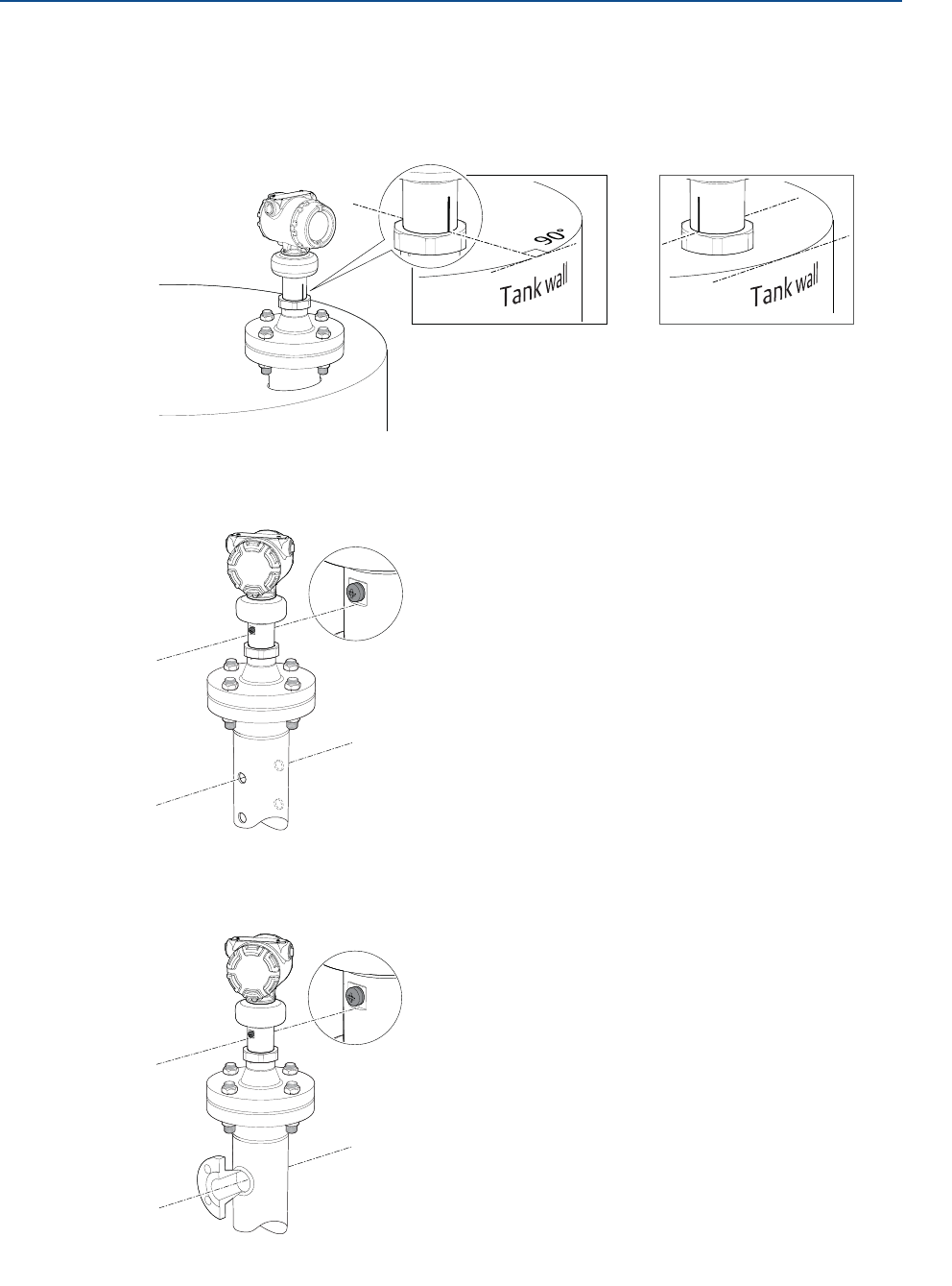
3.4.5 Align transmitter head
Open tank
Align the marking on sensor module either toward or along the tank wall.
Still pipe
Align the external ground screw toward the holes of the still pipe.
Chamber
Align the external ground screw toward the process connections.
or
35
Reference Manual
00809-0100-4408, Rev AA
Mechanical Installation
November 2016
Mechanical Installation
PRELIMINARY
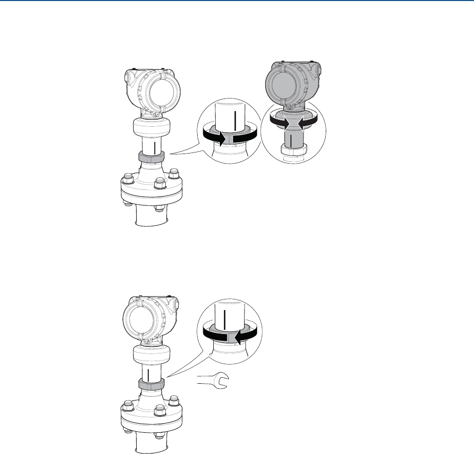
Procedure
1. Loosen the nut slightly and turn the transmitter.
2. Verify the transmitter head is properly aligned (see page 52 for direction).
3. Tighten the nut.
Torque 355 in-lb (40 Nm)
60 mm
36
Reference Manual
00809-0100-4408, Rev AA
Mechanical Installation
November 2016
Mechanical Installation
PRELIMINARY
3.5 Mount the parabolic antenna
Figure 3-10. Overview
Flanged version
(see page 37)
Threaded version
(see page 38)
Welded version
(see page 42)
37
Reference Manual
00809-0100-4408, Rev AA
Mechanical Installation
November 2016
Mechanical Installation
PRELIMINARY
3.5.1 Flanged version
1. Lower the flange and antenna assembly into the nozzle.
2. Tighten the bolts and nuts with sufficient torque for the flange and gasket choice.
3. Adjust the inclination of the antenna (see page 48).
4. Connect the air purging system (see page 51).
Gasket
38
Reference Manual
00809-0100-4408, Rev AA
Mechanical Installation
November 2016
Mechanical Installation
PRELIMINARY
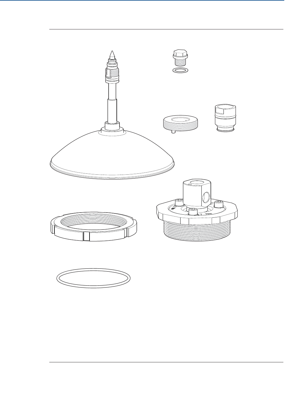
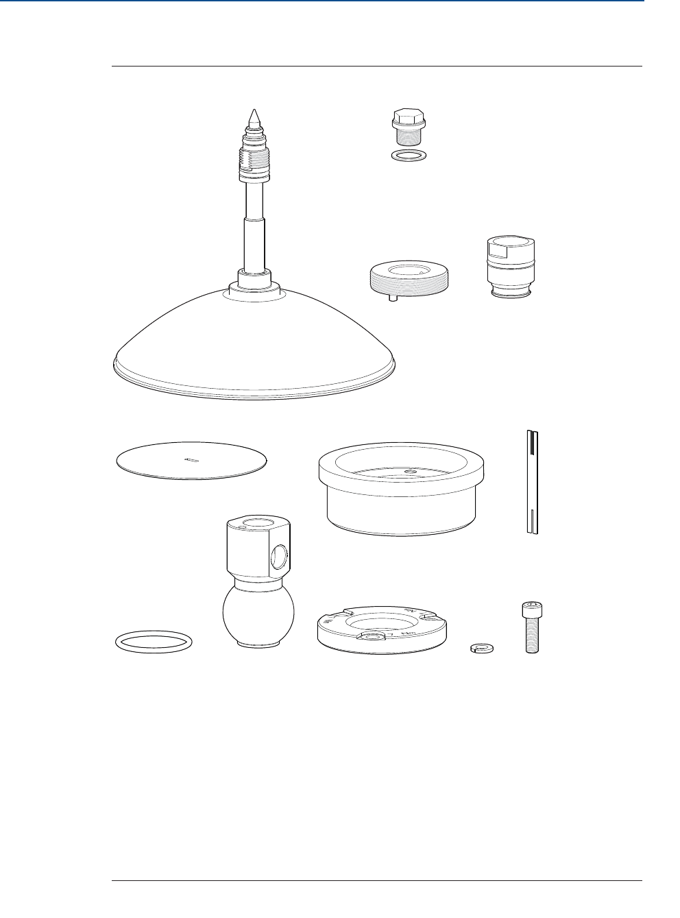
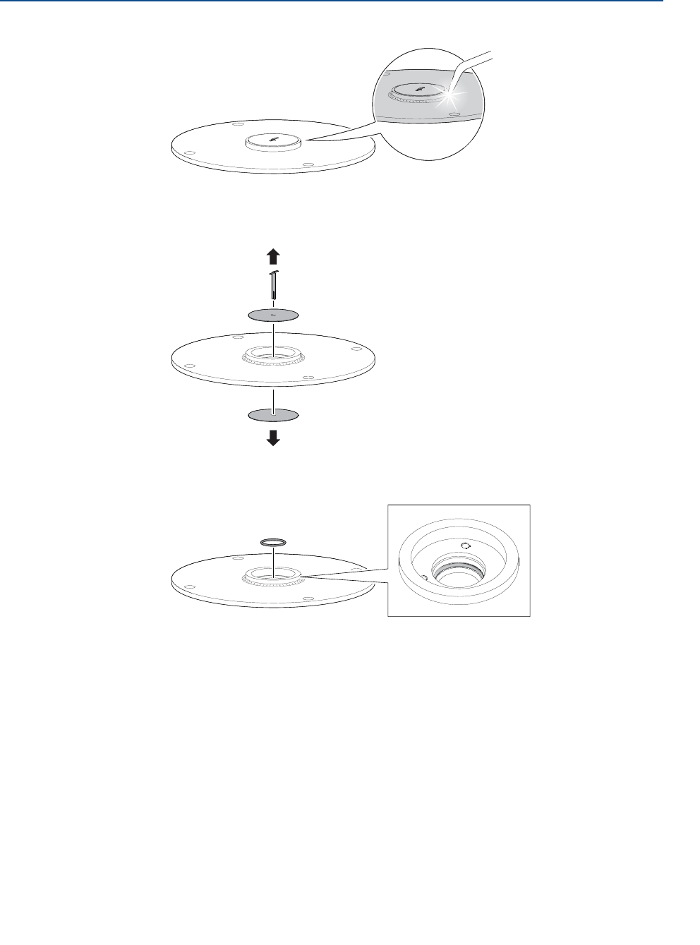
3.5.2 Threaded version
Figure 3-11. Components
A. Antenna
B. Purge plug kit (optional with order)
P/N 05400-1200-0001
C. Threaded sleeve
D. M20 adapter
E. Lock nut G 3½" (optional with order)
P/N 05400-1200-0002
F. Antenna adapter with ball joint
G. O-ring
2x
1x
E
1x
F
1x
G
1x
D
1x
C
1x
B
1x
A
39
Reference Manual
00809-0100-4408, Rev AA
Mechanical Installation
November 2016
Mechanical Installation
PRELIMINARY
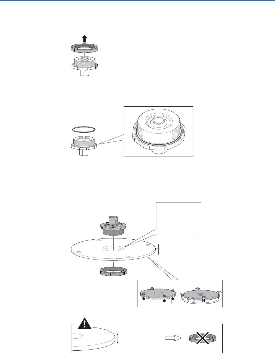
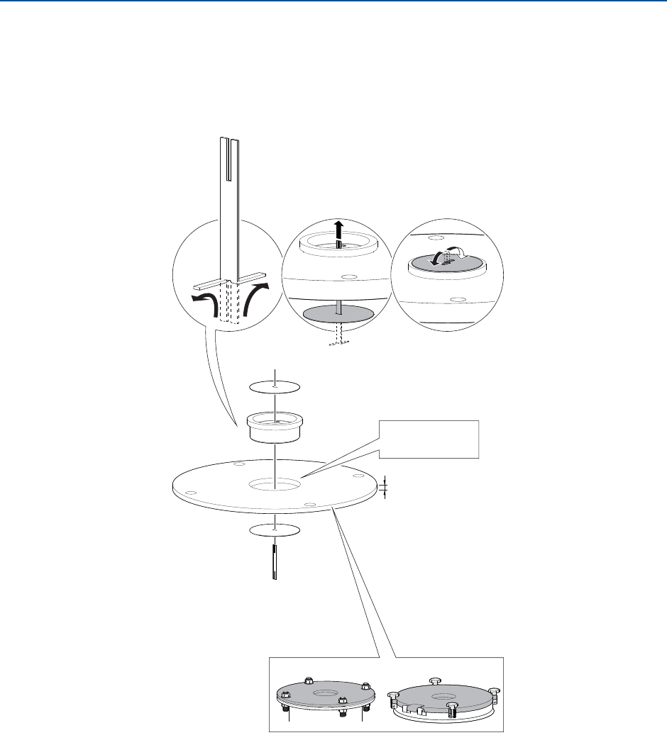
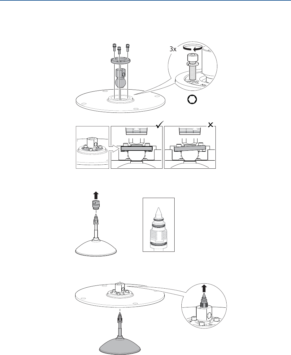
Procedure
1. Remove the lock nut (if applicable).
2. Mount the O-ring.
3. Mount the antenna adapter on flange/manhole cover.
Ensure the antenna adapter fits tightly to the flange/manhole cover.
E
F
G
Ø 3.98 ± 0.02 in.
(Ø 101 ± 0.6 mm)
OR
G 3½"
Max. 1.18 in. (30 mm)
> 0.59 in. (15 mm)
40
Reference Manual
00809-0100-4408, Rev AA
Mechanical Installation
November 2016
Mechanical Installation
PRELIMINARY
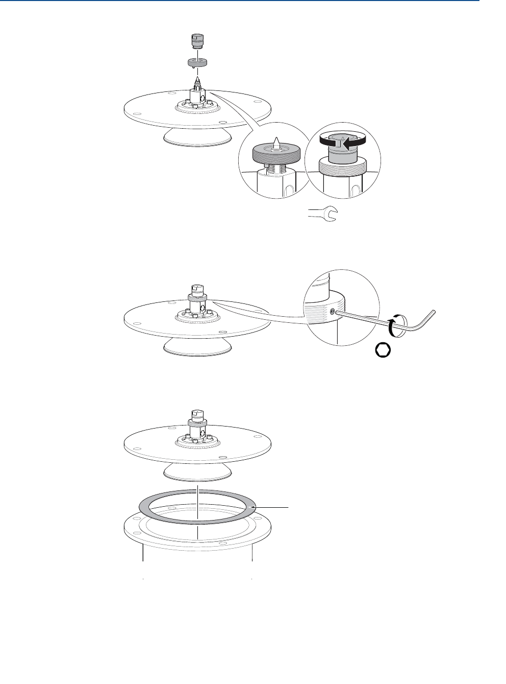
4. Remove the M20 adapter and visually inspect the O-rings for damage and dirt.
5. Carefully insert the antenna.
6. Secure the antenna.
7. Tighten the set screw.
O-rings
A
D
CD
Torque 180 in-lb (20 Nm)
27 mm
H2 mm
Torque 5 in-lb (0.5 Nm)
41
Reference Manual
00809-0100-4408, Rev AA
Mechanical Installation
November 2016
Mechanical Installation
PRELIMINARY
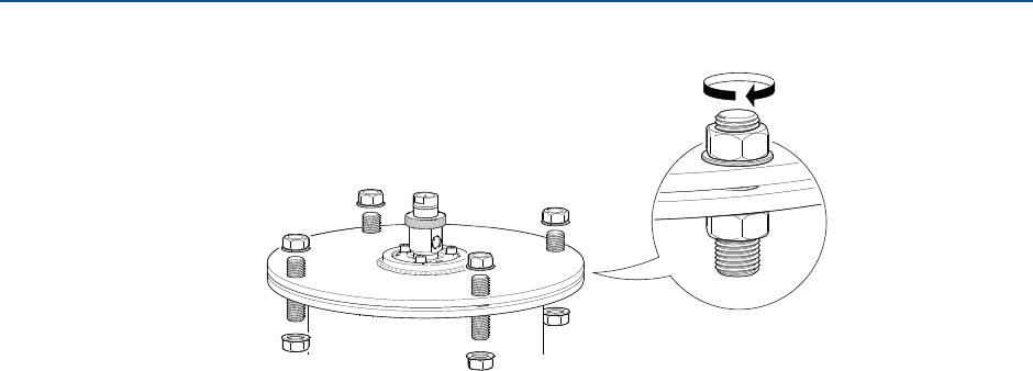
8. Lower the antenna assembly into the tank.
9. Tighten the bolts and nuts with sufficient torque for the flange and gasket choice.
10. Adjust the inclination of the antenna (see page 48).
11. Connect the air purging system (see page 51).
Gasket
42
Reference Manual
00809-0100-4408, Rev AA
Mechanical Installation
November 2016
Mechanical Installation
PRELIMINARY
3.5.3 Welded version
Figure 3-12. Components
A. Antenna
B. Purge plug kit (optional with order)
P/N 05400-1200-0001
C. Threaded sleeve
D. M20 adapter
E. Weld protection plate
F. Flange ball
G. Weld protection bar
H. O-ring
I. Ball joint
J. Clamp flange
K. Washer
L. M8 screw
2x
E
1x
G
1x
F
1x
H
1x
J
1x
I
1x
D
1x
C
3x
K
3x
L
1x
A
1x
B
43
Reference Manual
00809-0100-4408, Rev AA
Mechanical Installation
November 2016
Mechanical Installation
PRELIMINARY
Procedure
1. Mount the protection plates to flange/manhole cover.
These plates protects the internal surfaces of the flange ball from dust and sparks
during welding.
Ø 3.94 ± 0.02 in.
(Ø 100 ± 0.5 mm)
E
F
G
E
Max. 1.18 in. (30 mm)
44
Reference Manual
00809-0100-4408, Rev AA
Mechanical Installation
November 2016
Mechanical Installation
PRELIMINARY
2. Weld the flange ball.
3. Remove the protection plates and visually inspect the internal surfaces of the
flange ball for damage and dirt.
4. Mount the O-ring.
H
45
Reference Manual
00809-0100-4408, Rev AA
Mechanical Installation
November 2016
Mechanical Installation
PRELIMINARY
5. Mount the ball joint.
a. Insert the ball joint and place the clamp flange with the “7 Nm” marking side up.
b. Gradually tighten the M8 screws.
6. Remove the M20 adapter and visually inspect the O-rings for damage and dirt.
7. Carefully insert the antenna.
H6 mm
Torque 65 in-lb (7 Nm)
K
L
J
I
O-rings
A
D
46
Reference Manual
00809-0100-4408, Rev AA
Mechanical Installation
November 2016
Mechanical Installation
PRELIMINARY
8. Secure the antenna.
9. Tighten the set screw.
10. Lower the antenna assembly into the tank.
CD
Torque 180 in-lb (20 Nm)
27 mm
H2 mm
Torque 5 in-lb (0.5 Nm)
Gasket
47
Reference Manual
00809-0100-4408, Rev AA
Mechanical Installation
November 2016
Mechanical Installation
PRELIMINARY
11. Tighten the bolts and nuts with sufficient torque for the flange and gasket choice.
12. Adjust the inclination of the antenna (see page 48).
13. Connect the air purging system (see page 51).
48
Reference Manual
00809-0100-4408, Rev AA
Mechanical Installation
November 2016
Mechanical Installation
PRELIMINARY
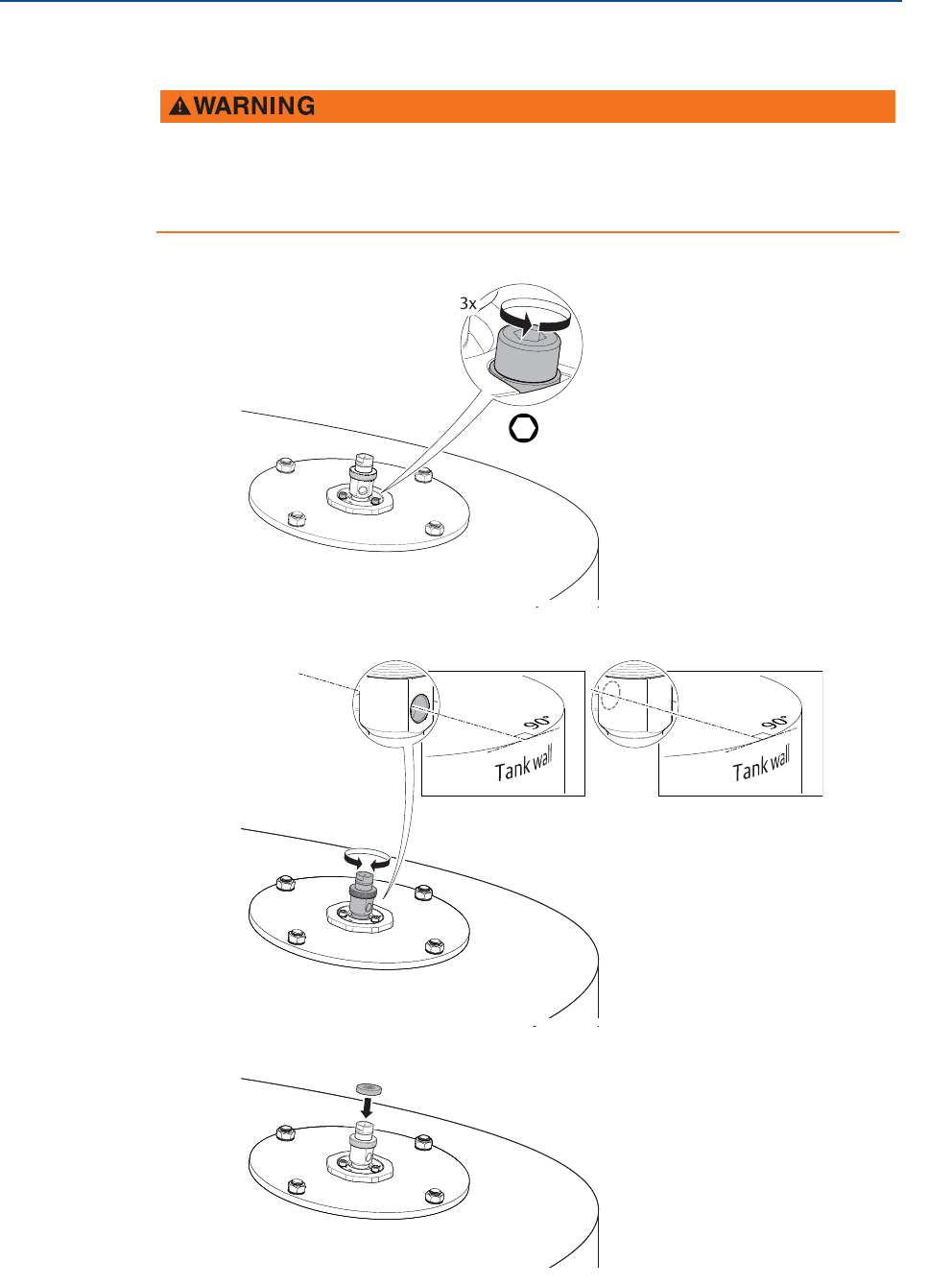
3.5.4 Adjust the inclination of the antenna
1. Loosen the M8 screws until the transmitter can rotate smoothly.
2. Rotate the antenna so the air purge connection is directed toward the tank wall.
3. Place the circular level on top of the antenna assembly.
Contents may be under pressure.
Do not loosen the M8 screws while in operation. Attempting to do so may release
pressurized gases, resulting in serious injury or death.
H6 mm
or
49
Reference Manual
00809-0100-4408, Rev AA
Mechanical Installation
November 2016
Mechanical Installation
PRELIMINARY
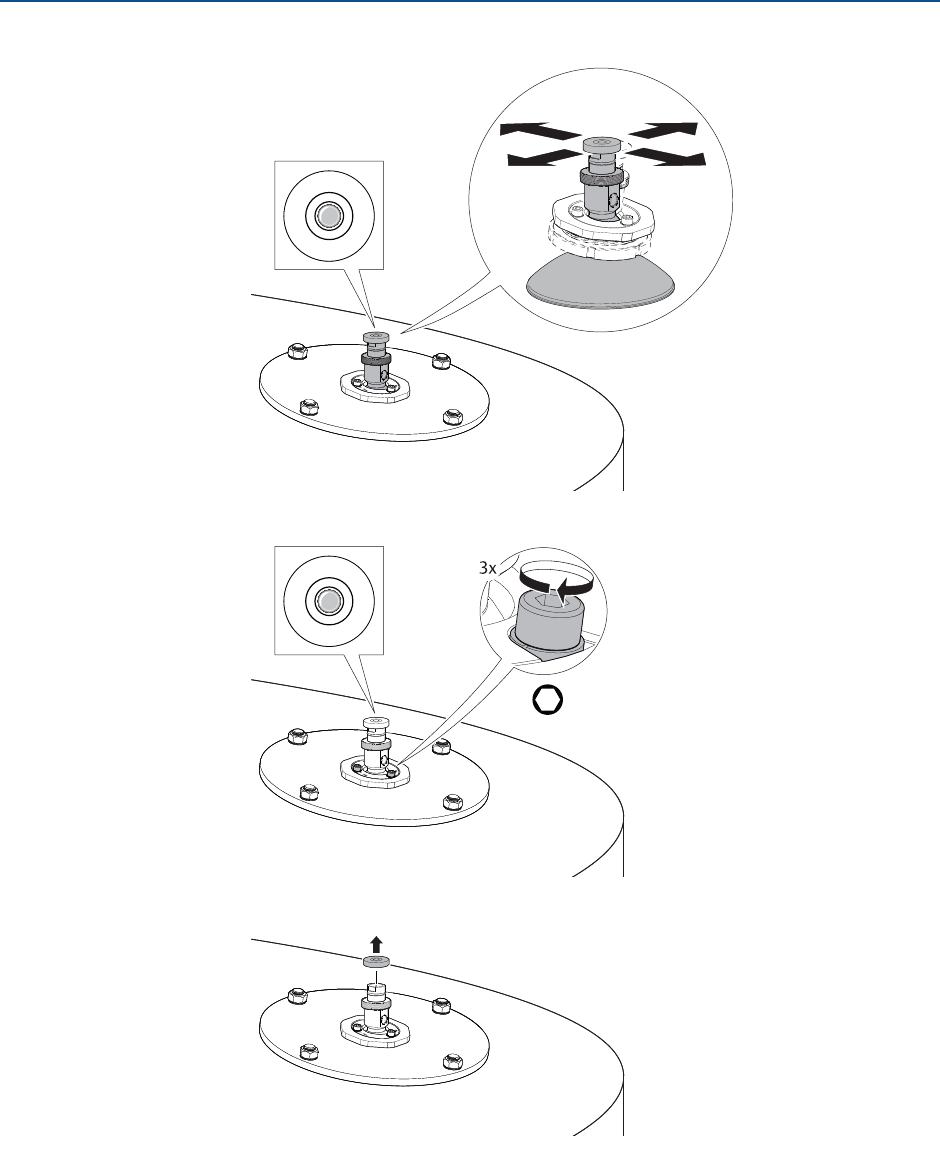
4. Adjust the inclination of the antenna.
5. Gradually tighten the M8 screws.
6. Remove the circular level.
H6 mm
Torque 65 in-lb (7 Nm)