Rosemount Tank Radar 5408T Rosemount 5408 Level Transmitter User Manual
Rosemount Tank Radar AB Rosemount 5408 Level Transmitter
UserManual.wiki
>
Rosemount Tank Radar
>
5408T User Manual
>
manual_part2
Contents
1.
manual_part2
2.
manual _part1
manual_part2
Navigation menu
Upload a User Manual
Namespaces
Wiki Guide
HTML
PDF
Info
Views
User Manual
Discussion / Help
Navigation
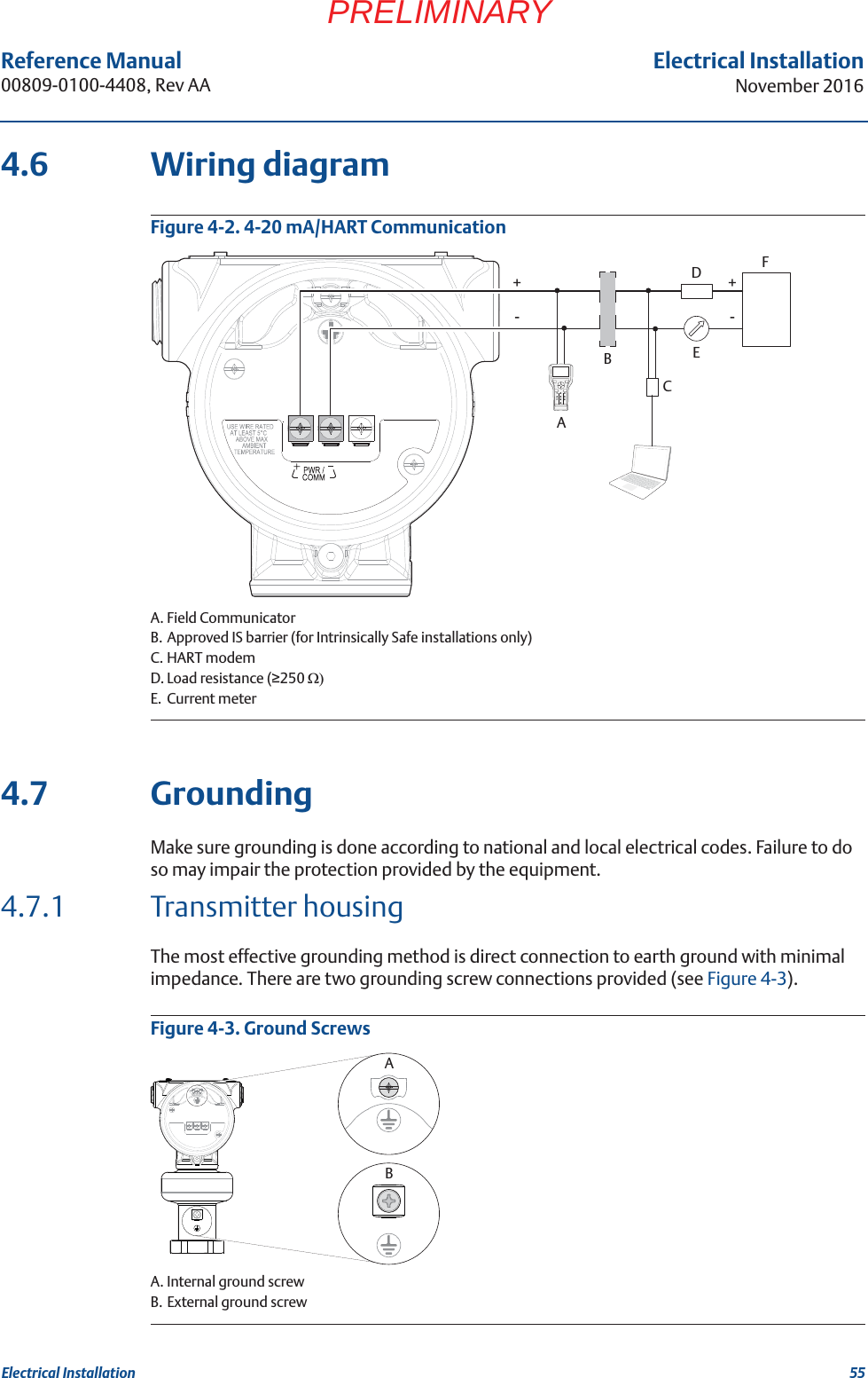
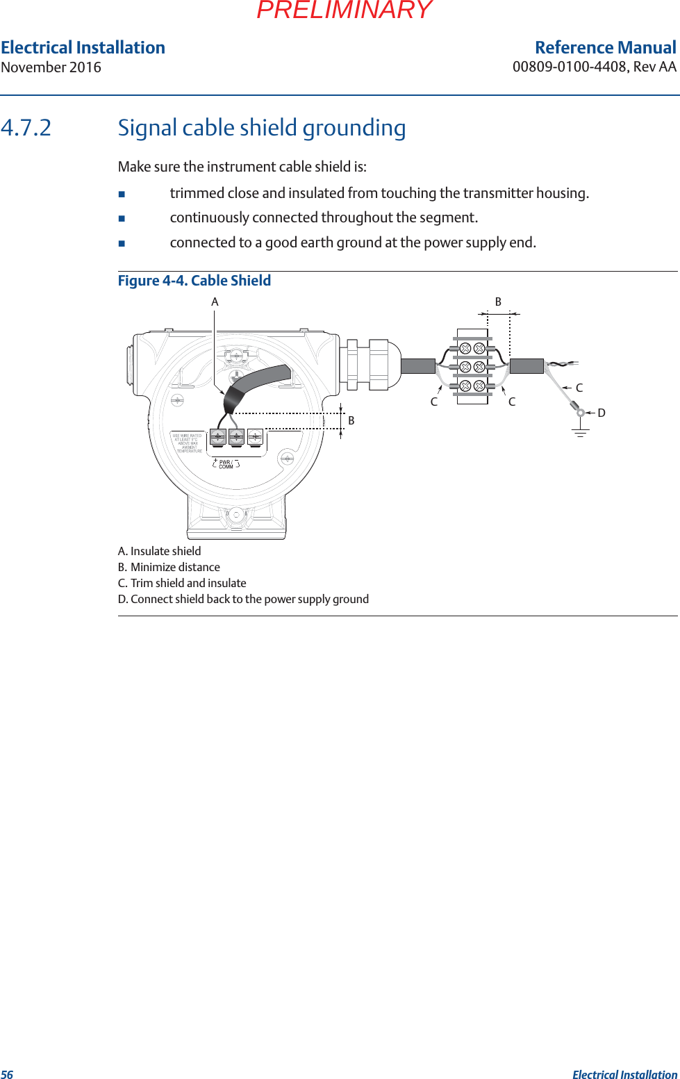
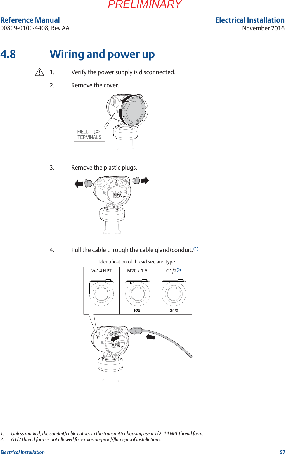
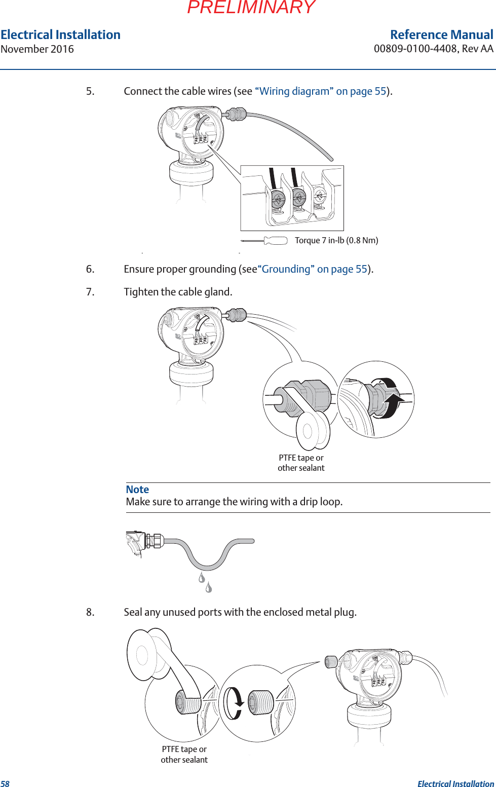
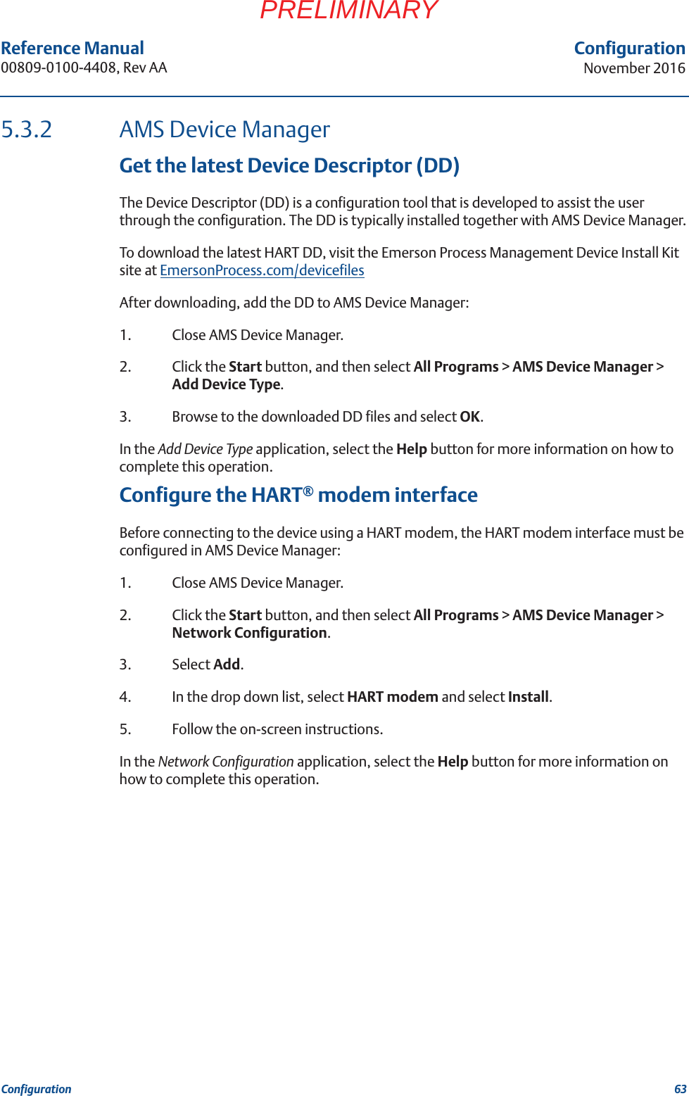
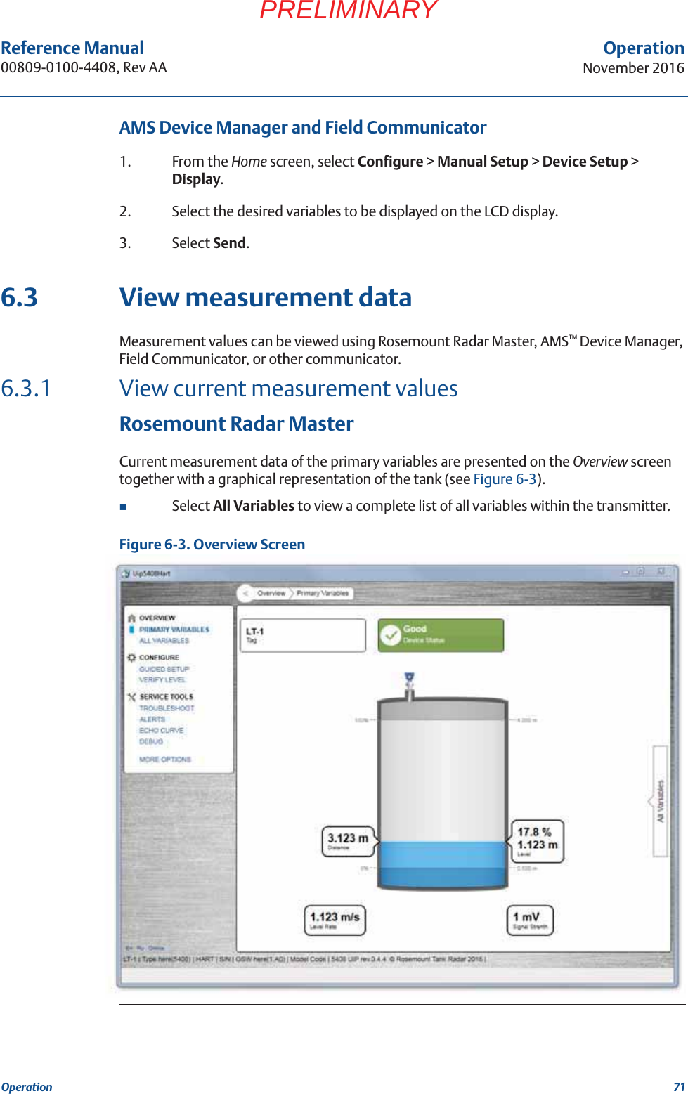
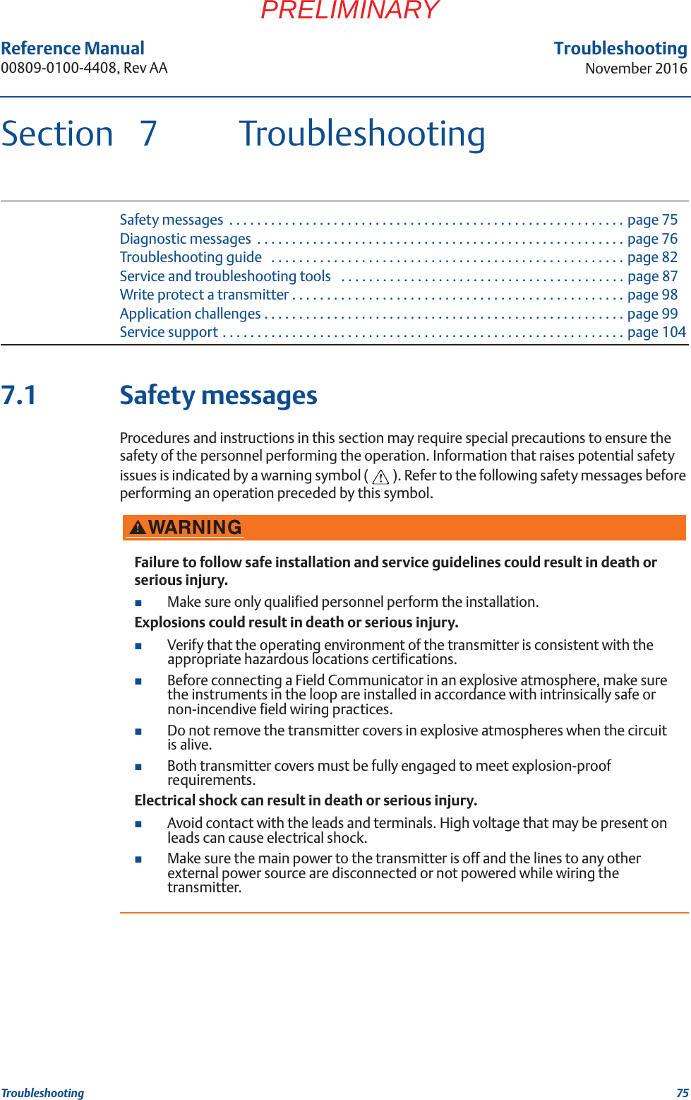
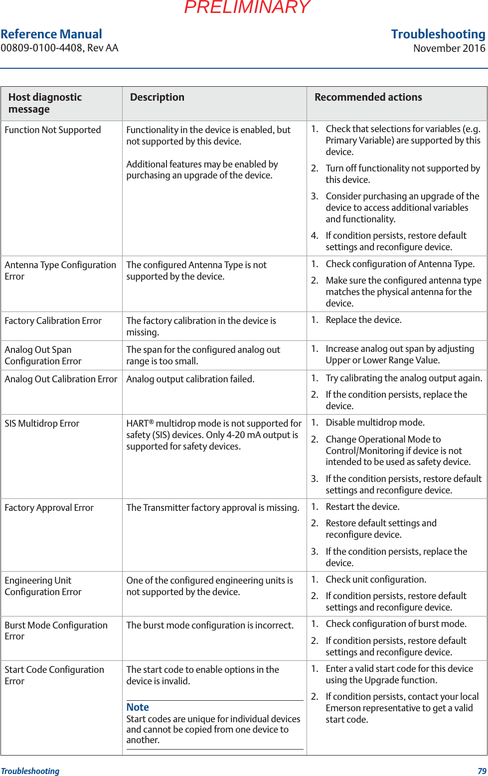
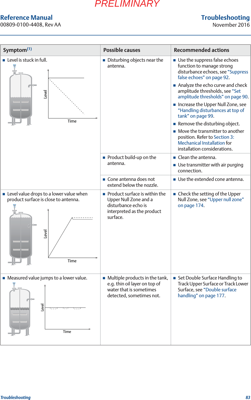
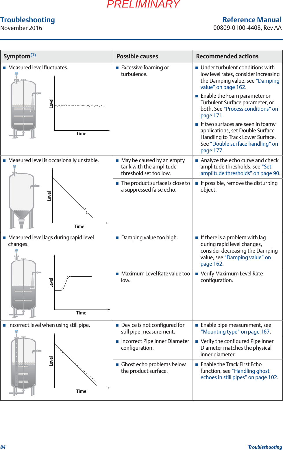
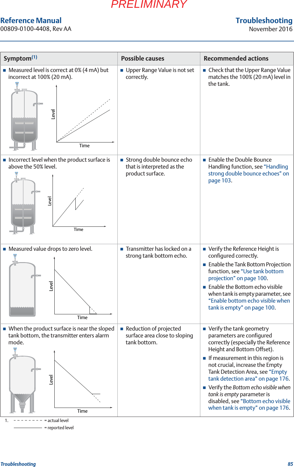
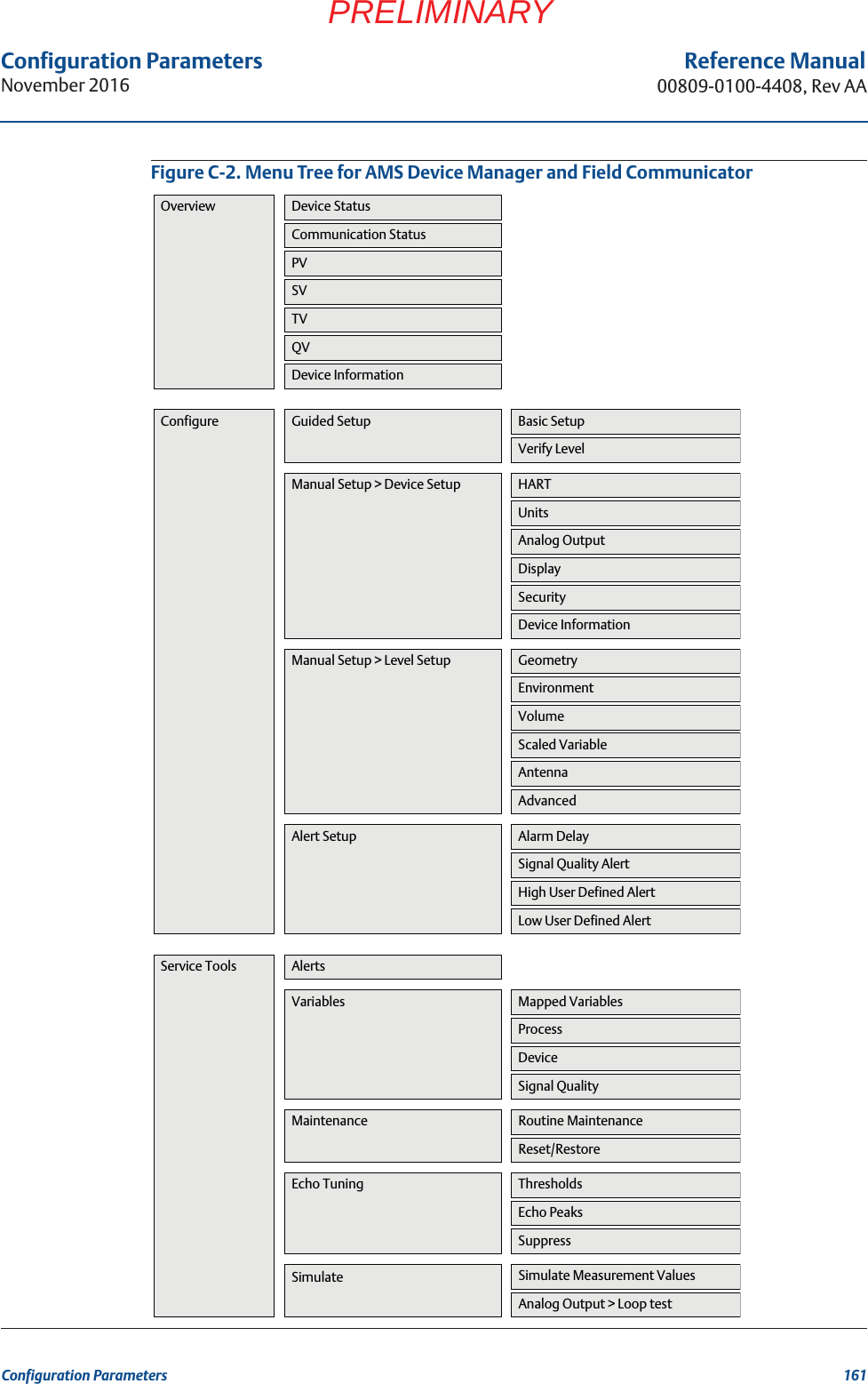
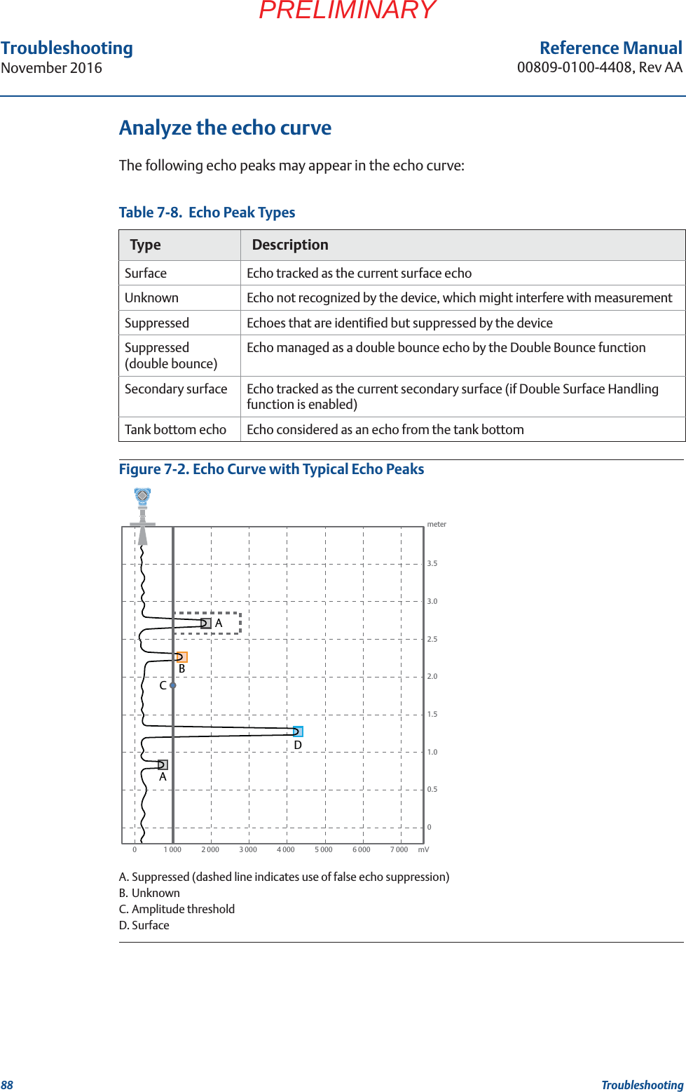
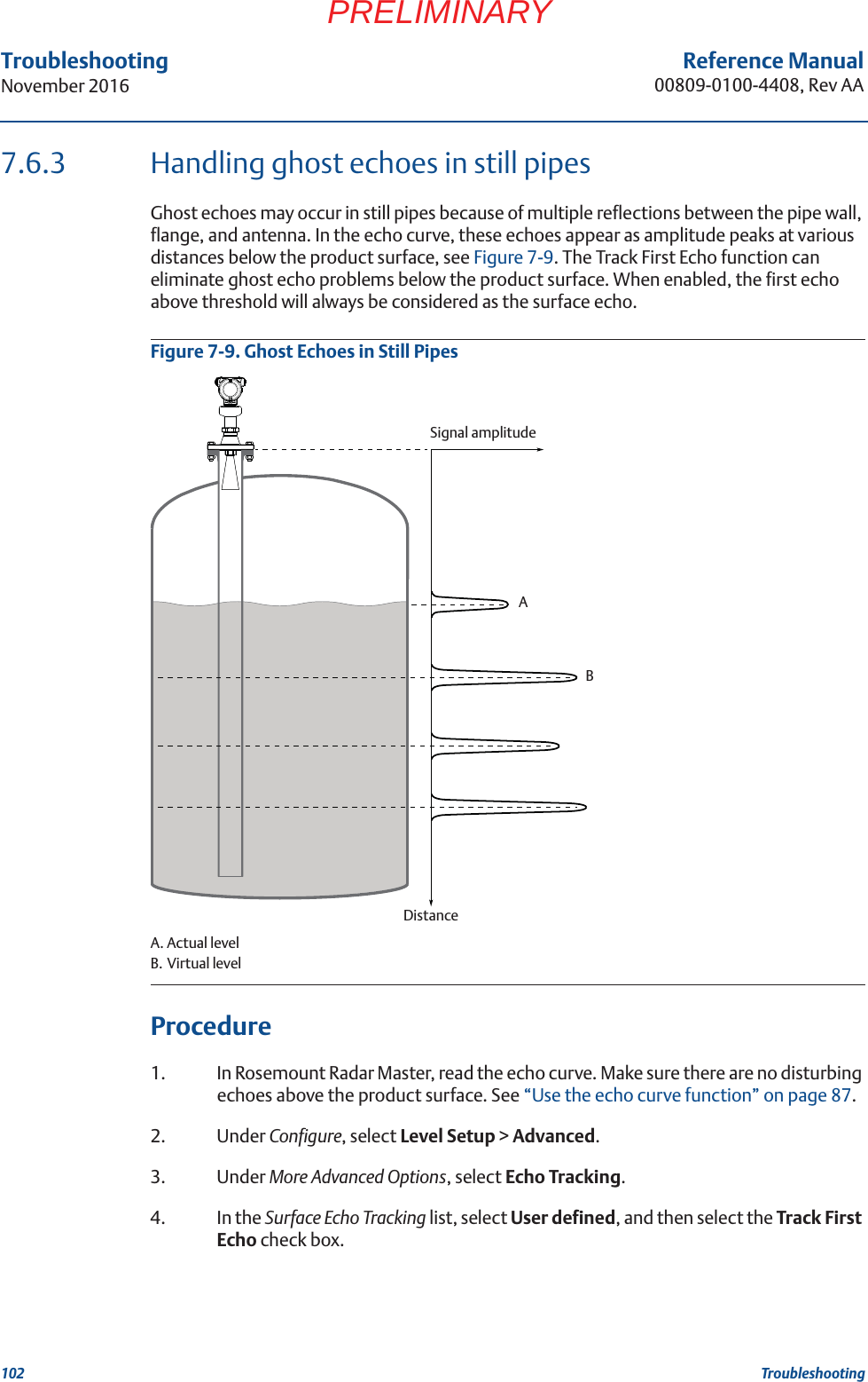
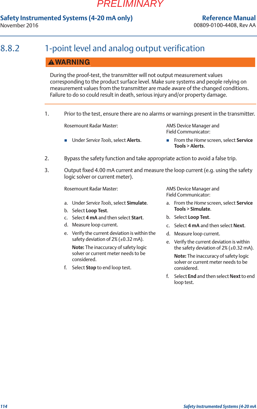
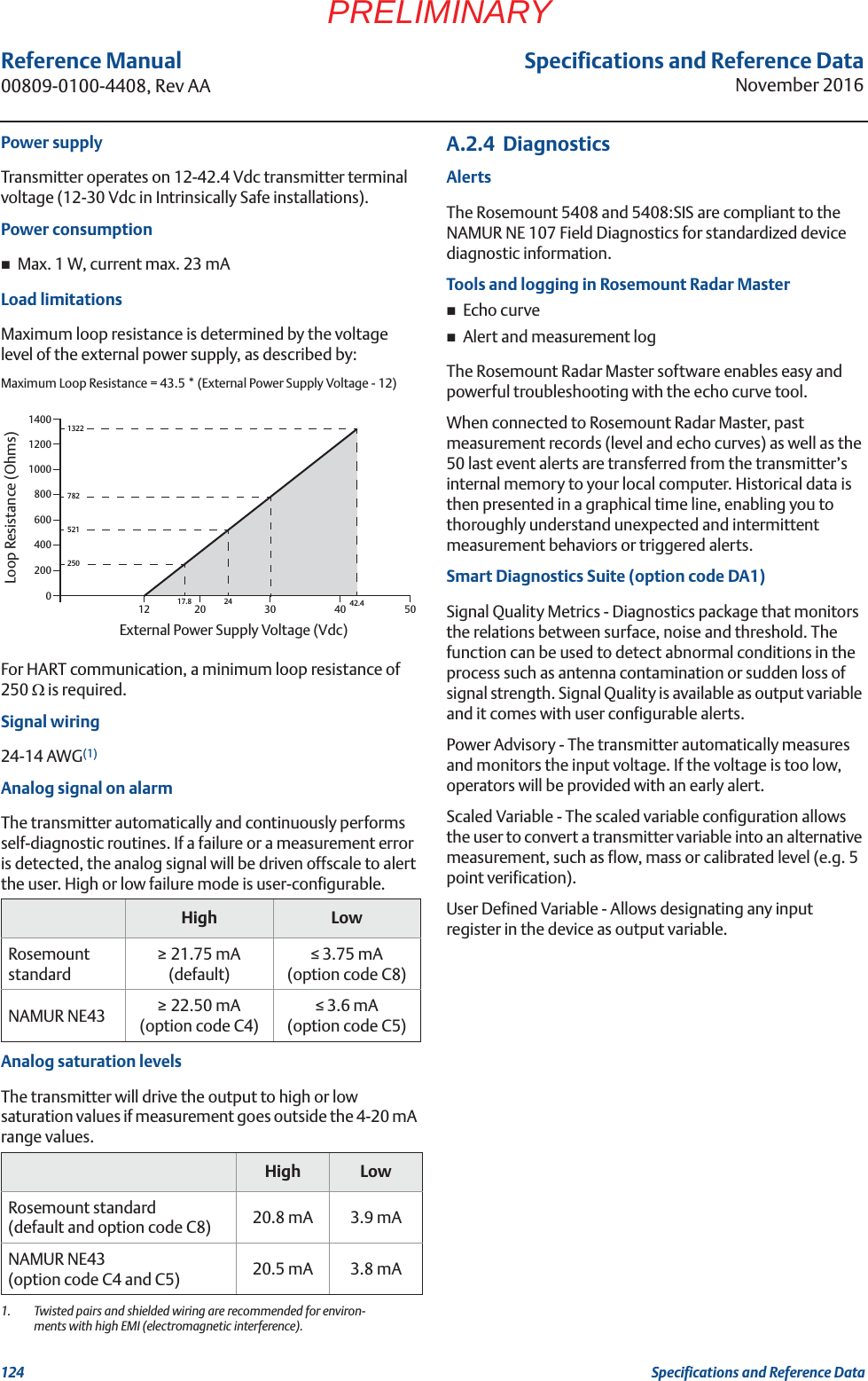
![87Reference Manual 00809-0100-4408, Rev AATroubleshootingNovember 2016TroubleshootingPRELIMINARY7.4 Service and troubleshooting toolsThis section briefly describes tools and functions in the Rosemount Radar Master, AMS Device Manager, and Field Communicator, which may be useful for service and troubleshooting of the Rosemount 5408 and 5408:SIS Level Transmitters.7.4.1 Use the echo curve functionThe Rosemount Radar Master software includes functions for viewing and recording single instances or movies of the echo curve. The echo curve represents the tank, as seen by the radar transmitter. Each peak corresponds to a strong reflection of the radar signal.When connected to Rosemount Radar Master, past measurement records and echo curves including the 10 highest peaks, as well as the 50 last event alerts are automatically transferred from the transmitter’s internal memory to the hard drive on your local computer. Past measurement records are then available the next time you connect to the transmitter using the level trend timeline (see Figure 7-1).Measurement problems can be understood by studying the position and amplitude of the different peaks. Additionally, the recorded echo curves give insight into unexpected and intermittent measurement behaviors, for instance, at the time of the triggered alert. Read the echo curveTo read the echo curve in Rosemount Radar Master:1. Under Service Tools, select Echo Curve. 2. Select Play.Figure 7-1. Echo Curve[PLACEHOLDER]](https://usermanual.wiki/Rosemount-Tank-Radar/5408T.manual-part2/User-Guide-3271963-Page-38.png)
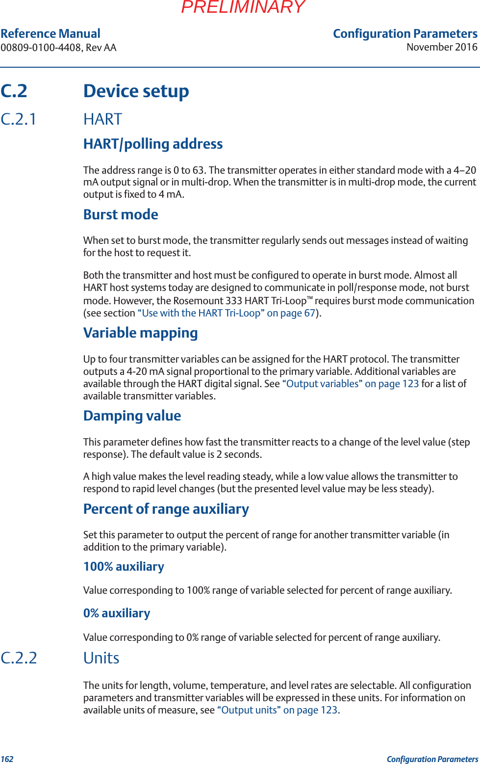
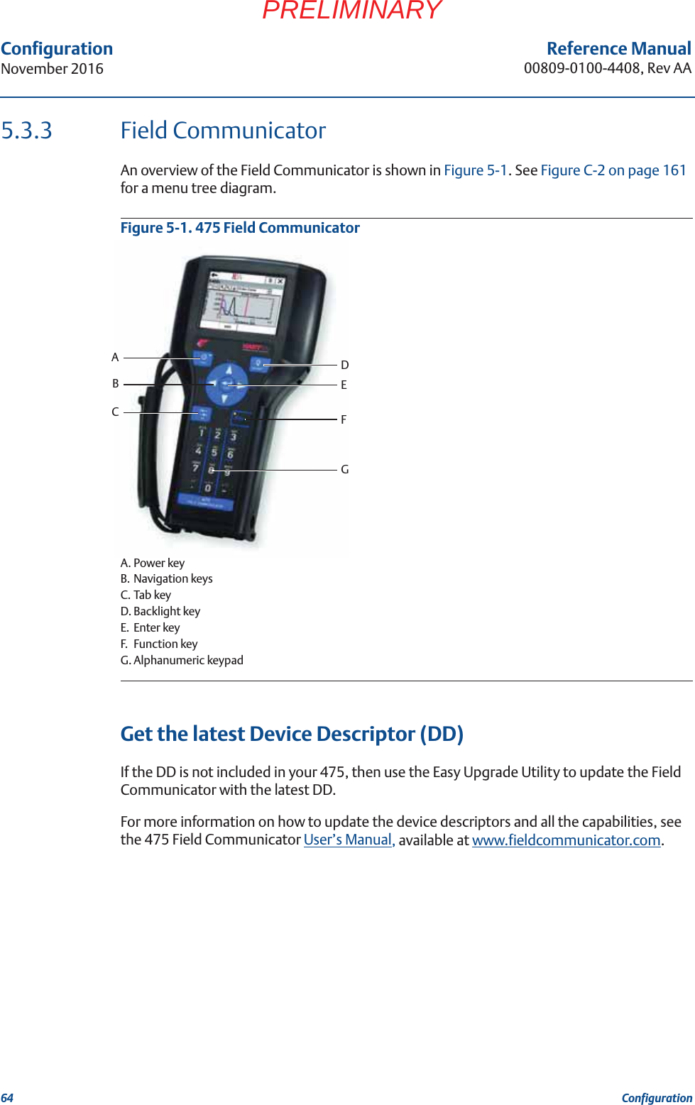
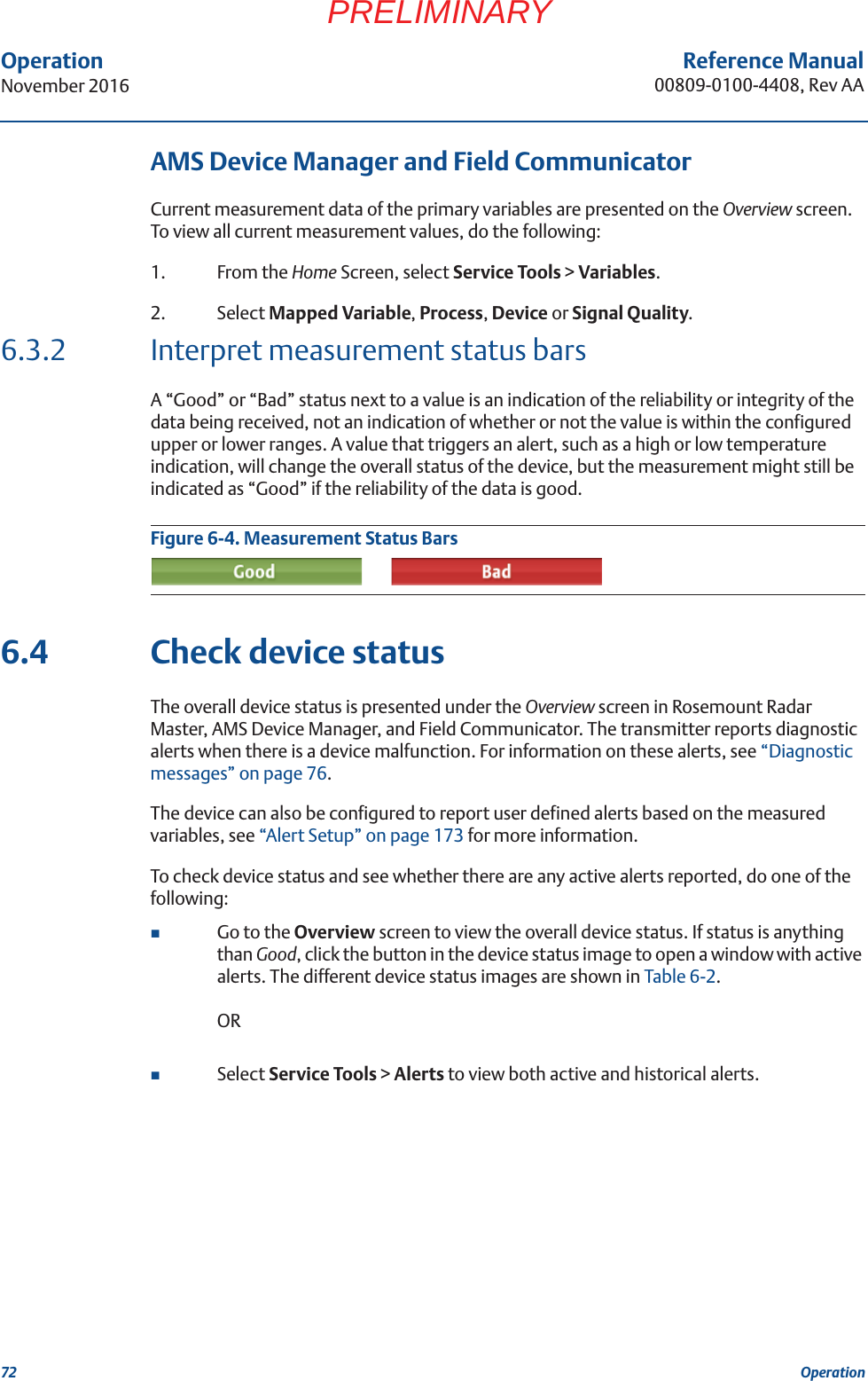
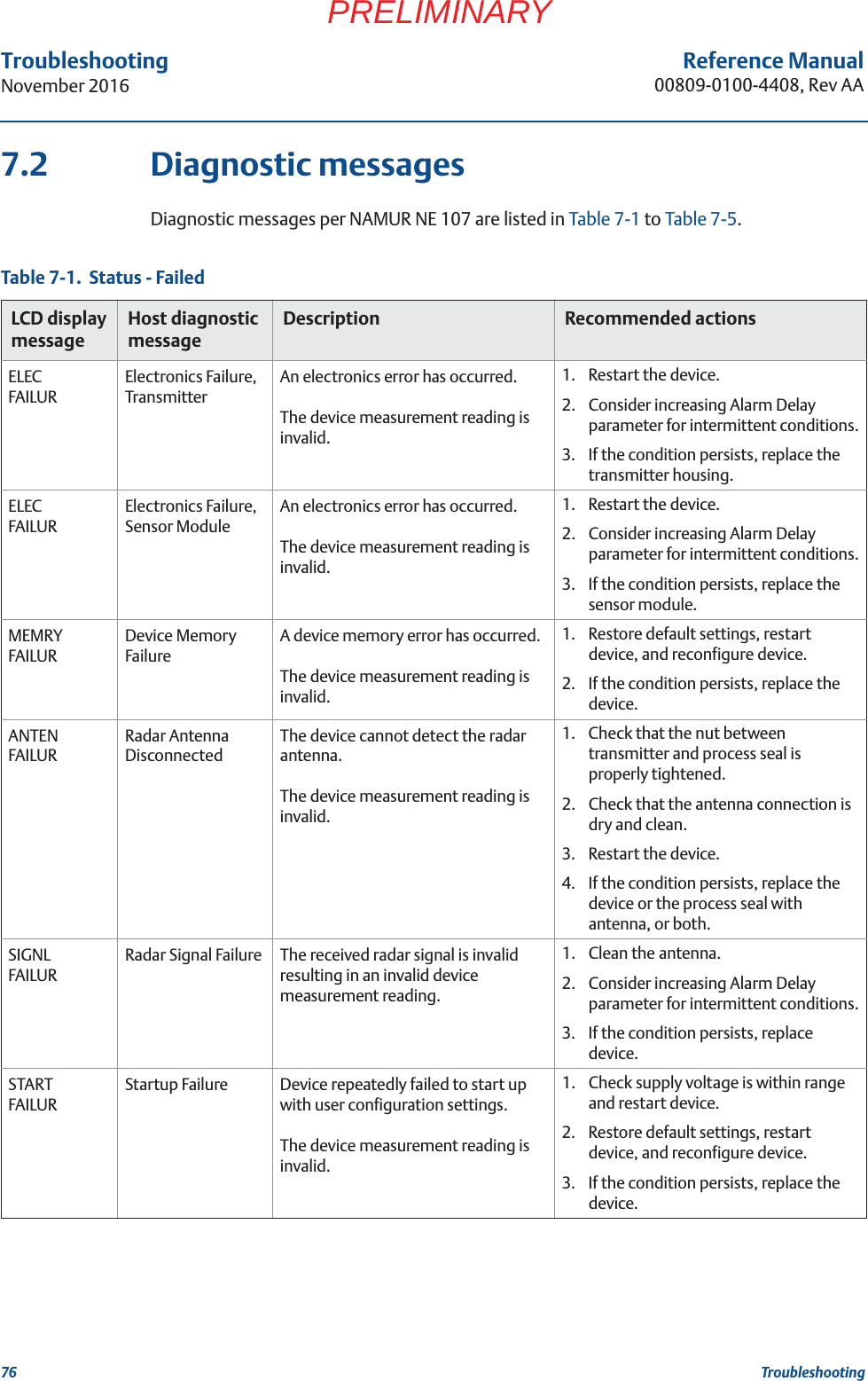
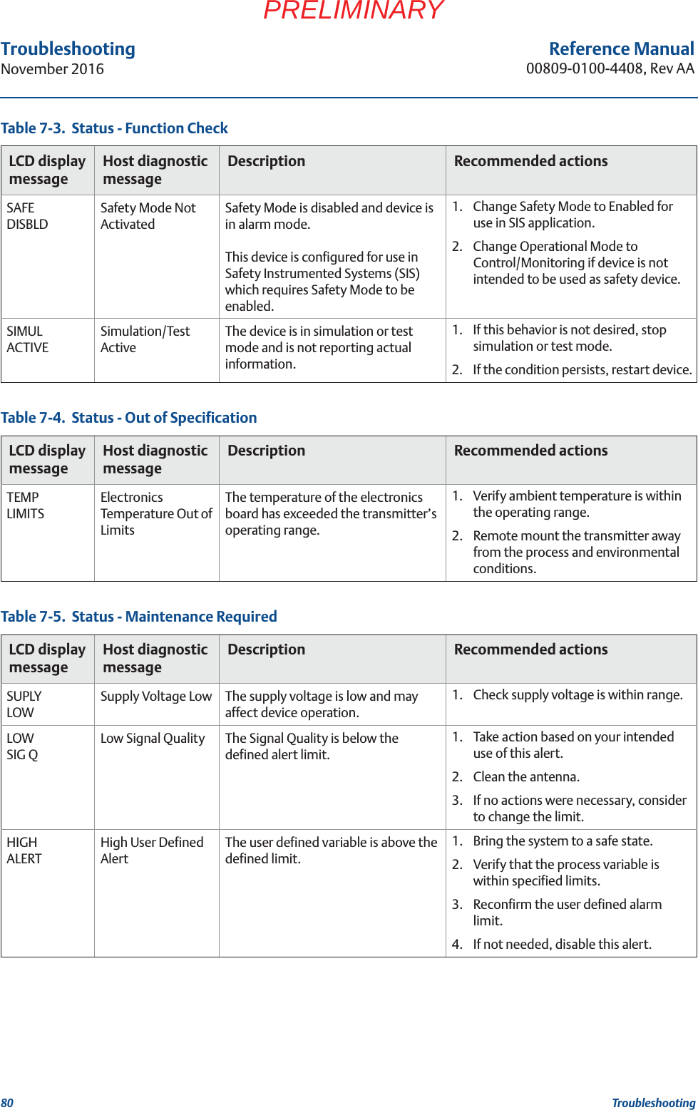
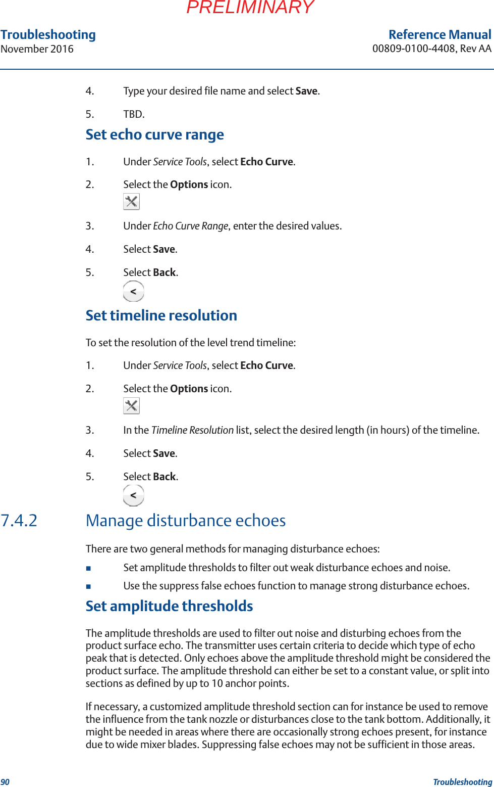
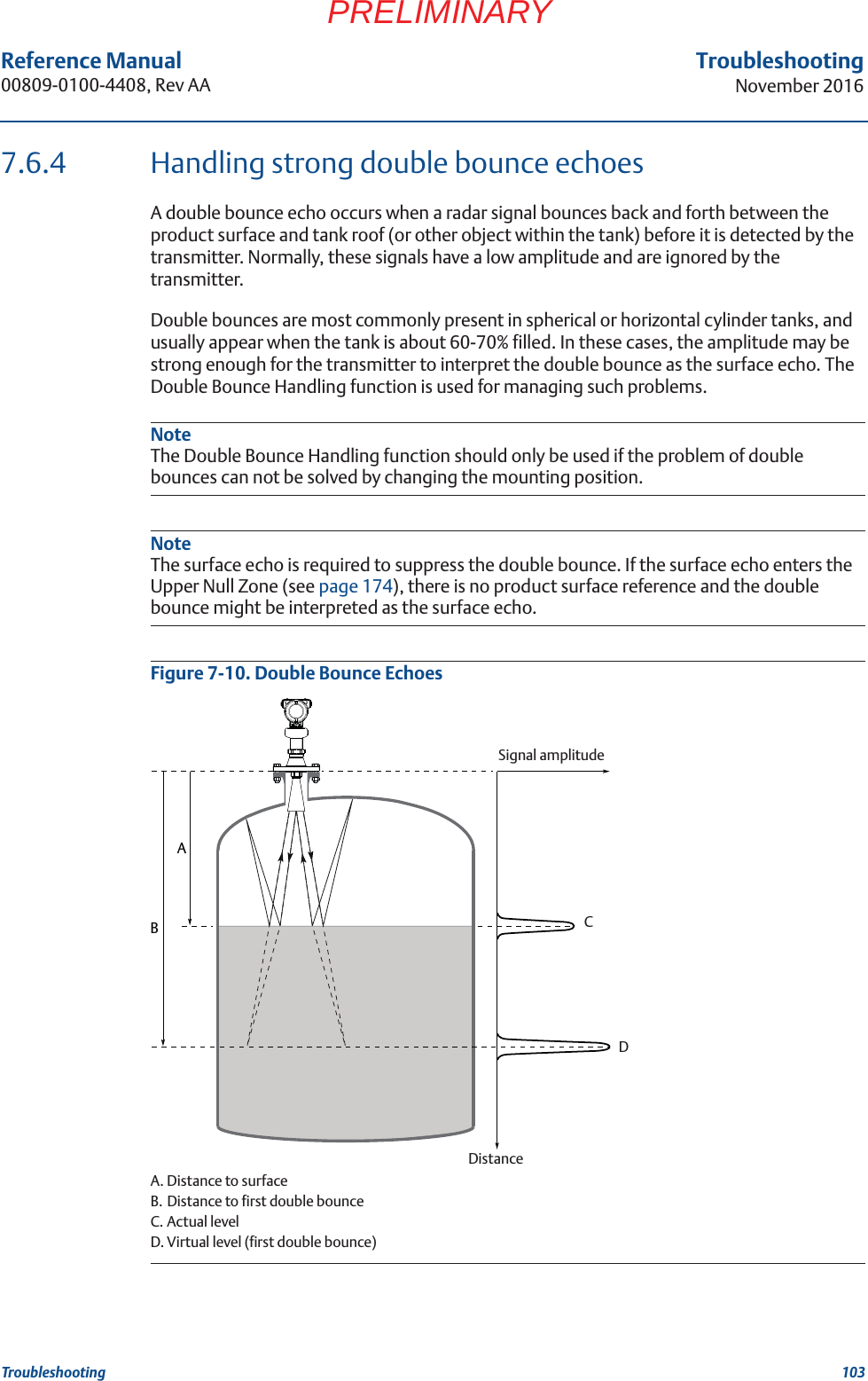
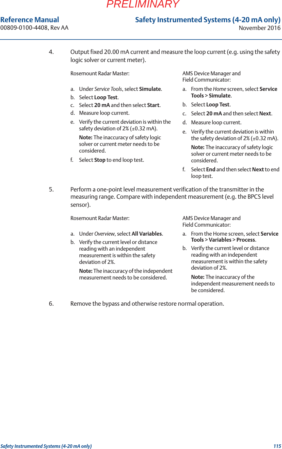
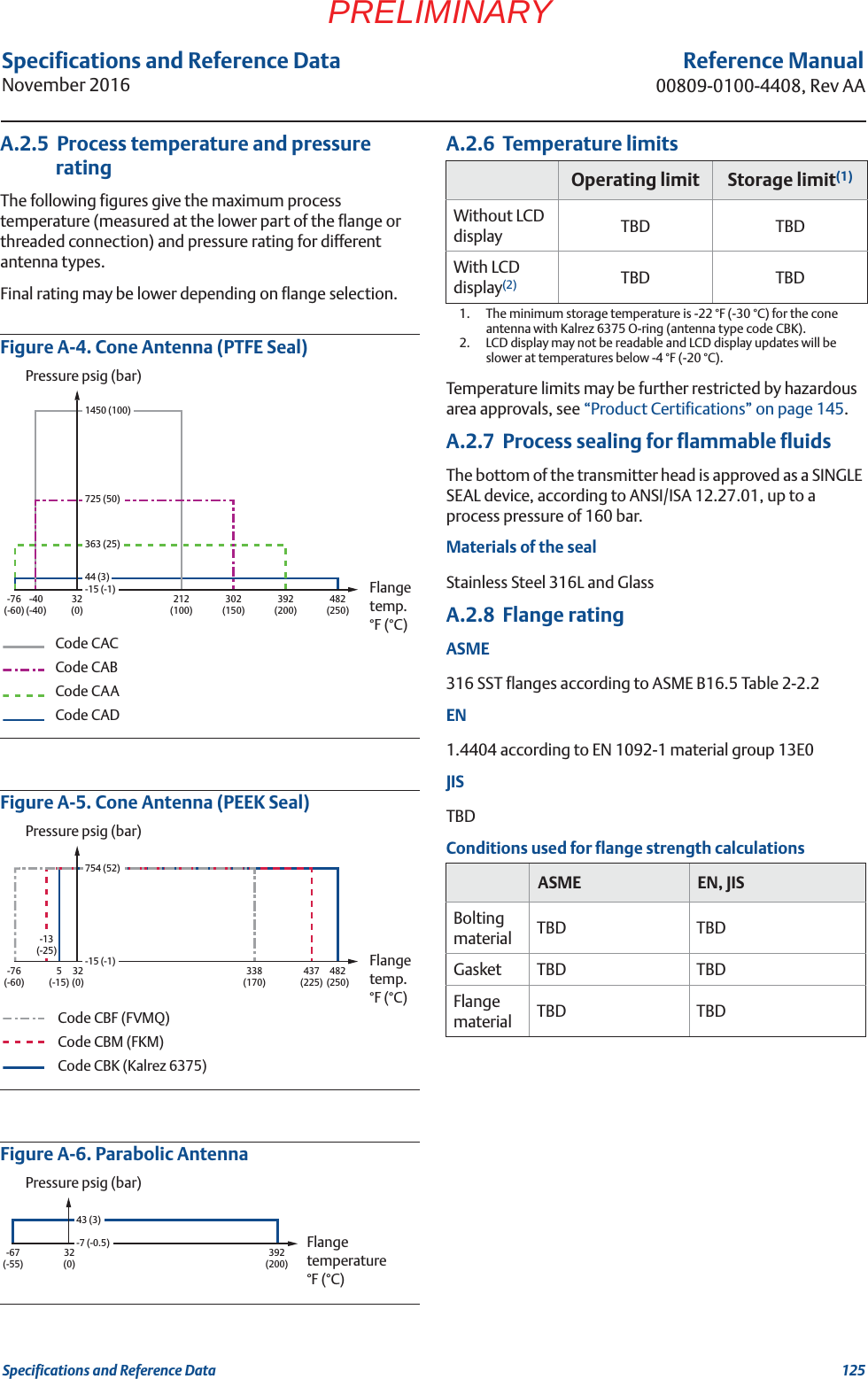
![89Reference Manual 00809-0100-4408, Rev AATroubleshootingNovember 2016TroubleshootingPRELIMINARYView level trends and historical echo curvesTo go to a desired point in the displayed part of the timeline:Drag the slider, or click anywhere in the timeline.To move the timeline forward or backward:Click the left or right arrow, or click and drag anywhere in the timeline.TipTo speed up the upload time of historical data, select Pause to halt the new echo curve reading. Reading new echo curves have priority over uploading previously recorded data to the timeline.View active/historical alertsIn the timeline, click the left or right arrow to scroll to the alert, and then select the alert icon for details.Figure 7-3. Level Trend TimelineA. Play or pauseB. Click left or right arrow, or click and drag anywhere in the timeline, to move the timeline forward or backward.C. Click the alert icon for details.D. Drag the slider, or click anywhere in the timeline, to go to a desired point in the displayed part of the timeline.E. Export echo curvesF. OptionsPlay echo curve movies 1. Drag the slider to desired start point, or click the start point in the timeline.2. Select Play.Export echo curve movies1. Under Service Tools, select Echo Curve.2. Select the Export icon.3. Browse to the desired directory.A DB B E F[PLACEHOLDER]C](https://usermanual.wiki/Rosemount-Tank-Radar/5408T.manual-part2/User-Guide-3271963-Page-40.png)
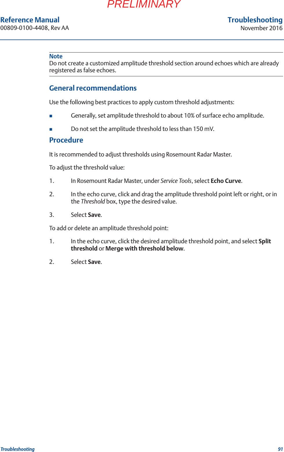
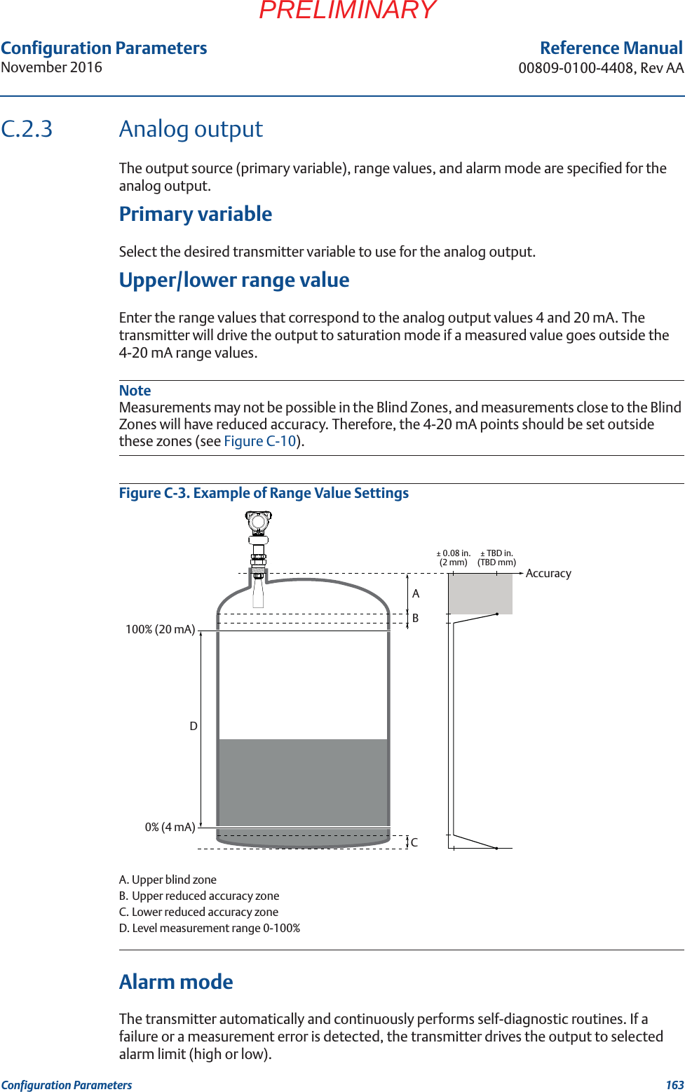
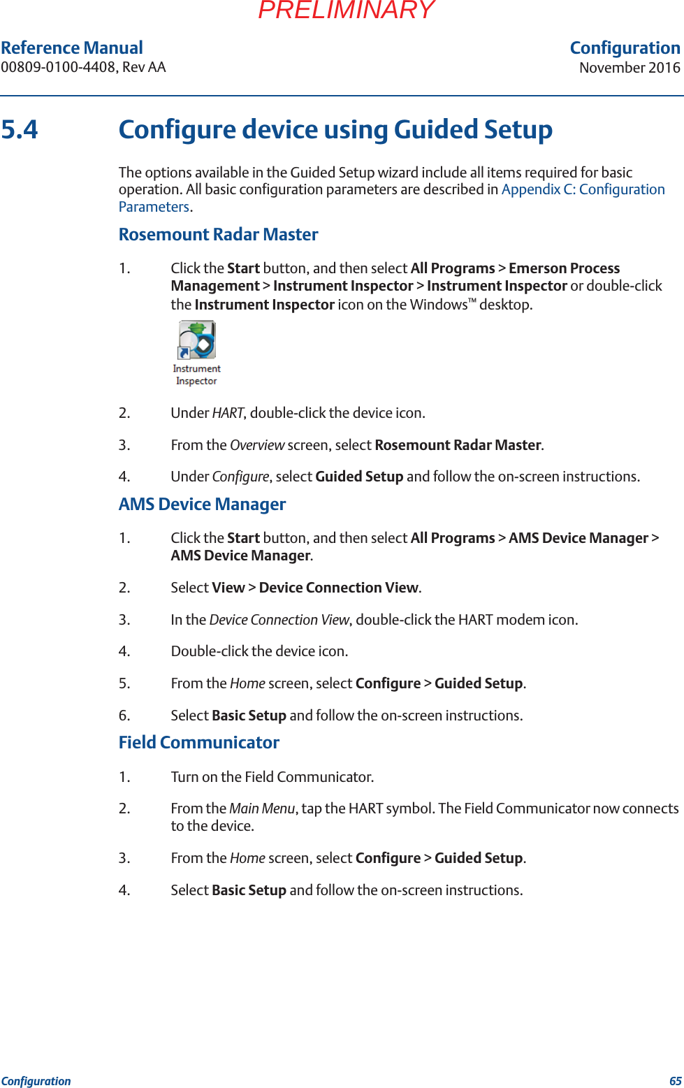
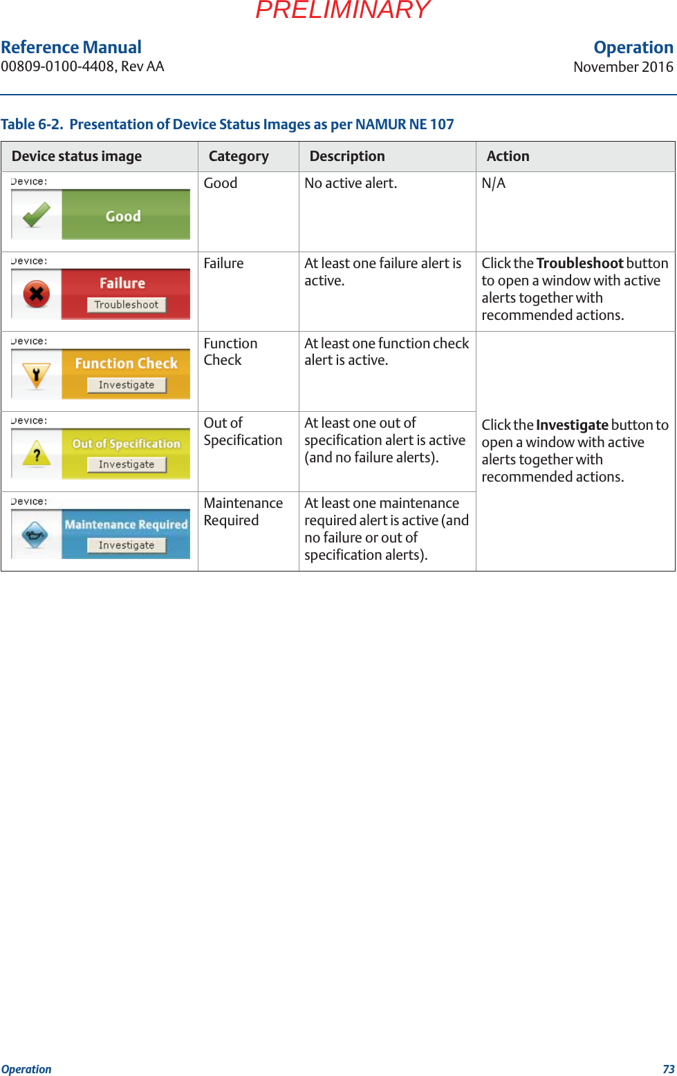
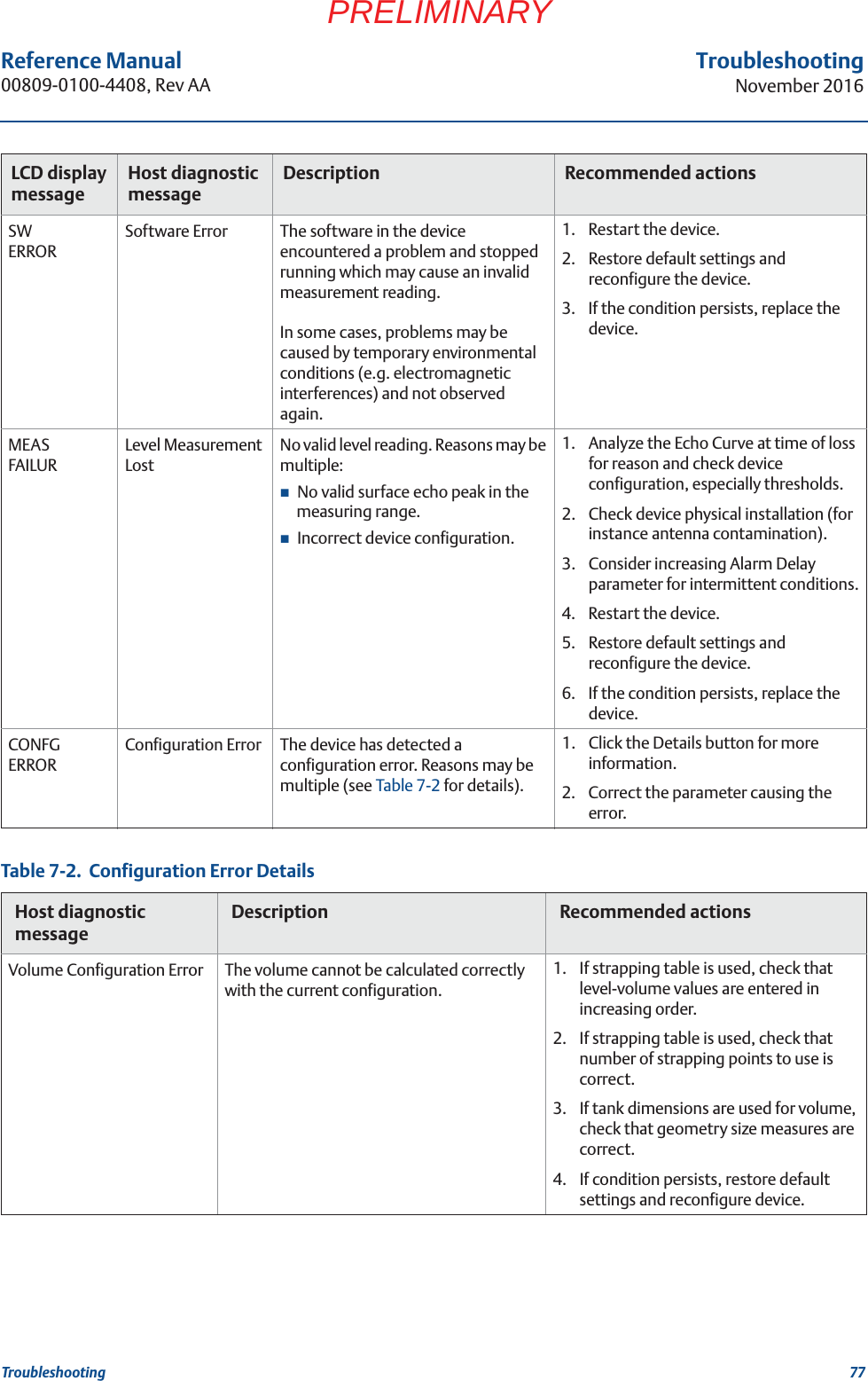
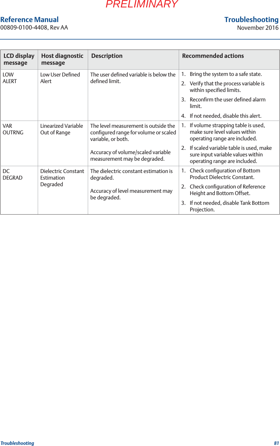
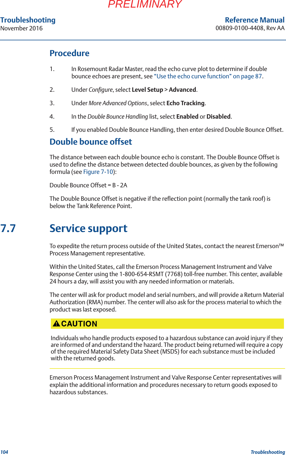
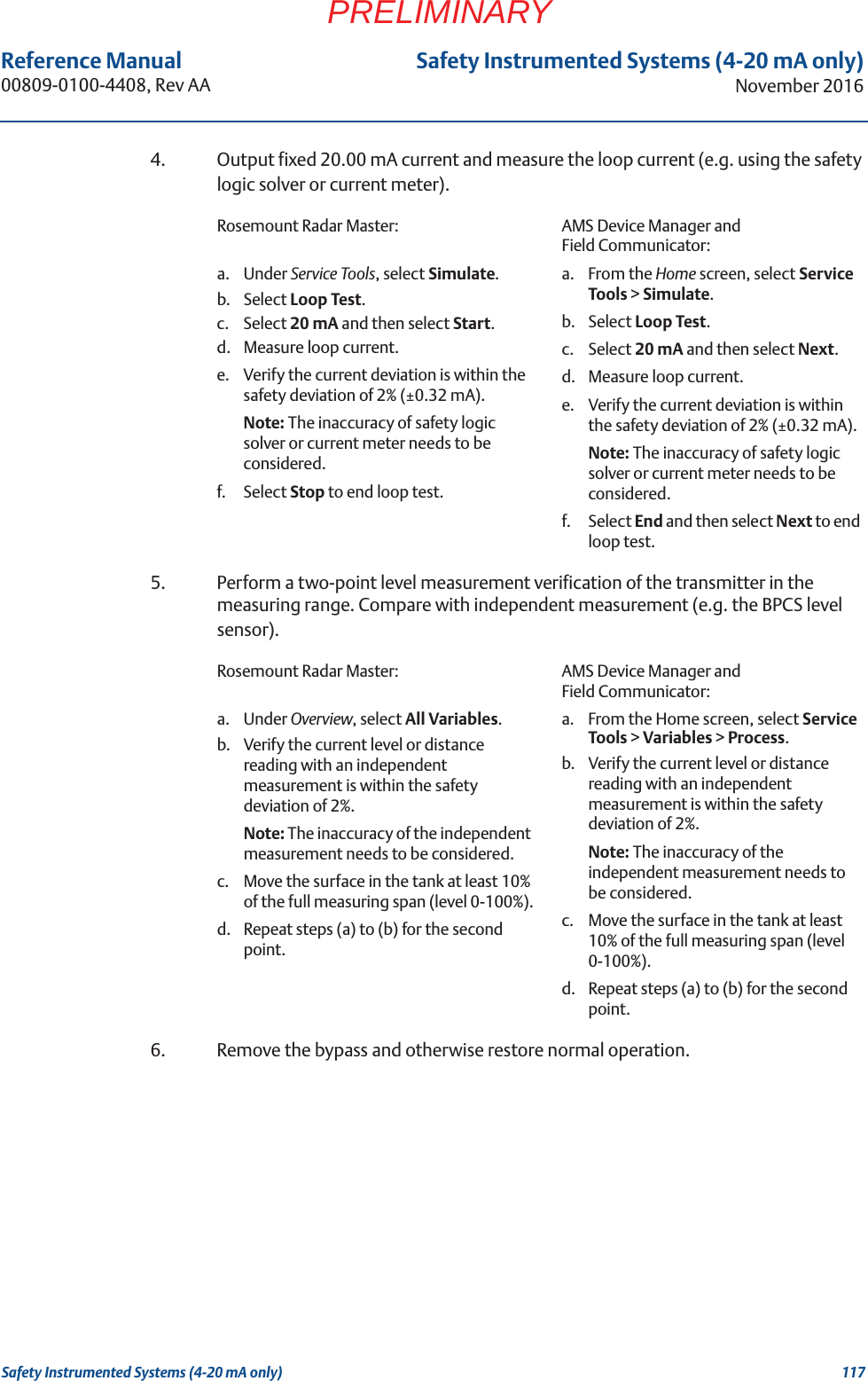
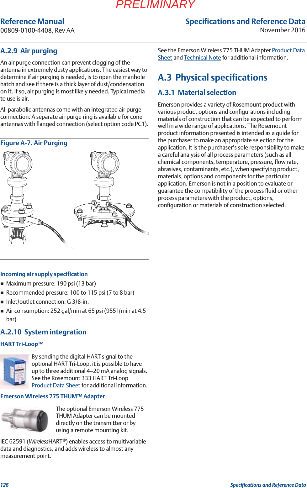
![92Reference Manual00809-0100-4408, Rev AATroubleshootingNovember 2016TroubleshootingPRELIMINARYTo set the endpoint of a threshold segment:1. In the echo curve, click and drag the endpoint up or down, or in the Split level box, type the desired value.2. Select Save.Figure 7-4. Adjust Amplitude ThresholdsA. Amplitude threshold pointB. EndpointSuppress false echoesStationary objects with horizontal surfaces may generate strong false echoes. When the surface is close to an obstruction in the tank (e.g. beams and agitators), the surface and false echoes might interfere and cause a decrease in performance.However, false echoes can be suppressed to reduce the influence of such objects, in case they cannot be totally avoided. When the surface is passing by a disturbing object, the transmitter will then measure with higher reliability, even if the surface echo is weaker than the false echo, see Figure 7-5.AB[PLACEHOLDER]](https://usermanual.wiki/Rosemount-Tank-Radar/5408T.manual-part2/User-Guide-3271963-Page-43.png)
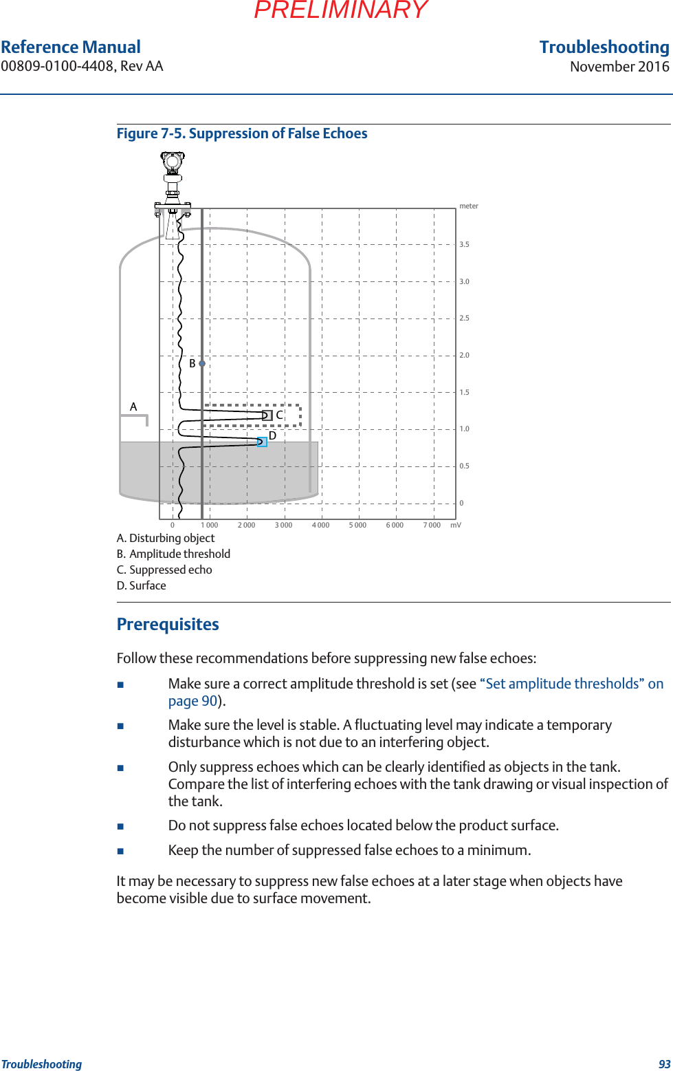
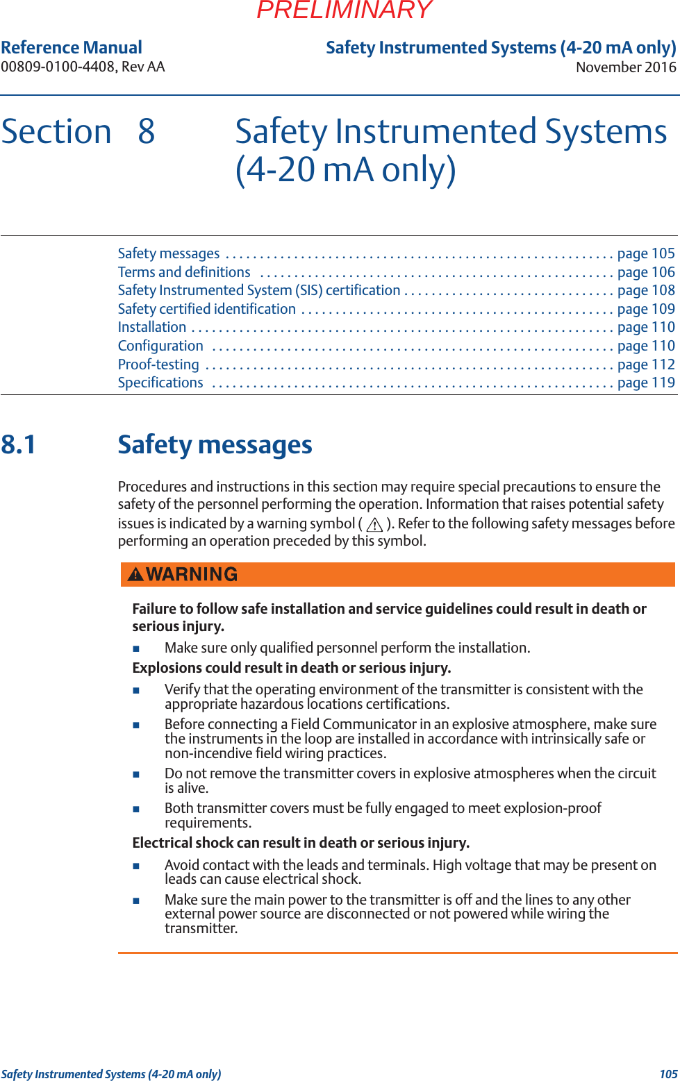

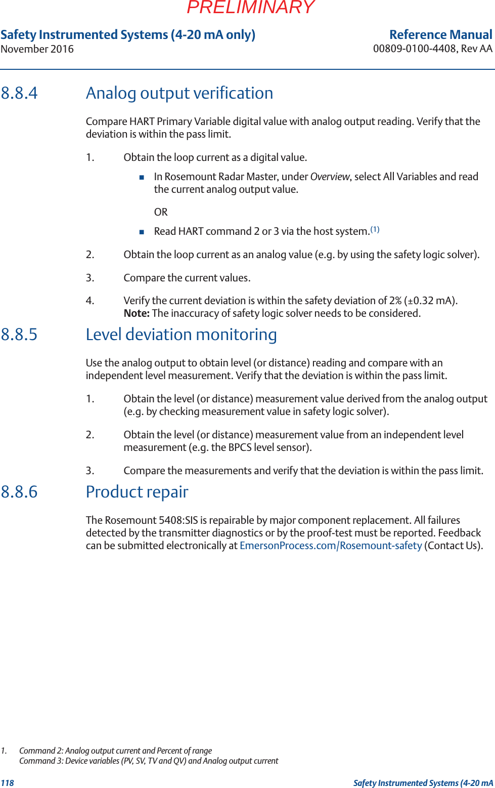
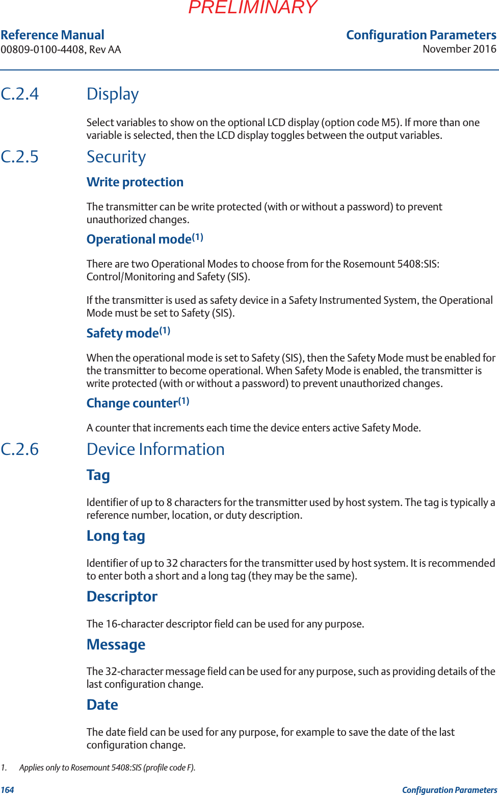
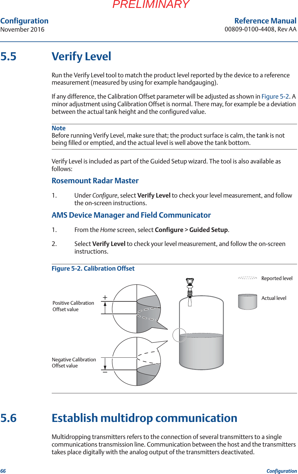
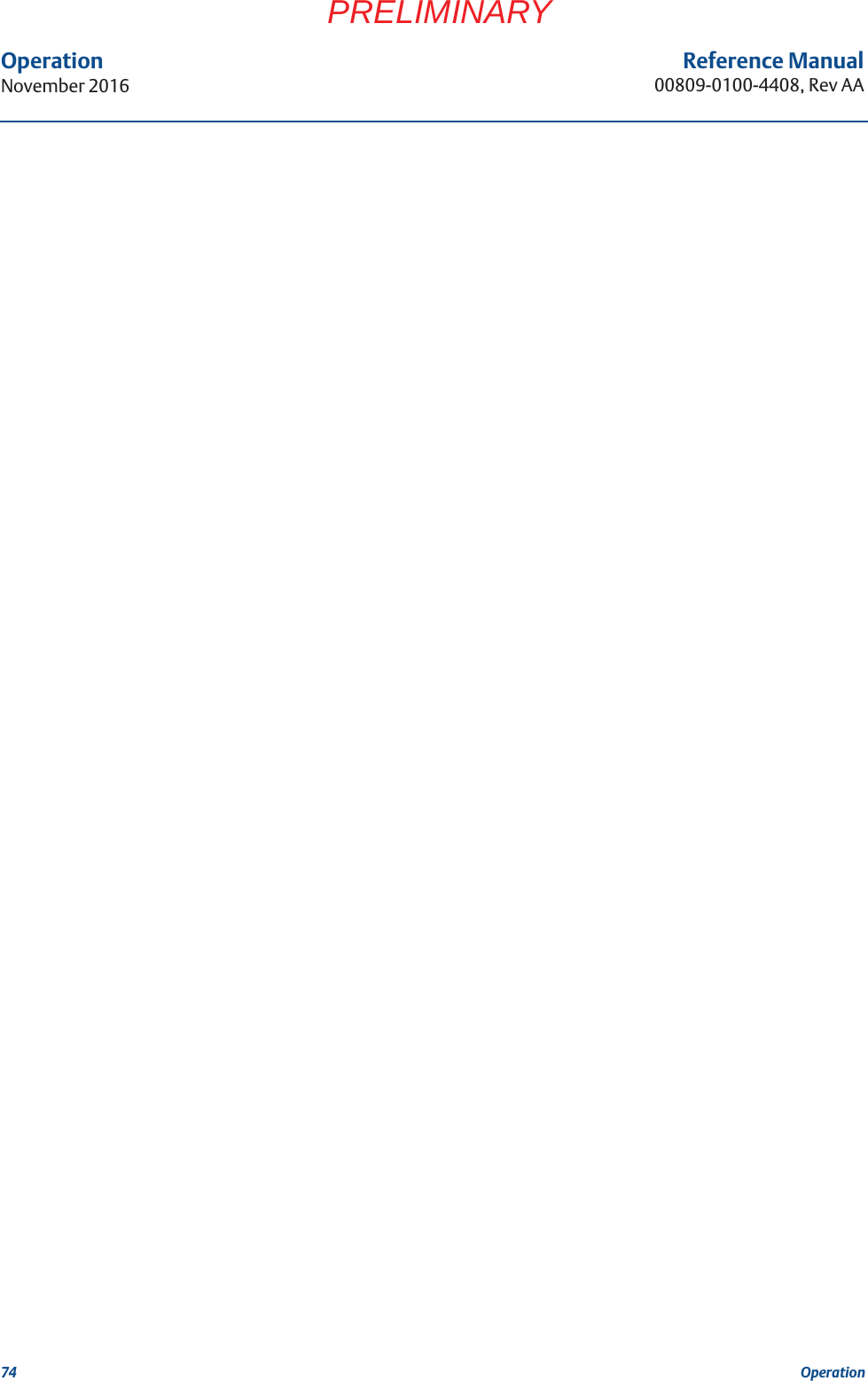
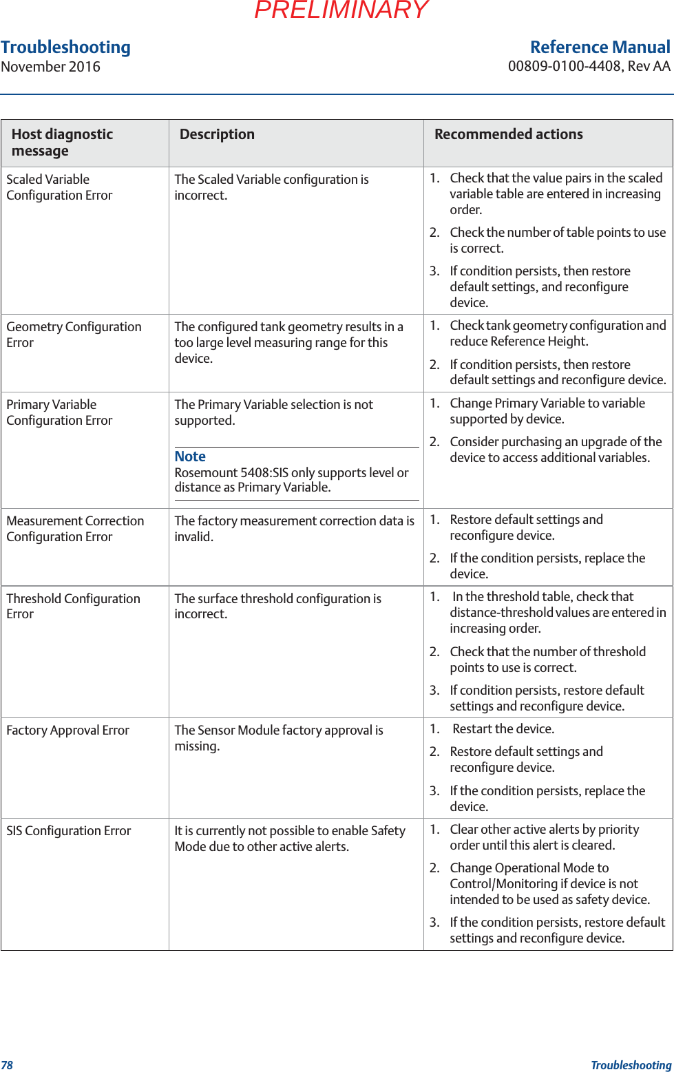
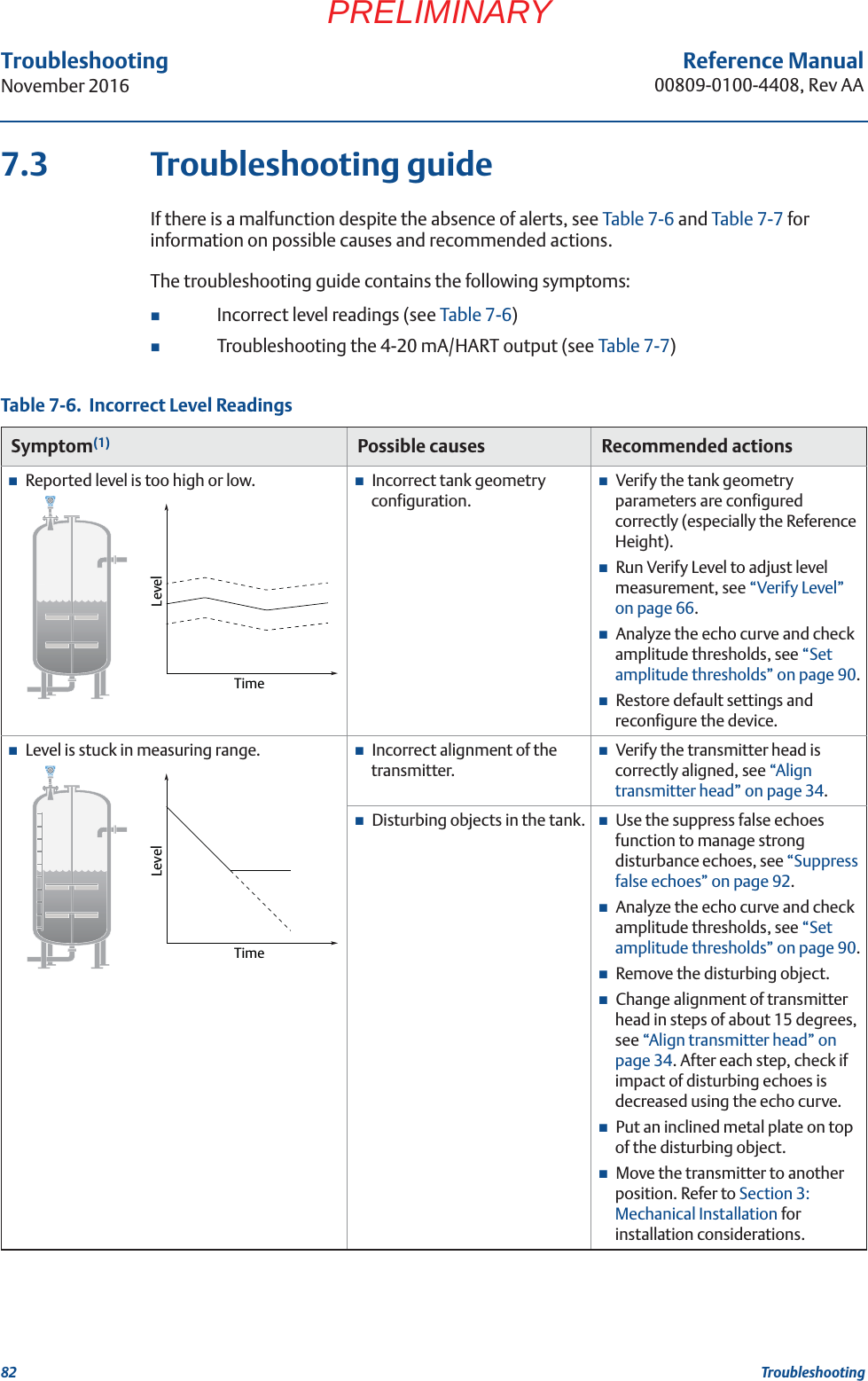
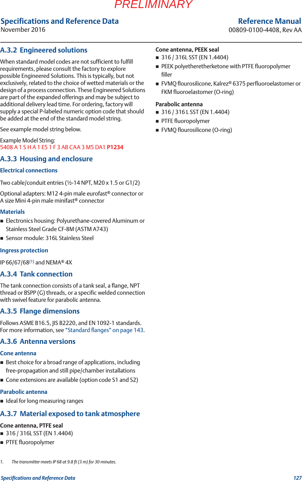
![121Specifications and Reference DataSpecifications and Reference DataNovember 2016Reference Manual00809-0100-4408, Rev AAPRELIMINARYAppendix A Specifications and Reference DataPerformance specifications . . . . . . . . . . . . . . . . . . . . . . . . . . . . . . . . . . . . . . . . . . . . . . . . page 121Functional specifications . . . . . . . . . . . . . . . . . . . . . . . . . . . . . . . . . . . . . . . . . . . . . . . . . . page 122Physical specifications . . . . . . . . . . . . . . . . . . . . . . . . . . . . . . . . . . . . . . . . . . . . . . . . . . . . page 126Ordering information . . . . . . . . . . . . . . . . . . . . . . . . . . . . . . . . . . . . . . . . . . . . . . . . . . . . . page 129Dimensional drawings . . . . . . . . . . . . . . . . . . . . . . . . . . . . . . . . . . . . . . . . . . . . . . . . . . . . page 140A.1 Performance specificationsA.1.1 GeneralReference conditionsMeasurement target: Metal plate, no disturbing objectsTemperature: 68 to 86 °F (20 to 30 °C)Ambient pressure: 14 to 15 psi (960 to1060 mbar)Relative humidity: 25-75%Instrument accuracy (under reference conditions)(1)± 0.08 in. (2 mm)Repeatability±0.04 in. (±1 mm)ResolutionTBDAmbient temperature effectTBDAmbient temperature hysteresisTBDVibration effectTBDProcess temperature effectTBDElectromagnetic interference effect(2)TBDSensor update rateTBDMaximum level rateTBDA.1.2 Measuring rangeMaximum measuring range(3)Rosemount 5408: 130 ft (40 m)Rosemount 5408:SIS: 82 ft (25 m)Blind zonesThe measuring range is limited by the Blind Zones at the very top and bottom of the tank. In the Blind Zones, the accuracy exceeds ±TBD in. (TBD mm), and measurements may not be possible. Measurements close to the Blind Zones will have reduced accuracy.Figure A-1. Accuracy Over Measuring Range1. Refer to the IEC 60770-1 (IEC 1292-2) standard for a definition of radar specific performance parameters and if applicable correspond-ing test procedure.2. Deviation through electromagnetic interference according to EN 61326.3. Note that a combination of adverse process conditions, such as heavy turbulence, foam and condensation, together with products with poor reflection may affect the measuring range.[PLACEHOLDER]](https://usermanual.wiki/Rosemount-Tank-Radar/5408T.manual-part2/User-Guide-3271963-Page-72.png)
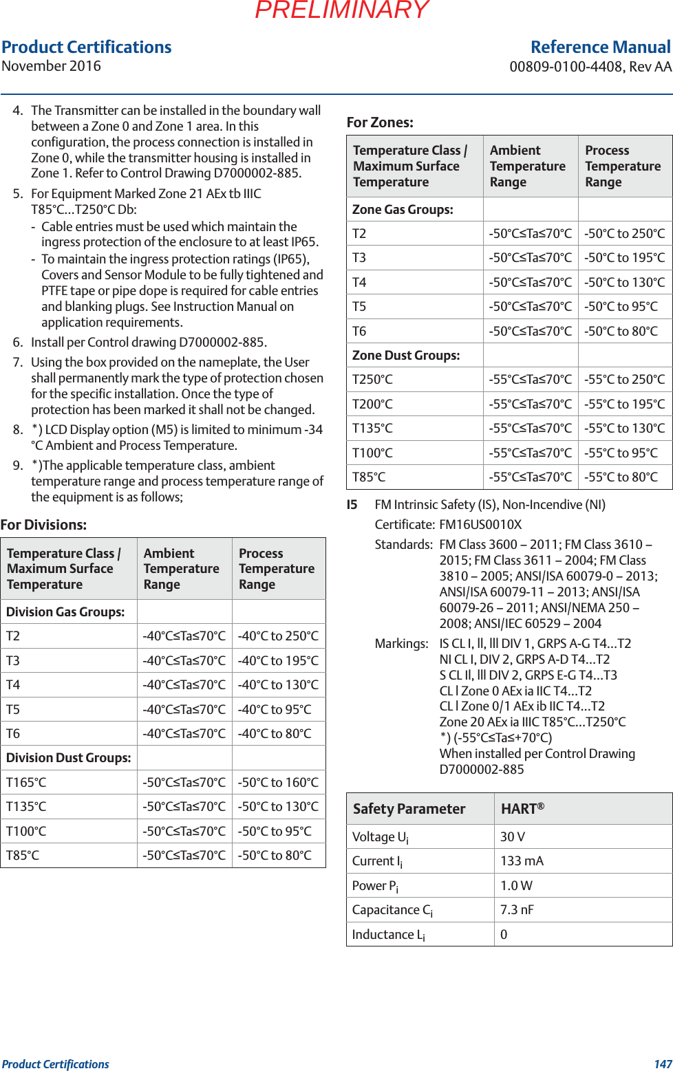
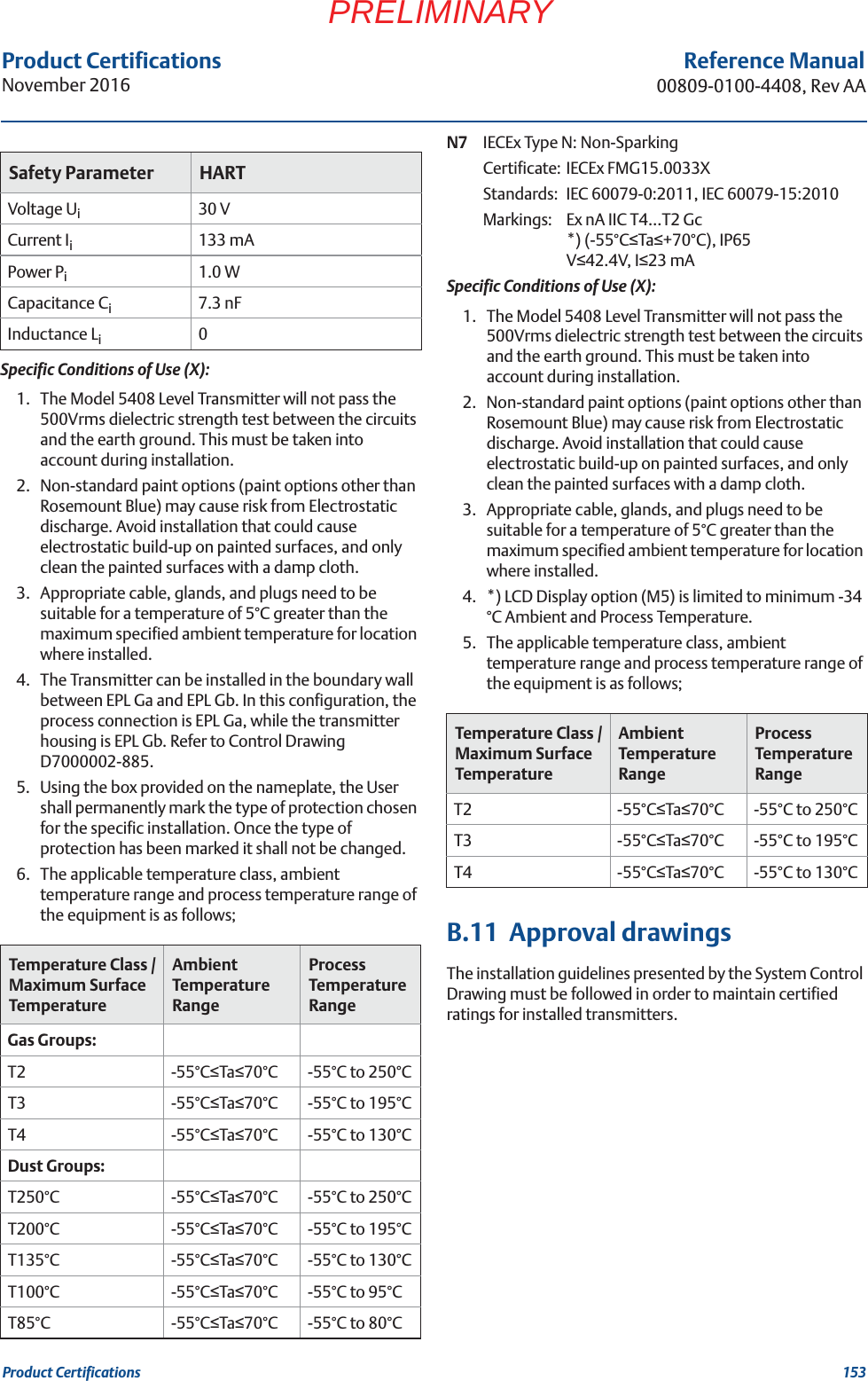
![Product CertificationsNovember 2016Reference Manual 00809-0100-4408, Rev AA146 Product CertificationsPRELIMINARY3) The installation of the LPR/TLPR device shall be done by trained installers in strict compliance with the manufacturer’s instructions.4) The use of this device is on a “no-interference, no-protection” basis. That is, the user shall accept operations of high-powered radar in the same frequency band which may interfere with or damage this device. However, devices found to interfere with primary licensing operations will be required to be removed at the user’s expense.5) Devices operating under TLPR conditions (i.e. not operating in “Open Air” Mode) shall be installed and operated in a completely enclosed container to prevent RF emissions, which can otherwise interfere with aeronautical navigation. Le présent appareil est conforme aux CNR d'Industrie Canada applicables aux appareils radio exempts de licence. L'exploitation est autorisée aux conditions suivantes: 1) l'appareil ne doit pas produire de brouillage. 2) l'utilisateur de l'appareil doit accepter tout brouillage radioélectrique subi, même si le brouillage est susceptible d'en compromettre le fonctionnement.3) L’installation d’un dispositif LPR ou TLPR doit être effectuée par des installateurs qualifiés, en pleine conformité avec les instructions du fabricant.4) Ce dispositif ne peut être exploité qu'en régime de non-brouillage et de non-protection, c'est-à-dire que l'utilisateur doit accepter que des radars de haute puissance de la même bande de fréquences puissent brouiller ce dispositif ou même l'endommager. D'autre part, les capteurs de niveau qui perturbent une exploitation autorisée par licence de fonctionnement principal doivent être enlevés aux frais de leur utilisateur.5) Un dispositif visé comme TLPR (“Open Air”) doit être installé et exploité dans un réservoir entièrement fermé afin de prévenir les rayonnements RF qui pourraient autrement perturber la navigation aéronautique.Certificate: 2827A-5408L (for LPR)2827A-5408T (for TLPR)B.5 Radio Equipment Directive (RED) 2014/53/EUThis device complies with ETSI EN 302 372 (TLPR), ETSI EN 302 729 (LPR) and EN 62479.For the receiver test that covers the influence of an interferer signal to the device, the performance criterion has at least the following level of performance according to ETSI TS 103 361 [6].Performance criterion: measurement value variation ǻd over time during a distance measurementLevel of performance: ǻd +/- 2 mmLPR (Level Probing Radar), model code “OA”Install at a separation distance of >4 km from Radio Astronomy sites, unless a special authorization has been provided by the responsible National regulatory authority (a list of Radio Astronomy sites may be found at www.craf.eu).Between 4 km to 40 km around any Radio Astronomy site the LPR antenna height shall not exceed 15 m height above ground.TLPR (Tank Level Probing Radar) The device must be installed in closed tanks. Install according to requirements in ETSI EN 302 372 (Annex E).B.6 Installing Equipment in North AmericaThe US National Electrical Code (NEC) and the Canadian Electrical Code (CEC) permit the use of Division marked equipment in Zones and Zone marked equipment in Divisions. The markings must be suitable for the area classification, gas, and temperature class. This information is clearly defined in the respective codes.B.7 USAE5 FM Explosionproof (XP), Dust-Ignitionproof (DIP)Certificate: FM16US0010XStandards: FM Class 3600 – 2011; FM Class 3615 – 2006; FM Class 3810 – 2005; ANSI/ISA 60079-0 – 2013; ANSI/ISA 60079-1 – 2009 (R2013); ANSI/ISA 60079-26 – 2011; ANSI/ISA 60079-31 – 2013; ANSI/NEMA 250 – 2008; ANSI/IEC 60529 – 2004Markings: XP CL I, DIV 1, GRPS A, B, C, D T6…T2;DIP CLII/III, DIV 1, GRPS E, F, G; T6...T3;CL I Zone 0/1 AEx db IIC T6…T2; Zone 21 AEx tb IIIC T85 °C…T250 °C *) (-40°CTa70°C); Type 4X/IP65Specific Conditions of Use (X):1. Flamepath joints are not for repair. Contact the manufacturer.2. Non-standard paint options (paint options other than Rosemount Blue) may cause risk from Electrostatic discharge. Avoid installation that could cause electrostatic build-up on painted surfaces, and only clean the painted surfaces with a damp cloth.3. Appropriate cable, glands, and plugs need to be suitable for a temperature of 5°C greater than the maximum specified ambient temperature for location where installed.](https://usermanual.wiki/Rosemount-Tank-Radar/5408T.manual-part2/User-Guide-3271963-Page-97.png)
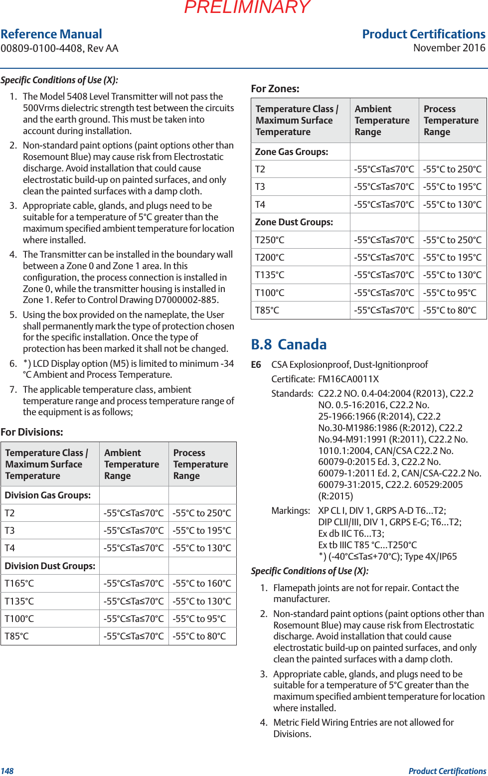
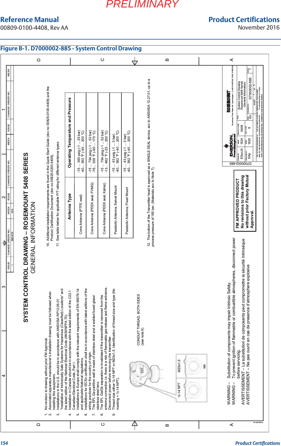
![155Product CertificationsProduct CertificationsNovember 2016Reference Manual00809-0100-4408, Rev AAPRELIMINARYSystem Control DrawingRosemount 5408 SeriesD7000002-885654081524ESa-LNEAp A32511525Ground Terminal,ExternalGround Terminal,InternalHAZARDOUS LOCATION /EXPLOSIVE ATMOSPHERE(ZONE 0/20, DIVISION 1)(ZONE 1/21, DIVISION 1)UNCLASSIFIED LOCATIONThe Entity concept allows interconnection of intrinsically safe apparatus to associatedapparatus not specifically examined in combination as a system. The approved values of max.open circuit voltage (Uo, Voc or Vt) and max. short circuit current (Io, Isc or It) and max. power(Po or Voc x Isc / 4 or Vt x It / 4), for the associated apparatus must be less than or equal to themaximum safe input voltage (Ui), maximum safe input current (Ii), and maximum safe inputpower (Pi) of the intrinsically safe apparatus. In addition, the approved max. allowableconnected capacitance (Ca or Co) of the associated apparatus must be greater than the sum ofthe interconnecting cable capacitance and the unprotected internal capacitance (Ci) of theintrinsically safe apparatus, and the approved max. Allowable connected inductance (La or Lo)of the associated apparatus must be greater than the sum of the interconnecting cableinductance and the unprotected internal inductance (Li) of the intrinsically safe apparatus.ENTITY CONCEPT APPROVALSIntrinsically safe, EPL Ga Installation[ia]BARRIERASSOCIATED APPARATUSPOWERSUPPLYD7000002-885FM APPROVED PRODUCTNo revisions to this drawingwithout prior Factory MutualApproval.(Intrinsically safe, EPL Ga installation)Ui ≤30V, Ii ≤133 mAPi ≤1W,Ci=7.3nF,Li=0uHWARNING –Substitution of components may impair Intrinsic Safety.WARNING –To prevent ignition of flammable or combustible atmospheres, disconnect powerbefore servicing.AVERTISSEMENT –La substitution de composants peut compromettre la sécurité intrinsèqueAVERTISSEMENT – Ne pas ouvrir en cas de presence d’atmosphere explosive Notes1. No revision to drawing without prior FM Approval.2. The Associated Apparatus must be FM Approved for installations in the U.S.3. The Associated Apparatus must be Canadian Approved for Installations in Canada.4. The Associated Apparatus must be ATEX Certified for Installations in Europe.5. The Associated Apparatus must be IECEx Certified for IECEx installations.6. Associated apparatus manufacturer’s installation drawing must be followed when installing this equipment.7. Installations in the U.S. should be in accordance with ANSI/ISA RP12.06.01“Installation of Intrinsically Safe Systems for Hazardous (Classified) Locations” and the latest edition of the National Electrical Code (ANSI/NFPA 70).8. Resistance between Intrinsically Safe Ground and earth ground must be less than1.0 Ohm.9. Installation in Canada should be in accordance with the latest edition of the C22.1Canadian Electrical Code, Part I.10. Installations in Europe shall comply with the relevant requirements of EN 60079-14and applicable National regulations.11. Installations for IECEx certification shall be in accordance with latest editions of thewiring practices for the country of origin.12. The Entity Concept allows interconnection of associated apparatus and intrinsicallysafe apparatus with when the following is true:Uo≤ Ui,Io≤ Ii,Po≤ Pi,Co≤Ci+Ccable;Lo≤Li+Lcable.Safe Apparatus for use in:IS Class I, DIV 1, GP A-G T4…T2CL I, Zone 0 AEx ia IIC T4…T2Zone 20 AEx ia IIIC T85°C…T250°CIS Class I, DIV 1, GP A-G T4…T2Ex ia IIC T4…T2Ex ia IIIC T85°C…T250°CII 1G Ex ia IIC T4..T2 GaII 1D Ex ia IIIC T85°C...T250°C DaEx ia IIC T4..T2 GaEx ia IIIC T85°C...T250°C DaFMUSFMcATEXIECExModel Intrinsic Entity ParametersAmbientTemperature Limits4-20mA / HART-55°C≤Ta≤+70°C-55°C≤Ta≤+70°C-55°C≤Ta≤+70°C-55°C≤Ta≤+70°CISSUED BY1234FORM REV AAADADBBCCWEEKAPPROVED BYWEEKISSUESIZEDOC. TYPEPRODUCT CODESHEETTHE COPYRIGHT/OWNERSHIP OFOFMUST NOT BE USED WITHOUT AUTHORIZATION OR BROUGHTTHIS DOCUMENT IS AND WILL REMAIN OURS. THE DOCUMENTPARTY. CONTRAVENTION WILL BE PROSECUTED. ROSEMOUNT TANK RADAR AB, SWEDENTO THE KNOWLEDGE OF A THIRDDRAWING NO.TITLERosemount Tank Radar AB, Layoutvägen 1, S-435 33 MÖLNLYCKE, SWEDENCHANGE ORDER NO. WEEKISSUECHANGE ORDER NO. WEEKISSUECHANGE ORDER NO. WEEKISSUE1SME-8739 1616](https://usermanual.wiki/Rosemount-Tank-Radar/5408T.manual-part2/User-Guide-3271963-Page-106.png)
![Product CertificationsNovember 2016Reference Manual 00809-0100-4408, Rev AA156 Product CertificationsPRELIMINARY[ib]BARRIERCHANGE ORDER NO. WEEKISSUECHANGE ORDER NO. WEEKISSUECHANGE ORDER NO. WEEKISSUESystem Control DrawingRosemount 5408 SeriesD7000002-885654081524ESa-LNEAp A33511525Ground Terminal,ExternalGround Terminal,InternalIntrinsically safe, EPL Gb installationASSOCIATED APPARATUSPOWERSUPPLYD7000002-885FM APPROVED PRODUCTNo revisions to this drawingwithout prior Factory MutualApproval.(Intrinsically safe, EPL Gb installation)Ui ≤30V, Ii ≤133 mAPi ≤1W, Ci = 7.3 nF, Li = 0 uHWARNING –Substitution of components may impair Intrinsic Safety.WARNING –To prevent ignition of flammable or combustible atmospheres, disconnect powerbefore servicing.AVERTISSEMENT –La substitution de composants peut compromettre la sécurité intrinsèqueAVERTISSEMENT – Ne pas ouvrir en cas de presence d’atmosphere explosive Notes1. No revision to drawing without prior FM Approval.2. The Associated Apparatus must be FM Approved for installations in the U.S.3. The Associated Apparatus must be Canadian Approved for Installations in Canada.4. The Associated Apparatus must be ATEX Certified for Installations in Europe.5. The Associated Apparatus must be IECEx Certified for IECEx installations.6. Associated apparatus manufacturer’s installation drawing must be followed when installing this equipment.7. Installations in the U.S. should be in accordance with ANSI/ISA RP12.06.01“Installation of Intrinsically Safe Systems for Hazardous (Classified) Locations” and the latest edition of the National Electrical Code (ANSI/NFPA 70).8. Resistance between Intrinsically Safe Ground and earth ground must be less than1.0 Ohm.9. Installation in Canada should be in accordance with the latest edition of the C22.1Canadian Electrical Code, Part I.10. Installations in Europe shall comply with the relevant requirements of EN 60079-14and applicable National regulations.11. Installations for IECEx certification shall be in accordance with latest editions of thewiring practices for the country of origin.12. The Entity Concept allows interconnection of associated apparatus and intrinsicallysafe apparatus with when the following is true:Uo≤ Ui,Io≤ Ii,Po≤ Pi,Co≤ Ci+Ccable;Lo≤Li+Lcable.13. Listed intrinsic safety parameters apply only to associated apparatus with linearoutput.Model Intrinsic Entity Parameters4-20mA / HARTHAZARDOUS LOCATION / EXPLOSIVE ATMOSPHERE(ZONE 1/21)UNCLASSIFIED LOCATIONSafe Apparatus for use in:FMUSFMcATEXIECExAmbientTemperature Limits-55°C≤Ta≤+70°C-55°C≤Ta≤+70°C-55°C≤Ta≤+70°C-55°C≤Ta≤+70°CCL I, Zone 0/1 AEx ib IIC T4…T2Zone 21 AEx ib IIIC T135°C…T250°CII 1/2G Ex ib IIC T4…T2Ga/GbII 2D Ex ib IIIC T85°C… T250°C DbEx ib IIC T4…T2Ga/GbEx ib IIIC T85°C… T250°C DbHAZARDOUS AREA(ZONE 0/21)ISSUED BY1234FORM REV AAADADBBCCWEEKAPPROVED BYWEEKISSUESIZEDOC. TYPEPRODUCT CODESHEETTHE COPYRIGHT/OWNERSHIP OFOFMUST NOT BE USED WITHOUT AUTHORIZATION OR BROUGHTTHIS DOCUMENT IS AND WILL REMAIN OURS. THE DOCUMENTPARTY. CONTRAVENTION WILL BE PROSECUTED. ROSEMOUNT TANK RADAR AB, SWEDENTO THE KNOWLEDGE OF A THIRDDRAWING NO.TITLERosemount Tank Radar AB, Layoutvägen 1, S-435 33 MÖLNLYCKE, SWEDENEx ib IIC T4…T2Ex ib IIIC T135°C…T250°C1SME-8739 1616](https://usermanual.wiki/Rosemount-Tank-Radar/5408T.manual-part2/User-Guide-3271963-Page-107.png)