Rosemount Tank Radar 5408T Rosemount 5408 Level Transmitter User Manual
Rosemount Tank Radar AB Rosemount 5408 Level Transmitter
Contents
- 1. manual_part2
- 2. manual _part1
manual_part2
50
Reference Manual
00809-0100-4408, Rev AA
Mechanical Installation
November 2016
Mechanical Installation
PRELIMINARY
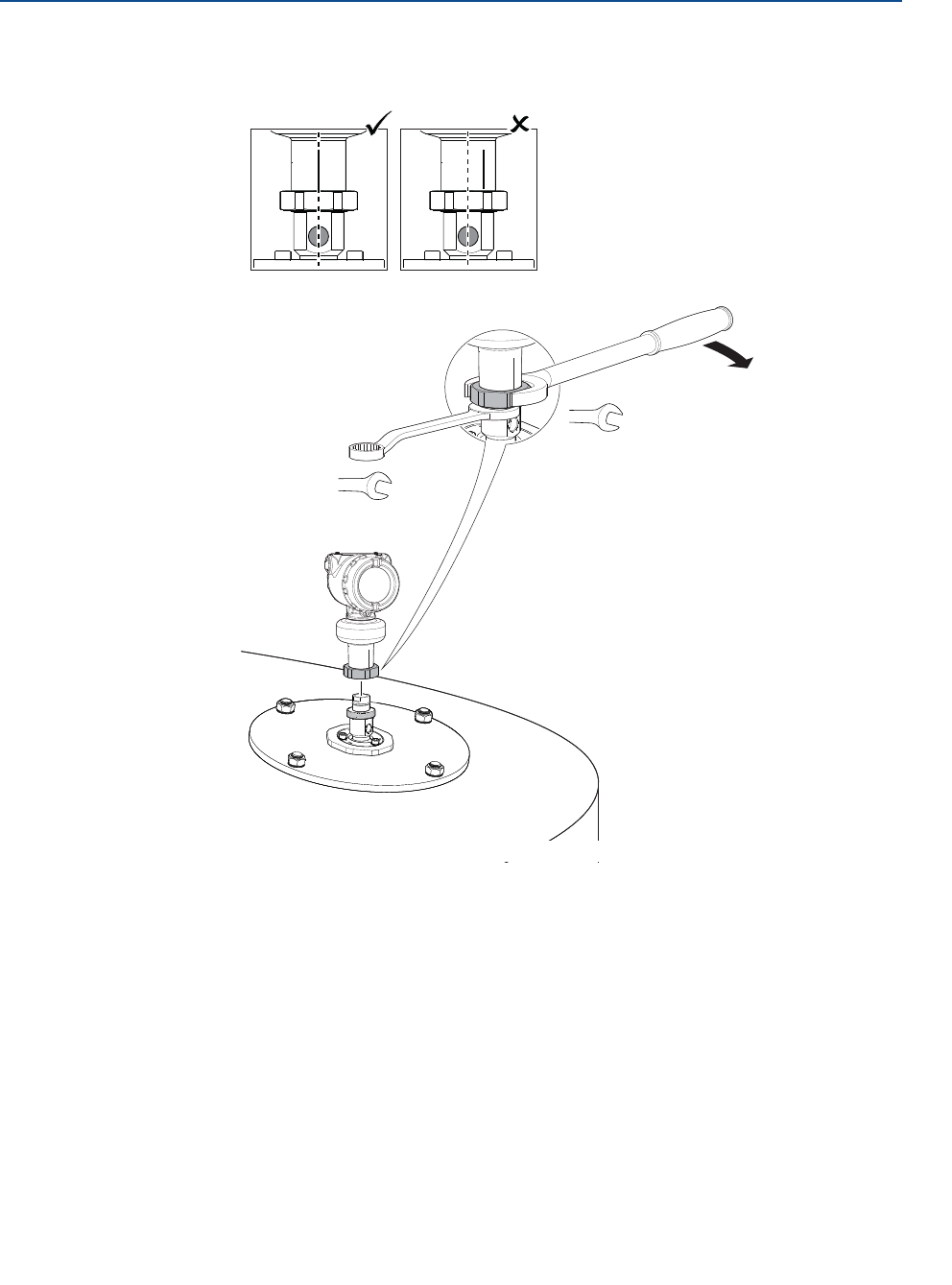
7. Mount the transmitter head.
Align the marking on sensor module with the air purge connection.
60 mm
Torque 355 in-lb (40 Nm)
36 mm
51
Reference Manual
00809-0100-4408, Rev AA
Mechanical Installation
November 2016
Mechanical Installation
PRELIMINARY
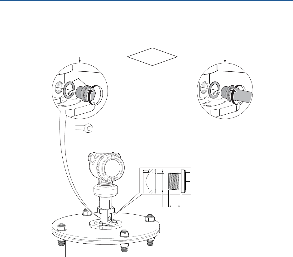
3.5.5 Connect the air purging
If air purging is not used, plug and seal the entry with the air plug kit (optional with order) or
a suitable blanking plug.
G3/8"
Air purging?No Yes
0.3-0.4 in. (8-10 mm)
(gasket excluded)
Use thread sealant or
gasket according to
your site procedures.
B
Torque 180 in-lb (20 Nm)
17 mm
52
Reference Manual
00809-0100-4408, Rev AA
Mechanical Installation
November 2016
Mechanical Installation
PRELIMINARY
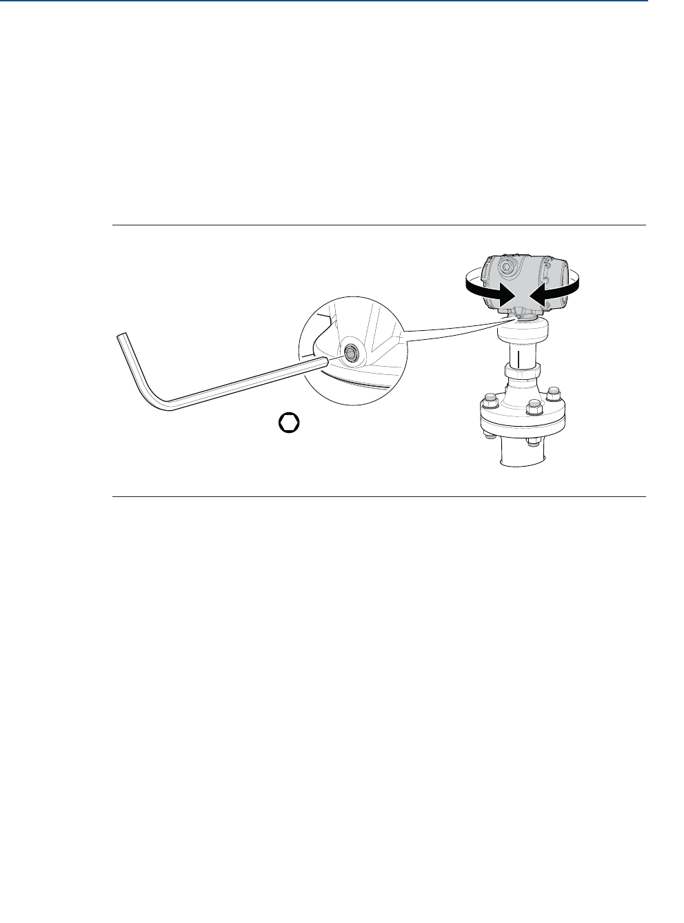
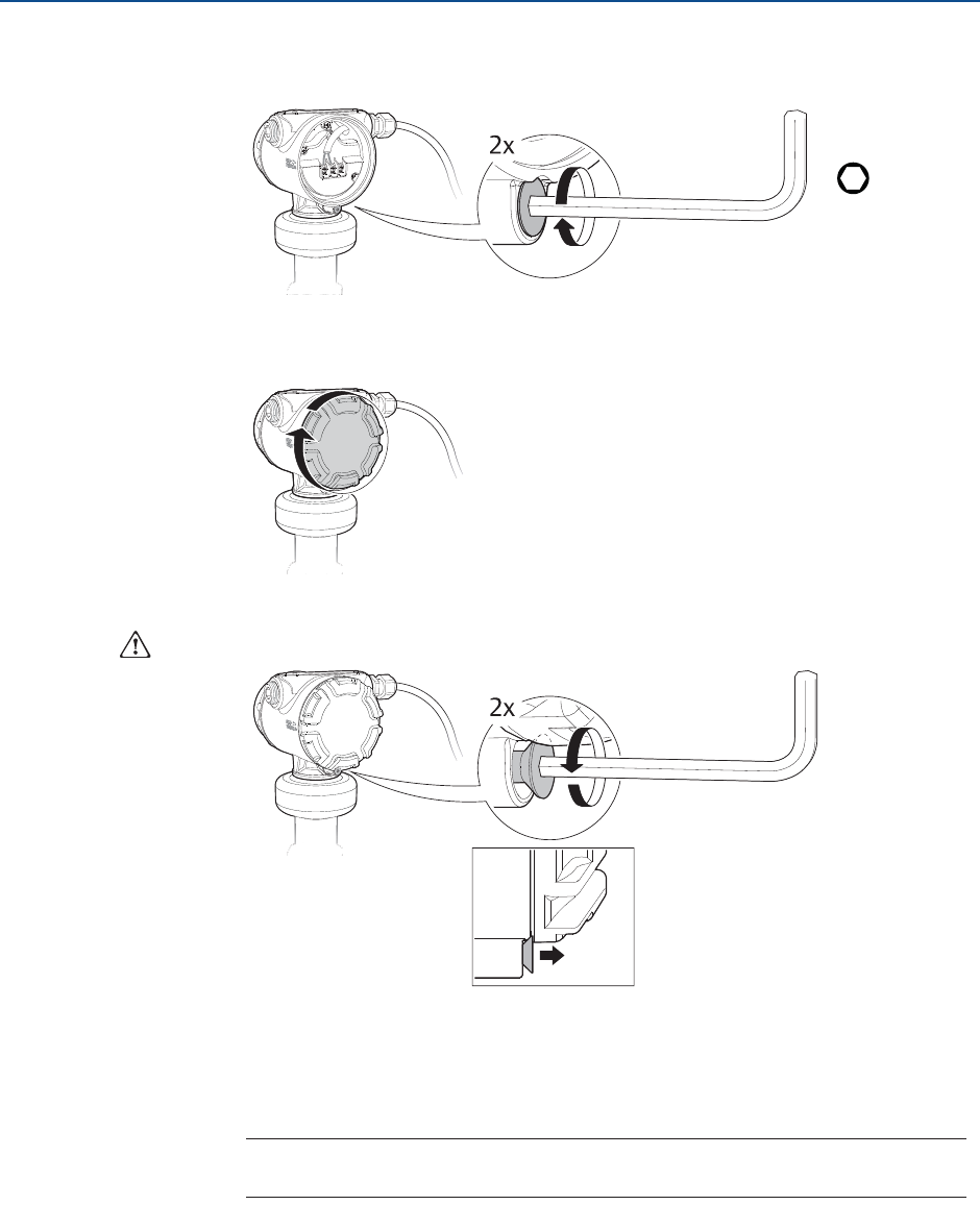
3.6 Adjust display orientation (optional)
To improve field access to wiring or to better view the optional LCD display:
1. Loosen the set screw until the transmitter housing can rotate smoothly.
2. First, rotate the housing clockwise to the desired location. If the desired location
cannot be achieved due to thread limit, rotate the housing counterclockwise to the
desired location (up to 360° from thread limit).
3. Re-tighten the set screw.
Figure 3-13. Rotate the Transmitter Housing
H3/32 in.
Torque 30 in-lb (3 Nm)

53
Reference Manual
00809-0100-4408, Rev AA
Electrical Installation
November 2016
Electrical Installation
PRELIMINARY
Section 4 Electrical Installation
Safety messages . . . . . . . . . . . . . . . . . . . . . . . . . . . . . . . . . . . . . . . . . . . . . . . . . . . . . . . . . page 53
Cable selection . . . . . . . . . . . . . . . . . . . . . . . . . . . . . . . . . . . . . . . . . . . . . . . . . . . . . . . . . . page 54
Cable gland/conduit . . . . . . . . . . . . . . . . . . . . . . . . . . . . . . . . . . . . . . . . . . . . . . . . . . . . . page 54
Power supply . . . . . . . . . . . . . . . . . . . . . . . . . . . . . . . . . . . . . . . . . . . . . . . . . . . . . . . . . . . . page 54
Hazardous areas . . . . . . . . . . . . . . . . . . . . . . . . . . . . . . . . . . . . . . . . . . . . . . . . . . . . . . . . . page 54
Wiring diagram . . . . . . . . . . . . . . . . . . . . . . . . . . . . . . . . . . . . . . . . . . . . . . . . . . . . . . . . . . page 55
Grounding . . . . . . . . . . . . . . . . . . . . . . . . . . . . . . . . . . . . . . . . . . . . . . . . . . . . . . . . . . . . . . page 55
Wiring and power up . . . . . . . . . . . . . . . . . . . . . . . . . . . . . . . . . . . . . . . . . . . . . . . . . . . . . page 57
Optional devices . . . . . . . . . . . . . . . . . . . . . . . . . . . . . . . . . . . . . . . . . . . . . . . . . . . . . . . . . page 60
4.1 Safety messages
Procedures and instructions in this section may require special precautions to ensure the
safety of the personnel performing the operation. Information that raises potential safety
issues is indicated by a warning symbol ( ). Refer to the following safety messages before
performing an operation preceded by this symbol.
Failure to follow safe installation and service guidelines could result in death or
serious injury.
Make sure only qualified personnel perform the installation.
Explosions could result in death or serious injury.
Verify that the operating environment of the transmitter is consistent with the
appropriate hazardous locations certifications.
Before connecting a Field Communicator in an explosive atmosphere, make sure
the instruments in the loop are installed in accordance with intrinsically safe or
non-incendive field wiring practices.
Do not remove the transmitter covers in explosive atmospheres when the circuit
is alive.
Both transmitter covers must be fully engaged to meet explosion-proof
requirements.
Electrical shock can result in death or serious injury.
Avoid contact with the leads and terminals. High voltage that may be present on
leads can cause electrical shock.
Make sure the main power to the transmitter is off and the lines to any other
external power source are disconnected or not powered while wiring the
transmitter.
54
Reference Manual
00809-0100-4408, Rev AA
Electrical Installation
November 2016
Electrical Installation
PRELIMINARY
4.2 Cable selection
Use 24-14 AWG wire. Twisted pairs and shielded wiring are recommended for environments
with high EMI (electromagnetic interference).
The cables must be suitable for the supply voltage and approved for use in hazardous areas,
where applicable. Two wires can be safely connected to each terminal screw.
4.3 Cable gland/conduit
For explosion-proof/flameproof installations, only use cable glands or conduit entry devices
certified explosion-proof or flameproof.
4.4 Power supply
The transmitter operates on 12-42.4 Vdc (12-30 Vdc in Intrinsically Safe installations) at the
transmitter terminals.
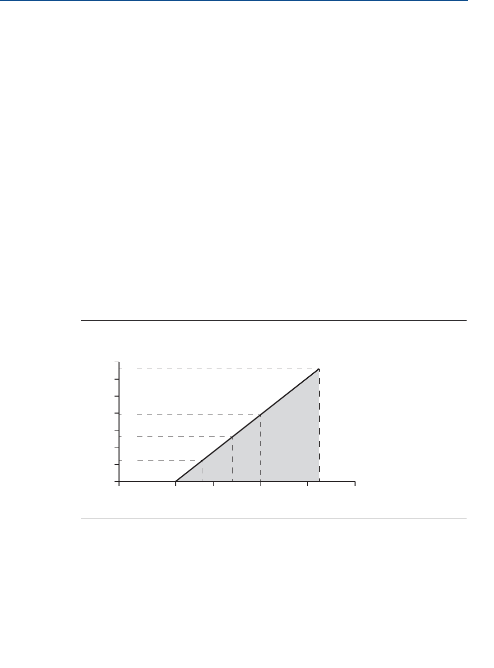
For HART communication, a minimum loop resistance of 250 : is required. Maximum loop
resistance is determined by the voltage level of the external power supply, as described by
Figure 4-1.
Figure 4-1. Load Limits
4.5 Hazardous areas
When the transmitter is installed in hazardous areas, local regulations and specifications in
applicable certificates must be observed. See Appendix B: Product Certifications for more
information.
42.4
2417.8
12
0
400
200
1000
800
600
1200
1400
20 30 40 50
521
250
782
1322
External Power Supply Voltage (Vdc)
Loop Resistance (Ohms)
Maximum Loop Resistance = 43.5 * (External Power Supply Voltage - 12)
55
Reference Manual
00809-0100-4408, Rev AA
Electrical Installation
November 2016
Electrical Installation
PRELIMINARY
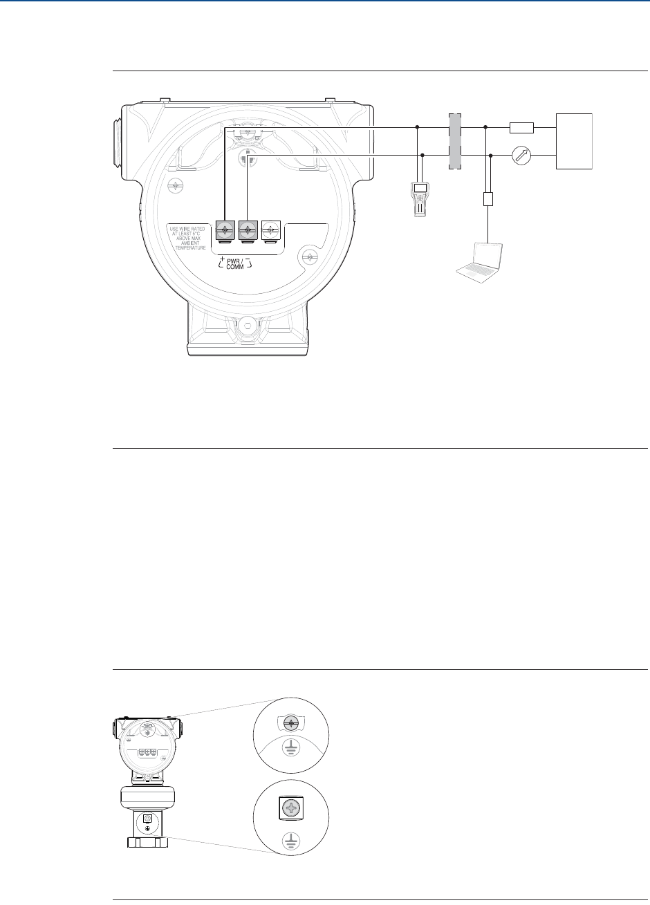
4.6 Wiring diagram
Figure 4-2. 4-20 mA/HART Communication
A. Field Communicator
B. Approved IS barrier (for Intrinsically Safe installations only)
C. HART modem
D. Load resistance (250 :
E. Current meter
4.7 Grounding
Make sure grounding is done according to national and local electrical codes. Failure to do
so may impair the protection provided by the equipment.
4.7.1 Transmitter housing
The most effective grounding method is direct connection to earth ground with minimal
impedance. There are two grounding screw connections provided (see Figure 4-3).
Figure 4-3. Ground Screws
A. Internal ground screw
B. External ground screw
A
C
BE
F
-
+
-
+
D
123
456
78
0
9
A
B
56
Reference Manual
00809-0100-4408, Rev AA
Electrical Installation
November 2016
Electrical Installation
PRELIMINARY
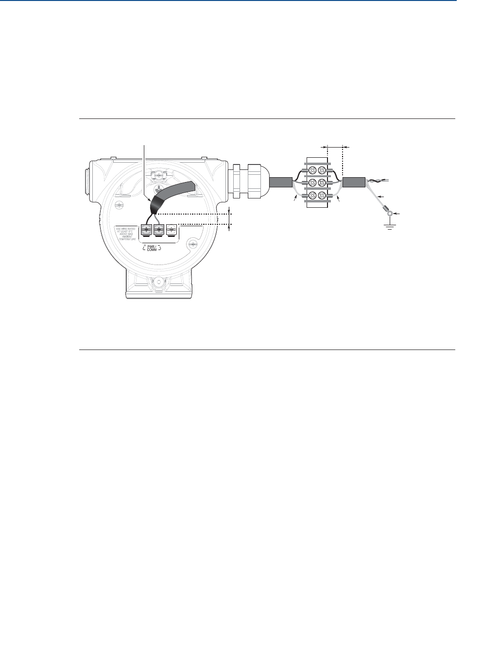
4.7.2 Signal cable shield grounding
Make sure the instrument cable shield is:
trimmed close and insulated from touching the transmitter housing.
continuously connected throughout the segment.
connected to a good earth ground at the power supply end.
Figure 4-4. Cable Shield
A. Insulate shield
B. Minimize distance
C. Trim shield and insulate
D. Connect shield back to the power supply ground
B
BA
CC
C
D
57
Reference Manual
00809-0100-4408, Rev AA
Electrical Installation
November 2016
Electrical Installation
PRELIMINARY
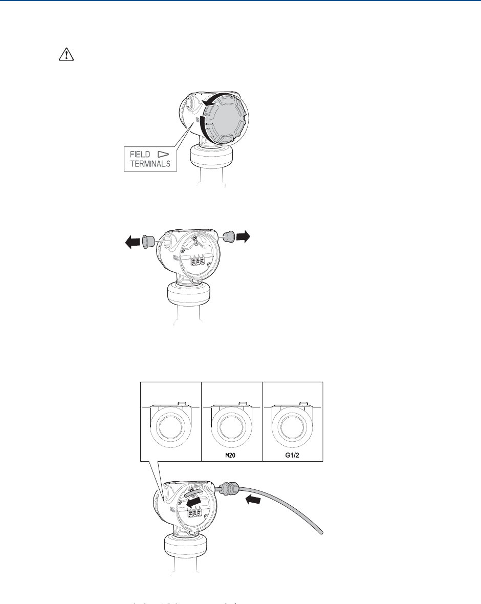
4.8 Wiring and power up
1. Verify the power supply is disconnected.
2. Remove the cover.
3. Remove the plastic plugs.
4. Pull the cable through the cable gland/conduit.(1)
1. Unless marked, the conduit/cable entries in the transmitter housing use a 1/2–14 NPT thread form.
2. G1/2 thread form is not allowed for explosion-proof/flameproof installations.
½-14 NPT M20 x 1.5
Identification of thread size and type
G1/2(2)
58
Reference Manual
00809-0100-4408, Rev AA
Electrical Installation
November 2016
Electrical Installation
PRELIMINARY
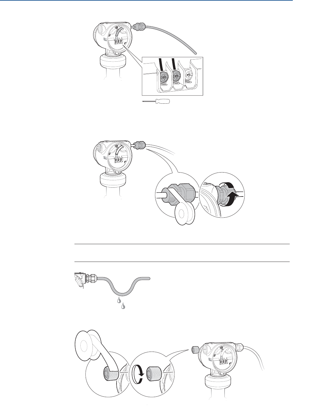
5. Connect the cable wires (see “Wiring diagram” on page 55).
6. Ensure proper grounding (see“Grounding” on page 55).
7. Tighten the cable gland.
8. Seal any unused ports with the enclosed metal plug.
Torque 7 in-lb (0.8 Nm)
PTFE tape or
other sealant
Note
Make sure to arrange the wiring with a drip loop.
PTFE tape or
other sealant
59
Reference Manual
00809-0100-4408, Rev AA
Electrical Installation
November 2016
Electrical Installation
PRELIMINARY
9. Attach and tighten the covers. Make sure the covers are fully engaged.
a. Verify the cover jam screws are completely threaded into the housing.
b. Attach and tighten the covers.
c. Turn the jam screw counterclockwise until it contacts the cover.
Required for explosion-proof/flameproof installations only.
d. Turn the jam screw an additional ½ turn counterclockwise to secure the cover.
10. Connect the power supply.
H2.5 mm
Cover jam screw
(one per side)
Note
It may take up to 15 seconds before the LCD display lights up.
60
Reference Manual
00809-0100-4408, Rev AA
Electrical Installation
November 2016
Electrical Installation
PRELIMINARY
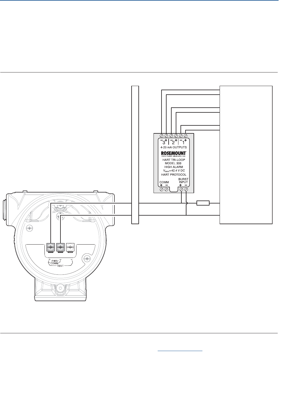
4.9 Optional devices
4.9.1 Rosemount 333 HART Tri-Loop™
The Rosemount 5408 and 5408:SIS Level Transmitters output a HART signal with four
process variables. By using the Rosemount 333 HART Tri-Loop HART-to-Analog Signal
Converter, up to three additional analog 4-20 mA outputs are provided.
Figure 4-5. Example Installation of Rosemount 333 Tri-Loop with Rosemount 5408
A. Approved IS barrier
B. DIN rail mounted Rosemount 333
C. Load resistance (250 :
D. Control room
Refer to the Rosemount 333 HART Tri-Loop Reference Manual for further information on
how to install and configure the Rosemount 333.
-
+
-
+
-
+
-
+
-
+
B
AD
C
PV
SV
TV
QV Each Tri-Loop
channel receives
power from
control room
Channel 1 must
be powered for
the Tri-Loop to
operate
Rosemount 5408
receives power
from control
room
61
Reference Manual
00809-0100-4408, Rev AA
Configuration
November 2016
Configuration
PRELIMINARY
Section 5 Configuration
Safety messages . . . . . . . . . . . . . . . . . . . . . . . . . . . . . . . . . . . . . . . . . . . . . . . . . . . . . . . . . page 61
Overview . . . . . . . . . . . . . . . . . . . . . . . . . . . . . . . . . . . . . . . . . . . . . . . . . . . . . . . . . . . . . . . page 62
Get started with your preferred configuration tool . . . . . . . . . . . . . . . . . . . . . . . . . . . page 62
Configure device using Guided Setup . . . . . . . . . . . . . . . . . . . . . . . . . . . . . . . . . . . . . . . page 65
Verify Level . . . . . . . . . . . . . . . . . . . . . . . . . . . . . . . . . . . . . . . . . . . . . . . . . . . . . . . . . . . . . . page 66
Establish multidrop communication . . . . . . . . . . . . . . . . . . . . . . . . . . . . . . . . . . . . . . . . page 66
Use with the HART Tri-Loop . . . . . . . . . . . . . . . . . . . . . . . . . . . . . . . . . . . . . . . . . . . . . . . page 67
5.1 Safety messages
Procedures and instructions in this section may require special precautions to ensure the
safety of the personnel performing the operation. Information that raises potential safety
issues is indicated by a warning symbol ( ). Refer to the following safety messages before
performing an operation preceded by this symbol.
Explosions could result in death or serious injury.
Verify that the operating environment of the transmitter is consistent with the
appropriate hazardous locations certifications.
Before connecting a Field Communicator in an explosive atmosphere, make sure
the instruments in the loop are installed in accordance with intrinsically safe or
non-incendive field wiring practices.
Do not remove the transmitter covers in explosive atmospheres when the circuit
is alive.
Both transmitter covers must be fully engaged to meet explosion-proof
requirements.
Electrical shock can result in death or serious injury.
Avoid contact with the leads and terminals. High voltage that may be present on
leads can cause electrical shock.

62
Reference Manual
00809-0100-4408, Rev AA
Configuration
November 2016
Configuration
PRELIMINARY
5.2 Overview
This chapter provides information about configuration and configuration tools. Appendix C:
Configuration Parameters provides extended information about the configuration
parameters.
5.3 Get started with your preferred configuration
tool
The Rosemount 5408 and 5408:SIS Level Transmitters can easily be configured by using:
Rosemount Radar Master (running in Instrument Inspector™)
Device Descriptor (DD) based systems, e.g. AMS™ Device Manager, 475 Field
Communicator, and DeltaV™
Field Device Integration (FDI) based systems
Rosemount Radar Master is the recommended tool for configuration.
5.3.1 Rosemount Radar Master
The Rosemount Radar Master is a user-friendly software package that includes basic
configuration options as well as advanced configuration and service functions. The
Instrument Inspector application or any FDI compliant host is needed to run Rosemount
Radar Master.
Instrument Inspector is shipped with every transmitter. See the CD installation guide for a
list of supported HART modems and system requirements.
Instrument Inspector is also available at:
http://www2.emersonprocess.com/en-US/brands/amssuite/FDI-Configura-
tion-Tool/Pages/FDI-Configuration-Tool.aspx
Get the latest FDI Package
The FDI Package is typically installed together with Instrument Inspector.
To download the latest FDI Package, visit the Emerson Process Management Device Install
Kit site at EmersonProcess.com/devicefiles.
After downloading, add the FDI Package to Instrument Inspector:
1. Start Instrument Inspector.
2. From the menu bar, select , and then select Add Device Package.
3. Browse to the downloaded FDI Package and select Open.
4. Select Add.

63
Reference Manual
00809-0100-4408, Rev AA
Configuration
November 2016
Configuration
PRELIMINARY
5.3.2 AMS Device Manager
Get the latest Device Descriptor (DD)
The Device Descriptor (DD) is a configuration tool that is developed to assist the user
through the configuration. The DD is typically installed together with AMS Device Manager.
To download the latest HART DD, visit the Emerson Process Management Device Install Kit
site at EmersonProcess.com/devicefiles
After downloading, add the DD to AMS Device Manager:
1. Close AMS Device Manager.
2. Click the Start button, and then select All Programs > AMS Device Manager >
Add Device Type.
3. Browse to the downloaded DD files and select OK.
In the Add Device Type application, select the Help button for more information on how to
complete this operation.
Configure the HART® modem interface
Before connecting to the device using a HART modem, the HART modem interface must be
configured in AMS Device Manager:
1. Close AMS Device Manager.
2. Click the Start button, and then select All Programs > AMS Device Manager >
Network Configuration.
3. Select Add.
4. In the drop down list, select HART modem and select Install.
5. Follow the on-screen instructions.
In the Network Configuration application, select the Help button for more information on
how to complete this operation.
64
Reference Manual
00809-0100-4408, Rev AA
Configuration
November 2016
Configuration
PRELIMINARY
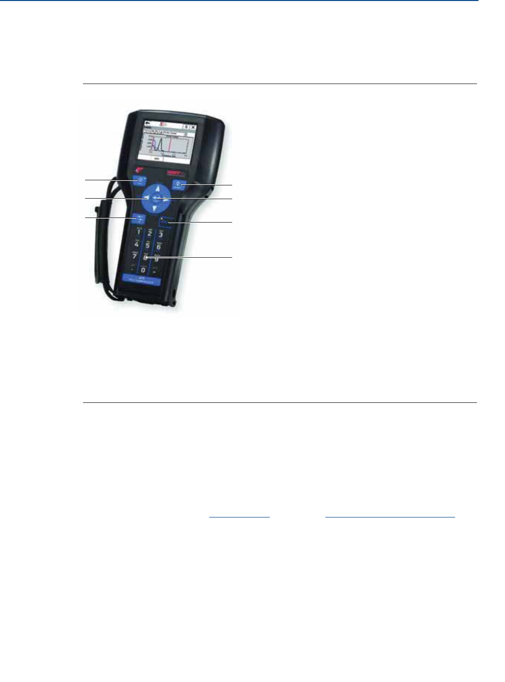
5.3.3 Field Communicator
An overview of the Field Communicator is shown in Figure 5-1. See Figure C-2 on page 161
for a menu tree diagram.
Figure 5-1. 475 Field Communicator
A. Power key
B. Navigation keys
C. Tab key
D. Backlight key
E. Enter key
F. Function key
G. Alphanumeric keypad
Get the latest Device Descriptor (DD)
If the DD is not included in your 475, then use the Easy Upgrade Utility to update the Field
Communicator with the latest DD.
For more information on how to update the device descriptors and all the capabilities, see
the 475 Field Communicator User’s Manual, available at www.fieldcommunicator.com.
F
E
D
G
A
C
B

65
Reference Manual
00809-0100-4408, Rev AA
Configuration
November 2016
Configuration
PRELIMINARY
5.4 Configure device using Guided Setup
The options available in the Guided Setup wizard include all items required for basic
operation. All basic configuration parameters are described in Appendix C: Configuration
Parameters.
Rosemount Radar Master
1. Click the Start button, and then select All Programs > Emerson Process
Management > Instrument Inspector > Instrument Inspector or double-click
the Instrument Inspector icon on the Windows™ desktop.
2. Under HART, double-click the device icon.
3. From the Overview screen, select Rosemount Radar Master.
4. Under Configure, select Guided Setup and follow the on-screen instructions.
AMS Device Manager
1. Click the Start button, and then select All Programs > AMS Device Manager >
AMS Device Manager.
2. Select View > Device Connection View.
3. In the Device Connection View, double-click the HART modem icon.
4. Double-click the device icon.
5. From the Home screen, select Configure > Guided Setup.
6. Select Basic Setup and follow the on-screen instructions.
Field Communicator
1. Turn on the Field Communicator.
2. From the Main Menu, tap the HART symbol. The Field Communicator now connects
to the device.
3. From the Home screen, select Configure > Guided Setup.
4. Select Basic Setup and follow the on-screen instructions.
66
Reference Manual
00809-0100-4408, Rev AA
Configuration
November 2016
Configuration
PRELIMINARY
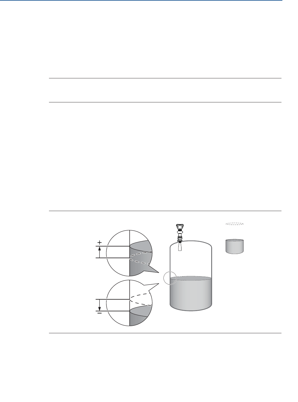
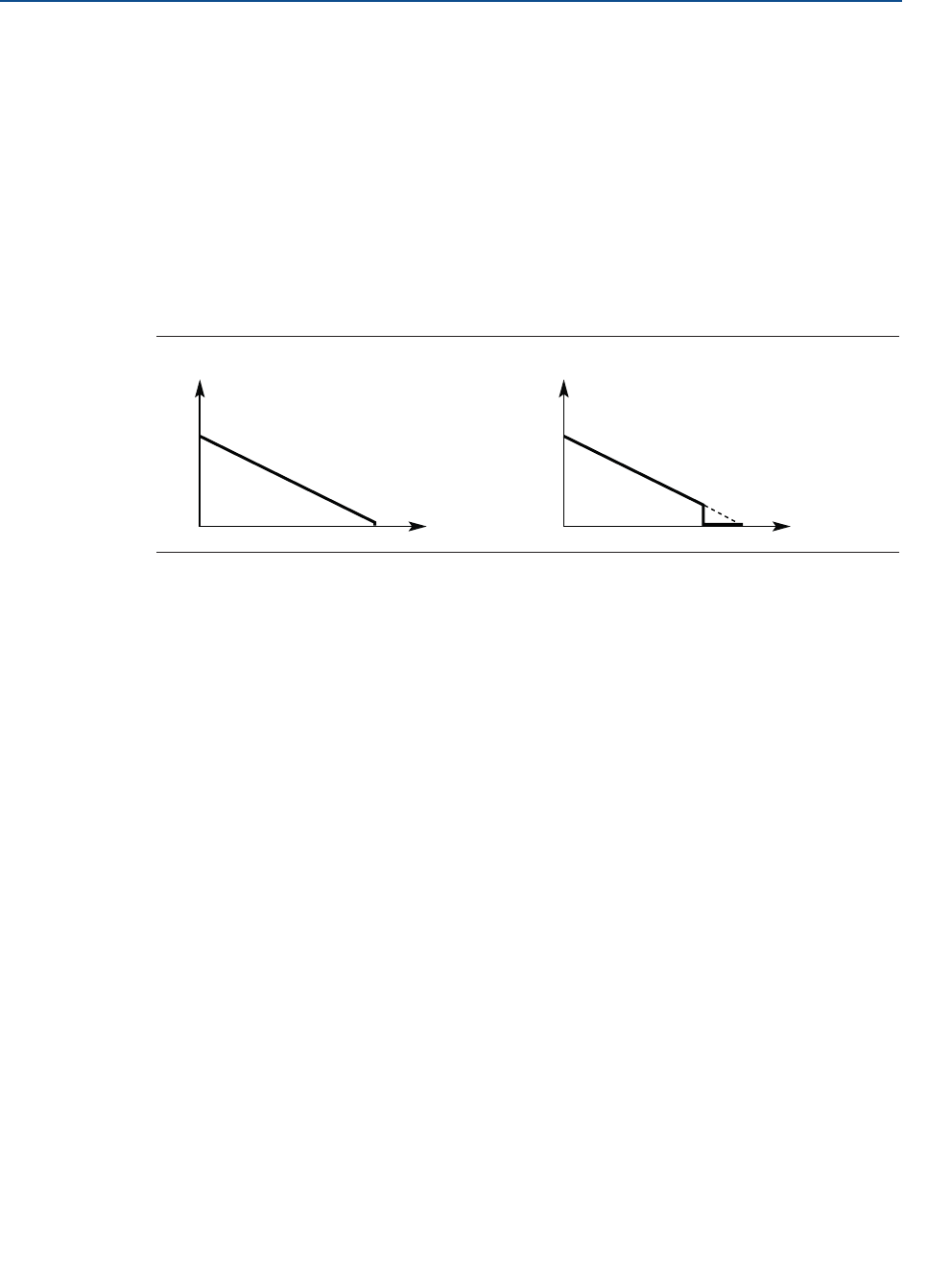
5.5 Verify Level
Run the Verify Level tool to match the product level reported by the device to a reference
measurement (measured by using for example handgauging).
If any difference, the Calibration Offset parameter will be adjusted as shown in Figure 5-2. A
minor adjustment using Calibration Offset is normal. There may, for example be a deviation
between the actual tank height and the configured value.
Note
Before running Verify Level, make sure that; the product surface is calm, the tank is not
being filled or emptied, and the actual level is well above the tank bottom.
Verify Level is included as part of the Guided Setup wizard. The tool is also available as
follows:
Rosemount Radar Master
1. Under Configure, select Verify Level to check your level measurement, and follow
the on-screen instructions.
AMS Device Manager and Field Communicator
1. From the Home screen, select Configure > Guided Setup.
2. Select Verify Level to check your level measurement, and follow the on-screen
instructions.
Figure 5-2. Calibration Offset
5.6 Establish multidrop communication
Multidropping transmitters refers to the connection of several transmitters to a single
communications transmission line. Communication between the host and the transmitters
takes place digitally with the analog output of the transmitters deactivated.
Reported level
Actual level
Positive Calibration
Offset value
Negative Calibration
Offset value

67
Reference Manual
00809-0100-4408, Rev AA
Configuration
November 2016
Configuration
PRELIMINARY
In multidrop communication, each transmitter in the loop must have a unique HART
address.
5.7 Use with the HART Tri-Loop
To prepare the transmitter for use with a Rosemount 333 HART Tri-Loop™, the transmitter
must be configured to Burst Mode and the process variable output order must be set.
AMS Device Manager and Field Communicator
1. Make sure the transmitter is properly configured.
2. If desired, change the measurement units.
From the Home screen, select Configure > Manual Setup > Device Setup >
Units.
3. Set the desired transmitter variable to use for Primary Variable (PV), Secondary
Variable (SV), Third Variable (TV), and Fourth Variable (QV).
a. From the Home screen, select Configure > Manual Setup > Device Setup >
HART.
b. Under Variable Mapping, select variables for PV, SV, TV, and QV.
4. Set the Rosemount 5408 to Burst Mode.
5. Prior to exiting the configuration, note the selected variables for SV, TV, and QV,
and the units set for each of the variables. The same configuration must be used for
the Rosemount 333.
Refer to the Rosemount 333 HART Tri-Loop Reference Manual for full information about
installing and configuring the Rosemount 333.
HART Revision 6: HART Revision 7:
a. Under Burst Mode, select On.
b. Under Burst Command, select
PV, SV, TV, QV.
a. Select Configure Burst Mode.
b. Select View/Configure Message 1.
c. Under Message 1 Broadcast, select
Wired HART Enabled.
d. Under Burst Command, select PV,
SV, TV, QV, and then select Next.
e. Under Trigger Mode, select
Continuous, and then select Next.
f. Set the Update Rate.

68
Reference Manual
00809-0100-4408, Rev AA
Configuration
November 2016
Configuration
PRELIMINARY
69
Reference Manual
00809-0100-4408, Rev AA
Operation
November 2016
Operation
PRELIMINARY
Section 6 Operation
LCD display screen messages . . . . . . . . . . . . . . . . . . . . . . . . . . . . . . . . . . . . . . . . . . . . . . . page 69
Set up the LCD display . . . . . . . . . . . . . . . . . . . . . . . . . . . . . . . . . . . . . . . . . . . . . . . . . . . . . page 70
View measurement data . . . . . . . . . . . . . . . . . . . . . . . . . . . . . . . . . . . . . . . . . . . . . . . . . . . page 71
Check device status . . . . . . . . . . . . . . . . . . . . . . . . . . . . . . . . . . . . . . . . . . . . . . . . . . . . . . . page 72
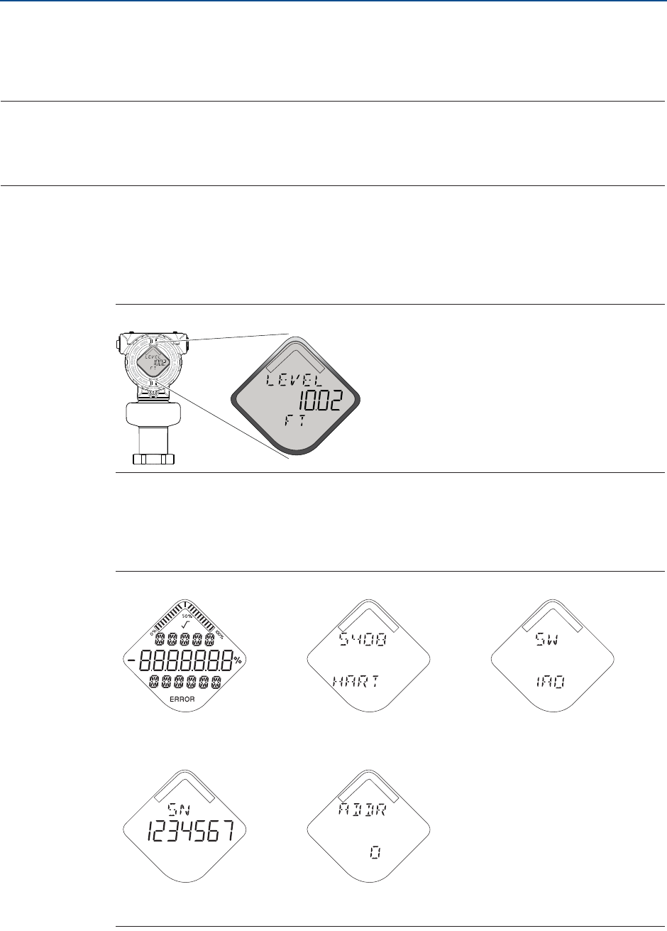
6.1 LCD display screen messages
The optional LCD display shows output variables and abbreviated diagnostic messages.
Figure 6-1. LCD Display (Option Code M5)
6.1.1 Startup screen sequence
The following screens are shown on the LCD display when the transmitter is switched on:
Figure 6-2. Startup Screen Sequence
1. All segments on 2. Device type and
communication protocol
3. Software revision
4. Serial number 5. Device HART® address

70
Reference Manual
00809-0100-4408, Rev AA
Operation
November 2016
Operation
PRELIMINARY
6.1.2 Variable screens
The Rosemount 5408 and 5408:SIS Level Transmitters can display the following variables:
Table 6-1. LCD Display Variables
6.2 Set up the LCD display
It is possible to specify the variables to be presented on the optional LCD display.
Rosemount Radar Master
1. Under Configure, select Device Setup, and then select the Display tab.
2. Select the desired variables to be displayed on the LCD display.
3. Select Save.
Parameter Presentation
on display
Description
Level LEVEL The current level measurement value.
Distance DIST Distance from the upper reference point to the
product surface.
Level Rate LR The current velocity at which the level is moving. A
positive value indicates the surface is moving up.
Signal Strength AMP The signal amplitude of the surface echo.
Volume VOLUM Volume of the product at the current level.
Electronics Temperature ITEMP The current temperature at the electronics.
Signal Quality(1)
1. Only for transmitters ordered with Smart Diagnostics Suite (option code DA1).
SIG QUALITY The quality of product surface echo signal
compared to surface threshold and noise.
Scaled Variable(1) SCALE(2)
2. Default, user selectable display text.
A variable calculated from a scaling table (as
defined by pairs of input/scaled values).
Percent of Range Primary
Variable
PV
%RANGE
A variable value expressed in percent within a
range defined by a Lower Range Value (LVR) and an
Upper Range Value (URV).
Auxiliary Percent of
Range
AUX
%RANGE
A variable value expressed in percent within a
range defined by a Lower Range Value (LVR) and an
Upper Range Value (URV).
User Defined Variable(1) USER(2) A variable associated with a selected register in the
device. Refer Table C-4 on page 175 for a list of
suitable register variables.
71
Reference Manual
00809-0100-4408, Rev AA
Operation
November 2016
Operation
PRELIMINARY
AMS Device Manager and Field Communicator
1. From the Home screen, select Configure > Manual Setup > Device Setup >
Display.
2. Select the desired variables to be displayed on the LCD display.
3. Select Send.
6.3 View measurement data
Measurement values can be viewed using Rosemount Radar Master, AMS™ Device Manager,
Field Communicator, or other communicator.
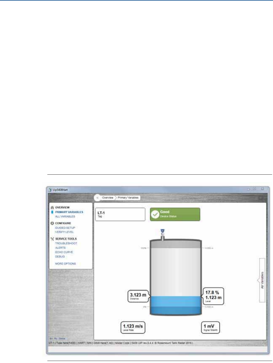
6.3.1 View current measurement values
Rosemount Radar Master
Current measurement data of the primary variables are presented on the Overview screen
together with a graphical representation of the tank (see Figure 6-3).
Select All Variables to view a complete list of all variables within the transmitter.
Figure 6-3. Overview Screen
72
Reference Manual
00809-0100-4408, Rev AA
Operation
November 2016
Operation
PRELIMINARY
AMS Device Manager and Field Communicator
Current measurement data of the primary variables are presented on the Overview screen.
To view all current measurement values, do the following:
1. From the Home Screen, select Service Tools > Variables.
2. Select Mapped Variable, Process, Device or Signal Quality.
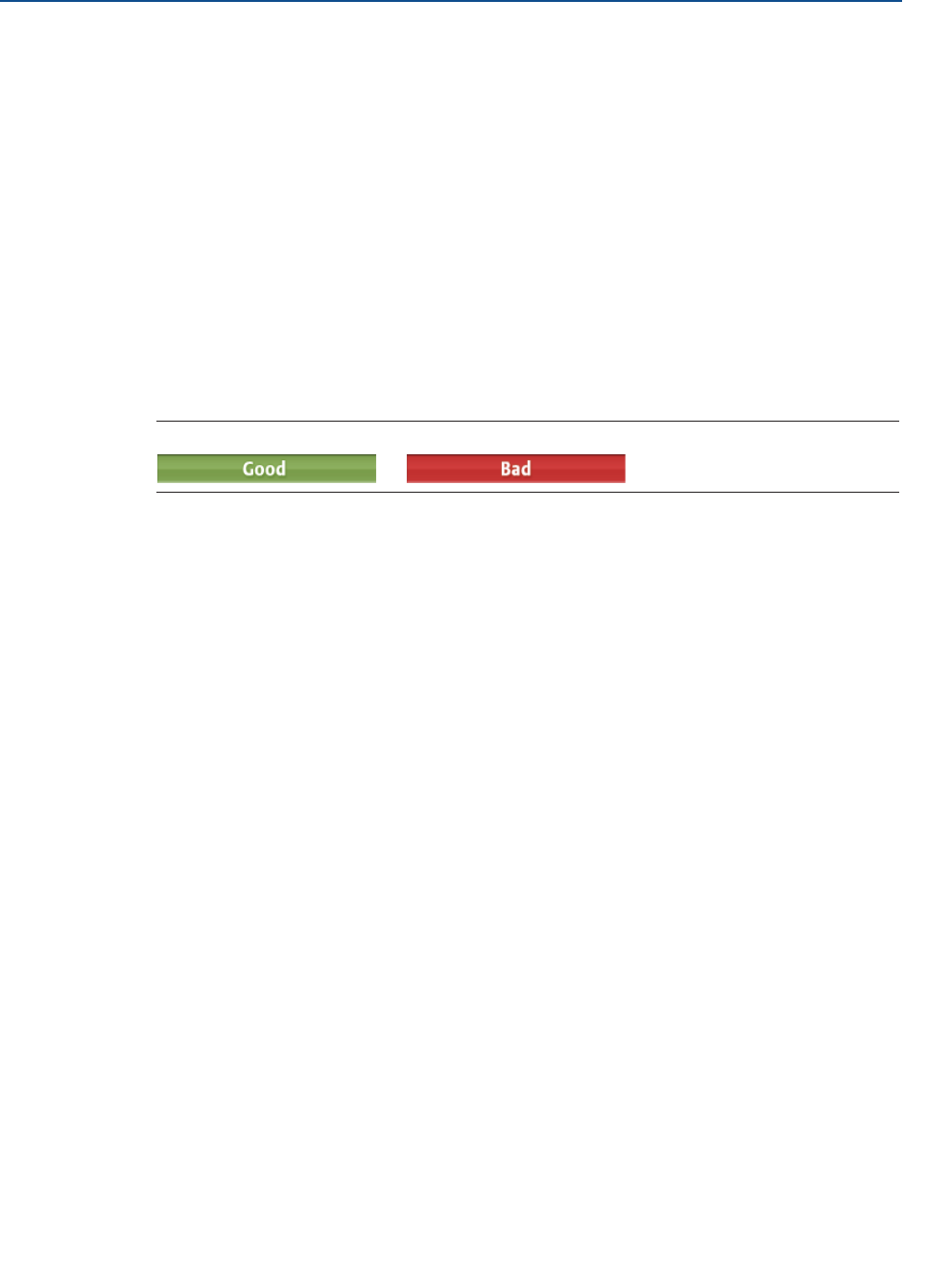
6.3.2 Interpret measurement status bars
A “Good” or “Bad” status next to a value is an indication of the reliability or integrity of the
data being received, not an indication of whether or not the value is within the configured
upper or lower ranges. A value that triggers an alert, such as a high or low temperature
indication, will change the overall status of the device, but the measurement might still be
indicated as “Good” if the reliability of the data is good.
Figure 6-4. Measurement Status Bars
6.4 Check device status
The overall device status is presented under the Overview screen in Rosemount Radar
Master, AMS Device Manager, and Field Communicator. The transmitter reports diagnostic
alerts when there is a device malfunction. For information on these alerts, see “Diagnostic
messages” on page 76.
The device can also be configured to report user defined alerts based on the measured
variables, see “Alert Setup” on page 173 for more information.
To check device status and see whether there are any active alerts reported, do one of the
following:
Go to the Overview screen to view the overall device status. If status is anything
than Good, click the button in the device status image to open a window with active
alerts. The different device status images are shown in Table 6-2.
OR
Select Service Tools > Alerts to view both active and historical alerts.
73
Reference Manual
00809-0100-4408, Rev AA
Operation
November 2016
Operation
PRELIMINARY
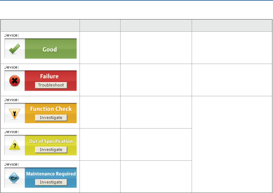
Table 6-2. Presentation of Device Status Images as per NAMUR NE 107
Device status image Category Description Action
Good No active alert. N/A
Failure At least one failure alert is
active.
Click the Troubleshoot button
to open a window with active
alerts together with
recommended actions.
Function
Check
At least one function check
alert is active.
Click the Investigate button to
open a window with active
alerts together with
recommended actions.
Out of
Specification
At least one out of
specification alert is active
(and no failure alerts).
Maintenance
Required
At least one maintenance
required alert is active (and
no failure or out of
specification alerts).

74
Reference Manual
00809-0100-4408, Rev AA
Operation
November 2016
Operation
PRELIMINARY
75
Reference Manual
00809-0100-4408, Rev AA
Troubleshooting
November 2016
Troubleshooting
PRELIMINARY
Section 7 Troubleshooting
Safety messages . . . . . . . . . . . . . . . . . . . . . . . . . . . . . . . . . . . . . . . . . . . . . . . . . . . . . . . . . page 75
Diagnostic messages . . . . . . . . . . . . . . . . . . . . . . . . . . . . . . . . . . . . . . . . . . . . . . . . . . . . . page 76
Troubleshooting guide . . . . . . . . . . . . . . . . . . . . . . . . . . . . . . . . . . . . . . . . . . . . . . . . . . . page 82
Service and troubleshooting tools . . . . . . . . . . . . . . . . . . . . . . . . . . . . . . . . . . . . . . . . . page 87
Write protect a transmitter . . . . . . . . . . . . . . . . . . . . . . . . . . . . . . . . . . . . . . . . . . . . . . . . page 98
Application challenges . . . . . . . . . . . . . . . . . . . . . . . . . . . . . . . . . . . . . . . . . . . . . . . . . . . . page 99
Service support . . . . . . . . . . . . . . . . . . . . . . . . . . . . . . . . . . . . . . . . . . . . . . . . . . . . . . . . . . page 104
7.1 Safety messages
Procedures and instructions in this section may require special precautions to ensure the
safety of the personnel performing the operation. Information that raises potential safety
issues is indicated by a warning symbol ( ). Refer to the following safety messages before
performing an operation preceded by this symbol.
Failure to follow safe installation and service guidelines could result in death or
serious injury.
Make sure only qualified personnel perform the installation.
Explosions could result in death or serious injury.
Verify that the operating environment of the transmitter is consistent with the
appropriate hazardous locations certifications.
Before connecting a Field Communicator in an explosive atmosphere, make sure
the instruments in the loop are installed in accordance with intrinsically safe or
non-incendive field wiring practices.
Do not remove the transmitter covers in explosive atmospheres when the circuit
is alive.
Both transmitter covers must be fully engaged to meet explosion-proof
requirements.
Electrical shock can result in death or serious injury.
Avoid contact with the leads and terminals. High voltage that may be present on
leads can cause electrical shock.
Make sure the main power to the transmitter is off and the lines to any other
external power source are disconnected or not powered while wiring the
transmitter.

76
Reference Manual
00809-0100-4408, Rev AA
Troubleshooting
November 2016
Troubleshooting
PRELIMINARY
7.2 Diagnostic messages
Diagnostic messages per NAMUR NE 107 are listed in Table 7-1 to Table 7-5.
Table 7-1. Status - Failed
LCD display
message
Host diagnostic
message
Description Recommended actions
ELEC
FAILUR
Electronics Failure,
Transmitter
An electronics error has occurred.
The device measurement reading is
invalid.
1. Restart the device.
2. Consider increasing Alarm Delay
parameter for intermittent conditions.
3. If the condition persists, replace the
transmitter housing.
ELEC
FAILUR
Electronics Failure,
Sensor Module
An electronics error has occurred.
The device measurement reading is
invalid.
1. Restart the device.
2. Consider increasing Alarm Delay
parameter for intermittent conditions.
3. If the condition persists, replace the
sensor module.
MEMRY
FAILUR
Device Memory
Failure
A device memory error has occurred.
The device measurement reading is
invalid.
1. Restore default settings, restart
device, and reconfigure device.
2. If the condition persists, replace the
device.
ANTEN
FAILUR
Radar Antenna
Disconnected
The device cannot detect the radar
antenna.
The device measurement reading is
invalid.
1. Check that the nut between
transmitter and process seal is
properly tightened.
2. Check that the antenna connection is
dry and clean.
3. Restart the device.
4. If the condition persists, replace the
device or the process seal with
antenna, or both.
SIGNL
FAILUR
Radar Signal Failure The received radar signal is invalid
resulting in an invalid device
measurement reading.
1. Clean the antenna.
2. Consider increasing Alarm Delay
parameter for intermittent conditions.
3. If the condition persists, replace
device.
START
FAILUR
Startup Failure Device repeatedly failed to start up
with user configuration settings.
The device measurement reading is
invalid.
1. Check supply voltage is within range
and restart device.
2. Restore default settings, restart
device, and reconfigure device.
3. If the condition persists, replace the
device.

77
Reference Manual
00809-0100-4408, Rev AA
Troubleshooting
November 2016
Troubleshooting
PRELIMINARY
Table 7-2. Configuration Error Details
SW
ERROR
Software Error The software in the device
encountered a problem and stopped
running which may cause an invalid
measurement reading.
In some cases, problems may be
caused by temporary environmental
conditions (e.g. electromagnetic
interferences) and not observed
again.
1. Restart the device.
2. Restore default settings and
reconfigure the device.
3. If the condition persists, replace the
device.
MEAS
FAILUR
Level Measurement
Lost
No valid level reading. Reasons may be
multiple:
No valid surface echo peak in the
measuring range.
Incorrect device configuration.
1. Analyze the Echo Curve at time of loss
for reason and check device
configuration, especially thresholds.
2. Check device physical installation (for
instance antenna contamination).
3. Consider increasing Alarm Delay
parameter for intermittent conditions.
4. Restart the device.
5. Restore default settings and
reconfigure the device.
6. If the condition persists, replace the
device.
CONFG
ERROR
Configuration Error The device has detected a
configuration error. Reasons may be
multiple (see Table 7-2 for details).
1. Click the Details button for more
information.
2. Correct the parameter causing the
error.
Host diagnostic
message
Description Recommended actions
Volume Configuration Error The volume cannot be calculated correctly
with the current configuration.
1. If strapping table is used, check that
level-volume values are entered in
increasing order.
2. If strapping table is used, check that
number of strapping points to use is
correct.
3. If tank dimensions are used for volume,
check that geometry size measures are
correct.
4. If condition persists, restore default
settings and reconfigure device.
LCD display
message
Host diagnostic
message
Description Recommended actions

78
Reference Manual
00809-0100-4408, Rev AA
Troubleshooting
November 2016
Troubleshooting
PRELIMINARY
Scaled Variable
Configuration Error
The Scaled Variable configuration is
incorrect.
1. Check that the value pairs in the scaled
variable table are entered in increasing
order.
2. Check the number of table points to use
is correct.
3. If condition persists, then restore
default settings, and reconfigure
device.
Geometry Configuration
Error
The configured tank geometry results in a
too large level measuring range for this
device.
1. Check tank geometry configuration and
reduce Reference Height.
2. If condition persists, then restore
default settings and reconfigure device.
Primary Variable
Configuration Error
The Primary Variable selection is not
supported.
Note
Rosemount 5408:SIS only supports level or
distance as Primary Variable.
1. Change Primary Variable to variable
supported by device.
2. Consider purchasing an upgrade of the
device to access additional variables.
Measurement Correction
Configuration Error
The factory measurement correction data is
invalid.
1. Restore default settings and
reconfigure device.
2. If the condition persists, replace the
device.
Threshold Configuration
Error
The surface threshold configuration is
incorrect.
1. In the threshold table, check that
distance-threshold values are entered in
increasing order.
2. Check that the number of threshold
points to use is correct.
3. If condition persists, restore default
settings and reconfigure device.
Factory Approval Error The Sensor Module factory approval is
missing.
1. Restart the device.
2. Restore default settings and
reconfigure device.
3. If the condition persists, replace the
device.
SIS Configuration Error It is currently not possible to enable Safety
Mode due to other active alerts.
1. Clear other active alerts by priority
order until this alert is cleared.
2. Change Operational Mode to
Control/Monitoring if device is not
intended to be used as safety device.
3. If the condition persists, restore default
settings and reconfigure device.
Host diagnostic
message
Description Recommended actions

79
Reference Manual
00809-0100-4408, Rev AA
Troubleshooting
November 2016
Troubleshooting
PRELIMINARY
Function Not Supported Functionality in the device is enabled, but
not supported by this device.
Additional features may be enabled by
purchasing an upgrade of the device.
1. Check that selections for variables (e.g.
Primary Variable) are supported by this
device.
2. Turn off functionality not supported by
this device.
3. Consider purchasing an upgrade of the
device to access additional variables
and functionality.
4. If condition persists, restore default
settings and reconfigure device.
Antenna Type Configuration
Error
The configured Antenna Type is not
supported by the device.
1. Check configuration of Antenna Type.
2. Make sure the configured antenna type
matches the physical antenna for the
device.
Factory Calibration Error The factory calibration in the device is
missing.
1. Replace the device.
Analog Out Span
Configuration Error
The span for the configured analog out
range is too small.
1. Increase analog out span by adjusting
Upper or Lower Range Value.
Analog Out Calibration Error Analog output calibration failed. 1. Try calibrating the analog output again.
2. If the condition persists, replace the
device.
SIS Multidrop Error HART® multidrop mode is not supported for
safety (SIS) devices. Only 4-20 mA output is
supported for safety devices.
1. Disable multidrop mode.
2. Change Operational Mode to
Control/Monitoring if device is not
intended to be used as safety device.
3. If the condition persists, restore default
settings and reconfigure device.
Factory Approval Error The Transmitter factory approval is missing. 1. Restart the device.
2. Restore default settings and
reconfigure device.
3. If the condition persists, replace the
device.
Engineering Unit
Configuration Error
One of the configured engineering units is
not supported by the device.
1. Check unit configuration.
2. If condition persists, restore default
settings and reconfigure device.
Burst Mode Configuration
Error
The burst mode configuration is incorrect. 1. Check configuration of burst mode.
2. If condition persists, restore default
settings and reconfigure device.
Start Code Configuration
Error
The start code to enable options in the
device is invalid.
Note
Start codes are unique for individual devices
and cannot be copied from one device to
another.
1. Enter a valid start code for this device
using the Upgrade function.
2. If condition persists, contact your local
Emerson representative to get a valid
start code.
Host diagnostic
message
Description Recommended actions

80
Reference Manual
00809-0100-4408, Rev AA
Troubleshooting
November 2016
Troubleshooting
PRELIMINARY
Table 7-3. Status - Function Check
Table 7-4. Status - Out of Specification
Table 7-5. Status - Maintenance Required
LCD display
message
Host diagnostic
message
Description Recommended actions
SAFE
DISBLD
Safety Mode Not
Activated
Safety Mode is disabled and device is
in alarm mode.
This device is configured for use in
Safety Instrumented Systems (SIS)
which requires Safety Mode to be
enabled.
1. Change Safety Mode to Enabled for
use in SIS application.
2. Change Operational Mode to
Control/Monitoring if device is not
intended to be used as safety device.
SIMUL
ACTIVE
Simulation/Test
Active
The device is in simulation or test
mode and is not reporting actual
information.
1. If this behavior is not desired, stop
simulation or test mode.
2. If the condition persists, restart device.
LCD display
message
Host diagnostic
message
Description Recommended actions
TEMP
LIMITS
Electronics
Temperature Out of
Limits
The temperature of the electronics
board has exceeded the transmitter’s
operating range.
1. Verify ambient temperature is within
the operating range.
2. Remote mount the transmitter away
from the process and environmental
conditions.
LCD display
message
Host diagnostic
message
Description Recommended actions
SUPLY
LOW
Supply Voltage Low The supply voltage is low and may
affect device operation.
1. Check supply voltage is within range.
LOW
SIG Q
Low Signal Quality The Signal Quality is below the
defined alert limit.
1. Take action based on your intended
use of this alert.
2. Clean the antenna.
3. If no actions were necessary, consider
to change the limit.
HIGH
ALERT
High User Defined
Alert
The user defined variable is above the
defined limit.
1. Bring the system to a safe state.
2. Verify that the process variable is
within specified limits.
3. Reconfirm the user defined alarm
limit.
4. If not needed, disable this alert.

81
Reference Manual
00809-0100-4408, Rev AA
Troubleshooting
November 2016
Troubleshooting
PRELIMINARY
LOW
ALERT
Low User Defined
Alert
The user defined variable is below the
defined limit.
1. Bring the system to a safe state.
2. Verify that the process variable is
within specified limits.
3. Reconfirm the user defined alarm
limit.
4. If not needed, disable this alert.
VAR
OUTRNG
Linearized Variable
Out of Range
The level measurement is outside the
configured range for volume or scaled
variable, or both.
Accuracy of volume/scaled variable
measurement may be degraded.
1. If volume strapping table is used,
make sure level values within
operating range are included.
2. If scaled variable table is used, make
sure input variable values within
operating range are included.
DC
DEGRAD
Dielectric Constant
Estimation
Degraded
The dielectric constant estimation is
degraded.
Accuracy of level measurement may
be degraded.
1. Check configuration of Bottom
Product Dielectric Constant.
2. Check configuration of Reference
Height and Bottom Offset.
3. If not needed, disable Tank Bottom
Projection.
LCD display
message
Host diagnostic
message
Description Recommended actions
82
Reference Manual
00809-0100-4408, Rev AA
Troubleshooting
November 2016
Troubleshooting
PRELIMINARY
7.3 Troubleshooting guide
If there is a malfunction despite the absence of alerts, see Table 7-6 and Table 7-7 for
information on possible causes and recommended actions.
The troubleshooting guide contains the following symptoms:
Incorrect level readings (see Table 7-6)
Troubleshooting the 4-20 mA/HART output (see Table 7-7)
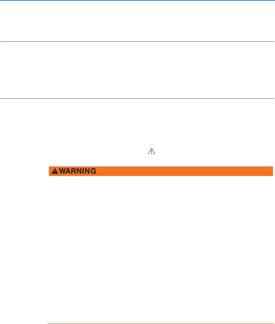
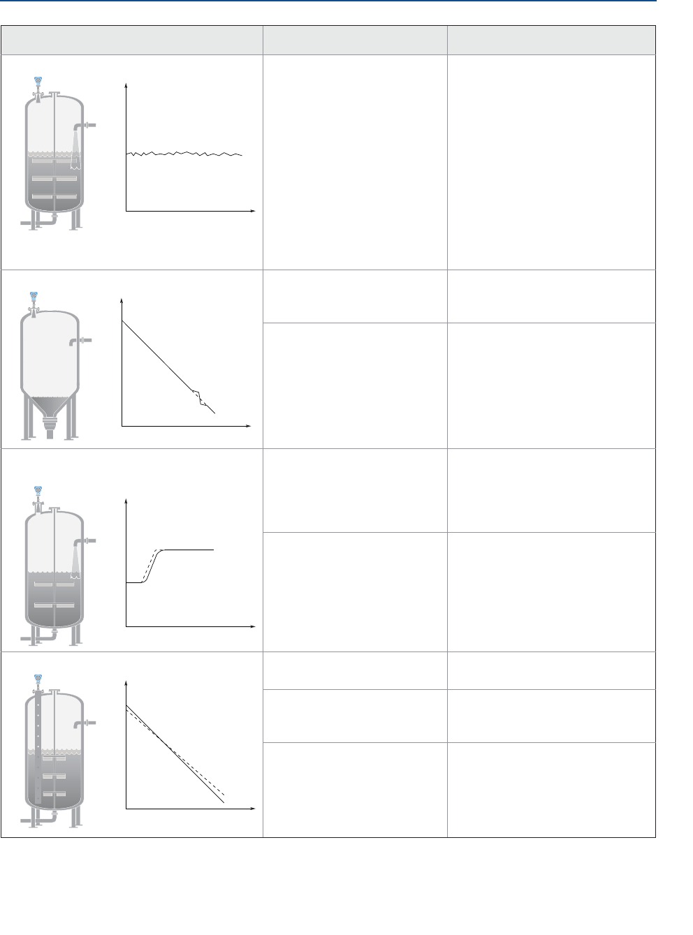
Table 7-6. Incorrect Level Readings
Symptom(1) Possible causes Recommended actions
Reported level is too high or low. Incorrect tank geometry
configuration.
Verify the tank geometry
parameters are configured
correctly (especially the Reference
Height).
Run Verify Level to adjust level
measurement, see “Verify Level”
on page 66.
Analyze the echo curve and check
amplitude thresholds, see “Set
amplitude thresholds” on page 90.
Restore default settings and
reconfigure the device.
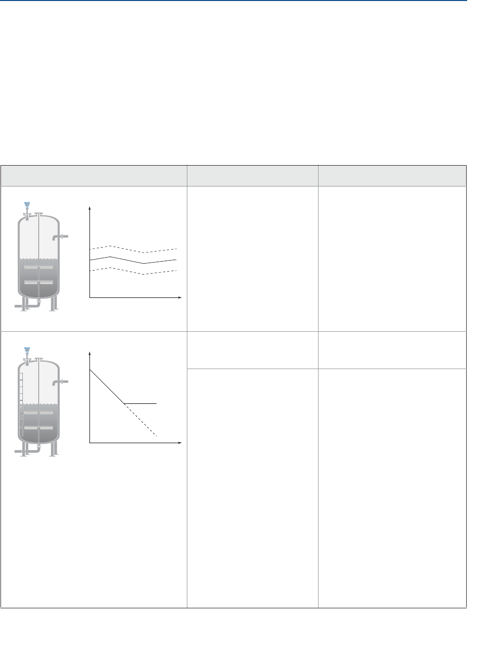
Level is stuck in measuring range. Incorrect alignment of the
transmitter.
Verify the transmitter head is
correctly aligned, see “Align
transmitter head” on page 34.
Disturbing objects in the tank. Use the suppress false echoes
function to manage strong
disturbance echoes, see “Suppress
false echoes” on page 92.
Analyze the echo curve and check
amplitude thresholds, see “Set
amplitude thresholds” on page 90.
Remove the disturbing object.
Change alignment of transmitter
head in steps of about 15 degrees,
see “Align transmitter head” on
page 34. After each step, check if
impact of disturbing echoes is
decreased using the echo curve.
Put an inclined metal plate on top
of the disturbing object.
Move the transmitter to another
position. Refer to Section 3:
Mechanical Installation for
installation considerations.
Level
Time
Level
Time
83
Reference Manual
00809-0100-4408, Rev AA
Troubleshooting
November 2016
Troubleshooting
PRELIMINARY
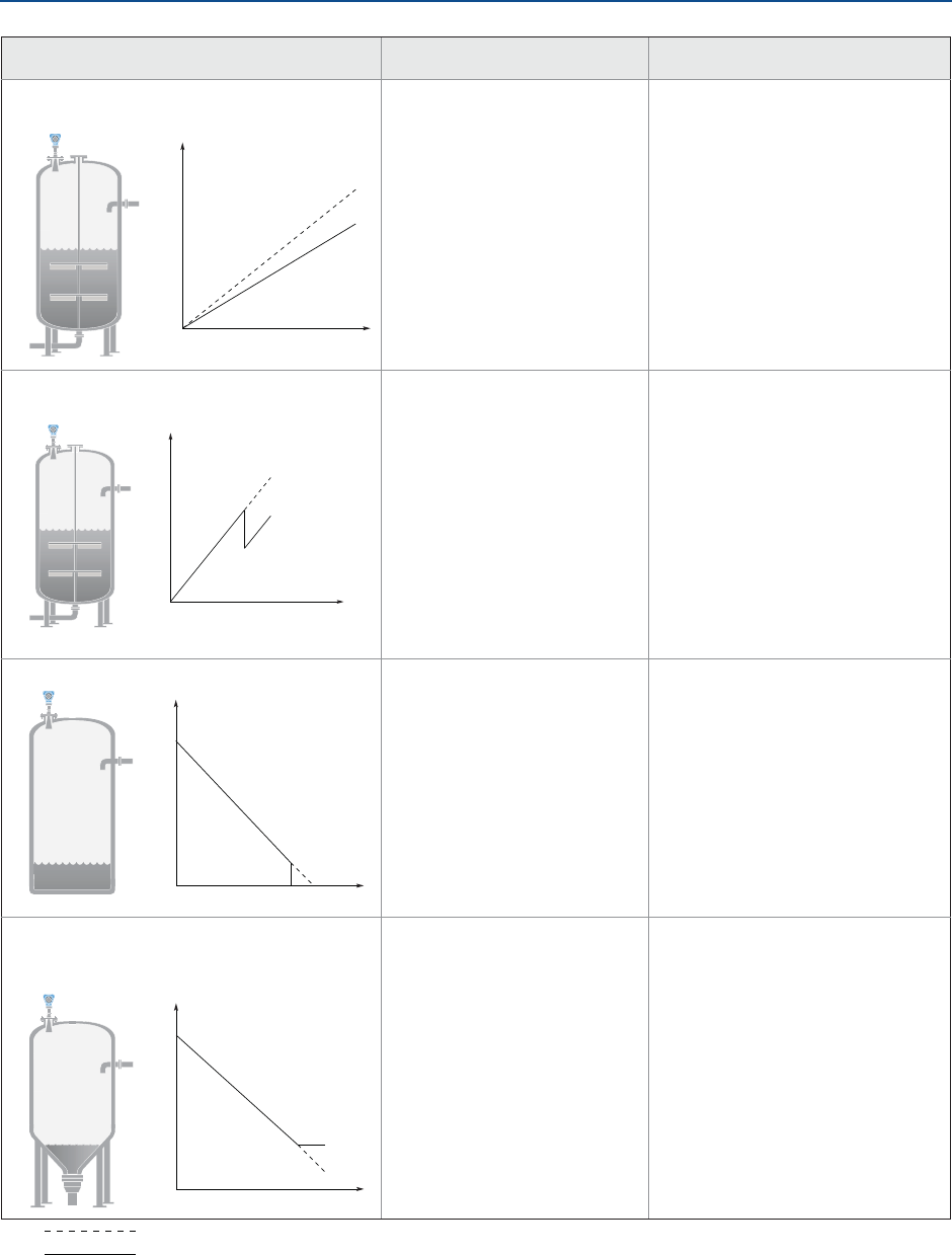
Level is stuck in full. Disturbing objects near the
antenna.
Use the suppress false echoes
function to manage strong
disturbance echoes, see “Suppress
false echoes” on page 92.
Analyze the echo curve and check
amplitude thresholds, see “Set
amplitude thresholds” on page 90.
Increase the Upper Null Zone, see
“Handling disturbances at top of
tank” on page 99.
Remove the disturbing object.
Move the transmitter to another
position. Refer to Section 3:
Mechanical Installation for
installation considerations.
Product build-up on the
antenna.
Clean the antenna.
Use transmitter with air purging
connection.
Cone antenna does not
extend below the nozzle.
Use the extended cone antenna.
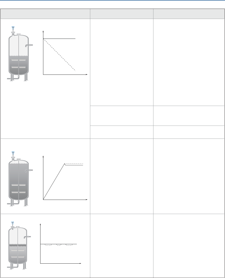
Level value drops to a lower value when
product surface is close to antenna.
Product surface is within the
Upper Null Zone and a
disturbance echo is
interpreted as the product
surface.
Check the setting of the Upper
Null Zone, see “Upper null zone”
on page 174.
Measured value jumps to a lower value. Multiple products in the tank,
e.g. thin oil layer on top of
water that is sometimes
detected, sometimes not.
Set Double Surface Handling to
Track Upper Surface or Track Lower
Surface, see “Double surface
handling” on page 177.
Symptom(1) Possible causes Recommended actions
Level
Time
Level
Time
Level
Time
84
Reference Manual
00809-0100-4408, Rev AA
Troubleshooting
November 2016
Troubleshooting
PRELIMINARY
Measured level fluctuates. Excessive foaming or
turbulence.
Under turbulent conditions with
low level rates, consider increasing
the Damping value, see “Damping
value” on page 162.
Enable the Foam parameter or
Turbulent Sur face parameter, or
both. See “Process conditions” on
page 171.
If two surfaces are seen in foamy
applications, set Double Surface
Handling to Track Lower Surface.
See “Double surface handling” on
page 177.
Measured level is occasionally unstable. May be caused by an empty
tank with the amplitude
threshold set too low.
Analyze the echo curve and check
amplitude thresholds, see “Set
amplitude thresholds” on page 90.
The product surface is close to
a suppressed false echo.
If possible, remove the disturbing
object.
Measured level lags during rapid level
changes.
Damping value too high. If there is a problem with lag
during rapid level changes,
consider decreasing the Damping
value, see “Damping value” on
page 162.
Maximum Level Rate value too
low.
Verify Maximum Level Rate
configuration.
Incorrect level when using still pipe. Device is not configured for
still pipe measurement.
Enable pipe measurement, see
“Mounting type” on page 167.
Incorrect Pipe Inner Diameter
configuration.
Verify the configured Pipe Inner
Diameter matches the physical
inner diameter.
Ghost echo problems below
the product surface.
Enable the Track First Echo
function, see “Handling ghost
echoes in still pipes” on page 102.
Symptom(1) Possible causes Recommended actions
Level
Time
Level
Time
Level
Time
Level
Time
85
Reference Manual
00809-0100-4408, Rev AA
Troubleshooting
November 2016
Troubleshooting
PRELIMINARY
Measured level is correct at 0% (4 mA) but
incorrect at 100% (20 mA).
Upper Range Value is not set
correctly.
Check that the Upper Range Value
matches the 100% (20 mA) level in
the tank.
Incorrect level when the product surface is
above the 50% level.
Strong double bounce echo
that is interpreted as the
product surface.
Enable the Double Bounce
Handling function, see “Handling
strong double bounce echoes” on
page 103.
Measured value drops to zero level. Transmitter has locked on a
strong tank bottom echo.
Verify the Reference Height is
configured correctly.
Enable the Tank Bottom Projection
function, see “Use tank bottom
projection” on page 100.
Enable the Bottom echo visible
when tank is empty parameter, see
“Enable bottom echo visible when
tank is empty” on page 100.
When the product surface is near the sloped
tank bottom, the transmitter enters alarm
mode.
Reduction of projected
surface area close to sloping
tank bottom.
Verify the tank geometry
parameters are configured
correctly (especially the Reference
Height and Bottom Offset).
If measurement in this region is
not crucial, increase the Empty
Tank Detection Area, see “Empty
tank detection area” on page 176.
Verify the Bottom echo visible when
tank is empty parameter is
disabled, see “Bottom echo visible
when tank is empty” on page 176.
1. = actual level
= reported level
Symptom(1) Possible causes Recommended actions
Level
Time
Level
Time
Level
Time
Level
Time

86
Reference Manual
00809-0100-4408, Rev AA
Troubleshooting
November 2016
Troubleshooting
PRELIMINARY
Table 7-7. Troubleshooting the 4-20 mA/HART Output
Symptom Recommended actions
Transmitter milliamp reading is zero. Verify power is applied to signal terminals.
Verify power supply voltage is adequate at signal terminals, see
“Power supply” on page 54.
Verify transmitter and power supply are properly grounded.
Transmitter milliamp reading is too low or high. Verify level.
Check the settings of the 4-20 mA range values, see“Upper/lower
range value” on page 163.
Verify output is not in alarm condition.
Check that power wires are connected to the correct signal
terminals.
Perform Calibrate Analog Out, see “Calibrate analog out” on
page 95.
Milliamp reading is erratic. Verify power supply voltage is adequate at signal terminals, see
“Power supply” on page 54.
Check for external electrical interference.
Verify transmitter is properly grounded.
Verify shield for twisted pair is only grounded at the power supply
end.
Under turbulent conditions with low level rates, consider
increasing the Damping value.
Transmitter will not respond to changes in level. Verify level is between the 4 and 20 mA set points.
Verify output is not in alarm condition.
Verify transmitter is not in loop test or simulation mode.
No HART communication. Verify power supply voltage is adequate at signal terminals, see
“Power supply” on page 54.
Check load resistance (250 ohms minimum).
Check if transmitter is at an alternate HART address.
Check current analog output value to verify that transmitter
hardware works.
87
Reference Manual
00809-0100-4408, Rev AA
Troubleshooting
November 2016
Troubleshooting
PRELIMINARY
7.4 Service and troubleshooting tools
This section briefly describes tools and functions in the Rosemount Radar Master, AMS
Device Manager, and Field Communicator, which may be useful for service and
troubleshooting of the Rosemount 5408 and 5408:SIS Level Transmitters.
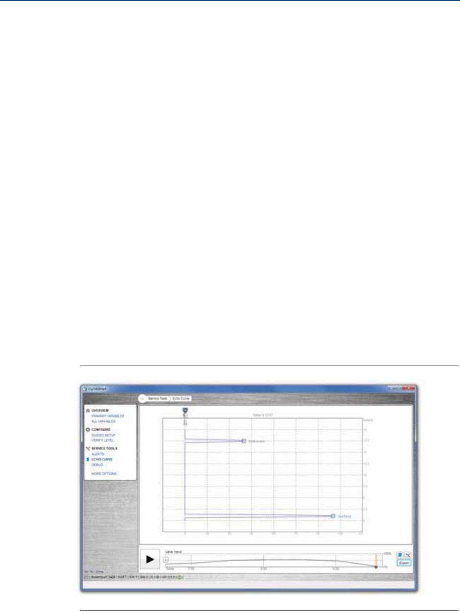
7.4.1 Use the echo curve function
The Rosemount Radar Master software includes functions for viewing and recording single
instances or movies of the echo curve. The echo curve represents the tank, as seen by the
radar transmitter. Each peak corresponds to a strong reflection of the radar signal.
When connected to Rosemount Radar Master, past measurement records and echo curves
including the 10 highest peaks, as well as the 50 last event alerts are automatically
transferred from the transmitter’s internal memory to the hard drive on your local
computer. Past measurement records are then available the next time you connect to the
transmitter using the level trend timeline (see Figure 7-1).
Measurement problems can be understood by studying the position and amplitude of the
different peaks. Additionally, the recorded echo curves give insight into unexpected and
intermittent measurement behaviors, for instance, at the time of the triggered alert.
Read the echo curve
To read the echo curve in Rosemount Radar Master:
1. Under Service Tools, select Echo Curve.
2. Select Play.
Figure 7-1. Echo Curve
[PLACEHOLDER]
88
Reference Manual
00809-0100-4408, Rev AA
Troubleshooting
November 2016
Troubleshooting
PRELIMINARY
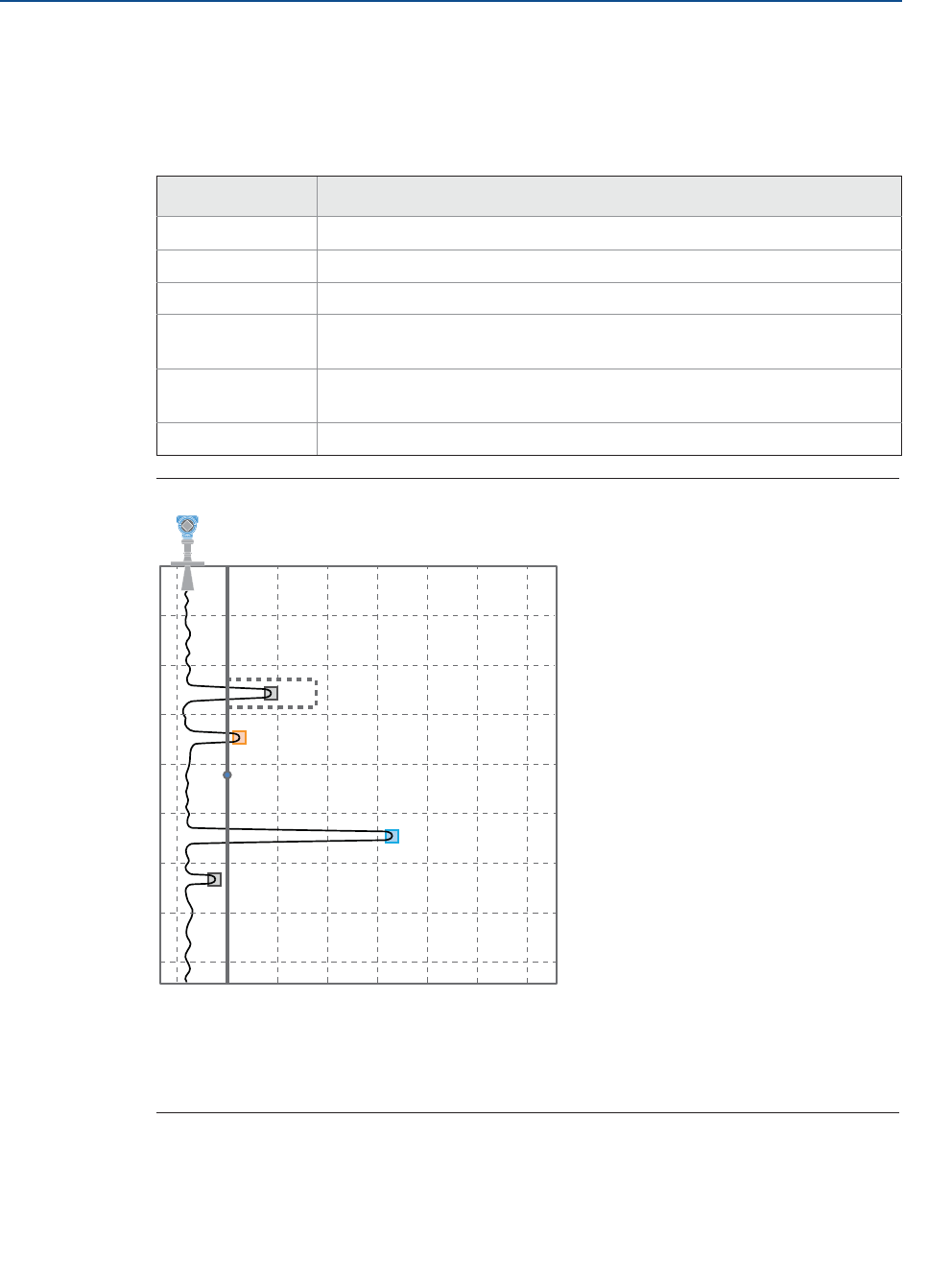
Analyze the echo curve
The following echo peaks may appear in the echo curve:
Table 7-8. Echo Peak Types
Figure 7-2. Echo Curve with Typical Echo Peaks
A. Suppressed (dashed line indicates use of false echo suppression)
B. Unknown
C. Amplitude threshold
D. Surface
Type Description
Surface Echo tracked as the current surface echo
Unknown Echo not recognized by the device, which might interfere with measurement
Suppressed Echoes that are identified but suppressed by the device
Suppressed
(double bounce)
Echo managed as a double bounce echo by the Double Bounce function
Secondary surface Echo tracked as the current secondary surface (if Double Surface Handling
function is enabled)
Tank bottom echo Echo considered as an echo from the tank bottom
B
meter
0
0 1 000 2 000 3 000 4 000 5 000 6 000 7 000 mV
0.5
1.0
1.5
2.0
2.5
3.0
3.5
C
A
D
A
89
Reference Manual
00809-0100-4408, Rev AA
Troubleshooting
November 2016
Troubleshooting
PRELIMINARY
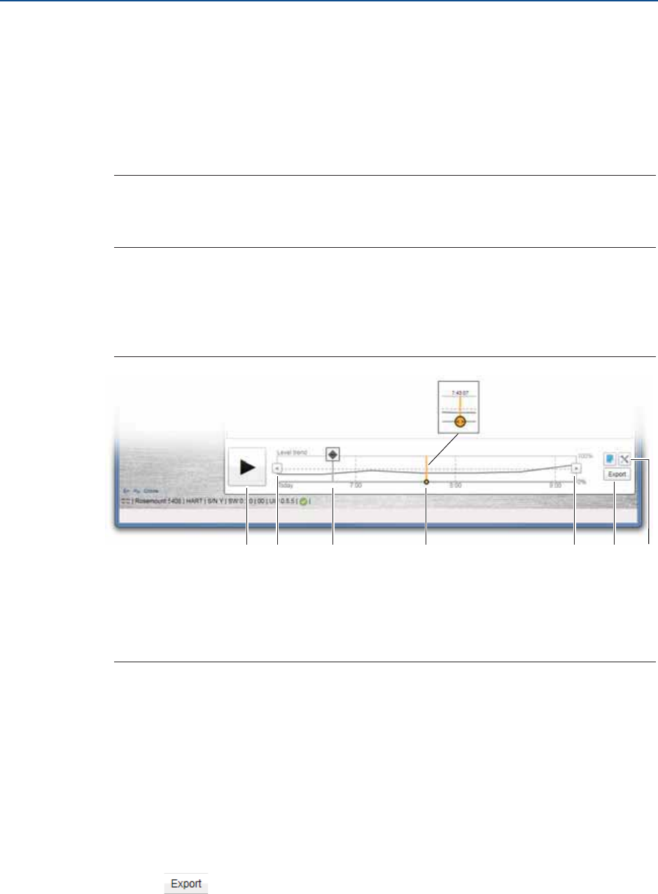
View level trends and historical echo curves
To go to a desired point in the displayed part of the timeline:
Drag the slider, or click anywhere in the timeline.
To move the timeline forward or backward:
Click the left or right arrow, or click and drag anywhere in the timeline.
Tip
To speed up the upload time of historical data, select Pause to halt the new echo curve
reading. Reading new echo curves have priority over uploading previously recorded data to
the timeline.
View active/historical alerts
In the timeline, click the left or right arrow to scroll to the alert, and then select the
alert icon for details.
Figure 7-3. Level Trend Timeline
A. Play or pause
B. Click left or right arrow, or click and drag anywhere in the timeline, to move the timeline forward or backward.
C. Click the alert icon for details.
D. Drag the slider, or click anywhere in the timeline, to go to a desired point in the displayed part of the timeline.
E. Export echo curves
F. Options
Play echo curve movies
1. Drag the slider to desired start point, or click the start point in the timeline.
2. Select Play.
Export echo curve movies
1. Under Service Tools, select Echo Curve.
2. Select the Export icon.
3. Browse to the desired directory.
A DB B E F
[PLACEHOLDER]
C
90
Reference Manual
00809-0100-4408, Rev AA
Troubleshooting
November 2016
Troubleshooting
PRELIMINARY
4. Type your desired file name and select Save.
5. TBD.
Set echo curve range
1. Under Service Tools, select Echo Curve.
2. Select the Options icon.
3. Under Echo Curve Range, enter the desired values.
4. Select Save.
5. Select Back.
Set timeline resolution
To set the resolution of the level trend timeline:
1. Under Service Tools, select Echo Curve.
2. Select the Options icon.
3. In the Timeline Resolution list, select the desired length (in hours) of the timeline.
4. Select Save.
5. Select Back.
7.4.2 Manage disturbance echoes
There are two general methods for managing disturbance echoes:
Set amplitude thresholds to filter out weak disturbance echoes and noise.
Use the suppress false echoes function to manage strong disturbance echoes.
Set amplitude thresholds
The amplitude thresholds are used to filter out noise and disturbing echoes from the
product surface echo. The transmitter uses certain criteria to decide which type of echo
peak that is detected. Only echoes above the amplitude threshold might be considered the
product surface. The amplitude threshold can either be set to a constant value, or split into
sections as defined by up to 10 anchor points.
If necessary, a customized amplitude threshold section can for instance be used to remove
the influence from the tank nozzle or disturbances close to the tank bottom. Additionally, it
might be needed in areas where there are occasionally strong echoes present, for instance
due to wide mixer blades. Suppressing false echoes may not be sufficient in those areas.

91
Reference Manual
00809-0100-4408, Rev AA
Troubleshooting
November 2016
Troubleshooting
PRELIMINARY
Note
Do not create a customized amplitude threshold section around echoes which are already
registered as false echoes.
General recommendations
Use the following best practices to apply custom threshold adjustments:
Generally, set amplitude threshold to about 10% of surface echo amplitude.
Do not set the amplitude threshold to less than 150 mV.
Procedure
It is recommended to adjust thresholds using Rosemount Radar Master.
To adjust the threshold value:
1. In Rosemount Radar Master, under Service Tools, select Echo Curve.
2. In the echo curve, click and drag the amplitude threshold point left or right, or in
the Threshold box, type the desired value.
3. Select Save.
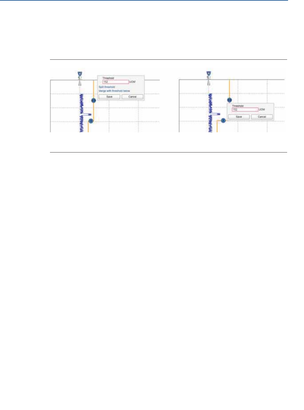
To add or delete an amplitude threshold point:
1. In the echo curve, click the desired amplitude threshold point, and select Split
threshold or Merge with threshold below.
2. Select Save.
92
Reference Manual
00809-0100-4408, Rev AA
Troubleshooting
November 2016
Troubleshooting
PRELIMINARY
To set the endpoint of a threshold segment:
1. In the echo curve, click and drag the endpoint up or down, or in the Split level box,
type the desired value.
2. Select Save.
Figure 7-4. Adjust Amplitude Thresholds
A. Amplitude threshold point
B. Endpoint
Suppress false echoes
Stationary objects with horizontal surfaces may generate strong false echoes. When the
surface is close to an obstruction in the tank (e.g. beams and agitators), the surface and
false echoes might interfere and cause a decrease in performance.
However, false echoes can be suppressed to reduce the influence of such objects, in case
they cannot be totally avoided. When the surface is passing by a disturbing object, the
transmitter will then measure with higher reliability, even if the surface echo is weaker than
the false echo, see Figure 7-5.
A
B
[PLACEHOLDER]
93
Reference Manual
00809-0100-4408, Rev AA
Troubleshooting
November 2016
Troubleshooting
PRELIMINARY
Figure 7-5. Suppression of False Echoes
A. Disturbing object
B. Amplitude threshold
C. Suppressed echo
D. Surface
Prerequisites
Follow these recommendations before suppressing new false echoes:
Make sure a correct amplitude threshold is set (see “Set amplitude thresholds” on
page 90).
Make sure the level is stable. A fluctuating level may indicate a temporary
disturbance which is not due to an interfering object.
Only suppress echoes which can be clearly identified as objects in the tank.
Compare the list of interfering echoes with the tank drawing or visual inspection of
the tank.
Do not suppress false echoes located below the product surface.
Keep the number of suppressed false echoes to a minimum.
It may be necessary to suppress new false echoes at a later stage when objects have
become visible due to surface movement.
meter
0
0 1 000 2 000 3 000 4 000 5 000 6 000 7 000 mV
0.5
1.0
1.5
2.0
2.5
3.0
3.5
C
A
B
D

94
Reference Manual
00809-0100-4408, Rev AA
Troubleshooting
November 2016
Troubleshooting
PRELIMINARY
Procedure
Rosemount Radar Master
1. Under Service Tools, select Echo Curve.
2. In the echo curve, click the square at the unknown echo peak, and then select
Suppress.
The false echo may also be suppressed manually if the position of the false echo is known.
1. Under Service Tools, select Echo Curve.
2. Select the Options icon.
3. Select Suppress False Echo Manually. Suppressed echoes are shown in the table
To add a new suppression, select Add, and then type the distance to the false
echo and the width of the false echo area.
To change a suppression, select the cell you want change and type the new
value.
To delete a suppression, select the row you want to delete, and then select
Delete.
4. Select Save.
5. Select Back.
AMS Device Manager and Field Communicator
1. From the Home screen, select Service Tools > Echo Tuning > Suppress.
Suppressed echoes are shown in the table.
2. Select Suppress or Remove Suppression.
3. Type the distance to the echo that should be added to or removed from the list.
7.4.3 Save and load configuration files
When configuration is finished, it is recommended to store the device configuration in a
backup file for future reference using Rosemount Radar Master. A backup of the device
configuration and a configuration report will be saved to file.
The backup file may be useful to:
Restore the configuration of the transmitter.
Install another transmitter in a similar tank.
Troubleshoot the transmitter.
Procedure
To save a backup file of the device configuration:

95
Reference Manual
00809-0100-4408, Rev AA
Troubleshooting
November 2016
Troubleshooting
PRELIMINARY
1. In Rosemount Radar Master, under Service Tools, select Maintenance.
2. Select Save Configuration.
3. Browse to the desired directory.
4. Type your desired file name and select Save.
To download configuration from file to device:
1. In Rosemount Radar Master, under Service Tools, select Maintenance.
2. Select Restore Configuration.
3. Browse to the backup file and select Open.
7.4.4 Restore to default settings
This function restores the transmitter to default settings (user configuration is overwritten).
Before restoring the transmitter to default settings, it is recommended to backup the
transmitter configuration, see “Save and load configuration files” on page 94. The backup
file can be used to restore configuration at a later stage.
Procedure
Rosemount Radar Master
1. Under Service Tools, select Maintenance > Reset/Restore.
2. Select Restore Default Settings and follow the on-screen instructions.
AMS Device Manager and Field Communicator
1. From the Home screen, select Service Tools > Maintenance > Reset/Restore.
2. Select Restore Default Settings and follow the on-screen instructions.
7.4.5 Calibrate analog out
Use this function to calibrate the analog output by comparing the actual output current
with the nominal 4 mA and 20 mA currents. Calibration is done at factory and the analog
output does not normally need to be recalibrated.
Procedure
Rosemount Radar Master
1. Under Service Tools, select Maintenance > Routine Maintenance.
2. Select Calibrate Analog Out and follow the on-screen instructions.
AMS Device Manager and Field Communicator
1. From the Home screen, select Service Tools > Maintenance > Routine
Maintenance.
2. Select D/A trim and follow the on-screen instructions.

96
Reference Manual
00809-0100-4408, Rev AA
Troubleshooting
November 2016
Troubleshooting
PRELIMINARY
7.4.6 Use the simulation mode
This function can be used to simulate measurements.
Procedure
Rosemount Radar Master
1. Under Service Tools, select Simulate.
2. Select desired transmitter variable and follow the on-screen instructions.
AMS Device Manager and Field Communicator
1. From the Home screen, select Service Tools > Simulate.
2. Under Simulate Measurement Values, select desired transmitter variable and follow
the on-screen instructions.
7.4.7 View input registers
Measured data is continuously stored in the input registers. By viewing the contents of the
input registers, expert users can check that the transmitter works properly.
Procedure
Rosemount Radar Master
1. Under Configure, select Level Setup > Advanced.
2. Under More Advanced Options, select Expert Options.
3. Select the Input Registers tab.
4. Under Show registers by, do one of the following:
Select Block, and then in the list, select the desired register group.
Select Number, and then type the desired register number.
5. Select Refresh.
AMS Device Manager and Field Communicator
1. From the Home screen, select Configure > Manual Setup > Level Setup >
Advanced > Expert Options > Input Registers.
2. Type the desired register number to start reading from.
3. Select Read Input Registers. 10 registers will be read, starting from the selected
number.

97
Reference Manual
00809-0100-4408, Rev AA
Troubleshooting
November 2016
Troubleshooting
PRELIMINARY
7.4.8 View/edit holding registers
The holding registers store various transmitter parameters, such as configuration data,
used to control the measurement performance.
Note
Do not use holding registers to configure the transmitter unless you are qualified. This
dialog is mainly used for service purposes and for advanced configuration.
Procedure
Rosemount Radar Master
1. Under Configure, select Level Setup > Advanced.
2. Under More Advanced Options, select Expert Options.
3. Select the Holding Registers tab.
4. Under Show registers by, do one of the following:
Select Block, and then in the list, select the desired register group.
Select Number, and then type the desired register number.
5. Select Refresh.
6. To change a holding register value, type a new value in the corresponding value
field, or select a new value from the corresponding list.
Some holding registers are edited in a separate window. In this case, individual data
bits can be changed.
7. Select Save to store the new value.
AMS Device Manager and Field Communicator
To view a holding register value:
1. From the Home screen, select Configure > Manual Setup > Level Setup >
Advanced > Expert Options > Holding Registers.
2. Type the desired register number to start reading from.
3. Select Read Holding Registers. 10 registers will be read, starting from the
selected number.
To edit a holding register value:
1. From the Home screen, select Configure > Manual Setup > Level Setup >
Advanced > Expert Options > Holding Registers.
2. Select Write Holding Registers and follow the on-screen instructions.

98
Reference Manual
00809-0100-4408, Rev AA
Troubleshooting
November 2016
Troubleshooting
PRELIMINARY
7.5 Write protect a transmitter
The transmitter can be write protected (with or without a password) to prevent
unauthorized changes.(1)
Procedure
Rosemount Radar Master
1. Under Overview, select Device Information > Security.
2. Under Write Protection, select Change and follow the on-screen instructions.
AMS Device Manager and Field Communicator
1. From the Home screen, select Configure > Manual Setup > Device Setup >
Security.
2. Under Security, select Change Write Protection and follow the on-screen
instructions.
1. If the Rosemount 5408:SIS is configured for use in Safety (SIS) operational mode, then the Safety Mode must be enabled for the
transmitter to become operational. When Safety Mode is enabled, the transmitter is write protected to prevent unauthorized changes.
Refer to “Configuration” on page 110 for more information.
99
Reference Manual
00809-0100-4408, Rev AA
Troubleshooting
November 2016
Troubleshooting
PRELIMINARY
7.6 Application challenges
7.6.1 Handling disturbances at top of tank
The Upper Null Zone defines a zone close to the transmitter where echoes are to be
ignored. As an alternative to a customized amplitude threshold section, the Upper Null
Zone can be extended to block out disturbing echoes at the top of the tank, for example
from the tank nozzle or bypass well inlet (see Figure 7-6).
Note
Make sure the Upper Range Value (100%/20 mA) value is below the Upper Null Zone.
Measurements are not performed within the Upper Null Zone.
Figure 7-6. Upper Null Zone
A. Upper Null Zone
B. Disturbance echo
C. Amplitude threshold
D. Product surface echo
Procedure
1. Identify desired Upper Null Zone using the echo curve plot.
a. In Rosemount Radar Master, start the echo curve reading, see “Use the echo
curve function” on page 87.
b. View the echo curve plot to find out if there are disturbing echoes close to the
transmitter.
2. Set the desired Upper Null Zone value.
a. Under Configure, select Level Setup > Antenna.
b. Under Advanced, type desired Upper Null Zone, and then select Save.
A
meter
0
0 1 000 2 000 3 000 4 000 5 000 6 000 7 000 mV
0.5
1.0
1.5
2.0
2.5
3.0
100% (20 mA)
B
C
D
100
Reference Manual
00809-0100-4408, Rev AA
Troubleshooting
November 2016
Troubleshooting
PRELIMINARY
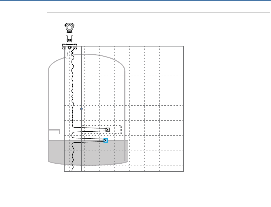
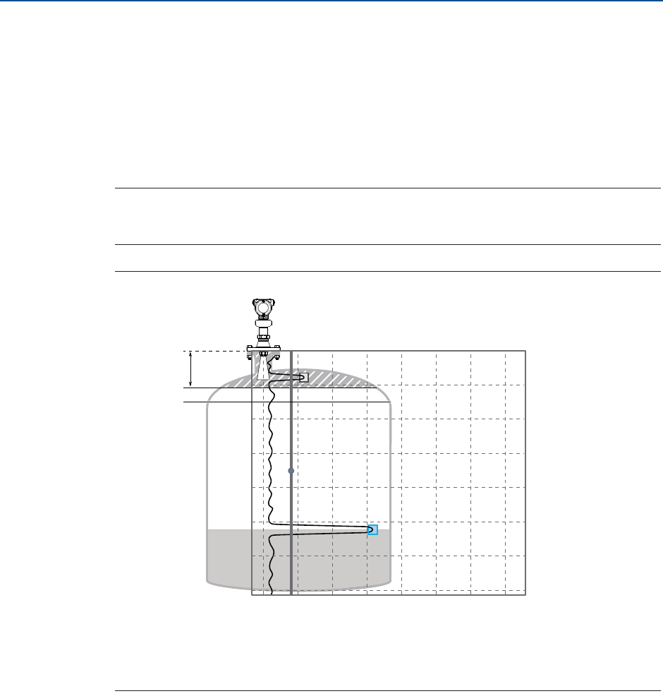
7.6.2 Tracking of weak surface echoes close to tank bottom
Use tank bottom projection
The Tank Bottom Projection function can be used to enhance measurement performance in
the tank bottom region. If the product surface echo is weak in the tank bottom region and
the bottom echo is strong (typical for flat tank bottoms), the transmitter may lock on the
bottom echo and report a false level measurement (empty tank). If the application requires,
the Tank Bottom Projection settings can be user-defined.
Figure 7-7 illustrates an example of the Tank Bottom Projection when the tank is being
emptied.
Figure 7-7. Tank Bottom Projection
Procedure
1. In Rosemount Radar Master, under Configure, select Level Setup > Advanced.
2. Under More Advanced Options, select Empty Tank Handling.
3. In the Tank Bottom Projection list, select Enabled or Disabled.
4. If you enabled Tank Bottom Projection, then:
a. Set the Bottom Product Dielectric Constant.
b. Enter Maximum Projection Distance.
c. Enter Minimum Tank Bottom Echo Amplitude.
Bottom product dielectric constant
Enter the product dielectric constant for the product in the bottom of the tank.
Maximum projection distance
This defines the range in which the function operates. Enter the maximum distance from
the zero level (tank bottom). It is recommended to use the default setting.
Minimum tank bottom echo amplitude
Enter the minimum allowed amplitude for the echo from the tank bottom before this
function is activated. It is recommended to use the default setting.
Enable bottom echo visible when tank is empty
Enable the Bottom echo visible when tank is empty parameter if a bottom echo is visible when
tank is empty (i.e. for flat tank bottoms). The bottom echo will then be treated as a
Time
Level Level
Time
Enabled Disabled
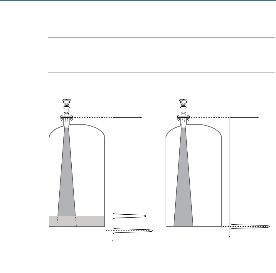
101
Reference Manual
00809-0100-4408, Rev AA
Troubleshooting
November 2016
Troubleshooting
PRELIMINARY
disturbance echo to facilitate tracking of weak surface echoes close to the tank bottom.
This function may be useful for products which are relatively transparent for microwaves,
such as oil.
Note
Only enable this parameter if a bottom echo is visible when tank is empty. To verify this, use
the echo curve function.
Figure 7-8. Bottom Echo Visible
A. Surface echo
B. Echo peak from tank bottom (at the electrical distance when product in the tank)
Procedure
1. In Rosemount Radar Master, under Configure, select Level Setup > Advanced.
2. Under More Advanced Options, select Empty Tank Handling.
3. In the Empty Tank Handling list, select User Defined.
4. Select the Bottom echo visible when tank is empty check box.
Distance
Signal amplitude
A
B
Distance
Signal amplitude
B
Empty tankProduct surface near
bottom of tank
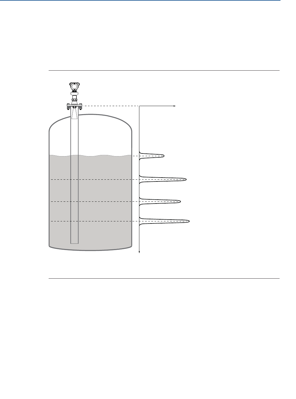
102
Reference Manual
00809-0100-4408, Rev AA
Troubleshooting
November 2016
Troubleshooting
PRELIMINARY
7.6.3 Handling ghost echoes in still pipes
Ghost echoes may occur in still pipes because of multiple reflections between the pipe wall,
flange, and antenna. In the echo curve, these echoes appear as amplitude peaks at various
distances below the product surface, see Figure 7-9. The Track First Echo function can
eliminate ghost echo problems below the product surface. When enabled, the first echo
above threshold will always be considered as the surface echo.
Figure 7-9. Ghost Echoes in Still Pipes
A. Actual level
B. Virtual level
Procedure
1. In Rosemount Radar Master, read the echo curve. Make sure there are no disturbing
echoes above the product surface. See “Use the echo curve function” on page 87.
2. Under Configure, select Level Setup > Advanced.
3. Under More Advanced Options, select Echo Tracking.
4. In the Surface Echo Tracking list, select User defined, and then select the Track First
Echo check box.
Distance
Signal amplitude
A
B
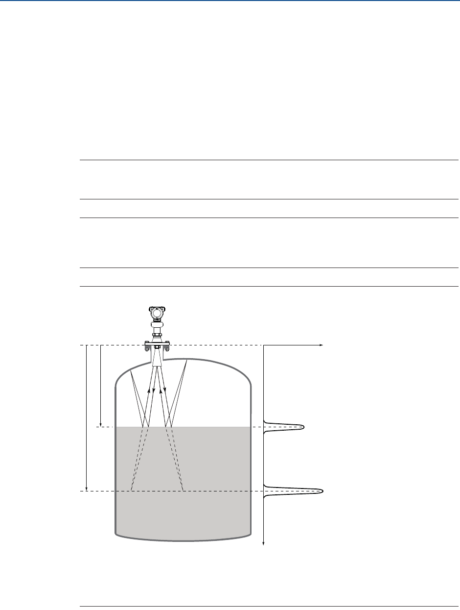
103
Reference Manual
00809-0100-4408, Rev AA
Troubleshooting
November 2016
Troubleshooting
PRELIMINARY
7.6.4 Handling strong double bounce echoes
A double bounce echo occurs when a radar signal bounces back and forth between the
product surface and tank roof (or other object within the tank) before it is detected by the
transmitter. Normally, these signals have a low amplitude and are ignored by the
transmitter.
Double bounces are most commonly present in spherical or horizontal cylinder tanks, and
usually appear when the tank is about 60-70% filled. In these cases, the amplitude may be
strong enough for the transmitter to interpret the double bounce as the surface echo. The
Double Bounce Handling function is used for managing such problems.
Note
The Double Bounce Handling function should only be used if the problem of double
bounces can not be solved by changing the mounting position.
Note
The surface echo is required to suppress the double bounce. If the surface echo enters the
Upper Null Zone (see page 174), there is no product surface reference and the double
bounce might be interpreted as the surface echo.
Figure 7-10. Double Bounce Echoes
A. Distance to surface
B. Distance to first double bounce
C. Actual level
D. Virtual level (first double bounce)
A
B
Distance
Signal amplitude
C
D

104
Reference Manual
00809-0100-4408, Rev AA
Troubleshooting
November 2016
Troubleshooting
PRELIMINARY
Procedure
1. In Rosemount Radar Master, read the echo curve plot to determine if double
bounce echoes are present, see “Use the echo curve function” on page 87.
2. Under Configure, select Level Setup > Advanced.
3. Under More Advanced Options, select Echo Tracking.
4. In the Double Bounce Handling list, select Enabled or Disabled.
5. If you enabled Double Bounce Handling, then enter desired Double Bounce Offset.
Double bounce offset
The distance between each double bounce echo is constant. The Double Bounce Offset is
used to define the distance between detected double bounces, as given by the following
formula (see Figure 7-10):
Double Bounce Offset = B - 2A
The Double Bounce Offset is negative if the reflection point (normally the tank roof) is
below the Tank Reference Point.
7.7 Service support
To expedite the return process outside of the United States, contact the nearest Emerson™
Process Management representative.
Within the United States, call the Emerson Process Management Instrument and Valve
Response Center using the 1-800-654-RSMT (7768) toll-free number. This center, available
24 hours a day, will assist you with any needed information or materials.
The center will ask for product model and serial numbers, and will provide a Return Material
Authorization (RMA) number. The center will also ask for the process material to which the
product was last exposed.
Emerson Process Management Instrument and Valve Response Center representatives will
explain the additional information and procedures necessary to return goods exposed to
hazardous substances.
Individuals who handle products exposed to a hazardous substance can avoid injury if they
are informed of and understand the hazard. The product being returned will require a copy
of the required Material Safety Data Sheet (MSDS) for each substance must be included
with the returned goods.

105
Reference Manual
00809-0100-4408, Rev AA
Safety Instrumented Systems (4-20 mA only)
November 2016
Safety Instrumented Systems (4-20 mA only)
PRELIMINARY
Section 8 Safety Instrumented Systems
(4-20 mA only)
Safety messages . . . . . . . . . . . . . . . . . . . . . . . . . . . . . . . . . . . . . . . . . . . . . . . . . . . . . . . . . page 105
Terms and definitions . . . . . . . . . . . . . . . . . . . . . . . . . . . . . . . . . . . . . . . . . . . . . . . . . . . . page 106
Safety Instrumented System (SIS) certification . . . . . . . . . . . . . . . . . . . . . . . . . . . . . . . page 108
Safety certified identification . . . . . . . . . . . . . . . . . . . . . . . . . . . . . . . . . . . . . . . . . . . . . . page 109
Installation . . . . . . . . . . . . . . . . . . . . . . . . . . . . . . . . . . . . . . . . . . . . . . . . . . . . . . . . . . . . . . page 110
Configuration . . . . . . . . . . . . . . . . . . . . . . . . . . . . . . . . . . . . . . . . . . . . . . . . . . . . . . . . . . . page 110
Proof-testing . . . . . . . . . . . . . . . . . . . . . . . . . . . . . . . . . . . . . . . . . . . . . . . . . . . . . . . . . . . . page 112
Specifications . . . . . . . . . . . . . . . . . . . . . . . . . . . . . . . . . . . . . . . . . . . . . . . . . . . . . . . . . . . page 119
8.1 Safety messages
Procedures and instructions in this section may require special precautions to ensure the
safety of the personnel performing the operation. Information that raises potential safety
issues is indicated by a warning symbol ( ). Refer to the following safety messages before
performing an operation preceded by this symbol.
Failure to follow safe installation and service guidelines could result in death or
serious injury.
Make sure only qualified personnel perform the installation.
Explosions could result in death or serious injury.
Verify that the operating environment of the transmitter is consistent with the
appropriate hazardous locations certifications.
Before connecting a Field Communicator in an explosive atmosphere, make sure
the instruments in the loop are installed in accordance with intrinsically safe or
non-incendive field wiring practices.
Do not remove the transmitter covers in explosive atmospheres when the circuit
is alive.
Both transmitter covers must be fully engaged to meet explosion-proof
requirements.
Electrical shock can result in death or serious injury.
Avoid contact with the leads and terminals. High voltage that may be present on
leads can cause electrical shock.
Make sure the main power to the transmitter is off and the lines to any other
external power source are disconnected or not powered while wiring the
transmitter.

106
Reference Manual
00809-0100-4408, Rev AA
Safety Instrumented Systems (4-20 mA only)
November 2016
Safety Instrumented Systems (4-20 mA
PRELIMINARY
8.2 Terms and definitions
Table 8-1. Terms and Definitions
Term Definition
BPCS Basic Process Control System
ȜDU Dangerous Undetected
ȜDD Dangerous Detected
ȜSU Safe Undetected
ȜSD Safe Detected
Diagnostic coverage Fraction of dangerous failures detected by automatic on-line diagnostic
tests.
Diagnostic test interval The time from when a dangerous failure/condition occurs until the
device has set the safety related output in a safe state (total time
required for fault detection and fault reaction).
FIT Failure In Time per billion hours
FMEDA Failure Modes, Effects and Diagnostic Analysis
HART®Highway Addressable Remote Transducer
HFT Hardware Fault Tolerance
High demand mode The safety function is only performed on demand, in order to transfer
the EUC (Equipment Under Control) into a specified safe state, and
where the frequency of demands is greater than one per year (IEC
61508-4).
Low demand mode The safety function is only performed on demand, in order to transfer
the EUC into a specified safe state, and where the frequency of demands
is no greater than one per year (IEC 61508-4).
Mission time The time from an instrumented system’s start-up until its replacement
or refurbishment to as-new condition.
PFDAVG Average Probability of Failure on Demand
Proof-test coverage factor The effectiveness of a proof-test is described using the coverage factor
which specifies the share of detected dangerous undetected failures
(ȜDU). The coverage factor is an indication of a proof-test’s effectiveness
to detect dangerous undetected faults.

107
Reference Manual
00809-0100-4408, Rev AA
Safety Instrumented Systems (4-20 mA only)
November 2016
Safety Instrumented Systems (4-20 mA only)
PRELIMINARY
Safety deviation The maximum allowed deflection of the safety output due to a failure
within the device (expressed as a percentage of span).
Any failure causing the device output to change less than the Safety
Deviation is considered as a "No Effect" failure. All failures causing the
device output to change more than the Safety Deviation and with the
device output still within the active range (non-alarm state) are
considered dangerous failures.
Note that the Safety Deviation is independent of the normal
performance specification or any additional application specific
measurement error.
SFF Safe Failure Fraction
SIF Safety Instrumented Function
SIL Safety Integrity Level – a discrete level (one out of four) for specifying
the safety integrity requirements of the safety instrumented functions
to be allocated to the safety instrumented systems. SIL 4 has the
highest level of safety integrity, and SIL 1 has the lowest level.
SIS Safety Instrumented System – an instrumented system used to
implement one or more safety instrumented functions. An SIS is
composed of any combination of sensors, logic solvers, and final
elements.
Systematic Capability Systematic Capability is a measure (expressed on a scale of SC 1 to SC 4)
of the confidence that the systematic safety integrity of an element
meets the requirements of the specified SIL, in respect of the specified
element safety function, when the element is applied in accordance
with the instructions specified in the compliant item safety manual for
the element.
Transmitter response time The time from a step change in the process until transmitter output
reaches 90% of its final steady state value (step response time as per IEC
61298-2).
Type B device Complex device using controllers or programmable logic, as defined by
the standard IEC 61508.
Useful lifetime Useful lifetime is a reliability engineering term that describes the
operational time interval where the failure rate of a device is relatively
constant. It is not a term which covers product obsolescence, warranty,
or other commercial issues.
Term Definition
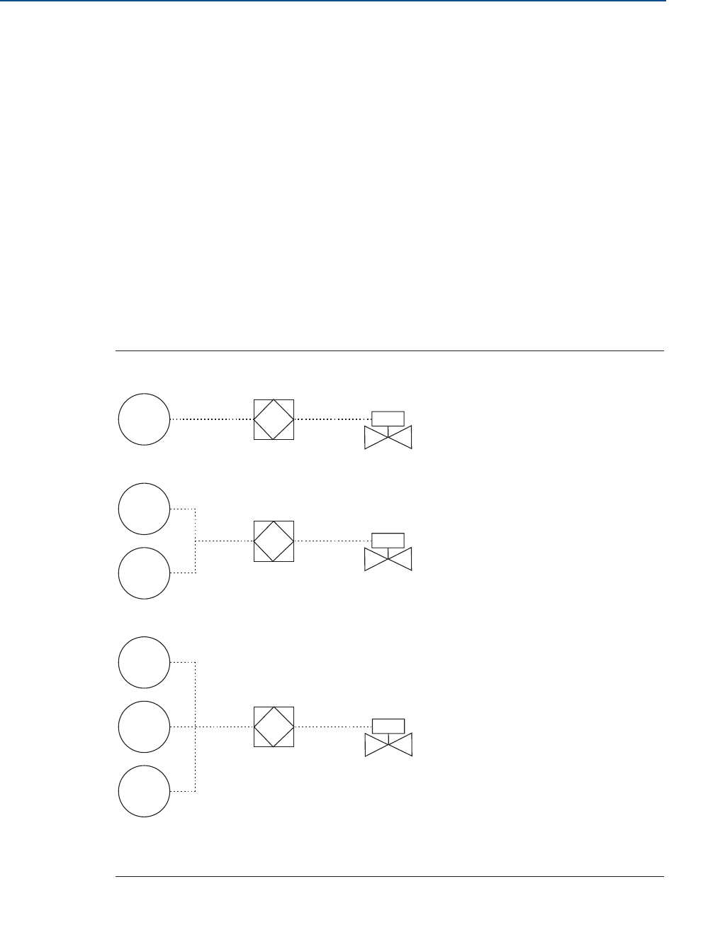
108
Reference Manual
00809-0100-4408, Rev AA
Safety Instrumented Systems (4-20 mA only)
November 2016
Safety Instrumented Systems (4-20 mA
PRELIMINARY
8.3 Safety Instrumented System (SIS) certification
For safety instrumented systems usage, the 4-20 mA analog output is used as the primary
safety variable. It is configured to activate the alarm function if an error occurs. If a
measured value goes beyond the measurement range, the transmitter enters saturation
mode.
The measurement signal used by the logic solver must be the analog 4-20 mA signal
proportional to the level or distance (ullage) generated. The HART protocol can only be
used for setup, calibration, and diagnostic purposes, not for safety critical operation.
The Rosemount™ 5408:SIS Level Transmitter is IEC 61508 certified accordingly:
Low and high demand: Type B element
SIL 2 for random integrity @ HFT=0
SIL 3 for random integrity @ HFT=1
SIL 3 for systematic capability
Figure 8-1. SIF Configuration Examples
A. Rosemount 5408:SIS Level Transmitter (sensor)
B. Logic-solver
C. Actuator
LT
LT
LT
LT
LT
LT
A
A
A
B
C
B
C
B
C
Single use 1oo1 (1-out-of-1) for SIL2
(SIL 2@ HFT=0)
Redundant use 1oo2 for SIL3
(SIL3@ HFT=1)
Redundant use 2oo3 for SIL3
(SIL3@ HFT=2)
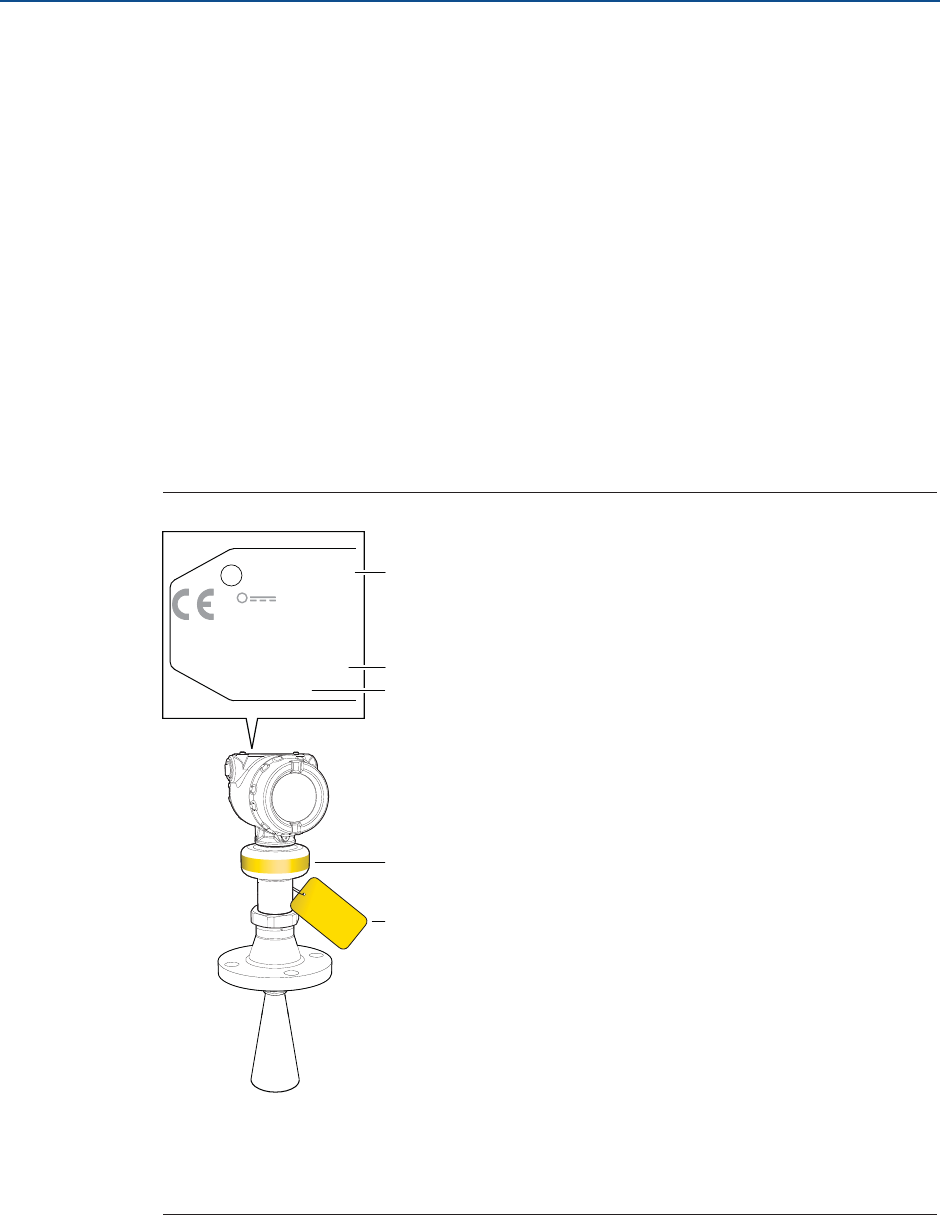
109
Reference Manual
00809-0100-4408, Rev AA
Safety Instrumented Systems (4-20 mA only)
November 2016
Safety Instrumented Systems (4-20 mA only)
PRELIMINARY
Application examples
Level range monitoring
Dry-run prevention
Overfill prevention
8.4 Safety certified identification
All Rosemount 5408:SIS Level Transmitters must be identified as safety certified before
installing into SIS systems.
Verify that:
1. The transmitter model code starts with 5408F.
2. The software (SW) is 1.A2 or later.
Figure 8-2. Identification
A. Model code
B. Serial number
C. SW version
D. Yellow stripe for locating device from distance
E. Yellow tag for locating device from distance
SIL 2
0682
!
8045C8K:
DI
C
CF
8045
-
A72
82 C
I
DVE
EC
IVER
PCO
T
OROL
5408FXXXXXXXXXXXXXXXXXXXXXXX
X
X
LT-XXXXXXXXXX
HART® 4-20 mA
12-XX.X V DC
23 mA
SERIAL NO
XXXXXXXXXXXX
DATE MFG XX-XX
HW/SW X.X.X/1.A2
D
A
B
C
E

110
Reference Manual
00809-0100-4408, Rev AA
Safety Instrumented Systems (4-20 mA only)
November 2016
Safety Instrumented Systems (4-20 mA
PRELIMINARY
8.5 Installation
The Rosemount 5408:SIS must be installed and configured as described in Section 3:
Mechanical Installation and Section 4: Electrical Installation. No special installation is
required in addition to the standard installation practices outlined in this manual.
The loop should be designed so the terminal voltage is within the limits specified in section
“Power supply” on page 124.
Check that environmental conditions do not exceed the ratings in Appendix A:
Specifications and Reference Data.
Note
The Rosemount 5408:SIS Level Transmitter is not safety-rated during maintenance work,
configuration changes, multidrop, loop test, proof-test, or other activity that affects the
safety function. Alternative means should be used to ensure process safety during such
activities.
8.5.1 Measuring range
The recommended measuring range is up to 82 ft. (25 m) for the Rosemount 5408:SIS Level
Transmitter. Refer to Appendix A: Specifications and Reference Data for performance
specification data.
8.6 Configuration
Use a HART-compliant master, such as Rosemount Radar Master, AMS™ Device Manager or a
Field Communicator, to communicate with and verify configuration of the Rosemount
5408:SIS.
8.6.1 Prerequisites
Before doing any configuration, write down the serial number from the transmitter label
(see Figure 8-2 on page 109), and make sure you are connected to the correct transmitter
by verifying the same serial number in your configuration tool.
Rosemount Radar Master
Under Overview, select Device Information > Identification.
AMS Device Manager and Field Communicator
From the Home screen, select Overview > Device Information > Identification.
8.6.2 Configure device using Guided Setup
Follow the Guided Setup wizard for transmitter configuration, refer to Section 5:
Configuration. When configuring parameters not included in the Guided Setup, it may be
necessary to do additional verification.

111
Reference Manual
00809-0100-4408, Rev AA
Safety Instrumented Systems (4-20 mA only)
November 2016
Safety Instrumented Systems (4-20 mA only)
PRELIMINARY
8.6.3 Set operational mode
The Rosemount 5408:SIS can be used as the level sensor in a BPCS or as a safety device in a
safety instrumented system.
If the Rosemount 5408:SIS is used as safety device in a Safety Instrumented System, then
the operational mode must be set to Safety (SIS). The Safety (SIS) operational mode can be
activated via the Guided Setup wizard, or as follows:
Rosemount Radar Master
1. Under Configure, select Device Setup > Security.
2. Under Operational Mode, select Change and follow the on-screen instructions.
AMS Device Manager and Field Communicator
1. From the Home screen, select Configure > Manual Setup > Device Setup >
Security.
2. Under Safety Instrumented Systems, select Change Operation Mode and follow the
on-screen instructions.
Note
When entering the Safety (SIS) operational mode, the analog output will be put into alarm
mode until the Safety Mode is enabled.
8.6.4 Enable safety mode
If the transmitter is configured for use in Safety (SIS), then the Safety Mode must be enabled
for the transmitter to become operational. When Safety Mode is enabled, the transmitter is
write protected (with or without a password) to prevent unauthorized changes.
Rosemount Radar Master
1. Under Configure, select Device Setup > Security.
2. Under Safety Mode, select Change and follow the on-screen instructions.
AMS Device Manager and Field Communicator
1. From the Home screen, select Configure > Manual Setup > Device Setup >
Security.
2. Under Safety Instrumented Systems, select Change Safety Mode and follow the
on-screen instructions.
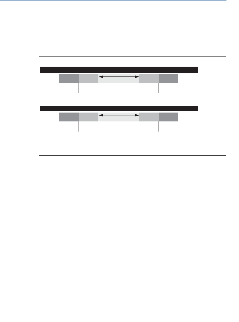
112
Reference Manual
00809-0100-4408, Rev AA
Safety Instrumented Systems (4-20 mA only)
November 2016
Safety Instrumented Systems (4-20 mA
PRELIMINARY
8.6.5 Alarm and saturation levels
DCS or safety logic solver should be configured to handle both High alarm and Low alarm. In
addition, the transmitter must be configured for High or Low alarm (see “Alarm mode” on
page 163).
Figure 8-3 identifies the alarm levels available and their operation values(1).
Figure 8-3. Alarm Levels and Operation Values
8.7 Site acceptance
After installation and/or configuration, proper operation of the transmitter (including
verification of all configuration changes) must be verified. A site acceptance test is therefore
recommended. The proof-tests outlined in section “Proof-testing” on page 112 can be used
for this.
8.8 Proof-testing
8.8.1 Overview
The Rosemount 5408:SIS Level Transmitter must be tested at regular intervals to reveal
faults which are undetected by automatic diagnostics. It is the user's responsibility to
choose the type of testing and the frequency of these tests.
Results from periodic proof-tests shall be recorded and periodically reviewed. If an error is
found in the safety functionality, the transmitter shall be put out of operation and the
process shall be kept in a safe state by other measures.
1. Note that during startup, the Rosemount 5408:SIS always outputs Low alarm current even if the transmitter is configured for High
alarm mode.
Rosemount Alarm Level
Normal Operation
3.75 mA(1)
1. Transmitter Failure, hardware or software alarm in Low position.
4 mA 20 mA 21.75 mA(2)
3.9 mA
low saturation
20.8 mA
high saturation
Namur Alarm Level
Normal Operation
3.6 mA(1) 4 mA 20 mA 22.5 mA(2)
2. Transmitter Failure, hardware or software alarm in High position.
3.8 mA
low saturation
20.5 mA
high saturation
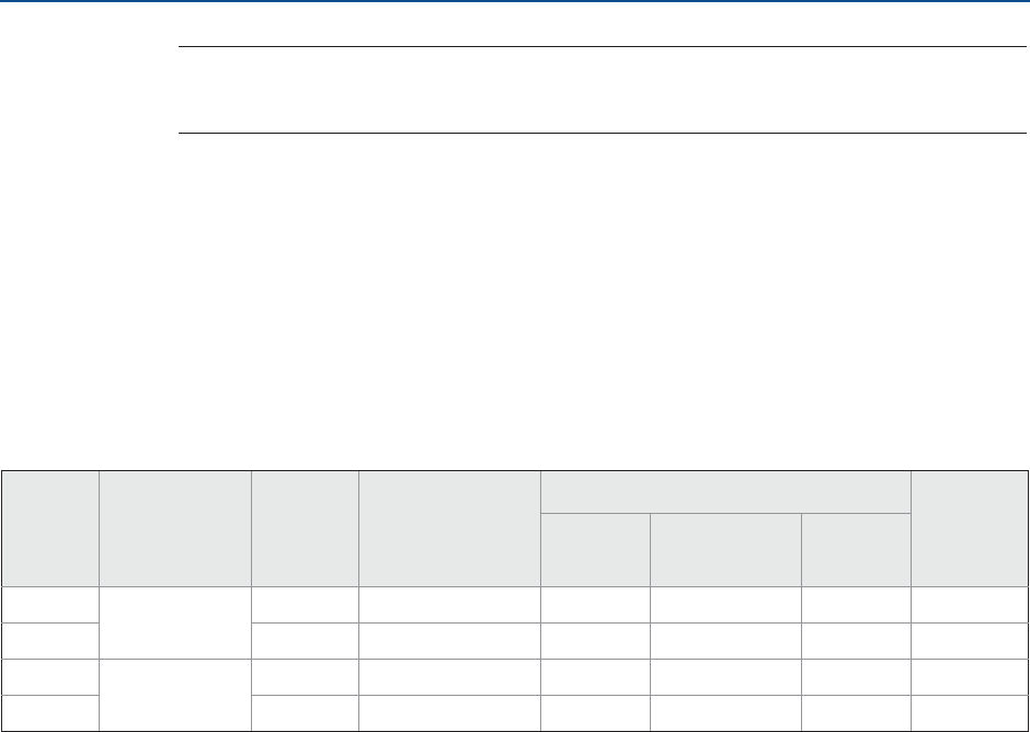
113
Reference Manual
00809-0100-4408, Rev AA
Safety Instrumented Systems (4-20 mA only)
November 2016
Safety Instrumented Systems (4-20 mA only)
PRELIMINARY
Note
For a valid result, always perform the proof-test on the product that will be stored in the
tank while the device is in operation.
The following proof-tests are suggested:
(A) 1-point level and analog output verification (see page 114)
(B) 2-point level and analog output verification (see page 116)
(C) Analog output verification (see page 118)
(D) Level deviation monitoring (see page 118)
Table 8-2 can be used as a guidance for selecting the appropriate proof-test.
Table 8-2. Suggested Proof-tests
Proof-test interval
The time intervals for proof-testing are defined by the SIL verification calculation (subject to
the PFDAVG). The SIL verification calculation is an analytical method to calculate an
appropriate proof-test interval for the specific safety function based on equipment’s
reliability and required risk reduction for the specific SIF.
The proof-tests must be performed more frequently than or as frequently as specified in the
SIL verification calculation, in order to maintain the required safety integrity of the overall
SIF.
Tools required
HART host/communicator or Rosemount Radar Master
Current meter
Safety logic solver
Independent measuring device (e.g. BPCS level sensor, measuring tape)
Proof-
test #
Type Proof-test
coverage
(%) of DU
Remaining
dangerous,
undetected
failures
Test coverage Can be
performed
remotely
Output
circuitry
Measurement
electronics
Antenna
AComprehensive XX xx FIT Y Y Y Y(1)
1. With the assumption that the BPCS level sensor is used as independent measurement.
BXX xx FIT Y Y Y Y(1)
CPartial XX xx FIT Y N N Y
DXX xx FIT N Y N Y

114
Reference Manual
00809-0100-4408, Rev AA
Safety Instrumented Systems (4-20 mA only)
November 2016
Safety Instrumented Systems (4-20 mA
PRELIMINARY
8.8.2 1-point level and analog output verification
1. Prior to the test, ensure there are no alarms or warnings present in the transmitter.
2. Bypass the safety function and take appropriate action to avoid a false trip.
3. Output fixed 4.00 mA current and measure the loop current (e.g. using the safety
logic solver or current meter).
During the proof-test, the transmitter will not output measurement values
corresponding to the product surface level. Make sure systems and people relying on
measurement values from the transmitter are made aware of the changed conditions.
Failure to do so could result in death, serious injury and/or property damage.
Rosemount Radar Master: AMS Device Manager and
Field Communicator:
Under Service Tools, select Alerts.From the Home screen, select Service
Tools > Alerts.
Rosemount Radar Master: AMS Device Manager and
Field Communicator:
a. Under Service Tools, select Simulate.
b. Select Loop Test.
c. Select 4 mA and then select Start.
d. Measure loop current.
e. Verify the current deviation is within the
safety deviation of 2% (±0.32 mA).
Note: The inaccuracy of safety logic
solver or current meter needs to be
considered.
f. Select Stop to end loop test.
a. From the Home screen, select Service
Tools > Simulate.
b. Select Loop Test.
c. Select 4 mA and then select Next.
d. Measure loop current.
e. Verify the current deviation is within
the safety deviation of 2% (±0.32 mA).
Note: The inaccuracy of safety logic
solver or current meter needs to be
considered.
f. Select End and then select Next to end
loop test.

115
Reference Manual
00809-0100-4408, Rev AA
Safety Instrumented Systems (4-20 mA only)
November 2016
Safety Instrumented Systems (4-20 mA only)
PRELIMINARY
4. Output fixed 20.00 mA current and measure the loop current (e.g. using the safety
logic solver or current meter).
5. Perform a one-point level measurement verification of the transmitter in the
measuring range. Compare with independent measurement (e.g. the BPCS level
sensor).
6. Remove the bypass and otherwise restore normal operation.
Rosemount Radar Master: AMS Device Manager and
Field Communicator:
a. Under Service Tools, select Simulate.
b. Select Loop Test.
c. Select 20 mA and then select Start.
d. Measure loop current.
e. Verify the current deviation is within the
safety deviation of 2% (±0.32 mA).
Note: The inaccuracy of safety logic
solver or current meter needs to be
considered.
f. Select Stop to end loop test.
a. From the Home screen, select Service
Tools > Simulate.
b. Select Loop Test.
c. Select 20 mA and then select Next.
d. Measure loop current.
e. Verify the current deviation is within
the safety deviation of 2% (±0.32 mA).
Note: The inaccuracy of safety logic
solver or current meter needs to be
considered.
f. Select End and then select Next to end
loop test.
Rosemount Radar Master: AMS Device Manager and
Field Communicator:
a. Under Overview, select All Variables.
b. Verify the current level or distance
reading with an independent
measurement is within the safety
deviation of 2%.
Note: The inaccuracy of the independent
measurement needs to be considered.
a. From the Home screen, select Service
Tools > Variables > Process.
b. Verify the current level or distance
reading with an independent
measurement is within the safety
deviation of 2%.
Note: The inaccuracy of the
independent measurement needs to
be considered.

116
Reference Manual
00809-0100-4408, Rev AA
Safety Instrumented Systems (4-20 mA only)
November 2016
Safety Instrumented Systems (4-20 mA
PRELIMINARY
8.8.3 2-point level and analog output verification
1. Prior to the test, ensure there are no alarms or warnings present in the transmitter.
2. Bypass the safety function and take appropriate action to avoid a false trip.
3. Output fixed 4.00 mA current and measure the loop current (e.g. using the safety
logic solver or current meter).
During the proof-test, the transmitter will not output measurement values
corresponding to the product surface level. Make sure systems and people relying on
measurement values from the transmitter are made aware of the changed conditions.
Failure to do so could result in death, serious injury and/or property damage.
Rosemount Radar Master: AMS Device Manager and
Field Communicator:
Under Service Tools, select Alerts.From the Home screen, select Service
Tools > Alerts.
Rosemount Radar Master: AMS Device Manager and
Field Communicator:
a. Under Service Tools, select Simulate.
b. Select Loop Test.
c. Select 4 mA and then select Start.
d. Measure loop current.
e. Verify the current deviation is within the
safety deviation of 2% (±0.32 mA).
Note: The inaccuracy of safety logic
solver or current meter needs to be
considered.
f. Select Stop to end loop test.
a. From the Home screen, select Service
Tools > Simulate.
b. Select Loop Test.
c. Select 4 mA and then select Next.
d. Measure loop current.
e. Verify the current deviation is within
the safety deviation of 2% (±0.32 mA).
Note: The inaccuracy of safety logic
solver or current meter needs to be
considered.
f. Select End and then select Next to end
loop test.

117
Reference Manual
00809-0100-4408, Rev AA
Safety Instrumented Systems (4-20 mA only)
November 2016
Safety Instrumented Systems (4-20 mA only)
PRELIMINARY
4. Output fixed 20.00 mA current and measure the loop current (e.g. using the safety
logic solver or current meter).
5. Perform a two-point level measurement verification of the transmitter in the
measuring range. Compare with independent measurement (e.g. the BPCS level
sensor).
6. Remove the bypass and otherwise restore normal operation.
Rosemount Radar Master: AMS Device Manager and
Field Communicator:
a. Under Service Tools, select Simulate.
b. Select Loop Test.
c. Select 20 mA and then select Start.
d. Measure loop current.
e. Verify the current deviation is within the
safety deviation of 2% (±0.32 mA).
Note: The inaccuracy of safety logic
solver or current meter needs to be
considered.
f. Select Stop to end loop test.
a. From the Home screen, select Service
Tools > Simulate.
b. Select Loop Test.
c. Select 20 mA and then select Next.
d. Measure loop current.
e. Verify the current deviation is within
the safety deviation of 2% (±0.32 mA).
Note: The inaccuracy of safety logic
solver or current meter needs to be
considered.
f. Select End and then select Next to end
loop test.
Rosemount Radar Master: AMS Device Manager and
Field Communicator:
a. Under Overview, select All Variables.
b. Verify the current level or distance
reading with an independent
measurement is within the safety
deviation of 2%.
Note: The inaccuracy of the independent
measurement needs to be considered.
c. Move the surface in the tank at least 10%
of the full measuring span (level 0-100%).
d. Repeat steps (a) to (b) for the second
point.
a. From the Home screen, select Service
Tools > Variables > Process.
b. Verify the current level or distance
reading with an independent
measurement is within the safety
deviation of 2%.
Note: The inaccuracy of the
independent measurement needs to
be considered.
c. Move the surface in the tank at least
10% of the full measuring span (level
0-100%).
d. Repeat steps (a) to (b) for the second
point.

118
Reference Manual
00809-0100-4408, Rev AA
Safety Instrumented Systems (4-20 mA only)
November 2016
Safety Instrumented Systems (4-20 mA
PRELIMINARY
8.8.4 Analog output verification
Compare HART Primary Variable digital value with analog output reading. Verify that the
deviation is within the pass limit.
1. Obtain the loop current as a digital value.
In Rosemount Radar Master, under Overview, select All Variables and read
the current analog output value.
OR
Read HART command 2 or 3 via the host system.(1)
2. Obtain the loop current as an analog value (e.g. by using the safety logic solver).
3. Compare the current values.
4. Verify the current deviation is within the safety deviation of 2% (±0.32 mA).
Note: The inaccuracy of safety logic solver needs to be considered.
8.8.5 Level deviation monitoring
Use the analog output to obtain level (or distance) reading and compare with an
independent level measurement. Verify that the deviation is within the pass limit.
1. Obtain the level (or distance) measurement value derived from the analog output
(e.g. by checking measurement value in safety logic solver).
2. Obtain the level (or distance) measurement value from an independent level
measurement (e.g. the BPCS level sensor).
3. Compare the measurements and verify that the deviation is within the pass limit.
8.8.6 Product repair
The Rosemount 5408:SIS is repairable by major component replacement. All failures
detected by the transmitter diagnostics or by the proof-test must be reported. Feedback
can be submitted electronically at EmersonProcess.com/Rosemount-safety (Contact Us).
1. Command 2: Analog output current and Percent of range
Command 3: Device variables (PV, SV, TV and QV) and Analog output current

119
Reference Manual
00809-0100-4408, Rev AA
Safety Instrumented Systems (4-20 mA only)
November 2016
Safety Instrumented Systems (4-20 mA only)
PRELIMINARY
8.9 Specifications
The Rosemount 5408:SIS must be operated according to the functional and performance
specifications provided in Appendix A: Specifications and Reference Data.
Failure rate data
The FMEDA report includes failure rate data, assessment details, and assumptions regarding
failure rate analysis. The full report is accessible at:
EmersonProcess.com/Rosemount-Safety
Safety deviation
+/-2.0% of analog output span under reference conditions
Transmitter response time(1)(2)
< 6 s at damping value 2 s (default)
< 2 s at damping value 0 s (minimum)
Diagnostic test interval(3)
< 90 min (< 30 s (default) for xx% of self-diagnostic tests)
Turn-on time(4)
< 40 s
Useful lifetime(5)
XX years
8.10 SIS loop example
This section will include PFDavg vs time graphs for the proof-tests at different proof-test
intervals.
1. Step response time as per IEC 60298-2.
2. The transmitter response time will be a function of the configured Damping value. Rosemount Radar Master has a built-in function to
calculate the transmitter’s measurement response time (select Configure > Device Setup > HART > Calculate Response Time).
3. The fault reaction time depends on the configured Alarm Delay (default value is 30 seconds). The Alarm Delay parameter controls the
maximum time from when a fault condition is detected until it is annunciated, see “Alarm delay” on page 178.
4. Time from when power is applied to the transmitter until performance is within specifications.
5. Estimated useful lifetime; see the FMEDA report for more information.

120
Reference Manual
00809-0100-4408, Rev AA
Safety Instrumented Systems (4-20 mA only)
November 2016
Safety Instrumented Systems (4-20 mA
PRELIMINARY

121
Specifications and Reference Data
Specifications and Reference Data
November 2016
Reference Manual
00809-0100-4408, Rev AA
PRELIMINARY
Appendix A Specifications and Reference
Data
Performance specifications . . . . . . . . . . . . . . . . . . . . . . . . . . . . . . . . . . . . . . . . . . . . . . . . page 121
Functional specifications . . . . . . . . . . . . . . . . . . . . . . . . . . . . . . . . . . . . . . . . . . . . . . . . . . page 122
Physical specifications . . . . . . . . . . . . . . . . . . . . . . . . . . . . . . . . . . . . . . . . . . . . . . . . . . . . page 126
Ordering information . . . . . . . . . . . . . . . . . . . . . . . . . . . . . . . . . . . . . . . . . . . . . . . . . . . . . page 129
Dimensional drawings . . . . . . . . . . . . . . . . . . . . . . . . . . . . . . . . . . . . . . . . . . . . . . . . . . . . page 140
A.1 Performance specifications
A.1.1 General
Reference conditions
Measurement target: Metal plate, no disturbing objects
Temperature: 68 to 86 °F (20 to 30 °C)
Ambient pressure: 14 to 15 psi (960 to1060 mbar)
Relative humidity: 25-75%
Instrument accuracy (under reference conditions)(1)
± 0.08 in. (2 mm)
Repeatability
±0.04 in. (±1 mm)
Resolution
TBD
Ambient temperature effect
TBD
Ambient temperature hysteresis
TBD
Vibration effect
TBD
Process temperature effect
TBD
Electromagnetic interference effect(2)
TBD
Sensor update rate
TBD
Maximum level rate
TBD
A.1.2 Measuring range
Maximum measuring range(3)
Rosemount 5408: 130 ft (40 m)
Rosemount 5408:SIS: 82 ft (25 m)
Blind zones
The measuring range is limited by the Blind Zones at the
very top and bottom of the tank. In the Blind Zones, the
accuracy exceeds ±TBD in. (TBD mm), and measurements
may not be possible. Measurements close to the Blind
Zones will have reduced accuracy.
Figure A-1. Accuracy Over Measuring Range
1. Refer to the IEC 60770-1 (IEC 1292-2) standard for a definition of
radar specific performance parameters and if applicable correspond-
ing test procedure.
2. Deviation through electromagnetic interference according to EN
61326.
3. Note that a combination of adverse process conditions, such as
heavy turbulence, foam and condensation, together with products
with poor reflection may affect the measuring range.
[PLACEHOLDER]
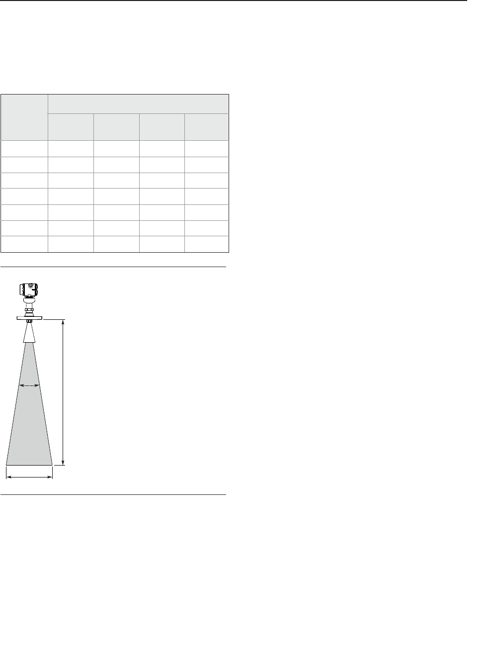
Specifications and Reference Data
November 2016
Reference Manual
00809-0100-4408, Rev AA
122 Specifications and Reference Data
PRELIMINARY
Beam angle
2-in. cone antenna: 18°
3-in. cone antenna: 14°
4-in. cone antenna: 10°
Parabolic antenna: 4.5°
Beam width
Figure A-2. Beam Width and Beam Angle
A.1.3 Environment
Vibration resistance
No effect when tested per the requirements of:
IEC61298-3, level “field with general application”
IACS UR E10 test 7
Electromagnetic compatibility (EMC)
EMC Directive (2014/30/EU): EN 61326-1:2013
EN 61326-2-3:2013
Pressure Equipment Directive (PED)
Complies with 2014/68/EU article 3.3
Built-in lightning protection
EN 61326, IEC 61000-4-5, level 6kV
Radio approvals
Complies with:
Radio Equipment Directive (2014/53/EU): ETSI EN 302
372, ETSI EN 302 729 and EN 62479
Part 15 of the FCC Rules
Industry Canada RSS 211
A.2 Functional specifications
A.2.1 General
Field of application
Continuous level measurements for tank monitoring,
process control, and overfill prevention on a broad range of
liquids and slurries.
Ideal for applications with varying and harsh process
conditions, such as heavy turbulence, foaming, product
build-up, condensing vapors, sticky, viscous, corrosive, and
crystallizing products.
Measurement principle
Frequency Modulated Continuous Wave (FMCW), 26 GHz
Frequency range
24.05 to 27.0 (26.5(1)) GHz
Maximum output power
-5 dBm (0.32 mW)
Internal power consumption
< 1 W in normal operation
Humidity
0 - 100% relative humidity, non-condensing
Turn-on time(2)
< 40 s
Distance
(D), ft (m)
Beam width (W), ft (m)
2-in. cone 3-in. cone 4-in.
cone Parabolic
16 (5) 5.2 (1.6) 4.0 (1.2) 2.9 (0.9) 1.3 (0.4)
33 (10) 10.4 (3.2) 8.1 (2.5) 5.7 (1.8) 2.6 (0.8)
49 (15) 15.6 (4.8) 12.1 (3.7) 8.6 (2.6) 3.9 (1.2)
66 (20) 20.8 (6.3) 16.1 (4.9) 11.5 (3.5) 5.2 (1.6)
82 (25) 26.0 (7.9) 20.1 (6.1) 14.3 (4.4) 6.4 (2.0)
98 (30) 31.2 (9.5) 24.2 (7.4) 17.2 (5.3) 7.7 (2.4)
131 (40) 41.6 (12.7) 32.2 (9.8) 23.0 (7.0) 10.3 (3.1)
D
D
W
1. For LPR (Level Probing Radar), option code OA.
2. Time from when power is applied to the transmitter until
performance is within specifications.
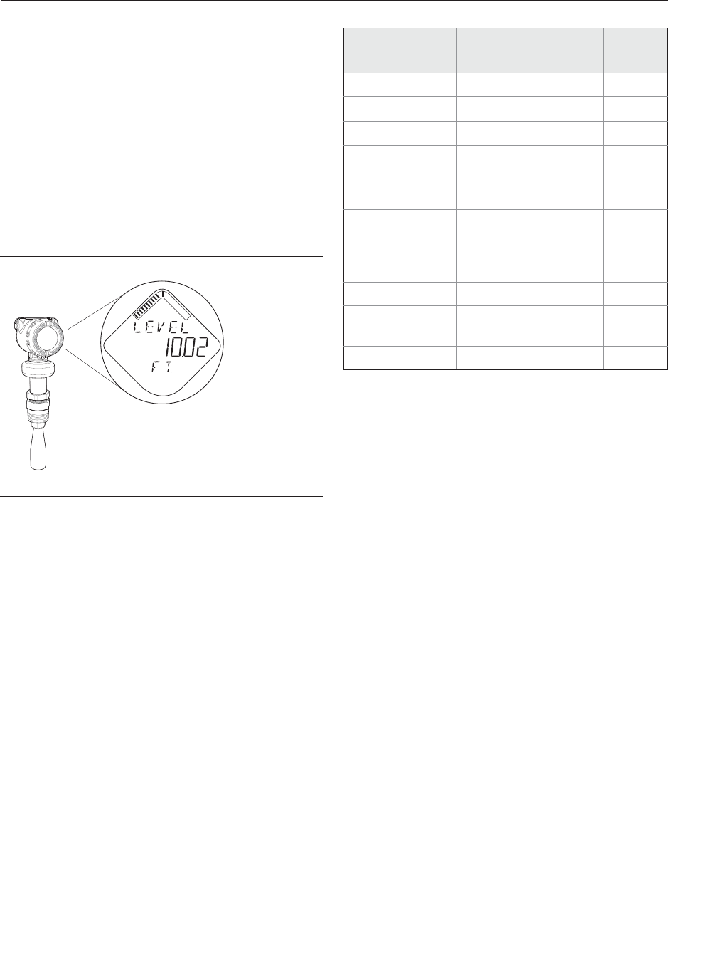
123
Specifications and Reference Data
Specifications and Reference Data
November 2016
Reference Manual
00809-0100-4408, Rev AA
PRELIMINARY
A.2.2 Display and configuration
Configuration tools
Rosemount Radar Master (running in Instrument
Inspector™)(1)
Device Descriptor (DD) based systems, e.g. AMS™ Device
Manager, 475 Field Communicator, and DeltaV™
Field Device Integration (FDI) based systems
Device display (option code M5)
Toggles between selected output variables
Shows diagnostic information (alerts)
Figure A-3. Device Display
Remote display
Data can be read remotely by using the Rosemount 751
Field Signal Indicator, see the Product Data Sheet for more
information.
Output variables
Output units
Level and distance: ft, in., m, cm, mm
Level rate: ft/s, in./min, in./s, m/h, m/s
Volume: ft3, in.3, yd3, US gal, imperial gal, barrel (bbl),
m3, l
Temperature: °F, °C
Signal strength: mV
Damping(2)
0 to 60 seconds (user selectable, default 2 seconds)
A.2.3 4-20 mA HART (output code H)
Output
Two-wire, 4-20 mA. Digital process variable is
superimposed on 4-20 mA signal, and available to any host
that conforms to the HART protocol. The HART signal can
be used in multidrop mode.
HART Revision
Revision 6 (default)
Revision 7 (option code HR7)
The HART revision can be switched in field.
1. Included in delivery of the transmitter.
Variable 4-20 mA Digital
output
Device
display
Level + + +
Distance (Ullage) + + +
Volume + + +
Scaled Variable(1)
1. Only for transmitters ordered with Smart Diagnostics Suite
(option code DA1)
+++
Electronics
Temperature -++
Signal Quality(1) -++
Level Rate - + +
Signal strength - + +
Percent of Range - + +
Percent of Range
Auxiliary -++
User Defined(1) +++
+ Available
- Not available
2. The Damping parameter defines how fast the device responds to
level changes (step response). A high value makes the level steady
but the device reacts slowly to level changes in the tank.
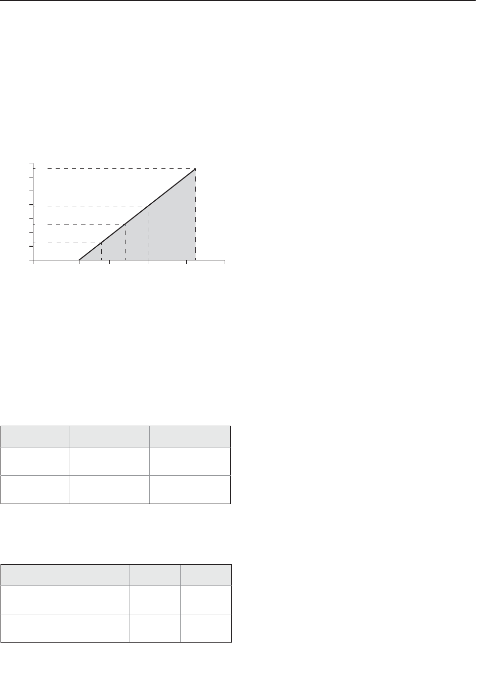
Specifications and Reference Data
November 2016
Reference Manual
00809-0100-4408, Rev AA
124 Specifications and Reference Data
PRELIMINARY
Power supply
Transmitter operates on 12-42.4 Vdc transmitter terminal
voltage (12-30 Vdc in Intrinsically Safe installations).
Power consumption
Max. 1 W, current max. 23 mA
Load limitations
Maximum loop resistance is determined by the voltage
level of the external power supply, as described by:
Maximum Loop Resistance = 43.5 * (External Power Supply Voltage - 12)
For HART communication, a minimum loop resistance of
250 : is required.
Signal wiring
24-14 AWG(1)
Analog signal on alarm
The transmitter automatically and continuously performs
self-diagnostic routines. If a failure or a measurement error
is detected, the analog signal will be driven offscale to alert
the user. High or low failure mode is user-configurable.
Analog saturation levels
The transmitter will drive the output to high or low
saturation values if measurement goes outside the 4-20 mA
range values.
A.2.4 Diagnostics
Alerts
The Rosemount 5408 and 5408:SIS are compliant to the
NAMUR NE 107 Field Diagnostics for standardized device
diagnostic information.
Tools and logging in Rosemount Radar Master
Echo curve
Alert and measurement log
The Rosemount Radar Master software enables easy and
powerful troubleshooting with the echo curve tool.
When connected to Rosemount Radar Master, past
measurement records (level and echo curves) as well as the
50 last event alerts are transferred from the transmitter’s
internal memory to your local computer. Historical data is
then presented in a graphical time line, enabling you to
thoroughly understand unexpected and intermittent
measurement behaviors or triggered alerts.
Smart Diagnostics Suite (option code DA1)
Signal Quality Metrics - Diagnostics package that monitors
the relations between surface, noise and threshold. The
function can be used to detect abnormal conditions in the
process such as antenna contamination or sudden loss of
signal strength. Signal Quality is available as output variable
and it comes with user configurable alerts.
Power Advisory - The transmitter automatically measures
and monitors the input voltage. If the voltage is too low,
operators will be provided with an early alert.
Scaled Variable - The scaled variable configuration allows
the user to convert a transmitter variable into an alternative
measurement, such as flow, mass or calibrated level (e.g. 5
point verification).
User Defined Variable - Allows designating any input
register in the device as output variable.
1. Twisted pairs and shielded wiring are recommended for environ-
ments with high EMI (electromagnetic interference).
High Low
Rosemount
standard
21.75 mA
(default)
3.75 mA
(option code C8)
NAMUR NE43 22.50 mA
(option code C4)
3.6 mA
(option code C5)
High Low
Rosemount standard
(default and option code C8) 20.8 mA 3.9 mA
NAMUR NE43
(option code C4 and C5) 20.5 mA 3.8 mA
42.4
2417.8
12
0
400
200
1000
800
600
1200
1400
20 30 40 50
521
250
782
1322
External Power Supply Voltage (Vdc)
Loop Resistance (Ohms)
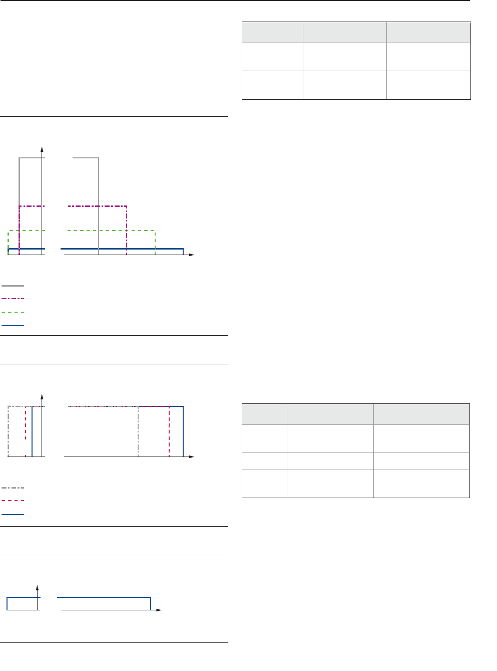
125
Specifications and Reference Data
Specifications and Reference Data
November 2016
Reference Manual
00809-0100-4408, Rev AA
PRELIMINARY
A.2.5 Process temperature and pressure
rating
The following figures give the maximum process
temperature (measured at the lower part of the flange or
threaded connection) and pressure rating for different
antenna types.
Final rating may be lower depending on flange selection.
Figure A-4. Cone Antenna (PTFE Seal)
Figure A-5. Cone Antenna (PEEK Seal)
Figure A-6. Parabolic Antenna
A.2.6 Temperature limits
Temperature limits may be further restricted by hazardous
area approvals, see “Product Certifications” on page 145.
A.2.7 Process sealing for flammable fluids
The bottom of the transmitter head is approved as a SINGLE
SEAL device, according to ANSI/ISA 12.27.01, up to a
process pressure of 160 bar.
Materials of the seal
Stainless Steel 316L and Glass
A.2.8 Flange rating
ASME
316 SST flanges according to ASME B16.5 Table 2-2.2
EN
1.4404 according to EN 1092-1 material group 13E0
JIS
TBD
Conditions used for flange strength calculations
1450 (100)
482
(250)
392
(200)
302
(150)
212
(100)
-40
(-40)
32
(0)
-76
(-60)
-15 (-1)
44 (3)
725 (50)
363 (25)
Code CAC
Code CAB
Code CAA
Code CAD
Pressure psig (bar)
Flange
temp.
°F (°C)
482
(250)
437
(225)
338
(170)
-76
(-60)
5
(-15)
32
(0)
-13
(-25)
-15 (-1)
754 (52)
Pressure psig (bar)
Flange
temp.
°F (°C)
Code CBF (FVMQ)
Code CBM (FKM)
Code CBK (Kalrez 6375)
392
(200)
-67
(-55)
32
(0)
-7 (-0.5)
43 (3)
Pressure psig (bar)
Flange
temperature
°F (°C)
Operating limit Storage limit(1)
1. The minimum storage temperature is -22 °F (-30 °C) for the cone
antenna with Kalrez 6375 O-ring (antenna type code CBK).
Without LCD
display TBD TBD
With LCD
display(2)
2. LCD display may not be readable and LCD display updates will be
slower at temperatures below -4 °F (-20 °C).
TBD TBD
ASME EN, JIS
Bolting
material TBD TBD
Gasket TBD TBD
Flange
material TBD TBD
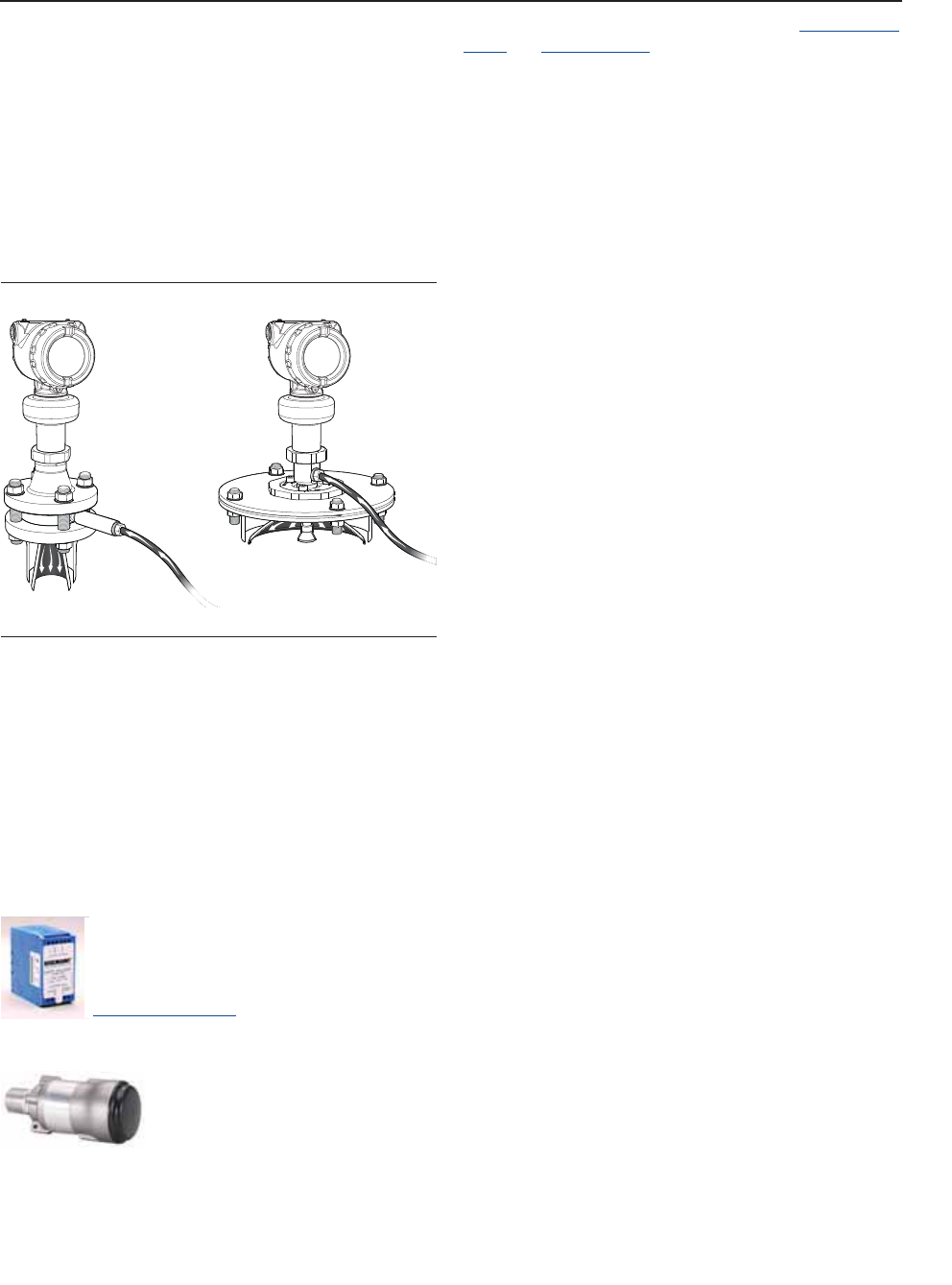
Specifications and Reference Data
November 2016
Reference Manual
00809-0100-4408, Rev AA
126 Specifications and Reference Data
PRELIMINARY
A.2.9 Air purging
An air purge connection can prevent clogging of the
antenna in extremely dusty applications. The easiest way to
determine if air purging is needed, is to open the manhole
hatch and see if there is a thick layer of dust/condensation
on it. If so, air purging is most likely needed. Typical media
to use is air.
All parabolic antennas come with an integrated air purge
connection. A separate air purge ring is available for cone
antennas with flanged connection (select option code PC1).
Figure A-7. Air Purging
Incoming air supply specification
Maximum pressure: 190 psi (13 bar)
Recommended pressure: 100 to 115 psi (7 to 8 bar)
Inlet/outlet connection: G 3/8-in.
Air consumption: 252 gal/min at 65 psi (955 l/min at 4.5
bar)
A.2.10 System integration
HART Tri-Loop™
By sending the digital HART signal to the
optional HART Tri-Loop, it is possible to have
up to three additional 4–20 mA analog signals.
See the Rosemount 333 HART Tri-Loop
Product Data Sheet for additional information.
Emerson Wireless 775 THUM™ Adapter
The optional Emerson Wireless 775
THUM Adapter can be mounted
directly on the transmitter or by
using a remote mounting kit.
IEC 62591 (WirelessHART®) enables access to multivariable
data and diagnostics, and adds wireless to almost any
measurement point.
See the Emerson Wireless 775 THUM Adapter Product Data
Sheet and Technical Note for additional information.
A.3 Physical specifications
A.3.1 Material selection
Emerson provides a variety of Rosemount product with
various product options and configurations including
materials of construction that can be expected to perform
well in a wide range of applications. The Rosemount
product information presented is intended as a guide for
the purchaser to make an appropriate selection for the
application. It is the purchaser’s sole responsibility to make
a careful analysis of all process parameters (such as all
chemical components, temperature, pressure, flow rate,
abrasives, contaminants, etc.), when specifying product,
materials, options and components for the particular
application. Emerson is not in a position to evaluate or
guarantee the compatibility of the process fluid or other
process parameters with the product, options,
configuration or materials of construction selected.

127
Specifications and Reference Data
Specifications and Reference Data
November 2016
Reference Manual
00809-0100-4408, Rev AA
PRELIMINARY
A.3.2 Engineered solutions
When standard model codes are not sufficient to fulfill
requirements, please consult the factory to explore
possible Engineered Solutions. This is typically, but not
exclusively, related to the choice of wetted materials or the
design of a process connection. These Engineered Solutions
are part of the expanded offerings and may be subject to
additional delivery lead time. For ordering, factory will
supply a special P-labeled numeric option code that should
be added at the end of the standard model string.
See example model string below.
Example Model String:
5408 A 1 S H A 1 E5 1 F 3 AB CAA 3 M5 DA1 P1234
A.3.3 Housing and enclosure
Electrical connections
Two cable/conduit entries (½-14 NPT, M20 x 1.5 or G1/2)
Optional adapters: M12 4-pin male eurofast® connector or
A size Mini 4-pin male minifast® connector
Materials
Electronics housing: Polyurethane-covered Aluminum or
Stainless Steel Grade CF-8M (ASTM A743)
Sensor module: 316L Stainless Steel
Ingress protection
IP 66/67/68(1) and NEMA® 4X
A.3.4 Tank connection
The tank connection consists of a tank seal, a flange, NPT
thread or BSPP (G) threads, or a specific welded connection
with swivel feature for parabolic antenna.
A.3.5 Flange dimensions
Follows ASME B16.5, JIS B2220, and EN 1092-1 standards.
For more information, see “Standard flanges” on page 143.
A.3.6 Antenna versions
Cone antenna
Best choice for a broad range of applications, including
free-propagation and still pipe/chamber installations
Cone extensions are available (option code S1 and S2)
Parabolic antenna
Ideal for long measuring ranges
A.3.7 Material exposed to tank atmosphere
Cone antenna, PTFE seal
316 / 316L SST (EN 1.4404)
PTFE fluoropolymer
Cone antenna, PEEK seal
316 / 316L SST (EN 1.4404)
PEEK polyetheretherketone with PTFE fluoropolymer
filler
FVMQ flourosilicone, Kalrez® 6375 perfluoroelastomer or
FKM fluoroelastomer (O-ring)
Parabolic antenna
316 / 316 L SST (EN 1.4404)
PTFE fluoropolymer
FVMQ flourosilicone (O-ring)
1. The transmitter meets IP 68 at 9.8 ft (3 m) for 30 minutes.

Specifications and Reference Data
November 2016
Reference Manual
00809-0100-4408, Rev AA
128 Specifications and Reference Data
PRELIMINARY
A.3.8 Weights
Transmitter heads(1)
Aluminum housing: TBD
Stainless steel housing: TBD
Antennas
2-in. cone antenna: TBD
3-in. cone antenna: TBD
4-in. cone antenna: TBD
2-in. cone antenna with extension (code S1): TBD
3-in. cone antenna with extension (code S1): TBD
4-in. cone antenna with extension (code S1): TBD
Parabolic antenna: 3.2 lb (1.5 kg)
Process connections
1. Fully functional transmitter with sensor module, housing, terminal
block, and covers.
Item Weight in lb. (kg)
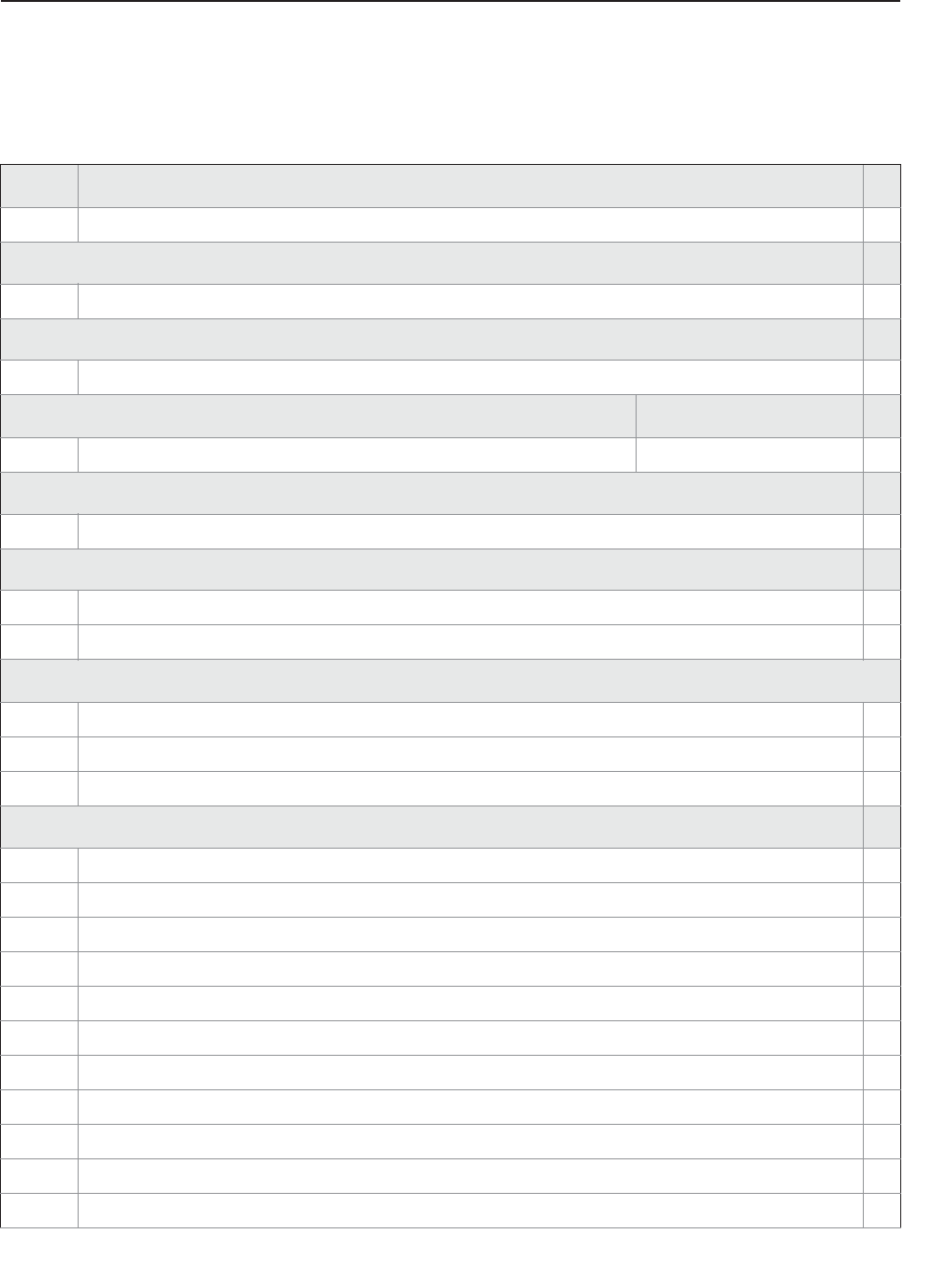
129
Specifications and Reference Data
Specifications and Reference Data
November 2016
Reference Manual
00809-0100-4408, Rev AA
PRELIMINARY
A.4 Ordering information
Table A-1. Rosemount 5408 Level Transmitter Ordering Information
The starred options (★) represent the most common options and should be selected for best delivery.
The non-starred offerings are subject to additional delivery lead time.
Model Product description
5408 Radar Level Transmitter ★
Profile
AStandard Monitoring & Control Applications ★
Measurement type
1Liquid Level Measurement ★
Performance class Range
SStandard Up to 130 ft (40 m) ★
Signal output
H4–20 mA with digital signal based on HART® Revision 6 protocol (HART Revision 7 available as option) ★
Housing material
AAluminum ★
SStainless Steel (SST) ★
Conduit/cable threads
11/2-14 NPT ★
2M20 x 1.5 ★
3(1) G1/2
Hazardous locations certifications
NA None ★
E1 ATEX Flameproof ★
I1 ATEX Intrinsic Safety ★
N1 ATEX Type n ★
E5 FM Explosion-proof, Dust Ignition-proof ★
I5 FM Intrinsically Safe; Nonincendive ★
E6 Canadian Explosion-proof, Dust Ignition-proof, Division 2 ★
I6 Canadian Intrinsically Safe ★
E7 IECEx Flameproof, Dust Ignition-proof ★
I7 IECEx Intrinsic Safety ★
N7 IECEx Type n ★

Specifications and Reference Data
November 2016
Reference Manual
00809-0100-4408, Rev AA
130 Specifications and Reference Data
PRELIMINARY
Materials of construction
1316 / 316L / EN 1.4404 ★
Process connection type Available antenna types
F(2) Flat Face Flange All ★
R(3) Raised Face Flange All ★
NNPT thread Cone Antenna ★
GBSPP (G) thread All ★
BBracket Mounting Cone Antenna ★
WWelded Connection Parabolic Antenna ★
Process connection size Available process connection types
A1½-in. Thread ★
22-in. / DN50 / 50A Flange, Thread ★
33-in. / DN80 / 80A Flange, Thread ★
B3½-in. Thread ★
44-in. / DN100 / 100A Flange, Thread ★
66-in. / DN150 / 150A Flange ★
88-in. / DN200 / 200A Flange ★
T10-in. / DN250 / 250A Flange ★
ZNone (use when ordering bracket mounting) Bracket Mounting ★
Process connection rating
ZZ For use with non-flange process connection type ★
ASME flanges (refer to Table A-3 and Table A-4 on page 139 for availability)
AA ASME B16.5 Class 150 ★
AB ASME B16.5 Class 300 ★
AC ASME B16.5 Class 600 ★
EN flanges (refer to Table A-3 and Table A-4 on page 139 for availability)
DK EN1092-1 PN6 ★
DA EN1092-1 PN16 ★
DB EN1092-1 PN40 ★
DC EN1092-1 PN63 ★
DD EN1092-1 PN100 ★
Table A-1. Rosemount 5408 Level Transmitter Ordering Information
The starred options (★) represent the most common options and should be selected for best delivery.
The non-starred offerings are subject to additional delivery lead time.

131
Specifications and Reference Data
Specifications and Reference Data
November 2016
Reference Manual
00809-0100-4408, Rev AA
PRELIMINARY
JIS flanges (refer to Table A-3 and Table A-4 on page 139 for availability)
JK JIS 5K ★
JA JIS 10K ★
JB JIS 20K ★
Antenna type Operating pressure Operating temperature
CAA Cone Antenna (PTFE seal) -15 to 363 psig (-1 to 25 bar) -76 to 392 °F (-60 to 200 °C) ★
CAB Cone Antenna (PTFE seal) -15 to 725 psig (-1 to 50 bar) -40 to 302 °F (-40 to 150 °C) ★
CAC Cone Antenna (PTFE seal) -15 to 1450 psig (-1 to 100 bar) -40 to 212 °F (-40 to 100 °C) ★
CAD Cone Antenna (PTFE seal) -15 to 44 psig (-1 to 3 bar) -76 to 482 °F (-60 to 250 °C) ★
CBF Cone Antenna (PEEK seal, FVMQ) -15 to 754 psig (-1 to 52 bar) -76 to 338 °F (-60 to 170 °C) ★
CBK Cone Antenna (PEEK seal, Kalrez®
6375) -15 to 754 psig (-1 to 52 bar) 5 to 482 °F (-15 to 250 °C) ★
CBM Cone Antenna (PEEK seal, FKM) -15 to 754 psig (-1 to 52 bar) -13 to 437 °F (-25 to 225 °C) ★
PAS Parabolic Antenna, Swivel Mount -7 to 43 psig (-0.5 to 3 bar) -67 to 392 °F (-55 to 200 °C) ★
Antenna size Available antenna types
22-in. (DN50) Cone Antenna ★
33-in. (DN80) Cone Antenna ★
44-in. (DN100) Cone Antenna ★
88-in. (DN200) Parabolic Antenna ★
Options (include with selected model number)
Antenna extensions Total length
S1 SST Cone Antenna Extension 24-in. (600 mm) ★
S2 SST Cone Antenna Extension segmented 48-in. (1200 mm) ★
Purging connection
PC1 Purging Connector (see page 126)★
Display
M5 LCD Display ★
Functional safety options
EF1 Ready for upgrade to Rosemount 5408:SIS ★
Diagnostic functionality
DA1 Smart Diagnostics Suite (see page 124)★
Table A-1. Rosemount 5408 Level Transmitter Ordering Information
The starred options (★) represent the most common options and should be selected for best delivery.
The non-starred offerings are subject to additional delivery lead time.

Specifications and Reference Data
November 2016
Reference Manual
00809-0100-4408, Rev AA
132 Specifications and Reference Data
PRELIMINARY
HART revision configuration
HR7 4-20 mA with digital signal based on HART Revision 7 protocol ★
Open air applications configuration
OA(4) Open Air Applications Configuration; LPR (Level Probing Radar) ★
Alarm limits
C4 NAMUR Alarm and Saturation Levels, High Alarm ★
C5 NAMUR Alarm and Saturation Levels, Low Alarm ★
C8(5) Standard Rosemount Alarm and Saturation Levels, Low Alarm ★
Welding standard for flanges
AW(6) According to ASME standard ★
EW(6) According to EN standard ★
Special quality assurance
Q4 Calibration Data Certificate ★
Hydrostatic testing
Q5(7) Hydrostatic Testing, including certificate ★
Quality traceability certification
Q8(8) Material Traceability Certification per EN 10204 (2.1/3.1 non metallic) ★
Materials certification
Q15 NACE® Material Recommendation per NACE MR0175/ISO 15156 ★
Q25 NACE Material Recommendation per ANSI/NACE MR0103/ISO 17495-1 ★
Q35 NACE Material Recommendation per NACE MR0175/ISO 15156 and/or ANSI/NACE MR0103/ISO 17495-1 ★
Canadian Registration Number (CRN)
Q17 CRN Approval Certificate ★
Welding procedure qualification record documentation
Q66(6) Welding Procedure Qualification Record Documentation (WPQR) ★
Q67(6) Welder Performance Qualification Record (WPQ) ★
Q68(6) Welding Procedure Specification (WPS) ★
Q79(6) WPQR/WPQ/WPS ★
Dye penetration test certificate
Q73(6) Certificate of Liquid Penetrant Inspection ★
Table A-1. Rosemount 5408 Level Transmitter Ordering Information
The starred options (★) represent the most common options and should be selected for best delivery.
The non-starred offerings are subject to additional delivery lead time.

133
Specifications and Reference Data
Specifications and Reference Data
November 2016
Reference Manual
00809-0100-4408, Rev AA
PRELIMINARY
Positive material identification certificate
Q76 Positive Material Identification Certificate of Conformance ★
Extended product warranty
WR3 3-year Limited Warranty ★
WR5 5-year Limited Warranty ★
Paint option for aluminum housing
PY1 Housing and Covers in Yellow ★
PY2 Covers in Yellow ★
PR1 Housing and Covers in Red ★
PR2 Covers in Red ★
PO1 Housing and Covers in Orange ★
PO2 Covers in Orange ★
Conduit electrical connector
EC(9) M 12, 4-pin, Male connector (eurofast®)★
MC(9) A size Mini, 4-pin, Male connector (minifast®)★
Adapter wetted parts
A1 Adapter for Rosemount 5402 Antennas ★
Specials (see page 127)
PXXXX Custom Engineered Solutions beyond standard model codes. Consult factory for details.
Typical model number: 5408 A 1 S H A 1 E5 1 R 3 AB CAB 3 M5 DA1
1. G1/2 thread form is not available with explosion-proof/flameproof approvals.
2. Type A flat face for EN 1092-1 flanges.
3. Type B1 raised face for EN 1092-1 flanges.
4. Not available with 2-in. or 3-in. cone antenna.
5. The standard alarm setting is high.
6. Only applies to flanged process connections with welded construction; only applicable to cone antennas (see Table A-3 on page 138).
7. Hydrostatic testing is only available for cone antennas with flanged process connections.
8. Certificate includes all pressure retaining wetted parts.
9. Requires 1/2-14 NPT conduit/cable threads (code 1). Available with Intrinsically Safe approvals only.
Table A-1. Rosemount 5408 Level Transmitter Ordering Information
The starred options (★) represent the most common options and should be selected for best delivery.
The non-starred offerings are subject to additional delivery lead time.

Specifications and Reference Data
November 2016
Reference Manual
00809-0100-4408, Rev AA
134 Specifications and Reference Data
PRELIMINARY
Table A-2. Rosemount 5408:SIS Level Transmitter Ordering Information
The starred options (★) represent the most common options and should be selected for best delivery.
The non-starred offerings are subject to additional delivery lead time.
Model Product description
5408 Radar Level Transmitter ★
Profile
FFunctional Safety / SIS Applications ★
Measurement type
1Liquid Level Measurement ★
Performance class Range
SStandard Up to 82 ft (25 m) ★
Signal output
H4–20 mA with digital signal based on HART Revision 6 protocol (HART Revision 7 available as option) ★
Housing material
AAluminum ★
SStainless Steel (SST) ★
Conduit/cable threads
11/2-14 NPT ★
2M20 x 1.5 ★
3(1) G1/2
Hazardous locations certifications
NA None ★
E1 ATEX Flameproof ★
I1 ATEX Intrinsic Safety ★
N1 ATEX Type n ★
E5 FM Explosion-proof, Dust Ignition-proof ★
I5 FM Intrinsically Safe; Nonincendive ★
E6 Canadian Explosion-proof, Dust Ignition-proof, Division 2 ★
I6 Canadian Intrinsically Safe ★
E7 IECEx Flameproof, Dust Ignition-proof ★
I7 IECEx Intrinsic Safety ★
N7 IECEx Type n ★
Materials of construction
1316 / 316L / EN 1.4404 ★

135
Specifications and Reference Data
Specifications and Reference Data
November 2016
Reference Manual
00809-0100-4408, Rev AA
PRELIMINARY
Process connection type Available antenna types
F(2) Flat Face Flange All ★
R(3) Raised Face Flange All ★
NNPT thread Cone Antenna ★
GBSPP (G) thread All ★
BBracket Mounting Cone Antenna ★
WWelded Connection Parabolic Antenna ★
Process connection size Available process connection types
A1½-in. Thread ★
22-in. / DN50 / 50A Flange, Thread ★
33-in. / DN80 / 80A Flange, Thread ★
B3½-in. Thread ★
44-in. / DN100 / 100A Flange, Thread ★
66-in. / DN150 / 150A Flange ★
88-in. / DN200 / 200A Flange ★
T10-in. / DN250 / 250A Flange ★
ZNone (use when ordering bracket mounting) Bracket Mounting ★
Process connection rating
ZZ For use with non-flange process connection type ★
ASME flanges (refer to Table A-3 and Table A-4 on page 139 for availability)
AA ASME B16.5 Class 150 ★
AB ASME B16.5 Class 300 ★
AC ASME B16.5 Class 600 ★
EN flanges (refer to Table A-3 and Table A-4 on page 139 for availability)
DK EN1092-1 PN6 ★
DA EN1092-1 PN16 ★
DB EN1092-1 PN40 ★
DC EN1092-1 PN63 ★
DD EN1092-1 PN100 ★
JIS flanges (refer to Table A-3 and Table A-4 on page 139 for availability)
JK JIS 5K ★
JA JIS 10K ★
JB JIS 20K ★
Table A-2. Rosemount 5408:SIS Level Transmitter Ordering Information
The starred options (★) represent the most common options and should be selected for best delivery.
The non-starred offerings are subject to additional delivery lead time.

Specifications and Reference Data
November 2016
Reference Manual
00809-0100-4408, Rev AA
136 Specifications and Reference Data
PRELIMINARY
Antenna type Operating pressure Operating temperature
CAA Cone Antenna (PTFE seal) -15 to 363 psig (-1 to 25 bar) -76 to 392 °F (-60 to 200 °C) ★
CAB Cone Antenna (PTFE seal) -15 to 725 psig (-1 to 50 bar) -40 to 302 °F (-40 to 150 °C) ★
CAC Cone Antenna (PTFE seal) -15 to 1450 psig (-1 to 100 bar) -40 to 212 °F (-40 to 100 °C) ★
CAD Cone Antenna (PTFE seal) -15 to 44 psig (-1 to 3 bar) -76 to 482 °F (-60 to 250 °C) ★
CBF Cone Antenna (PEEK seal, FVMQ) -15 to 754 psig (-1 to 52 bar) -76 to 338 °F (-60 to 170 °C) ★
CBK Cone Antenna (PEEK seal, Kalrez
6375) -15 to 754 psig (-1 to 52 bar) 5 to 482 °F (-15 to 250 °C) ★
CBM Cone Antenna (PEEK seal, FKM) -15 to 754 psig (-1 to 52 bar) -13 to 437 °F (-25 to 225 °C) ★
PAS Parabolic Antenna, Swivel Mount -7 to 43 psig (-0.5 to 3 bar) -67 to 392 °F (-55 to 200 °C) ★
Antenna size Available antenna types
22-in. (DN50) Cone Antenna ★
33-in. (DN80) Cone Antenna ★
44-in. (DN100) Cone Antenna ★
88-in. (DN200) Parabolic Antenna ★
Options (include with selected model number)
Antenna extensions Total length
S1 SST Cone Antenna Extension 24-in. (600 mm) ★
S2 SST Cone Antenna Extension segmented 48-in. (1200 mm) ★
Purging connection
PC1 Purging Connector (see page 126)★
Display
M5 LCD Display ★
Functional safety options
EF2 Extended SIS Package ★
Diagnostic functionality
DA1 Smart Diagnostics Suite (see page 124)★
HART revision configuration
HR7 4-20 mA with digital signal based on HART Revision 7 protocol ★
Open air applications configuration
OA(4) Open Air Applications Configuration; LPR (Level Probing Radar) ★
Table A-2. Rosemount 5408:SIS Level Transmitter Ordering Information
The starred options (★) represent the most common options and should be selected for best delivery.
The non-starred offerings are subject to additional delivery lead time.

137
Specifications and Reference Data
Specifications and Reference Data
November 2016
Reference Manual
00809-0100-4408, Rev AA
PRELIMINARY
Alarm limits
C4 NAMUR Alarm and Saturation Levels, High Alarm ★
C5 NAMUR Alarm and Saturation Levels, Low Alarm ★
C8(5) Standard Rosemount Alarm and Saturation Levels, Low Alarm ★
Welding standard for flanges
AW(6) According to ASME standard ★
EW(6) According to EN standard ★
Special quality assurance
Q4 Calibration Data Certificate ★
Hydrostatic testing
Q5(7) Hydrostatic Testing, including certificate ★
Quality traceability certification
Q8(8) Material Traceability Certification per EN 10204 (2.1/3.1 non metallic) ★
Quality certification for safety
QS Prior-use certificate of FMEDA Data ★
QT Safety-certified to IEC 61508 with certificate of FMEDA data ★
Materials certification
Q15 NACE Material Recommendation per NACE MR0175/ISO 15156 ★
Q25 NACE Material Recommendation per ANSI/NACE MR0103/ISO 17495-1 ★
Q35 NACE Material Recommendation per NACE MR0175/ISO 15156 and/or ANSI/NACE MR0103/ISO 17495-1 ★
Canadian Registration Number (CRN)
Q17 CRN Approval Certificate ★
Welding procedure qualification record documentation
Q66(6) Welding Procedure Qualification Record Documentation (WPQR) ★
Q67(6) Welder Performance Qualification Record (WPQ) ★
Q68(6) Welding Procedure Specification (WPS) ★
Q79(6) WPQR/WPQ/WPS ★
Dye penetration test certificate
Q73(6) Certificate of Liquid Penetrant Inspection ★
Positive material identification certificate
Q76 Positive Material Identification Certificate of Conformance ★
Table A-2. Rosemount 5408:SIS Level Transmitter Ordering Information
The starred options (★) represent the most common options and should be selected for best delivery.
The non-starred offerings are subject to additional delivery lead time.
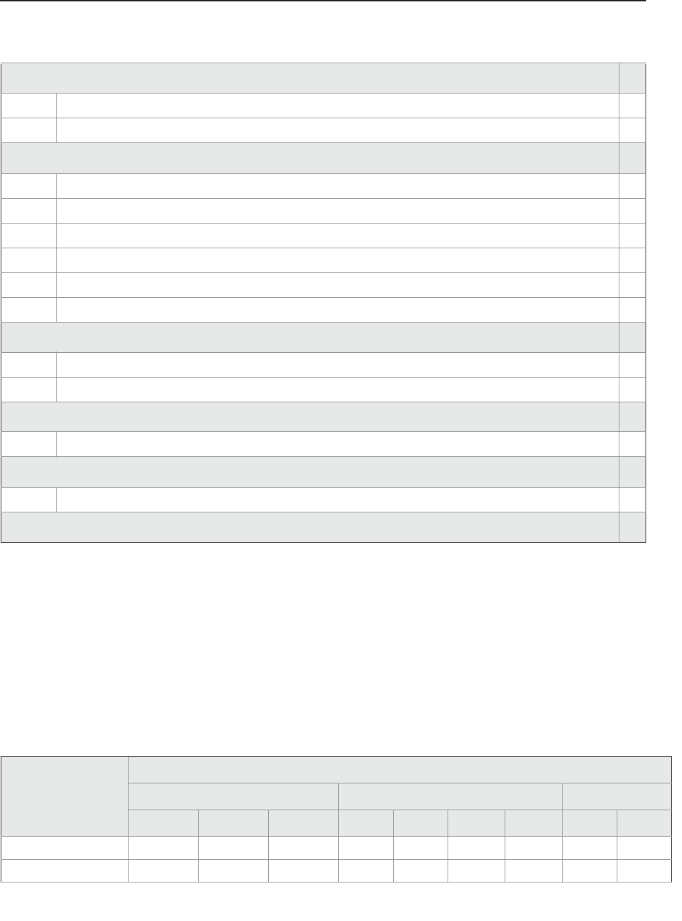
Specifications and Reference Data
November 2016
Reference Manual
00809-0100-4408, Rev AA
138 Specifications and Reference Data
PRELIMINARY
Extended product warranty
WR3 3-year Limited Warranty ★
WR5 5-year Limited Warranty ★
Paint option for aluminum housing
PY1 Housing and Covers in Yellow ★
PY2 Covers in Yellow ★
PR1 Housing and Covers in Red ★
PR2 Covers in Red ★
PO1 Housing and Covers in Orange ★
PO2 Covers in Orange ★
Conduit electrical connector
EC(9) M 12, 4-pin, Male connector (eurofast®)★
MC(9) A size Mini, 4-pin, Male connector (minifast®)★
Adapter wetted parts
A1 Adapter for Rosemount 5402 Antennas ★
Specials (see page 127)
PXXXX Custom Engineered Solutions beyond standard model codes. Consult factory for details.
Typical model number: 5408 F 1 S H A 1 E5 1 R 3 AB CAB 3 M5 DA1 EF2 QT
1. G1/2 thread form is not available with explosion-proof/flameproof approvals.
2. Type A flat face for EN 1092-1 flanges.
3. Type B1 raised face for EN 1092-1 flanges.
4. Not available with 2-in. or 3-in. cone antenna.
5. The standard alarm setting is high.
6. Only applies to flanged process connections with welded construction; only applicable to cone antennas (see Table A-3 on page 138).
7. Hydrostatic testing is only available for cone antennas with flanged process connections.
8. Certificate includes all pressure retaining wetted parts.
9. Requires 1/2-14 NPT conduit/cable threads (code 1). Available with Intrinsically Safe approvals only.
Table A-3. Cone Antenna - Availability of Flanged Process Connections (Type(1) vs. Size and Rating)
Process connection
size
Process connection rating
ASME B16.5 flanges EN1092-1 flanges JIS B2220 flanges
Class 150(2) Class 300(2) Class 600(3) PN16(4) PN40(4) PN63(3) PN100(3) 10K(2) 20K(3)
2-in. / DN50 / 50A R R R F F, R F, R F R R
3-in. / DN80 / 80A R R R F, R F, R F, R F, R R R
Table A-2. Rosemount 5408:SIS Level Transmitter Ordering Information
The starred options (★) represent the most common options and should be selected for best delivery.
The non-starred offerings are subject to additional delivery lead time.
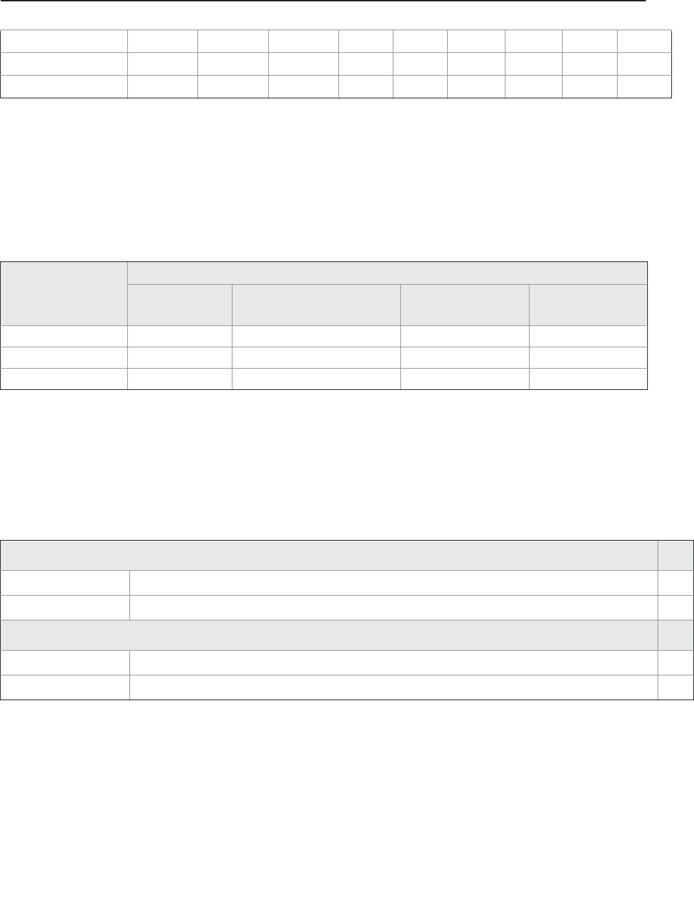
139
Specifications and Reference Data
Specifications and Reference Data
November 2016
Reference Manual
00809-0100-4408, Rev AA
PRELIMINARY
4-in. / DN100 / 100A R R N/A F, R F, R F F R R
6-in. / DN150 / 150A R R N/A F, R F, R N/A N/A R R
8-in. / DN200 / 200A R R N/A F, R F, R N/A N/A R N/A
1. F = Flat Face (process connection type code F)
G = BSPP (G) thread (process connection type code G)
N = NPT thread (process connection type code N)
R = Raised Face (process connection type code R)
2. Forged one-piece flange (see page 143)
3. Welded construction (see page 143)
4. Welded construction for type A flat face; forged one-piece flange for type B1 raised face.
Table A-4. Parabolic Antenna - Availability of Process Connections (Type(1) vs. Size and Rating)
1. F = Flat Face face (process connection type code F)
G = BSPP (G) thread (process connection type code G)
R = Raised Face face (process connection type code R)
W = Welded connection (process connection type code W)
Process connection
size
Process connection rating
Threaded/welded
connection ASME B16.5 Class 150 flange EN1092-1 PN6 flange JIS B2220 5K flange
3½-in. G, W N/A N/A N/A
8-in. / DN200 / 200A N/A R F R
10-in. / DN250 / 250A N/A R F R
Table A-5. Accessories
The starred options (★) represent the most common options and should be selected for best delivery.
The non-starred offerings are subject to additional delivery lead time.
HART modem and cable
03300-7004-0001 MACTek® VIATOR® HART modem and cables (RS-232 connection) ★
03300-7004-0002 MACTek VIATOR HART modem and cables (USB connection) ★
Parabolic antenna accessories (see page 141)
05400-1200-0001 Purge plug kit (blind plug and bonded seal) TBD
05400-1200-0002 Lock nut G 3½-in. (for parabolic antenna with threaded connection) TBD
Table A-3. Cone Antenna - Availability of Flanged Process Connections (Type(1) vs. Size and Rating)
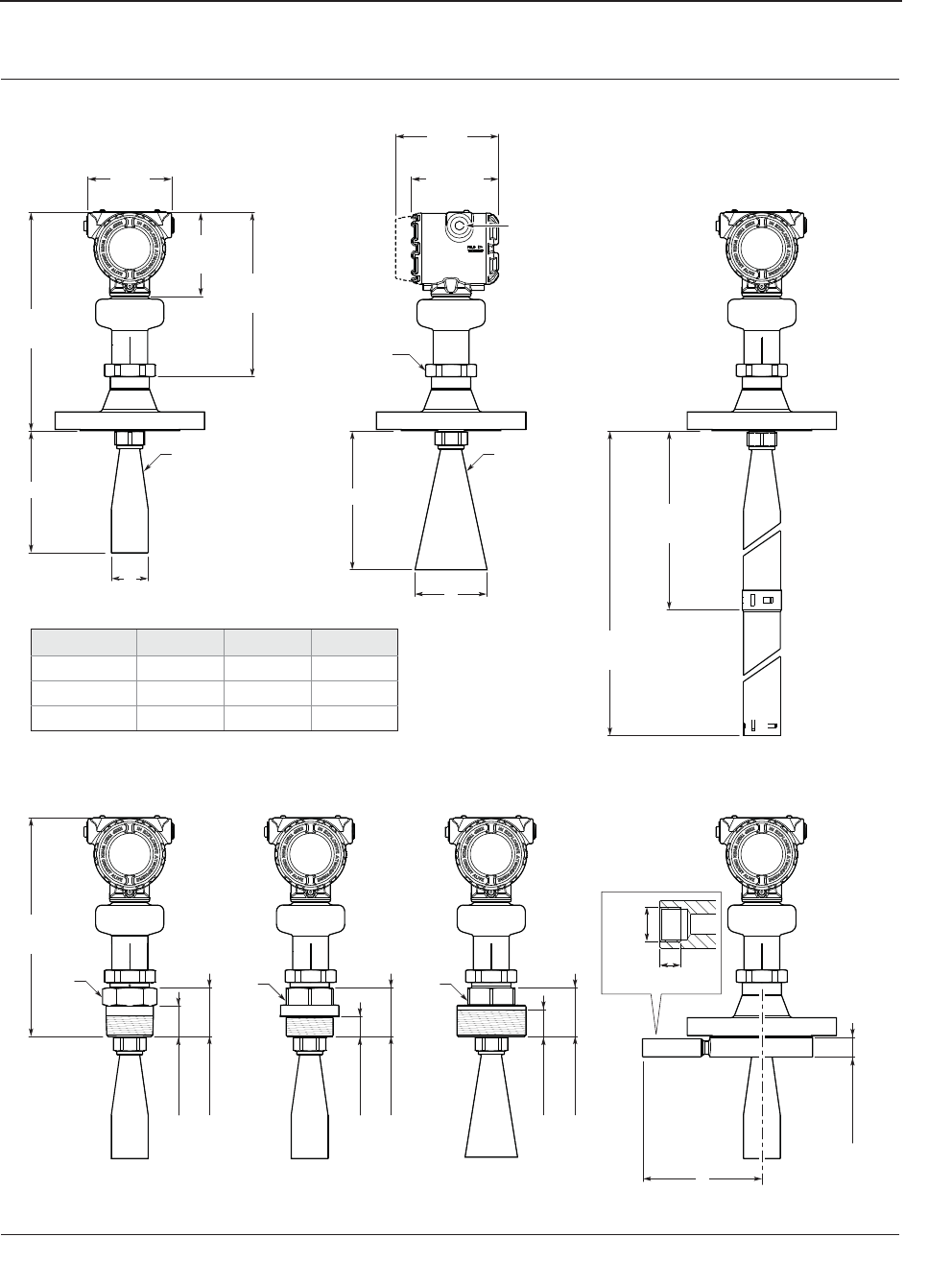
Specifications and Reference Data
November 2016
Reference Manual
00809-0100-4408, Rev AA
140 Specifications and Reference Data
PRELIMINARY
A.5 Dimensional drawings
Figure A-8. Cone Antenna
Dimensions are in inches (millimeters).
4.21
(106.9)
8.27
(210)
4.21
(107)
4.51
(114.5)
5.16
(131)
11.02
(280)
11.02
(280)
AA
s60 s60 s60
s60
B
L
B
1.57 (40)
2.44 (62)
1.06 (27)
2.44 (62)
G3/8
0.39 (10)
1.34 (34)
1.00 (25.5)
2.44 (62)
½-14 NPT,
M20 x 1.5 or G1/2
Optional adapters:
eurofast and minifast
Cone size A B L
2-in. (DN50) 6.10 (155) 1.85 (47) 5.39 (137)
3-in. (DN80) 6.02 (153) 2.64 (67) 6.77 (172)
4-in. (DN100) 6.93 (176) 3.62 (92) 7.80 (198)
2" cone style 3", 4" cone style
Purging connector
(option code PC1)
Extended cone antenna
NPT 1.5", 2", 3", 4" BSPP (G) 1.5", 2" BSPP (G) 3", 4"
Option code S1
23.6 (600)
Option code S2
47.2 (1200)
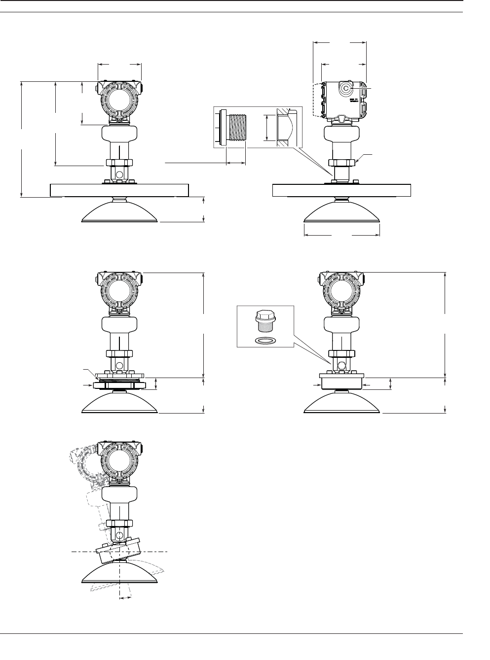
141
Specifications and Reference Data
Specifications and Reference Data
November 2016
Reference Manual
00809-0100-4408, Rev AA
PRELIMINARY
Figure A-9. Parabolic Antenna
Dimensions are in inches (millimeters).
4.21
(106.9)
8.27
(210)
4.21
(107)
7.40
(188)
4.51
(114.5)
5.16
(131)
2.46 (62.4)
10.35
(263)
1.14 (29)
1.14 (29)
10.35
(263)
3.43
(87)
3.43
(87)
Ø 3.90(99)
11.34
(288)
±15°
s60
0.3-0.4 (8-10)
½-14 NPT, M20 x 1.5
or G1/2
Optional adapters:
eurofast and minifast
Purging connector
(option code PC1)
BSPG 3.5"
Threaded connection Welded connection
G3/8"
(gasket excluded)
Lock nut (accessory)
P/N 05400-1200-0002
Purge plug kit (accessory)
P/N 05400-1200-0001
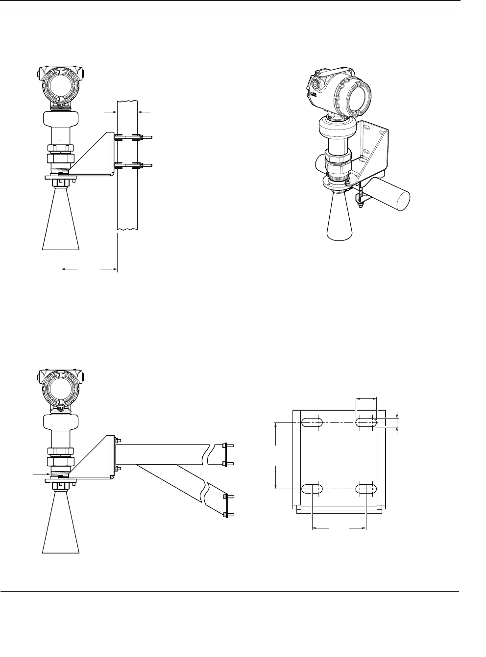
Specifications and Reference Data
November 2016
Reference Manual
00809-0100-4408, Rev AA
142 Specifications and Reference Data
PRELIMINARY
Figure A-10. Bracket Mounting (Process Connection Type Code B)
Dimensions are in inches (millimeters).
NPT 1.5"
5.60
(142)
2.24
(57)
0.35 (9)
0.87 (22)
2.76
(70)
Pipe mounting
(vertical pipe)
Pipe mounting
(horizontal pipe)
Wall mounting
Pipe diameter,
max 2.52 in. (64 mm)
Hole pattern for wall mounting
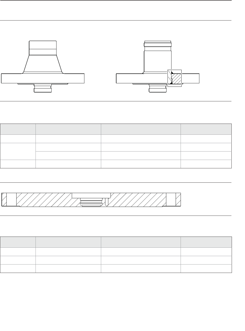
143
Specifications and Reference Data
Specifications and Reference Data
November 2016
Reference Manual
00809-0100-4408, Rev AA
PRELIMINARY
A.6 Standard flanges
Figure A-11. Cone Antenna
Table A-6. Standard Flanges for Cone Antenna
Figure A-12. Parabolic antenna
Table A-7. Standard Flanges for Parabolic Antenna
Forged one-piece Welded construction
Standard Face type(1) Face surface finish, RaMaterial
ASME B16.5 Raised face 125-250 μin 316 / 316L
EN 1092-1 Type B1 raised face 3.2-12.5 μm EN 1.4404
Type A flat face 3.2-12.5 μm EN 1.4404
JIS B2220 Raised face 3.2-6.3 μm EN 1.4404
1. Face gasket surface is serrated per mating standard.
Standard Face type(1)
1. Face gasket surface is serrated per mating standard.
Face surface finish Material
ASME B16.5 Raised face, TBD in. 125-250 μin 316 / 316L
EN 1092-1 Type A flat face 3.2-12.5 μm EN 1.4404
JIS B2220 Raised face, TBD mm 3.2-12.5 μm EN 1.4404

Specifications and Reference Data
November 2016
Reference Manual
00809-0100-4408, Rev AA
144 Specifications and Reference Data
PRELIMINARY

145
Product Certifications
Product Certifications
November 2016
Reference Manual
00809-0100-4408, Rev AA
PRELIMINARY
Appendix B Product Certifications
Rev 0.88
European Directive Information . . . . . . . . . . . . . . . . . . . . . . . . . . . . . . . . . . . . . . . . . . . . page 145
Telecommunication compliance . . . . . . . . . . . . . . . . . . . . . . . . . . . . . . . . . . . . . . . . . . . page 145
FCC . . . . . . . . . . . . . . . . . . . . . . . . . . . . . . . . . . . . . . . . . . . . . . . . . . . . . . . . . . . . . . . . . . . . page 145
IC . . . . . . . . . . . . . . . . . . . . . . . . . . . . . . . . . . . . . . . . . . . . . . . . . . . . . . . . . . . . . . . . . . . . . . page 145
Radio Equipment Directive (RED) 2014/53/EU . . . . . . . . . . . . . . . . . . . . . . . . . . . . . . . page 146
Installing Equipment in North America . . . . . . . . . . . . . . . . . . . . . . . . . . . . . . . . . . . . . . page 146
USA . . . . . . . . . . . . . . . . . . . . . . . . . . . . . . . . . . . . . . . . . . . . . . . . . . . . . . . . . . . . . . . . . . . . page 146
Canada . . . . . . . . . . . . . . . . . . . . . . . . . . . . . . . . . . . . . . . . . . . . . . . . . . . . . . . . . . . . . . . . . page 148
Europe . . . . . . . . . . . . . . . . . . . . . . . . . . . . . . . . . . . . . . . . . . . . . . . . . . . . . . . . . . . . . . . . . . page 150
International . . . . . . . . . . . . . . . . . . . . . . . . . . . . . . . . . . . . . . . . . . . . . . . . . . . . . . . . . . . . page 152
Approval drawings . . . . . . . . . . . . . . . . . . . . . . . . . . . . . . . . . . . . . . . . . . . . . . . . . . . . . . . page 153
B.1 European Directive Information
A copy of the EU Declaration of Conformity can be found at
the end of the Product Certifications document. The most
recent revision of the EU Declaration of Conformity can be
found at EmersonProcess.com/Rosemount.
B.2 Telecommunication
compliance
Measurement principle
Frequency Modulated Continuous Wave (FMCW), 26 GHz
Maximum output power
-5 dBm (0.32 mW)
Frequency range
24.05 to 27.0 GHz (TLPR)
24.05 to 26.5 GHz (LPR)
LPR (Level Probing Radar) equipment are devices for
measurement of level in the open air or in a closed space.
Model option “OA”.
TLPR (Tank Level Probing Radar) equipment are devices
for measurement of level in a closed space only (i.e metallic
or concrete tanks).
B.3 FCC
Note: This equipment has been tested and found to comply
with the limits for a Class B digital device, pursuant to part
15 of the FCC Rules. These limits are designed to provide
reasonable protection against harmful interference in a
residential installation. This equipment generates, uses and
can radiate radio frequency energy and, if not installed and
used in accordance with the instructions, may cause
harmful interference to radio communications. However,
there is no guarantee that interference will not occur in a
particular installation. If this equipment does cause harmful
interference to radio or television reception, which can be
determined by turning the equipment off and on, the user
is encouraged to try to correct the interference by one or
more of the following measures:
Reorient or relocate the receiving antenna.
Increase the separation between the equipment and
receiver.
Connect the equipment into an outlet on a circuit
different from that to which the receiver is connected.
Consult the dealer or an experienced radio/TV technician
for help.
FCC ID: K8C5408L (for LPR)
K8C5408T (for TLPR)
B.4 IC
This device complies with Industry Canada’s
licence-exempt RSS standard. Operation is subject to the
following conditions:
1) This device may not cause interference.
2) This device must accept any interference received,
including interference that may cause undesired operation.

Product Certifications
November 2016
Reference Manual
00809-0100-4408, Rev AA
146 Product Certifications
PRELIMINARY
3) The installation of the LPR/TLPR device shall be done by
trained installers in strict compliance with the
manufacturer’s instructions.
4) The use of this device is on a “no-interference,
no-protection” basis. That is, the user shall accept
operations of high-powered radar in the same frequency
band which may interfere with or damage this device.
However, devices found to interfere with primary licensing
operations will be required to be removed at the user’s
expense.
5) Devices operating under TLPR conditions (i.e. not
operating in “Open Air” Mode) shall be installed and
operated in a completely enclosed container to prevent RF
emissions, which can otherwise interfere with aeronautical
navigation.
Le présent appareil est conforme aux CNR d'Industrie
Canada applicables aux appareils radio exempts de licence.
L'exploitation est autorisée aux conditions suivantes:
1) l'appareil ne doit pas produire de brouillage.
2) l'utilisateur de l'appareil doit accepter tout brouillage
radioélectrique subi, même si le brouillage est susceptible
d'en compromettre le fonctionnement.
3) L’installation d’un dispositif LPR ou TLPR doit être
effectuée par des installateurs qualifiés, en pleine
conformité avec les instructions du fabricant.
4) Ce dispositif ne peut être exploité qu'en régime de
non-brouillage et de non-protection, c'est-à-dire que
l'utilisateur doit accepter que des radars de haute puissance
de la même bande de fréquences puissent brouiller ce
dispositif ou même l'endommager. D'autre part, les
capteurs de niveau qui perturbent une exploitation
autorisée par licence de fonctionnement principal doivent
être enlevés aux frais de leur utilisateur.
5) Un dispositif visé comme TLPR (“Open Air”) doit être
installé et exploité dans un réservoir entièrement fermé afin
de prévenir les rayonnements RF qui pourraient autrement
perturber la navigation aéronautique.
Certificate: 2827A-5408L (for LPR)
2827A-5408T (for TLPR)
B.5 Radio Equipment Directive
(RED) 2014/53/EU
This device complies with ETSI EN 302 372 (TLPR), ETSI EN
302 729 (LPR) and EN 62479.
For the receiver test that covers the influence of an
interferer signal to the device, the performance criterion
has at least the following level of performance according to
ETSI TS 103 361 [6].
Performance criterion: measurement value variation ǻd
over time during a distance measurement
Level of performance: ǻd +/- 2 mm
LPR (Level Probing Radar), model code “OA”
Install at a separation distance of >4 km from Radio
Astronomy sites, unless a special authorization has been
provided by the responsible National regulatory authority
(a list of Radio Astronomy sites may be found at
www.craf.eu).
Between 4 km to 40 km around any Radio Astronomy site
the LPR antenna height shall not exceed 15 m height above
ground.
TLPR (Tank Level Probing Radar)
The device must be installed in closed tanks. Install
according to requirements in ETSI EN 302 372 (Annex E).
B.6 Installing Equipment in North
America
The US National Electrical Code (NEC) and the Canadian
Electrical Code (CEC) permit the use of Division marked
equipment in Zones and Zone marked equipment in
Divisions. The markings must be suitable for the area
classification, gas, and temperature class. This information
is clearly defined in the respective codes.
B.7 USA
E5 FM Explosionproof (XP), Dust-Ignitionproof (DIP)
Certificate: FM16US0010X
Standards: FM Class 3600 – 2011; FM Class 3615 –
2006; FM Class 3810 – 2005; ANSI/ISA
60079-0 – 2013; ANSI/ISA 60079-1 – 2009
(R2013); ANSI/ISA 60079-26 – 2011;
ANSI/ISA 60079-31 – 2013; ANSI/NEMA
250 – 2008; ANSI/IEC 60529 – 2004
Markings: XP CL I, DIV 1, GRPS A, B, C, D T6…T2;
DIP CLII/III, DIV 1, GRPS E, F, G; T6...T3;
CL I Zone 0/1 AEx db IIC T6…T2;
Zone 21 AEx tb IIIC T85 °C…T250 °C
*) (-40°CTa70°C); Type 4X/IP65
Specific Conditions of Use (X):
1. Flamepath joints are not for repair. Contact the
manufacturer.
2. Non-standard paint options (paint options other than
Rosemount Blue) may cause risk from Electrostatic
discharge. Avoid installation that could cause
electrostatic build-up on painted surfaces, and only
clean the painted surfaces with a damp cloth.
3. Appropriate cable, glands, and plugs need to be
suitable for a temperature of 5°C greater than the
maximum specified ambient temperature for location
where installed.

147
Product Certifications
Product Certifications
November 2016
Reference Manual
00809-0100-4408, Rev AA
PRELIMINARY
4. The Transmitter can be installed in the boundary wall
between a Zone 0 and Zone 1 area. In this
configuration, the process connection is installed in
Zone 0, while the transmitter housing is installed in
Zone 1. Refer to Control Drawing D7000002-885.
5. For Equipment Marked Zone 21 AEx tb IIIC
T85°C…T250°C Db:
- Cable entries must be used which maintain the
ingress protection of the enclosure to at least IP65.
- To maintain the ingress protection ratings (IP65),
Covers and Sensor Module to be fully tightened and
PTFE tape or pipe dope is required for cable entries
and blanking plugs. See Instruction Manual on
application requirements.
6. Install per Control drawing D7000002-885.
7. Using the box provided on the nameplate, the User
shall permanently mark the type of protection chosen
for the specific installation. Once the type of
protection has been marked it shall not be changed.
8. *) LCD Display option (M5) is limited to minimum -34
°C Ambient and Process Temperature.
9. *)The applicable temperature class, ambient
temperature range and process temperature range of
the equipment is as follows; I5 FM Intrinsic Safety (IS), Non-Incendive (NI)
Certificate: FM16US0010X
Standards: FM Class 3600 – 2011; FM Class 3610 –
2015; FM Class 3611 – 2004; FM Class
3810 – 2005; ANSI/ISA 60079-0 – 2013;
ANSI/ISA 60079-11 – 2013; ANSI/ISA
60079-26 – 2011; ANSI/NEMA 250 –
2008; ANSI/IEC 60529 – 2004
Markings: IS CL I, ll, lll DIV 1, GRPS A-G T4…T2
NI CL I, DIV 2, GRPS A-D T4…T2
S CL Il, lll DIV 2, GRPS E-G T4…T3
CL l Zone 0 AEx ia IIC T4...T2
CL l Zone 0/1 AEx ib IIC T4...T2
Zone 20 AEx ia IIIC T85°C…T250°C
*) (-55°CTa+70°C)
When installed per Control Drawing
D7000002-885
For Divisions:
Temperature Class /
Maximum Surface
Temperature
Ambient
Temperature
Range
Process
Temperature
Range
Division Gas Groups:
T2 -40°CTa70°C -40°C to 250°C
T3 -40°CTa70°C -40°C to 195°C
T4 -40°CTa70°C -40°C to 130°C
T5 -40°CTa70°C -40°C to 95°C
T6 -40°CTa70°C -40°C to 80°C
Division Dust Groups:
T165°C -50°CTa70°C -50°C to 160°C
T135°C -50°CTa70°C -50°C to 130°C
T100°C -50°CTa70°C -50°C to 95°C
T85°C -50°CTa70°C -50°C to 80°C
For Zones:
Temperature Class /
Maximum Surface
Temperature
Ambient
Temperature
Range
Process
Temperature
Range
Zone Gas Groups:
T2 -50°CTa70°C -50°C to 250°C
T3 -50°CTa70°C -50°C to 195°C
T4 -50°CTa70°C -50°C to 130°C
T5 -50°CTa70°C -50°C to 95°C
T6 -50°CTa70°C -50°C to 80°C
Zone Dust Groups:
T250°C -55°CTa70°C -55°C to 250°C
T200°C -55°CTa70°C -55°C to 195°C
T135°C -55°CTa70°C -55°C to 130°C
T100°C -55°CTa70°C -55°C to 95°C
T85°C -55°CTa70°C -55°C to 80°C
Safety Parameter HART®
Voltage Ui30 V
Current Ii133 mA
Power Pi1.0 W
Capacitance Ci7.3 nF
Inductance Li0

Product Certifications
November 2016
Reference Manual
00809-0100-4408, Rev AA
148 Product Certifications
PRELIMINARY
Specific Conditions of Use (X):
1. The Model 5408 Level Transmitter will not pass the
500Vrms dielectric strength test between the circuits
and the earth ground. This must be taken into
account during installation.
2. Non-standard paint options (paint options other than
Rosemount Blue) may cause risk from Electrostatic
discharge. Avoid installation that could cause
electrostatic build-up on painted surfaces, and only
clean the painted surfaces with a damp cloth.
3. Appropriate cable, glands, and plugs need to be
suitable for a temperature of 5°C greater than the
maximum specified ambient temperature for location
where installed.
4. The Transmitter can be installed in the boundary wall
between a Zone 0 and Zone 1 area. In this
configuration, the process connection is installed in
Zone 0, while the transmitter housing is installed in
Zone 1. Refer to Control Drawing D7000002-885.
5. Using the box provided on the nameplate, the User
shall permanently mark the type of protection chosen
for the specific installation. Once the type of
protection has been marked it shall not be changed.
6. *) LCD Display option (M5) is limited to minimum -34
°C Ambient and Process Temperature.
7. The applicable temperature class, ambient
temperature range and process temperature range of
the equipment is as follows;
B.8 Canada
E6 CSA Explosionproof, Dust-Ignitionproof
Certificate: FM16CA0011X
Standards: C22.2 NO. 0.4-04:2004 (R2013), C22.2
NO. 0.5-16:2016, C22.2 No.
25-1966:1966 (R:2014), C22.2
No.30-M1986:1986 (R:2012), C22.2
No.94-M91:1991 (R:2011), C22.2 No.
1010.1:2004, CAN/CSA C22.2 No.
60079-0:2015 Ed. 3, C22.2 No.
60079-1:2011 Ed. 2, CAN/CSA-C22.2 No.
60079-31:2015, C22.2. 60529:2005
(R:2015)
Markings: XP CL I, DIV 1, GRPS A-D T6…T2;
DIP CLII/III, DIV 1, GRPS E-G; T6...T2;
Ex db IIC T6…T3;
Ex tb IIIC T85 °C…T250°C
*) (-40°CTa+70°C); Type 4X/IP65
Specific Conditions of Use (X):
1. Flamepath joints are not for repair. Contact the
manufacturer.
2. Non-standard paint options (paint options other than
Rosemount Blue) may cause risk from Electrostatic
discharge. Avoid installation that could cause
electrostatic build-up on painted surfaces, and only
clean the painted surfaces with a damp cloth.
3. Appropriate cable, glands, and plugs need to be
suitable for a temperature of 5°C greater than the
maximum specified ambient temperature for location
where installed.
4. Metric Field Wiring Entries are not allowed for
Divisions.
For Divisions:
Temperature Class /
Maximum Surface
Temperature
Ambient
Temperature
Range
Process
Temperature
Range
Division Gas Groups:
T2 -55°CTa70°C -55°C to 250°C
T3 -55°CTa70°C -55°C to 195°C
T4 -55°CTa70°C -55°C to 130°C
Division Dust Groups:
T165°C -55°CTa70°C -55°C to 160°C
T135°C -55°CTa70°C -55°C to 130°C
T100°C -55°CTa70°C -55°C to 95°C
T85°C -55°CTa70°C -55°C to 80°C
For Zones:
Temperature Class /
Maximum Surface
Temperature
Ambient
Temperature
Range
Process
Temperature
Range
Zone Gas Groups:
T2 -55°CTa70°C -55°C to 250°C
T3 -55°CTa70°C -55°C to 195°C
T4 -55°CTa70°C -55°C to 130°C
Zone Dust Groups:
T250°C -55°CTa70°C -55°C to 250°C
T200°C -55°CTa70°C -55°C to 195°C
T135°C -55°CTa70°C -55°C to 130°C
T100°C -55°CTa70°C -55°C to 95°C
T85°C -55°CTa70°C -55°C to 80°C

149
Product Certifications
Product Certifications
November 2016
Reference Manual
00809-0100-4408, Rev AA
PRELIMINARY
5. The Transmitter can be installed in the boundary wall
between a Zone 0 and Zone 1 area. In this
configuration, the process connection is installed in
Zone 0, while the transmitter housing is installed in
Zone 1. Refer to Control Drawing D7000002-885.
6. For Equipment Marked Ex tb IIIC T85°C…T250°C Db:
- Cable entries must be used which maintain the
ingress protection of the enclosure to at least IP65.
- To maintain the ingress protection ratings (IP65),
Covers and Sensor Module to be fully tightened and
PTFE tape or pipe dope is required for cable entries
and blanking plugs. See Instruction Manual on
application requirements.
7. Install per Control Drawing D7000002-885.
8. Using the box provided on the nameplate, the User
shall permanently mark the type of protection chosen
for the specific installation. Once the type of
protection has been marked it shall not be changed.
9. *) LCD Display option (M5) is limited to minimum -34
°C Ambient and Process Temperature.
10. *) The applicable temperature class, ambient
temperature range and process temperature range of
the equipment is as follows;
I6 CSA Intrinsically Safe and Non-Incendive Systems
Certificate: FM16CA0011X
Standards: C22.2 NO. 0.4-04:2004 (R2013), C22.2
NO. 0.5-16:2016, C22.2 No.
25-1966:1966 (R:2014), C22.2
No.94-M91:1991 (R:2011), C22.2 No.
213-M1987:1987 (R:2013), C22.2 No.
1010.1:2004, CAN/CSA C22.2 No.
60079-0:2015 Ed. 3, CAN/CSAC22.2 No.
60079-11:2014 Ed. 2, CAN/CSAC22.2 No.
60079-15:2012 Ed.1, CAN/CSA-C22.2 No.
60079-31:2015, C22.2. 60529:2005
(R:2015)
Markings: IS CL I, ll, lll DIV 1, GRPS A-G T4…T2
NI CL I, DIV 2, GRPS A-D T4…T2
S CL Il, lll DIV 2, GRPS E-G T4…T3
Ex ia IIC T4...T2
Ex ib IIC T4...T2
Ex ia IIIC T85°C…T250°C
*) (-55°CTa+70°C)
When installed per Control Drawing
D7000002-885
For Divisions:
Temperature Class /
Maximum Surface
Temperature
Ambient
Temperature
Range
Process
Temperature
Range
Division Gas Groups:
T2 -40°CTa70°C -40°C to 250°C
T3 -40°CTa70°C -40°C to 195°C
T4 -40°CTa70°C -40°C to 130°C
T5 -40°CTa70°C -40°C to 95°C
T6 -40°CTa70°C -40°C to 80°C
Division Dust Groups:
T165°C -50°CTa70°C -50°C to 160°C
T135°C -50°CTa70°C -50°C to 130°C
T100°C -50°CTa70°C -50°C to 95°C
T85°C -50°CTa70°C -50°C to 80°C
For Zones:
Temperature Class /
Maximum Surface
Temperature
Ambient
Temperature
Range
Process
Temperature
Range
Zone Gas Groups:
T2 -50°CTa70°C -50°C to 250°C
T3 -50°CTa70°C -50°C to 195°C
T4 -50°CTa70°C -50°C to 130°C
T5 -50°CTa70°C -50°C to 95°C
T6 -50°CTa70°C -50°C to 80°C
Zone Dust Groups:
T250°C -55°CTa70°C -55°C to 250°C
T200°C -55°CTa70°C -55°C to 195°C
T135°C -55°CTa70°C -55°C to 130°C
T100°C -55°CTa70°C -55°C to 95°C
T85°C -55°CTa70°C -55°C to 80°C
Safety Parameter HART
Voltage Ui30 V
Current Ii133 mA
Power Pi1.0 W
Capacitance Ci7.3 nF
Inductance Li0
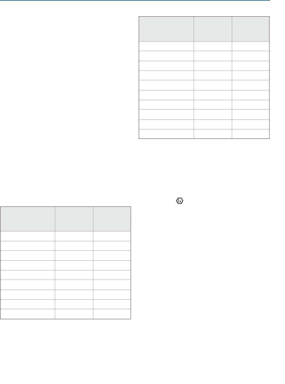
Product Certifications
November 2016
Reference Manual
00809-0100-4408, Rev AA
150 Product Certifications
PRELIMINARY
Specific Conditions of Use (X):
1. The Model 5408 Level Transmitter will not pass the
500Vrms dielectric strength test between the circuits
and the earth ground. This must be taken into
account during installation.
2. Non-standard paint options (paint options other than
Rosemount Blue) may cause risk from Electrostatic
discharge. Avoid installation that could cause
electrostatic build-up on painted surfaces, and only
clean the painted surfaces with a damp cloth.
3. Appropriate cable, glands, and plugs need to be
suitable for a temperature of 5°C greater than the
maximum specified ambient temperature for location
where installed.
4. The Transmitter can be installed in the boundary wall
between a Zone 0 and Zone 1 area. In this
configuration, the process connection is installed in
Zone 0, while the transmitter housing is installed in
Zone 1. Refer to Control Drawing D7000002-885.
5. Using the box provided on the nameplate, the User
shall permanently mark the type of protection chosen
for the specific installation. Once the type of
protection has been marked it shall not be changed.
6. *) LCD Display option (M5) is limited to minimum -34
°C Ambient and Process Temperature.
7. The applicable temperature class, ambient
temperature range and process temperature range of
the equipment is as follows;
B.9 Europe
E1 ATEX Flameproof
Certificate: FM15ATEX0055X
Standards: EN 60079-0:2012, EN 60079-1:2014, EN
60079-26:2015, EN 60079-31:2014, EN
60529+A1+A2:2013
Markings: II 1/2G Ex db IIC T6…T2 Ga/Gb
II 2D Ex tb IIIC T85°C… T250°C Db, IP65
*) (-55°CTa+70 °C)
Specific Conditions of Use (X):
1. Flamepath joints are not for repair. Contact the
manufacturer.
2. Non-standard paint options (paint options other than
Rosemount Blue) may cause risk from Electrostatic
discharge. Avoid installation that could cause
electrostatic build-up on painted surfaces, and only
clean the painted surfaces with a damp cloth.
3. Appropriate cable, glands, and plugs need to be
suitable for a temperature of 5°C greater than the
maximum specified ambient temperature for location
where installed.
4. The Transmitter can be installed in the boundary wall
between a Category 1 and Category 2 location. In this
configuration, the process connection is installed in
Category 1, while the transmitter housing is installed
in Category 2. Refer to Control Drawing
D7000002-885.
5. For Equipment Marked Ex tb IIIC T85°C…T250°C Db:
- Cable entries must be used which maintain the
ingress protection of the enclosure to at least IP65.
For Divisions:
Temperature Class /
Maximum Surface
Temperature
Ambient
Temperature
Range
Process
Temperature
Range
Division Gas Groups:
T2 -55°CTa70°C -55°C to 250°C
T3 -55°CTa70°C -55°C to 195°C
T4 -55°CTa70°C -55°C to 130°C
Division Dust Groups:
T165°C -55°CTa70°C -55°C to 160°C
T135°C -55°CTa70°C -55°C to 130°C
T100°C -55°CTa70°C -55°C to 95°C
T85°C -55°CTa70°C -55°C to 80°C
For Zones:
Temperature Class /
Maximum Surface
Temperature
Ambient
Temperature
Range
Process
Temperature
Range
Zone Gas Groups:
T2 -55°CTa70°C -55°C to 250°C
T3 -55°CTa70°C -55°C to 195°C
T4 -55°CTa70°C -55°C to 130°C
Zone Dust Groups:
T250°C -55°CTa70°C -55°C to 250°C
T200°C -55°CTa70°C -55°C to 195°C
T135°C -55°CTa70°C -55°C to 130°C
T100°C -55°CTa70°C -55°C to 95°C
T85°C -55°CTa70°C -55°C to 80°C
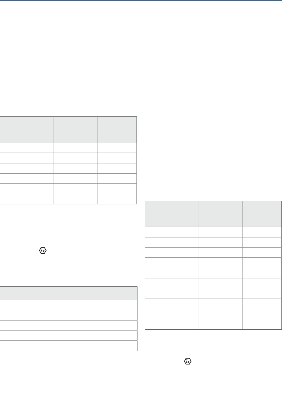
151
Product Certifications
Product Certifications
November 2016
Reference Manual
00809-0100-4408, Rev AA
PRELIMINARY
- To maintain the ingress protection ratings (IP65),
Covers and Sensor Module to be fully tightened and
PTFE tape or pipe dope is required for cable entries
and blanking plugs. See Instruction Manual on
application requirements.
6. Install per Control Drawing D7000002-885.
7. Using the box provided on the nameplate, the User
shall permanently mark the type of protection chosen
for the specific installation. Once the type of
protection has been marked it shall not be changed.
8. *) LCD Display option (M5) is limited to minimum -34
°C Ambient and Process Temperature.
9. The applicable temperature class, ambient
temperature range and process temperature range of
the equipment is as follows;
I1 ATEX Intrinsic Safety
Certificate: FM15ATEX0055X
Standards: EN 60079-0:2012, EN 60079-11:2012,
EN 60079-26:2015
Markings: II 1G Ex ia IIC T4…T2 Ga
II 1/2G Ex ib IIC T4…T2 Ga/Gb
II 1D Ex ia IIIC T135°C…T250°C Da
II 2D Ex ib IIIC T135°C…T250°C Db
(-55°CTa+70°C)
Specific Conditions of Use (X):
1. The Model 5408 Level Transmitter will not pass the
500Vrms dielectric strength test between the circuits
and the earth ground. This must be taken into
account during installation.
2. Non-standard paint options (paint options other than
Rosemount Blue) may cause risk from Electrostatic
discharge. Avoid installation that could cause
electrostatic build-up on painted surfaces, and only
clean the painted surfaces with a damp cloth.
3. Appropriate cable, glands, and plugs need to be
suitable for a temperature of 5°C greater than the
maximum specified ambient temperature for location
where installed.
4. The Transmitter can be installed in the boundary wall
between a Category 1 and Category 2 location. In this
configuration, the process connection is installed in
Category 1, while the transmitter housing is installed
in Category 2. Refer to Control Drawing
D7000002-885.
5. Using the box provided on the nameplate, the User
shall permanently mark the type of protection chosen
for the specific installation. Once the type of
protection has been marked it shall not be changed.
6. The applicable temperature class, ambient
temperature range and process temperature range of
the equipment is as follows;
N1 ATEX Type N: Non-Sparking
Certificate: FM15ATEX0056X
Standards: EN 60079-0:2012, EN 60079-15:2010
Markings: II 3G Ex nA IIC T4…T2 Gc, IP65
*) (-55°CTa+70°C)
V42.4V, I23 mA
Temperature Class /
Maximum Surface
Temperature
Ambient
Temperature
Range
Process
Temperature
Range
Gas & Dust Groups:
T2 / T250°C -55°CTa70°C -55°C to 250°C
T3 / T200°C -55°CTa70°C -55°C to 195°C
T4 / T135°C -55°CTa70°C -55°C to 130°C
T5 / T100°C -55°CTa70°C -55°C to 95°C
T6 / T85°C -55°CTa70°C -55°C to 80°C
Safety Parameter HART
Voltage Ui30 V
Current Ii133 mA
Power Pi1.0 W
Capacitance Ci7.3 nF
Inductance Li0
Temperature Class /
Maximum Surface
Temperature
Ambient
Temperature
Range
Process
Temperature
Range
Gas Groups:
T2 -55°CTa70°C -55°C to 250°C
T3 -55°CTa70°C -55°C to 195°C
T4 -55°CTa70°C -55°C to 130°C
Dust Groups:
T250°C -55°CTa70°C -55°C to 250°C
T200°C -55°CTa70°C -55°C to 195°C
T135°C -55°CTa70°C -55°C to 130°C
T100°C -55°CTa70°C -55°C to 95°C
T85°C -55°CTa70°C -55°C to 80°C

Product Certifications
November 2016
Reference Manual
00809-0100-4408, Rev AA
152 Product Certifications
PRELIMINARY
Specific Conditions of Use (X):
1. The Model 5408 Level Transmitter will not pass the
500Vrms dielectric strength test between the circuits
and the earth ground. This must be taken into
account during installation.
2. Non-standard paint options (paint options other than
Rosemount Blue) may cause risk from Electrostatic
discharge. Avoid installation that could cause
electrostatic build-up on painted surfaces, and only
clean the painted surfaces with a damp cloth.
3. Appropriate cable, glands, and plugs need to be
suitable for a temperature of 5°C greater than the
maximum specified ambient temperature for location
where installed.
4. *) LCD Display option (M5) is limited to minimum -34
°C Ambient and Process Temperature.
5. The applicable temperature class, ambient
temperature range and process temperature range of
the equipment is as follows;
B.10 International
E7 IECEx Flameproof
Certificate: IECEx FMG15.0033X
Standards: IEC 60079-0:2011, IEC 60079-1:2014-06,
IEC 60079-11:2011; IEC 60079-26:2014,
IEC 60079-31:2013
Markings: Ex db IIC T6…T2 Ga/Gb
Ex tb IIIC T85 °C…T250°C Db IP65
*) (-55°CTa+70 °C)
Specific Conditions of Use (X):
1. Flamepath joints are not for repair. Contact the
manufacturer.
2. Non-standard paint options (paint options other than
Rosemount Blue) may cause risk from Electrostatic
discharge. Avoid installation that could cause
electrostatic build-up on painted surfaces, and only
clean the painted surfaces with a damp cloth.
3. Appropriate cable, glands, and plugs need to be
suitable for a temperature of 5°C greater than the
maximum specified ambient temperature for location
where installed.
4. The Transmitter can be installed in the boundary wall
between EPL Ga and EPL Gb. In this configuration, the
process connection is EPL Ga, while the transmitter
housing is EPL Gb. Refer to Control Drawing
D7000002-885.
5. For Equipment Marked Ex tb IIIC T85°C…T250°C Db:
- Cable entries must be used which maintain the
ingress protection of the enclosure to at least IP65.
- To maintain the ingress protection ratings (IP65),
Covers and Sensor Module to be fully tightened and
PTFE tape or pipe dope is required for cable entries
and blanking plugs. See Instruction Manual on
application requirements.
6. Install per Control Drawing D7000002-885.
7. Using the box provided on the nameplate, the User
shall permanently mark the type of protection chosen
for the specific installation. Once the type of
protection has been marked it shall not be changed.
8. *) LCD Display option (M5) is limited to minimum -34
°C Ambient and Process Temperature.
9. The applicable temperature class, ambient
temperature range and process temperature range of
the equipment is as follows;
I7 IECEx Intrinsic Safety
Certificate: IECEx FMG15.0033X
Standards: IEC 60079-0:2011, IEC 60079-11:2011,
IEC 60079-26:2014
Markings: Ex ia IIC T4…T2 Ga
Ex ib IIC T4…T2 Ga/Gb
Ex ia IIIC T135°C…T250°C Da
Ex ib IIIC T135°C…T250°C Da/Db
(-55°CTa+70°C)
Temperature Class Ambient
Temperature
Range
Process
Temperature
Range
T2 -55°CTa70°C -55°C to 250°C
T3 -55°CTa70°C -55°C to 195°C
T4 -55°CTa70°C -55°C to 130°C
Temperature Class /
Maximum Surface
Temperature
Ambient
Temperature
Range
Process
Temperature
Range
Gas & Dust Groups
T2 / T250°C -55°CTa70°C -55°C to 250°C
T3 / T200°C -55°CTa70°C -55°C to 195°C
T4 / T135°C -55°CTa70°C -55°C to 130°C
T5 / T100°C -55°CTa70°C -55°C to 95°C
T6 / T85°C -55°CTa70°C -55°C to 80°C

153
Product Certifications
Product Certifications
November 2016
Reference Manual
00809-0100-4408, Rev AA
PRELIMINARY
Specific Conditions of Use (X):
1. The Model 5408 Level Transmitter will not pass the
500Vrms dielectric strength test between the circuits
and the earth ground. This must be taken into
account during installation.
2. Non-standard paint options (paint options other than
Rosemount Blue) may cause risk from Electrostatic
discharge. Avoid installation that could cause
electrostatic build-up on painted surfaces, and only
clean the painted surfaces with a damp cloth.
3. Appropriate cable, glands, and plugs need to be
suitable for a temperature of 5°C greater than the
maximum specified ambient temperature for location
where installed.
4. The Transmitter can be installed in the boundary wall
between EPL Ga and EPL Gb. In this configuration, the
process connection is EPL Ga, while the transmitter
housing is EPL Gb. Refer to Control Drawing
D7000002-885.
5. Using the box provided on the nameplate, the User
shall permanently mark the type of protection chosen
for the specific installation. Once the type of
protection has been marked it shall not be changed.
6. The applicable temperature class, ambient
temperature range and process temperature range of
the equipment is as follows;
N7 IECEx Type N: Non-Sparking
Certificate: IECEx FMG15.0033X
Standards: IEC 60079-0:2011, IEC 60079-15:2010
Markings: Ex nA IIC T4…T2 Gc
*) (-55°CTa+70°C), IP65
V42.4V, I23 mA
Specific Conditions of Use (X):
1. The Model 5408 Level Transmitter will not pass the
500Vrms dielectric strength test between the circuits
and the earth ground. This must be taken into
account during installation.
2. Non-standard paint options (paint options other than
Rosemount Blue) may cause risk from Electrostatic
discharge. Avoid installation that could cause
electrostatic build-up on painted surfaces, and only
clean the painted surfaces with a damp cloth.
3. Appropriate cable, glands, and plugs need to be
suitable for a temperature of 5°C greater than the
maximum specified ambient temperature for location
where installed.
4. *) LCD Display option (M5) is limited to minimum -34
°C Ambient and Process Temperature.
5. The applicable temperature class, ambient
temperature range and process temperature range of
the equipment is as follows;
B.11 Approval drawings
The installation guidelines presented by the System Control
Drawing must be followed in order to maintain certified
ratings for installed transmitters.
Safety Parameter HART
Voltage Ui30 V
Current Ii133 mA
Power Pi1.0 W
Capacitance Ci7.3 nF
Inductance Li0
Temperature Class /
Maximum Surface
Temperature
Ambient
Temperature
Range
Process
Temperature
Range
Gas Groups:
T2 -55°CTa70°C -55°C to 250°C
T3 -55°CTa70°C -55°C to 195°C
T4 -55°CTa70°C -55°C to 130°C
Dust Groups:
T250°C -55°CTa70°C -55°C to 250°C
T200°C -55°CTa70°C -55°C to 195°C
T135°C -55°CTa70°C -55°C to 130°C
T100°C -55°CTa70°C -55°C to 95°C
T85°C -55°CTa70°C -55°C to 80°C
Temperature Class /
Maximum Surface
Temperature
Ambient
Temperature
Range
Process
Temperature
Range
T2 -55°CTa70°C -55°C to 250°C
T3 -55°CTa70°C -55°C to 195°C
T4 -55°CTa70°C -55°C to 130°C
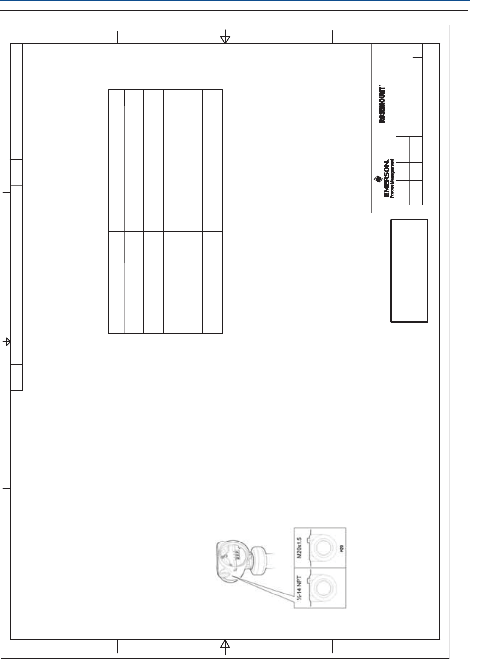
Product Certifications
November 2016
Reference Manual
00809-0100-4408, Rev AA
154 Product Certifications
PRELIMINARY
Figure B-1. D7000002-885 - System Control Drawing
System Control Drawing
Rosemount 5408 Series
D7000002-885
6
5408
1524ESa-LN
EAp A3
15
1
1525
D7000002-885
FM APPROVED PRODUCT
No revisions to this drawing
without prior Factory Mutual
Approval.
(General Information)
WARNING –Substitution of components may impair Intrinsic Safety.
WARNING –To prevent ignition of flammable or combustible atmospheres, disconnect power
before servicing.
AVERTISSEMENT –La substitution de composants peut compromettre la sécurité intrinsèque
AVERTISSEMENT – Ne pas ouvrir en cas de presence d’atmosphere explosive
1. No revision to drawing without prior FM Approval.
2. Associated apparatus manufacturer’s installation drawing must be followed when
installing this equipment.
3. Installations in the U.S. should be in accordance with ANSI/ISA RP12.06.01
“Installation of Intrinsically Safe Systems for Hazardous (Classified) Locations” and
the latest edition of the National Electrical Code (ANSI/NFPA 70).
4. Installation in Canada should be in accordance with the latest edition of the C22.1
Canadian Electrical Code, Part I.
5. Installations in Europe shall comply with the relevant requirements of EN 60079-14
and applicable National regulations.
6. Installations for IECEx certification shall be in accordance with latest editions of the
wiring practices for the country of origin.
7. The EPL Ga partition wall is made of stainless steel and a welded fused glass/
stainless steel lens.
8. The EPL Ga/Gb separation is invalidated if the transmitter is removed from the
antenna connection i.e. there is a risk of flammable gas release and flame entrance.
Disconnect power before removing the transmitter.
9. Thread size either ½-14 NPT or M20x1.5. Identification of thread size and type (No
marking = ½-14 NPT).
ISSUED BY
1234
FORM REV AA
A
D
A
D
BB
C
C
WEEK
APPROVED BY
WEEK
ISSUESIZE
DOC. TYPE
PRODUCT CODE
SHEET
THE COPYRIGHT/OWNERSHIP OF
OF
MUST NOT BE USED WITHOUT AUTHORIZATION OR BROUGHT
THIS DOCUMENT IS AND WILL REMAIN OURS. THE DOCUMENT
PARTY. CONTRAVENTION WILL BE PROSECUTED. ROSEMOUNT TANK RADAR AB, SWEDEN
TO THE KNOWLEDGE OF A THIRD
DRAWING NO.
TITLE
Rosemount Tank Radar AB, Layoutvägen 1, S-435 33 MÖLNLYCKE, SWEDEN
SYSTEM CONTROL DRAWING –ROSEMOUNT 5408 SERIES
GENERAL INFORMATION
CHANGE ORDER NO. WEEKISSUECHANGE ORDER NO. WEEKISSUECHANGE ORDER NO. WEEKISSUE
1SME-8739 1616
CONDUIT THREAD, BOTH SIDES
(see note 9)
10. Additional installation requirements are found in the Quick Start Guide (doc no 00825-0100-4408) and the
Product Certification Document (doc no 00825-0200 4408).
-15 … 363 psig (-1 ... 25 bar)
-40… 392 °F (-40 … 200 °C)
Antenna Type Operating Temperature and Pressure
Cone Antenna (PTFE seal)
Cone Antenna (PEEK seal, FVMQ)
Cone Antenna (PEEK seal, Kalrez)
Parabolic Antenna, Swivel Mount
Parabolic Antenna, Fixed Mount
-15 … 754 psig (-1 ... 52 bar)
-76… 338 °F (-60 … 170 °C)
-15 … 754 psig (-1 ... 52 bar)
-13… 482 °F (-25 … 250 °C)
-15 … 43 psig (-1 ... 3 bar)
-40… 392 °F (-40 … 200 °C)
-15 … 43 psig (-1 ... 3 bar)
-40… 392 °F (-40 … 200 °C)
11. See table below for applicable P/T rating for different antenna types.
12. The bottom of the Transmitter head is approved as a SINGLE SEAL device, acc to ANSI/ISA 12.27.01, up to a
process pressure of 160 bar. (Materials acc to Note 7).
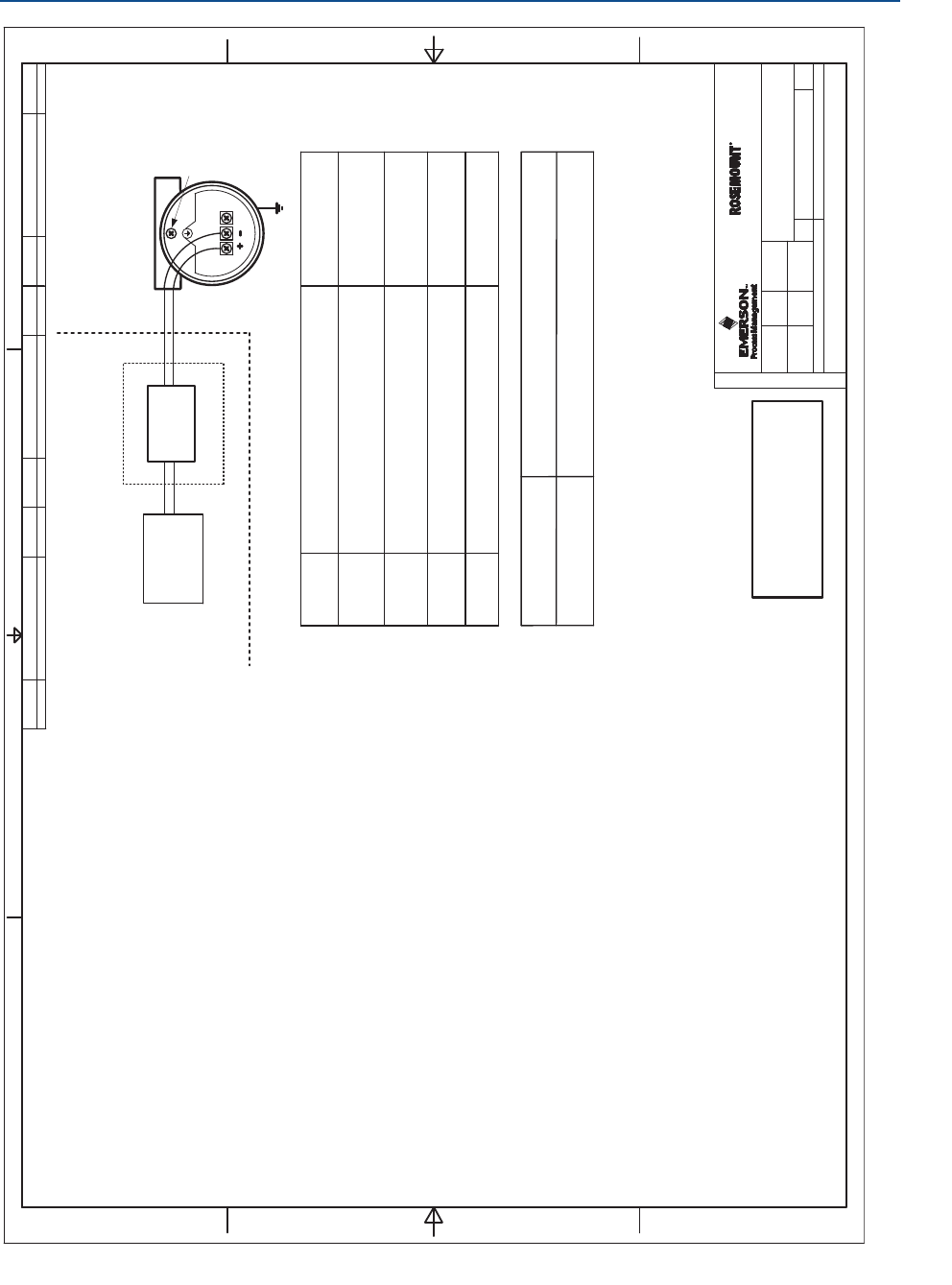
155
Product Certifications
Product Certifications
November 2016
Reference Manual
00809-0100-4408, Rev AA
PRELIMINARY
System Control Drawing
Rosemount 5408 Series
D7000002-885
6
5408
1524ESa-LN
EAp A3
25
1
1525
Ground Terminal,
External
Ground Terminal,
Internal
HAZARDOUS LOCATION /
EXPLOSIVE ATMOSPHERE
(ZONE 0/20, DIVISION 1)
(ZONE 1/21, DIVISION 1)
UNCLASSIFIED LOCATION
The Entity concept allows interconnection of intrinsically safe apparatus to associated
apparatus not specifically examined in combination as a system. The approved values of max.
open circuit voltage (Uo, Voc or Vt) and max. short circuit current (Io, Isc or It) and max. power
(Po or Voc x Isc / 4 or Vt x It / 4), for the associated apparatus must be less than or equal to the
maximum safe input voltage (Ui), maximum safe input current (Ii), and maximum safe input
power (Pi) of the intrinsically safe apparatus. In addition, the approved max. allowable
connected capacitance (Ca or Co) of the associated apparatus must be greater than the sum of
the interconnecting cable capacitance and the unprotected internal capacitance (Ci) of the
intrinsically safe apparatus, and the approved max. Allowable connected inductance (La or Lo)
of the associated apparatus must be greater than the sum of the interconnecting cable
inductance and the unprotected internal inductance (Li) of the intrinsically safe apparatus.
ENTITY CONCEPT APPROVALS
Intrinsically safe, EPL Ga Installation
[ia]
BARRIER
ASSOCIATED APPARATUS
POWER
SUPPLY
D7000002-885
FM APPROVED PRODUCT
No revisions to this drawing
without prior Factory Mutual
Approval.
(Intrinsically safe, EPL Ga installation)
Ui ≤30V, Ii ≤133 mA
Pi ≤1W,Ci=7.3nF,Li=0uH
WARNING –Substitution of components may impair Intrinsic Safety.
WARNING –To prevent ignition of flammable or combustible atmospheres, disconnect power
before servicing.
AVERTISSEMENT –La substitution de composants peut compromettre la sécurité intrinsèque
AVERTISSEMENT – Ne pas ouvrir en cas de presence d’atmosphere explosive
Notes
1. No revision to drawing without prior FM Approval.
2. The Associated Apparatus must be FM Approved for installations in the U.S.
3. The Associated Apparatus must be Canadian Approved for Installations in Canada.
4. The Associated Apparatus must be ATEX Certified for Installations in Europe.
5. The Associated Apparatus must be IECEx Certified for IECEx installations.
6. Associated apparatus manufacturer’s installation drawing must be followed when
installing this equipment.
7. Installations in the U.S. should be in accordance with ANSI/ISA RP12.06.01
“Installation of Intrinsically Safe Systems for Hazardous (Classified) Locations” and
the latest edition of the National Electrical Code (ANSI/NFPA 70).
8. Resistance between Intrinsically Safe Ground and earth ground must be less than
1.0 Ohm.
9. Installation in Canada should be in accordance with the latest edition of the C22.1
Canadian Electrical Code, Part I.
10. Installations in Europe shall comply with the relevant requirements of EN 60079-14
and applicable National regulations.
11. Installations for IECEx certification shall be in accordance with latest editions of the
wiring practices for the country of origin.
12. The Entity Concept allows interconnection of associated apparatus and intrinsically
safe apparatus with when the following is true:
Uo≤ Ui,I
o≤ Ii,P
o≤ Pi,C
o≤Ci+C
cable;L
o≤Li+L
cable.
Safe Apparatus for use in:
IS Class I, DIV 1, GP A-G T4…T2
CL I, Zone 0 AEx ia IIC T4…T2
Zone 20 AEx ia IIIC T85°C…T250°C
IS Class I, DIV 1, GP A-G T4…T2
Ex ia IIC T4…T2
Ex ia IIIC T85°C…T250°C
II 1G Ex ia IIC T4..T2 Ga
II 1D Ex ia IIIC T85°C...T250°C Da
Ex ia IIC T4..T2 Ga
Ex ia IIIC T85°C...T250°C Da
FM
US
FMc
ATEX
IECEx
Model Intrinsic Entity Parameters
Ambient
Temperature Limits
4-20mA / HART
-55°C≤Ta≤+70°C
-55°C≤Ta≤+70°C
-55°C≤Ta≤+70°C
-55°C≤Ta≤+70°C
ISSUED BY
1234
FORM REV AA
A
D
A
D
BB
C
C
WEEK
APPROVED BY
WEEK
ISSUESIZE
DOC. TYPE
PRODUCT CODE
SHEET
THE COPYRIGHT/OWNERSHIP OF
OF
MUST NOT BE USED WITHOUT AUTHORIZATION OR BROUGHT
THIS DOCUMENT IS AND WILL REMAIN OURS. THE DOCUMENT
PARTY. CONTRAVENTION WILL BE PROSECUTED. ROSEMOUNT TANK RADAR AB, SWEDEN
TO THE KNOWLEDGE OF A THIRD
DRAWING NO.
TITLE
Rosemount Tank Radar AB, Layoutvägen 1, S-435 33 MÖLNLYCKE, SWEDEN
CHANGE ORDER NO. WEEKISSUECHANGE ORDER NO. WEEKISSUECHANGE ORDER NO. WEEKISSUE
1SME-8739 1616
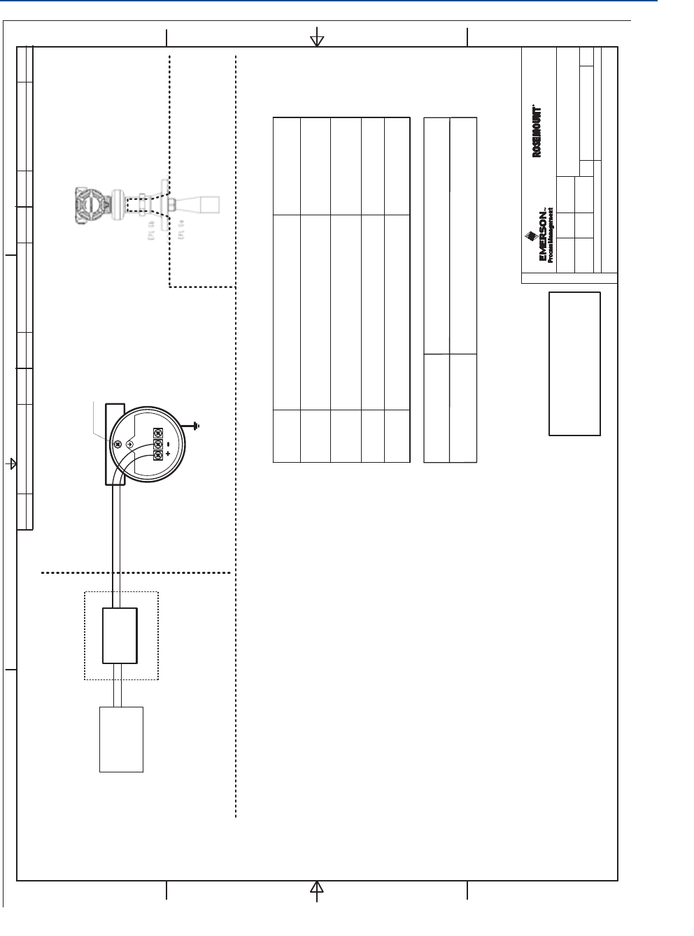
Product Certifications
November 2016
Reference Manual
00809-0100-4408, Rev AA
156 Product Certifications
PRELIMINARY
[ib]
BARRIER
CHANGE ORDER NO. WEEKISSUECHANGE ORDER NO. WEEKISSUECHANGE ORDER NO. WEEKISSUE
System Control Drawing
Rosemount 5408 Series
D7000002-885
6
5408
1524ESa-LN
EAp A3
35
1
1525
Ground Terminal,
External
Ground Terminal,
Internal
Intrinsically safe, EPL Gb installation
ASSOCIATED APPARATUS
POWER
SUPPLY
D7000002-885
FM APPROVED PRODUCT
No revisions to this drawing
without prior Factory Mutual
Approval.
(Intrinsically safe, EPL Gb installation)
Ui ≤30V, Ii ≤133 mA
Pi ≤1W, Ci = 7.3 nF, Li = 0 uH
WARNING –Substitution of components may impair Intrinsic Safety.
WARNING –To prevent ignition of flammable or combustible atmospheres, disconnect power
before servicing.
AVERTISSEMENT –La substitution de composants peut compromettre la sécurité intrinsèque
AVERTISSEMENT – Ne pas ouvrir en cas de presence d’atmosphere explosive
Notes
1. No revision to drawing without prior FM Approval.
2. The Associated Apparatus must be FM Approved for installations in the U.S.
3. The Associated Apparatus must be Canadian Approved for Installations in Canada.
4. The Associated Apparatus must be ATEX Certified for Installations in Europe.
5. The Associated Apparatus must be IECEx Certified for IECEx installations.
6. Associated apparatus manufacturer’s installation drawing must be followed when
installing this equipment.
7. Installations in the U.S. should be in accordance with ANSI/ISA RP12.06.01
“Installation of Intrinsically Safe Systems for Hazardous (Classified) Locations” and
the latest edition of the National Electrical Code (ANSI/NFPA 70).
8. Resistance between Intrinsically Safe Ground and earth ground must be less than
1.0 Ohm.
9. Installation in Canada should be in accordance with the latest edition of the C22.1
Canadian Electrical Code, Part I.
10. Installations in Europe shall comply with the relevant requirements of EN 60079-14
and applicable National regulations.
11. Installations for IECEx certification shall be in accordance with latest editions of the
wiring practices for the country of origin.
12. The Entity Concept allows interconnection of associated apparatus and intrinsically
safe apparatus with when the following is true:
Uo≤ Ui,I
o≤ Ii,P
o≤ Pi,C
o≤ Ci+C
cable;L
o≤Li+L
cable.
13. Listed intrinsic safety parameters apply only to associated apparatus with linear
output.
Model Intrinsic Entity Parameters
4-20mA / HART
HAZARDOUS LOCATION / EXPLOSIVE ATMOSPHERE
(ZONE 1/21)
UNCLASSIFIED LOCATION
Safe Apparatus for use in:
FM
US
FMc
ATEX
IECEx
Ambient
Temperature Limits
-55°C≤Ta≤+70°C
-55°C≤Ta≤+70°C
-55°C≤Ta≤+70°C
-55°C≤Ta≤+70°C
CL I, Zone 0/1 AEx ib IIC T4…T2
Zone 21 AEx ib IIIC T135°C…T250°C
II 1/2G Ex ib IIC T4…T2Ga/Gb
II 2D Ex ib IIIC T85°C… T250°C Db
Ex ib IIC T4…T2Ga/Gb
Ex ib IIIC T85°C… T250°C Db
HAZARDOUS AREA
(ZONE 0/21)
ISSUED BY
1234
FORM REV AA
A
D
A
D
BB
C
C
WEEK
APPROVED BY
WEEK
ISSUESIZE
DOC. TYPE
PRODUCT CODE
SHEET
THE COPYRIGHT/OWNERSHIP OF
OF
MUST NOT BE USED WITHOUT AUTHORIZATION OR BROUGHT
THIS DOCUMENT IS AND WILL REMAIN OURS. THE DOCUMENT
PARTY. CONTRAVENTION WILL BE PROSECUTED. ROSEMOUNT TANK RADAR AB, SWEDEN
TO THE KNOWLEDGE OF A THIRD
DRAWING NO.
TITLE
Rosemount Tank Radar AB, Layoutvägen 1, S-435 33 MÖLNLYCKE, SWEDEN
Ex ib IIC T4…T2
Ex ib IIIC T135°C…T250°C
1SME-8739 1616
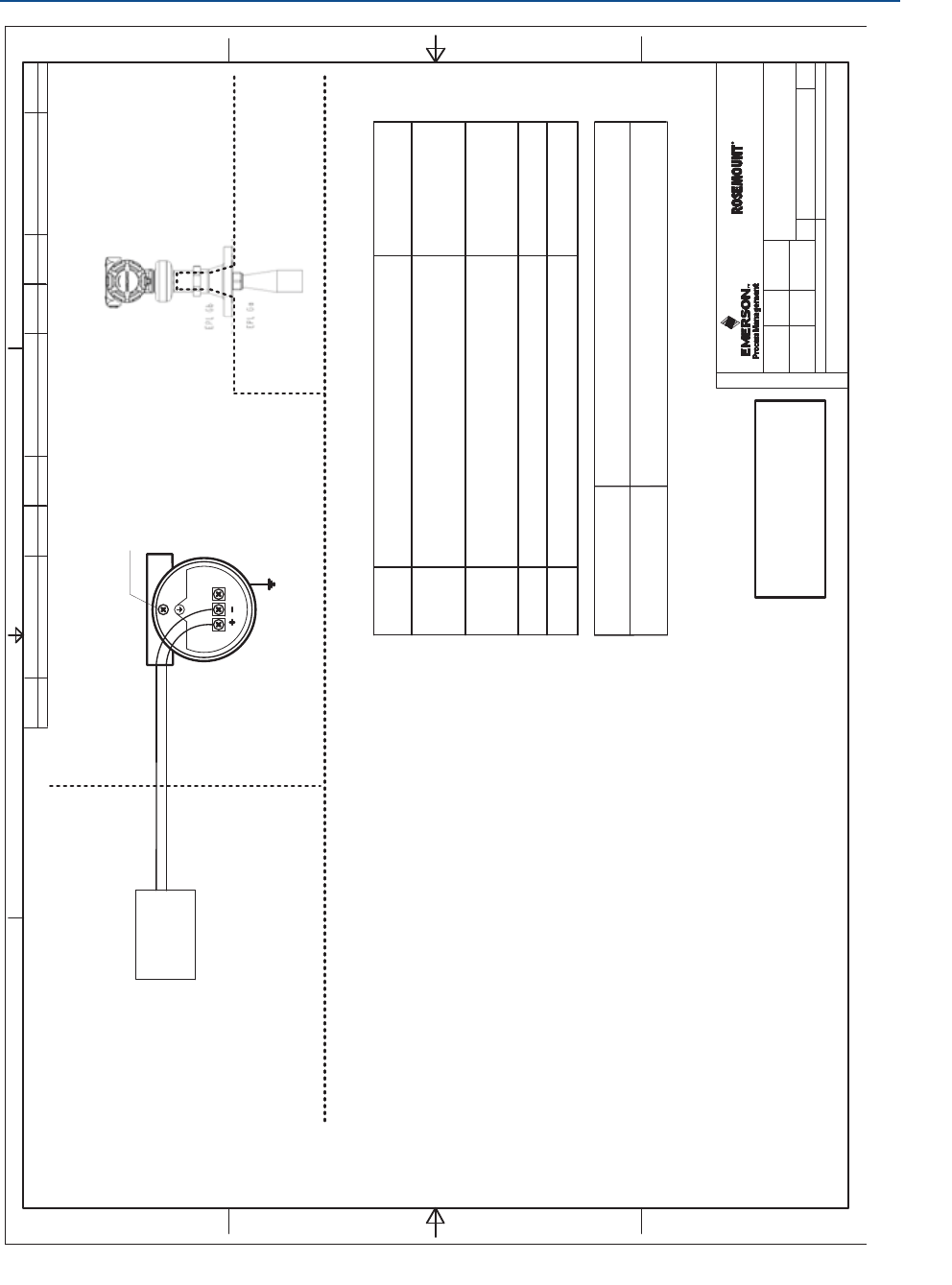
157
Product Certifications
Product Certifications
November 2016
Reference Manual
00809-0100-4408, Rev AA
PRELIMINARY
System Control Drawing
Rosemount 5408 Series
D7000002-885
6
5408
1524ESa-LN
EAp A3
45
1
1525
Ground Terminal,
External
Ground Terminal,
Internal
Flameproof/XP installation
POWER
SUPPLY
D7000002-885
FM APPROVED PRODUCT
No revisions to this drawing
without prior Factory Mutual
Approval.
(Flameproof/XP installation)
Ud42.4V, I d23 mA
WARNING –Substitution of components may impair Intrinsic Safety.
WARNING –To prevent ignition of flammable or combustible atmospheres, disconnect power
before servicing.
AVERTISSEMENT –La substitution de composants peut compromettre la sécurité intrinsèque
AVERTISSEMENT – Ne pas ouvrir en cas de presence d’atmosphere explosive
Notes
1. No revision to drawing without prior FM Approval.
2. The control room equipment connected to Associated Apparatus must not generate
more than 250 Vrms or Vdc.
3. Installations in the U.S. should be in accordance with the latest edition of the
National Electrical Code (ANSI/NFPA 70).
4. Installation in Canada should be in accordance with the latest edition of the C22.1
Canadian Electrical Code, Part I.
5. Installations in Europe shall comply with the relevant requirements of EN 60079-14
and applicable National regulations.
6. Installations for IECEx certification shall be in accordance with latest editions of the
wiring practices for the country of origin.
7. -50°C for Division, -55°C for Zone installation.
Safe Apparatus for use in:
FM
US
FMc
Model Normal Operating Parameters
Ambient
Temperature Limits
4-20mA / HART
-50°C≤Ta≤+70°C
(See note 7)
-50°C≤Ta≤+70°C
(See note 7)
HAZARDOUS LOCATION / EXPLOSIVE ATMOSPHERE
(ZONE 1/21 DIVISION 1)
UNCLASSIFIED LOCATION
HAZARDOUS AREA
(ZONE 0 DIVISION 1)
(ZONE 21 DIVISION 1)
XP Class I, DIV 1, GP A-D T6…T2
DIP CL II, III DIV 1, GP E-G T6…T3
CL I Zone 0/1 AEx db IIC T6..T2 ;
Zone 21 AEx tb IIIC T85°C...T250°C
ISSUED BY
1234
FORM REV AA
A
D
A
D
BB
C
C
WEEK
APPROVED BY
WEEK
ISSUESIZE
DOC. TYPE
PRODUCT CODE
SHEET
THE COPYRIGHT/OWNERSHIP OF
OF
MUST NOT BE USED WITHOUT AUTHORIZATION OR BROUGHT
THIS DOCUMENT IS AND WILL REMAIN OURS. THE DOCUMENT
PARTY. CONTRAVENTION WILL BE PROSECUTED. ROSEMOUNT TANK RADAR AB, SWEDEN
TO THE KNOWLEDGE OF A THIRD
DRAWING NO.
TITLE
Rosemount Tank Radar AB, Layoutvägen 1, S-435 33 MÖLNLYCKE, SWEDEN
XP Class I, DIV 1, GP A-D T6…T2
DIP CL II, III DIV 1, GP E-G T6…T3
Ex db IIC T6..T2 ;
Ex tb IIIC T85°C...T250°C
CHANGE ORDER NO. WEEKISSUECHANGE ORDER NO. WEEKISSUECHANGE ORDER NO. WEEKISSUE
1SME-8739 1616
ATEX
II 1/2G Ex db IIC T6..T2 Ga/Gb
II 2D Ex tb IIIC T85°C...T250°C Db
IECEx
Ex db IIC T6..T2 Ga/Gb
Ex tb IIIC T85°C...T250°C Db
-55°C≤Ta≤+70°C
-55°C≤Ta≤+70°C
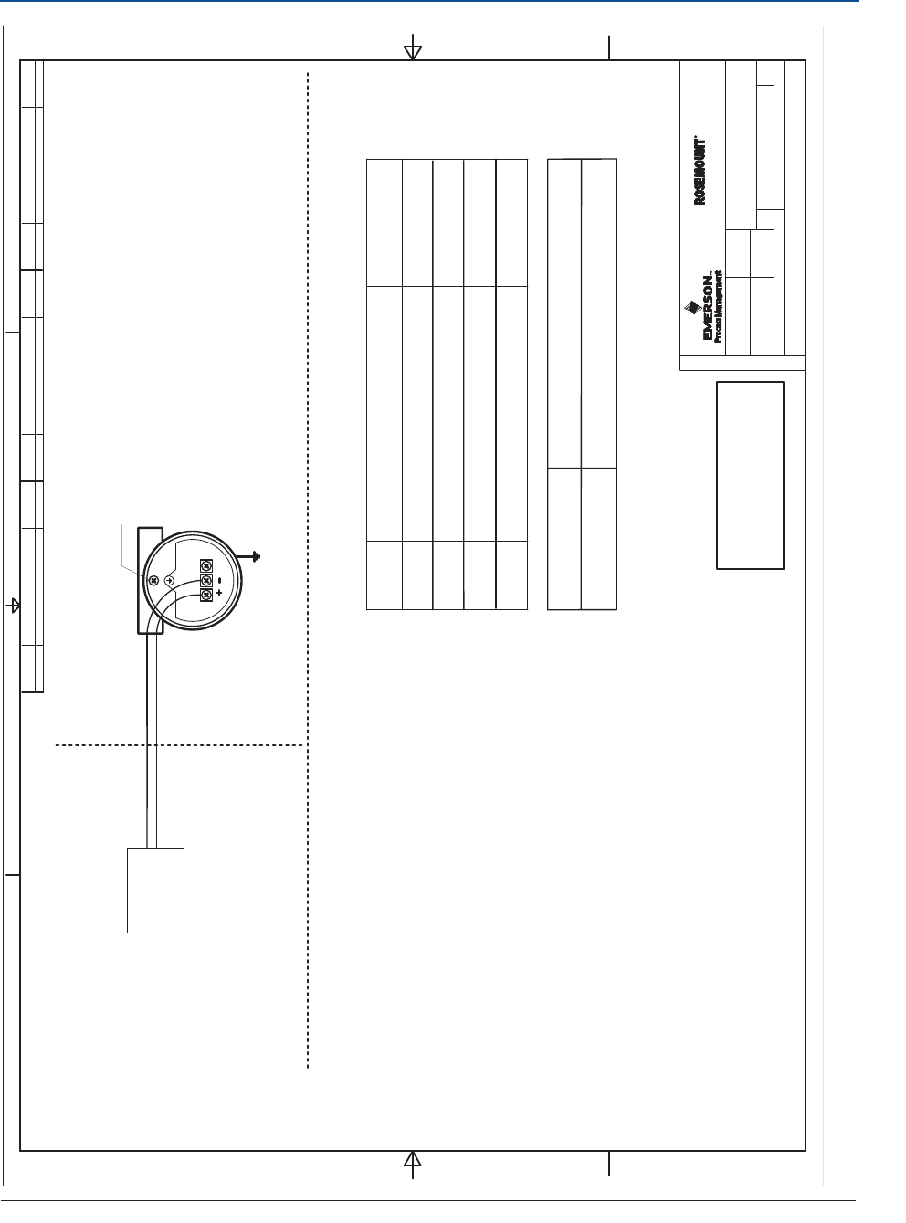
Product Certifications
November 2016
Reference Manual
00809-0100-4408, Rev AA
158 Product Certifications
PRELIMINARY
System Control Drawing
Rosemount 5408 Series
D7000002-885
6
5408
1524ESa-LN
EAp A3
55
1
1525
Ground Terminal,
External
Ground Terminal,
Internal
Non-incendive installation
POWER
SUPPLY
D7000002-885
FM APPROVED PRODUCT
No revisions to this drawing
without prior Factory Mutual
Approval.
(Non-incendive installation)
WARNING –Substitution of components may impair Intrinsic Safety.
WARNING –To prevent ignition of flammable or combustible atmospheres, disconnect power
before servicing.
AVERTISSEMENT –La substitution de composants peut compromettre la sécurité intrinsèque
AVERTISSEMENT – Ne pas ouvrir en cas de presence d’atmosphere explosive
Notes
1. No revision to drawing without prior FM Approval.
2. Installations in the U.S. should be in accordance with the latest edition of the
National Electrical Code (ANSI/NFPA 70).
3. Installation in Canada should be in accordance with the latest edition of the C22.1
Canadian Electrical Code, Part I.
4. Installations in Europe shall comply with the relevant requirements of EN 60079-14
and applicable National regulations.
5. Installations for IECEx certification shall be in accordance with latest editions of the
wiring practices for the country of origin.
Safe Apparatus for use in:
FM
US
FMc
ATEX
IECEx
Model Normal operating parameters
Ambient
Temperature Limits
4-20mA / HART
-55°C≤Ta≤+70°C
-55°C≤Ta≤+70°C
-55°C≤Ta≤+70°C
-55°C≤Ta≤+70°C
HAZARDOUS LOCATION / EXPLOSIVE ATMOSPHERE
(ZONE 2 DIVISION 2 )
UNCLASSIFIED LOCATION
Ud42.4V, I d23 mA
Ex Na IIC T4…T2Gc
II 3G Ex Na IIC T4…T2Gc
NI CL I,DIV 2, GP A-D T4…T2
SCLll,lllDIV2,GPE-G T4…T3
ISSUED BY
1234
FORM REV AA
A
D
A
D
BB
CC
WEEK
APPROVED BY
WEEK
ISSUESIZE
DOC. TYPE
PRODUCT CODE
SHEET
THE COPYRIGHT/OWNERSHIP OF
OF
MUST NOT BE USED WITHOUT AUTHORIZATION OR BROUGHT
THIS DOCUMENT IS AND WILL REMAIN OURS. THE DOCUMENT
PARTY. CONTRAVENTION WILL BE PROSECUTED. ROSEMOUNT TANK RADAR AB, SWEDEN
TO THE KNOWLEDGE OF A THIRD
DRAWING NO.
TITLE
Rosemount Tank Radar AB, Layoutvägen 1, S-435 33 MÖLNLYCKE, SWEDEN
NI CL I,DIV 2, GP A-D T4…T2
S CL ll, lll DIV 2, GP E-G T4…T3
CHANGE ORDER NO. WEEKISSUECHANGE ORDER NO. WEEKISSUECHANGE ORDER NO. WEEKISSUE
1SME-8739 1616

Configuration Parameters
November 2016
Reference Manual
00809-0100-4408, Rev AA
159
Configuration Parameters
PRELIMINARY
Appendix C Configuration Parameters
Menu tree . . . . . . . . . . . . . . . . . . . . . . . . . . . . . . . . . . . . . . . . . . . . . . . . . . . . . . . . . . . . . . . page 160
Device setup . . . . . . . . . . . . . . . . . . . . . . . . . . . . . . . . . . . . . . . . . . . . . . . . . . . . . . . . . . . . page 162
Level setup . . . . . . . . . . . . . . . . . . . . . . . . . . . . . . . . . . . . . . . . . . . . . . . . . . . . . . . . . . . . . . page 165
Alert setup . . . . . . . . . . . . . . . . . . . . . . . . . . . . . . . . . . . . . . . . . . . . . . . . . . . . . . . . . . . . . . page 178
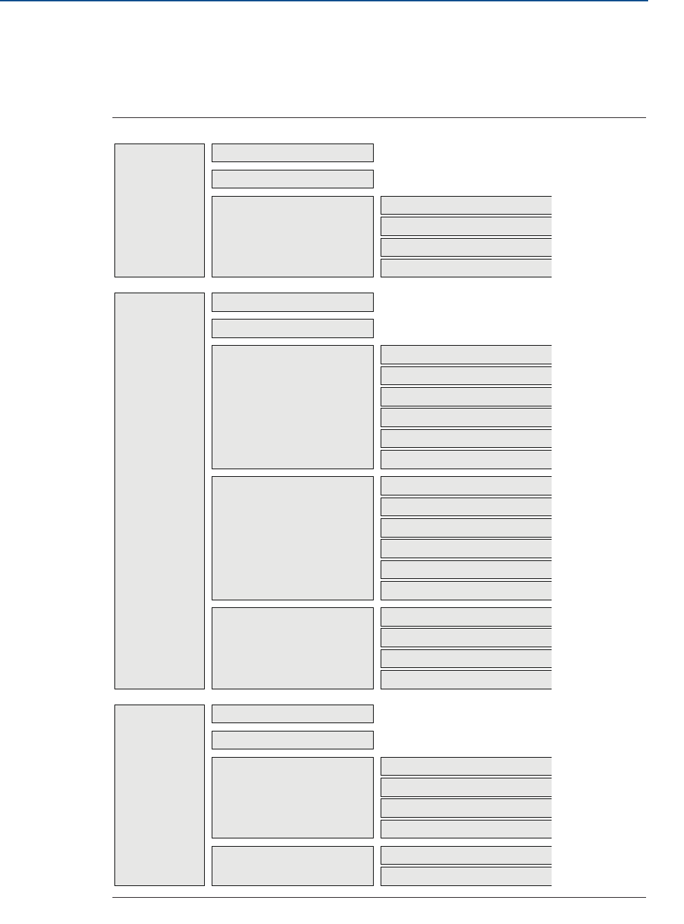
Configuration Parameters
November 2016
Reference Manual
00809-0100-4408, Rev AA
160 Configuration Parameters
PRELIMINARY
C.1 Menu tree
The menu tree structure in Figure C-1 is applicable for Rosemount Radar Master. For AMS
Device Manager and the Field Communicator, see Figure C-2.
Figure C-1. Menu Tree for Rosemount Radar Master
Overview
Configure
Primary Variables
Guided Setup
Verify Level
Device Setup
All Variables
Device Information Identification
Revisions
Alarm and Security
Upgrade
HART
Units
Simulate Measurement Values
Backup
Loop Test
Routine Maintenance
Upgrade
Analog Output
Display
Alarm Delay
Reset/Restore
Signal Quality Alert
High User Defined Alert
Low User Defined Alert
Security
Device Information
Level Setup
Alert Setup
Geometry
Environment
Volume
Scaled Variable
Antenna
Advanced
Service Tools Alerts
Echo Curve
Maintenance
Simulate
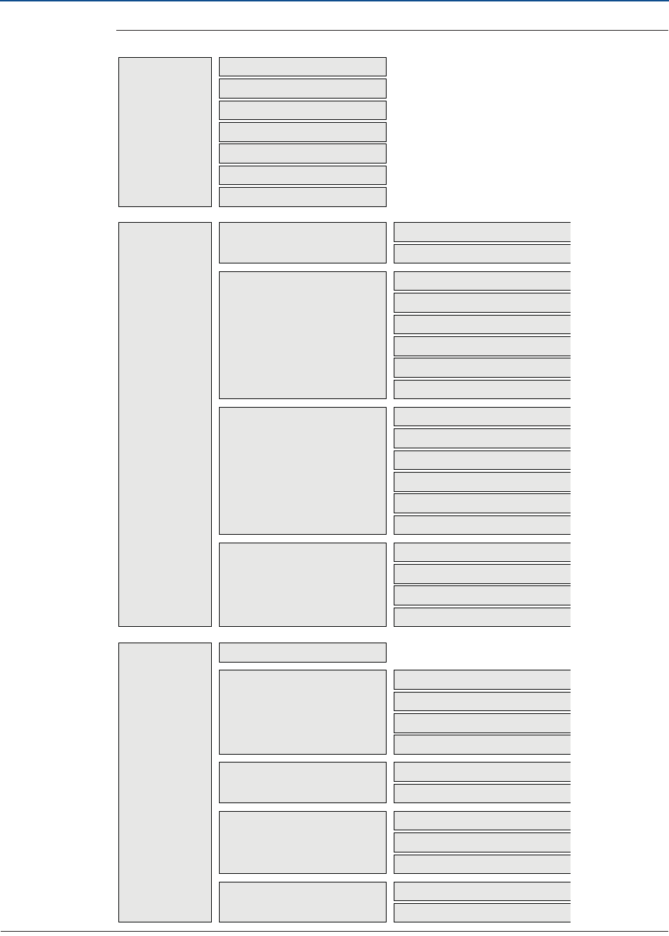
Configuration Parameters
November 2016
Reference Manual
00809-0100-4408, Rev AA
161
Configuration Parameters
PRELIMINARY
Figure C-2. Menu Tree for AMS Device Manager and Field Communicator
Overview
Configure
Device Status
Guided Setup
Manual Setup > Device Setup
Communication Status
PV
SV
TV
QV
Device Information
HART
Units
Basic Setup
Verify Level
Analog Output
Display
Alarm Delay
Process
Mapped Variables
Signal Quality
Device
Signal Quality Alert
High User Defined Alert
Low User Defined Alert
Security
Device Information
Manual Setup > Level Setup
Alert Setup
Geometry
Environment
Volume
Scaled Variable
Antenna
Advanced
Service Tools Alerts
Variables
Echo Peaks
Thresholds
Suppress
Echo Tuning
Reset/Restore
Routine MaintenanceMaintenance
Simulate Measurement Values
Analog Output > Loop test
Simulate

Configuration Parameters
November 2016
Reference Manual
00809-0100-4408, Rev AA
162 Configuration Parameters
PRELIMINARY
C.2 Device setup
C.2.1 HART
HART/polling address
The address range is 0 to 63. The transmitter operates in either standard mode with a 4–20
mA output signal or in multi-drop. When the transmitter is in multi-drop mode, the current
output is fixed to 4 mA.
Burst mode
When set to burst mode, the transmitter regularly sends out messages instead of waiting
for the host to request it.
Both the transmitter and host must be configured to operate in burst mode. Almost all
HART host systems today are designed to communicate in poll/response mode, not burst
mode. However, the Rosemount 333 HART Tri-Loop™ requires burst mode communication
(see section “Use with the HART Tri-Loop” on page 67).
Variable mapping
Up to four transmitter variables can be assigned for the HART protocol. The transmitter
outputs a 4-20 mA signal proportional to the primary variable. Additional variables are
available through the HART digital signal. See “Output variables” on page 123 for a list of
available transmitter variables.
Damping value
This parameter defines how fast the transmitter reacts to a change of the level value (step
response). The default value is 2 seconds.
A high value makes the level reading steady, while a low value allows the transmitter to
respond to rapid level changes (but the presented level value may be less steady).
Percent of range auxiliary
Set this parameter to output the percent of range for another transmitter variable (in
addition to the primary variable).
100% auxiliary
Value corresponding to 100% range of variable selected for percent of range auxiliary.
0% auxiliary
Value corresponding to 0% range of variable selected for percent of range auxiliary.
C.2.2 Units
The units for length, volume, temperature, and level rates are selectable. All configuration
parameters and transmitter variables will be expressed in these units. For information on
available units of measure, see “Output units” on page 123.
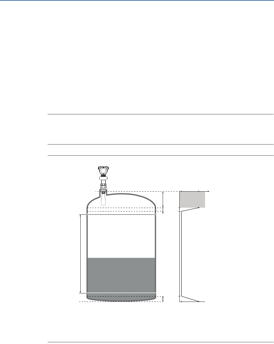
Configuration Parameters
November 2016
Reference Manual
00809-0100-4408, Rev AA
163
Configuration Parameters
PRELIMINARY
C.2.3 Analog output
The output source (primary variable), range values, and alarm mode are specified for the
analog output.
Primary variable
Select the desired transmitter variable to use for the analog output.
Upper/lower range value
Enter the range values that correspond to the analog output values 4 and 20 mA. The
transmitter will drive the output to saturation mode if a measured value goes outside the
4-20 mA range values.
Note
Measurements may not be possible in the Blind Zones, and measurements close to the Blind
Zones will have reduced accuracy. Therefore, the 4-20 mA points should be set outside
these zones (see Figure C-10).
Figure C-3. Example of Range Value Settings
A. Upper blind zone
B. Upper reduced accuracy zone
C. Lower reduced accuracy zone
D. Level measurement range 0-100%
Alarm mode
The transmitter automatically and continuously performs self-diagnostic routines. If a
failure or a measurement error is detected, the transmitter drives the output to selected
alarm limit (high or low).
0% (4 mA)
100% (20 mA)
A
B
D
C
Accuracy
± 0.08 in.
(2 mm) ± TBD in.
(TBD mm)

Configuration Parameters
November 2016
Reference Manual
00809-0100-4408, Rev AA
164 Configuration Parameters
PRELIMINARY
C.2.4 Display
Select variables to show on the optional LCD display (option code M5). If more than one
variable is selected, then the LCD display toggles between the output variables.
C.2.5 Security
Write protection
The transmitter can be write protected (with or without a password) to prevent
unauthorized changes.
Operational mode(1)
There are two Operational Modes to choose from for the Rosemount 5408:SIS:
Control/Monitoring and Safety (SIS).
If the transmitter is used as safety device in a Safety Instrumented System, the Operational
Mode must be set to Safety (SIS).
Safety mode(1)
When the operational mode is set to Safety (SIS), then the Safety Mode must be enabled for
the transmitter to become operational. When Safety Mode is enabled, the transmitter is
write protected (with or without a password) to prevent unauthorized changes.
Change counter(1)
A counter that increments each time the device enters active Safety Mode.
C.2.6 Device Information
Tag
Identifier of up to 8 characters for the transmitter used by host system. The tag is typically a
reference number, location, or duty description.
Long tag
Identifier of up to 32 characters for the transmitter used by host system. It is recommended
to enter both a short and a long tag (they may be the same).
Descriptor
The 16-character descriptor field can be used for any purpose.
Message
The 32-character message field can be used for any purpose, such as providing details of the
last configuration change.
Date
The date field can be used for any purpose, for example to save the date of the last
configuration change.
1. Applies only to Rosemount 5408:SIS (profile code F).
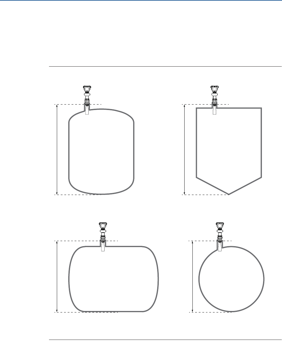
Configuration Parameters
November 2016
Reference Manual
00809-0100-4408, Rev AA
165
Configuration Parameters
PRELIMINARY
C.3 Level setup
C.3.1 Geometry
The transmitter configuration includes setting the tank geometry parameters, see
Figure C-4 and Figure C-5.
Figure C-4. Tank Geometry, Basic Dimensions
A. Device Reference Point
B. Reference Height
C. Zero Level
A
A
B
B
B
C
C
A
B
C
A
C
Cubical Tank
Horizontal cylinder
Vertical cylinder
Spherical tank
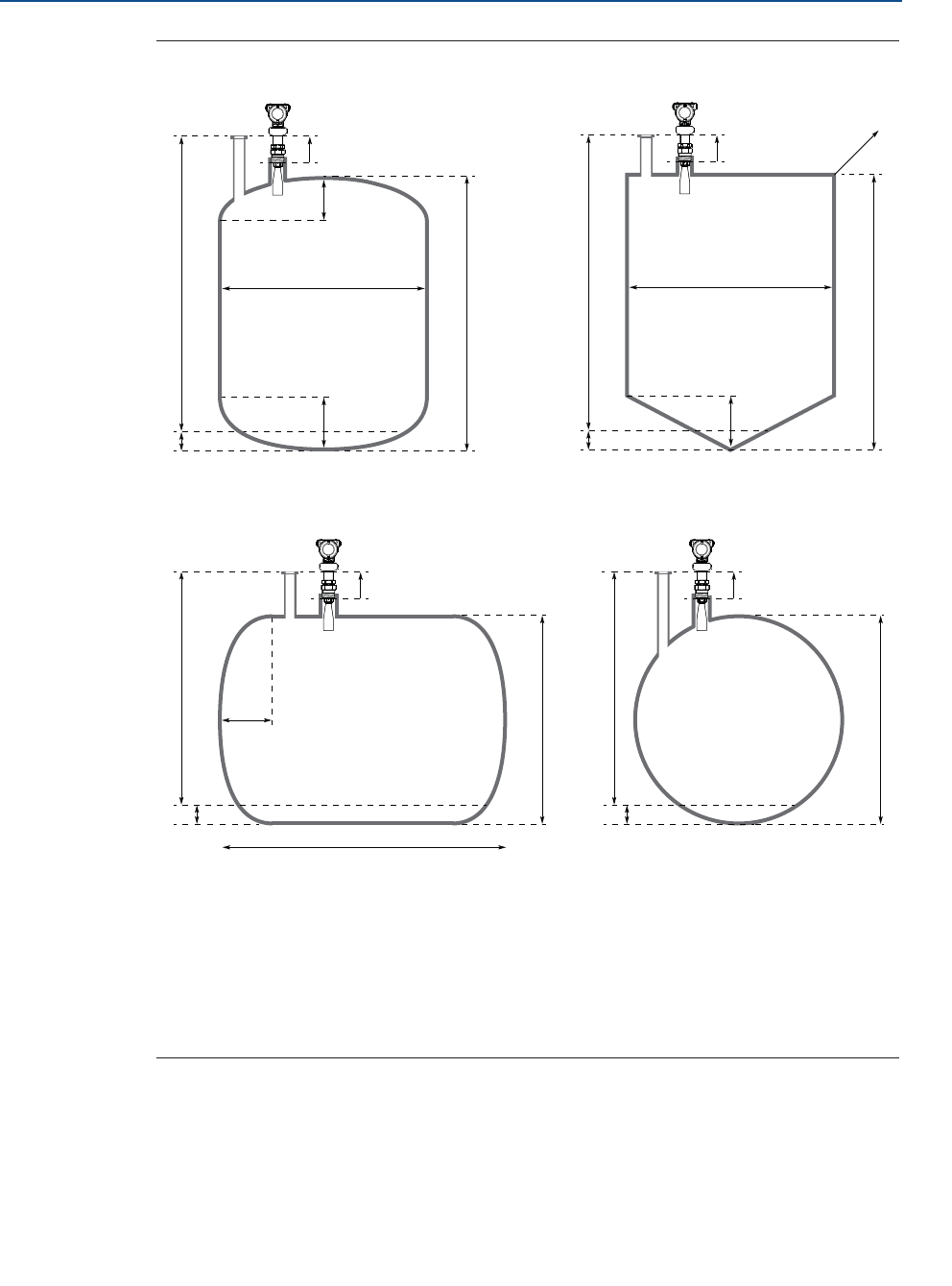
Configuration Parameters
November 2016
Reference Manual
00809-0100-4408, Rev AA
166 Configuration Parameters
PRELIMINARY
Figure C-5. Tank Geometry, All Dimensions
A.
B.
C.
D.
E.
F.
*
**
Tank Reference Point
Reference Height
Zero Level
Bottom Offset
Device Reference Point
Reference Offset
AMS Device Manager and Field Communicator
Rosemount Radar Master
G.
H.
I.
J.
K.
L.
Top Shape Height*/Top Height**
Width of Tank*/Width**
Bottom Shape Height*/Bottom Height**
Height of Tank*/Height**
End Shape Length*/End Length**
Length of Tank*/Length**
A
A
EF
G
H
H
I
B
BB
J
J
K
C
C
D
D
EF
+A
EF
H
I
B
J
L
CD
+
+A
EF
+
CD
J
Cubical Tank
Horizontal cylinder
Vertical cylinder
Spherical tank
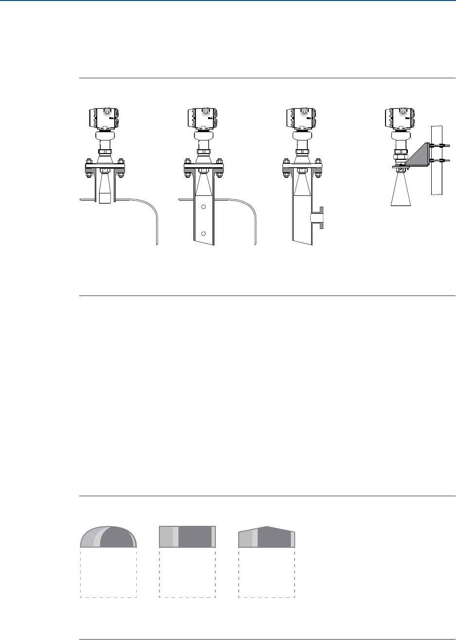
Configuration Parameters
November 2016
Reference Manual
00809-0100-4408, Rev AA
167
Configuration Parameters
PRELIMINARY
Mounting type
Select option best describing how transmitter is mounted on the tank. There are four
options to choose from: Nozzle, Still pipe, Chamber, and Bracket.
Figure C-6. Mounting Type
A. Nozzle
B. Still pipe
C. Chamber
D. Bracket (open air)
Inner diameter, pipe/chamber
Enter the inner diameter for the pipe or chamber in which the antenna is mounted. The
inner diameter value is used to compensate for the lower microwave propagation speed
inside the pipe/chamber. An incorrect value will give a scale factor error.
Tank shape
Select a tank shape that corresponds to the actual tank. If the actual tank does not match
one of the pre-defined tank shapes, then select Other (e.g. level measurements of sumps,
basins or ponds).
Tank top shape
Form of the upper tank closure.
Figure C-7. Tank Top Shape
A. Dome
B. Flat
C. Conical
ABCD
ABC

Configuration Parameters
November 2016
Reference Manual
00809-0100-4408, Rev AA
168 Configuration Parameters
PRELIMINARY
Tank bottom shape
Form of the lower tank closure.
Figure C-8. Tank Top Shape
A. Dome
B. Flat
C. Conical/pyramid
D. Flat, inclined (for vertical cylinder)
E. Flat, inclined (for cubical tank)
Tank end shape
For a horizontal tank, form of the tank ends. Same shape is assumed at both ends.
Figure C-9. Tank End Shape
A. Dome
B. Flat
Reference height
Distance between the Tank Reference Point (typically same as Device Reference Point) and
zero level.
Ensure the Reference Height is set as accurate as possible. The transmitter measures the
distance to the product surface and subtracts this value from the Reference Height to
determine the level.
Device reference point
Figure C-10 and Figure C-11 show the Device Reference Point for various antennas and tank
connections.
ABCD E
AB
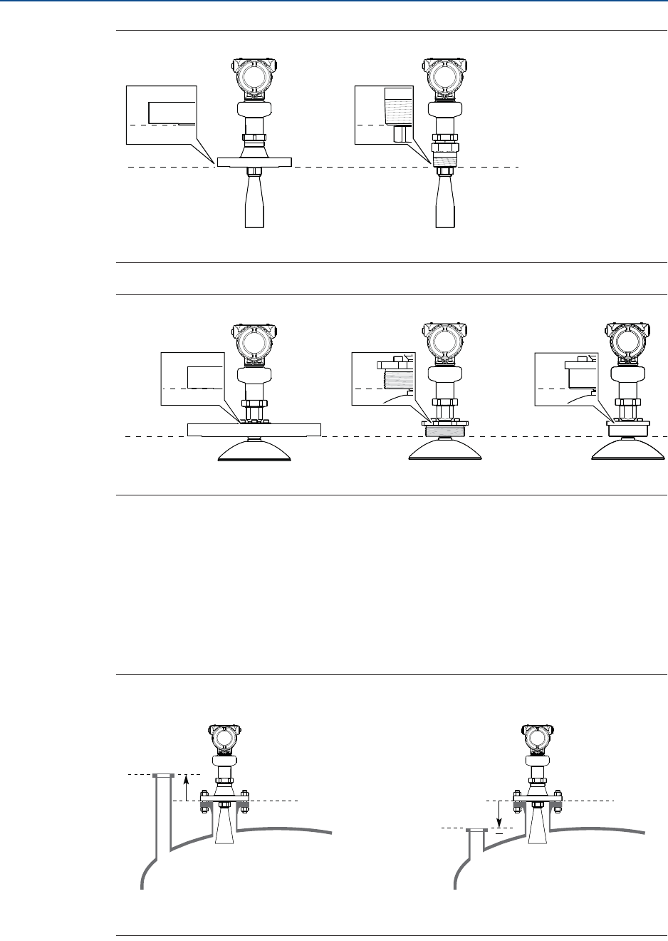
Configuration Parameters
November 2016
Reference Manual
00809-0100-4408, Rev AA
169
Configuration Parameters
PRELIMINARY
Figure C-10. Device Reference Point for Cone Antennas
A. Device Reference Point
Figure C-11. Device Reference Point for Parabolic Antennas with Swivel Mount
A. Device Reference Point
Reference offset
Distance between the Device Reference Point and the Tank Reference Point (typically the
upper side of a customer plug where levels can be manually measured).
The Reference Offset parameter can be used to specify your own reference point, for
example when the measured level by the transmitter should correspond with the level value
obtained by hand-dipping.
Figure C-12. Reference Offset
A. Tank Reference Point
B. Device Reference Point
A
A
+
B
A
A
B
Reference Offset > 0 Reference Offset < 0
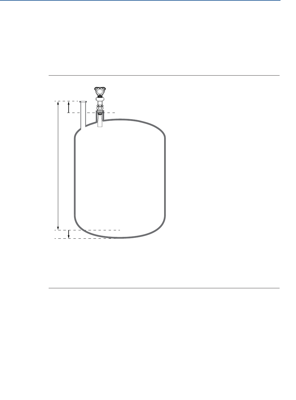
Configuration Parameters
November 2016
Reference Manual
00809-0100-4408, Rev AA
170 Configuration Parameters
PRELIMINARY
Bottom offset
The Bottom Offset is defined as the distance between Zero Level and the tank bottom. The
default value is zero.
If the Zero Level is not located at the tank bottom, then enter a Bottom Offset. It is needed
for the transmitter to know the position of the tank bottom echo and for correct volume
calculations.
Figure C-13. Bottom Offset
A. Tank Reference Point
B. Reference Offset
C. Device Reference Point
D. Reference Height
E. Zero Level
F. Bottom Offset
Height of tank
The vertical distance between tank bottom and tank roof. For a horizontal cylinder or
spherical tank, this is the diameter of the tank.
Width of tank
The horizontal distance between tank ends. For a vertical cylinder, this is the diameter of
the tank. The width of tank is also the shortest horizontal side of a box-shaped (cubical)
tank.
Length of tank
The longest horizontal side of a cubical tank.
A
C
B
D
EF
+
+

Configuration Parameters
November 2016
Reference Manual
00809-0100-4408, Rev AA
171
Configuration Parameters
PRELIMINARY
Top shape height
The height of the shape on tank top (typically from shape floor to cap top, measured at
cylinder center line).
Bottom shape height
The height of the shape at tank bottom (typically from shape floor to shape bottom,
measured at cylinder center line).
End shape length
The width of the spherical cap at tank end (measured at cylinder center line).
Show negative level as zero
When this setting is selected and the product surface is at or below Zero Level, the level
measurement output will be zero.
C.3.2 Environment
Product type
The media used in the monitored process.
Process conditions
Foam
This parameter should be used if there is, or may be, surface foam. When setting this
parameter, the transmitter is optimized for conditions with weak and varying surface echo
amplitudes, which is typical for presence of surface foam.
Turbulent surface
Set this parameter to improve the performance of the transmitter when there are small and
local rapid level changes caused by surface turbulence. The reason for the turbulence might
be splash loading, agitators, mixers, or boiling product.
Maximum level rate
Fastest rate that may occur in the monitored process to (partially) fill or empty this tank.
Note that product level rate may be higher during upset conditions.
Product dielectric range
Enter the range of the dielectric constant for the product in the tank. If the range is not
known, or if the product in the tank is changed on a regular basis, then select Default.
C.3.3 Volume
Select if the volume measurement should be calculated from the configured tank
dimensions or a strapping table.
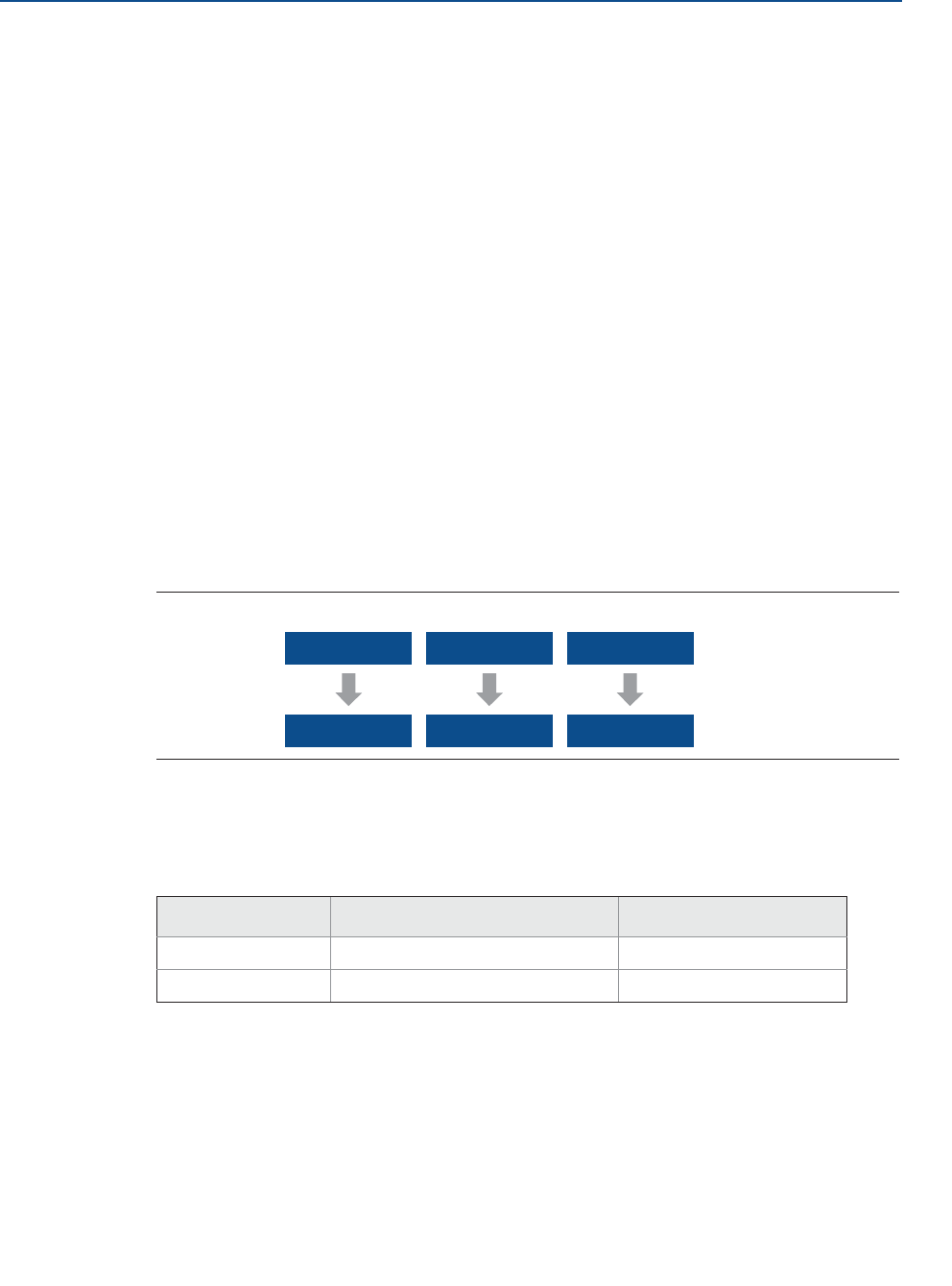
Configuration Parameters
November 2016
Reference Manual
00809-0100-4408, Rev AA
172 Configuration Parameters
PRELIMINARY
Strapping tables can be used for irregularly shaped tanks, to eliminate errors due to bulging
when product is added to a tank, or if a pre-defined tank type does not provide sufficient
accuracy.
Strapping table
Strapping table requires entering level-volume pairs in a table (maximum 50 points). Use
most of the strapping points in regions where the tank shape is non-linear. Starting at the
bottom of the tank, for each new point, enter the total volume up to the specified level
value.
Volume offset
Use this parameter to add a volume to each calculated volume value, for example a sump
volume below the Zero Level in the tank.
C.3.4 Scaled variable(1)
The scaled variable can be used to convert a transmitter variable into an alternative
measurement, such as flow, mass, or calibrated level (e.g. 5 point verification).
The scaled variable is defined by creating a table of transmitter variables and corresponding
output variables. A maximum of 50 points can be specified. Between the points linearly
interpolated values are calculated.
Figure C-14. Scaled Variable Examples
As an example, consider a product with a density of 900 kg/m3. In this case, the volume to
mass conversion is given by the following table:
Table C-1. Example of Scaled Variable Table
Scaled variable name
Name of the scaled variable. It is recommended to enter a short name to fit into the LCD
display area.
Scaled variable unit
Units of measurement of the scaled variable.
1. Only for transmitters ordered with Smart Diagnostics Suite (option code DA1).
Number Input value (volume) Output value (mass)
10 m30 ton
2100 m390 ton
Input Variable: Level Volume Level
Output Variable: Flow Mass Calibrated Level
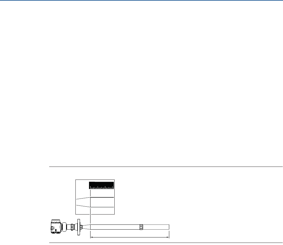
Configuration Parameters
November 2016
Reference Manual
00809-0100-4408, Rev AA
173
Configuration Parameters
PRELIMINARY
Number of scaled values
Number of values in the scaled variable table.
Input variable
Select the input variable to use for scaled variable calculation.
C.3.5 Antenna
Antenna type
The transmitter is designed to optimize measurement performance for each available
antenna type. This parameter is pre-configured at factory; it only needs to be set if the
antenna is changed to another type, or if you have installed a spare transmitter.
Antenna extension length
This parameter is pre-configured at factory. The Antenna Extension Length (see
Figure C-15) must be changed if the extension is shortened, or if you have ordered a spare
transmitter head. Enter zero (0) for antennas without extensions.
Figure C-15. Antenna Extension Length (L)
User defined antenna options
Parameters for user defined antenna. These settings are typically provided by factory and
should only be modified for customized antennas.
When a Rosemount 5408 transmitter head is mounted on a Rosemount 5402 antenna, refer
to Table C-2 and Table C-3 for antenna parameters.
L
123
0

Configuration Parameters
November 2016
Reference Manual
00809-0100-4408, Rev AA
174 Configuration Parameters
PRELIMINARY
Table C-2. Rosemount 5402 Antenna Parameters, Open Tanks (Free Propagation)
Table C-3. Rosemount 5402 Antenna Parameters, Still Pipes/Chambers
Upper null zone
The Upper Null Zone defines how close to the transmitter's reference point a level value is
accepted. You can extend this value to block out disturbing echoes close to the antenna, for
example from the tank nozzle or bypass well inlet. See “Handling disturbances at top of
tank” on page 99 for more information.
Note
Make sure the 20 mA value is below the Upper Null Zone. Measurements are not performed
within the Upper Null Zone (UNZ).
C.3.6 Advanced
Calibration offset
Difference between surface distance measured by transmitter and the same distance
measured by e.g. hand-dipping with a measurement tape. A positive Calibration Offset
value will increase the presented level value.
It is recommended to run the Verify Level tool to match the product level reported by the
transmitter to a reference measurement, see “Verify Level” on page 66.
Antenna type Tank connection length Antenna
gain
Nearzone
threshold
(mV)
Nearzone range Upper Null Zone(1)
1. Default setting. The Upper Null Zone may need to be increased if there are disturbance echoes in the region close to the antenna.
ft mft mft m
2-in. cone 0.502 0.153 2.3 2260 4.23 1.29 0.541 0.165
3-in. cone 0.495 0.151 1.35 1410 3.31 1.01 0.492 0.15
4-in. cone 0.499 0.152 0.9 990 3.87 1.18 0.738 0.225
2-in. process seal 0.906 0.276 2.9 2780 4.86 1.48 0.492 0.15
3-in. process seal 1.168 0.356 1.5 2330 3.51 1.07 0.492 0.15
4-in. process seal 1.296 0.395 0.8 810 3.64 1.11 0.492 0.15
Antenna type Tank connection length Antenna
gain
Nearzone
threshold
(mV)
Nearzone range Upper Null Zone(1)
1. Default setting. The Upper Null Zone may need to be increased if there are disturbance echoes in the region close to the antenna.
ft mft mft m
2-in. cone 0.502 0.153 0.125 400 2.6 0.8 0.541 0.165
3-in. cone 0.495 0.151 0.125 400 2.6 0.8 0.492 0.15
4-in. cone 0.499 0.152 0.125 400 2.6 0.8 0.738 0.225
2-in. process seal 0.906 0.276 0.125 400 3.3 1.0 0.492 0.15
3-in. process seal 1.168 0.356 0.125 400 3.3 1.0 0.492 0.15
4-in. process seal 1.296 0.395 0.125 400 3.3 1.0 0.492 0.15

Configuration Parameters
November 2016
Reference Manual
00809-0100-4408, Rev AA
175
Configuration Parameters
PRELIMINARY
User defined variable setup(1)
Name
Name of the user defined variable. It is recommended to enter a short name to fit into the
LCD display area.
Input register
Enter the number of the input register that contains value of the user defined variable. See
Table C-4 for a list of suitable input registers.
Table C-4. List of Input Registers to the User Defined Variable
1. Only for transmitters ordered with Smart Diagnostics Suite (option code DA1).
Variable Register Description
Min Electronics Temperature 20146 Minimum electronics temperature measured by
the device (°C)
Max Electronics Temperature 20148 Maximum electronics temperature measured by
the device (°C)
Surface Update Relation 21028 Determines how robust the surface echo
measurement is (0 to 1). A decreasing value may
be used to identify turbulence or foam in the
process.
Min Signal Quality 21034 Minimum signal quality measured by the
transmitter since last signal quality reset. Signal
quality calculation must be enabled to use this
variable.
Max Signal Quality 21036 Maximum signal quality measured by the device
since last signal quality reset. Signal quality
calculation must be enabled to use this variable.
Distance to Upper Surface 21042 Distance to the upper product surface (m) when
measuring on multiple products in the tanks.
Double Surface function must be enabled to use
this variable.
Distance to Lower Surface 21044 Distance to the lower product surface (m) when
measuring on multiple products in the tanks.
Double Surface function must be enabled to use
this variable.
Surface Signal/Noise Ratio 21054 Ratio between surface echo signal strength and
signal noise (dB). A high value (>20 dB) indicates
very good margin to noise.
Product Dielectric Constant 22800 Square root of the product dielectric constant
estimated by the transmitter when the Bottom
Projection function is enabled.
The product dielectric constant is calculated
when both the bottom and surface echoes are
found by device, and when surface echo is within
the Max Projection Distance. Product dielectric
constant estimation is frozen if any of these
conditions are not fulfilled.

Configuration Parameters
November 2016
Reference Manual
00809-0100-4408, Rev AA
176 Configuration Parameters
PRELIMINARY
Unit
Units of measurement of the user defined variable.
More advanced options(1)
By default, these parameters are automatically set based on current configuration. It is
recommended that these parameters should remain at the default settings, unless there is a
good understanding of the function and capability of the parameters.
Empty tank handling
The Empty Tank Handling functions handle situations when the surface echo is close to the
tank bottom.
Empty tank detection area
The Empty Tank Detection Area defines a range where it is accepted to lose the echo from
the product. If the echo is lost in this range, the tank is considered empty and the level is
presented as 0.
When the tank is empty, the transmitter looks in this range for the product surface. When a
new echo is found in this range, it is considered to be the product surface. Therefore, if there
are disturbance echoes in this area, they may need to be filtered out.
This function requires the Bottom echo visible when tank is empty parameter to be
disabled.
Bottom echo visible when tank is empty
Only enable this parameter if the bottom echo is visible when tank is empty. By setting this
parameter, the bottom echo will be treated as a disturbance echo to facilitate tracking of
weak surface echoes close to the tank bottom (see “Enable bottom echo visible when tank
is empty” on page 100).
Tank bottom projection
The Tank Bottom Projection is used to enhance measurement performance near the
bottom of the tank. When the tank bottom echo is strong (typical for flat tank bottoms)
and the dielectric constant of the product is low (e.g. oil), the transmitter may lock on the
bottom echo and report a false level measurement (empty tank). This problem can be
solved by using the Tank Bottom Projection function. See “Tracking of weak surface echoes
close to tank bottom” on page 100 for further instructions.
Bottom product dielectric constant
Enter the product dielectric constant for the product in the bottom of the tank.
Maximum projection distance
This defines the range where the function is active. Enter the maximum distance from the
zero level (tank bottom).
Minimum tank bottom amplitude
1. Only available in Rosemount Radar Master.

Configuration Parameters
November 2016
Reference Manual
00809-0100-4408, Rev AA
177
Configuration Parameters
PRELIMINARY
Enter the minimum allowed amplitude for the echo from the tank bottom before this
function is activated.
Echo tracking
Surface echo tracking
Use these settings to configure how the transmitter should keep track of the surface. These
are advanced settings. Normally, they should not be changed.
Search window size
This parameter defines a window centered at the current surface position where new
surface echo candidates can be selected. The size of the window is ±Search Window Size.
Echoes outside this window will not be considered as surface echoes.
If there are rapid level changes in the tank, the value of the Search Window Size can be
increased to prevent the transmitter from missing level changes. On the other hand, a large
value may cause the transmitter to select an invalid echo as the surface echo.
Track first echo
Select the Track First Echo check box if the first echo above threshold always should be
considered as the surface echo (see “Handling ghost echoes in still pipes” on page 102).
Double surface handling
If there are multiple products in the tank, the Double Surface Handling function can be
manually set to allow user to select if the upper or lower product should be used as output.
Track upper surface
Track upper surface when there are multiple products in the tank (for example thin oil layer
on top of water).
Track lower surface
Track the lower product surface, such as the interface when there are multiple products in
the tank, or the product surface instead of a foam layer.
Upper product dielectric constant
Enter the dielectric constant for the upper product. A more precise value results in better
accuracy for the lower surface level.
Double bounce handling
Use this function to prevent transmitter from locking on strong double bounce echoes (may
occur in spherical and horizontal cylinder tanks). See “Handling strong double bounce
echoes” on page 103 for more information.
Overfill prevention
The Overfill Prevention function adds an extra layer of protection to prevent tank overfills.
The function uses an independent echo logic algorithm to identify the surface echo close to
the top of the tank.
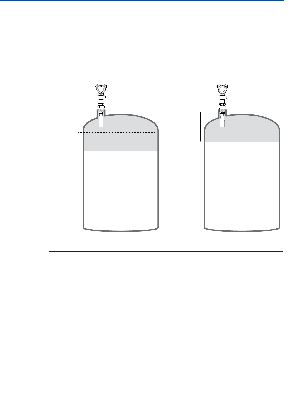
Configuration Parameters
November 2016
Reference Manual
00809-0100-4408, Rev AA
178 Configuration Parameters
PRELIMINARY
In the unlikely event there is a conflict between the normal and the overfill prevention echo
logic, the Overfill Prevention function will have a precedence in determining the position of
the surface. The transmitter will then output this new value, or generate an alarm if the
normal echo logic is not able to find the surface echo at the new position.
The Overfill Prevention Range defines the lower end of the range in which the function
operates. The range is configurable. See Figure C-16 for default factory settings.
Figure C-16. Overfill Prevention Range
A. Device Reference Point
B. Overfill Prevention Range
Expert options
Use the expert options to view input registers and to view and edit holding registers.
Note
Instructions for how to use Expert options are typically provided by factory and should only
be modified if required.
C.4 Alert setup
C.4.1 Alarm delay
The Alarm Delay parameter controls the maximum time from when a fault condition is
detected until it is annunciated. Conditions that are cleared within the time specified by
Alarm Delay time will not be annunciated.
Rosemount 5408:SIS Rosemount 5408
0% (4 mA)
100% (20 mA)
80% B
A
20 in. (500 mm)
B
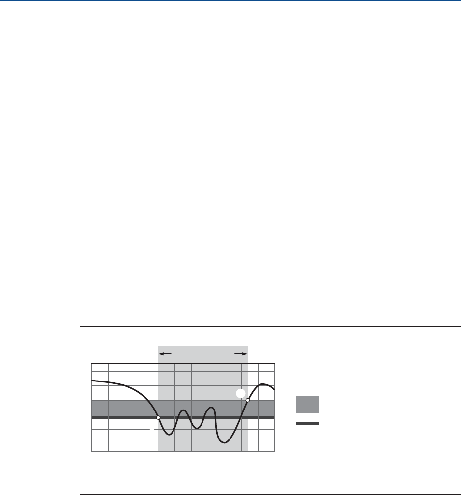
Configuration Parameters
November 2016
Reference Manual
00809-0100-4408, Rev AA
179
Configuration Parameters
PRELIMINARY
It is recommended to keep Alarm Delay at default value (30 seconds) and only decrease it if
a shorter detection time is required. Alarm Delay can be increased to increase robustness
and avoid nuisance alarms.
Alarm Delay is applicable for diagnostic tests that run frequently (typically every
measurement cycle). Alarm Delay is not applicable for critical hardware failures that will be
annunciated as soon as they are detected by the device.
C.4.2 Signal quality alert(1)
Signal Quality is a measure of the product surface echo amplitude compared to the surface
threshold and noise.
The Signal Quality spans from 0 to 10. A low value means there is a risk for losing the level
measurement. The Signal Quality may not be10 even if the antenna is clean. The value
depends on antenna type, application conditions, configured surface threshold, as well as
the condition of the antenna.
Build up on the antenna and different surface conditions are factors that can result in a low
Signal Quality value. By setting an alert, the Signal Quality value can be used to schedule
maintenance to clean the antenna, fine-tune the surface threshold, or detect and monitor
adverse surface conditions such as turbulence or foam.
Suitable alert limits vary from application to application. Appropriate value can be
determined by logging Signal Quality over time and viewing maximum/minimum values.
The Signal Quality Alert limit should be at least 1, but a better guideline is 2-3.
Figure C-17. Signal Quality Alert
A. The Signal Quality drops below the alert limit and an alert message is triggered.
B. The alert message is reset once the Signal Quality value rises above the Deadband range.
Limit
The Signal Quality value that will trigger the alert.
Deadband
The Deadband is a buffer zone so the alerts do not toggle on and off when the Signal Quality
fluctuates around the alert limit. The alert is set when value falls below the alert limit. The
alert is then cleared when value rises above the Deadband range.
1. Only for transmitters ordered with Smart Diagnostics Suite (option code DA1).
A
B
Alert ON
Time
Signal Quality
Deadband
Limit
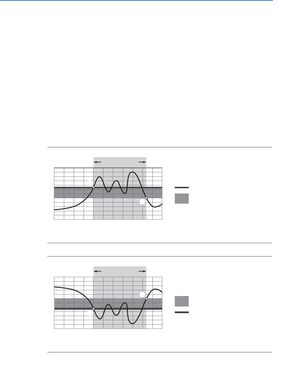
Configuration Parameters
November 2016
Reference Manual
00809-0100-4408, Rev AA
180 Configuration Parameters
PRELIMINARY
C.4.3 High/low user defined alert
A high and low alert may be established to output an alert message when the measurement
readings exceed the specified limits.
Variable
Select the transmitter variable to use for the alert.
Limit
The value that will trigger the alert.
Deadband
The Deadband is a buffer zone so the alerts do not toggle on and off when the
measurement value fluctuates around the alert limit. The alert is set when the value
exceeds the alert limit. The alert is then cleared when the value falls outside the Deadband
range, see Figure C-18 and Figure C-19.
Figure C-18. High User Defined Alert
A. The alert is active when the values rises above the alert limit.
B. The alert turns off when the value falls below the deadband.
Figure C-19. Low User Defined Alert
A. The alert is active when the values falls below the alert limit.
B. The alert turns off when the value rises above the deadband.
A
B
High Alert ON
Time
User Defined Variable
Limit
Deadband
A
B
Low Alert ON
Time
User Defined Variable
Deadband
Limit

Reference Manual
00809-0100-4408, Rev AA
November 2016
PRELIMINARY
Global Headquarters
Emerson Process Management
6021 Innovation Blvd.
Shakopee, MN 55379, USA
+1 800 999 9307 or +1 952 906 8888
+1 952 949 7001
RFQ.RMD-RCC@Emerson.com
North America Regional Office
Emerson Process Management
8200 Market Blvd.
Chanhassen, MN 55317, USA
+1 800 999 9307 or +1 952 906 8888
+1 952 949 7001
RMT-NA.RCCRFQ@Emerson.com
Latin America Regional Office
Emerson Process Management
1300 Concord Terrace, Suite 400
Sunrise, FL 33323, USA
+1 954 846 5030
+1 954 846 5121
RFQ.RMD-RCC@Emerson.com
Europe Regional Office
Emerson Process Management Europe GmbH
Neuhofstrasse 19a P.O. Box 1046
CH 6340 Baar
Switzerland
+41 (0) 41 768 6111
+41 (0) 41 768 6300
RFQ.RMD-RCC@Emerson.com
Asia Pacific Regional Office
Emerson Process Management Asia Pacific Pte Ltd
1 Pandan Crescent
Singapore 128461
+65 6777 8211
+65 6777 0947
Enquiries@AP.Emerson.com
Middle East and Africa Regional Office
Emerson Process Management
Emerson FZE P.O. Box 17033
Jebel Ali Free Zone - South 2
Dubai, United Arab Emirates
+971 4 8118100
+971 4 8865465
RFQ.RMTMEA@Emerson.com
Linkedin.com/company/Emerson-Automation-Solutions
Twitter.com/Rosemount_News
Facebook.com/Rosemount
Youtube.com/user/RosemountMeasurement
Google.com/+RosemountMeasurement
Standard Terms and Conditions of Sale can be found at:
www.Emerson.com/en-us/Terms-of-Use
The Emerson logo is a trademark and service mark of Emerson Electric Co.
Rosemount and Rosemount logotype are trademarks of Emerson.
All other marks are the property of their respective owners.
© 2016 Emerson. All rights reserved.