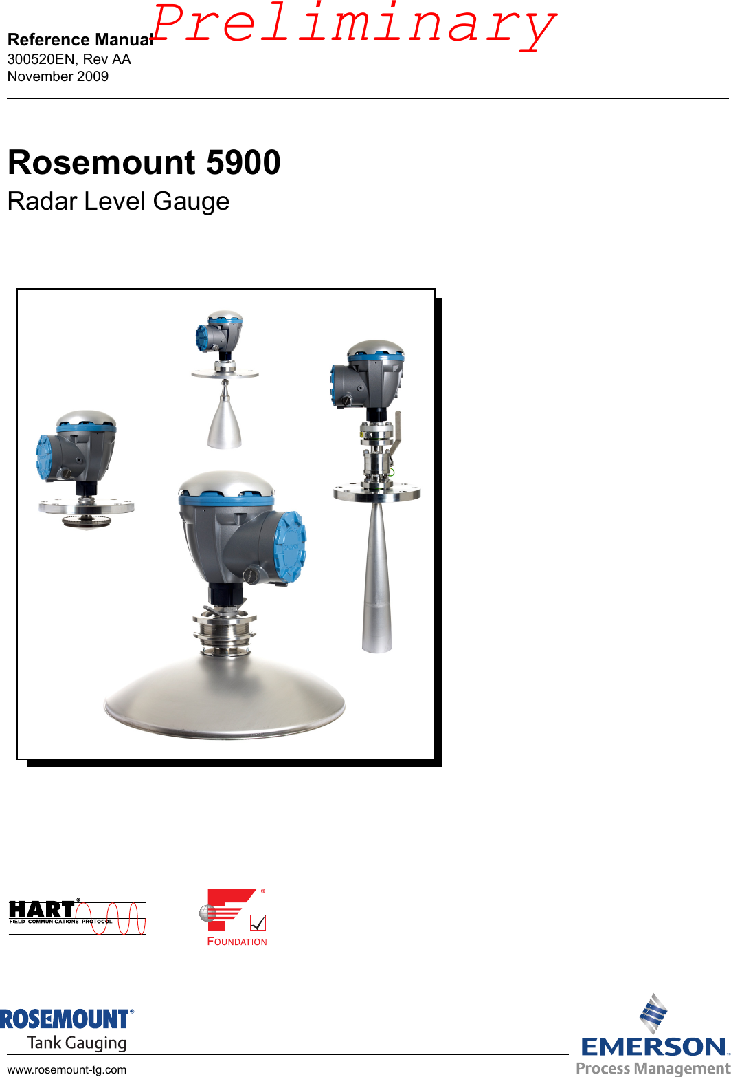
Rosemount Tank Radar 5900 Rosemount 5900S Radar Level Gauge User Manual
Rosemount Tank Radar AB Rosemount 5900S Radar Level Gauge
UserManual.wiki
>
Rosemount Tank Radar
>
5900 User Manual
>
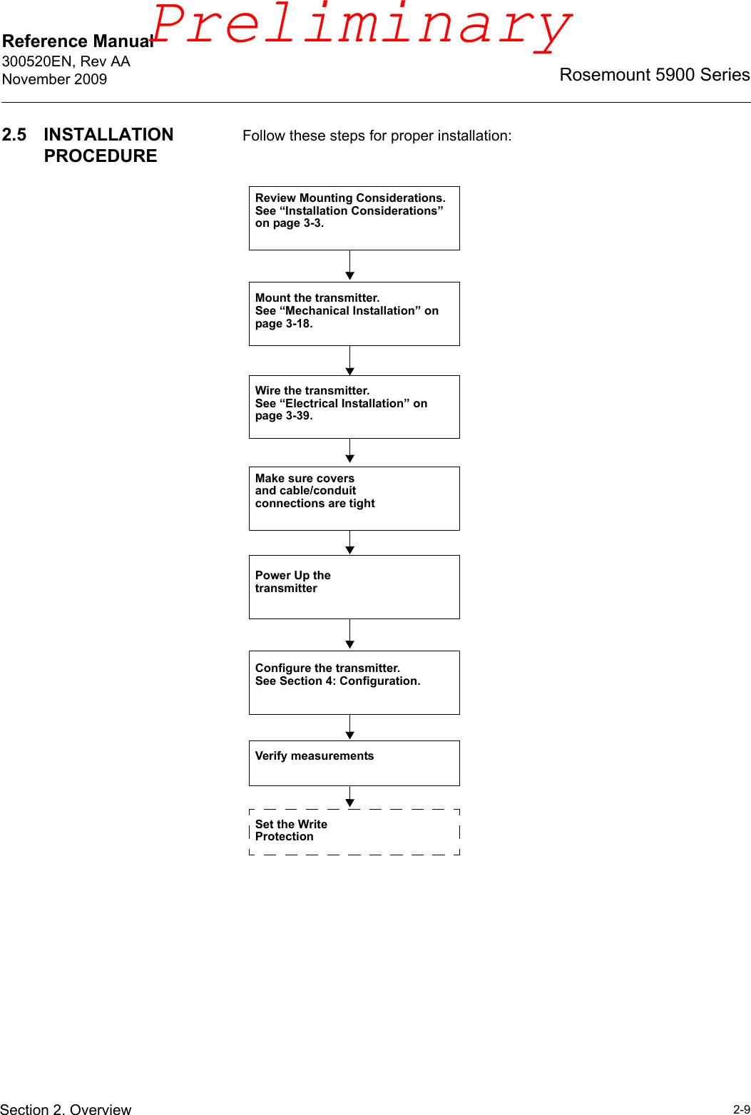
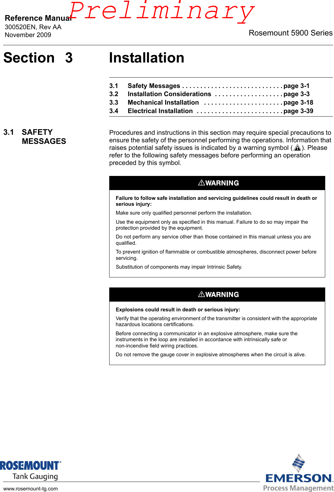
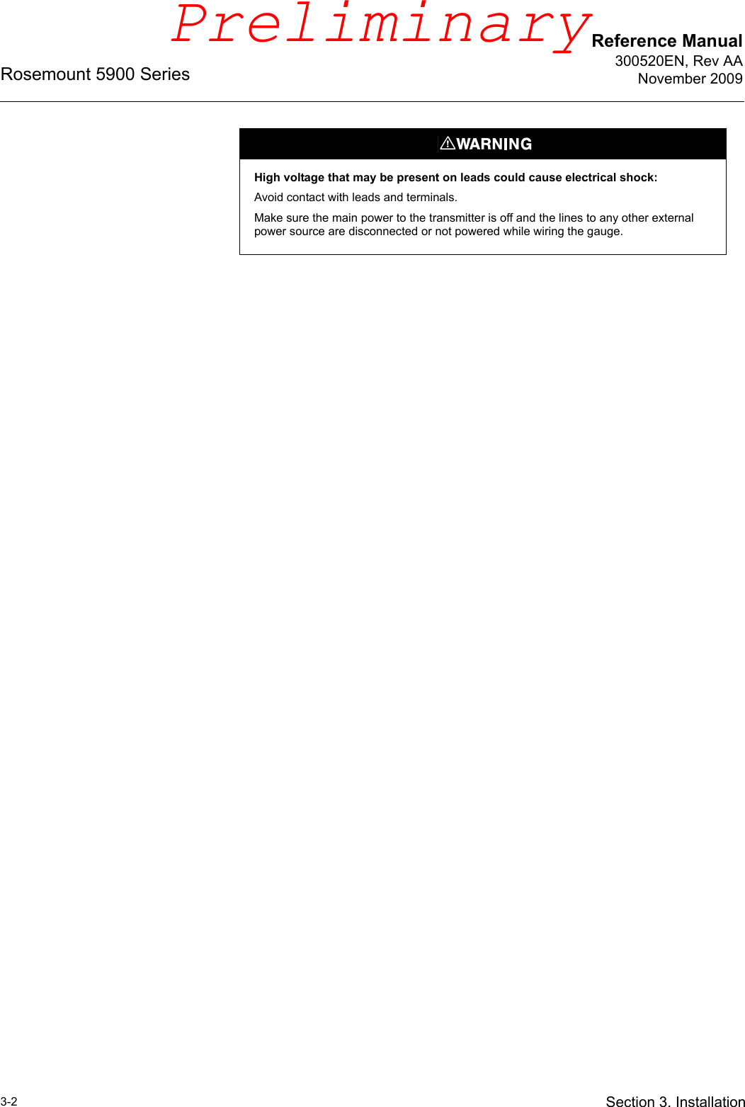
User Manual (preliminary)
Contents
1.
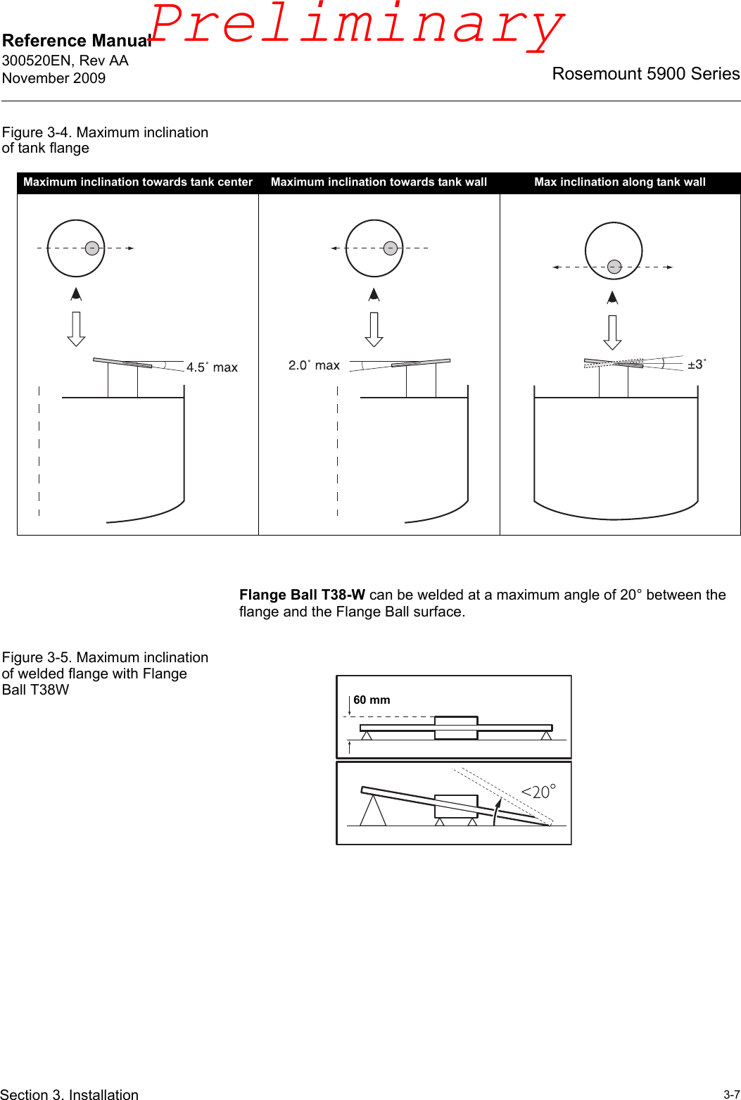
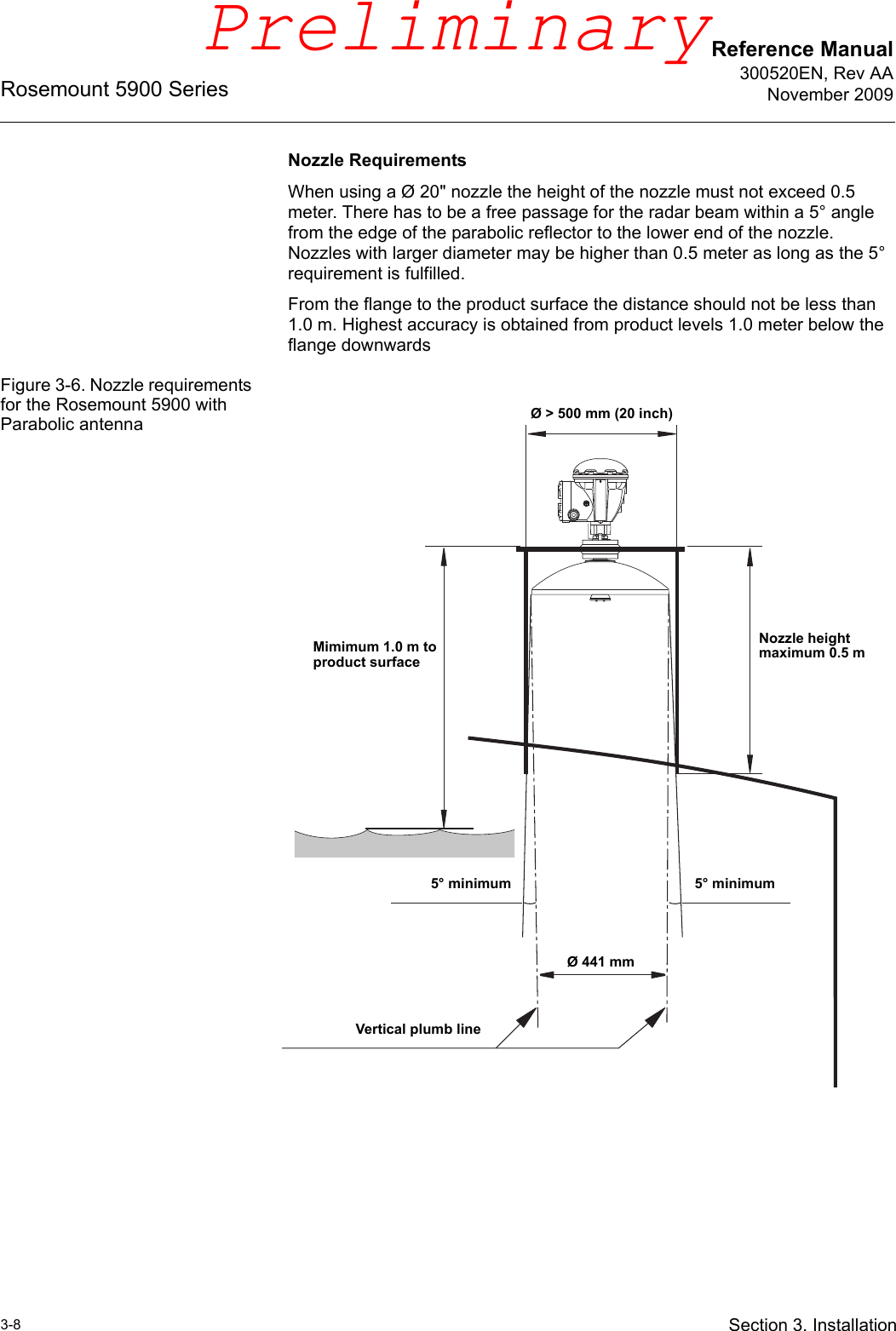
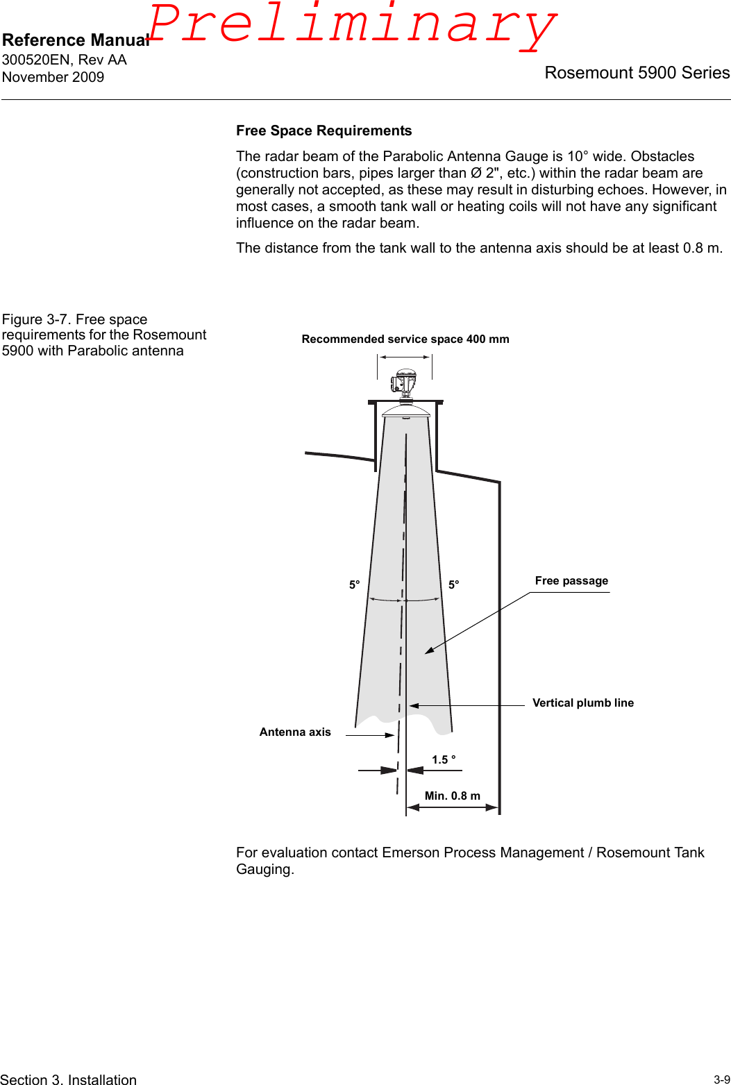
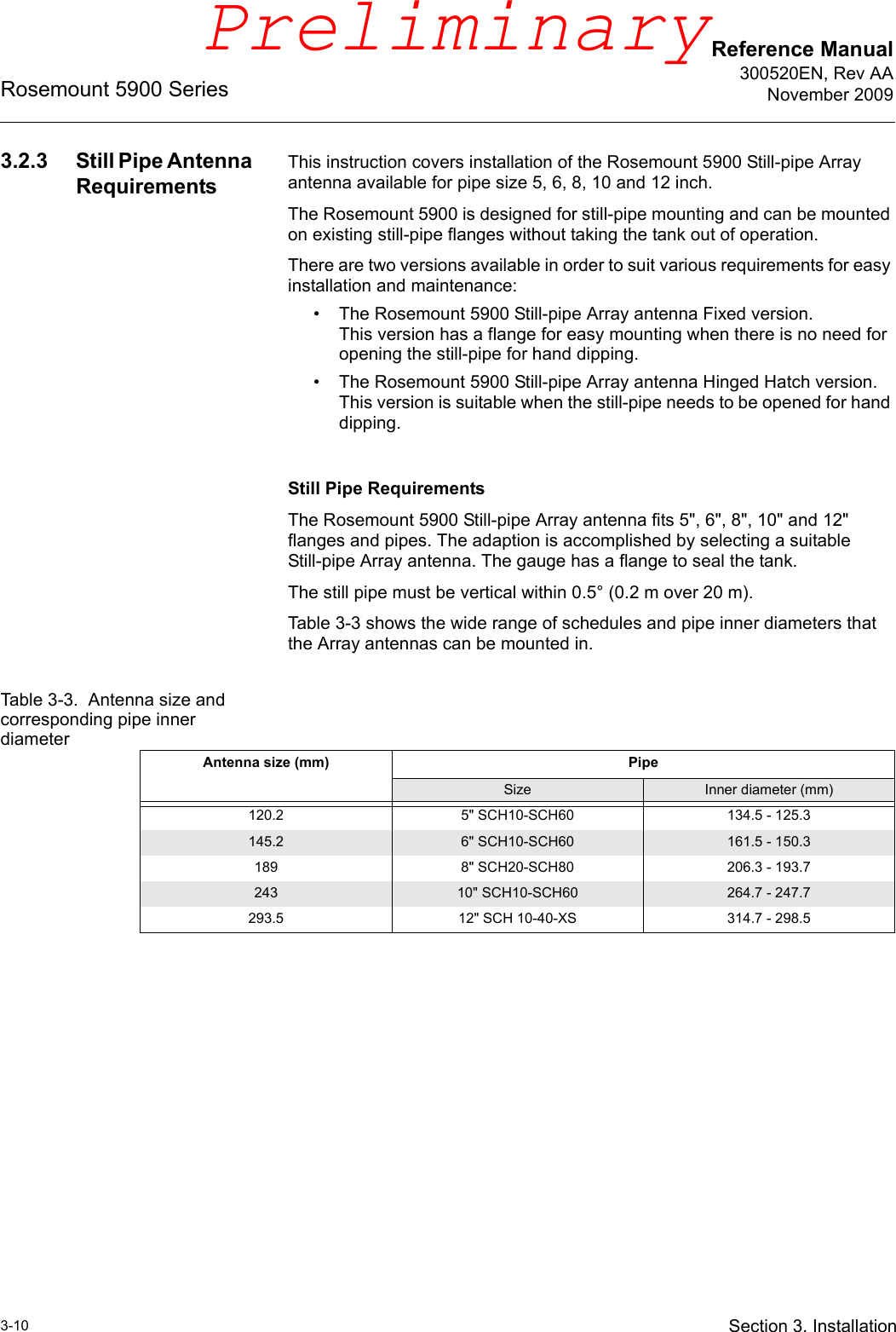
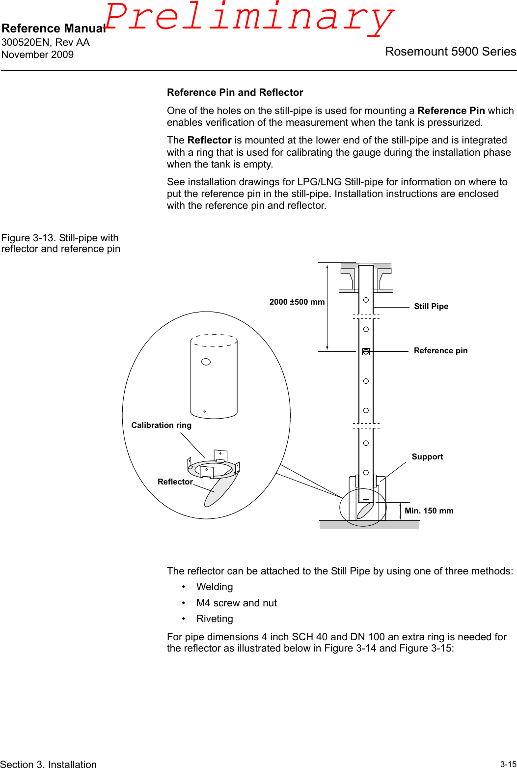
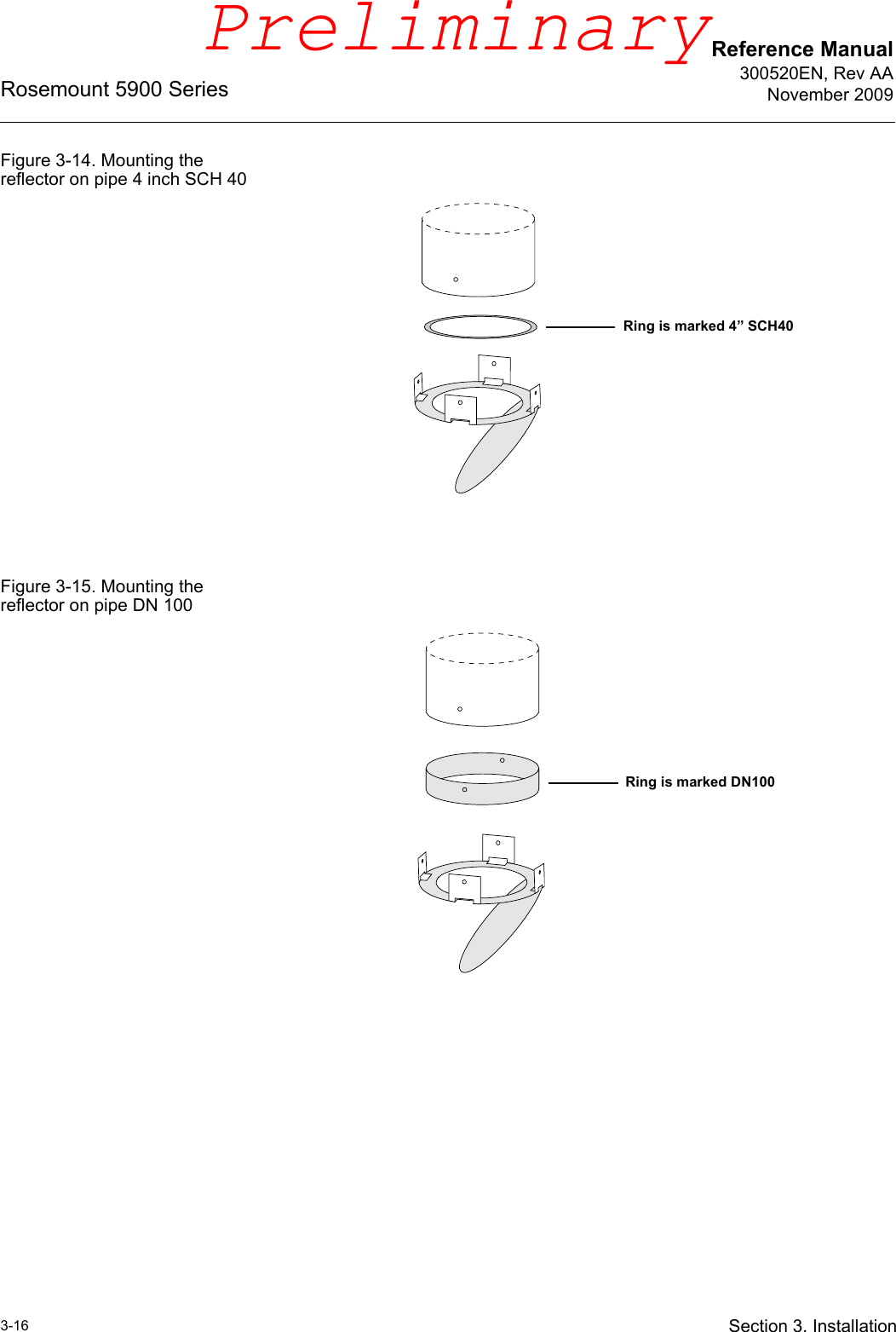
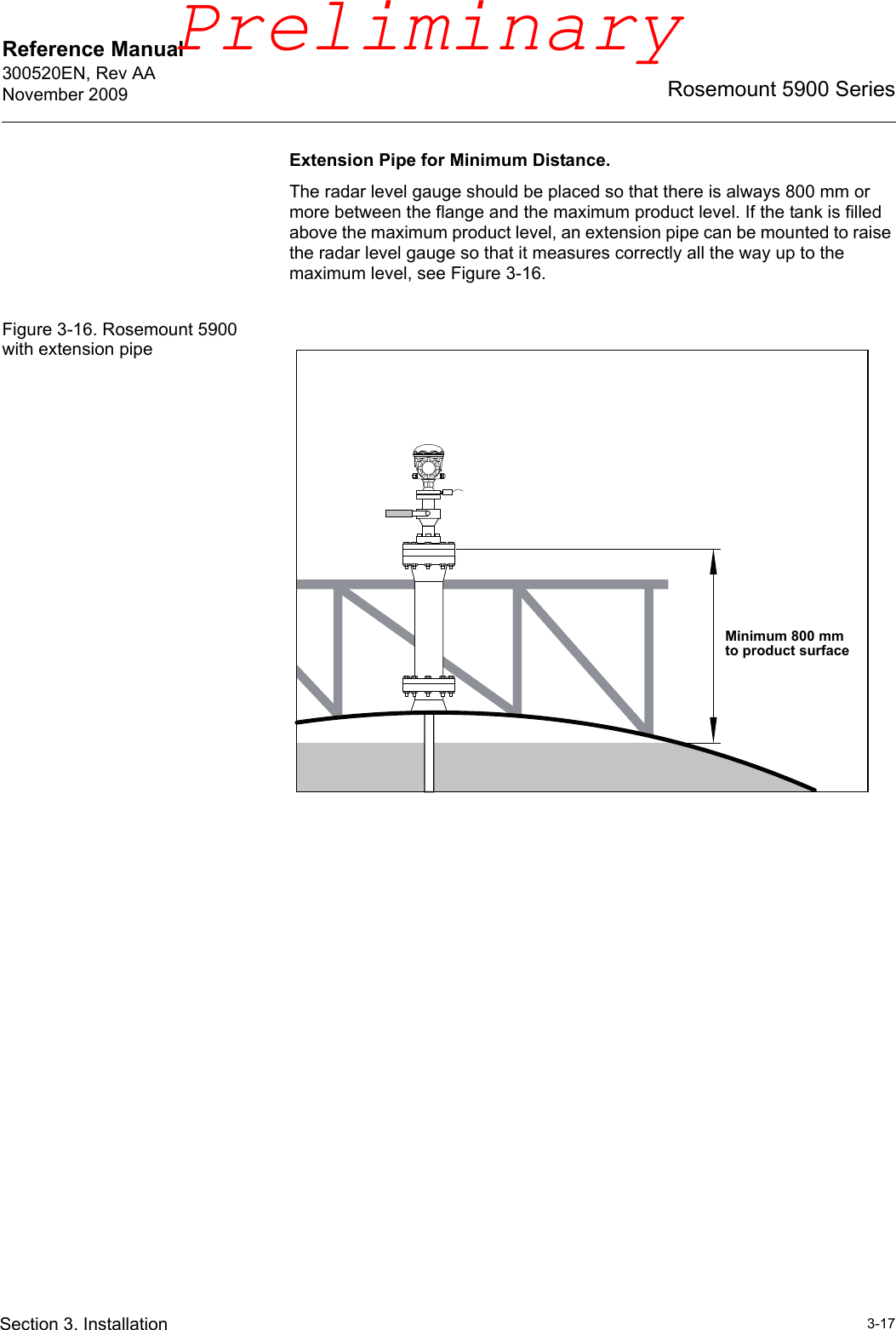
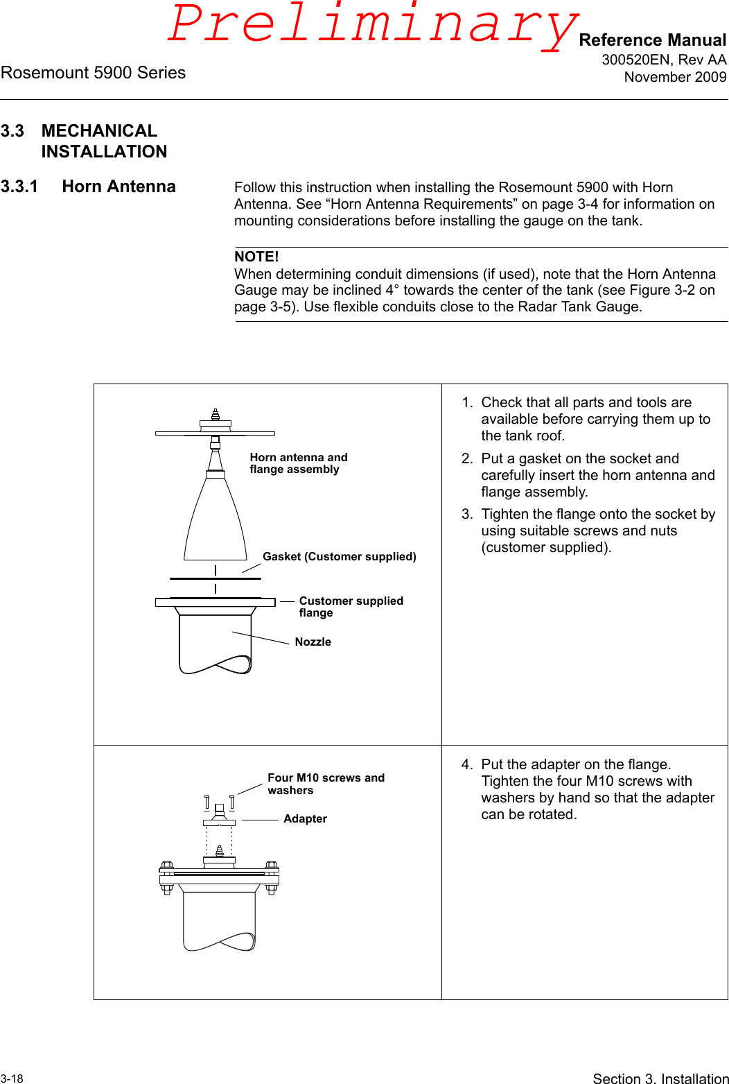
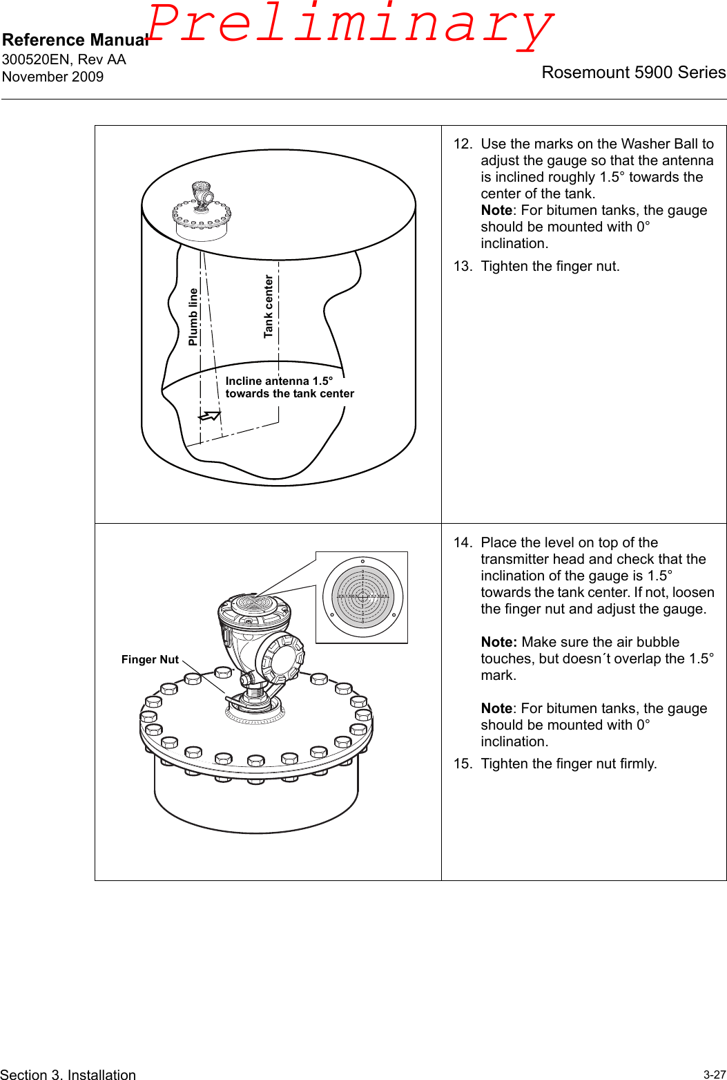
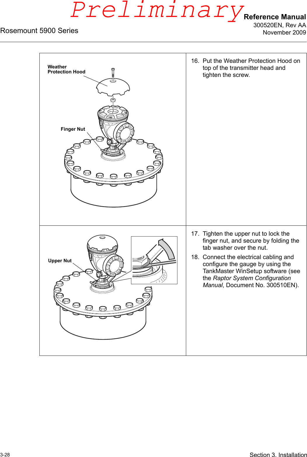
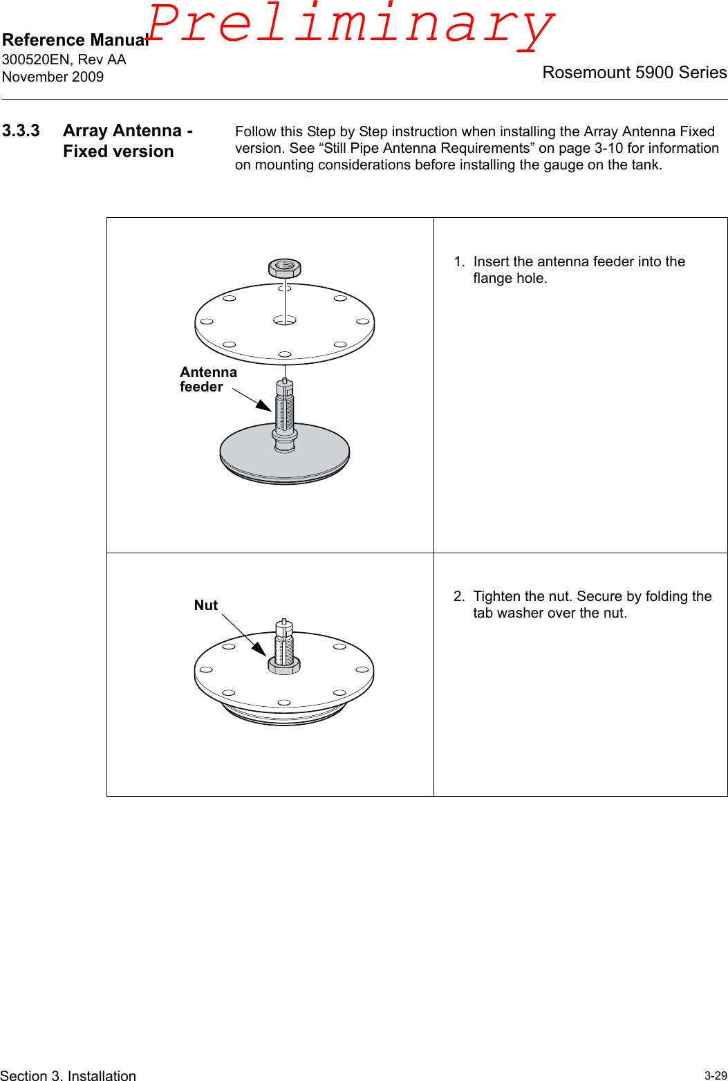
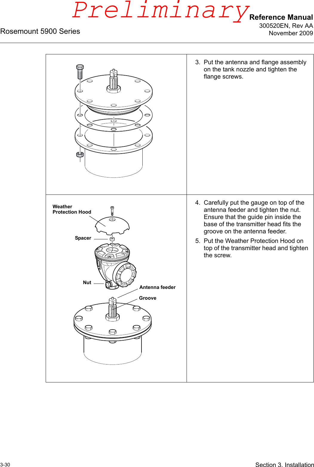
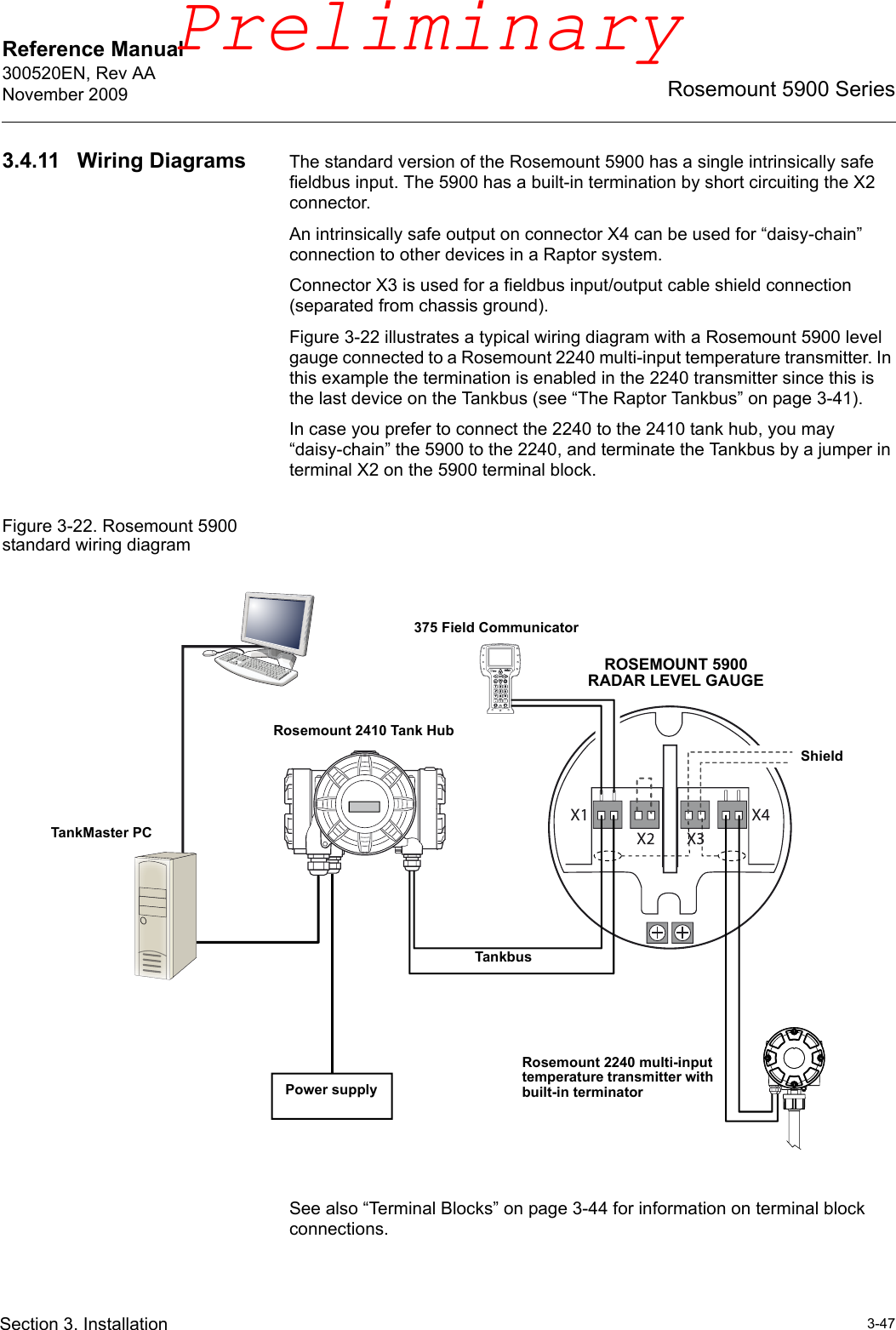
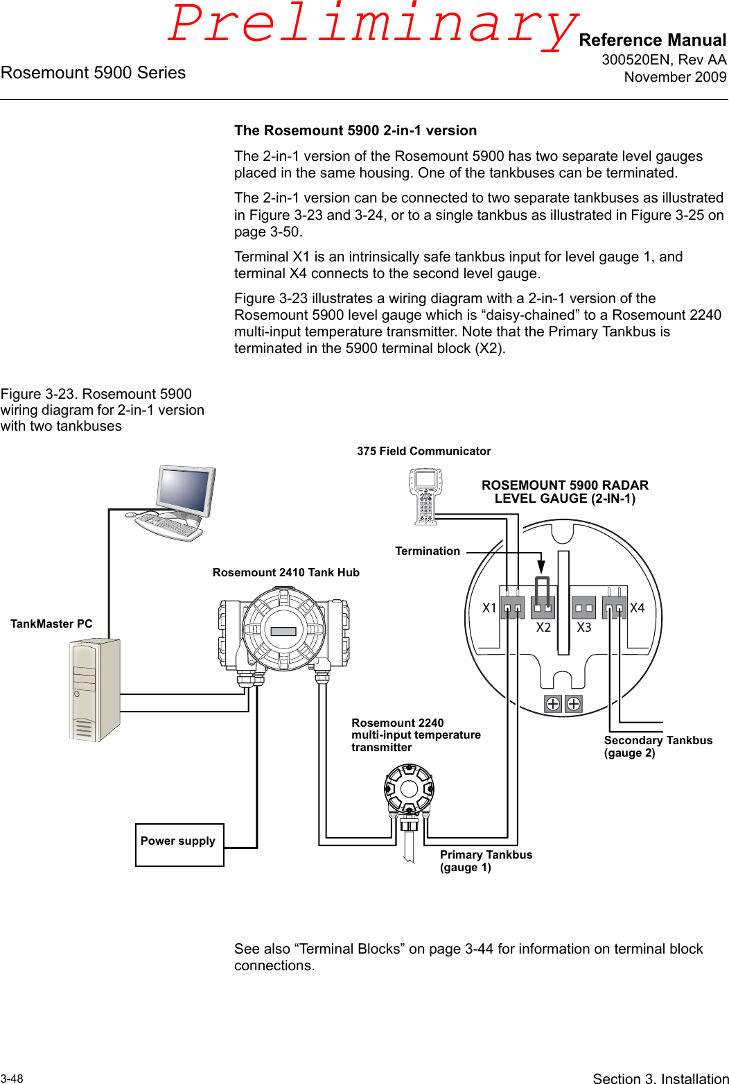
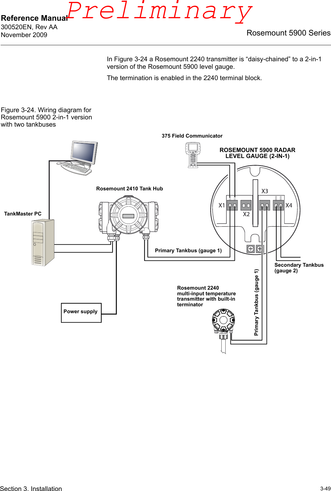
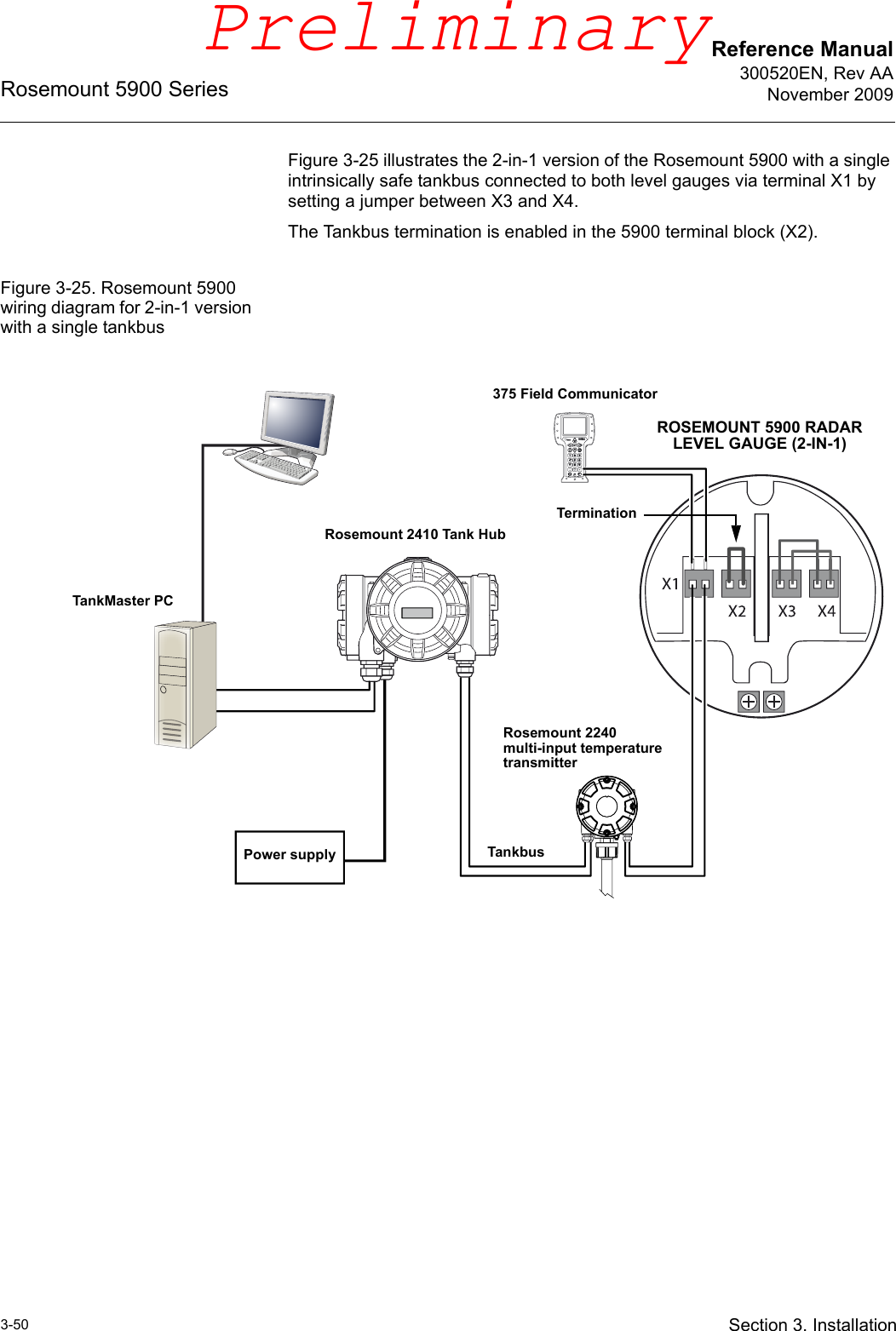
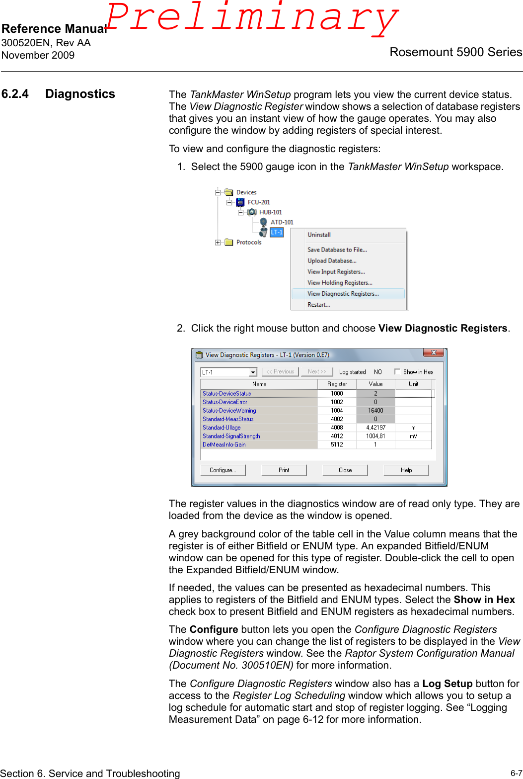
User Manual (preliminary)
2.
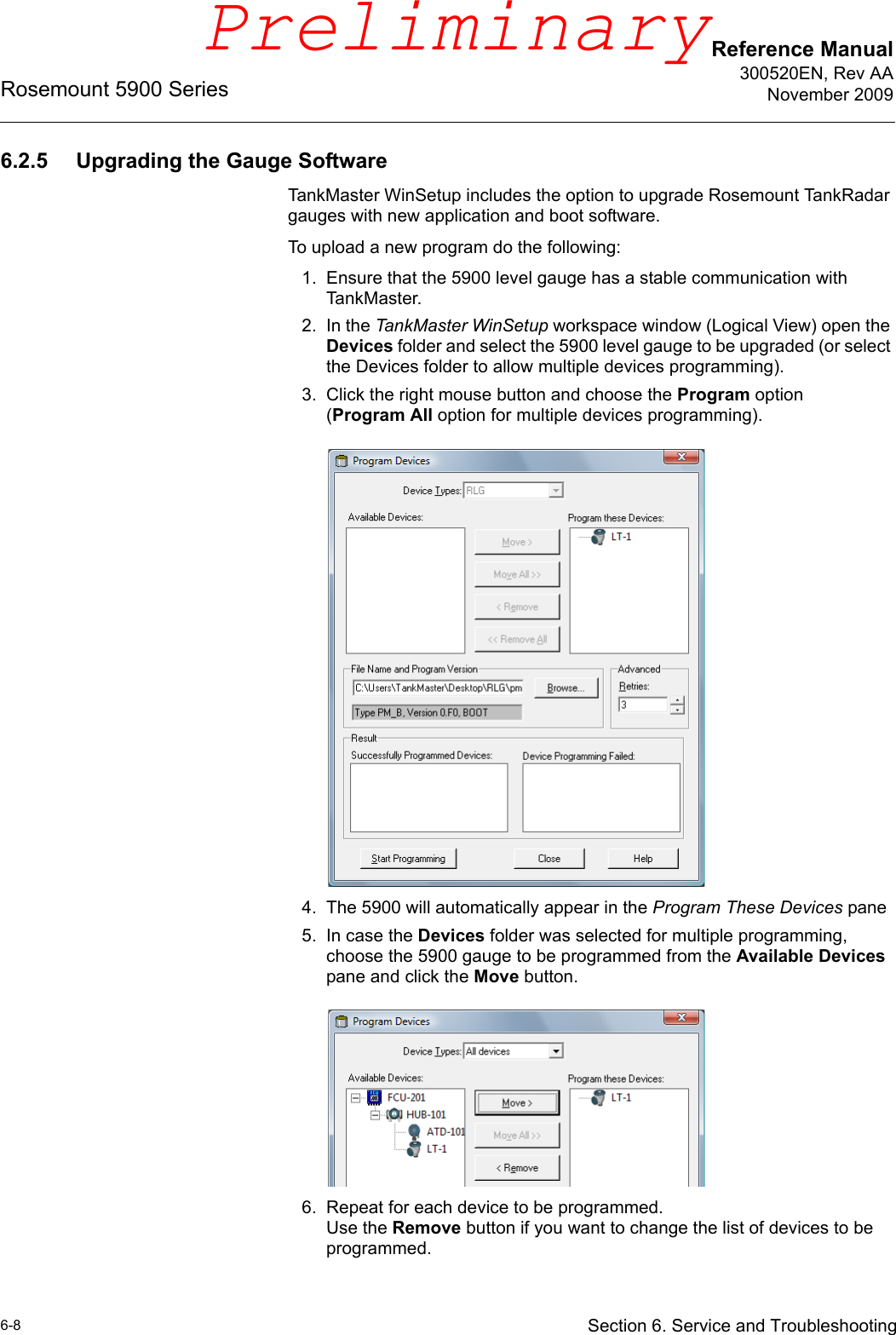
User Manual part 2
User Manual (preliminary)
Navigation menu
Upload a User Manual
Namespaces
Wiki Guide
HTML
PDF
Info
Views
User Manual
Discussion / Help
Navigation