Rosemount Tank Radar LOOPRADAR Radar Level Gauge User Manual Cover LoopRadar
Rosemount Tank Radar AB Radar Level Gauge Cover LoopRadar
UserManual.wiki
>
Rosemount Tank Radar
>
LOOPRADAR User Manual
Preliminary users manual
Navigation menu
Upload a User Manual
Namespaces
Wiki Guide
HTML
PDF
Info
Views
User Manual
Discussion / Help
Navigation


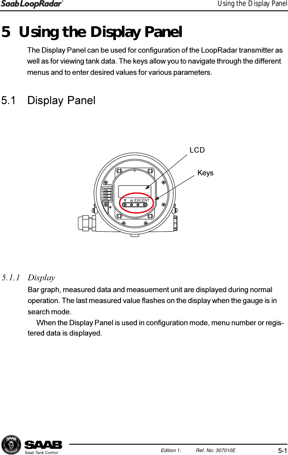
![5-3Edition 1. Ref. No: 307010EUsing the Display Panel5.2 Basic Key Parameter ListBy using the Display Panel keys you can make a complete configuration of theLoopRadar. The various settings are grouped into seven main menus:[1--] Configuration Basic configuration of tank dimensions, antenna typeand output parameter.[2--] Analog Configuration of analog output signal.[3--] Volume Specification of method for volume calculations.[4--] Calibration Only for service actions. See Appendix 1 for furtherinformation.[5--] Advanced Only for service actions. See Appendix 1 for furtherinformation.[6--] Noise Option to create a noise table in order to suppressdistinct disturbing echoes.[7--] Service Only for service actions. See Appendix 1 for furtherinformation.](https://usermanual.wiki/Rosemount-Tank-Radar/LOOPRADAR/User-Guide-99369-Page-32.png)
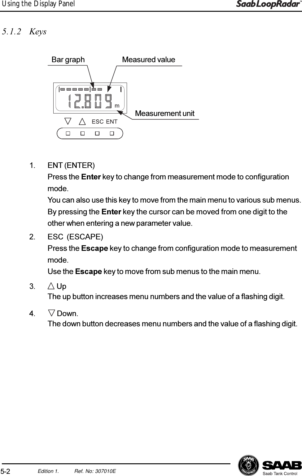
![5-5Edition 1. Ref. No: 307010EUsing the Display Panel5.3 Navigating the Display Panel MenusMeasuringDataCONFIG[1--] Analog[2--] xx[x--] Service[7--]ESCENTMeas. ModeConfig. ModeMain menuSub menuInput stageMeasuringDataCONFIG[1--]OutputParameter[1-1]ESCENTENTESCUse the ENT and ESC keys to move up and down the menu tree.Press the ENT key to switch from measurement mode to configuration mode.Press the ESC key to return to measurement mode.Use the and the keys to increment menu number.Main menuMeasurement ModeConfiguration Mode](https://usermanual.wiki/Rosemount-Tank-Radar/LOOPRADAR/User-Guide-99369-Page-34.png)
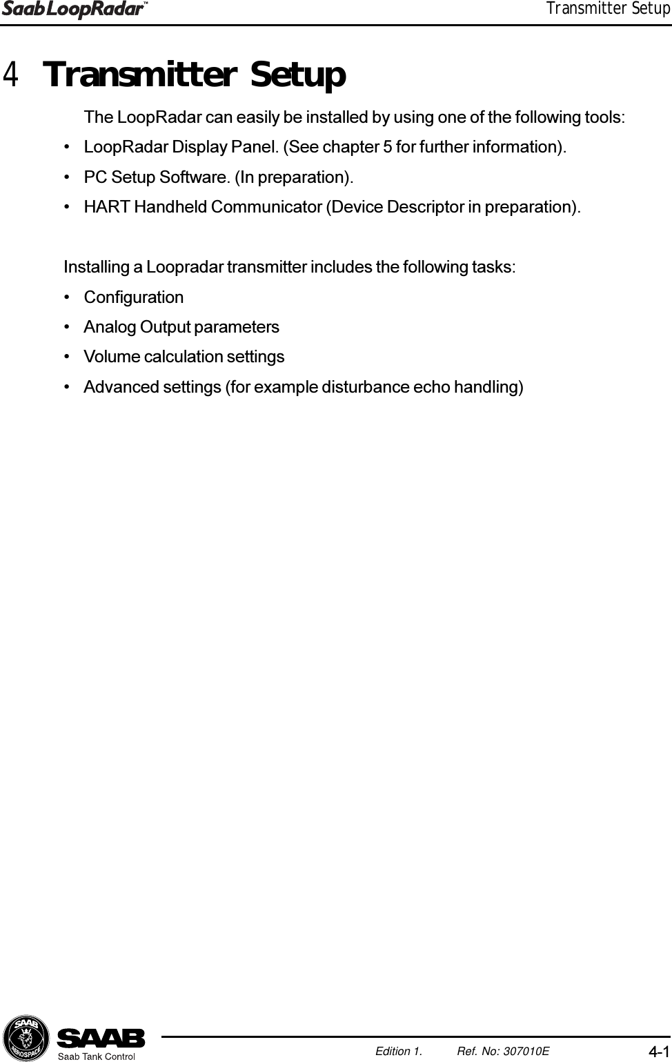
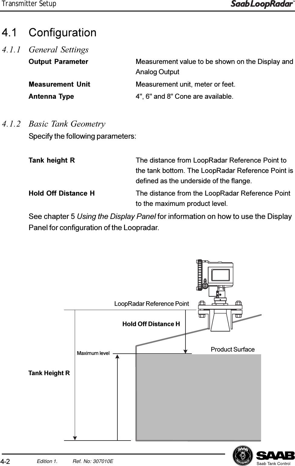
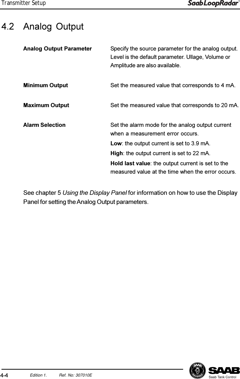
![5-6Edition 1. Ref. No: 307010EUsing the Display Panel5.4 ConfigurationOutput parameter1. Choose sub menu [1-1].2. Choose one of the following parameters to be displayed on the panel:0: Level, 1: Ullage, 2: Volume (%), 3: Current, 4: Amplitude.Antenna type1. Move to sub menu [1-2].2. Choose one of the following antennas:0: 4 inch Horn Antenna.1: 6 inch Horn Antenna.2: 8 inch Horn Antenna.Measurement Unit1. Choose sub menu [1-3].2. Choose one of the following options:0: meter.1: feet.Tank Distances1. Choose sub menu [1-5] and enter the tank height R. Measure R from theLoopRadar Reference Point to the tank bottom.2. If the Zero Level reference point is located above the tank bottom, choosesub menu [1-6]. (This may be the case if for example a Datum Plate isused).In order to be able to measure levels below the Zero Level, enter the Cdistance from the Zero Level to the tank bottom.If C is set to 0, levels below the zero reference point will be presented as 0.See chapter 4.1.2-3 for more information on the definition of tank geometry pa-rameters.Hold Off Distance1. Choose sub menu [1-7].2. Enter the Hold Off distance H. The Hold Off distance is defined as the dis-tance from the LoopRadar Reference Point to the upper limit of the Ap-proved Measurement Range.See chapter 4.1 for further information on the definition of tank geometry.](https://usermanual.wiki/Rosemount-Tank-Radar/LOOPRADAR/User-Guide-99369-Page-35.png)
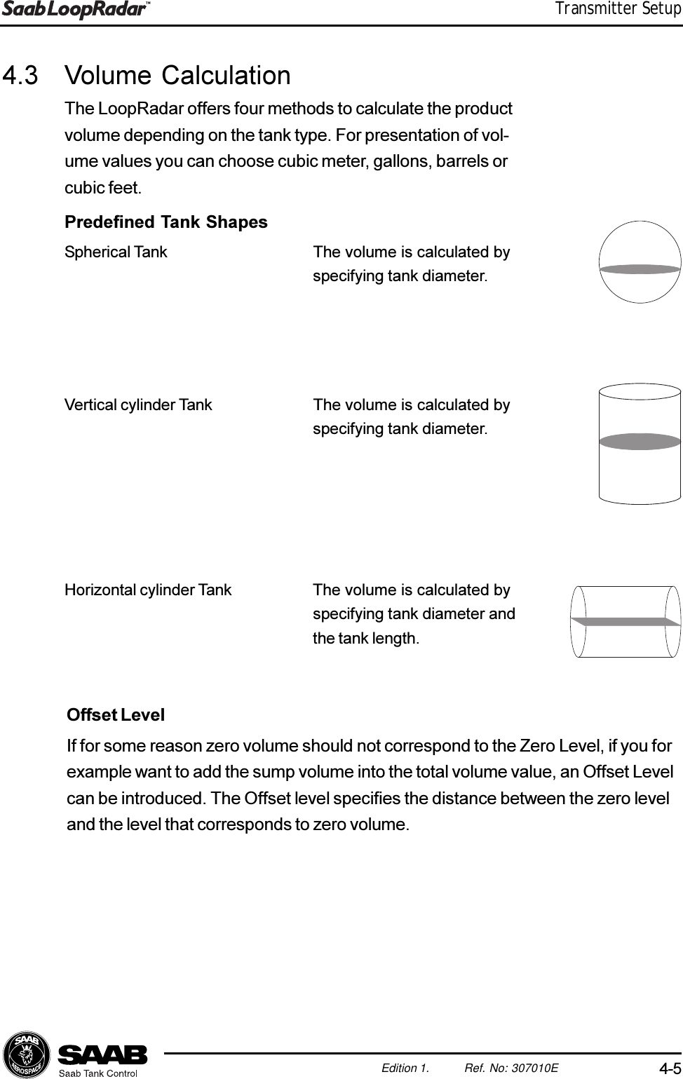
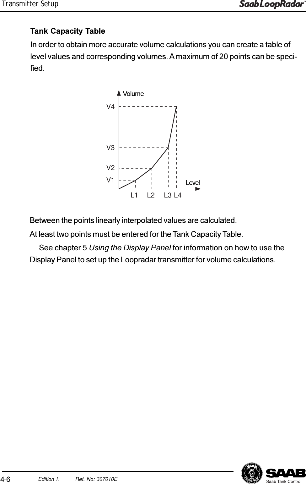
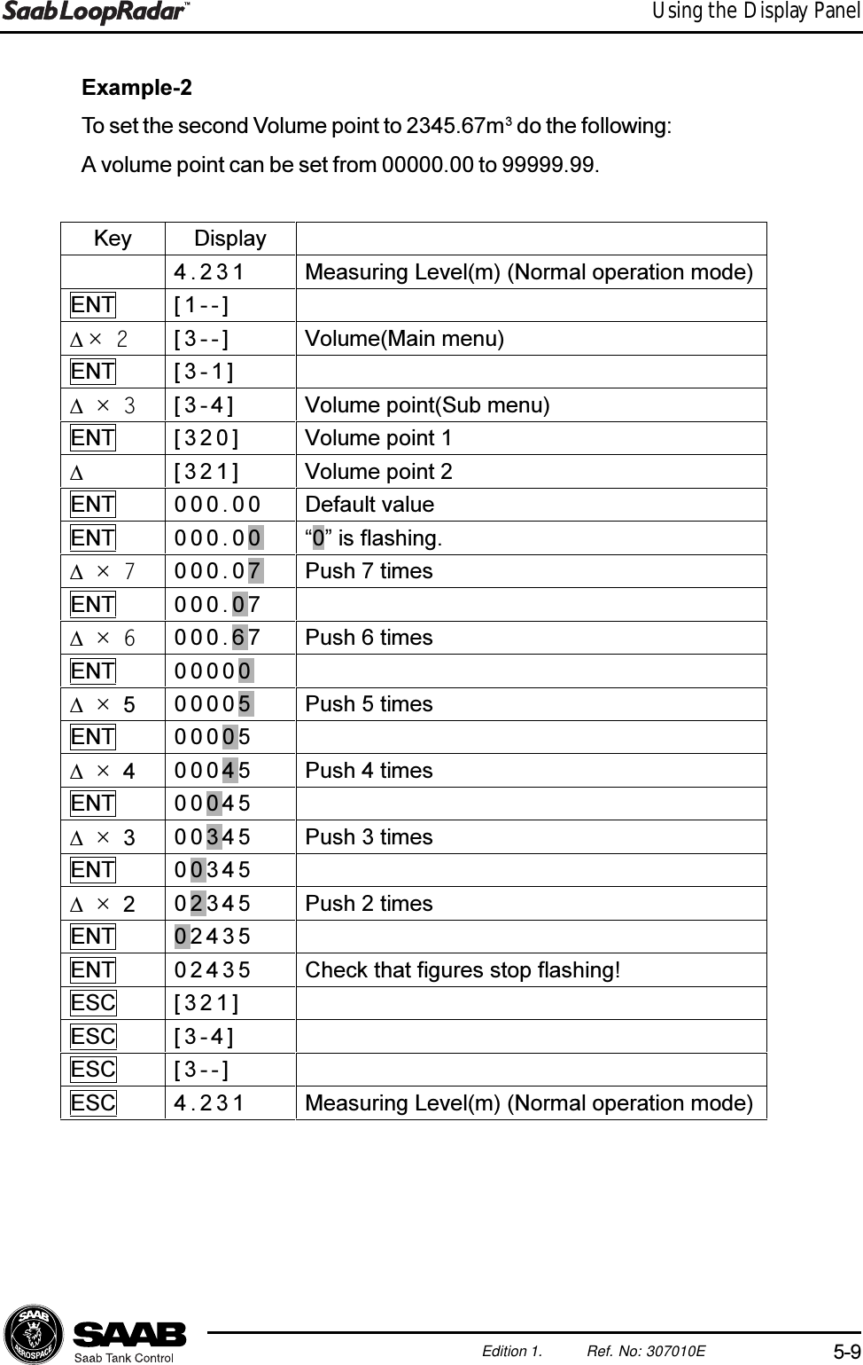
![5-8Edition 1. Ref. No: 307010EUsing the Display Panel5.5 Volume CalculationTank Type1. Choose sub menu [3-1] to specify calculation method.2. Choose one of the following options:0 No volume calulation is performed.1Volume calculation is based on the shape of a Vertical Cylinder.2Volume calculation is based on the shape of a Spherical tank.3 Volume calculation is based on the shape of a HorizontalCylinder.4Volume calculation is based on a table of level values and corre-sponding volumes. See section Tank Capacity Table for furtherinformation.Tank DimensionsDiameter Choose sub menu [3-6] to specify tank diameter forVertical Cylinder or Spherical tank.Length Choose sub menu [3-7] to specify length for Hori-zontal Cylinder tank.OffsetChoose sub menu [3-8] to specify a level offset if you do not want the volumeto be zero at the Zero Level reference point.Tank Capacity Table1. Choose sub menu [3-2] in order to specify the number of linearization pointsfor the Tank Capacity Table.2. Choose sub menu [3-3] and enter the level values. Enter as many points asspecified in sub menu [3-2].3. Choose sub menu [3-4] and enter the volumes that correspond to the levelvalues entered in sub menu [3-3].4. Choose sub menu [1-1] to choose volume as output parameter on the Dis-play Panel.5. Return to measurement mode.](https://usermanual.wiki/Rosemount-Tank-Radar/LOOPRADAR/User-Guide-99369-Page-37.png)
![5-10Edition 1. Ref. No: 307010EUsing the Display Panel5.6 Setting up the Analog OutputOutput parameter1. Choose sub menu [2-1].2. Choose one of the following parameters as source signal for the AnalogOutput:0: Level,1: Ullage,2: Volume (%),3: Amplitude.Output range1. Choose sub menu [2-2] to enter the Minimum Output value corresponding tothe Analog Output value 4 mA.2. Choose sub menu [2-3] to enter the Maximum Output value corresponding tothe Analog Output value 20 mA.Setting up the Alarm Mode1. Choose sub menu [2-4] to specify Alarm mode for the Analog Output.2. Choose one of the following options:0: High. The current is fixed at 22 mA when an alarm is activated.1: Low. The current is fixed at 3.9 mA when an alarm is activated.2: Hold Last Value. The analog output current is fixed at the present value.](https://usermanual.wiki/Rosemount-Tank-Radar/LOOPRADAR/User-Guide-99369-Page-39.png)
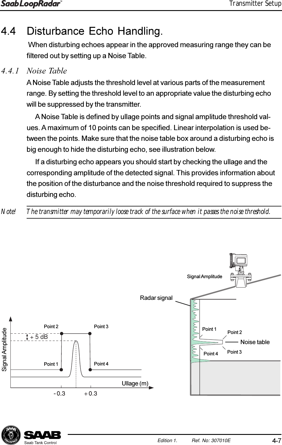
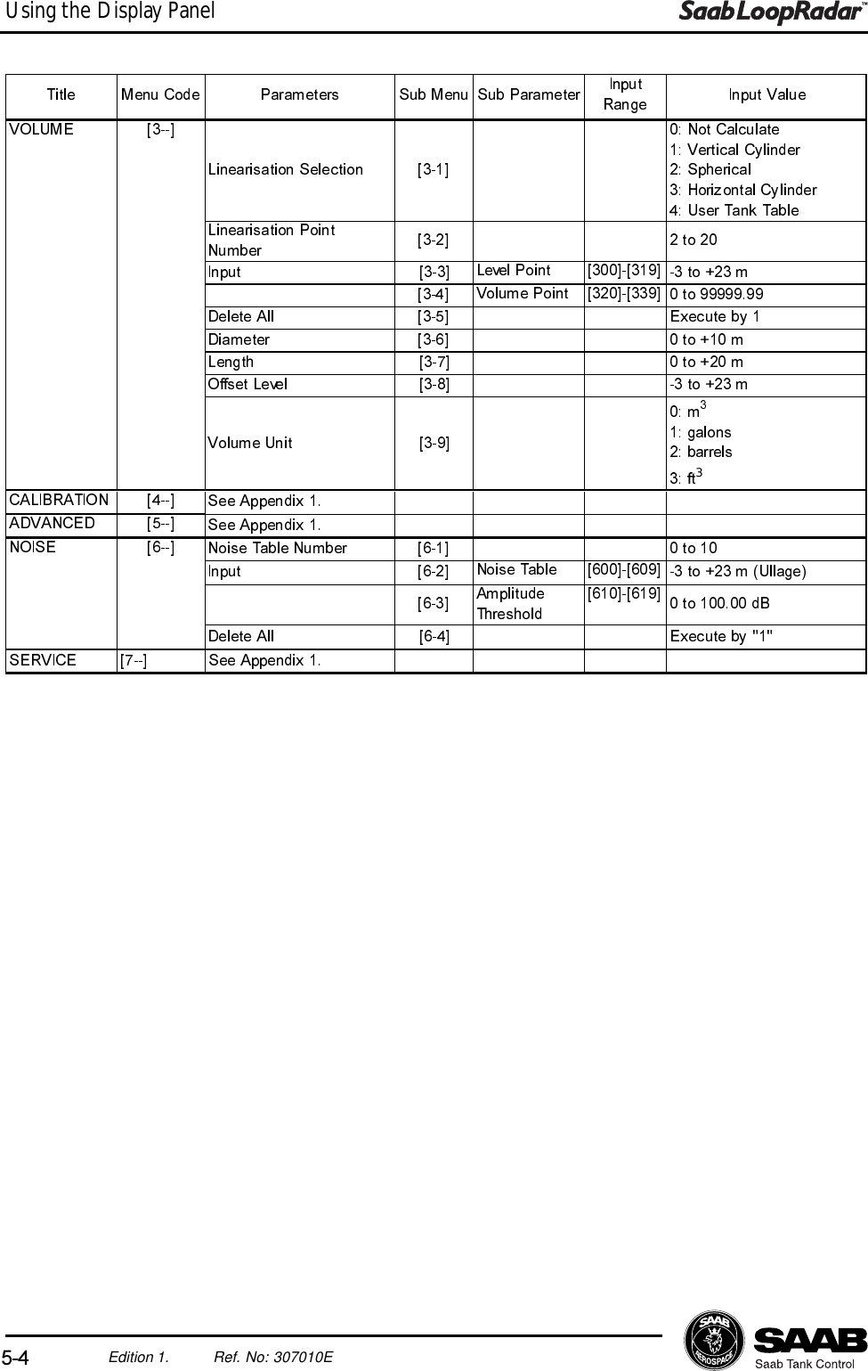
![5-11Edition 1. Ref. No: 307010EUsing the Display Panel5.7 Disturbance Echo Handling5.7.1 Setting up a Noise Threshold TableIf the transmitter has locked to a disturbing echo you can create a Noise ThresholdTable in order to suppress the disturbing echo:1. Do the following to check where the disturbing echo is located and the corre-sponding radar signal amplitude:1. Choose sub menu [1-1] and set the Output Parameter to Ullage.2. Note the Ullage value.3. Choose sub menu [1-1] and set the Output Parameter to Amplitude.4. Note the Amplitude value.5. Choose sub menu [1-1] and set the Output Parameter to the desiredvalue (see the Key Parameter list).Now you can start creating the noise table.2. Choose sub menu [6-1].3. Specify the number of points you want to use for the Noise Threshold Table.In order to suppress a single peak signal four points is sufficient. For morecomplicated noise tables you can use up to ten points.4. Choose sub menu [6-2] and enter the ullage values that correspond to thedesired noise table break points. The points must be added in consecutiveorder. Use a margin of ± 0.3 meter, see illustration below.5. Choose sub menu [6-3] and enter the amplitude threshold values that corre-spond to the desired noise table break points. A margin of + 5 dB is suffi-cient in most cases.+ 5 dBSignal AmplitudeUllagePoint 1Point 2 Point 3Point 46. Return to measuring mode and check that the transmitter detects the productsurface.](https://usermanual.wiki/Rosemount-Tank-Radar/LOOPRADAR/User-Guide-99369-Page-40.png)
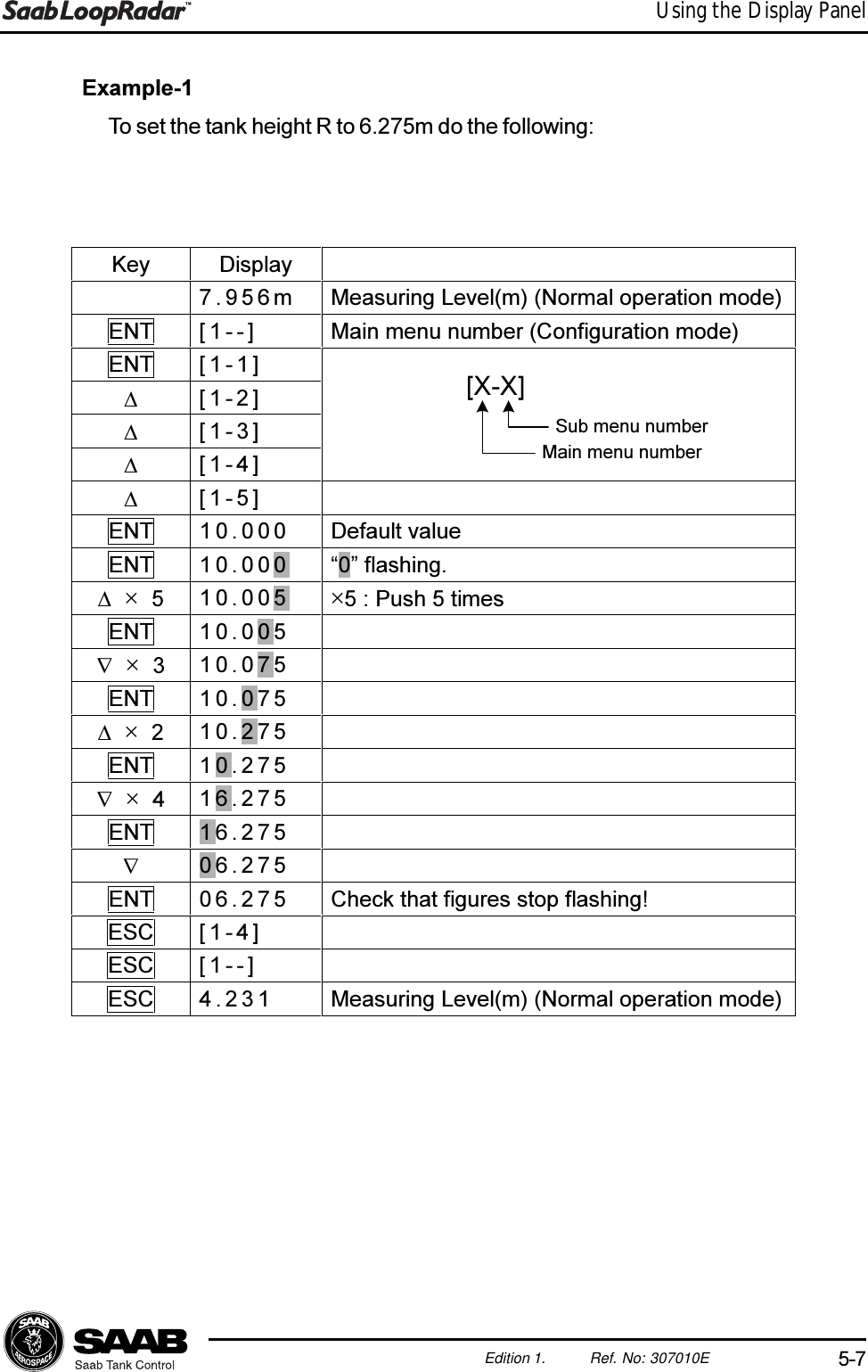
![5-12Edition 1. Ref. No: 307010EUsing the Display PanelExample.A disturbing echo is located at Ullage=3 m. The signal amplitude of the disturbingecho is 3 dB. The following Noise Theshold Table is created to suppress thisecho:Sub menu [6-1]: 4 (4 points in the noise table).Sub menu [6-2]:Point 1: [600]=2.7.Point 2: [601]=2.7.Point 3: [602]=3.3.Point 4: [603]=3.3.Sub menu [6-3]:Point 1: [610]=0 dB.Point 2: [611]=8 dB.Point 3: [612]=8 dB.Point 4: [613]=0 dB.3 dB0 dB8 dB2.7 3 3.3Point 1Point 2 Point 3Point 4UllageSignal Amplitude](https://usermanual.wiki/Rosemount-Tank-Radar/LOOPRADAR/User-Guide-99369-Page-41.png)

![7-1Edition 1. Ref. No: 307010ETroubleshooting7 TroubleshootingLCD status messages[E--] Normal Operation[E01] Internal Error. Serious error. Please contact servicedepartment.[E02] Memory Error. Serious error. Please contact servicedepartment.[E03] Receive Error. No measure data. Please contact service[E04] Tank CapacityTable Error. Incorrect setting of Tank Capacity Table.[E05] Noise Table Error. Incorrect setting of noise table.[E99] Searching. Searching for Echo](https://usermanual.wiki/Rosemount-Tank-Radar/LOOPRADAR/User-Guide-99369-Page-46.png)
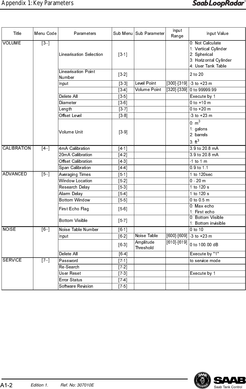
![A1-1Edition 1. Ref. No: 307010EAppendix 1: Key ParametersAppendix 1: Key ParametersBy using the Display Panel keys you can make a complete configuration of theLoopRadar. The various settings are grouped into seven main menus:[1--] Configuration Basic configuration of tank dimensions, antennatype and output parameter.[2--] Analog Configuration of analog output signal.[3--] Volume Specification of method for volume calculations.[4--] Calibration Calibration of analog output range and calibration oflevel measurements.[5--] Advanced Advanced configuration for improving measurementperformance in difficult environments.[6--] Noise Option to create a noise table in order to suppressdistinct disturbing echoes.[7--] Service Special functions for service actions.$QWHQQD7\SH >@LQFK+RUQ$QWHQQDLQFK+RUQ$QWHQQDLQFK+RUQ$QWHQQD0HDV8QLW >@ PHWHUIHHW* >@ WRP5&* P5 >@ WRP5&* P& >@ WRP5&* P+ >@ WRP$QDORJ2XWSXW3DUDPHWHU >@/HYHO8OODJH9ROXPH$PSOLWXGH0LQLPXP2XWSXW >@ WRP0D[LPXP2XWSXW >@ WRP$ODUP6HOHFWLRQ >@+LJKP$/RZP$+ROGODVWYDOXH)L[HG&XUUHQW2XWSXW >@ WRP$)L[HGZKHQP$&21),*85$7,21 >@>@$1$/2*7LWOH 0HQX&RGH ,QSXW9DOXH2XWSXW3DUDPHWHU >@/HYHO8OODJH9ROXPH&XUUHQW$PSOLWXGH3DUDPHWHU 6XE0HQX 6XE3DUDPHWHU ,QSXW](https://usermanual.wiki/Rosemount-Tank-Radar/LOOPRADAR/User-Guide-99369-Page-50.png)