Rosemount Tank Radar LOOPRADAR Radar Level Gauge User Manual Cover LoopRadar
Rosemount Tank Radar AB Radar Level Gauge Cover LoopRadar
Preliminary users manual
User´s Guide
Preliminary edition

(i)
User´s Guide
First edition
Edition 1. Ref. No: 307010E
Copyright © April 2000
Saab Marine Electronics AB

(ii)
Edition 1. Ref. No: 307010E
Copyright © April 2000
Saab Marine Electronics AB
The contents, descriptions and specifications within this manual is subject to
change without notice. Saab Marine Electronics AB accepts no responsibility for
any errors that may appear in this manual.
Trademarks
HART is a registered trademark of HART Communication Foundation.
LoopRadar is a trademark of Saab Marine Electronics AB.
TankRadar is a registered trademark of Saab Marine Electronics AB.
Spare Parts
Any substitution of non-recognized spare parts may jeopardize safety. Repair, e.g.
substitution of components etc., may also jeopardize safety and is under no cir-
cumstances allowed.
Saab Tank Control will not take any responsibility for faults, accidents, etc. caused
by non-recognized spare parts or any repair which is not made by
Saab Tank Control.
Safety
This manual applies to equipment covered by certificate number
SIRA 00ATEX2052X.
The equipment may be used with flammable gases and vapours with apparatus
groups IIA, IIB and IIC and with temperature classes T1 to T4 inclusive.
The equipment is only certified for use in ambient temperatures in the range
-40 °C to +70 °C and should not be used outside this range.
The Saab LoopRadar transmitter must be installed by suitably trained personnel
according to the instructions in this manual and in accordance with the applicable
code of practice. The certificate number has an ’X’ suffix which indicates that
special conditions for cable capacitance apply. For specification of cable capacitance
see the certificate.
Repair of this equipment shall be carried out in accordance with the applicable code
of practice.
( iii )
Edition 1. Ref. No: 307010E
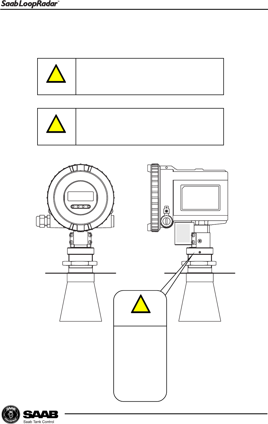
The various warning messages shown in the Users Guide are indicated as follows:
Indicates that incorrect usage may result in
personal injury or malfunctioning instruments.
!
Caution
Indicates a potentially hazardous situation
which could result, if not avoided, in death
or serious injury.
!
Warning
!
Warning
Don´t open
lower nut
if tank is
pressurised
or contains
hazardous
product.

(iv)
Edition 1. Ref. No: 307010E
Contents
About this manual....................................................... vi
1 Product Description ...................................... 1-1
1.1 Features ................................................................................ 1-1
1.2 Measurement Principle.......................................................... 1-2
2 Mechanical Installation ................................. 2-1
2.1 Requirements ........................................................................ 2-1
2.2 Dimensions ........................................................................... 2-3
2.3 Tools ...................................................................................... 2-4
2.4 Mounting the Cone Antenna .................................................. 2-5
2.5 Installation Hints..................................................................... 2-7
3 Electrical Installation..................................... 3-1
3.1 Connecting the LoopRadar ................................................... 3-1
3.2 Cables ................................................................................... 3-3
3.3 Load ...................................................................................... 3-3
3.4 Power supply ......................................................................... 3-3
3.5 Grounding .............................................................................. 3-3
4 Transmitter Setup .......................................... 4-1
4.1 Configuration ......................................................................... 4-2
4.1.1 General Settings ........................................................ 4-2
4.1.2 Basic Tank Geometry ................................................ 4-2
4.1.3 Advanced Tank Geometry ........................................ 4-3
4.2 Analog Output........................................................................ 4-4

(v)
Edition 1. Ref. No: 307010E
4.3 Volume Calculation ................................................................ 4-5
4.4 Disturbance Echo Handling. .................................................. 4-7
4.4.1 Noise Table ................................................................ 4-7
5 Using the Display Panel ................................ 5-1
5.1 Display Panel......................................................................... 5-1
5.1.1 Display ....................................................................... 5-1
5.1.2 Keys ........................................................................... 5-2
5.2 Basic Key Parameter List ...................................................... 5-3
5.3 Navigating the Display Panel Menus ..................................... 5-5
5.4 Configuration ......................................................................... 5-6
5.5 Volume Calculation ................................................................ 5-8
5.6 Setting up the Analog Output............................................... 5-10
5.7 Disturbance Echo Handling ................................................. 5-11
5.7.1 Setting up a Noise Threshold Table ....................... 5-11
6 Technical Information ................................... 6-1
7 Troubleshooting ............................................ 7-1
Index ............................................................................... I
Appendix 1: Key Parameters ................................. A1-1

(vi)
Edition 1. Ref. No: 307010E
About this manual
The main purpose of Users Guide is to act as guide to installing and operating
the Saab LoopRadar. It is not intended to cover service tasks such as changing
circuit boards or internal software.
Chapter 1 reviews some basic concepts of radar based level gauging.
Chapter 2 describes how to assemble a gauge and how to mount it on a tank.
Chapter 3 describes the electrical installation.
Chapter 4 describes the parameters that need to be configured, how to handle
disturbing echoes and various options for volume calculation.
Chapter 5 describes how to use the Display Panel to configure the Saab Loopradar.
Chapter 6 provides technical information.
Chapter 7 lists the various error codes that may appear.
1-1
Edition 1. Ref. No: 307010E
Product Description
1 Product Description
The LoopRadar transmitter uses a non-contact level gauging measurement tech-
nique based on the principle of pulsed microwaves. It is loop-powered and easy
to install and can be used for many types of level measurement applications. The
LoopRadar is safe for humans and has no environmental impact. Propagation of
microwaves is virtually unaffected by temperature, pressure or gas characteristics
in the tank resulting in excellent measurement stability.
1.1 Features
Loop-Power
The LoopRadar only needs one two-wire line for both power supply and output
signal. The LoopRadar is powered by a PLC or a power supply unit.
Communication
The LoopRadar has a 4-20 mA current output and a HART protocol interface for
digital data transmission. The transmitter can be configured by using a HART
communicator (Device Descriptor in preparation), a PC-based setup software or
the Display Panel.
LoopRadar with
analog output signal
4-20 mA and HART
interface.
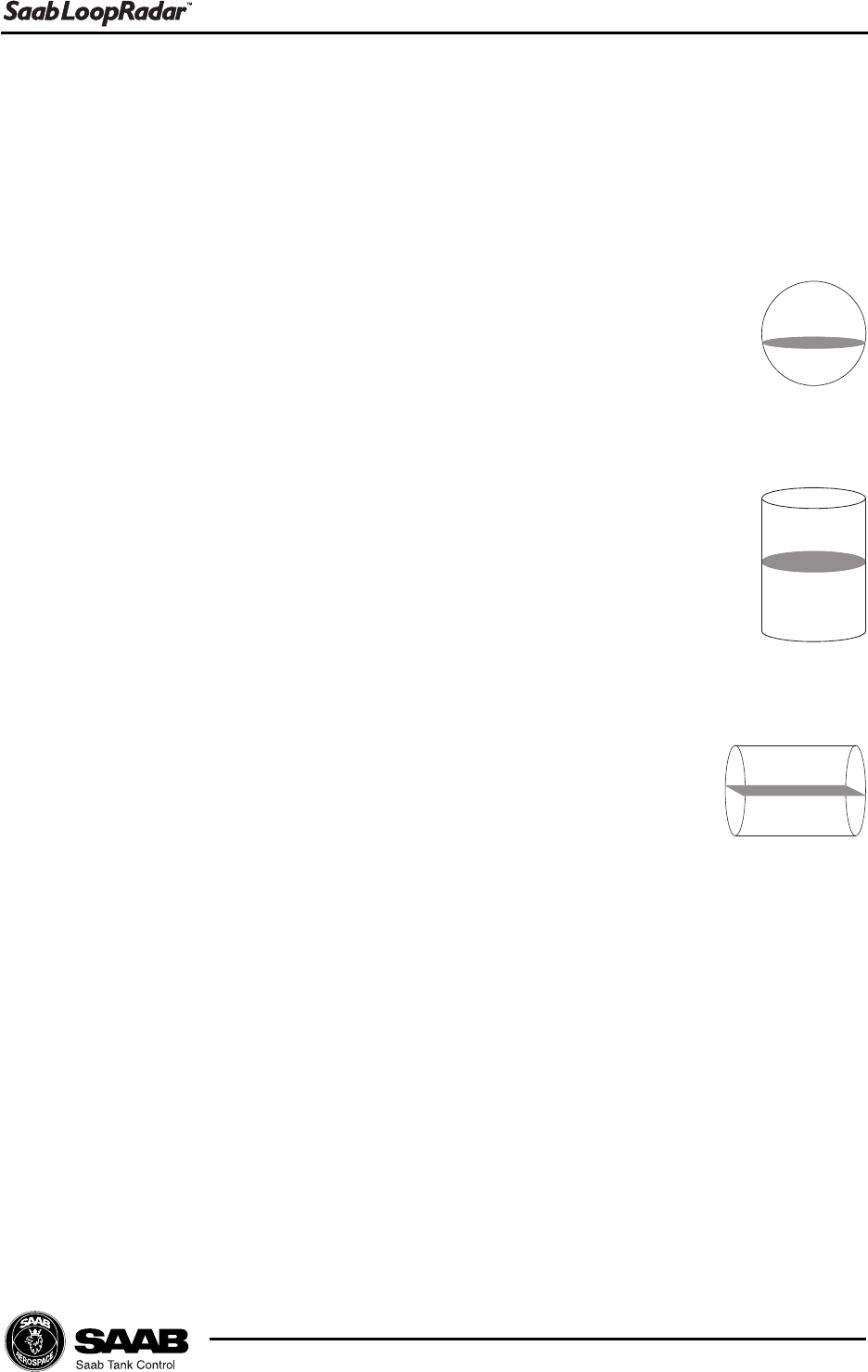
Volume calculation function
A calculation function transforms the measured level into the corresponding prod-
uct volume. The volume calculation is based on one of the standard tank shapes
Sphere, Vertical cylinder or Horizontal cylinder. The LoopRadar also offers the
possibility to calculate the product volume for an arbitrary tank shape by specifying
a Tank Capacity Table consisting of up to 20 levels and corresponding volumes.
1-2
Edition 1. Ref. No: 307010E
Product Description
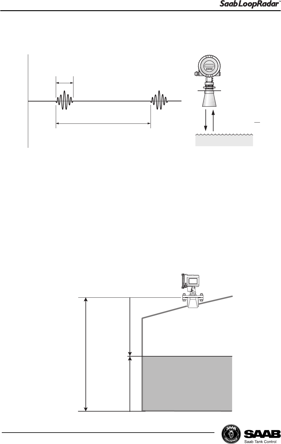
1.2 Measurement Principle
Ullage
Level
1 ns
1 µs
Pulse sequence
Distance=c* 2
t
A LoopRadar gauge is installed at the tank top. It emits short microwave pulses
towards the product surface in the tank. The emitted microwaves hit the product
surface and are reflected back to the antenna for subsequent processing by the
transmitter electronics. The time from transmission to reception (t) is detected by
a micro-processor and is converted to the distance between the transmitter and
the product surface. The measured distance is often referred to as the Ullage.
The product level is calculated by using the following relation between tank height
and Ullage:
Level=Tank Height - Ullage.
Tank Height
2-1
Edition 1. Ref. No: 307010E
Mechanical Installation
2 Mechanical Installation
2.1 Requirements
Mounting position
Do not mount the transmitter at the center of the tank or close to the tank wall.
This may reduce the measuring range or the accuracy and makes the transmitter
more sensitive to disturbing echoes. We recommend that the transmitter is
mounted so that the antenna tip is located at least 0.5 m from the tank wall.
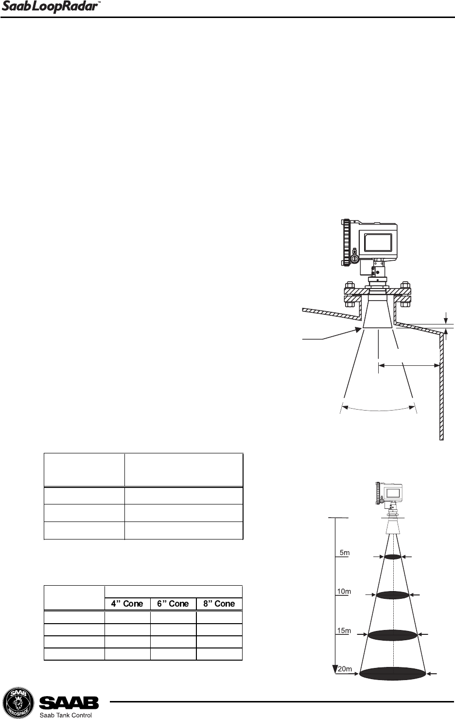
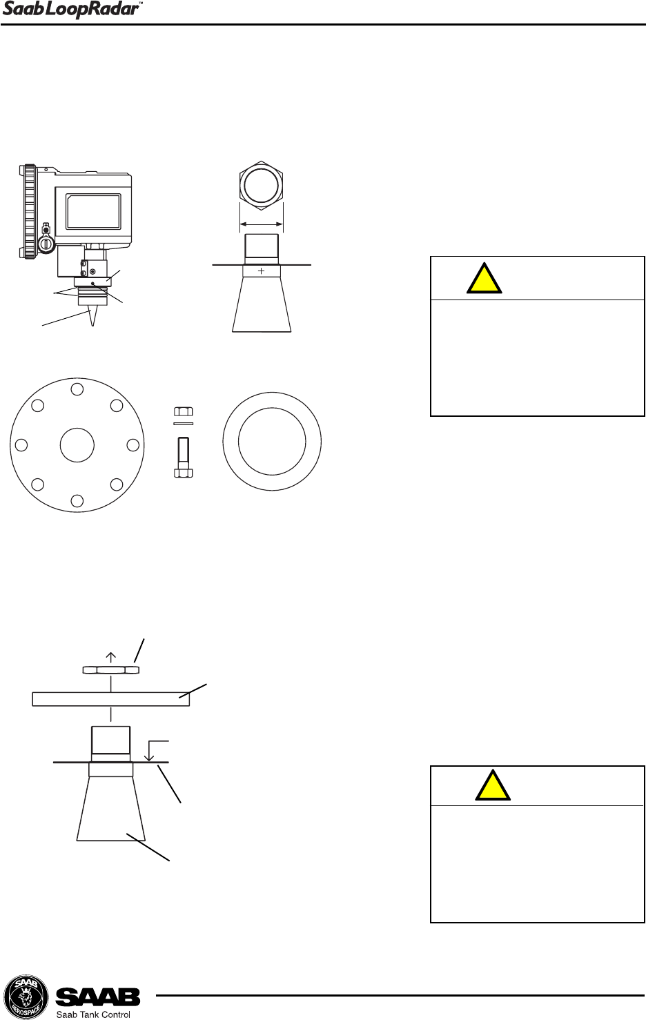
Socket requirements
The antenna tip should be located outside the
nozzle (10 mm or more ).
If the antenna is located inside the nozzle
the antenna tip may cause disturbing echoes
which will negatively affect measurement
performance.
Free space requirements
The transmitter should be mounted so that no
obstacles are present in the radar beam.
Obstacles in the radar beam may reduce the
measuring range.
Distance
Diameter of radiated area (m).
$QWHQQD7\SH
'LVWDQFHP
$QWHQQD7\SH
&RQH
&RQH
&RQH
+DOI3RZHU%HDP:LGWK
'HJUHHV
Half Power Beam Width.
Antenna
tip
10 mm
or more
500 mm or more
Half Power Band Width
2-2
Edition 1. Ref. No: 307010E
Mechanical Installation
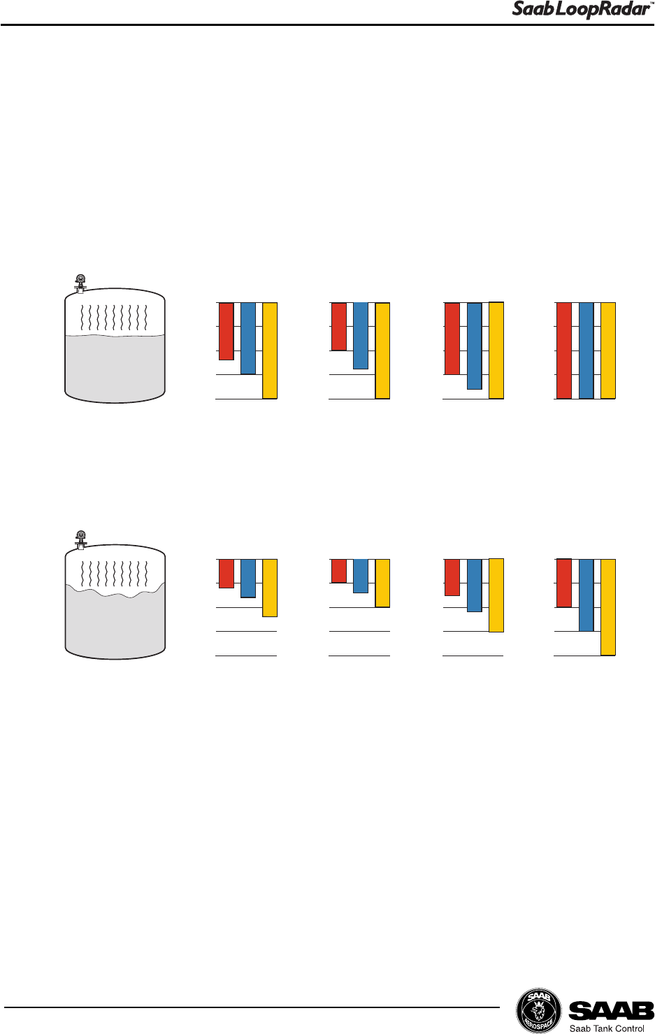
Maximum measuring distance
Maximum measurement distance is determined by antenna type, dielectric con-
stant of the product and product surface conditions. Please refer to the table
below. These values are rough estimates, and are strongly influenced by the
measuring conditions.
a) Dielectric constant 1.9 - 4.0 Oil, gasoline and other hydrocarbons,
petrochemicals
b) Dielectric constant 4.0 - 10 Alcohols, concentrated acids, organic
solvents
c) Dielectric constant > 10 Water based liquids, dilute acids, acetone
4" Cone 6" Cone 8" Cone
0
10
20
0
10
20
0
10
20
0
10
20
abc abc abc
(m)
Rod
abc
4" Cone 6" Cone 8" Cone
0
10
20
0
10
20
0
10
20
0
10
20
abc abc abc
(m)
Rod
abc
Calm surface
Turbulent surface
2-3
Edition 1. Ref. No: 307010E
Mechanical Installation
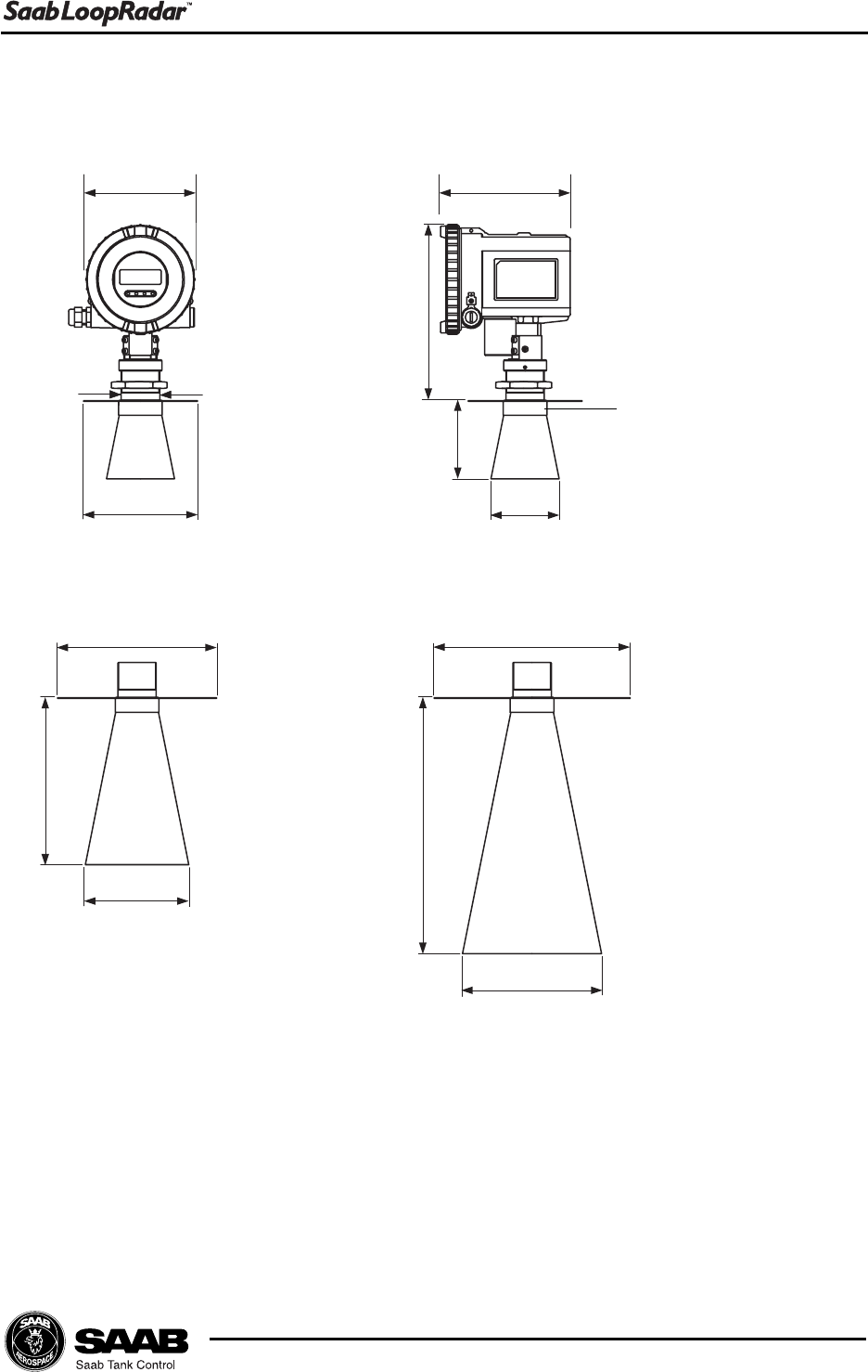
2.2 Dimensions
Weight
LoopRadar(except antenna) 2.5 kg
4 Cone antenna 0.8 kg
6 Cone antenna 1.2 kg
8 Cone antenna 1.8 kg
148 mm 172 mm
Ø 52 mm
Ø 154 mm
238 mm
106 mm
226 mm
346 mm
Ø 92 mm
Ø 140 mm
Ø 188 mm
8 Cone antenna
6 Cone antenna
4 Cone antenna
Ø 265 mm
Ø 215 mm
Ø 59 mm
2-4
Edition 1. Ref. No: 307010E
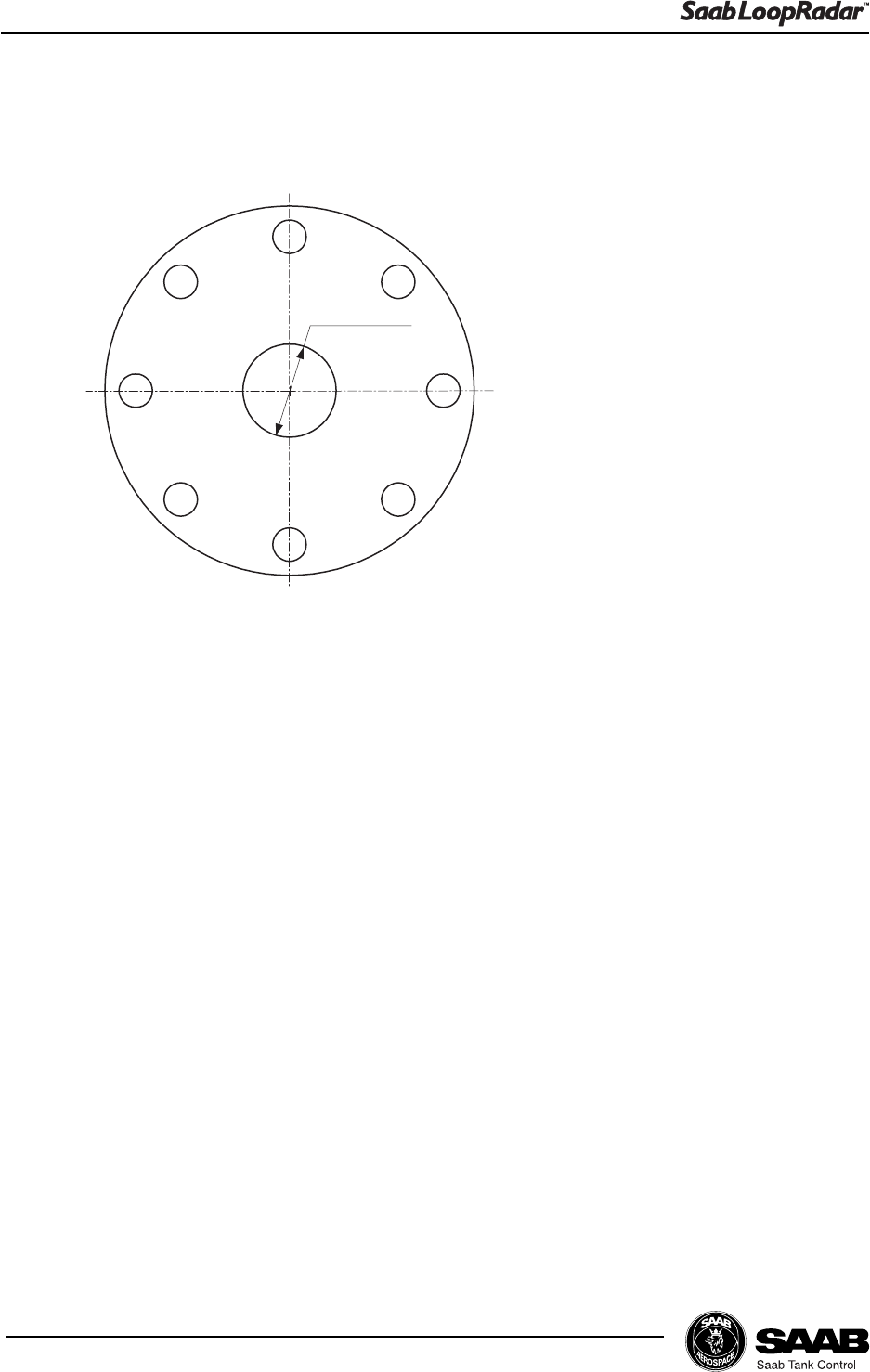
Mechanical Installation
Flange
The LoopRadar gauge is mounted by using a flange according to the following
specifications:
Maximum thickness : 29mm (ANSI Class-150 8 ).
2.3 Tools
The following tools are needed for installation of LoopRadar:
Hexagon socket screw keys(-4)
Adjustable wrench (for locking nut)
Pipe wrench (for neck of cone antenna)
Screw driver (-) width 3mm
Ø 54 mm
2-5
Edition 1. Ref. No: 307010E
Mechanical Installation
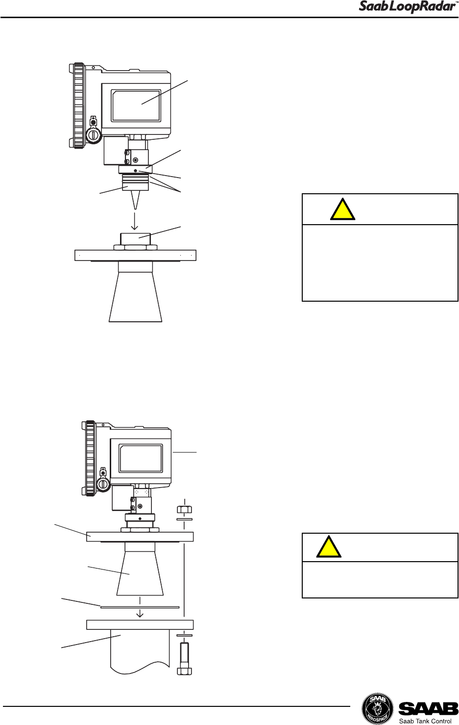
2.4 Mounting the Cone Antenna
1Make sure that the following
parts are available when
installing the gauge.
2Mount the flange on top of the
cone plate.
Secure the flange with the
locking nut and make sure
that the nut is fitted tightly to
the flange.
Make sure that the PTFE Seal
and the O-rings are not dam-
aged. Damaged PTFE Seal or
O-ring may cause gas leakage
from pressurized tanks.
!
Caution
Make sure that the bottom
side of the flange is flat and
all parts are clean and dry in
order to avoid gas leakage
from pressurized tanks.
!
Caution
Transmitter Locking nut
Flange Gasket
Nuts and bolts
Union nut
Set screw
O-ring
Seal
Locking nut
Flange
Note!
No gasket here.
Cone plate
Cone antenna
2-6
Edition 1. Ref. No: 307010E
Mechanical Installation
3Carefully insert the transmitter
antenna adapter into the
sleeve and make sure that it
fits well into the cone antenna.
Secure the antenna adapter
with the union nut.
Secure the union nut with the
set screw.
4Place the gasket on the tank
nozzle.
Carefully fit the transmitter
with flange and cone antenna
on the tank nozzle.
Tighten the screws and nuts.
Make sure that the O-ring and
the inside of the sleeve are
clean in order to avoid gas
leakage when using LoopRadar
in pressurized tanks.
!
Caution
Do not loosen union nut when
the tank is pressurized.
!
Warning
Gasket
Tank nozzle
Transmitter
Flange
Cone antenna
Transmitter
Union nut
Set screw
O-rings
Sleeve
Antenna
adapter
2-7
Edition 1. Ref. No: 307010E
Mechanical Installation
2.5 Installation Hints
If obstacles are present in the radar beam, the signal reflected from the product
surface may be weaker than the signal from the disturbing object. In this case the
LoopRadar may lock on the disturbing object instead of the liquid surface. To
reduce the influence of the disturbing object use the following method:
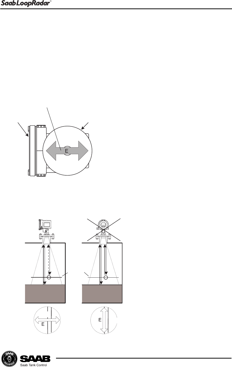
Thin pipes
Reflections of microwaves from
elongated metal like thin pipes
are strongest when the axis and
electric field are parallel. The
direction of the electric field is
shown in the figure to the right.
Mount the LoopRadar in a direc-
tion where the electric field and
the obstacle are not parallel. That
way the false echo from the ob-
stacle will have less influence on
the measurement performance.
Front Cover Cone antenna
Electric Field
Correct
A-plane
Pipe
A-plane
top view
Pipe
Wrong
Pipe
2-8
Edition 1. Ref. No: 307010E
Mechanical Installation
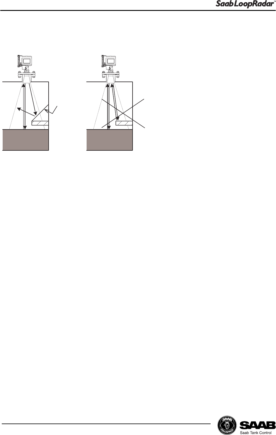
Shoulders and Struts
Flat surfaces may cause strong
false echoes. In order to reduce
the impact of such false echoes
you can mount a metal plate above
the obstacle as shown in the figure.
Correct Wrong
Reflector
Shoulder
3-1
Edition 1. Ref. No: 307010E
Electrical Installation
3 Electrical Installation
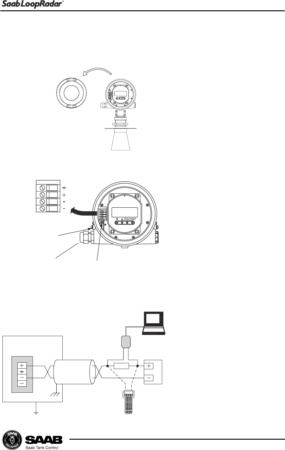
3.1 Connecting the LoopRadar
1Remove the front cover.
3Connect the shield to the
ground terminal.
4Tighten the front cover.
Please handle it carefully
so that the gasket and
window are not removed.
Make sure that the cover
is fully tightened so that
the housing is properly
sealed by the gasket.
Housing
Terminal block
HART
modem
Power
supply
Hand-held communicator
250 W
2Connect the cable to the
terminal block trough the
cable entry.
Ground terminal
Ground terminal
Terminal block
Cable entry
3-2
Edition 1. Ref. No: 307010E
Electrical Installation
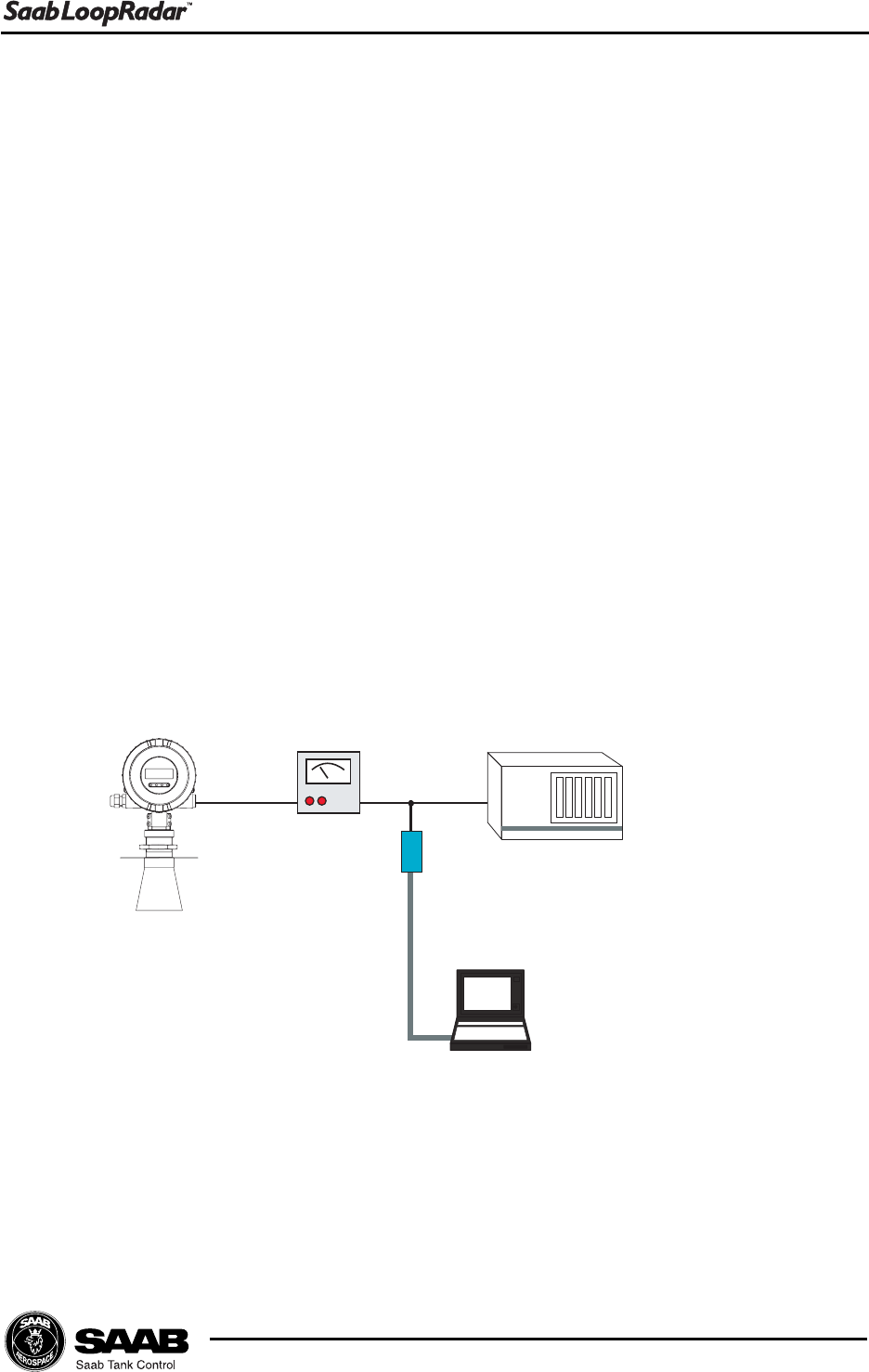
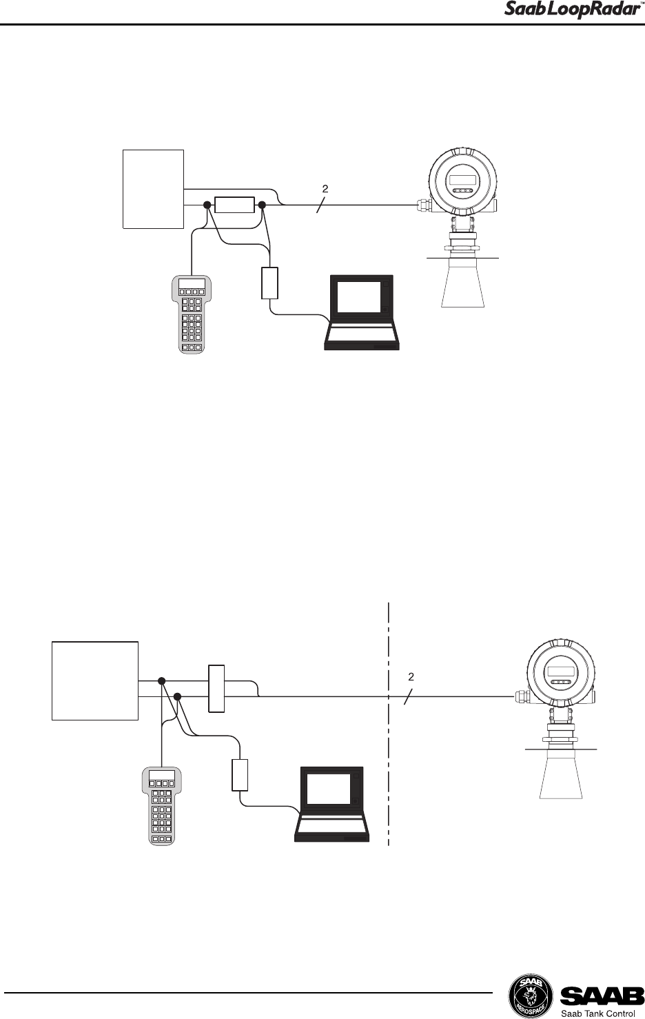
Example-1 Connection to power supply unit. LoopRadar mounted in non-hazardous
area.
Example-2 Connection to PLC etc. LoopRadar mounted in hazardous area.
Power
supply
> 250 W4 - 20 mA
HART
modem
Hand-held HART
communicator
LoopRadar
Analog instru-
ment or DCS
system (Active)
Isolator
HART
modem
Non-hazardous area Hazardous area
4 - 20 mA
LoopRadar
Hand-held HART
communicator

3-3
Edition 1. Ref. No: 307010E
Electrical Installation
3.2 Cables
Cable Use shielded twisted pair for connection.
Cable entry 2 x M20 x 1.5, NPT 1/2 " (cable diameter 5-9 mm)
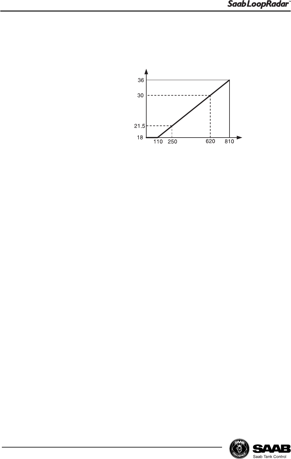
3.3 Load
Minimum load for HART 250 W
Maximum load (Non-Ex) 810 W
Maximum load (Ex) 620 W
3.4 Power supply
Supply voltage (Non-Ex) 1836 VDC
Supply voltage (EX) 1830 VDC
IS parameters Ui=30 V, Ii=110 mA, Pi=825 mW, Li=0,
Ci=see certificate
3.5 Grounding
The terminal must be connected to ground before it is connected to other equip-
ment.

3-4
Edition 1. Ref. No: 307010E
Electrical Installation

4-1
Edition 1. Ref. No: 307010E
Transmitter Setup
4Transmitter Setup
The LoopRadar can easily be installed by using one of the following tools:
LoopRadar Display Panel. (See chapter 5 for further information).
PC Setup Software. (In preparation).
HART Handheld Communicator (Device Descriptor in preparation).
Installing a Loopradar transmitter includes the following tasks:
Configuration
Analog Output parameters
Volume calculation settings
Advanced settings (for example disturbance echo handling)
4-2
Edition 1. Ref. No: 307010E
Transmitter Setup
4.1 Configuration
4.1.1 General Settings
Output Parameter Measurement value to be shown on the Display and
Analog Output
Measurement Unit Measurement unit, meter or feet.
Antenna Type 4", 6" and 8" Cone are available.
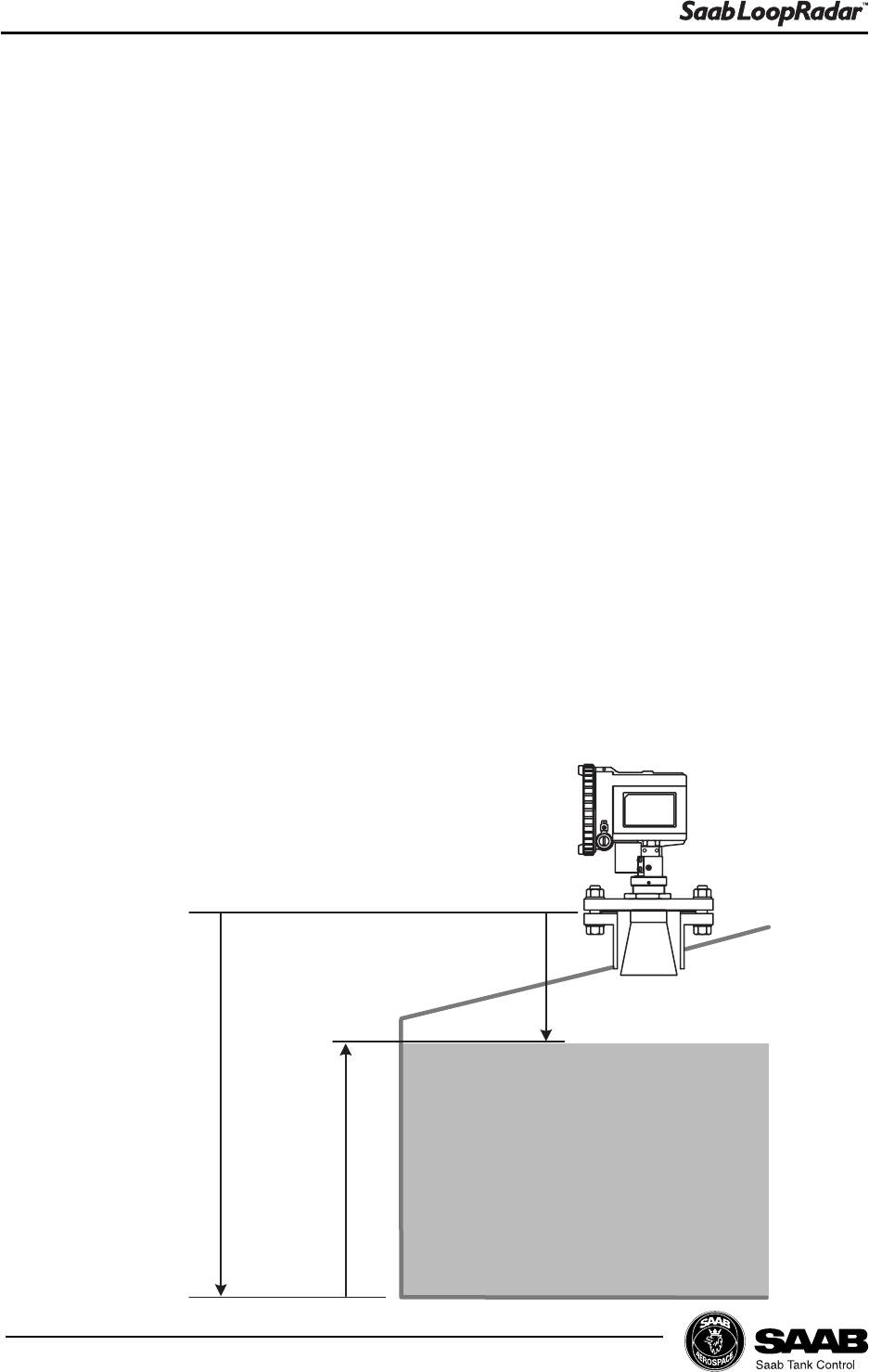
Maximum level
LoopRadar Reference Point
Hold Off Distance H
Product Surface
Tank Height R
4.1.2 Basic Tank Geometry
Specify the following parameters:
Tank height R The distance from LoopRadar Reference Point to
the tank bottom. The LoopRadar Reference Point is
defined as the underside of the flange.
Hold Off Distance H The distance from the LoopRadar Reference Point
to the maximum product level.
See chapter 5 Using the Display Panel for information on how to use the Display
Panel for configuration of the Loopradar.
4-3
Edition 1. Ref. No: 307010E
Transmitter Setup
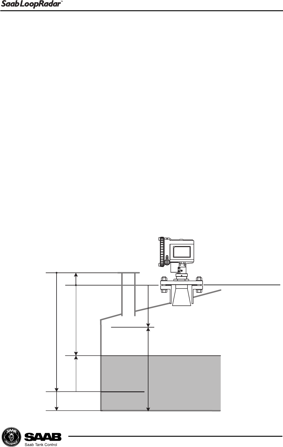
4.1.3 Advanced Tank Geometry
Min. Level Offset C The C distance is used to extend the measurement
range beyond the Zero Level Reference Point down
to the tank bottom. C is defined as the distance
between the Zero Level and the tank bottom. Set
C=0 if you do not want to present negative levels
below the Zero Level reference point, or if you use
the tank bottom as zero level reference point.
Reference Distance G In most cases the LoopRadar Reference Point is
used as the upper reference point. However, the
LoopRadar gauge offers the option to use a nozzle
for hand dipping as the upper reference point.
G is the distance between the LoopRadar Refer-
ence Point and the Tank Ullage Reference Point.
The LoopRadar Reference Point is located at the
underside of the flange.
Tank height R The distance from the Tank Ullage Reference Point
to the Zero Level.
Level
LoopRadar Reference Point
H
Measuring Range
Product Surface
Ullage
C
R
Zero Level
Tank Ullage Reference Point
G

4-4
Edition 1. Ref. No: 307010E
Transmitter Setup
4.2 Analog Output
Analog Output Parameter Specify the source parameter for the analog output.
Level is the default parameter. Ullage, Volume or
Amplitude are also available.
Minimum Output Set the measured value that corresponds to 4 mA.
Maximum Output Set the measured value that corresponds to 20 mA.
Alarm Selection Set the alarm mode for the analog output current
when a measurement error occurs.
Low: the output current is set to 3.9 mA.
High: the output current is set to 22 mA.
Hold last value: the output current is set to the
measured value at the time when the error occurs.
See chapter 5 Using the Display Panel for information on how to use the Display
Panel for setting the Analog Output parameters.
4-5
Edition 1. Ref. No: 307010E
Transmitter Setup
4.3 Volume Calculation
The LoopRadar offers four methods to calculate the product
volume depending on the tank type. For presentation of vol-
ume values you can choose cubic meter, gallons, barrels or
cubic feet.
Predefined Tank Shapes
Spherical Tank The volume is calculated by
specifying tank diameter.
Vertical cylinder Tank The volume is calculated by
specifying tank diameter.
Horizontal cylinder Tank The volume is calculated by
specifying tank diameter and
the tank length.
Offset Level
If for some reason zero volume should not correspond to the Zero Level, if you for
example want to add the sump volume into the total volume value, an Offset Level
can be introduced. The Offset level specifies the distance between the zero level
and the level that corresponds to zero volume.
4-6
Edition 1. Ref. No: 307010E
Transmitter Setup
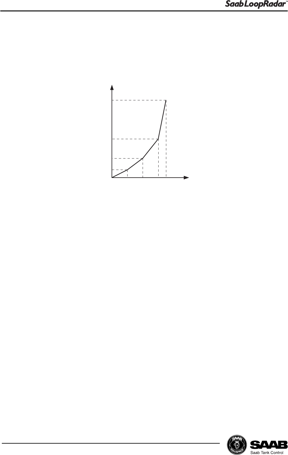
Tank Capacity Table
In order to obtain more accurate volume calculations you can create a table of
level values and corresponding volumes. A maximum of 20 points can be speci-
fied.
L1 L2 L3 L4
V2
V1
V3
V4
Volume
Level
Between the points linearly interpolated values are calculated.
At least two points must be entered for the Tank Capacity Table.
See chapter 5 Using the Display Panel for information on how to use the
Display Panel to set up the Loopradar transmitter for volume calculations.
4-7
Edition 1. Ref. No: 307010E
Transmitter Setup
4.4 Disturbance Echo Handling.
When disturbing echoes appear in the approved measuring range they can be
filtered out by setting up a Noise Table.
4.4.1 Noise Table
A Noise Table adjusts the threshold level at various parts of the measurement
range. By setting the threshold level to an appropriate value the disturbing echo
will be suppressed by the transmitter.
A Noise Table is defined by ullage points and signal amplitude threshold val-
ues. A maximum of 10 points can be specified. Linear interpolation is used be-
tween the points. Make sure that the noise table box around a disturbing echo is
big enough to hide the disturbing echo, see illustration below.
If a disturbing echo appears you should start by checking the ullage and the
corresponding amplitude of the detected signal. This provides information about
the position of the disturbance and the noise threshold required to suppress the
disturbing echo.
Note! The transmitter may temporarily loose track of the surface when it passes the noise threshold.
+ 5 dB
Signal Amplitude
Ullage (m)
Point 1
Point 2 Point 3
Point 4
Radar signal
Noise table
Point 1 Point 2
Point 3
Point 4
Signal Amplitude

4-8
Edition 1. Ref. No: 307010E
Transmitter Setup
5-1
Edition 1. Ref. No: 307010E
Using the Display Panel
5 Using the Display Panel
The Display Panel can be used for configuration of the LoopRadar transmitter as
well as for viewing tank data. The keys allow you to navigate through the different
menus and to enter desired values for various parameters.
5.1 Display Panel
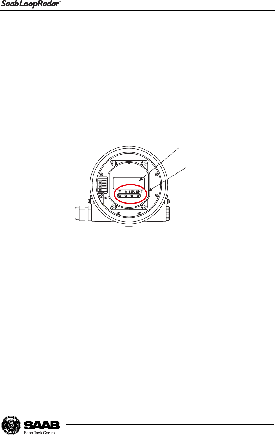
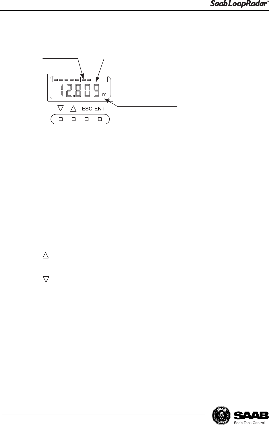
5.1.1 Display
Bar graph, measured data and measuement unit are displayed during normal
operation. The last measured value flashes on the display when the gauge is in
search mode.
When the Display Panel is used in configuration mode, menu number or regis-
tered data is displayed.
LCD
Keys
5-2
Edition 1. Ref. No: 307010E
Using the Display Panel
5.1.2 Keys
1. ENT (ENTER)
Press the Enter key to change from measurement mode to configuration
mode.
You can also use this key to move from the main menu to various sub menus.
By pressing the Enter key the cursor can be moved from one digit to the
other when entering a new parameter value.
2. ESC (ESCAPE)
Press the Escape key to change from configuration mode to measurement
mode.
Use the Escape key to move from sub menus to the main menu.
3. Up
The up button increases menu numbers and the value of a flashing digit.
4. Down.
The down button decreases menu numbers and the value of a flashing digit.
Measurement unit
Measured valueBar graph
5-3
Edition 1. Ref. No: 307010E
Using the Display Panel
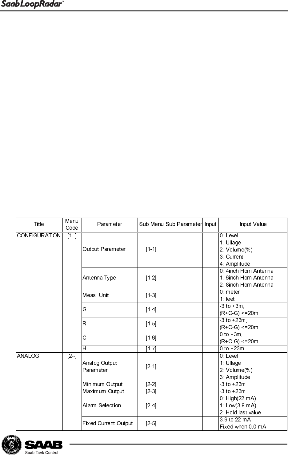
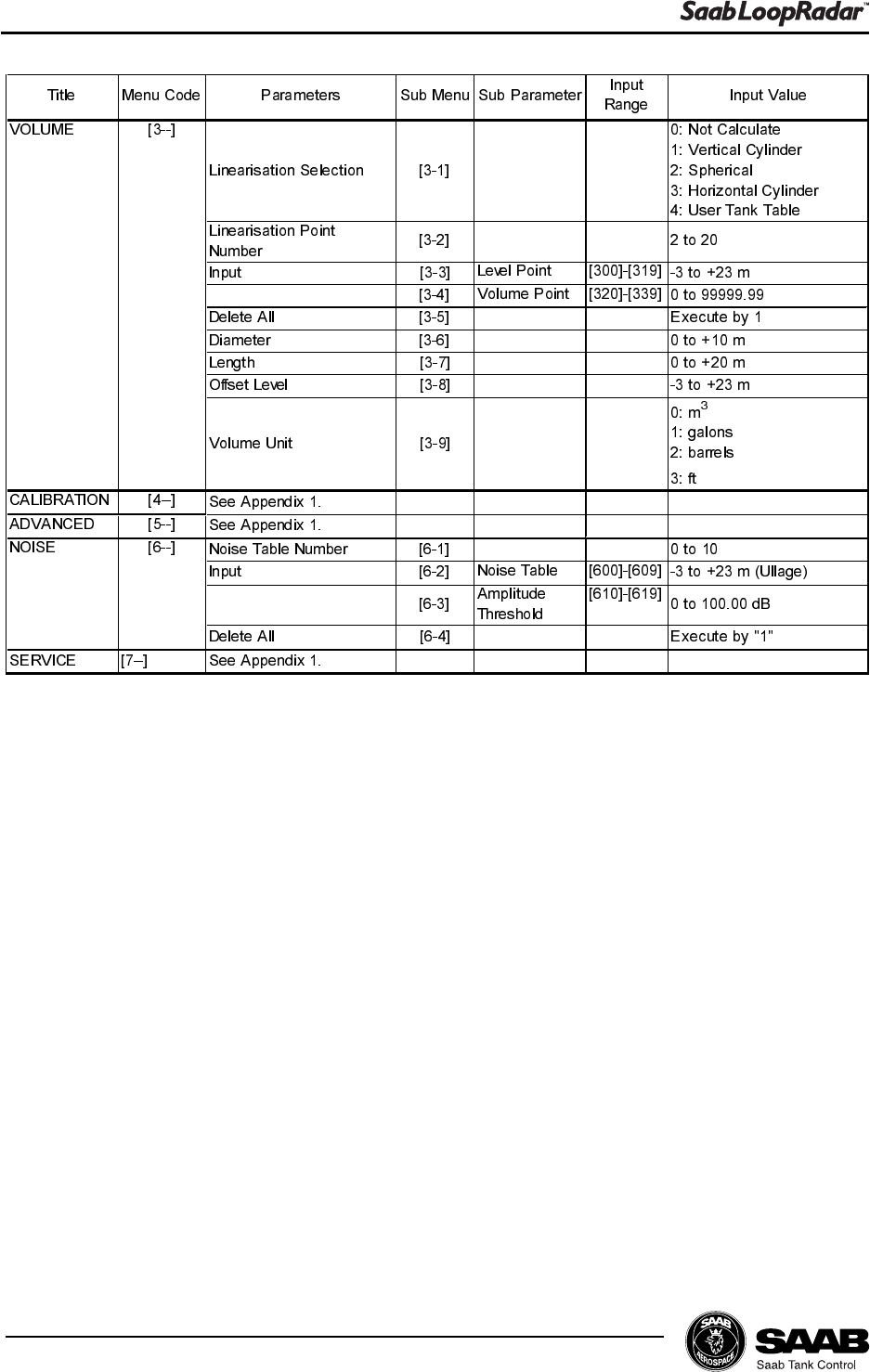
5.2 Basic Key Parameter List
By using the Display Panel keys you can make a complete configuration of the
LoopRadar. The various settings are grouped into seven main menus:
[1--] Configuration Basic configuration of tank dimensions, antenna type
and output parameter.
[2--] Analog Configuration of analog output signal.
[3--] Volume Specification of method for volume calculations.
[4--] Calibration Only for service actions. See Appendix 1 for further
information.
[5--] Advanced Only for service actions. See Appendix 1 for further
information.
[6--] Noise Option to create a noise table in order to suppress
distinct disturbing echoes.
[7--] Service Only for service actions. See Appendix 1 for further
information.
5-4
Edition 1. Ref. No: 307010E
Using the Display Panel
3
5-5
Edition 1. Ref. No: 307010E
Using the Display Panel
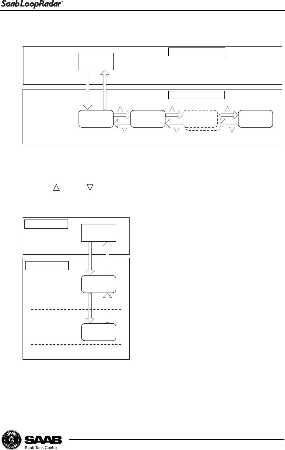
5.3 Navigating the Display Panel Menus
Measuring
Data
CONFIG
[1--] Analog
[2--] xx
[x--] Service
[7--]
ESC
ENT
Meas. Mode
Config. Mode
Main menu
Sub menu
Input stage
Measuring
Data
CONFIG
[1--]
Output
Parameter
[1-1]
ESC
ENT
ENT
ESC
Use the ENT and ESC keys to move up and down the menu tree.
Press the ENT key to switch from measurement mode to configuration mode.
Press the ESC key to return to measurement mode.
Use the and the keys to increment menu number.
Main menu
Measurement Mode
Configuration Mode

5-6
Edition 1. Ref. No: 307010E
Using the Display Panel
5.4 Configuration
Output parameter
1. Choose sub menu [1-1].
2. Choose one of the following parameters to be displayed on the panel:
0: Level, 1: Ullage, 2: Volume (%), 3: Current, 4: Amplitude.
Antenna type
1. Move to sub menu [1-2].
2. Choose one of the following antennas:
0: 4 inch Horn Antenna.
1: 6 inch Horn Antenna.
2: 8 inch Horn Antenna.
Measurement Unit
1. Choose sub menu [1-3].
2. Choose one of the following options:
0: meter.
1: feet.
Tank Distances
1. Choose sub menu [1-5] and enter the tank height R. Measure R from the
LoopRadar Reference Point to the tank bottom.
2. If the Zero Level reference point is located above the tank bottom, choose
sub menu [1-6]. (This may be the case if for example a Datum Plate is
used).
In order to be able to measure levels below the Zero Level, enter the C
distance from the Zero Level to the tank bottom.
If C is set to 0, levels below the zero reference point will be presented as 0.
See chapter 4.1.2-3 for more information on the definition of tank geometry pa-
rameters.
Hold Off Distance
1. Choose sub menu [1-7].
2. Enter the Hold Off distance H. The Hold Off distance is defined as the dis-
tance from the LoopRadar Reference Point to the upper limit of the Ap-
proved Measurement Range.
See chapter 4.1 for further information on the definition of tank geometry.
5-7
Edition 1. Ref. No: 307010E
Using the Display Panel
Example-1
To set the tank height R to 6.275m do the following:
.H\ 'LVSOD\
P 0HDVXULQJ/HYHOP1RUPDORSHUDWLRQPRGH
(17 >@ 0DLQPHQXQXPEHU&RQILJXUDWLRQPRGH
(17 >@
D>@
D>@
D>@
D>@
(17 'HIDXOWYDOXH
(17 ³´IODVKLQJ
Dòò3XVKWLPHV
(17
¶ò
(17
Dò
(17
¶ò
(17
(17 &KHFNWKDWILJXUHVVWRSIODVKLQJ
(6& >@
(6& >@
(6& 0HDVXULQJ/HYHOP1RUPDORSHUDWLRQPRGH
>;;@
0DLQPHQXQXPEHU
6XEPHQXQXPEHU

5-8
Edition 1. Ref. No: 307010E
Using the Display Panel
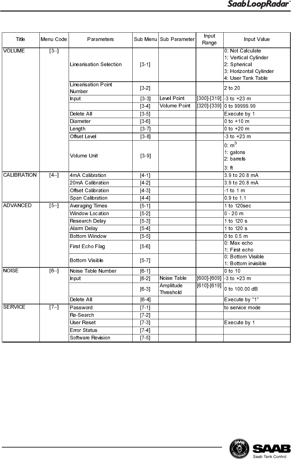
5.5 Volume Calculation
Tank Type
1. Choose sub menu [3-1] to specify calculation method.
2. Choose one of the following options:
0 No volume calulation is performed.
1Volume calculation is based on the shape of a Vertical Cylinder.
2Volume calculation is based on the shape of a Spherical tank.
3 Volume calculation is based on the shape of a Horizontal
Cylinder.
4Volume calculation is based on a table of level values and corre-
sponding volumes. See section Tank Capacity Table for further
information.
Tank Dimensions
Diameter Choose sub menu [3-6] to specify tank diameter for
Vertical Cylinder or Spherical tank.
Length Choose sub menu [3-7] to specify length for Hori-
zontal Cylinder tank.
Offset
Choose sub menu [3-8] to specify a level offset if you do not want the volume
to be zero at the Zero Level reference point.
Tank Capacity Table
1. Choose sub menu [3-2] in order to specify the number of linearization points
for the Tank Capacity Table.
2. Choose sub menu [3-3] and enter the level values. Enter as many points as
specified in sub menu [3-2].
3. Choose sub menu [3-4] and enter the volumes that correspond to the level
values entered in sub menu [3-3].
4. Choose sub menu [1-1] to choose volume as output parameter on the Dis-
play Panel.
5. Return to measurement mode.
5-9
Edition 1. Ref. No: 307010E
Using the Display Panel
Example-2
To set the second Volume point to 2345.67m3 do the following:
A volume point can be set from 00000.00 to 99999.99.
.H\ 'LVSOD\
0HDVXULQJ/HYHOP1RUPDORSHUDWLRQPRGH
(17 >@
Dò >@ 9ROXPH0DLQPHQX
(17 >@
Dò > @ 9ROXPHSRLQW6XEPHQX
(17 > @ 9ROXPHSRLQW
D> @ 9ROXPHSRLQW
(17 'HIDXOWYDOXH
(17 ³´LVIODVKLQJ
Dò 3XVKWLPHV
(17
Dò 3XVKWLPHV
(17
Dò 3XVKWLPHV
(17
Dò 3XVKWLPHV
(17
Dò 3XVKWLPHV
(17
Dò 3XVKWLPHV
(17
(17 &KHFNWKDWILJXUHVVWRSIODVKLQJ
(6& >@
(6& >@
(6& >@
(6& 0HDVXULQJ/HYHOP1RUPDORSHUDWLRQPRGH

5-10
Edition 1. Ref. No: 307010E
Using the Display Panel
5.6 Setting up the Analog Output
Output parameter
1. Choose sub menu [2-1].
2. Choose one of the following parameters as source signal for the Analog
Output:
0: Level,
1: Ullage,
2: Volume (%),
3: Amplitude.
Output range
1. Choose sub menu [2-2] to enter the Minimum Output value corresponding to
the Analog Output value 4 mA.
2. Choose sub menu [2-3] to enter the Maximum Output value corresponding to
the Analog Output value 20 mA.
Setting up the Alarm Mode
1. Choose sub menu [2-4] to specify Alarm mode for the Analog Output.
2. Choose one of the following options:
0: High. The current is fixed at 22 mA when an alarm is activated.
1: Low. The current is fixed at 3.9 mA when an alarm is activated.
2: Hold Last Value. The analog output current is fixed at the present value.
5-11
Edition 1. Ref. No: 307010E
Using the Display Panel
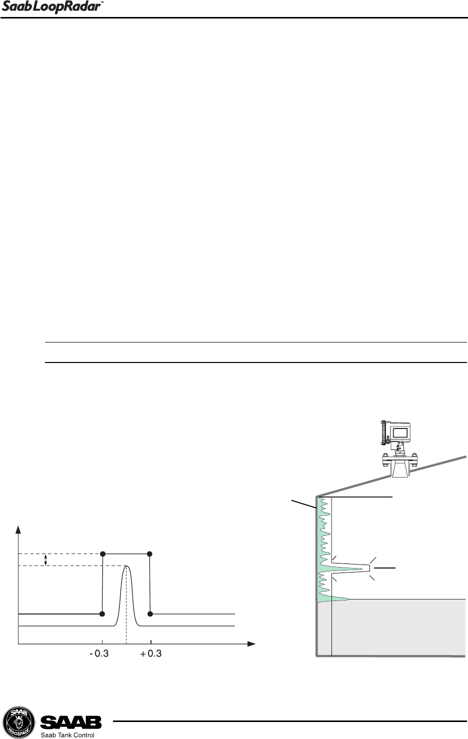
5.7 Disturbance Echo Handling
5.7.1 Setting up a Noise Threshold Table
If the transmitter has locked to a disturbing echo you can create a Noise Threshold
Table in order to suppress the disturbing echo:
1. Do the following to check where the disturbing echo is located and the corre-
sponding radar signal amplitude:
1. Choose sub menu [1-1] and set the Output Parameter to Ullage.
2. Note the Ullage value.
3. Choose sub menu [1-1] and set the Output Parameter to Amplitude.
4. Note the Amplitude value.
5. Choose sub menu [1-1] and set the Output Parameter to the desired
value (see the Key Parameter list).
Now you can start creating the noise table.
2. Choose sub menu [6-1].
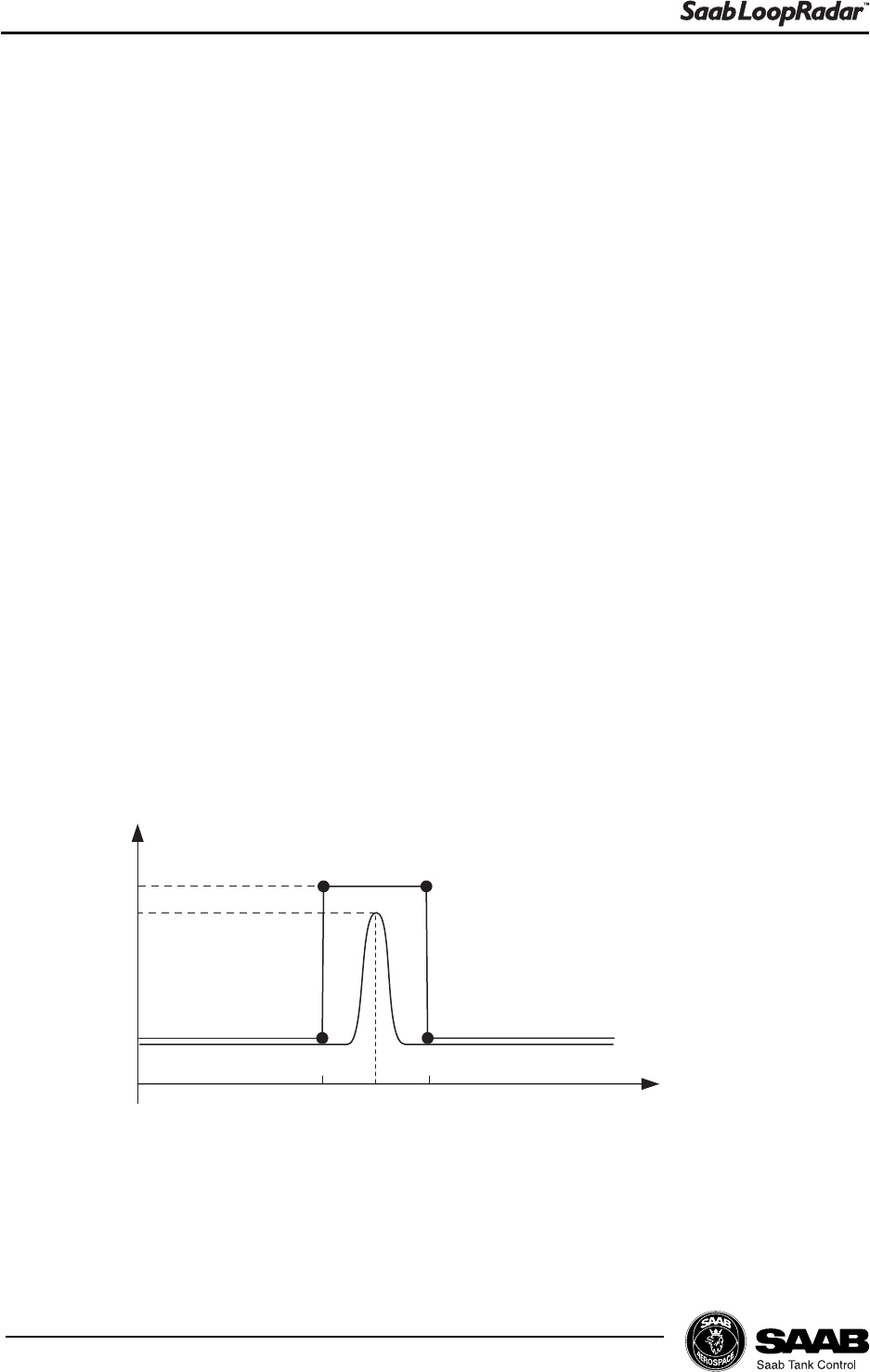
3. Specify the number of points you want to use for the Noise Threshold Table.
In order to suppress a single peak signal four points is sufficient. For more
complicated noise tables you can use up to ten points.
4. Choose sub menu [6-2] and enter the ullage values that correspond to the
desired noise table break points. The points must be added in consecutive
order. Use a margin of ± 0.3 meter, see illustration below.
5. Choose sub menu [6-3] and enter the amplitude threshold values that corre-
spond to the desired noise table break points. A margin of + 5 dB is suffi-
cient in most cases.
+ 5 dB
Signal Amplitude
Ullage
Point 1
Point 2 Point 3
Point 4
6. Return to measuring mode and check that the transmitter detects the product
surface.
5-12
Edition 1. Ref. No: 307010E
Using the Display Panel
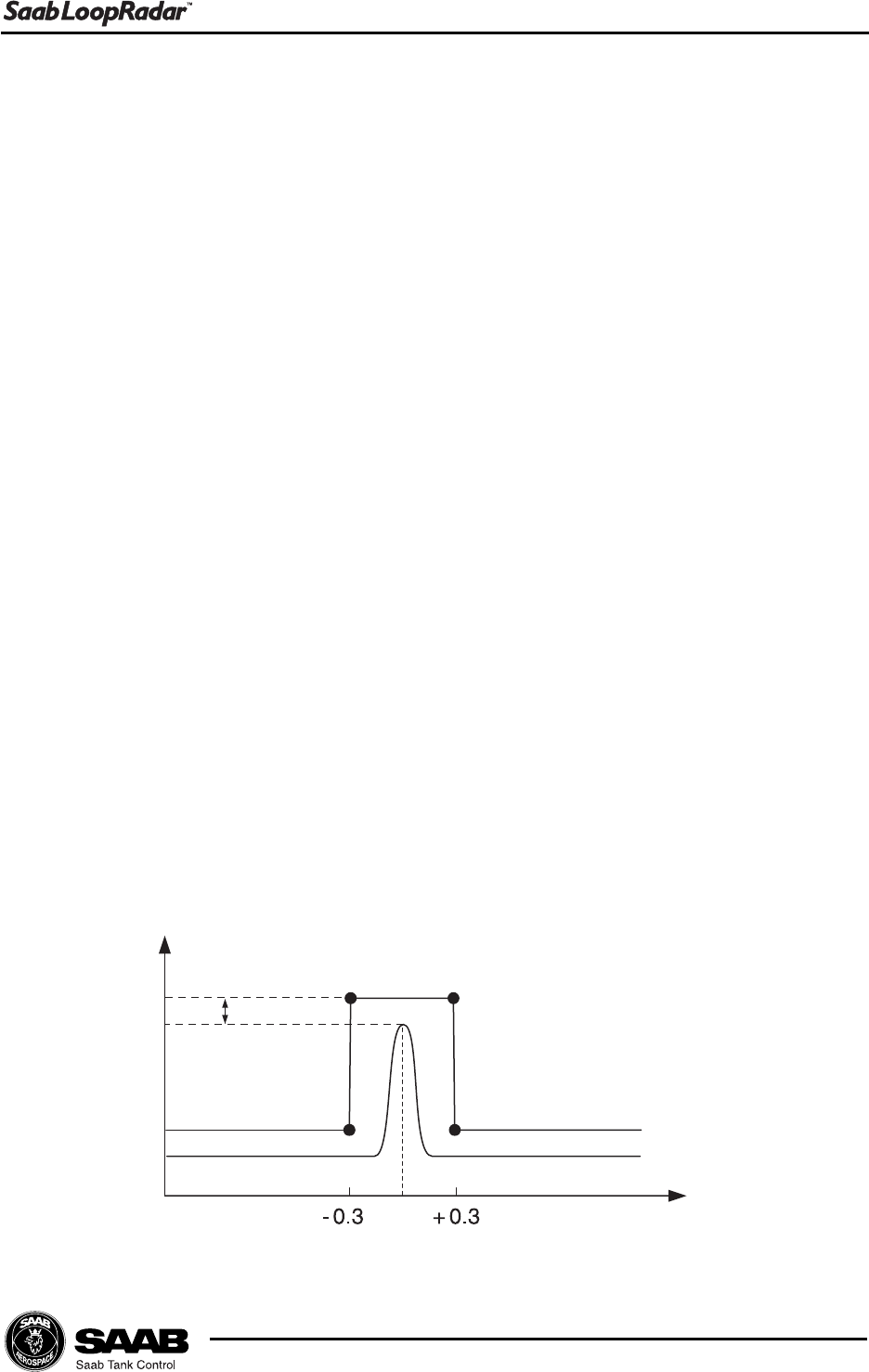
Example.
A disturbing echo is located at Ullage=3 m. The signal amplitude of the disturbing
echo is 3 dB. The following Noise Theshold Table is created to suppress this
echo:
Sub menu [6-1]: 4 (4 points in the noise table).
Sub menu [6-2]:
Point 1: [600]=2.7.
Point 2: [601]=2.7.
Point 3: [602]=3.3.
Point 4: [603]=3.3.
Sub menu [6-3]:
Point 1: [610]=0 dB.
Point 2: [611]=8 dB.
Point 3: [612]=8 dB.
Point 4: [613]=0 dB.
3 dB
0 dB
8 dB
2.7 3 3.3
Point 1
Point 2 Point 3
Point 4
Ullage
Signal Amplitude

6-1
Edition 1. Ref. No: 307010E
Technical Information
6 Technical Information
System
Operating frequency 5.8 GHz
6.3 GHz (USA only)
Half-power beam width 4 " Cone antenna: 34 deg
6 " Cone antenna: 22 deg
8 " Cone antenna: 17 deg
Measuring range Max. 20 m (65 ')
Serial communication HART communication
Key switch 4 keys for configuration
Display 5 digits LCD and bar graph
Power
Supply voltage 18..30 VDC(Ex) / 18..36 VDC(Non-Ex)
Specification for HART Ripple: 47..125 Hz
Vpp=200 mV (measured at 500 ohm)
Max.noise: 500 Hz..10 kHz
Vrms=2.2 mV (measured at 500 ohm)
Output
Variable Ullage / Level / Volume / Current /
Signal amplitude
Unit Level, Ullage: m/ft. Volume: %. Current: mA.
Signal amplitude: dB.
Signal type Analog 4..20 mA, HART
Resolution Analog: 4 mA
Digital: 1 mm (0.04")
Update time 1 s
Averaging time 1..120 s
6-2
Edition 1. Ref. No: 307010E
Technical Information
Signal on alarm Hold/Low (3.9 mA)/High (22 mA)
Load Minimum load for HART communication 250
ohm.
Accuracy
Measured error *)±10 mm (0.4")
Linearity *)±10 mm (0.4")
Repeatability *)±10 mm (0.4")
Ambient temperature effect ±0.01% / 10 K
*): Free-space reflection from flat metal surface, ambient
temperature 25 °C (77 °F), atmospheric pressure.
Environment resistance
Ambient temperature -40..70 °C (-40..158 °F)
Display Unit -20..70 °C (-4..158 °F)
Storage temperature -40..80 °C (-40..176 °F)
Tank temperature -40..150 °C (-40..302 °F)
Tank pressure -0.1..1.0 MPa (-14..145 Psi)
Water protection Designed for IP65, NEMA 4
Vibration resistance IEC 68-2-6 /1G
Standard
Ex ia
Input Voltage (V)
Load (Ohm)

6-3
Edition 1. Ref. No: 307010E
Technical Information
Electromagnetic compatibility Emission: EN 50081-1
Immunity: EN 50082-2
Cable Connection
Cable type Shielded twisted pair
Cross-section area of cable: 0.2..2.5 mm2,
(AWG24..14)
Cable entry 2-M20X1.5, NPT 1/2" (cable dia. 5..9 mm)
Ground cable Max. 4 mm2
Material
Transmitter Case Aluminum
Cone antenna 316L stainless steel
Sealing parts PTFE, Viton O-ring
Certificate and Approvals
Hazardous area certification 0518 II 1 G
- EEx ia IIC T4. (Tamb - 40 ºC to + 70 ºC)
- Ui=30 V, Ii=110 mA, Pi=825 mW, Li=0,
Ci=see certificate
- Certificate No. SIRA 00ATEX2052X
FM: IS Class I, Division 1, Group A-D
(In preparation)
Telecommunication BZT (in preparation)
FCC (in preparation)

6-4
Edition 1. Ref. No: 307010E
Technical Information

7-1
Edition 1. Ref. No: 307010E
Troubleshooting
7 Troubleshooting
LCD status messages
[E--] Normal Operation
[E01] Internal Error. Serious error. Please contact service
department.
[E02] Memory Error. Serious error. Please contact service
department.
[E03] Receive Error. No measure data. Please contact service
[E04] Tank CapacityTable Error. Incorrect setting of Tank Capacity Table.
[E05] Noise Table Error. Incorrect setting of noise table.
[E99] Searching. Searching for Echo

7-2
Edition 1. Ref. No: 307010E
Troubleshooting

Index-I
Edition 1. Ref. No: 307010E
Index
Index
A
Advanced............................................................................................................................................ 5-3
Analog ...................................................................................................................................... 5-3, A1-1
Analog Output ............................................................................................................................ 4-4, 5-10
alarm ............................................................................................................................................... 4-4
alarm mode ................................................................................................................................... 5-10
calibration ...................................................................................................................................... 5-10
Maximum Output ............................................................................................................................. 4-4
Minimum Output .............................................................................................................................. 4-4
output parameter ........................................................................................................................... 5-10
output range .................................................................................................................................. 5-10
source ............................................................................................................................................. 4-4
Analog Output Parameter .................................................................................................................... 4-4
Antenna Type ...................................................................................................................................... 4-2
Antenna type....................................................................................................................................... 5-6
C
C distance........................................................................................................................................... 4-3
Cable .................................................................................................................................................. 3-3
Cable entry ......................................................................................................................................... 3-3
Calibration ........................................................................................................................................... 5-3
Communication ................................................................................................................................... 1-1
Configuration ....................................................................................................................................... 5-6
current output ...................................................................................................................................... 1-1
D
Display Panel ...................................................................................................................................... 5-1
keys ................................................................................................................................................ 5-1
menus ............................................................................................................................................. 5-5
Disturbance Echo Handling ............................................................................................................... 5-11
Disturbance echo handling .................................................................................................................. 4-7
E
ENT .................................................................................................................................................... 5-2
ENT key ............................................................................................................................................. 5-5
ESC .................................................................................................................................................... 5-2
ESC key ............................................................................................................................................. 5-5
G
G distance .......................................................................................................................................... 4-3
Grounding ........................................................................................................................................... 3-3
H
HART .................................................................................................................................................. 1-1
minimum load .................................................................................................................................. 3-3
Hold Off .............................................................................................................................................. 4-2
Hold Off Distance................................................................................................................................ 5-6
Horizontal cylinder Tank ...................................................................................................................... 4-5

Index-II
Edition 1. Ref. No: 307010E
Index
K
Key Parameter List .................................................................................................................... 5-3, A1-1
Keys ................................................................................................................................................... 5-2
L
Load .................................................................................................................................................... 3-3
Loop-Power ......................................................................................................................................... 1-1
Loop-powered ...................................................................................................................................... 1-1
M
Maximum load .................................................................................................................................... 3-3
Measurement principle ........................................................................................................................ 1-2
Measurement Unit ........................................................................................................................4-2, 5-6
Minimum load ..................................................................................................................................... 3-3
N
Noise .................................................................................................................................................. 5-3
Noise Table ......................................................................................................................................... 4-7
Noise threshold table ........................................................................................................................ 5-11
O
Output Parameter ................................................................................................................................ 4-2
Output parameter ................................................................................................................................ 5-6
P
PLC .............................................................................................................................................1-1, 3-2
Power supply....................................................................................................................................... 3-3
power supply ................................................................................................................................1-1, 3-2
pulsed microwaves ............................................................................................................................. 1-1
S
Service ............................................................................................................................................... 5-3
Spherical Tank..................................................................................................................................... 4-5
T
Tank Capacity Table ............................................................................................................................ 4-6
Tank Distances ................................................................................................................................... 5-6
Tank height R ...............................................................................................................................4-2, 4-3
Transmitter Setup ................................................................................................................................ 4-1
V
Vertical cylinder Tank .......................................................................................................................... 4-5
Volume................................................................................................................................................ 5-3
Volume Calculation ............................................................................................................................. 5-8
level offset ...................................................................................................................................... 5-8
tank dimensions .............................................................................................................................. 5-8
tank type ......................................................................................................................................... 5-8
Volume calculation .......................................................................................................................1-1, 4-5
Z
Zero Level Reference Point ................................................................................................................. 4-3
A1-1
Edition 1. Ref. No: 307010E
Appendix 1: Key Parameters
Appendix 1: Key Parameters
By using the Display Panel keys you can make a complete configuration of the
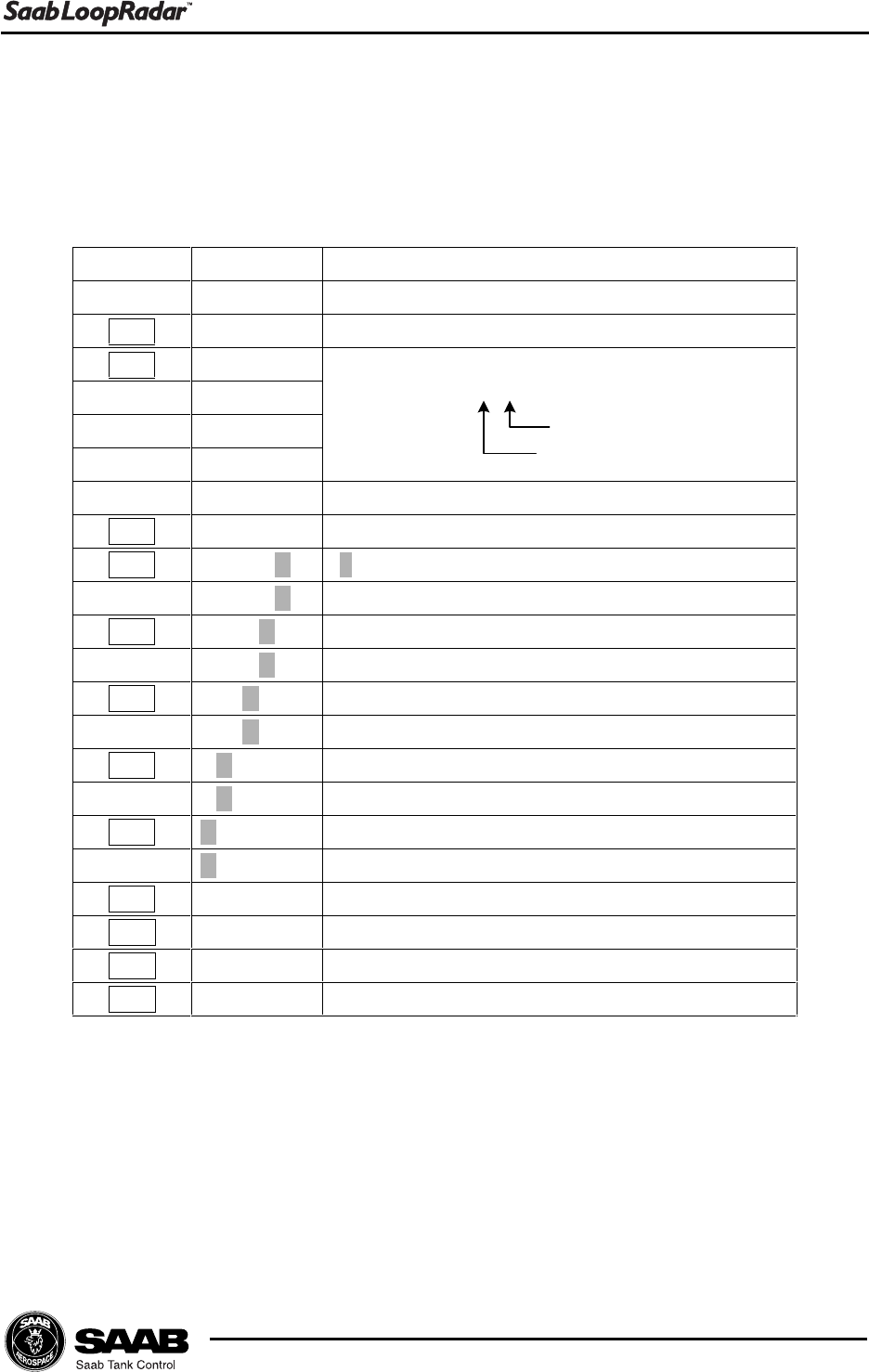
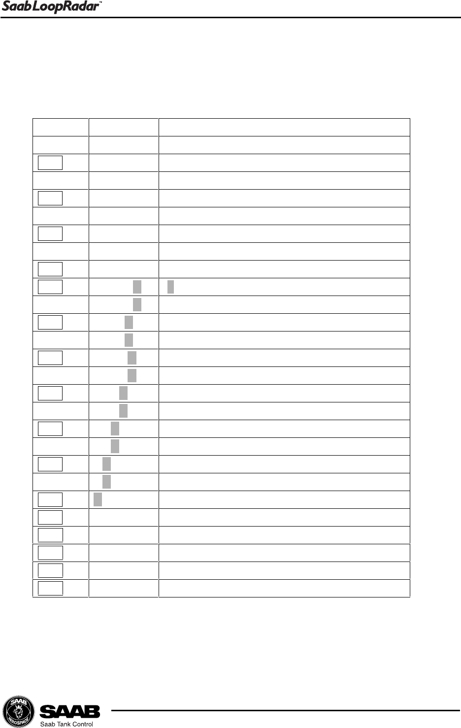
LoopRadar. The various settings are grouped into seven main menus:
[1--] Configuration Basic configuration of tank dimensions, antenna
type and output parameter.
[2--] Analog Configuration of analog output signal.
[3--] Volume Specification of method for volume calculations.
[4--] Calibration Calibration of analog output range and calibration of
level measurements.
[5--] Advanced Advanced configuration for improving measurement
performance in difficult environments.
[6--] Noise Option to create a noise table in order to suppress
distinct disturbing echoes.
[7--] Service Special functions for service actions.
$QWHQQD7\SH >@
LQFK+RUQ$QWHQQD
LQFK+RUQ$QWHQQD
LQFK+RUQ$QWHQQD
0HDV8QLW >@ PHWHU
IHHW
* >@ WRP
5&* P
5 >@ WRP
5&* P
& >@ WRP
5&* P
+ >@ WRP
$QDORJ2XWSXW
3DUDPHWHU >@
/HYHO
8OODJH
9ROXPH
$PSOLWXGH
0LQLPXP2XWSXW >@ WRP
0D[LPXP2XWSXW >@ WRP
$ODUP6HOHFWLRQ >@
+LJKP$
/RZP$
+ROGODVWYDOXH
)L[HG&XUUHQW2XWSXW >@ WRP$
)L[HGZKHQP$
&21),*85$7,21 >@
>@$1$/2*
7LWOH 0HQX
&RGH ,QSXW9DOXH
2XWSXW3DUDPHWHU >@
/HYHO
8OODJH
9ROXPH
&XUUHQW
$PSOLWXGH
3DUDPHWHU 6XE0HQX 6XE3DUDPHWHU ,QSXW
A1-2
Edition 1. Ref. No: 307010E
Appendix 1: Key Parameters
3

Saab Tank Control Local Representative:
First edition. February 2000.
Ref. no. 307010 E.
Saab Tank Control
Box 13045
S-402 51 Göteborg
SWEDEN
Phone: + 46 31 337 00 00
Fax: + 46 31 25 30 22
e-mail: sales.stc@marine.combitech.se
Internet: http://www.saab.tankradar.com
MFR. TOKIMEC INC.
Control Systems Division
2-16-46, Minami-kamata, Ohta-ku,
Tokyo 144-8551
JAPAN
Phone: + 81 3 3737 8631
Fax: + 81 3 3737 8666