Rosemount Tank Radar PROX Radar Level Gauge User Manual Cover Front
Rosemount Tank Radar AB Radar Level Gauge Cover Front
UserManual.wiki
>
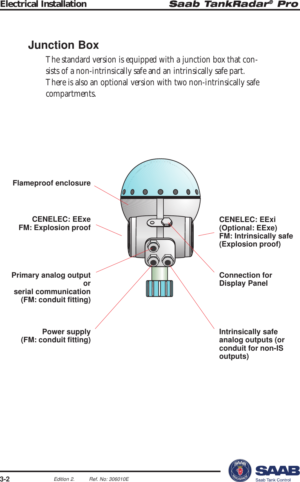
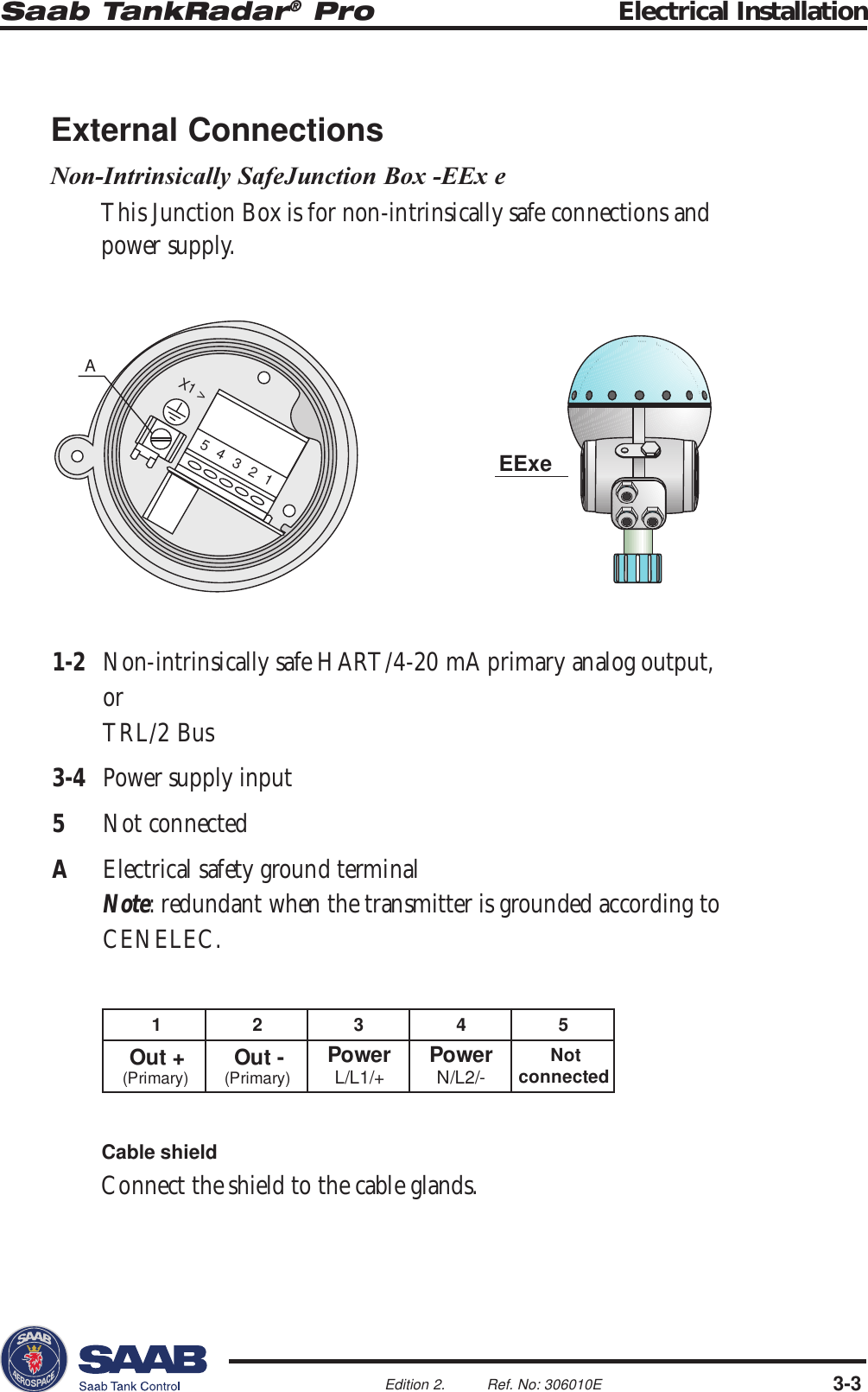
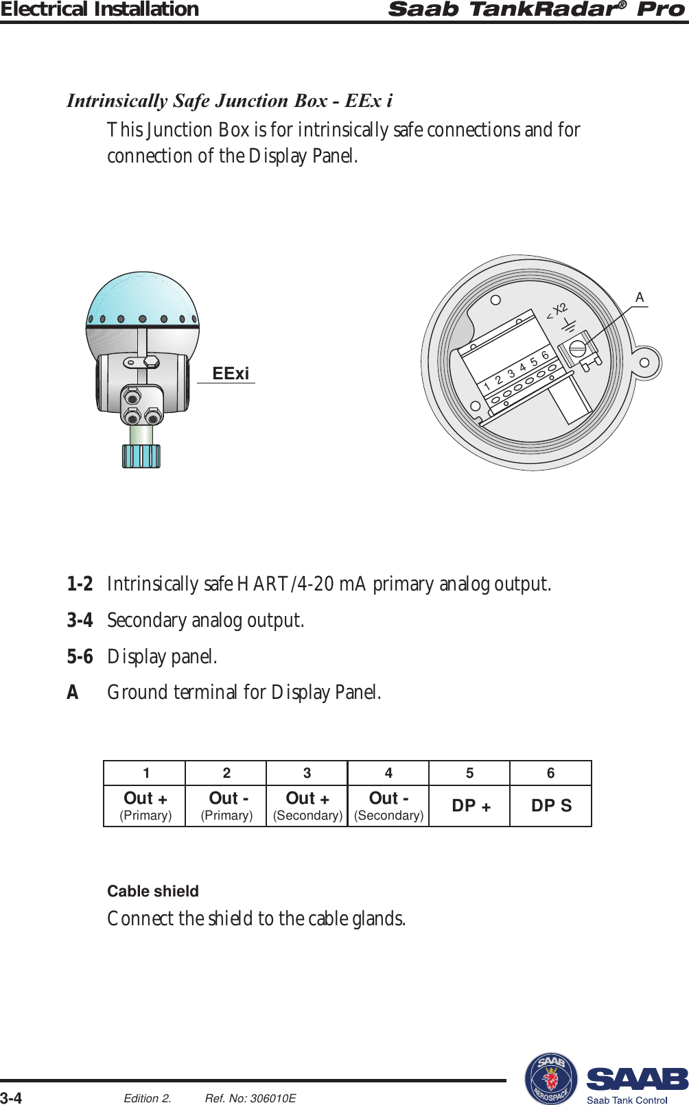
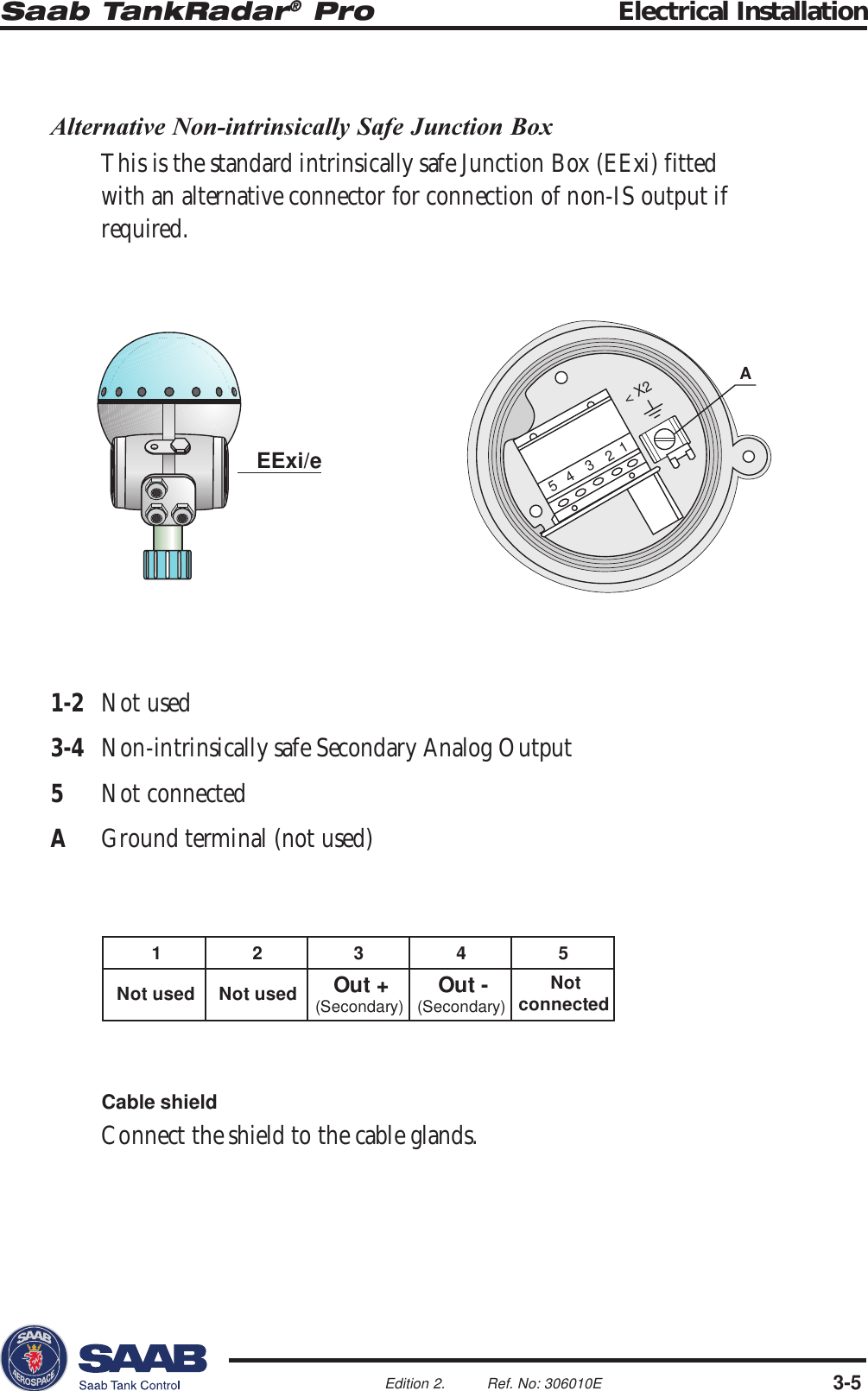
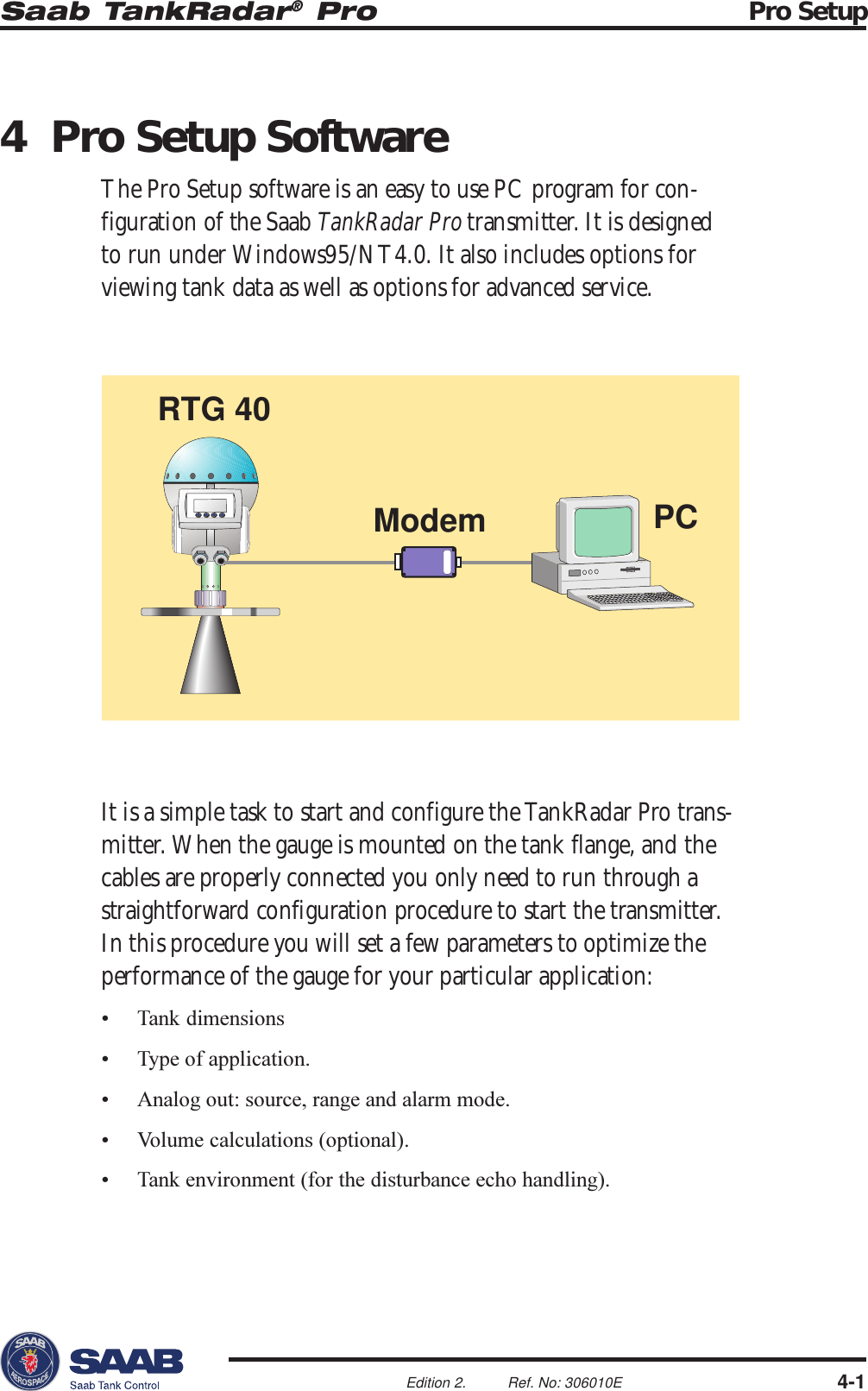
Rosemount Tank Radar
>
PROX User Manual
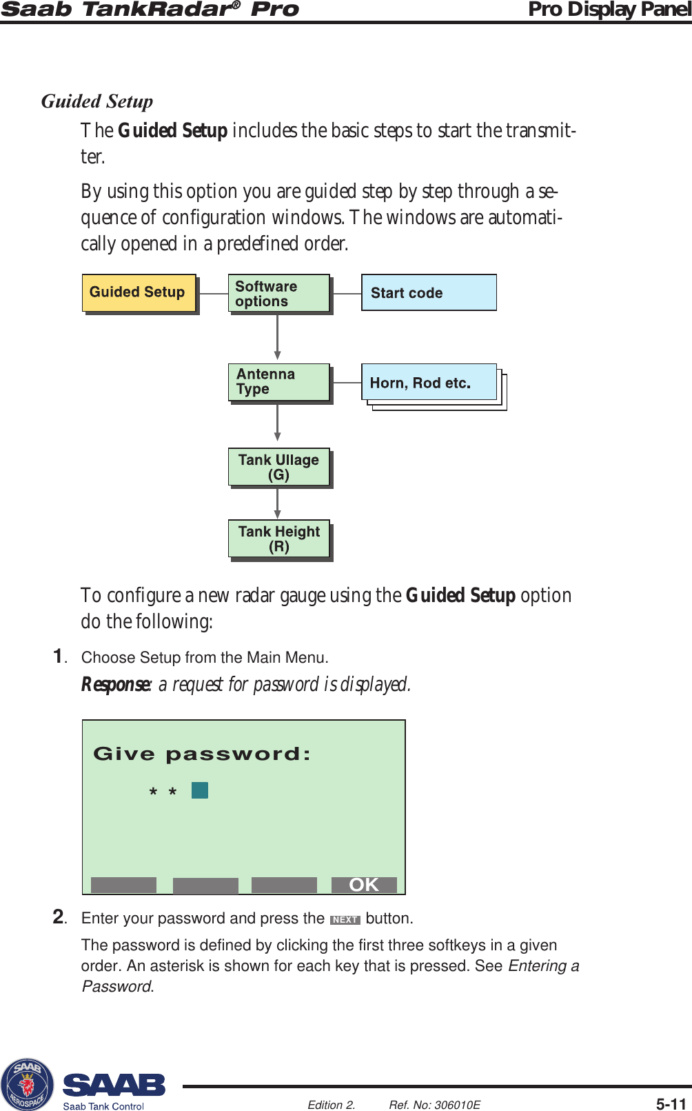
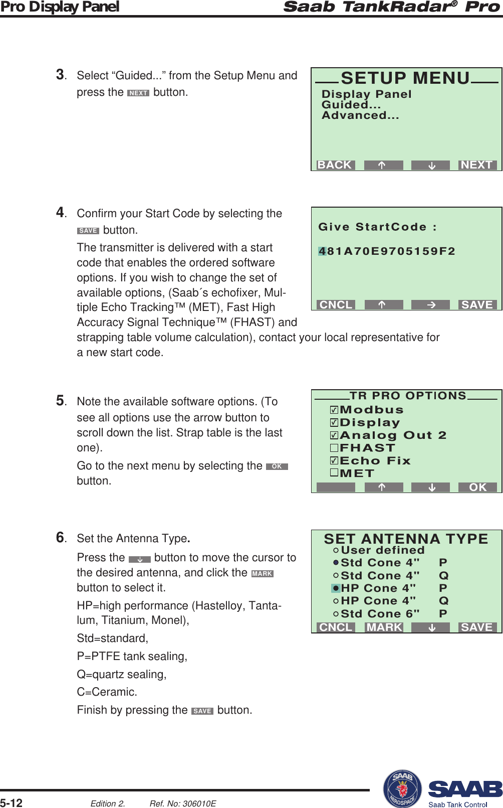
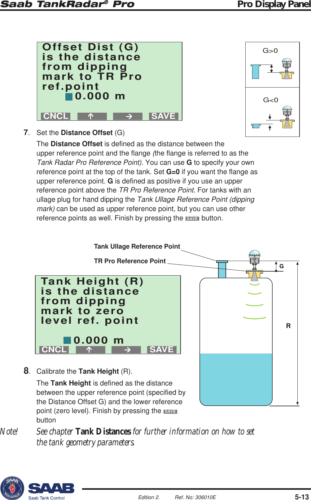
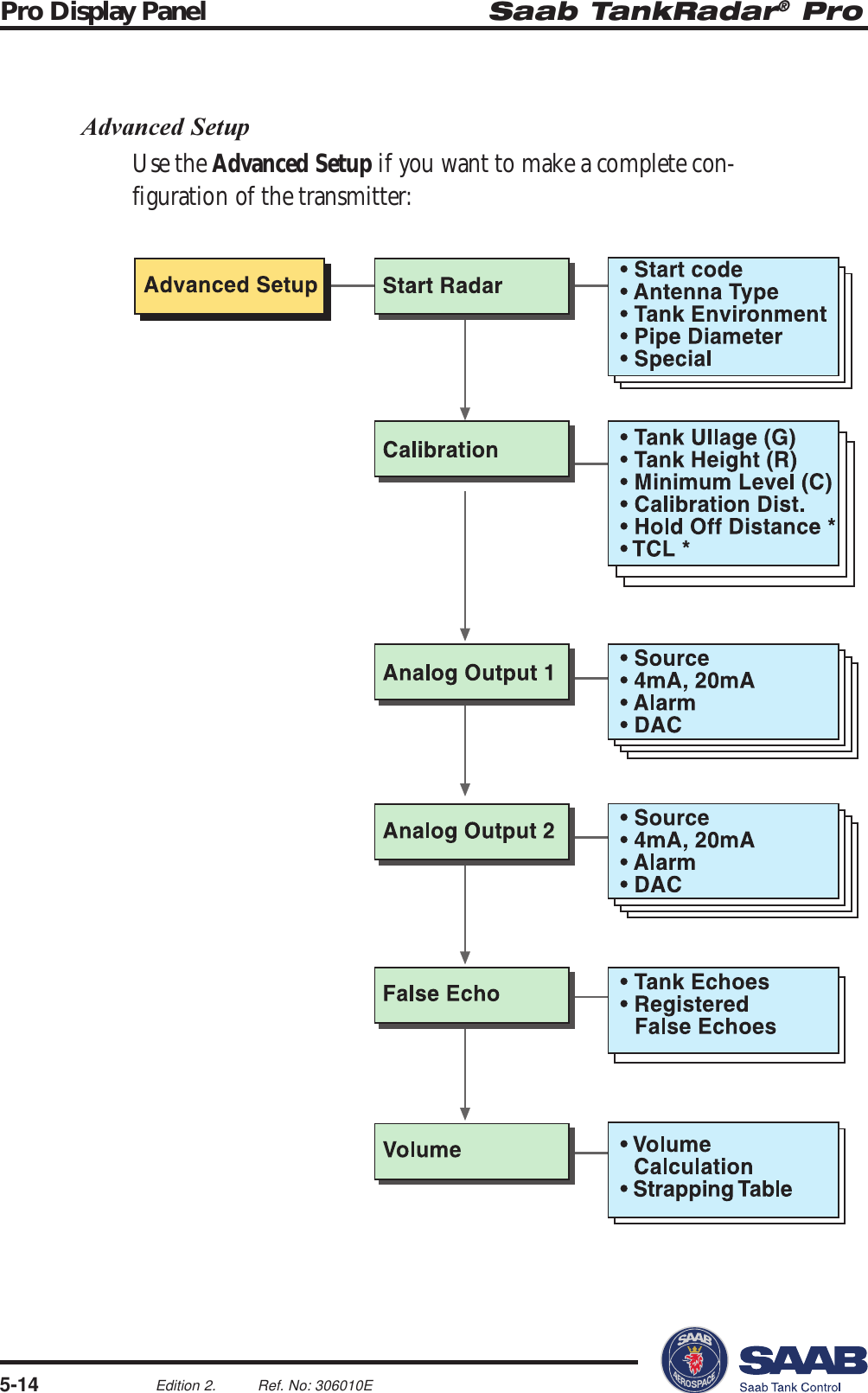
Users guide
Navigation menu
Upload a User Manual
Namespaces
Wiki Guide
HTML
PDF
Info
Views
User Manual
Discussion / Help
Navigation
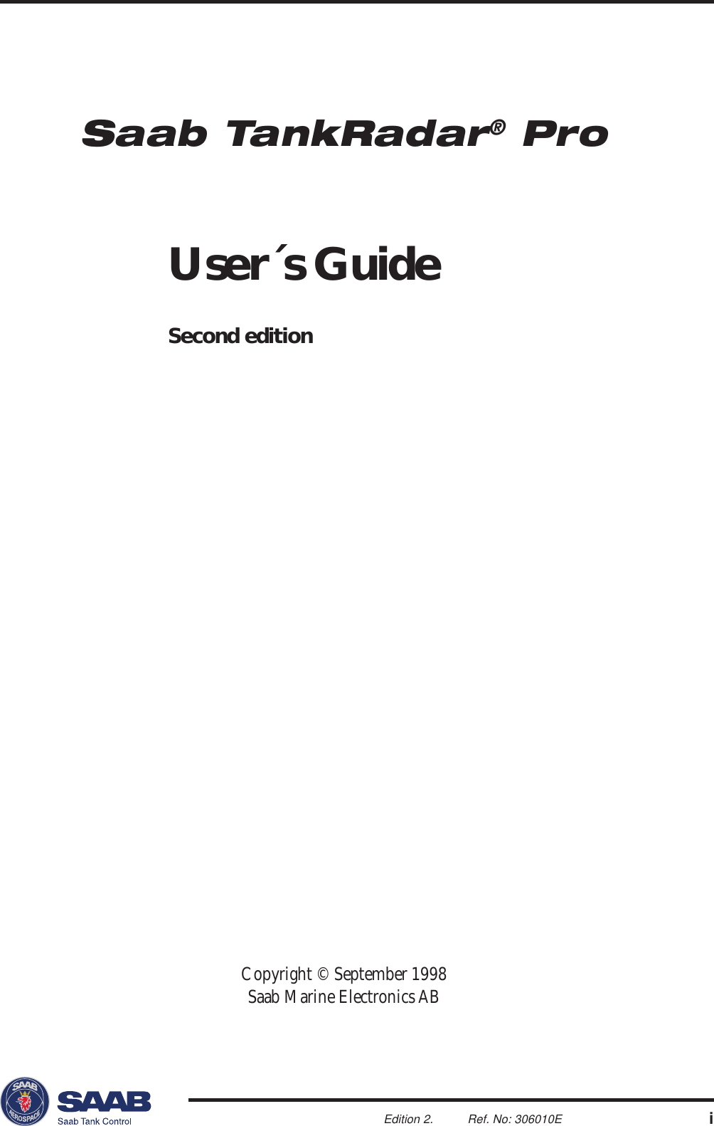

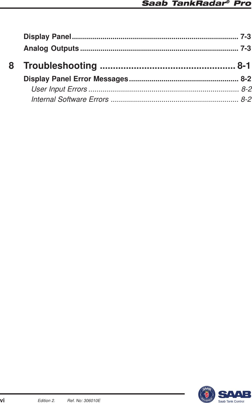
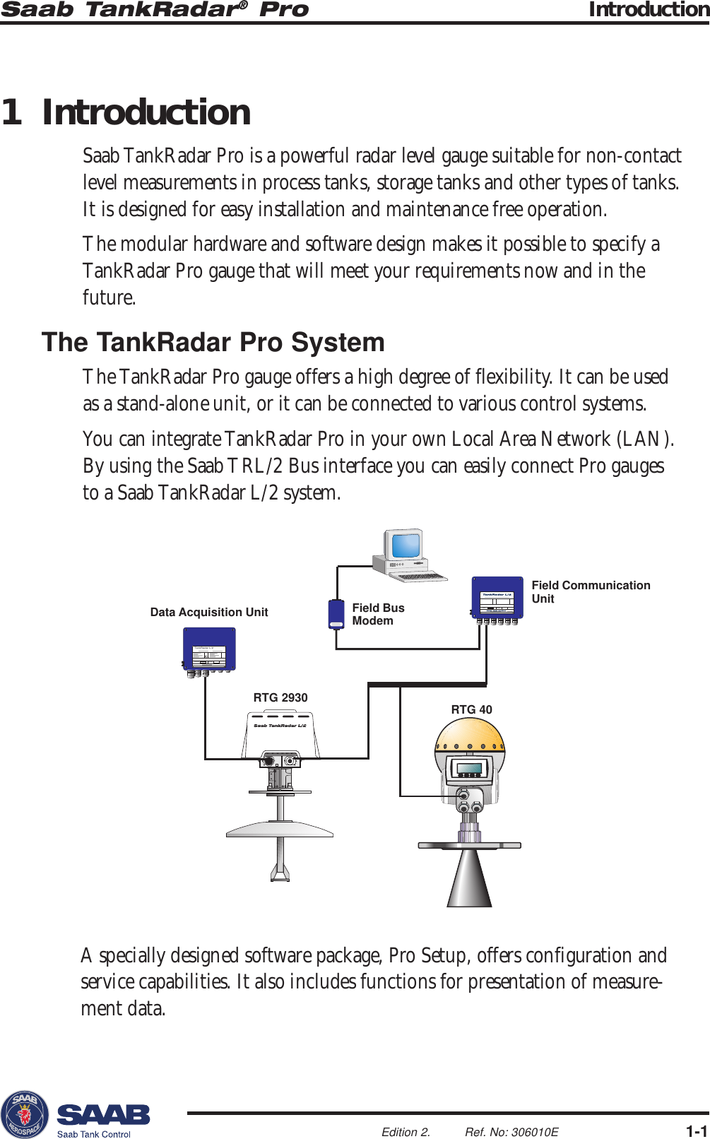
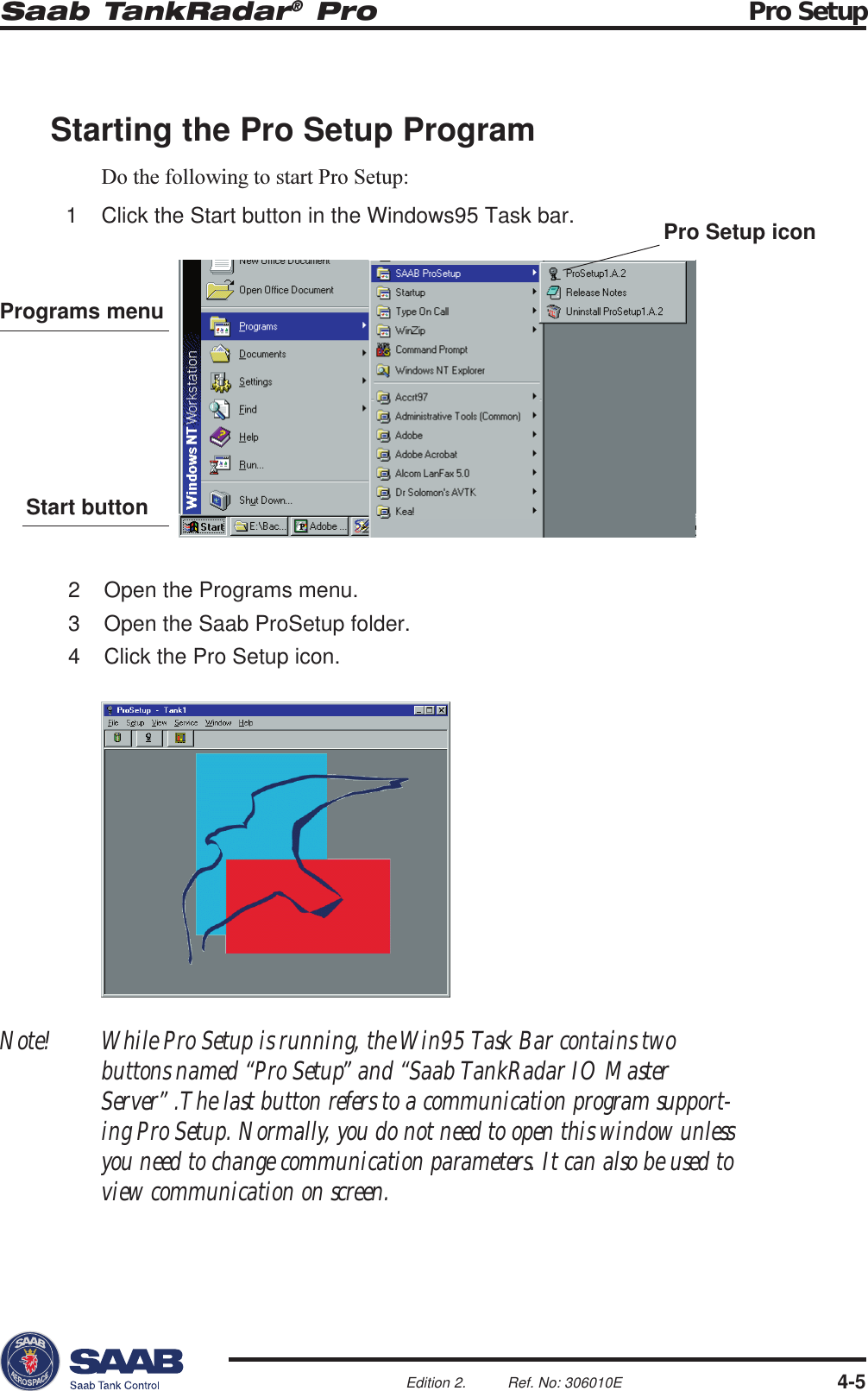
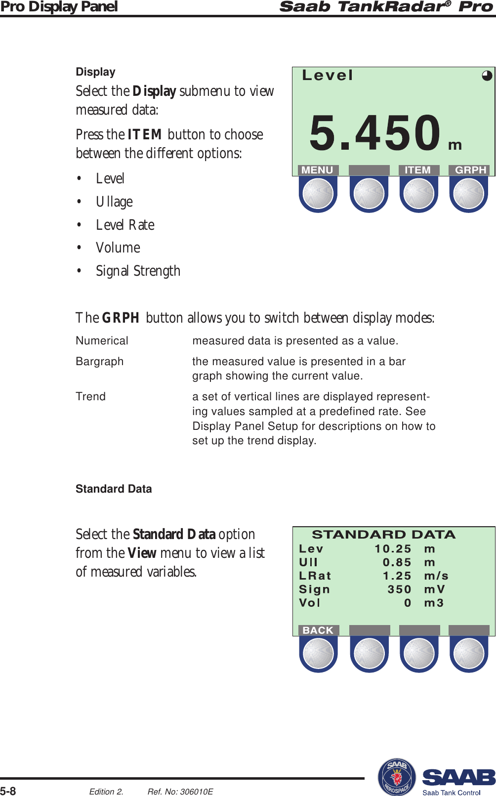
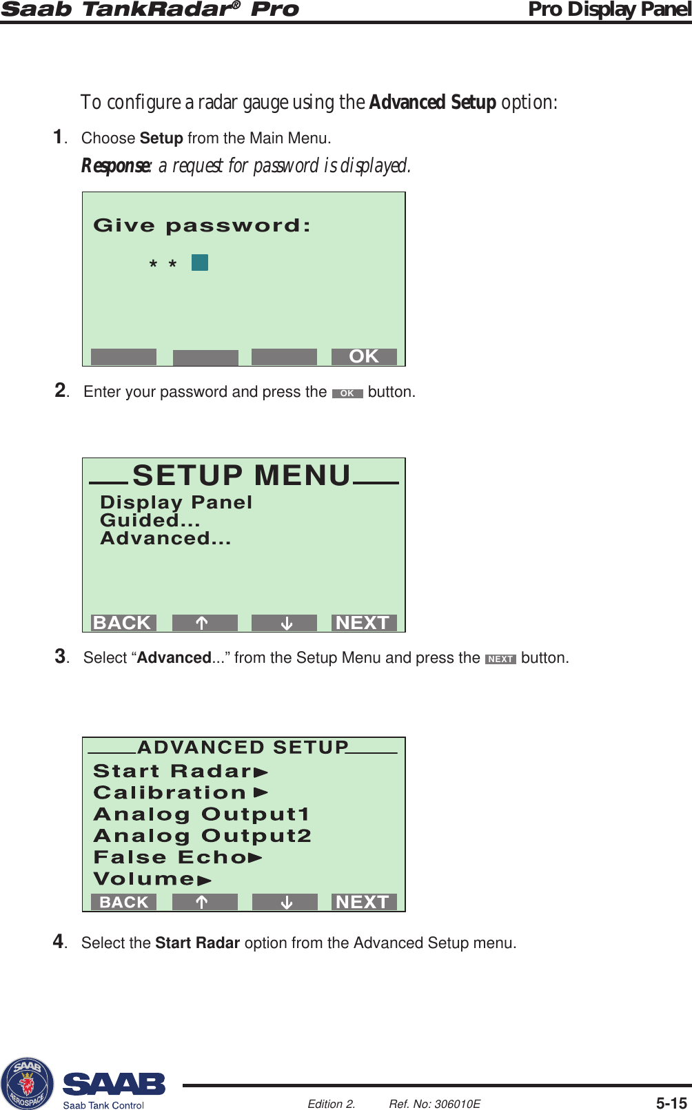
![Saab TankRadar® Pro Electrical Installation3-1Edition 2. Ref. No: 306010EFCC ID K8CPROEEx de[ib]ib IIC T4(Tamb-40°C, +70°C)I. S. Options:DI 40 HM 40+IS 40 XA 40+IS 40Non-I.S. Options/Power Supply:AC 40 (85-260 VAC, 10W)Serial No:1434SCS Ex97D1028NEPASOUVRIRSOUSTENSION.HAZARDOUSATMOSPHERESDONOTOPENWHENENERGIZED.TOPREVENTIGNITIONOFI II III IV VApprovalPower SupplyPrimary OutputDisplay PanelSecondary Output3 Electrical InstallationIdentication ofInstalled OptionsI ApprovalC CenelecFFMP PTBX Other certificatesII Power SupplyA 100 - 240 VAC nominal powerD 24 -48 VDC nominal powerIII Primary Output1A Non-IS HART/4-20 mA,active.1C Non-IS HART/4-20 mA,passive.1B IS HART/4-20 mA,active.1D IS HART/4-20 mA,passive.2A TRL2 BusIV Display Panel0 No display panelP Display panelV Secondary Output0 No secondary outputA Non-intrinsically safe 4-20 mA,active.B Intrinsically safe 4-20 mA,active.C Non-intrinsically safe 4-20 mA,passive.D Intrinsically safe 4-20 mA,passive.Note! If you changeoptional circuit boardsthe label must beexchanged to show thecurrent inputs andoutputs.](https://usermanual.wiki/Rosemount-Tank-Radar/PROX/User-Guide-24322-Page-30.png)

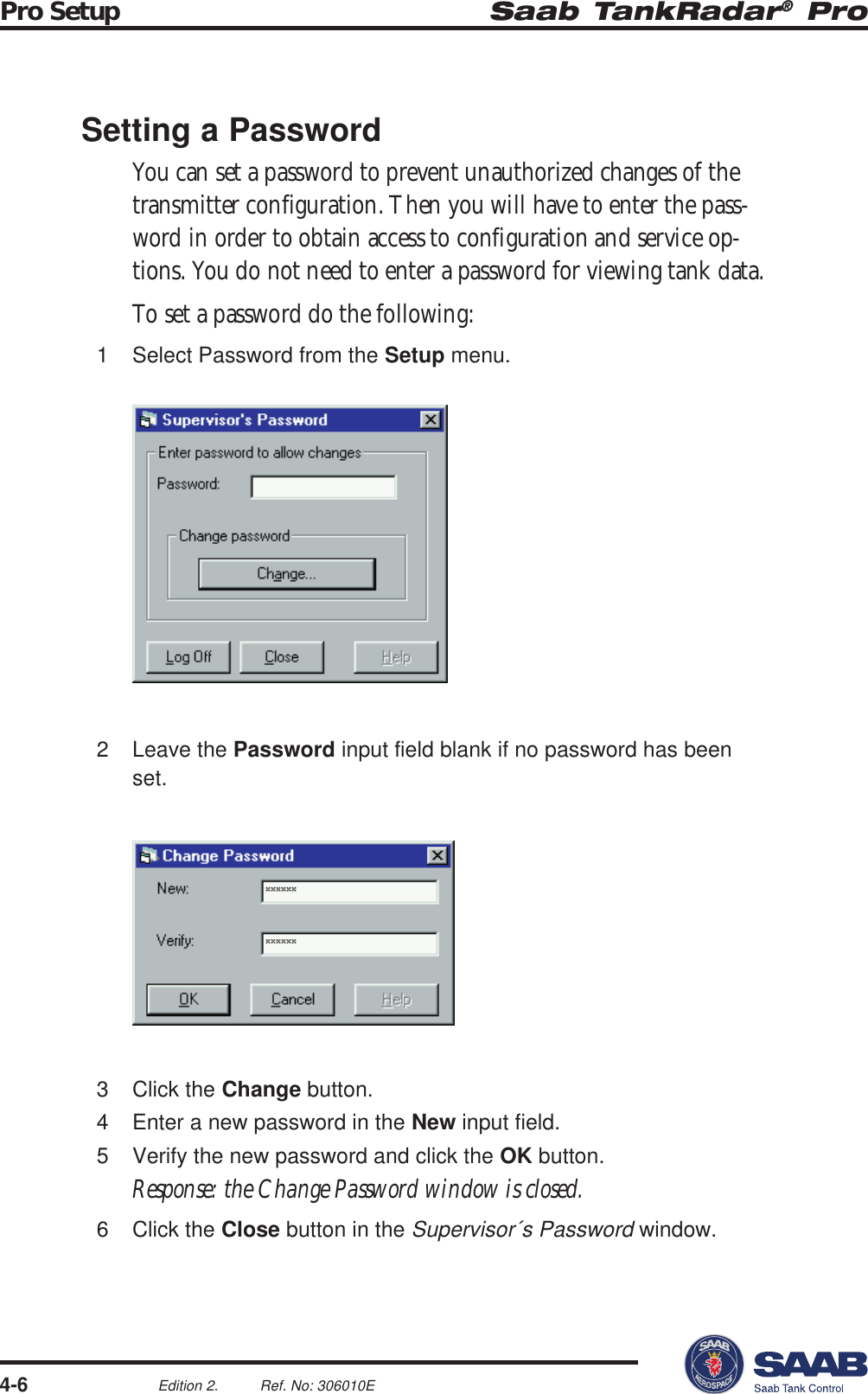
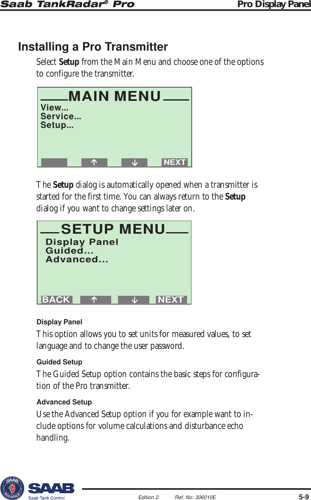
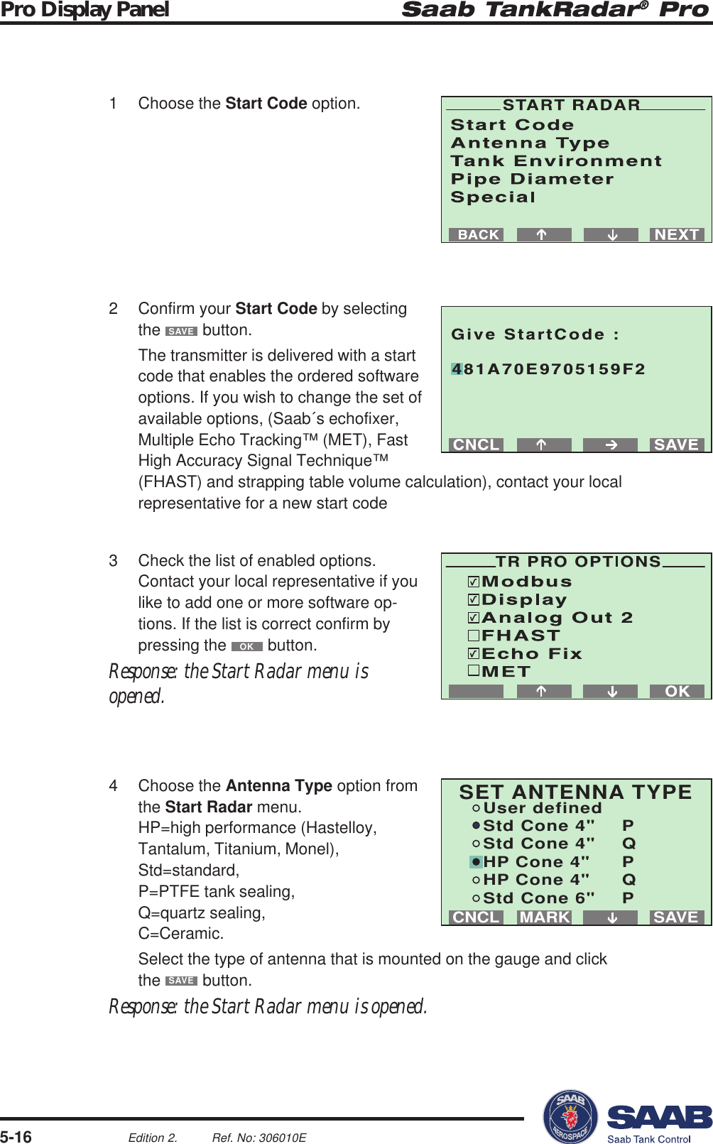

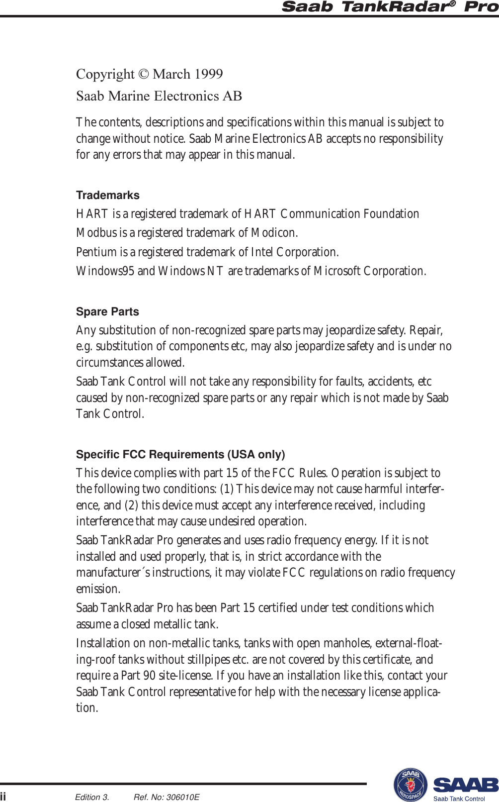
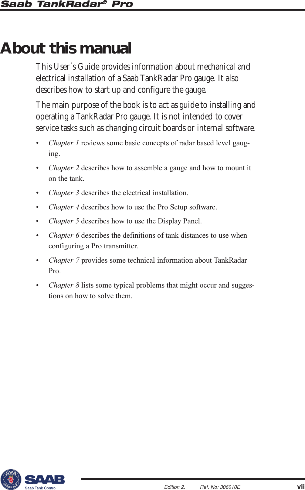
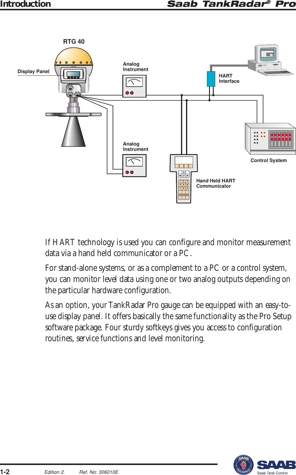
![Saab TankRadar® Pro Technical Information7-1Edition 2. Ref. No: 306010E7 Technical InformationTechnical DataPower supply 100-240 VAC or 24-48 VDCPower consumption Maximum 15 WOutput cabling Twisted and shielded pair, min. 0.5 mm2Cable glands EExe approved (CENELEC)Tank temperature -40-400 °C (-40-750 °F)Ambient temperature -40-70 °C (-40-158 °F)Standard measuring range 0-50 m (0-165 ft)Instrument accuracy ± 5 mm (±0.2”)Repeatability ±1 mm (±0.04”)Processors Dual processor design. 32-bit DSP, 50MflopsSignal processing FFT, FHASTOptional disturbance Saab´s Echofixer andecho handling Multiple Echo TrackingLevel output Display panel, analog 4-20 mA signal withdigital HART, serial Saab TRL/2 BusEx approval Transmitter Head CENELEC:(Standard and Gold versions) EEx de [ib] IIC T6.FM:Explosion proof Class I, Div. I & 2, GroupsA, B, C and D.](https://usermanual.wiki/Rosemount-Tank-Radar/PROX/User-Guide-24322-Page-110.png)
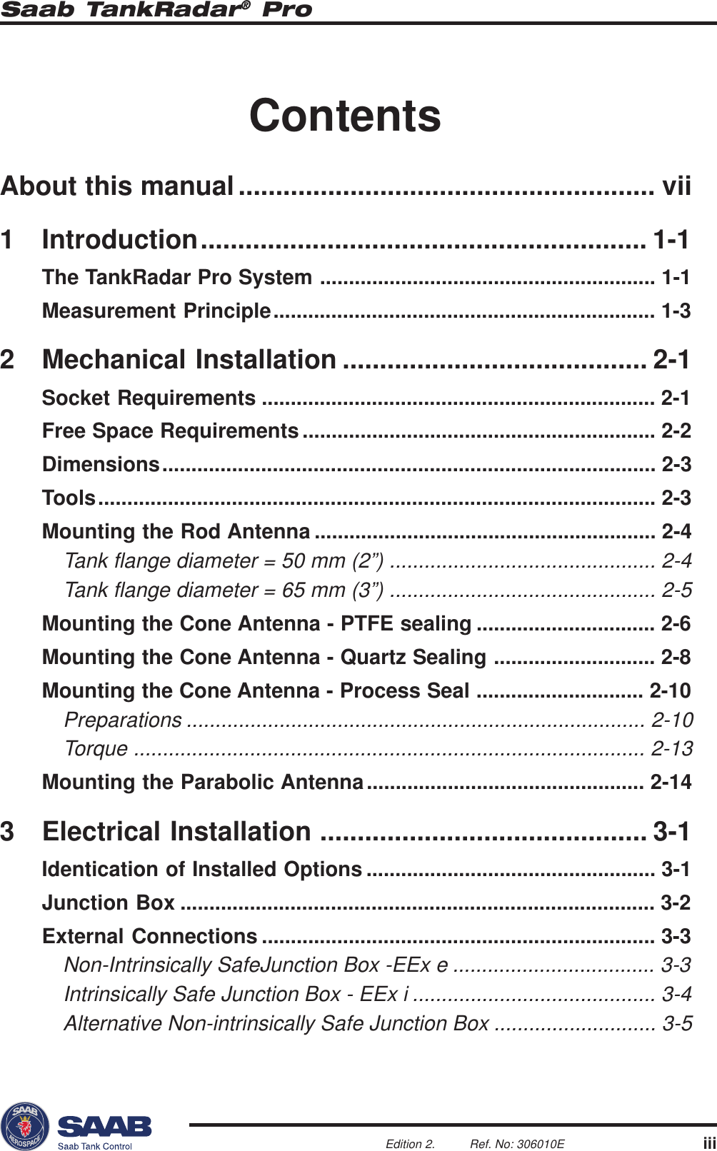
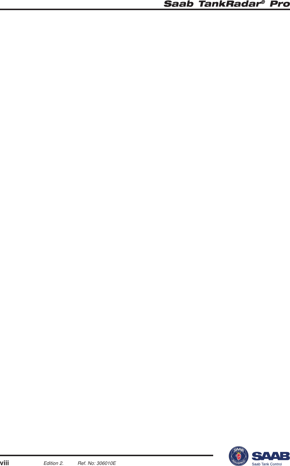
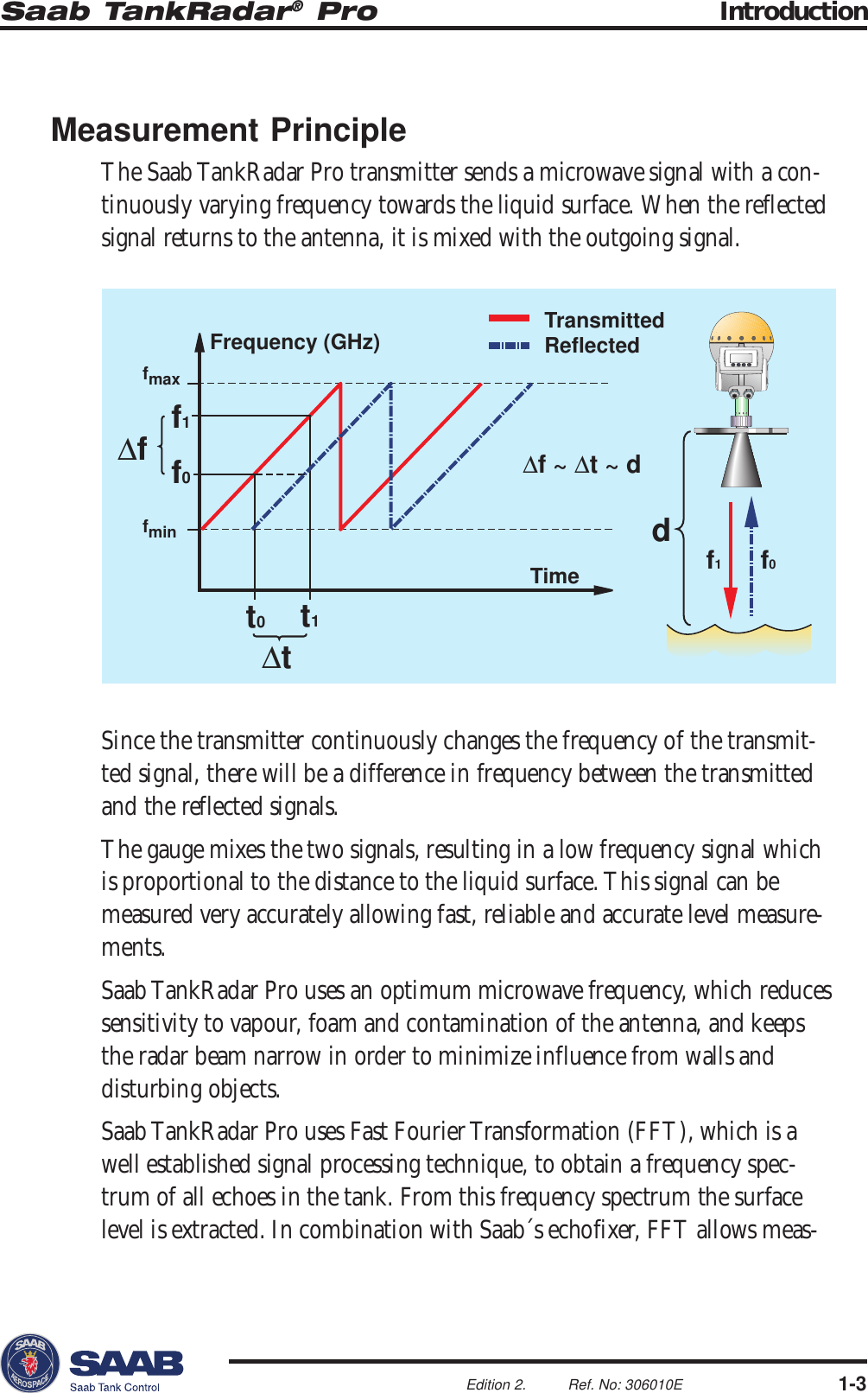
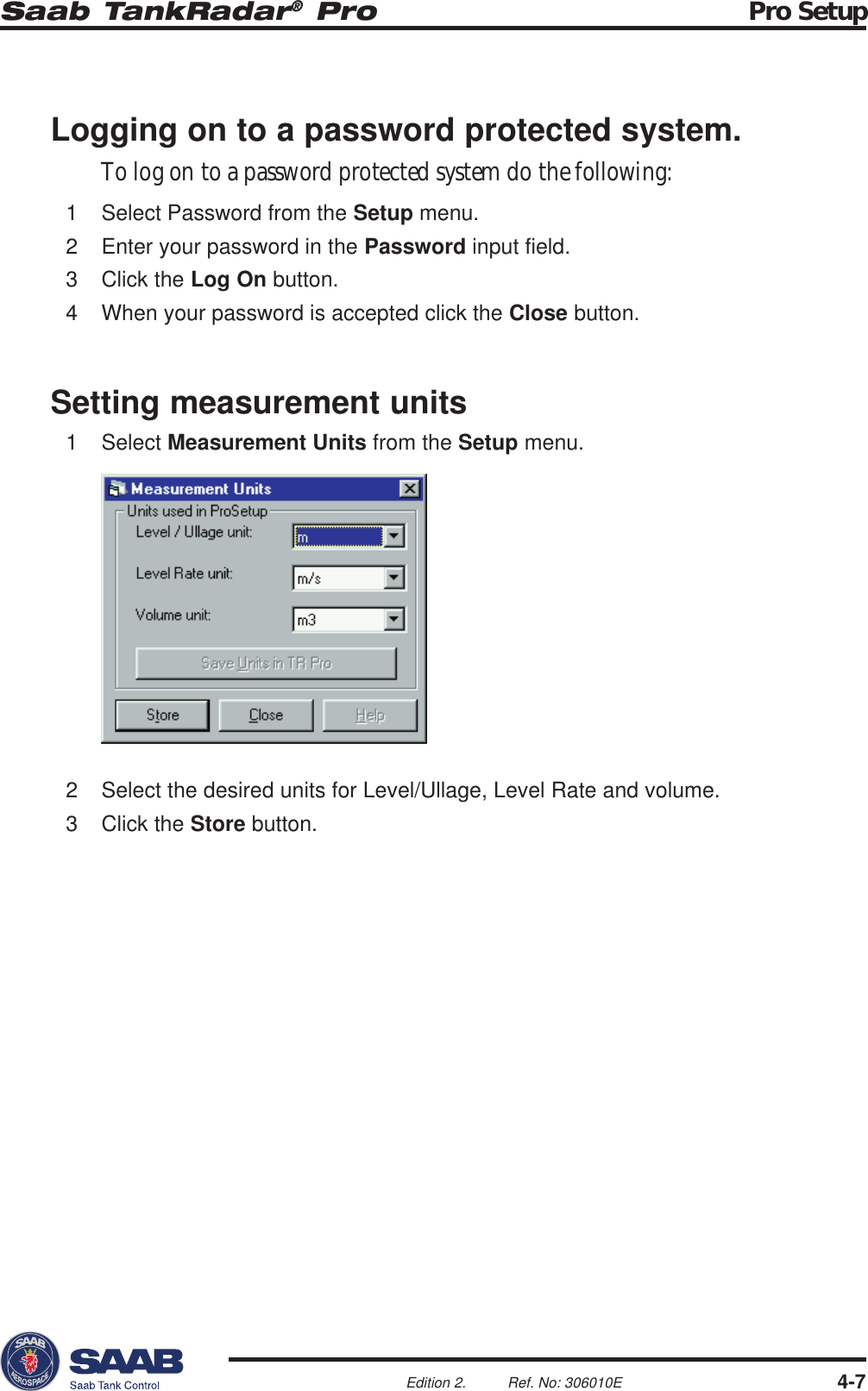
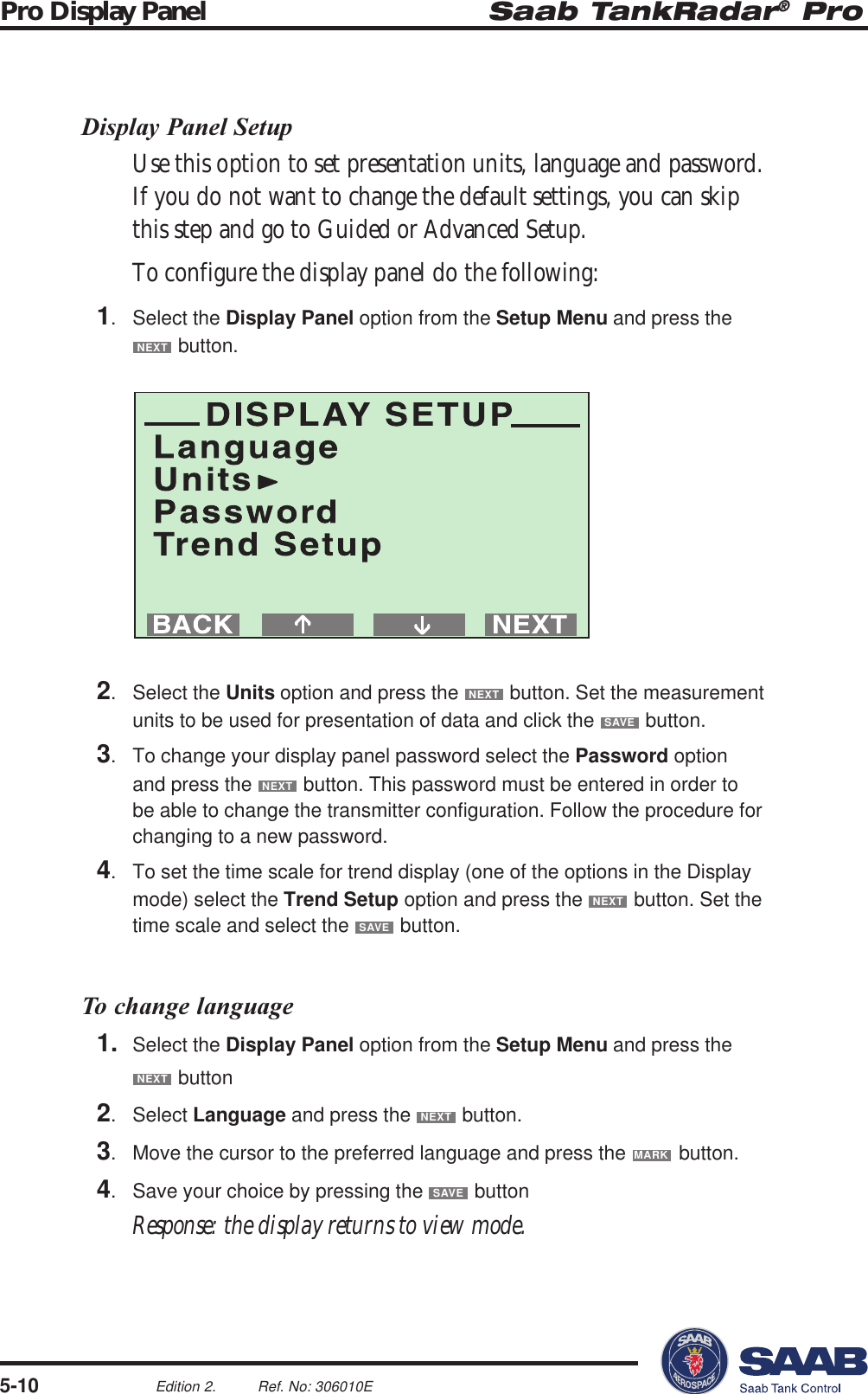
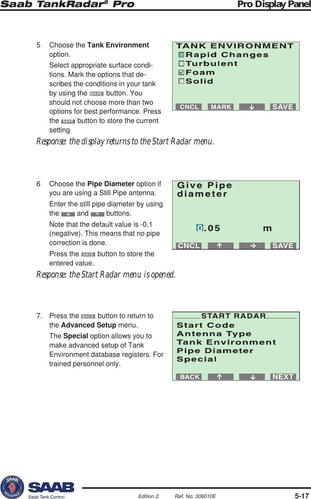
![Saab TankRadar® ProTechnical Information7-2Edition 2. Ref. No: 306010EEx approval Transmitter Head CENELEC:including Display Panel EEx de [ib] ib IIC T4FM:Explosion proof/ IS Class I, Div. I & 2,Groups A, B, C and DPressure -1 to 20 Bar (Vacuum to 300 Psi)Antennas Rod, Cone, Process Seal and ParabolaAntenna materials Teflon®, SS 316L/HC4/Tantalum, Viton/Kalrez®Dimensions 545 (H) x 200 (W) mm (4” cone)Weight 8 kgHeight above flange 400 mm (15”)Water protection IP 65Serial communication HART or Saab TRL/2 Bus](https://usermanual.wiki/Rosemount-Tank-Radar/PROX/User-Guide-24322-Page-111.png)