Rosemount Tank Radar PROX Radar Level Gauge User Manual Cover Front
Rosemount Tank Radar AB Radar Level Gauge Cover Front
Users guide

User´s Guide

i
Edition 2. Ref. No: 306010E
Saab TankRadar® Pro
User´s Guide
Second edition
Copyright © September 1998
Saab Marine Electronics AB

Saab TankRadar® Pro
ii
Edition 3. Ref. No: 306010E
Copyright © March 1999
Saab Marine Electronics AB
The contents, descriptions and specifications within this manual is subject to
change without notice. Saab Marine Electronics AB accepts no responsibility
for any errors that may appear in this manual.
Trademarks
HART is a registered trademark of HART Communication Foundation
Modbus is a registered trademark of Modicon.
Pentium is a registered trademark of Intel Corporation.
Windows95 and Windows NT are trademarks of Microsoft Corporation.
Spare Parts
Any substitution of non-recognized spare parts may jeopardize safety. Repair,
e.g. substitution of components etc, may also jeopardize safety and is under no
circumstances allowed.
Saab Tank Control will not take any responsibility for faults, accidents, etc
caused by non-recognized spare parts or any repair which is not made by Saab
Tank Control.
Specific FCC Requirements (USA only)
This device complies with part 15 of the FCC Rules. Operation is subject to
the following two conditions: (1) This device may not cause harmful interfer-
ence, and (2) this device must accept any interference received, including
interference that may cause undesired operation.
Saab TankRadar Pro generates and uses radio frequency energy. If it is not
installed and used properly, that is, in strict accordance with the
manufacturer´s instructions, it may violate FCC regulations on radio frequency
emission.
Saab TankRadar Pro has been Part 15 certified under test conditions which
assume a closed metallic tank.
Installation on non-metallic tanks, tanks with open manholes, external-float-
ing-roof tanks without stillpipes etc. are not covered by this certificate, and
require a Part 90 site-license. If you have an installation like this, contact your
Saab Tank Control representative for help with the necessary license applica-
tion.

Saab TankRadar® Pro
iii
Edition 2. Ref. No: 306010E
Contents
About this manual........................................................ vii
1 Introduction............................................................ 1-1
The TankRadar Pro System .......................................................... 1-1
Measurement Principle.................................................................. 1-3
2 Mechanical Installation ......................................... 2-1
Socket Requirements .................................................................... 2-1
Free Space Requirements ............................................................. 2-2
Dimensions..................................................................................... 2-3
Tools................................................................................................ 2-3
Mounting the Rod Antenna ........................................................... 2-4
Tank flange diameter = 50 mm (2”) .............................................. 2-4
Tank flange diameter = 65 mm (3”) .............................................. 2-5
Mounting the Cone Antenna - PTFE sealing ............................... 2-6
Mounting the Cone Antenna - Quartz Sealing ............................ 2-8
Mounting the Cone Antenna - Process Seal ............................. 2-10
Preparations ............................................................................... 2-10
Torque ........................................................................................ 2-13
Mounting the Parabolic Antenna................................................ 2-14
3 Electrical Installation ............................................ 3-1
Identication of Installed Options .................................................. 3-1
Junction Box .................................................................................. 3-2
External Connections .................................................................... 3-3
Non-Intrinsically SafeJunction Box -EEx e ................................... 3-3
Intrinsically Safe Junction Box - EEx i .......................................... 3-4
Alternative Non-intrinsically Safe Junction Box ............................ 3-5

Saab TankRadar® Pro
iv
Edition 2. Ref. No: 306010E
Connecting to a TRL2 Bus Interface ............................................ 3-6
Connecting HART devices ............................................................ 3-7
Active output (internal loop supply) .............................................. 3-7
Passive output (external loop supply)........................................... 3-7
Intrinsically safe conditions........................................................... 3-8
Non-Intrinsically safe conditions ................................................... 3-8
Connecting the Display Panel ...................................................... 3-9
Cables ........................................................................................... 3-10
Safety ............................................................................................ 3-10
Power Supply ............................................................................... 3-10
Grounding .................................................................................... 3-10
CENELEC .................................................................................. 3-10
FM .............................................................................................. 3-10
System Overview ......................................................................... 3-11
Display Panel ..............................................................................3-11
Analog Outputs............................................................................3-11
Digital Communication.................................................................3-11
Power Supply ..............................................................................3-11
Internal Connections ................................................................... 3-12
Power Supply ............................................................................. 3-12
Display Panel ............................................................................. 3-12
Primary Output ........................................................................... 3-13
Secondary Output ...................................................................... 3-14
4 Pro Setup Software ............................................... 4-1
System Requirements ................................................................... 4-2
Installing the Pro setup software ................................................. 4-2
Starting the Pro Setup Program ................................................... 4-5
Setting a Password........................................................................ 4-6
Logging on to a password protected system. ............................ 4-7

Saab TankRadar® Pro
v
Edition 2. Ref. No: 306010E
Setting measurement units........................................................... 4-7
Installing a Pro Transmitter .......................................................... 4-8
Setting a general amplitude threshold ........................................ 4-26
Creating a customized noise threshold table.............................. 4-26
Registration of False Echoes ..................................................... 4-29
Viewing Level Data ...................................................................... 4-33
Service .......................................................................................... 4-34
5 Using the Pro Display Panel................................. 5-1
Operation ........................................................................................ 5-1
Entering a Password .................................................................... 5-2
Adjusting the LCD contrast........................................................... 5-2
Softkeys........................................................................................ 5-3
Presentation of measured data .................................................... 5-4
Selecting between different alternatives....................................... 5-5
Entering numerical values ............................................................ 5-6
Viewing Level Data ........................................................................ 5-7
The View Menu ............................................................................ 5-7
Installing a Pro Transmitter .......................................................... 5-9
Display Panel Setup ................................................................... 5-10
To change language ................................................................... 5-10
Guided Setup ..............................................................................5-11
Advanced Setup ......................................................................... 5-14
Service .......................................................................................... 5-25
6 Tank Distances ...................................................... 6-1
Definitions ...................................................................................... 6-1
Examples ........................................................................................ 6-3
7 Technical Information ........................................... 7-1
Technical Data ................................................................................ 7-1

Saab TankRadar® Pro
vi
Edition 2. Ref. No: 306010E
Display Panel.................................................................................. 7-3
Analog Outputs .............................................................................. 7-3
8 Troubleshooting .................................................... 8-1
Display Panel Error Messages...................................................... 8-2
User Input Errors .......................................................................... 8-2
Internal Software Errors ............................................................... 8-2

Saab TankRadar® Pro
vii
Edition 2. Ref. No: 306010E
About this manual
This User´s Guide provides information about mechanical and
electrical installation of a Saab TankRadar Pro gauge. It also
describes how to start up and configure the gauge.
The main purpose of the book is to act as guide to installing and
operating a TankRadar Pro gauge. It is not intended to cover
service tasks such as changing circuit boards or internal software.
Chapter 1 reviews some basic concepts of radar based level gaug-
ing.
Chapter 2 describes how to assemble a gauge and how to mount it
on the tank.
Chapter 3 describes the electrical installation.
Chapter 4 describes how to use the Pro Setup software.
Chapter 5 describes how to use the Display Panel.
Chapter 6 describes the definitions of tank distances to use when
configuring a Pro transmitter.
Chapter 7 provides some technical information about TankRadar
Pro.
Chapter 8 lists some typical problems that might occur and sugges-
tions on how to solve them.

Saab TankRadar® Pro
viii
Edition 2. Ref. No: 306010E
Saab TankRadar® Pro Introduction
1-1
Edition 2. Ref. No: 306010E
1 Introduction
Saab TankRadar Pro is a powerful radar level gauge suitable for non-contact
level measurements in process tanks, storage tanks and other types of tanks.
It is designed for easy installation and maintenance free operation.
The modular hardware and software design makes it possible to specify a
TankRadar Pro gauge that will meet your requirements now and in the
future.
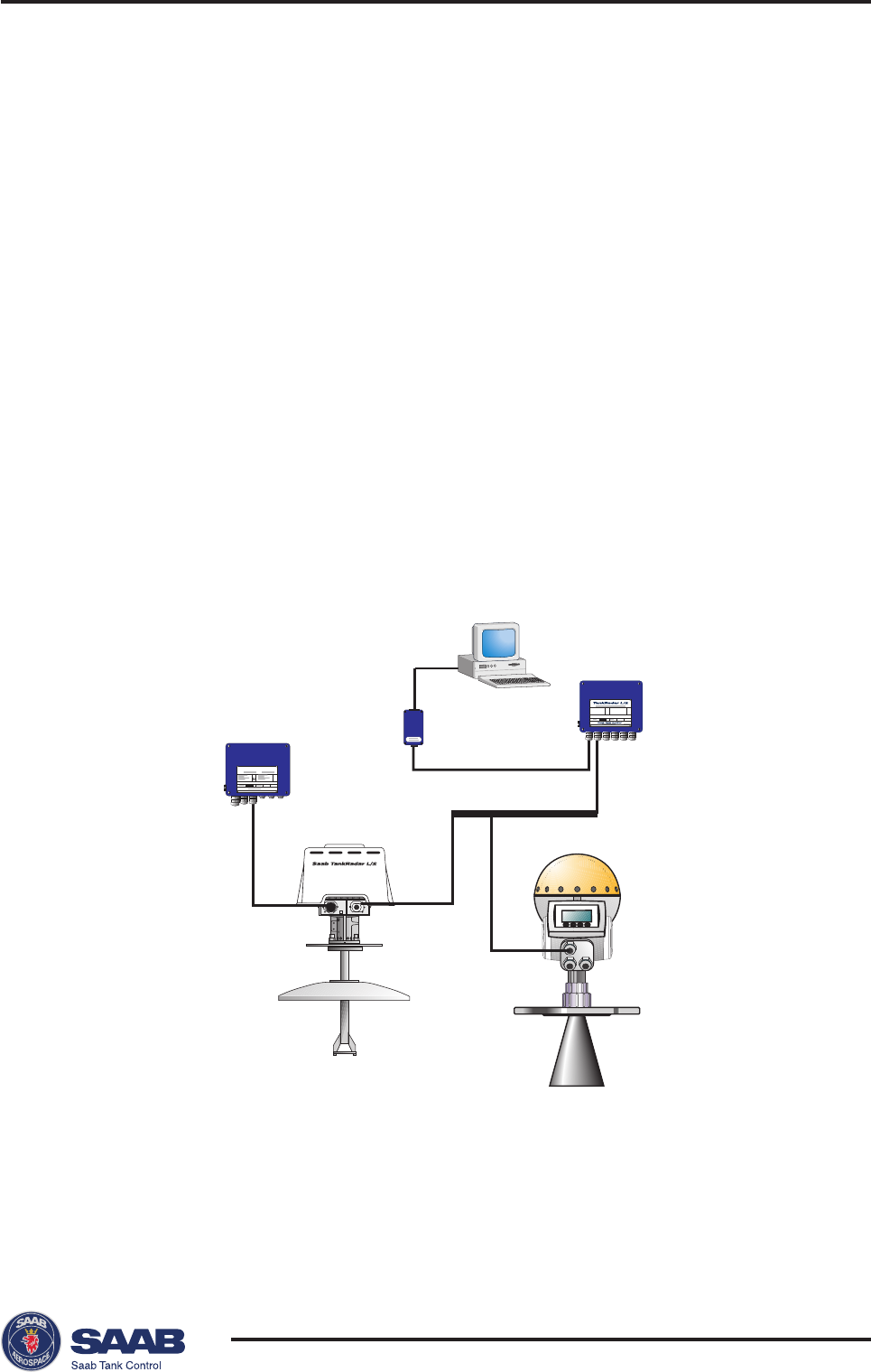
The TankRadar Pro System
The TankRadar Pro gauge offers a high degree of flexibility. It can be used
as a stand-alone unit, or it can be connected to various control systems.
You can integrate TankRadar Pro in your own Local Area Network (LAN).
By using the Saab TRL/2 Bus interface you can easily connect Pro gauges
to a Saab TankRadar L/2 system.
A specially designed software package, Pro Setup, offers configuration and
service capabilities. It also includes functions for presentation of measure-
ment data.
TankRadar L/2
Data Acquisition Unit
Field Communication
Unit
RTG 40
RTG 2930
Field Bus
Modem
Saab TankRadar® ProIntroduction
1-2
Edition 2. Ref. No: 306010E
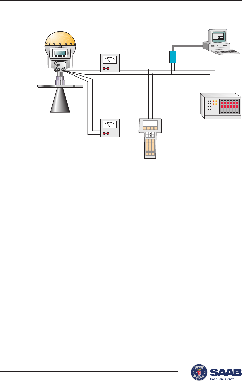
If HART technology is used you can configure and monitor measurement
data via a hand held communicator or a PC.
For stand-alone systems, or as a complement to a PC or a control system,
you can monitor level data using one or two analog outputs depending on
the particular hardware configuration.
As an option, your TankRadar Pro gauge can be equipped with an easy-to-
use display panel. It offers basically the same functionality as the Pro Setup
software package. Four sturdy softkeys gives you access to configuration
routines, service functions and level monitoring.
123
456
789
Display Panel
RTG 40
Analog
Instrument
Analog
Instrument
Hand Held HART
Communicator
Control System
HART
Interface
Saab TankRadar® Pro Introduction
1-3
Edition 2. Ref. No: 306010E
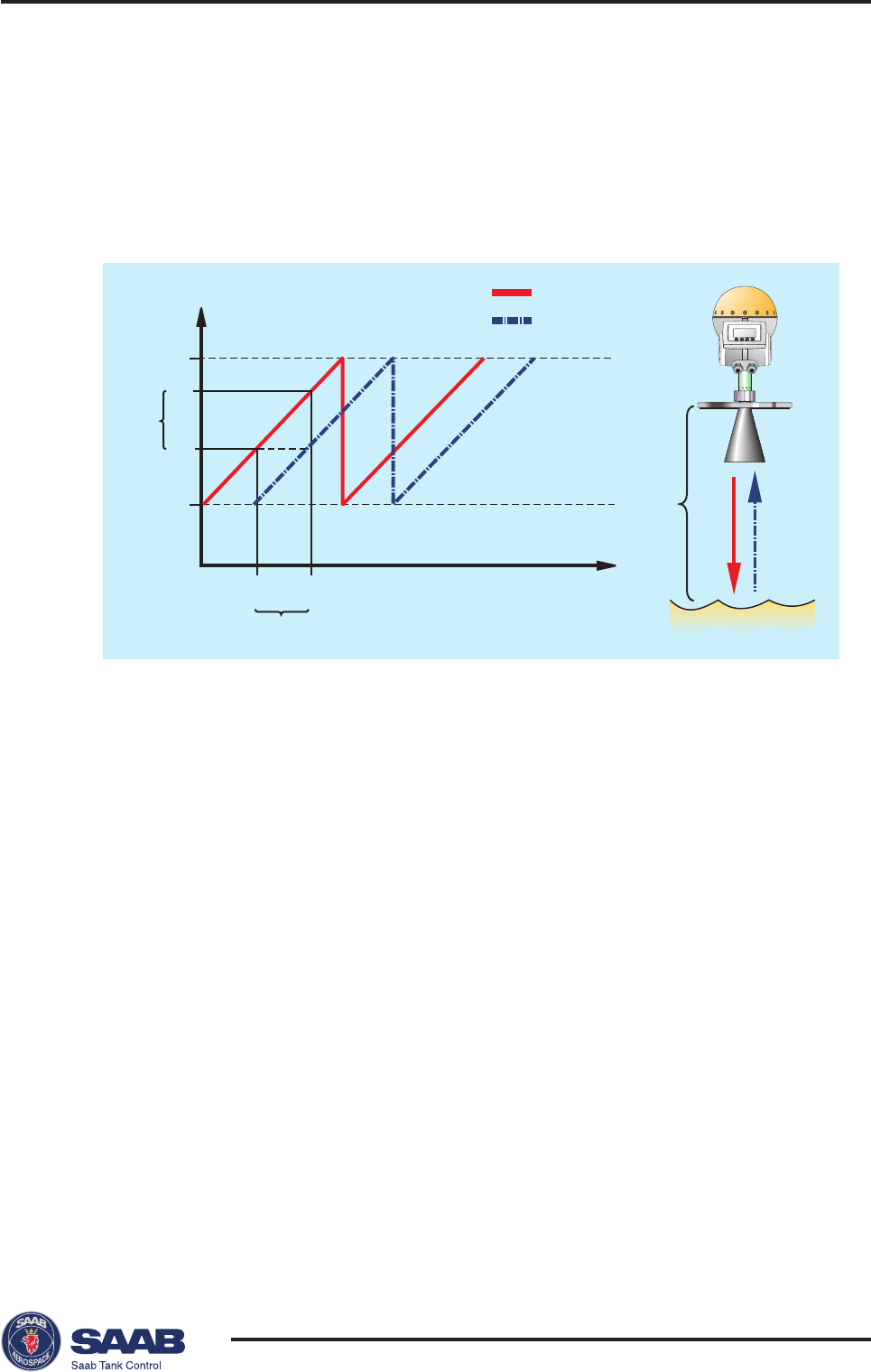
Measurement Principle
The Saab TankRadar Pro transmitter sends a microwave signal with a con-
tinuously varying frequency towards the liquid surface. When the reflected
signal returns to the antenna, it is mixed with the outgoing signal.
Since the transmitter continuously changes the frequency of the transmit-
ted signal, there will be a difference in frequency between the transmitted
and the reflected signals.
The gauge mixes the two signals, resulting in a low frequency signal which
is proportional to the distance to the liquid surface. This signal can be
measured very accurately allowing fast, reliable and accurate level measure-
ments.
Saab TankRadar Pro uses an optimum microwave frequency, which reduces
sensitivity to vapour, foam and contamination of the antenna, and keeps
the radar beam narrow in order to minimize influence from walls and
disturbing objects.
Saab TankRadar Pro uses Fast Fourier Transformation (FFT), which is a
well established signal processing technique, to obtain a frequency spec-
trum of all echoes in the tank. From this frequency spectrum the surface
level is extracted. In combination with Saab´s echofixer, FFT allows meas-
f
max
Frequency (GHz)
Time
∆ff
1
∆f ~ ∆t ~ d
t
0
∆t
f
min
f
0
t
1
Transmitted
Reflected
df0f1

Saab TankRadar® ProIntroduction
1-4
Edition 2. Ref. No: 306010E
urements in tanks with agitators, mixers and other disturbing objects.
Saab´s echofixer provides a technique to adapt measurements to various
situations, by using information from previous measurements.
To further improve measurement accuracy, Saab TankRadar Pro can utilize
the benefits of Saab´s Fast High Accuracy Signal Technique™
(FHAST™).
Multiple Echo Tracking™ (MET™) is another advanced Saab TankRadar
Pro feature, which provides increased resolution in tanks with disturbing
objects. MET™ facilitates the separation of disturbances from the actual
product surface echo.
Saab TankRadar® Pro Mechanical Installation
2-1
Edition 2. Ref. No: 306010E
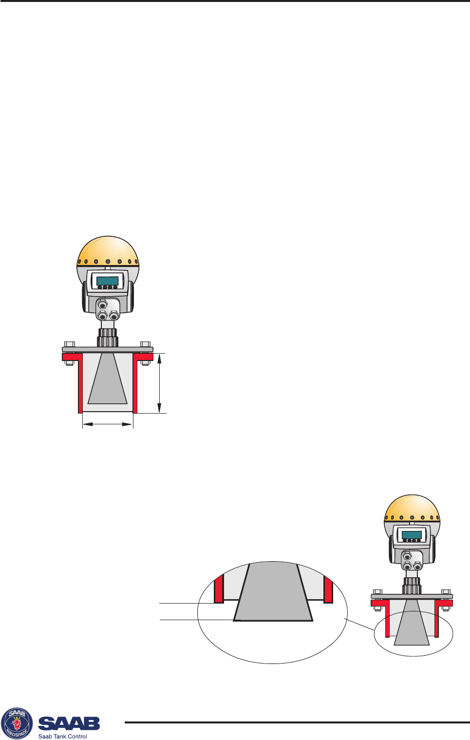
Lmax (mm): 300 (4” cone antenna)
410 (6” cone antenna)
525 (8” cone antenna)
600 (parabolic antenna)
150 (rod antenna)
300 (Process Seal antenna)
Ømin (mm): 98 (4” cone antenna)
146 (6” cone antenna)
194 (8” cone antenna)
500 (parabolic antenna)
50/60 (rod antenna)
100 (4” Process Seal antenna)
150 (6” Process Seal antenna)
2 Mechanical Installation
For optimum measurement performance the TR Pro gauge
should be mounted according to the socket requirements and
the free space requirements illustrated below.
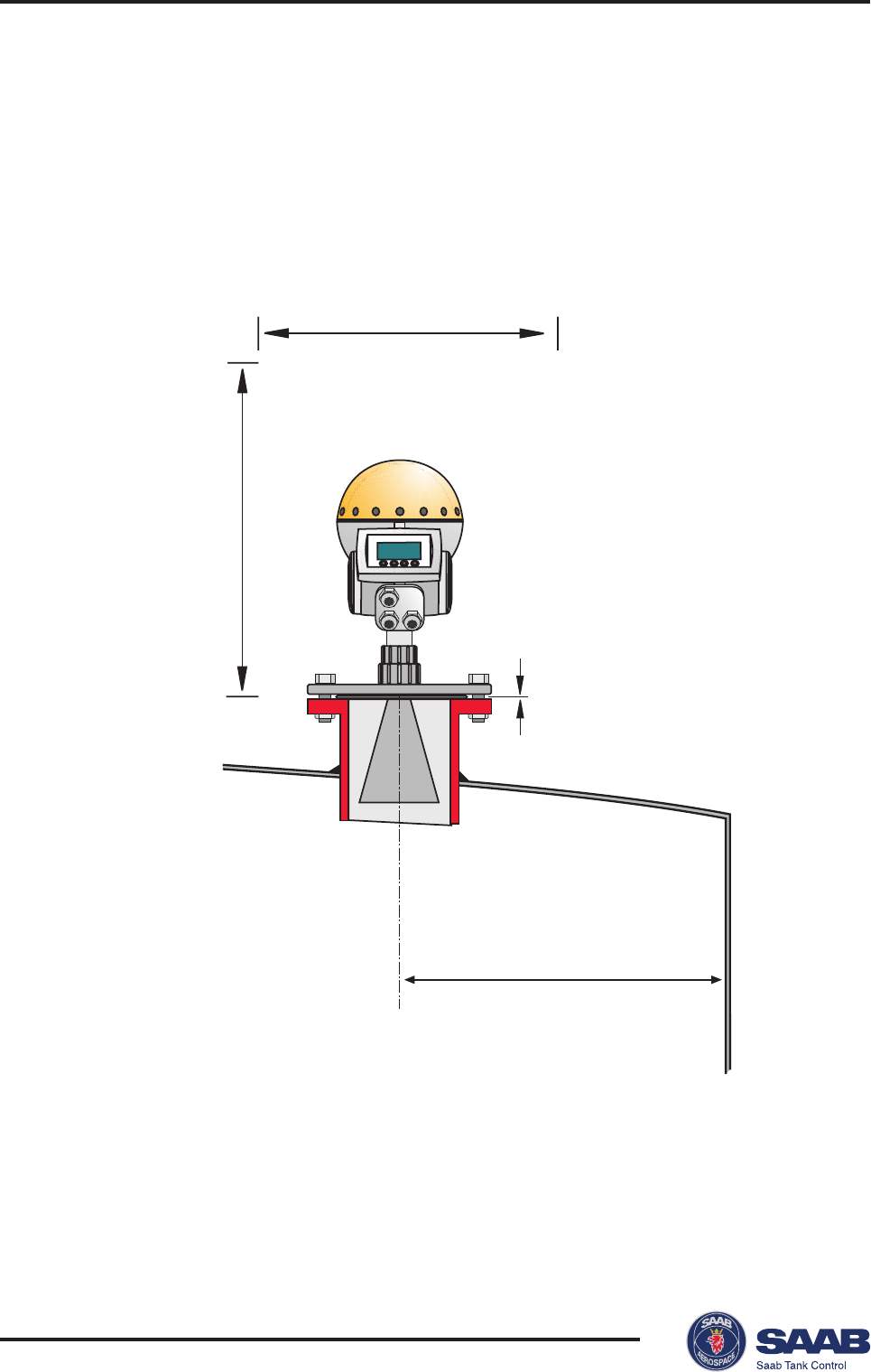
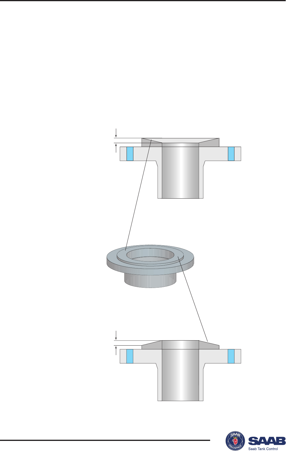
Socket Requirements
In order to allow the microwaves to propagate freely, the socket
dimensions should be kept within the specified limits for differ-
ent antenna sizes.
For best measurement
performance we recom-
mend that the nozzle is
shorter than the antenna.
Saab TankRadar® ProMechanical Installation
2-2
Edition 2. Ref. No: 306010E
Service space (mm):
• Cone antenna: 650
• Rod antenna: 700
• Process Seal antenna: 800
• Parabolic antenna: 700
Maximum angle:
• Cone antenna: 1°
• Rod antenna: 3°
• Process Seal antenna: 3°
• Parabolic antenna: 0.5°
Minimum distance (m):
• Cone antenna: 0.6
• Rod antenna: 0.3
• Process Seal antenna: 0.6
• Parabolic antenna: 0.6
Service space 550 mm
Free Space Requirements
Position the gauge in a way that allows the microwaves to propa-
gate without disturbance from the tank wall, according to the
illustration below.
Saab TankRadar® Pro Mechanical Installation
2-3
Edition 2. Ref. No: 306010E
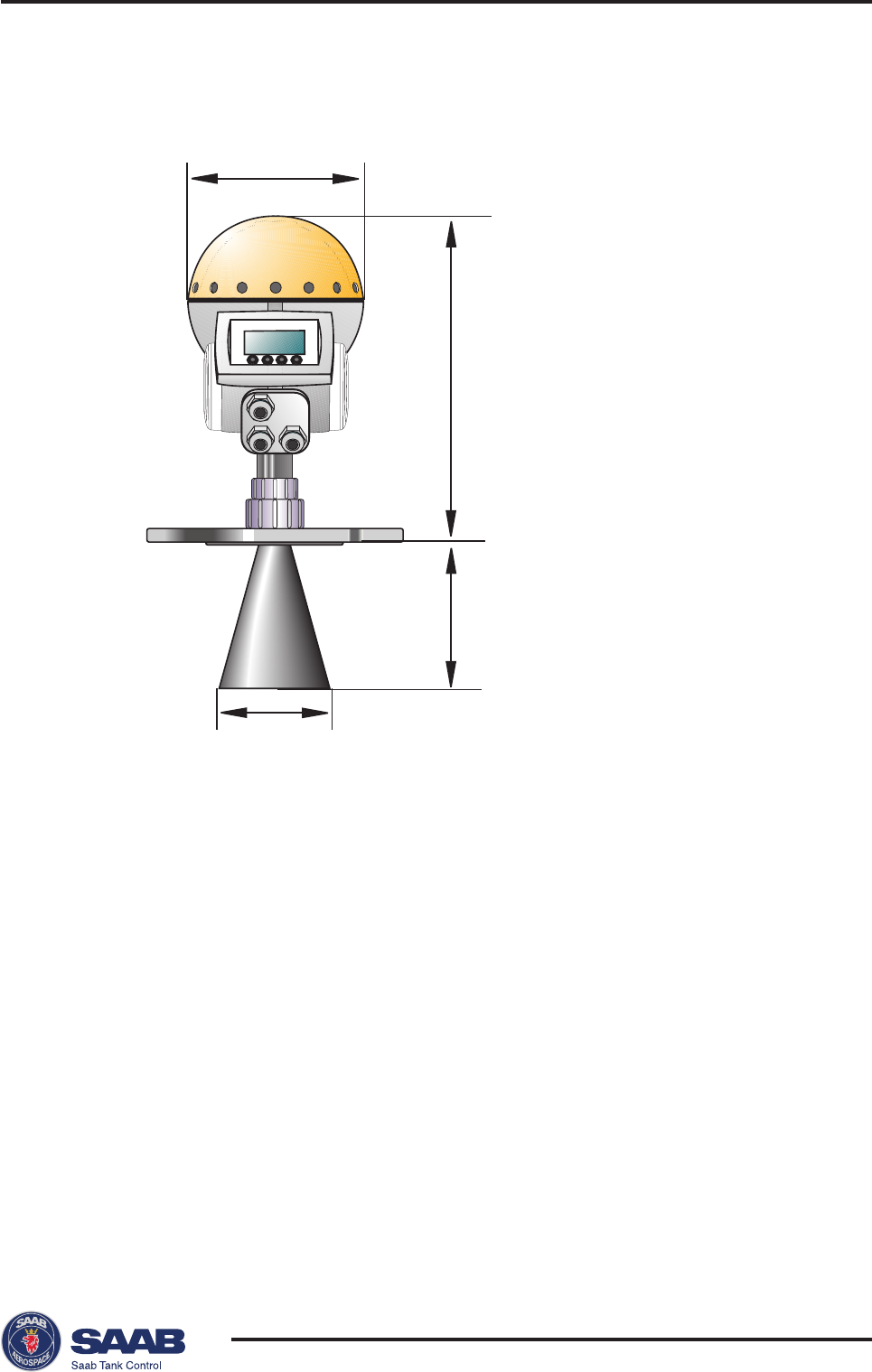
200 mm
150 mm (4” cone antenna)
260 mm (6” cone antenna)
370 mm (8” cone antenna)
395 mm
92 mm (4” cone antenna)
140 mm (6” cone antenna)
188 mm (8” cone antenna)
Dimensions
Tools
The following set of tools is needed for installation of a TankRadar Pro
gauge:
• Screw driver
• Adjustable wrench
• Dispenser for retaining rings
• Allen key
• Circlip pliers
• Pro multipurpose key
Saab TankRadar® ProMechanical Installation
2-4
Edition 2. Ref. No: 306010E
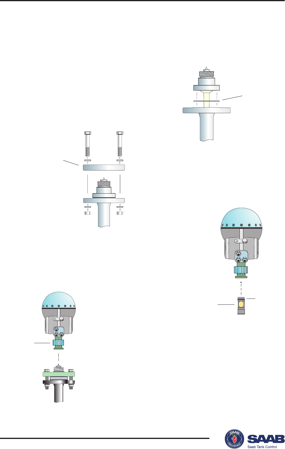
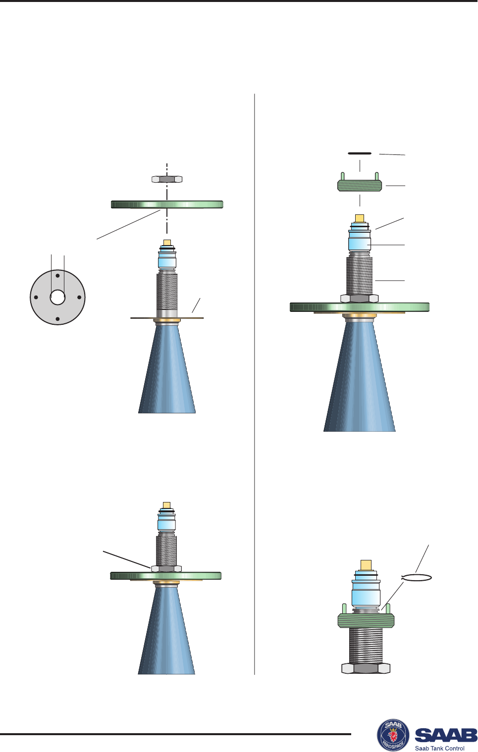
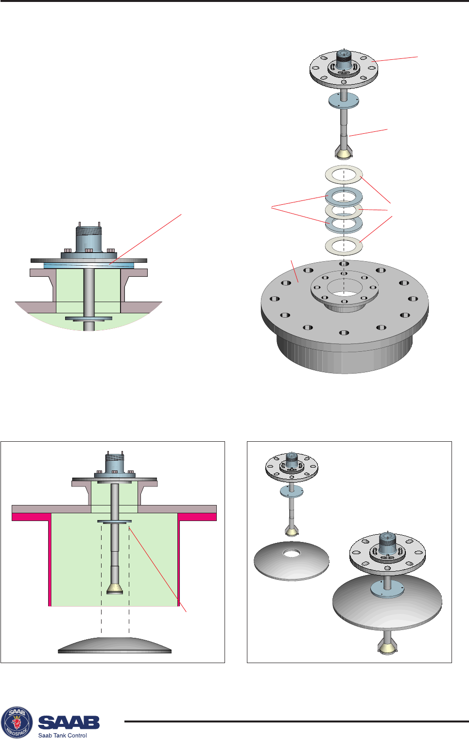
Gasket
Loose flange
Wave guide tube O-ring
Nut
Mounting the Rod Antenna
Make sure that all parts are clean and dry when mounted.
Tank flange diameter = 50 mm (2)
1. Put a gasket on the socket
and insert the antenna.
2. Mount the loose flange
and tighten the screws.
3. Insert the wave guide tube into the
upper wave guide.
Make sure that all parts are clean
and dry.
4. Place the transmitter on top of the
antenna and tighten the nut.
Saab TankRadar® Pro Mechanical Installation
2-5
Edition 2. Ref. No: 306010E
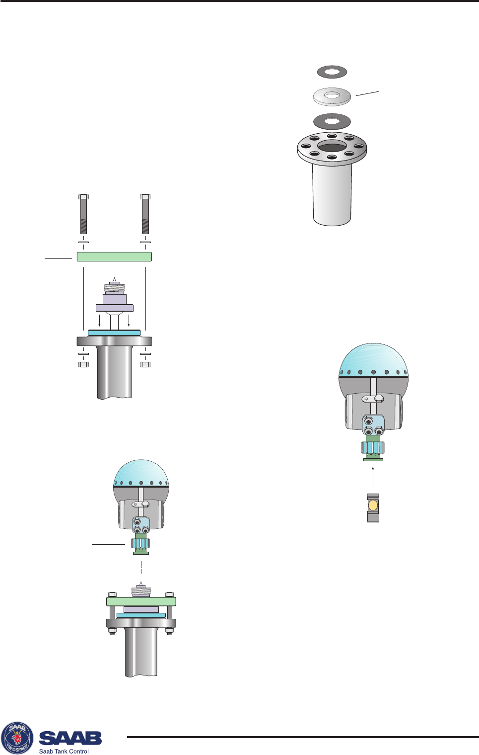
Flange adapter
Flange
Nut
Wave guide
tube
Tank flange diameter = 65 mm (3)
1. Carefully center the flange adap-
ter on top of the tank flange.
Use gaskets under and above the
flange adapter.
2. Insert the antenna into the socket.
Mount the loose flange and
tighten the screws.
3. Insert the wave
guide tube into
the upper wave
guide.
Make sure that
all parts are
clean and dry.
4. Place the transmitter on top of the
antenna and tighten the nut.
5. Make sure that all nuts and bolts are
tightened.
Proceed with the electrical installation
as described in chapter 3.
Saab TankRadar® ProMechanical Installation
2-6
Edition 2. Ref. No: 306010E
Locking ring
Wave guide unit
Adapter
Sleeve
Locking ring
Locking nut
O-ring
Flange
Diameter=33 mm
Note!
No gasket
on top of
this plate
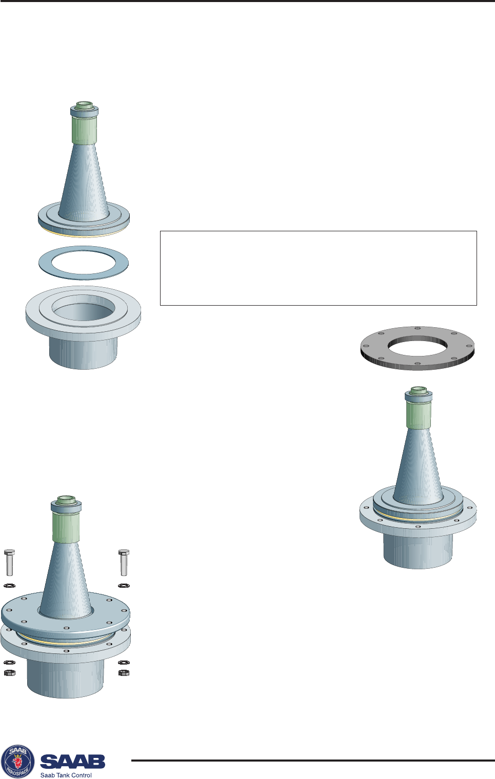
Mounting the Cone Antenna - PTFE sealing
1. Mount the flange on top of the cone
plate.
Make sure that the bottom side of
the flange is flat and all parts are
clean and dry.
2. Secure the flange with the locking
nut.
Make sure that the nut fits tightly to
the flange.
3. Mount the adapter on top of the
sleeve.
4. Secure the adapter with the locking
ring.
Saab TankRadar® Pro Mechanical Installation
2-7
Edition 2. Ref. No: 306010E
Gasket
Protection sleeve
Adapter
Guide pins
Upper wave guide
Wave guide tube
Upper wave guide
O-ring
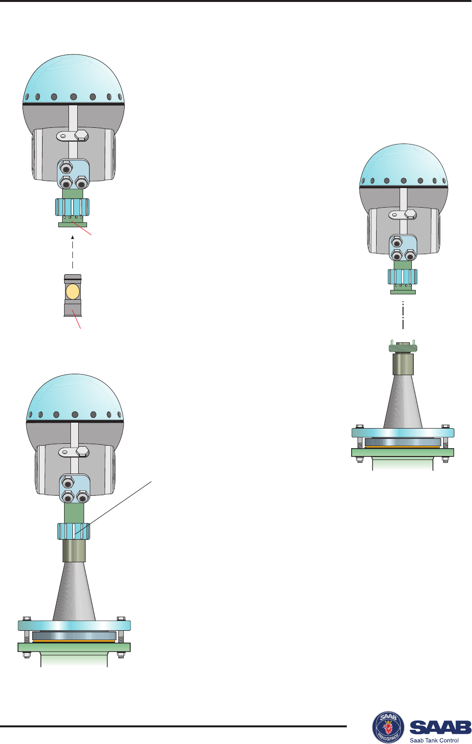
5. Carefully fit the flange and the
cone antenna on the tank
nozzle.
Tighten with screws and nuts.
6. Insert the wave guide
tube into the upper
wave guide.
Make sure that the
gasket at the lower
end of the wave
guide tube is in
place.
7. Place the protection sleeve on the
flange.
Mount the transmitter head. Check
that the guide pins on the adapter
enter the correspond-
ing grooves on the
upper wave guide.
8. Proceed with the
electrical installation.
Saab TankRadar® ProMechanical Installation
2-8
Edition 2. Ref. No: 306010E
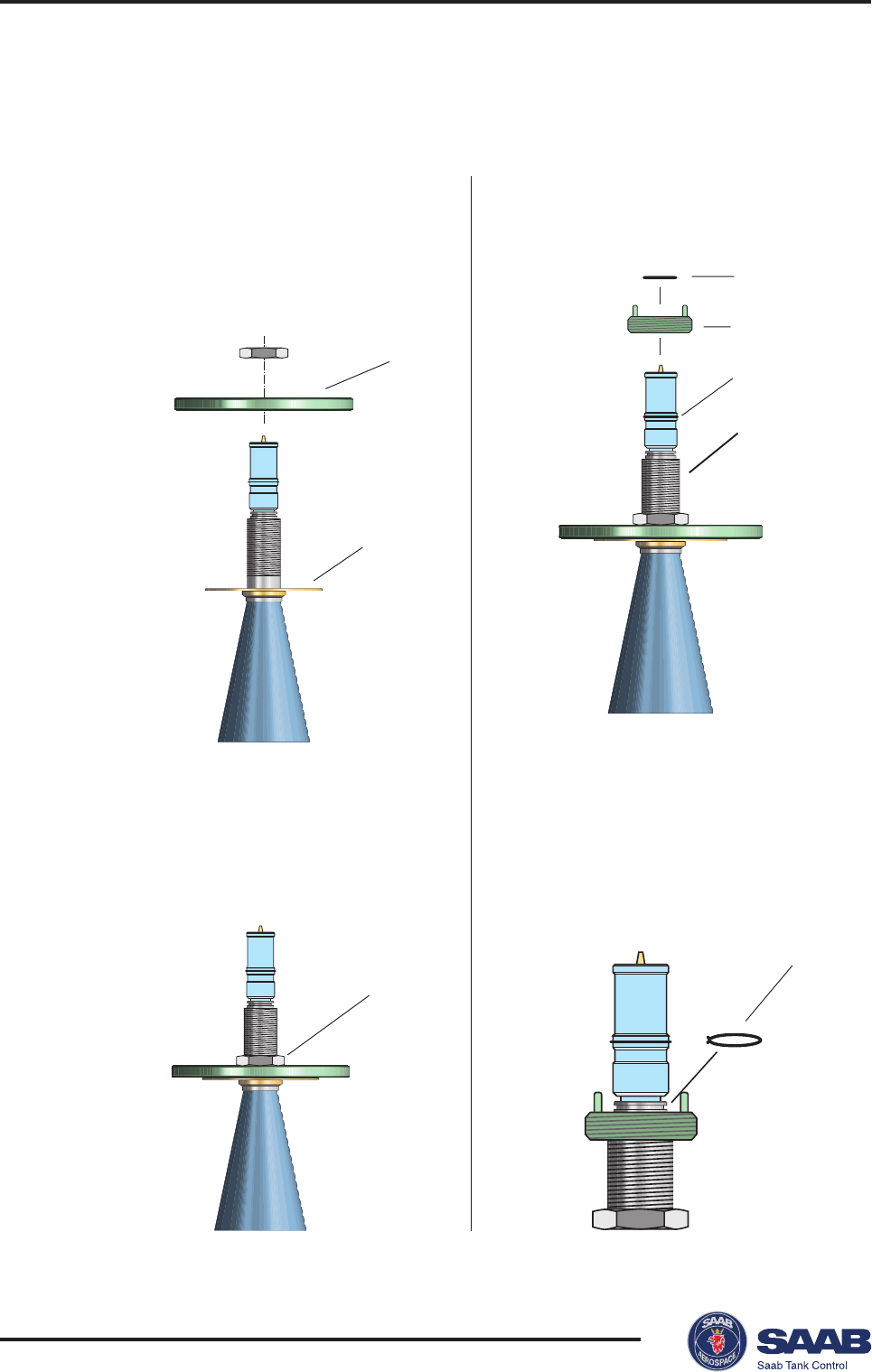
Locking nut
Locking ring
Adapter
Sleeve
Locking ring
Flange
Note!
No gasket
on top of
this plate
O-ring
Mounting the Cone Antenna - Quartz Sealing
2. Secure the flange with the locking
nut.
Make sure that the locking nut fits
tightly to the flange.
3. Mount the adapter on the sleeve.
4. Secure the adapter with the locking
ring.
1. Mount the flange on top of the cone
plate.
Make sure that the bottom side of
the flange is flat and all parts are
clean and dry.
Saab TankRadar® Pro Mechanical Installation
2-9
Edition 2. Ref. No: 306010E
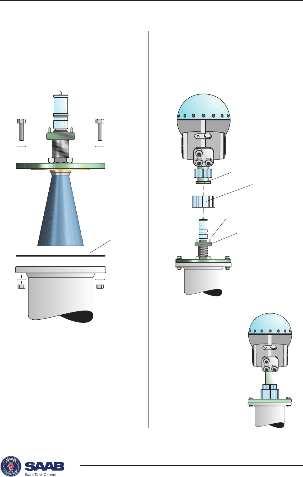
Gasket
Protection
sleeve
Upper wave guide
Guide pins
Adapter
5. Carefully fit the flange and the
cone antenna on the tank flange.
Tighten with screws and nuts.
6. Place the protection sleeve on the
flange.
Mount the transmitter head. Check
that the guide pins on the adapter
enter the corresponding grooves
on the upper wave guide.
7. Proceed with
the electrical
installation.
Saab TankRadar® ProMechanical Installation
2-10
Edition 2. Ref. No: 306010E
d
d
Convex:
Ceramic window: d<0.1 mm
PTFE window: d<0.5 mm
Concave:
Ceramic window: d<0.1 mm
PTFE window: d<0.5 mm
Mounting the Cone Antenna - Process Seal
Preparations
It is very important that the nozzle surface is flat. The maximum
deviation must be within the following specifications as illustrated
below (see Installation Instruction Process Seal Doc. no. 9240007-985):
Saab TankRadar® Pro Mechanical Installation
2-11
Edition 2. Ref. No: 306010E
To mount the antenna do the following:
2. Put the loose flange
on top of the antenna
3. Tighten the flange to
the antenna by using
screws and nuts. Use
lubricating grease to
minimize friction
when the screws are
tightened.
Note! Tighten the screws carefully to a torque
according to the recommended values in
table 1.
Tighten opposite screws in pair.
Note! Use gaskets delivered by Saab. These gaskets are
optimized for use with microwave emitting equip-
ment. No other gaskets than Saab original may be
used for Process Seal antennas!
1. Place a gasket on top of the socket and mount
the antenna.
Use one of the two gaskets delivered by Saab:
• Teflon
or
• Graphite for temperatures above 250 º C.
Saab TankRadar® ProMechanical Installation
2-12
Edition 2. Ref. No: 306010E
Nut
Wave guide tube
Wave guide
4. Insert the wave
guide tube into the
upper wave guide.
5. Mount the transmitter
head onto the adapter.
6. Tighten the nut and make sure that the
transmitter head fits tightly to the
antenna.

Saab TankRadar® Pro Mechanical Installation
2-13
Edition 2. Ref. No: 306010E
Table 1. Recommended torque for
flange screws.
)mN(euqroTdednemmoceR
EFTP
NID egnalF 6NP01NP61NP52NP04NP
001ND3211115151
051ND215151
ISNA egnalF isP051isP003
"41151
"65101
cimareC
NID egnalF 6NP01NP61NP52NP04NP
001ND9653535454
051ND636464
ISNA egnalF isP051isP003
"45354
"66413
Torque
Attach the flange screws by using the following recommended torque
values:
Saab TankRadar® ProMechanical Installation
2-14
Edition 2. Ref. No: 306010E
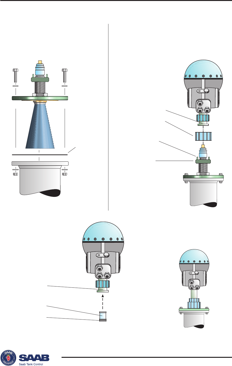
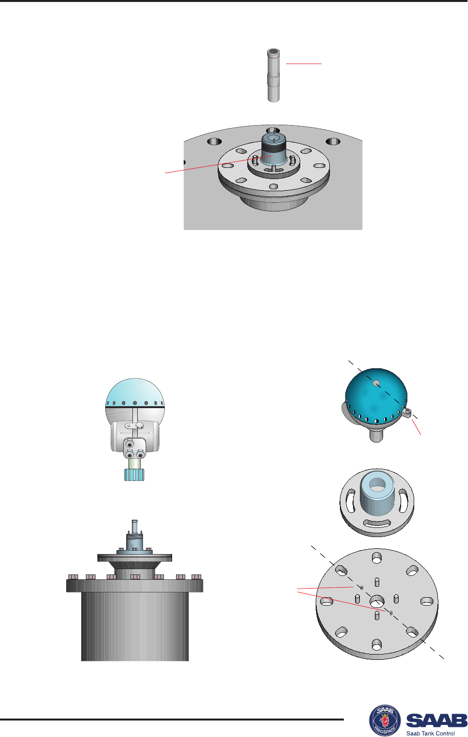
Flange
Guide pin
Antenna feeder
Hole
TRL2 adapter
Guide pin
Guide pin
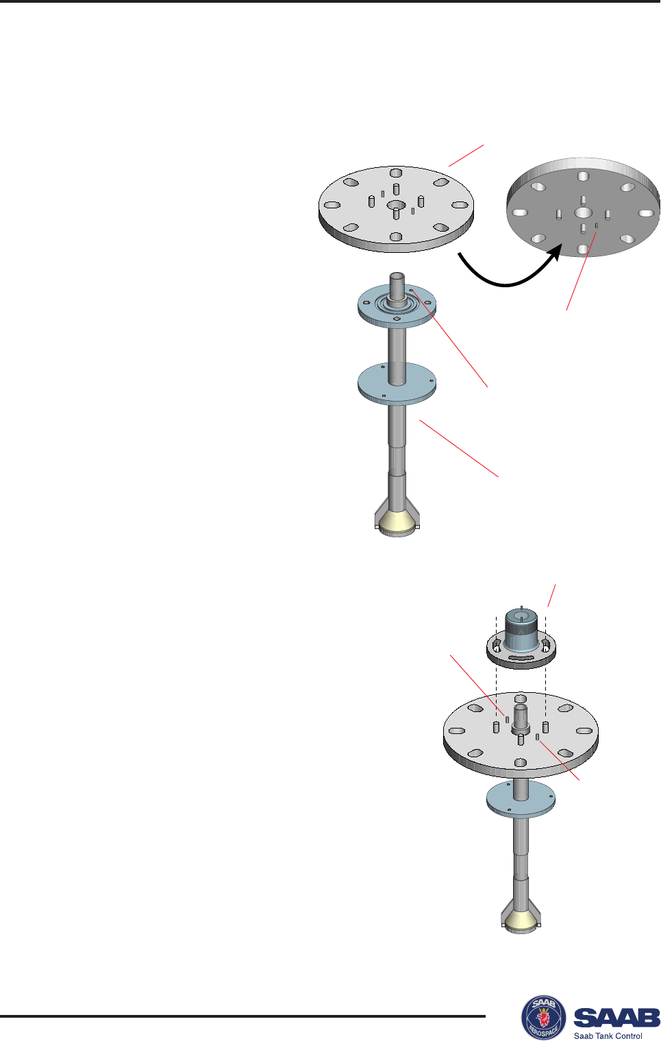
Mounting the Parabolic Antenna
1. Mount the flange on top of
the antenna feeder. Use
the screws and nuts
delivered with the unit.
Make sure that the guide
pin at the bottom side of
the flange fits into the
corresponding hole on the
feeder. See illustration.
2. Mount the TRL2 adapter on top
of the flange and tighten the nuts
loosely in order to allow the
TRL2 adapter to be rotated.
The antenna feeder will be
aligned to the transmitter head
by using the two guide pins.
Note the positions of the guide
pins by for example putting a
mark at the holes in line with the
guide pins.
Saab TankRadar® Pro Mechanical Installation
2-15
Edition 2. Ref. No: 306010E
Flange
Antenna
feeder
Gaskets
Angular rings
Nozzle
Lower
flange
Parabola
3. Mount the antenna feeder to the tank nozzle.
If necessary, use angular rings (inclination
device) to align the antenna within
±0.5o. The rings can be used if the tank
nozzle flange is horizontal within ±4o.
4. Mount the parabola onto the lower
flange on the antenna feeder.
Saab TankRadar® ProMechanical Installation
2-16
Edition 2. Ref. No: 306010E
TCP
tube
Guide pins
Cover Locking
Transmitter head
TRL2 adapter
5. Mount the TCP tube into the TRL2
adapter.
6. Mount the transmitter head.
Rotate the head and the TRL2 adapter to align the cover locking at the
back of the transmitter head with the guide pins.
Note! It is very important that the transmitter head is properly aligned to
the guide pins. Improper alignment may cause poor measurement
performance.
Saab TankRadar® Pro Electrical Installation
3-1
Edition 2. Ref. No: 306010E
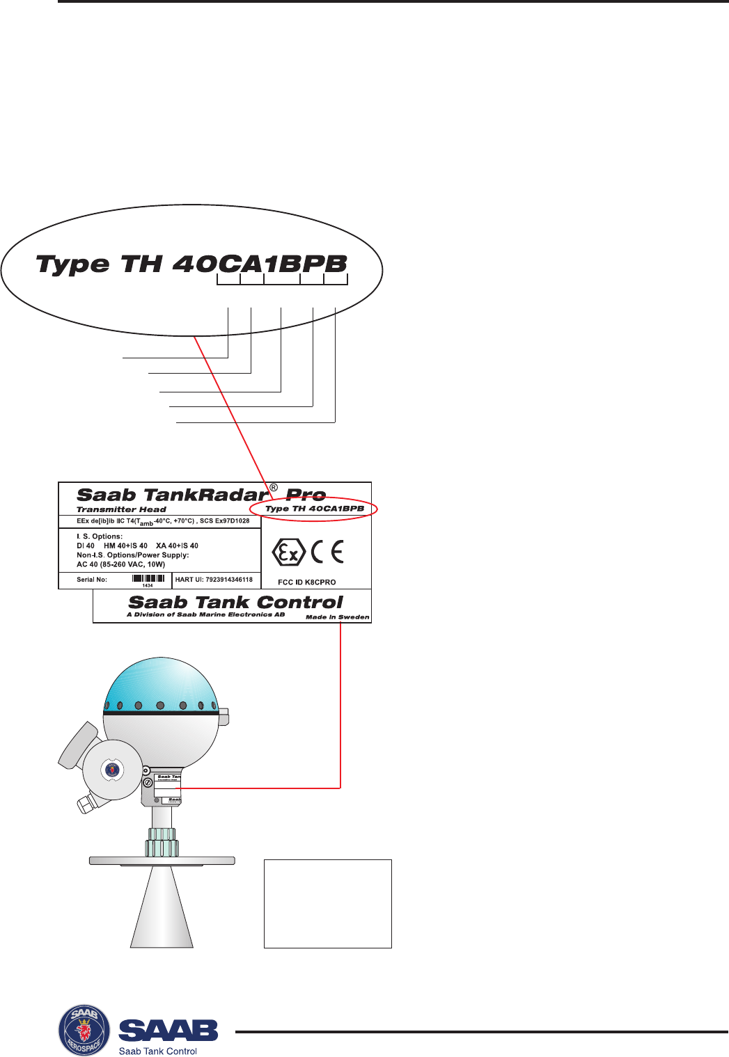
FCC ID K8CPRO
EEx de[ib]ib IIC T4(Tamb-40°C, +70°C)
I. S. Options:
DI 40 HM 40+IS 40 XA 40+IS 40
Non-I.S. Options/Power Supply:
AC 40 (85-260 VAC, 10W)
Serial No:
1434
SCS Ex97D1028
NE
P
AS
OU
V
R
IR
S
O
U
S
T
E
N
S
IO
N
.
H
AZ
A
R
D
O
U
S
A
T
M
OS
PH
E
R
E
S
DO
NO
T
O
P
EN
W
H
EN
EN
E
R
G
IZ
E
D.
T
O
P
R
E
V
EN
T
I
GN
I
TI
ON
OF
I II III IV V
Approval
Power Supply
Primary Output
Display Panel
Secondary Output
3 Electrical Installation
Identication of
Installed Options
I Approval
C Cenelec
FFM
P PTB
X Other certificates
II Power Supply
A 100 - 240 VAC nominal power
D 24 -48 VDC nominal power
III Primary Output
1A Non-IS HART/4-20 mA,
active.
1C Non-IS HART/4-20 mA,
passive.
1B IS HART/4-20 mA,
active.
1D IS HART/4-20 mA,
passive.
2A TRL2 Bus
IV Display Panel
0 No display panel
P Display panel
V Secondary Output
0 No secondary output
A Non-intrinsically safe 4-20 mA,
active.
B Intrinsically safe 4-20 mA,
active.
C Non-intrinsically safe 4-20 mA,
passive.
D Intrinsically safe 4-20 mA,
passive.
Note! If you change
optional circuit boards
the label must be
exchanged to show the
current inputs and
outputs.
3-2
Edition 2. Ref. No: 306010E
Saab TankRadar® ProElectrical Installation
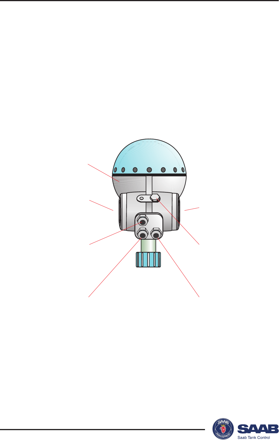
Primary analog output
or
serial communication
(FM: conduit fitting)
Intrinsically safe
analog outputs (or
conduit for non-IS
outputs)
Connection for
Display Panel
CENELEC: EExi
(Optional: EExe)
FM: Intrinsically safe
(Explosion proof)
CENELEC: EExe
FM: Explosion proof
Power supply
(FM: conduit fitting)
Flameproof enclosure
Junction Box
The standard version is equipped with a junction box that con-
sists of a non-intrinsically safe and an intrinsically safe part.
There is also an optional version with two non-intrinsically safe
compartments.
Saab TankRadar® Pro Electrical Installation
3-3
Edition 2. Ref. No: 306010E
54321
X1 >
A
EExe
12345
+tuO
)yramirP(
-tuO
)yramirP(
rewoP
+/1L/L
rewoP
-/2L/N
toN detcennoc
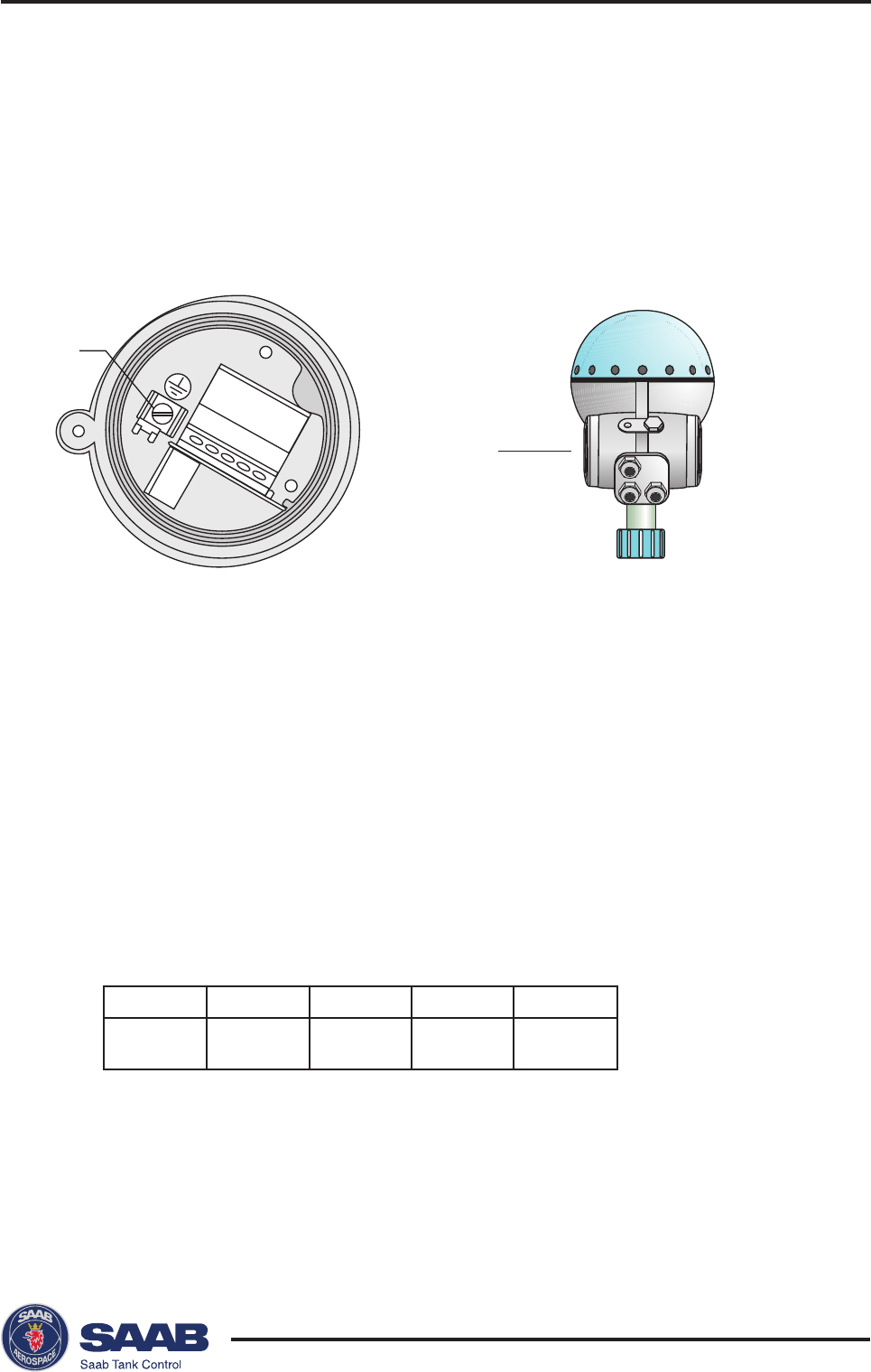
External Connections
Non-Intrinsically SafeJunction Box -EEx e
This Junction Box is for non-intrinsically safe connections and
power supply.
1-2 Non-intrinsically safe HART/4-20 mA primary analog output,
or
TRL/2 Bus
3-4 Power supply input
5Not connected
AElectrical safety ground terminal
Note: redundant when the transmitter is grounded according to
CENELEC.
Cable shield
Connect the shield to the cable glands.
3-4
Edition 2. Ref. No: 306010E
Saab TankRadar® ProElectrical Installation
45
3
2
16
< X2
A
EExi
123456
+tuO
)yramirP(
-tuO
)yramirP(
+tuO
)yradnoceS(
-tuO
)yradnoceS(
+PD SPD
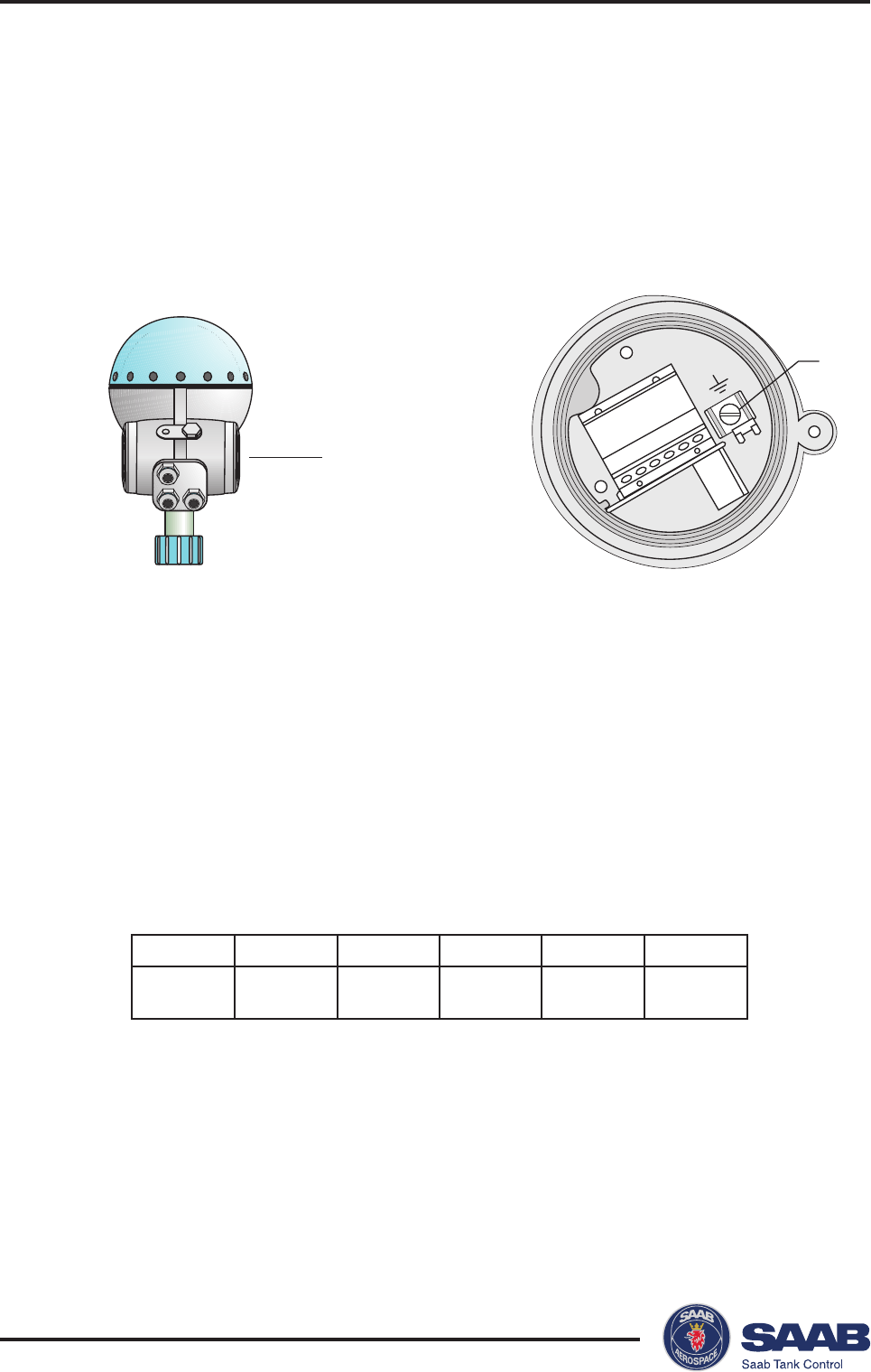
Intrinsically Safe Junction Box - EEx i
This Junction Box is for intrinsically safe connections and for
connection of the Display Panel.
1-2 Intrinsically safe HART/4-20 mA primary analog output.
3-4 Secondary analog output.
5-6 Display panel.
AGround terminal for Display Panel.
Cable shield
Connect the shield to the cable glands.
Saab TankRadar® Pro Electrical Installation
3-5
Edition 2. Ref. No: 306010E
32
4
51
< X2
A
EExi/e
12345
desutoNdesutoN
+tuO
)yradnoceS(
-tuO
)yradnoceS(
toN detcennoc
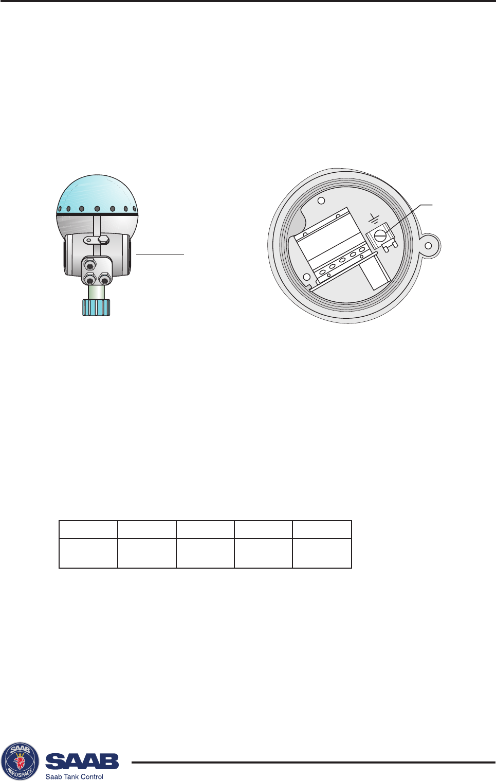
Alternative Non-intrinsically Safe Junction Box
This is the standard intrinsically safe Junction Box (EExi) fitted
with an alternative connector for connection of non-IS output if
required.
1-2 Not used
3-4 Non-intrinsically safe Secondary Analog Output
5Not connected
AGround terminal (not used)
Cable shield
Connect the shield to the cable glands.
3-6
Edition 2. Ref. No: 306010E
Saab TankRadar® ProElectrical Installation
Field Bus Modem
X1
1
2
3
4
5
Junction Box EEx e
100-240 VAC
or
24-48 DC
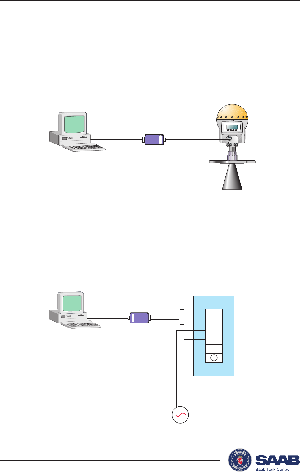
Connecting to a TRL2 Bus Interface
Use a Field Bus Modem (FBM) for a Pro transmitter equipped
with a TRL2 interface.
Connect to the non-intrinsically safe junction box (EEx e).
Saab TankRadar® Pro Electrical Installation
3-7
Edition 2. Ref. No: 306010E
X1
Junction Box
EEx e
1
2
3
4
5
100-240 VAC
or
24-48 VDC
123
456
78
9
250
Ω
V
s
X1
Junction Box
EEx e
1
2
3
4
5
100-240 VAC
or
24-48 VDC
123
456
78
9
Voltage compli-
ance 7-30 V
Input impedance
<300 Ohm
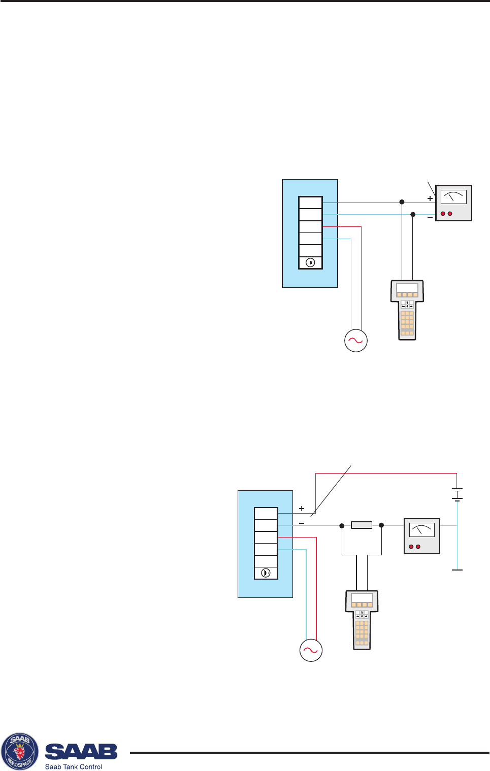
Connecting HART devices
Active output (internal loop supply)
Passive output (external loop supply)
A hand-held terminal or
a HART modem should
not be connected di-
rectly across an external
power supply. Instead,
it should be connected
across a load resistor of
about 250 Ω.
For Pro gauges with active
output a hand-held terminal or
a HART modem can be con-
nected as follows:
3-8
Edition 2. Ref. No: 306010E
Saab TankRadar® ProElectrical Installation
123
456
789
Analog instrument
and/or DCS system
HART
interface
Hand Held HART
Communicator
RTG 40
123
456
789
Hazardous Area Non-Hazardous Area
RTG 40
Zener
barrier
Analog instrument
and/or DCS system
Hand held HART
communicator
HART
interface
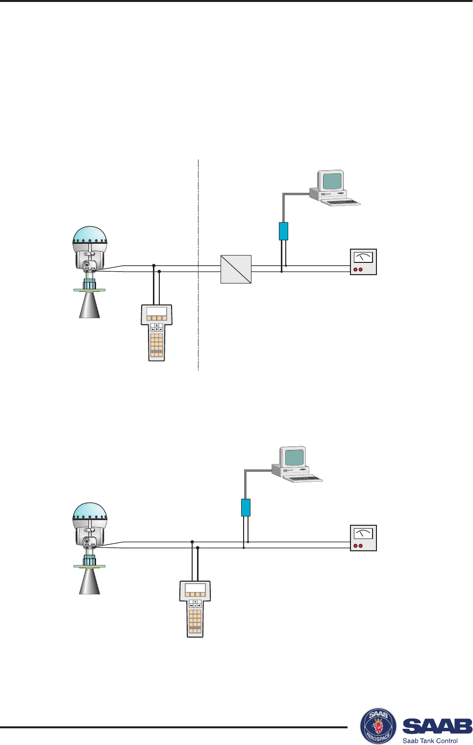
Intrinsically safe conditions
A hand-held HART communicator can be connected in the
hazardous area. The HART interface must be connected via a
zener barrier in the safe area.
Non-Intrinsically safe conditions
Saab TankRadar® Pro Electrical Installation
3-9
Edition 2. Ref. No: 306010E
Gnd
Gnd
D
Vcc
Level
24500
MENU ITEM GRPH
mm
Junction Box
EEx i
6
5
4
3
2
1
X2
IS Ground
DPS
DP +
+
Gnd
Signal
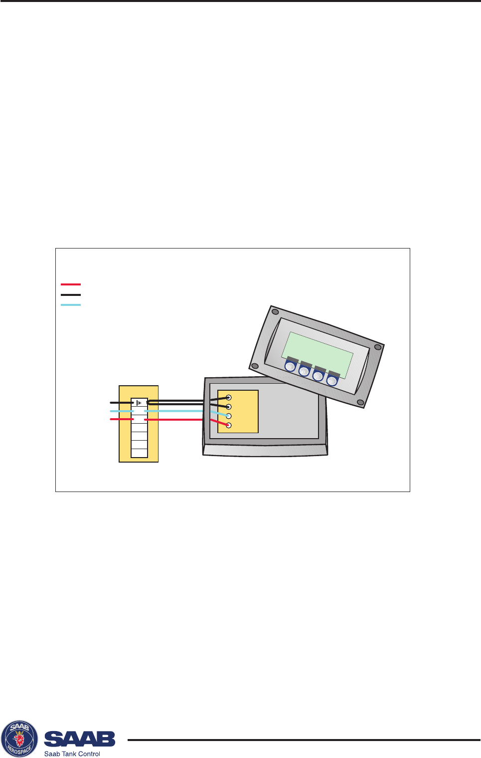
Connecting the Display Panel
The Display Panel is intrinsically safe and may only be used
when permanently mounted directly on the enclosure with two
separate grounding wires.
There are four wires to be connected to the X2 terminal:
• two grounding wires X2 ground terminal
• signal wire terminal 6
• Display Panel supply voltage terminal 5
3-10
Edition 2. Ref. No: 306010E
Saab TankRadar® ProElectrical Installation
NE
P
AS
OU
V
R
IR
S
O
U
S
T
E
N
S
IO
N
.
H
AZ
A
R
D
O
U
S
A
T
M
OS
PH
E
R
E
S
DO
NO
T
O
P
EN
W
H
EN
EN
E
R
G
IZ
E
D.
T
O
P
R
E
V
EN
T
I
GN
I
TI
ON
OF
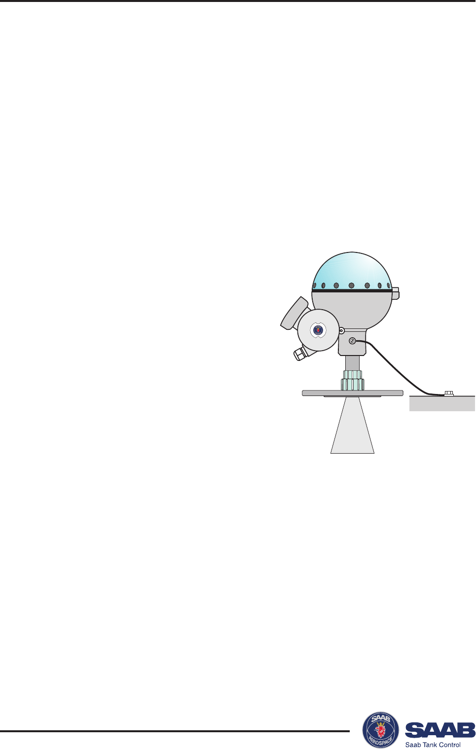
Cables
Depending on local requirements, cable
glands or explosion proof conduits must
be used for connection to the non-
intrinsically safe junction box (EEx e).
For the connection to the instrinsically
safe junction box (EEx i) use cable
glands with integral shield connection
for cable diameter 6-12 mm or conduit.
Use shielded instrument cable 0.5 mm2
(AWG 20) for analog outputs and serical
communication.
Safety
The TankRadar Pro enclosure is flame-
proof and may not be opened while the
transmitter is energized and a flammable
atmosphere is present. Saab Tank Con-
trol will not take any responsibility for
local regulations defining conditions
when flameproof enclosures are allowed
to be opened when energized.
Note! Make sure that you do not mix
up intrinsically safe and non-
intrincisally safe wires.
Power Supply
You can use either DC or AC, depend-
ing on what type power supply unit that
is installed in the transmitter. Nominal
supply voltage is:
• 24-48 VDC,
• 100-240 VAC, 50/60 Hz.
See label on the transmitter housing for
information on which supply voltage to
use.
There is no voltage selector in the
electronics compartment since the
transmitter power supply unit automati-
cally adapts to the available voltage
within specified limits.
Grounding
CENELEC
The flameproof enclosure must be
connected to a potential equalizing
network or the tank shell or according to
national code of practice.
This grounding also serves as electrical
safety ground. Additional connection to
the protective ground terminal of termi-
nal X1 in Junction Box EExe is not
recommended except where required
according to national code of practice. A
ground loop with circulating current
may occur. See also the Special Safety
Instruction.
FM
Grounding is accomplished through the
conduit pipes.
Saab TankRadar® Pro Electrical Installation
3-11
Edition 2. Ref. No: 306010E
System Overview
Display Panel
Connect the intrinsically safe Display
Panel to terminals 5, 6 and ground in
the intrinsically safe (EExi) junction box.
Analog Outputs
There are two analog outputs which can
be of passive or active type (external or
internal loop supply). The primary
output has a HART interface.
Connect the primary analog output to
terminals 1 and 2.
Use the EExe junction box for non-
intrinsically safe applications, and the
EExi junction box for intrinsically safe
applications.
Digital Communication
Saab TankRadar Pro can be equipped
with HART interface or Saab TRL/2
Bus interface.
The Saab TRL/2 Bus may only be
connected to the non-intrinsically safe
(EExe) junction box.
Connect the serial data transmission
cables to terminals 1 and 2.
Power Supply
Saab TankRadar Pro operates on 100-
240 V AC or 24-48 V DC. Check the
label on the transmitter housing that the
correct power supply board is installed.
Connect the power supply to terminals
3 and 4 in the non-intrinsically safe
Junction Box (EEx e).
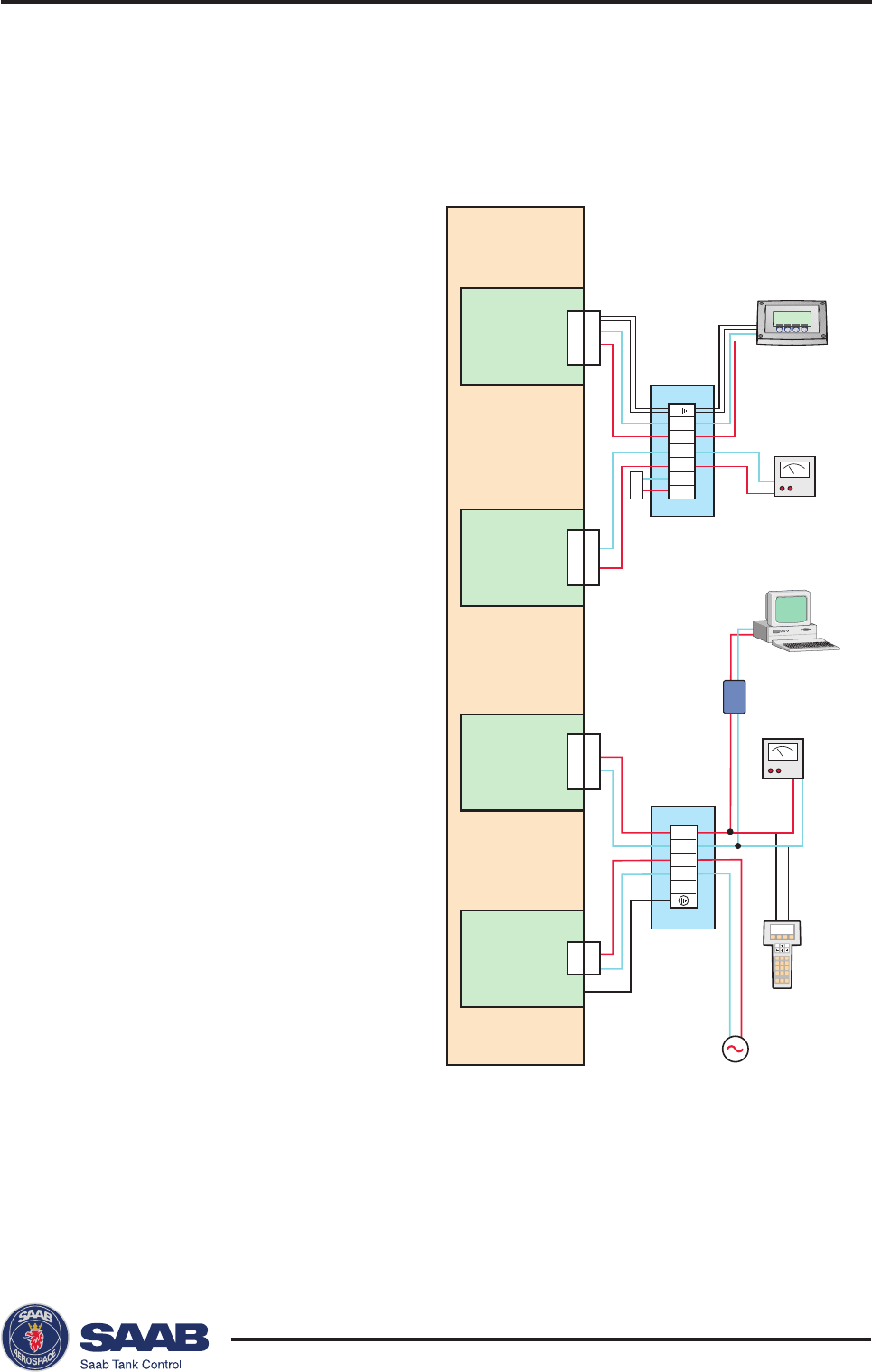
Schematic illustration of Pro trans-
mitter connections
X2
X1
X7
Display Panel
Interface
(DI40)
X7
Level
24500
MENU ITEM GRPH
mm
X3/X5
X3
Junction Box
EEx i
Junction Box
EEx e
HART®
Interface
1
2
3
4
5
6
5
4
3
2
1
HART modem +
Analog Output
(HM40 + IS40)
Main Board
Power Supply
Unit
(AC40 or DC40)
X4
X4
100-240 VAC
or
24-48 VDC
Extra Analog
Output
(XA40 + IS40)
X3/X6
X6
123
456
789
X5
3-12
Edition 2. Ref. No: 306010E
Saab TankRadar® ProElectrical Installation
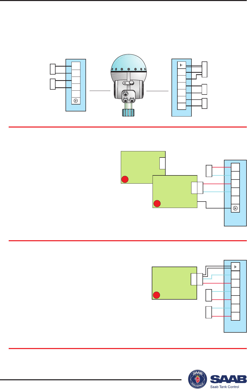
X2
5
4
3
1
2
6
X5 X6
DPS
DP+
SO-
SO+
PO+
PO-
IS Gnd
X7
DI40
X7
P
5
4
3
1
2
X1
L+
L-
PO+
PO-
X3
X4
X4
D
DC40
X4
A
AC40
X2
6
5
4
3
2
1
X5 X6 X7
X1
1
2
3
4
5
X3X4
Non-Intrinsically Safe (EEx e) Intrinsically Safe (EEx i)
Internal Connections
Option Description Board
0 No Display Panel NA
P Display Panel DI40
Option Description Board
A 100 - 240 VAC AC40
D 24 - 48 VDC DC40
Power Supply
Display Panel
Saab TankRadar® Pro Electrical Installation
3-13
Edition 2. Ref. No: 306010E
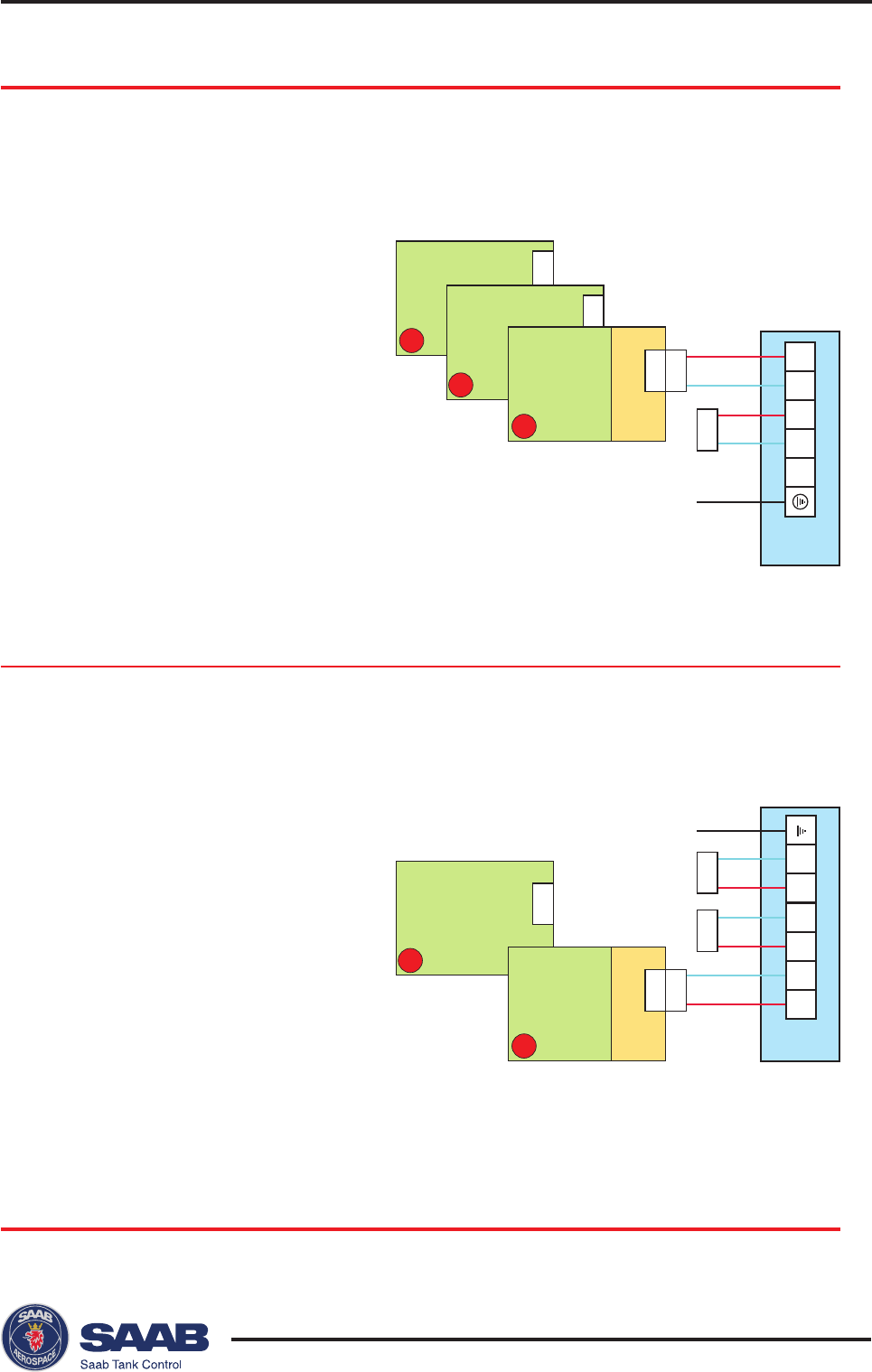
X2
5
4
3
1
2
6
HM40
X5
X5
1D
X6 X7
IS Gnd
IS40
HM40
X5
1B
DPS
DP+
SO-
SO+
PO+
PO-
X3
2A
TM40
1C
HM40
X3
5
4
3
1
2
X1
L+
L-
PO+
PO-
X3
X4
IS40
X3
1A
HM40
Primary Output
Non-Intrinsic Safety (EEx e)
Intrinsic Safety (EEx i)
Option Description Board
1A Non-intrinsically safe HM40+IS40
HART/4-20 mA,
active.
1C Non-intrinsically safe HM40
HART/4-20 mA,
passive
2A TRL2 Bus TM40
Option Description Board
1B Intrinsically safe HM40+IS40
HART/4-20 mA,
active
1D Intrinsically safe HM40
HART/4-20 mA,
passive
3-14
Edition 2. Ref. No: 306010E
Saab TankRadar® ProElectrical Installation
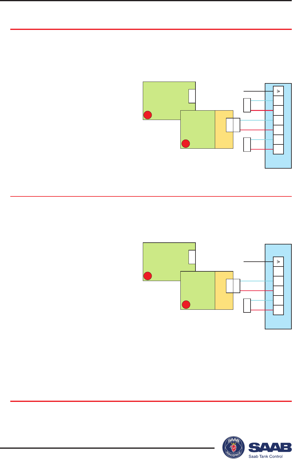
X2
5
4
3
1
2
6
XA40
X6
X5
D
X7
IS Gnd
IS40
XA40
X6
B
DPS
DP+
SO-
SO+
PO+
PO-
X6
X2
5
4
3
1
2
XA40
X6
X5
C
IS40
XA40
X6
SO-
SO+
PO+
PO-
X6
A
Secondary Output
Intrinsic Safety (EEx i)
Option Description Board
A Non-intrinsically safe XA40+IS40
4-20mA active
C Non-intrinsically safe XA40
4-20mA passive
Note! This junction box is normally used for intrinsically safe connections. This
version is a non-intrinsically safe option equipped with an alternative
connector for non-intrinsically safe output.
Option Description Board
B Intrinsically Safe XA40+IS40
4-20mA active
D Intrinsically Safe XA40
4-20mA passive
Non-Intrinsic Safety (EEx e)
Saab TankRadar® Pro Pro Setup
4-1
Edition 2. Ref. No: 306010E
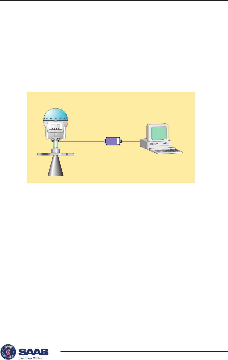
4 Pro Setup Software
The Pro Setup software is an easy to use PC program for con-
figuration of the Saab TankRadar Pro transmitter. It is designed
to run under Windows95/NT4.0. It also includes options for
viewing tank data as well as options for advanced service.
It is a simple task to start and configure the TankRadar Pro trans-
mitter. When the gauge is mounted on the tank flange, and the
cables are properly connected you only need to run through a
straightforward configuration procedure to start the transmitter.
In this procedure you will set a few parameters to optimize the
performance of the gauge for your particular application:
Tank dimensions
Type of application.
Analog out: source, range and alarm mode.
Volume calculations (optional).
Tank environment (for the disturbance echo handling).
PC
Modem
RTG 40
Saab TankRadar® ProPro Setup
4-2
Edition 2. Ref. No: 306010E
System Requirements
Processor: Pentium
Operating system: Windows95/NT 4.0
Memory: 16 MB
Hard disk space: 5 MB
Installing the Pro setup software
To install TankRadar Pro configuration software on your compu-
ter do the following:
1 Start Windows and make sure that no applications are running.
If you run Pro Setup under Windows 95, upgrade Windows 95 by
running the Dcom95.exe upgrade kit.
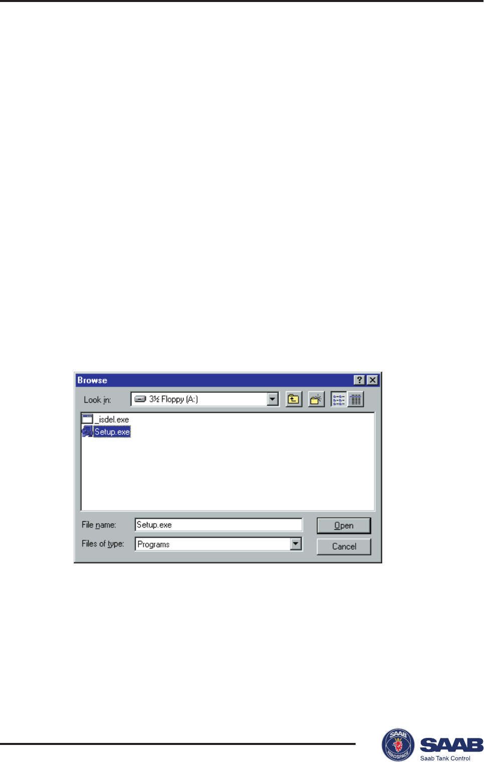
2 Insert the TankRadar Pro setup disk.
3 Select the Run command on the Start menu.
Browse to the diskett drive and select the setup file. Follow the
instructions.
Saab TankRadar® Pro Pro Setup
4-3
Edition 2. Ref. No: 306010E
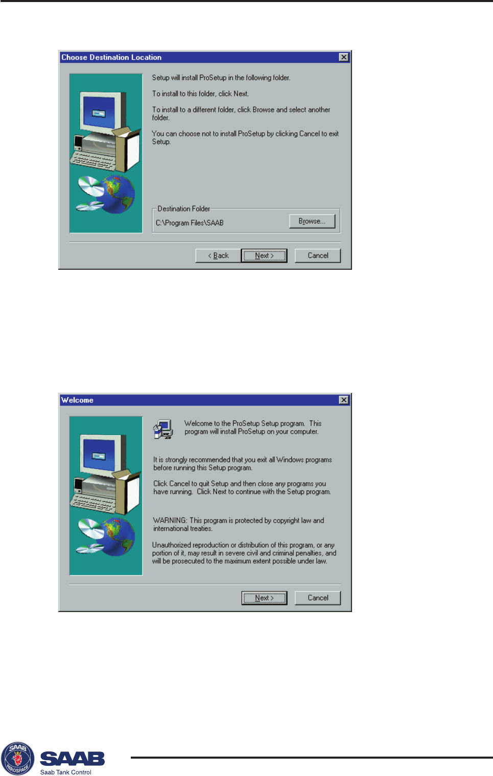
4 Choose installation directory.
Program Files\Saab
is the default directory. Click the Browse button if
you want to specify another installation directory.
Click the Next button.
5. Follow the instructions in the installation wizard.
Click the Next button.
Saab TankRadar® ProPro Setup
4-4
Edition 2. Ref. No: 306010E
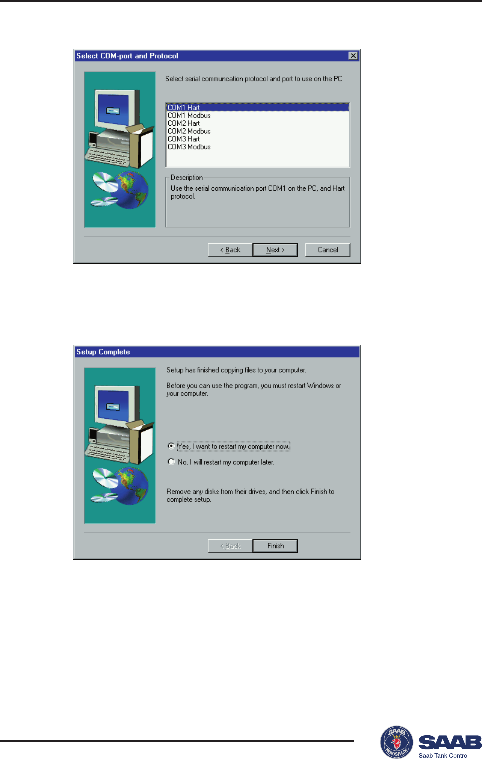
6 Specify the Com port and communication protocol you will use to
connect the gauge. Com port and protocol can be changed later.
7 Finish the installation.
Saab TankRadar® Pro Pro Setup
4-5
Edition 2. Ref. No: 306010E
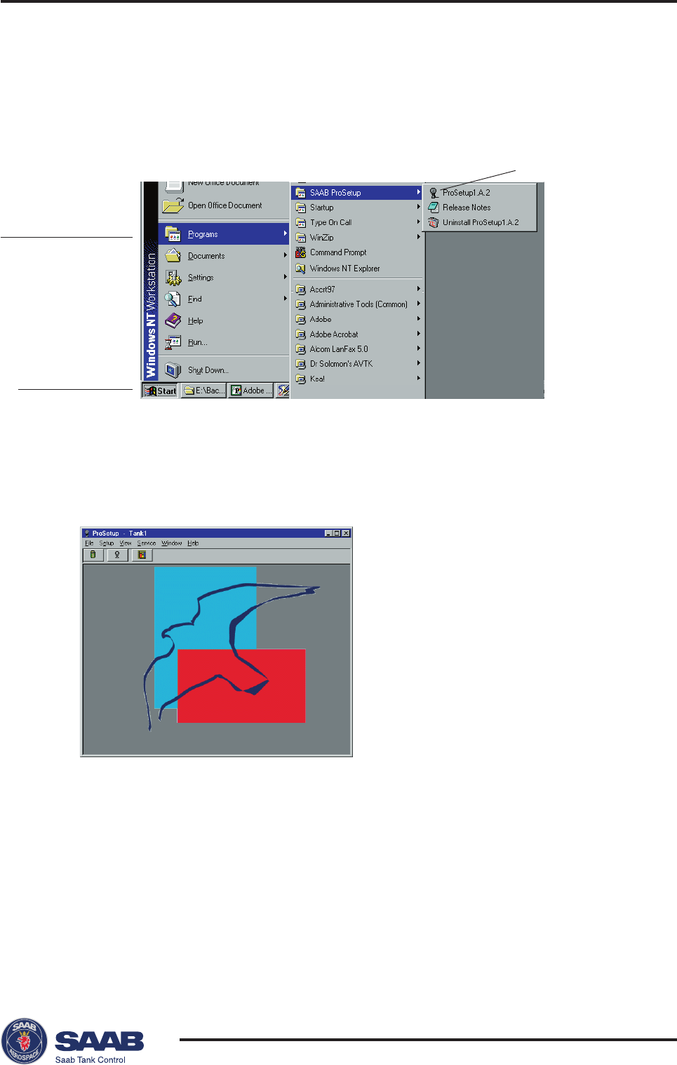
Starting the Pro Setup Program
Do the following to start Pro Setup:
1 Click the Start button in the Windows95 Task bar.
Note! While Pro Setup is running, the Win95 Task Bar contains two
buttons named “Pro Setup” and “Saab TankRadar IO Master
Server” .The last button refers to a communication program support-
ing Pro Setup. Normally, you do not need to open this window unless
you need to change communication parameters. It can also be used to
view communication on screen.
2 Open the Programs menu.
3 Open the Saab ProSetup folder.
4 Click the Pro Setup icon.
Pro Setup icon
Start button
Programs menu
Saab TankRadar® ProPro Setup
4-6
Edition 2. Ref. No: 306010E
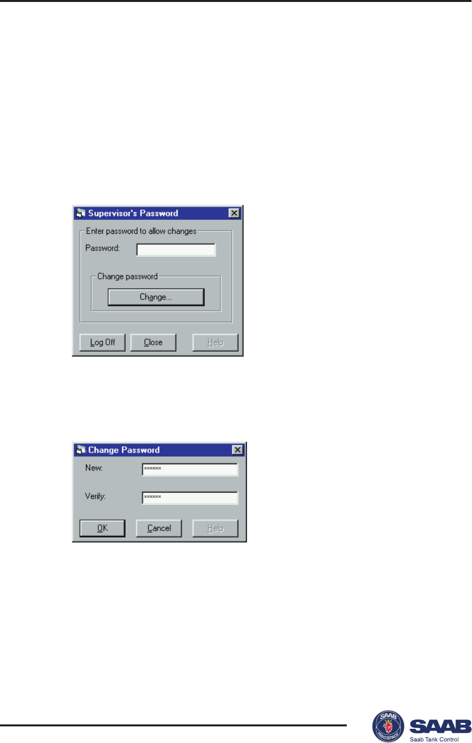
Setting a Password
You can set a password to prevent unauthorized changes of the
transmitter configuration. Then you will have to enter the pass-
word in order to obtain access to configuration and service op-
tions. You do not need to enter a password for viewing tank data.
To set a password do the following:
1 Select Password from the Setup menu.
2 Leave the Password input field blank if no password has been
set.
3 Click the Change button.
4 Enter a new password in the New input field.
5 Verify the new password and click the OK button.
Response: the Change Password window is closed.
6 Click the Close button in the
Supervisor´s Password
window.
Saab TankRadar® Pro Pro Setup
4-7
Edition 2. Ref. No: 306010E
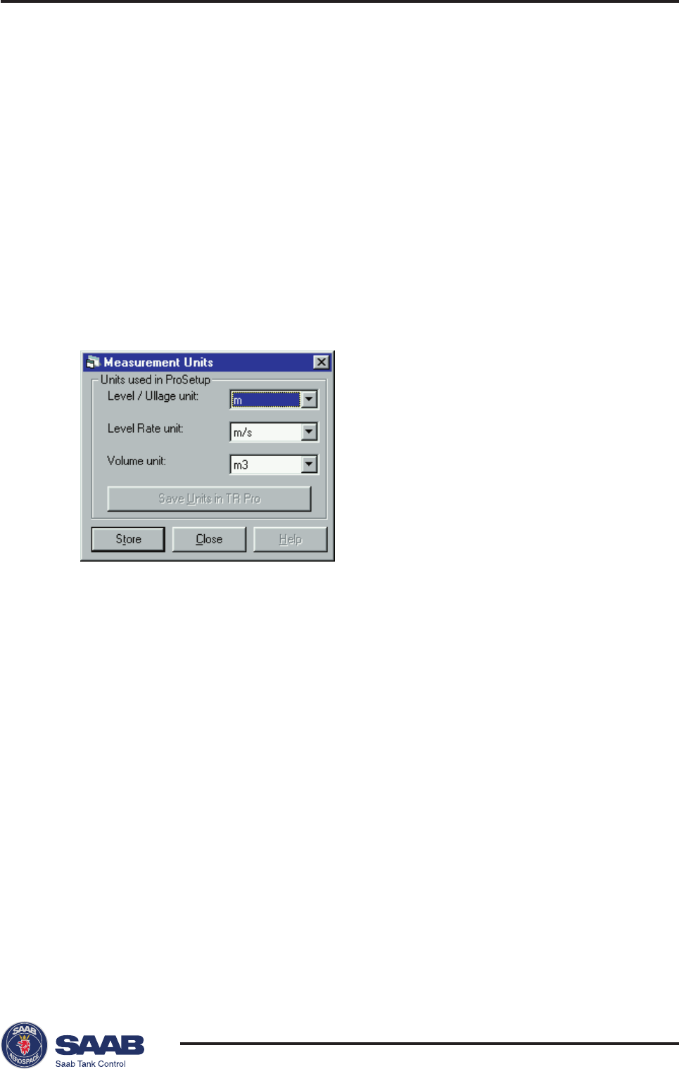
2 Select the desired units for Level/Ullage, Level Rate and volume.
3 Click the Store button.
Logging on to a password protected system.
To log on to a password protected system do the following:
1 Select Password from the Setup menu.
2 Enter your password in the Password input field.
3 Click the Log On button.
4 When your password is accepted click the Close button.
Setting measurement units
1 Select Measurement Units from the Setup menu.
Saab TankRadar® ProPro Setup
4-8
Edition 2. Ref. No: 306010E
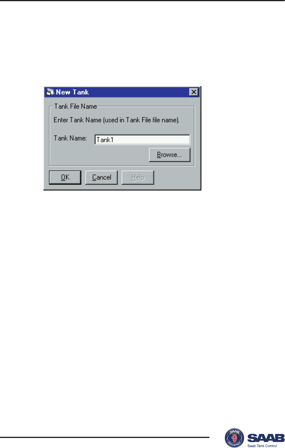
Installing a Pro Transmitter
Do the following to install and configure a Pro transmitter:
1Connect to a TankRadar PRO transmitter.
1 Select New Tank from the File menu in the
Main
window.
2 Enter a tank name to associate with the tank and click the OK
button.
Response: the Tank Radar PRO Setup window is opened with the
address tab active.
Saab TankRadar® Pro Pro Setup
4-9
Edition 2. Ref. No: 306010E
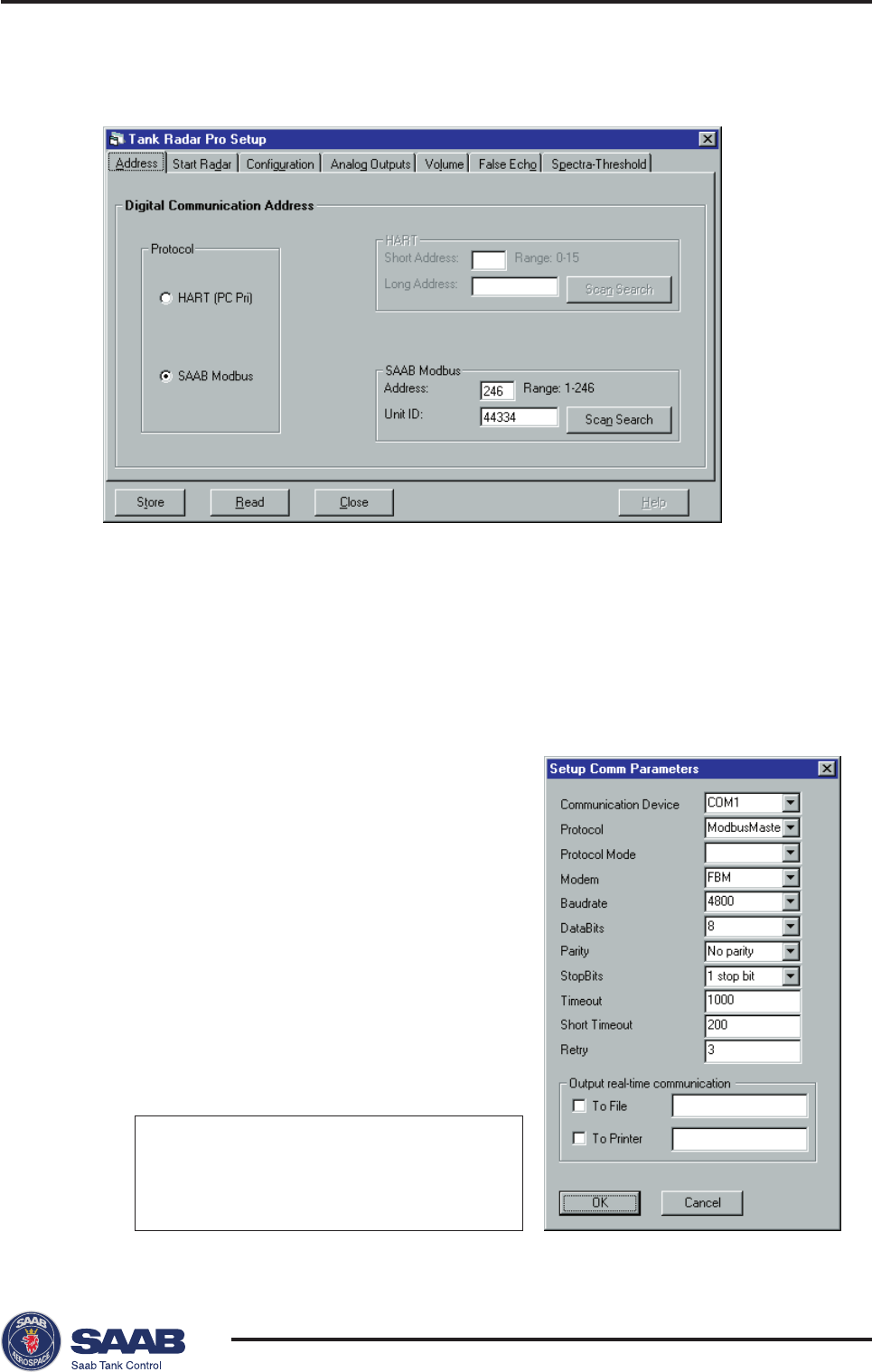
2Enter protocol and address data.
1 In the Protocol box specify the protocol that you will use for the
serial communication.
• Choose HART if your gauge is equipped with an analog output
and a HART interface (make sure that the HART interface is
correctly installed according to the recommendations for active
and passive analog outputs, see
Electrical Installation
).
- or -
• Choose Saab Modbus if your gauge is
equipped with a TRL/2 Bus interface.
Make sure that you select the same
protocol that was specified during the Pro
Setup installation. If you need to change
the current communication settings (if you
for example have changed modem), open
the IO Master Server program from the
Windows95 task bar. Choose Parameters
from the Format menu to view the com-
munication parameters. The following
settings are used for TRL2 Bus and HART
interface:
HART TRL2 Bus
Protocol HartMaster ModbusMaster
Baudrate 1200 4800
Parity Odd No parity

Saab TankRadar® ProPro Setup
4-10
Edition 2. Ref. No: 306010E
2 Set the communication address. To set a new address you have to
know the current address or the Unit ID/Long Address (HART) to
establish communication with the gauge. The default address is 0
for HART and 246 for Modbus.
To change the address, do the following:
1 Enter the address that is currently stored in the gauge (the default
address for a new gauge) into the address field.
2 Click the Read button.
Response: the Unit ID/Long Address is displayed.
3 Set the address of your own choice.
4 Click the Store button.
If the transmitter did not respond to the old address do the
following:
1 Enter the Unit ID (Saab Modbus)/Long address (HART) in the
corresponding field. The Unit ID can be found on the label, see
Chapter 3.
2 Enter the desired address in the Address field
3 Click the Store button.
If the transmitter did not respond to the old address, and you
can not find the Unit ID, (for example if the transmitter is lo-
cated far from the configuration PC), do the following:
1 Click the Scan Search button. Pro Setup automatically scans
through a range of possible addresses in order to find connected
devices.
Note! For Modbus devices the scan may be very time consuming if
the default address is still valid. Normally the scan starts at address
0 for HART buses and address 1 for Saab Modbus. You can enter
other start addresses in the Address field in order to reduce the
scanning time.
This function may be useful if you want to find out which addresses
that are currently used by connected devices.
2
Stop the scanning when the correct device is found.
The scan continues until a device is found, or until the search is
stopped by the operator.
3
Enter the address that you want to use for the particular device.
4
Click the Store button.
Now the address is stored in the gauge and will be used for the
communication between the PC and the transmitter.
Saab TankRadar® Pro Pro Setup
4-11
Edition 2. Ref. No: 306010E
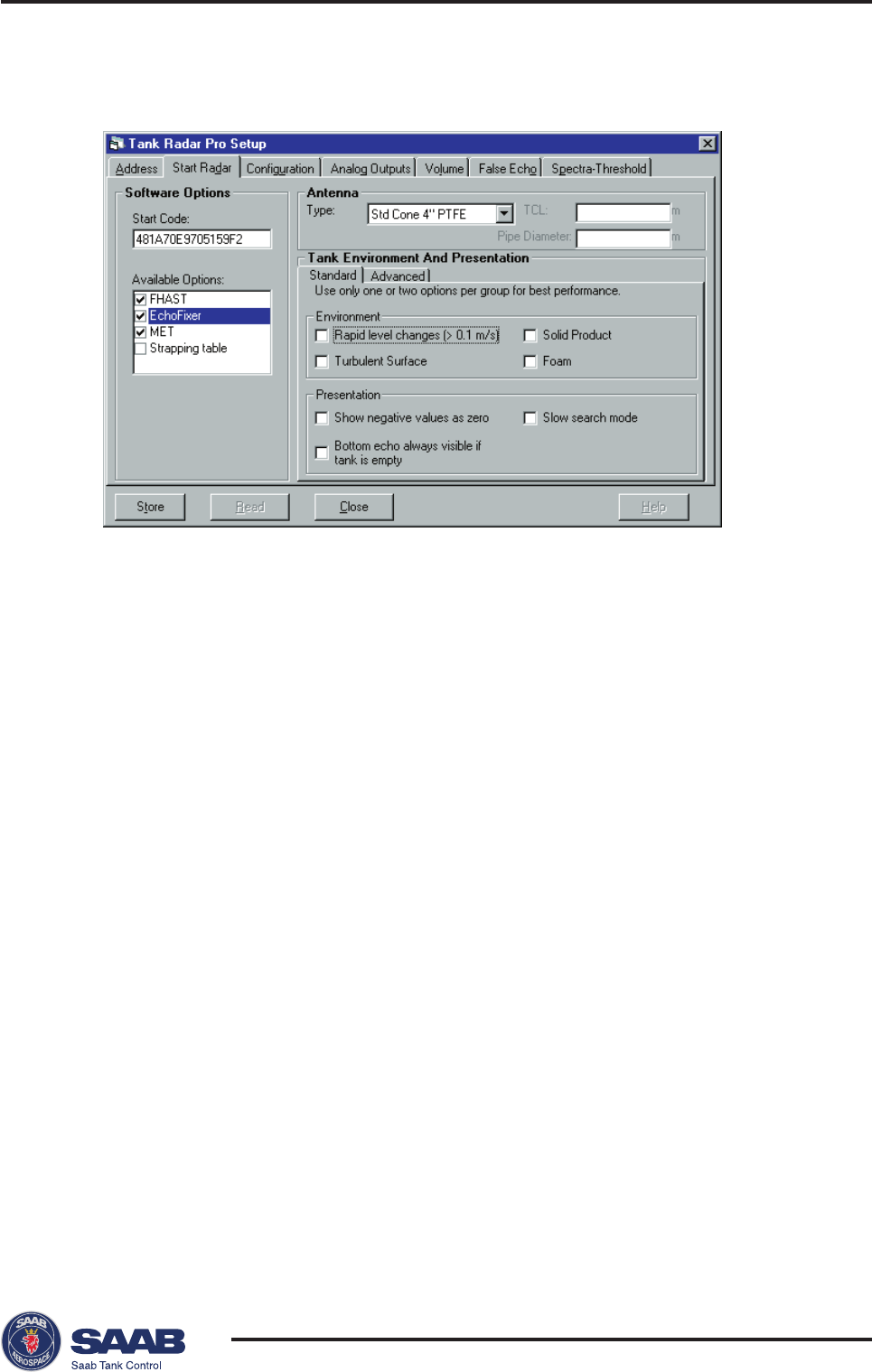
3Select the Start Radar tab
1 Click the Read button.
Response: the current settings and the Start Code are displayed.
2 Check that the correct set of available options is displayed. Contact
your local representative if you like to add one or more of the follow-
ing software options: EchoFixer, MET, FHAST filtering or strap table
volume calculations.
3 Mark the check boxes that corresponds to available software op-
tions that you want to enable.
Note! The strapping table option can only be enabled by selecting the
Strapping Table option in the Volume tab.
4 Select the type of antenna to be used.
HP=high performance (Hastelloy, Tantalum, Titanium, Monel).
Std=standard.
P=PTFE tank sealing.
Q=Quartz tank sealing.
C=Ceramic.
Enter the pipe inner diameter if the antenna is mounted in a still
pipe.
The TCL parameter is entered for non-standard antennas only.

Saab TankRadar® ProPro Setup
4-12
Edition 2. Ref. No: 306010E
5 In the Tank Environment and Presentation Standard tab there are
two groups of parameters. In the Environment box mark the check
boxes that correspond to the conditions in your tank:
Rapid level changes
optimizes the transmitter for measurement
conditions where the level changes quickly
due to filling and emptying of the tank.
Turbulent Surface
This parameter may be used if the tank
e.g. contains boiling products causing a
turbulent surface. By setting this param-
eter the performance of the transmitter will
be improved when there are small and
quickly changing amplitudes and levels.
Foam
Setting this parameter optimizes the trans-
mitter for conditions with weak and varying
surface echo amplitudes.
Solid Products
Setting this parameter optimizes the trans-
mitter for products which are not transpar-
ent for radar signals. The effect will be
more reliable handling of false echoes
from beams.
You should not choose more than two options for best performance.
In the Presentation box the following options are available:
Negative values
Set this parameter if you want levels below
as Zero
the reference point at the bottom of the
tank to be displayed as zero. This param-
eter can be used if you have set a C
distance in the tank geometry configura-
tion (see the
Configuration
tab and chapter
Tank Distances
).
Bottom Echo always
Mark this check box if the tank shape
visible if empty tank
allows bottom echoes to be detected. By
setting this parameter the bottom echo will
be treated as a disturbance echo to facili-
tate tracking of weak surface echoes close
to the tank bottom. If this parameter is not
set, searching for a lost surface echo is
Saab TankRadar® Pro Pro Setup
4-13
Edition 2. Ref. No: 306010E
restricted to a region close to the tank
bottom (Related database register:
Full
tank detection area, 1516
).
Do not set this parameter if the bottom
echo is not visible.
Slow Search
This variable controls how to search for
the surface if a surface echo is lost. With
this parameter set the transmitter starts
searching for the surface at the last known
position, and gradually increases the width
of the search region until the surface is
found. If this varaible is not set the trans-
mitter searches through the whole tank.
This parameter may typically be used for
tanks with turbulent conditions.
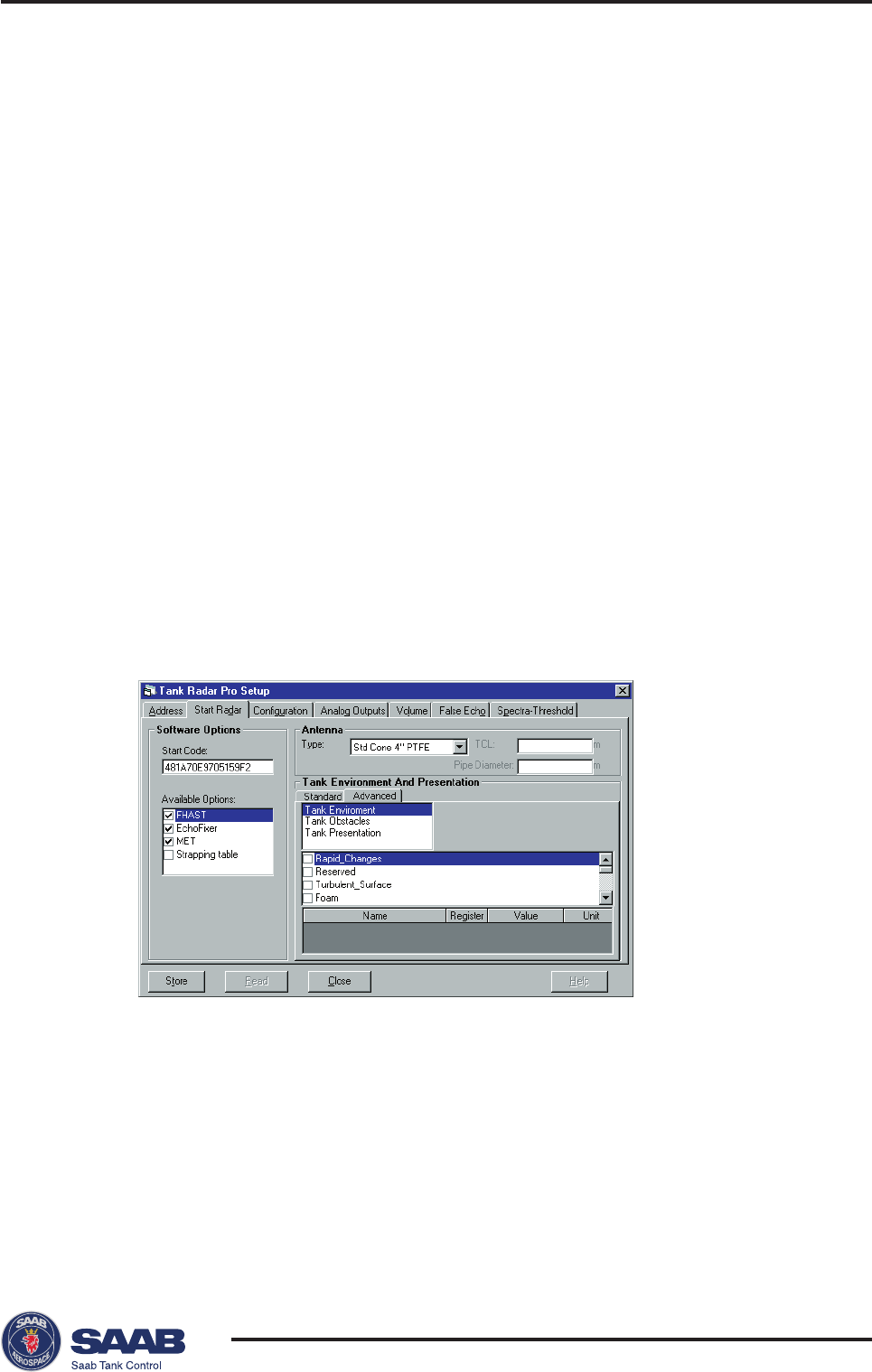
6 Click the Store button if no further settings are required,
- or -
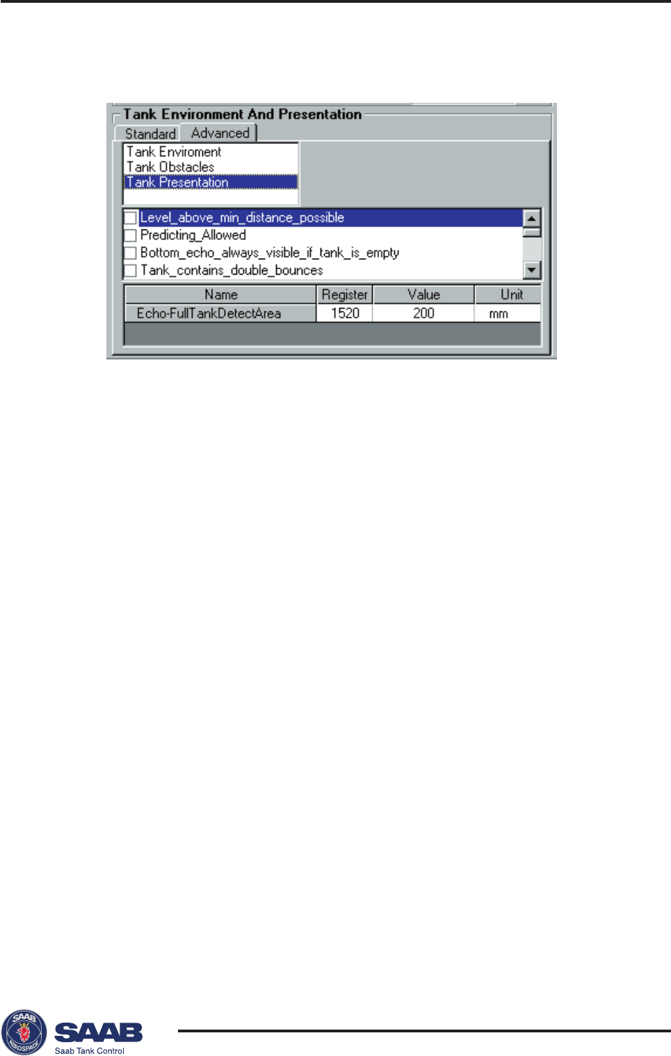
open the Tank Environment and Presentation Advanced tab to
make further settings:
For some parameters , e.g. Slow Search in the Tank Presentation
group, there is a related holding register which may need to be
changed in order to achieve the best measurement result. For these
parameters the related database registers appear in the bottom
pane of the Advanced tab.
You can edit the register value by simply putting the cursor in the
corresponding input field and enter the desired value.
Saab TankRadar® ProPro Setup
4-14
Edition 2. Ref. No: 306010E
See description of the Tank Environment parameters in the
Standard tab.
Note! The Tank Environment parameter settings overrides some of the
Holding register settings.
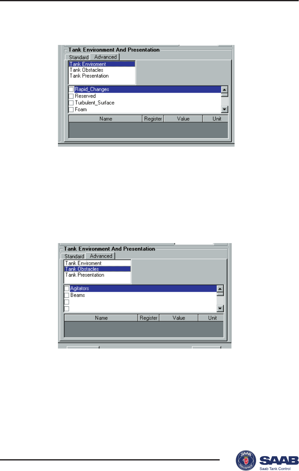
Tank Obstacles
Tank Environment
This option is not used in the current version of the Pro application
software.
Saab TankRadar® Pro Pro Setup
4-15
Edition 2. Ref. No: 306010E
Tank Presentation
Level above min
If the surface echo is lost in the vicinity of
distance possible
the antenna, full tank is indicated and
searching for the surface echo is limited to
a region close to the antenna.
Predicting allowed
Improves the performance when filling or
emptying a tank. Setting this parameter
may reduce the time to detect a lost
surface echo resulting in better tracking of
a moving surface.
Bottom echo always
See description of the Standard tab
visible if tank empty
parameters.
Double bounce
Some radar waves are reflected against
possible
the tank roof and back to the surface
before they are detected by the transmit-
ter. Normally, these signals have a low
amplitude and are therefore neglected by
the transmitter. In some rare cases the
amplitude may be strong enough to lead
the transmitter to interpret the double
bounce as the surface echo. By setting the
Double bounce parameter this type of
measurement situation may be improved.
This function should only be used if the
problem of double bounces can not be

Saab TankRadar® ProPro Setup
4-16
Edition 2. Ref. No: 306010E
solved by changing the mechanical instal-
lation. Related database register:
DoubleBounceOffset
(1522).
Slow search
See description of the Standard tab pa-
rameters. Related database register:
SearchSpeed
(1524).
Double surface
Indicates that there are two liquids in the
tank resulting in two reflecting surfaces.
The upper liquid is must to be partly trans-
parent to the radar signal. If this function is
activated, you can specify which surface to
ignore by setting the
Ignore top surface
parameter.
Ignore top surface
This function should only be used if
DoubleSurface
is set. See description of
Double surface
. If
IgnoreTopSurface
is set
the lower surface will be presented as the
product surface.
Show negative values
See description of the Standard tab
as zero
parameters.
Monotone ullage/level
When a tank is filled the level value may
presentation
fluctuate up and down due to a turbulent
surface. By setting this parameter the
transmitter will not present decreasing
level values for a tank that is being filled
unless the level decreases more than an
amount given by the
MonFilt Hysteresis
parameter (holding register 1058).
For a tank that is being emptied only
decreasing values are presented, unless
the level rises more than an amount given
by the
MonFilt Hysteresis
parameter.

Saab TankRadar® Pro Pro Setup
4-17
Edition 2. Ref. No: 306010E
Invalid level is not set
If the surface echo is lost close to the top
if tank is full or empty
or
close to the bottom of the tank, the level
value full/empty will normally be displayed
as “invalid”. Set this parameter to suppress
the “invalid“ display.
Note! By setting this parameter the analog
output will not enter alarm mode for invalid
levels close to the tank bottom or close to
the antenna.
Click the Store button when all settings are finished.
Saab TankRadar® ProPro Setup
4-18
Edition 2. Ref. No: 306010E
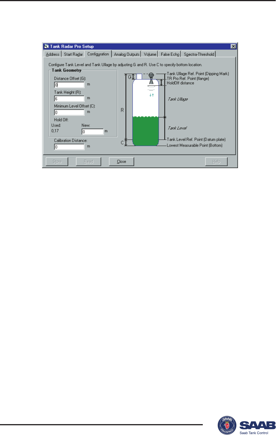
4Select the Configuration tab
1 Click the Read button.
Response: the current settings are displayed.
2 In the Tank Geometry box, enter values for Distance Offset (G),
Tank Height (R) and Minimum Level Offset (C).
The Distance Offset (G) is defined as the distance between the
upper reference point and the flange
(
the flange is referred to as the
Tank Radar Pro Reference Point)
. You can use G to specify your
own reference point at the top of the tank. Set G=0 if you want the
flange as upper reference point. G is defined as positive if you use
an upper reference point above the
TR Pro Reference Point.
For
tanks with an ullage plug for hand dipping the
Tank Ullage Refer-
ence Point (dipping mark)
can be used as upper reference point,
but you can use other reference points as well.
The Tank Height (R) is defined as the distance between the upper
reference point (specified by the Distance Offset G) and the lower
reference point (zero level).
The Minimum Level Offset (C) is used to extend the measurement
range down to the tank bottom. C can not be a negative value. C is
defined as the distance between the zero level (
Tank Level Refer-
ence Point
) and the minimum accepted level. If your zero level is
located above the bottom of the tank, set the C distance equal to

Saab TankRadar® Pro Pro Setup
4-19
Edition 2. Ref. No: 306010E
the distance between the zero level and the tank bottom. Set C=0 if
you use the tank bottom as zero reference point.
The Hold Off (H) distance defines how close to the TR Pro refer-
ence point a level value is accepted. Normally the Hold Off dis-
tance does not need to be changed. However, if there are disturbing
echoes in the upper part of the tank, for example from the tank
nozzle, you can increase the Hold Off distance in order to avoid
measurements in the region close to the antenna.
The Calibration Distance is by default set to zero. It can be used to
compensate for systematic errors due to e.g. disturbances from the
tank nozzle which may be case if the gauge is not mounted properly
according to the free space requirements.
See chapter
6: Tank Distances
for further information on how to set
the tank geometry parameters.
3 Click the Store button.
Saab TankRadar® ProPro Setup
4-20
Edition 2. Ref. No: 306010E
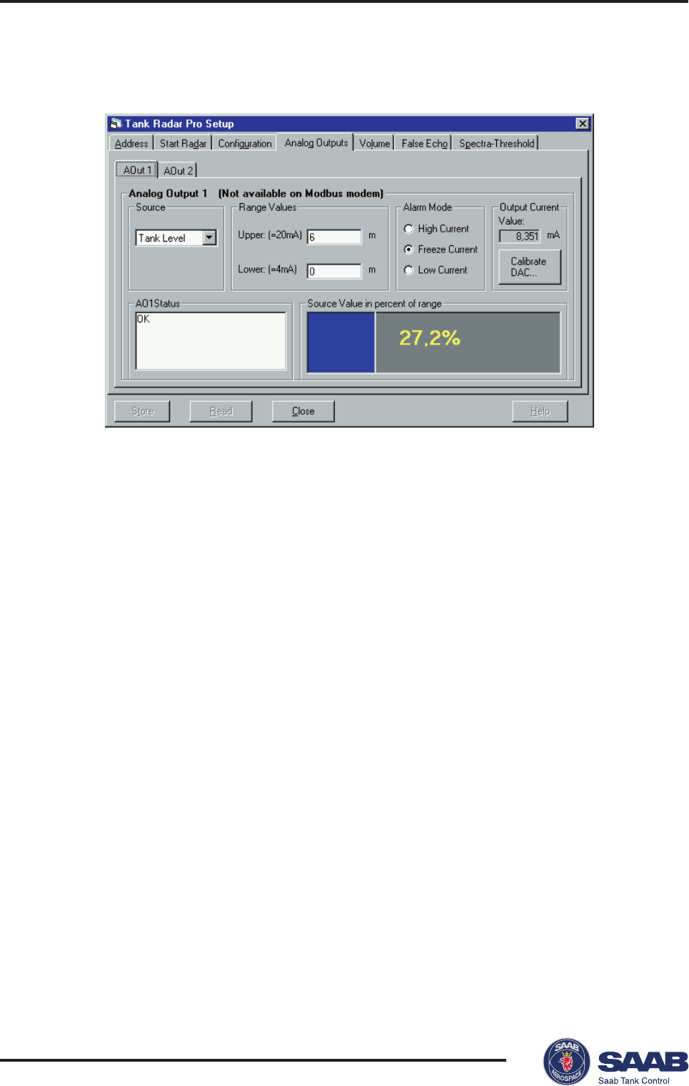
5Select the Analog Outputs tab
1 Click the Read button.
Response: the current settings are displayed.
2 If your transmitter is equipped with a HART® modem select the
Analog Out1 tab. (Analog 1 is note available when using TRL2 Bus
communication).
3 Select the source to control the analog output.
4 Enter the range values that correspond to the analog output values
4 and 20 mA.
5 Enter the alarm mode, i.e the analog out state on measurement
error.
• High: the output current is set to 22 mA.
• Low: the output current is set to 3.8 mA.
• Hold Last Value: the output current is set to the present mea-
surement value at the time when the error occurred.
6 The analog output is calibrated at factory and does normally not
need to be recalibrated. However, if you still need to calibrate the
analog output current, click the Calibrate DAC button and follow
the instructions on the next page.
7 If your transmitter is equipped with an optional analog output select
the Analog Out2 tab and configure as described in steps 2 to 6.
8 Click the Store button to save the current settings.
Saab TankRadar® Pro Pro Setup
4-21
Edition 2. Ref. No: 306010E
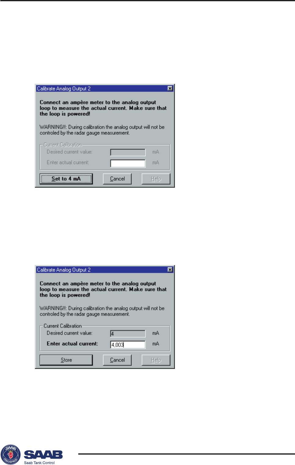
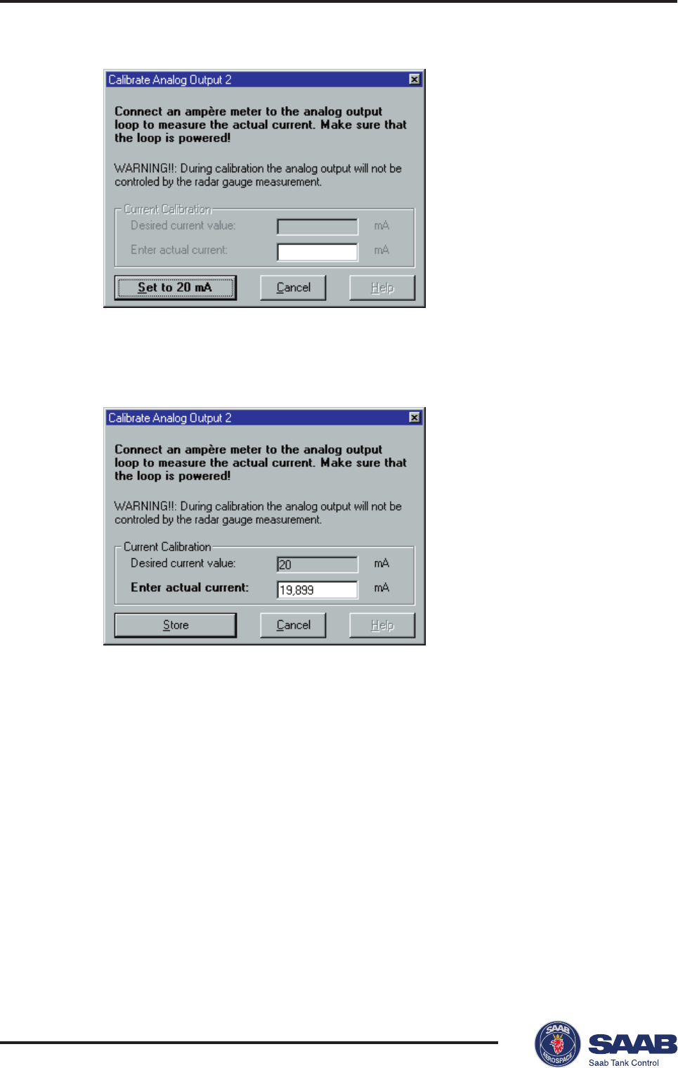
Calibrating the Digital to Analog Converter (DAC)
The Digital to Analog Converter (DAC) is factory calibrated. How-
ever, if you want to check the calibration by measuring the output
current, do the following:
1 Click the Calibrate DAC... button.
2 Read the instruction and the warning.
Note! The analog output will be set to fixed current mode.
Make sure that control systems connected to the output are not
harmed.
3 Click the Set to 4 mA button.
4 Enter the measured output current and click the Store button.
Saab TankRadar® ProPro Setup
4-22
Edition 2. Ref. No: 306010E
5 Click the Set to 20 mA button.
6 Enter the measured output current and click the Store button.
7 Click the Cancel button to close the window and finish the calibra-
tion.
Saab TankRadar® Pro Pro Setup
4-23
Edition 2. Ref. No: 306010E
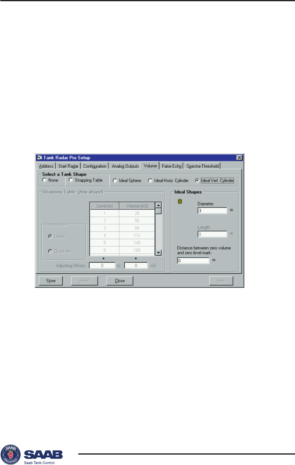
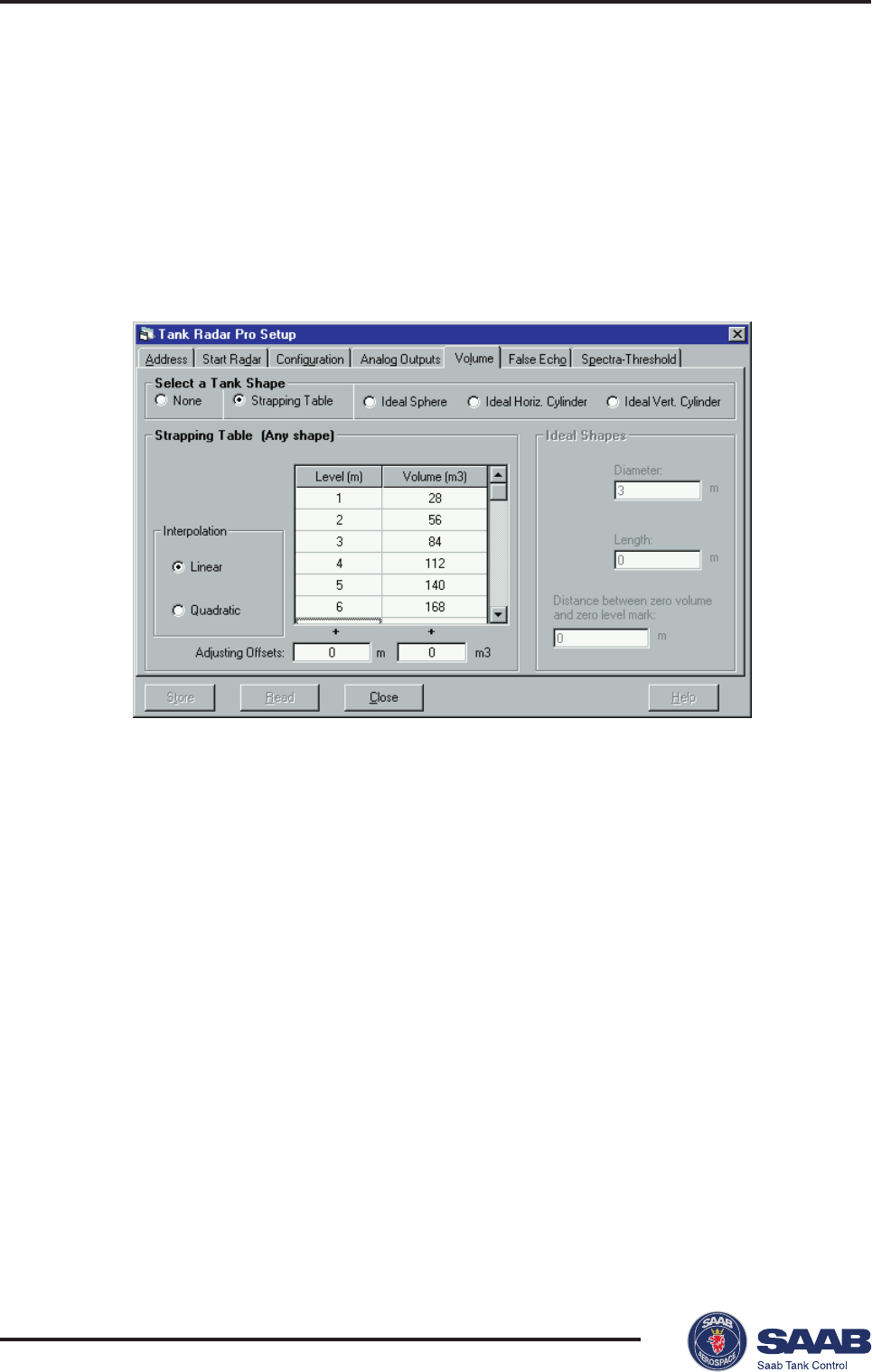
2 Select a tank shape.
Select one of the tank shape options. Choose None if you don´t
want to use volume calculations. Use one of the ideal tank shape
options if approximation of your tank with an ideal tank shape
provides sufficient accuracy. The strapping table can be used for an
arbitrary tank shape. You can enter levels and corresponding vol-
umes to obtain a close match between the actual and the calculated
volume. This option should be used in cases where the tank shape
deviates significantly from an ideal sphere or cylinder, or when you
require high accuracy.
Note! The Strapping Table option can be used only if it is in the list of
available software options in the Start Radar tab.
6Volume Calculations
Pro Setup performs Volume Calculations by using one of two
methods: predefined tank shape or strapping table. The strap-
ping table is an optional function. If it is not available a new
Start Code can be ordered from Saab Tank Control.
To enable Strapping Table select the corresponding option in the
Pro Setup/Volume window.
To configure the TR Pro Transmitter for volume calculations do
the following:
1 Select the Volume tab
Saab TankRadar® ProPro Setup
4-24
Edition 2. Ref. No: 306010E
Ideal tank
Use this option if approximation of your tank with an ideal tank
shape provides sufficient accuracy. Enter the follwoing parameters:
• Tank diameter (or the length if it is a horizontal tank).
• “Distance between zero volume and zero level mark”: set this
parameter if you do not want zero volume and zero level to match
(for example if you want to include volume below the zero level).
Strapping table
• Enter level and corresponding volume values. These figures can
typically be obtained from tank drawings or from certificate from the
tank manufacturer. If the level/volume table is based on a reference
point that is different from your reference point, you can adjust by
adding corresponding offset values in the Adjusting Offsets fields.
The Adjusting Offset is added to every value in the corresponding
column.
• Select which interpolation method to use for calculating vol-
umes between the strapping points. Normally, linear interpolation is
the preferred method. For spherical tanks, quadratic interpolation
may result in a smaller error. However, it may be necessary to try
both methods in order to evaluate which one is best in your particu-
lar case. By using linear interpolation and a sufficient number of
values in the strapping table, the interpolation error can normally be
reduced to a minimum.
3 Click the Store button.
Saab TankRadar® Pro Pro Setup
4-25
Edition 2. Ref. No: 306010E
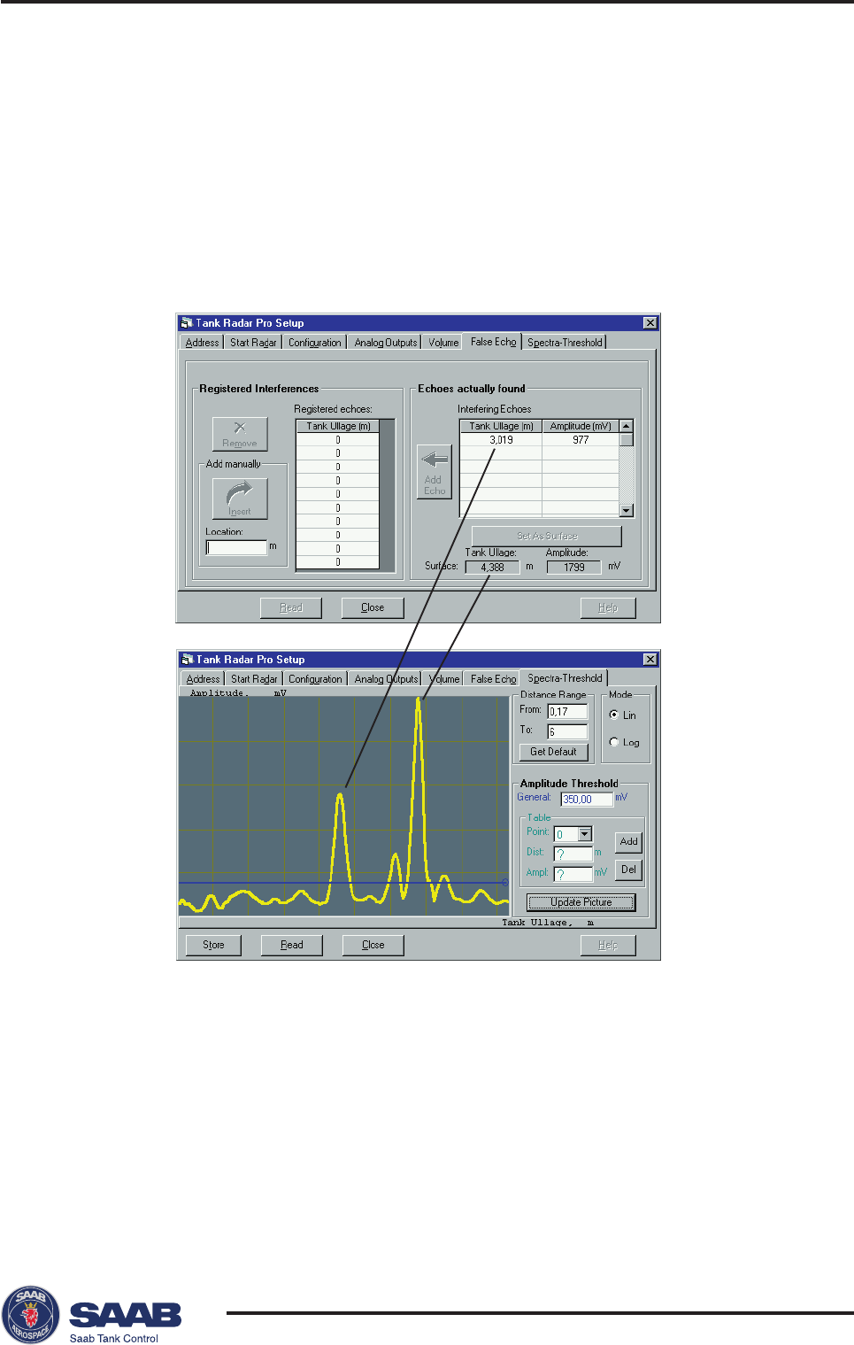
7Disturbance Echo Handling
Pro Setup offers you powerful tools to handle disturbing echoes.
The False Echo tab displays a list of echoes detected by the Pro
transmitter. To optimize measurement performance you can
register false echoes which are due to disturbing objects in the
tank like beams, agitators and heating coils.
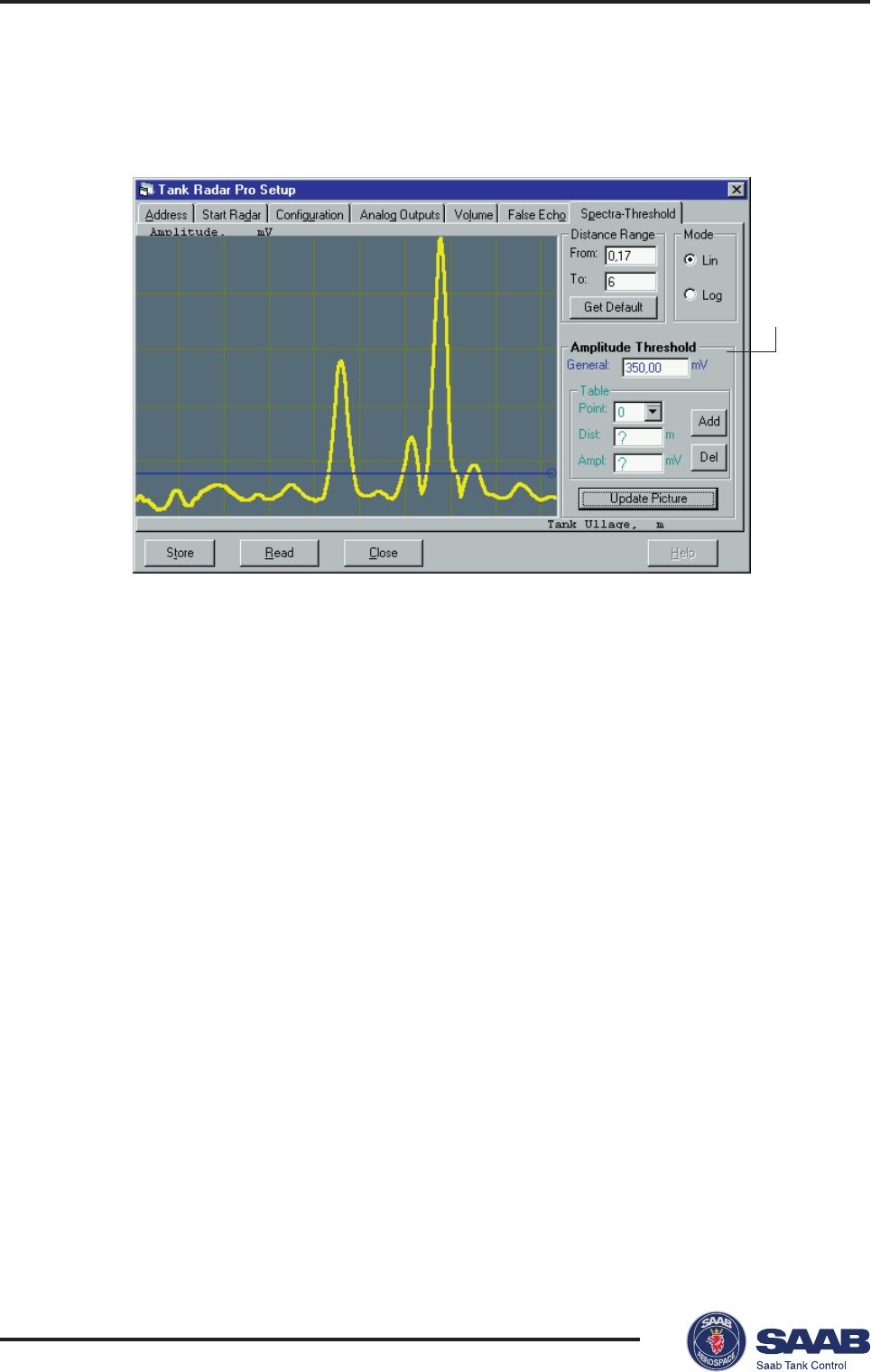
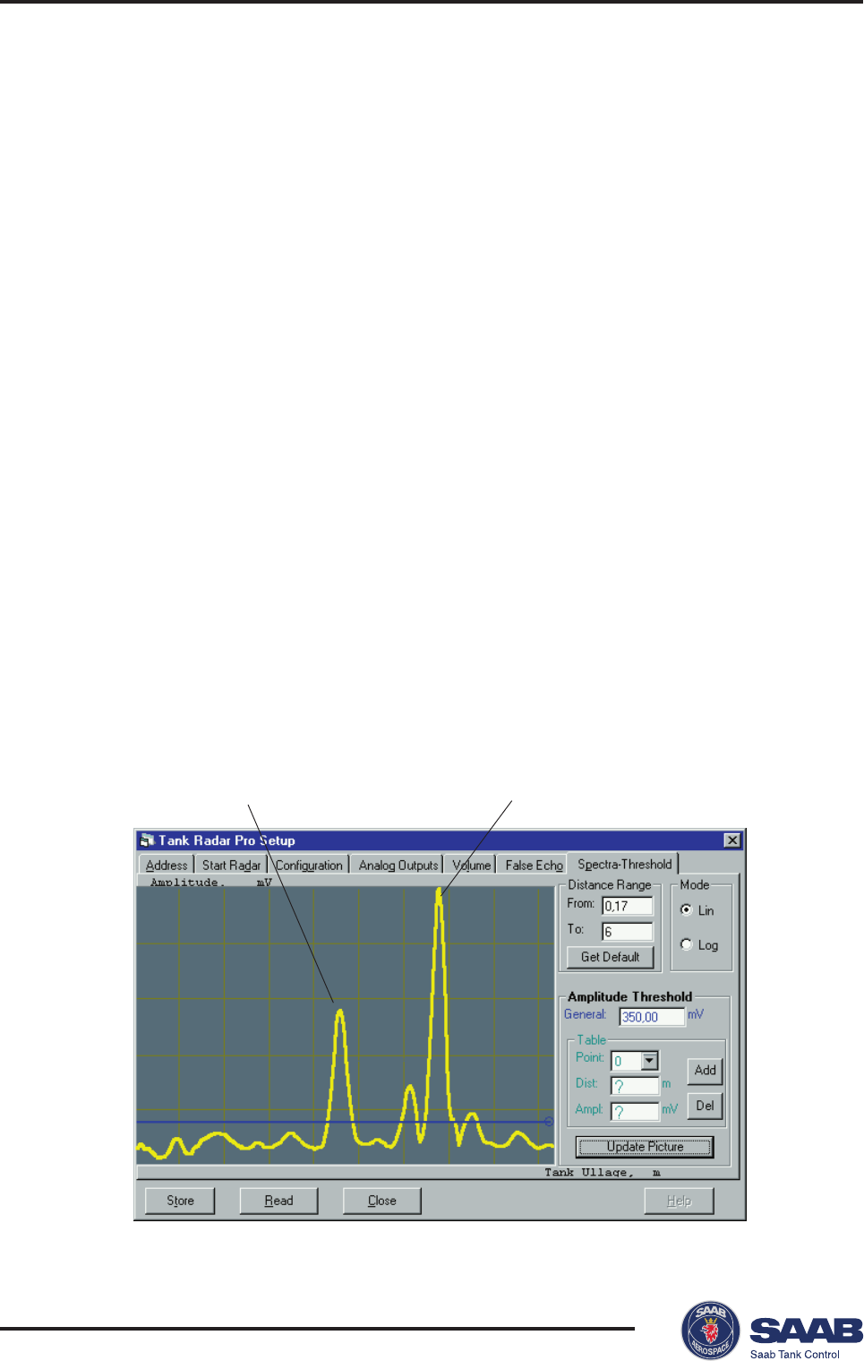
The Spectra-Threshold tab shows the amplitude of the meas-
ured signal along the tank. This diagram is often used to obtain
an overview of the conditions in the tank. You can use this dia-
gram to set a general Amplitude Threshold level in order to
filter out disturbing noise. You can also design an Amplitude
Threshold which is a function of distance from the transmitter
to the tank bottom.
Saab TankRadar® ProPro Setup
4-26
Edition 2. Ref. No: 306010E
Setting a general amplitude threshold
1 Click the
Read
button
Response: a spectrum is displayed showing the radar amplitude vs.
distance from the gauge to the product surface (ullage).
2 Set the general Amplitude Threshold. Echoes with amplitudes
below the general amplitude threshold will be disregarded. Recom-
mended threshold value:
Calm conditions: no turbulence, foam or condensation. Set ampli-
tude threshold to approximately 20% of surface echo amplitude.
Foam, agitators: check amplitude of surface echo when foam is
present or agitator is running. Set amplitude threshold to approxi-
mately 30% of surface echo amplitude.
Note that these figures are approximate estimations. Significant
deviations from these figures may be have to be used in many
cases.
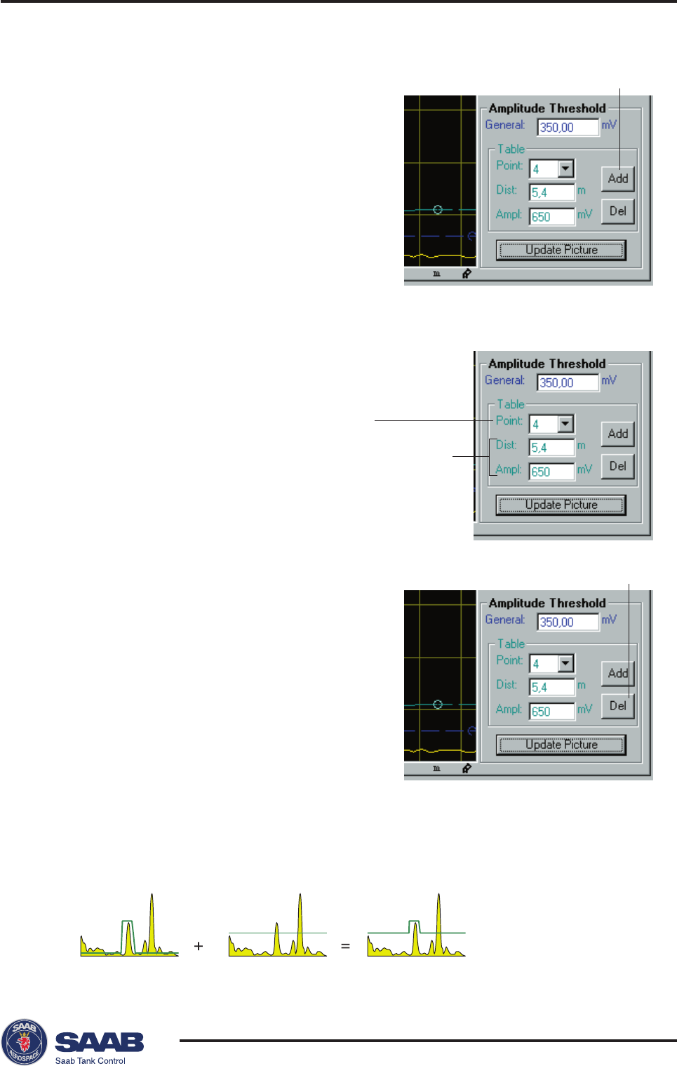
Creating a customized noise threshold table
You can filter out weak disturbing echoes by creating a noise
threshold table. This technique should only be used in special
situations, for example at the bottom of tanks with weak disturbing
echoes. In such tanks the transmitter may lock at disturbances
close to the bottom when the tank is empty. Setting up a noise
threshold in this region will guarantee that the transmitter starts
following the surface when the tank is filled again.
General
amplitude
threshold
Saab TankRadar® Pro Pro Setup
4-27
Edition 2. Ref. No: 306010E
To add points to the diagram:
1 Place the mouse pointer in the diagram
at the position where you want to add a
point to the Amplitude Threshold curve.
2 Click the right-hand mouse button and
select Add point,
- or-
click the Add button in the Spectra-
Threshold window.
Note! The Amplitude Threshold Table
displays the position of the currently
selected point, not the position of the added point.
To move points:
Select the point to be moved and
drag to desired position,
- or -
select the point and specify new
position and amplitude in the Ampli-
tude threshold table.
To remove points:
1 Select the point to be removed.
2 Click the Delete button in the Spectra-
Threshold window.
Do not create noise thresholds around echoes which are already
registered as interfering echoes. The general amplitude threshold
is the lower limit of the noise threshold table:
Selected Point
Position
and
amplitude
Delete button
Add button
Saab TankRadar® ProPro Setup
4-28
Edition 2. Ref. No: 306010E
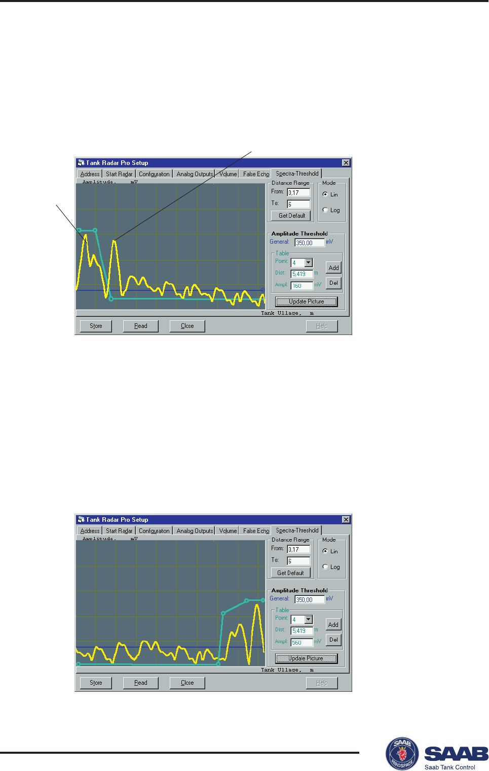
The following examples illustrate how the Amplitude Threshold
table can be used:
Example 1:
The amplitude threshold is used to remove the influence from
the tank nozzle.
Example 2:
In this example the amplitude threshold is used to filter out weak
disturbances close to the tank bottom. By using this technique
the risk of locking to a disturbance echo close to the tank bottom
is eliminated. This technique is particularly useful in tanks with
weak bottom echoes, like e.g. tanks with cone shaped outlets. In
this case you should also make sure that the Tank Presentation/
Bottom_echo_always_visible parameter is not set (see the de-
scription of Start Radar tab).
Influence
from
nozzle
Influence from pipe inside the tank
Saab TankRadar® Pro Pro Setup
4-29
Edition 2. Ref. No: 306010E
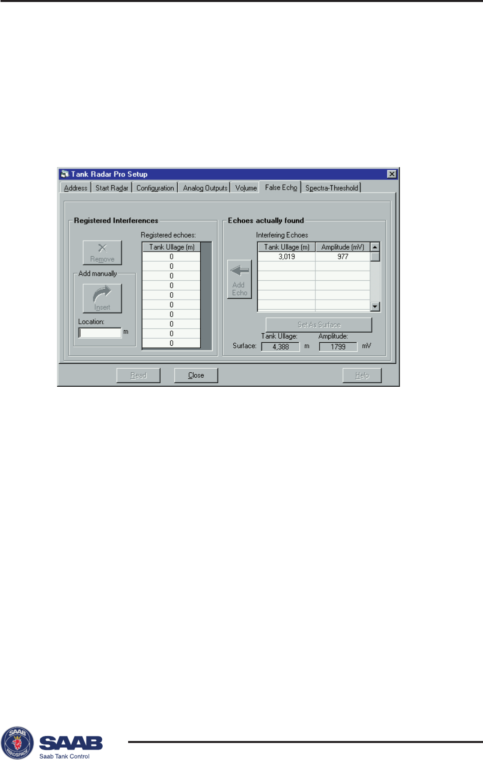
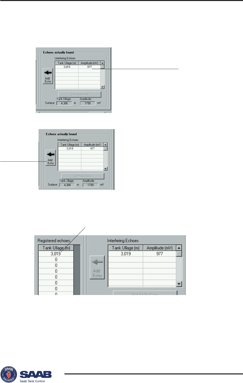
Registration of False Echoes
The False Echo function allows you to let the transmitter register
disturbing echoes caused by objects in the tank. This makes it
possible to detect a product surface close to a disturbance echo
even if the surface echo is weaker than the disturbing echo.
1 Select the False Echo tab
2 Click the Read button to update the list of interfering echoes.
The right-hand list displays disturbances that was detected by the
transmitter. In order to optimize the measurement performance, you
may need to register interfering echoes as described below.
Note! Registration of disturbing echoes requires that Saab´s echofixer is
enabled.
When should I register?
See the following recommendations before you register new interfering
echoes:
• Make sure that a correct amplitude threshold is set before you
register any disturbance echoes. See description of the Spectra-
Threshold window
• Keep the number of registered echoes to a minimum.
• Compare the list of interfering echoes with the tank drawing or by
visible inspection of the tank. Note if there are objects like beams,
heating coils, agitators etc. which correspond to the found echoes.
Only register echoes which can be clearly identified as objects in
the tank.
Saab TankRadar® ProPro Setup
4-30
Edition 2. Ref. No: 306010E
• Make sure that the level is stable before you register a disturbance
echo. A fluctuating level may indicate a temporary disturbance
which is not due to an interfering object.
• Do not register a disturbing echo if the amplitude is below the
general amplitude threshold, see description of the Spectra-Thresh-
old window.
• Do not register a disturbing echo if the amplitude is significantly
smaller than the amplitude of the surface echo when the surface is
at the same level as the disturbance. (In some cases weak disturb-
ing echoes can be filtered out by creating a noise threshold table,
see description of the Spectra-Threshold window).
• It may be necessary to register new disturbance echoes at a later
stage when objects have become visible due to surface movement.
Example 3:
This example illustrates a signal spectrum resulting from a tank
with an agitator. The product level is slightly below the agitator
in this example. In a case like this it is recommended that the
disturbing echo is registered, in order to achieve reliable meas-
urements when the product surface is passing the agitator. Of
course this is true also for disturbing echoes resulting from other
types of objects.
SurfaceAgitator
Saab TankRadar® Pro Pro Setup
4-31
Edition 2. Ref. No: 306010E
Response: the echo is displayed in the table of Registered echoes.
2 Click the Add Echo button.
3 Repeat step 2 until all echoes that you want to register as interfering
echoes (see recommendations on the previous page) are added to
the left-hand table.
4 When you have finished the registration of disturbing echoes, click
the Close button to close the window.
To register interfering echoes do the following:
1 Select an echo from the list of Interfering Echoes.
Echo to be registered
Add Echo
Registered echo

Saab TankRadar® ProPro Setup
4-32
Edition 2. Ref. No: 306010E
To manually add items to the list of registered disturbing echoes
You can manually enter disturbing echoes which are not present in
the list of automatically detected echoes. This function can be
useful if there are objects below the product surface which can not
be detected by the gauge at the time of installation.
To manually add echoes do the following:
1 Enter an ullage value in the Location field. The entered value may
deviate up to 100 mm from the actual position of the object.
2 Click the Insert button.
Using the Set As Surface button
If the transmitter has locked on a disturbing object you can use the
Set As Surface function to point out the surface level. If there is an
echo that you recognize as the product surface rather than an
interfering echo, mark the echo and click the Set As Surface but-
ton.
Saab TankRadar® Pro Pro Setup
4-33
Edition 2. Ref. No: 306010E
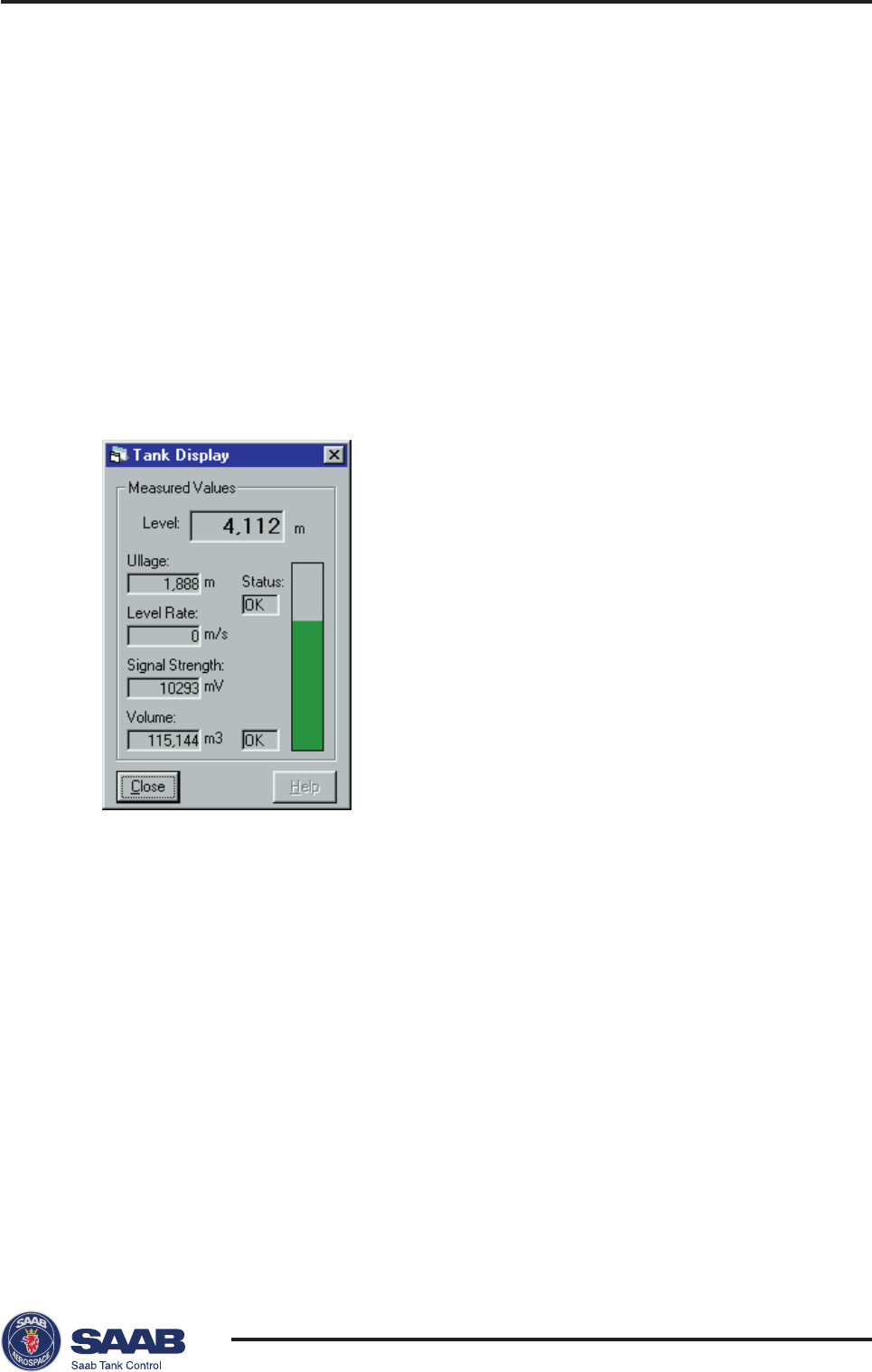
Viewing Level Data
To view level data do the following:
1. Start the Pro Setup program.
2. Open a tank file by choosing Open Tank from the File menu
or
by clicking the Open Tank button.
3. Select the Tank Display option from the View menu,
- or -
click the Display button in the PRO Setup Main window.
The contents of this window is continuously updated. You can change
measurement units by choosing the Measurement Units option from the Setup
menu.

Saab TankRadar® ProPro Setup
4-34
Edition 2. Ref. No: 306010E
Service
The following options are available from the Service menu:
Diagnostics
This option allows you to view the TankRadar Pro status regis-
ters.
Input and Holding Registers
You can view the Input registers as well as the Holding registers
by selecting the corresponding option from the Service menu.
The Holding registers can be edited.
Searching for the Product Surface
Select this option if you want to initiate a search for the product
surface without restarting the transmitter.
Restarting TR Pro
Select this option if you need to restart the TankRadar Pro trans-
mitter.
Saab TankRadar® Pro Pro Display Panel
5-1
Edition 2. Ref. No: 306010E
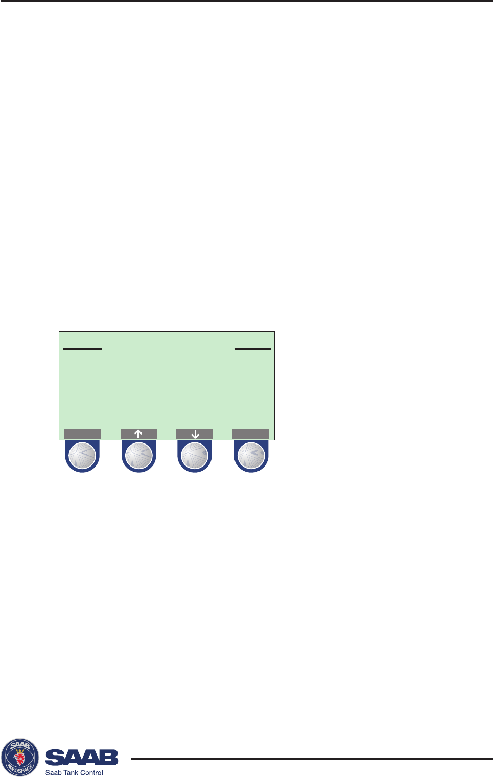
MAIN MENU
View...
Service...
Setup...
NEXT
Operation
You can use the Display Panel (DP) for configuration as well as
for viewing tank data. The four softkeys allow you to navigate
through the different menus, and to select various functions for
service and configuration.
If you leave the DP in Service or Setup mode without pushing
any button for 10 minutes, the DP is automatically switched to
View mode, presenting the same measurement variable that was
displayed last time View mode was open.
The Main menu contains the following options:
5 Using the Pro Display Panel
• The View option allows you to view level data and signal
strength.
• The Service option allows you to view configuration status,
edit holding registers, reset holding registers to factory values,
do a software reset or to start a search for the surface echo.
• The Setup option allows you to configure a TankRadar Pro
transmitter.
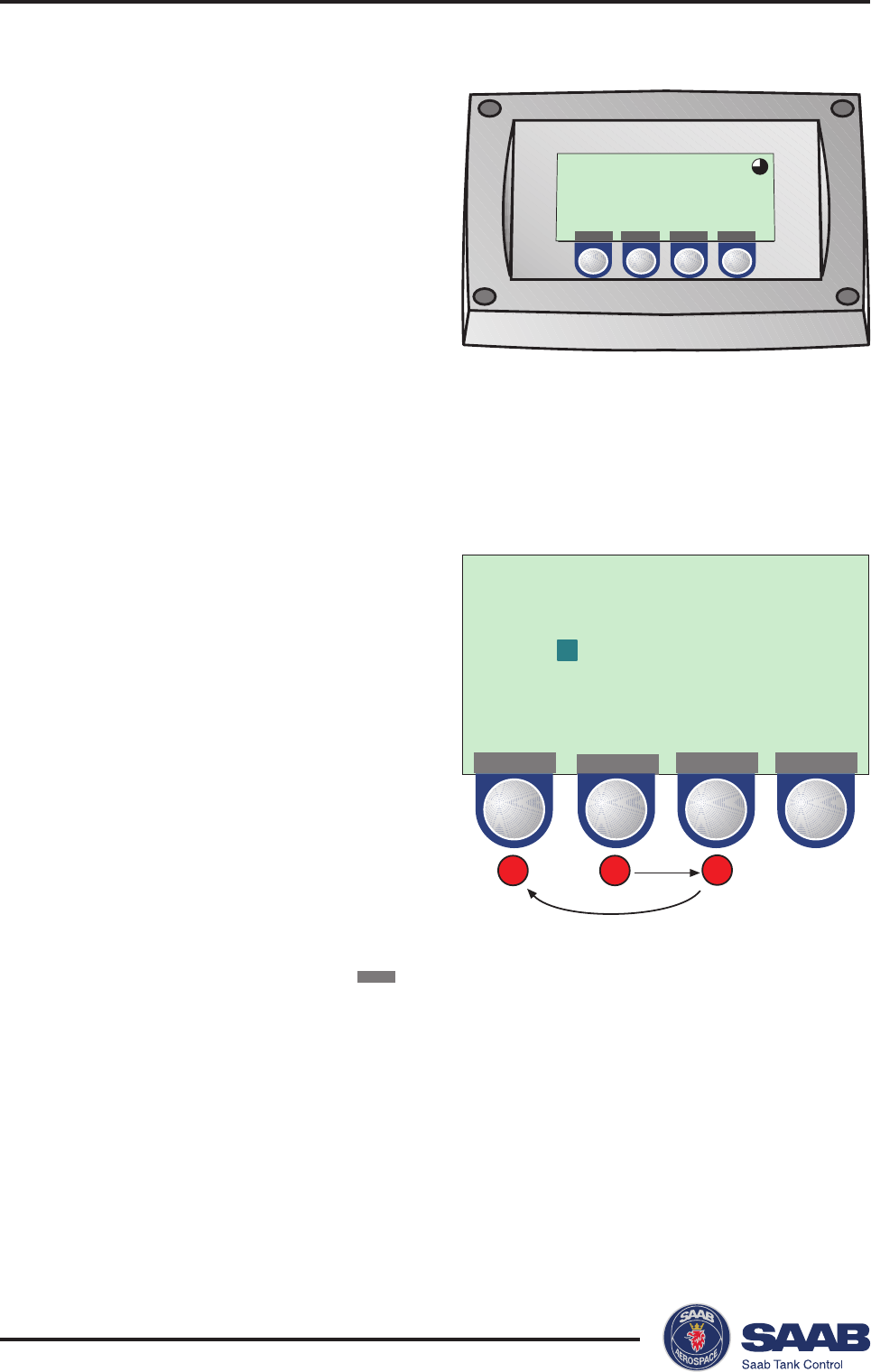
Saab TankRadar® ProPro Display Panel
5-2
Edition 2. Ref. No: 306010E
Give password:
21
"231"
3
**
OK
Level
24.500
MENU ITEM GRPH
m
Adjusting the LCD contrast
The LCD contrast can be
increased by simultaneously
pressing the two buttons on
the right-hand side. Press
the two left-hand buttons to
decrease the contrast. It
takes approximately 10
seconds to adjust from
minimum to maximum display panel contrast.
Entering a Password
Some windows are protected
by a password. The password is
entered by pressing the three
blank softkeys in a certain
order (maximum 12 charac-
ters). Each figure refers to a
particular softkey, as illustrated
below.
As default the password is
blank, i.e. you can open a
password protected window
merely by pressing the
OK
button. In order to use the password protection you have to set
the password as described in Installing a Pro Transmitter/Display
Panel Setup.
If, for example, the password is “231”, you start by pressing the
second key, then the third key and finally the first softkey. You
can change password at any time by opening the Setup/Display
Panel menu.
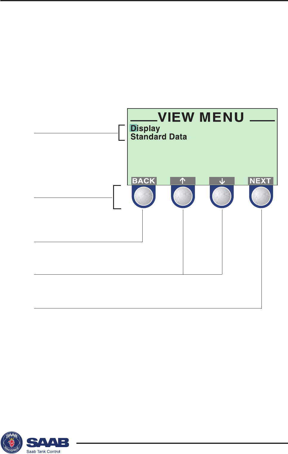
Saab TankRadar® Pro Pro Display Panel
5-3
Edition 2. Ref. No: 306010E
Back to previous menu
Move cursor up/down
Submenus
Softkeys
Open the selected submenu
Softkeys
The softkeys have different meanings depending on which win-
dow that is open. Use the arrow buttons to move the cursor up
and down (or sideways in some windows). These buttons are also
used for changing figures when you are asked to enter a value.
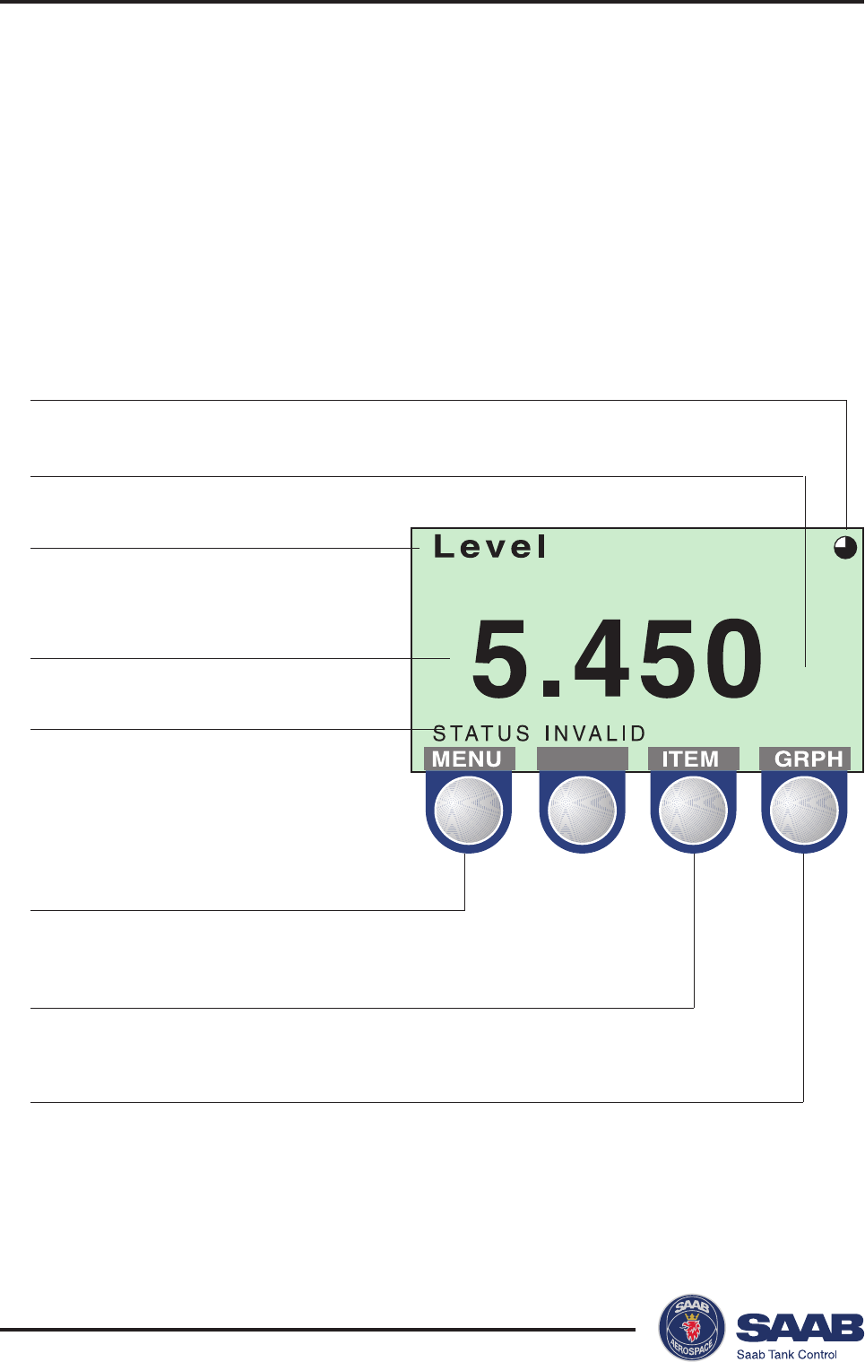
Saab TankRadar® ProPro Display Panel
5-4
Edition 2. Ref. No: 306010E
m
Measurement Indicator
Invalid Data
Measurement Unit
Measured Variable
Measured Value
Back to View Menu
Change Measurement Variable to be Displayed
Change Display Mode
Presentation of measured data
When viewing measurement data, you can use the softkeys to
move between different views as illustrated below. There are also
status indicators showing you that measurements are performed,
and whether these measurements are valid or not.
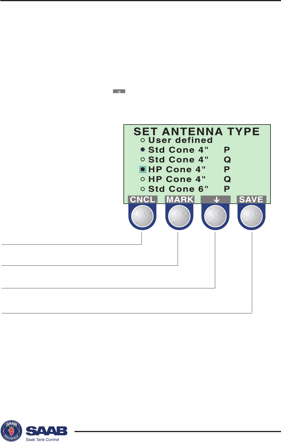
Saab TankRadar® Pro Pro Display Panel
5-5
Edition 2. Ref. No: 306010E
Cancel input and return to
previous menu
Select item at cursor
Move cursor down
Save the current setting
Selecting between different alternatives
When you configure TankRadar Pro, the softkeys will take on
definitions which allow you to select specific items and to save
the choice.
When the cursor has reached the last item, it jumps back to the
first item by pressing the button.
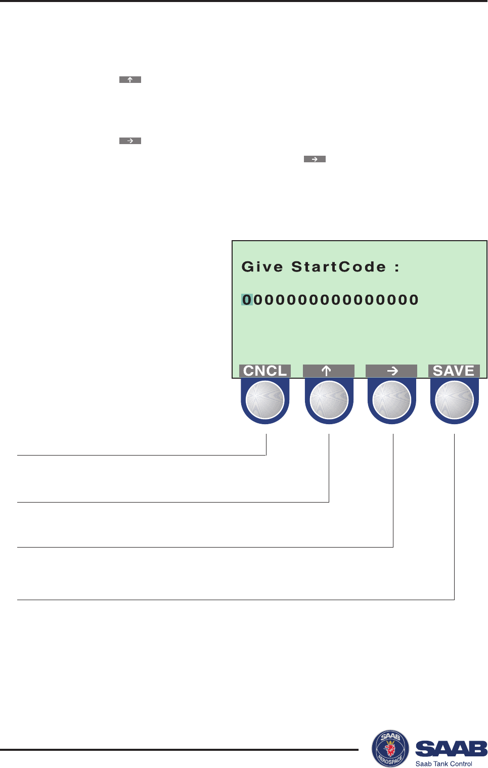
Saab TankRadar® ProPro Display Panel
5-6
Edition 2. Ref. No: 306010E
Cancel input and return to
previous menu
Each click increases the numerical value one step
Each click moves the cursor one step to the right
Save the current setting
Entering numerical values
Use the button to enter the desired value. Each click in-
creases the digit value one step from zero to nine and back to
zero.
Use the button to move the cursor to the next digit. When
the cursor reaches the last digit, select the button to move
back to the first digit again.
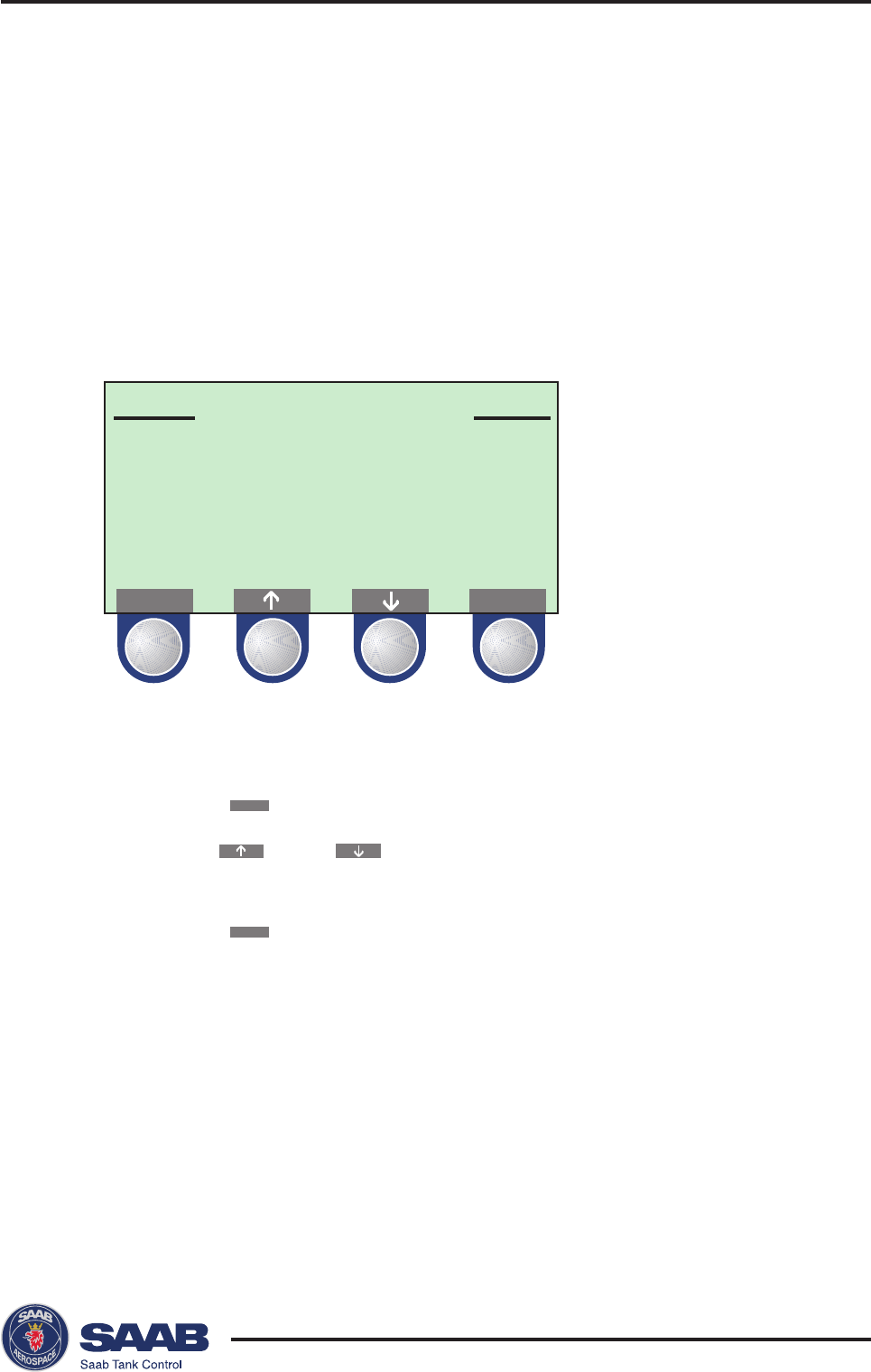
Saab TankRadar® Pro Pro Display Panel
5-7
Edition 2. Ref. No: 306010E
VIEW MENU
Display
Standard Data
NEXTBACK
Viewing Level Data
The View Menu
The View Menu includes options for viewing tank and gauge
related data:
• Press the
BACK
button to return to the Main menu.
• Use the or the button to move the cursor up or
down.
• Press the
NEXT
button to open the selected submenu.
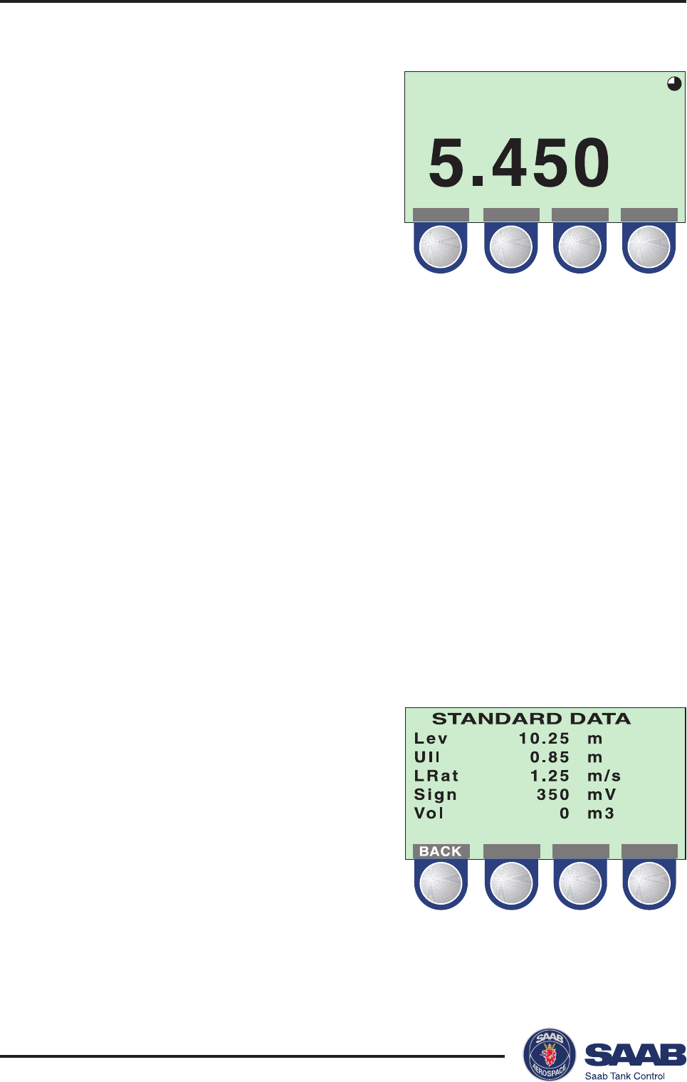
Saab TankRadar® ProPro Display Panel
5-8
Edition 2. Ref. No: 306010E
Level
m
MENU ITEM GRPH
Display
Select the Display submenu to view
measured data:
Press the ITEM button to choose
between the different options:
• Level
• Ullage
• Level Rate
• Volume
• Signal Strength
The GRPH button allows you to switch between display modes:
Numerical measured data is presented as a value.
Bargraph the measured value is presented in a bar
graph showing the current value.
Trend a set of vertical lines are displayed represent-
ing values sampled at a predefined rate. See
Display Panel Setup for descriptions on how to
set up the trend display.
Standard Data
Select the Standard Data option
from the View menu to view a list
of measured variables.
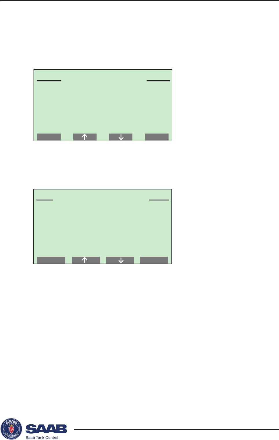
Saab TankRadar® Pro Pro Display Panel
5-9
Edition 2. Ref. No: 306010E
NEXTBACK
SETUP MENU
Display Panel
Guided...
Advanced...
MAIN MENU
View...
Service...
Setup...
NEXT
Installing a Pro Transmitter
Select Setup from the Main Menu and choose one of the options
to configure the transmitter.
The Setup dialog is automatically opened when a transmitter is
started for the first time. You can always return to the Setup
dialog if you want to change settings later on.
Display Panel
This option allows you to set units for measured values, to set
language and to change the user password.
Guided Setup
The Guided Setup option contains the basic steps for configura-
tion of the Pro transmitter.
Advanced Setup
Use the Advanced Setup option if you for example want to in-
clude options for volume calculations and disturbance echo
handling.
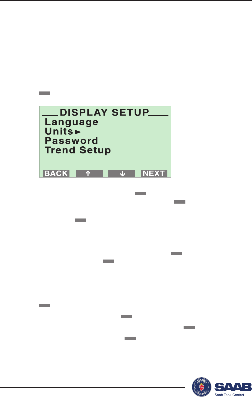
Saab TankRadar® ProPro Display Panel
5-10
Edition 2. Ref. No: 306010E
Display Panel Setup
Use this option to set presentation units, language and password.
If you do not want to change the default settings, you can skip
this step and go to Guided or Advanced Setup.
To configure the display panel do the following:
1. Select the Display Panel option from the Setup Menu and press the
NEXT
button.
2. Select the Units option and press the
NEXT
button. Set the measurement
units to be used for presentation of data and click the
SAVE
button.
3. To change your display panel password select the Password option
and press the
NEXT
button. This password must be entered in order to
be able to change the transmitter configuration. Follow the procedure for
changing to a new password.
4. To set the time scale for trend display (one of the options in the Display
mode) select the Trend Setup option and press the
NEXT
button. Set the
time scale and select the
SAVE
button.
To change language
1. Select the Display Panel option from the Setup Menu and press the
NEXT
button
2. Select Language and press the
NEXT
button.
3. Move the cursor to the preferred language and press the
MARK
button.
4. Save your choice by pressing the
SAVE
button
Response: the display returns to view mode.
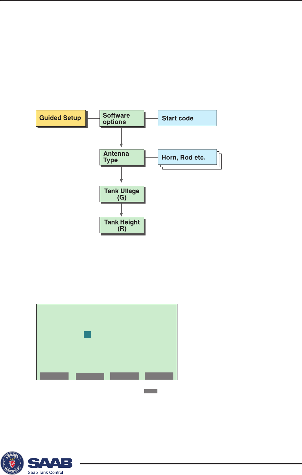
Saab TankRadar® Pro Pro Display Panel
5-11
Edition 2. Ref. No: 306010E
Give password:
**
OK
Guided Setup
The Guided Setup includes the basic steps to start the transmit-
ter.
By using this option you are guided step by step through a se-
quence of configuration windows. The windows are automati-
cally opened in a predefined order.
To configure a new radar gauge using the Guided Setup option
do the following:
1. Choose Setup from the Main Menu.
Response: a request for password is displayed.
2. Enter your password and press the
NEXT
button.
The password is defined by clicking the first three softkeys in a given
order. An asterisk is shown for each key that is pressed. See
Entering a
Password
.
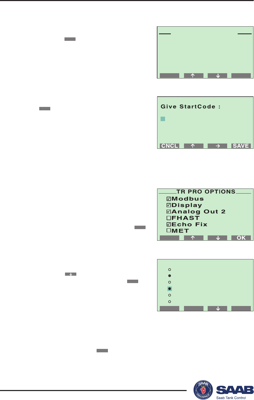
Saab TankRadar® ProPro Display Panel
5-12
Edition 2. Ref. No: 306010E
NEXTBACK
SETUP MENU
Display Panel
Guided...
Advanced...
SAVEMARKCNCL
SET ANTENNA TYPE
User defined
Std Cone 4" P
Std Cone 4" Q
HP Cone 4" P
HP Cone 4" Q
Std Cone 6" P
481A70E9705159F2
3. Select “Guided...” from the Setup Menu and
press the
NEXT
button.
4. Confirm your Start Code by selecting the
SAVE
button.
The transmitter is delivered with a start
code that enables the ordered software
options. If you wish to change the set of
available options, (Saab´s echofixer, Mul-
tiple Echo Tracking™ (MET), Fast High
Accuracy Signal Technique™ (FHAST) and
strapping table volume calculation), contact your local representative for
a new start code.
6. Set the Antenna Type.
Press the button to move the cursor to
the desired antenna, and click the
MARK
button to select it.
HP=high performance (Hastelloy, Tanta-
lum, Titanium, Monel),
Std=standard,
P=PTFE tank sealing,
Q=quartz sealing,
C=Ceramic.
Finish by pressing the
SAVE
button.
5. Note the available software options. (To
see all options use the arrow button to
scroll down the list. Strap table is the last
one).
Go to the next menu by selecting the
OK
button.
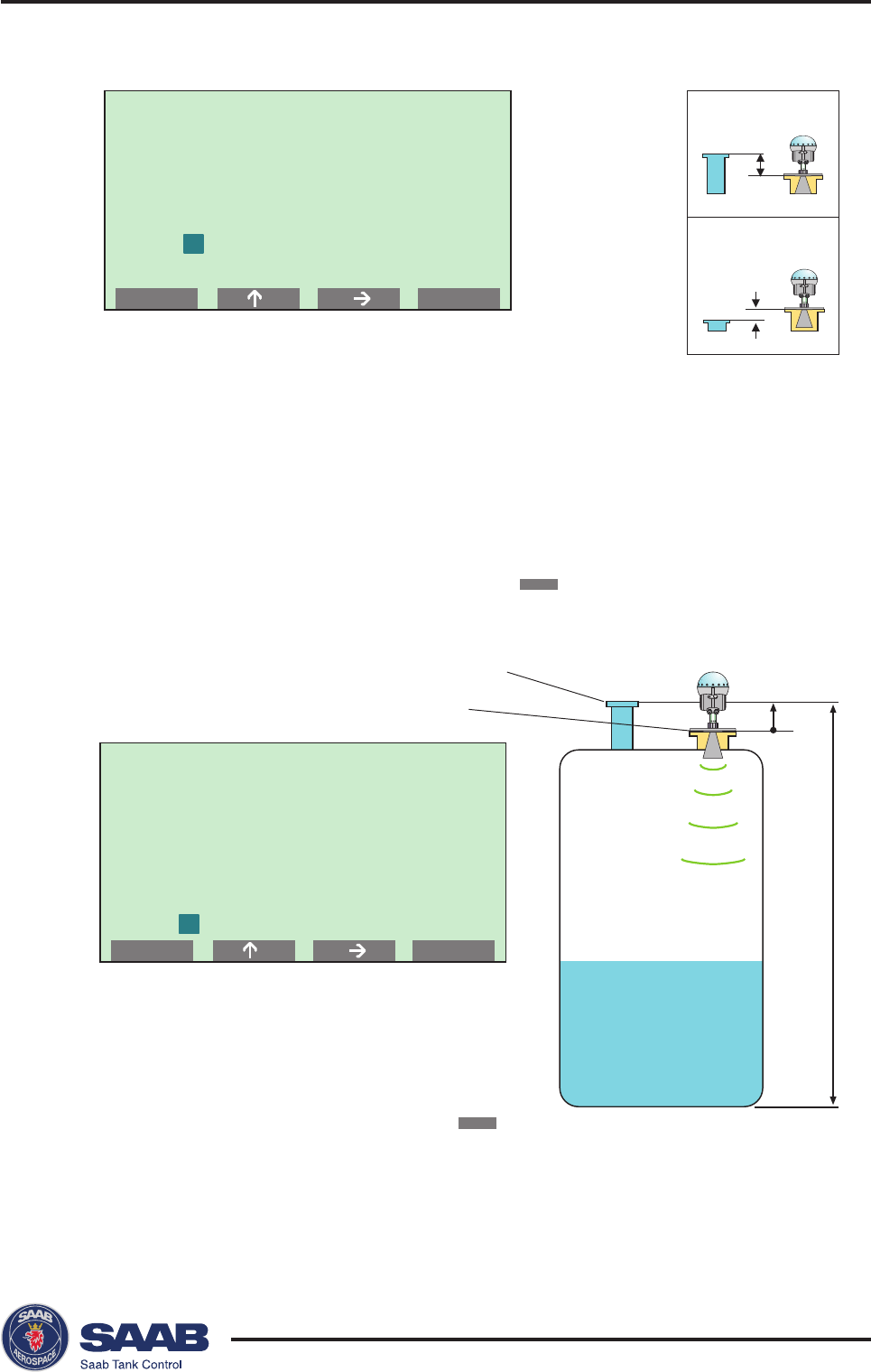
Saab TankRadar® Pro Pro Display Panel
5-13
Edition 2. Ref. No: 306010E
Offset Dist (G)
is the distance
from dipping
mark to TR Pro
ref.point
0.000 m
SAVECNCL
Tank Height (R)
is the distance
from dipping
mark to zero
level ref. point
0.000 m
SAVECNCL
G>0
G<0
G
R
TR Pro Reference Point
Tank Ullage Reference Point
7. Set the Distance Offset (G)
The Distance Offset is defined as the distance between the
upper reference point and the flange
(
the flange is referred to as the
Tank Radar Pro Reference Point)
. You can use G to specify your own
reference point at the top of the tank. Set G=0 if you want the flange as
upper reference point. G is defined as positive if you use an upper
reference point above the
TR Pro Reference Point.
For tanks with an
ullage plug for hand dipping the
Tank Ullage Reference Point (dipping
mark)
can be used as upper reference point, but you can use other
reference points as well. Finish by pressing the
SAVE
button.
8. Calibrate the Tank Height (R).
The Tank Height is defined as the distance
between the upper reference point (specified by
the Distance Offset G) and the lower reference
point (zero level). Finish by pressing the
SAVE
button
Note! See chapter Tank Distances for further information on how to set
the tank geometry parameters.
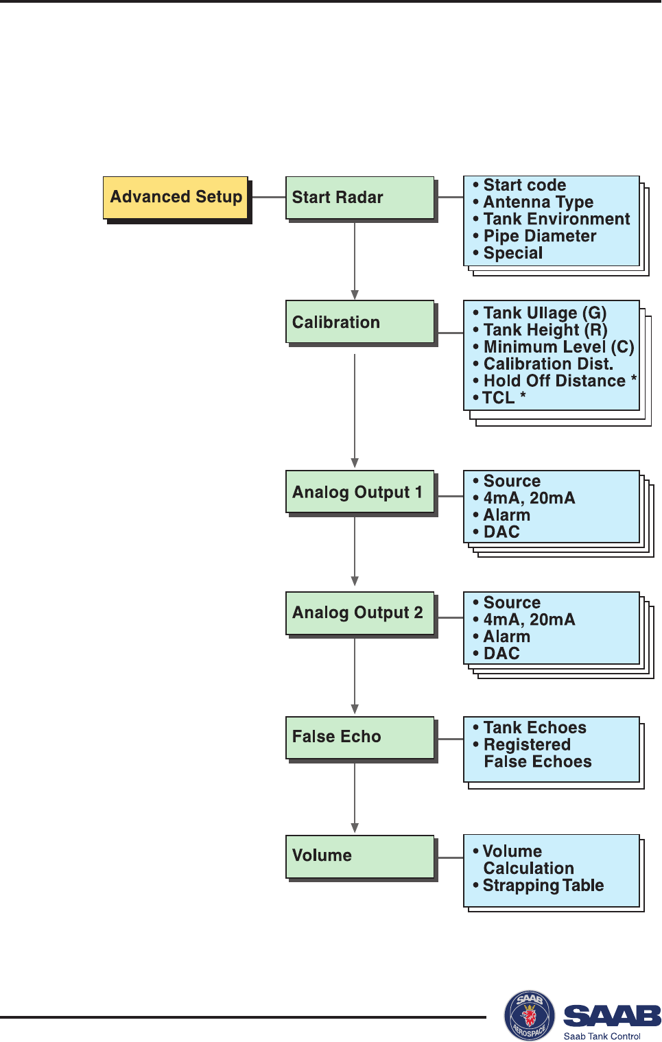
Saab TankRadar® ProPro Display Panel
5-14
Edition 2. Ref. No: 306010E
Advanced Setup
Use the Advanced Setup if you want to make a complete con-
figuration of the transmitter:
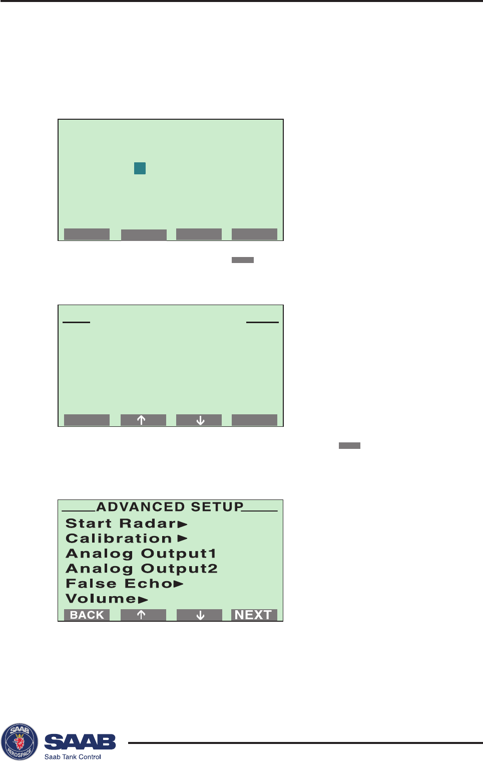
Saab TankRadar® Pro Pro Display Panel
5-15
Edition 2. Ref. No: 306010E
Give password:
**
OK
NEXTBACK
SETUP MENU
Display Panel
Guided...
Advanced...
To configure a radar gauge using the Advanced Setup option:
1. Choose Setup from the Main Menu.
Response: a request for password is displayed.
2. Enter your password and press the
OK
button.
3. Select “Advanced...” from the Setup Menu and press the
NEXT
button.
4. Select the Start Radar option from the Advanced Setup menu.
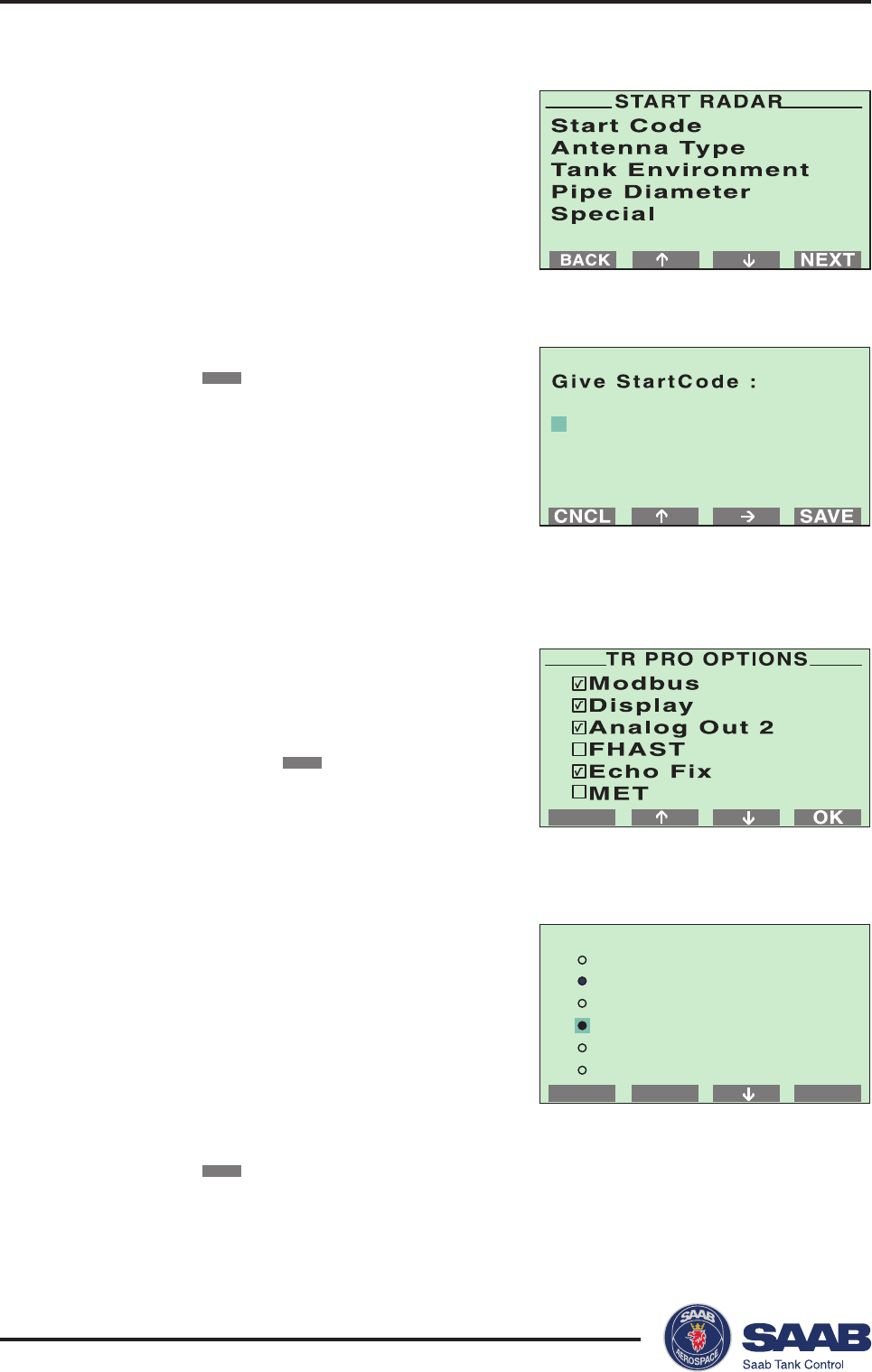
Saab TankRadar® ProPro Display Panel
5-16
Edition 2. Ref. No: 306010E
SAVEMARKCNCL
SET ANTENNA TYPE
User defined
Std Cone 4" P
Std Cone 4" Q
HP Cone 4" P
HP Cone 4" Q
Std Cone 6" P
481A70E9705159F2
1 Choose the Start Code option.
2 Confirm your Start Code by selecting
the
SAVE
button.
The transmitter is delivered with a start
code that enables the ordered software
options. If you wish to change the set of
available options, (Saab´s echofixer,
Multiple Echo Tracking™ (MET), Fast
High Accuracy Signal Technique™
(FHAST) and strapping table volume calculation), contact your local
representative for a new start code
3 Check the list of enabled options.
Contact your local representative if you
like to add one or more software op-
tions. If the list is correct confirm by
pressing the
OK
button.
Response: the Start Radar menu is
opened.
4 Choose the Antenna Type option from
the Start Radar menu.
HP=high performance (Hastelloy,
Tantalum, Titanium, Monel),
Std=standard,
P=PTFE tank sealing,
Q=quartz sealing,
C=Ceramic.
Select the type of antenna that is mounted on the gauge and click
the
SAVE
button.
Response: the Start Radar menu is opened.
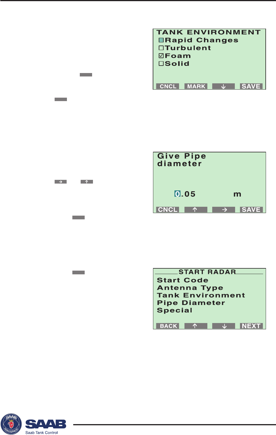
Saab TankRadar® Pro Pro Display Panel
5-17
Edition 2. Ref. No: 306010E
5 Choose the Tank Environment
option.
Select appropriate surface condi-
tions. Mark the options that de-
scribes the conditions in your tank
by using the
MARK
button. You
should not choose more than two
options for best performance. Press
the
SAVE
button to store the current
setting
Response: the display returns to the Start Radar menu.
6 Choose the Pipe Diameter option if
you are using a Still Pipe antenna.
Enter the still pipe diameter by using
the and buttons.
Note that the default value is -0.1
(negative). This means that no pipe
correction is done.
Press the
SAVE
button to store the
entered value.
Response: the Start Radar menu is opened.
7. Press the
BACK
button to return to
the Advanced Setup menu.
The Special option allows you to
make advanced setup of Tank
Environment database registers. For
trained personnel only.
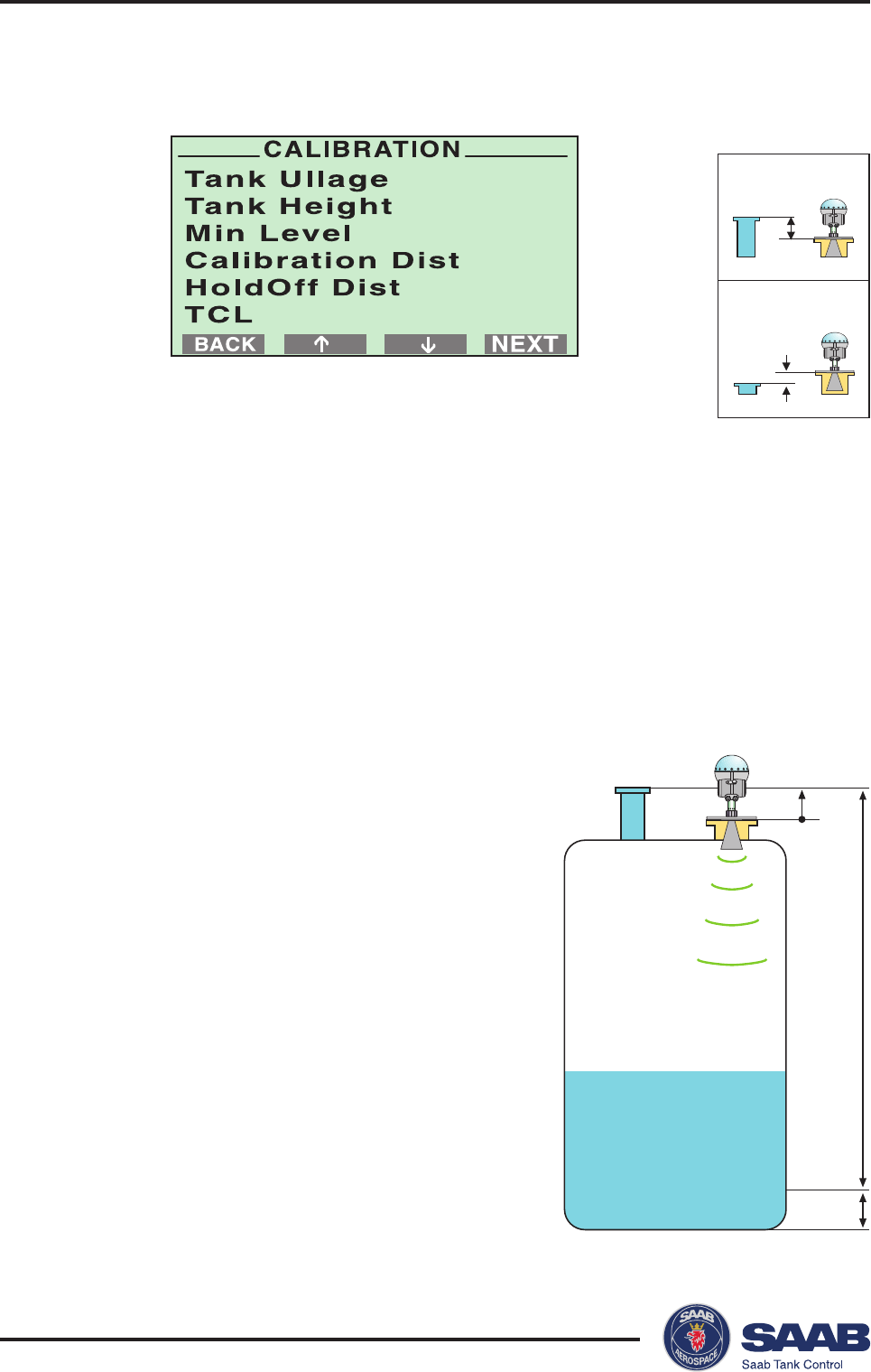
Saab TankRadar® ProPro Display Panel
5-18
Edition 2. Ref. No: 306010E
G
R
C
G>0
G<0
5. Select the Calibration option from the Advanced Setup menu.
The tank calibration distances are defined as illustrated on
the next page.
1 Set the Distance Offset (G).
The Distance Offset is defined as the distance between the upper
reference point and the flange
(
the flange is referred to as the
Tank
Radar Pro Reference Point)
. You can use G to specify your own
reference point at the top of the tank. Set G=0 if you want the flange
as upper reference point. G is defined as positive if you use an
upper reference point above the
TR Pro Reference Point.
For tanks
with an ullage plug for hand dipping the
Tank Ullage Reference
Point (dipping mark)
can be used as upper reference point, but you
can use other reference points as well
2 The Tank Height (R) is defined as the
distance between the upper reference
point (specified by the Distance Offset G)
and the lower reference point (zero level).
3 Set the Minimum Level (C).
The Minimum Level Offset is always
positive and is defined as the distance
between the zero level (
Tank Level Refer-
ence Point
) and the minimum accepted
level. Normally you set the C distance in
order to extend the measurement range to
the tank bottom.
4 Set the Calibration Distance. It should
normally be set to zero but can be used to
compensate for systematic errors due to
e.g. disturbances from the tank nozzle.
This may be the case if the gauge is
mounted in a nozzle which does not
conform to the free space requirements.

Saab TankRadar® Pro Pro Display Panel
5-19
Edition 2. Ref. No: 306010E
Note! See chapter Tank Distances for further information on how to set
the tank geometry parameters.
The following steps are only applicable when a non-standard
antenna is used.
5 Set the Holdoff Distance (H). The Hold Off distance defines how
close to the RTG reference point a level value is accepted. Normally
the Hold Off distance does not need to be changed. However, if
there are disturbing echoes in the upper part of the tank, for ex-
ample from the tank nozzle, you can increase the Hold Off distance
in order to avoid measurements in the region close to the antenna.
6 Set the Tank Connection Length TCL. This value is set automati-
cally when you use one of the standard antennas.
Saab TankRadar® ProPro Display Panel
5-20
Edition 2. Ref. No: 306010E
CONFIG. Aout 1
Source Level
4 mA 0.000 m
20 mA 0.000 m
Alarm HoldLast
D/A Trim...
EDITCNCL
OKCNCL
DA Trim - AOut 1
Setting AOut 1
to 4 mA
6. Select the Analog output1 option from the Advanced Setup menu (Optional).
If the gauge is equipped with an analog output, the range of the
output is automatically calibrated to match the tank calibration (G
and R). If you want to change this setting, do the following:
• Enter Source. Available options are: level, level rate, ullage,
signal strength and volume.
• Enter the analog output values that correspond to 4 mA and 20
mA, respectively.
• Select Alarm mode.
- Select High if you want the analog output to lock on a value
higher than 20 mA when an error is encountered.
- Use Low if you want it to lock on a value below 4 mA.
- The Hold Last option freezes the analog output to the current
value when an alarm is triggered.
•DA Trim. Use this option to calibrate the Digital/Analog Converter
to correspond to the nominal values 4 mA and 20 mA.
Note! The analog output is set to fixed current mode during the
calibration procedure.
To calibrate the DAC do the following:
1 Choose the D/A Trim option.
2 Click the OK button if you want to continue, (or click the CNCL
button to quit without calibrating the D/A converter).
Response: the analog output is set to 4 mA.

Saab TankRadar® Pro Pro Display Panel
5-21
Edition 2. Ref. No: 306010E
DONE
DA Trim - AOut 1
Enter meter
value
4000 µA
3 Enter the measured value that corresponds to the 4 mA setting.
4 Click the DONE button.
Response: the analog output is set to 20 mA.
5 Enter the measured value that corresponds to the 20 mA setting.
6 Click the DONE button.
Now the D/A calibration is finished, and the analog output is no
longer in fixed current mode.
7. Select the Analog output2 option from the Advanced Setup menu (optional).
If the gauge is equipped with an extra analog output, follow the same configuration
procedure as for Analog Output1.
Configuration of the extra analog output is identical to configuration of analog
output 1. See step 6 above.
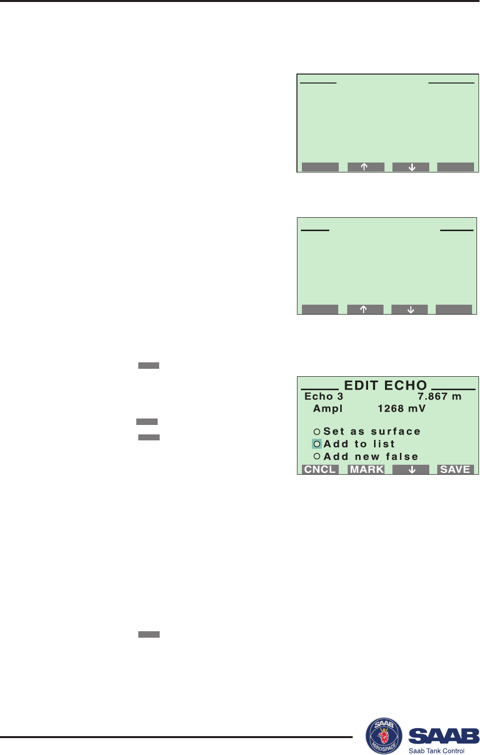
Saab TankRadar® ProPro Display Panel
5-22
Edition 2. Ref. No: 306010E
EDITCNCL
TANK ECHOES
Surface 10.543 m
Echo 1 -0.213 m
Echo 2 1.629 m
Echo 3 7.867 m
Echo 4 20.620 m
Echo 5 21.001 m
Tank Echoes
Reg. False Echoes
FALSE ECHO
BACK NEXT
8. Select the False Echo option from the Advanced Setup menu (optional).
In normal operation the gauge compares
detected echoes with a list of registered
disturbance echoes, in order to decide wich
one is the actual product surface.
To view a list of echoes that the gauge has
detected select the Tank Echoes option.
5 Repeat steps 1 to 4 if you wish to register more disturbing echoes.
The Set as surface option allows you to define an echo as the
product surface.
Mark the Add new false option if you want to manually add echoes.
This may be a useful option if, for example, there are known distur-
bances below the product surface which can not be detected by the
gauge at the time of installation.
6 Click the
CNCL
button to return to the False Echo menu.
To view the current list of registered disturbing echoes select the Reg. False
Echoes option:
You can select echoes from this list and
add to the list of registered echoes. You
should only register disturbing echoes
which can be identified as caused by an
object in the tank. See chapter 5
Pro Setup
Software
for further information on when to
register disturbance echoes.
To register a disturbing echo, do the
following:
1 Move the cursor to the echo you want
to add to the list.
2 Click the
EDIT
button.
3 Move the cursor to Add to list, and
click the
MARK
button.
4 Click the
SAVE
button to register the
marked echo.
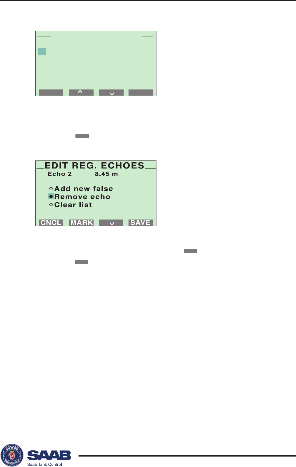
Saab TankRadar® Pro Pro Display Panel
5-23
Edition 2. Ref. No: 306010E
CNCL
1 0.56 m
2 8.45 m
3 14.20 m
4 15.37 m
5 32.00 m
EDIT
REG. FALSE ECHOES
3 Select the Remove echo option and click the
MARK
button.
4 Click the
SAVE
button to remove the selected echo.
Mark the Add new false option if you want to manually add a false
echo to the list of registered disturbing echoes.
Mark the Clear list option if you want to remove the whole list of
registered disturbing echoes. This option may be useful if you want
to create a completely new list.
See chapter 5 Pro Setup Software for further information on
disturbance echo handling. We recommend that the Pro Setup
software is used for configuration of tanks with several distur-
bance echoes.
To remove a registered disturbing echo, do the following:
1 Move the cursor to the echo you want to remove.
2 Click the
EDIT
button.
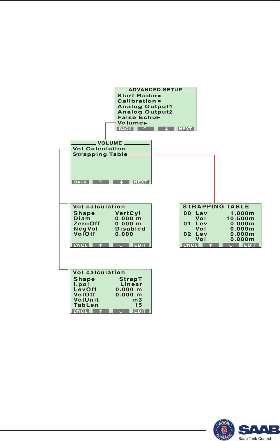
Saab TankRadar® ProPro Display Panel
5-24
Edition 2. Ref. No: 306010E
9. Select the Volume option from the Advanced Setup menu (optional).
The Volume option allows you to setup the Pro transmitter for volume calculations.
You can choose between using either a predefined tank shape like a sphere or a
horizontal or vertical cylinder, or entering level and volume values into a strapping
table
When the configuration is finished you can start viewing meas-
ured data by returning to display mode.

Saab TankRadar® Pro Pro Display Panel
5-25
Edition 2. Ref. No: 306010E
Service
The Service Menu allows you to view the configuration status,
edit holding registers, reset holding registers to factory values, do
a software reset or to start a search for the surface echo. Informa-
tion about antenna type, software versions, operation time, error
status and unit code is available. You can also start a search for
the surface echo and reset some of the holding registers to fac-
tory settings.
The service functions should only be used if you are familiar
with the advanced functionality of TankRadar Pro.
Config Report Shows information on antenna type, software
versions, software and hardware configuration,
operation time, error status and unit code.
Please provide this information if you contact
Saab Tank Control for trouble shooting.
Echo Search Starts a search for the surface echo.
Factory Settings Resets selected holding registers to factory
settings.
Software Reset Use this option to trigger the software start up
procedure.
Super Test Enables all software options (Echofixer, MET,
FHAST, Strap Table) for one week. Use this
option if you want to test options not available
in your transmitter.
Advanced Service Use this option to view input registers and to
view and edit holding registers. The Advanced
Service window is protected by a special
password which is valid for this window only.
Contact your local representative for this
password if you need to use the Advance
Service option.

Saab TankRadar® ProPro Display Panel
5-26
Edition 2. Ref. No: 306010E
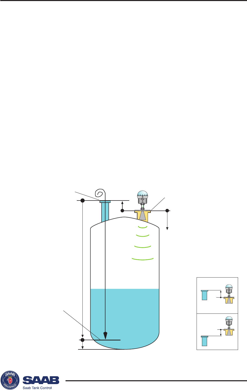
Saab TankRadar® Pro Tank Distances
6-1
Edition 2. Ref. No: 306010E
G
R
C
H
G>0
G<0
6 Tank Distances
Definitions
The Distance Offset (G) is defined as the distance between the
upper reference point and the flange (the flange is referred to as
the Tank Radar Pro Reference Point). You can use G to specify
your own reference point at the top of the tank. Set G=0 if you
want the flange as upper reference point. G is defined as positive
if you use an upper reference point above the TR Pro Reference
Point. For tanks equipped with an ullage plug for hand dipping
the Tank Ullage Reference Point (dipping mark) can be used as
upper reference point, but you can use other reference points as
well.
Tank Ullage
Reference Point Tank Radar Pro
Reference Point
Tank Level
Reference Point

Saab TankRadar® ProTank Distances
6-2
Edition 2. Ref. No: 306010E
The Tank Height (R) is defined as the distance between the
upper reference point (specified by the Distance Offset G) and
the lower reference point (zero level).
If no datum plate or zero level exist the tank bottom usually is
used as zero reference point. In this case C=0.
The Minimum Level Offset (C) is always positive and is defined
as the distance between the zero level (Tank Level Reference Point)
and the minimum accepted level. Normally you set the C dis-
tance in order to extend the measurement below your zero refer-
ence point.
The Hold Off (H) distance defines how close to the TR Pro
reference point a level value is accepted. Normally the Hold Off
distance does not need to be changed. However, if there are
disturbing echoes in the upper part of the tank, for example
from the tank nozzle, you can increase the Hold Off distance in
order to avoid measurements in the region close to the antenna.
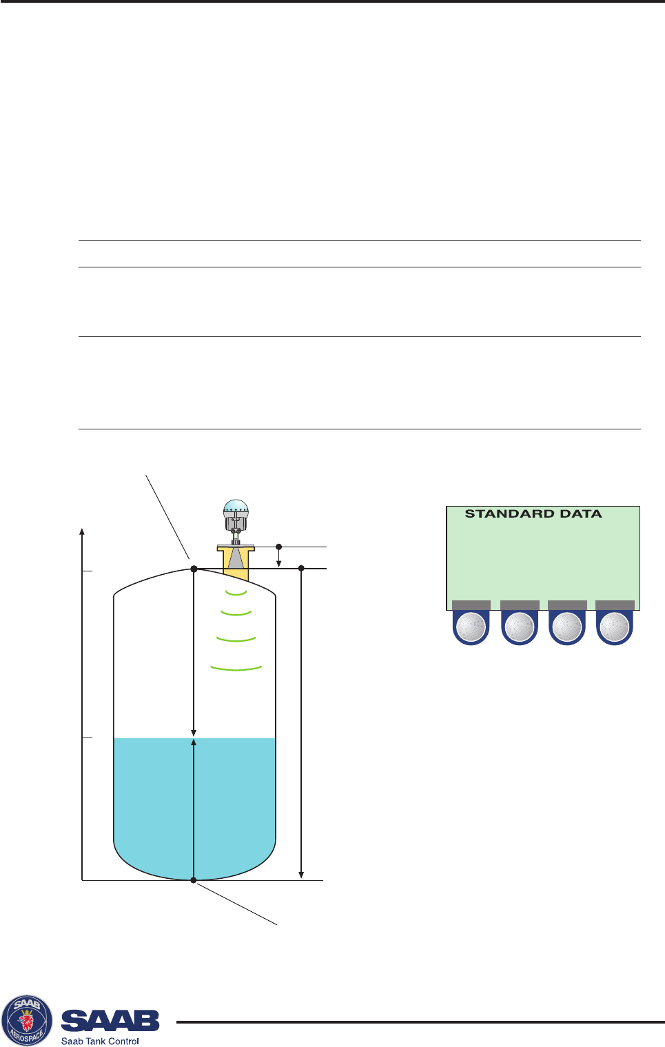
Saab TankRadar® Pro Tank Distances
6-3
Edition 2. Ref. No: 306010E
Lev 4.000 m
Ull 6.000 m
LRat 0.000 m/s
Sign 350 mV
Vol 0 m3
STATUS VALID
BACK
U=ullage
L=level
G=-0.5 m
R=10 m
“0”
U
L
0
4
10
Height (m)
Upper reference point
Lower reference point
Examples
The following examples illustrate how you can set the various
tank distance parameters to suit your own preferred reference
point settings.
Example 1
If you want set
Upper reference point at G=distance between
the tank roof flange and tank roof
(G<0).
Lower reference point at R=distance between upper
the bottom of the tank. reference point and the bottom
of the tank.
C=0.
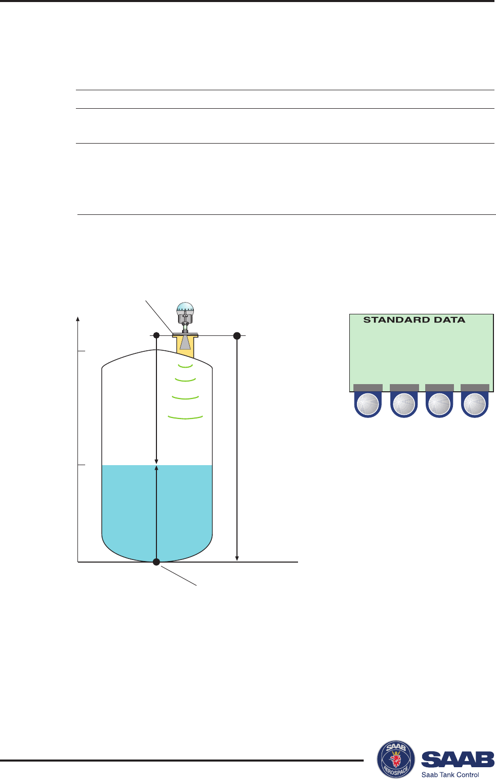
Saab TankRadar® ProTank Distances
6-4
Edition 2. Ref. No: 306010E
Lev 4.000 m
Ull 6.500 m
LRat 0.000 m/s
Sign 350 mV
Vol 0 m3
STATUS VALID
BACK
U=ullage
L=level
G=0
R=10.5 m
“0”
U
L
0
4
Height (m)
10
RTG reference point
(Upper reference point)
Lower reference point
Example 2
If you want set
Upper reference point equal to the G=0
TR Pro reference point
Lower reference point at R=distance between TR Pro
the bottom of the tank reference point and the bottom
of the tank
C=0.
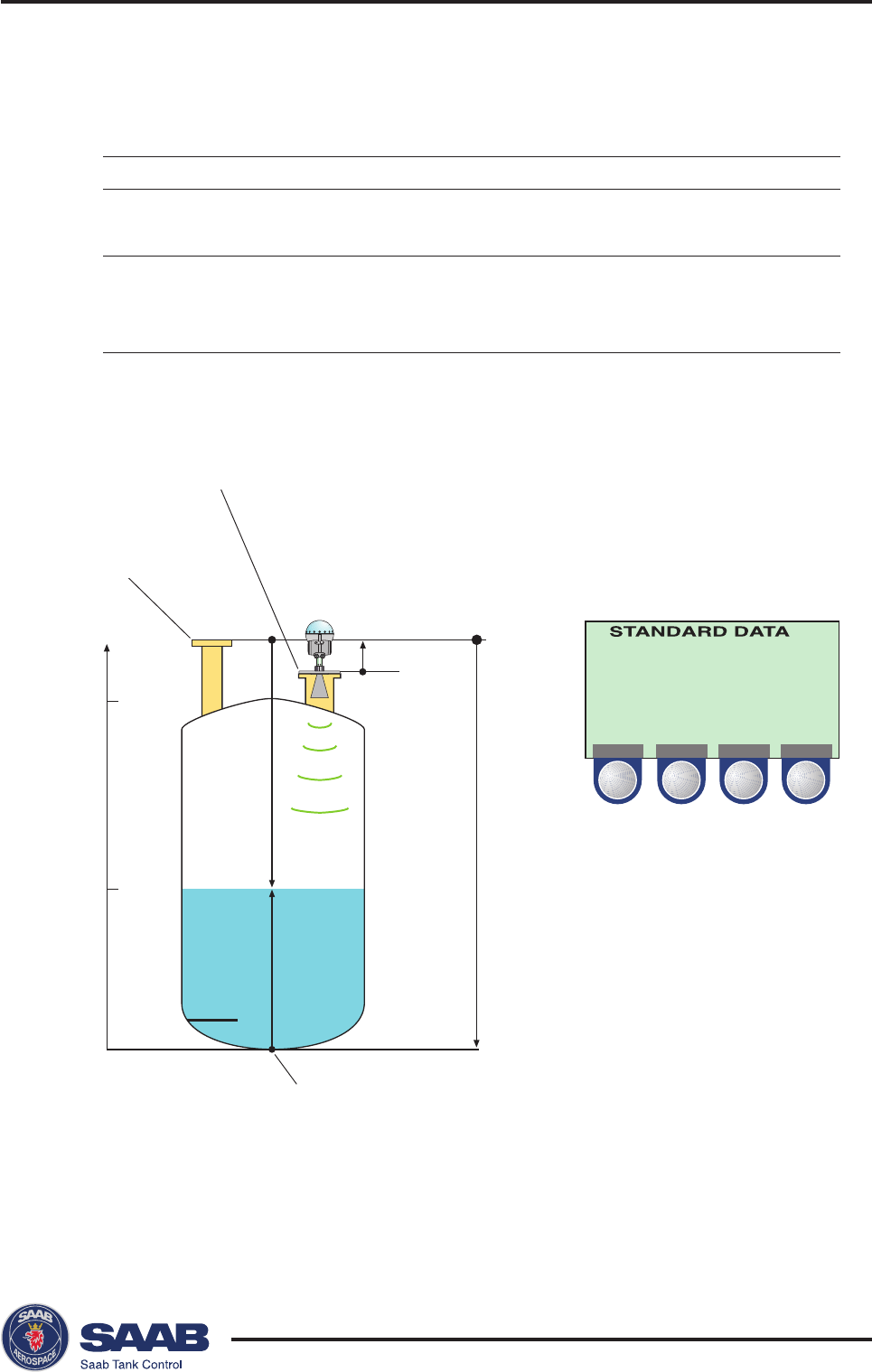
Saab TankRadar® Pro Tank Distances
6-5
Edition 2. Ref. No: 306010E
Lev 4.000 m
Ull 7.000 m
LRat 0.000 m/s
Sign 350 mV
Vol 0 m3
STATUS VALID
BACK
G=0.5 m
R=11 m
“0”
U
L
0
4
Height (m)
10
RTG reference point
Ullage reference point
(Upper reference point)
Lower reference point
Example 3
If you want set
Upper reference point at the G=distance between ullage
ullage reference point and RTG reference points.
Lower reference point at the tank bottom R=distance between ullage
reference point and tank bottom.
C=0.
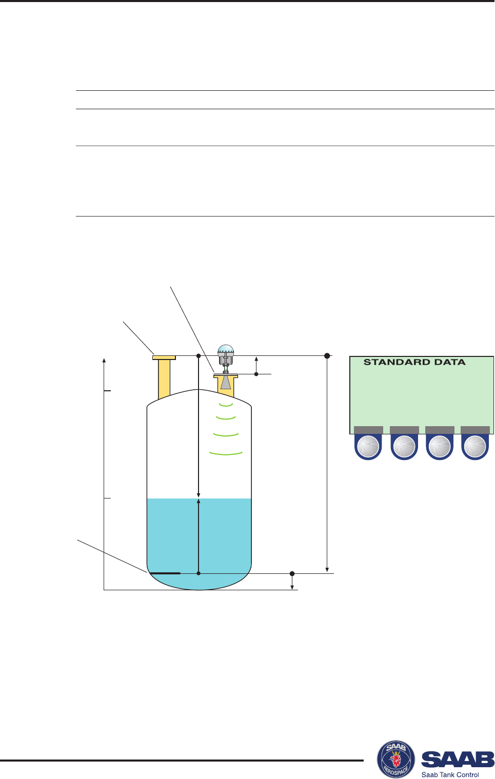
Saab TankRadar® ProTank Distances
6-6
Edition 2. Ref. No: 306010E
Lev 3.800 m
Ull 7.000 m
LRat 0.000 m/s
Sign 350 mV
Vol 0 m3
STATUS VALID
BACK
G=0.5 m
R=10.8 m
“0”
U
L
0.2 m
0
4
Height (m)
10
RTG reference point
Ullage reference point
Datum plate
Example 4
If you want set
Upper reference point G=distance between ullage
at ullage reference point and RTG reference points.
Lower reference point at R=to distance from ullage
datum plate reference point to datum plate.
C=distance between datum
plate and tank bottom.

Saab TankRadar® Pro Technical Information
7-1
Edition 2. Ref. No: 306010E
7 Technical Information
Technical Data
Power supply 100-240 VAC or 24-48 VDC
Power consumption Maximum 15 W
Output cabling Twisted and shielded pair, min. 0.5 mm2
Cable glands EExe approved (CENELEC)
Tank temperature -40-400 °C (-40-750 °F)
Ambient temperature -40-70 °C (-40-158 °F)
Standard measuring range 0-50 m (0-165 ft)
Instrument accuracy ± 5 mm (±0.2”)
Repeatability ±1 mm (±0.04”)
Processors Dual processor design. 32-bit DSP, 50
Mflops
Signal processing FFT, FHAST
Optional disturbance Saab´s Echofixer and
echo handling Multiple Echo Tracking
Level output Display panel, analog 4-20 mA signal with
digital HART, serial Saab TRL/2 Bus
Ex approval Transmitter Head CENELEC:
(Standard and Gold versions) EEx de [ib] IIC T6.
FM:
Explosion proof Class I, Div. I & 2, Groups
A, B, C and D.

Saab TankRadar® ProTechnical Information
7-2
Edition 2. Ref. No: 306010E
Ex approval Transmitter Head CENELEC:
including Display Panel EEx de [ib] ib IIC T4
FM:
Explosion proof/ IS Class I, Div. I & 2,
Groups A, B, C and D
Pressure -1 to 20 Bar (Vacuum to 300 Psi)
Antennas Rod, Cone, Process Seal and Parabola
Antenna materials Teflon®, SS 316L/HC4/Tantalum, Viton/
Kalrez®
Dimensions 545 (H) x 200 (W) mm (4” cone)
Weight 8 kg
Height above flange 400 mm (15”)
Water protection IP 65
Serial communication HART or Saab TRL/2 Bus

Saab TankRadar® Pro Technical Information
7-3
Edition 2. Ref. No: 306010E
Display Panel
• For presentation of measured values and configuration of the
transmitter
• Graphical LCD display 128 x 64 pixels
• Four softkeys
• Text: 7 lines with 16 characters
• Graphics up to 128 X 56 pixels
• Supports service functions
Analog Outputs
Type Galvanically isolated, passive or active
output (external or internal loop supply)
Range 4-20 mA
Alarm level <3.6 mA or >21 mA software selectable
Resolution 0,5 µA (0.003%)
Output impedance > 10 MΩ
Loop resistance < 700 Ω with 24 V external supply
Voltage compliance 7-30 V

Saab TankRadar® ProTechnical Information
7-4
Edition 2. Ref. No: 306010E

Saab TankRadar® Pro Troubleshooting
8-1
Edition 2. Ref. No: 306010E
8 Troubleshooting
SYMPTOM ACTION
No level reading Check the power supply.
Check the cables for serial data commu-
nication.
Incorrect level reading Check the transmitter calibration.
Check that the transmitter has not locked
on an interfering object.
Check that the mechanical installation is
correct.
Serial communication failure Check the COM port setting in the Pro
Setup program.
Check the serial communication address.
Check the cable connections and that the
correct cables are used.
Insufficient power supply to Field Bus
Modem.
Display Panel window is blank Check the power supply
Poor Display Panel contrast Press the two right-hand buttons to in-
crease the LCD contrast.
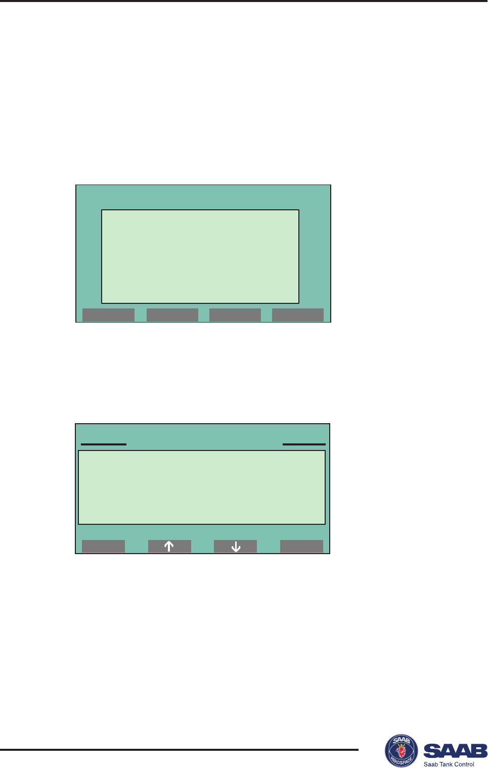
Saab TankRadar® ProTroubleshooting
8-2
Edition 2. Ref. No: 306010E
Display Panel Error Messages
User Input Errors
This message appears if you try to enter an unvalid value into a
holding register.
Internal Software Errors
This message indicates an error in the Display Panel software.
MAIN MENU
View...
Service...
Setup...
ENT
Internal Error
Contact Service
Com failure
Calibrate ullage
by setting the
distance between
dipping mark and
TR Pro ref.point
0.000 m
OK
ERROR
Not a valid
numerical
value

Saab Tank Control Local Representative:
Second edition. September 1998.
Ref. nr. 306010 E.
Saab Tank Control
Box 13045
S-402 51 Göteborg
SWEDEN
Phone: + 46 31 337 00 00
Fax: + 46 31 25 30 22
e-mail: sales.stc@marine.combitech.se
Internet: http://www.saab.tankradar.com