Rosemount Tank Radar REX Radar Level Gauge User Manual Installation manual
Rosemount Tank Radar AB Radar Level Gauge Installation manual
UserManual.wiki
>
Rosemount Tank Radar
>
REX User Manual
Installation manual
Navigation menu
Upload a User Manual
Namespaces
Wiki Guide
HTML
PDF
Info
Views
User Manual
Discussion / Help
Navigation

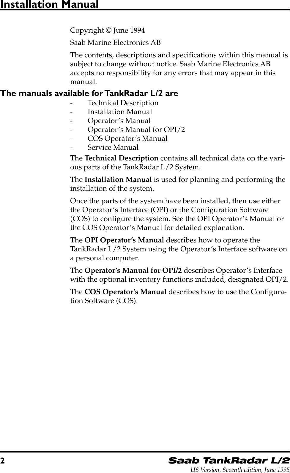
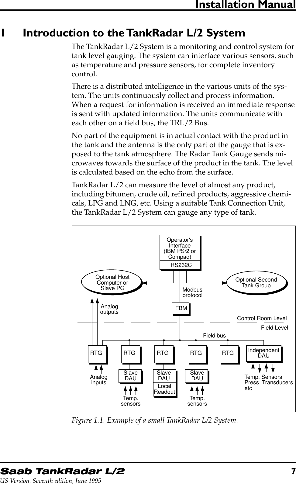
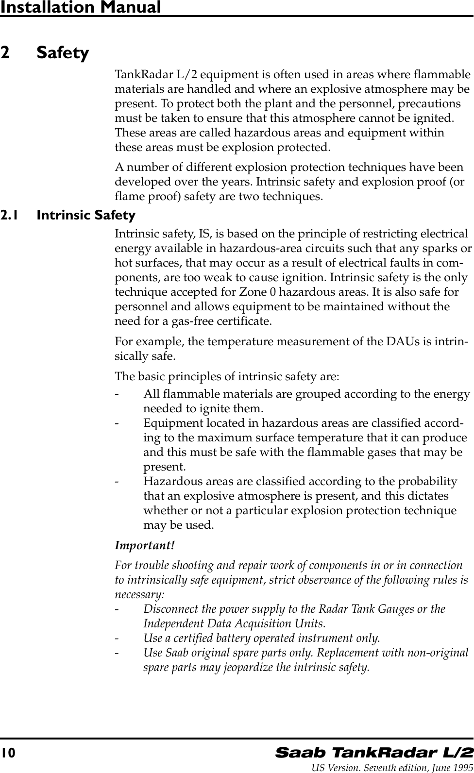
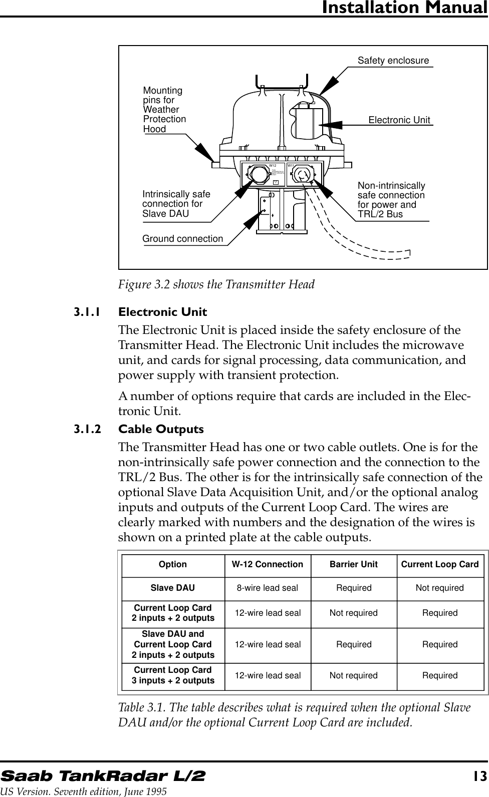
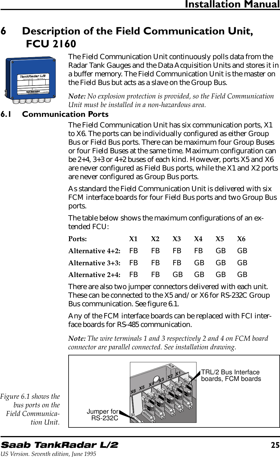
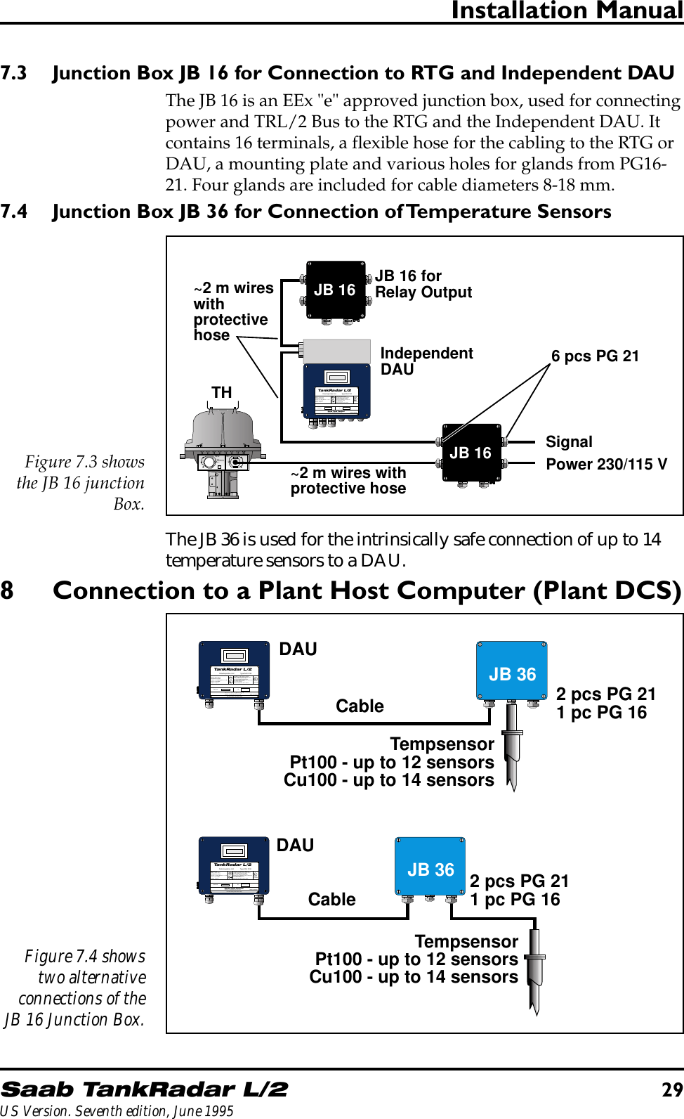
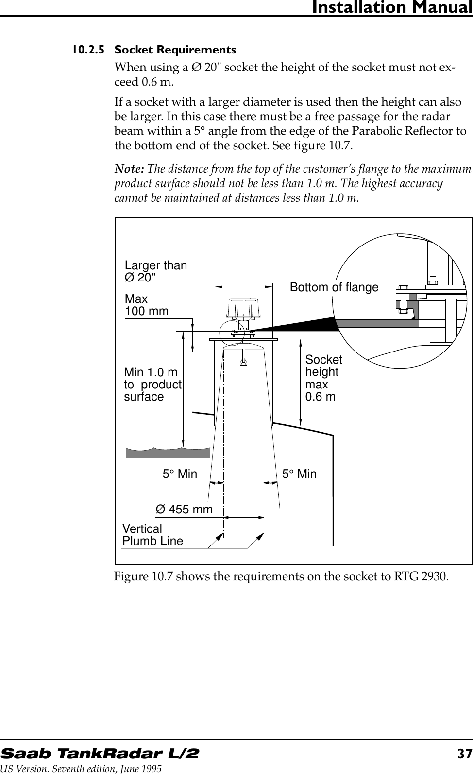
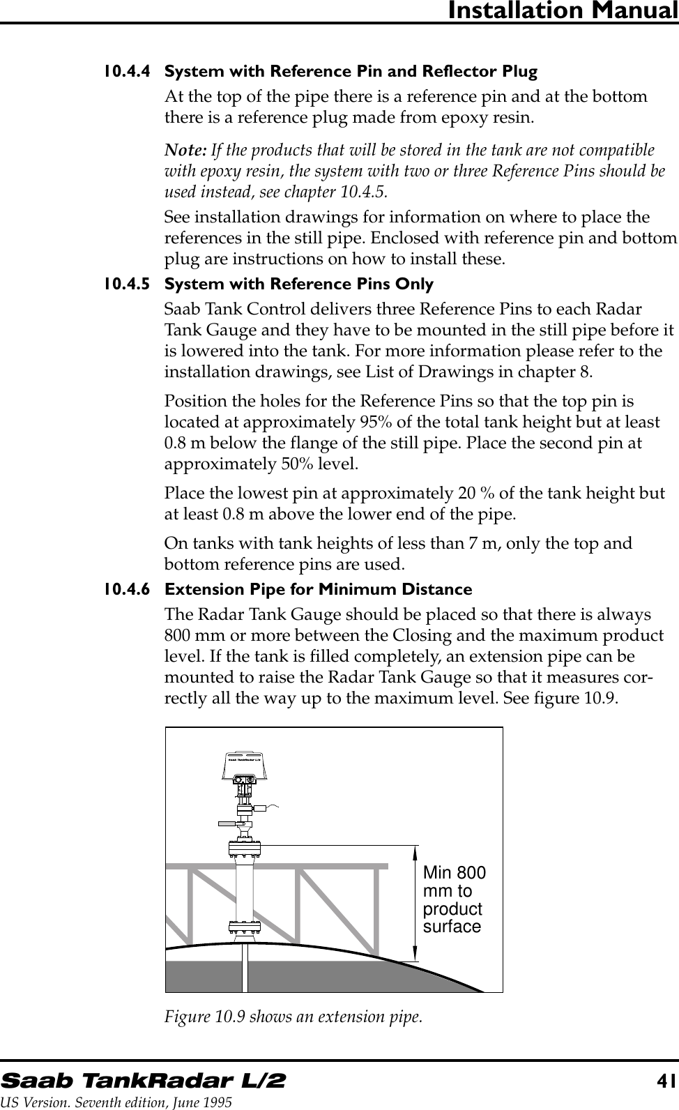
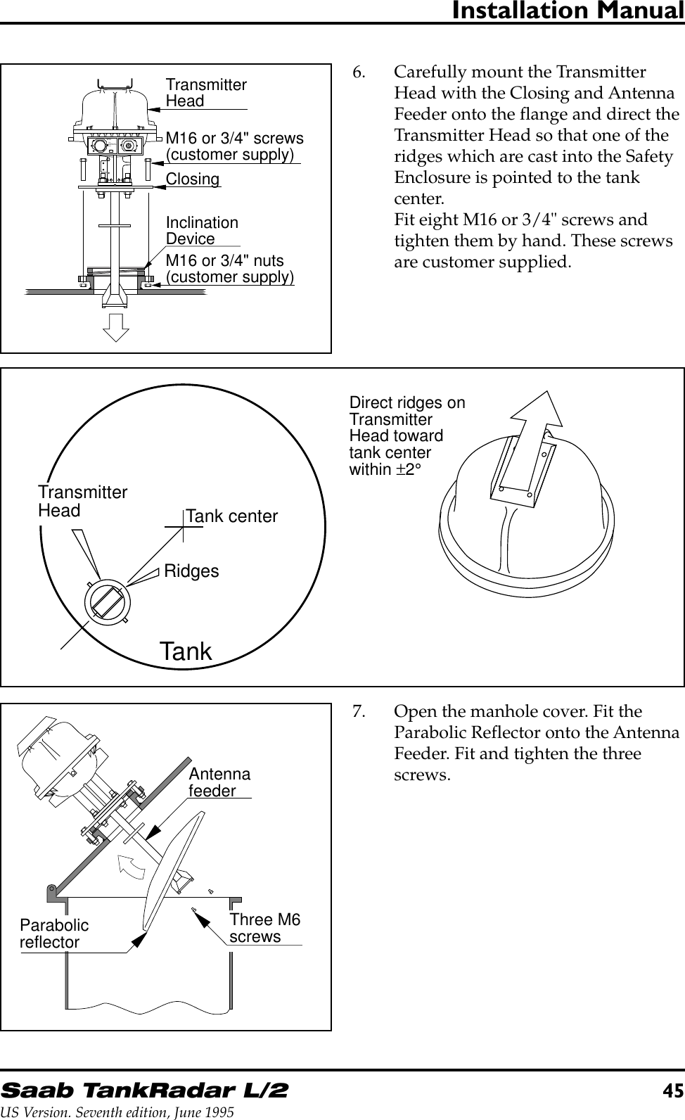
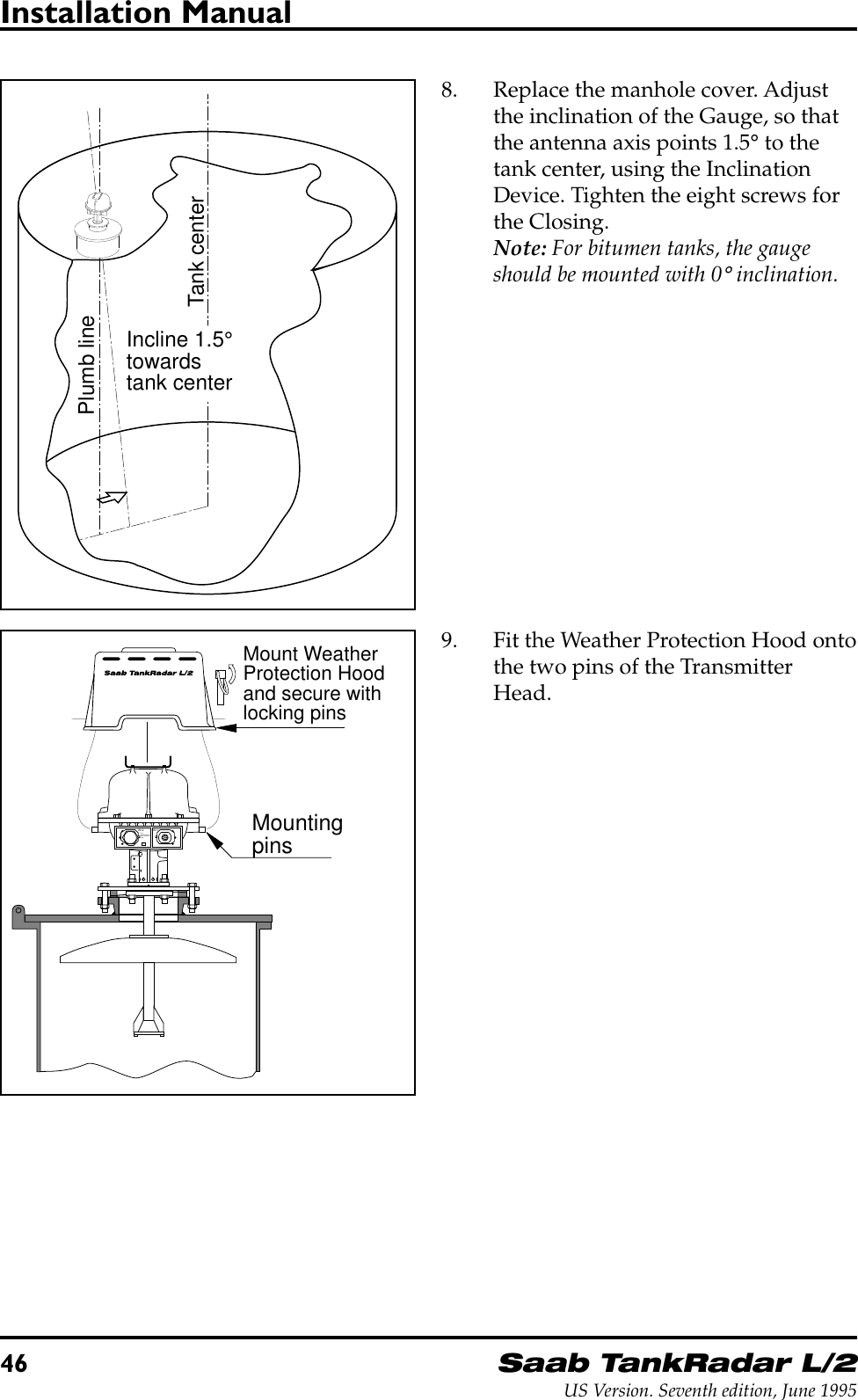
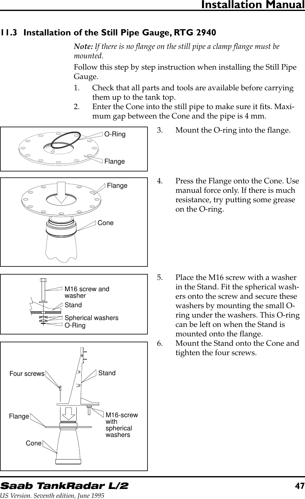
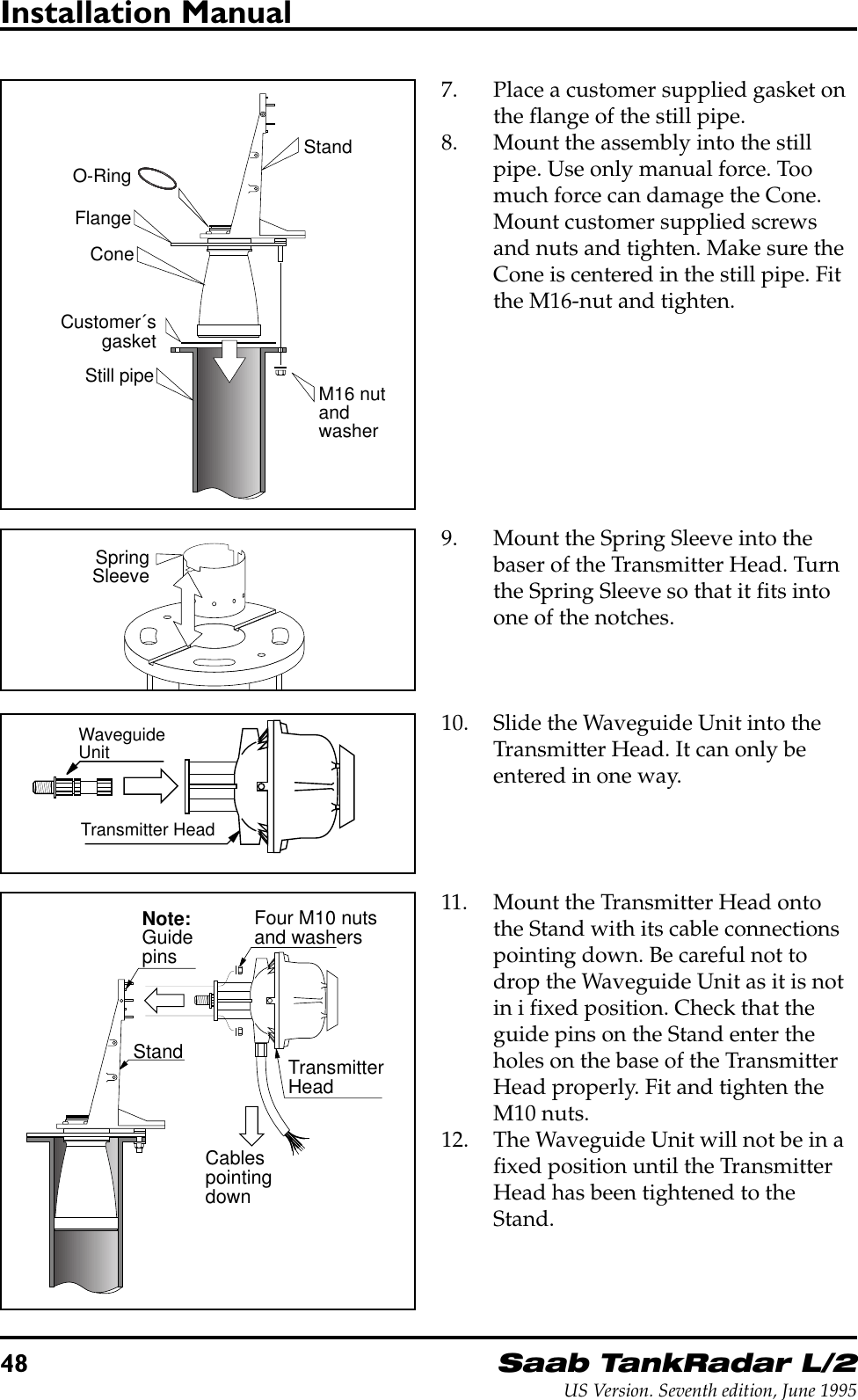
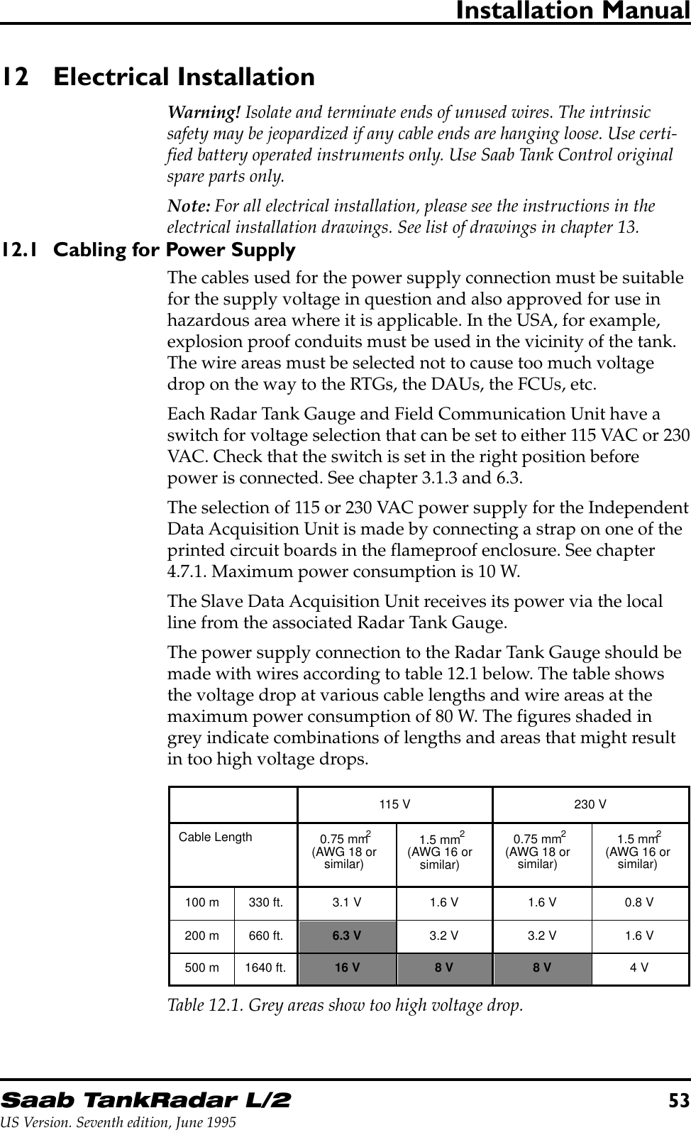
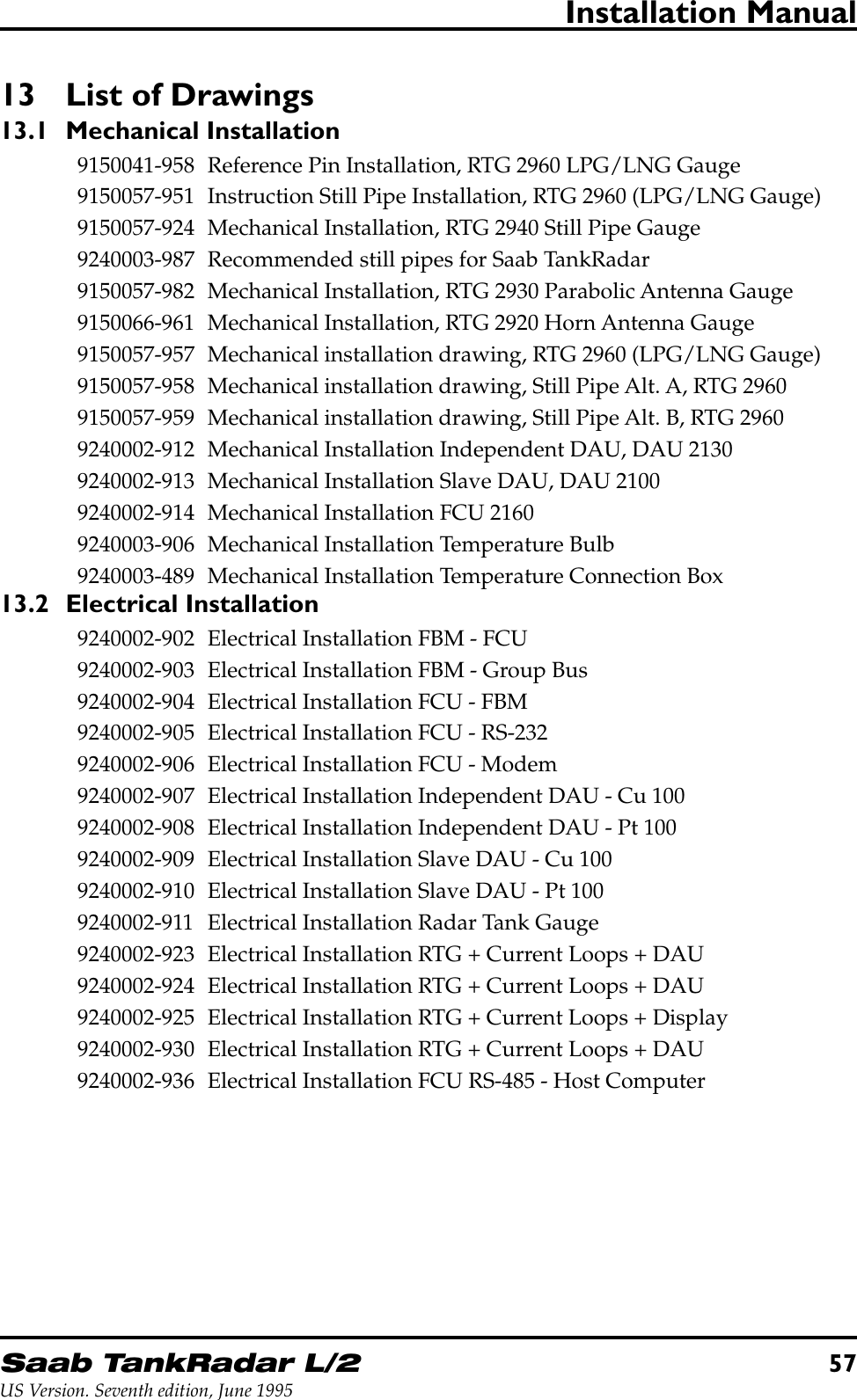
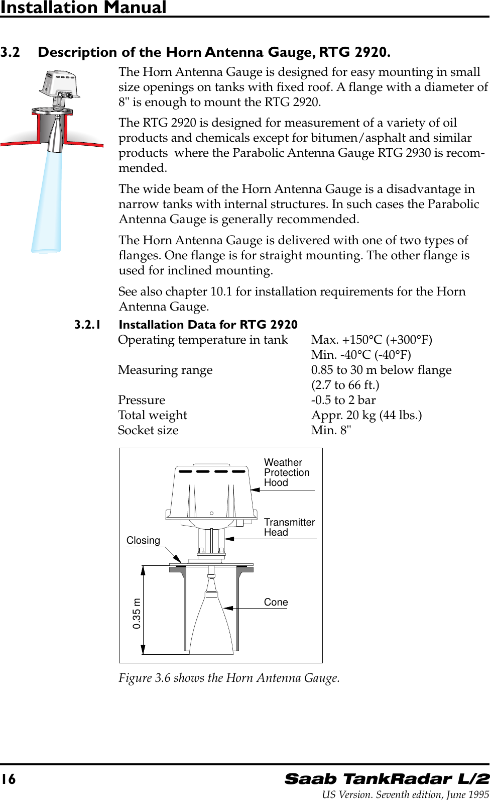
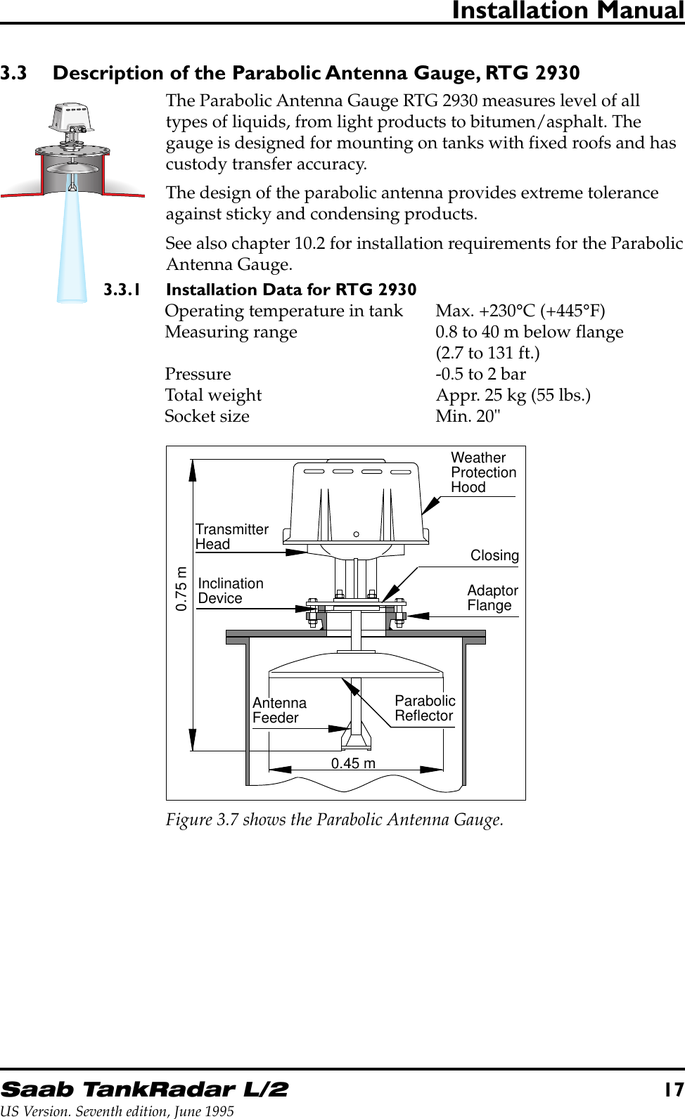
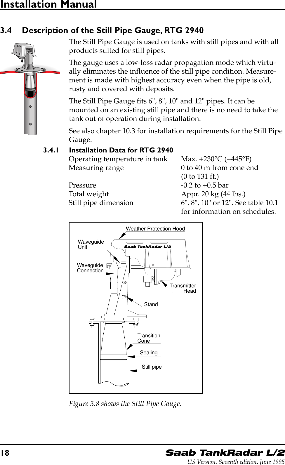
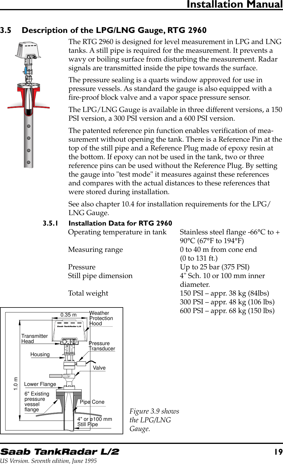
![14Saab TankRadar L/2US Version. Seventh edition, June 1995Installation Manual3.1.3 Power Supply to the Radar Tank GaugeThere is a switch on the Electronic Unit for setting of the powersupply to 115 V or 230 V. As standard the switch is set to 230 V.To select supply voltage, remove the cover of the Safety Enclosureand set the switch on the Electronic Unit to either 115 V or 230 V.See figure 3.3Figure 3.3.Note: Do not turnthe switch all theway around as itmay damage theswitch.MAINS VOLTAGE SELECTOR115V/230VSELECTED VOLTAGE TOBE MARKED ON OUTSIDENAMEPLATE230 V115 VMains wired for 230 VAC 0.4AMark Box if re-wired for 115 VAC 0.8ASelector inside enclosure.Serial no: UI:CAUTION: To prevent ignition of hazardousatmospheres, disconnect the device from thesupply circuit before opening. Keep assemblyclosed when in operation.Do not open while enrgized.Ne pas ouvrir sous tension.Hazardous Location Class IGroup C and D. (Intrinsically Safeoutputs Group A,B,C and D)Temperature Coide T4.Leads factory sealed. The deviceprovides intrinsically safe outputsSee control drawing 9150057-901Ambient temperature -40 to + 65°CBox marked when this enclosurecontains Associated ElectricalApparatus. Component Certificate BAS Ex91C2065U coded [EExia]IIC BAS Ex93C2043U coded [EExia]IIBEEx dIIB T4 T amb = -40 to +65°CBASEEFA Ex91C1065XRadar Unit Type TH 2000ExA division of Saab Marine Electronics ABMADE IN SWEDENLISTED 939UMains wired for 230 VAC 0.4AMark Box if re-wired for 115 VAC 0.8ASelector inside enclosure.Serial no: UI:CAUTION: To prevent ignition of hazardousatmospheres disconnect the device from thW11W12FORINTRINSICALLYSAFE CIRCUITSONLY"i"RTGnameplateMark the box on theRTG name plate if thepower setting has beenchanged to 115 VAC.RTGFigure 3.4.Note: On the labelon top of the Trans-mitter Head, there isa box that must bemarked with an "X"if you set the switchto 115 V. See figure3.3. Always checkthis label beforeconnecting power tothe Electronic Unit.3.1.4 Barrier Unit Card, BU (Option)The optional Barrier Unit Card is used when a Slave Data Acquisi-tion Unit is connected to a Radar Tank Gauge. It provides intrinsi-cally safe power and communication between the Slave DAU andthe RTG. The Barrier Unit is installed inside the Transmitter Head.The Barrier Unit is connected to the Slave DAU through the Intrin-sically Safe Connection W12 on the Radar Tank Gauge.Note: Installation of the Barrier Unit Kit, the Current Loop Card or theMetrological Seal may only be done by personnel from Saab Tank Con-trol.](https://usermanual.wiki/Rosemount-Tank-Radar/REX/User-Guide-28351-Page-14.png)
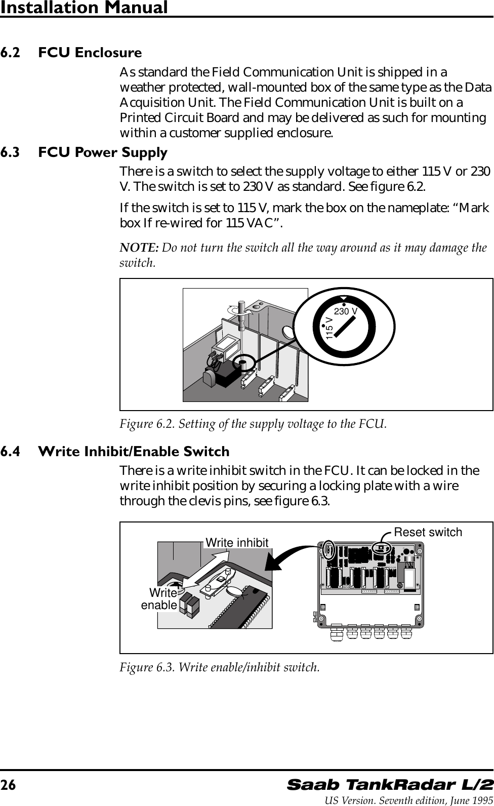
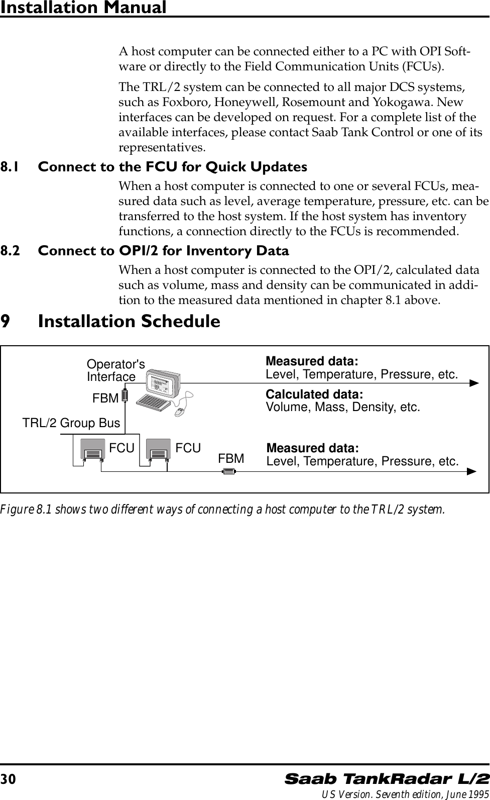
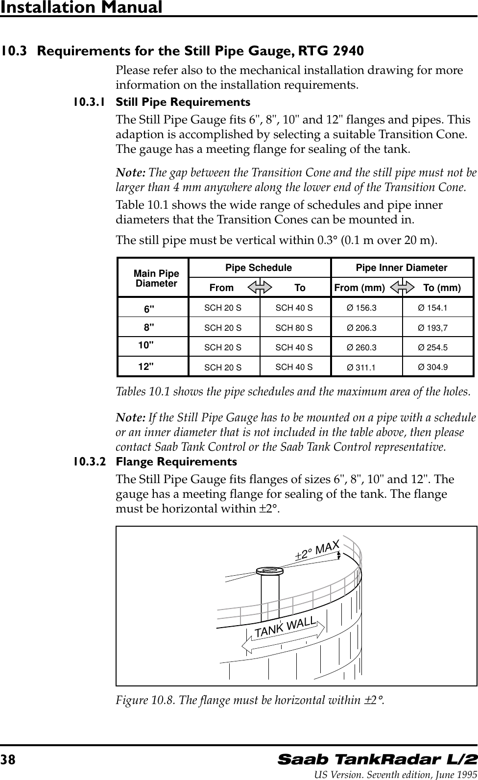
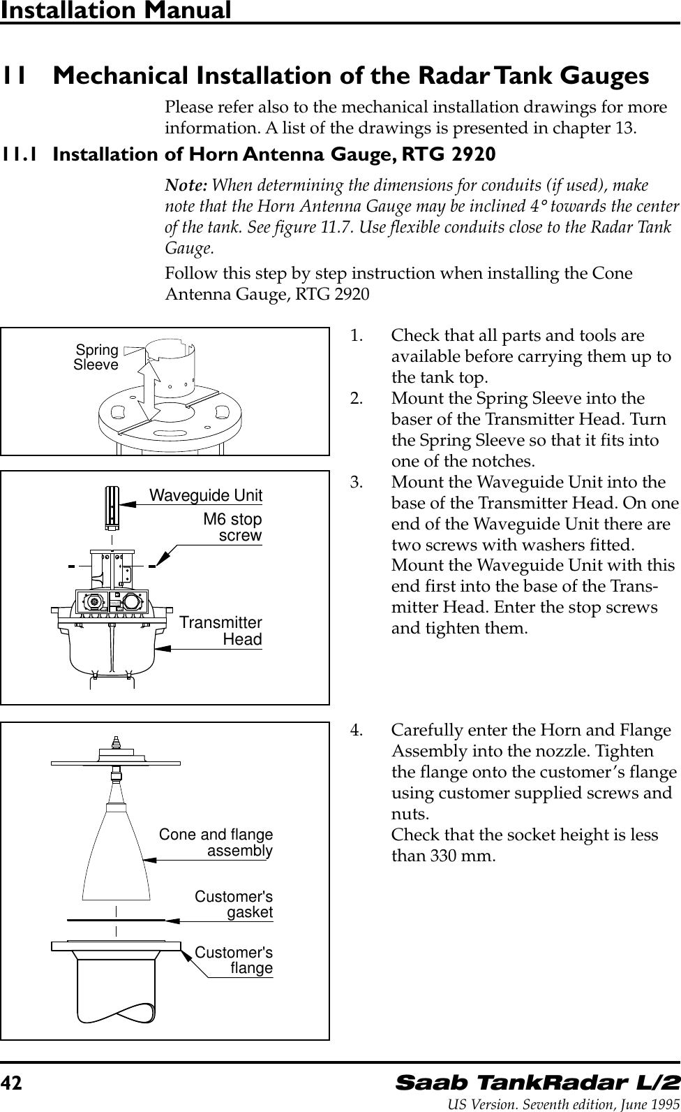
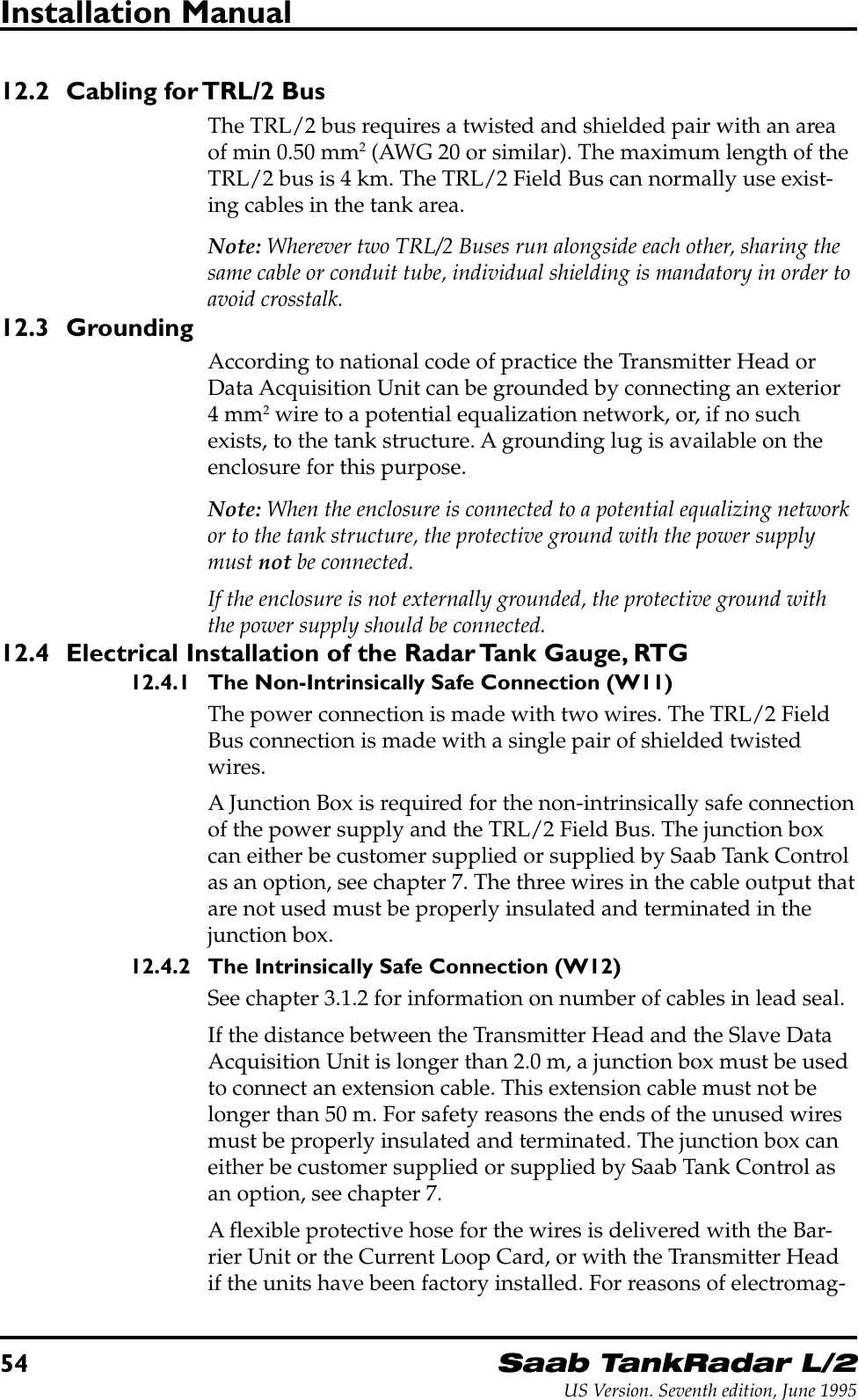
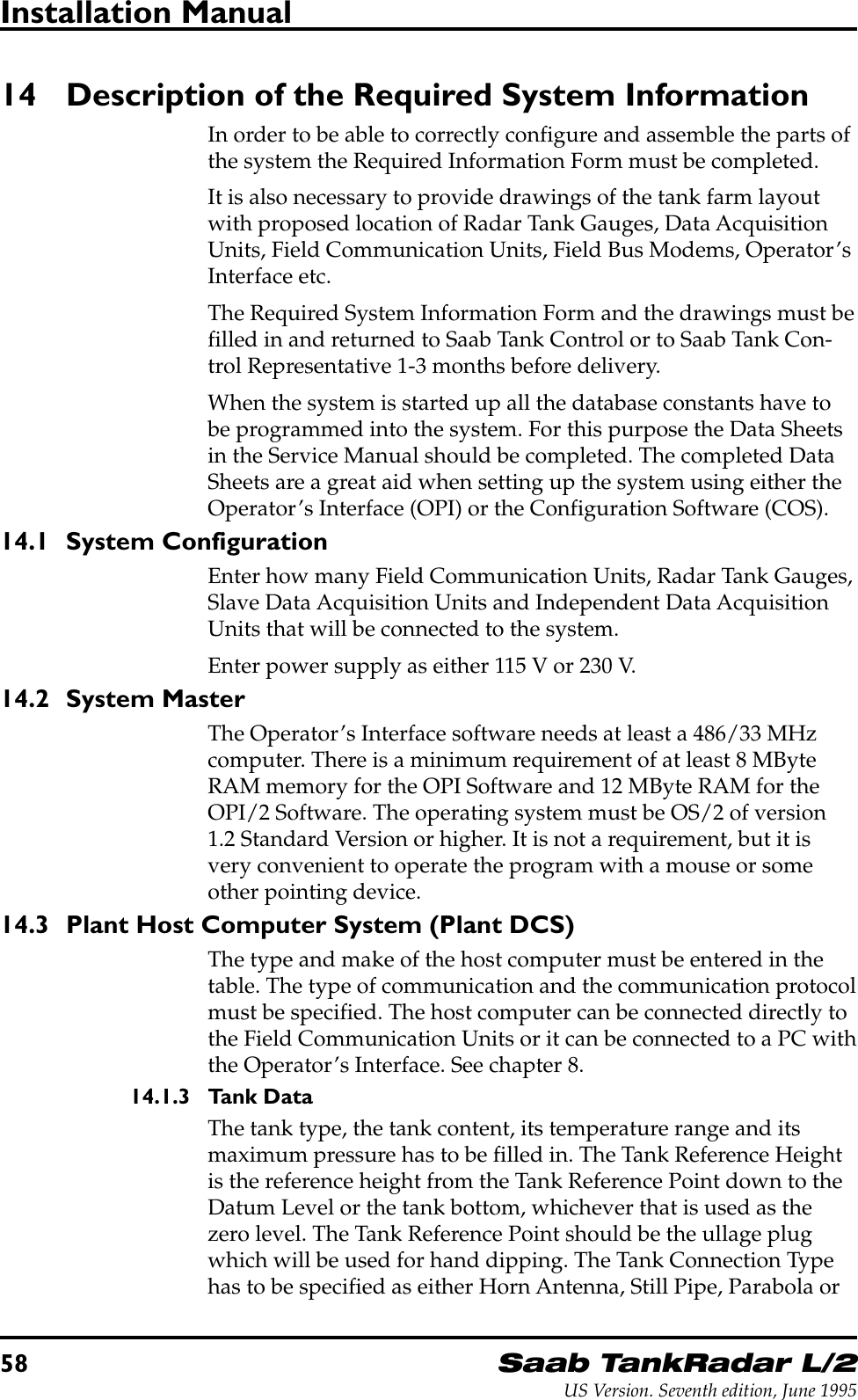
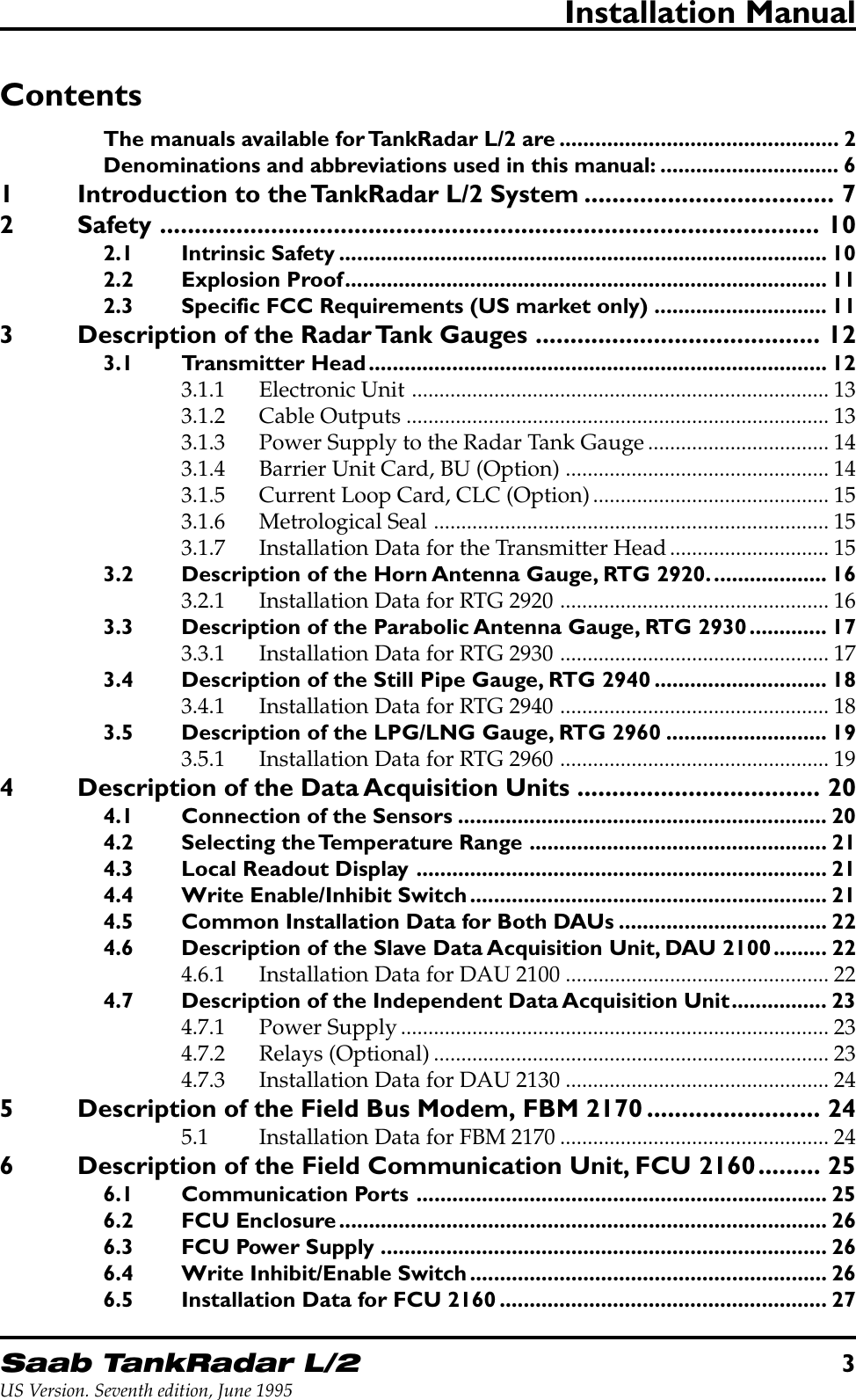
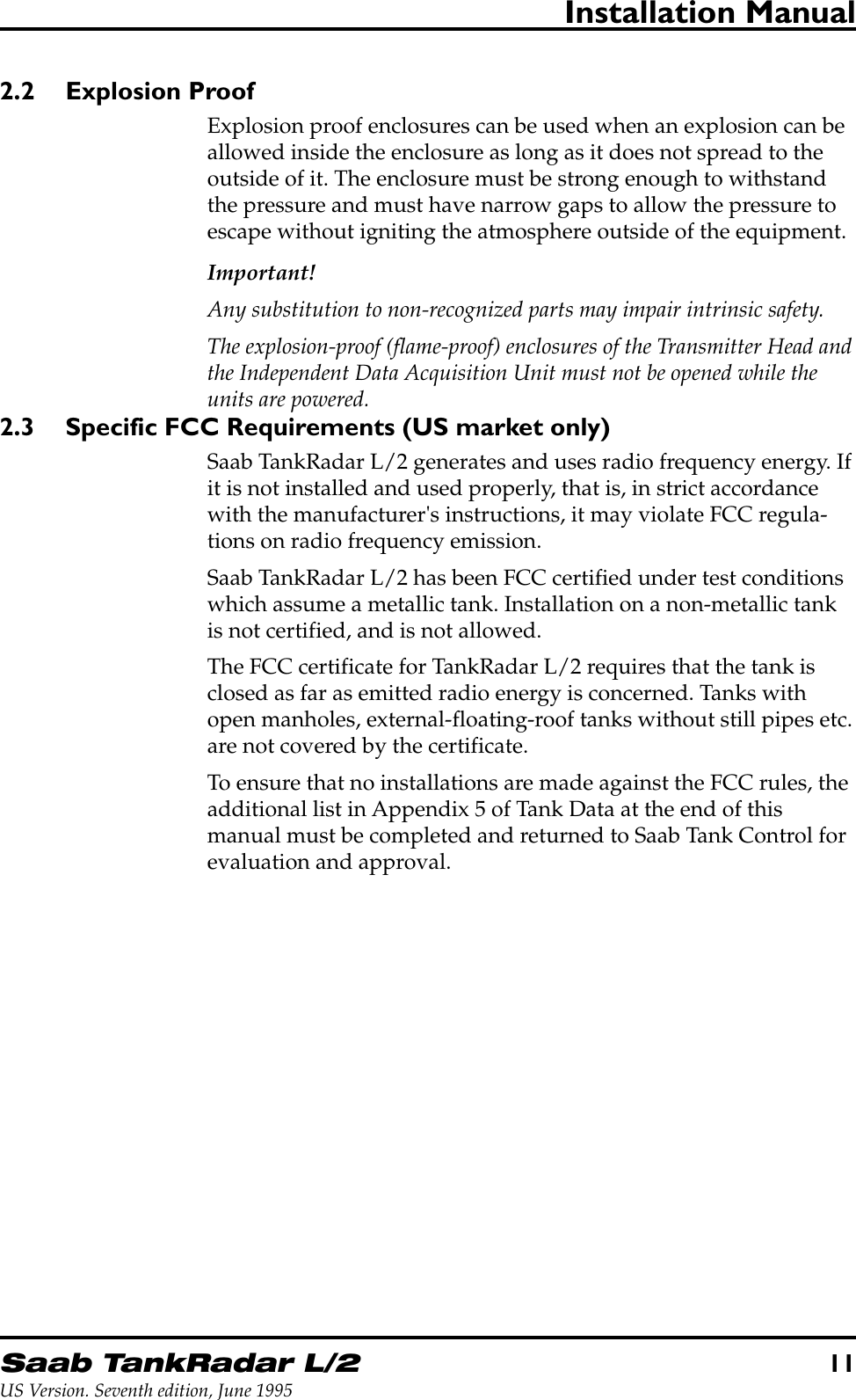
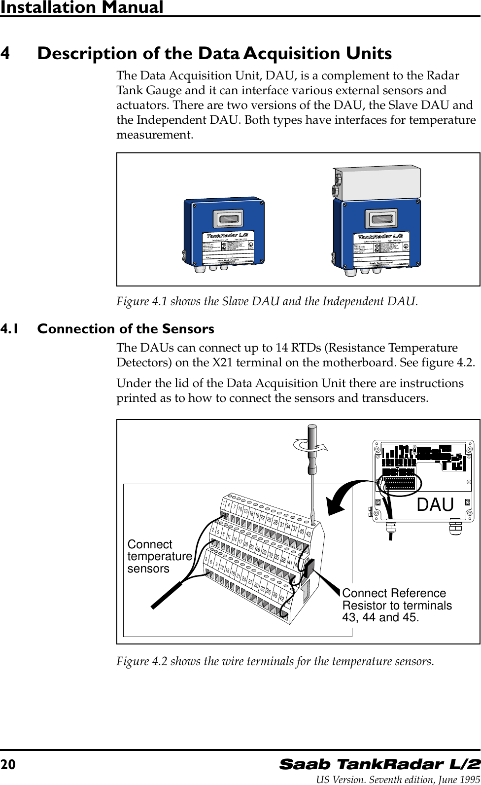
![Saab TankRadar L/215US Version. Seventh edition, June 1995Installation Manual3.1.5 Current Loop Card, CLC (Option)The optional Current Loop Card provides intrinsically safe 4-20mA inputs and outputs. The inputs can be used for example forpressure sensors, while the outputs can be used for pointer instru-ments or for output of a measured value as an analog signal.If a Slave DAU is also connected, two 4-20 mA inputs and two 4-20 mA outputs are available. If a Slave DAU is not connected, oneadditional 4-20 mA input is available, although this transducermust have its own intrinsically safe power supply.When the optional Current Loop Card is used, the JB 12 JunctionBox from Saab Tank Control is recommended since the cables areseparated inside the box according to the requirements for intrin-sic safety. See chapter 7.2.W11W12FORINTRINSICALLYSAFE CIRCUITSONLY"i"~2 m cablewithprotectivehoseTransmitter Head withCurrent Loop CardSignalPower230/115 V~2 m cablewithprotectivehoseJB 12 JB 16AnaloginputsAnalogoutputsFigure 3.5 shows a Transmitter Head with a Current Loop Card.3.1.6 Metrological SealThe Metrological Seal consists of a rod that can activate a write-enable switch from the outside of the Transmitter Head. This rodcan be sealed in the write-inhibit position to prevent unauthorizedchanges in the database.If there is no Metrological Seal mounted, then the TransmitterHead is always in write-enable mode.3.1.7 Installation Data for the Transmitter HeadAmbient operating temperature: -40°C to +65°C(-40°F to +149°F)Explosion protection Class 1, Div I, Groups C and D(UL1203, UL913 USA) andEEx d[ia] IIB T4 (EN50014,EN50018 and EN50020 Europe)Power Supply 115 or 230 VAC, +10% to -15%,50-60 Hz, max. 80 WField bus TRL/2 Bus (FSK, half duplex,two wires, galvanically iso-lated, 4800 Baud)](https://usermanual.wiki/Rosemount-Tank-Radar/REX/User-Guide-28351-Page-15.png)
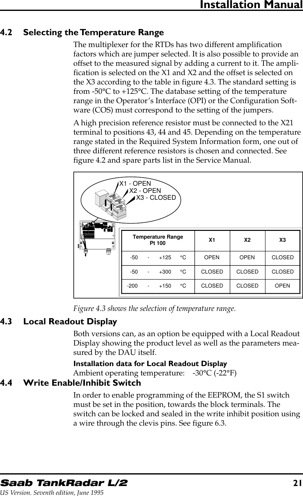
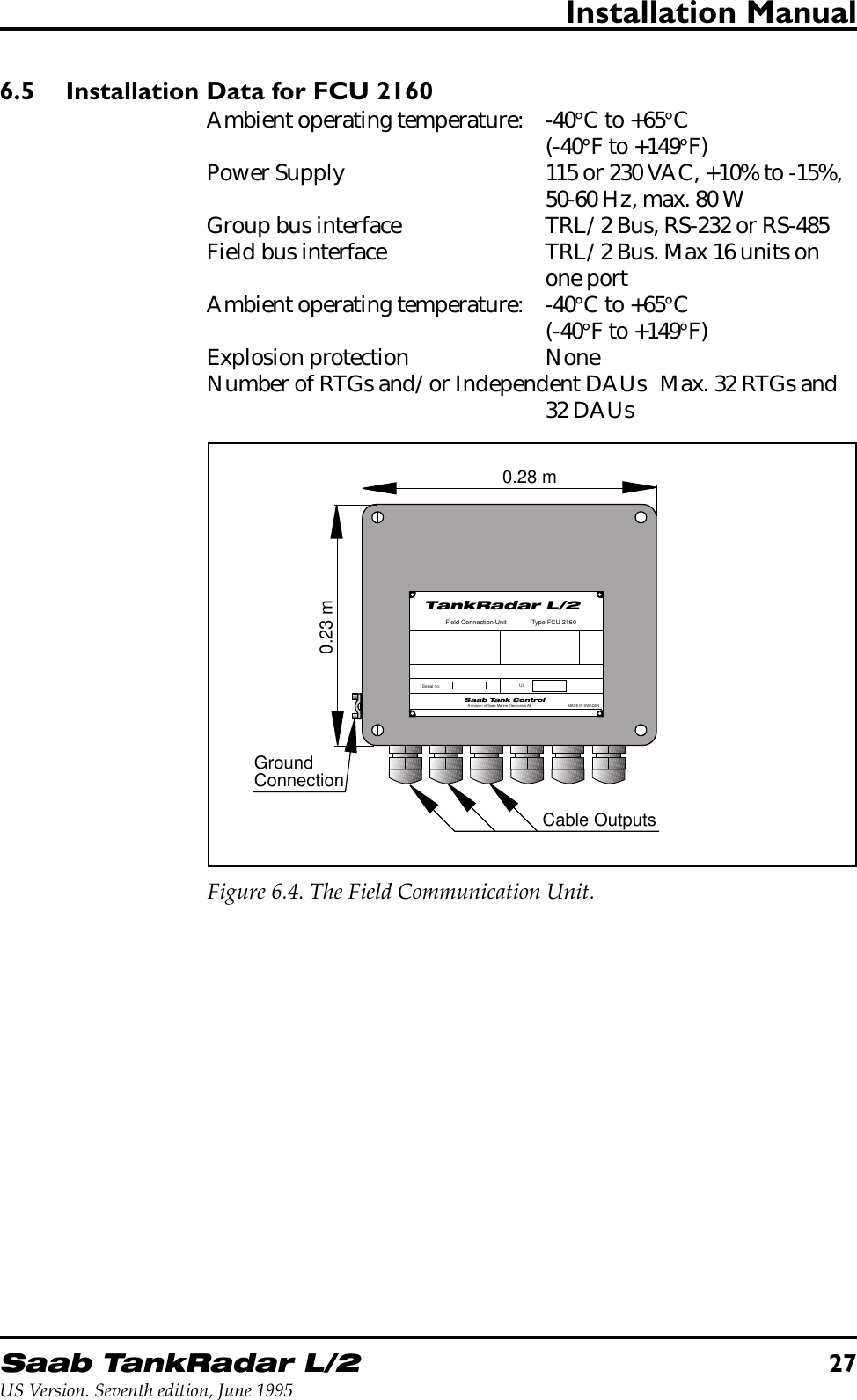
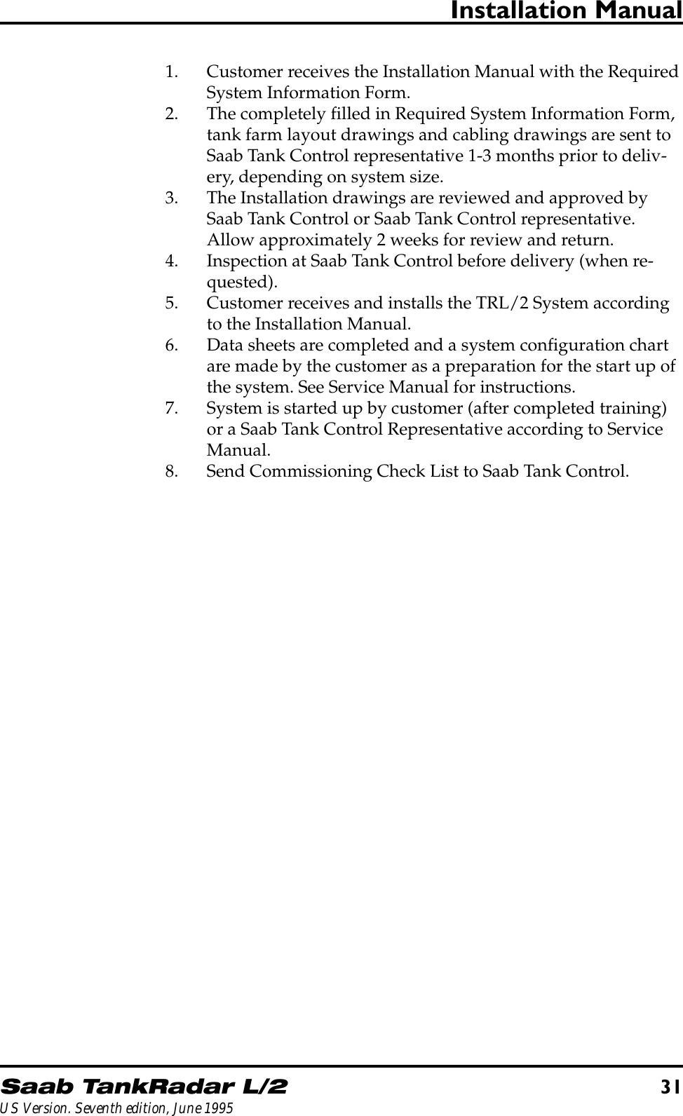
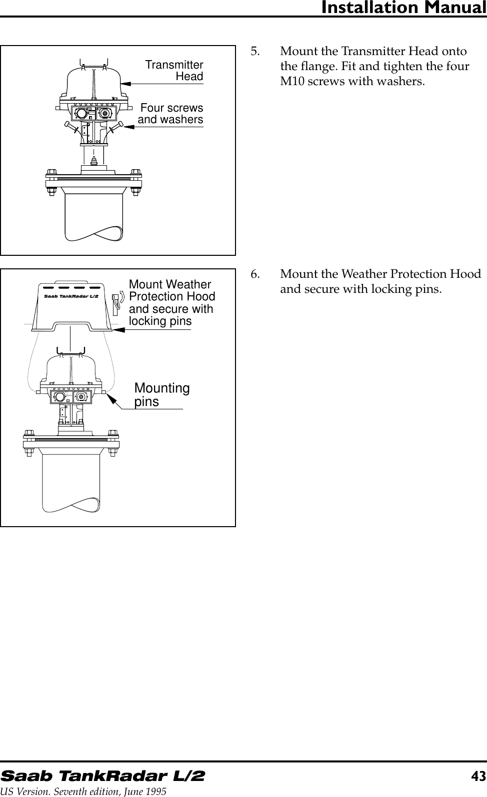
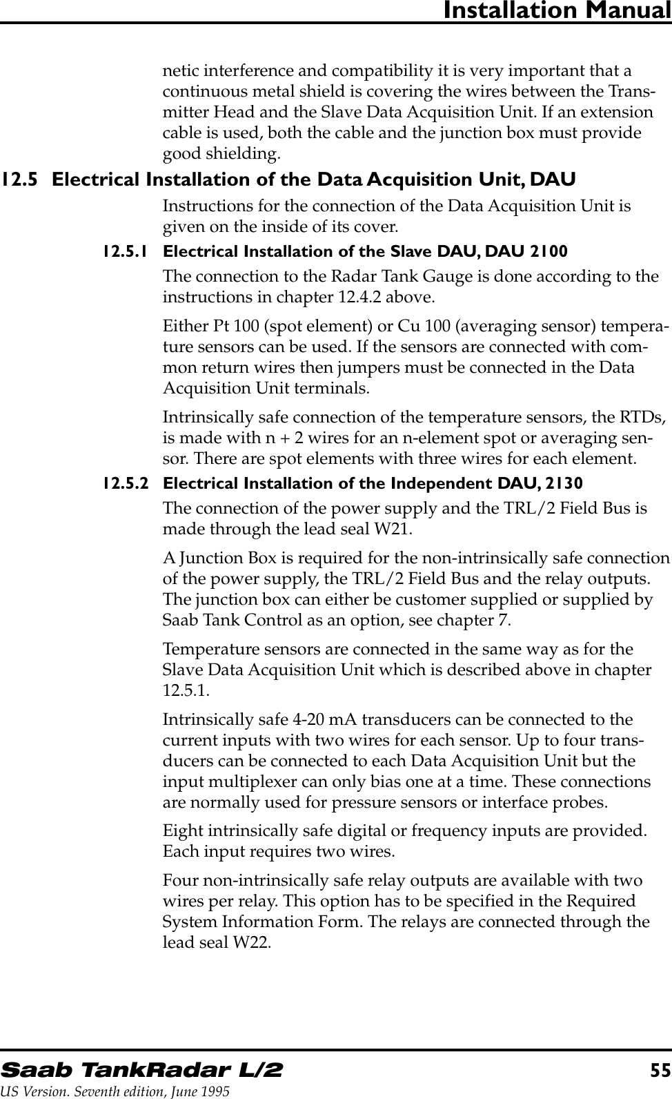
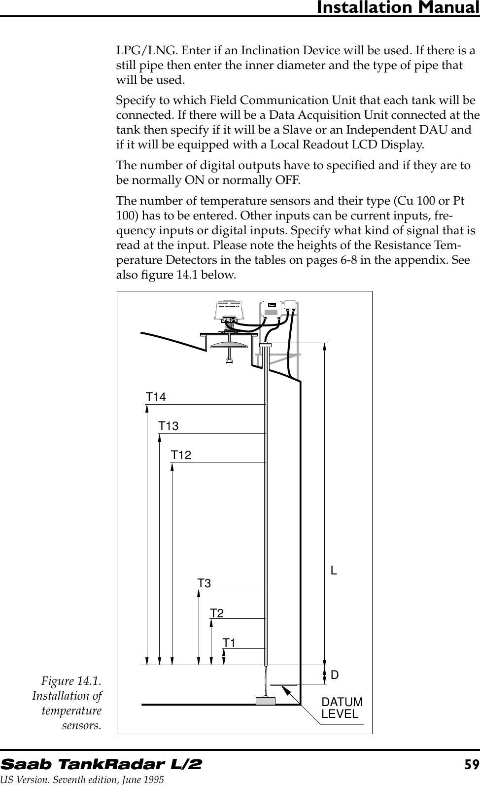
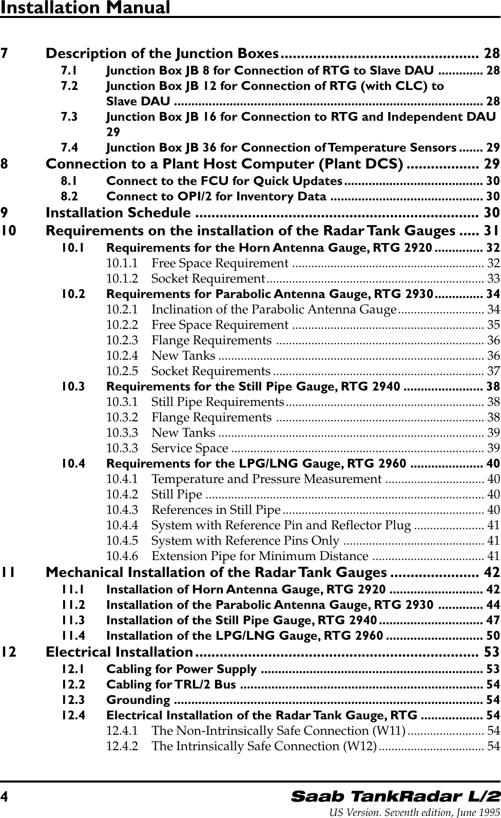
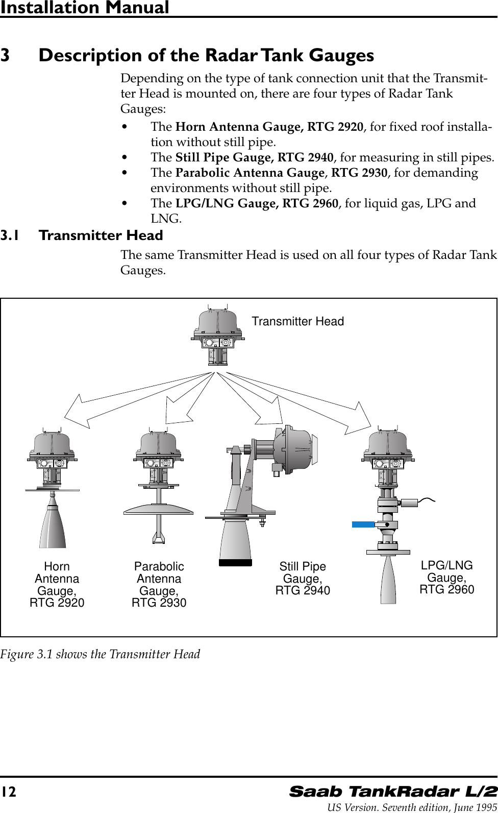
![24Saab TankRadar L/2US Version. Seventh edition, June 1995Installation Manual4.7.3 Installation Data for DAU 2130Explosion protection Class 1, Div I, Groups C and D(UL1203, UL913 USA) andEEx d[ia] IIB T4 (EN50014,EN50018 and EN50020 Europe)Power Supply 115 or 230 VAC, +10% to -15%,50-60 Hz, max. 10 WField bus TRL/2 Bus (FSK, half duplex,two wires, galvanically iso-lated, 4800 Baud)Current inputs 4-20 mA. Intrinsically safe.Number of current inputs Max. 4, multiplexed, only one ispowered at a timeNumber of status and frequencyinputs Max. 8. Intrinsically safe.Number of relay outputs Max. 4Relay contact rating 250 VAC / 5A (resistive load)5 Description of the Field Bus Modem, FBM 2170The Field Bus Modem, FBM, is a converter between RS-232C andthe TRL/2 Bus. It is used for connecting a PC with OPI (or COS) tothe TRL/2 Bus.Note: No explosion protection is provided, so the Field Bus Modem mustbe installed in a non-hazardous area.5.1 Installation Data for FBM 2170Power supply From AC/DC converter sup-plied by Saab Tank Control. 6-15 V, 10 mA).Cable to PC Supplied by Saab Tank ControlExplosion protection NoneSaab MarineElectronicsX2 X1Conn.to PCConn. to TRL/2Field Bus0.065 m0.115 mFigure 5.1 shows the Field Bus Modem.](https://usermanual.wiki/Rosemount-Tank-Radar/REX/User-Guide-28351-Page-24.png)