Rosemount 3308A Wireless Guided Wave Radar Level Transmitter User Manual Book 3300 DA
Rosemount Inc Wireless Guided Wave Radar Level Transmitter Book 3300 DA
UserManual.wiki
>
Rosemount
>
3308A User Manual
User Manual
Navigation menu
Upload a User Manual
Namespaces
Wiki Guide
HTML
PDF
Info
Views
User Manual
Discussion / Help
Navigation


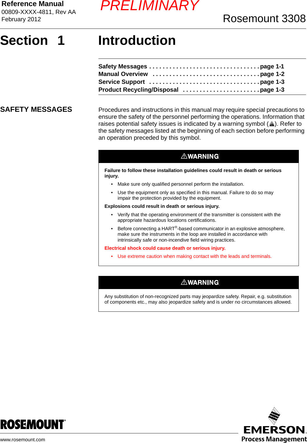

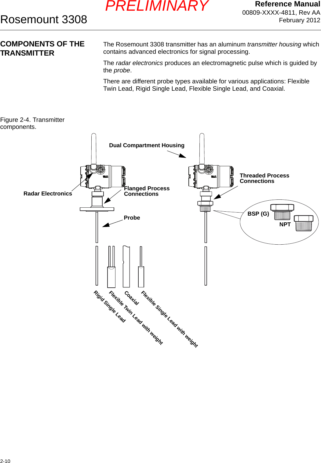

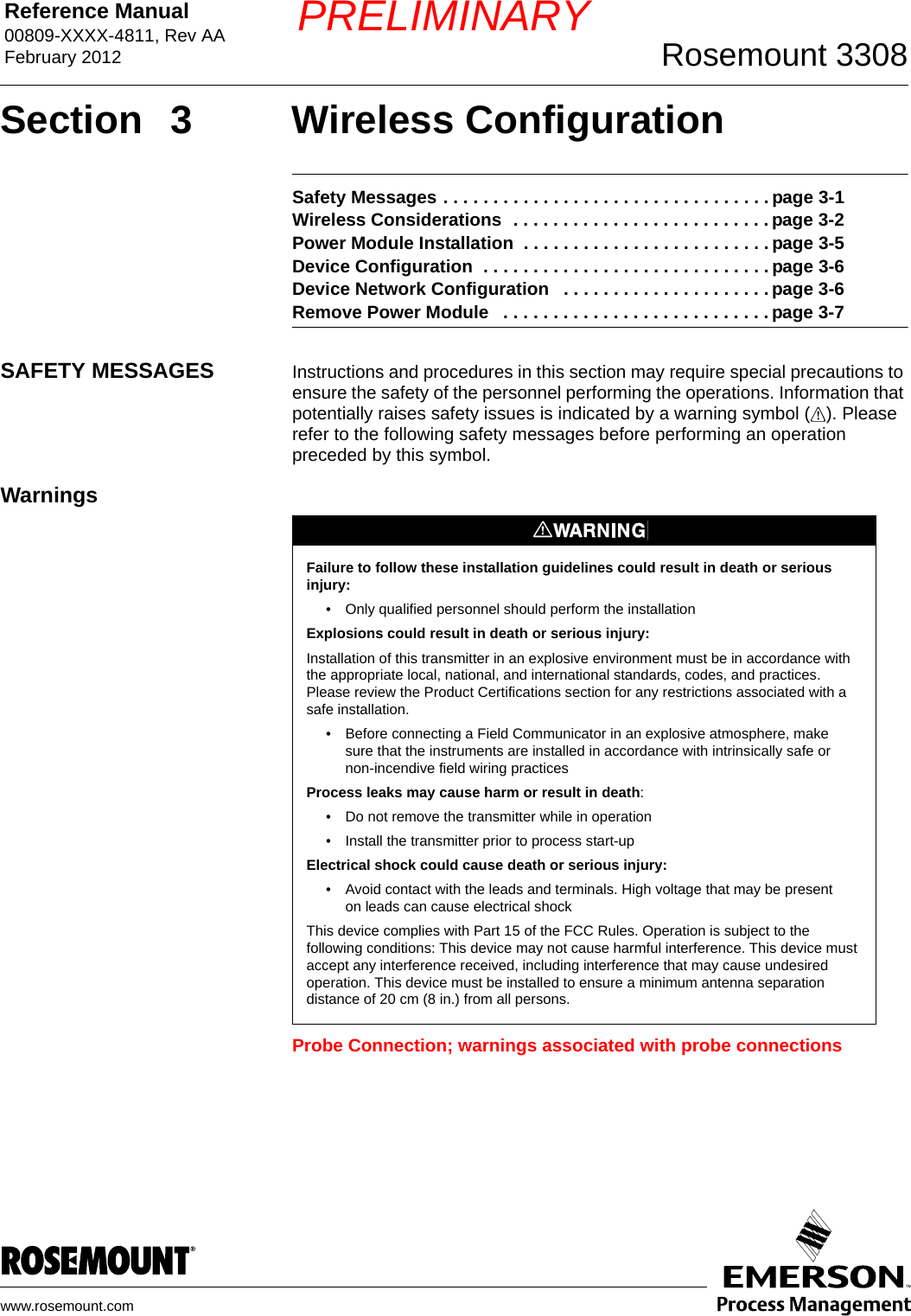
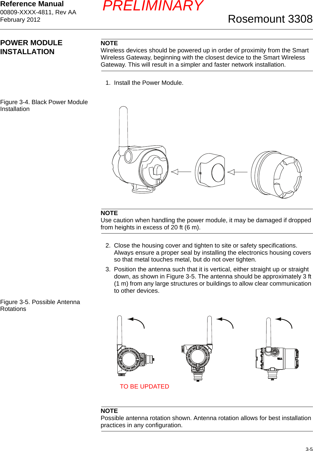

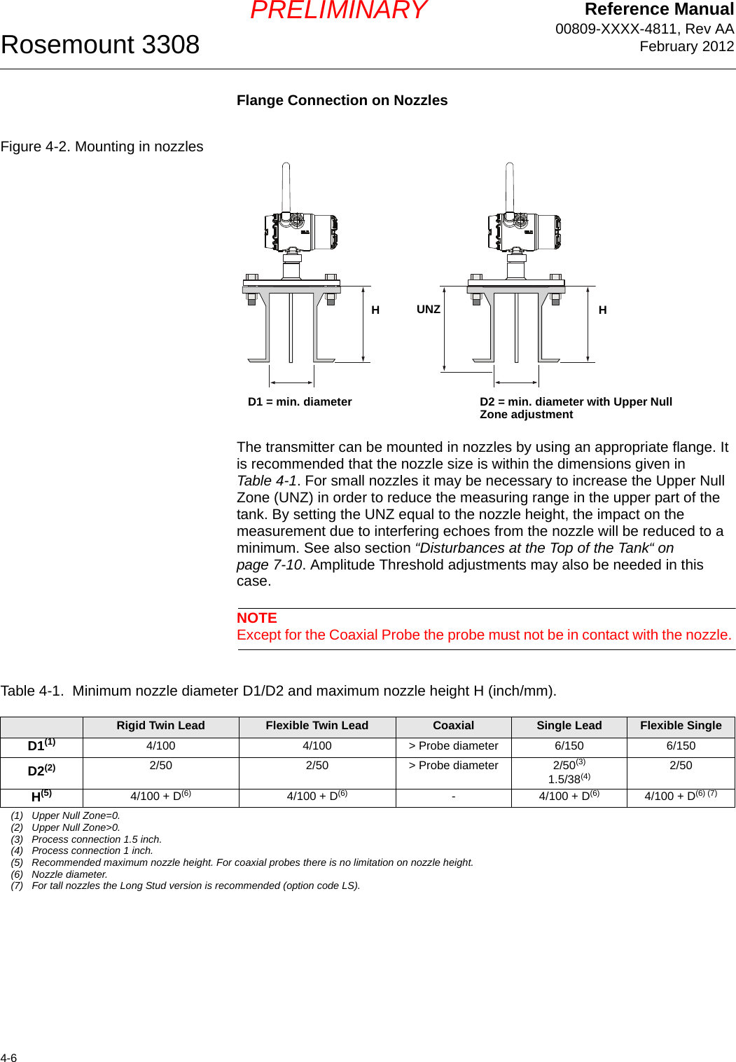
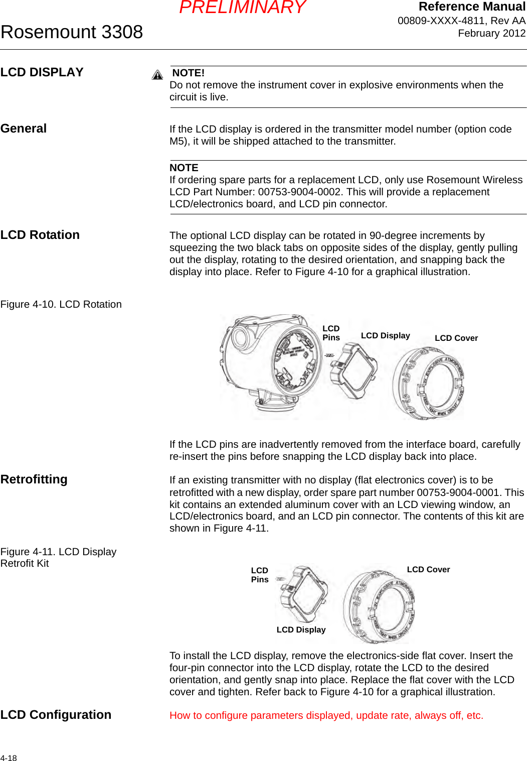

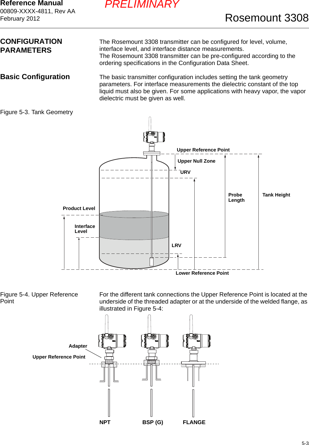
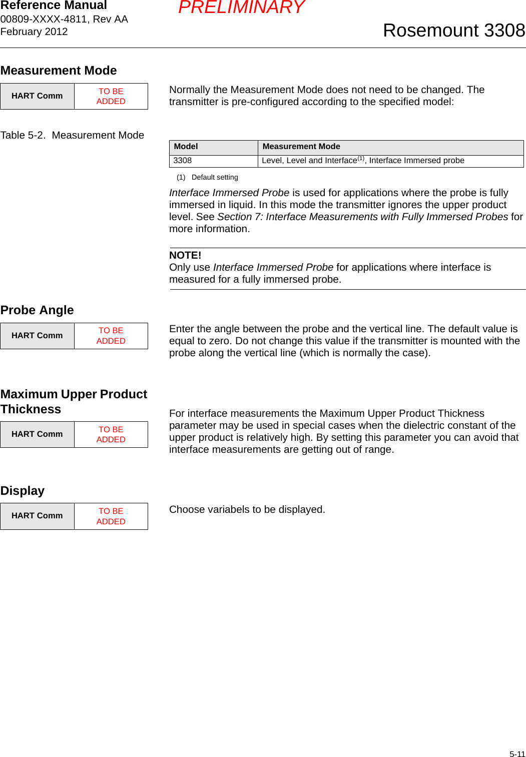
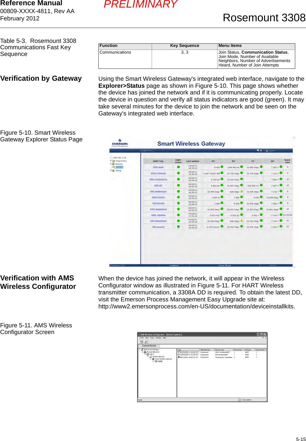
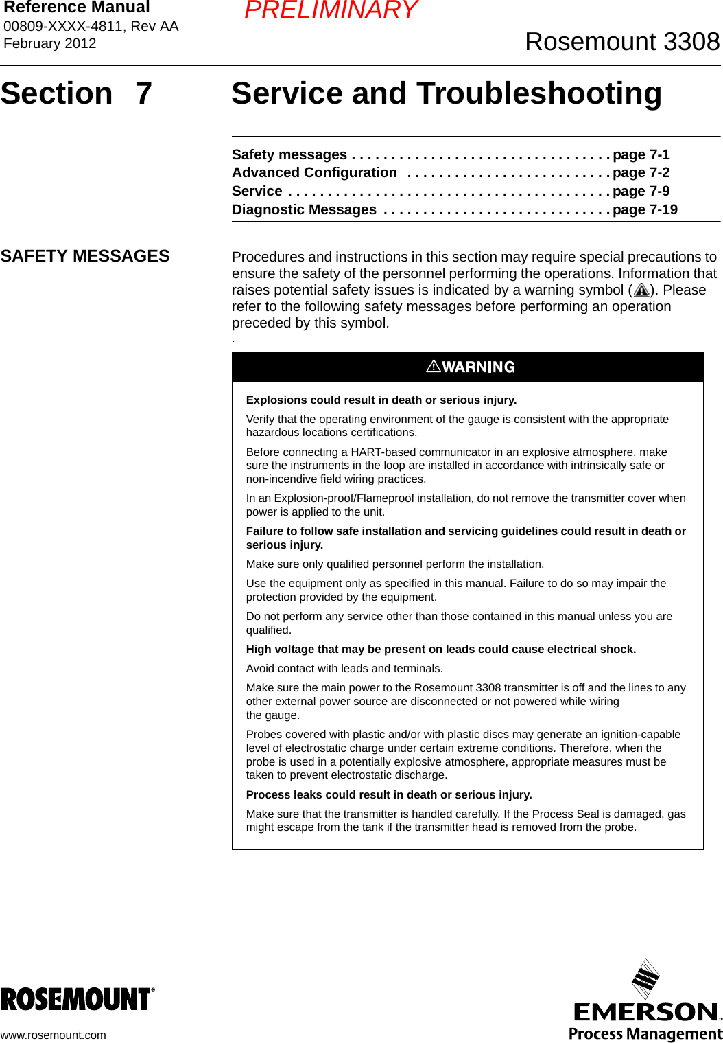
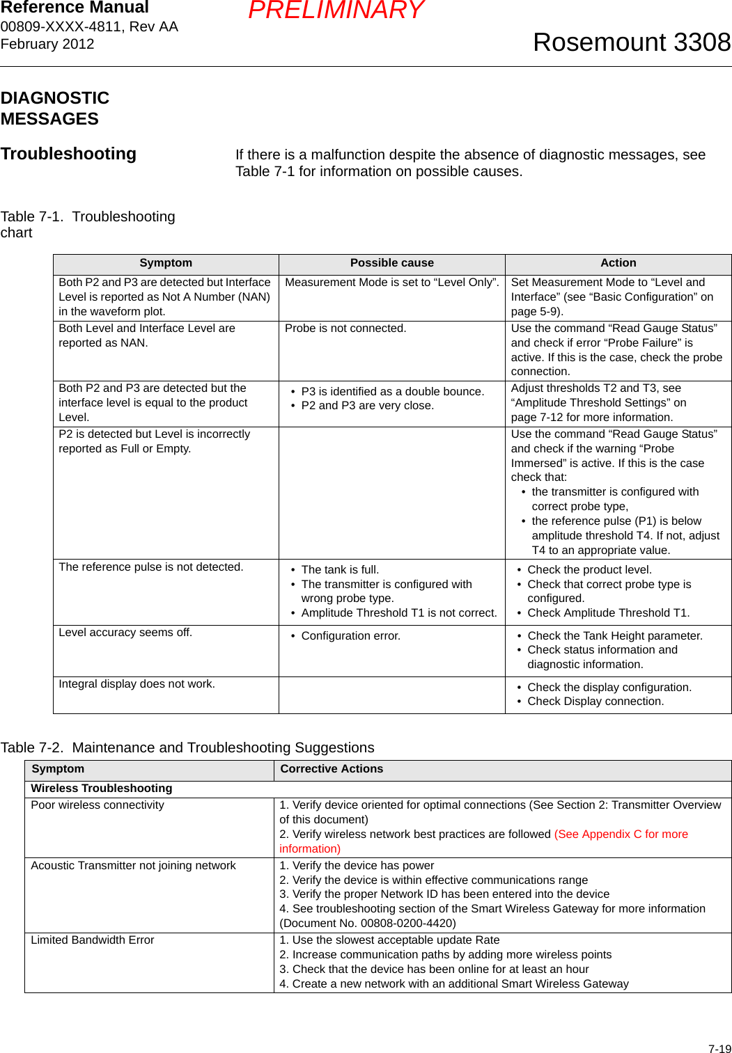
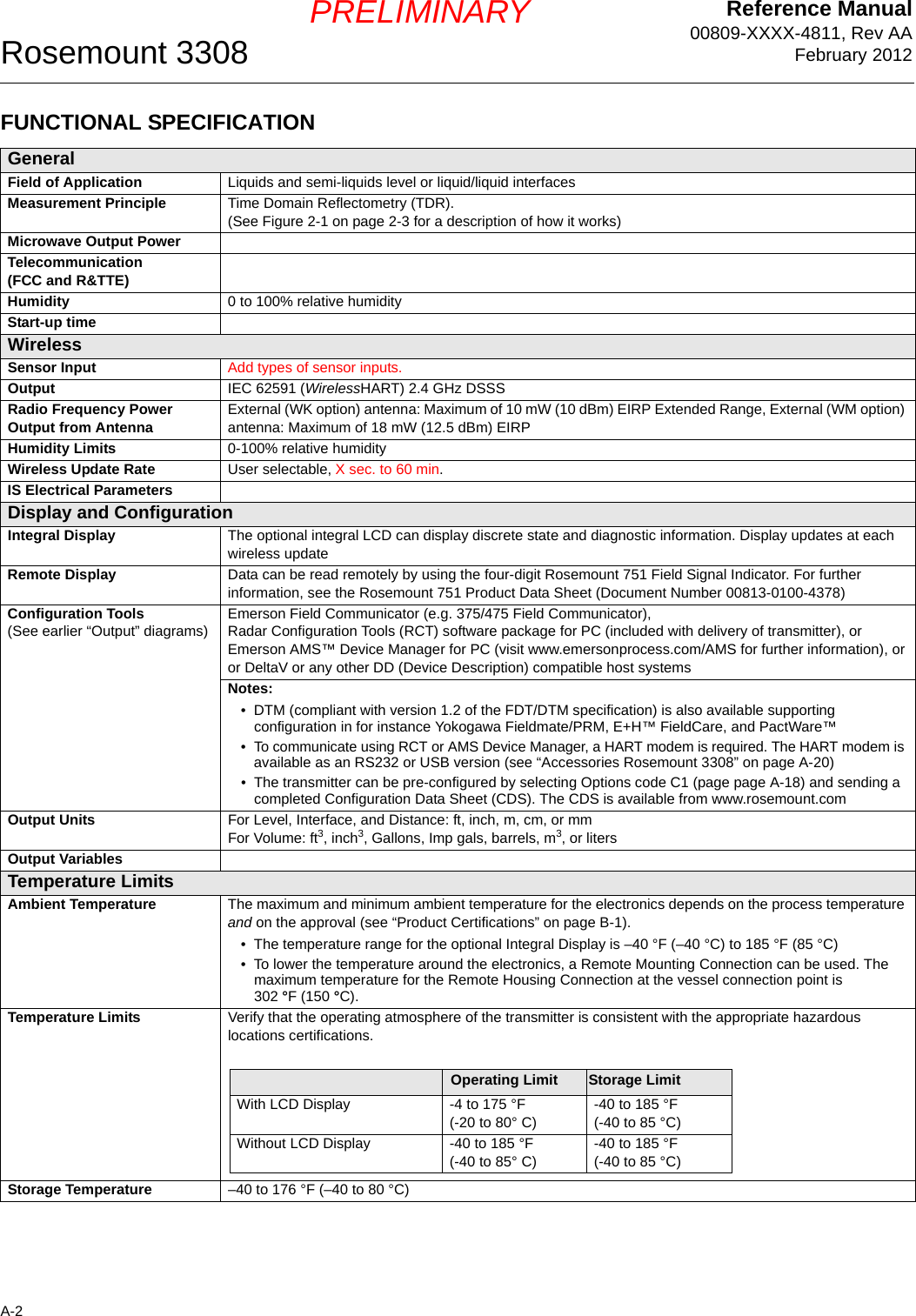
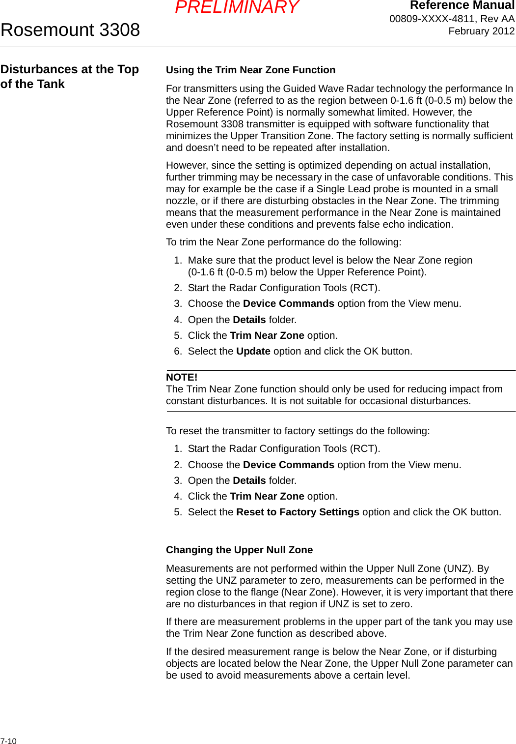
![Reference Manual00809-XXXX-4811, Rev AAFebruary 2012Rosemount 33087-2PRELIMINARYADVANCED CONFIGURATION This section covers non-standard configuration.User defined Upper Reference Point If you want to specify your own Upper Reference Point you can do this by setting the Calibration Offset parameter. Figure 7-1. Tank GeometryTo set the desired upper reference point do the following:1. Adjust the Tank Height to the distance from the tank bottom to the desired Upper Reference Point.2. Add the distance between the Upper Reference Point and the Transmitter Reference Point to the Calibration Offset value that is stored in the transmitter database. With the HART Communicator the Calibration Offset is available as HART Fast Key sequence [1, 4, 5, 5].In Radar Configuration Tool (RCT) the Calibration Offset is available under the Advanced section in the RCT Project Bar:Device Commands>Basic>Set Calibration Offset.Tank HeightProduct LevelUpper Reference Point Transmitter Reference PointCalibration Offset](https://usermanual.wiki/Rosemount/3308A/User-Guide-1654908-Page-82.png)
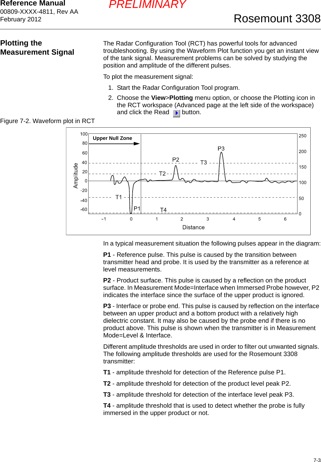
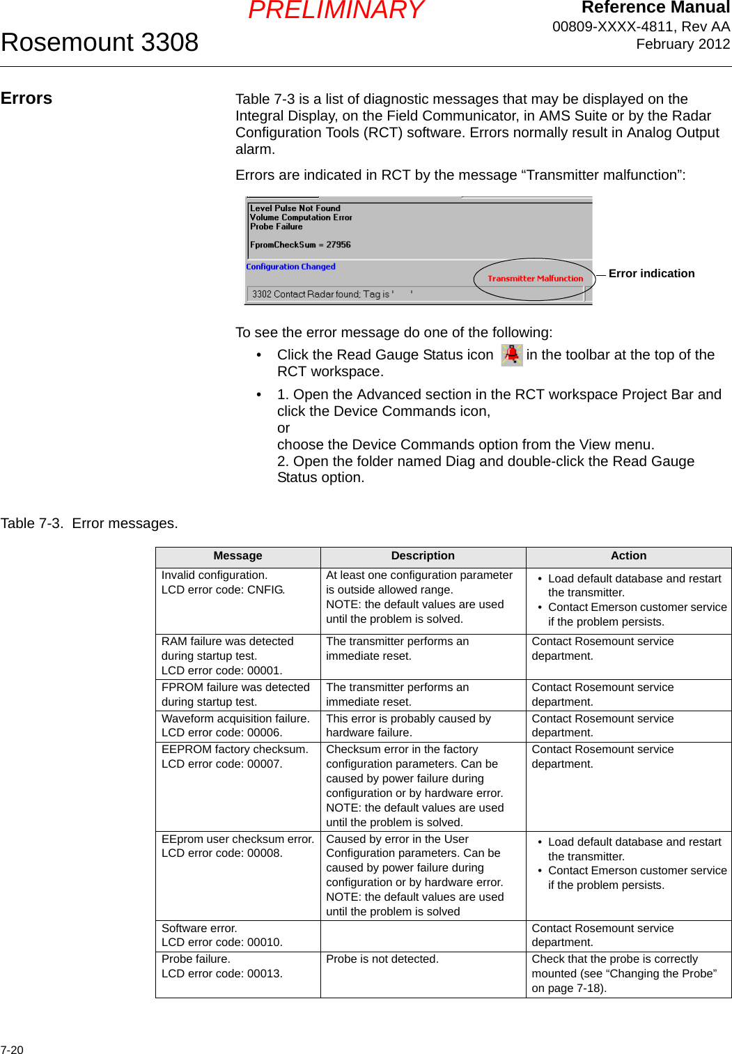
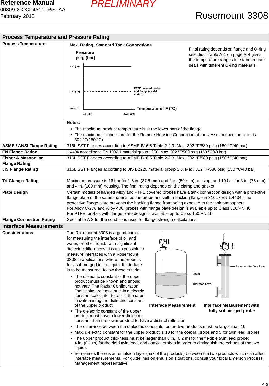
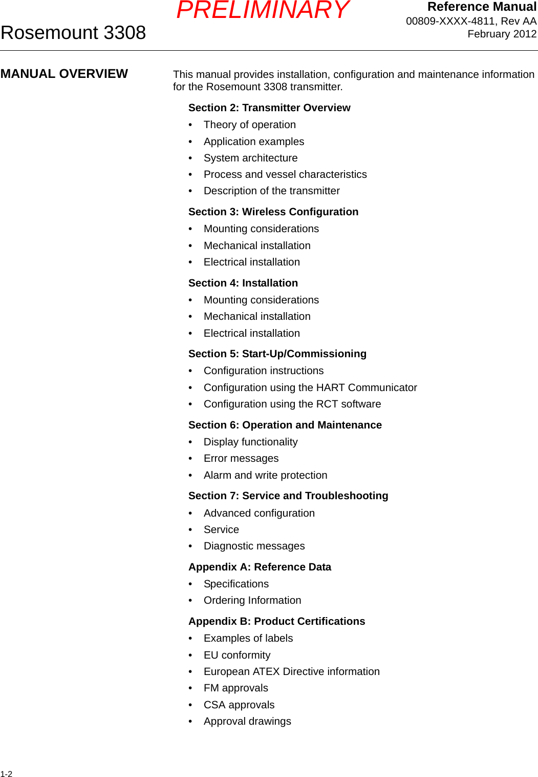
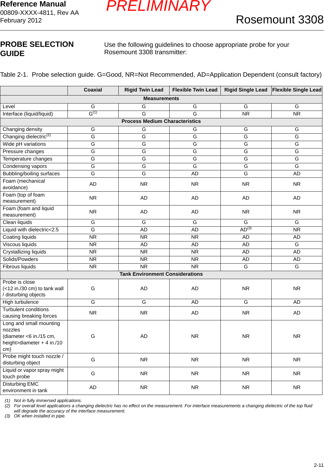
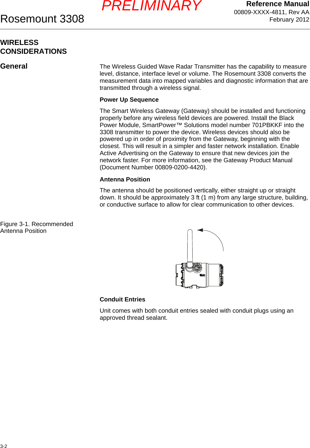
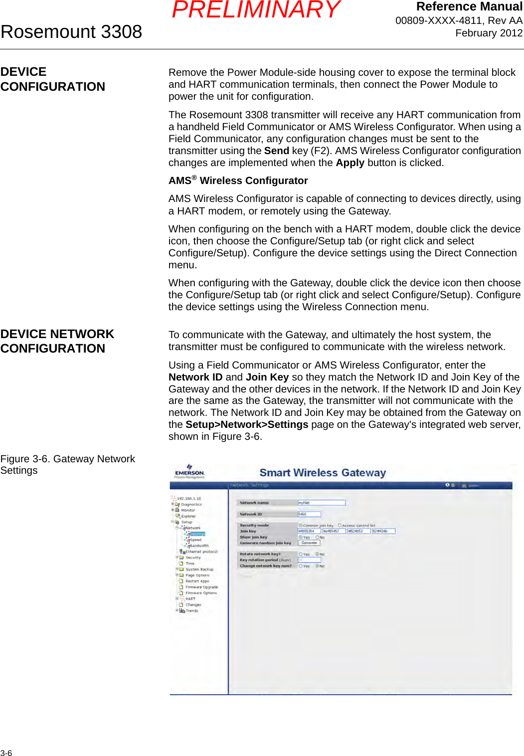
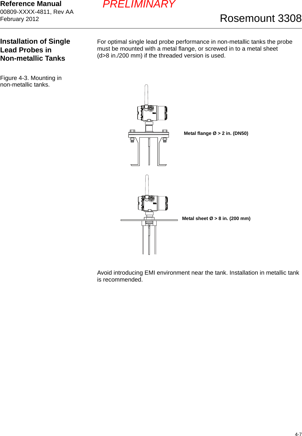
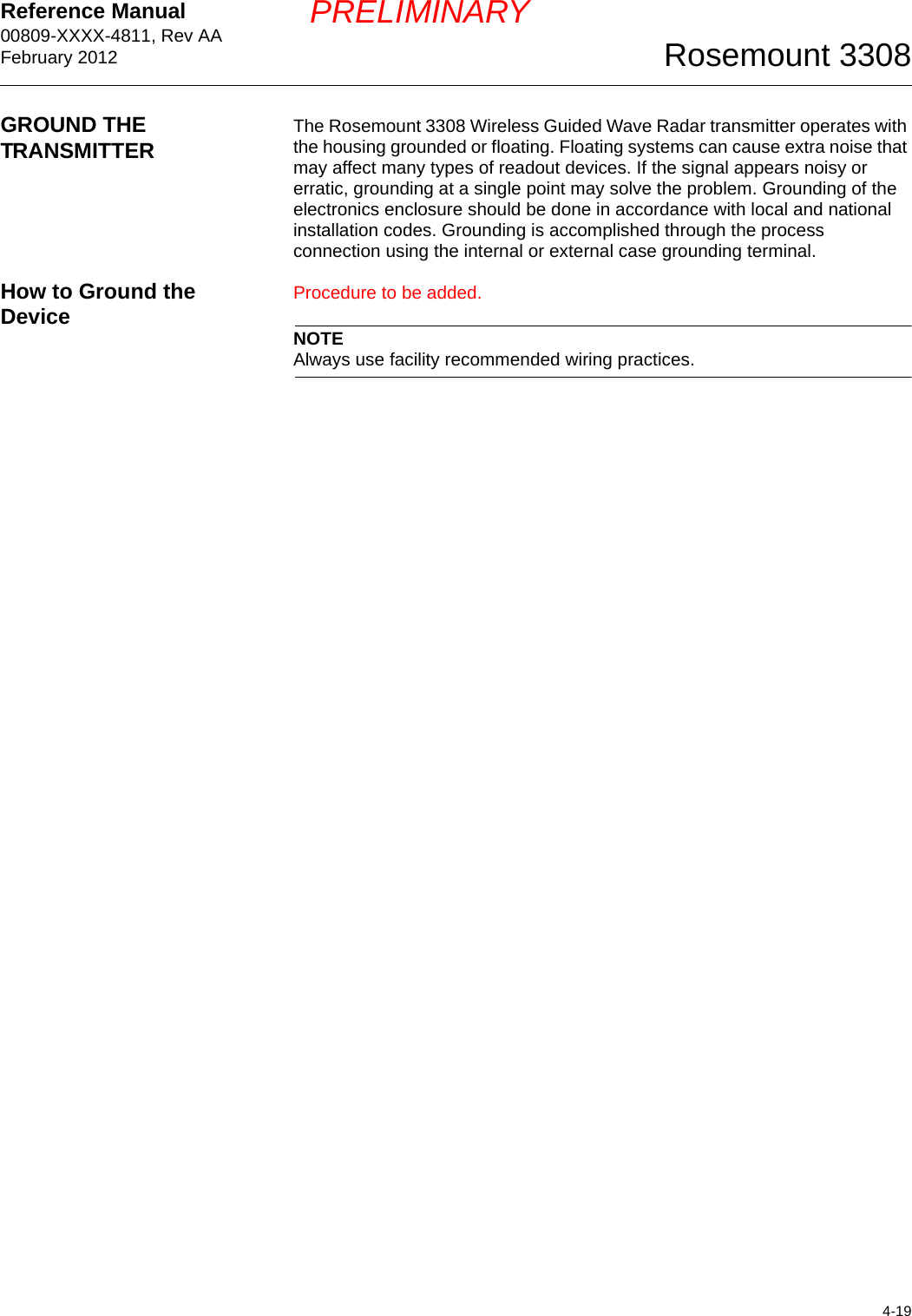
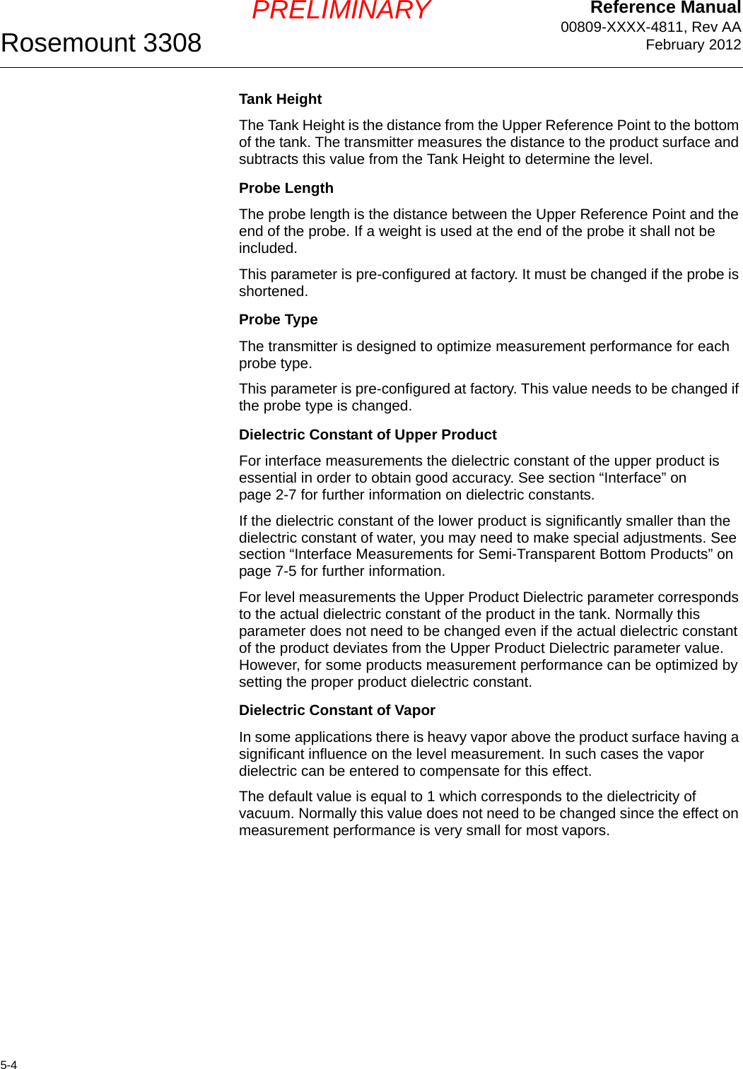
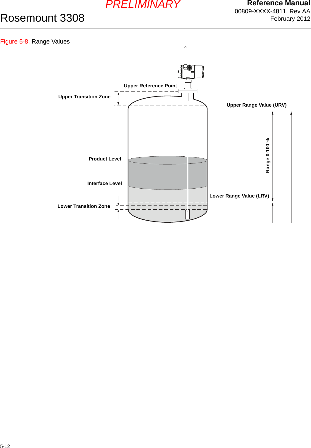
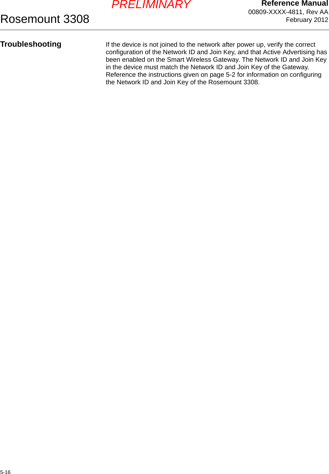
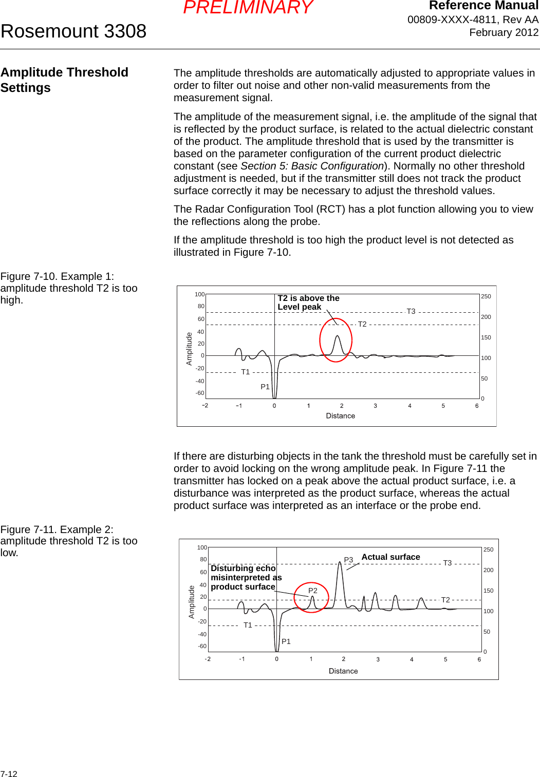
![Reference Manual 00809-XXXX-4811, Rev AAFebruary 20127-5Rosemount 3308PRELIMINARYInterface Measurements for Semi-Transparent Bottom ProductsIn interface applications where the bottom product has a low dielectric constant, or if the signal is attenuated in the upper product, the amplitude of the reflected signal is relatively low and difficult for the transmitter to detect. In such a case it may be possible to detect the reflected signal if the corresponding amplitude threshold is adjusted.The Radar Configuration Tool (RCT) lets you view a waveform plot to analyze the measurement signal. The plot shows the signal and the thresholds used for the different amplitude peaks. By adjusting amplitude threshold T3 it is possible to detect even weak interface signals. Guidelines for amplitude threshold settings:• The amplitude threshold T3 should be approximately 50 % of the interface signal amplitude.• Threshold T3 should not be less than 3.• If possible, T3 should be higher than T2.You can use the RCT software or a Field Communicator to change the amplitude thresholds. For the Field Communicator use the HART command [1, 4, 5, 3]. See also “Amplitude Threshold Settings” on page 7-12.RCT lets you view a plot of the measurement signal along with the current thresholds:1. From the View menu choose the Plotting option, or double-click the Plotting icon in the Advanced section of the RCT Project Bar. 2. Click the Read button .3. To adjust the Amplitude Thresholds open the Advanced section in the RCT Project Bar and choose Device Commands>Details>Set Nominal Thresholds.Figure 7-4. Waveform plot indicating that the amplitude threshold for the interface peak is too high.The amplitude threshold is above the measurement signal peak](https://usermanual.wiki/Rosemount/3308A/User-Guide-1654908-Page-85.png)
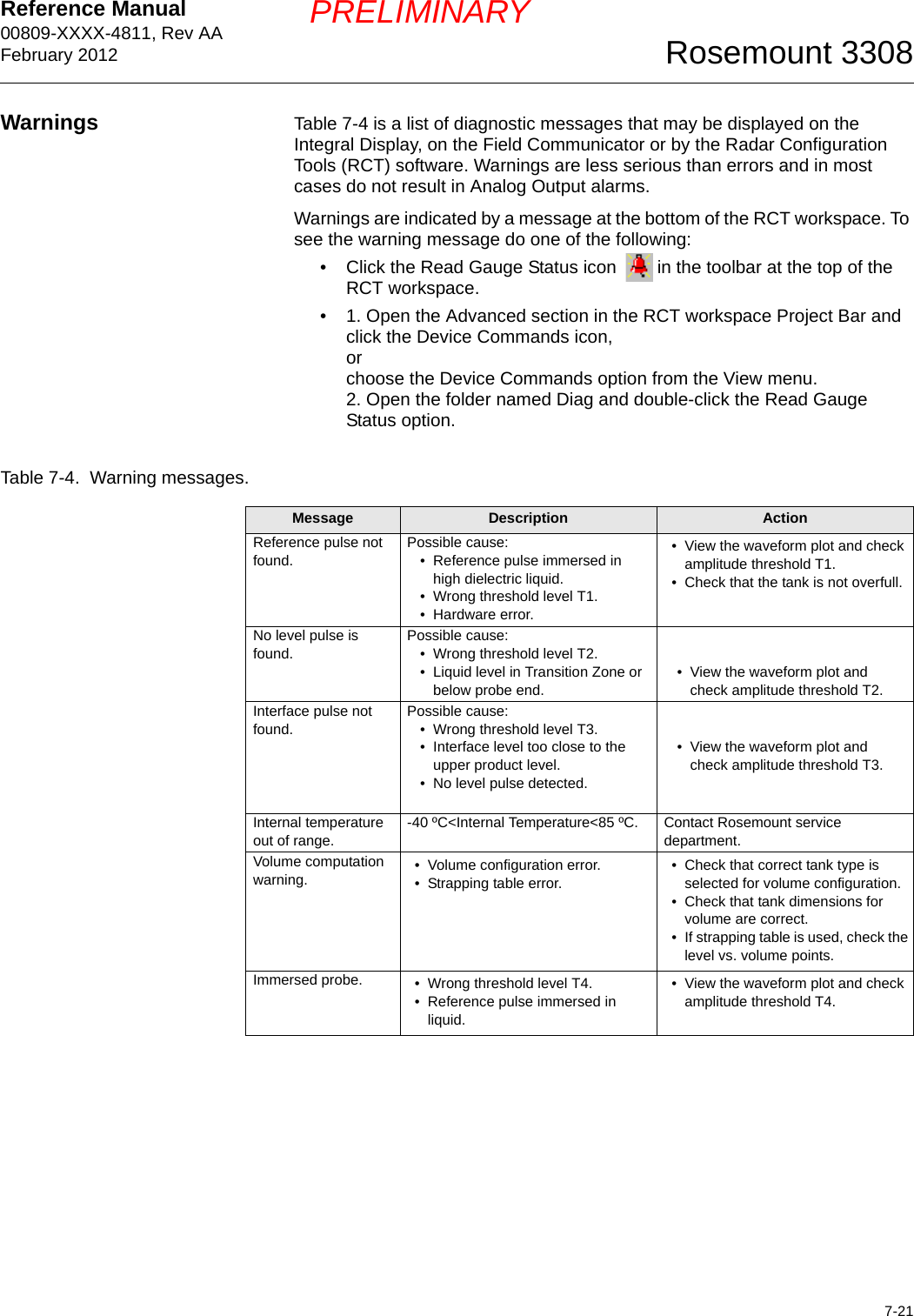
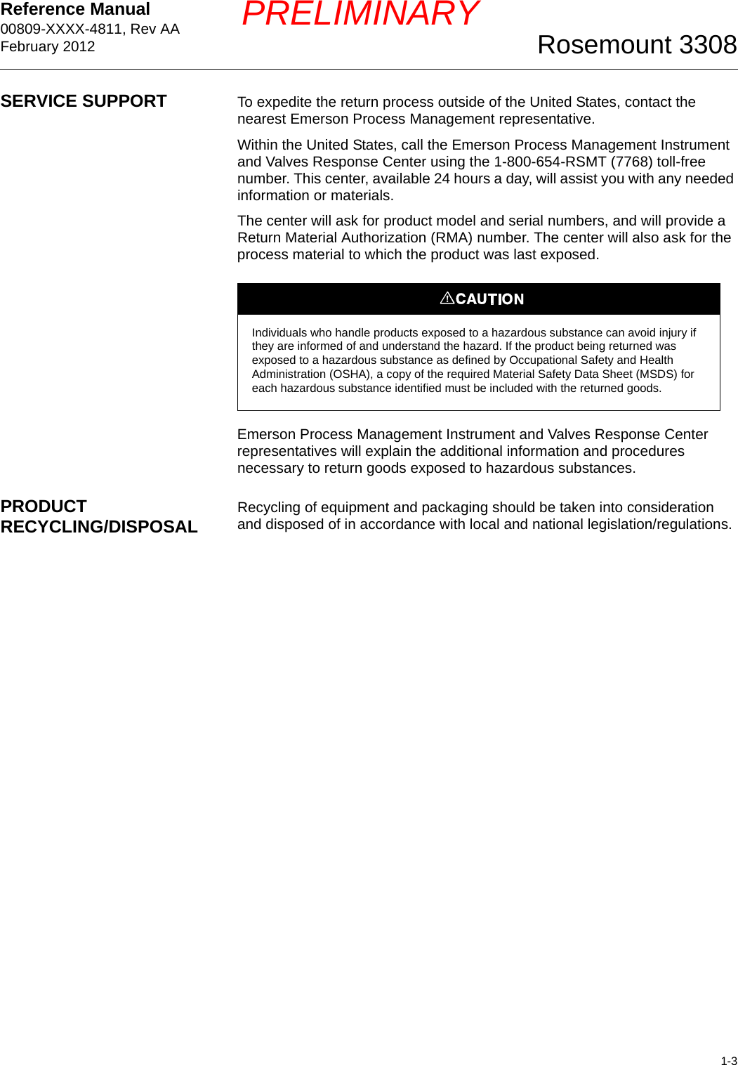
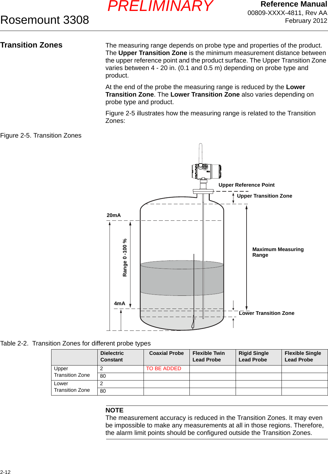
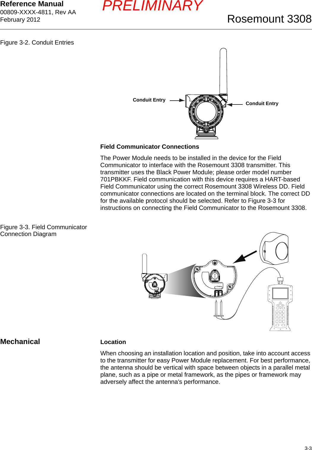
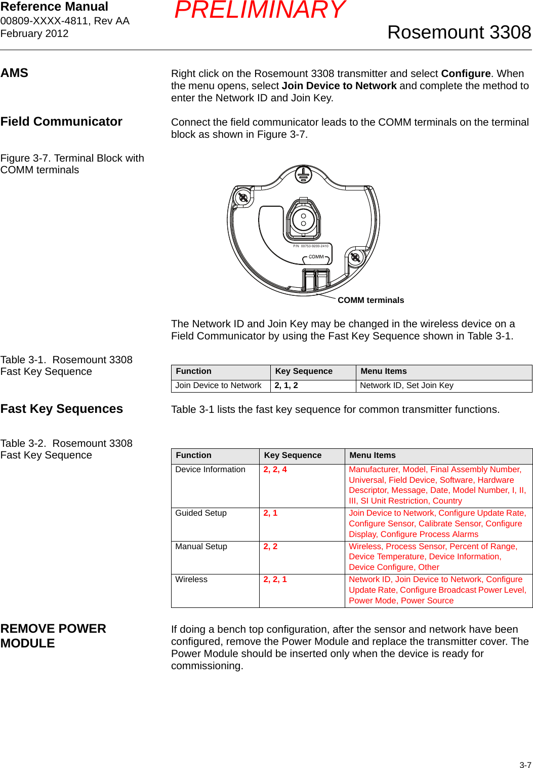
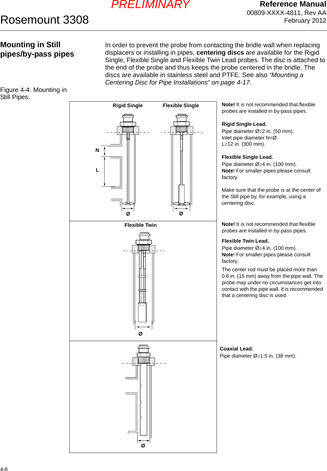
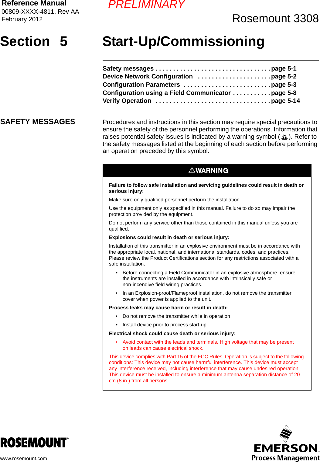
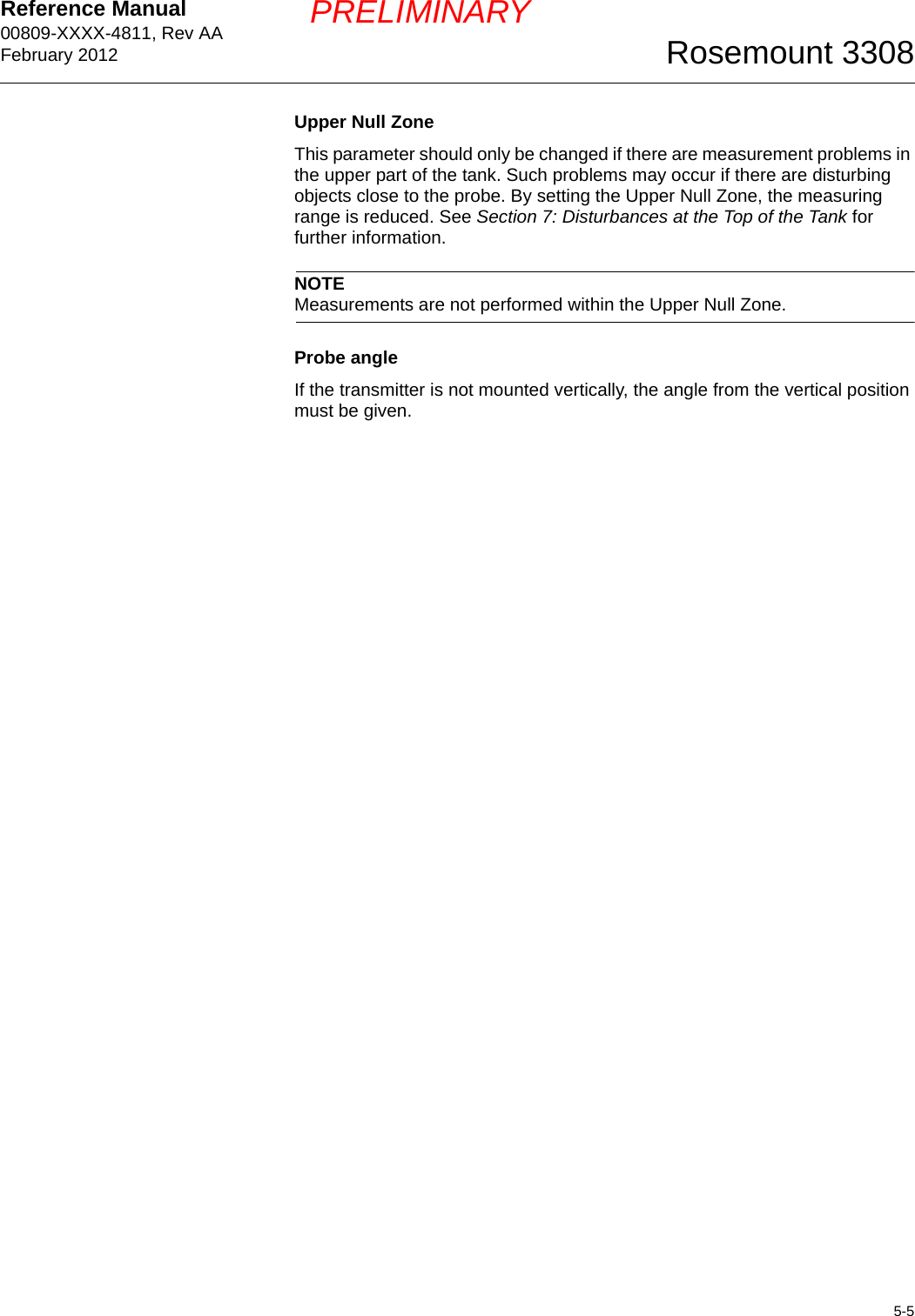
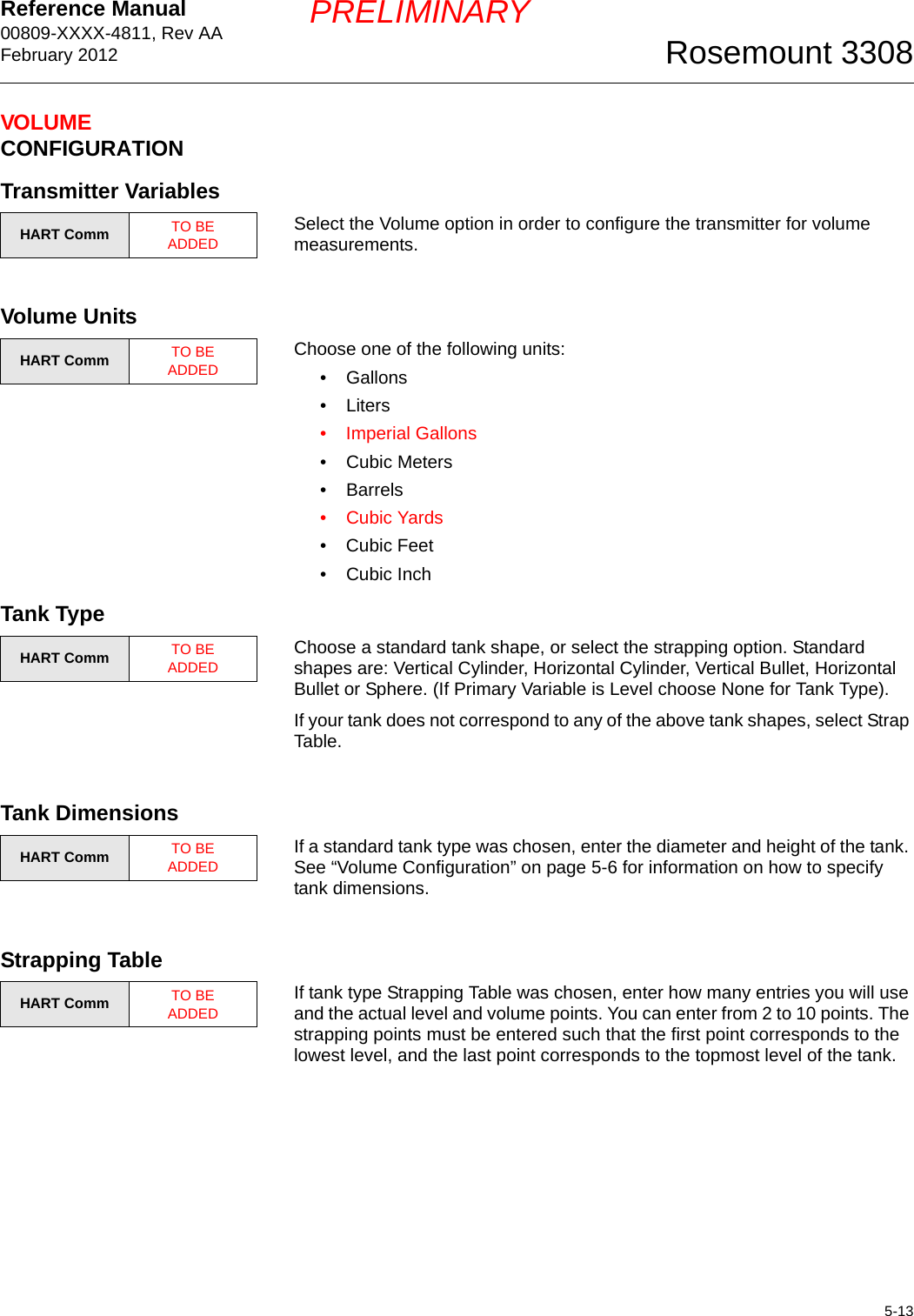
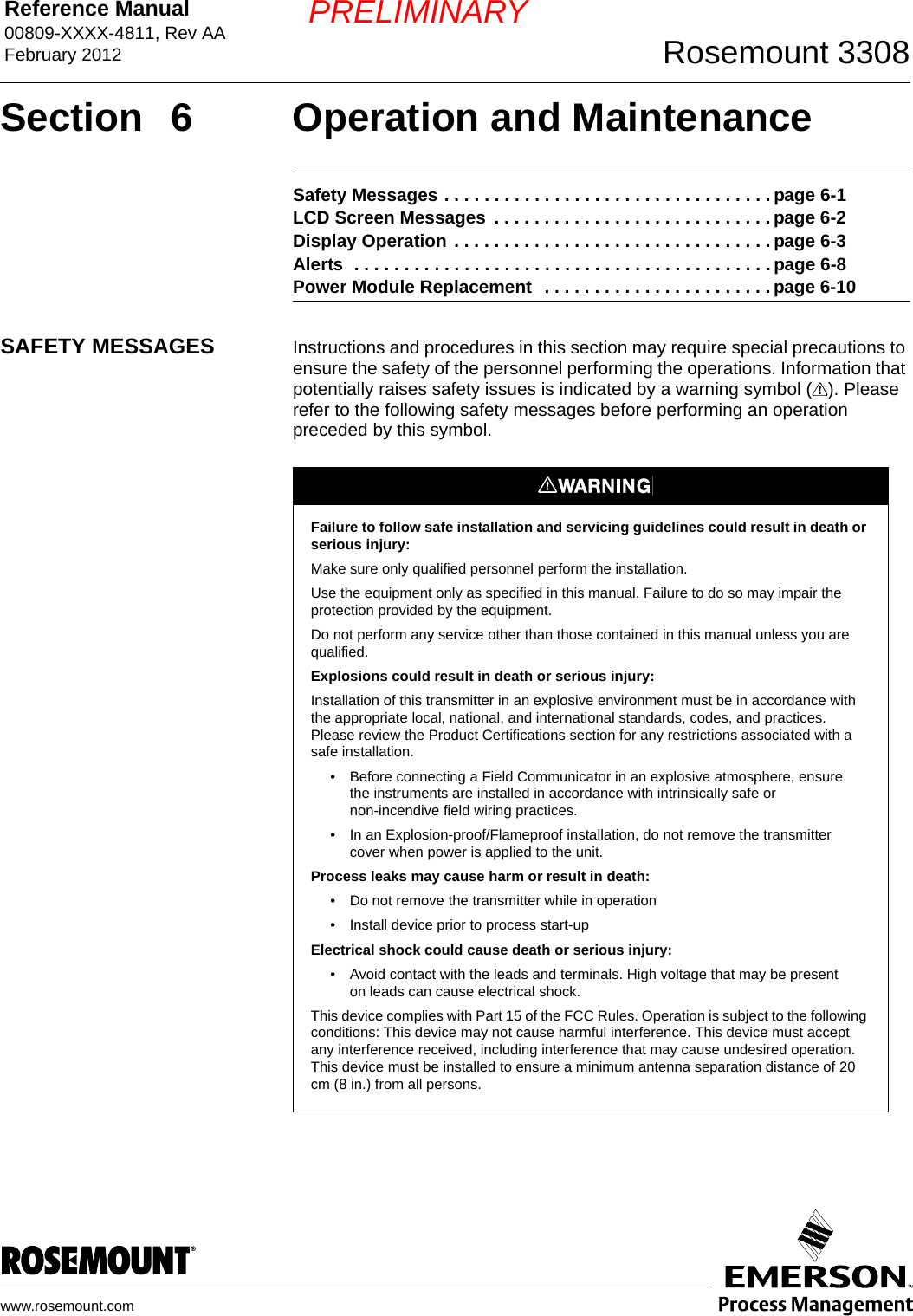
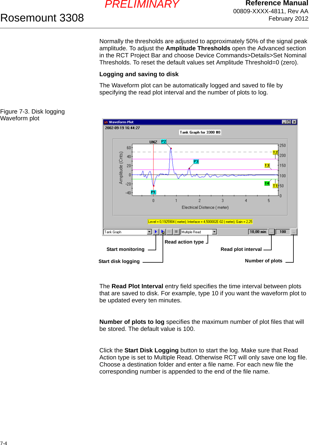
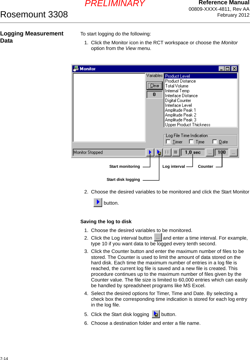
![Reference Manual 00809-XXXX-4811, Rev AAFebruary 20127-7Rosemount 3308PRELIMINARYHigh Level Rates The measurement signal is filtered in order to minimize the influence of disturbing noise. In most measurement situations this does not have a noticeable effect on the response time to level changes. If high level rates occur it may however be necessary to reduce the damping value in order to allow the transmitter to respond quicker. If there is too much noise the damping value may be increased in order to get a stable measurement signal.You can use the RCT software or a Field Communicator to change the Damping value. For the HART Communicator use the key sequence [1, 3, 5]. In the RCT software open the Setup>Output tab and enter the desired Damping value:The Damping parameter determines how quickly the transmitter responds to level changes and how robust the measurement signal is against noise. Technically, a damping value of 10 means that in 10 seconds the output from the transmitter is about 63% of the new level value. Consequently, when there are rapid level changes in the tank, it may be necessary to decrease the Damping value for the transmitter to be able to track the surface. On the other hand, in noisy environments, and if level rates are low, it may be better to increase the damping value to have a stable output signal.DampingOutput tab](https://usermanual.wiki/Rosemount/3308A/User-Guide-1654908-Page-87.png)
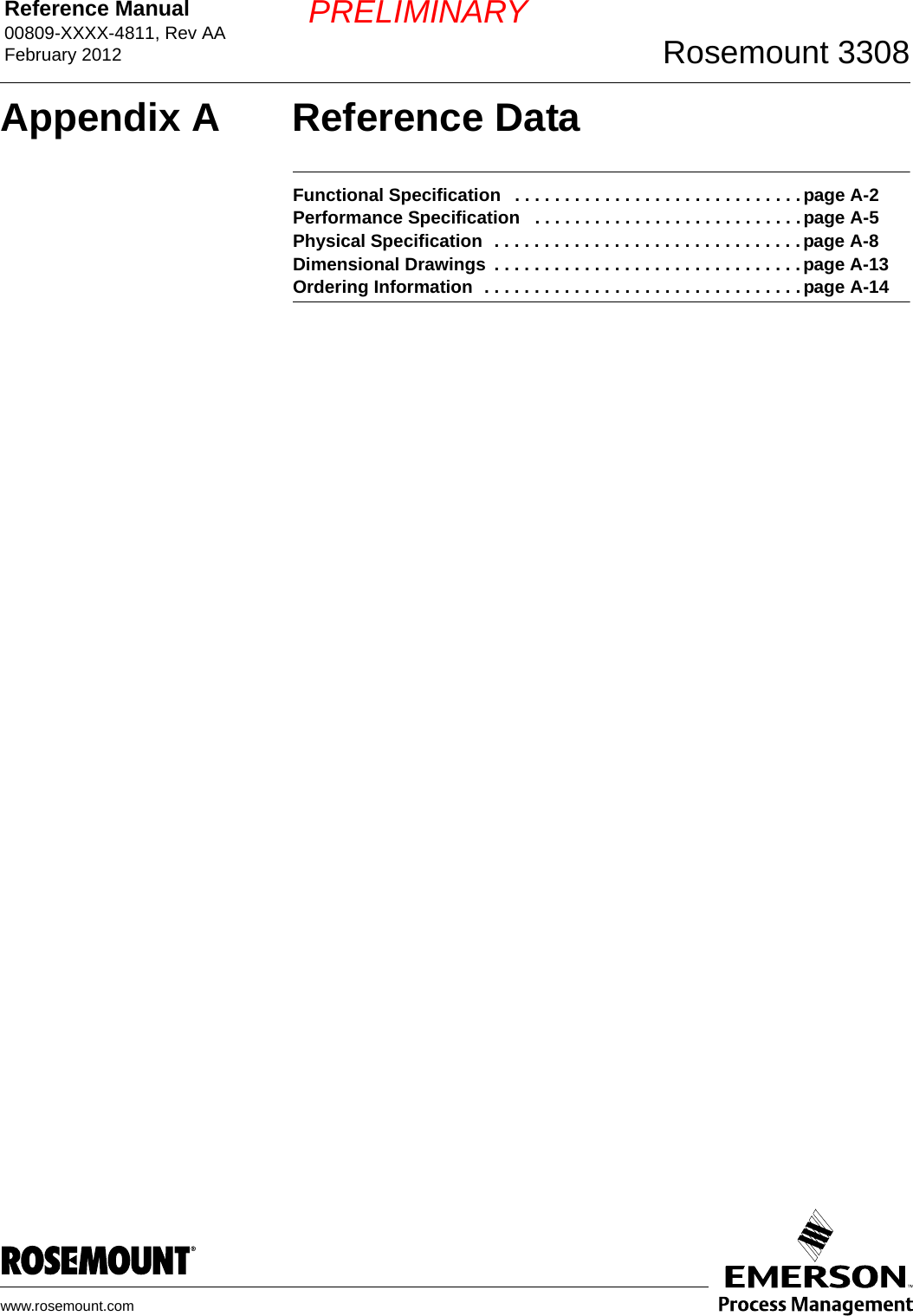
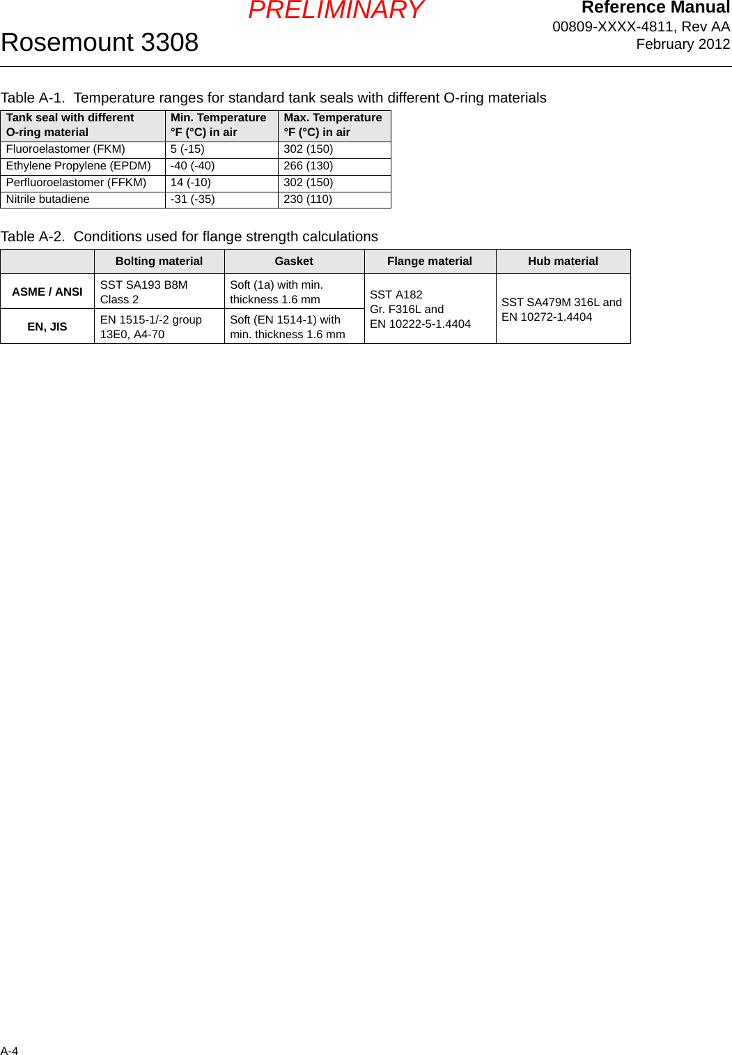
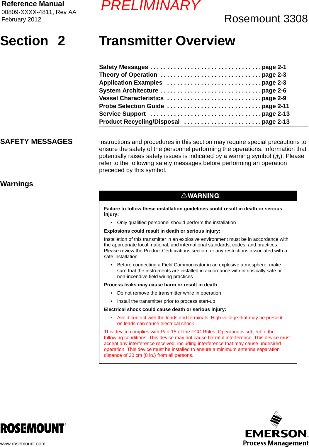
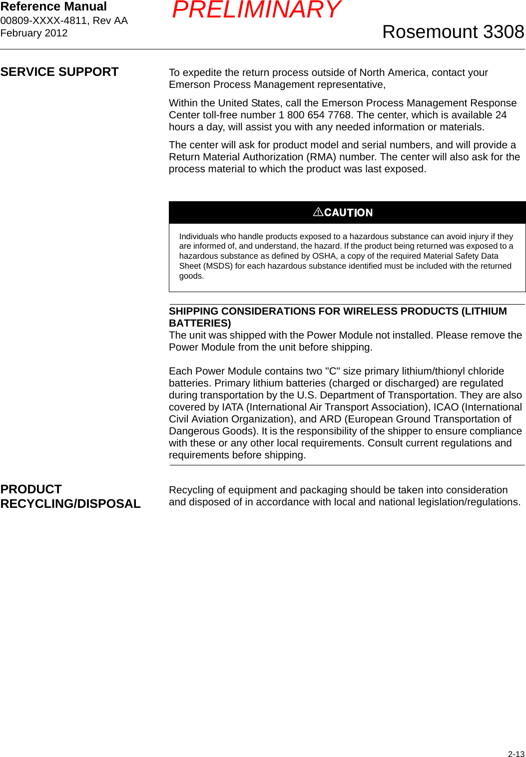
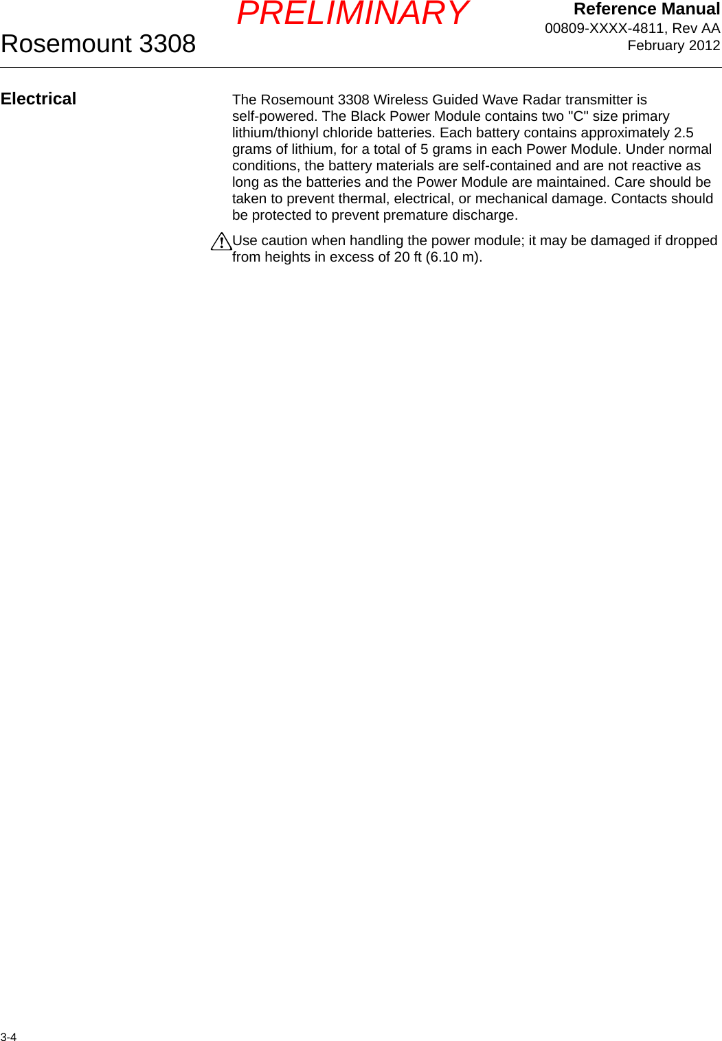
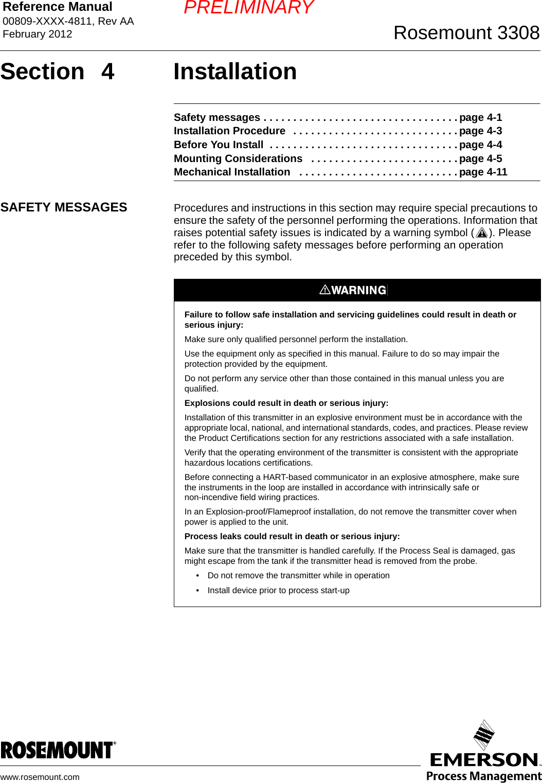
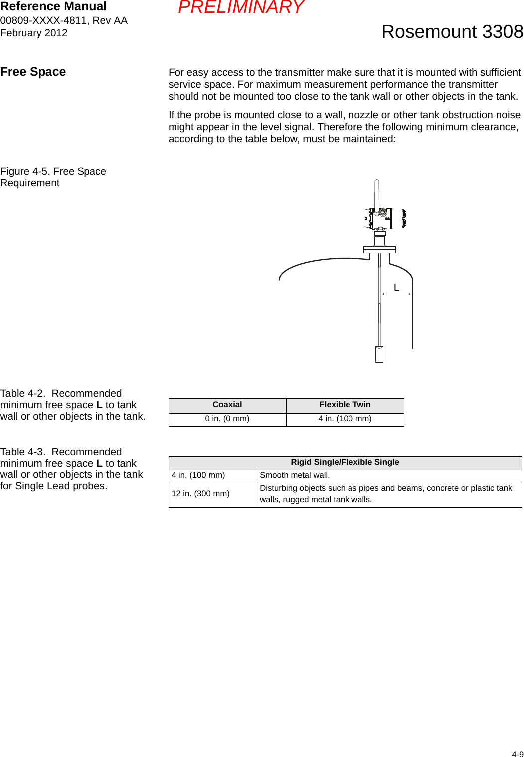
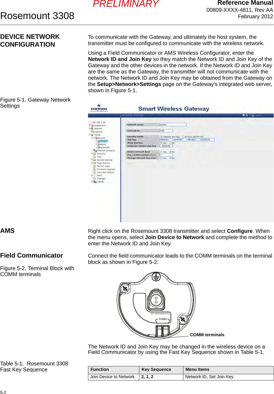
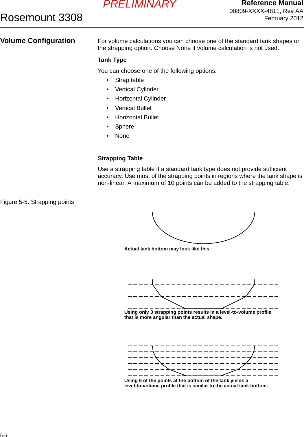
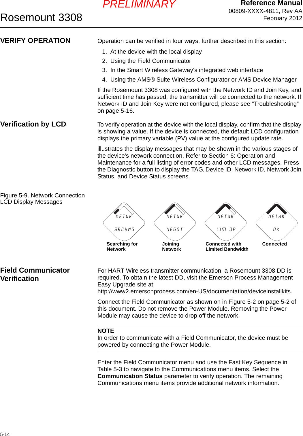
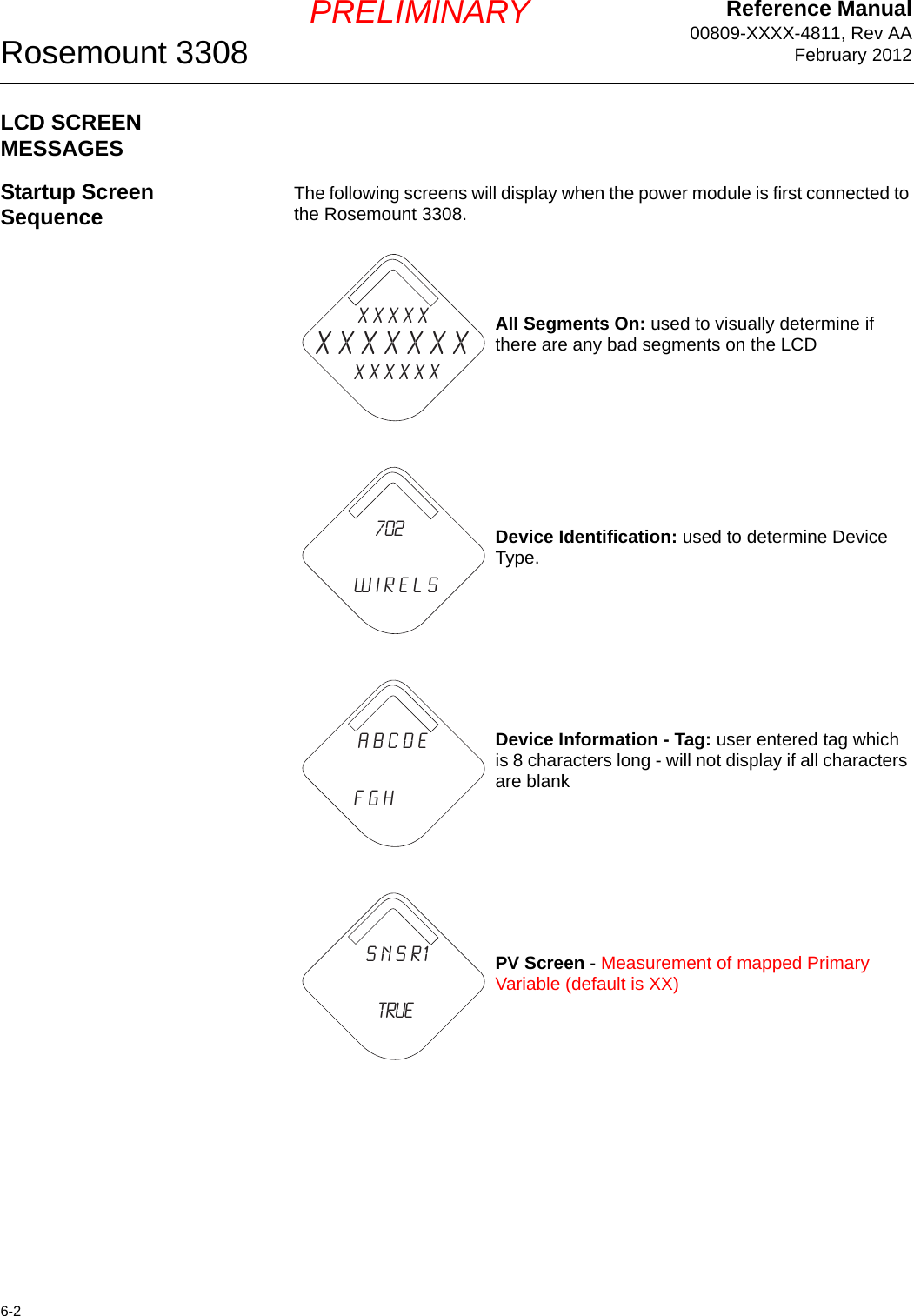
![Reference Manual00809-XXXX-4811, Rev AAFebruary 2012Rosemount 33087-8PRELIMINARYInterface Measurements with Fully Immersed ProbesThe Rosemount 3308 transmitter has a measurement option which makes it possible to handle interface measurements when the product level is not visible, for example in a full bridle pipe as illustrated in Figure 7-6. In this case the probe is fully immersed into the upper product, and only the interface level is detected by the transmitter. Even if the upper product level drops, it is ignored by the transmitter which continues to measure only the interface level, but the measurement accuracy is reduced since the transmitter does not take into account the influence of the air gap above the product surface. The Measurement Mode parameter is available via the HART command [1, 3, 3, 4]. Choose the Interface when Immersed Probe option.Measurement mode Interface when Immersed Probe can also be activated in the RCT software:1. Open the Setup window.2. Select the Tank Config tab.3. Choose Measurement Mode Interface when Immersed Probe.4. Click the Send Page button.NOTE!Do not use Measurement Mode Interface when Immersed Probe in “standard” applications when both Interface Level and Product Level are measured.If the product level drops, the air filled region in the upper part of the pipe will slightly reduce the measurement accuracy of the interface level. To achieve high accuracy in this measurement mode the probe must be fully immersed.Figure 7-6. Interface Level measurements in a full bridle pipe.NOTE!Adjust Threshold T2 if the level pulse is not detected.Interface DistanceInterface LevelProduct Level is ignoredInterface Level is measured](https://usermanual.wiki/Rosemount/3308A/User-Guide-1654908-Page-88.png)
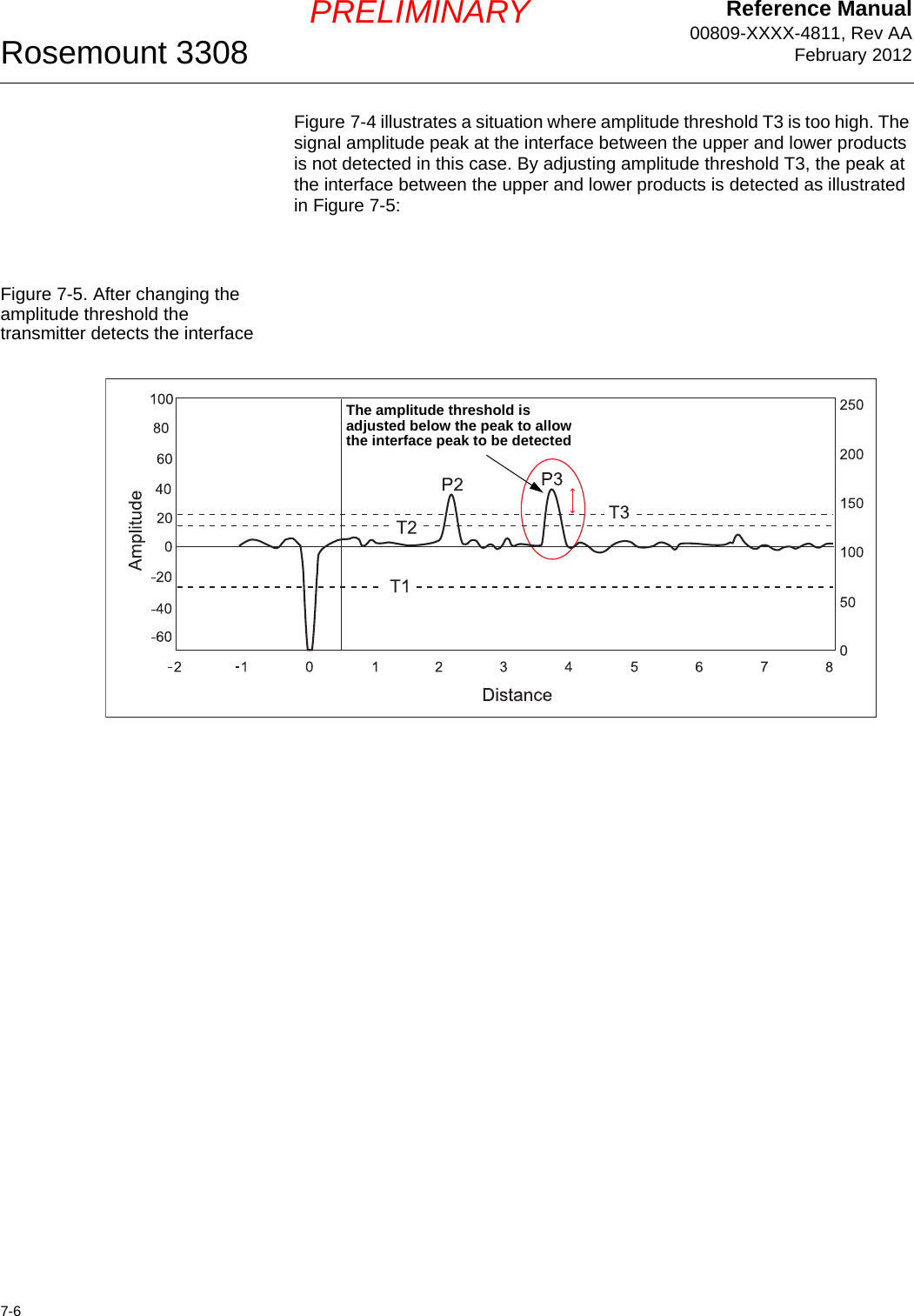
![Reference Manual 00809-XXXX-4811, Rev AAFebruary 20127-9Rosemount 3308PRELIMINARYSERVICELevel and Distance Calibration When calibrating the transmitter it is important that the product surface is calm and that the tank is not being filled or emptied.A complete calibration is performed in two steps:1. Calibrate the Distance measurement by adjusting the Calibration Offset parameter.2. Calibrate the Level measurement by adjusting the Tank Height.Distance calibration1. Measure the actual distance between the Upper Reference Point and the product surface.2. Adjust the Calibration Offset so that the Distance measured by the transmitter corresponds to the actual distance. The Calibration Offset parameter is available via HART command [1, 4, 5, 5],orRCT: open the Advanced section in the Project Bar and choose Device Commands>Basics>Set Calibration Offset.Level calibration1. Measure the actual Product Level.2. Adjust the Tank Height so that the measured Product Level corresponds with the actual level.Figure 7-7. Distance and Level calibrationLevelReference PointTank HeightDistanceReference Point](https://usermanual.wiki/Rosemount/3308A/User-Guide-1654908-Page-89.png)
![Reference Manual 00809-XXXX-4811, Rev AAFebruary 20127-11Rosemount 3308PRELIMINARYTo set the Upper Null Zone do one of the following:1. Select the HART command [1, 3, 3, 1].2. Enter the desired value, or1. Start the Radar Configuration Tool (RCT).2. Click the Setup icon in the RCT workspace Project Bar.3. Choose the Tank Config tab in the Setup window.4. Click the Receive Page button.5. Type the desired value in the Upper Null Zone field.6. Click the Send Page button. Now the Upper Null Zone is stored in the transmitter memory.Figure 7-8. Upper Null ZoneFigure 7-9. Identifying the Upper Null Zone in the RCT Waveform PlotTank HeightUpper Null ZoneProduct LevelUpper Reference Point--Upper Null ZoneDisturbance](https://usermanual.wiki/Rosemount/3308A/User-Guide-1654908-Page-91.png)
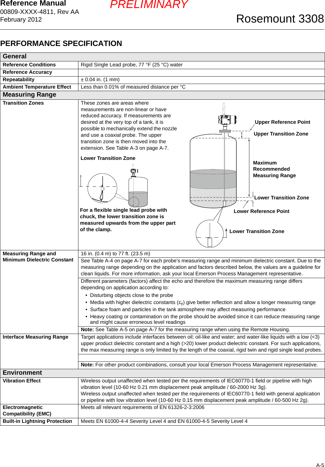
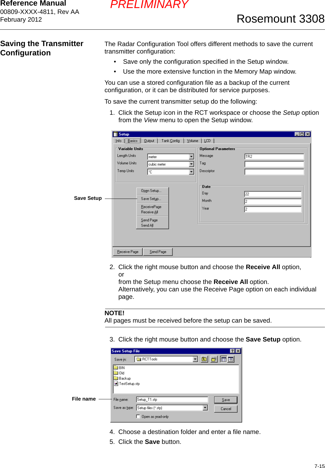
![Reference Manual 00809-XXXX-4811, Rev AAFebruary 20127-13Rosemount 3308PRELIMINARYBy adjusting the amplitude threshold T2 the product surface is detected correctly as illustrated in Figure 7-12.Figure 7-12. Waveform plot after threshold T2 was adjusted To adjust the amplitude thresholds select HART command [1, 4, 5, 3] or1. Start the Radar Configuration Tool (RCT).2. Choose the Device Commands option from the View menu.3. Open the Details folder.4. Click the Set Nominal Thresholds option.The thresholds T2 and T3 should be set to about 50% of the measured signal amplitude for the product surface and the interface peaks, respectively. NOTEAmplitude thresholds should not be set to values less than 3.NOTECheck that the dielectric constant parameter setting is reasonably close to the actual dielectric constant value of the upper product before changing the amplitude thresholds.NOTEDefault Amplitude thresholds can be set by typing 0 as the new threshold value.P1P2T1T2T3Amplitude1008060-6040-4020-200100500150200250 After T2 is adjusted the product surface is correctly detected](https://usermanual.wiki/Rosemount/3308A/User-Guide-1654908-Page-93.png)
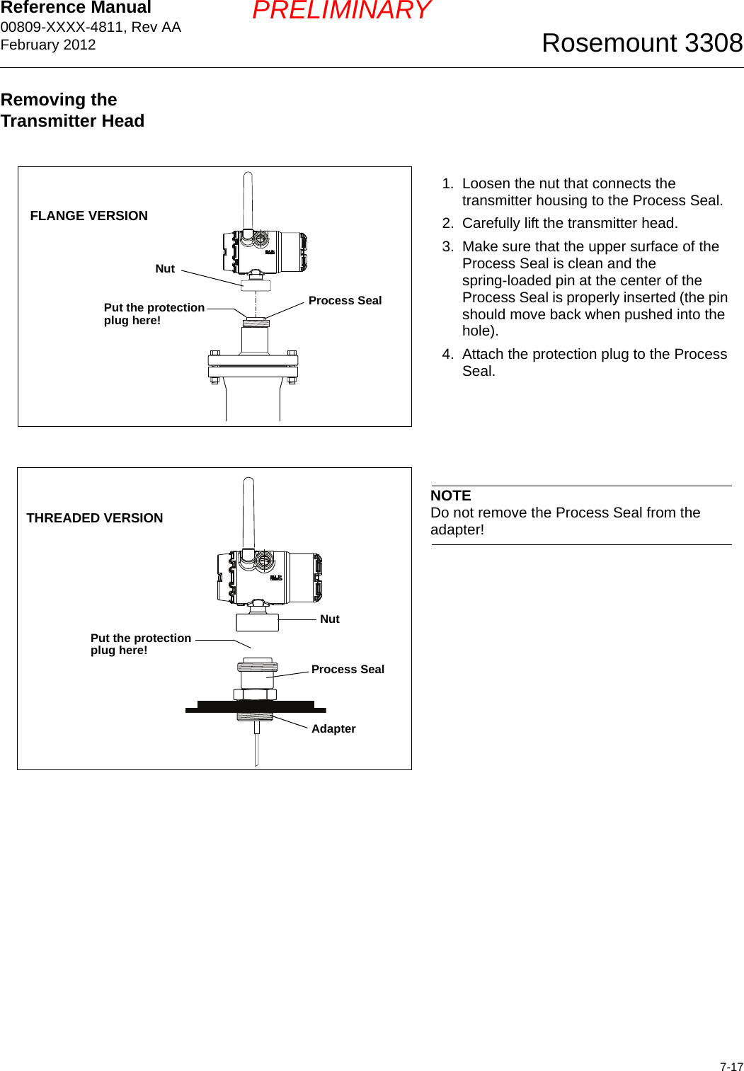
![Reference Manual00809-XXXX-4811, Rev AAFebruary 2012Rosemount 33087-18PRELIMINARYChanging the Probe1. Loosen the nut.2. Remove the transmitter head from the old probe.3. On the new probe, make sure that the protection plug is removed and the upper surface of the Process Seal is clean. Also make sure that the spring-loaded pin at the center of the Process Seal is properly inserted.4. Mount the transmitter head on the new probe.5. Fasten the nut again.6. If the new probe is not of the same type as the old one, update the transmitter configuration by setting the Probe Type parameter to the appropriate value: HART Fast Key sequence [1, 3, 2, 3],orRCT Setup/Tank Config.7. Measure the probe length and enter the measured value:HART Fast Key sequence [1, 3, 2, 2],orRCT Setup/Tank Config.8. Verify that the transmitter is calibrated.NutProbeTransmitter headProcess Seal](https://usermanual.wiki/Rosemount/3308A/User-Guide-1654908-Page-98.png)