Rosemount 3308A Wireless Guided Wave Radar Level Transmitter User Manual Book 3300 DA
Rosemount Inc Wireless Guided Wave Radar Level Transmitter Book 3300 DA
User Manual

www.rosemount.com
Reference Manual
00809-XXXX-4811, Rev AA
February 2012
PRELIMINARY
Rosemount 3308
Wireless Guided Wave Radar Level Transmitter
PRELIMINARY
Reference Manual
00809-XXXX-4811, Rev AA
February 2012 Rosemount 3308
www.rosemount.com
PRELIMINARY
Rosemount 3308
Wireless Guided Wave Radar
Level Transmitter
Rosemount 3308 Hardware Revision
HART® Device Revision
Field Communicator Field Device Revision
1
1
Dev v1, DD v1
NOTICE
Read this manual before working with the product. For personal and system safety, and for
optimum product performance, make sure you thoroughly understand the contents before
installing, using, or maintaining this product.
The United States has two toll-free assistance numbers and one international number.
Customer Central
1-800-999-9307 (7:00 a.m. to 7:00 p.m. CST)
North American Response Center
1-800-654-7768 (24 hours a day)
Equipment service needs
International
1-952-906-8888
The products described in this document are NOT designed for nuclear-qualified
applications.
Using non-nuclear qualified products in applications that require nuclear-qualified hardware
or products may cause inaccurate readings.
For information on Rosemount nuclear-qualified products, contact your local Emerson
Process Management Sales Representative.
NOTICE
The Rosemount 3308 and all other wireless devices should be installed only after the Smart
Wireless Gateway has been installed and is functioning properly. Wireless devices should
also be powered up in order of proximity from the Smart Wireless Gateway, beginning with
the closest. This will result in a simpler and faster network installation.

PRELIMINARY
Failure to follow these installation guidelines could result in death or serious injury:
• Only qualified personnel should perform the installation
Explosions could result in death or serious injury:
Installation of this transmitter in an explosive environment must be in accordance with the
appropriate local, national, and international standards, codes, and practices. Please review
the Product Certifications section for any restrictions associated with a safe installation.
• Before connecting a Field Communicator in an explosive atmosphere, ensure the
instruments are installed in accordance with intrinsically safe or non-incendive field
wiring practices
Process leaks may cause harm or result in death:
• Do not remove the transmitter while in operation
• Install device prior to process start-up
• Install and tighten process connectors before applying pressure
Electrical shock can result in death or serious injury:
• Avoid contact with the leads and terminals. High voltage that may be present on
leads can cause electrical shock
This device complies with Part 15 of the FCC Rules. Operation is subject to the following
conditions: This device may not cause harmful interference. This device must accept any
interference received, including interference that may cause undesired operation. This
device must be installed to ensure a minimum antenna separation distance of 20 cm (8 in.)
from all persons.
NOTICE
Power Module Considerations
Each Power Module contains two "C" size primary lithium/thionyl chloride batteries. Each
battery contains approximately 2.5 grams of lithium, for a total of 5 grams in each pack.
Under normal conditions, the battery materials are self-contained and are not reactive as
long as the batteries and the pack integrity are maintained. Care should be taken to prevent
thermal, electrical or mechanical damage. Contacts should be protected to prevent
premature discharge.
Battery hazards remain when cells are discharged.
Power modules should be stored in a clean and dry area. For maximum battery life, storage
temperature should not exceed 30° C.
The Power Module may be replaced in a hazardous area. The Power Module has surface
resistivity greater than one gigaohm and must be properly installed in the wireless device
enclosure. Care must be taken during transportation to and from the point of installation to
prevent electrostatic charge build-up.
NOTICE
Shipping considerations for wireless products
The unit was shipped to you without the Power Module installed. Please remove the Power
Module prior to shipping the unit.
Each Power Module contains two "C" size primary lithium/thionyl chloride batteries. Primary
lithium batteries are regulated in transportation by the U.S. Department of Transportation,
and are also covered by IATA (International Air Transport Association), ICAO (International
Civil Aviation Organization), and ARD (European Ground Transportation of Dangerous
Goods). It is the responsibility of the shipper to ensure compliance with these or any other
local requirements. Please consult current regulations and requirements before shipping

Reference Manual
00809-XXXX-4811, Rev AA
February 2012 Rosemount 3308
www.rosemount.com
PRELIMINARY
Table of Contents
SECTION 1
Introduction Safety Messages . . . . . . . . . . . . . . . . . . . . . . . . . . . . . . . . . . . . . . . . . 1-1
Manual Overview . . . . . . . . . . . . . . . . . . . . . . . . . . . . . . . . . . . . . . . . . 1-2
Service Support . . . . . . . . . . . . . . . . . . . . . . . . . . . . . . . . . . . . . . . . . . 1-3
Product Recycling/Disposal. . . . . . . . . . . . . . . . . . . . . . . . . . . . . . . . . 1-3
SECTION 2
Transmitter Overview Safety Messages . . . . . . . . . . . . . . . . . . . . . . . . . . . . . . . . . . . . . . . . . 2-1
Warnings . . . . . . . . . . . . . . . . . . . . . . . . . . . . . . . . . . . . . . . . . . . . 2-1
Rosemount 3308 . . . . . . . . . . . . . . . . . . . . . . . . . . . . . . . . . . . . . . . . . 2-2
Theory of Operation. . . . . . . . . . . . . . . . . . . . . . . . . . . . . . . . . . . . . . . 2-3
Application Examples . . . . . . . . . . . . . . . . . . . . . . . . . . . . . . . . . . . . . 2-3
System Architecture. . . . . . . . . . . . . . . . . . . . . . . . . . . . . . . . . . . . . . . 2-6
Interface . . . . . . . . . . . . . . . . . . . . . . . . . . . . . . . . . . . . . . . . . . . . . 2-7
Vessel Characteristics . . . . . . . . . . . . . . . . . . . . . . . . . . . . . . . . . . . . . 2-9
Heating Coils, Agitators . . . . . . . . . . . . . . . . . . . . . . . . . . . . . . . . . 2-9
Tank Shape . . . . . . . . . . . . . . . . . . . . . . . . . . . . . . . . . . . . . . . . . . 2-9
Components of the Transmitter . . . . . . . . . . . . . . . . . . . . . . . . . . . . . 2-10
Probe Selection Guide. . . . . . . . . . . . . . . . . . . . . . . . . . . . . . . . . . . . 2-11
Transition Zones. . . . . . . . . . . . . . . . . . . . . . . . . . . . . . . . . . . . . . 2-12
Service Support . . . . . . . . . . . . . . . . . . . . . . . . . . . . . . . . . . . . . . . . . 2-13
Product Recycling/Disposal. . . . . . . . . . . . . . . . . . . . . . . . . . . . . . . . 2-13
SECTION 3
Wireless Configuration Safety Messages . . . . . . . . . . . . . . . . . . . . . . . . . . . . . . . . . . . . . . . . . 3-1
Warnings . . . . . . . . . . . . . . . . . . . . . . . . . . . . . . . . . . . . . . . . . . . . 3-1
Wireless Considerations . . . . . . . . . . . . . . . . . . . . . . . . . . . . . . . . . . . 3-2
General. . . . . . . . . . . . . . . . . . . . . . . . . . . . . . . . . . . . . . . . . . . . . . 3-2
Mechanical . . . . . . . . . . . . . . . . . . . . . . . . . . . . . . . . . . . . . . . . . . . 3-3
Electrical. . . . . . . . . . . . . . . . . . . . . . . . . . . . . . . . . . . . . . . . . . . . . 3-4
Power Module Installation . . . . . . . . . . . . . . . . . . . . . . . . . . . . . . . . . . 3-5
Device Configuration . . . . . . . . . . . . . . . . . . . . . . . . . . . . . . . . . . . . . . 3-6
Device Network Configuration . . . . . . . . . . . . . . . . . . . . . . . . . . . . . . . 3-6
AMS . . . . . . . . . . . . . . . . . . . . . . . . . . . . . . . . . . . . . . . . . . . . . . . . 3-7
Field Communicator . . . . . . . . . . . . . . . . . . . . . . . . . . . . . . . . . . . . 3-7
Fast Key Sequences . . . . . . . . . . . . . . . . . . . . . . . . . . . . . . . . . . . 3-7
Remove Power Module . . . . . . . . . . . . . . . . . . . . . . . . . . . . . . . . . . . . 3-7
SECTION 4
Installation Safety messages . . . . . . . . . . . . . . . . . . . . . . . . . . . . . . . . . . . . . . . . . 4-1
Installation Procedure . . . . . . . . . . . . . . . . . . . . . . . . . . . . . . . . . . . . . 4-3
Before You Install . . . . . . . . . . . . . . . . . . . . . . . . . . . . . . . . . . . . . . . . 4-4
Software write protect. . . . . . . . . . . . . . . . . . . . . . . . . . . . . . . . . . . 4-4
Mounting Considerations. . . . . . . . . . . . . . . . . . . . . . . . . . . . . . . . . . . 4-5
Process Connection . . . . . . . . . . . . . . . . . . . . . . . . . . . . . . . . . . . . 4-5
Installation of Single Lead Probes in Non-metallic Tanks . . . . . . . 4-7
Mounting in Still pipes/by-pass pipes . . . . . . . . . . . . . . . . . . . . . . . 4-8

Reference Manual
00809-XXXX-4811, Rev AA
February 2012
Rosemount 3308
TOC-2
PRELIMINARY
Free Space. . . . . . . . . . . . . . . . . . . . . . . . . . . . . . . . . . . . . . . . . . . 4-9
Recommended Mounting Position . . . . . . . . . . . . . . . . . . . . . . . . 4-10
Mechanical Installation . . . . . . . . . . . . . . . . . . . . . . . . . . . . . . . . . . . 4-11
Shortening the Probe . . . . . . . . . . . . . . . . . . . . . . . . . . . . . . . . . . 4-13
Anchoring . . . . . . . . . . . . . . . . . . . . . . . . . . . . . . . . . . . . . . . . . . . 4-15
Mounting a Centering Disc for Pipe Installations . . . . . . . . . . . . . 4-17
LCD Display. . . . . . . . . . . . . . . . . . . . . . . . . . . . . . . . . . . . . . . . . . . . 4-18
General. . . . . . . . . . . . . . . . . . . . . . . . . . . . . . . . . . . . . . . . . . . . . 4-18
LCD Rotation . . . . . . . . . . . . . . . . . . . . . . . . . . . . . . . . . . . . . . . . 4-18
Retrofitting . . . . . . . . . . . . . . . . . . . . . . . . . . . . . . . . . . . . . . . . . . 4-18
LCD Configuration . . . . . . . . . . . . . . . . . . . . . . . . . . . . . . . . . . . . 4-18
Ground the Transmitter . . . . . . . . . . . . . . . . . . . . . . . . . . . . . . . . . . . 4-19
How to Ground the Device . . . . . . . . . . . . . . . . . . . . . . . . . . . . . . 4-19
SECTION 5
Start-Up/Commissioning Safety messages . . . . . . . . . . . . . . . . . . . . . . . . . . . . . . . . . . . . . . . . . 5-1
Device Network Configuration . . . . . . . . . . . . . . . . . . . . . . . . . . . . . . . 5-2
AMS . . . . . . . . . . . . . . . . . . . . . . . . . . . . . . . . . . . . . . . . . . . . . . . . 5-2
Field Communicator . . . . . . . . . . . . . . . . . . . . . . . . . . . . . . . . . . . . 5-2
Configuration Parameters . . . . . . . . . . . . . . . . . . . . . . . . . . . . . . . . . . 5-3
Basic Configuration . . . . . . . . . . . . . . . . . . . . . . . . . . . . . . . . . . . . 5-3
Volume Configuration. . . . . . . . . . . . . . . . . . . . . . . . . . . . . . . . . . . 5-6
Configuration using a Field Communicator . . . . . . . . . . . . . . . . . . . . . 5-8
Basic Configuration . . . . . . . . . . . . . . . . . . . . . . . . . . . . . . . . . . . . . . . 5-9
Transmitter Variables . . . . . . . . . . . . . . . . . . . . . . . . . . . . . . . . . . . 5-9
Measurement Units . . . . . . . . . . . . . . . . . . . . . . . . . . . . . . . . . . . . 5-9
Tank Height . . . . . . . . . . . . . . . . . . . . . . . . . . . . . . . . . . . . . . . . . . 5-9
Probe Length . . . . . . . . . . . . . . . . . . . . . . . . . . . . . . . . . . . . . . . . . 5-9
Probe Type. . . . . . . . . . . . . . . . . . . . . . . . . . . . . . . . . . . . . . . . . . 5-10
Product Dielectric . . . . . . . . . . . . . . . . . . . . . . . . . . . . . . . . . . . . . 5-10
Vapor Dielectric . . . . . . . . . . . . . . . . . . . . . . . . . . . . . . . . . . . . . . 5-10
Measurement Mode . . . . . . . . . . . . . . . . . . . . . . . . . . . . . . . . . . . 5-11
Probe Angle . . . . . . . . . . . . . . . . . . . . . . . . . . . . . . . . . . . . . . . . . 5-11
Maximum Upper Product Thickness. . . . . . . . . . . . . . . . . . . . . . . 5-11
Display . . . . . . . . . . . . . . . . . . . . . . . . . . . . . . . . . . . . . . . . . . . . . 5-11
Volume Configuration . . . . . . . . . . . . . . . . . . . . . . . . . . . . . . . . . . . . 5-13
Transmitter Variables . . . . . . . . . . . . . . . . . . . . . . . . . . . . . . . . . . 5-13
Volume Units . . . . . . . . . . . . . . . . . . . . . . . . . . . . . . . . . . . . . . . . 5-13
Tank Type. . . . . . . . . . . . . . . . . . . . . . . . . . . . . . . . . . . . . . . . . . . 5-13
Tank Dimensions . . . . . . . . . . . . . . . . . . . . . . . . . . . . . . . . . . . . . 5-13
Strapping Table . . . . . . . . . . . . . . . . . . . . . . . . . . . . . . . . . . . . . . 5-13
Verify Operation. . . . . . . . . . . . . . . . . . . . . . . . . . . . . . . . . . . . . . . . . 5-14
Verification by LCD. . . . . . . . . . . . . . . . . . . . . . . . . . . . . . . . . . . . 5-14
Field Communicator Verification. . . . . . . . . . . . . . . . . . . . . . . . . . 5-14
Verification by Gateway . . . . . . . . . . . . . . . . . . . . . . . . . . . . . . . . 5-15
Verification with AMS Wireless Configurator . . . . . . . . . . . . . . . . 5-15
Troubleshooting . . . . . . . . . . . . . . . . . . . . . . . . . . . . . . . . . . . . . . 5-16
SECTION 6
Operation and
Maintenance
Safety Messages . . . . . . . . . . . . . . . . . . . . . . . . . . . . . . . . . . . . . . . . . 6-1
LCD Screen Messages . . . . . . . . . . . . . . . . . . . . . . . . . . . . . . . . . . . . 6-2
Startup Screen Sequence . . . . . . . . . . . . . . . . . . . . . . . . . . . . . . . 6-2
Display Operation . . . . . . . . . . . . . . . . . . . . . . . . . . . . . . . . . . . . . . . . 6-3
Diagnostic Button Screen Sequence . . . . . . . . . . . . . . . . . . . . . . . 6-3

Reference Manual
00809-XXXX-4811, Rev AA
February 2012
TOC-3
Rosemount 3308
PRELIMINARY
Network Connection Status Screens . . . . . . . . . . . . . . . . . . . . . . . 6-5
Diagnostic Button Screen Sequence (continued). . . . . . . . . . . . . . 6-6
Alerts . . . . . . . . . . . . . . . . . . . . . . . . . . . . . . . . . . . . . . . . . . . . . . . . . . 6-8
Device Alert Configuration . . . . . . . . . . . . . . . . . . . . . . . . . . . . . . . 6-9
Power Module Replacement . . . . . . . . . . . . . . . . . . . . . . . . . . . . . . . 6-10
SECTION 7
Service and
Troubleshooting
Safety messages . . . . . . . . . . . . . . . . . . . . . . . . . . . . . . . . . . . . . . . . . 7-1
Advanced Configuration . . . . . . . . . . . . . . . . . . . . . . . . . . . . . . . . . . . 7-2
User defined Upper Reference Point . . . . . . . . . . . . . . . . . . . . . . . 7-2
Plotting the Measurement Signal . . . . . . . . . . . . . . . . . . . . . . . . . . 7-3
Interface Measurements for Semi-Transparent Bottom Products . 7-5
High Level Rates . . . . . . . . . . . . . . . . . . . . . . . . . . . . . . . . . . . . . . 7-7
Interface Measurements with Fully Immersed Probes . . . . . . . . . . 7-8
Service. . . . . . . . . . . . . . . . . . . . . . . . . . . . . . . . . . . . . . . . . . . . . . . . . 7-9
Level and Distance Calibration. . . . . . . . . . . . . . . . . . . . . . . . . . . . 7-9
Disturbances at the Top of the Tank . . . . . . . . . . . . . . . . . . . . . . 7-10
Amplitude Threshold Settings. . . . . . . . . . . . . . . . . . . . . . . . . . . . 7-12
Logging Measurement Data . . . . . . . . . . . . . . . . . . . . . . . . . . . . . 7-14
Saving the Transmitter Configuration. . . . . . . . . . . . . . . . . . . . . . 7-15
Removing the Transmitter Head. . . . . . . . . . . . . . . . . . . . . . . . . . 7-17
Changing the Probe . . . . . . . . . . . . . . . . . . . . . . . . . . . . . . . . . . . 7-18
Diagnostic Messages. . . . . . . . . . . . . . . . . . . . . . . . . . . . . . . . . . . . . 7-19
Troubleshooting . . . . . . . . . . . . . . . . . . . . . . . . . . . . . . . . . . . . . . 7-19
Errors . . . . . . . . . . . . . . . . . . . . . . . . . . . . . . . . . . . . . . . . . . . . . . 7-20
Warnings . . . . . . . . . . . . . . . . . . . . . . . . . . . . . . . . . . . . . . . . . . . 7-21
APPENDIX A
Reference Data
APPENDIX B
Product Certifications Safety Messages . . . . . . . . . . . . . . . . . . . . . . . . . . . . . . . . . . . . . . . . . B-1

Reference Manual
00809-XXXX-4811, Rev AA
February 2012
Rosemount 3308
TOC-4
PRELIMINARY
Reference Manual
00809-XXXX-4811, Rev AA
February 2012 Rosemount 3308
www.rosemount.com
PRELIMINARY
Section 1 Introduction
Safety Messages . . . . . . . . . . . . . . . . . . . . . . . . . . . . . . . . . page 1-1
Manual Overview . . . . . . . . . . . . . . . . . . . . . . . . . . . . . . . . page 1-2
Service Support . . . . . . . . . . . . . . . . . . . . . . . . . . . . . . . . . page 1-3
Product Recycling/Disposal . . . . . . . . . . . . . . . . . . . . . . . page 1-3
SAFETY MESSAGES Procedures and instructions in this manual may require special precautions to
ensure the safety of the personnel performing the operations. Information that
raises potential safety issues is indicated by a warning symbol ( ). Refer to
the safety messages listed at the beginning of each section before performing
an operation preceded by this symbol.
Failure to follow these installation guidelines could result in death or serious
injury.
• Make sure only qualified personnel perform the installation.
• Use the equipment only as specified in this manual. Failure to do so may
impair the protection provided by the equipment.
Explosions could result in death or serious injury.
• Verify that the operating environment of the transmitter is consistent with the
appropriate hazardous locations certifications.
• Before connecting a HART®-based communicator in an explosive atmosphere,
make sure the instruments in the loop are installed in accordance with
intrinsically safe or non-incendive field wiring practices.
Electrical shock could cause death or serious injury.
• Use extreme caution when making contact with the leads and terminals.
Any substitution of non-recognized parts may jeopardize safety. Repair, e.g. substitution
of components etc., may also jeopardize safety and is under no circumstances allowed.

Reference Manual
00809-XXXX-4811, Rev AA
February 2012
Rosemount 3308
1-2
PRELIMINARY
MANUAL OVERVIEW This manual provides installation, configuration and maintenance information
for the Rosemount 3308 transmitter.
Section 2: Transmitter Overview
• Theory of operation
• Application examples
• System architecture
• Process and vessel characteristics
• Description of the transmitter
Section 3: Wireless Configuration
• Mounting considerations
• Mechanical installation
• Electrical installation
Section 4: Installation
• Mounting considerations
• Mechanical installation
• Electrical installation
Section 5: Start-Up/Commissioning
• Configuration instructions
• Configuration using the HART Communicator
• Configuration using the RCT software
Section 6: Operation and Maintenance
• Display functionality
• Error messages
• Alarm and write protection
Section 7: Service and Troubleshooting
• Advanced configuration
•Service
• Diagnostic messages
Appendix A: Reference Data
• Specifications
• Ordering Information
Appendix B: Product Certifications
• Examples of labels
•EU conformity
• European ATEX Directive information
• FM approvals
• CSA approvals
• Approval drawings
Reference Manual
00809-XXXX-4811, Rev AA
February 2012
1-3
Rosemount 3308
PRELIMINARY
SERVICE SUPPORT To expedite the return process outside of the United States, contact the
nearest Emerson Process Management representative.
Within the United States, call the Emerson Process Management Instrument
and Valves Response Center using the 1-800-654-RSMT (7768) toll-free
number. This center, available 24 hours a day, will assist you with any needed
information or materials.
The center will ask for product model and serial numbers, and will provide a
Return Material Authorization (RMA) number. The center will also ask for the
process material to which the product was last exposed.
Emerson Process Management Instrument and Valves Response Center
representatives will explain the additional information and procedures
necessary to return goods exposed to hazardous substances.
PRODUCT
RECYCLING/DISPOSAL Recycling of equipment and packaging should be taken into consideration
and disposed of in accordance with local and national legislation/regulations.
Individuals who handle products exposed to a hazardous substance can avoid injury if
they are informed of and understand the hazard. If the product being returned was
exposed to a hazardous substance as defined by Occupational Safety and Health
Administration (OSHA), a copy of the required Material Safety Data Sheet (MSDS) for
each hazardous substance identified must be included with the returned goods.

Reference Manual
00809-XXXX-4811, Rev AA
February 2012
Rosemount 3308
1-4
PRELIMINARY
Reference Manual
00809-XXXX-4811, Rev AA
February 2012 Rosemount 3308
www.rosemount.com
PRELIMINARY
Section 2 Transmitter Overview
Safety Messages . . . . . . . . . . . . . . . . . . . . . . . . . . . . . . . . . page 2-1
Theory of Operation . . . . . . . . . . . . . . . . . . . . . . . . . . . . . . page 2-3
Application Examples . . . . . . . . . . . . . . . . . . . . . . . . . . . . page 2-3
System Architecture . . . . . . . . . . . . . . . . . . . . . . . . . . . . . . page 2-6
Vessel Characteristics . . . . . . . . . . . . . . . . . . . . . . . . . . . . page 2-9
Probe Selection Guide . . . . . . . . . . . . . . . . . . . . . . . . . . . . page 2-11
Service Support . . . . . . . . . . . . . . . . . . . . . . . . . . . . . . . . . page 2-13
Product Recycling/Disposal . . . . . . . . . . . . . . . . . . . . . . . page 2-13
SAFETY MESSAGES Instructions and procedures in this section may require special precautions to
ensure the safety of the personnel performing the operations. Information that
potentially raises safety issues is indicated by a warning symbol ( ). Please
refer to the following safety messages before performing an operation
preceded by this symbol.
Warnings
Failure to follow these installation guidelines could result in death or serious
injury:
• Only qualified personnel should perform the installation
Explosions could result in death or serious injury:
Installation of this transmitter in an explosive environment must be in accordance with
the appropriate local, national, and international standards, codes, and practices.
Please review the Product Certifications section for any restrictions associated with a
safe installation.
• Before connecting a Field Communicator in an explosive atmosphere, make
sure that the instruments are installed in accordance with intrinsically safe or
non-incendive field wiring practices
Process leaks may cause harm or result in death:
• Do not remove the transmitter while in operation
• Install the transmitter prior to process start-up
Electrical shock could cause death or serious injury:
• Avoid contact with the leads and terminals. High voltage that may be present
on leads can cause electrical shock
This device complies with Part 15 of the FCC Rules. Operation is subject to the
following conditions: This device may not cause harmful interference. This device must
accept any interference received, including interference that may cause undesired
operation. This device must be installed to ensure a minimum antenna separation
distance of 20 cm (8 in.) from all persons.
Reference Manual
00809-XXXX-4811, Rev AA
February 2012
Rosemount 3308
2-2
PRELIMINARY
ROSEMOUNT 3308 Features of the Rosemount 3308 Wireless Guided Wave Radar include:
• An installation-ready solution that provides a variety of mounting
options, transmitter configurations, and switches
• Flexibility to meet your most demanding applications
• Wireless output with >99% data reliability delivers rich HART® data,
protected by industry leading security
• Single or dual switch input with logic for limit contact and opposing
contact applications
• The integral LCD conveniently displays the primary switch input and
diagnostics of the transmitter
• Simple and easy installation practices currently being used for robust
installations
Smart Wireless delivers innovative wireless solutions for level measurement
and overall transmitter performance
• Self-organizing network delivers information rich data with >99% data
reliability and establishes a highly stable network
• Smart Wireless capabilities extend the full benefits of PlantWeb® to
previously inaccessible temperature measurement locations
• Emerson SmartPower™ Solutions provide an intrinsically safe Power
Module, allowing field replacements without removing the transmitter
from the process, keeping personnel safe, and reducing maintenance
costs
• Emerson Process Management's layered approach to wireless network
security ensures that data transmissions are secure
Reference Manual
00809-XXXX-4811, Rev AA
February 2012
2-3
Rosemount 3308
PRELIMINARY
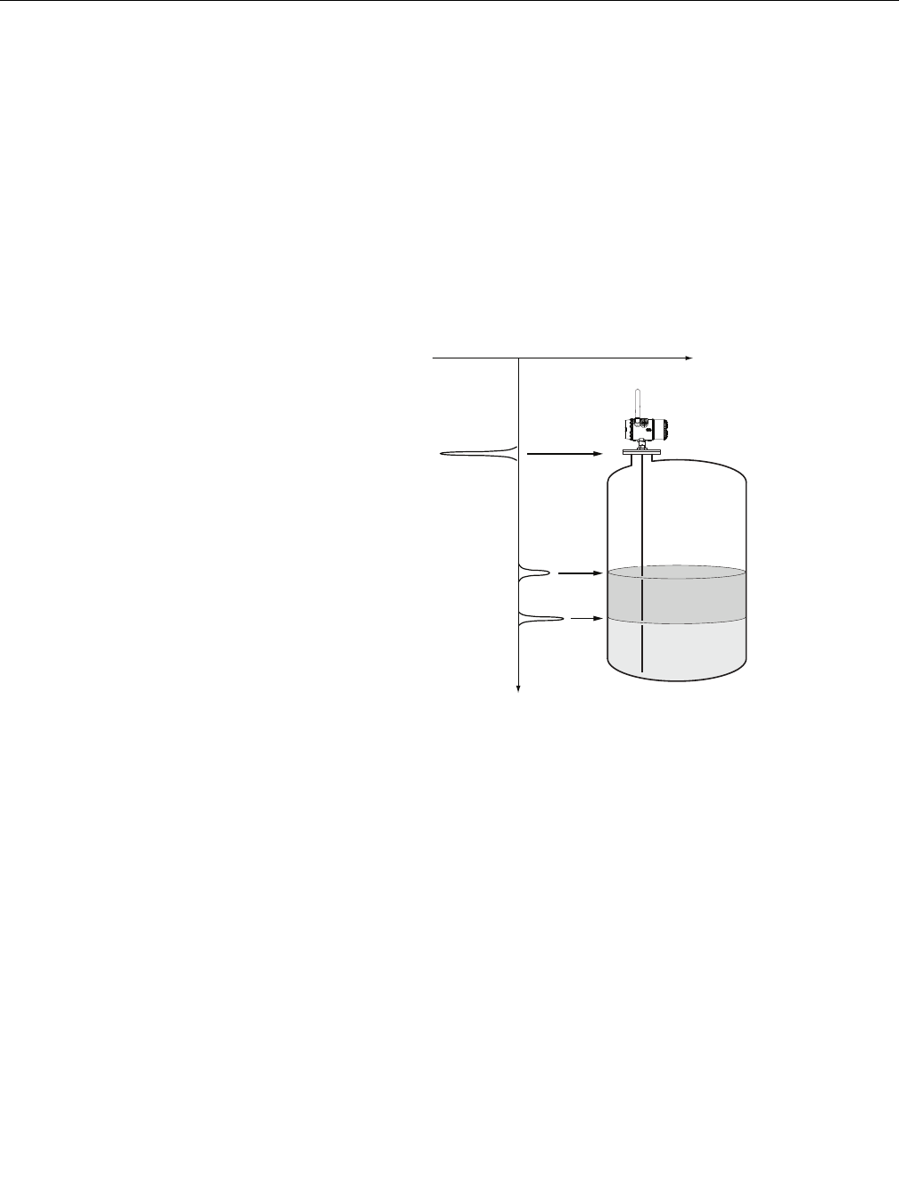
THEORY OF OPERATION The Rosemount 3308 Wireless Guided Wave Radar Level Transmitter is a
continuous level transmitter that is based on Time Domain Reflectometry
(TDR) principles. Low power nano-second-pulses are guided along a probe
immersed in the process media. When a pulse reaches the surface of the
material it is measuring, part of the energy is reflected back to the transmitter,
and the time difference between the generated and reflected pulse is
converted into a distance from which the total level or interface level is
calculated (see below).
The reflectivity of the product is a key parameter for measurement
performance. A high dielectric constant of the media gives better reflection
and a longer measuring range. A calm surface gives better reflection than a
turbulent surface.
Figure 2-1. Measurement
Principle.
APPLICATION
EXAMPLES The Rosemount 3308 transmitter is suited for aggregate (total) level
measurements on most liquids, semi-liquids, and liquid/liquid interfaces.
Guided microwave technology offers highest reliability and precision which
ensure measurements are virtually unaffected by temperature, pressure,
vapor gas mixtures, density, turbulence, bubbling/boiling, low level, varying
dielectric media, pH, and viscosity.
Guided wave radar technology in combination with advanced signal
processing make the Rosemount 3308 transmitter suitable for a wide range of
applications.
Time
Reference Pulse
Level
Interface Level
Signal Amplitude
Reference Manual
00809-XXXX-4811, Rev AA
February 2012
Rosemount 3308
2-4
PRELIMINARY
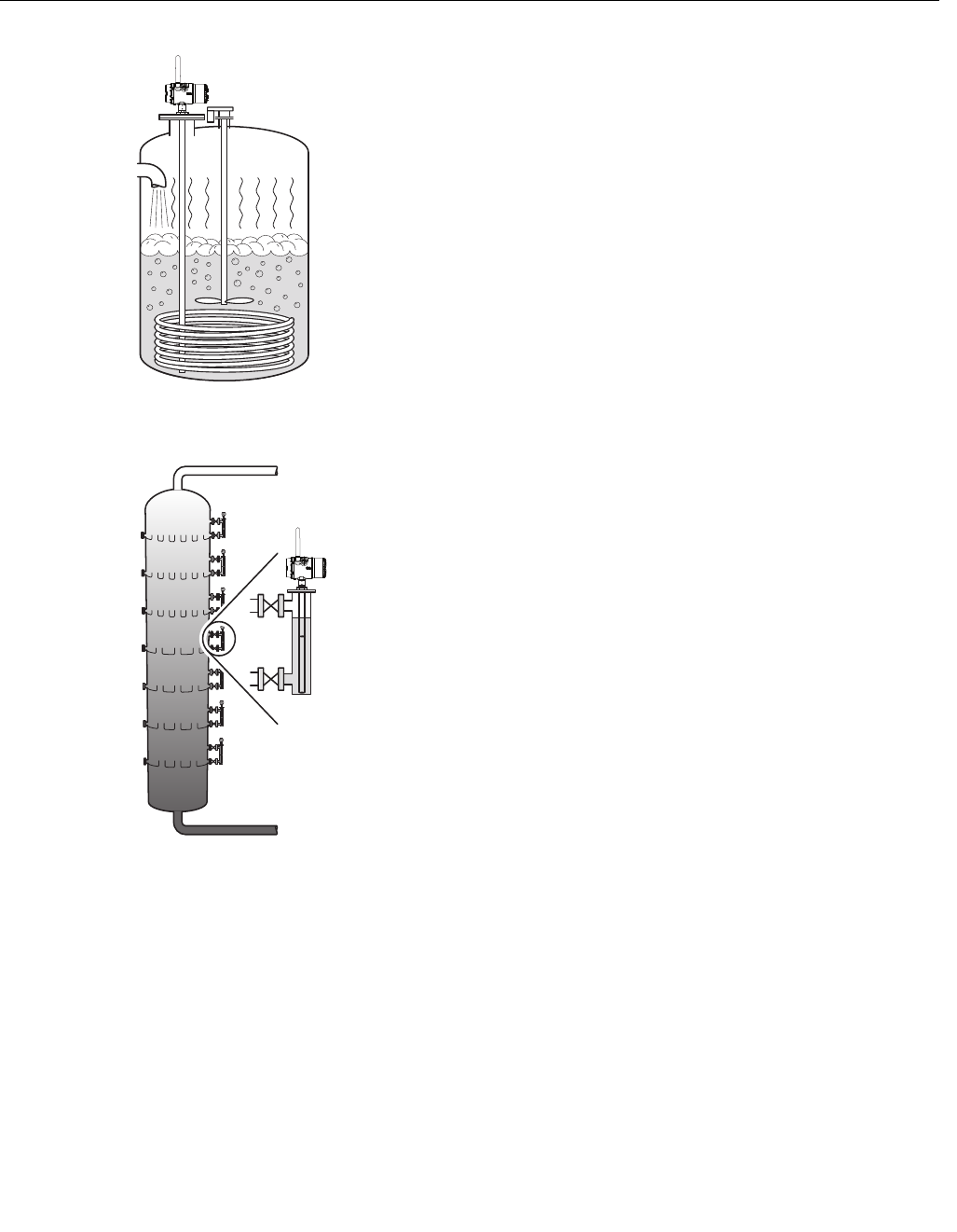
Boiling conditions with vapor and turbulence
For these applications the Coaxial probe is particularly
suitable.
Bridle applications
The Rosemount 3308 transmitter is well suited for bridle
applications, such as distillation columns.
Reference Manual
00809-XXXX-4811, Rev AA
February 2012
2-5
Rosemount 3308
PRELIMINARY
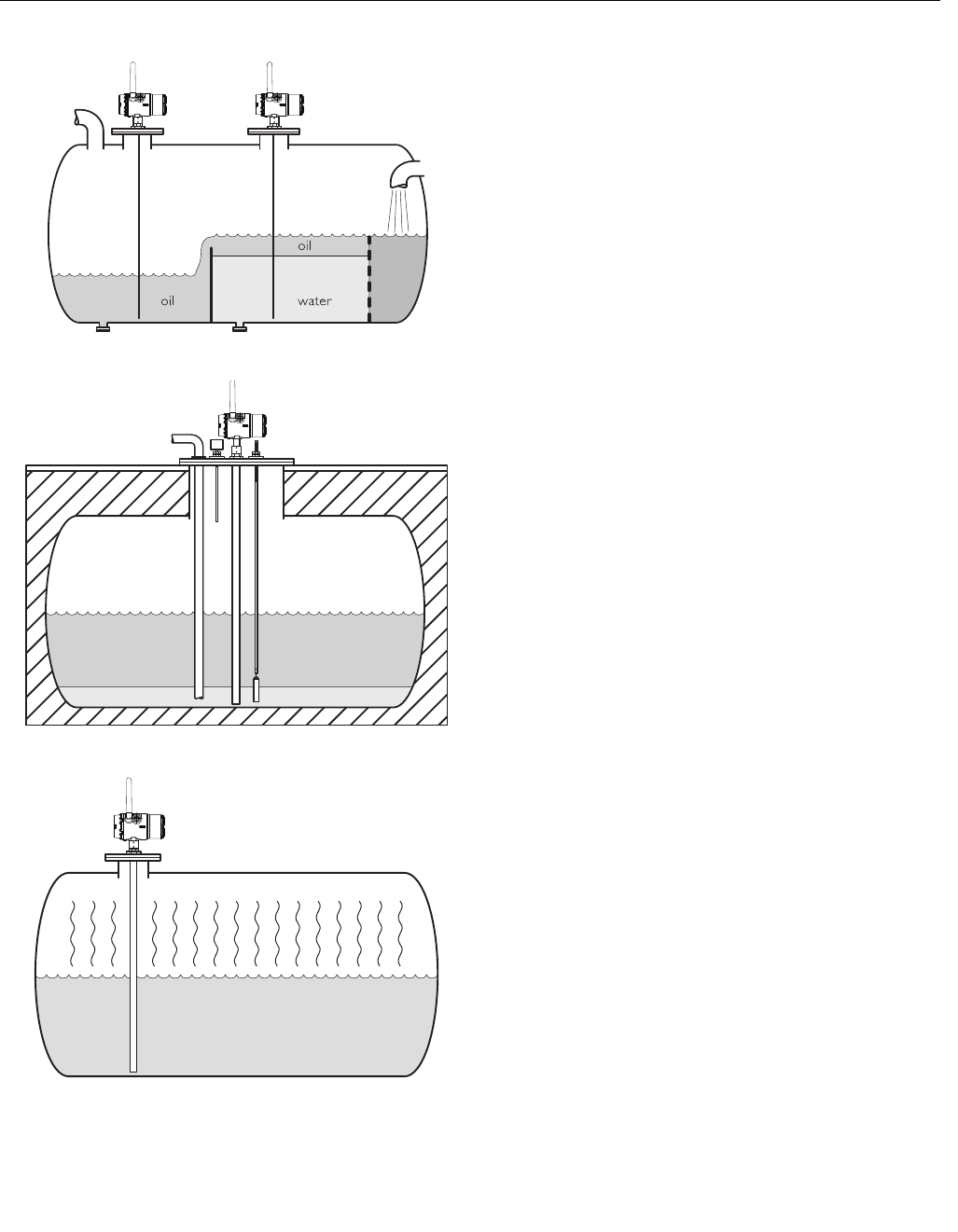
Separator tanks
The Rosemount 3308 measures both level and interface
level.
Underground tanks
The Rosemount 3308 transmitter is a good choice for
underground tanks since it is installed on the tank top
with the radar pulse concentrated near the probe. It can
be equipped with probes that are unaffected by high and
narrow openings or nearby objects.
Small ammonia, NGL and LPG tanks
Guided wave radar technology is a good choice for
reliable measurements in small ammonia, NGL and LPG
tanks.
Reference Manual
00809-XXXX-4811, Rev AA
February 2012
Rosemount 3308
2-6
PRELIMINARY
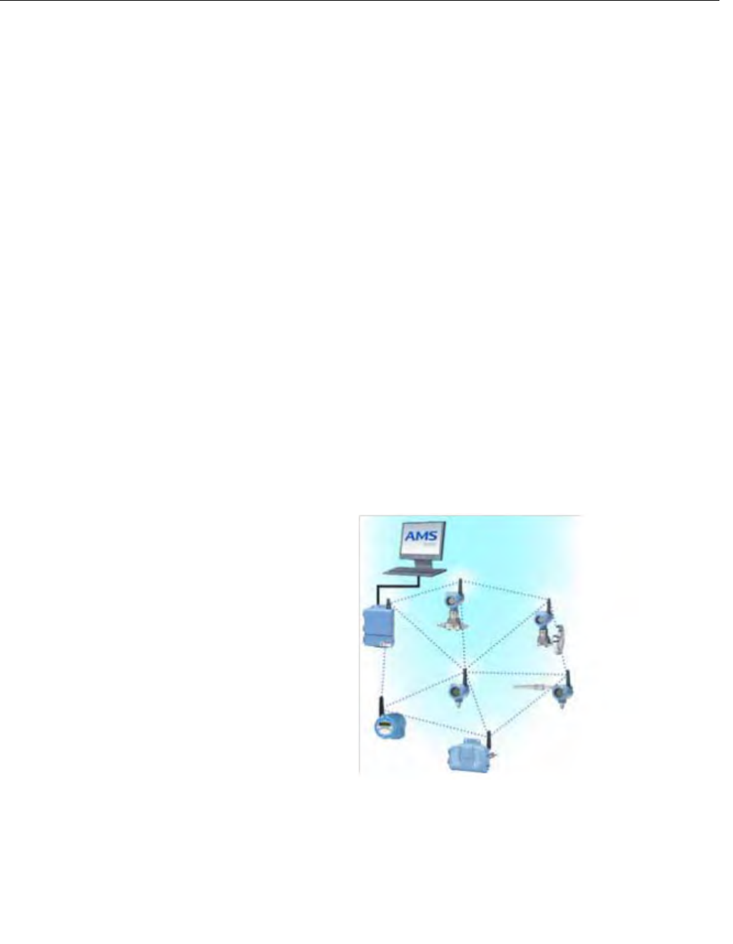
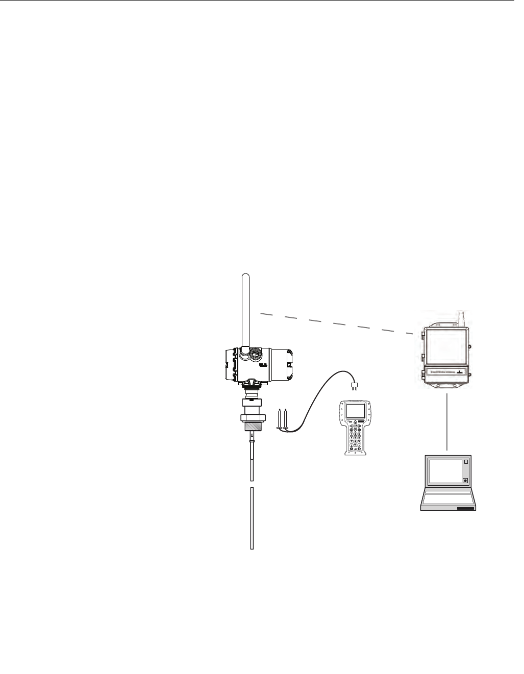
SYSTEM
ARCHITECTURE The Rosemount 3308 transmitter is battery powered with wireless
communication which means the unit works completely independent.
By using the optional HART Tri-loop, it is possible to convert the HART signal
to up to three additional 4-20 mA analog signals.
With the HART protocol it is possible to use multidrop configuration. In this
case communication is restricted to digital since current is fixed to the 4 mA
minimum value.
The transmitter can be connected to display Rosemount 751 Field Signal
Indicator or it can be equipped with an integral display.
The transmitter can easily be configured by using the AMS suite software or
by using a Field Communicator. A PC with the Radar Configuration Tool
software can also be used for configuration.
For HART communication a minimum load resistance of 250 within the loop
is required.
Figure 2-2. System architecture.
Field Communicator
Smart Wireless Gateway
Rosemount 3308 Wireless
Guided Wave Radar Transmitter
AMS Suite
Integral
Display
Reference Manual
00809-XXXX-4811, Rev AA
February 2012
2-7
Rosemount 3308
PRELIMINARY
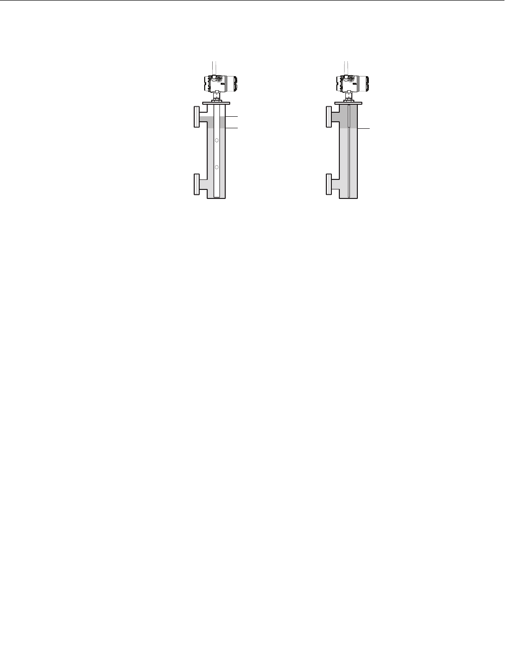
Interface Rosemount 3308 is the ideal choice for measuring the interface of oil and
water, or other liquids with significant dielectric differences.
Figure 2-3. Interface
measurement with a
Rosemount 3308
All probes can be used for measuring interfaces. The coaxial probe is the
preferred choice for clean liquids and when the bridle is not fully immersed. In
applications with a fully immersed probe, the twin lead probes are
recommended for nozzle installations, and the rigid single lead probe is best
for bridle mounting.
For measuring the interface level, the transmitter uses the residual wave of
the first reflection. Part of the wave, which was not reflected at the upper
product surface, continues until it is reflected at the lower product surface.
The speed of this wave depends fully on the dielectric constant of the upper
product.
If interface is to be measured, the following criteria have to be fulfilled:
• The dielectric constant of the upper product must be known. The Radar
Configuration Tools software has a built-in dielectric constant calculator
to assist users in determining the dielectric constant of the upper
product.
• The dielectric constant of the upper product must have a lower
dielectric constant than the lower product in order to have a distinct
reflection.
• The difference between the dielectric constants for the two products
must be larger than 10.
• Maximum dielectric constant for the upper product is 10 for the coaxial
probe and 5 for twin lead probes.
• The upper product thickness must be larger than 8 inches (0.2 m) for
the flexible twin lead probe and 4 inches (0.1 m) for the rigid twin lead
and coaxial probes in order to distinguish the echoes of the two liquids.
The maximum allowable upper product thickness/measuring range is
primarily determined by the dielectric constants of the two liquids.
Target applications include interfaces between oil/oil-like and water/water-like
liquids. For such applications the upper product dielectric constant is low (<3)
and the lower product dielectric constant is high (>20), and the maximum
measuring range is only limited by the length of the coaxial and rigid twin lead
probes.
Level
Interface Level Level = Interface Level

Reference Manual
00809-XXXX-4811, Rev AA
February 2012
Rosemount 3308
2-8
PRELIMINARY
Emulsion Layers
Sometimes there is an emulsion layer (mix of the products) between the two
products which, depending on its characteristics, will affect interface
measurements.
Please consult factory for guidelines on how to handle emulsion layers.

Reference Manual
00809-XXXX-4811, Rev AA
February 2012
2-9
Rosemount 3308
PRELIMINARY
VESSEL
CHARACTERISTICS
Heating Coils, Agitators The Rosemount 3308 transmitter is relatively insensitive to objects in the tank
since the radar signal is transmitted along a probe.
Avoid physical contact between probes and agitators as well as applications
with strong fluid movement unless the probe is anchored. If the probe can
move within 1 ft (30 cm) away from any object, such as an agitator, during
operation then probe tie-down is recommended.
In order to stabilize the probe for side forces, it is possible to hang a weight at
the probe end (flexible probes only) or fix/guide the probe to the tank bottom.
Tank Shape The guided wave radar transmitter is insensitive to the tank shape. Since the
radar signal travels along a probe, the shape of the tank bottom has virtually
no effect on the measurement performance. The transmitter handles flat or
dish-bottom tanks equally well.
Reference Manual
00809-XXXX-4811, Rev AA
February 2012
Rosemount 3308
2-10
PRELIMINARY
COMPONENTS OF THE
TRANSMITTER The Rosemount 3308 transmitter has an aluminum transmitter housing which
contains advanced electronics for signal processing.
The radar electronics produces an electromagnetic pulse which is guided by
the probe.
There are different probe types available for various applications: Flexible
Twin Lead, Rigid Single Lead, Flexible Single Lead, and Coaxial.
Figure 2-4. Transmitter
components.
Radar Electronics
Probe
Dual Compartment Housing
Threaded Process
Connections
Flanged Process
Connections
BSP (G)
NPT
Coaxial
Flexible Twin Lead with weight
Rigid Single Lead
Flexible Single Lead with weight

Reference Manual
00809-XXXX-4811, Rev AA
February 2012
2-11
Rosemount 3308
PRELIMINARY
PROBE SELECTION
GUIDE Use the following guidelines to choose appropriate probe for your
Rosemount 3308 transmitter:
Table 2-1. Probe selection guide. G=Good, NR=Not Recommended, AD=Application Dependent (consult factory)
Coaxial Rigid Twin Lead Flexible Twin Lead Rigid Single Lead Flexible Single Lead
Measurements
Level GGGGG
Interface (liquid/liquid) G(1) G G NR NR
Process Medium Characteristics
Changing density G GGGG
Changing dielectric(2) GGGGG
Wide pH variationsGGGGG
Pressure changes G GGGG
Temperature changes G GGGG
Condensing vapors G GGGG
Bubbling/boiling surfaces G G AD G AD
Foam (mechanical
avoidance) AD NR NR NR NR
Foam (top of foam
measurement) NR AD AD AD AD
Foam (foam and liquid
measurement) NR AD AD NR NR
Clean liquids GGGGG
Liquid with dielectric<2.5 G AD AD AD(3) NR
Coating liquids NR NR NR AD AD
Viscous liquids NR AD AD AD G
Crystallizing liquids NR NR NR AD AD
Solids/Powders NR NR NR AD AD
Fibrous liquids NR NR NR G G
Tank Environment Considerations
Probe is close
(<12 in./30 cm) to tank wall
/ disturbing objects
GADADNRNR
High turbulence G G AD G AD
Turbulent conditions
causing breaking forces NR NR AD NR AD
Long and small mounting
nozzles
(diameter <6 in./15 cm,
height>diameter + 4 in./10
cm)
G ADNRNRNR
Probe might touch nozzle /
disturbing object G NRNRNRNR
Liquid or vapor spray might
touch probe G NRNRNRNR
Disturbing EMC
environment in tank AD NR NR NR NR
(1) Not in fully immersed applications.
(2) For overall level applications a changing dielectric has no effect on the measurement. For interface measurements a changing dielectric of the top fluid
will degrade the accuracy of the interface measurement.
(3) OK when installed in pipe.
Reference Manual
00809-XXXX-4811, Rev AA
February 2012
Rosemount 3308
2-12
PRELIMINARY
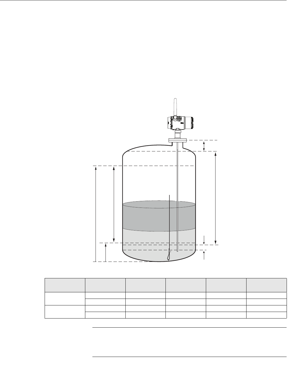
Transition Zones The measuring range depends on probe type and properties of the product.
The Upper Transition Zone is the minimum measurement distance between
the upper reference point and the product surface. The Upper Transition Zone
varies between 4 - 20 in. (0.1 and 0.5 m) depending on probe type and
product.
At the end of the probe the measuring range is reduced by the Lower
Transition Zone. The Lower Transition Zone also varies depending on
probe type and product.
Figure 2-5 illustrates how the measuring range is related to the Transition
Zones:
Figure 2-5. Transition Zones
NOTE
The measurement accuracy is reduced in the Transition Zones. It may even
be impossible to make any measurements at all in those regions. Therefore,
the alarm limit points should be configured outside the Transition Zones.
4mA
20mA
Upper Transition Zone
Lower Transition Zone
Range 0 -100 %
Maximum Measuring
Range
Upper Reference Point
Table 2-2. Transition Zones for different probe types
Dielectric
Constant Coaxial Probe Flexible Twin
Lead Probe Rigid Single
Lead Probe Flexible Single
Lead Probe
Upper
Transition Zone
2TO BE ADDED
80
Lower
Transition Zone
2
80
Reference Manual
00809-XXXX-4811, Rev AA
February 2012
2-13
Rosemount 3308
PRELIMINARY
SERVICE SUPPORT To expedite the return process outside of North America, contact your
Emerson Process Management representative,
Within the United States, call the Emerson Process Management Response
Center toll-free number 1 800 654 7768. The center, which is available 24
hours a day, will assist you with any needed information or materials.
The center will ask for product model and serial numbers, and will provide a
Return Material Authorization (RMA) number. The center will also ask for the
process material to which the product was last exposed.
SHIPPING CONSIDERATIONS FOR WIRELESS PRODUCTS (LITHIUM
BATTERIES)
The unit was shipped with the Power Module not installed. Please remove the
Power Module from the unit before shipping.
Each Power Module contains two "C" size primary lithium/thionyl chloride
batteries. Primary lithium batteries (charged or discharged) are regulated
during transportation by the U.S. Department of Transportation. They are also
covered by IATA (International Air Transport Association), ICAO (International
Civil Aviation Organization), and ARD (European Ground Transportation of
Dangerous Goods). It is the responsibility of the shipper to ensure compliance
with these or any other local requirements. Consult current regulations and
requirements before shipping.
PRODUCT
RECYCLING/DISPOSAL Recycling of equipment and packaging should be taken into consideration
and disposed of in accordance with local and national legislation/regulations.
Individuals who handle products exposed to a hazardous substance can avoid injury if they
are informed of, and understand, the hazard. If the product being returned was exposed to a
hazardous substance as defined by OSHA, a copy of the required Material Safety Data
Sheet (MSDS) for each hazardous substance identified must be included with the returned
goods.

Reference Manual
00809-XXXX-4811, Rev AA
February 2012
Rosemount 3308
2-14
PRELIMINARY

Reference Manual
00809-XXXX-4811, Rev AA
February 2012 Rosemount 3308
www.rosemount.com
PRELIMINARY
Section 3 Wireless Configuration
Safety Messages . . . . . . . . . . . . . . . . . . . . . . . . . . . . . . . . . page 3-1
Wireless Considerations . . . . . . . . . . . . . . . . . . . . . . . . . . page 3-2
Power Module Installation . . . . . . . . . . . . . . . . . . . . . . . . . page 3-5
Device Configuration . . . . . . . . . . . . . . . . . . . . . . . . . . . . . page 3-6
Device Network Configuration . . . . . . . . . . . . . . . . . . . . . page 3-6
Remove Power Module . . . . . . . . . . . . . . . . . . . . . . . . . . . page 3-7
SAFETY MESSAGES Instructions and procedures in this section may require special precautions to
ensure the safety of the personnel performing the operations. Information that
potentially raises safety issues is indicated by a warning symbol ( ). Please
refer to the following safety messages before performing an operation
preceded by this symbol.
Warnings
Probe Connection; warnings associated with probe connections
Failure to follow these installation guidelines could result in death or serious
injury:
• Only qualified personnel should perform the installation
Explosions could result in death or serious injury:
Installation of this transmitter in an explosive environment must be in accordance with
the appropriate local, national, and international standards, codes, and practices.
Please review the Product Certifications section for any restrictions associated with a
safe installation.
• Before connecting a Field Communicator in an explosive atmosphere, make
sure that the instruments are installed in accordance with intrinsically safe or
non-incendive field wiring practices
Process leaks may cause harm or result in death:
• Do not remove the transmitter while in operation
• Install the transmitter prior to process start-up
Electrical shock could cause death or serious injury:
• Avoid contact with the leads and terminals. High voltage that may be present
on leads can cause electrical shock
This device complies with Part 15 of the FCC Rules. Operation is subject to the
following conditions: This device may not cause harmful interference. This device must
accept any interference received, including interference that may cause undesired
operation. This device must be installed to ensure a minimum antenna separation
distance of 20 cm (8 in.) from all persons.
Reference Manual
00809-XXXX-4811, Rev AA
February 2012
Rosemount 3308
3-2
PRELIMINARY
WIRELESS
CONSIDERATIONS
General The Wireless Guided Wave Radar Transmitter has the capability to measure
level, distance, interface level or volume. The Rosemount 3308 converts the
measurement data into mapped variables and diagnostic information that are
transmitted through a wireless signal.
Power Up Sequence
The Smart Wireless Gateway (Gateway) should be installed and functioning
properly before any wireless field devices are powered. Install the Black
Power Module, SmartPower™ Solutions model number 701PBKKF into the
3308 transmitter to power the device. Wireless devices should also be
powered up in order of proximity from the Gateway, beginning with the
closest. This will result in a simpler and faster network installation. Enable
Active Advertising on the Gateway to ensure that new devices join the
network faster. For more information, see the Gateway Product Manual
(Document Number 00809-0200-4420).
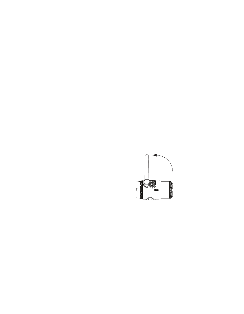
Antenna Position
The antenna should be positioned vertically, either straight up or straight
down. It should be approximately 3 ft (1 m) from any large structure, building,
or conductive surface to allow for clear communication to other devices.
Figure 3-1. Recommended
Antenna Position
Conduit Entries
Unit comes with both conduit entries sealed with conduit plugs using an
approved thread sealant.
Reference Manual
00809-XXXX-4811, Rev AA
February 2012
3-3
Rosemount 3308
PRELIMINARY
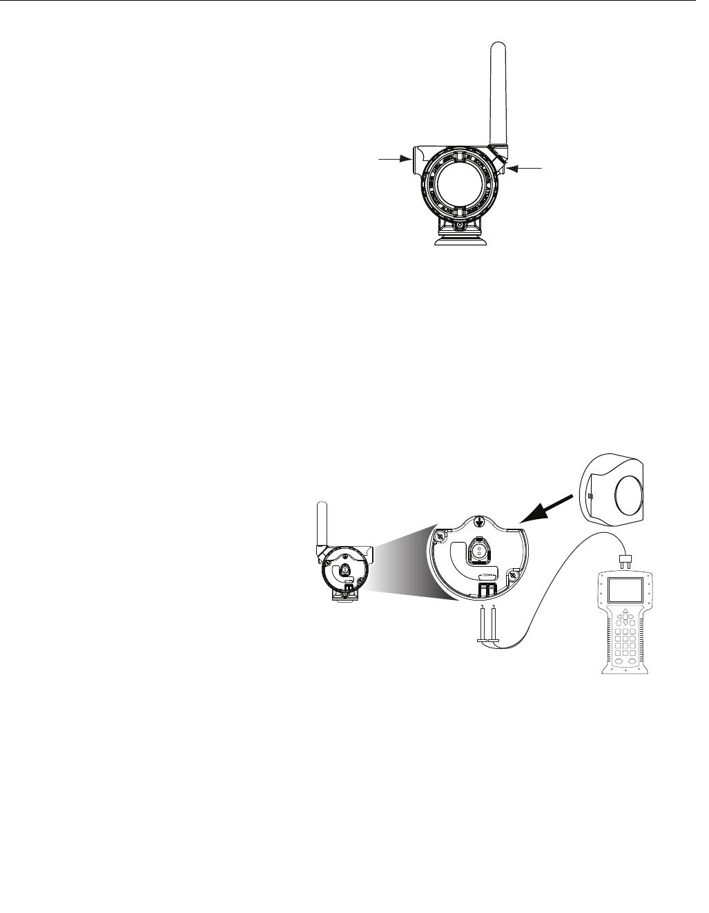
Figure 3-2. Conduit Entries
Field Communicator Connections
The Power Module needs to be installed in the device for the Field
Communicator to interface with the Rosemount 3308 transmitter. This
transmitter uses the Black Power Module; please order model number
701PBKKF. Field communication with this device requires a HART-based
Field Communicator using the correct Rosemount 3308 Wireless DD. Field
communicator connections are located on the terminal block. The correct DD
for the available protocol should be selected. Refer to Figure 3-3 for
instructions on connecting the Field Communicator to the Rosemount 3308.
Figure 3-3. Field Communicator
Connection Diagram
Mechanical Location
When choosing an installation location and position, take into account access
to the transmitter for easy Power Module replacement. For best performance,
the antenna should be vertical with space between objects in a parallel metal
plane, such as a pipe or metal framework, as the pipes or framework may
adversely affect the antenna's performance.
Conduit Entry Conduit Entry
P/N 00753-9200-2410
P/N 00753-9200-2410

Reference Manual
00809-XXXX-4811, Rev AA
February 2012
Rosemount 3308
3-4
PRELIMINARY
Electrical The Rosemount 3308 Wireless Guided Wave Radar transmitter is
self-powered. The Black Power Module contains two "C" size primary
lithium/thionyl chloride batteries. Each battery contains approximately 2.5
grams of lithium, for a total of 5 grams in each Power Module. Under normal
conditions, the battery materials are self-contained and are not reactive as
long as the batteries and the Power Module are maintained. Care should be
taken to prevent thermal, electrical, or mechanical damage. Contacts should
be protected to prevent premature discharge.
Use caution when handling the power module; it may be damaged if dropped
from heights in excess of 20 ft (6.10 m).
Reference Manual
00809-XXXX-4811, Rev AA
February 2012
3-5
Rosemount 3308
PRELIMINARY
POWER MODULE
INSTALLATION NOTE
Wireless devices should be powered up in order of proximity from the Smart
Wireless Gateway, beginning with the closest device to the Smart Wireless
Gateway. This will result in a simpler and faster network installation.
1. Install the Power Module.
Figure 3-4. Black Power Module
Installation
NOTE
Use caution when handling the power module, it may be damaged if dropped
from heights in excess of 20 ft (6 m).
2. Close the housing cover and tighten to site or safety specifications.
Always ensure a proper seal by installing the electronics housing covers
so that metal touches metal, but do not over tighten.
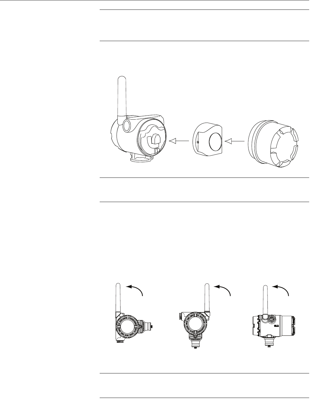
3. Position the antenna such that it is vertical, either straight up or straight
down, as shown in Figure 3-5. The antenna should be approximately 3 ft
(1 m) from any large structures or buildings to allow clear communication
to other devices.
Figure 3-5. Possible Antenna
Rotations
NOTE
Possible antenna rotation shown. Antenna rotation allows for best installation
practices in any configuration.
TO BE UPDATED
Reference Manual
00809-XXXX-4811, Rev AA
February 2012
Rosemount 3308
3-6
PRELIMINARY
DEVICE
CONFIGURATION Remove the Power Module-side housing cover to expose the terminal block
and HART communication terminals, then connect the Power Module to
power the unit for configuration.
The Rosemount 3308 transmitter will receive any HART communication from
a handheld Field Communicator or AMS Wireless Configurator. When using a
Field Communicator, any configuration changes must be sent to the
transmitter using the Send key (F2). AMS Wireless Configurator configuration
changes are implemented when the Apply button is clicked.
AMS® Wireless Configurator
AMS Wireless Configurator is capable of connecting to devices directly, using
a HART modem, or remotely using the Gateway.
When configuring on the bench with a HART modem, double click the device
icon, then choose the Configure/Setup tab (or right click and select
Configure/Setup). Configure the device settings using the Direct Connection
menu.
When configuring with the Gateway, double click the device icon then choose
the Configure/Setup tab (or right click and select Configure/Setup). Configure
the device settings using the Wireless Connection menu.
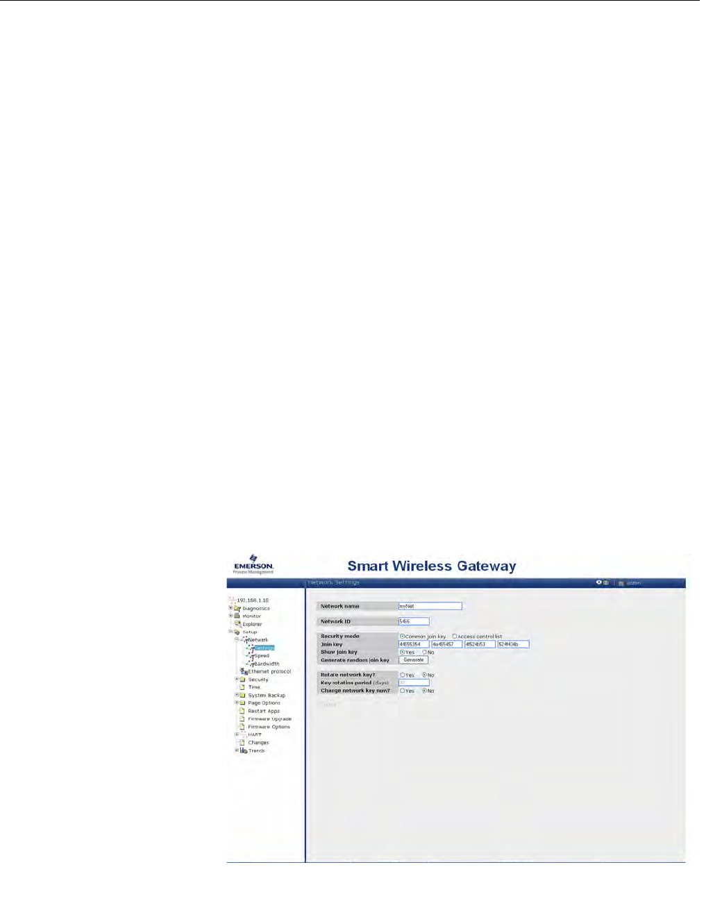
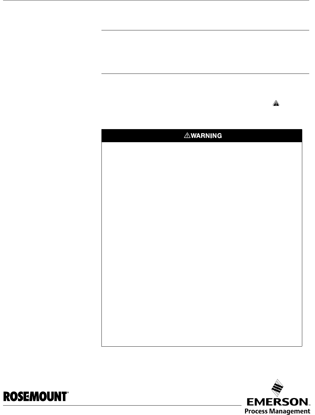
DEVICE NETWORK
CONFIGURATION To communicate with the Gateway, and ultimately the host system, the
transmitter must be configured to communicate with the wireless network.
Using a Field Communicator or AMS Wireless Configurator, enter the
Network ID and Join Key so they match the Network ID and Join Key of the
Gateway and the other devices in the network. If the Network ID and Join Key
are the same as the Gateway, the transmitter will not communicate with the
network. The Network ID and Join Key may be obtained from the Gateway on
the Setup>Network>Settings page on the Gateway's integrated web server,
shown in Figure 3-6.
Figure 3-6. Gateway Network
Settings
Reference Manual
00809-XXXX-4811, Rev AA
February 2012
3-7
Rosemount 3308
PRELIMINARY
AMS Right click on the Rosemount 3308 transmitter and select Configure. When
the menu opens, select Join Device to Network and complete the method to
enter the Network ID and Join Key.
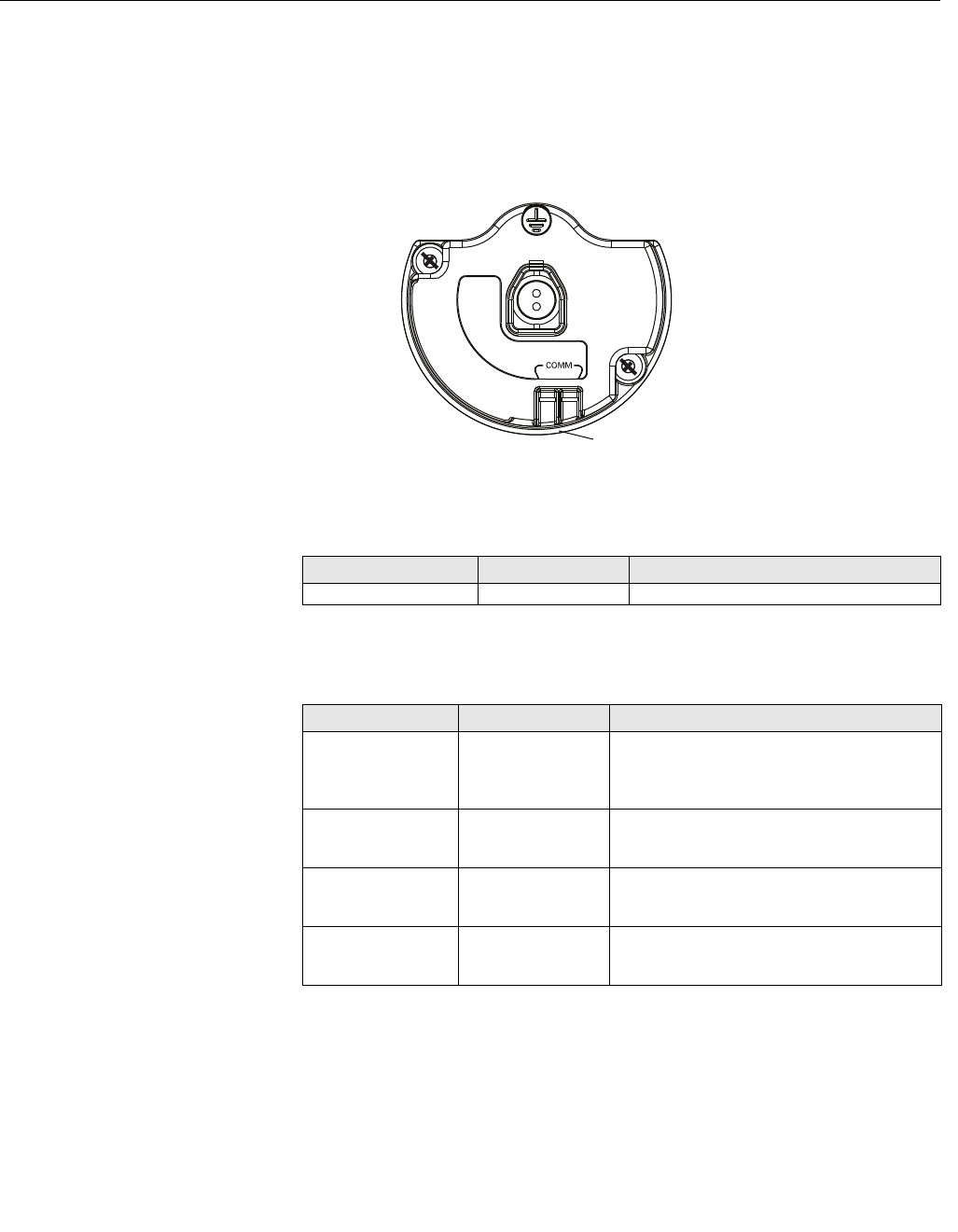
Field Communicator Connect the field communicator leads to the COMM terminals on the terminal
block as shown in Figure 3-7.
Figure 3-7. Terminal Block with
COMM terminals
The Network ID and Join Key may be changed in the wireless device on a
Field Communicator by using the Fast Key Sequence shown in Table 3-1.
Table 3-1. Rosemount 3308
Fast Key Sequence
Fast Key Sequences Table 3-1 lists the fast key sequence for common transmitter functions.
Table 3-2. Rosemount 3308
Fast Key Sequence
REMOVE POWER
MODULE If doing a bench top configuration, after the sensor and network have been
configured, remove the Power Module and replace the transmitter cover. The
Power Module should be inserted only when the device is ready for
commissioning.
P/N 00753-9200-2410
COMM terminals
Function Key Sequence Menu Items
Join Device to Network 2, 1, 2 Network ID, Set Join Key
Function Key Sequence Menu Items
Device Information 2, 2, 4 Manufacturer, Model, Final Assembly Number,
Universal, Field Device, Software, Hardware
Descriptor, Message, Date, Model Number, I, II,
III, SI Unit Restriction, Country
Guided Setup 2, 1 Join Device to Network, Configure Update Rate,
Configure Sensor, Calibrate Sensor, Configure
Display, Configure Process Alarms
Manual Setup 2, 2 Wireless, Process Sensor, Percent of Range,
Device Temperature, Device Information,
Device Configure, Other
Wireless 2, 2, 1 Network ID, Join Device to Network, Configure
Update Rate, Configure Broadcast Power Level,
Power Mode, Power Source

Reference Manual
00809-XXXX-4811, Rev AA
February 2012
Rosemount 3308
3-8
PRELIMINARY
Reference Manual
00809-XXXX-4811, Rev AA
February 2012 Rosemount 3308
www.rosemount.com
PRELIMINARY
Section 4 Installation
Safety messages . . . . . . . . . . . . . . . . . . . . . . . . . . . . . . . . . page 4-1
Installation Procedure . . . . . . . . . . . . . . . . . . . . . . . . . . . . page 4-3
Before You Install . . . . . . . . . . . . . . . . . . . . . . . . . . . . . . . . page 4-4
Mounting Considerations . . . . . . . . . . . . . . . . . . . . . . . . . page 4-5
Mechanical Installation . . . . . . . . . . . . . . . . . . . . . . . . . . . page 4-11
SAFETY MESSAGES Procedures and instructions in this section may require special precautions to
ensure the safety of the personnel performing the operations. Information that
raises potential safety issues is indicated by a warning symbol ( ). Please
refer to the following safety messages before performing an operation
preceded by this symbol.
Failure to follow safe installation and servicing guidelines could result in death or
serious injury:
Make sure only qualified personnel perform the installation.
Use the equipment only as specified in this manual. Failure to do so may impair the
protection provided by the equipment.
Do not perform any service other than those contained in this manual unless you are
qualified.
Explosions could result in death or serious injury:
Installation of this transmitter in an explosive environment must be in accordance with the
appropriate local, national, and international standards, codes, and practices. Please review
the Product Certifications section for any restrictions associated with a safe installation.
Verify that the operating environment of the transmitter is consistent with the appropriate
hazardous locations certifications.
Before connecting a HART-based communicator in an explosive atmosphere, make sure
the instruments in the loop are installed in accordance with intrinsically safe or
non-incendive field wiring practices.
In an Explosion-proof/Flameproof installation, do not remove the transmitter cover when
power is applied to the unit.
Process leaks could result in death or serious injury:
Make sure that the transmitter is handled carefully. If the Process Seal is damaged, gas
might escape from the tank if the transmitter head is removed from the probe.
• Do not remove the transmitter while in operation
• Install device prior to process start-up

Reference Manual
00809-XXXX-4811, Rev AA
February 2012
Rosemount 3308
4-2
PRELIMINARY
Electrical shock can result in death or serious injury:
• Avoid contact with the leads and terminals. High voltage that may be present on
leads can cause electrical shock.
Probes covered with plastic and/or with plastic discs may generate an ignition-capable level
of electrostatic charge under certain extreme conditions. Therefore, when the probe is used
in a potentially explosive atmosphere, appropriate measures must be taken to prevent
electrostatic discharge.
This device complies with Part 15 of the FCC Rules. Operation is subject to the following
conditions: This device may not cause harmful interference. This device must accept any
interference received, including interference that may cause undesired operation. This
device must be installed to ensure a minimum antenna separation distance of 20 cm (8 in.)
from all persons.
Reference Manual
00809-XXXX-4811, Rev AA
February 2012
4-3
Rosemount 3308
PRELIMINARY
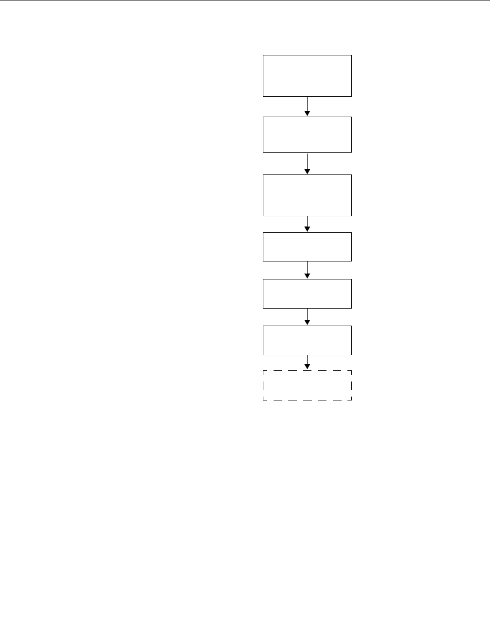
INSTALLATION
PROCEDURE Follow these steps for proper installation:
Review Installation
Considerations
(see page 4-5)
Mount the transmitter
(see page 4-11)
Make sure covers
and cable/conduit
connections are
tight.
Power Up the
transmitter
Configure the
transmitter
(see page 5-1)
Verify measurements
Set the Write
Protection Switch

Reference Manual
00809-XXXX-4811, Rev AA
February 2012
Rosemount 3308
4-4
PRELIMINARY
BEFORE YOU INSTALL Electronic boards are electrostatically sensitive. Failure to observe proper
handling precautions for static-sensitive components can result in damage to
the electronic components. Do not remove the electronic boards from the
Rosemount 3308 transmitter.
NOTE
To ensure long life for your radar transmitter, and to comply with hazardous
location installation requirements, tighten covers on both sides of the
electronics housing.
Software write protect Security write protection prevents unauthorized access to configuration data
through a Field Communicator or AMS Suite software.
Reference Manual
00809-XXXX-4811, Rev AA
February 2012
4-5
Rosemount 3308
PRELIMINARY
MOUNTING
CONSIDERATIONS Before installing the Rosemount 3308 transmitter, consider specific mounting
requirements, vessel characteristics and process characteristics.
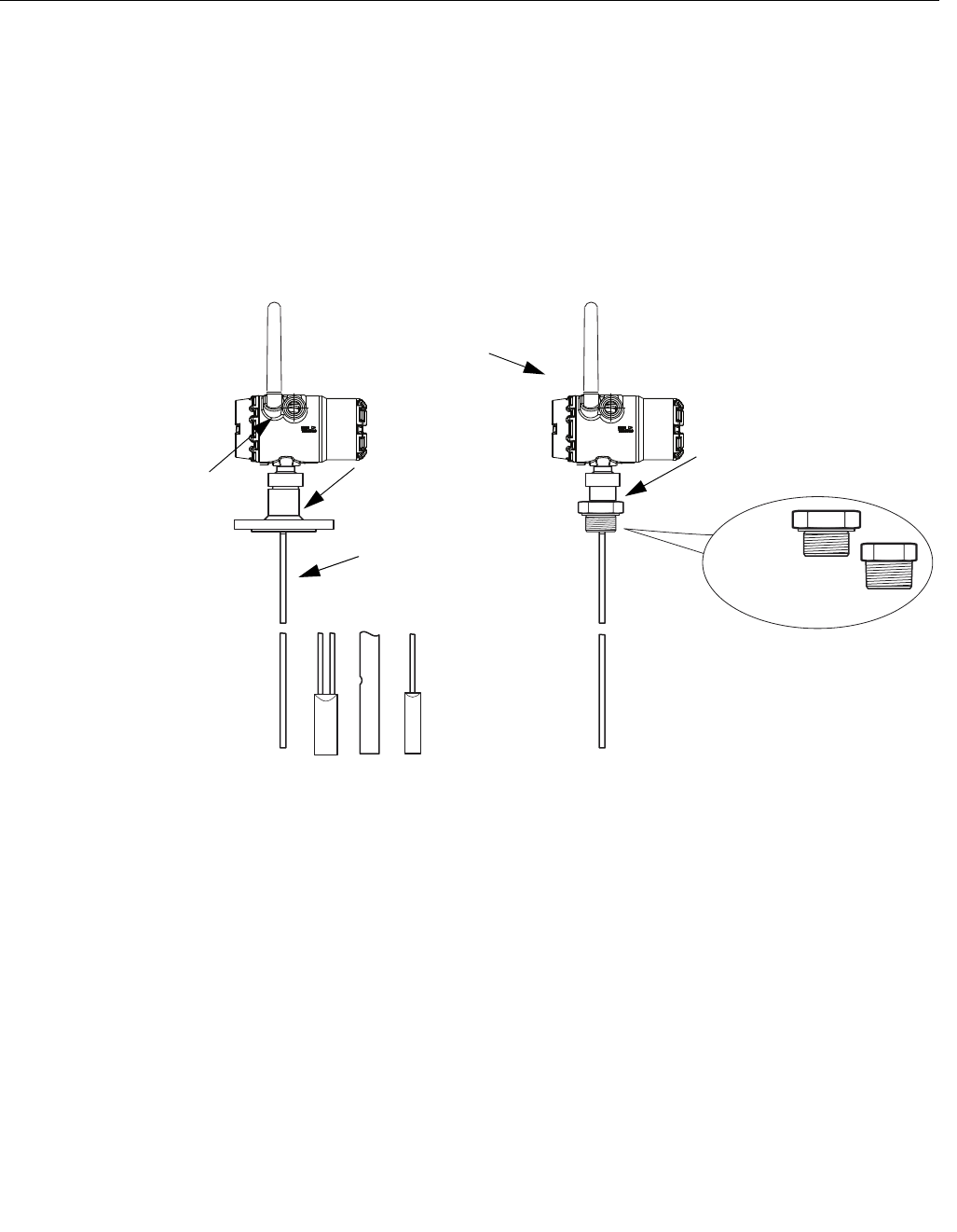
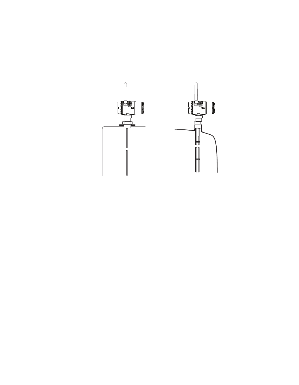
Process Connection The Rosemount 3308 transmitter has a threaded connection for easy
mounting on the tank roof. It can also be mounted on a nozzle by using
different flanges.
Threaded Connection
Figure 4-1. Mounting on tank
roof using threaded connection
Mounting on tank roof Mounting in threaded pipe
Reference Manual
00809-XXXX-4811, Rev AA
February 2012
Rosemount 3308
4-6
PRELIMINARY
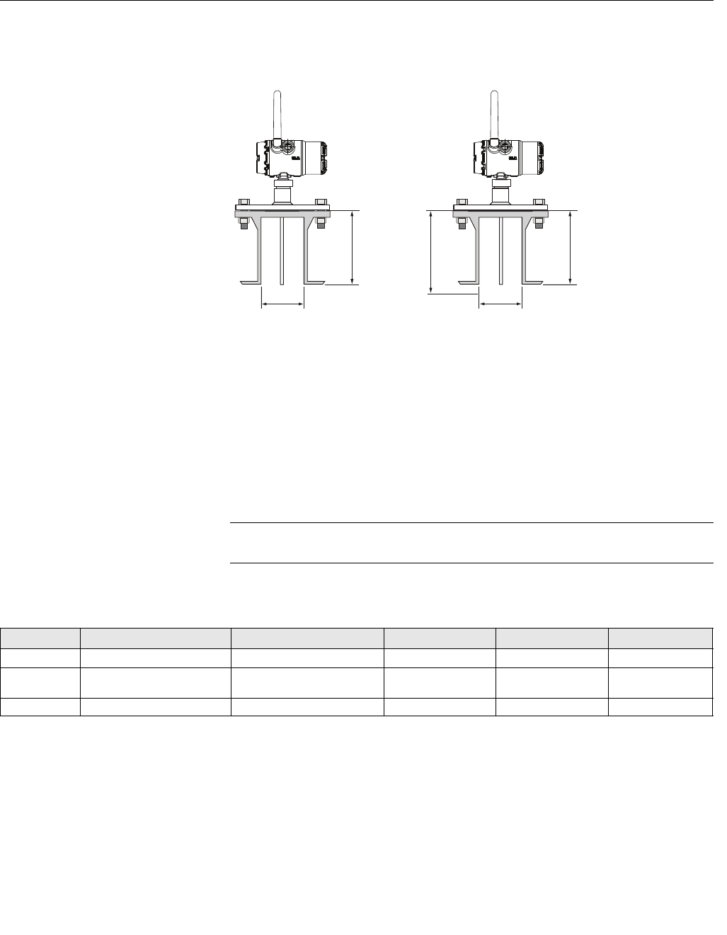
Flange Connection on Nozzles
Figure 4-2. Mounting in nozzles
The transmitter can be mounted in nozzles by using an appropriate flange. It
is recommended that the nozzle size is within the dimensions given in
Table 4-1. For small nozzles it may be necessary to increase the Upper Null
Zone (UNZ) in order to reduce the measuring range in the upper part of the
tank. By setting the UNZ equal to the nozzle height, the impact on the
measurement due to interfering echoes from the nozzle will be reduced to a
minimum. See also section “Disturbances at the Top of the Tank“ on
page 7-10. Amplitude Threshold adjustments may also be needed in this
case.
NOTE
Except for the Coaxial Probe the probe must not be in contact with the nozzle.
Table 4-1. Minimum nozzle diameter D1/D2 and maximum nozzle height H (inch/mm).
H
D2 = min. diameter with Upper Null
Zone adjustment
H
UNZ
D1 = min. diameter
Rigid Twin Lead Flexible Twin Lead Coaxial Single Lead Flexible Single
D1(1) 4/100 4/100 > Probe diameter 6/150 6/150
D2(2) 2/50 2/50 > Probe diameter 2/50(3)
1.5/38(4) 2/50
H(5) 4/100 + D(6) 4/100 + D(6) - 4/100 + D(6) 4/100 + D(6) (7)
(1) Upper Null Zone=0.
(2) Upper Null Zone>0.
(3) Process connection 1.5 inch.
(4) Process connection 1 inch.
(5) Recommended maximum nozzle height. For coaxial probes there is no limitation on nozzle height.
(6) Nozzle diameter.
(7) For tall nozzles the Long Stud version is recommended (option code LS).
Reference Manual
00809-XXXX-4811, Rev AA
February 2012
4-7
Rosemount 3308
PRELIMINARY
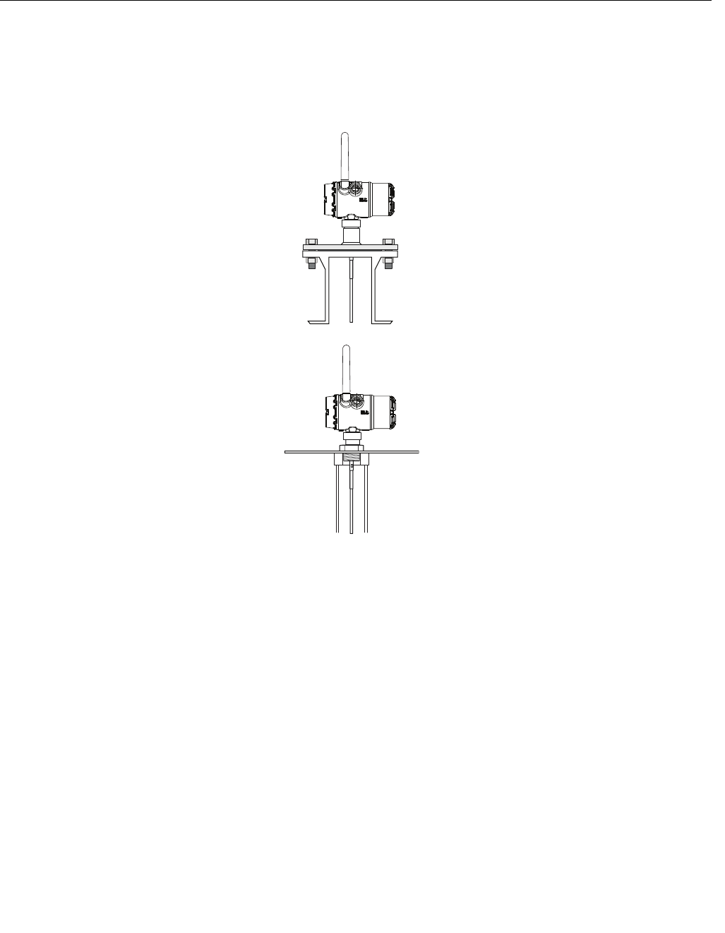
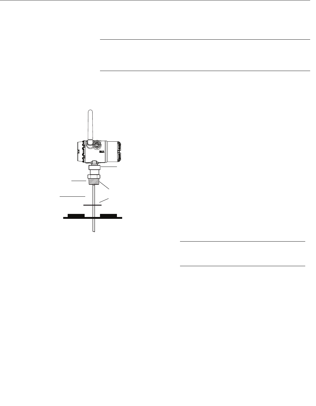
Installation of Single
Lead Probes in
Non-metallic Tanks
For optimal single lead probe performance in non-metallic tanks the probe
must be mounted with a metal flange, or screwed in to a metal sheet
(d>8 in./200 mm) if the threaded version is used.
Figure 4-3. Mounting in
non-metallic tanks.
Avoid introducing EMI environment near the tank. Installation in metallic tank
is recommended.
Metal flange Ø > 2 in. (DN50)
Metal sheet Ø > 8 in. (200 mm)
Reference Manual
00809-XXXX-4811, Rev AA
February 2012
Rosemount 3308
4-8
PRELIMINARY
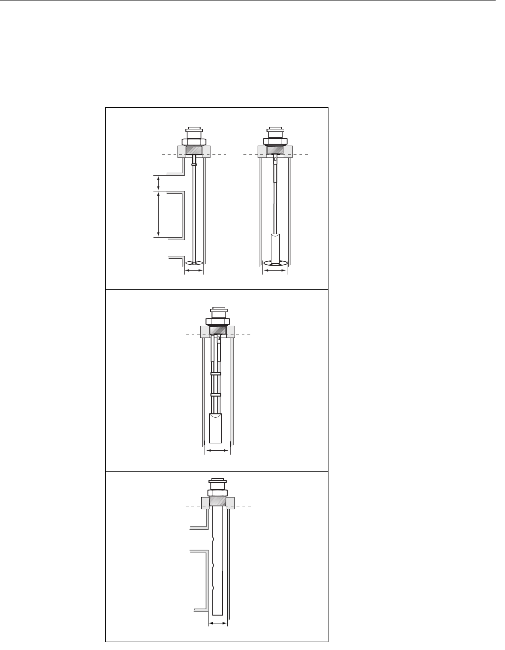
Mounting in Still
pipes/by-pass pipes In order to prevent the probe from contacting the bridle wall when replacing
displacers or installing in pipes, centering discs are available for the Rigid
Single, Flexible Single and Flexible Twin Lead probes. The disc is attached to
the end of the probe and thus keeps the probe centered in the bridle. The
discs are available in stainless steel and PTFE. See also “Mounting a
Centering Disc for Pipe Installations“ on page 4-17.
Figure 4-4. Mounting in
Still Pipes. Note! It is not recommended that flexible
probes are installed in by-pass pipes.
Rigid Single Lead.
Pipe diameter Ø2 in. (50 mm).
Inlet pipe diameter N<Ø.
L12 in. (300 mm).
Flexible Single Lead.
Pipe diameter Ø4 in. (100 mm).
Note! For smaller pipes please consult
factory.
Make sure that the probe is at the center of
the Still pipe by, for example, using a
centering disc.
Note! It is not recommended that flexible
probes are installed in by-pass pipes.
Flexible Twin Lead.
Pipe diameter Ø4 in. (100 mm).
Note! For smaller pipes please consult
factory.
The center rod must be placed more than
0.6 in. (15 mm) away from the pipe wall. The
probe may under no circumstances get into
contact with the pipe wall. It is recommended
that a centering disc is used.
Coaxial Lead.
Pipe diameter Ø1.5 in. (38 mm).
Ø
L
N
Rigid Single
Ø
Flexible Single
Ø
Flexible Twin
Ø
Reference Manual
00809-XXXX-4811, Rev AA
February 2012
4-9
Rosemount 3308
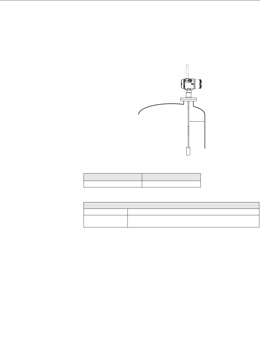
PRELIMINARY
Free Space For easy access to the transmitter make sure that it is mounted with sufficient
service space. For maximum measurement performance the transmitter
should not be mounted too close to the tank wall or other objects in the tank.
If the probe is mounted close to a wall, nozzle or other tank obstruction noise
might appear in the level signal. Therefore the following minimum clearance,
according to the table below, must be maintained:
Figure 4-5. Free Space
Requirement
Table 4-2. Recommended
minimum free space L to tank
wall or other objects in the tank.
Table 4-3. Recommended
minimum free space L to tank
wall or other objects in the tank
for Single Lead probes.
L
Coaxial Flexible Twin
0 in. (0 mm) 4 in. (100 mm)
Rigid Single/Flexible Single
4 in. (100 mm) Smooth metal wall.
12 in. (300 mm) Disturbing objects such as pipes and beams, concrete or plastic tank
walls, rugged metal tank walls.
Reference Manual
00809-XXXX-4811, Rev AA
February 2012
Rosemount 3308
4-10
PRELIMINARY
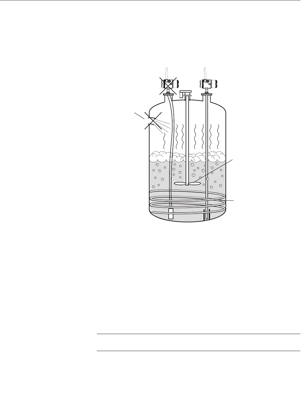
Recommended Mounting
Position When finding an appropriate mounting position for the transmitter the
conditions of the tank must be carefully considered. The transmitter should be
mounted so that the influence of disturbing objects is reduced to a minimum.
In case of turbulence the probe may need to be anchored to the bottom. See
“Mechanical Installation“ on page 4-11 for more information.
Figure 4-6. Mounting Position
The following guidelines should be considered when mounting the transmitter:
• Do not mount close to inlet pipes.
• Do not mount close to agitators. If the probe can move to within
12 in. (30 cm) away from an agitator a probe tie-down is
recommended.
• If the probe tends to sway due to turbulent conditions in the tank, the
probe should be anchored to the tank bottom.
• Avoid mounting close to heating coils.
• Make sure that the nozzle does not extend into the tank.
• Make sure that the probe does not come into contact with the nozzle or
other objects in the tank.
• Position the probe such that it is subject to a minimum of lateral force.
NOTE!
Violent fluid movements causing high sideway forces may break rigid probes.
Inlet pipe
Heating coils
Agitator
Reference Manual
00809-XXXX-4811, Rev AA
February 2012
4-11
Rosemount 3308
PRELIMINARY
MECHANICAL
INSTALLATION Mount the transmitter with flange on a nozzle on top of the tank. The
transmitter can also be mounted on a threaded connection. Make sure only
qualified personnel perform the installation.
NOTE
If you need to remove the transmitter head from the probe, make sure that the
Process Seal is carefully protected from dust and water. See “Service“ on
page 7-9 for further information.
Figure 4-7. Threaded tank
connection.
1. For tank connections with BSP/G threads,
place a gasket on top of the tank flange, or
use a sealant on the threads of the tank
connection.
2. Lower the transmitter and probe into the
tank.
3. Screw the adapter into the process
connection.
4. Loosen the nut that connects the
transmitter housing to the probe slightly.
5. Rotate the transmitter housing so the
cable entries/display face the desired
direction.
6. Tighten the nut.
7. Continue with the Power Module
Installation.
NOTE!
For adapters with NPT threads, pressure-tight
joints require a sealant.
Sealant on threads or
gasket (for BSP/G threads)
Nut
Tank connection
Probe
Reference Manual
00809-XXXX-4811, Rev AA
February 2012
Rosemount 3308
4-12
PRELIMINARY
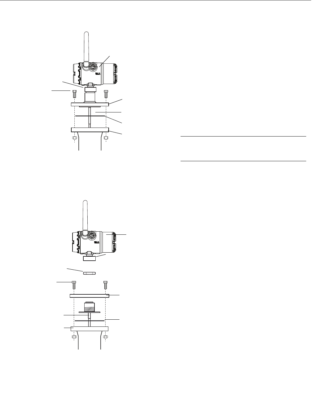
Figure 4-8. Tank connection with
flange.
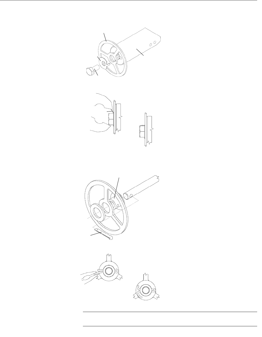
Figure 4-9. Tank connection with
loose flange (“plate design”).
1. Place a gasket on top of the tank flange.
2. Lower the transmitter and probe with
flange into the tank.
3. Tighten the bolts.
4. Loosen the nut that connects the
transmitter housing to the probe slightly.
5. Rotate the transmitter housing so the
cable entries/display face the desired
direction.
6. Tighten the nut.
7. Continue with the Power Module
Installation.
NOTE!
PTFE covered probes must be handled
carefully to prevent damage to the coating.
Transmitter head
Gasket
Flange
Tank flange
Nut
Probe
Bolts
The transmitter is delivered with head, flange
and probe assembled into one unit. If, for
some reason, these parts have been
disassembled mount the transmitter as
described below:
1. Place a gasket on top of the tank flange.
2. Mount the flange on the probe and
tighten the flange nut.
3. Mount the transmitter head.
4. Lower the transmitter and probe with
flange into the tank.
5. Tighten the bolts.
6. Loosen the nut that connects the
transmitter housing to the probe slightly.
7. Rotate the transmitter housing so the
cable entries/display face the desired
direction.
8. Tighten the nut.
9. Continue with the Power Module
Installation.
Transmitter head
Gasket
Flange
Tank flange
Probe
Flange nut
Bolts
Nut
Reference Manual
00809-XXXX-4811, Rev AA
February 2012
4-13
Rosemount 3308
PRELIMINARY
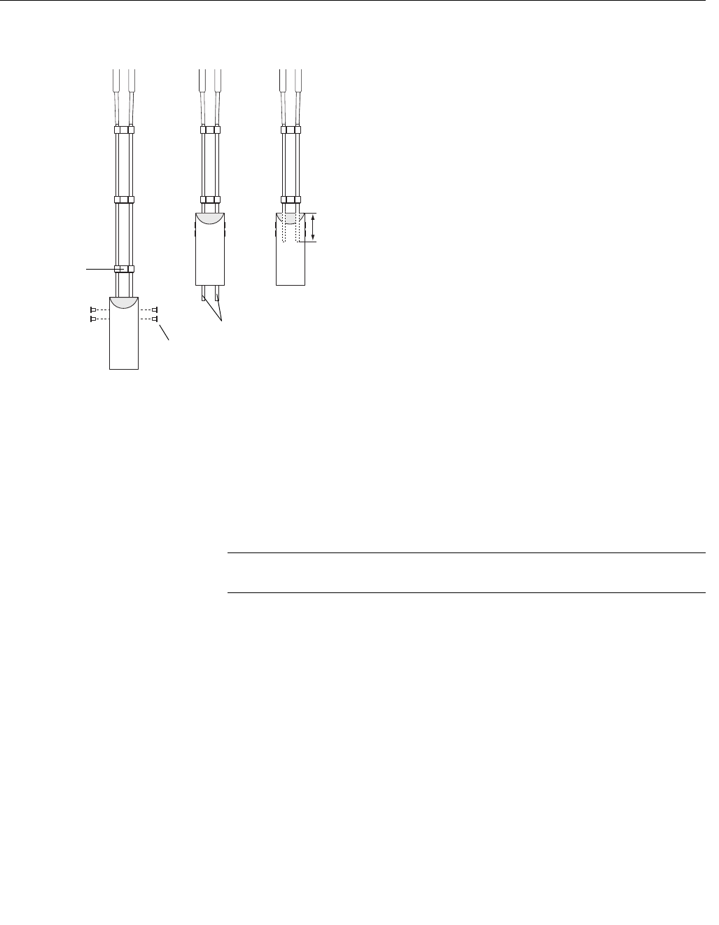
Shortening the Probe Flexible Twin/Single Lead
Rigid Single Lead
1. Cut the Single Lead probe to the desired length.
2. Update the transmitter configuration to the new probe length, see “Probe
Length“ on page 5-9.
NOTE!
The PTFE covered probes must not be cut in field.
1. Mark off the required probe length. Add at
least 1.6 in. (40 mm) to the required probe
length to be inserted into the weight.
2. Loosen the Allen screws.
3. Slide the weight upwards as much as
needed in order to cut the probe.
4. Cut the probe. The minimum probe length
is 3.33 ft (1 m). If necessary, remove a
spacer to make room for the weight.
5. Slide the weight down to the required
cable length.
6. Tighten the screws.
7. Update the transmitter configuration to the
new probe length, see “Probe Length“ on
page 5-9.
If the weight was removed from the cables
when cutting, make sure that at least 1.6 in.
(40 mm) of the cable is inserted when the
weight is replaced.
Allen
screws
Minimum:
1.6 in.
(40 mm)
Spacer
Cut
Reference Manual
00809-XXXX-4811, Rev AA
February 2012
Rosemount 3308
4-14
PRELIMINARY
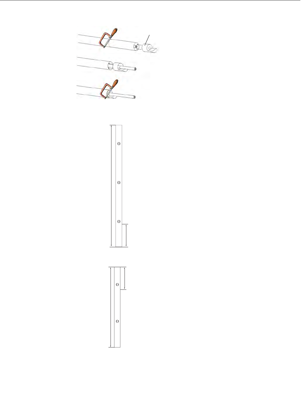
Coaxial
To cut a coaxial probe do the
following:
1. Insert the centering piece.
(The centering piece is
delivered from factory and
should be used to prevent the
spacers centering the rod from
coming loose).
2. Cut the tube to the desired length.
3. Move the centering piece.
4. Cut the rod inside the tube. Make
sure that the rod is fixed with the
centering piece while cutting.
• Pipes longer than
49 in. (1250 mm) can be
shortened by as much as
23.6 in. (600 mm).
• Pipes shorter than
49 in. (1250 mm) can be cut as
long as the remaining length is not
less than
15.7 in. (400 mm).
5. Update the transmitter
configuration to the new probe
length, see “Probe Length“ on
page 5-9.
Centering piece
Maximum shortening
23.6 in. (600 mm)
L > 49 in.
(1250 mm)
Minimum probe length
15.7 in. (400 mm)
L 49 in.
(1250 mm)
Reference Manual
00809-XXXX-4811, Rev AA
February 2012
4-15
Rosemount 3308
PRELIMINARY
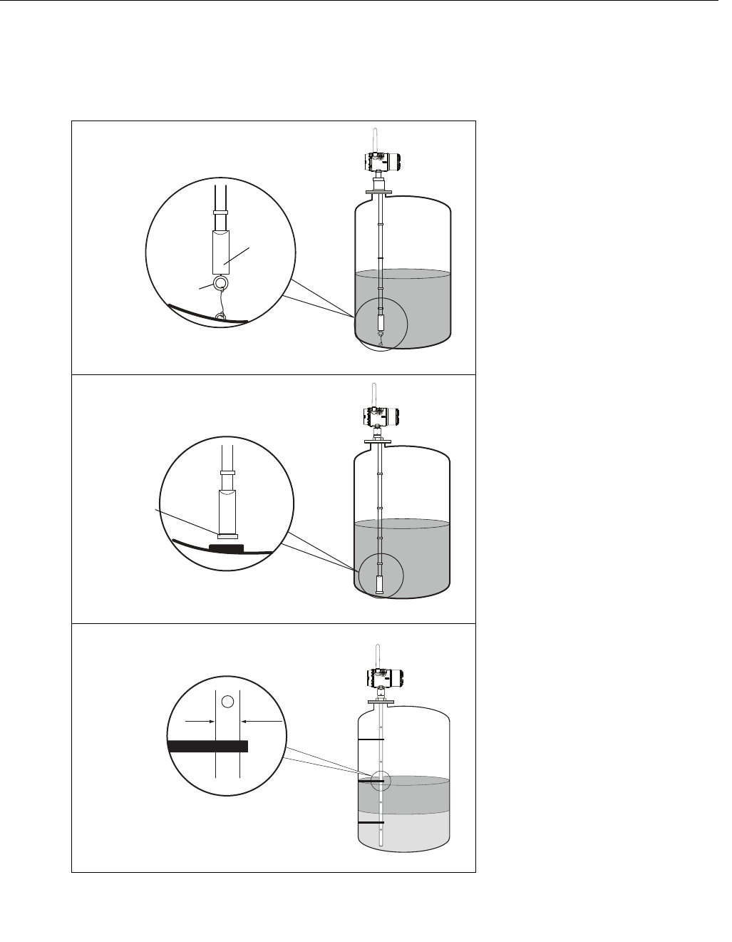
Anchoring In turbulent tanks it may be necessary to fix the probe. Depending on the
probe type different methods can be used to guide the probe to the tank
bottom. This may be needed in order to prevent the probe from hitting the
tank wall or other objects in the tank, as well as preventing a probe from
breaking.
Flexible Twin/Single Lead probe
with weight and ring.
A ring (customer supplied) can be
attached to the weight in a threaded
(M8x14) hole at the end of the
weight. Attach the ring to a suitable
anchoring point.
Flexible Twin/Single Lead probe
with weight and magnet.
A magnet (customer supplied) can
be fastened in a threaded (M8x14)
hole at the end of the weight. The
probe can then be guided by placing
a suitable metal plate beneath the
magnet.
Coaxial probe fixed to the tank wall.
The coaxial probe can be guided to
the tank wall by fixtures fastened to
the tank wall. Fixtures are customer
supplied. Make sure the probe can
move freely due to thermal
expansion without getting stuck in
the fixture.
Weight with
internal threads
M8x14
Ring
Magnet
1.1 in. (28 mm)
Reference Manual
00809-XXXX-4811, Rev AA
February 2012
Rosemount 3308
4-16
PRELIMINARY
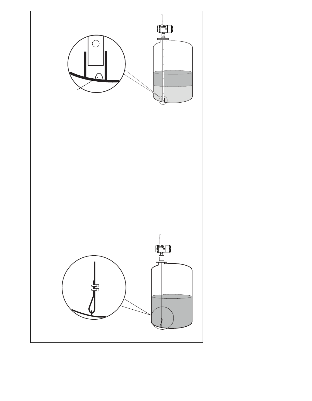
Coaxial probe.
The Coaxial probe can be guided by
a tube welded on the tank bottom.
Tubes are customer supplied. Make
sure that the probe can move freely
in order to handle thermal expansion.
Flexible Single Lead probe with
weight.
TO BE ADDED
Flexible Single Lead probe.
The probe rope itself can be used for
anchoring. Pull the probe rope
through a suitable anchoring point,
e.g. a welded eye and fasten it with
two clamps.
The length of the loop will add to the
transition zone.The location of the
clamps will determine the beginning
of the transition zone. The probe
length should be configured as the
length from the underside of the
flange to the top clamp. See section
“Transition Zones“ on page 2-12 for
further information on Transition
Zones.
Drain
Reference Manual
00809-XXXX-4811, Rev AA
February 2012
4-17
Rosemount 3308
PRELIMINARY
Mounting a Centering
Disc for Pipe
Installations
Flexible Single/Twin Lead probe
Rigid Single Lead probe
NOTE!
Centering discs may not be used with PTFE covered probes.
1. Mount the centering disc at the
end of the weight.
2. Make sure that the tab washer is
properly inserted in the centering
disc.
3. Fasten the centering disc with
the bolt.
4. Secure the bolt by folding the tab
washer.
Centering disc
Weight
Bolt
Tab washer
Tab washer
1. Mount the centering disc at the
end of the probe.
2. Fasten the disc by inserting the
split pin through the bushing
and the probe.
3. Secure the split pin.
Bushing
Split pin

Reference Manual
00809-XXXX-4811, Rev AA
February 2012
Rosemount 3308
4-18
PRELIMINARY
LCD DISPLAY NOTE!
Do not remove the instrument cover in explosive environments when the
circuit is live.
General If the LCD display is ordered in the transmitter model number (option code
M5), it will be shipped attached to the transmitter.
NOTE
If ordering spare parts for a replacement LCD, only use Rosemount Wireless
LCD Part Number: 00753-9004-0002. This will provide a replacement
LCD/electronics board, and LCD pin connector.
LCD Rotation The optional LCD display can be rotated in 90-degree increments by
squeezing the two black tabs on opposite sides of the display, gently pulling
out the display, rotating to the desired orientation, and snapping back the
display into place. Refer to Figure 4-10 for a graphical illustration.
Figure 4-10. LCD Rotation
If the LCD pins are inadvertently removed from the interface board, carefully
re-insert the pins before snapping the LCD display back into place.
Retrofitting If an existing transmitter with no display (flat electronics cover) is to be
retrofitted with a new display, order spare part number 00753-9004-0001. This
kit contains an extended aluminum cover with an LCD viewing window, an
LCD/electronics board, and an LCD pin connector. The contents of this kit are
shown in Figure 4-11.
Figure 4-11. LCD Display
Retrofit Kit
To install the LCD display, remove the electronics-side flat cover. Insert the
four-pin connector into the LCD display, rotate the LCD to the desired
orientation, and gently snap into place. Replace the flat cover with the LCD
cover and tighten. Refer back to Figure 4-10 for a graphical illustration.
LCD Configuration How to configure parameters displayed, update rate, always off, etc.
LCD Display LCD Cover
LCD
Pins
LCD Display
LCD Cover
LCD
Pins

Reference Manual
00809-XXXX-4811, Rev AA
February 2012
4-19
Rosemount 3308
PRELIMINARY
GROUND THE
TRANSMITTER The Rosemount 3308 Wireless Guided Wave Radar transmitter operates with
the housing grounded or floating. Floating systems can cause extra noise that
may affect many types of readout devices. If the signal appears noisy or
erratic, grounding at a single point may solve the problem. Grounding of the
electronics enclosure should be done in accordance with local and national
installation codes. Grounding is accomplished through the process
connection using the internal or external case grounding terminal.
How to Ground the
Device Procedure to be added.
NOTE
Always use facility recommended wiring practices.

Reference Manual
00809-XXXX-4811, Rev AA
February 2012
Rosemount 3308
4-20
PRELIMINARY
Reference Manual
00809-XXXX-4811, Rev AA
February 2012 Rosemount 3308
www.rosemount.com
PRELIMINARY
Section 5 Start-Up/Commissioning
Safety messages . . . . . . . . . . . . . . . . . . . . . . . . . . . . . . . . . page 5-1
Device Network Configuration . . . . . . . . . . . . . . . . . . . . . page 5-2
Configuration Parameters . . . . . . . . . . . . . . . . . . . . . . . . . page 5-3
Configuration using a Field Communicator . . . . . . . . . . . page 5-8
Verify Operation . . . . . . . . . . . . . . . . . . . . . . . . . . . . . . . . . page 5-14
SAFETY MESSAGES Procedures and instructions in this section may require special precautions to
ensure the safety of the personnel performing the operations. Information that
raises potential safety issues is indicated by a warning symbol ( ). Refer to
the safety messages listed at the beginning of each section before performing
an operation preceded by this symbol.
Failure to follow safe installation and servicing guidelines could result in death or
serious injury:
Make sure only qualified personnel perform the installation.
Use the equipment only as specified in this manual. Failure to do so may impair the
protection provided by the equipment.
Do not perform any service other than those contained in this manual unless you are
qualified.
Explosions could result in death or serious injury:
Installation of this transmitter in an explosive environment must be in accordance with
the appropriate local, national, and international standards, codes, and practices.
Please review the Product Certifications section for any restrictions associated with a
safe installation.
• Before connecting a Field Communicator in an explosive atmosphere, ensure
the instruments are installed in accordance with intrinsically safe or
non-incendive field wiring practices.
• In an Explosion-proof/Flameproof installation, do not remove the transmitter
cover when power is applied to the unit.
Process leaks may cause harm or result in death:
• Do not remove the transmitter while in operation
• Install device prior to process start-up
Electrical shock could cause death or serious injury:
• Avoid contact with the leads and terminals. High voltage that may be present
on leads can cause electrical shock.
This device complies with Part 15 of the FCC Rules. Operation is subject to the following
conditions: This device may not cause harmful interference. This device must accept
any interference received, including interference that may cause undesired operation.
This device must be installed to ensure a minimum antenna separation distance of 20
cm (8 in.) from all persons.
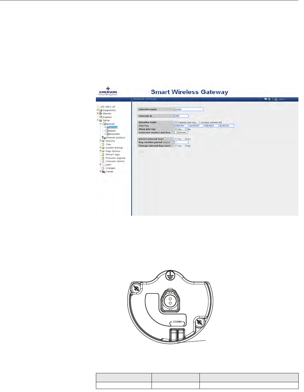
Reference Manual
00809-XXXX-4811, Rev AA
February 2012
Rosemount 3308
5-2
PRELIMINARY
DEVICE NETWORK
CONFIGURATION To communicate with the Gateway, and ultimately the host system, the
transmitter must be configured to communicate with the wireless network.
Using a Field Communicator or AMS Wireless Configurator, enter the
Network ID and Join Key so they match the Network ID and Join Key of the
Gateway and the other devices in the network. If the Network ID and Join Key
are the same as the Gateway, the transmitter will not communicate with the
network. The Network ID and Join Key may be obtained from the Gateway on
the Setup>Network>Settings page on the Gateway's integrated web server,
shown in Figure 5-1.
Figure 5-1. Gateway Network
Settings
AMS Right click on the Rosemount 3308 transmitter and select Configure. When
the menu opens, select Join Device to Network and complete the method to
enter the Network ID and Join Key.
Field Communicator Connect the field communicator leads to the COMM terminals on the terminal
block as shown in Figure 5-2.
Figure 5-2. Terminal Block with
COMM terminals
The Network ID and Join Key may be changed in the wireless device on a
Field Communicator by using the Fast Key Sequence shown in Table 5-1.
Table 5-1. Rosemount 3308
Fast Key Sequence
P/N 00753-9200-2410
COMM terminals
Function Key Sequence Menu Items
Join Device to Network 2, 1, 2 Network ID, Set Join Key
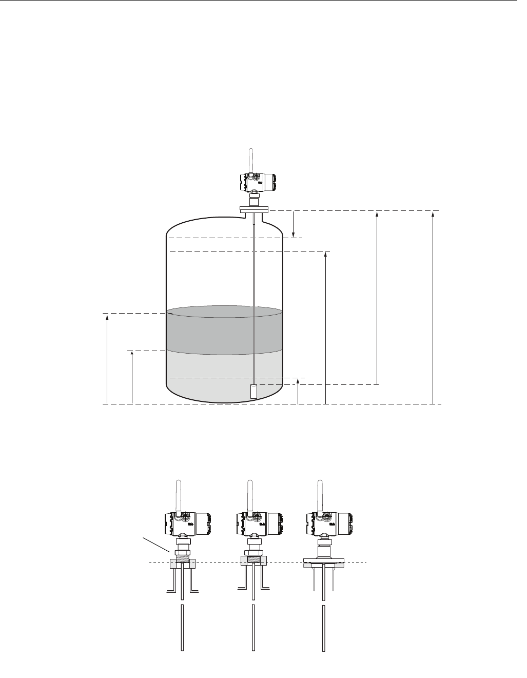
Reference Manual
00809-XXXX-4811, Rev AA
February 2012
5-3
Rosemount 3308
PRELIMINARY
CONFIGURATION
PARAMETERS The Rosemount 3308 transmitter can be configured for level, volume,
interface level, and interface distance measurements.
The Rosemount 3308 transmitter can be pre-configured according to the
ordering specifications in the Configuration Data Sheet.
Basic Configuration The basic transmitter configuration includes setting the tank geometry
parameters. For interface measurements the dielectric constant of the top
liquid must also be given. For some applications with heavy vapor, the vapor
dielectric must be given as well.
Figure 5-3. Tank Geometry
Figure 5-4. Upper Reference
Point For the different tank connections the Upper Reference Point is located at the
underside of the threaded adapter or at the underside of the welded flange, as
illustrated in Figure 5-4:
LRV
URV
Tank Height
Upper Null Zone
Product Level
Upper Reference Point
Lower Reference Point
Interface
Level
Probe
Length
NPT BSP (G) FLANGE
Upper Reference Point
Adapter

Reference Manual
00809-XXXX-4811, Rev AA
February 2012
Rosemount 3308
5-4
PRELIMINARY
Tank Height
The Tank Height is the distance from the Upper Reference Point to the bottom
of the tank. The transmitter measures the distance to the product surface and
subtracts this value from the Tank Height to determine the level.
Probe Length
The probe length is the distance between the Upper Reference Point and the
end of the probe. If a weight is used at the end of the probe it shall not be
included.
This parameter is pre-configured at factory. It must be changed if the probe is
shortened.
Probe Type
The transmitter is designed to optimize measurement performance for each
probe type.
This parameter is pre-configured at factory. This value needs to be changed if
the probe type is changed.
Dielectric Constant of Upper Product
For interface measurements the dielectric constant of the upper product is
essential in order to obtain good accuracy. See section “Interface” on
page 2-7 for further information on dielectric constants.
If the dielectric constant of the lower product is significantly smaller than the
dielectric constant of water, you may need to make special adjustments. See
section “Interface Measurements for Semi-Transparent Bottom Products” on
page 7-5 for further information.
For level measurements the Upper Product Dielectric parameter corresponds
to the actual dielectric constant of the product in the tank. Normally this
parameter does not need to be changed even if the actual dielectric constant
of the product deviates from the Upper Product Dielectric parameter value.
However, for some products measurement performance can be optimized by
setting the proper product dielectric constant.
Dielectric Constant of Vapor
In some applications there is heavy vapor above the product surface having a
significant influence on the level measurement. In such cases the vapor
dielectric can be entered to compensate for this effect.
The default value is equal to 1 which corresponds to the dielectricity of
vacuum. Normally this value does not need to be changed since the effect on
measurement performance is very small for most vapors.

Reference Manual
00809-XXXX-4811, Rev AA
February 2012
5-5
Rosemount 3308
PRELIMINARY
Upper Null Zone
This parameter should only be changed if there are measurement problems in
the upper part of the tank. Such problems may occur if there are disturbing
objects close to the probe. By setting the Upper Null Zone, the measuring
range is reduced. See Section 7: Disturbances at the Top of the Tank for
further information.
NOTE
Measurements are not performed within the Upper Null Zone.
Probe angle
If the transmitter is not mounted vertically, the angle from the vertical position
must be given.

Reference Manual
00809-XXXX-4811, Rev AA
February 2012
Rosemount 3308
5-6
PRELIMINARY
Volume Configuration For volume calculations you can choose one of the standard tank shapes or
the strapping option. Choose None if volume calculation is not used.
Tank Type
You can choose one of the following options:
• Strap table
• Vertical Cylinder
• Horizontal Cylinder
• Vertical Bullet
• Horizontal Bullet
• Sphere
•None
Strapping Table
Use a strapping table if a standard tank type does not provide sufficient
accuracy. Use most of the strapping points in regions where the tank shape is
non-linear. A maximum of 10 points can be added to the strapping table.
Figure 5-5. Strapping points
Actual tank bottom may look like this.
Using only 3 strapping points results in a level-to-volume profile
that is more angular than the actual shape.
Using 6 of the points at the bottom of the tank yields a
level-to-volume profile that is similar to the actual tank bottom.
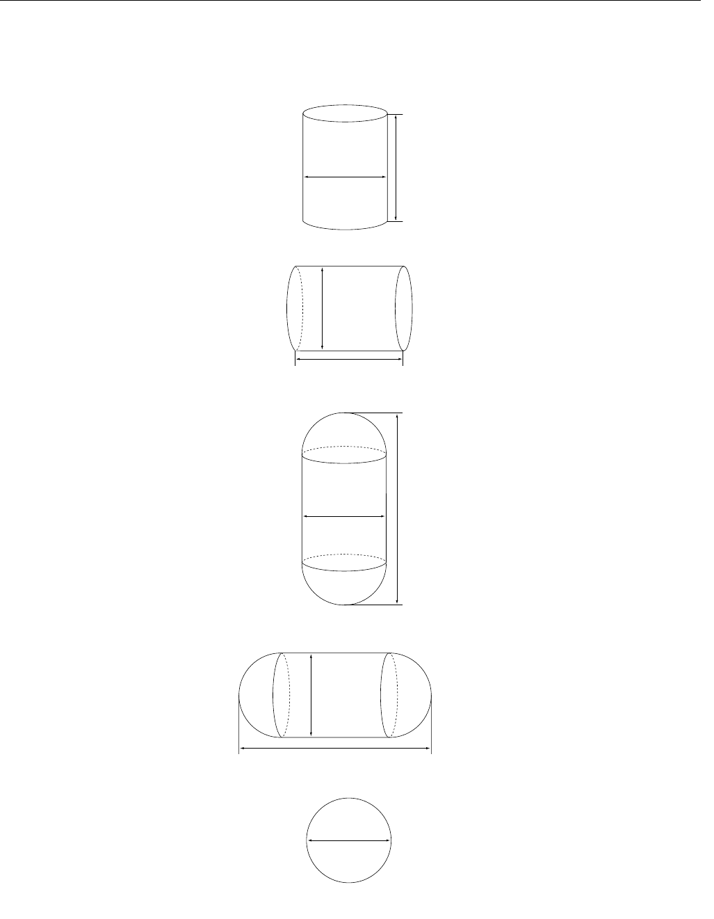
Reference Manual
00809-XXXX-4811, Rev AA
February 2012
5-7
Rosemount 3308
PRELIMINARY
Standard Tank Shapes
Figure 5-6. Standard tank
shapes
Vertical Cylinder
Vertical Cylinder tanks are specified by
Diameter and Height.
Horizontal Cylinder
Horizontal Cylinders are specified by
Diameter and Height.
Vertical Bullet
Vertical Bullet tanks are specified by
Diameter and Height. The volume
calculation model for this tank type
assumes that the radius of the bullet
end is equal to the Diameter/2.
Horizontal Bullet
Horizontal Bullets are specified by
Diameter and Height. The volume
calculation model for this tank type
assumes that the radius of the bullet
end is equal to the Diameter/2.
Sphere
Spherical tanks are specified by
Diameter.
Diameter Height
Diameter
Height
Diameter Height
Diameter
Height
Diameter
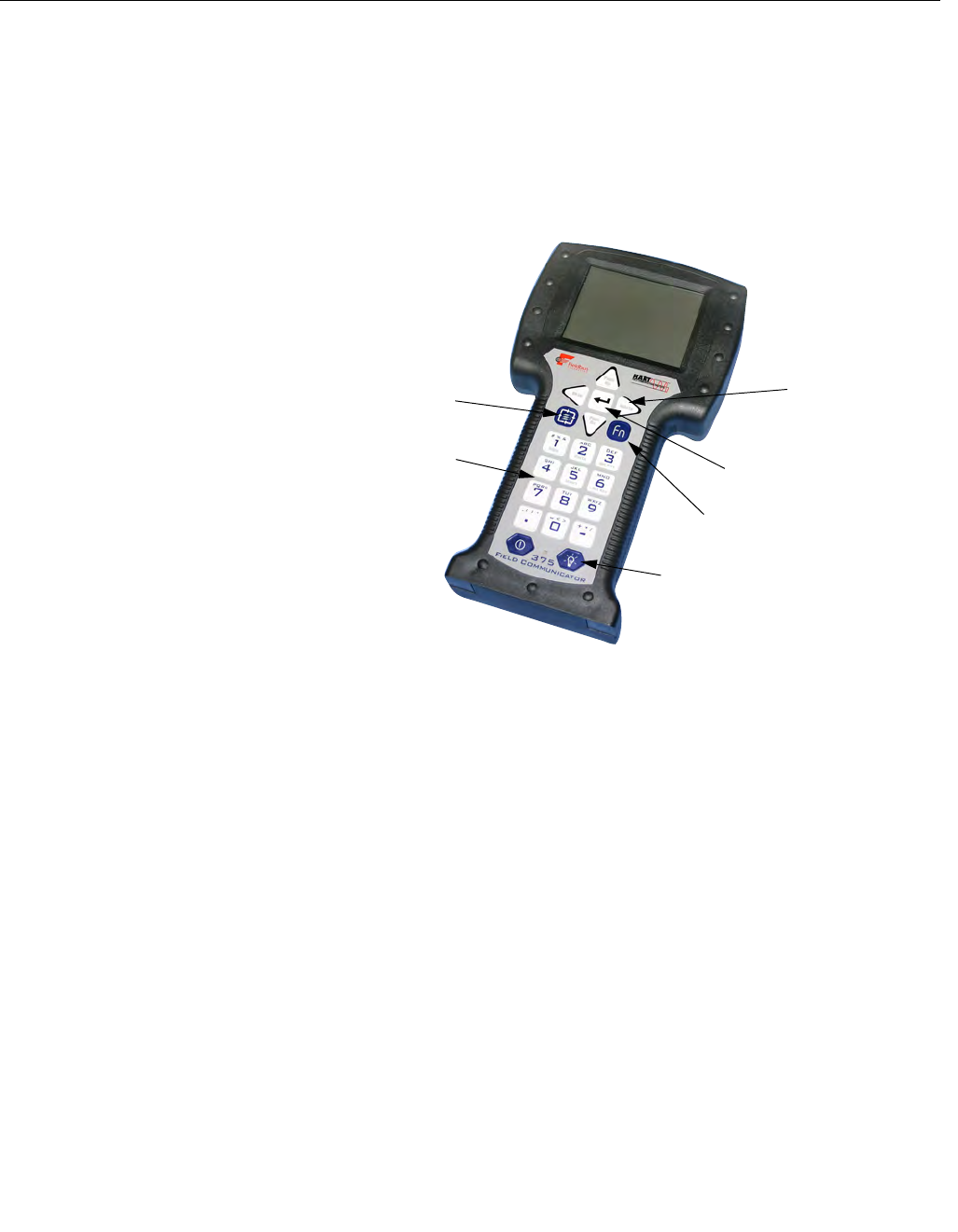
Reference Manual
00809-XXXX-4811, Rev AA
February 2012
Rosemount 3308
5-8
PRELIMINARY
CONFIGURATION USING
A FIELD
COMMUNICATOR
This section describes how to configure the Rosemount 3308 transmitter by
using a Field Communicator. A HART Communicator may also be used.
For information on all the capabilities, refer to the Field Communicator
Product Manual (Document No. 00809-0100-4276).
Figure 5-7. The Field
Communicator.
Function Key
Navigation Keys
Alphanumeric Keys
Backlight adjustment key
Tab Key
Enter Key
Replace with 475

Reference Manual
00809-XXXX-4811, Rev AA
February 2012
5-9
Rosemount 3308
PRELIMINARY
BASIC CONFIGURATION This section describes the various HART commands used to configure the
Rosemount 3308 transmitter for level measurements. The transmitter outputs
a digital HART wireless signal.
Transmitter Variables
You may assign up to four transmitter variables. Typically, the primary variable
(PV) is configured to be Aggregate Level, Interface Level or Volume.
Measurement Units
Set transmitter units for level and temperature.
Tank Height
The Tank Height is the distance from the Upper Reference Point to the bottom
of the tank (see Figure 5-3 on page 5-3). When setting the Tank Height, keep
in mind that this value is used for all level measurements performed by the
Rosemount 3308 transmitter.
The Tank Height must be set in linear (level) units, such as feet or meters,
regardless of primary variable assignment.
Probe Length
The probe length is the distance from the Upper Reference Point to the end of
the probe, see Figure 5-3. If the probe is anchored to a weight do not include
the height of the weight. This parameter is pre-configured at factory. The
Probe Length needs to be changed if, for example, the probe is shortened.
HART Comm TO BE
ADDED
HART Comm TO BE
ADDED
HART Comm TO BE
ADDED
HART Comm TO BE
ADDED

Reference Manual
00809-XXXX-4811, Rev AA
February 2012
Rosemount 3308
5-10
PRELIMINARY
Probe Type
The transmitter automatically makes an initial calibration based on the type of
probe that is used. This parameter is pre-configured at factory and only needs
to be set if the probe is changed to another type. Choose one of the following
options:
• Flexible Twin
•Coaxial
• Rigid Single, Rigid Single PTFE
• Flexible Single, Flexible Single PTFE
Product Dielectric
For interface measurements the dielectric constant of the upper product is
essential for calculating the interface level and the upper product thickness.
By default the Product Dielectric parameter is about 2.
If the dielectric constant of the lower product is significantly smaller than the
dielectric constant of water, you may need to make special adjustments. See
section “Interface Measurements for Semi-Transparent Bottom Products” on
page 7-5 for further information.The dielectric constant of the product is used
for setting the appropriate signal amplitude thresholds, see Section 7: Service
and Troubleshooting for more information on amplitude threshold settings.
Normally this parameter does not need to be changed for level
measurements. However, for some products measurement performance can
be optimized by setting the proper product dielectric constant.
The AMS Suite software includes a Dielectric Chart which lists the dielectric
constants of a wide range of products. AMS also includes a tool which allows
you to calculate dielectric constants based on measurements of the Upper
Product Thickness.
Vapor Dielectric
In some applications there is heavy vapor above the product surface having a
significant influence on the level measurement. In such cases the vapor
dielectric can be entered to compensate for this effect.
The default value is equal to 1 which corresponds to the dielectric constant of
vacuum. Normally this value does not need to be changed since the effect on
measurement performance is very small for most vapors.
HART Comm TO BE
ADDED
HART Comm TO BE
ADDED
HART Comm TO BE
ADDED

Reference Manual
00809-XXXX-4811, Rev AA
February 2012
5-11
Rosemount 3308
PRELIMINARY
Measurement Mode
Normally the Measurement Mode does not need to be changed. The
transmitter is pre-configured according to the specified model:
Table 5-2. Measurement Mode
Interface Immersed Probe is used for applications where the probe is fully
immersed in liquid. In this mode the transmitter ignores the upper product
level. See Section 7: Interface Measurements with Fully Immersed Probes for
more information.
NOTE!
Only use Interface Immersed Probe for applications where interface is
measured for a fully immersed probe.
Probe Angle
Enter the angle between the probe and the vertical line. The default value is
equal to zero. Do not change this value if the transmitter is mounted with the
probe along the vertical line (which is normally the case).
Maximum Upper Product
Thickness For interface measurements the Maximum Upper Product Thickness
parameter may be used in special cases when the dielectric constant of the
upper product is relatively high. By setting this parameter you can avoid that
interface measurements are getting out of range.
Display
Choose variabels to be displayed.
HART Comm TO BE
ADDED
Model Measurement Mode
3308 Level, Level and Interface(1), Interface Immersed probe
(1) Default setting
HART Comm TO BE
ADDED
HART Comm TO BE
ADDED
HART Comm TO BE
ADDED
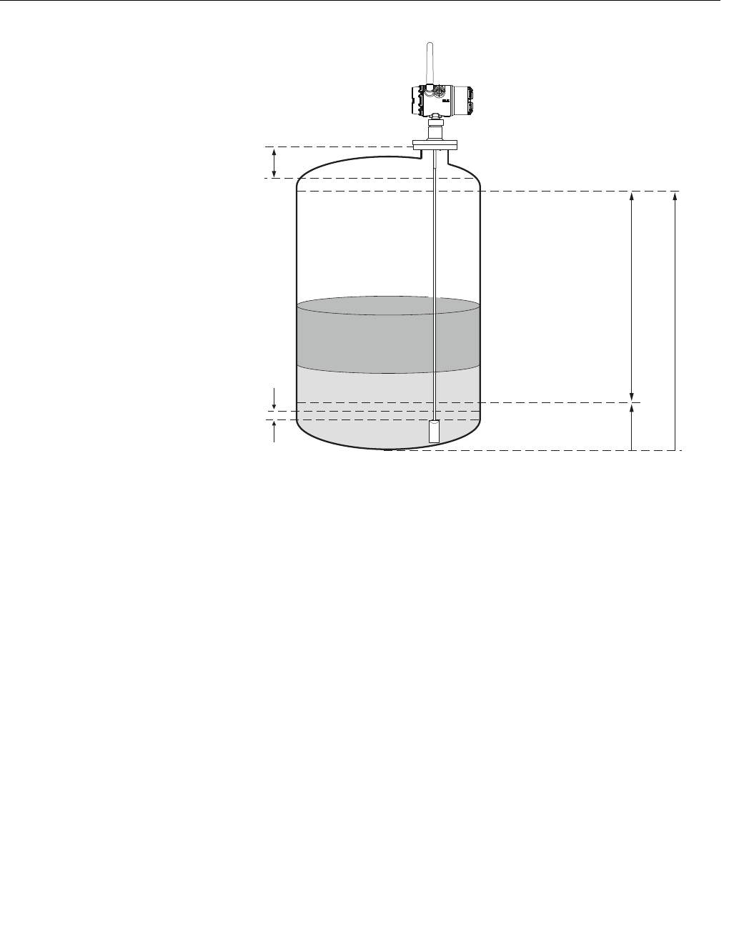
Reference Manual
00809-XXXX-4811, Rev AA
February 2012
Rosemount 3308
5-12
PRELIMINARY
Figure 5-8. Range Values
Upper Range Value (URV)
Upper Transition Zone
Product Level
Interface Level
Lower Transition Zone
Lower Range Value (LRV)
Upper Reference Point
Range 0-100 %

Reference Manual
00809-XXXX-4811, Rev AA
February 2012
5-13
Rosemount 3308
PRELIMINARY
VOLUME
CONFIGURATION
Transmitter Variables
Select the Volume option in order to configure the transmitter for volume
measurements.
Volume Units
Choose one of the following units:
• Gallons
•Liters
• Imperial Gallons
• Cubic Meters
•Barrels
•Cubic Yards
• Cubic Feet
• Cubic Inch
Tank Type
Choose a standard tank shape, or select the strapping option. Standard
shapes are: Vertical Cylinder, Horizontal Cylinder, Vertical Bullet, Horizontal
Bullet or Sphere. (If Primary Variable is Level choose None for Tank Type).
If your tank does not correspond to any of the above tank shapes, select Strap
Table.
Tank Dimensions
If a standard tank type was chosen, enter the diameter and height of the tank.
See “Volume Configuration” on page 5-6 for information on how to specify
tank dimensions.
Strapping Table
If tank type Strapping Table was chosen, enter how many entries you will use
and the actual level and volume points. You can enter from 2 to 10 points. The
strapping points must be entered such that the first point corresponds to the
lowest level, and the last point corresponds to the topmost level of the tank.
HART Comm TO BE
ADDED
HART Comm TO BE
ADDED
HART Comm TO BE
ADDED
HART Comm TO BE
ADDED
HART Comm TO BE
ADDED

Reference Manual
00809-XXXX-4811, Rev AA
February 2012
Rosemount 3308
5-14
PRELIMINARY
VERIFY OPERATION Operation can be verified in four ways, further described in this section:
1. At the device with the local display
2. Using the Field Communicator
3. In the Smart Wireless Gateway's integrated web interface
4. Using the AMS® Suite Wireless Configurator or AMS Device Manager
If the Rosemount 3308 was configured with the Network ID and Join Key, and
sufficient time has passed, the transmitter will be connected to the network. If
Network ID and Join Key were not configured, please see “Troubleshooting”
on page 5-16.
Verification by LCD To verify operation at the device with the local display, confirm that the display
is showing a value. If the device is connected, the default LCD configuration
displays the primary variable (PV) value at the configured update rate.
illustrates the display messages that may be shown in the various stages of
the device's network connection. Refer to Section 6: Operation and
Maintenance for a full listing of error codes and other LCD messages. Press
the Diagnostic button to display the TAG, Device ID, Network ID, Network Join
Status, and Device Status screens.
Figure 5-9. Network Connection
LCD Display Messages
Field Communicator
Verification For HART Wireless transmitter communication, a Rosemount 3308 DD is
required. To obtain the latest DD, visit the Emerson Process Management
Easy Upgrade site at:
http://www2.emersonprocess.com/en-US/documentation/deviceinstallkits.
Connect the Field Communicator as shown on in Figure 5-2 on page 5-2 of
this document. Do not remove the Power Module. Removing the Power
Module may cause the device to drop off the network.
NOTE
In order to communicate with a Field Communicator, the device must be
powered by connecting the Power Module.
Enter the Field Communicator menu and use the Fast Key Sequence in
Table 5-3 to navigate to the Communications menu items. Select the
Communication Status parameter to verify operation. The remaining
Communications menu items provide additional network information.
n e t w k
N E G O T
N E T w K
S R C H N G
n e t w k
L I M - O P
n e t w k
O K
Searching for
Network Joining
Network Connected with
Limited Bandwidth Connected
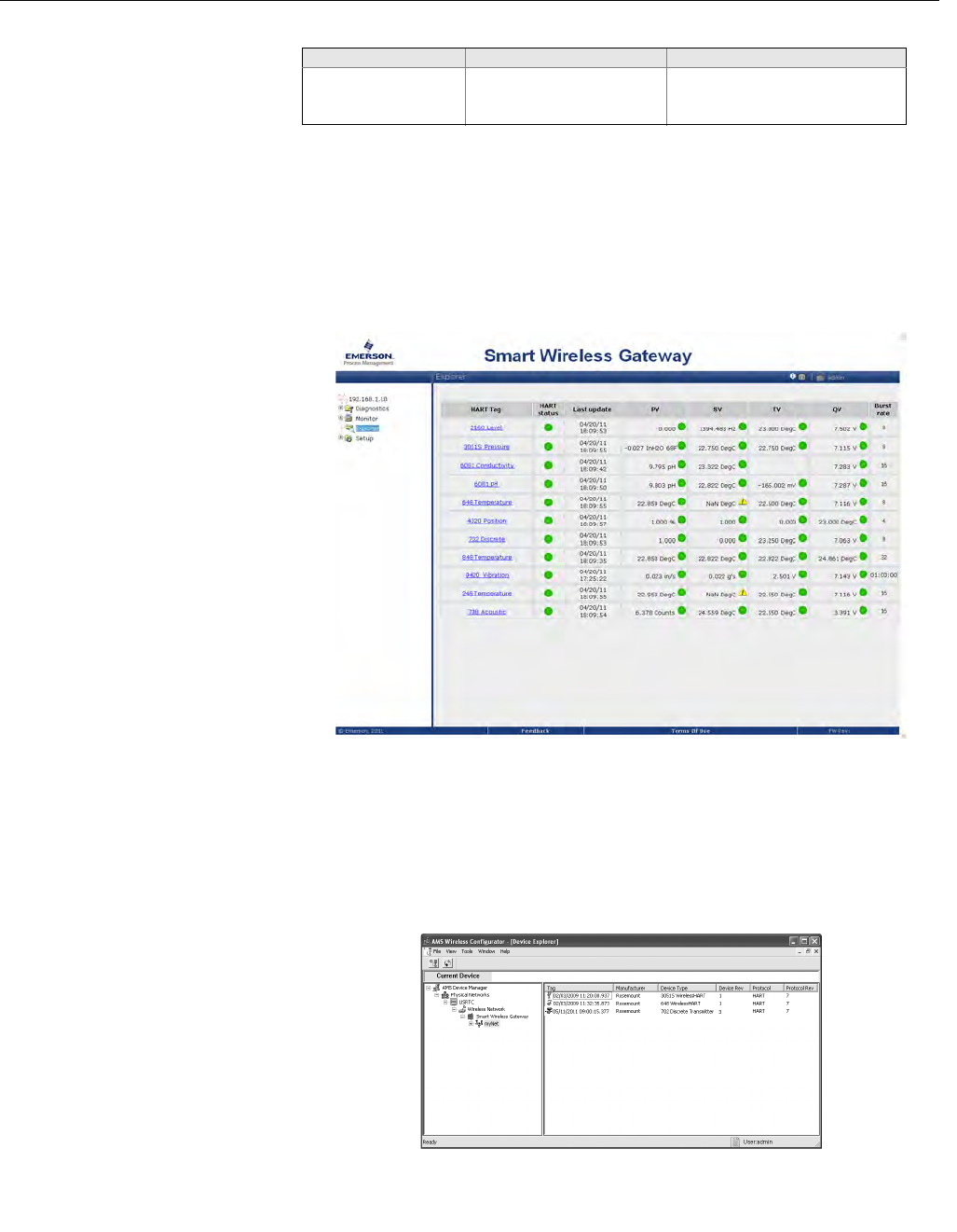
Reference Manual
00809-XXXX-4811, Rev AA
February 2012
5-15
Rosemount 3308
PRELIMINARY
Table 5-3. Rosemount 3308
Communications Fast Key
Sequence
Verification by Gateway Using the Smart Wireless Gateway's integrated web interface, navigate to the
Explorer>Status page as shown in Figure 5-10. This page shows whether
the device has joined the network and if it is communicating properly. Locate
the device in question and verify all status indicators are good (green). It may
take several minutes for the device to join the network and be seen on the
Gateway's integrated web interface.
Figure 5-10. Smart Wireless
Gateway Explorer Status Page
Verification with AMS
Wireless Configurator When the device has joined the network, it will appear in the Wireless
Configurator window as illustrated in Figure 5-11. For HART Wireless
transmitter communication, a 3308A DD is required. To obtain the latest DD,
visit the Emerson Process Management Easy Upgrade site at:
http://www2.emersonprocess.com/en-US/documentation/deviceinstallkits.
Figure 5-11. AMS Wireless
Configurator Screen
Function Key Sequence Menu Items
Communications 3, 3 Join Status, Communication Status,
Join Mode, Number of Available
Neighbors, Number of Advertisements
Heard, Number of Join Attempts

Reference Manual
00809-XXXX-4811, Rev AA
February 2012
Rosemount 3308
5-16
PRELIMINARY
Troubleshooting If the device is not joined to the network after power up, verify the correct
configuration of the Network ID and Join Key, and that Active Advertising has
been enabled on the Smart Wireless Gateway. The Network ID and Join Key
in the device must match the Network ID and Join Key of the Gateway.
Reference the instructions given on page 5-2 for information on configuring
the Network ID and Join Key of the Rosemount 3308.

Reference Manual
00809-XXXX-4811, Rev AA
February 2012 Rosemount 3308
www.rosemount.com
PRELIMINARY
Section 6 Operation and Maintenance
Safety Messages . . . . . . . . . . . . . . . . . . . . . . . . . . . . . . . . . page 6-1
LCD Screen Messages . . . . . . . . . . . . . . . . . . . . . . . . . . . . page 6-2
Display Operation . . . . . . . . . . . . . . . . . . . . . . . . . . . . . . . . page 6-3
Alerts . . . . . . . . . . . . . . . . . . . . . . . . . . . . . . . . . . . . . . . . . . page 6-8
Power Module Replacement . . . . . . . . . . . . . . . . . . . . . . . page 6-10
SAFETY MESSAGES Instructions and procedures in this section may require special precautions to
ensure the safety of the personnel performing the operations. Information that
potentially raises safety issues is indicated by a warning symbol ( ). Please
refer to the following safety messages before performing an operation
preceded by this symbol.
Failure to follow safe installation and servicing guidelines could result in death or
serious injury:
Make sure only qualified personnel perform the installation.
Use the equipment only as specified in this manual. Failure to do so may impair the
protection provided by the equipment.
Do not perform any service other than those contained in this manual unless you are
qualified.
Explosions could result in death or serious injury:
Installation of this transmitter in an explosive environment must be in accordance with
the appropriate local, national, and international standards, codes, and practices.
Please review the Product Certifications section for any restrictions associated with a
safe installation.
• Before connecting a Field Communicator in an explosive atmosphere, ensure
the instruments are installed in accordance with intrinsically safe or
non-incendive field wiring practices.
• In an Explosion-proof/Flameproof installation, do not remove the transmitter
cover when power is applied to the unit.
Process leaks may cause harm or result in death:
• Do not remove the transmitter while in operation
• Install device prior to process start-up
Electrical shock could cause death or serious injury:
• Avoid contact with the leads and terminals. High voltage that may be present
on leads can cause electrical shock.
This device complies with Part 15 of the FCC Rules. Operation is subject to the following
conditions: This device may not cause harmful interference. This device must accept
any interference received, including interference that may cause undesired operation.
This device must be installed to ensure a minimum antenna separation distance of 20
cm (8 in.) from all persons.

Reference Manual
00809-XXXX-4811, Rev AA
February 2012
Rosemount 3308
6-2
PRELIMINARY
LCD SCREEN
MESSAGES
Startup Screen
Sequence The following screens will display when the power module is first connected to
the Rosemount 3308.
All Segments On: used to visually determine if
there are any bad segments on the LCD
Device Identification: used to determine Device
Type.
Device Information - Tag: user entered tag which
is 8 characters long - will not display if all characters
are blank
PV Screen - Measurement of mapped Primary
Variable (default is XX)
X X X X X
X X X X x x x
x x x x x x
702
W I r e l s
A b c d e
f g h
s n s r1
True

Reference Manual
00809-XXXX-4811, Rev AA
February 2012
6-3
Rosemount 3308
PRELIMINARY
DISPLAY OPERATION During steady state operation, the LCD gives a periodic display of
user-chosen variables at the configured wireless update rate. These variables
can be chosen from a list of XX: Level, …………………
The LCD Display will display the variables at the configured update rate, but
no faster than XXX. Refer to page XX for instructions on configuring the
display.
Diagnostic Button
Screen Sequence Detailed diagnostic information can be obtained by removing the display
cover of the Rosemount 3308 transmitter, and momentarily depressing the
"DIAG" button. The LCD will display the diagnostic screens as shown below.
Press the Diagnostic button to display the TAG, Device ID, Network ID,
Network Join Status, and Device Status screens.
The following five screens will display when the device is operating properly
and the Diagnostic Button has been pressed.
SV Screen - Measurement of mapped Second
Variable (default is XX)
Electronics Temperature
Supply Voltage
S N S R 2
True
D E V
2 5. 2 5
d e g c
S u p l y
7. 2 1
v o l t s

Reference Manual
00809-XXXX-4811, Rev AA
February 2012
Rosemount 3308
6-4
PRELIMINARY
Diagnostic Button Screen 1: Tag
Diagnostic Button Screen 2: Device
Identification - used to determine Device ID
Diagnostic Button Screen 3: Network ID
Diagnostic Button Screen 4: the device has
joined a network and has been fully configured and
has multiple parents. Also see “Network
Connection Status Screens” on page 6-5.
Diagnostic Button Screen 5: voltage reading at
the Power Module terminals. Also see
A b c d e
f g h
i d - X X
X X X X X X
n e t w k
13 0 5
I D
n e t w k
O K
S u p l y
7. 2 1
v o l t s
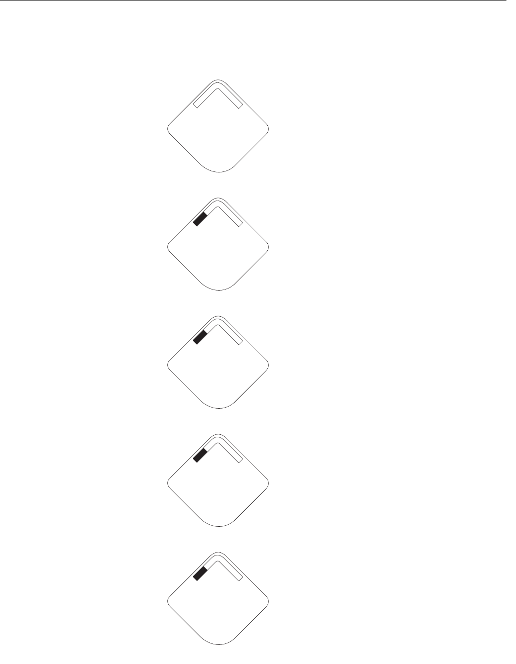
Reference Manual
00809-XXXX-4811, Rev AA
February 2012
6-5
Rosemount 3308
PRELIMINARY
Network Connection
Status Screens One of the following network diagnostic status screens will display in the
fourth position of the Diagnostic Button Screen sequence. The screen
displayed is dependent on the progress of the device in joining the wireless
network.
Diagnostic Button Screen 4.1: the device is still
in the process of being activated
Diagnostic Button Screen 4.2: the device has
just started
Diagnostic Button Screen 4.3: the device has
just started to join the network
Diagnostic Button Screen 4.4: the device is in a
disconnected state and requires a "Force Join"
command to join the network
Diagnostic Button Screen 4.5: the device is
searching for the network
n e t w k
u n k n w n
n e t w k
I N I T
n e t w k
i d l e
n e t w k
D I S C N T
N E T w K
S R C H N G
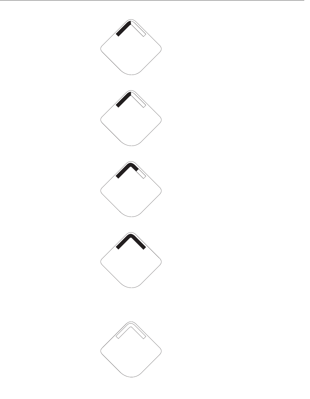
Reference Manual
00809-XXXX-4811, Rev AA
February 2012
Rosemount 3308
6-6
PRELIMINARY
Diagnostic Button
Screen Sequence
(continued)
The following screens will show the device diagnostics depending on the state
of the device, continuing after Diagnostic Button Screen 5.
Diagnostic Button Screen 4.6: the device is
attempting to join a network
Diagnostic Button Screen 4.7: the device is
connected to the network, but is in a “quarantined”
state
Diagnostic Button Screen 4.8: the device is
joined and operational, but is running with limited
bandwidth for sending periodic data
Diagnostic Button Screen 4.9: the device has
joined a network and has been fully configured and
has multiple parents
n e t w k
N E G O T
n e t w k
c o n e c t
n e t w k
L I M - O P
n e t w k
O K
Diagnostic Button Screen 6.1: there is a critical
error which may prevent the electronics board from
operating correctly
b o a r d
f a i l u r

Reference Manual
00809-XXXX-4811, Rev AA
February 2012
6-7
Rosemount 3308
PRELIMINARY
Diagnostic Button Screen 6.2: there is a warning
which should be addressed, but should not affect
the device output.
Diagnostic Button Screen 7.1: the terminal
voltage has dropped below level of operating limit.
Replace the Black Power Module model number
701PBKKF
(Part Number: 00753-9220-0001)
Diagnostic Button Screen 7.2: the terminal
voltage is below the recommended operating
range
- if this is a self-operated device, the power module
should be replaced - for line powered devices, the
supply voltage should be increased
Diagnostic Button Screen 8: the device cannot
retrieve information from the radio in the device -
the device may still be operational and publishing
HART data
Diagnostic Button Screen 9: configuration of the
transmitter is invalid such that critical operation of
the device may be affected - check the extended
configuration status to identify which configuration
item(s) need to be corrected
b o a r d
w a r n
s u p l y
f a i l u r
s u p l y
l o w
r a d i o
f a i l u r
c o n f g
f a i l u r

Reference Manual
00809-XXXX-4811, Rev AA
February 2012
Rosemount 3308
6-8
PRELIMINARY
ALERTS The Rosemount 3308 can be configured to report alerts based on the
measured variables. The Rosemount 3308 also reports diagnostic alerts
when there is a device malfunction. For information on these alerts, refer to
Section 6: Troubleshooting. The following figures show how the AMS Suite
Intelligent Device Manager overview screen looks for each of the alert
conditions.
Diagnostic Button Screen 10: a switch attached
to the transmitter has failed, and valid readings
from that probe are no longer possible - check the
probe and probe wiring connections - check
additional status for more detailed information of
the failure source
Diagnostic Button Screen 11: the device has not
yet received all of the requested wireless
bandwidth needed to operate as configured
Diagnostic Button Screen 12: the device has not
yet received all of the requested wireless
bandwidth needed to operate as configured
Diagnostic Button Screen 13+: all of the periodic
screens except Supply Voltage will now be
displayed to conclude the Diagnostic Button
Screen Sequence. These screens are:
PV Measurement
SV Measurement
Electronics Temperature
s n s r
f a i l u r
B D W T H
L I M I T D
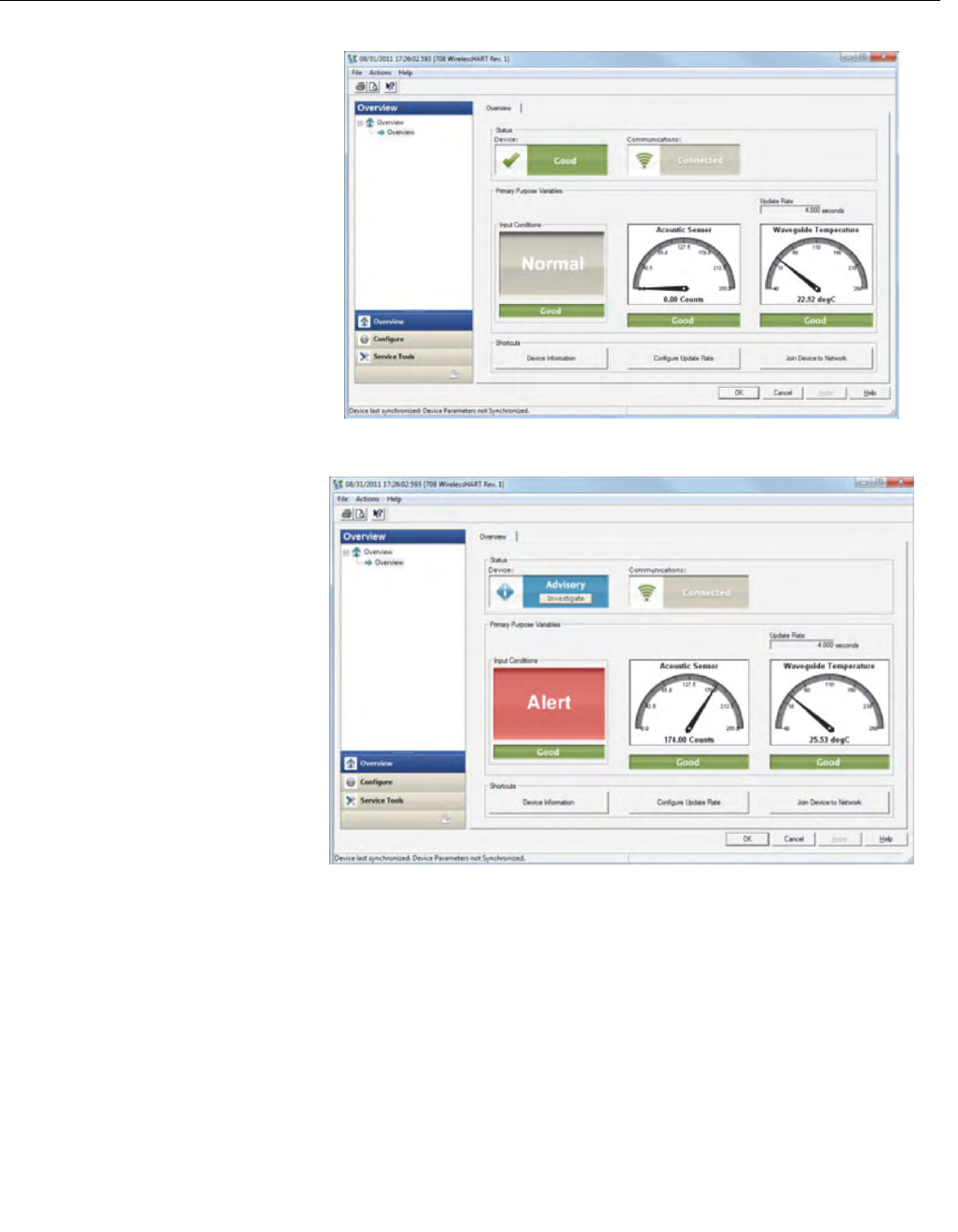
Reference Manual
00809-XXXX-4811, Rev AA
February 2012
6-9
Rosemount 3308
PRELIMINARY
Figure 6-1. AMS Device
Manager Overview Screen,
Normal Conditions
Figure 6-2. AMS Device
Manager Overview Screen, Alert
Conditions
Device Alert
Configuration Alert Levels
The Rosemount 3308 provides 4 user configurable alerts.
HI HI
HI
LO
LO LO explain all and add image.
Alert Setup
There are three methods that can be used to set up these alerts using AMS
Wireless Configurator or a field communicator.
Add methods.

Reference Manual
00809-XXXX-4811, Rev AA
February 2012
Rosemount 3308
6-10
PRELIMINARY
POWER MODULE
REPLACEMENT Expected Power Module life is XX years at reference conditions(1).
Add warnings
When the Power Module needs to be replaced, remove the Power Module
cover and the depleted Power Module. Replace the power module with a new
Black Power Module, SmartPower™ Solutions model number 701PBKKF.
Replace the cover and ensure that the power module cover is fully tightened
to prevent moisture ingress. The lip of the power module cover should be in
contact with the metal enclosure to ensure a proper seal. Do not over tighten.
Handling Considerations
The Black Power Module with the wireless unit contains two "C" size primary
lithium/thionyl chloride batteries. Each battery contains approximately 2.5
grams of lithium, for a total of 5 grams in each Power Module. Under normal
conditions, the battery materials are self-contained and are not reactive as
long as the batteries and the battery pack integrity are maintained. Care
should be taken to prevent thermal, electrical or mechanical damage.
Contacts should be protected to prevent premature discharge.
Use caution when handling the power module, it may be damaged if dropped
from heights in excess of 20 ft (6 m).
Battery hazards remain when cells are discharged.
Environmental Considerations
As with any battery, local environmental rules and regulations should be
consulted for proper management of spent batteries. If no specific
requirements exist, recycling through a qualified recycler is encouraged.
Consult the materials safety data sheet for battery specific information.
Shipping Considerations
The unit was shipped to you without the power module installed. Please
remove the power module prior to shipping.
Each Black Power Module contains two "C" size primary lithium batteries.
Primary lithium batteries are regulated in transportation by the U.S.
Department of Transportation, and are also covered by International Air
Transport Association (IATA), International Civil Aviation Organization (ICAO),
and European Ground Transportation of Dangerous Goods (ARD). It is the
responsibility of the shipper to ensure compliance with these or any other
local requirements. Please consult current regulations and requirements
before shipping.
(1) Reference conditions are 70° F (21° C), transmit rate of once per minute, and routing data
for three additional network devices.

Reference Manual
00809-XXXX-4811, Rev AA
February 2012 Rosemount 3308
www.rosemount.com
PRELIMINARY
Section 7 Service and Troubleshooting
Safety messages . . . . . . . . . . . . . . . . . . . . . . . . . . . . . . . . . page 7-1
Advanced Configuration . . . . . . . . . . . . . . . . . . . . . . . . . . page 7-2
Service . . . . . . . . . . . . . . . . . . . . . . . . . . . . . . . . . . . . . . . . . page 7-9
Diagnostic Messages . . . . . . . . . . . . . . . . . . . . . . . . . . . . . page 7-19
SAFETY MESSAGES Procedures and instructions in this section may require special precautions to
ensure the safety of the personnel performing the operations. Information that
raises potential safety issues is indicated by a warning symbol ( ). Please
refer to the following safety messages before performing an operation
preceded by this symbol.
.
Explosions could result in death or serious injury.
Verify that the operating environment of the gauge is consistent with the appropriate
hazardous locations certifications.
Before connecting a HART-based communicator in an explosive atmosphere, make
sure the instruments in the loop are installed in accordance with intrinsically safe or
non-incendive field wiring practices.
In an Explosion-proof/Flameproof installation, do not remove the transmitter cover when
power is applied to the unit.
Failure to follow safe installation and servicing guidelines could result in death or
serious injury.
Make sure only qualified personnel perform the installation.
Use the equipment only as specified in this manual. Failure to do so may impair the
protection provided by the equipment.
Do not perform any service other than those contained in this manual unless you are
qualified.
High voltage that may be present on leads could cause electrical shock.
Avoid contact with leads and terminals.
Make sure the main power to the Rosemount 3308 transmitter is off and the lines to any
other external power source are disconnected or not powered while wiring
the gauge.
Probes covered with plastic and/or with plastic discs may generate an ignition-capable
level of electrostatic charge under certain extreme conditions. Therefore, when the
probe is used in a potentially explosive atmosphere, appropriate measures must be
taken to prevent electrostatic discharge.
Process leaks could result in death or serious injury.
Make sure that the transmitter is handled carefully. If the Process Seal is damaged, gas
might escape from the tank if the transmitter head is removed from the probe.
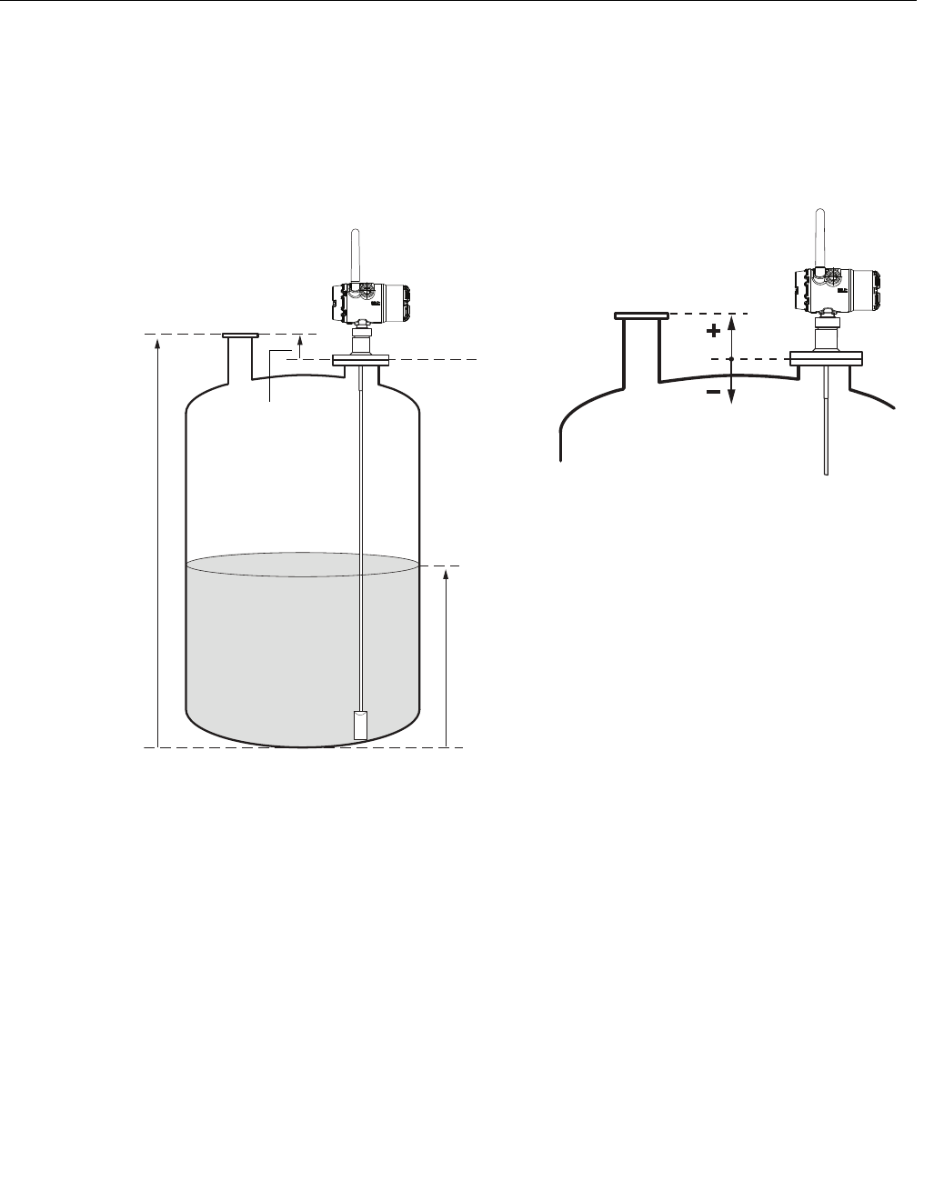
Reference Manual
00809-XXXX-4811, Rev AA
February 2012
Rosemount 3308
7-2
PRELIMINARY
ADVANCED
CONFIGURATION This section covers non-standard configuration.
User defined Upper
Reference Point If you want to specify your own Upper Reference Point you can do this by
setting the Calibration Offset parameter.
Figure 7-1. Tank Geometry
To set the desired upper reference point do the following:
1. Adjust the Tank Height to the distance from the tank bottom to the
desired Upper Reference Point.
2. Add the distance between the Upper Reference Point and the
Transmitter Reference Point to the Calibration Offset value that is
stored in the transmitter database.
With the HART Communicator the Calibration Offset is available as
HART Fast Key sequence [1, 4, 5, 5].
In Radar Configuration Tool (RCT) the Calibration Offset is available
under the Advanced section in the RCT Project Bar:
Device Commands>Basic>Set Calibration Offset.
Tank Height
Product Level
Upper Reference Point Transmitter
Reference Point
Calibration
Offset
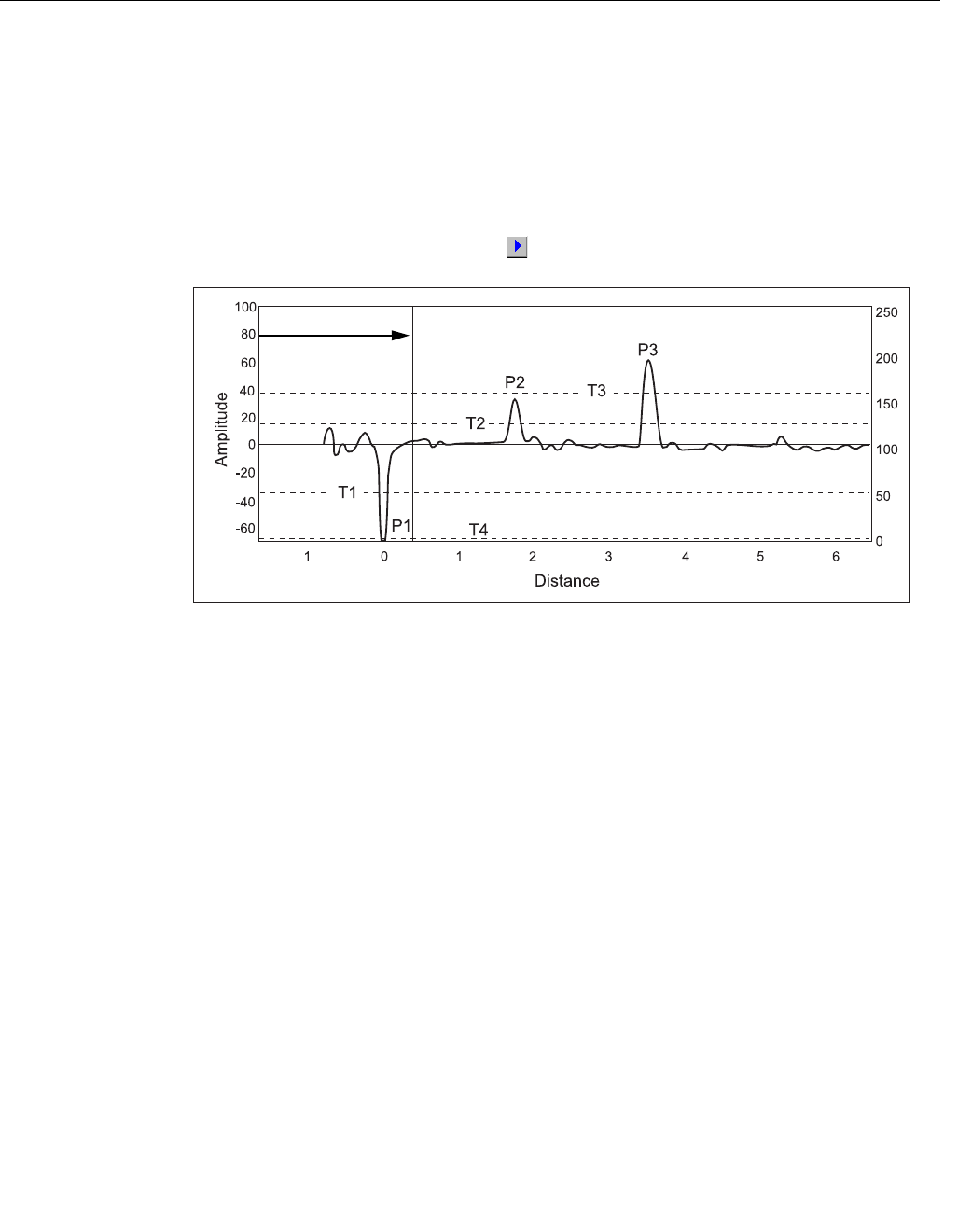
Reference Manual
00809-XXXX-4811, Rev AA
February 2012
7-3
Rosemount 3308
PRELIMINARY
Plotting the
Measurement Signal The Radar Configuration Tool (RCT) has powerful tools for advanced
troubleshooting. By using the Waveform Plot function you get an instant view
of the tank signal. Measurement problems can be solved by studying the
position and amplitude of the different pulses.
To plot the measurement signal:
1. Start the Radar Configuration Tool program.
2. Choose the View>Plotting menu option, or choose the Plotting icon in
the RCT workspace (Advanced page at the left side of the workspace)
and click the Read button.
Figure 7-2. Waveform plot in RCT
In a typical measurement situation the following pulses appear in the diagram:
P1 - Reference pulse. This pulse is caused by the transition between
transmitter head and probe. It is used by the transmitter as a reference at
level measurements.
P2 - Product surface. This pulse is caused by a reflection on the product
surface. In Measurement Mode=Interface when Immersed Probe however, P2
indicates the interface since the surface of the upper product is ignored.
P3 - Interface or probe end. This pulse is caused by reflection on the interface
between an upper product and a bottom product with a relatively high
dielectric constant. It may also be caused by the probe end if there is no
product above. This pulse is shown when the transmitter is in Measurement
Mode=Level & Interface.
Different amplitude thresholds are used in order to filter out unwanted signals.
The following amplitude thresholds are used for the Rosemount 3308
transmitter:
T1 - amplitude threshold for detection of the Reference pulse P1.
T2 - amplitude threshold for detection of the product level peak P2.
T3 - amplitude threshold for detection of the interface level peak P3.
T4 - amplitude threshold that is used to detect whether the probe is fully
immersed in the upper product or not.
-
Upper Null Zone
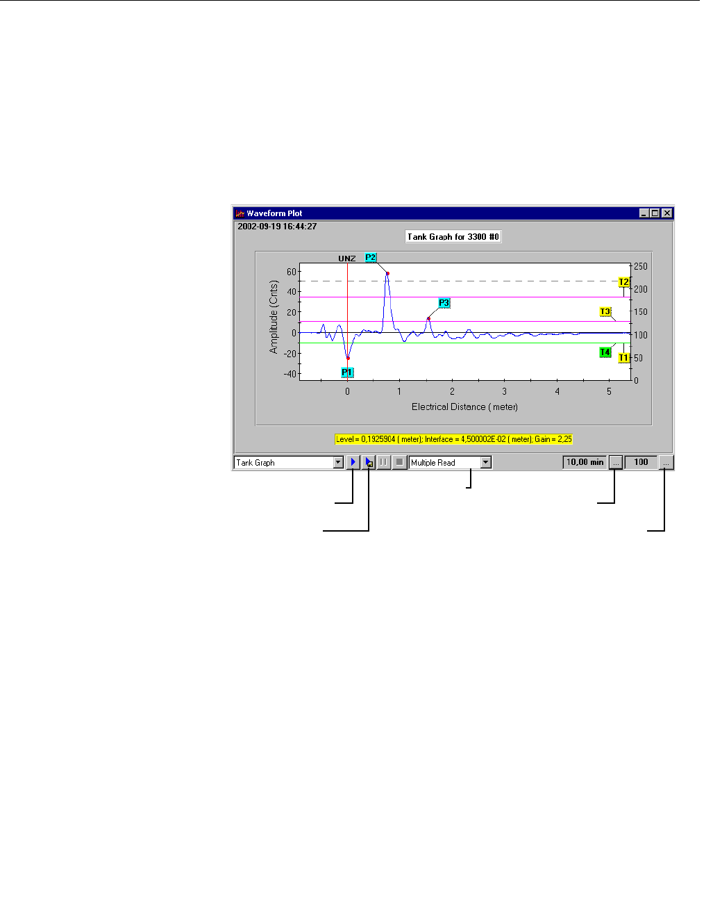
Reference Manual
00809-XXXX-4811, Rev AA
February 2012
Rosemount 3308
7-4
PRELIMINARY
Normally the thresholds are adjusted to approximately 50% of the signal peak
amplitude. To adjust the Amplitude Thresholds open the Advanced section
in the RCT Project Bar and choose Device Commands>Details>Set Nominal
Thresholds. To reset the default values set Amplitude Threshold=0 (zero).
Logging and saving to disk
The Waveform plot can be automatically logged and saved to file by
specifying the read plot interval and the number of plots to log.
Figure 7-3. Disk logging
Waveform plot
The Read Plot Interval entry field specifies the time interval between plots
that are saved to disk. For example, type 10 if you want the waveform plot to
be updated every ten minutes.
Number of plots to log specifies the maximum number of plot files that will
be stored. The default value is 100.
Click the Start Disk Logging button to start the log. Make sure that Read
Action type is set to Multiple Read. Otherwise RCT will only save one log file.
Choose a destination folder and enter a file name. For each new file the
corresponding number is appended to the end of the file name.
Start disk logging
Start monitoring
Number of plots
Read plot interval
Read action type
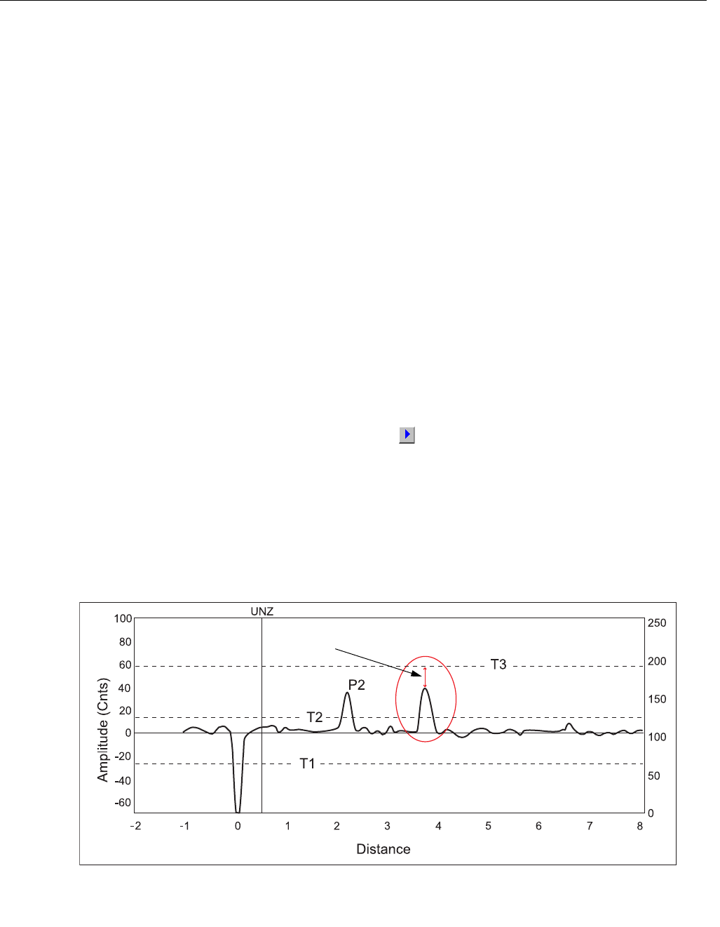
Reference Manual
00809-XXXX-4811, Rev AA
February 2012
7-5
Rosemount 3308
PRELIMINARY
Interface Measurements
for Semi-Transparent
Bottom Products
In interface applications where the bottom product has a low dielectric
constant, or if the signal is attenuated in the upper product, the amplitude of
the reflected signal is relatively low and difficult for the transmitter to detect. In
such a case it may be possible to detect the reflected signal if the
corresponding amplitude threshold is adjusted.
The Radar Configuration Tool (RCT) lets you view a waveform plot to analyze
the measurement signal. The plot shows the signal and the thresholds used
for the different amplitude peaks. By adjusting amplitude threshold T3 it is
possible to detect even weak interface signals.
Guidelines for amplitude threshold settings:
• The amplitude threshold T3 should be approximately 50 % of the
interface signal amplitude.
• Threshold T3 should not be less than 3.
• If possible, T3 should be higher than T2.
You can use the RCT software or a Field Communicator to change the
amplitude thresholds. For the Field Communicator use the HART command
[1, 4, 5, 3]. See also “Amplitude Threshold Settings” on page 7-12.
RCT lets you view a plot of the measurement signal along with the current
thresholds:
1. From the View menu choose the Plotting option, or double-click the
Plotting icon in the Advanced section of the RCT Project Bar.
2. Click the Read button .
3. To adjust the Amplitude Thresholds open the Advanced section in the
RCT Project Bar and choose Device Commands>Details>Set Nominal
Thresholds.
Figure 7-4. Waveform plot
indicating that the amplitude
threshold for the interface peak
is too high.
The amplitude threshold is above
the measurement signal peak
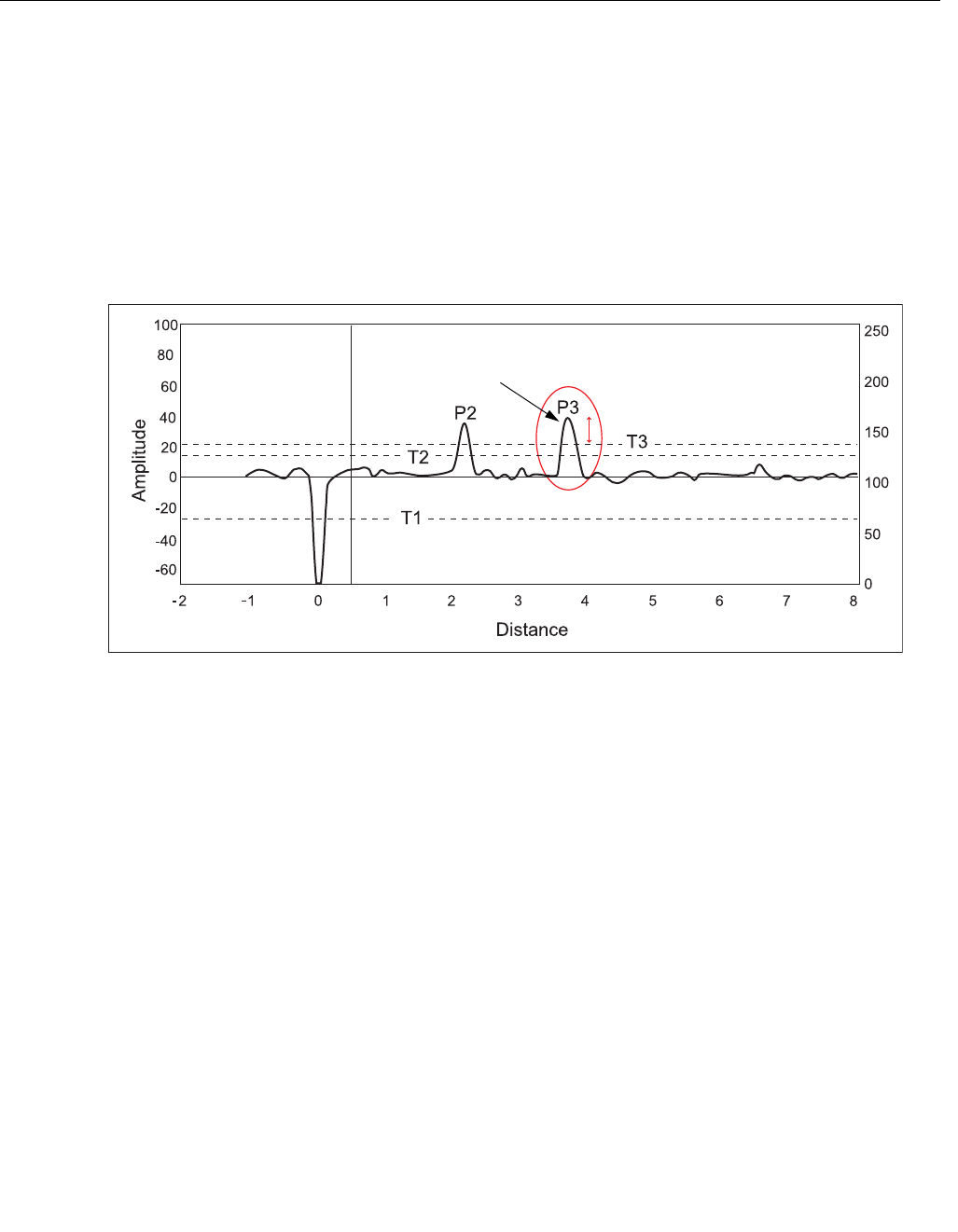
Reference Manual
00809-XXXX-4811, Rev AA
February 2012
Rosemount 3308
7-6
PRELIMINARY
Figure 7-4 illustrates a situation where amplitude threshold T3 is too high. The
signal amplitude peak at the interface between the upper and lower products
is not detected in this case. By adjusting amplitude threshold T3, the peak at
the interface between the upper and lower products is detected as illustrated
in Figure 7-5:
Figure 7-5. After changing the
amplitude threshold the
transmitter detects the interface
The amplitude threshold is
adjusted below the peak to allow
the interface peak to be detected
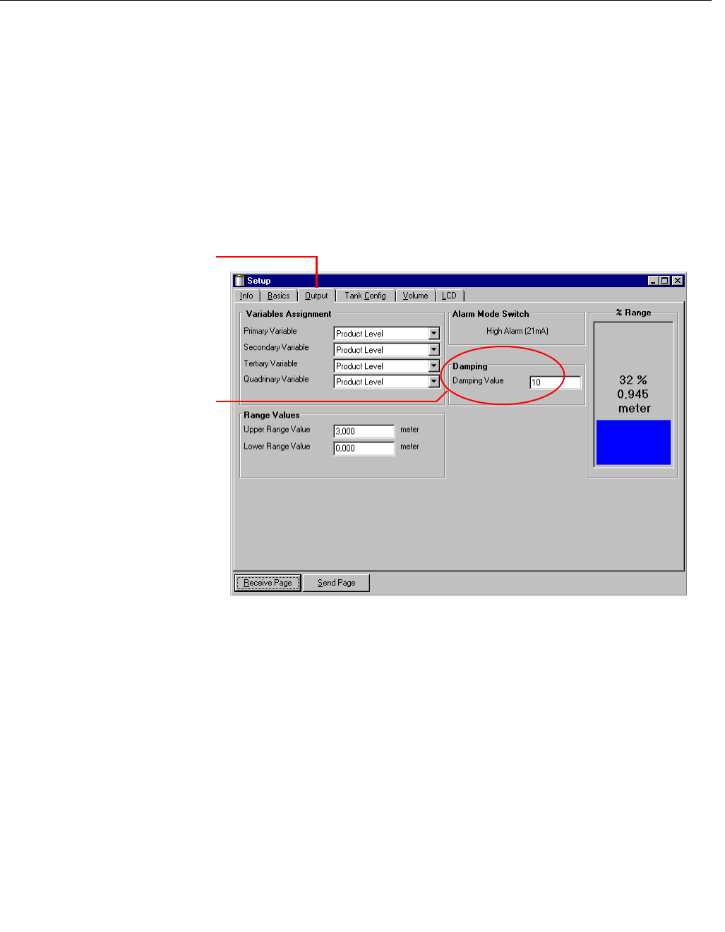
Reference Manual
00809-XXXX-4811, Rev AA
February 2012
7-7
Rosemount 3308
PRELIMINARY
High Level Rates The measurement signal is filtered in order to minimize the influence of
disturbing noise. In most measurement situations this does not have a
noticeable effect on the response time to level changes. If high level rates
occur it may however be necessary to reduce the damping value in order to
allow the transmitter to respond quicker. If there is too much noise the
damping value may be increased in order to get a stable measurement signal.
You can use the RCT software or a Field Communicator to change the
Damping value. For the HART Communicator use the key sequence
[1, 3, 5].
In the RCT software open the Setup>Output tab and enter the desired
Damping value:
The Damping parameter determines how quickly the transmitter responds to
level changes and how robust the measurement signal is against noise.
Technically, a damping value of 10 means that in 10 seconds the output from
the transmitter is about 63% of the new level value. Consequently, when there
are rapid level changes in the tank, it may be necessary to decrease the
Damping value for the transmitter to be able to track the surface. On the other
hand, in noisy environments, and if level rates are low, it may be better to
increase the damping value to have a stable output signal.
Damping
Output tab
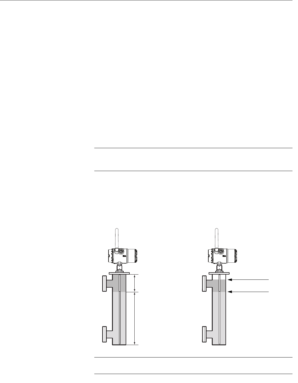
Reference Manual
00809-XXXX-4811, Rev AA
February 2012
Rosemount 3308
7-8
PRELIMINARY
Interface Measurements
with Fully Immersed
Probes
The Rosemount 3308 transmitter has a measurement option which makes it
possible to handle interface measurements when the product level is not
visible, for example in a full bridle pipe as illustrated in Figure 7-6. In this case
the probe is fully immersed into the upper product, and only the interface level
is detected by the transmitter. Even if the upper product level drops, it is
ignored by the transmitter which continues to measure only the interface level,
but the measurement accuracy is reduced since the transmitter does not take
into account the influence of the air gap above the product surface.
The Measurement Mode parameter is available via the
HART command [1, 3, 3, 4]. Choose the Interface when Immersed Probe
option.
Measurement mode Interface when Immersed Probe can also be activated in
the RCT software:
1. Open the Setup window.
2. Select the Tank Config tab.
3. Choose Measurement Mode Interface when Immersed Probe.
4. Click the Send Page button.
NOTE!
Do not use Measurement Mode Interface when Immersed Probe in “standard”
applications when both Interface Level and Product Level are measured.
If the product level drops, the air filled region in the upper part of the pipe will
slightly reduce the measurement accuracy of the interface level. To achieve
high accuracy in this measurement mode the probe must be fully immersed.
Figure 7-6. Interface Level
measurements in a full bridle
pipe.
NOTE!
Adjust Threshold T2 if the level pulse is not detected.
Interface Distance
Interface Level
Product Level
is ignored
Interface Level is
measured
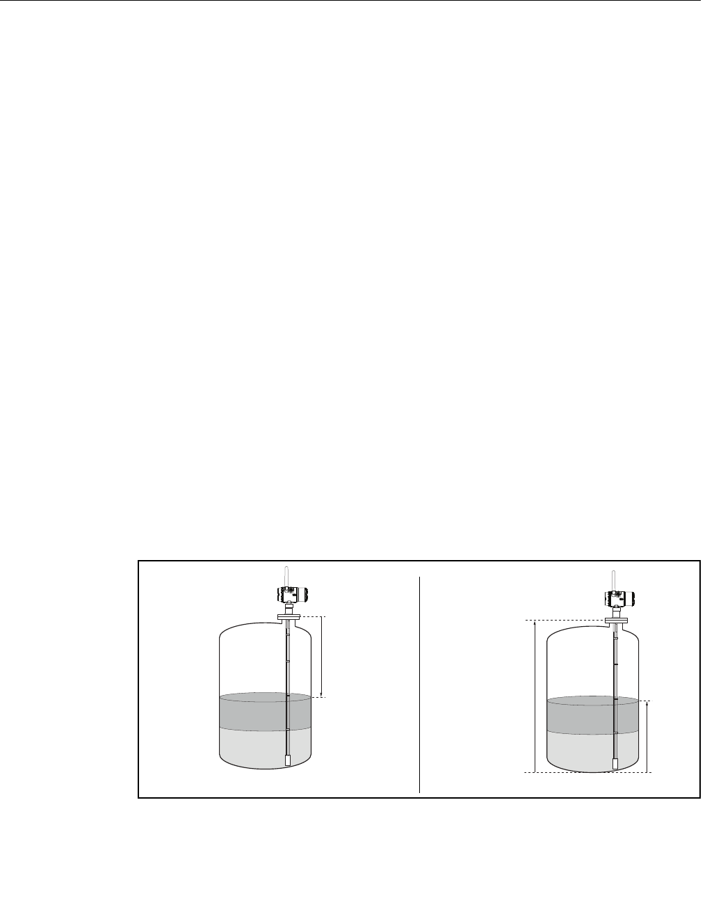
Reference Manual
00809-XXXX-4811, Rev AA
February 2012
7-9
Rosemount 3308
PRELIMINARY
SERVICE
Level and Distance
Calibration When calibrating the transmitter it is important that the product surface is calm
and that the tank is not being filled or emptied.
A complete calibration is performed in two steps:
1. Calibrate the Distance measurement by adjusting the Calibration Offset
parameter.
2. Calibrate the Level measurement by adjusting the Tank Height.
Distance calibration
1. Measure the actual distance between the Upper Reference Point and the
product surface.
2. Adjust the Calibration Offset so that the Distance measured by the
transmitter corresponds to the actual distance.
The Calibration Offset parameter is available via
HART command [1, 4, 5, 5],
or
RCT: open the Advanced section in the Project Bar and choose Device
Commands>Basics>Set Calibration Offset.
Level calibration
1. Measure the actual Product Level.
2. Adjust the Tank Height so that the measured Product Level corresponds
with the actual level.
Figure 7-7. Distance and Level
calibration
Level
Reference Point
Tank Height
Distance
Reference Point

Reference Manual
00809-XXXX-4811, Rev AA
February 2012
Rosemount 3308
7-10
PRELIMINARY
Disturbances at the Top
of the Tank Using the Trim Near Zone Function
For transmitters using the Guided Wave Radar technology the performance In
the Near Zone (referred to as the region between 0-1.6 ft (0-0.5 m) below the
Upper Reference Point) is normally somewhat limited. However, the
Rosemount 3308 transmitter is equipped with software functionality that
minimizes the Upper Transition Zone. The factory setting is normally sufficient
and doesn’t need to be repeated after installation.
However, since the setting is optimized depending on actual installation,
further trimming may be necessary in the case of unfavorable conditions. This
may for example be the case if a Single Lead probe is mounted in a small
nozzle, or if there are disturbing obstacles in the Near Zone. The trimming
means that the measurement performance in the Near Zone is maintained
even under these conditions and prevents false echo indication.
To trim the Near Zone performance do the following:
1. Make sure that the product level is below the Near Zone region
(0-1.6 ft (0-0.5 m) below the Upper Reference Point).
2. Start the Radar Configuration Tools (RCT).
3. Choose the Device Commands option from the View menu.
4. Open the Details folder.
5. Click the Trim Near Zone option.
6. Select the Update option and click the OK button.
NOTE!
The Trim Near Zone function should only be used for reducing impact from
constant disturbances. It is not suitable for occasional disturbances.
To reset the transmitter to factory settings do the following:
1. Start the Radar Configuration Tools (RCT).
2. Choose the Device Commands option from the View menu.
3. Open the Details folder.
4. Click the Trim Near Zone option.
5. Select the Reset to Factory Settings option and click the OK button.
Changing the Upper Null Zone
Measurements are not performed within the Upper Null Zone (UNZ). By
setting the UNZ parameter to zero, measurements can be performed in the
region close to the flange (Near Zone). However, it is very important that there
are no disturbances in that region if UNZ is set to zero.
If there are measurement problems in the upper part of the tank you may use
the Trim Near Zone function as described above.
If the desired measurement range is below the Near Zone, or if disturbing
objects are located below the Near Zone, the Upper Null Zone parameter can
be used to avoid measurements above a certain level.
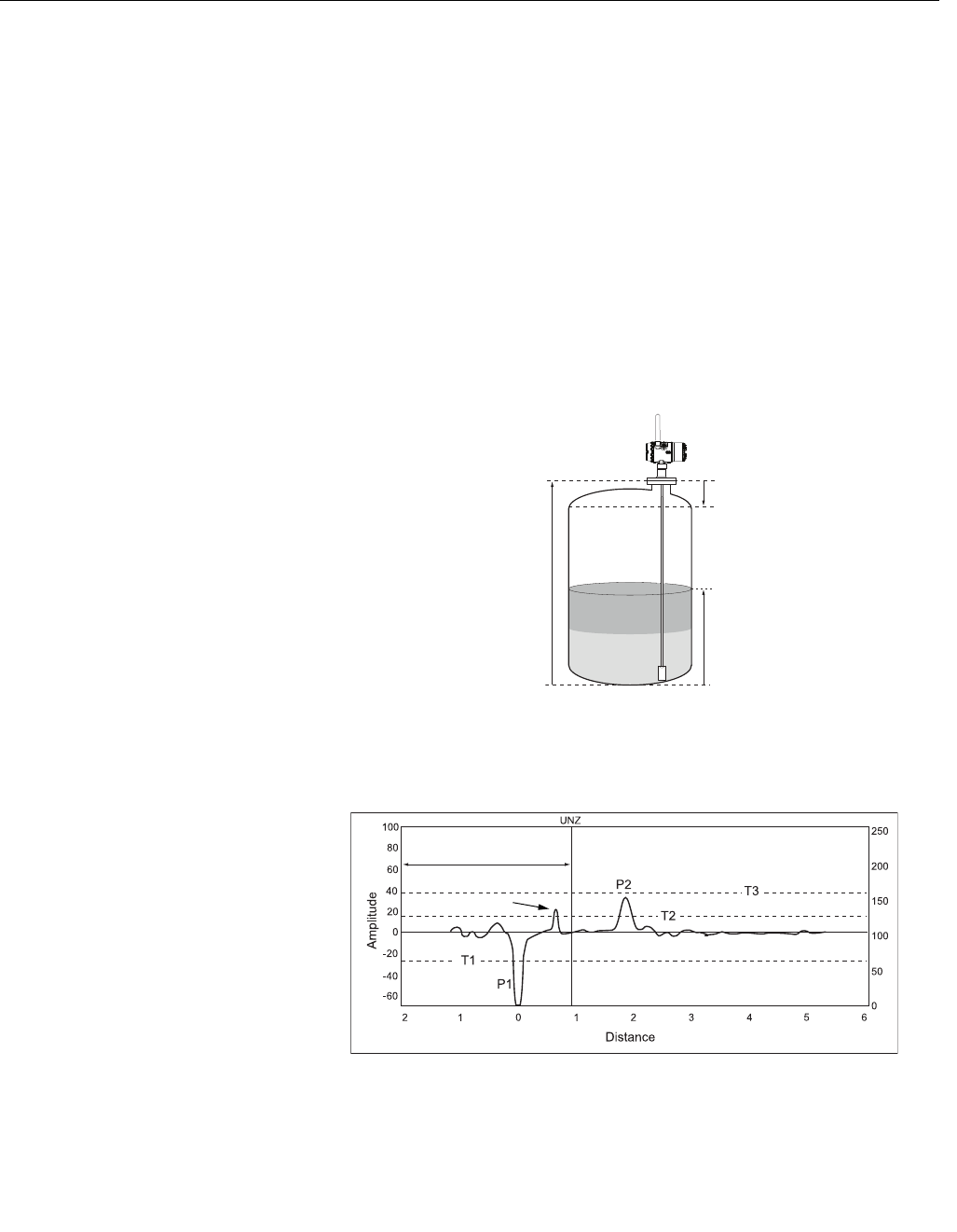
Reference Manual
00809-XXXX-4811, Rev AA
February 2012
7-11
Rosemount 3308
PRELIMINARY
To set the Upper Null Zone do one of the following:
1. Select the HART command [1, 3, 3, 1].
2. Enter the desired value,
or
1. Start the Radar Configuration Tool (RCT).
2. Click the Setup icon in the RCT workspace Project Bar.
3. Choose the Tank Config tab in the Setup window.
4. Click the Receive Page button.
5. Type the desired value in the Upper Null Zone field.
6. Click the Send Page button. Now the Upper Null Zone is stored in the
transmitter memory.
Figure 7-8. Upper Null Zone
Figure 7-9. Identifying the Upper
Null Zone in the RCT Waveform
Plot
Tank Height
Upper Null
Zone
Product Level
Upper Reference Point
--
Upper Null Zone
Disturbance
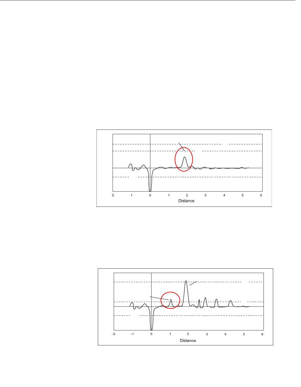
Reference Manual
00809-XXXX-4811, Rev AA
February 2012
Rosemount 3308
7-12
PRELIMINARY
Amplitude Threshold
Settings The amplitude thresholds are automatically adjusted to appropriate values in
order to filter out noise and other non-valid measurements from the
measurement signal.
The amplitude of the measurement signal, i.e. the amplitude of the signal that
is reflected by the product surface, is related to the actual dielectric constant
of the product. The amplitude threshold that is used by the transmitter is
based on the parameter configuration of the current product dielectric
constant (see Section 5: Basic Configuration). Normally no other threshold
adjustment is needed, but if the transmitter still does not track the product
surface correctly it may be necessary to adjust the threshold values.
The Radar Configuration Tool (RCT) has a plot function allowing you to view
the reflections along the probe.
If the amplitude threshold is too high the product level is not detected as
illustrated in Figure 7-10.
Figure 7-10. Example 1:
amplitude threshold T2 is too
high.
If there are disturbing objects in the tank the threshold must be carefully set in
order to avoid locking on the wrong amplitude peak. In Figure 7-11 the
transmitter has locked on a peak above the actual product surface, i.e. a
disturbance was interpreted as the product surface, whereas the actual
product surface was interpreted as an interface or the probe end.
Figure 7-11. Example 2:
amplitude threshold T2 is too
low.
P1
T1
T2
T3
Amplitude
100
80
60
-60
40
-40
20
-20
0100
50
0
150
200
250
-
-
T2 is above the
Level peak
P1
P2
P3
T1
T2
T3
Amplitude
100
80
60
-60
40
-40
20
-20
0100
50
0
150
200
250
Actual surface
Disturbing echo
misinterpreted as
product surface
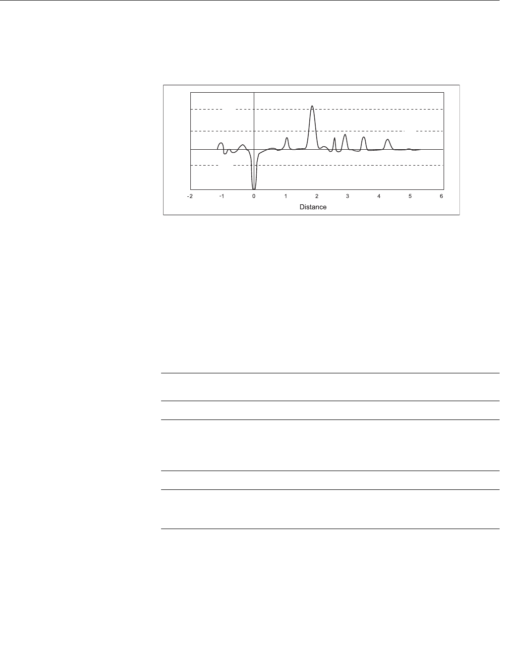
Reference Manual
00809-XXXX-4811, Rev AA
February 2012
7-13
Rosemount 3308
PRELIMINARY
By adjusting the amplitude threshold T2 the product surface is detected
correctly as illustrated in Figure 7-12.
Figure 7-12. Waveform plot after
threshold T2 was adjusted
To adjust the amplitude thresholds select HART command [1, 4, 5, 3]
or
1. Start the Radar Configuration Tool (RCT).
2. Choose the Device Commands option from the View menu.
3. Open the Details folder.
4. Click the Set Nominal Thresholds option.
The thresholds T2 and T3 should be set to about 50% of the measured signal
amplitude for the product surface and the interface peaks, respectively.
NOTE
Amplitude thresholds should not be set to values less than 3.
NOTE
Check that the dielectric constant parameter setting is reasonably close to the
actual dielectric constant value of the upper product before changing the
amplitude thresholds.
NOTE
Default Amplitude thresholds can be set by typing 0 as the new threshold
value.
P1
P2
T1
T2
T3
Amplitude
100
80
60
-60
40
-40
20
-20
0100
50
0
150
200
250
After T2 is adjusted the product
surface is correctly detected
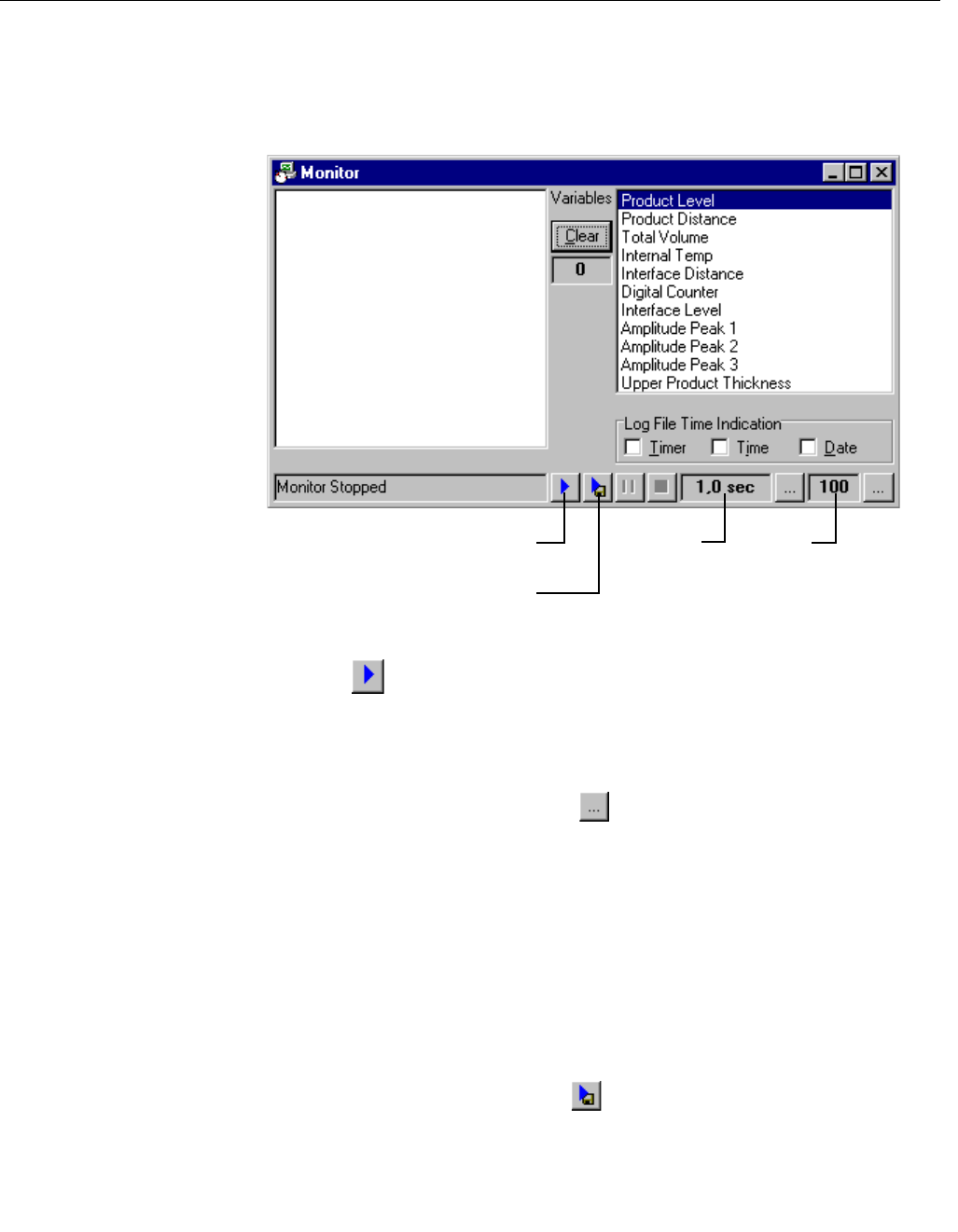
Reference Manual
00809-XXXX-4811, Rev AA
February 2012
Rosemount 3308
7-14
PRELIMINARY
Logging Measurement
Data To start logging do the following:
1. Click the Monitor icon in the RCT workspace or choose the Monitor
option from the View menu.
2. Choose the desired variables to be monitored and click the Start Monitor
button.
Saving the log to disk
1. Choose the desired variables to be monitored.
2. Click the Log interval button and enter a time interval. For example,
type 10 if you want data to be logged every tenth second.
3. Click the Counter button and enter the maximum number of files to be
stored. The Counter is used to limit the amount of data stored on the
hard disk. Each time the maximum number of entries in a log file is
reached, the current log file is saved and a new file is created. This
procedure continues up to the maximum number of files given by the
Counter value. The file size is limited to 60,000 entries which can easily
be handled by spreadsheet programs like MS Excel.
4. Select the desired options for Timer, Time and Date. By selecting a
check box the corresponding time indication is stored for each log entry
in the log file.
5. Click the Start disk logging button.
6. Choose a destination folder and enter a file name.
Start disk logging
Start monitoring CounterLog interval
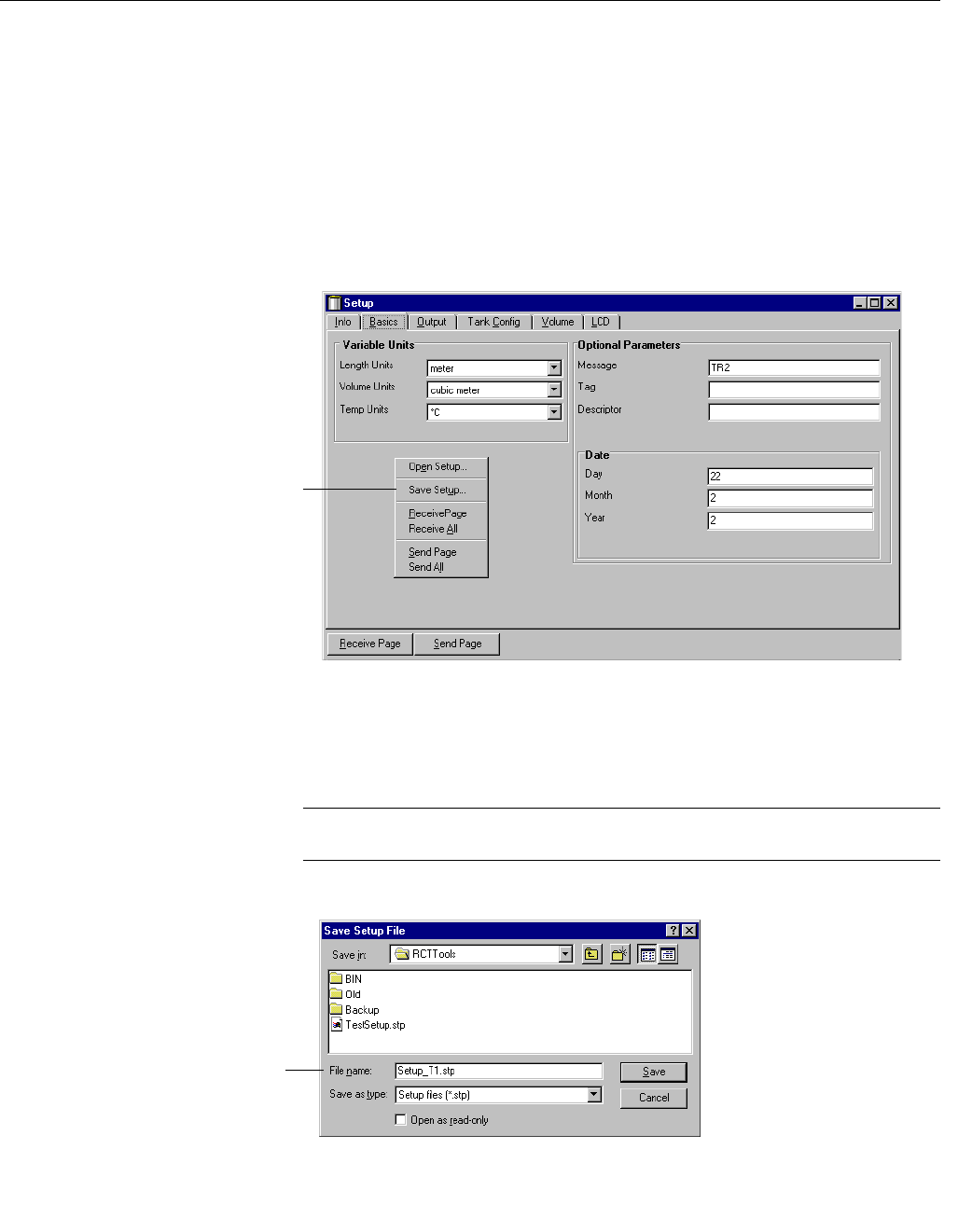
Reference Manual
00809-XXXX-4811, Rev AA
February 2012
7-15
Rosemount 3308
PRELIMINARY
Saving the Transmitter
Configuration The Radar Configuration Tool offers different methods to save the current
transmitter configuration:
• Save only the configuration specified in the Setup window.
• Use the more extensive function in the Memory Map window.
You can use a stored configuration file as a backup of the current
configuration, or it can be distributed for service purposes.
To save the current transmitter setup do the following:
1. Click the Setup icon in the RCT workspace or choose the Setup option
from the View menu to open the Setup window.
2. Click the right mouse button and choose the Receive All option,
or
from the Setup menu choose the Receive All option.
Alternatively, you can use the Receive Page option on each individual
page.
NOTE!
All pages must be received before the setup can be saved.
3. Click the right mouse button and choose the Save Setup option.
4. Choose a destination folder and enter a file name.
5. Click the Save button.
Save Setup
File name
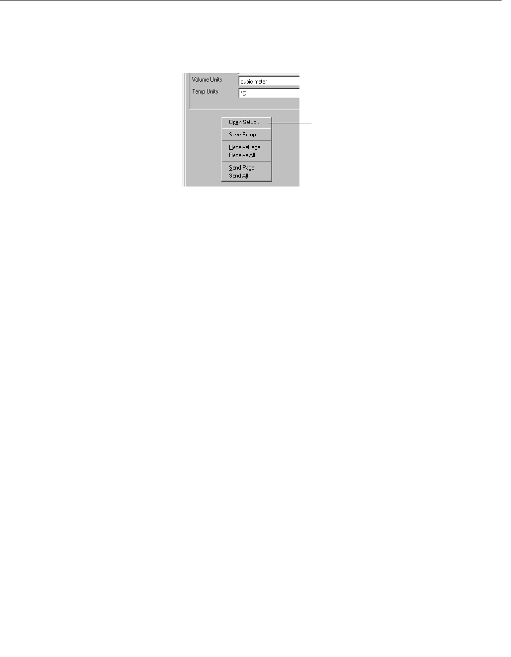
Reference Manual
00809-XXXX-4811, Rev AA
February 2012
Rosemount 3308
7-16
PRELIMINARY
To load a setup
1. Click the Setup icon in the RCT workspace or choose the Setup option
from the File menu.
2. In the Setup window click the right mouse button and choose the Open
Setup option, or
from the File menu choose the Open Setup option.
3. Open the source folder and select the desired setup file.
4. Click the Open button.
Memory Map
The Memory Map window lets you view the current transmitter database
registers. It is also possible to save the current database for backup or service
purposes, and it is also possible to download a backup database to the
transmitter. To save configuration data in the Memory Map window:
1. Start the RCT program.
2. Choose the View>Memory option, or click the Memory Map icon in the
RCT workspace (Advanced section at the left side of the workspace
window).
3. Choose the All EE option from the drop-down list.
4. Click the Receive button. (It may take a few minutes to read the
database).
5. Click the right mouse button and choose the Save Memory As option.
6. Type the desired file name and click the OK button. Now the current
database is stored.
See the Online Help in RCT for further information on how to open a saved
database and how to download a database to the transmitter.
Open Setup
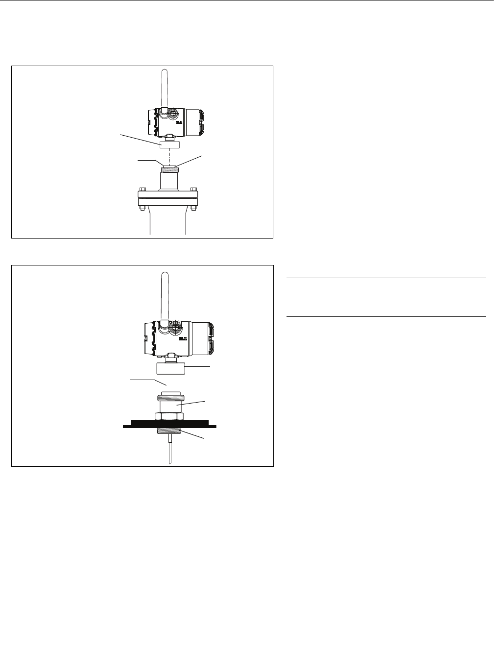
Reference Manual
00809-XXXX-4811, Rev AA
February 2012
7-17
Rosemount 3308
PRELIMINARY
Removing the
Transmitter Head
1. Loosen the nut that connects the
transmitter housing to the Process Seal.
2. Carefully lift the transmitter head.
3. Make sure that the upper surface of the
Process Seal is clean and the
spring-loaded pin at the center of the
Process Seal is properly inserted (the pin
should move back when pushed into the
hole).
4. Attach the protection plug to the Process
Seal.
Nut
Process Seal
Put the protection
plug here!
FLANGE VERSION
NOTE
Do not remove the Process Seal from the
adapter!
Nut
Process Seal
Adapter
THREADED VERSION
Put the protection
plug here!
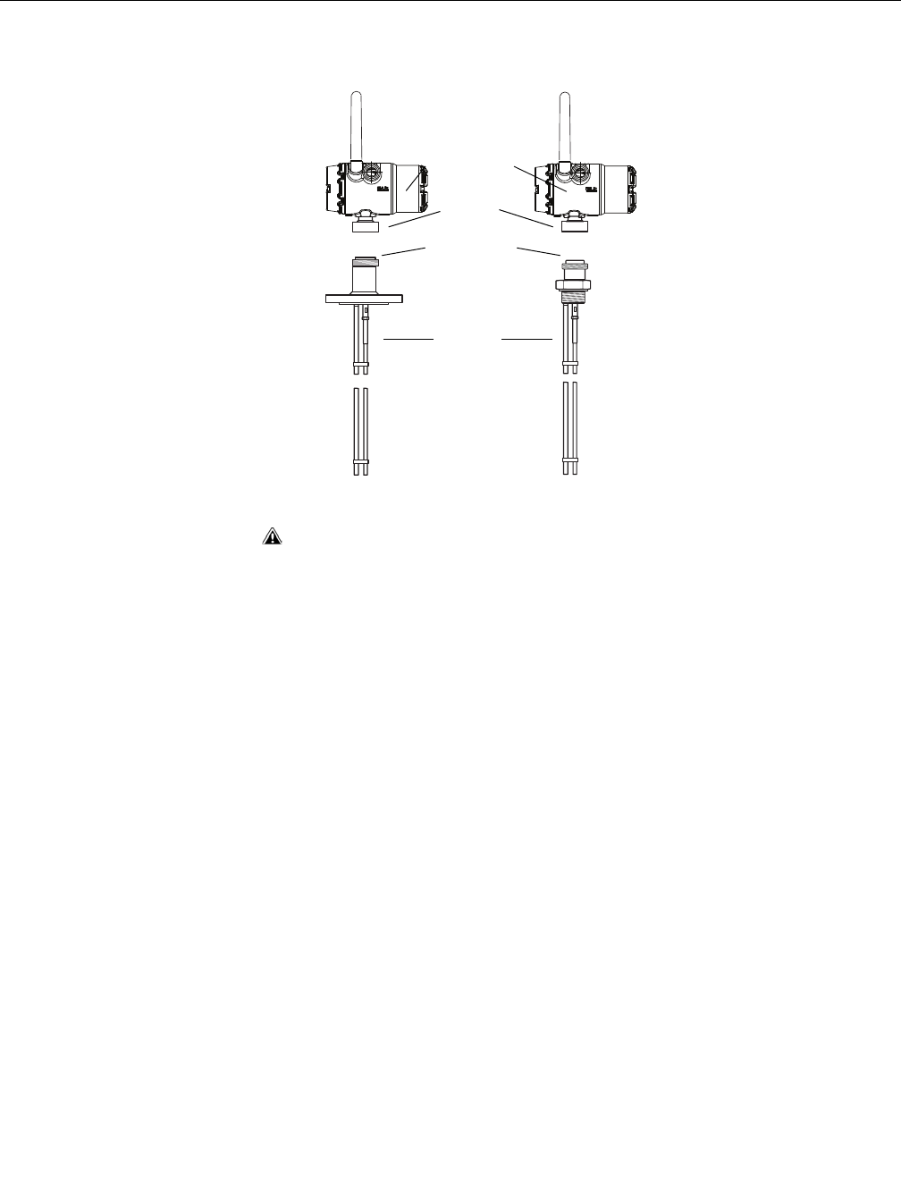
Reference Manual
00809-XXXX-4811, Rev AA
February 2012
Rosemount 3308
7-18
PRELIMINARY
Changing the Probe
1. Loosen the nut.
2. Remove the transmitter head from the old probe.
3. On the new probe, make sure that the protection plug is removed and the
upper surface of the Process Seal is clean. Also make sure that the
spring-loaded pin at the center of the Process Seal is properly inserted.
4. Mount the transmitter head on the new probe.
5. Fasten the nut again.
6. If the new probe is not of the same type as the old one, update the
transmitter configuration by setting the Probe Type parameter to the
appropriate value:
HART Fast Key sequence [1, 3, 2, 3],
or
RCT Setup/Tank Config.
7. Measure the probe length and enter the measured value:
HART Fast Key sequence [1, 3, 2, 2],
or
RCT Setup/Tank Config.
8. Verify that the transmitter is calibrated.
Nut
Probe
Transmitter
head
Process
Seal

Reference Manual
00809-XXXX-4811, Rev AA
February 2012
7-19
Rosemount 3308
PRELIMINARY
DIAGNOSTIC
MESSAGES
Troubleshooting If there is a malfunction despite the absence of diagnostic messages, see
Table 7-1 for information on possible causes.
Table 7-1. Troubleshooting
chart
Table 7-2. Maintenance and Troubleshooting Suggestions
Symptom Possible cause Action
Both P2 and P3 are detected but Interface
Level is reported as Not A Number (NAN)
in the waveform plot.
Measurement Mode is set to “Level Only”. Set Measurement Mode to “Level and
Interface” (see “Basic Configuration” on
page 5-9).
Both Level and Interface Level are
reported as NAN.
Probe is not connected. Use the command “Read Gauge Status”
and check if error “Probe Failure” is
active. If this is the case, check the probe
connection.
Both P2 and P3 are detected but the
interface level is equal to the product
Level.
• P3 is identified as a double bounce.
• P2 and P3 are very close.
Adjust thresholds T2 and T3, see
“Amplitude Threshold Settings” on
page 7-12 for more information.
P2 is detected but Level is incorrectly
reported as Full or Empty.
Use the command “Read Gauge Status”
and check if the warning “Probe
Immersed” is active. If this is the case
check that:
• the transmitter is configured with
correct probe type,
• the reference pulse (P1) is below
amplitude threshold T4. If not, adjust
T4 to an appropriate value.
The reference pulse is not detected. • The tank is full.
• The transmitter is configured with
wrong probe type.
• Amplitude Threshold T1 is not correct.
• Check the product level.
• Check that correct probe type is
configured.
• Check Amplitude Threshold T1.
Level accuracy seems off. • Configuration error. • Check the Tank Height parameter.
• Check status information and
diagnostic information.
Integral display does not work. • Check the display configuration.
• Check Display connection.
Symptom Corrective Actions
Wireless Troubleshooting
Poor wireless connectivity 1. Verify device oriented for optimal connections (See Section 2: Transmitter Overview
of this document)
2. Verify wireless network best practices are followed (See Appendix C for more
information)
Acoustic Transmitter not joining network 1. Verify the device has power
2. Verify the device is within effective communications range
3. Verify the proper Network ID has been entered into the device
4. See troubleshooting section of the Smart Wireless Gateway for more information
(Document No. 00808-0200-4420)
Limited Bandwidth Error 1. Use the slowest acceptable update Rate
2. Increase communication paths by adding more wireless points
3. Check that the device has been online for at least an hour
4. Create a new network with an additional Smart Wireless Gateway
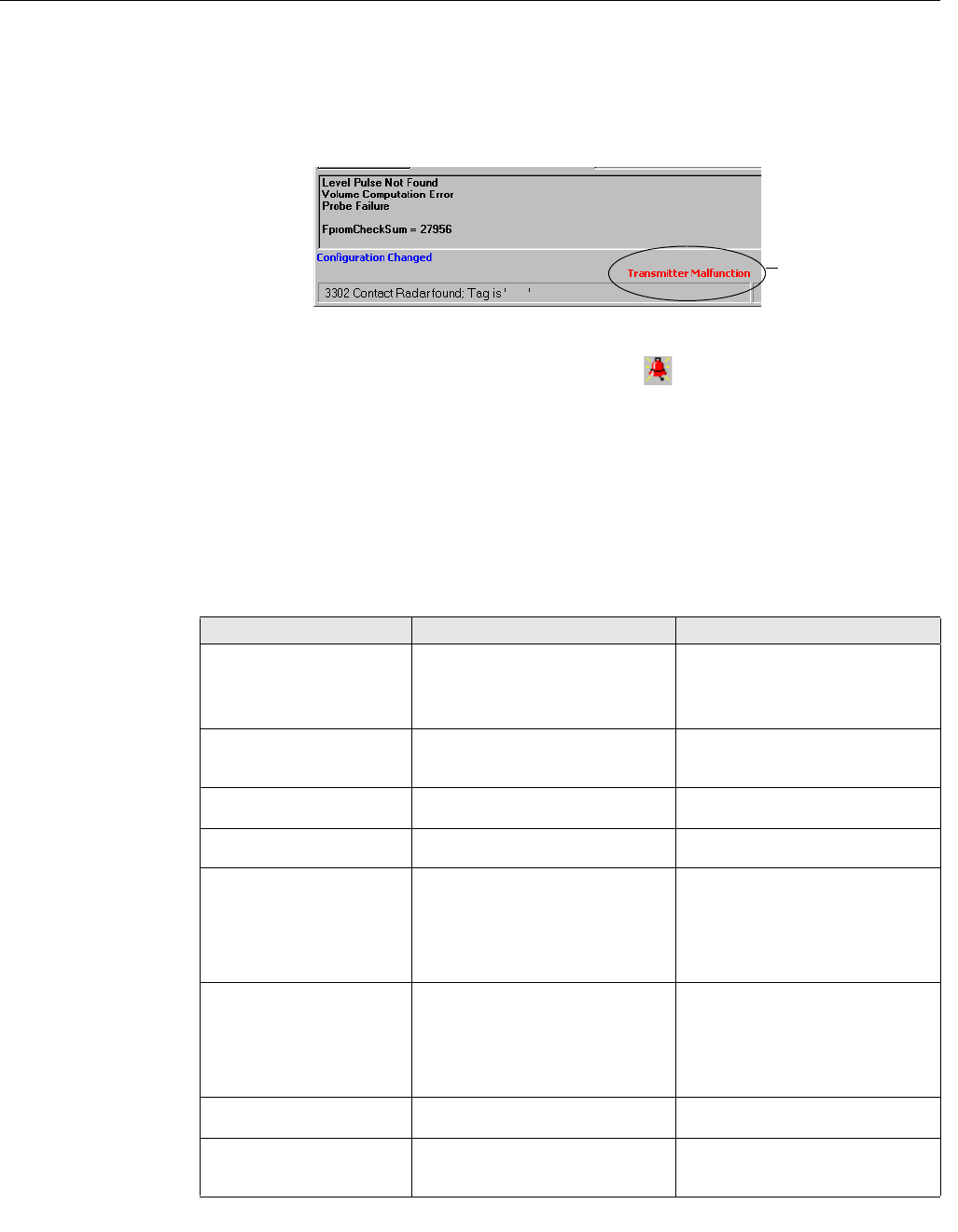
Reference Manual
00809-XXXX-4811, Rev AA
February 2012
Rosemount 3308
7-20
PRELIMINARY
Errors Table 7-3 is a list of diagnostic messages that may be displayed on the
Integral Display, on the Field Communicator, in AMS Suite or by the Radar
Configuration Tools (RCT) software. Errors normally result in Analog Output
alarm.
Errors are indicated in RCT by the message “Transmitter malfunction”:
To see the error message do one of the following:
• Click the Read Gauge Status icon in the toolbar at the top of the
RCT workspace.
• 1. Open the Advanced section in the RCT workspace Project Bar and
click the Device Commands icon,
or
choose the Device Commands option from the View menu.
2. Open the folder named Diag and double-click the Read Gauge
Status option.
Table 7-3. Error messages.
Error indication
Message Description Action
Invalid configuration.
LCD error code: CNFIG.
At least one configuration parameter
is outside allowed range.
NOTE: the default values are used
until the problem is solved.
• Load default database and restart
the transmitter.
• Contact Emerson customer service
if the problem persists.
RAM failure was detected
during startup test.
LCD error code: 00001.
The transmitter performs an
immediate reset.
Contact Rosemount service
department.
FPROM failure was detected
during startup test.
The transmitter performs an
immediate reset.
Contact Rosemount service
department.
Waveform acquisition failure.
LCD error code: 00006.
This error is probably caused by
hardware failure.
Contact Rosemount service
department.
EEPROM factory checksum.
LCD error code: 00007.
Checksum error in the factory
configuration parameters. Can be
caused by power failure during
configuration or by hardware error.
NOTE: the default values are used
until the problem is solved.
Contact Rosemount service
department.
EEprom user checksum error.
LCD error code: 00008.
Caused by error in the User
Configuration parameters. Can be
caused by power failure during
configuration or by hardware error.
NOTE: the default values are used
until the problem is solved
• Load default database and restart
the transmitter.
• Contact Emerson customer service
if the problem persists.
Software error.
LCD error code: 00010.
Contact Rosemount service
department.
Probe failure.
LCD error code: 00013.
Probe is not detected. Check that the probe is correctly
mounted (see “Changing the Probe”
on page 7-18).

Reference Manual
00809-XXXX-4811, Rev AA
February 2012
7-21
Rosemount 3308
PRELIMINARY
Warnings Table 7-4 is a list of diagnostic messages that may be displayed on the
Integral Display, on the Field Communicator or by the Radar Configuration
Tools (RCT) software. Warnings are less serious than errors and in most
cases do not result in Analog Output alarms.
Warnings are indicated by a message at the bottom of the RCT workspace. To
see the warning message do one of the following:
• Click the Read Gauge Status icon in the toolbar at the top of the
RCT workspace.
• 1. Open the Advanced section in the RCT workspace Project Bar and
click the Device Commands icon,
or
choose the Device Commands option from the View menu.
2. Open the folder named Diag and double-click the Read Gauge
Status option.
Table 7-4. Warning messages.
Message Description Action
Reference pulse not
found.
Possible cause:
• Reference pulse immersed in
high dielectric liquid.
• Wrong threshold level T1.
• Hardware error.
• View the waveform plot and check
amplitude threshold T1.
• Check that the tank is not overfull.
No level pulse is
found.
Possible cause:
• Wrong threshold level T2.
• Liquid level in Transition Zone or
below probe end.
• View the waveform plot and
check amplitude threshold T2.
Interface pulse not
found.
Possible cause:
• Wrong threshold level T3.
• Interface level too close to the
upper product level.
• No level pulse detected.
• View the waveform plot and
check amplitude threshold T3.
Internal temperature
out of range.
-40 ºC<Internal Temperature<85 ºC. Contact Rosemount service
department.
Volume computation
warning. • Volume configuration error.
• Strapping table error.
• Check that correct tank type is
selected for volume configuration.
• Check that tank dimensions for
volume are correct.
• If strapping table is used, check the
level vs. volume points.
Immersed probe. • Wrong threshold level T4.
• Reference pulse immersed in
liquid.
• View the waveform plot and check
amplitude threshold T4.

Reference Manual
00809-XXXX-4811, Rev AA
February 2012
Rosemount 3308
7-22
PRELIMINARY

Reference Manual
00809-XXXX-4811, Rev AA
February 2012 Rosemount 3308
www.rosemount.com
PRELIMINARY
Appendix A Reference Data
Functional Specification . . . . . . . . . . . . . . . . . . . . . . . . . . . . .page A-2
Performance Specification . . . . . . . . . . . . . . . . . . . . . . . . . . . page A-5
Physical Specification . . . . . . . . . . . . . . . . . . . . . . . . . . . . . . . page A-8
Dimensional Drawings . . . . . . . . . . . . . . . . . . . . . . . . . . . . . . .page A-13
Ordering Information . . . . . . . . . . . . . . . . . . . . . . . . . . . . . . . . page A-14

Reference Manual
00809-XXXX-4811, Rev AA
February 2012
Rosemount 3308
A-2
PRELIMINARY
FUNCTIONAL SPECIFICATION
General
Field of Application Liquids and semi-liquids level or liquid/liquid interfaces
Measurement Principle Time Domain Reflectometry (TDR).
(See Figure 2-1 on page 2-3 for a description of how it works)
Microwave Output Power
Telecommunication
(FCC and R&TTE)
Humidity 0 to 100% relative humidity
Start-up time
Wireless
Sensor Input Add types of sensor inputs.
Output IEC 62591 (WirelessHART) 2.4 GHz DSSS
Radio Frequency Power
Output from Antenna External (WK option) antenna: Maximum of 10 mW (10 dBm) EIRP Extended Range, External (WM option)
antenna: Maximum of 18 mW (12.5 dBm) EIRP
Humidity Limits 0-100% relative humidity
Wireless Update Rate User selectable, X sec. to 60 min.
IS Electrical Parameters
Display and Configuration
Integral Display The optional integral LCD can display discrete state and diagnostic information. Display updates at each
wireless update
Remote Display Data can be read remotely by using the four-digit Rosemount 751 Field Signal Indicator. For further
information, see the Rosemount 751 Product Data Sheet (Document Number 00813-0100-4378)
Configuration Tools
(See earlier “Output” diagrams)
Emerson Field Communicator (e.g. 375/475 Field Communicator),
Radar Configuration Tools (RCT) software package for PC (included with delivery of transmitter), or
Emerson AMS™ Device Manager for PC (visit www.emersonprocess.com/AMS for further information), or
or DeltaV or any other DD (Device Description) compatible host systems
Notes:
• DTM (compliant with version 1.2 of the FDT/DTM specification) is also available supporting
configuration in for instance Yokogawa Fieldmate/PRM, E+H™ FieldCare, and PactWare™
•
To communicate using RCT or AMS Device Manager, a HART modem is required. The HART
modem is
available as an RS232 or USB version (see “Accessories Rosemount 3308” on page A-20)
• The transmitter can be pre-configured by selecting Options code C1 (page page A-18) and sending a
completed Configuration Data Sheet (CDS). The CDS is available from www.rosemount.com
Output Units For Level, Interface, and Distance: ft, inch, m, cm, or mm
For Volume: ft3, inch3, Gallons, Imp gals, barrels, m3, or liters
Output Variables
Temperature Limits
Ambient Temperature The maximum and minimum ambient temperature for the electronics depends on the process temperature
and on the approval (see “Product Certifications” on page B-1).
• The temperature range for the optional Integral Display is –40 °F (–40 °C) to 185 °F (85 °C)
• To lower the temperature around the electronics, a Remote Mounting Connection can be used. The
maximum temperature for the Remote Housing Connection at the vessel connection point is
302 °F (150 °C).
Temperature Limits Verify that the operating atmosphere of the transmitter is consistent with the appropriate hazardous
locations certifications.
Storage Temperature –40 to 176 °F (–40 to 80 °C)
Operating Limit Storage Limit
With LCD Display -4 to 175 °F
(-20 to 80° C)
-40 to 185 °F
(-40 to 85 °C)
Without LCD Display -40 to 185 °F
(-40 to 85° C)
-40 to 185 °F
(-40 to 85 °C)
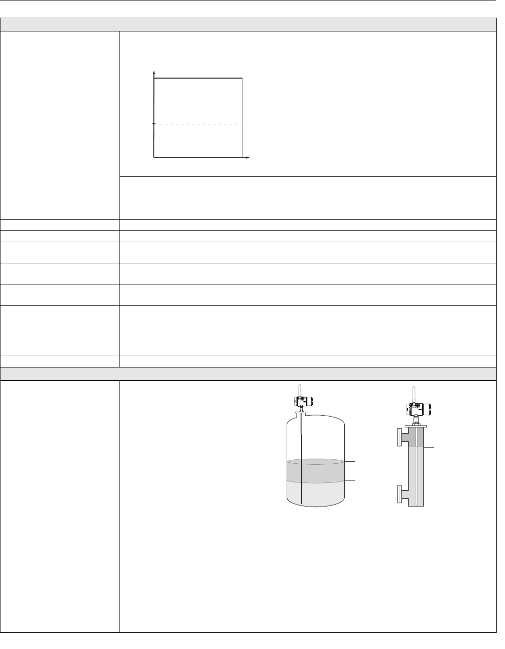
Reference Manual
00809-XXXX-4811, Rev AA
February 2012
A-3
Rosemount 3308
PRELIMINARY
Process Temperature and Pressure Rating
Process Temperature
Final rating depends on flange and O-ring
selection. Table A-1 on page A-4 gives
the temperature ranges for standard tank
seals with different O-ring materials.
Notes:
• The maximum product temperature is at the lower part of the flange
• The maximum temperature for the Remote Housing Connection at the vessel connection point is
302 °F(150 °C)
ASME / ANSI Flange Rating 316L SST Flanges according to ASME B16.5 Table 2-2.3. Max. 302 °F/580 psig (150 °C/40 bar)
EN Flange Rating
1.4404 according to EN 1092-1 material group 13E0. Max. 302 °F/580 psig (150 °C/40 bar)
Fisher & Masoneilan
Flange Rating 316L SST Flanges according to ASME B16.5 Table 2-2.3. Max. 302 °F/580 psig (150 °C/40 bar)
JIS Flange Rating 316L SST Flanges according to JIS B2220 material group 2.3. Max. 302 °F/580 psig (150 °C/40 bar)
Tri-Clamps Rating Maximum pressure is 16 bar for 1.5 in. (37.5 mm) and 2 in. (50 mm) housing; and 10 bar for 3 in. (75 mm)
and 4 in. (100 mm) housing. The final rating depends on the clamp and gasket.
Plate Design Certain models of flanged Alloy and PTFE covered probes have a tank connection design with a protective
flange plate of the same material as the probe and with a backing flange in 316L / EN 1.4404. The
protective flange plate prevents the backing flange from being exposed to the tank atmosphere
For Alloy C-276 and Alloy 400, probes with flange plate design is available up to Class 300/PN 40.
For PTFE, probes with flange plate design is available up to Class 150/PN 16
Flange Connection Rating See Table A-2 for the conditions used for flange strength calculations
Interface Measurements
Considerations The Rosemount 3308 is a good choice
for measuring the interface of oil and
water, or other liquids with significant
dielectric differences. It is also possible to
measure interfaces with a Rosemount
3308 in applications where the probe is
fully submerged in the liquid. If interface
is to be measured, follow these criteria:
• The dielectric constant of the upper
product must be known and should
not vary. The Radar Configuration
Tools software has a built-in dielectric
constant calculator to assist the user
in determining the dielectric constant
of the upper product
• The dielectric constant of the upper
product must have a lower dielectric
constant than the lower product to have a distinct reflection
• The difference between the dielectric constants for the two products must be larger than 10
• Max. dielectric constant for the upper product is 10 for the coaxial probe and 5 for twin lead probes
• The upper product thickness must be larger than 8 in. (0.2 m) for the flexible twin lead probe;
4 in. (0.1 m) for the rigid twin lead, and coaxial probes in order to distinguish the echoes of the two
liquids
• Sometimes there is an emulsion layer (mix of the products) between the two products which can affect
interface measurements. For guidelines on emulsion situations, consult your local Emerson Process
Management representative
Pressure
psig (bar)
Temperature °F (°C)
Max. Rating, Standard Tank Connections
580 (40)
232 (16)
-14 (-1)
-40 (-40) 302 (150)
PTFE covered probe
and flange (model
code 7)
Level
Interface Level
Level = Interface Level
Interface Measurement with
fully submerged probe
Interface Measurement

Reference Manual
00809-XXXX-4811, Rev AA
February 2012
Rosemount 3308
A-4
PRELIMINARY
Table A-1. Temperature ranges for standard tank seals with different O-ring materials
Tank seal with different
O-ring material Min. Temperature
°F (°C) in air Max. Temperature
°F (°C) in air
Fluoroelastomer (FKM) 5 (-15) 302 (150)
Ethylene Propylene (EPDM) -40 (-40) 266 (130)
Perfluoroelastomer (FFKM) 14 (-10) 302 (150)
Nitrile butadiene -31 (-35) 230 (110)
Table A-2. Conditions used for flange strength calculations
Bolting material Gasket Flange material Hub material
ASME / ANSI SST SA193 B8M
Class 2
Soft (1a) with min.
thickness 1.6 mm SST A182
Gr. F316L and
EN 10222-5-1.4404
SST SA479M 316L and
EN 10272-1.4404
EN, JIS EN 1515-1/-2 group
13E0, A4-70
Soft (EN 1514-1) with
min. thickness 1.6 mm
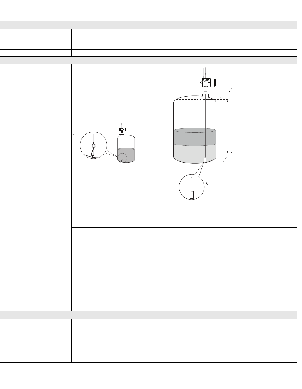
Reference Manual
00809-XXXX-4811, Rev AA
February 2012
A-5
Rosemount 3308
PRELIMINARY
PERFORMANCE SPECIFICATION
General
Reference Conditions Rigid Single Lead probe, 77 °F (25 °C) water
Reference Accuracy
Repeatability ± 0.04 in. (1 mm)
Ambient Temperature Effect Less than 0.01% of measured distance per °C
Measuring Range
Transition Zones These zones are areas where
measurements are non-linear or have
reduced accuracy. If measurements are
desired at the very top of a tank, it is
possible to mechanically extend the nozzle
and use a coaxial probe. The upper
transition zone is then moved into the
extension. See Table A-3 on page A-7.
Measuring Range and
Minimum Dielectric Constant 16 in. (0.4 m) to 77 ft. (23.5 m)
See Table A-4 on page A-7 for each probe’s measuring range and minimum dielectric constant. Due to the
measuring range depending on the application and factors described below, the values are a guideline for
clean liquids. For more information, ask your local Emerson Process Management representative.
Different parameters (factors) affect the echo and therefore the maximum measuring range differs
depending on application according to:
• Disturbing objects close to the probe
• Media with higher dielectric constants (r) give better reflection and allow a longer measuring range
• Surface foam and particles in the tank atmosphere may affect measuring performance
• Heavy coating or contamination on the probe should be avoided since it can reduce measuring range
and might cause erroneous level readings
Note: See Table A-5 on page A-7 for the measuring range when using the Remote Housing.
Interface Measuring Range Target applications include interfaces between oil; oil-like and water; and water-like liquids with a low (<3)
upper product dielectric constant and a high (>20) lower product dielectric constant. For such applications,
the max measuring range is only limited by the length of the coaxial, rigid twin and rigid single lead probes.
Note: For other product combinations, consult your local Emerson Process Management representative.
Environment
Vibration Effect Wireless output unaffected when tested per the requirements of IEC60770-1 field or pipeline with high
vibration level (10-60 Hz 0.21 mm displacement peak amplitude / 60-2000 Hz 3g).
Wireless output unaffected when tested per the requirements of IEC60770-1 field with general application
or pipeline with low vibration level (10-60 Hz 0.15 mm displacement peak amplitude / 60-500 Hz 2g).
Electromagnetic
Compatibility (EMC) Meets all relevant requirements of EN 61326-2-3:2006
Built-in Lightning Protection Meets EN 61000-4-4 Severity Level 4 and EN 61000-4-5 Severity Level 4
Upper Reference Point
Upper Transition Zone
Maximum
Recommended
Measuring Range
Lower Transition Zone
Lower Reference Point
Lower Transition Zone
For a flexible single lead probe with
chuck, the lower transition zone is
measured upwards from the upper part
of the clamp.
Lower Transition Zone

Reference Manual
00809-XXXX-4811, Rev AA
February 2012
Rosemount 3308
A-6
PRELIMINARY
Coating The Rosemount 3308 has a high sensitivity due to its advanced signal processing and high signal to noise
ratio, which makes it able to handle various disturbances. However, the following circumstances should be
considered before mounting the transmitter.
• Single lead probes are preferred when there is a risk for contamination (because coating can result in
product bridging across the two leads for twin versions; between the inner lead and outer pipe for the
coaxial probe)
• PTFE probes are recommended for viscous or sticky applications. Periodic cleaning might be required
• Maximum error due to coating is 1 to 10% depending on probe type, dielectric constant, coating
thickness, and coating height above product surface
Coating on the probe should be avoided since the sensitivity of the transmitter may be decreased leading
to measurement errors. In viscous or sticky applications, periodic cleaning may be required.
For viscous or sticky applications, it is important to choose a suitable probe (see Table A-6 on page A-7).
Bridging Heavy coating that results in product bridging across the two probes for twin lead versions, or between the
pipe and the inner rod for coaxial probes, will cause erroneous level readings and must be prevented.
Single lead probes are preferred in this case. If a Twin Lead probe is required, regular cleaning may be
necessary.
Foam How well the Rosemount 3308 transmitter measures in foamy applications depends upon the properties of
the foam; light and airy or dense and heavy, high or low dielectrics, etc. If the foam is conductive and
creamy the transmitter will probably measure the surface of the foam. If the foam is less conductive the
microwaves will probably penetrate the foam and measure the liquid surface.
Vapor In some applications, as ammonia, there is heavy vapor above the product surface that will influence the
level measurement. The Rosemount 3308 transmitter can be configured to compensate for the influence of
vapor.
CE-mark
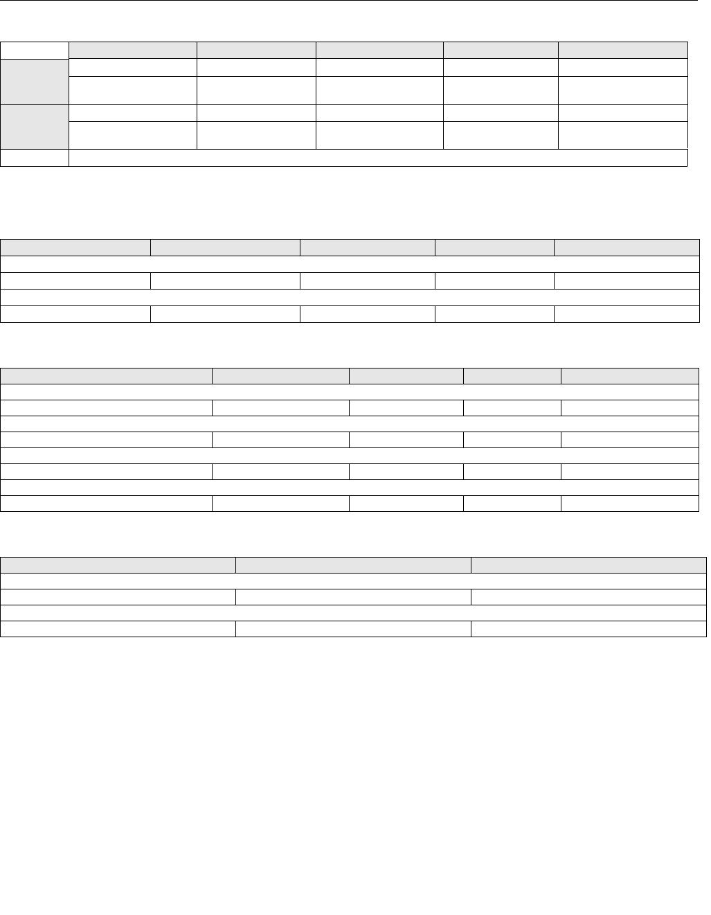
Reference Manual
00809-XXXX-4811, Rev AA
February 2012
A-7
Rosemount 3308
PRELIMINARY
Table A-3. Transition Zones
Table A-4. Measuring Range and Minimum Dielectric Constant
Table A-5. Measuring Range When Using Remote Housing
Table A-6. Maximum recommended Viscosity and Coating / Build-up
Dielectric Constant Rigid Single Lead Flexible Single Lead Coaxial Flexible Twin Lead
Upper(1)
Transition
Zone
(1) The distance from the upper reference point where measurements have reduced accuracy.
TO BE ADDED
Lower(2)
Transition
Zone
(2) The distance from the lower reference point where measurements have reduced accuracy.
Note: The 4–20 mA set points are recommended to be configured between the transition zones, within the measuring range.
Rigid Single Lead Flexible Single Lead Coaxial Rigid Twin Lead Flexible Twin Lead
Maximum Measuring Range
TO BE ADDED
Minimum Dielectric Constant
Rigid Single Lead Flexible Single Lead Coaxial Rigid Twin Lead Flexible Twin Lead
Maximum Measuring Range
TO BE ADDED
Minimum Dielectric Constant with 1 m Remote Housing
Maximum Measuring Range with 2 m Remote Housing
Maximum Measuring Range with 3 m Remote Housing
Coaxial Twin Lead Single Lead
Maximum Viscosity
500 cP 1500 cP 8000 cP (1)
(1) Consult your local Emerson Process Management representative in the case of agitation/turbulence and high viscous products.
Coating / Build-up
Coating not recommended Thin coating allowed, but no bridging Coating allowed

Reference Manual
00809-XXXX-4811, Rev AA
February 2012
Rosemount 3308
A-8
PRELIMINARY
PHYSICAL SPECIFICATION
Housing and Enclosure
Type Dual compartment (removable without opening the tank). Electronics and cabling are separated.
Two entries for conduit or cable connections. The transmitter housing can be rotated in any direction.
Electrical Connection Wireless Black Power Module
Replaceable, Intrinsically Safe Lithium-Thionyl Chloride power module with PBT polymer enclosure. XX year
life at one minute update rate. Reference conditions are 70° F (21° C), and routing data for three additional
network devices.
Note: Continuous exposure to ambient temperature limits (-40 °F or 185 °F) (-40 °C or 85 °C) may reduce
specified power module life by less than 20 %
Field Communicator
Connections Communication Terminal clips permanently fixed to terminal block
Materials of Construction Enclosure
Housing - Low-copper aluminum or stainless steel
Paint - Polyurethane
Cover O-ring - Nitrile butadiene
Terminal Block and Power Module Pack
PBT
Antenna
PBT/PC integrated omnidirectional antenna
Ingress Protection NEMA 4X, IP 66, IP 67
Factory Sealed Yes
Weight Transmitter Head Low-copper Aluminum
3308 without LCD - XX lbs (XX kg)
3308 with M5 LCD - XX lbs (XX kg)
Stainless Steel
3308 without LCD - XX lbs (XX kg)
3308 with M5 LCD - XX lbs (XX kg)
Remote Housing Mounting Kit that includes a flexible armored extension cable and a bracket for wall or pipe mounting.
Tank Connection and Probe
Tank Connection The tank connection consists of a tank seal, a flange,
Tri-Clamp, or NPT or BSP/G threads.
Certain models of flanged Alloy and PTFE covered
probes have a tank connection design with a
protective flange plate of the same material as the
probe and with a backing flange in 316L / EN 1.4404.
The protective flange plate prevents the backing
flange from being exposed to the tank atmosphere.
See “Dimensional Drawings” on page 13.
Flange Dimensions Follows ASME B 16.5, JIS B2220, and EN 1092-1 standards for blind flanges.
For Proprietary Fisher® and Masoneilan® flanges, see “Proprietary Flanges” on page A-13
Vented Flanges Available with Masoneilan and Fisher vented flanges. Vented flanges must be ordered as accessories with a
1½-in. NPT threaded process connection (code RA); see Table on page A-20. As an alternative to a vented
flange, it is possible to use a flushing connection ring on top of the standard nozzle.
Probe Versions Coaxial, Rigid Twin and Rigid Single Lead, Flexible Twin and Flexible Single Lead.
For guidelines on which probe to select depending on application, see the Technical Note Guided Wave
Radar Application Guidelines (Document No. 00840-2600-4811)
For interface measurements Rigid Single probe is the best choice for chamber mounting. The Twin or Coaxial
probe is the preferred choice for clean, low dielectric constant liquids
Material Exposed To
Tank Atmosphere
• Material model code 1: 316L SST (EN 1.4404), PTFE, PFA, and O-ring materials
• Material model code 2: Alloy C-276 (UNS N10276), PTFE, PFA, and O-ring materials
• Material model code 3: Alloy 400 (UNS N04400), PTFE, PFA, and O-ring materials
• Material model code 7: PTFE
• Material model code 8: PTFE, 316L SST (EN 1.4404), and O-ring materials
Pressure Equipment
Directive (PED) Complies with 97/23/EC article 3.3
Tank Seal with Plate Design
Protective Plate
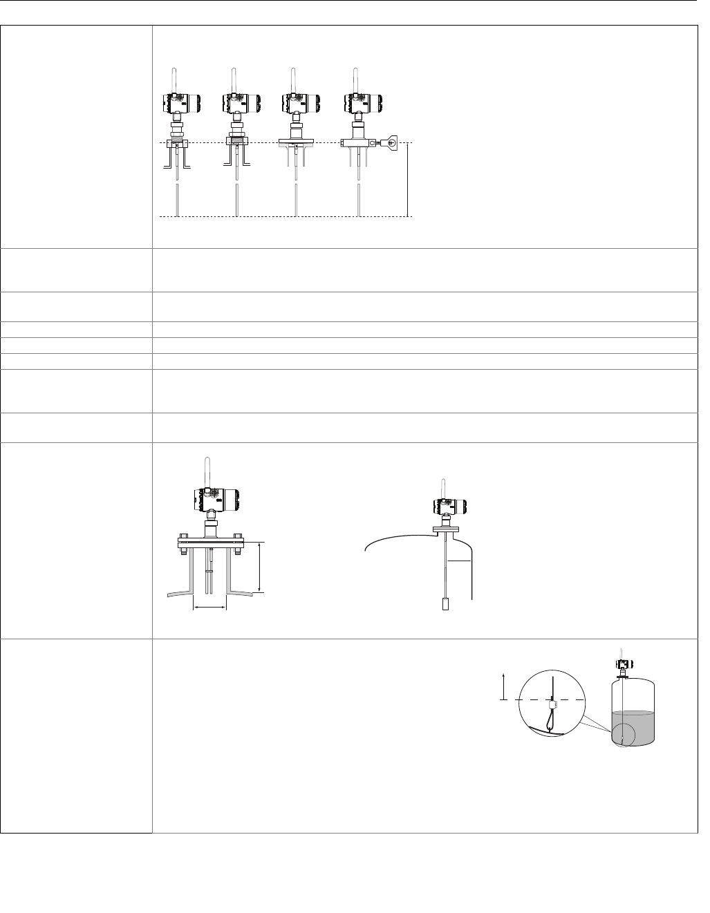
Reference Manual
00809-XXXX-4811, Rev AA
February 2012
A-9
Rosemount 3308
PRELIMINARY
Total Probe Length This is defined from the upper reference point to the end of the probe (weight included, if applicable).
Select the probe length according to the required measuring range (the probe must be hung and fully
extended through the entire distance where level readings are desired).
Cut-to-fit probes Most of the probes can be cut in field. However, there are some restrictions for the standard coaxial probes:
these can be cut up to 2 ft. (0.6 m). Probes shorter than 4.1 ft. (1.25 m) can be cut to the minimum length of
1.3 ft. (0.4 m). The PTFE covered probes cannot be cut in the field.
Minimum and Maximum
Probe Length TO BE ADDED
Probe Angle 0 to 90 degrees from vertical axis
Tensile Strength Flexible Single Lead probe: 2698 lb (12 kN). Flexible Twin Lead probe: 2023 lb (9 kN)
Collapse Load Flexible Single Lead probe: 3597 lb (16 kN)
Sideway Capacity Coaxial probe: 73.7 ft. lbf, 3.7 lb at 19.7 ft. (100 Nm, 1.67 kg at 6 m)
Rigid Twin Lead: 2.2 ft. lbf, 0.22 lb at 9.8 ft. (3 Nm, 0.1 kg at 3 m)
Rigid Single Lead: 4.4 ft. lbf, 0.44 lb at 9.8 ft. (6 Nm, 0.2 kg at 3 m)
Maximum Recommended
Nozzle Height 4 in. (10 cm) + nozzle diameter
For coaxial probes, there are no restrictions
Minimum Clearance
(See Table A-7 on
page A-11)
Other Mechanical
Considerations To get best possible performance, the following must be
considered before installing the transmitter:
• Inlets should be kept at a distance in order to avoid product
filling on the probe
• Avoid physical contact between probes and agitators, as well
as applications with strong fluid movement unless the probe is
anchored
• Probe tie-down is recommended if the probe can move to
within 1 ft. (30 cm) of any object during operations
• In order to stabilize the probe for side forces, it is possible to
fix or guide the probe to the tank bottom
• For optimal single lead probe performance in non-metallic
vessels, the probe must either be mounted with a 2-in. / DN 50 or larger metallic flange, or a metal sheet
with an 8-in. diameter (200 mm) or larger must be used (see the Reference Manual for placement)
Total
Probe
Length
NPT BSP/G Flange Tri-Clamp
Upper
Reference
Point
Nozzle Diameter
Nozzle
Height
Clearance to tank wall
Flexible single lead probe with chuck.
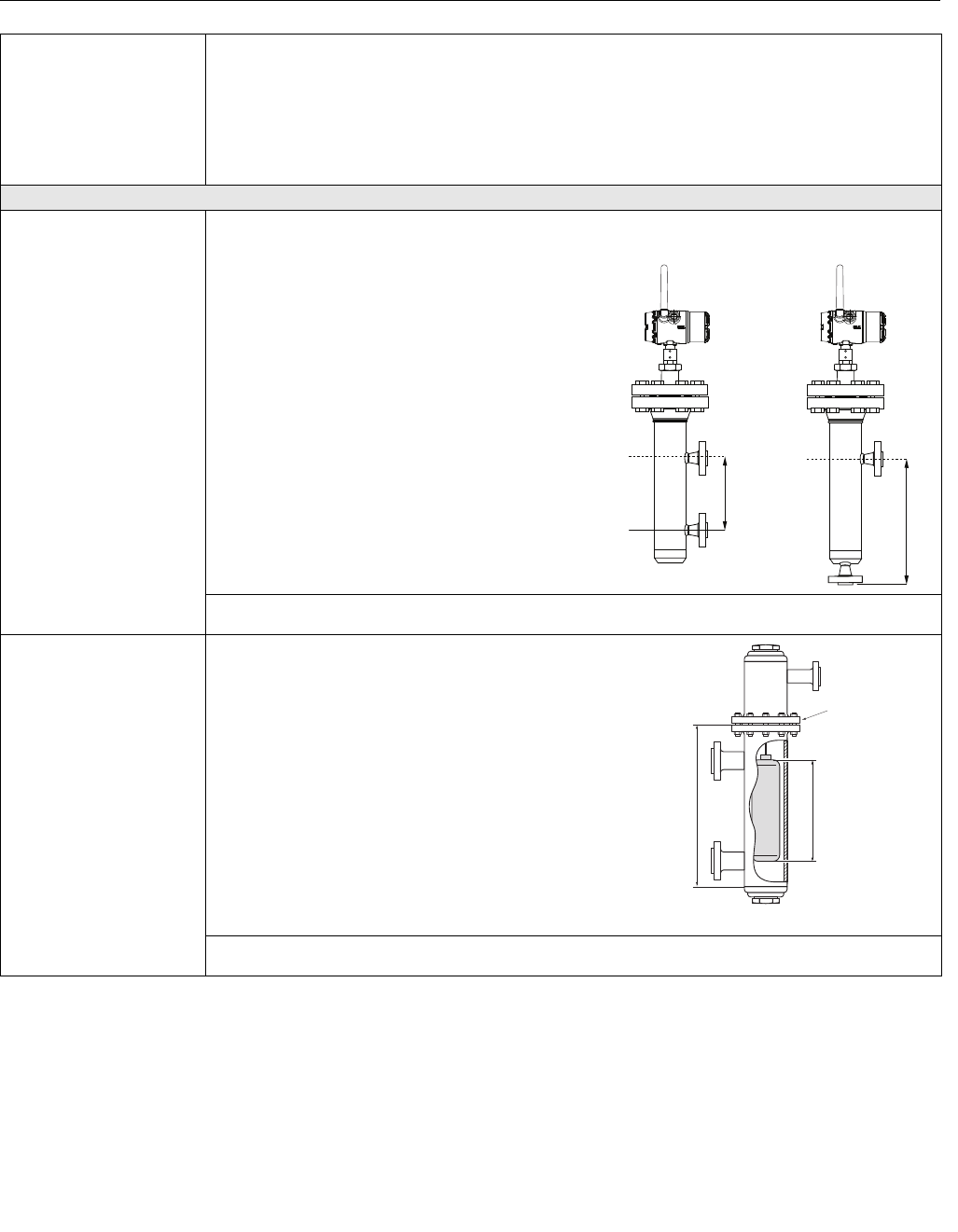
Reference Manual
00809-XXXX-4811, Rev AA
February 2012
Rosemount 3308
A-10
PRELIMINARY
Weight Flange: depends on flange size
Coaxial probe: 0.67 lb/ft. (1 kg/m)
Rigid Single Lead probe (0.3 in./8 mm): 0.27 lb/ft. (0.4 kg/m)
Rigid Single Lead probe (0.5 in./13 mm): 0.71 lb/ft. (1.06 kg/m)
Rigid Twin Lead probe: 0.40 lb/ft. (0.6 kg/m)
Flexible Single Lead probe: 0.05 lb/ft. (0.07 kg/m)
Flexible Twin Lead probe: 0.09 lb/ft. (0.14 kg/m)
End weight: 0.88 lb (0.40 kg) for single probes, 1.3 lb (0.60 kg) for twin probes
Chamber / Pipe Installations
Rosemount 9901 Chamber Rosemount 9901 allows external mounting of process level
instrumentation. It supports a variety of process
connections, and optional drain and vent connections. The
Rosemount 9901 chamber is designed to the ASME B31.3
standard, and is Pressure Equipment Directive (PED)
compliant. Use option code XC to order together with the
3308 transmitter.
The probe length to use for a Rosemount 9901 chamber
can be calculated with this formula:
Side-and-Side dimension:
Probe length=Centre-to-Centre dimension+19 in. (48 cm)
Side-and-Bottom dimension:
Probe length=Centre-to-Centre dimension+4 in. (10 cm)
Use a centering disc the same diameter as the
chamber if the probe length >3.3 ft. (1 m). See “Probe Type
in Chamber Considerations” on page A-11 and “Centering
Discs” on page A-11 for which probe and disc to use.
For additional information, see the Rosemount 9901 Chamber for Process Level Instrumentation
Product Data Sheet (Document Number 00813-0100-4601)
Existing Chamber A Rosemount 3308 transmitter is the perfect replacement
in an existing displacer chamber.
Proprietary flanges are offered, enabling use of existing
chambers to make installation easy.
Considerations when changing to the
Rosemount 3308 transmitter:
The Rosemount 3308 transmitter flange choice and probe
length must be correctly matched to the chamber. Both
standard ANSI and EN (DIN), as well as proprietary
chamber flanges, are available. See “Proprietary Flanges”
on page A-13 to identify the proprietary flanges.
See “Probe Type in Chamber Considerations” on
page A-11 and “Centering Discs” on page A-11 for which
probe and disc to use. See Table A-8 on page A-12 for
guidelines on the required probe length.
For additional information, see the Replacing Displacers with Guided Wave Radar Technical Note
(Document Number 00840-2200-4811)
Side-and-Side
dimension
Side-and-Bottom
dimension
Center to Center
Center to Center
Replace
chamber
flange
Displacer
Length
Probe
Length

Reference Manual
00809-XXXX-4811, Rev AA
February 2012
A-11
Rosemount 3308
PRELIMINARY
Table A-7. Minimum Clearance
Probe Type in Chamber
Considerations When installing a Rosemount 3308 transmitter in a chamber, the single lead probe is recommended.
The recommended minimum chamber diameter is 4 in. (100 mm) for Single Flexible probe and 3 in. (75 mm)
for the Single Rigid probe. The probe should be centered to prevent it touching the sides of the well.
The probe length determines if a Single Rigid or Single Flexible probe should be used:
• Less than 19.7 ft. (6.0 m):
Rigid Single Probe is recommended. Use a centering disc for probe > 3.3 ft. (1 m). If installation requires
less head-space, use a Flexible Single Probe with a weight and centering disc.
• More than 19.7 ft. (6.0 m):
Use Flexible Single Probe with a weight and centering disc.
A short weight is available for the single flexible SST probe. It is used for measuring close to the probe end
and shall be used where the measuring range must be maximized. The height is 2 in. (50 mm) and the
diameter is 1.5 in. (37.5 mm). The option code is W2.
If a heavier weight is needed, option code W3 can be used (height is 5.5 in. (140 mm) and the diameter is 1.5
in. (37.5 mm).
Centering Discs To prevent the probe from contacting the chamber or pipe wall, centering discs are available for
rigid single, flexible single, and flexible twin lead probes. The disc is attached to the end of the
probe. Discs are made of stainless steel, Alloy C-276, Alloy 400, or PTFE. See Table A-9 for
Dimension D. Table A-10 shows which centering disc diameter to choose for a particular pipe.
D
Coaxial Rigid Twin Lead Flexible Twin Lead Rigid Single Lead Flexible Single Lead
Recommended
nozzle diameter Enough space to fit
the probe(1) 4 in. (10 cm) or more 4 in. (10 cm) or more 6 in. (15 cm) or more 6 in. (15 cm) or more
Min. nozzle
diameter(2) Enough space to fit
the probe(1) 2 in. (5 cm) 2 in. (5 cm) 2 in. (5 cm) 2 in. (5 cm)
Min. clearance to
tank wall or
obstruction(3)
0 in. (0 cm) 4 in. (10 cm) 4 in. (10 cm) 4 in. (10 cm) if
smooth metallic wall.
12 in. (30 cm) if
disturbing objects,
rugged metallic or
concrete/plastic wall.
4 in. (10 cm) if
smooth metallic wall.
12 in. (30 cm) if
disturbing objects,
rugged metallic or
concrete/plastic wall.
Min. pipe / bypass
diameter 1.5 in. (3.8 cm) 2 in. (5 cm) (4) Consult your local
Emerson Process
Management
representative.
2 in. (5 cm) (5) Consult your local
Emerson Process
Management
representative.
(1) Probe diameter is 1.1 in. (28 mm) for standard probe.
(2) Requires special configuration and setting of Upper Null Zone.
(3) Minimum clearance from tank bottom for the coaxial and rigid single probes is 0.2 in. (5 mm).
(4) The center-most lead must be at least 0.6 in. (15 mm) away from the pipe/bypass wall.
(5) The probe must be centered in the pipe/bypass.
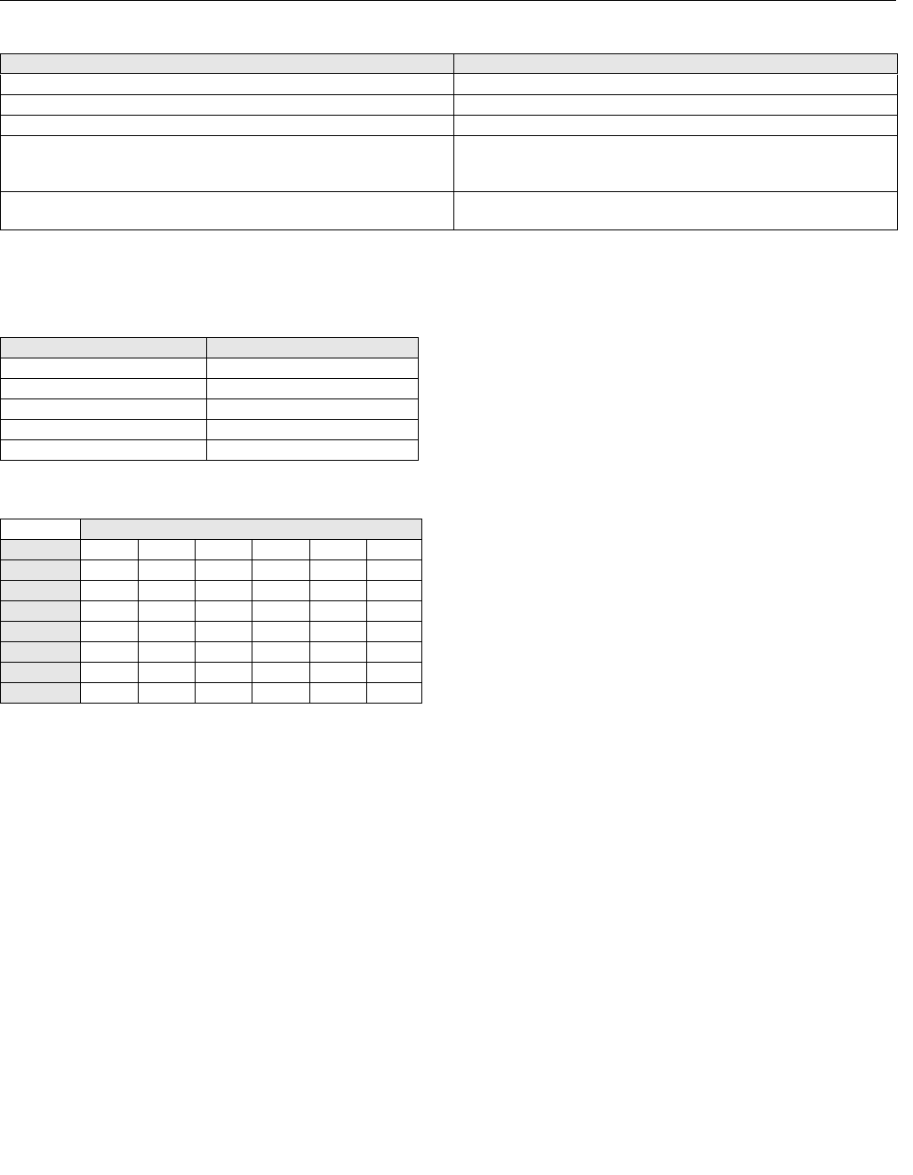
Reference Manual
00809-XXXX-4811, Rev AA
February 2012
Rosemount 3308
A-12
PRELIMINARY
Table A-8. Required probe length in chambers
Table A-9. Centering Discs Dimensions
Table A-10. Centering disc size recommendation for different pipe schedules
Chamber Manufacturer Probe Length(1)
(1) If flushing ring is used, add the ring height to the probe length.
Major torque-tube manufacture (249B, 249C, 2449K, 249N, 259B) Displacer+9 in. (229 mm)
Masoneilan (Torque tube operated), proprietary flange Displacer+8 in. (203 mm)
Other - torque tube(2)
(2) For other manufacturers, there are small variations. This is an approximate value, actual length should be verified.
Displacer+8 in. (203 mm)
Magnetrol (spring operated)(3)
(3) Lengths vary depending on model, SG and rating, and should be verified.
Displacer+between
7.8 in. (195 mm) to
15 in. (383 mm)
Others - spring operated(2) Displacer+19.7 in.
(500 mm)
Disc Size Actual Disc Diameter
2 in. 1.8 in. (45 mm)
3 in. 2.7 in. (68 mm)
4 in. 3.6 in. (92 mm)
6 in. 5.55 in. (141 mm)
8 in. 7.40 in. (188 mm)
Pipe Schedule
Pipe Size 5s, 5 10s,10 40s, 40 80s, 80 120 160
2 in. 2 in. 2 in. 2 in. 2 in. NA(1)
(1) Schedule is not available for pipe size.
NA(2)
(2) No centering disc is available.
3 in. 3 in. 3 in. 3 in. 3 in. NA(1) 2 in.
4 in. 4 in. 4 in. 4 in. 4 in. 4 in. 3 in.
5 in. 4 in. 4 in. 4 in. 4 in. 4 in. 4 in.
6 in. 6 in. 6 in. 6 in. 6 in. 4 in. 4 in.
7 in. NA(1) NA(1) 6 in. 6 in. NA(1) NA(1)
8 in. 8 in. 8 in. 8 in. 8 in. 6 in. 6 in.
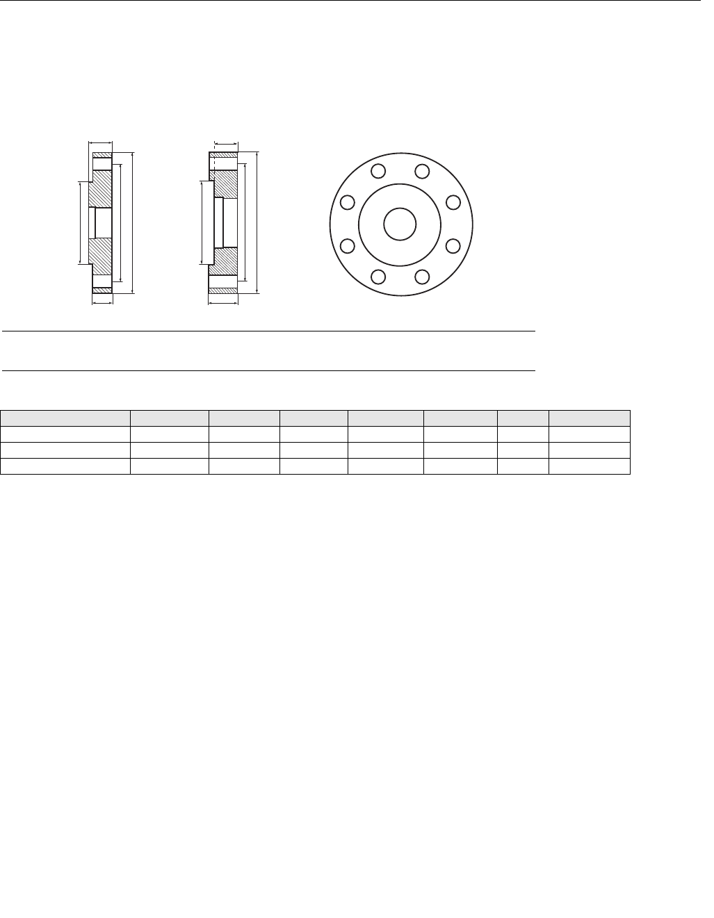
Reference Manual
00809-XXXX-4811, Rev AA
February 2012
A-13
Rosemount 3308
PRELIMINARY
DIMENSIONAL DRAWINGS
TO BE ADDED
Proprietary Flanges
Table A-11. Dimensions of proprietary flanges
Special Flanges(1)
(1) These flanges are also available in a vented version.
D B1B2F G # Bolts K
Fisher 249B/259B(2)
(2) Flange with raised face.
9.00 (228.6) 1.50 (38.2) 1.25 (31.8) 0.25 (6.4) 5.23 (132.8) 8 7.25 (184.2)
Fisher 249C(3)
(3) Flange with recessed face.
5.69 (144.5) 0.94 (23.8) 1.13 (28.6) -0.19 (-4.8) 3.37 (85.7) 8 4.75 (120.65)
Masoneilan(2) 7.51 (191.0) 1.54 (39.0) 1.30 (33.0) 0.24 (6.0) 4.02 (102.0) 8 5.87 (149.0)
D
B1
G
Raised Face Recessed Face
K
D: Outside diameter
B1: Flange thickness with
gasket surface
B2: Flange thickness without
gasket surface
F=B1-B2: Gasket surface
thickness
G: Gasket surface diameter
# Bolts: Number of Bolts
K: Bolt hole circle diameter
NOTE
Dimensions may be used to aid in the identification of installed flanges. It is not intended for manufacturing use.
G
B1
DK
B2B2
Dimensions are in inches (millimeter).

Reference Manual
00809-XXXX-4811, Rev AA
February 2012
Rosemount 3308
A-14
PRELIMINARY
ORDERING INFORMATION
3308 Wireless Guided Wave Radar Level Transmitter Ordering Information
★The Standard offering represents the most common options. The starred options (★) should be selected for best delivery.
The Expanded offering is subject to additional delivery lead time.
Model Product Description
3308A Guided Wave Radar Level Transmitter
Code Profile
Standard Standard
S Standard ★
O Upstream Oil & Gas, Transmitter optimized for upstream oil and gas ★
RRefining ★
C Chemical ★
T Tank Gauging ★
MMarine ★
Signal Output
Standard Standard
XWirelessHART ★
Special
NNone(1)
Measurement Type
Standard Standard
2Level and Interface Transmitter ★
Expanded
1Level or Interface Transmitter (interface available for fully submerged probe)
Special
9Spare Process Seal & Probe
Housing Material
Standard Standard
DWireless PlantWeb housing, Aluminum ★
Expanded
EWireless PlantWeb housing, Stainless Steel
Special
N E(1)
Conduit Threads
Standard Standard
1½–14 NPT ★
Special
0None(1)
Operating Temperature and Pressure Probe Type
Standard Standard
S- 15 psi (-1bar) to 580 psi (40 bar) @ 302 °F (150 °C) ★
Expanded
PHigh Pressure
MMedium Temperature and Pressure
HHigh Temperature and Pressure
Special
XSpecial Temperature and Pressure Rating
NNone(2)

Reference Manual
00809-XXXX-4811, Rev AA
February 2012
A-15
Rosemount 3308
PRELIMINARY
Material of Construction: Process Connection / Probe Probe Type
Standard Standard
1316L SST (EN 1.4404) ★
Expanded
2Alloy C-276 (UNS N10276). With plate design if flanged version.
Up to class 600, PN 63.
3Alloy 400 (UNS N04400). With plate design if flanged version.
Up to class 600, PN 63.
7PTFE covered probe and flange. With plate design.
8PTFE covered probe
LAlloy 625 (UNS N06625) process connection, flange, and probe.
H
Alloy C-276 (UNS N10276) process connection, flange, and probe.
MAlloy 400 (UNS N04400) process connection, flange, and probe.
DAlloy 2205 (UNS S32205/S38103) process connection, flange,
and probe.
Special
XSpecial material of construction
0None(2)
Sealing, O-ring Material
Standard Standard
VFluoroelastomer (FKM) ★
EEthylene Propylene ★
KPerfluoroelastomer (FFKM) ★
BNitrile butadiene ★
Expanded
FFVMQ (Fluorosilicon)
Special
XSpecial O-ring
NNone(3)
Probe Type Process Connection Probe Lengths
Standard Standard
1A Rigid Twin Lead Min.: 1 ft. 4 in. (0.4 m)
Max: 9 ft. 10 in. (3 m)
2A Flexible Twin Lead with weight Min.: 1 ft. 4 in. (0.4 m)
Max: 32 ft. 10 in. (10 m)
★
5A Flexible Single Lead (Ø 0.16 in./4 mm) Min.: 1 ft. 4 in. (0.4 m)
Max: 32 ft. 10 in. (10 m)
★
Expanded
3A Coaxial Min.: 1 ft. 4 in. (0.4 m)
Max: 19 ft. 8 in. (6 m)
3B Perforated Coaxial Probe Min.: 1 ft. 4 in. (0.4 m)
Max: 19 ft. 8 in. (6 m)
4A Rigid Single Lead 0.3 in. (8 mm) Min.: 1 ft. 4 in. (0.4 m)
Max: 9 ft. 10 in. (3 m)
4B Rigid Single Lead 0.5 in. (13 mm) Min.: 1 ft. 4 in. (0.4 m)
Max: 19 ft. 8 in. (6 m)
4E Rigid Single Lead with Integrated Pipe Min.: 1 ft. 4 in. (0.4 m)
Max: 19 ft. 8 in. (6 m)
6A Flexible Single Lead, standard weight
(Ø 0.24 in./6 mm)
Min.: 1 ft. 4 in. (0.4 m)
Max: 32 ft. 10 in. (10 m)
6B Flexible Single Lead with chuck
(Ø 0.24 in./6 mm)
Min.: 1 ft. 4 in. (0.4 m)
Max: 32 ft. 10 in. (10 m)

Reference Manual
00809-XXXX-4811, Rev AA
February 2012
Rosemount 3308
A-16
PRELIMINARY
Special
XX Special Probe
0N Use when ordering a Spare
Transmitter Head
Probe Length Units
Standard Standard
EEnglish (feet, inch) ★
MMetric (meters, centimeters) ★
Special
NNot applicable(2)
Probe Length (feet / meters)
Standard Standard
XXX 0-30 feet or 0-10 meters ★
Special
000 Not applicable(2)
Probe Length (inches / centimeters)
Standard Standard
XX 0-11 inches or 0-99 centimeters ★
Special
00 Not applicable(2)
Process Connection Size (ANSI / EN / JIS)
Standard Standard
51 ½ in., Threaded connections and Tri-Clamp only ★
22 in. / DN50 / 50A ★
33 in. / DN80 / 80A ★
44 in. / DN100 / 100A ★
Expanded
11 in., Threaded connections only
66 in. / DN150 / 150A
88 in. / DN200 / 200A
PProprietary flanges
Special
XSpecial
NNone(2)
Process Connection Rating
Standard Standard
NN For use with non-flange process connection type(2) ★
ANSI Ratings
AA ASME B16.5 Class 150 Flange ★
AB ASME B16.5 Class 300 Flange ★
AC ASME B16.5 Class 600 Flange ★
AD ASME B16.5 Class 900 Flange ★
AE ASME B16.5 Class 1500 Flange ★
EN Ratings
DA EN1092-1 PN16 Flange ★
DB EN1092-1 PN40 Flange ★
DC EN1092-1 PN63 Flange ★
DD EN1092-1 PN100 Flange ★
DE EN1092-1 PN160 Flange ★
JIS Ratings
JA JIS 10K Flange ★

Reference Manual
00809-XXXX-4811, Rev AA
February 2012
A-17
Rosemount 3308
PRELIMINARY
JB JIS 20K Flange ★
PF Proprietary Flange, for use with proprietary flange process connection type ★
Expanded
ANSI Ratings
AF ASME B16.5 Class 2500 Flange
EN Ratings
DF EN1092-1 PN250 Flange
DG EN1092-1 PN320 Flange
JIS Ratings
JC JIS 30K Flange
JD JIS 40K Flange
Special
XX Special
Process Connection Type
Standard Standard
Threads
NNPT Thread ★
GBSPP (G) Thread ★
Flange Faces
FFlat Face (FF) Flange, standard face for EN flanges ★
RRaised Face (RF) Flange, standard face for ANSI / JIS flanges ★
Proprietary Flanges
MMasoneilan-Proprietary, 316 SST Torque Tube Flange ★
PFisher-Proprietary, 316 SST, (for 249B cages) Torque Tube Flange ★
QFisher-Proprietary, 316 SST, (for 249C cages) Torque Tube Flange ★
CTri-Clamp
XSpecial ★
0None(2) ★
Expanded (Flange Faces)
TRing Type Joint (RTJ) Flange
VDIN 2513 Form V13 Flange
IDIN 2513 Form R13 Flange
DDIN 2512 Form F Flange
Product Certifications
Standard Standard
I1 ATEX Intrinsic Safety ★
I2 INMETRO Intrinsic Safety ★
I3 NEPSI Intrinsic Safety ★
I4 TIIS Intrinsic Safety ★
I5 FM Intrinsic Safety and Non-Incendive ★
I6 CSA Intrinsic Safety and Non-Incendive ★
I7 IECEx Intrinsic Safety ★
Expanded
KD ATEX and CSA Intrinsic Safety
KE FM and CSA Intrinsic Safety
KF ATEX and FM Intrinsic Safety
NA No Hazardous Locations Certifications

Reference Manual
00809-XXXX-4811, Rev AA
February 2012
Rosemount 3308
A-18
PRELIMINARY
Wireless Options
Update Rate, Operating Frequency and Protocol
Standard Standard
WA3 User Configurable Update Rate, 2.4 GHz DSSS, IEC 62591 (WirelessHART) ★
Omnidirectional Wireless Antenna and SmartPower Solutions
Standard Standard
WK1 External Antenna, Adapter for Black Power Module (I.S. Power Module Sold Separately) ★
WM1 Extended Range, External Antenna, Adapter for Black Power Module ★
Expanded
WN1 High Gain, Remote Antenna, Adapter for Black Power Module (I.S. Power Module Sold Separately)
Options
Display Type
Standard Standard
M5 PlantWeb LCD Display ★
Hydrostatic Testing
Standard Standard
P1 Hydrostatic Testing, including certificate ★
Factory Configuration
Standard Standard
C1 Factory Configuration per CDS ★
Special Quality Assurance
Standard Standard
Q4 Calibration Data Certificate ★
Quality Traceability Certification
Standard Standard
Q8 Material Traceability Certification per EN 10204 3.1 ★
Welding Procedure Qualification
Expanded
Q66 Welding Procedure Qualification Record Documentation
Special Certifications
Expanded
QG GOST Certification
Materials Certification MR0175
Standard Standard
Q15 NACE Material Recommendation per MR0175 ★
Materials Certification MR0103
Standard Standard
Q25 NACE Material Recommendation per MR0103 ★
Installation Options
Standard Standard
LS Long Stud for Flexible Single Lead Probes, 10 in. (25 cm) ★
Expanded
BR Mounting Bracket for 1.5 in. NPT Process Connection (RA)
Weight and Anchoring Options for Flexible Single Probes
Standard Standard
W1 Small weight, Length: 5.5 in. (140 mm), Diameter: 0.86 in. (22 mm). For narrow process connections. ★
W3 Heavy weight, Length: 5.5 in. (140 mm), Diameter: 1.5 in. (37.5 mm). Use for liquid applications. ★
W4 Chuck, for anchoring of probe in tank bottom ★

Reference Manual
00809-XXXX-4811, Rev AA
February 2012
A-19
Rosemount 3308
PRELIMINARY
Expanded
W2 Short weight, Length: 2 in. (50 mm), Diameter: 1.5 in. (37.5 mm). For limited space below measuring range.
Weight Assembly Options for Flexible Single Probes
Standard Standard
WU Weight not mounted on probe. Recommended for cutting probe in field. ★
Guaranteed Startup
Expanded
GS Guaranteed Startup at -50 °C (Unpublished)
Conduit Plug
Expanded
DO 316 SST Conduit Plug
PlantWeb Diagnostic Functionality
Standard Standard
DA1 HART Diagnostics Suite ★
Centering Disc
Standard Standard
S2 2 in. Centering Disc ★
S3 3 in. Centering Disc ★
S4 4 in. Centering Disc ★
P2 2 in. Centering Disc PTFE ★
P3 3 in. Centering Disc PTFE ★
P4 4 in. Centering Disc PTFE ★
Expanded
S6 6 in. Centering Disc
S8 8 in. Centering Disc
P6 6 in. Centering Disc PTFE
P8 8 in. Centering Disc PTFE
Remote Housing Mounting
Expanded
B1 3.2 ft. (1 m) Remote Housing Mounting Cable and Bracket
B2 6.5 ft. (2 m) Remote Housing Mounting Cable and Bracket
B3 9.8 ft. (3 m) Remote Housing Mounting Cable and Bracket
Assemble / Consolidate to Chamber
Standard Standard
XC Consolidate to Chamber ★
Expanded
XA Assemble to Chamber
Specials
RXXXX Special TBD (Unpublished)
(1) Use when ordering a Spare Probe.
(2) Use when ordering a Spare Transmitter Head.
(3) Use when ordering a Spare Transmitter Head.

Reference Manual
00809-XXXX-4811, Rev AA
February 2012
Rosemount 3308
A-20
PRELIMINARY
Accessories Rosemount 3308
Code Process Connection - Size/Type (consult factory for other process connections)
Centering discs(1) (2) Outer Diameter
Standard Standard
03300-1655-0001 Kit, 2-in. Centering Disc, SST, Rigid Single 1.8 in. (45 mm) ★
03300-1655-0002 Kit, 3-in. Centering Disc, SST, Rigid Single 2.7 in. (68 mm) ★
03300-1655-0003 Kit, 4-in. Centering Disc, SST, Rigid Single 3.6 in. (92 mm) ★
03300-1655-0006 Kit, 2-in. Centering Disc, PTFE, Rigid Single 1.8 in. (45 mm) ★
03300-1655-0007 Kit, 3-in. Centering Disc, PTFE, Rigid Single 2.7 in. (68 mm) ★
03300-1655-0008 Kit, 4-in. Centering Disc, PTFE, Rigid Single 3.6 in. (92 mm) ★
03300-1655-1001 Kit, 2-in. Centering Disc, SST, Single / Twin Flex Lead 1.8 in. (45 mm) ★
03300-1655-1002 Kit, 3-in. Centering Disc, SST, Single / Twin Flex Lead 2.7 in. (68 mm) ★
03300-1655-1003 Kit, 4-in. Centering Disc, SST, Single / Twin Flex Lead 3.6 in. (92 mm) ★
03300-1655-1006 Kit, 2-in. Centering Disc, PTFE, Single / Twin Flex Lead 1.8 in. (45 mm) ★
03300-1655-1007 Kit, 3-in. Centering Disc, PTFE, Single / Twin Flex Lead 2.7 in. (68 mm) ★
03300-1655-1008 Kit, 4-in. Centering Disc, PTFE, Single / Twin Flex Lead 3.6 in. (92 mm) ★
Expanded
03300-1655-0004 Kit, 6-in. Centering Disc, SST, Rigid Single 5.55 in. (141 mm)
03300-1655-0005 Kit, 8-in. Centering Disc, SST, Rigid Single 7.40 in. (188 mm)
03300-1655-0009 Kit, 6-in. Centering Disc, PTFE, Rigid Single 5.55 in. (141 mm)
03300-1655-0010 Kit, 8-in. Centering Disc, PTFE, Rigid Single 7.40 in. (188 mm)
03300-1655-1004 Kit, 6-in. Centering Disc, SST, Single / Twin Flex Lead 5.55 in. (141 mm)
03300-1655-1005 Kit, 8-in. Centering Disc, SST, Single / Twin Flex Lead 7.40 in. (188 mm)
03300-1655-1009 Kit, 6-in. Centering Disc, PTFE, Single / Twin Flex Lead 5.55 in. (141 mm)
03300-1655-1010 Kit, 8-in. Centering Disc, PTFE, Single / Twin Flex Lead 7.40 in. (188 mm)
Vented Flanges(3)
Expanded
03300-1812-0092 Fisher 249B/259B(4)
03300-1812-9002 Fisher 249C(4)
03300-1812-9003 Masoneilan(4)
Other
Standard Standard
03300-7004-0001 Viator HART Modem and cables (RS232 connection) ★
03300-7004-0002 Viator HART Modem and cables (USB connection) ★
(1) If a centering disc is required for a flanged probe, the centering disc can be ordered with options Sx or Px on page A-19 in the model code. If a centering
disc is required for a threaded connection or as a spare part, it should be ordered using the item numbers listed below.
(2) To order a centering disc in a different material, consult the factory.
(3) 1½ in. NPT threaded connection (RA) is required.
(4) For pressure and temperature rating, see “Fisher & Masoneilan Flange Rating” on page A-3.
Reference Manual
00809-XXXX-4811, Rev AA
February 2012 Rosemount 3308
www.rosemount.com
PRELIMINARY
Appendix B Product Certifications
Safety Messages . . . . . . . . . . . . . . . . . . . . . . . . . . . . . . . . . page B-1
SAFETY MESSAGES Procedures and instructions in this section may require special precautions to
ensure the safety of the personnel performing the operations. Information that
raises potential safety issues is indicated by a warning symbol ( ). Please
refer to the following safety messages before performing an operation
preceded by this symbol.
Explosions could result in death or serious injury:
Verify that the operating environment of the gauge is consistent with the appropriate
hazardous locations certifications.
Before connecting a HART-based communicator in an explosive atmosphere, make
sure the instruments in the loop are installed in accordance with intrinsically safe or
non-incendive field wiring practices.
In an Explosion-proof/Flameproof installation, do not remove the transmitter cover when
power is applied to the unit.
Failure to follow safe installation and servicing guidelines could result in death or
serious injury:
Make sure the transmitter is installed by qualified personnel and in accordance with
applicable code of practice.
Use the equipment only as specified in this manual. Failure to do so may impair the
protection provided by the equipment.
Do not perform any service other than those contained in this manual unless you are
qualified.
A safety isolator such as a zener barrier is always needed for intrinsic safety.

Reference Manual
00809-XXXX-4811, Rev AA
February 2012
Rosemount 3308
B-2
PRELIMINARY
PLACEHOLDER FOR APPROVALS INFORMATION
High voltage that may be present on leads could cause electrical shock:
Avoid contact with leads and terminals.
Make sure the main power to the Radar Transmitter is off and the lines to any other
external power source are disconnected or not powered while wiring the transmitter.
Probes covered with plastic and/or with plastic discs may generate an ignition-capable
level of electrostatic charge under certain extreme conditions. Therefore, when the
probe is used in a potentially explosive atmosphere, appropriate measures must be
taken to prevent electrostatic discharge.

Reference Manual
00809-XXXX-4811, Rev AA
February 2012 Rosemount 3308
www.rosemount.com
PRELIMINARY
Index
A
Agitators . . . . . . . . . . . 2-9, 4-10
Amplitude Threshold Settings 7-12
Amplitude Thresholds . . . . . . . 7-4
AMS suite . . . . . . . . . . . . . . . 2-6
AMS Wireless Configurator . . . 3-6
Anchoring . . . . . . . . . . . . . . 4-15
Applications . . . . . . . . . . . . . 2-3
B
Bridging . . . . . . . . . . . . . . . . A-6
BSP/G threads . . . . . . . . . . 4-11
C
Calibration . . . . . . . . . . . . . . 7-9
Calibration Offset . . . . . . . . . . 7-2
Canadian Standards Association
system control drawing . . B-2
Centering Disc . . . . . . . . . . . 4-17
Centering disc . . . . . . . . . . . . 4-8
Centering piece . . . . . . . . . . 4-14
Changing the Probe . . . . . . . 7-18
Coating . . . . . . . . . . . . . . . . . A-6
COMM terminals . . . . . . 3-7, 5-2
Configuration . . . . . . . . . . . . . 5-3
basic . . . . . . . . . . . . . . . 5-3
Handheld Communicator . 5-8
volume . . . . . . . . . . . . . . 5-6
D
Damping . . . . . . . . . . . . . . . . 7-7
Dead Zones . . . . . . . . . . . . 2-12
Device Network Configuration . 3-6
Device Revision . . . . . . . . . . . 1-1
Diagnostic messages . 7-20, 7-21
Dielectric Constant
Upper Product . . . . . . . . . 5-4
Vapor . . . . . . . . . . . . . . . 5-4
Dielectric constant . . . . . . . . . 2-7
Dielectric constant calculator . . 2-7
Disk Logging . . . . . . . . . . . . . 7-4
Display Panel . . . . . . . . . . . 5-11
Disturbances
Upper Null Zone . . . . . . 7-10
E
Emulsion layers . . . . . . . . . . . 2-8
Errors . . . . . . . . . . . . . . . . 7-20
F
Factory Mutual
system control drawing . . B-2
fast key sequence . . . . . . . . . 3-7
Field Communicator . . . . . . . 5-8
Field Device Revision . . . . . . 1-1
Flange Connection . . . . . . . . 4-6
Foam . . . . . . . . . . . . . . . . . . A-6
Free Space . . . . . . . . . . . . . . 4-9
H
HART Communicator . . . . . . . 5-8
Heating Coils . . . . . . . . . . . . 2-9
Heating coils . . . . . . . . . . . . 4-10
High Level Rates . . . . . . . . . . 7-7
I
Immersed Probe . . . . . . . . . . 7-8
Installation
flange connection . . . . . . 4-6
Free Space . . . . . . . . . . 4-9
mounting considerations . 4-5
mounting position . . . . . 4-10
procedure . . . . . . . . . . . 4-3
shortening the probe . . . 4-13
Still pipes . . . . . . . . . . . . 4-8
threaded connection . . . . 4-5
Interface . . . . . . . . . . . . . . . . 2-7
fully immersed probes . . . 7-8
low dielectric constants . . 7-5
L
Level and Distance Calibration 7-9
Logging . . . . . . . . . . . . . . . 7-14
Lower Transition Zone . . . . . 2-12
M
Maximum Upper Product Thickness
5-11
Measurement Mode . . . . . . 5-11
Measurement Principle . . . . . 2-3
Measurement Units . . . . . . . . 5-9
Memory Map . . . . . . . . . . . 7-16
Mounting Position . . . . . . . . 4-10
MSDS . . . . . . . . . . . . . . . . .2-13
N
Non-metallic tanks . . . . . . . . .4-7
Nozzle
maximum height . . . . . . .4-6
minimum diameter . . . . . .4-6
NPT threads . . . . . . . . . . . . 4-11
O
OSHA . . . . . . . . . . . . . 1-3, 2-13
P
Pipe Installations
Centering Disc . . . . . . . .4-17
Plate design . . . . . . . . . . . . .4-12
Power Module . . . . . . . . . . . .3-7
power module . . . . . . . . . . . .6-2
Power Module Installation . . . .3-5
Primary Variable . . . . . . . . . . .5-9
Probe
anchoring . . . . . . . . . . .4-15
changing . . . . . . . . . . . .7-18
shortening . . . . . . . . . . .4-13
Probe Angle . . . . . . . . . 5-5, 5-11
Probe Length . . . . . . . . . 5-4, 5-9
Probe Type . . . . . . . . . 5-4, 5-10
Probe types . . . . . . . . . . . . .2-10
Process connection . . . . . . . .4-5
Product Dielectric . . . . . . . . .5-10
R
Radar Configuration Tool . . . .2-6
Range Values . . . . . . . . . . .5-12
RCT
Logging . . . . . . . . . . . . .7-14
Logging the plot . . . . . . . .7-4
Saving the configuration .7-15
Waveform Plot . . . . . . . . .7-3
Recommended mounting position
4-10
Recycling . . . . . . . . . . . . . . .2-13
return process . . . . . . . . . . .2-13
Rosemount 751 . . . . . . . . . . .2-6

Reference Manual
00809-XXXX-4811, Rev AA
February 2012
Rosemount 3308
Index-2
PRELIMINARY
S
Save Setup . . . . . . . . . . . . . 7-15
Setup
Save configuration . . . . . 7-15
Shipping Considerations . . . . 2-13
Software write protect . . . . . . . 4-4
Standard Tank Shapes . . . . . . 5-7
Strapping Table . . . . . . 5-6, 5-13
System Architecture . . . . . . . . 2-6
T
Tank connection . . . . . . . . . 4-12
flange . . . . . . . . . . . . . . 4-12
Tank Dimensions . . . . . . . . . 5-13
Tank Geometry . . . . . . . . . . . 5-3
Tank Height . . . . . 5-4, 5-9, 7-2
Tank shape . . . . . . . . . . . . . . 2-9
Tank Shapes . . . . . . . . . . . . . 5-7
Tank Type . . . . . . . . . . 5-6, 5-13
Temperature Limits . . . . . . . . A-2
Threaded connection . . . . . . . 4-5
Threshold Settings . . . . . . . . 7-12
Time Domain Reflectometry . . 2-3
Transition Zones . . . . . . . . . 2-12
Transmitter Head
removing . . . . . . . . . . . 7-17
Transmitter housing . . . . . . . 2-10
Transmitter Reference Point . . 7-2
Transmitter Variables . . . . . . 5-13
Tri-loop . . . . . . . . . . . . . . . . . 2-6
Trim Near Zone . . . . . . . . . . 7-10
Troubleshooting . . . . . . . . . . 7-19
Turbulent conditions . . . . . . . 4-10
U
UNZ . . . . . . . . . . . . . . 4-6, 7-10
Upper Null Zone . 4-6, 5-5, 7-10
Upper Reference Point . . 5-3, 7-2
Upper Transition Zone . . . . . 2-12
V
Vapor . . . . . . . . . . . . . . . . . . A-6
Vapor Dielectric . . . . . . . . . . 5-10
Vessel characteristics . . . . . . . 2-9
Volume Configuration . . 5-6, 5-13
Volume Units . . . . . . . . . . . . 5-13
W
Warnings . . . . . . . . . . . . . . 7-21
Waveform plot . . . . . . . . . . . . 7-3
PRELIMINARY

Reference Manual
00809-XXXX-4811, Rev AA
February 2012 Rosemount 3308
© 2012 Rosemount Inc. All rights reserved.
The Emerson logo is a trademark and service mark of Emerson Electric Co.
Rosemount and the Rosemount logotype are registered trademarks of Rosemount Inc.
PlantWeb is a registered trademark of one of the Emerson Process Management group of companies.
Asset Management Solutions is a trademark of Emerson Process Management.
HART and WirelessHART are registered trademarks of the HART Communication Foundation.
AMS Suite is a trademark of Emerson Process Management.
All other marks are the property of their respective owners.
Standard Terms and Conditions of Sale can be found at www.rosemount.com\terms_of_sale.
Emerson Process Management
Rosemount Measurement
8200 Market Boulevard
Chanhassen MN 55317 USA
Tel (USA) 1 800 999 9307
Tel (International) +1 952 906 8888
Fax +1 952 906 8889
Emerson Process Management
Blegistrasse 23
P.O. Box 1046
CH 6341 Baar
Switzerland
Tel +41 (0) 41 768 6111
Fax +41 (0) 41 768 6300
Emerson Process Management Asia
Pacific Pte Ltd
1 Pandan Crescent
Singapore 128461
Tel +65 6777 8211
Fax +65 6777 0947
Service Support Hotline: +65 6770 8711
Email: Enquiries@AP.Emersonprocess.com
Emerson FZE
P.O. Box 17033
Jebel Ali Free Zone
Dubai UAE
Tel +971 4 811 8100
Fax +971 4 886 5465
00809-XXXX-4811 Rev AA, 02/12
PRELIMINARY