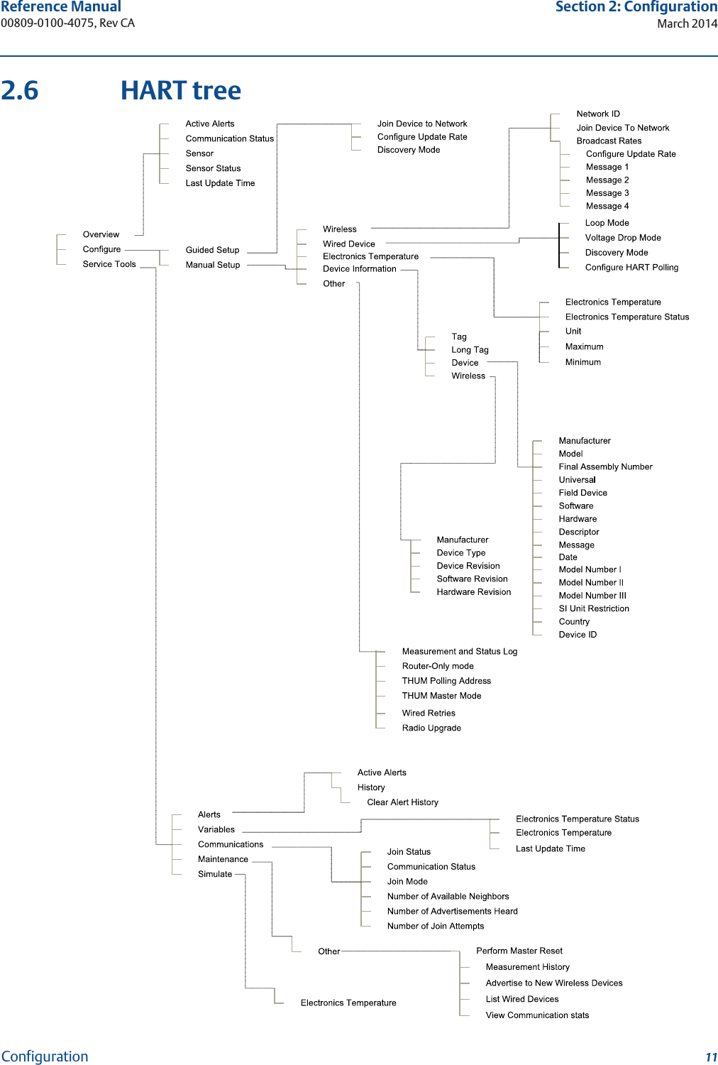
Rosemount 775-WM Wireless Industial Control Field Adapter User Manual 00809 0100 4075 Rev CA
Rosemount Inc Wireless Industial Control Field Adapter 00809 0100 4075 Rev CA
UserManual.wiki
>
Rosemount
>
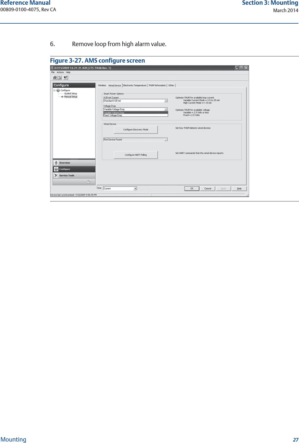
775 WM User Manual
User Manual
Navigation menu
Upload a User Manual
Namespaces
Wiki Guide
HTML
PDF
Info
Views
User Manual
Discussion / Help
Navigation