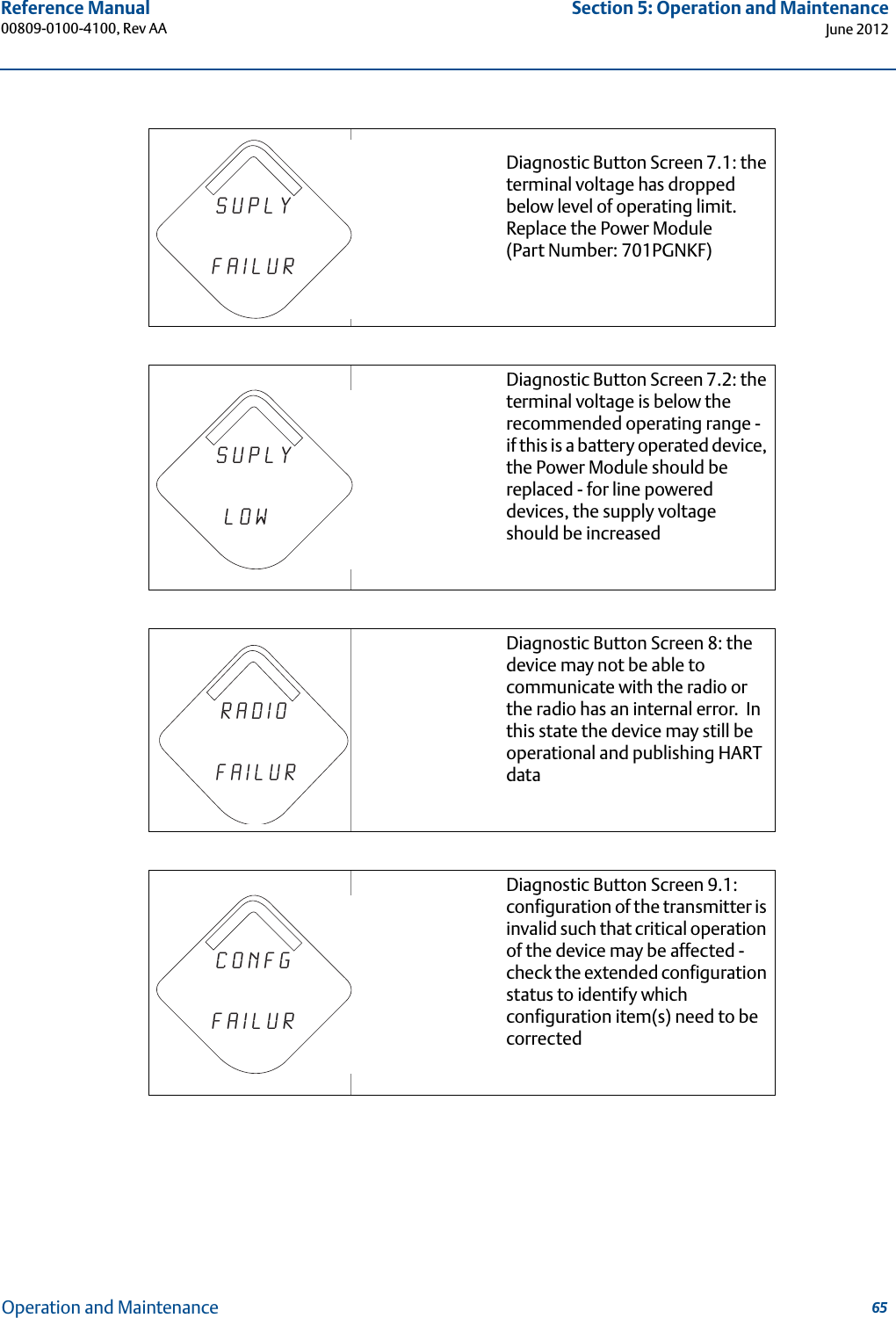
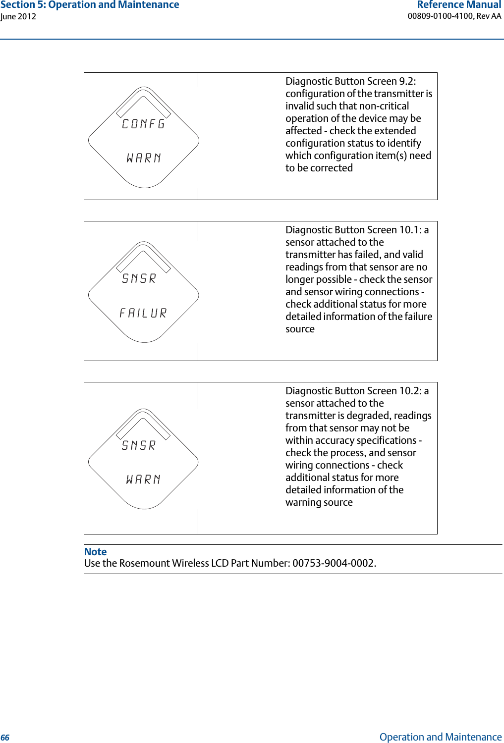
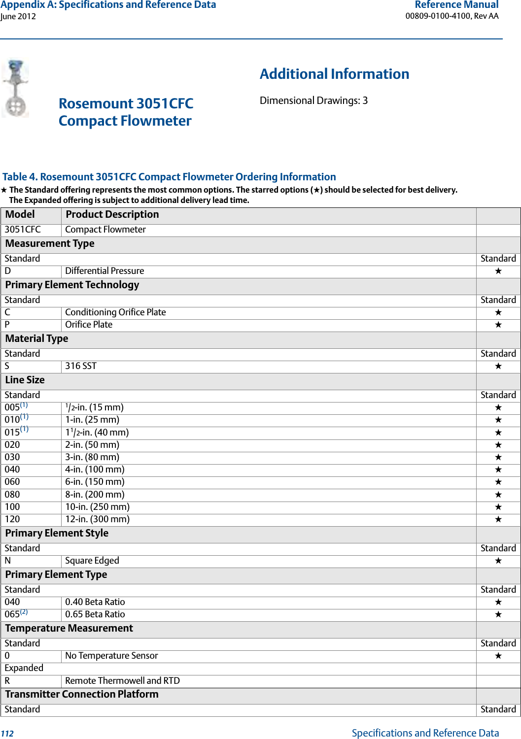
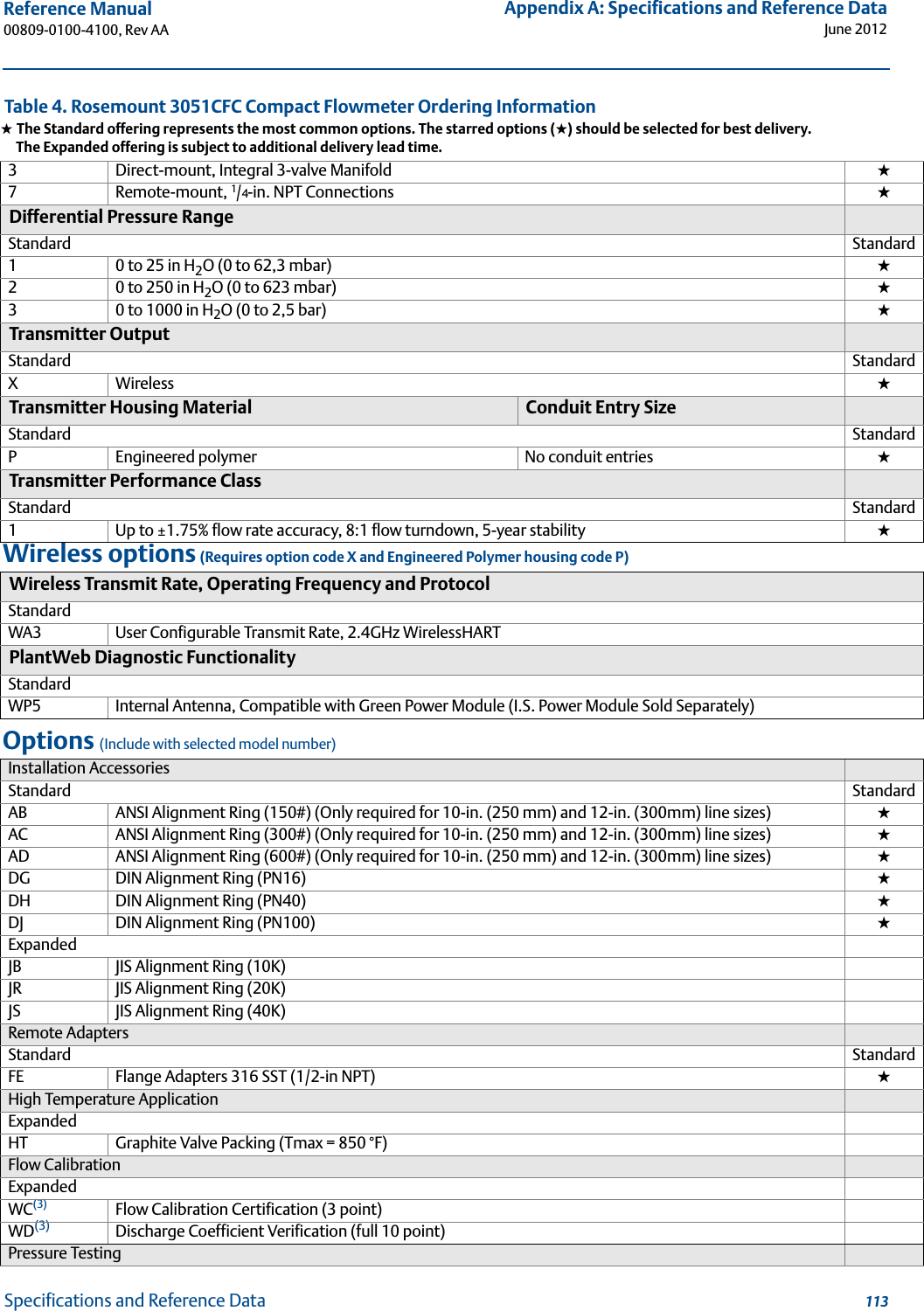
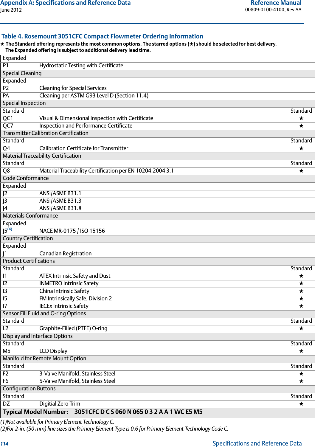
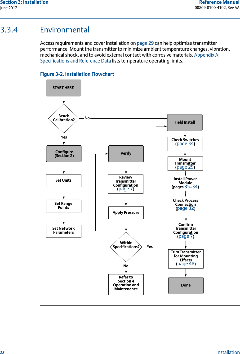
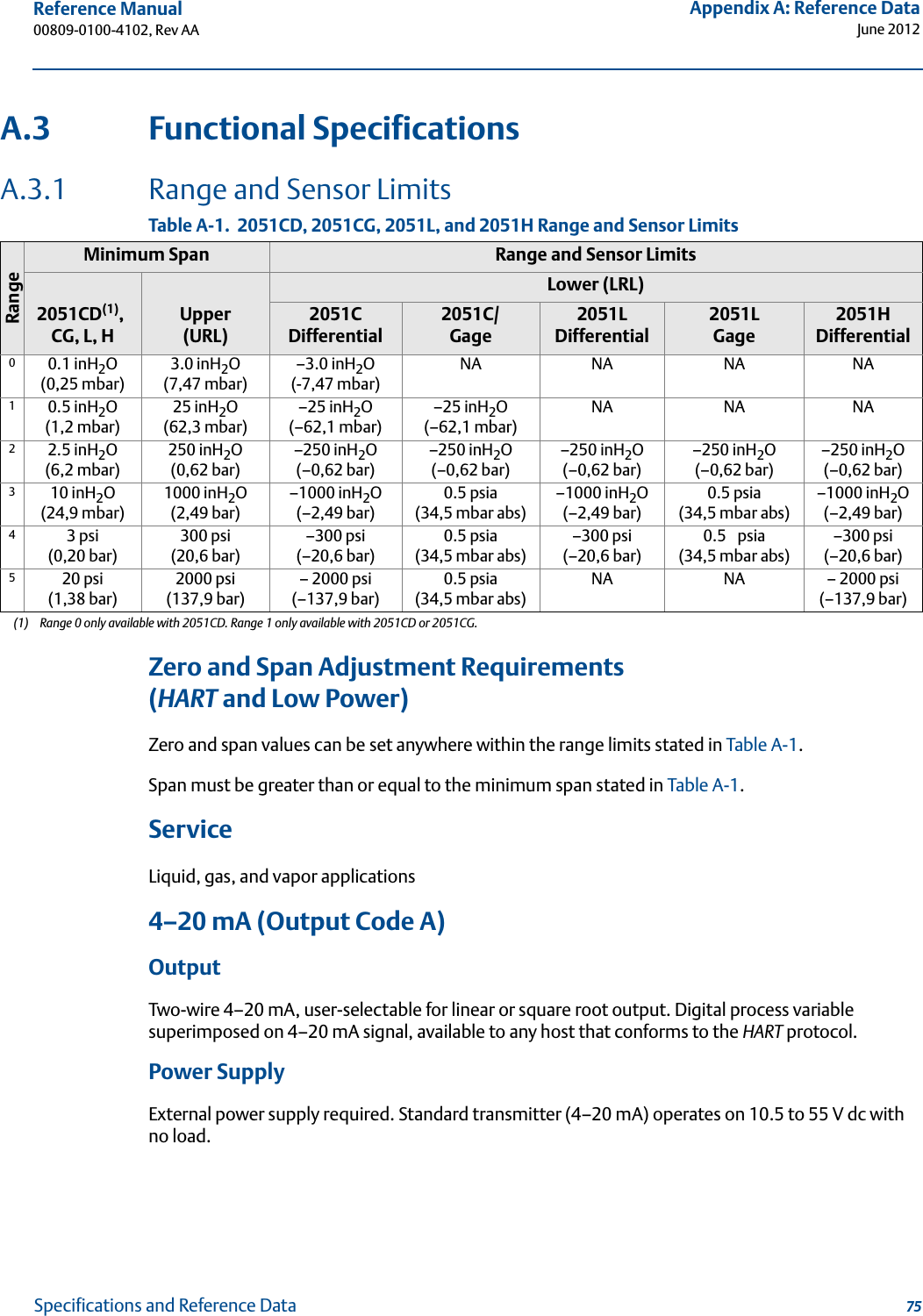
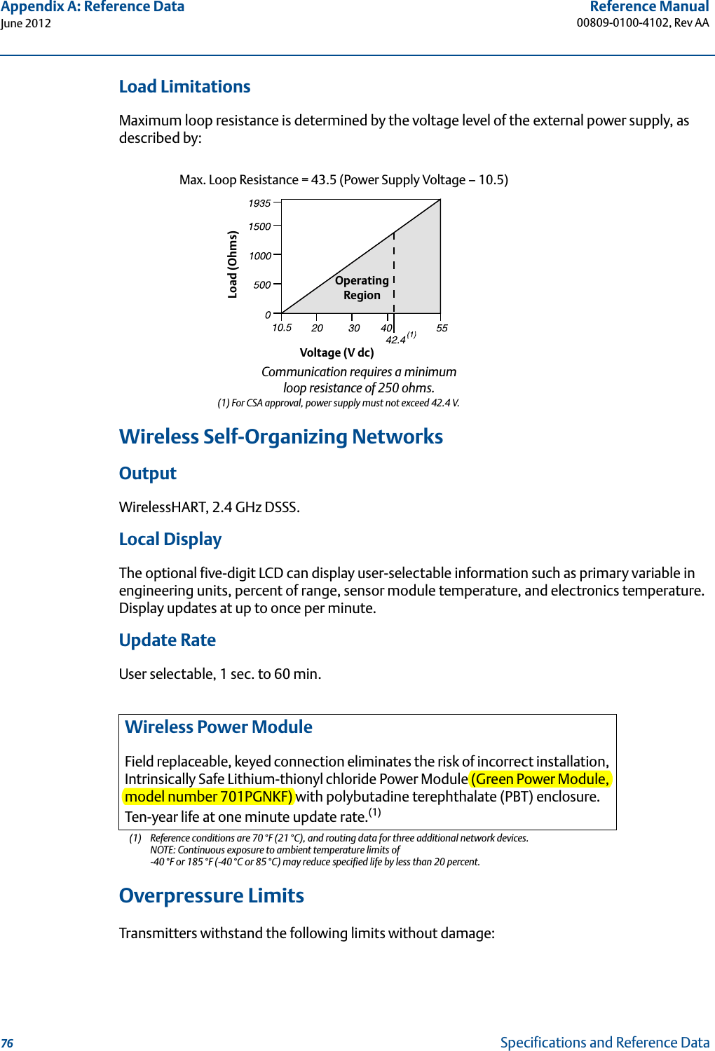
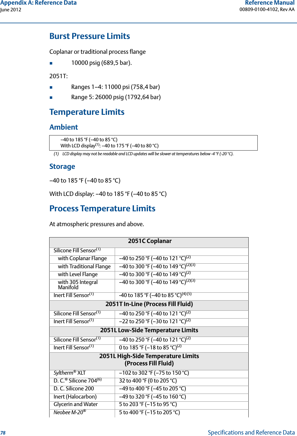
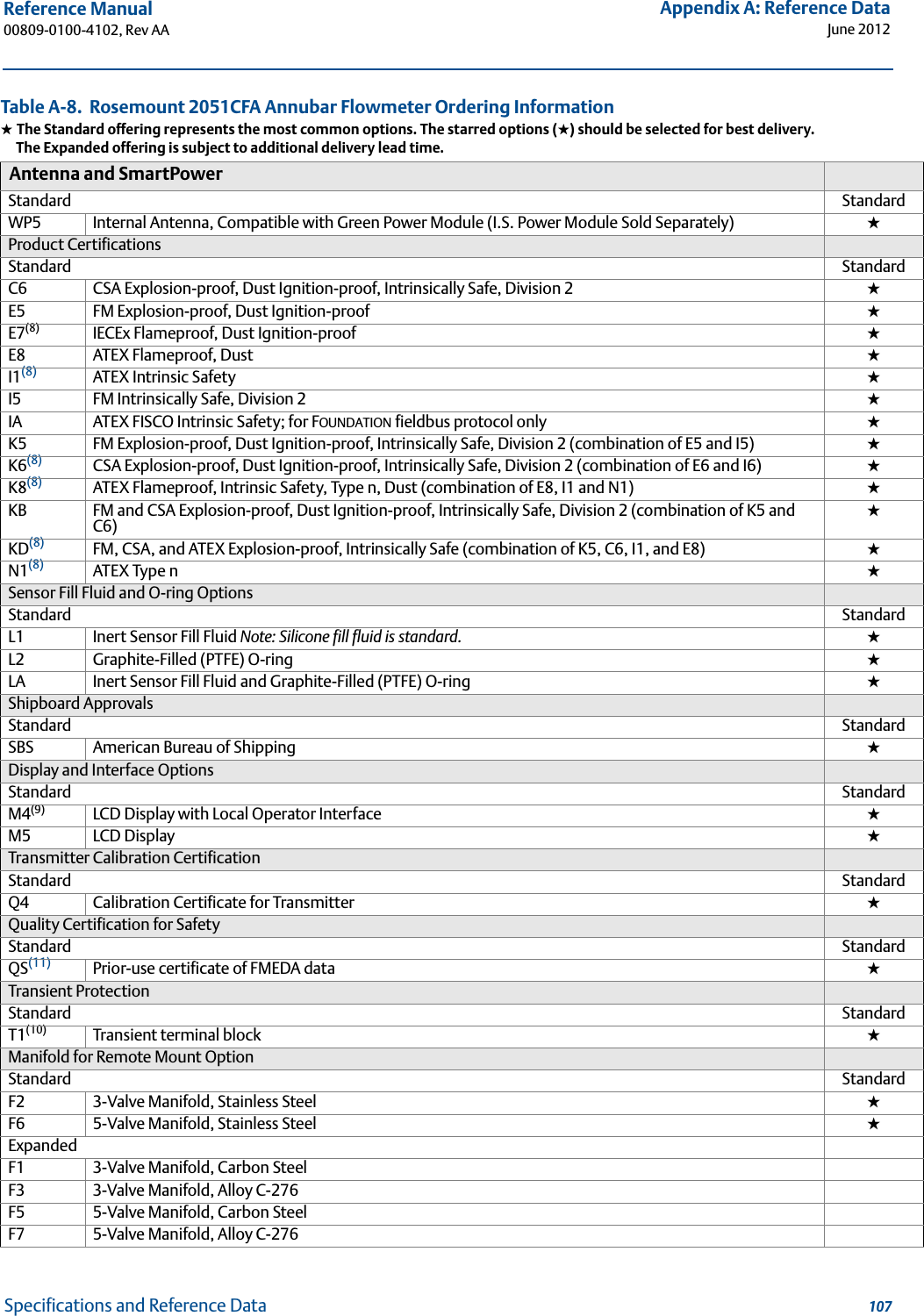
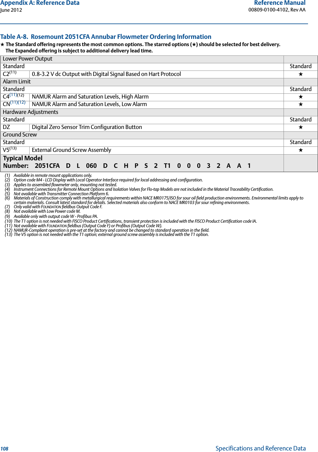
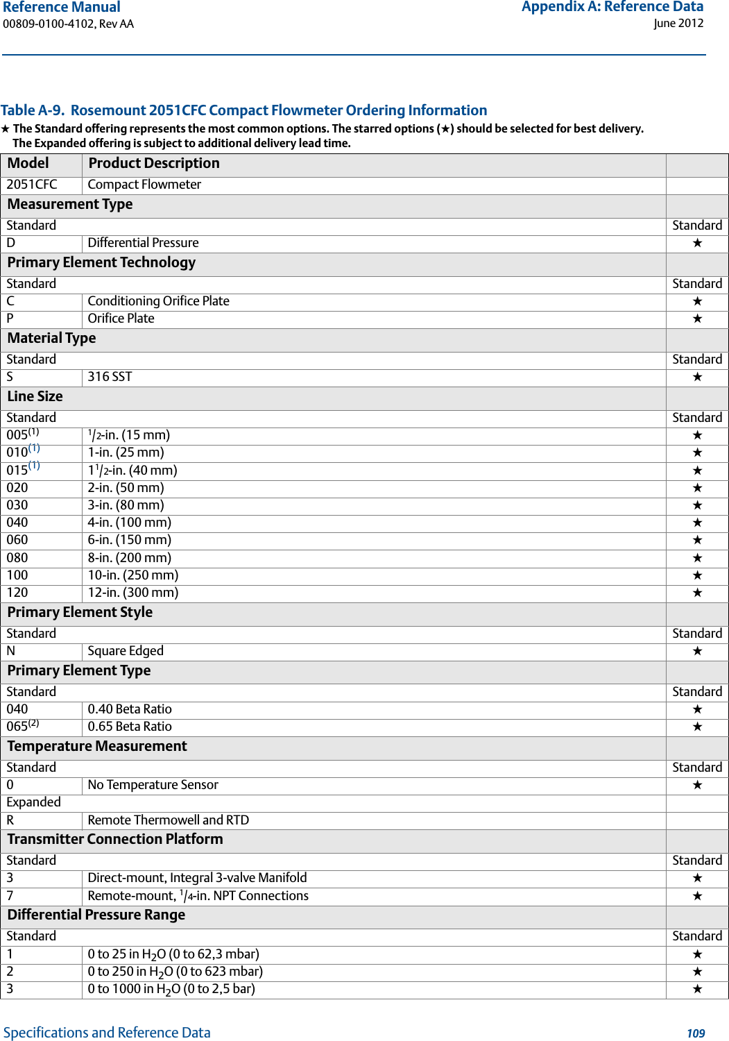
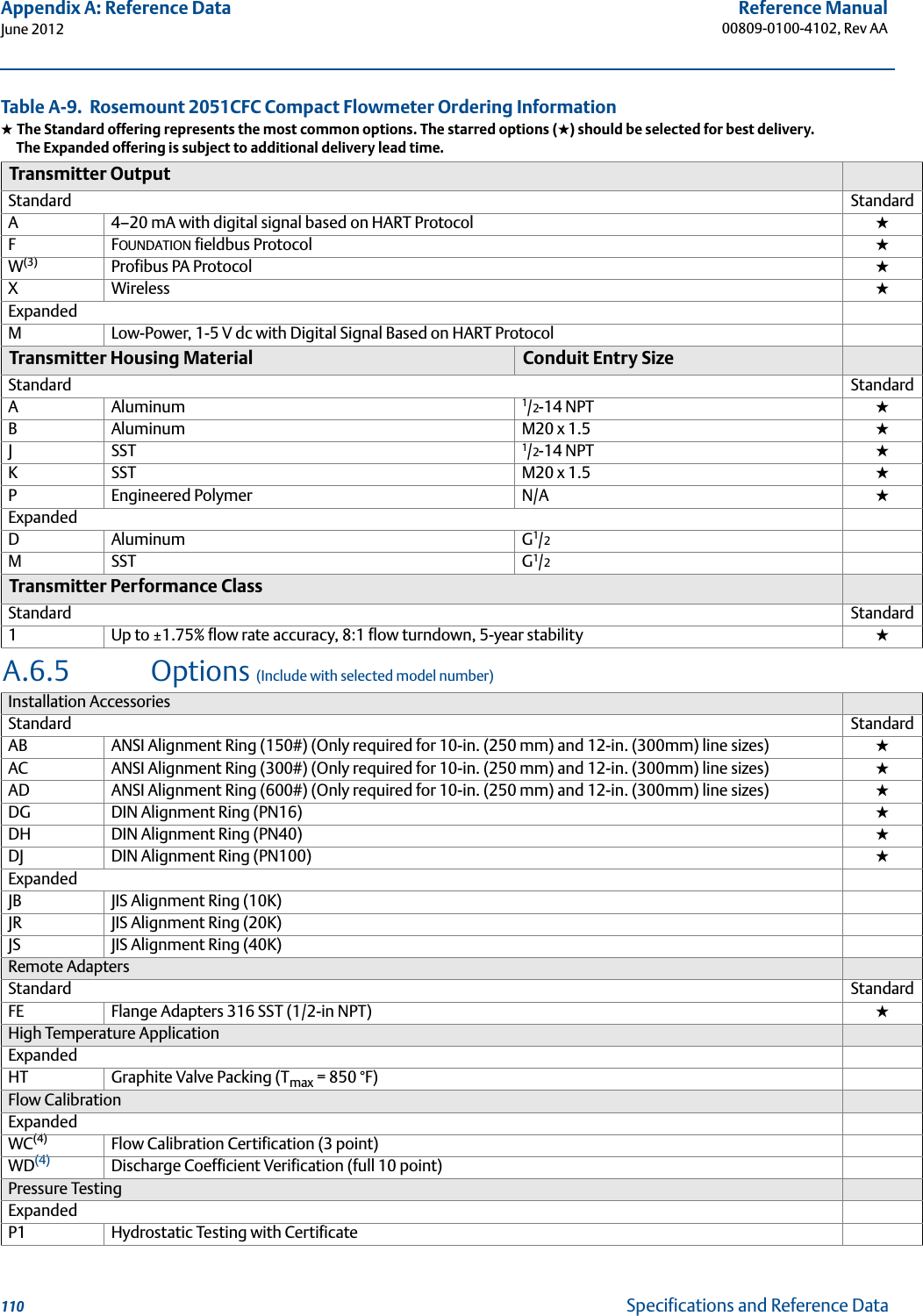
Rosemount RMCT Wireless Pressure Transmitter User Manual 2051 Wireless revAA
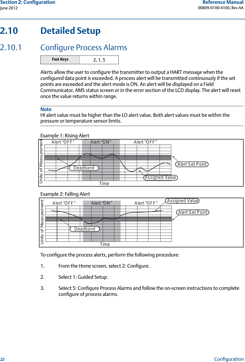
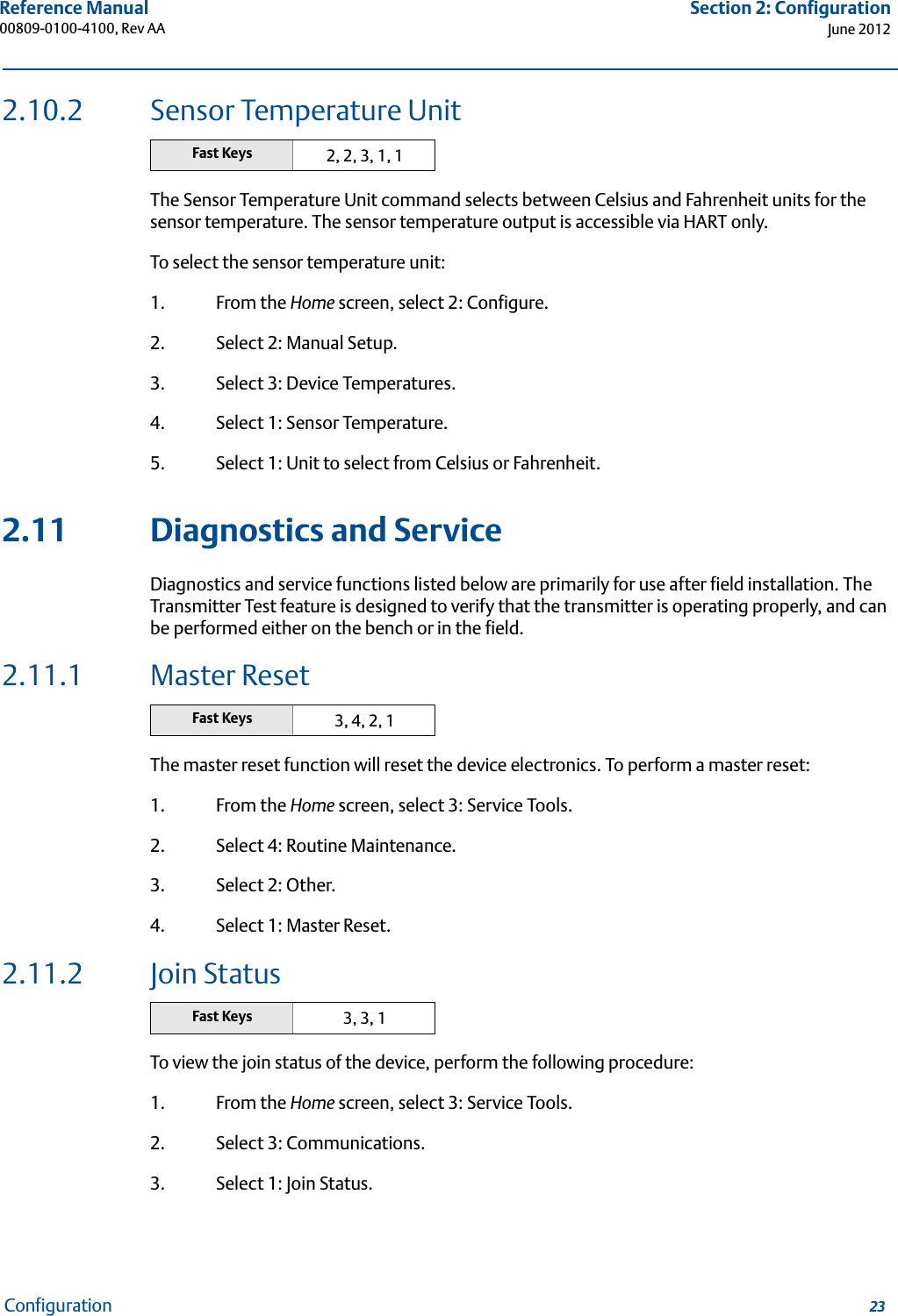
Rosemount Inc Wireless Pressure Transmitter 2051 Wireless revAA
UserManual.wiki
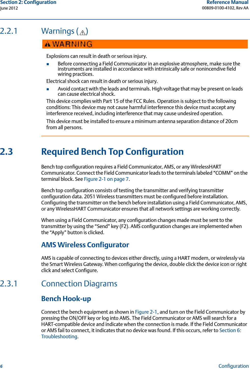
>
Rosemount
>
RMCT User Manual
User Manual
Navigation menu
Upload a User Manual
Namespaces
Wiki Guide
HTML
PDF
Info
Views
User Manual
Discussion / Help
Navigation


![31Reference Manual 00809-0100-4102, Rev AASection 3: InstallationJune 2012InstallationImpulse PipingThe piping between the process and the transmitter must accurately transfer the pressure to obtain accurate measurements. There are five possible sources of error: leaks, friction loss (particularly if purging is used), trapped gas in a liquid line, liquid in a gas line, and density variations between the legs.The best location for the transmitter in relation to the process pipe depends on the process itself. Use the following guidelines to determine transmitter location and placement of impulse piping:Keep impulse piping as short as possible.For liquid service, slope the impulse piping at least 1 inch per foot (8 cm per m) upward from the transmitter toward the process connection.For gas service, slope the impulse piping at least 1 inch per foot (8 cm per m) downward from the transmitter toward the process connection.Avoid high points in liquid lines and low points in gas lines.Make sure both impulse legs are the same temperature.Use impulse piping large enough to avoid friction effects and blockage.Vent all gas from liquid piping legs.When using a sealing fluid, fill both piping legs to the same level.When purging, make the purge connection close to the process taps and purge through equal lengths of the same size pipe. Avoid purging through the transmitter.Keep corrosive or hot (above 250 °F [121 °C]) process material out of direct contact with the SuperModule and flanges.Prevent sediment deposits in the impulse piping.Keep the liquid head balanced on both legs of the impulse piping.Avoid conditions that might allow process fluid to freeze within the process flange.](https://usermanual.wiki/Rosemount/RMCT/User-Guide-1808773-Page-39.png)


![33Reference Manual 00809-0100-4100, Rev AASection 3: InstallationJune 2012InstallationImpulse PipingThe piping between the process and the transmitter must accurately transfer the pressure to obtain accurate measurements. There are five possible sources of error: leaks, friction loss (particularly if purging is used), trapped gas in a liquid line, liquid in a gas line, and density variations between the legs.The best location for the transmitter in relation to the process pipe depends on the process itself. Use the following guidelines to determine transmitter location and placement of impulse piping:Keep impulse piping as short as possible.For liquid service, slope the impulse piping at least 1 inch per foot (8 cm per m) upward from the transmitter toward the process connection.For gas service, slope the impulse piping at least 1 inch per foot (8 cm per m) downward from the transmitter toward the process connection.Avoid high points in liquid lines and low points in gas lines.Make sure both impulse legs are the same temperature.Use impulse piping large enough to avoid friction effects and blockage.Vent all gas from liquid piping legs.When using a sealing fluid, fill both piping legs to the same level.When purging, make the purge connection close to the process taps and purge through equal lengths of the same size pipe. Avoid purging through the transmitter.Keep corrosive or hot (above 250 °F [121 °C]) process material out of direct contact with the SuperModule and flanges.Prevent sediment deposits in the impulse piping.Keep the liquid head balanced on both legs of the impulse piping.Avoid conditions that might allow process fluid to freeze within the process flange.](https://usermanual.wiki/Rosemount/RMCT/User-Guide-1808773-Page-156.png)


![54Reference Manual00809-0100-4100, Rev AASection 5: Operation and MaintenanceJune 2012Operation and MaintenanceNoteSelect pressure input values so that lower and upper values are equal to or outside the Lower and Upper Operating points. Do not attempt to obtain reverse output by reversing the high and low points. The transmitter allows approximately five percent deviation. 5.2.4 Recall Factory Trim—Sensor TrimThe Recall Factory Trim—Sensor Trim command allows the restoration of the as-shipped factory settings of the sensor trim. This command can be useful for recovering from an inadvertent zero trim of an absolute pressure unit or inaccurate pressure source.To restore sensor trim to as-shipped factory settings:1. From the Home screen, Select 3: Service Tools.2. Select 4: Routine Maintenance.3. Select 1: Sensor Calibration.4. Select 6: Recall Factory Trim.5.2.5 Line Pressure Effect (Range 2 and Range 3)The following specifications show the static pressure effect for the Rosemount 3051 Range 2 and Range 3 pressure transmitters used in differential pressure applications where line pressure exceeds 2000 psi (138 bar). Zero Effect± 0.1% of the upper range limit plus an additional ± 0.1% of upper range limit error for each 1000 psi (69 bar) of line pressure above 2000 psi (138 bar).Example: Line pressure is 3000 psi (207 bar) for Ultra performance transmitter. Zero effect error calculation:± {0.05 + 0.1 x [3 kpsi - 2 kpsi]} = ± 0.15% of the upper range limitSpan EffectRefer to “Line Pressure Effect” on page 82. 5.2.6 Compensating for Line Pressure (Range 4 and Range 5)The Rosemount 3051 Wireless Range 4 and 5 pressure transmitters require a special calibration procedure when used in differential pressure applications. The purpose of this procedure is to optimize transmitter performance by reducing the effect of static line pressure in these applications. The 3051 Wireless differential pressure transmitters (Ranges 1, 2, and 3) do not require this procedure because optimization occurs in the sensor.Fast Keys 3, 4, 1, 6](https://usermanual.wiki/Rosemount/RMCT/User-Guide-1808773-Page-177.png)
![55Reference Manual 00809-0100-4100, Rev AASection 5: Operation and MaintenanceJune 2012Operation and MaintenanceApplying high static pressure to the 3051 Wireless Range 4 and Range 5 pressure transmitters causes a systematic shift in the output. This shift is linear with static pressure; correct it by performing the “Sensor Trim” procedure on page 53.The following specifications show the static pressure effect for the 3051 Wireless Range 4 and Range 5 transmitters used in differential pressure applications:Zero Effect:± 0.1% of the upper range limit per 1000 psi (69 bar) for line pressures from 0 to 2000 psi (0 to 138 bar)For line pressures above 2000 psi (138 bar), the zero effect error is ± 0.2% of the upper range limit plus an additional ± 0.2% of upper range limit error for each 1000 psi (69 bar) of line pressure above 2000 psi (138 bar).Example: Line pressure is 3000 psi (3 kpsi). Zero effect error calculation:± {0.2 + 0.2 x [3 kpsi - 2 kpsi]} = ± 0.4% of the upper range limitSpan Effect:Correctable to ±0.2% of reading per 1000 psi (69 bar) for line pressures from 0 to 3626 psi (0 to 250 bar)The systematic span shift caused by the application of static line pressure is -1.00% of reading per 1000 psi (69 bar) for Range 4 transmitters, and -1.25% of reading per 1000 psi (69 bar) for Range 5 transmitters.Use the following example to compute corrected input values.ExampleA transmitter with model number 3051_CD4 will be used in a differential pressure application where the static line pressure is 1200 psi (83 bar). The transmitter output is ranged with 4 mA at 500 inH2O (1,2 bar) and 20 mA at 1500 inH2O (3,7 bar).To correct for systematic error caused by high static line pressure, first use the following formulas to determine corrected values for the low trim and high trim.](https://usermanual.wiki/Rosemount/RMCT/User-Guide-1808773-Page-178.png)